WO2012093734A1 - Illumination device - Google Patents
Illumination device Download PDFInfo
- Publication number
- WO2012093734A1 WO2012093734A1 PCT/JP2012/050230 JP2012050230W WO2012093734A1 WO 2012093734 A1 WO2012093734 A1 WO 2012093734A1 JP 2012050230 W JP2012050230 W JP 2012050230W WO 2012093734 A1 WO2012093734 A1 WO 2012093734A1
- Authority
- WO
- WIPO (PCT)
- Prior art keywords
- light
- pair
- reflecting
- reflecting surface
- fluorescent tube
- Prior art date
Links
Images


Classifications
-
- F—MECHANICAL ENGINEERING; LIGHTING; HEATING; WEAPONS; BLASTING
- F21—LIGHTING
- F21V—FUNCTIONAL FEATURES OR DETAILS OF LIGHTING DEVICES OR SYSTEMS THEREOF; STRUCTURAL COMBINATIONS OF LIGHTING DEVICES WITH OTHER ARTICLES, NOT OTHERWISE PROVIDED FOR
- F21V7/00—Reflectors for light sources
- F21V7/0008—Reflectors for light sources providing for indirect lighting
-
- F—MECHANICAL ENGINEERING; LIGHTING; HEATING; WEAPONS; BLASTING
- F21—LIGHTING
- F21K—NON-ELECTRIC LIGHT SOURCES USING LUMINESCENCE; LIGHT SOURCES USING ELECTROCHEMILUMINESCENCE; LIGHT SOURCES USING CHARGES OF COMBUSTIBLE MATERIAL; LIGHT SOURCES USING SEMICONDUCTOR DEVICES AS LIGHT-GENERATING ELEMENTS; LIGHT SOURCES NOT OTHERWISE PROVIDED FOR
- F21K9/00—Light sources using semiconductor devices as light-generating elements, e.g. using light-emitting diodes [LED] or lasers
- F21K9/20—Light sources comprising attachment means
- F21K9/27—Retrofit light sources for lighting devices with two fittings for each light source, e.g. for substitution of fluorescent tubes
-
- F—MECHANICAL ENGINEERING; LIGHTING; HEATING; WEAPONS; BLASTING
- F21—LIGHTING
- F21K—NON-ELECTRIC LIGHT SOURCES USING LUMINESCENCE; LIGHT SOURCES USING ELECTROCHEMILUMINESCENCE; LIGHT SOURCES USING CHARGES OF COMBUSTIBLE MATERIAL; LIGHT SOURCES USING SEMICONDUCTOR DEVICES AS LIGHT-GENERATING ELEMENTS; LIGHT SOURCES NOT OTHERWISE PROVIDED FOR
- F21K9/00—Light sources using semiconductor devices as light-generating elements, e.g. using light-emitting diodes [LED] or lasers
- F21K9/60—Optical arrangements integrated in the light source, e.g. for improving the colour rendering index or the light extraction
-
- F—MECHANICAL ENGINEERING; LIGHTING; HEATING; WEAPONS; BLASTING
- F21—LIGHTING
- F21S—NON-PORTABLE LIGHTING DEVICES; SYSTEMS THEREOF; VEHICLE LIGHTING DEVICES SPECIALLY ADAPTED FOR VEHICLE EXTERIORS
- F21S2/00—Systems of lighting devices, not provided for in main groups F21S4/00 - F21S10/00 or F21S19/00, e.g. of modular construction
-
- F—MECHANICAL ENGINEERING; LIGHTING; HEATING; WEAPONS; BLASTING
- F21—LIGHTING
- F21S—NON-PORTABLE LIGHTING DEVICES; SYSTEMS THEREOF; VEHICLE LIGHTING DEVICES SPECIALLY ADAPTED FOR VEHICLE EXTERIORS
- F21S8/00—Lighting devices intended for fixed installation
- F21S8/02—Lighting devices intended for fixed installation of recess-mounted type, e.g. downlighters
- F21S8/026—Lighting devices intended for fixed installation of recess-mounted type, e.g. downlighters intended to be recessed in a ceiling or like overhead structure, e.g. suspended ceiling
-
- F—MECHANICAL ENGINEERING; LIGHTING; HEATING; WEAPONS; BLASTING
- F21—LIGHTING
- F21V—FUNCTIONAL FEATURES OR DETAILS OF LIGHTING DEVICES OR SYSTEMS THEREOF; STRUCTURAL COMBINATIONS OF LIGHTING DEVICES WITH OTHER ARTICLES, NOT OTHERWISE PROVIDED FOR
- F21V7/00—Reflectors for light sources
- F21V7/0025—Combination of two or more reflectors for a single light source
- F21V7/0033—Combination of two or more reflectors for a single light source with successive reflections from one reflector to the next or following
-
- F—MECHANICAL ENGINEERING; LIGHTING; HEATING; WEAPONS; BLASTING
- F21—LIGHTING
- F21V—FUNCTIONAL FEATURES OR DETAILS OF LIGHTING DEVICES OR SYSTEMS THEREOF; STRUCTURAL COMBINATIONS OF LIGHTING DEVICES WITH OTHER ARTICLES, NOT OTHERWISE PROVIDED FOR
- F21V7/00—Reflectors for light sources
- F21V7/005—Reflectors for light sources with an elongated shape to cooperate with linear light sources
-
- F—MECHANICAL ENGINEERING; LIGHTING; HEATING; WEAPONS; BLASTING
- F21—LIGHTING
- F21V—FUNCTIONAL FEATURES OR DETAILS OF LIGHTING DEVICES OR SYSTEMS THEREOF; STRUCTURAL COMBINATIONS OF LIGHTING DEVICES WITH OTHER ARTICLES, NOT OTHERWISE PROVIDED FOR
- F21V7/00—Reflectors for light sources
- F21V7/04—Optical design
- F21V7/048—Optical design with facets structure
-
- F—MECHANICAL ENGINEERING; LIGHTING; HEATING; WEAPONS; BLASTING
- F21—LIGHTING
- F21Y—INDEXING SCHEME ASSOCIATED WITH SUBCLASSES F21K, F21L, F21S and F21V, RELATING TO THE FORM OR THE KIND OF THE LIGHT SOURCES OR OF THE COLOUR OF THE LIGHT EMITTED
- F21Y2103/00—Elongate light sources, e.g. fluorescent tubes
- F21Y2103/10—Elongate light sources, e.g. fluorescent tubes comprising a linear array of point-like light-generating elements
-
- F—MECHANICAL ENGINEERING; LIGHTING; HEATING; WEAPONS; BLASTING
- F21—LIGHTING
- F21Y—INDEXING SCHEME ASSOCIATED WITH SUBCLASSES F21K, F21L, F21S and F21V, RELATING TO THE FORM OR THE KIND OF THE LIGHT SOURCES OR OF THE COLOUR OF THE LIGHT EMITTED
- F21Y2103/00—Elongate light sources, e.g. fluorescent tubes
- F21Y2103/30—Elongate light sources, e.g. fluorescent tubes curved
- F21Y2103/33—Elongate light sources, e.g. fluorescent tubes curved annular
-
- F—MECHANICAL ENGINEERING; LIGHTING; HEATING; WEAPONS; BLASTING
- F21—LIGHTING
- F21Y—INDEXING SCHEME ASSOCIATED WITH SUBCLASSES F21K, F21L, F21S and F21V, RELATING TO THE FORM OR THE KIND OF THE LIGHT SOURCES OR OF THE COLOUR OF THE LIGHT EMITTED
- F21Y2115/00—Light-generating elements of semiconductor light sources
- F21Y2115/10—Light-emitting diodes [LED]
Definitions
- the present invention relates to an illumination device using an LED element.
- a conventional indoor lighting device includes a fluorescent tube and an umbrella or a reflector disposed on the back side of the fluorescent tube. Light emitted from the front of the fluorescent tube is directly irradiated into the room, and the fluorescent tube It is known that light radiated from the back side is reflected by an umbrella or a reflector and is radiated supplementarily into the room (for example, see Utility Model Registration No. 312998 and JP-A-2008-300230). ).
- the fluorescent lamp includes a plurality of cold cathode tubes extending in a predetermined direction, a flat reflector extending along the cold cathode tubes, and a light transmitting member extending along the cold cathode tubes.
- a cold cathode tube is disposed between the reflector and the translucent cover.
- each LED element is arranged so that the optical axis faces directly above, and a first reflecting surface is arranged above the LED element, and the first reflecting surface
- the ridge line is convex downward.
- a first reflection surface is disposed in a space between the pair of second reflection surfaces, and light reflected by the first reflection surface is further reflected by the second reflection surface, and light from each LED element.
- the light which is not irradiated to the 1st reflective surface is reflected by the 2nd reflective surface, and the light reflected by the 2nd reflective surface is irradiated toward irradiation positions, such as an indoor floor.
- the strong light around the optical axis among the light emitted from each LED element is reflected by the first reflecting surface, and most of the reflected light is first reflected with respect to the optical axis of each LED element.
- the light travels outward so as to form an angle corresponding to the inclination angle of the surface, and the light is irradiated to the irradiation position such as the floor by the second reflecting surface.
- the specification of the second reflecting surface as appropriate, it is possible to reduce the unevenness of illuminance at the irradiation position as compared with the case where the light of each LED element is directly applied to the irradiation position such as the floor. it can.
- each LED element is arranged so that the optical axis faces directly above the indoor ceiling, strong light around the optical axis is reflected by the first reflecting surface among the light emitted from each LED element, and the reflection thereof.
- the irradiated light is irradiated to the irradiation position such as the floor by the second reflection surface, and the light directly irradiated to the second reflection surface from each LED element is also reflected toward the irradiation position such as the floor.
- the light from each LED element can be efficiently irradiated to irradiation positions, such as a floor. That is, it is extremely advantageous for energy saving while ensuring the illuminance at the irradiation position.
- the strong light near the center of the light irradiation range among the light emitted from the light source is reflected by the first reflecting surface, and most of the reflected light is first reflected with respect to the optical axis of each LED element.
- the light travels outward so as to form an angle corresponding to the inclination angle of the surface, and the light is irradiated to the irradiation position such as the floor by the second reflecting surface.
- the specification of the second reflecting surface as appropriate, it is possible to reduce the unevenness of illuminance at the irradiation position as compared with the case where the light of each LED element is directly applied to the irradiation position such as the floor. it can.
- the lighting device of the present invention is composed of a plurality of LED elements arranged in parallel in a predetermined direction and a translucent material, extends in the direction in which the LED elements are arranged, and covers the plurality of LED elements.
- a light source that emits light in a predetermined light irradiation angle range in a direction orthogonal to the direction in which the LED elements are arranged, and extends in the direction in which the LED elements of the light source are arranged
- a ridge line that is convex toward the light source side is formed at a portion where the pair of surfaces intersect, and the ridge line is disposed substantially at the center of the light irradiation angle range of the light source.
- a pair of second reflecting surfaces provided on both outer sides of the first reflecting surface in a direction intersecting with the parallel arrangement direction of the LED elements, and the ridgeline of the first reflecting surface and the light source of the light source.
- the distance from the translucent cover is less than or equal to one time the predetermined width dimension of the first reflecting surface, and the pair of second reflecting surfaces is arranged with the first reflecting surface in the space between them, The light reflected by the first reflecting surface and the light directly irradiated from the light source are reflected.
- a convex ridge line is formed toward the LED element side of the light source at a portion where the pair of surfaces of the first reflecting surface intersect, and the ridge line is disposed at the approximate center of the light irradiation range of the light source, Since the pair of surfaces of the first reflecting surface form an angle of 60 ° to 120 ° in the vicinity of the ridgeline, the light from each LED element of the light source is reflected by the first reflecting surface, and the reflected light Most of the light travels outward so as to form an angle corresponding to the tilt angle of the first reflecting surface (for example, an angle of 45 ° or more) with respect to the optical axis of the light source.
- the first reflective surface has a pair of second reflective surfaces provided on both outer sides of the first reflective surface, and the first reflective surface is disposed in a space between the pair of second reflective surfaces.
- the light reflected by the reflecting surface is further reflected by the second reflecting surface, and the light that is not irradiated on the first reflecting surface among the light from each LED element of the light source is reflected by the second reflecting surface. ing.
- each LED element is arranged so that the optical axis is directly above the indoor ceiling, strong light in the vicinity of the center of the light irradiation range is reflected by the first reflecting surface among the light emitted from the light source, and the reflection thereof.
- the irradiated light is irradiated to a predetermined irradiation position such as a floor by the second reflecting surface, and the light directly irradiated to the second reflecting surface from the light source is also reflected toward the predetermined irradiation position such as the floor.
- the light from each LED element of a light source can be efficiently irradiated to predetermined irradiation positions, such as a floor. That is, it is extremely advantageous for energy saving while ensuring the illuminance at the irradiation position.
- the lighting device of the present invention comprises a fluorescent tube extending in a predetermined direction, an in-lamp reflector extending along the fluorescent tube, and a translucent material in the extending direction of the fluorescent tube.
- a predetermined light irradiation angle range in a direction perpendicular to the extending direction of the fluorescent tube, the fluorescent tube being disposed between the reflecting plate and the transparent cover.
- a pair of surfaces extending in the extending direction of the fluorescent tube of the fluorescent lamp, and a ridge line convex toward the fluorescent lamp side is formed at the intersection of the pair of surfaces.
- the first reflecting surface is disposed on the first reflecting surface to reflect light reflected by the first reflecting surface and light directly emitted from the fluorescent lamp.
- a convex ridge line is formed toward the fluorescent lamp side at a portion where the pair of surfaces of the first reflecting surface intersect, and the ridge line is within 10 ° with respect to the center of the light irradiation angle range of the fluorescent lamp. Since the pair of surfaces of the first reflecting surface form an angle of 60 ° to 120 ° in the vicinity of the ridgeline, the light from the fluorescent lamp is arranged to receive the light in the range of Most of the reflected light travels outward so as to form an angle corresponding to the inclination angle of the first reflecting surface (for example, an angle of 45 ° or more) with respect to the optical axis surface of the fluorescent lamp. It will be.
- the first reflective surface has a pair of second reflective surfaces provided on both outer sides of the first reflective surface, and the first reflective surface is disposed in a space between the pair of second reflective surfaces.
- the light reflected by the reflecting surface is further reflected by the second reflecting surface, and the light directly irradiated from the fluorescent lamp is also reflected by the second reflecting surface.
- a fluorescent lamp is disposed so that the optical axis surface faces upward, a first reflecting surface is disposed above the fluorescent lamp, and a ridgeline of the first reflecting surface Becomes convex downward.
- the first reflecting surface is disposed in the space between the pair of second reflecting surfaces, and the light reflected by the first reflecting surface is further reflected by the second reflecting surface and directly irradiated from the fluorescent lamp.
- the reflected light is also reflected by the second reflecting surface, and the light reflected by the second reflecting surface is irradiated toward a predetermined irradiation position such as an indoor floor.
- Convex ridges are formed toward the fluorescent tube at the intersection of the pair of surfaces extending in the direction, and the predetermined light irradiation angle of the light irradiated from the fluorescent tube
- a first reflecting surface disposed so as to receive light in a range within 10 ° with respect to the center of the range, and the pair of surfaces having an angle of 60 ° to 120 ° with each other in the vicinity of the ridgeline;
- the first reflecting surface in a direction orthogonal to the extending direction of the fluorescent tube
- a pair of second reflecting surfaces provided on both outer sides, and the pair of second reflecting surfaces are arranged such that the first reflecting surface is disposed in a space between them, and is reflected from the first reflecting surface. The reflected light and the light directly irradiated from the fluorescent tube are reflected.
- a convex ridge line is formed toward the fluorescent tube side at a portion where the pair of surfaces of the first reflecting surface intersect, and the ridge line is within 10 ° with respect to the center of the predetermined light irradiation angle range.
- the pair of surfaces of the first reflecting surface form an angle of 60 ° to 120 ° in the vicinity of the ridge line, so that the light from the fluorescent tube is the first reflecting surface.
- Most of the reflected light travels outward so as to form an angle corresponding to the inclination angle of the first reflecting surface (for example, an angle of 45 ° or more) with respect to the central surface. .
- the first reflective surface has a pair of second reflective surfaces provided on both outer sides of the first reflective surface, and the first reflective surface is disposed in a space between the pair of second reflective surfaces.
- the light reflected by the reflecting surface is further reflected by the second reflecting surface, and the light directly irradiated from the fluorescent lamp is also reflected by the second reflecting surface.
- the first reflecting surface is disposed above the fluorescent tube, and the ridge line of the first reflecting surface is convex downward.
- the first reflecting surface is disposed in the space between the pair of second reflecting surfaces, and the light reflected by the first reflecting surface is further reflected by the second reflecting surface and directly irradiated from the fluorescent tube.
- the reflected light is also reflected by the second reflecting surface, and the light reflected by the second reflecting surface is irradiated toward a predetermined irradiation position such as an indoor floor through the light transmitting cover.
- an illuminating device that can save energy and has less uneven illuminance at the irradiation position. Moreover, energy saving can be achieved while ensuring the illuminance at the irradiation position.
- Sectional drawing of the principal part of the illuminating device of 15th Embodiment of this invention Sectional drawing of the principal part of the illuminating device of 16th Embodiment of this invention.
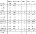
- Table showing experimental results Sectional drawing of the principal part of the illuminating device of 18th Embodiment of this invention.
- the chip-type LED element 10 is used, but a bullet-type or other types of LED elements can also be used.
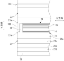
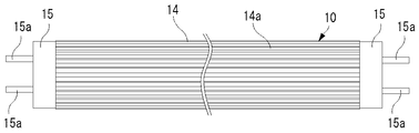
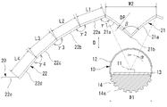
- the heat sink 14 is made of a metal material such as aluminum, for example, and has a plurality of heat radiation fins 14 a extending in the longitudinal direction of the light source 10 at positions that constitute the outer peripheral surface of the light source 10.
- the light source 10 is attached to the indoor ceiling by inserting the terminal 15a of each base 15 into a socket 100 provided on the indoor ceiling. Further, when the light source 10 is attached to the ceiling in the room, each LED element 11 of the light source 10 is attached so as to face directly above.
- each LED element 11 of the light source 10 faces directly above, and the heat sink 14 of the light source 10 is positioned below the light source 10.
- the socket 100 an existing socket for attaching a fluorescent lamp can be used as it is, and the base 15 or the substrate 13 is provided with a circuit for converting an alternating current into a direct current suitable for each LED 11.
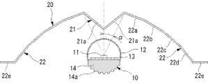
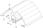
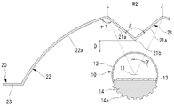
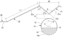
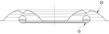
- the reflection plate 20 is formed by bending a metal plate such as aluminum and has a first reflection surface 21 and a pair of second reflection surfaces 22.
- each of the reflecting surfaces 21 and 22 is formed to have a rough surface or have irregularities so that the center line average roughness is 0.5 ⁇ m or more.
- the surface of the aluminum plate constituting each of the reflecting surfaces 21 and 22 is subjected to rough surface processing and anodic oxide coating processing such as shot blasting so that the center line average roughness is 0.5 ⁇ m or more. .
- the pair of surfaces 21a may be disposed so as to receive light in the predetermined light irradiation angle range ⁇ in the Y direction.
- the width dimension W2 of the first reflecting surface 21 in the Y direction is 36 mm.
- the plurality of LED elements 11 are arranged in a line, and the center of the light irradiation range in the Y direction of the light source 10 coincides with the optical axis of the LED element 11.
- the ridge line 21 b of the first reflecting surface 21 is arranged at the center of the light irradiation range in the Y direction of the light source 10.
- the distance D between the ridge line 21b of the first reflecting surface 21 and the light transmitting cover 12 of the light source 10 is about 1/3 of the width dimension W2 of the first reflecting surface W2.
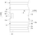
- Each second reflecting surface 22 is provided on both outer sides in the Y direction with respect to the first reflecting surface 21, and the first reflecting surface 21 is arranged in a space between the pair of second reflecting surfaces 22.
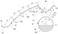
- Each of the second reflecting surfaces 22 includes a first surface 22a that constitutes a portion closest to the first reflecting surface 21, a second surface 22b that constitutes a portion next to the first reflecting surface 21, and Next, it has the 3rd surface 22c which comprises the part close
- Each of the first to fourth surfaces 22a to 22d is a flat surface and extends in the X direction.
- a flange portion 23 is provided at the outer end of the fourth surface 22d, and the flange portion 23 is provided for mounting to the indoor ceiling.
- the first surface 22a forms an angle ⁇ 1 ( ⁇ 1 is 120 ° in the present embodiment) with the surface 21a of the first reflecting surface 21, and the second surface 22b forms an angle ⁇ 2 with the first surface 22a (in the present embodiment).
- ⁇ 2 forms 170 °
- the third surface 22c forms an angle ⁇ 3 with the second surface 22b (in this embodiment, ⁇ 3 is 170 °)
- the fourth surface 22d forms an angle ⁇ 4 with the third surface 22c.
- ⁇ 4 is 170 °.
- the width dimensions L1 to L4 of the first to fourth surfaces 22a to 22d are each 19 mm.
- the first reflection surface 21 is disposed in the space between, the light reflected by the first reflection surface 21 is further reflected by the second reflection surface 22, and the light from the light source 10 is reflected on the first reflection surface. Light that is not irradiated is reflected by the second reflecting surface.
- each LED element 11 is arranged so that the optical axis faces directly above, the first reflecting surface 21 is arranged above the LED element 11, and the ridge line 21b of the first reflecting surface 21 is convex downward. It has become.
- the first reflecting surface 21 is disposed in the space between the pair of second reflecting surfaces 22, and the light reflected by the first reflecting surface 21 is further reflected by the second reflecting surface 22, and each LED Of the light from the element 11, the light not irradiated on the first reflecting surface 21 is reflected by the second reflecting surface, and the light reflected by the second reflecting surface 22 is irradiated toward the irradiation position such as the indoor floor. Is done.
- each LED element 11 of the light source 10 faces upward, and a heat sink 14 for preventing a temperature rise of each LED element 11 in the light source 10 is disposed below the LED element 11. ing. That is, in the light source 10, each LED element 11 is disposed on the first reflecting surface 21 side of the reflecting plate 20, and the heat sink 14 is disposed on the side away from the first reflecting surface 21. It becomes easy to hit air, and heat can be efficiently dissipated.
- each of the reflecting surfaces 21 and 22 is formed to have a rough surface or an unevenness by embossing or the like so that the center line average roughness is 0.5 ⁇ m or more.
- the light source 10 is a set of LED elements 11 that are point light sources, and each LED element 11 has a strong directivity of light, but the light from each LED element 11 is diffused by the reflecting surfaces 21 and 22. Is done.
- the strong light around the optical axis of each LED element 11 is reflected by both the first reflecting surface 21 and the second reflecting surface 22 and irradiated to the irradiation position, the unevenness of the light at the irradiation position is reduced. Is very advantageous.
- each of the reflecting surfaces 21 and 22 is mirror-finished and the center line average roughness is about 0.1 ⁇ m, when the light from each LED element 11 is reflected by each of the reflecting surfaces 21 and 22, Not a little light from each LED element 11 is diffused by each reflecting surface 21, 22. For this reason, compared with the case where the light of each LED element 11 is directly irradiated to irradiation positions, such as a floor, the light from each LED element 11 is spread
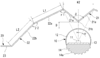
- the pair of surfaces 21 a of the first reflecting surface 21 of the present embodiment has a predetermined light irradiation angle range ⁇ with respect to the optical axis of each LED 11 of the light source 10 (in this embodiment, ⁇ is 15).
- ⁇ is 15
- ⁇ is 60 °
- the width dimension W2 of the first reflecting surface 21 in the Y direction is 23.5 mm
- the distance D between the ridge line 21b of the first reflecting surface 21 and the light transmitting cover 12 of the light source 10 is the width dimension of the light transmitting cover. It is about 1/3 of W1.
- the first surface 22a of the second reflecting surface 22 forms an angle ⁇ 1 ( ⁇ 1 is 110 ° in the present embodiment) with the surface 21a of the first reflecting surface 21, and the second surface 22b is the first surface 22a.
- the angle ⁇ 2 ( ⁇ 2 is 170 ° in the present embodiment)
- the third surface 22c forms an angle ⁇ 3 ( ⁇ 3 is 170 ° in the present embodiment) with the second surface 22b
- the fourth surface 22d is the third surface.
- an angle ⁇ 4 in this embodiment, ⁇ 4 is 170 °).
- the width dimensions L1 to L4 of the first to fourth surfaces 22a to 22d are each 19 mm.
- the illuminating device of this embodiment also has the same effect as the illuminating device of 1st Embodiment.
- a lighting device according to a third embodiment of the present invention will be described with reference to FIGS.
- the angle ⁇ and the width dimension W2 of the first reflecting surface 21 of the reflecting plate 20 are changed in the first embodiment, and other configurations are the same as those in the first embodiment.
- the pair of surfaces 21 a of the first reflecting surface 21 of the present embodiment has a predetermined light irradiation angle range ⁇ (in this embodiment, ⁇ is 30) with respect to the optical axis of each LED 11 of the light source 10.
- ⁇ is 30
- ⁇ is 120 °
- the width dimension W2 of the first reflecting surface 21 in the Y direction is 40.5 mm
- the distance D between the ridge line 21b of the first reflecting surface 21 and the light transmitting cover 12 of the light source 10 is the width dimension of the light transmitting cover. It is about 1/3 of W1.
- the first surface 22a of the second reflecting surface 22 forms an angle ⁇ 1 ( ⁇ 1 is 120 ° in the present embodiment) with the surface 21a of the first reflecting surface 21, and the second surface 22b is the first surface 22a.
- the angle ⁇ 2 ( ⁇ 2 is 170 ° in the present embodiment)
- the third surface 22c forms an angle ⁇ 3 ( ⁇ 3 is 170 ° in the present embodiment) with the second surface 22b
- the fourth surface 22d is the third surface.
- an angle ⁇ 4 in this embodiment, ⁇ 4 is 170 °).
- the width dimensions L1 to L4 of the first to fourth surfaces 22a to 22d are each 19 mm.
- the illuminating device of this embodiment also has the same effect as the illuminating device of 1st Embodiment.
- a lighting device according to a fourth embodiment of the present invention will be described with reference to FIGS.
- the present embodiment is obtained by changing the specification of the second reflecting surface 22 of the reflecting plate 20 in the first embodiment, and the other configuration is the same as that of the first embodiment.
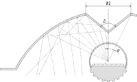
- each LED element 11 In the illumination device configured as described above, light in a light irradiation angle range of 25 ° with respect to the optical axis of each LED element 11 is reflected by the first reflecting surface 21, and most of the reflected light is As shown in FIG. 14, it proceeds toward the outside so as to form an angle (an angle of approximately 70 ° or more) corresponding to the inclination angle of the first reflecting surface 21 with respect to the optical axis of each LED element 11. .
- the illuminating device of this embodiment also has the same effect as the illuminating device of 1st Embodiment.
- a lighting device according to a fifth embodiment of the present invention will be described with reference to FIGS.
- the specification of the first reflecting surface 21 and the angle ⁇ 1 of the second reflecting surface 22 of the reflecting plate 20 are changed in the first embodiment, and other configurations are the same as those in the first embodiment. is there.
- the pair of surfaces 21a of the first reflecting surface 21 of the present embodiment has a predetermined light irradiation angle range ⁇ with respect to the optical axis of each LED 11 of the light source 10 ( ⁇ is 23 in this embodiment).
- ⁇ is 23 in this embodiment.
- ⁇ is 102 °
- Each surface 21a has a width direction inner side surface IS extending in the X direction, and a width direction outer surface OS extending outside in the Y direction with respect to the width direction inner side surface IS and extending in the X direction.
- the ridge line 21b is formed at a portion where the inner surfaces IS in the width direction intersect.
- the width direction outer side surface OS forms a predetermined angle ⁇ ( ⁇ in this embodiment is 190 °) with the width direction inner side surface IS.
- the width dimension W2 in the Y direction of the first reflective surface 21 is 31 mm, and the distance D between the ridge line 21b of the first reflective surface 21 and the translucent cover 12 of the light source 10 is the width dimension W1 of the translucent cover. About 1/3.
- the first surface 22a of the second reflecting surface 22 forms an angle ⁇ 1 ( ⁇ 1 is 110 ° in this embodiment) with the surface 21a of the first reflecting surface 21.
- the illuminating device of this embodiment also has the same effect as the illuminating device of 1st Embodiment.
- a lighting device according to a sixth embodiment of the present invention will be described with reference to FIGS.
- the present embodiment is obtained by changing the specification of the second reflecting surface 22 of the reflecting plate 20 in the first embodiment, and the other configuration is the same as that of the first embodiment.
- Each second reflecting surface 22 of the present embodiment is provided on both outer sides in the Y direction with respect to the first reflecting surface 21, and the first reflecting surface 21 is in a space between the pair of second reflecting surfaces 22. Is arranged.
- Each of the second reflecting surfaces 22 includes a first surface 22a that constitutes a portion closest to the first reflecting surface 21, and a second surface 22b that constitutes a portion that is next closest to the first reflecting surface 21.
- Each of the first and second surfaces 22a and 22b is a flat surface and extends in the X direction.
- the first surface 22a forms an angle ⁇ 1 (in this embodiment, ⁇ 1 is 115 °) with the surface 21a of the first reflecting surface 21, and the second surface 22b forms an angle ⁇ 2 with the first surface 22a (in this embodiment).
- ⁇ 2 is 160 °).
- the width dimensions L1 and L2 of the first and second surfaces 22a and 22b are 38 mm, respectively.
- each LED element 11 In the illumination device configured as described above, light in a light irradiation angle range of 25 ° with respect to the optical axis of each LED element 11 is reflected by the first reflecting surface 21, and most of the reflected light is As shown in FIG. 18, it proceeds toward the outside so as to form an angle (approximately 70 ° or more) corresponding to the inclination angle of the first reflecting surface 21 with respect to the optical axis of each LED element 11. .
- the illuminating device of this embodiment also has the same effect as the illuminating device of 1st Embodiment.
- a lighting device according to a seventh embodiment of the present invention will be described with reference to FIGS.
- the present embodiment is obtained by changing the specification of the second reflecting surface 22 of the reflecting plate 20 in the first embodiment, and the other configuration is the same as that of the first embodiment.
- Each second reflecting surface 22 of the present embodiment is provided on both outer sides in the Y direction with respect to the first reflecting surface 21, and the first reflecting surface 21 is in a space between the pair of second reflecting surfaces 22. Is arranged.
- Each second reflecting surface 22 has a first surface 22a that constitutes a portion closest to the first reflecting surface 21, and the first and second surfaces 22a are flat and extend in the X direction. Yes.
- the first surface 22a forms an angle ⁇ 1 with the surface 21a of the first reflecting surface 21 ( ⁇ 1 is 115 ° in the present embodiment).
- the width dimension L1 of the first surface 22a is 70 mm.
- the illumination device configured as described above, light in a light irradiation angle range of 25 ° with respect to the optical axis of each LED element 11 is reflected by the first reflecting surface 21, and most of the reflected light is As shown in FIG. 20, it proceeds toward the outside so as to make an angle corresponding to the inclination angle of the first reflecting surface 21 with respect to the optical axis of each LED element 11 (an angle of about 70 ° or more). .
- the illuminating device of this embodiment also has the same effect as the illuminating device of 1st Embodiment.
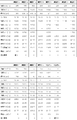
- FIG. 21 shows the experimental results.
- the experimental results show that the lighting devices of the first to seventh embodiments are manufactured, and other lighting devices in which the angle ⁇ , the width dimension W2, and the distance D are changed in the first and second embodiments are manufactured. This is an evaluation of illuminance and illuminance unevenness on the floor as an irradiation position.
- Experimental examples 1 to 7 in FIG. 21 correspond to the first to seventh embodiments, respectively, and experimental example 8 has a width dimension W2 of 29 mm and an angle ⁇ of 20 ° in the first embodiment. Is a width dimension W2 of 21.5 mm and an angle ⁇ of 15 ° in the first embodiment, and Experimental Example 10 is a width dimension W2 of 14.5 mm and an angle ⁇ of 10 ° in the first embodiment.
- the width dimension W2 is 7.2 mm and the angle ⁇ is 5 ° in the first embodiment.
- Experimental Example 12 in FIG. 21 is obtained by making the distance D equal to the width dimension W2 in the second embodiment.
- Comparative Example 1 in FIG. 21 is such that, in the first embodiment, the optical axis of each LED element 10 faces directly below, and most of the light from the light source 10 is directly irradiated onto the floor.
- Example 2 as shown in FIG. 23, a flat reflecting surface is provided instead of the first reflecting surface 21.
- the Experimental Examples 1, 8, 9, 10, and 11 in which the angle ⁇ is 102 ° have less illuminance variation.
- the angle ⁇ is more preferably in the range of 70 ° or more and 115 ° or less in order to reduce the unevenness of the light at the irradiation position, and the range of 90 ° or more and 110 ° or less is the unevenness of the light in the irradiation position. It is considered to be more preferable in terms of reduction.
- each second reflecting surface 22 was composed of a plurality of planes or a single plane. This is because light is emitted radially from each LED element 11 and is reflected by the first reflecting surface 21 which is a flat surface. Therefore, when the second reflecting surface 22 is a concave curved surface, each LED element 11. One reason is that the light from the first reflecting surface 21 tends to be collected by the second reflecting surface 22. In Experimental Example 4, since the average illuminance is higher than that of Comparative Example 1 and the illuminance variation is small, the same effect as in the first embodiment is recognized.
- the angle ⁇ 1 formed between each surface 21a of the first reflecting surface 21 and the vicinity of the first reflecting surface 21 in each second reflecting surface 22 is 110 ° to 130 °. In this range, the above-described effects are confirmed.
- This angle ⁇ 1 can be appropriately changed according to the light source 10, the first reflecting surface 21, and the irradiation range. From the results of Experimental Examples 1 to 12, when the present lighting device is provided on the ceiling for room lighting, the angle ⁇ 1 ⁇ 1 is preferably 100 ° or more and 140 ° or less, and more preferably 110 ° or more and 130 ° or less.
- the second reflecting surfaces 22 are arranged side by side in the Y direction and are continuous with each other at a predetermined angle ⁇ 2 to ⁇ 4. It has been confirmed that the construction of a plurality of planes is advantageous in reducing the unevenness of light at the irradiation position.
- the angles ⁇ 2 to ⁇ 4 are 160 ° to 170 °, and the above-described effects are confirmed in this range.
- the angle ⁇ 1 can be appropriately changed according to the light source 10, the first reflecting surface 21, and the irradiation range. From the results of Experimental Examples 1 to 3, 5, 6, and 8 to 12, the angle ⁇ 1 is 155 ° or more. It is preferable that it is preferably 160 ° or more and 175 ° or less.
- the ridge line 21b is shown in a linear shape.
- the width dimension W3 is preferably 1/5 or less of the width dimension W2, more preferably 1/10 or less, and even more preferably 1/20 or less. That is, the smaller the width dimension W3, the better.
- the ridge line 21b is a flat surface, but it may be a convex curved surface or a concave curved surface.
- the ridgeline 21b and the optical axis of each LED element 11 coincide with each other.
- the ridgeline 21b and the optical axis of each LED element 11 can be shifted in the Y direction. Even in this case, since the light of the predetermined irradiation angle range ⁇ is reflected by the first reflecting surface 21 with respect to the optical axis of each LED element 11, if the angle ⁇ is in accordance with the experimental result of FIG. The same effects as described above are achieved. Further, as shown in FIG.
- the second reflecting surface 22 on the side where the optical axis of each LED element 11 is arranged is arranged. It is also possible to increase the amount of reflected light.
- the light source 10 in which a plurality of LED elements 11 are arranged in a line in the X direction is shown.
- FIG. 26 it is also possible to arrange a plurality of LED elements 11 in a plurality of rows in the X direction.
- the first reflecting surface 21 receives light in a predetermined irradiation angle range ⁇ with respect to the optical axis of the LED elements 11 in each row, and the angle ⁇ is If it is along the experimental result of FIG. 21, the effect similar to the above can be show
- the first reflecting surface 21 receives light in a predetermined irradiation angle range ⁇ with respect to the optical axis of the LED elements 11 in at least one row of each row, and the angle ⁇ is as shown in FIG. As long as it is in accordance with the experimental results, the same effects as described above can be obtained.
- the light source 10 may be configured such that the optical axes of the LED elements 11 in each row are directed in different directions. Even in this case, as long as the light in the predetermined light irradiation angle range ⁇ 2 is received by the pair of surfaces of the first reflecting surface with respect to the center of the light irradiation angle range ⁇ 1 of the light source 10, the same as described above. Has the effect of.
- the range of the angle ⁇ 2 is set to the same setting as the angle ⁇ in each of the above-described embodiments, so that the same effect as that in each of the above-described embodiments is achieved.
- the reference of the angles ⁇ 1 and ⁇ 2 can be, for example, the center position CP of each row as shown in FIG.
- the LED elements 11 in the light source 10 are arranged in a straight line.
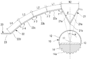
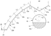
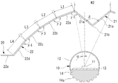
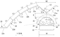
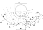
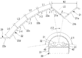
- the LED elements 11 are arranged in the circumferential direction in the light source 10.
- the X direction is a circumferential direction
- the Y direction is a radial direction of the circumference.
- the light source 10 has a ring shape
- the reflection plate 20 also has a ring shape along the light source 10. In this case, the same effects as those of the above embodiments can be obtained.
- each surface 21a of the first reflecting surface 21 is completely flat.
- the radius of curvature is at least twice the width dimension W2, or the depth dimension.
- each surface 21a is assumed to be a flat surface. The reason for this is that even when a curved surface having a slight curvature is used as described above, the angle ⁇ and the like are set in the same manner as in each of the above embodiments, so that the same effect as that in each of the above embodiments can be achieved. Because.
- each of the surfaces 22a to 22d of the second reflecting surface 22 is also formed by a curved surface having a radius of curvature of at least twice the width dimension W2 or a depth dimension DP or a projecting dimension of 1 mm or less. It is assumed that 22a to 22d are flat surfaces.
- the extending direction of the fluorescent tube 31 is the X direction, is orthogonal to the extending direction of the fluorescent tube 31, and the optical axis plane LS of the fluorescent lamp 30 described below.
- a direction orthogonal to the Y direction is taken as a Y direction.
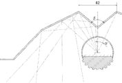
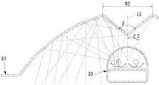
- This illumination device includes a fluorescent lamp 30 and a reflector 20 as shown in FIGS.
- the fluorescent lamp 30 is configured to irradiate light in a predetermined light irradiation angle range ⁇ 1 in a direction (Y direction) orthogonal to the extending direction of the fluorescent tube 31.
- the central surface (surface extending in the X direction) of the light irradiation angle range ⁇ 1 is referred to as an optical axis surface LS of the fluorescent lamp 30.
- the fluorescent lamp 30 is mounted so that the optical axis surface LS faces directly upward when mounted on an indoor ceiling.
- fluorescent lamp 30 it is possible to use, for example, cold cathode tube lamps disclosed in Japanese Patent Application Laid-Open Nos. 2010-251261, 2010-244835, 2010-211961, and the like.
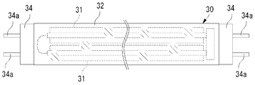
- a plurality of (two in this embodiment) fluorescent tubes 31 composed of cold cathode tubes (CCFL tubes) extending in a predetermined direction (X direction) and extending along each fluorescent tube 31.
- CCFL tubes cold cathode tubes
- Each in-lamp reflector 40 is attached to the case 33 by a fixture (not shown), and each fluorescent tube 31 is also attached to the case 33 by a fixture (not shown).
- Each fluorescent tube 31 is disposed between the in-lamp reflector 40 and the translucent cover 32.
- the width dimension W1 of the translucent cover 32 is 28 mm, but it is also possible to use a translucent cover 32 having a width dimension W1 other than that.
- the fluorescent lamp 30 is of a type in which the light diffusion of each fluorescent tube 31 by the translucent cover 32 is small, but a type in which the light diffusion of each fluorescent tube 31 by the translucent cover 33 is large can also be used. It is.
- a cold cathode tube is used as the fluorescent tube 31, but other fluorescent tubes such as a T4 fluorescent tube and a T5 fluorescent tube can be used.
- the two fluorescent tubes 31 are separately formed. However, the two fluorescent tubes 31 are continuous at one end in the length direction with, for example, a U-shaped fluorescent tube. It is also possible to form it. Even in this case, in this embodiment, it is assumed that the two fluorescent tubes 31 extend in the X direction.
- Each fluorescent tube 31 has a diameter d1 of several millimeters (5 mm in the present embodiment), and is arranged so as to be substantially parallel to each other.
- the case 33 is a cylindrical member made of a metal material such as aluminum and extending in the extending direction of each fluorescent tube 31, and includes an inverter or a PFC (Power Factor Controller, not shown) for supplying power to each fluorescent tube 31 inside. Z).
- Each in-lamp reflecting plate 40 is formed by bending a metal plate such as aluminum and has a first reflecting surface 41 and a second reflecting surface 42.
- each of the reflecting surfaces 41 and 42 is formed to have a rough surface or have irregularities so that the center line average roughness is 0.5 ⁇ m or more.
- the surface of the aluminum plate constituting each of the reflection surfaces 41 and 42 is subjected to rough surface treatment and anodizing treatment by shot blasting or the like so that the center line average roughness is 0.5 ⁇ m or more.
- a plurality of small recesses are formed on the surface of the aluminum plate constituting each of the reflecting surfaces 41 and 42 by embossing or the like, and in order to improve the reflectance on the aluminum surface, glass or plastic
- the translucent material is coated with PVD or the like.
- the first reflecting surface 41 is composed of a pair of surfaces 41a extending in the X direction.
- Each surface 41a is a flat surface, and a convex ridge 41b toward the fluorescent lamp 30 is formed at a portion where the pair of surfaces 41a intersect.
- Each fluorescent tube 31 irradiates light within a light irradiation angle range of 360 ° in a direction orthogonal to the extending direction, and each of the in-lamp reflectors 40 is out of the light irradiated from the corresponding fluorescent tube 31. It receives light in a predetermined light irradiation angle range ⁇ 1.
- the first reflecting surface 41 has an angle ⁇ 2 (in this embodiment, ⁇ 2 is 17 °) with respect to the central surface CS of the predetermined light irradiation angle range ⁇ 1 that is irradiated from the fluorescent tube 31 to each in-lamp reflecting plate 40. )
- the surfaces 41a of the first reflecting surface 41 form an angle ⁇ ( ⁇ is 100 ° in the present embodiment) in the vicinity of the ridge line 41b.
- the width dimension W3 in the Y direction of the first reflecting surface 41 is 3.5 mm
- the distance D1 between the ridge line 41b of the first reflecting surface 41 and the fluorescent tube 31 is the diameter of the fluorescent tube 31. It is about 1/2 of d1.
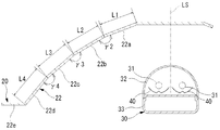
- Each second reflecting surface 42 is provided on both outer sides in the Y direction with respect to the first reflecting surface 41, and the first reflecting surface 41 is arranged in a space between the pair of second reflecting surfaces 42.
- Each of the second reflecting surfaces 42 includes a first surface 42a constituting a portion closest to the first reflecting surface 41, and a second surface 42b constituting a portion next to the first reflecting surface 41, Next, it has the 3rd surface 42c which comprises the part close
- Each of the first to fourth surfaces 42a to 42d is a flat surface and extends in the X direction.
- the first surface 42a forms an angle ⁇ 5 ( ⁇ 5 is 120 ° in this embodiment) with the surface 41a of the first reflecting surface 41
- the second surface 42b forms an angle ⁇ 6 (in this embodiment) with the first surface 42a.
- ⁇ 6 is 170 °
- the third surface 42c is at an angle ⁇ 7 with the second surface 42b (in this embodiment, ⁇ 7 is 170 °)
- the fourth surface 42d is at an angle ⁇ 8 (with ⁇ 8 ( In this embodiment, ⁇ 8 is 170 °.
- the width dimensions L5 to L8 of the first to fourth surfaces 42a to 42d are 2 mm, respectively.
- the fluorescent lamp 30 is attached to the indoor ceiling by inserting the terminal 34a of each base 34 into the socket 100 provided on the indoor ceiling.
- the socket 100 an existing socket for attaching a fluorescent lamp can be used as it is.
- the reflector 20 is the same as that of the first embodiment, and is attached to the indoor ceiling as in the first embodiment. Specifically, when the fluorescent lamp 30 is attached to the socket 100, the reflector 20 is attached to the ceiling of the room so as to be positioned above the fluorescent lamp 30.
- the pair of surfaces 21a of the first reflecting surface 21 of the reflecting plate 20 has a predetermined light irradiation angle range ⁇ 2 ( ⁇ 2 in this embodiment) with respect to the optical axis surface LS of the fluorescent lamp 30.
- ⁇ 2 in this embodiment
- the distance D between the ridge line 21b of the first reflecting surface 21 and the translucent cover 32 of the fluorescent lamp 30 is about 1/3 of the width dimension W2 of the translucent cover 32.
- the light advances toward the outside so as to form an angle corresponding to the inclination angle of the first reflecting surface 21 with respect to the optical axis surface LS of the fluorescent lamp 30 (an angle of about 70 ° or more). Moreover, it has a pair of 2nd reflective surface 22 provided in the both outer sides of the direction which cross
- the first reflecting surface 21 is disposed in the space between the two. For this reason, the light reflected by the first reflecting surface 21 is reflected by the second reflecting surface 22, while the light directly irradiated from the fluorescent lamp 30 is also reflected by the second reflecting surface 22.
- the fluorescent lamp 30 is disposed so that the optical axis surface LS faces directly upward, the first reflecting surface 21 is disposed above the fluorescent lamp 30, and the first reflecting surface 21 is disposed.
- the ridge line 21b is convex downward.
- the first reflecting surface 21 is disposed in the space between the pair of second reflecting surfaces 22. For this reason, the light reflected by the first reflecting surface 21 is further reflected by the second reflecting surface 22, while the light directly irradiated from the fluorescent lamp 30 is also reflected by the second reflecting surface 22, and the second The light reflected by the reflecting surface 22 is irradiated toward an irradiation position such as an indoor floor. Therefore, according to this embodiment, the light from the fluorescent lamp 30 can be efficiently irradiated to the irradiation position such as the floor.
- each of the reflecting surfaces 21 and 22 is formed to have a rough surface or an unevenness by embossing or the like so that the center line average roughness is 0.5 ⁇ m or more.
- the fluorescent lamp 30 is composed of two fluorescent tubes 31, and light is emitted from the two line light sources, but the light from each fluorescent tube 31 is diffused by the reflecting surfaces 21 and 22. .
- the unevenness of the light at the irradiation position is reduced. Is very advantageous.
- the reflecting surfaces 21 and 22 are mirror-finished, for example, and the center line average roughness is about 0.1 ⁇ m, when the light from the fluorescent lamp 30 is reflected by the reflecting surfaces 21 and 22, Not a little light from the lamp 30 is diffused by the reflecting surfaces 21 and 22. For this reason, compared with the case where the light of the fluorescent lamp 30 is directly irradiated to the irradiation position such as the floor, the light from the fluorescent lamp 30 is diffused, and uneven illuminance at the irradiation position can be reduced.
- FIG. 38 shows the experimental results, and shows the results of the same evaluation performed by the same method as in FIG.
- the lighting device of the eighth to fourteenth embodiments was manufactured, and another lighting device having the width dimension W2 and the distance D changed in the eighth embodiment was manufactured.
- the illumination device of the ninth embodiment is obtained by changing the reflection plate 20 to the reflection plate 20 of the second embodiment (see FIGS. 9 and 10) in the eighth embodiment, and the illumination device of the tenth embodiment In the eighth embodiment, the reflection plate 20 is changed to the reflection plate 20 of the third embodiment (see FIGS. 11 and 12), and the illuminating device of the eleventh embodiment replaces the reflection plate 20 in the eighth embodiment.
- the illuminating device of the twelfth embodiment is changed to the reflector 20 of the fourth embodiment (see FIGS. 13 and 14), and the illuminating device of the twelfth embodiment replaces the reflector 20 in the fifth embodiment (FIGS. 15 and 15). 16), the illuminating device of the thirteenth embodiment is changed from the reflecting plate 20 to the reflecting plate 20 of the sixth embodiment (see FIGS. 17 and 18) in the eighth embodiment. 14th implementation Lighting device state is obtained by changing the reflecting plate 20 to the reflection plate 20 of the seventh embodiment (see FIGS. 19 and 20) in the eighth embodiment.
- the optical axis surface LS of the fluorescent lamp 30 faces directly above, and the position of the optical axis surface LS is the first reflecting surface of the reflecting plate 20.
- the distance D between the ridge line 21b of the first reflecting surface 21 of the reflector 20 and the fluorescent tube 31 is about 1/3 of the width W2.
- Experimental examples 13 to 19 in FIG. 38 correspond to the eighth to fourteenth embodiments, respectively, and experimental example 20 is an experiment in which the width dimension W2 is 25 mm and the angle ⁇ 2 is 20 ° in the eighth embodiment.
- Example 21 is an example in which the width dimension W2 is 18 mm and the angle ⁇ 2 is 15 ° in the eighth embodiment
- Experimental Example 22 is an example in which the width dimension W2 is 12 mm and the angle ⁇ 2 is 10 ° in the eighth embodiment.
- the width W2 is 6 mm and the angle ⁇ 2 is 5 ° in the eighth embodiment.
- Experimental Example 24 in FIG. 38 is the distance D made equal to the width dimension W2 in the ninth embodiment.
- Comparative Example 3 in FIG. 38 is such that in the eighth embodiment, the optical axis surface LS of the fluorescent lamp 30 faces directly below, and most of the light from the fluorescent lamp 30 is directly irradiated onto the floor.
- Comparative Example 4 as shown in FIG. 39, a flat reflecting surface is provided in place of the first reflecting surface 21.
- each second reflecting surface 22 was composed of a plurality of planes or a single plane. This is considered to be one of the reasons that the light from the fluorescent lamp 30 tends to be collected by the second reflecting surface 22 when the second reflecting surface 22 is a concave curved surface.
- the average illuminance is higher and the illuminance variation is smaller than that of Comparative Example 4 in Experimental Example 16, the same effects as in the eighth embodiment are recognized.
- an angle ⁇ 1 formed between each surface 21a of the first reflecting surface 21 and the vicinity of the first reflecting surface 21 in each second reflecting surface 22 is 110 ° to 130 °. In this range, the above-described effects are confirmed.
- the angle ⁇ 1 can be appropriately changed according to the fluorescent lamp 30, the first reflecting surface 21, and the irradiation range. However, when the lighting device is provided for indoor lighting, the angle ⁇ 1 is 100 ° or more and 140 ° or less. It is preferable that the angle is 110 ° or more and 130 ° or less.
- the second reflecting surfaces 22 are arranged side by side in the Y direction and are continuous with each other at a predetermined angle ⁇ 2 to ⁇ 4. It has been confirmed that the construction of a plurality of planes is advantageous in reducing the unevenness of light at the irradiation position.
- the angles ⁇ 2 to ⁇ 4 are 160 ° to 170 °, and the above-described effects are confirmed in this range.
- the angle ⁇ 1 can be appropriately changed according to the tendency lamp 30, the first reflecting surface 21, and the irradiation range. From the results of Experimental Examples 13 to 15, 17, 18, and 20 to 24, the angle ⁇ 1 is 155 ° or more. It is preferable that it is 160 ° or more and 175 ° or less.
- the ridgeline 21b is shown in a linear shape, but the ridgeline 21b shown in FIG. 24 is used even in the case where the reflecting plate 21 in which the ridgeline 21b appears in a planar shape having a width dimension W3 is used.
- the width dimension W3 distance between the one surface 21a and the other surface 21a
- the width dimension W3 is preferably 1/5 or less of the width dimension W2, more preferably 1/10 or less, and even more preferably 1/20 or less. That is, the smaller the width dimension W3, the better.
- the ridge line 21b is a flat surface, but it may be a convex curved surface or a concave curved surface.
- the ridgeline 21b and the optical axis plane LS of the tendency lamp 30 are shown to coincide with each other.
- the ridgeline 21b and the optical axis surface LS of the fluorescent lamp 30 can be shifted in the Y direction. Even in this case, since the light in the predetermined irradiation angle range ⁇ 2 is reflected by the first reflecting surface 21 with respect to the optical axis surface LS of the fluorescent lamp 30, if the angle ⁇ 2 is in accordance with the experimental result of FIG. The same effects as described above are obtained. Also, as shown in FIG.
- the second reflecting surface on the side where the optical axis surface LS of the fluorescent lamp 30 is arranged by positively shifting the ridge line 21b and the optical axis surface LS of the fluorescent lamp 30 in the Y direction. It is also possible to increase the amount of reflection of 22 light.
- the one using the fluorescent lamp 30 in which the plurality of fluorescent tubes 31 are arranged in the Y direction is shown. Play.
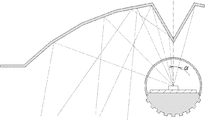
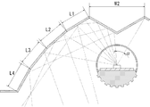
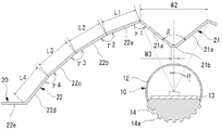
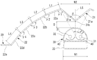
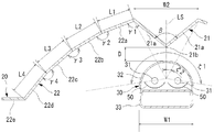
- the fluorescent lamps 31 of the fluorescent lamp 30 are shown as being straight, but as shown in FIG. 42, the fluorescent lamp 30 is ring-shaped and each fluorescent lamp 31 is Even in the case of a ring shape, the same configuration as in the eighth to fourteenth embodiments can be adopted.
- the X direction is a circumferential direction
- the Y method is a radial direction
- the reflector 20 has a ring shape. Even in this case, the same effects as those of the eighth to fourteenth embodiments can be obtained.
- the surfaces 21a of the first reflecting surface 21 are completely flat.
- the radius of curvature is 2 with a width dimension W2.
- each surface 21a is constituted by a curved surface having a depth of DP or more, or a depth dimension DP or a protrusion dimension of 1 mm or less, each surface 21a is assumed to be a flat surface. The reason for this is that even when a curved surface having a slight curvature is used as described above, the angle ⁇ and the like are set in the same manner as in each of the above embodiments, so that the same effect as that in each of the above embodiments can be achieved. Because.
- each of the surfaces 22a to 22d of the second reflecting surface 22 is also formed by a curved surface having a radius of curvature of at least twice the width dimension W2 or a depth dimension DP or a projecting dimension of 1 mm or less. It is assumed that 22a to 22d are flat surfaces.
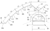
- each reflecting plate 40 of the fluorescent lamp 30 has the first reflecting surface 41 and the second reflecting surface 42.
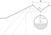
- each reflector 40 of the fluorescent lamp 30 can be replaced with a reflector 50 (fifteenth embodiment).
- the reflection plate 50 has a shape obtained by cutting a part of the cylinder in the circumferential direction.
- the two reflectors 40 of the fluorescent lamp 30 can be replaced with one reflector 60 (the sixteenth embodiment).
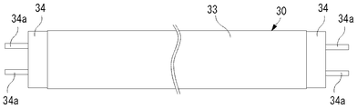
- the fluorescent lamp 30 can be replaced by one fluorescent tube 70 (a seventeenth embodiment).
- the fluorescent tube 70 it is possible to use a cold cathode tube as the fluorescent tube 70, and it is also possible to use a T4 fluorescent tube, a T5 fluorescent tube or another fluorescent tube which is not a cold cathode tube.
- a normal fluorescent tube is used, and the fluorescent tube 70 has a width (diameter) W1 of 28 mm.
- the fluorescent tube 70 irradiates light in a light irradiation angle range of 360 ° in a direction orthogonal to the extending direction.
- light in a predetermined light irradiation angle range ⁇ 2 (in the present embodiment, ⁇ 2 is 28 °) among the light emitted from the fluorescent tube 70 is received by the first reflecting surface 21 of the reflecting plate 20. Yes.
- FIG. 46 shows the experimental results, and shows the results of evaluation by the same method as in FIGS. 21 and 38.
- the illumination devices of the fifteenth to seventeenth embodiments were manufactured, and the illuminance and the unevenness of the illuminance on the floor as the irradiation position were evaluated.
- Experimental examples 25 to 27 in FIG. 46 correspond to the fifteenth to seventeenth embodiments, respectively.
- a reflective surface which is a plane is provided in place of the first reflective surface 21 as in the case of FIG. It is.
- the diameter d2 of the fluorescent tube 70, the distance between the fluorescent tube 70 and the ridge line 21b, the width W2 and the angle ⁇ of the first reflecting surface 21, etc. are the specifications and irradiation position of the fluorescent tube 70.
- the angle ⁇ 2 the angle ⁇ , the distance D, and the angles ⁇ 1 to 4 are in accordance with the experimental results of FIG. 38, the same as in the eighth to fourteenth embodiments.
- the light from the fluorescent tube 70 can be effectively irradiated to the irradiation position.
- the optical axis LS of the fluorescent lamp 30 faces directly below, and most of the light from the fluorescent lamp 30 is directly irradiated onto the floor. Even in this case, the light from each fluorescent tube 31 can be used effectively by the lamp reflector 40 as described above. For this reason, the fluorescent lamp 30 of the eighth embodiment can be used alone as a lighting device.
- the diameter d 1 of the fluorescent tube 31, the distance D 1 between the fluorescent tube 31 and the ridge line 41 b, the width W 3 of the first reflecting surface 41, the angle ⁇ , and the like are the specifications of the fluorescent tube 31 and the fluorescent tube 31.
- the angle ⁇ 2, the angle ⁇ , the distance D1, and the angles ⁇ 5 to 7 of the reflecting plate 40 in the fluorescent lamp 30 are the angle ⁇ 2, the angle ⁇ , the distance D, and the angle ⁇ 1 of the reflecting plate 20 in the illumination device of the eighth embodiment.
- the angle ⁇ 2, the angle ⁇ , the distance D1, and the angles ⁇ 5 to 7 on the reflector 40 of the fluorescent lamp 30 are considered to be replaced with the angle ⁇ 2, the angle ⁇ , the distance D, and the angles ⁇ 1 to 4, and these are the experimental results of FIG.
- the light from the fluorescent tube 31 can be used more effectively, as in the eighth to fourteenth embodiments.
- the lighting device provided on the ceiling of the room is shown.
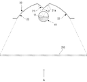
- the lighting device having the structure of each of the above embodiments for a backlight of a signboard or a liquid crystal screen, and cultivate plants. It can also be used as a lighting device for other purposes, and can also be used as a lighting device for other purposes.
- the acrylic plate 200 is illuminated by the light of each LED element 11.
- unevenness in the illuminance of light irradiated on the acrylic plate is reduced, and the amount of light irradiated on the back surface of the acrylic plate 200 can be effectively improved.
- the uneven brightness of the acrylic plate when the acrylic plate is viewed from the A direction can be reduced, and the acrylic plate can be made bright.
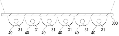
- a plurality of fluorescent tubes 31 extending in a predetermined direction, a plurality of reflecting plates 40 respectively provided on the back side of the plurality of fluorescent tubes 31, and a plurality of fluorescent tubes It is possible to configure a liquid crystal backlight including a diffusion plate 300 provided in front of the tube 31 (eighteenth embodiment). In this case, it is possible to effectively improve the luminance of the liquid crystal and reduce the power used for the backlight for the liquid crystal.
Abstract
In the disclosed illumination device, each LED element (11) is arranged with the optical axis oriented straight up, a first reflective surface (21) is arranged above said LED element, and a ridgeline (21b) of the first reflective surface (21) protrudes downwards. Further, the first reflective surface (21) is arranged in the space between a pair of second reflective surfaces (22), and light reflected by the first reflective surface (21) is reflected again by the second reflective surfaces (22). Light from the LED elements (11) not reflected by the first reflective surface (21) is reflected by the second reflective surface, and the light not reflected by the second reflective surface (22) is irradiated towards an irradiation position on the floor, etc., of a room.
Description
本発明は、LED素子を用いた照明装置に関するものである。
The present invention relates to an illumination device using an LED element.
従来の室内用の照明装置としては、蛍光管と、蛍光管の背面側に配置された傘や反射板とを備え、蛍光管の前面から照射される光が室内に直接照射され、蛍光管の背面側から照射される光が傘や反射板によって反射して室内に補助的に照射されるものが知られている(例えば、実用新案登録第3125998号公報及び特開2008-300230号公報参照。)。
A conventional indoor lighting device includes a fluorescent tube and an umbrella or a reflector disposed on the back side of the fluorescent tube. Light emitted from the front of the fluorescent tube is directly irradiated into the room, and the fluorescent tube It is known that light radiated from the back side is reflected by an umbrella or a reflector and is radiated supplementarily into the room (for example, see Utility Model Registration No. 312998 and JP-A-2008-300230). ).
一方、近年では、省エネルギー化及び長寿命化の観点から、蛍光管を複数のLED素子が並設された直管型の光源に置き換えることが検討されている(例えば、特開2010-113055号公報参照。)。しかしながら、蛍光管は全方位の指向特性を有しているのに対し、LED素子は一定の角度範囲のみに強い光を照射する指向特性を有しているので、単に複数のLED素子を一列に並べただけでは蛍光管の代わりにはならない。このため、複数のLED素子を複数列に並設するとともに、各列のLED素子の光軸を互いにずらした直管型の光源が知られている(例えば、意匠登録第1203169号公報参照。)。
On the other hand, in recent years, from the viewpoint of energy saving and longer life, it has been studied to replace a fluorescent tube with a straight tube type light source in which a plurality of LED elements are arranged in parallel (for example, Japanese Patent Application Laid-Open No. 2010-113055). reference.). However, while fluorescent tubes have omnidirectional directional characteristics, LED elements have directional characteristics that irradiate strong light only in a certain angular range, so a plurality of LED elements are simply arranged in a row. Just arranging them is not a substitute for fluorescent tubes. For this reason, a straight tube type light source in which a plurality of LED elements are arranged side by side and the optical axes of the LED elements in each row are shifted from each other is known (see, for example, Design Registration No. 1203169). .
しかしながら、前述のようにLED素子を複数列に並設する場合でも、蛍光灯のように全方位に亘ってほぼ均一な指向特性となる訳ではなく、各LED素子の一定の照射角度範囲、特に光軸の近傍が他の範囲よりも明るくなることには変わりがない。このため、照射位置において照度のむらが出やすく、蛍光灯からの交換時に不快感を覚える者もいる。
However, even when the LED elements are arranged in a plurality of rows as described above, it does not become almost uniform directivity characteristics in all directions like a fluorescent lamp, and a certain irradiation angle range of each LED element, particularly There is no change in the vicinity of the optical axis being brighter than the other ranges. For this reason, unevenness in illuminance easily occurs at the irradiation position, and some people feel uncomfortable when replacing the fluorescent lamp.
さらに、近年では、省エネルギー化及び長寿命化の観点から、冷陰極管(CCFL管)を用いた直管型の蛍光ランプを通常の蛍光灯の代わりに用いることが検討されている(例えば、特開2010-251261号公報参照。)。この蛍光ランプは、所定方向に延設された複数の冷陰極管と、冷陰極管に沿うように延設された平面状の反射板と、冷陰極管に沿うように延設された透光性カバーとを備え、反射板と透光性カバーとの間に冷陰極管が配置されているものである。
Furthermore, in recent years, from the viewpoint of energy saving and longer life, it has been studied to use a straight tube type fluorescent lamp using a cold cathode tube (CCFL tube) instead of a normal fluorescent lamp (for example, a special fluorescent lamp). (See JP 2010-251261). The fluorescent lamp includes a plurality of cold cathode tubes extending in a predetermined direction, a flat reflector extending along the cold cathode tubes, and a light transmitting member extending along the cold cathode tubes. A cold cathode tube is disposed between the reflector and the translucent cover.
冷陰極管の駆動電力は、直径28mmや32.5mmの通常の蛍光管の駆動電力に比べて少なく、冷陰極管は寿命の面でも通常の蛍光管に比べて優れているので、省エネルギー化及び長寿命化の点で有利である。しかし、冷陰極管の直径は数mm程度であり、その発光量は通常の蛍光管に比べてかなり劣っているので、従来から冷陰極管は室内用照明としては適していないと考えられており、液晶画面のバックライト等の低照度の用途で使用されるに留まっていた。
The driving power of the cold cathode tube is smaller than that of a normal fluorescent tube having a diameter of 28 mm or 32.5 mm, and the cold cathode tube is superior to the normal fluorescent tube in terms of life, so energy saving and This is advantageous in terms of extending the life. However, the cold cathode tube has a diameter of several millimeters and its light emission is considerably inferior to that of a normal fluorescent tube. Therefore, it has been conventionally considered that a cold cathode tube is not suitable for indoor lighting. It has been used only for low-illuminance applications such as LCD screen backlights.
このため、近年では、冷陰極管を用いた直管型の蛍光ランプの発光量を向上するために、冷陰極管自体の発光量の改良について研究・開発が行われている。しかしながら、冷陰極管の発光方式や直径が小さいこと等が要因となり、冷陰極管自体の発光量をなかなか向上することができていない。このため、現在でも、冷陰極管を用いた直管型の蛍光ランプの発光量は通常の蛍光管に比べてかなり劣っている状態である。
For this reason, in recent years, in order to improve the light emission amount of a straight tube type fluorescent lamp using a cold cathode tube, research and development have been conducted on improving the light emission amount of the cold cathode tube itself. However, due to factors such as the light emission method and the diameter of the cold cathode tube, the amount of light emitted from the cold cathode tube itself cannot be improved easily. For this reason, even now, the amount of light emitted by a straight tube type fluorescent lamp using a cold cathode tube is considerably inferior to that of a normal fluorescent tube.
本発明は前記課題に鑑みてなされたものであり、その目的とするところは、省エネルギー化を図ることができ、且つ、照射位置における照度のむらが少ない照明装置を提供することにある。
The present invention has been made in view of the above-described problems, and an object of the present invention is to provide an illuminating device that can save energy and has less uneven illuminance at an irradiation position.
また、本発明の目的とするところは、照射位置における照度を確保しつつ省エネルギー化を図ることができる照明装置を提供することにある。
Also, an object of the present invention is to provide an illumination device that can save energy while ensuring illuminance at an irradiation position.
本発明の照明装置は前記目的を達成するために、所定方向に並設された複数のLED素子と、前記LED素子の並設方向に延在する一対の面から成り、当該一対の面が交わる部分に各LED素子側に向かって凸状の稜線が形成され、各LED素子からの光のうち各LED素子の光軸に対して10°以内の光照射角度範囲の光を受光するように配置され、前記一対の面が前記稜線の近傍で互いに60°以上120°以下の角度をなす第1の反射面と、前記各LED素子の光軸と交差し、且つ、前記LED素子の並設方向と交差する方向において、前記第1の反射面の両外側に設けられた一対の第2の反射面とを備え、当該一対の第2の反射面は、その間の空間に前記第1の反射面が配置され、第1の反射面によって反射される光及び各LED素子から直接照射される光を反射するものである。
In order to achieve the above object, the illumination device of the present invention includes a plurality of LED elements arranged in parallel in a predetermined direction and a pair of surfaces extending in the parallel arrangement direction of the LED elements, and the pair of surfaces intersect. A convex ridge line is formed in the portion toward each LED element side, and is arranged so as to receive light within a light irradiation angle range within 10 ° with respect to the optical axis of each LED element among the light from each LED element. The pair of surfaces intersect each other in the vicinity of the ridge line with the first reflecting surface forming an angle of 60 ° or more and 120 ° or less, the optical axis of each LED element, and the parallel arrangement direction of the LED elements And a pair of second reflecting surfaces provided on both outer sides of the first reflecting surface, and the pair of second reflecting surfaces are arranged in the space between them. Are arranged and the light reflected by the first reflecting surface and each LED element It reflects the light that is directly irradiated from.
このように、各LED素子の光軸に対して10°以内の光照射角度範囲の光が第1の反射面の一対の面によって受光され、該一対の面が交わる部分には各LED素子側に向かって凸状の稜線が形成され、第1の反射面の一対の面は稜線の近傍で互いに60°以上120°以下の角度をなすので、各LED素子からの光が第1の反射面によって反射し、その反射した光の大部分は各LED素子の光軸に対して第1の反射面の傾斜角度に応じた角度(例えば45°以上の角度)をなすように外側に向かって進むことになる。また、第1の反射面の両外側に一対の第2の反射面を有し、該一対の第2の反射面の間の空間に第1の反射面が配置され、第1の反射面によって反射された光が第2の反射面によってさらに反射され、各LED素子からの光のうち第1の反射面に照射されない光が第2の反射面によって反射されるようになっている。
Thus, light within a light irradiation angle range of 10 ° or less with respect to the optical axis of each LED element is received by the pair of surfaces of the first reflecting surface, and the portion where the pair of surfaces intersects each LED element side And a pair of surfaces of the first reflecting surface form an angle of 60 ° to 120 ° with each other in the vicinity of the ridge line, so that the light from each LED element is the first reflecting surface. Most of the reflected light travels outward so as to form an angle corresponding to the inclination angle of the first reflecting surface (for example, an angle of 45 ° or more) with respect to the optical axis of each LED element. It will be. In addition, a pair of second reflecting surfaces are provided on both outer sides of the first reflecting surface, and the first reflecting surface is disposed in a space between the pair of second reflecting surfaces. The reflected light is further reflected by the second reflecting surface, and the light not irradiated on the first reflecting surface among the light from each LED element is reflected by the second reflecting surface.
例えば、この照明装置が室内の天井に取付けられる場合、光軸が真上を向くように各LED素子が配置されるとともに、その上方に第1の反射面が配置され、第1の反射面の稜線が下方に向かって凸状となる。また、一対の第2の反射面の間の空間に第1の反射面が配置され、第1の反射面によって反射された光が第2の反射面によってさらに反射され、各LED素子からの光のうち第1の反射面に照射されない光が第2の反射面によって反射され、第2の反射面によって反射された光が室内の床等の照射位置に向かって照射される。
For example, when this lighting device is attached to a ceiling in a room, each LED element is arranged so that the optical axis faces directly above, and a first reflecting surface is arranged above the LED element, and the first reflecting surface The ridge line is convex downward. In addition, a first reflection surface is disposed in a space between the pair of second reflection surfaces, and light reflected by the first reflection surface is further reflected by the second reflection surface, and light from each LED element. The light which is not irradiated to the 1st reflective surface is reflected by the 2nd reflective surface, and the light reflected by the 2nd reflective surface is irradiated toward irradiation positions, such as an indoor floor.
このように、各LED素子から出る光のうち光軸周りの強い光が第1の反射面によって反射されて、その反射した光の大部分は各LED素子の光軸に対して第1の反射面の傾斜角度に応じた角度をなすように外側に向かって進み、その光が第2の反射面によって床等の照射位置に照射される。このため、第2の反射面の仕様を適宜調整することによって、各LED素子の光が直接的に床等の照射位置に照射される場合と比較し、照射位置における照度のむらを低減することができる。
Thus, the strong light around the optical axis among the light emitted from each LED element is reflected by the first reflecting surface, and most of the reflected light is first reflected with respect to the optical axis of each LED element. The light travels outward so as to form an angle corresponding to the inclination angle of the surface, and the light is irradiated to the irradiation position such as the floor by the second reflecting surface. For this reason, by adjusting the specification of the second reflecting surface as appropriate, it is possible to reduce the unevenness of illuminance at the irradiation position as compared with the case where the light of each LED element is directly applied to the irradiation position such as the floor. it can.
また、室内の天井において光軸が真上を向くように各LED素子が配置されても、各LED素子から出る光のうち光軸周りの強い光が第1の反射面によって反射され、その反射した光が第2の反射面によって床等の照射位置に照射され、各LED素子から第2の反射面に直接照射される光も床等の照射位置に向かって反射する。このため、各LED素子からの光を効率的に床等の照射位置に照射することができる。即ち、照射位置における照度を確保しつつ省エネルギー化を図る上で極めて有利である。
Further, even if each LED element is arranged so that the optical axis faces directly above the indoor ceiling, strong light around the optical axis is reflected by the first reflecting surface among the light emitted from each LED element, and the reflection thereof. The irradiated light is irradiated to the irradiation position such as the floor by the second reflection surface, and the light directly irradiated to the second reflection surface from each LED element is also reflected toward the irradiation position such as the floor. For this reason, the light from each LED element can be efficiently irradiated to irradiation positions, such as a floor. That is, it is extremely advantageous for energy saving while ensuring the illuminance at the irradiation position.
また、本発明の照明装置は、所定方向に並設された複数のLED素子と、透光性材料から成るとともに前記LED素子の並設方向に延在し、前記複数のLED素子を覆うように設けられた透光カバーと、を有し、前記LED素子の並設方向と直交する方向に所定の光照射角度範囲で光を照射する光源と、前記光源のLED素子の並設方向に延在する一対の面から成り、当該一対の面が交わる部分にこの光源側に向かって凸状の稜線が形成され、この光源から照射される光のうち前記光照射角度範囲の中央に対して10°以内の範囲の光を受光するように配置され、前記一対の面が前記稜線の近傍で互いに60°以上120°以下の角度をなす第1の反射面と、前記光源のLED素子の光軸と交差し、且つ、LED素子の並設方向と交差する方向において、前記第1の反射面の両外側に設けられた一対の第2の反射面とを備え、当該一対の第2の反射面は、その間の空間に前記第1の反射面が配置され、前記第1の反射面によって反射される光及び前記光源から直接照射される光を反射するものである。
The lighting device of the present invention is composed of a plurality of LED elements arranged in parallel in a predetermined direction and a translucent material, extends in the direction in which the LED elements are arranged, and covers the plurality of LED elements. A light source that emits light in a predetermined light irradiation angle range in a direction orthogonal to the direction in which the LED elements are arranged, and extends in the direction in which the LED elements of the light source are arranged Convex ridges are formed toward the light source side at the intersection of the pair of surfaces, and 10 ° with respect to the center of the light irradiation angle range of the light emitted from the light source. A first reflecting surface that is disposed so as to receive light within a range, and the pair of surfaces form an angle of 60 ° to 120 ° with each other in the vicinity of the ridgeline, and the optical axis of the LED element of the light source One that intersects and intersects the direction of LED elements And a pair of second reflecting surfaces provided on both outer sides of the first reflecting surface, and the pair of second reflecting surfaces has the first reflecting surface arranged in a space between them, The light reflected by the first reflecting surface and the light directly irradiated from the light source are reflected.
このように、光源の光照射角度範囲の中央に対して10°以内の範囲の光が第1の反射面の一対の面によって受光され、該一対の面が交わる部分には各LED素子側に向かって凸状の稜線が形成され、第1の反射面の一対の面は稜線の近傍で互いに60°以上120°以下の角度をなすので、各LED素子からの光が第1の反射面によって反射し、その反射した光の大部分は各LED素子の光軸に対して第1の反射面の傾斜角度に応じた角度(例えば45°以上の角度)をなすように外側に向かって進むことになる。また、第1の反射面の両外側に一対の第2の反射面を有し、該一対の第2の反射面の間の空間に第1の反射面が配置され、第1の反射面によって反射された光が第2の反射面によってさらに反射され、光源からの光のうち第1の反射面に照射されない光が第2の反射面によって反射されるようになっている。
As described above, light within a range of 10 ° with respect to the center of the light irradiation angle range of the light source is received by the pair of surfaces of the first reflecting surface, and the portion where the pair of surfaces intersects each LED element side. A convex ridge line is formed, and the pair of surfaces of the first reflection surface form an angle of 60 ° or more and 120 ° or less with each other in the vicinity of the ridge line, so that the light from each LED element is reflected by the first reflection surface Most of the reflected light travels outward so as to form an angle corresponding to the inclination angle of the first reflecting surface (for example, an angle of 45 ° or more) with respect to the optical axis of each LED element. become. In addition, a pair of second reflecting surfaces are provided on both outer sides of the first reflecting surface, and the first reflecting surface is disposed in a space between the pair of second reflecting surfaces. The reflected light is further reflected by the second reflecting surface, and light that is not irradiated on the first reflecting surface among the light from the light source is reflected by the second reflecting surface.
例えば、この照明装置が室内の天井に取付けられる場合、光軸が真上を向くように各LED素子が配置されるとともに、その上方に第1の反射面が配置され、第1の反射面の稜線が下方に向かって凸状となる。また、一対の第2の反射面の間の空間に第1の反射面が配置され、第1の反射面によって反射された光が第2の反射面によってさらに反射され、各LED素子からの光のうち第1の反射面に照射されない光が第2の反射面によって反射され、第2の反射面によって反射された光が室内の床等の照射位置に向かって照射される。
For example, when this lighting device is attached to a ceiling in a room, each LED element is arranged so that the optical axis faces directly above, and a first reflecting surface is arranged above the LED element, and the first reflecting surface The ridge line is convex downward. In addition, a first reflection surface is disposed in a space between the pair of second reflection surfaces, and light reflected by the first reflection surface is further reflected by the second reflection surface, and light from each LED element. The light which is not irradiated to the 1st reflective surface is reflected by the 2nd reflective surface, and the light reflected by the 2nd reflective surface is irradiated toward irradiation positions, such as an indoor floor.
このように、光源から出る光のうち光照射範囲中央近傍の強い光が第1の反射面によって反射されて、その反射した光の大部分は各LED素子の光軸に対して第1の反射面の傾斜角度に応じた角度をなすように外側に向かって進み、その光が第2の反射面によって床等の照射位置に照射される。このため、第2の反射面の仕様を適宜調整することによって、各LED素子の光が直接的に床等の照射位置に照射される場合と比較し、照射位置における照度のむらを低減することができる。
As described above, the strong light near the center of the light irradiation range among the light emitted from the light source is reflected by the first reflecting surface, and most of the reflected light is first reflected with respect to the optical axis of each LED element. The light travels outward so as to form an angle corresponding to the inclination angle of the surface, and the light is irradiated to the irradiation position such as the floor by the second reflecting surface. For this reason, by adjusting the specification of the second reflecting surface as appropriate, it is possible to reduce the unevenness of illuminance at the irradiation position as compared with the case where the light of each LED element is directly applied to the irradiation position such as the floor. it can.
また、室内の天井において光軸が真上を向くように各LED素子が配置されても、光源から出る光のうち光照射範囲中央近傍の強い光が第1の反射面によって反射され、その反射した光が第2の反射面によって床等の照射位置に照射され、光源から第2の反射面に直接照射される光も床等の照射位置に向かって反射する。このため、各LED素子からの光を効率的に床等の照射位置に照射することができる。即ち、照射位置における照度を確保しつつ省エネルギー化を図る上で極めて有利である。
Further, even if each LED element is arranged so that the optical axis is directly above the indoor ceiling, strong light in the vicinity of the center of the light irradiation range is reflected by the first reflecting surface among the light emitted from the light source, and the reflection thereof. The irradiated light is irradiated to the irradiation position such as the floor by the second reflecting surface, and the light directly irradiated to the second reflecting surface from the light source is also reflected toward the irradiation position such as the floor. For this reason, the light from each LED element can be efficiently irradiated to irradiation positions, such as a floor. That is, it is extremely advantageous for energy saving while ensuring the illuminance at the irradiation position.
また、本発明の照明装置は、所定方向に並設された複数のLED素子と、透光性材料から成るとともに前記LED素子の並設方向に延在し、前記複数のLED素子を覆うように設けられた透光カバーと、を有し、前記LED素子の並設方向と直交する方向に所定の光照射角度範囲で光を照射する光源と、前記光源のLED素子の並設方向に延在する一対の面から成り、当該一対の面が交わる部分にこの光源側に向かって凸状の稜線が形成され、当該稜線がこの光源の前記光照射角度範囲の略中央に配置され、この一対の面が前記稜線の近傍で互いに60°以上120°以下の角度をなし、LED素子の光軸と直交し、且つ、LED素子の並設方向と直交する方向に所定の幅寸法を有する第1の反射面と、前記光源のLED素子の光軸と交差し、且つ、LED素子の並設方向と交差する方向において、前記第1の反射面の両外側に設けられた一対の第2の反射面とを備え、第1の反射面の前記稜線と光源の前記透光カバーとの距離が前記第1の反射面の前記所定の幅寸法の1倍以下であり、前記一対の第2の反射面は、その間の空間に前記第1の反射面が配置され、前記第1の反射面によって反射される光及び前記光源から直接照射される光を反射するものである。
The lighting device of the present invention is composed of a plurality of LED elements arranged in parallel in a predetermined direction and a translucent material, extends in the direction in which the LED elements are arranged, and covers the plurality of LED elements. A light source that emits light in a predetermined light irradiation angle range in a direction orthogonal to the direction in which the LED elements are arranged, and extends in the direction in which the LED elements of the light source are arranged A ridge line that is convex toward the light source side is formed at a portion where the pair of surfaces intersect, and the ridge line is disposed substantially at the center of the light irradiation angle range of the light source. First surfaces having an angle of 60 ° to 120 ° with each other in the vicinity of the ridgeline, having a predetermined width dimension in a direction orthogonal to the optical axis of the LED elements and orthogonal to the juxtaposed direction of the LED elements Crosses the reflective surface and the optical axis of the LED element of the light source. And a pair of second reflecting surfaces provided on both outer sides of the first reflecting surface in a direction intersecting with the parallel arrangement direction of the LED elements, and the ridgeline of the first reflecting surface and the light source of the light source The distance from the translucent cover is less than or equal to one time the predetermined width dimension of the first reflecting surface, and the pair of second reflecting surfaces is arranged with the first reflecting surface in the space between them, The light reflected by the first reflecting surface and the light directly irradiated from the light source are reflected.
このように、第1の反射面の一対の面が交わる部分には光源の各LED素子側に向かって凸状の稜線が形成され、該稜線が光源の光照射範囲の略中央に配置され、第1の反射面の一対の面は稜線の近傍で互いに60°以上120°以下の角度をなすので、光源の各LED素子からの光が第1の反射面によって反射し、その反射した光の大部分は光源の光軸に対して第1の反射面の傾斜角度に応じた角度(例えば45°以上の角度)をなすように外側に向かって進むことになる。また、第1の反射面の両外側に設けられた一対の第2の反射面を有し、該一対の第2の反射面の間の空間に第1の反射面が配置され、第1の反射面によって反射された光が第2の反射面によってさらに反射され、光源の各LED素子からの光のうち第1の反射面に照射されない光が第2の反射面によって反射されるようになっている。
In this way, a convex ridge line is formed toward the LED element side of the light source at a portion where the pair of surfaces of the first reflecting surface intersect, and the ridge line is disposed at the approximate center of the light irradiation range of the light source, Since the pair of surfaces of the first reflecting surface form an angle of 60 ° to 120 ° in the vicinity of the ridgeline, the light from each LED element of the light source is reflected by the first reflecting surface, and the reflected light Most of the light travels outward so as to form an angle corresponding to the tilt angle of the first reflecting surface (for example, an angle of 45 ° or more) with respect to the optical axis of the light source. The first reflective surface has a pair of second reflective surfaces provided on both outer sides of the first reflective surface, and the first reflective surface is disposed in a space between the pair of second reflective surfaces. The light reflected by the reflecting surface is further reflected by the second reflecting surface, and the light that is not irradiated on the first reflecting surface among the light from each LED element of the light source is reflected by the second reflecting surface. ing.
例えば、この照明装置が室内の天井に取付けられる場合、各LED素子の光軸が上を向くように光源が配置されるとともに、その上方に第1の反射面が配置され、第1の反射面の稜線が下方に向かって凸状となる。また、一対の第2の反射面の間の空間に第1の反射面が配置され、第1の反射面によって反射された光が第2の反射面によってさらに反射され、光源の各LED素子からの光のうち第1の反射面に照射されない光が第2の反射面によって反射され、第2の反射面によって反射された光が室内の床等の所定の照射位置に向かって照射される。
For example, when this lighting device is attached to a ceiling in a room, a light source is disposed so that the optical axis of each LED element faces upward, and a first reflecting surface is disposed above the light source. The ridge line is convex downward. In addition, the first reflecting surface is disposed in a space between the pair of second reflecting surfaces, and the light reflected by the first reflecting surface is further reflected by the second reflecting surface, and from each LED element of the light source The light that is not irradiated on the first reflecting surface is reflected by the second reflecting surface, and the light reflected by the second reflecting surface is irradiated toward a predetermined irradiation position such as an indoor floor.
このように、光源から出る光のうち光照射範囲中央近傍の強い光が第1の反射面によって反射されて、その反射した光の大部分は光源の各LED素子の光軸に対して第1の反射面の傾斜角度に応じた角度をなすように外側に向かって進み、その光が第2の反射面によって床等の所定の照射位置に照射される。このため、第2の反射面の仕様を適宜調整することによって、各LED素子の光が直接的に床等の照射位置に向かって照射される場合と比較し、照射位置における照度のむらを低減することができる。
In this way, strong light near the center of the light irradiation range among the light emitted from the light source is reflected by the first reflecting surface, and most of the reflected light is first with respect to the optical axis of each LED element of the light source. The light advances toward the outside so as to form an angle corresponding to the inclination angle of the reflection surface, and the light is irradiated to a predetermined irradiation position such as a floor by the second reflection surface. For this reason, by adjusting the specification of the second reflecting surface as appropriate, the unevenness of illuminance at the irradiation position is reduced as compared with the case where the light of each LED element is directly irradiated toward the irradiation position such as the floor. be able to.
また、室内の天井において光軸が真上を向くように各LED素子が配置されても、光源から出る光のうち光照射範囲中央近傍の強い光が第1の反射面によって反射され、その反射した光が第2の反射面によって床等の所定の照射位置に照射され、光源から第2の反射面に直接照射される光も床等の所定の照射位置に向かって反射する。このため、光源の各LED素子からの光を効率的に床等の所定の照射位置に照射することができる。即ち、照射位置における照度を確保しつつ省エネルギー化を図る上で極めて有利である。
Further, even if each LED element is arranged so that the optical axis is directly above the indoor ceiling, strong light in the vicinity of the center of the light irradiation range is reflected by the first reflecting surface among the light emitted from the light source, and the reflection thereof. The irradiated light is irradiated to a predetermined irradiation position such as a floor by the second reflecting surface, and the light directly irradiated to the second reflecting surface from the light source is also reflected toward the predetermined irradiation position such as the floor. For this reason, the light from each LED element of a light source can be efficiently irradiated to predetermined irradiation positions, such as a floor. That is, it is extremely advantageous for energy saving while ensuring the illuminance at the irradiation position.
また、本発明の照明装置は、所定方向に延設された蛍光管と、当該蛍光管に沿って延設されたランプ内反射板と、透光性材料から成り前記蛍光管の延設方向に延在している透光カバーとを有し、前記反射板と前記透光カバーとの間に前記蛍光管が配置され、前記蛍光管の延設方向と直交する方向における所定の光照射角度範囲に光を照射する蛍光ランプと、前記蛍光ランプの蛍光管の延設方向に延在する一対の面から成り、当該一対の面が交わる部分に前記蛍光ランプ側に向かって凸状の稜線が形成され、前記蛍光ランプから照射される光のうち前記光照射角度範囲の中央に対して10°以内の範囲の光を受光するように配置され、前記一対の面が前記稜線の近傍で互いに60°以上120°以下の角度をなす第1の反射面と、前記蛍光ランプの前記蛍光管の延設方向と直交する方向において前記第1の反射面の両外側に設けられた一対の第2の反射面とを備え、当該一対の第2の反射面は、その間の空間に前記第1の反射面が配置され、前記第1の反射面によって反射される光及び前記蛍光ランプから直接照射される光を反射するものである。
The lighting device of the present invention comprises a fluorescent tube extending in a predetermined direction, an in-lamp reflector extending along the fluorescent tube, and a translucent material in the extending direction of the fluorescent tube. A predetermined light irradiation angle range in a direction perpendicular to the extending direction of the fluorescent tube, the fluorescent tube being disposed between the reflecting plate and the transparent cover. And a pair of surfaces extending in the extending direction of the fluorescent tube of the fluorescent lamp, and a ridge line convex toward the fluorescent lamp side is formed at the intersection of the pair of surfaces. And arranged so as to receive light within a range of 10 ° with respect to the center of the light irradiation angle range of the light emitted from the fluorescent lamp, and the pair of surfaces are 60 ° to each other in the vicinity of the ridgeline. A first reflection surface having an angle of 120 ° or less and the fluorescent run And a pair of second reflecting surfaces provided on both outer sides of the first reflecting surface in a direction orthogonal to the extending direction of the fluorescent tube, and the pair of second reflecting surfaces is a space between them. The first reflecting surface is disposed on the first reflecting surface to reflect light reflected by the first reflecting surface and light directly emitted from the fluorescent lamp.
このように、第1の反射面の一対の面が交わる部分には蛍光ランプ側に向かって凸状の稜線が形成され、該稜線が蛍光ランプの光照射角度範囲の中央に対して10°以内の範囲の光を受光するように配置され、第1の反射面の一対の面は稜線の近傍で互いに60°以上120°以下の角度をなすので、蛍光ランプからの光が第1の反射面によって反射し、その反射した光の大部分は蛍光ランプの光軸面に対して第1の反射面の傾斜角度に応じた角度(例えば45°以上の角度)をなすように外側に向かって進むことになる。また、第1の反射面の両外側に設けられた一対の第2の反射面を有し、該一対の第2の反射面の間の空間に第1の反射面が配置され、第1の反射面によって反射された光が第2の反射面によってさらに反射され、蛍光ランプから直接照射される光も第2の反射面によって反射されるようになっている。
Thus, a convex ridge line is formed toward the fluorescent lamp side at a portion where the pair of surfaces of the first reflecting surface intersect, and the ridge line is within 10 ° with respect to the center of the light irradiation angle range of the fluorescent lamp. Since the pair of surfaces of the first reflecting surface form an angle of 60 ° to 120 ° in the vicinity of the ridgeline, the light from the fluorescent lamp is arranged to receive the light in the range of Most of the reflected light travels outward so as to form an angle corresponding to the inclination angle of the first reflecting surface (for example, an angle of 45 ° or more) with respect to the optical axis surface of the fluorescent lamp. It will be. The first reflective surface has a pair of second reflective surfaces provided on both outer sides of the first reflective surface, and the first reflective surface is disposed in a space between the pair of second reflective surfaces. The light reflected by the reflecting surface is further reflected by the second reflecting surface, and the light directly irradiated from the fluorescent lamp is also reflected by the second reflecting surface.
例えば、この照明装置が室内の天井に取付けられる場合、光軸面が上を向くように蛍光ランプが配置されるとともに、その上方に第1の反射面が配置され、第1の反射面の稜線が下方に向かって凸状となる。また、一対の第2の反射面の間の空間に第1の反射面が配置され、第1の反射面によって反射された光が第2の反射面によってさらに反射され、蛍光ランプから直接照射される光も第2の反射面によって反射され、第2の反射面によって反射された光が室内の床等の所定の照射位置に向かって照射される。
For example, when this lighting device is attached to a ceiling in a room, a fluorescent lamp is disposed so that the optical axis surface faces upward, a first reflecting surface is disposed above the fluorescent lamp, and a ridgeline of the first reflecting surface Becomes convex downward. The first reflecting surface is disposed in the space between the pair of second reflecting surfaces, and the light reflected by the first reflecting surface is further reflected by the second reflecting surface and directly irradiated from the fluorescent lamp. The reflected light is also reflected by the second reflecting surface, and the light reflected by the second reflecting surface is irradiated toward a predetermined irradiation position such as an indoor floor.
したがって、蛍光ランプからの光を効率的に床等の所定の照射位置に照射することができ、照射位置における照度を確保しつつ省エネルギー化を図る上で極めて有利である。
Therefore, it is possible to efficiently irradiate a predetermined irradiation position such as a floor with light from the fluorescent lamp, which is extremely advantageous in achieving energy saving while ensuring illuminance at the irradiation position.
また、本発明の照明装置は、所定方向に延設され、その延設方向と直交する方向において360°の光照射角度範囲に光を照射する蛍光管と、当該蛍光管に沿って延設された反射板とを有する照明装置であって、前記反射板は、前記蛍光管から照射される光のうち所定の光照射角度範囲の光を受光するものであり、且つ、前記蛍光管の延設方向に延在する一対の面から成り、当該一対の面が交わる部分に前記蛍光管側に向かって凸状の稜線が形成され、前記蛍光管から照射される光のうち前記所定の光照射角度範囲の中央に対して10°以内の範囲の光を受光するように配置され、前記一対の面が前記稜線の近傍で互いに60°以上120°以下の角度をなす第1の反射面と、前記蛍光管の延設方向と直交する方向において前記第1の反射面の両外側に設けられた一対の第2の反射面とを有し、当該一対の第2の反射面は、その間の空間に前記第1の反射面が配置され、前記第1の反射面から反射される光及び前記蛍光管から直接照射される光を反射するものである。
The lighting device of the present invention extends in a predetermined direction and extends along the fluorescent tube that irradiates light in a light irradiation angle range of 360 ° in a direction orthogonal to the extending direction. And a reflector that receives light in a predetermined light irradiation angle range of light emitted from the fluorescent tube, and extends the fluorescent tube. Convex ridges are formed toward the fluorescent tube at the intersection of the pair of surfaces extending in the direction, and the predetermined light irradiation angle of the light irradiated from the fluorescent tube A first reflecting surface disposed so as to receive light in a range within 10 ° with respect to the center of the range, and the pair of surfaces having an angle of 60 ° to 120 ° with each other in the vicinity of the ridgeline; The first reflecting surface in a direction orthogonal to the extending direction of the fluorescent tube A pair of second reflecting surfaces provided on both outer sides, and the pair of second reflecting surfaces are arranged such that the first reflecting surface is disposed in a space between them, and is reflected from the first reflecting surface. The reflected light and the light directly irradiated from the fluorescent tube are reflected.
このように、第1の反射面の一対の面が交わる部分には蛍光管側に向かって凸状の稜線が形成され、該稜線が前記所定の光照射角度範囲の中央に対して10°以内の範囲の光を受光するように配置され、第1の反射面の一対の面は稜線の近傍で互いに60°以上120°以下の角度をなすので、蛍光管からの光が第1の反射面によって反射し、その反射した光の大部分は前記中央面に対して第1の反射面の傾斜角度に応じた角度(例えば45°以上の角度)をなすように外側に向かって進むことになる。また、第1の反射面の両外側に設けられた一対の第2の反射面を有し、該一対の第2の反射面の間の空間に第1の反射面が配置され、第1の反射面によって反射された光が第2の反射面によってさらに反射され、蛍光ランプから直接照射される光も第2の反射面によって反射されるようになっている。
Thus, a convex ridge line is formed toward the fluorescent tube side at a portion where the pair of surfaces of the first reflecting surface intersect, and the ridge line is within 10 ° with respect to the center of the predetermined light irradiation angle range. The pair of surfaces of the first reflecting surface form an angle of 60 ° to 120 ° in the vicinity of the ridge line, so that the light from the fluorescent tube is the first reflecting surface. Most of the reflected light travels outward so as to form an angle corresponding to the inclination angle of the first reflecting surface (for example, an angle of 45 ° or more) with respect to the central surface. . The first reflective surface has a pair of second reflective surfaces provided on both outer sides of the first reflective surface, and the first reflective surface is disposed in a space between the pair of second reflective surfaces. The light reflected by the reflecting surface is further reflected by the second reflecting surface, and the light directly irradiated from the fluorescent lamp is also reflected by the second reflecting surface.
例えば、この照明装置が室内の天井に取付けられる場合、前記中央面が上を向くように蛍光管が配置されるとともに、その上方に第1の反射面が配置され、第1の反射面の稜線が下方に向かって凸状となる。また、一対の第2の反射面の間の空間に第1の反射面が配置され、第1の反射面によって反射された光が第2の反射面によってさらに反射され、蛍光管から直接照射される光も第2の反射面によって反射され、第2の反射面によって反射された光が室内の床等の所定の照射位置に向かって照射される。
For example, when the lighting device is attached to an indoor ceiling, the fluorescent tube is disposed so that the central surface faces upward, the first reflecting surface is disposed above the fluorescent tube, and the ridge line of the first reflecting surface Becomes convex downward. The first reflecting surface is disposed in the space between the pair of second reflecting surfaces, and the light reflected by the first reflecting surface is further reflected by the second reflecting surface and directly irradiated from the fluorescent tube. The reflected light is also reflected by the second reflecting surface, and the light reflected by the second reflecting surface is irradiated toward a predetermined irradiation position such as an indoor floor.
したがって、蛍光管からの光を効率的に床等の所定の照射位置に照射することができ、照射位置における照度を確保しつつ省エネルギー化を図る上で極めて有利である。
Therefore, it is possible to efficiently irradiate a predetermined irradiation position such as a floor with light from the fluorescent tube, which is extremely advantageous in achieving energy saving while ensuring illuminance at the irradiation position.
また、本発明は、所定方向に延設された蛍光管と、当該蛍光管に沿って延設された反射板と、透光性材料から成り前記蛍光管の延設方向に延在している透光カバーとを有し、前記反射板と前記透光カバーとの間に前記蛍光管が配置された蛍光ランプであって、前記反射板は、前記蛍光管の延設方向に延在する一対の面から成り、当該一対の面が交わる部分に前記蛍光管側に向かって凸状の稜線が形成された第1の反射面と、前記蛍光管の延設方向と直交する方向において前記第1の反射面の両側に設けられた一対の第2の反射面とを備え、当該一対の第2の反射面は、その間の空間に前記第1の反射面が配置され、前記第1の反射面によって反射される光及び前記蛍光管から直接照射される光を反射するように構成されている。
The present invention also includes a fluorescent tube extending in a predetermined direction, a reflector extending along the fluorescent tube, and a translucent material and extending in the extending direction of the fluorescent tube. A fluorescent lamp in which the fluorescent tube is disposed between the reflective plate and the transparent cover, the reflective plate extending in the extending direction of the fluorescent tube And a first reflecting surface in which a convex ridge line is formed toward the fluorescent tube side at a portion where the pair of surfaces intersect, and the first reflecting surface in a direction orthogonal to the extending direction of the fluorescent tube. A pair of second reflecting surfaces provided on both sides of the reflecting surface, and the pair of second reflecting surfaces is arranged such that the first reflecting surface is disposed in a space between them. And the light directly irradiated from the fluorescent tube are reflected.
このように、第1の反射面の一対の面が交わる部分には蛍光管側に向かって凸状の稜線が形成されているので、蛍光管からの光が第1の反射面によって反射し、その反射した光の大部分は第1の反射面の傾斜角度に応じた角度をなすように外側に向かって進むことになる。また、第1の反射面の両側に設けられた一対の第2の反射面を有し、該一対の第2の反射面の間の空間に第1の反射面が配置され、第1の反射面によって反射された光が第2の反射面によってさらに反射され、蛍光管から直接照射される光も第2の反射面によって反射されるようになっている。
Thus, since the convex ridge line is formed toward the fluorescent tube side at the portion where the pair of surfaces of the first reflective surface intersect, the light from the fluorescent tube is reflected by the first reflective surface, Most of the reflected light travels outward so as to form an angle corresponding to the inclination angle of the first reflecting surface. The first reflection surface has a pair of second reflection surfaces provided on both sides of the first reflection surface, and the first reflection surface is disposed in a space between the pair of second reflection surfaces. The light reflected by the surface is further reflected by the second reflecting surface, and the light directly irradiated from the fluorescent tube is also reflected by the second reflecting surface.
例えば、この蛍光ランプが室内の天井に取付けられる場合、蛍光管の上方に第1の反射面が配置され、第1の反射面の稜線が下方に向かって凸状となる。また、一対の第2の反射面の間の空間に第1の反射面が配置され、第1の反射面によって反射された光が第2の反射面によってさらに反射され、蛍光管から直接照射される光も第2の反射面によって反射され、第2の反射面によって反射された光が透光カバーを介して室内の床等の所定の照射位置に向かって照射される。
For example, when this fluorescent lamp is mounted on the ceiling of a room, the first reflecting surface is disposed above the fluorescent tube, and the ridge line of the first reflecting surface is convex downward. The first reflecting surface is disposed in the space between the pair of second reflecting surfaces, and the light reflected by the first reflecting surface is further reflected by the second reflecting surface and directly irradiated from the fluorescent tube. The reflected light is also reflected by the second reflecting surface, and the light reflected by the second reflecting surface is irradiated toward a predetermined irradiation position such as an indoor floor through the light transmitting cover.
したがって、蛍光管からの光を効率的に床等の所定の照射位置に照射することができ、照射位置における照度を確保しつつ省エネルギー化を図る上で極めて有利である。
Therefore, it is possible to efficiently irradiate a predetermined irradiation position such as a floor with light from the fluorescent tube, which is extremely advantageous in achieving energy saving while ensuring illuminance at the irradiation position.
本発明によれば、省エネルギー化を図ることができ、且つ、照射位置における照度のむらが少ない照明装置を提供することができる。また、照射位置における照度を確保しつつ省エネルギー化を図ることができる。
According to the present invention, it is possible to provide an illuminating device that can save energy and has less uneven illuminance at the irradiation position. Moreover, energy saving can be achieved while ensuring the illuminance at the irradiation position.
なお、上記した以外の本発明の特徴及び顕著な作用・効果は、この発明の原理を例示する以下の実施形態の説明及び図面を参照することで、当業者にとってより明確となる。
It should be noted that the features of the present invention other than those described above, as well as significant actions and effects, will become clearer to those skilled in the art by referring to the following description of the embodiments and drawings illustrating the principle of the present invention.
本発明の第1実施形態の照明装置を図1~8を参照しながら説明する。本実施形態では、図1、3及び6に示すように、LED素子の並設方向をX方向とし、LED素子の並設方向と直交し且つ光源の光軸と略直交する方向をY方向とする。
The illumination device according to the first embodiment of the present invention will be described with reference to FIGS. In this embodiment, as shown in FIGS. 1, 3 and 6, the direction in which the LED elements are arranged in parallel is the X direction, and the direction perpendicular to the LED elements in the arranged direction and substantially perpendicular to the optical axis of the light source is the Y direction. To do.
この照明装置は、図1~8に示すように、直管型の光源10と反射板20とを備えている。
The lighting device includes a straight tube type light source 10 and a reflector 20 as shown in FIGS.
光源10は、例えば特開2010-192242号公報や特開2010-212043号公報等に開示されている公知の直管型のLED光源を用いることが可能である。本実施形態では、所定方向(X方向)に並設された複数のLED素子11と、合成プラスチックやガラス等の公知の透光性材料から成ると共に、LED素子11の並設方向に延在し、前記複数のLED素子11を覆うように設けられて、LED素子11の並設方向と直交し且つ光源10の光軸と略直交する方向(Y方向)に所定の幅寸法W1を有する透光カバー12と、複数のLED11が実装されている基板13と、基板13におけるLED11の実装面とは反対の面に接触し、光源10の外周面の一部を構成しているヒートシンク14と、光源10の長手方向の両端にそれぞれ設けられた口金15と、各口金15にそれぞれ2本ずつ設けられた端子15aとを有する。本実施形態では、透光カバー12の幅寸法W1は28mmであるが、それ以外の幅寸法W1の透光カバー12を用いることも可能である。また、この光源10は、透光カバー12による各LED素子11の光の拡散が少ないタイプのものであるが、各LED素子11の光の拡散が多いタイプの透光カバーも本実施形態に適用可能である。また、本実施形態ではチップ型のLED素子10を用いているが、砲弾型やその他のタイプのLED素子を用いることも可能である。ヒートシンク14は例えばアルミニウム等の金属材料から成り、光源10の外周面を構成する位置に光源10の長手方向に延びる複数の放熱フィン14aを有する。この光源10は、各口金15の端子15aが室内の天井に設けられたソケット100に差込まれることにより、室内の天井に取付けられる。また、光源10が室内の天井に取付けられる際に、光源10の各LED素子11が真上を向くように取付けられる。即ち、光源10の各LED素子11の光軸が真上を向き、光源10のヒートシンク14が光源10の下側に位置する。ソケット100は蛍光灯を取り付けるための既存のソケットをそのまま使用することが可能であり、口金15又は基板13には交流電流を各LED11に適した直流電流に変換する回路が設けられている。
As the light source 10, a known straight tube type LED light source disclosed in, for example, Japanese Patent Application Laid-Open Nos. 2010-192242 and 2010-212043 can be used. In the present embodiment, the LED elements 11 are arranged in parallel in a predetermined direction (X direction) and a known translucent material such as synthetic plastic or glass, and extend in the direction in which the LED elements 11 are arranged. The translucent light is provided so as to cover the plurality of LED elements 11 and has a predetermined width dimension W1 in a direction (Y direction) orthogonal to the parallel arrangement direction of the LED elements 11 and substantially orthogonal to the optical axis of the light source 10. A cover 12, a substrate 13 on which a plurality of LEDs 11 are mounted, a heat sink 14 that is in contact with the surface of the substrate 13 opposite to the mounting surface of the LEDs 11, and forms a part of the outer peripheral surface of the light source 10; 10 has caps 15 provided at both ends in the longitudinal direction, and two terminals 15a provided at each of the caps 15, respectively. In this embodiment, although the width dimension W1 of the translucent cover 12 is 28 mm, the translucent cover 12 of the other width dimension W1 can also be used. Further, the light source 10 is a type in which the light diffusion of each LED element 11 by the light transmission cover 12 is small, but a light transmission cover of a type in which the light diffusion of each LED element 11 is large is also applied to the present embodiment. Is possible. Further, in the present embodiment, the chip-type LED element 10 is used, but a bullet-type or other types of LED elements can also be used. The heat sink 14 is made of a metal material such as aluminum, for example, and has a plurality of heat radiation fins 14 a extending in the longitudinal direction of the light source 10 at positions that constitute the outer peripheral surface of the light source 10. The light source 10 is attached to the indoor ceiling by inserting the terminal 15a of each base 15 into a socket 100 provided on the indoor ceiling. Further, when the light source 10 is attached to the ceiling in the room, each LED element 11 of the light source 10 is attached so as to face directly above. That is, the optical axis of each LED element 11 of the light source 10 faces directly above, and the heat sink 14 of the light source 10 is positioned below the light source 10. As the socket 100, an existing socket for attaching a fluorescent lamp can be used as it is, and the base 15 or the substrate 13 is provided with a circuit for converting an alternating current into a direct current suitable for each LED 11.
反射板20はアルミニウム等の金属板を折り曲げて形成され、第1の反射面21と一対の第2の反射面22とを有する。本実施形態では、各反射面21,22は中心線平均粗さで0.5μm以上となるように粗面状に、又は凹凸を有するように形成されている。例えば、各反射面21,22を構成するアルミニウム板の表面は、中心線平均粗さで0.5μm以上となるように、ショットブラスト等による粗面状処理及び陽極酸化被膜処理が行われている。他の例では、各反射面21,22を構成するアルミニウム板の表面に、エンボス加工等によって小さな凹部が複数形成されるとともに、アルミニウム表面に、反射率を向上するために、ラス状やプラスチック状の透光性材料がPVD等によりコーティングされる。反射板20は室内の天井に取付けられているので、光源10がソケット100に取付けられた際に、その光源10の上方に位置する。例えば、蛍光灯用の従来の反射板を取外し、その位置に反射板20を取付けることが可能である。
The reflection plate 20 is formed by bending a metal plate such as aluminum and has a first reflection surface 21 and a pair of second reflection surfaces 22. In the present embodiment, each of the reflecting surfaces 21 and 22 is formed to have a rough surface or have irregularities so that the center line average roughness is 0.5 μm or more. For example, the surface of the aluminum plate constituting each of the reflecting surfaces 21 and 22 is subjected to rough surface processing and anodic oxide coating processing such as shot blasting so that the center line average roughness is 0.5 μm or more. . In another example, a plurality of small concave portions are formed on the surface of the aluminum plate constituting each of the reflecting surfaces 21 and 22 by embossing or the like, and a lath shape or a plastic shape is formed on the aluminum surface in order to improve the reflectance. The translucent material is coated with PVD or the like. Since the reflection plate 20 is attached to the ceiling of the room, when the light source 10 is attached to the socket 100, it is positioned above the light source 10. For example, it is possible to remove a conventional reflector for a fluorescent lamp and attach the reflector 20 at that position.
第1の反射面21はX方向に延在する一対の面21aから成る。各面21aは平面から成り、一対の面21aが交わる部分に光源10のLED素子11側に向かって凸状の稜線21bが形成されている。第1の反射面21の一対の面21aは、図1及び2に示すように、光源10の各LED素子11の光軸に対して所定の光照射角度範囲α(本実施形態ではαは25°)の光を受光するように配置され、稜線21bの近傍で互いに角度β(本実施形態ではβは102°)をなす。尚、一対の面21aはY方向における前記所定の光照射角度範囲αの光を受光するように配置されていれば良い。また、本実施形態では、第1の反射面21のY方向における幅寸法W2は36mmである。本実施形態では、複数のLED素子11が一列に並んでおり、光源10のY方向における光照射範囲の中央はLED素子11の光軸と一致している。このため、第1の反射面21の稜線21bは光源10のY方向における光照射範囲の中央に配置されている。また、第1の反射面21の稜線21bと光源10の透光カバー12との距離Dは第1反射面W2の幅寸法W2の1/3程度である。
The first reflecting surface 21 is composed of a pair of surfaces 21a extending in the X direction. Each surface 21a is a flat surface, and a convex ridge line 21b toward the LED element 11 side of the light source 10 is formed at a portion where the pair of surfaces 21a intersect. As shown in FIGS. 1 and 2, the pair of surfaces 21 a of the first reflecting surface 21 has a predetermined light irradiation angle range α (in this embodiment, α is 25) with respect to the optical axis of each LED element 11 of the light source 10. Are arranged so as to receive light at an angle β, and form an angle β (in the present embodiment, β is 102 °) in the vicinity of the ridge line 21b. The pair of surfaces 21a may be disposed so as to receive light in the predetermined light irradiation angle range α in the Y direction. In the present embodiment, the width dimension W2 of the first reflecting surface 21 in the Y direction is 36 mm. In the present embodiment, the plurality of LED elements 11 are arranged in a line, and the center of the light irradiation range in the Y direction of the light source 10 coincides with the optical axis of the LED element 11. For this reason, the ridge line 21 b of the first reflecting surface 21 is arranged at the center of the light irradiation range in the Y direction of the light source 10. The distance D between the ridge line 21b of the first reflecting surface 21 and the light transmitting cover 12 of the light source 10 is about 1/3 of the width dimension W2 of the first reflecting surface W2.
各第2の反射面22は第1の反射面21に対してY方向の両外側に設けられ、当該一対の第2の反射面22の間の空間に第1の反射面21が配置されている。各第2の反射面22は、第1の反射面21に最も近い部分を構成する第1の面22aと、次に第1の反射面21に近い部分を構成する第2の面22bと、次に第1の反射面21に近い部分を構成する第3の面22cと、最も第1の反射面21から遠い部分を構成する第4の面22dとを有する。第1~第4の面22a~22dはそれぞれ平面から成り、X方向に延在している。第4の面22dの外端にはフランジ部23が設けられ、フランジ部23は室内の天井への取付け用に設けられている。第1の面22aは第1の反射面21の面21aと角度γ1(本実施形態ではγ1は120°)をなし、第2の面22bは第1の面22aと角度γ2(本実施形態ではγ2は170°)をなし、第3の面22cは第2の面22bと角度γ3(本実施形態ではγ3は170°)をなし、第4の面22dは第3の面22cと角度γ4(本実施形態ではγ4は170°)をなす。また、本実施形態では、第1~第4の面22a~22dの幅寸法L1~L4はそれぞれ19mmである。
Each second reflecting surface 22 is provided on both outer sides in the Y direction with respect to the first reflecting surface 21, and the first reflecting surface 21 is arranged in a space between the pair of second reflecting surfaces 22. Yes. Each of the second reflecting surfaces 22 includes a first surface 22a that constitutes a portion closest to the first reflecting surface 21, a second surface 22b that constitutes a portion next to the first reflecting surface 21, and Next, it has the 3rd surface 22c which comprises the part close | similar to the 1st reflective surface 21, and the 4th surface 22d which comprises the part farthest from the 1st reflective surface 21. FIG. Each of the first to fourth surfaces 22a to 22d is a flat surface and extends in the X direction. A flange portion 23 is provided at the outer end of the fourth surface 22d, and the flange portion 23 is provided for mounting to the indoor ceiling. The first surface 22a forms an angle γ1 (γ1 is 120 ° in the present embodiment) with the surface 21a of the first reflecting surface 21, and the second surface 22b forms an angle γ2 with the first surface 22a (in the present embodiment). γ2 forms 170 °), the third surface 22c forms an angle γ3 with the second surface 22b (in this embodiment, γ3 is 170 °), and the fourth surface 22d forms an angle γ4 with the third surface 22c. In this embodiment, γ4 is 170 °. In the present embodiment, the width dimensions L1 to L4 of the first to fourth surfaces 22a to 22d are each 19 mm.
以上のように、この照明装置は、各LED素子11の光軸に対して25°の光照射角度範囲の光が第1の反射面21の一対の面21aに照射され、当該一対の面21aが交わる部分には各LED素子11側に向かって凸状の稜線21bが形成され、第1の反射面21の一対の面21aは稜線21bの近傍で互いに102°の角度をなす。このため、各LED素子11からの光が第1の反射面21によって反射し、その反射した光の大部分は、図8に示すように、各LED素子11の光軸に対して第1の反射面21の傾斜角度に応じた角度(おおよそ70°以上の角度)をなすように外側に向かって進むことになる。また、第1の反射面21に対してLED素子11の光軸と交差する方向の両外側に設けられた一対の第2の反射面22を有し、当該一対の第2の反射面22の間の空間に第1の反射面21が配置され、第1の反射面21によって反射された光が第2の反射面22によってさらに反射され、光源10からの光のうち第1の反射面に照射されない光が第2の反射面によって反射される。
As described above, in this illuminating device, light in a light irradiation angle range of 25 ° with respect to the optical axis of each LED element 11 is applied to the pair of surfaces 21a of the first reflecting surface 21, and the pair of surfaces 21a. Convex ridgelines 21b are formed at the intersections of the LED elements 11 and the pair of surfaces 21a of the first reflecting surface 21 form an angle of 102 ° in the vicinity of the ridgelines 21b. Therefore, the light from each LED element 11 is reflected by the first reflecting surface 21, and most of the reflected light is first with respect to the optical axis of each LED element 11 as shown in FIG. 8. It proceeds toward the outside so as to form an angle corresponding to the inclination angle of the reflecting surface 21 (an angle of approximately 70 ° or more). Moreover, it has a pair of 2nd reflective surface 22 provided in the both outer sides of the direction which cross | intersects the optical axis of the LED element 11 with respect to the 1st reflective surface 21, The first reflection surface 21 is disposed in the space between, the light reflected by the first reflection surface 21 is further reflected by the second reflection surface 22, and the light from the light source 10 is reflected on the first reflection surface. Light that is not irradiated is reflected by the second reflecting surface.
また、光軸が真上を向くように各LED素子11が配置されるとともに、その上方に第1の反射面21が配置され、第1の反射面21の稜線21bが下方に向かって凸状となっている。また、一対の第2の反射面22の間の空間に第1の反射面21が配置され、第1の反射面21によって反射された光が第2の反射面22によってさらに反射され、各LED素子11からの光のうち第1の反射面21に照射されない光が第2の反射面によって反射され、第2の反射面22によって反射された光が室内の床等の照射位置に向かって照射される。
In addition, each LED element 11 is arranged so that the optical axis faces directly above, the first reflecting surface 21 is arranged above the LED element 11, and the ridge line 21b of the first reflecting surface 21 is convex downward. It has become. In addition, the first reflecting surface 21 is disposed in the space between the pair of second reflecting surfaces 22, and the light reflected by the first reflecting surface 21 is further reflected by the second reflecting surface 22, and each LED Of the light from the element 11, the light not irradiated on the first reflecting surface 21 is reflected by the second reflecting surface, and the light reflected by the second reflecting surface 22 is irradiated toward the irradiation position such as the indoor floor. Is done.
このように、光源10の光照射範囲中央近傍の強い光、つまり本実施形態の場合は各LED素子11の光軸周りの強い光が第1の反射面21によって反射され、その反射した光の大部分は各LED素子11の光軸に対して第1の反射面21の傾斜角度に応じた角度をなすように外側に向かって進み、その光が第2の反射面22によって床等の照射位置に照射される。このため、各LED素子11の光が直接的に床等の照射位置に照射される場合と比較し、照射位置における照度のむらを低減することができる。
As described above, strong light near the center of the light irradiation range of the light source 10, that is, strong light around the optical axis of each LED element 11 in the present embodiment is reflected by the first reflecting surface 21, and the reflected light Most of the light travels outward so as to form an angle corresponding to the inclination angle of the first reflecting surface 21 with respect to the optical axis of each LED element 11, and the light is irradiated on the floor or the like by the second reflecting surface 22. The position is irradiated. For this reason, compared with the case where the light of each LED element 11 is directly irradiated to irradiation positions, such as a floor, the nonuniformity of the illumination intensity in an irradiation position can be reduced.
また、室内の天井において光軸が真上を向くように各LED素子11が配置されても、光源10の光照射範囲中央近傍の強い光、つまり本実施形態の場合は各LED素子11から出る光のうち光軸周りの強い光が第1の反射面21によって反射され、その反射した光が第2の反射面22によって床等の照射位置に向かって反射され、光源10から第2の反射面22に直接照射される光も床等の照射位置に向かって反射する。このため、光源10の各LED素子11からの光を効率的に床等の照射位置に照射することができる。
Moreover, even if each LED element 11 is arranged so that the optical axis faces directly above the ceiling of the room, strong light near the center of the light irradiation range of the light source 10, that is, in the case of the present embodiment, it exits from each LED element 11. Of the light, strong light around the optical axis is reflected by the first reflecting surface 21, and the reflected light is reflected by the second reflecting surface 22 toward the irradiation position such as the floor and the second reflection from the light source 10. The light directly irradiated on the surface 22 is also reflected toward the irradiation position such as the floor. For this reason, the light from each LED element 11 of the light source 10 can be efficiently irradiated to an irradiation position such as a floor.
また、本実施形態では、光源10の各LED素子11の光軸が上方を向き、光源10において各LED素子11の下側に各LED素子11の温度上昇を防止するためのヒートシンク14が配置されている。即ち、光源10において反射板20における第1の反射面21側に各LED素子11が配置され、第1の反射面21から離れた側にヒートシンク14が配置されているので、ヒートシンク14に室内の空気が当たりやすくなり、放熱を効率的に行うことができる。
Further, in the present embodiment, the optical axis of each LED element 11 of the light source 10 faces upward, and a heat sink 14 for preventing a temperature rise of each LED element 11 in the light source 10 is disposed below the LED element 11. ing. That is, in the light source 10, each LED element 11 is disposed on the first reflecting surface 21 side of the reflecting plate 20, and the heat sink 14 is disposed on the side away from the first reflecting surface 21. It becomes easy to hit air, and heat can be efficiently dissipated.
また、本実施形態では、各反射面21,22が中心線平均粗さで0.5μm以上となるように粗面状に、又はエンボス加工等によって凹凸を有するように形成されている。このため、光源10が点光源であるLED素子11の集合であり、各LED素子11は光の指向性が強いものであるが、各反射面21,22によって各LED素子11からの光が拡散される。特に、各LED素子11の光軸周りの強い光は第1の反射面21及び第2の反射面22の両方によって反射されて照射位置に照射されるので、照射位置の光のむらを低減する上で極めて有利である。
Further, in this embodiment, each of the reflecting surfaces 21 and 22 is formed to have a rough surface or an unevenness by embossing or the like so that the center line average roughness is 0.5 μm or more. For this reason, the light source 10 is a set of LED elements 11 that are point light sources, and each LED element 11 has a strong directivity of light, but the light from each LED element 11 is diffused by the reflecting surfaces 21 and 22. Is done. In particular, since the strong light around the optical axis of each LED element 11 is reflected by both the first reflecting surface 21 and the second reflecting surface 22 and irradiated to the irradiation position, the unevenness of the light at the irradiation position is reduced. Is very advantageous.
尚、各反射面21,22が例えば鏡面仕上げされて中心線平均粗さが0.1μm程度である場合でも、各LED素子11からの光が各反射面21,22によって反射される際に、各LED素子11からの光が少なからず各反射面21,22によって拡散される。このため、各LED素子11の光が直接的に床等の照射位置に照射される場合と比較して各LED素子11からの光が拡散され、照射位置における照度のむらを低減することができる。
Even when each of the reflecting surfaces 21 and 22 is mirror-finished and the center line average roughness is about 0.1 μm, when the light from each LED element 11 is reflected by each of the reflecting surfaces 21 and 22, Not a little light from each LED element 11 is diffused by each reflecting surface 21, 22. For this reason, compared with the case where the light of each LED element 11 is directly irradiated to irradiation positions, such as a floor, the light from each LED element 11 is spread | diffused, and the nonuniformity of the illumination intensity in an irradiation position can be reduced.
本発明の第2実施形態の照明装置を図9及び10を参照しながら説明する。本実施形態は、第1実施形態において反射板20の第1の反射面21の角度β、幅寸法W2、及び第2の反射面22の角度γ1を変更したものであり、その他の構成は第1実施形態と同様である。
A lighting device according to a second embodiment of the present invention will be described with reference to FIGS. In the present embodiment, the angle β, the width dimension W2, and the angle γ1 of the second reflecting surface 22 of the first reflecting surface 21 of the reflecting plate 20 are changed in the first embodiment. This is the same as in the first embodiment.
本実施形態の第1の反射面21の一対の面21aは、図9に示すように、光源10の各LED11の光軸に対して所定の光照射角度範囲α(本実施形態ではαは15°)の光を受光するように配置され、稜線21bの近傍で互いに角度β(本実施形態ではβは60°)をなす。また、第1の反射面21のY方向における幅寸法W2は23.5mmであり、第1の反射面21の稜線21bと光源10の透光カバー12との距離Dは透光カバーの幅寸法W1の1/3程度である。
As shown in FIG. 9, the pair of surfaces 21 a of the first reflecting surface 21 of the present embodiment has a predetermined light irradiation angle range α with respect to the optical axis of each LED 11 of the light source 10 (in this embodiment, α is 15). Are arranged so as to receive light at an angle β, and form an angle β (in the present embodiment, β is 60 °) in the vicinity of the ridge line 21b. The width dimension W2 of the first reflecting surface 21 in the Y direction is 23.5 mm, and the distance D between the ridge line 21b of the first reflecting surface 21 and the light transmitting cover 12 of the light source 10 is the width dimension of the light transmitting cover. It is about 1/3 of W1.
第2の反射面22の第1の面22aは第1の反射面21の面21aと角度γ1(本実施形態ではγ1は110°)をなし、第2の面22bは第1の面22aと角度γ2(本実施形態ではγ2は170°)をなし、第3の面22cは第2の面22bと角度γ3(本実施形態ではγ3は170°)をなし、第4の面22dは第3の面22cと角度γ4(本実施形態ではγ4は170°)をなす。また、本実施形態では、第1~第4の面22a~22dの幅寸法L1~L4はそれぞれ19mmである。
The first surface 22a of the second reflecting surface 22 forms an angle γ1 (γ1 is 110 ° in the present embodiment) with the surface 21a of the first reflecting surface 21, and the second surface 22b is the first surface 22a. The angle γ2 (γ2 is 170 ° in the present embodiment), the third surface 22c forms an angle γ3 (γ3 is 170 ° in the present embodiment) with the second surface 22b, and the fourth surface 22d is the third surface. And an angle γ4 (in this embodiment, γ4 is 170 °). In the present embodiment, the width dimensions L1 to L4 of the first to fourth surfaces 22a to 22d are each 19 mm.
このように構成されている場合でも、各LED素子11の光軸に対して15°の光照射角度範囲の光が第1の反射面21によって反射し、その反射した光の大部分が、図10に示すように、各LED素子11の光軸に対して第1の反射面21の傾斜角度に応じた角度(おおよそ45°以上の角度)をなすように外側に向かって進むことになる。このため、本実施形態の照明装置も第1実施形態の照明装置と同様の作用効果を奏する。
Even in such a configuration, light in a light irradiation angle range of 15 ° with respect to the optical axis of each LED element 11 is reflected by the first reflecting surface 21, and most of the reflected light is shown in FIG. As shown in FIG. 10, the light advances toward the outside so as to form an angle corresponding to the inclination angle of the first reflecting surface 21 with respect to the optical axis of each LED element 11 (an angle of approximately 45 ° or more). For this reason, the illuminating device of this embodiment also has the same effect as the illuminating device of 1st Embodiment.
本発明の第3実施形態の照明装置を図11及び12を参照しながら説明する。本実施形態は、第1実施形態において反射板20の第1の反射面21の角度β及び幅寸法W2を変更したものであり、その他の構成は第1実施形態と同様である。
A lighting device according to a third embodiment of the present invention will be described with reference to FIGS. In the present embodiment, the angle β and the width dimension W2 of the first reflecting surface 21 of the reflecting plate 20 are changed in the first embodiment, and other configurations are the same as those in the first embodiment.
本実施形態の第1の反射面21の一対の面21aは、図11に示すように、光源10の各LED11の光軸に対して所定の光照射角度範囲α(本実施形態ではαは30°)の光を受光するように配置され、稜線21bの近傍で互いに角度β(本実施形態ではβは120°)をなす。また、第1の反射面21のY方向における幅寸法W2は40.5mmであり、第1の反射面21の稜線21bと光源10の透光カバー12との距離Dは透光カバーの幅寸法W1の1/3程度である。
As shown in FIG. 11, the pair of surfaces 21 a of the first reflecting surface 21 of the present embodiment has a predetermined light irradiation angle range α (in this embodiment, α is 30) with respect to the optical axis of each LED 11 of the light source 10. Are arranged so as to receive light at an angle β (in the present embodiment, β is 120 °) in the vicinity of the ridge line 21b. The width dimension W2 of the first reflecting surface 21 in the Y direction is 40.5 mm, and the distance D between the ridge line 21b of the first reflecting surface 21 and the light transmitting cover 12 of the light source 10 is the width dimension of the light transmitting cover. It is about 1/3 of W1.
第2の反射面22の第1の面22aは第1の反射面21の面21aと角度γ1(本実施形態ではγ1は120°)をなし、第2の面22bは第1の面22aと角度γ2(本実施形態ではγ2は170°)をなし、第3の面22cは第2の面22bと角度γ3(本実施形態ではγ3は170°)をなし、第4の面22dは第3の面22cと角度γ4(本実施形態ではγ4は170°)をなす。また、本実施形態では、第1~第4の面22a~22dの幅寸法L1~L4はそれぞれ19mmである。
The first surface 22a of the second reflecting surface 22 forms an angle γ1 (γ1 is 120 ° in the present embodiment) with the surface 21a of the first reflecting surface 21, and the second surface 22b is the first surface 22a. The angle γ2 (γ2 is 170 ° in the present embodiment), the third surface 22c forms an angle γ3 (γ3 is 170 ° in the present embodiment) with the second surface 22b, and the fourth surface 22d is the third surface. And an angle γ4 (in this embodiment, γ4 is 170 °). In the present embodiment, the width dimensions L1 to L4 of the first to fourth surfaces 22a to 22d are each 19 mm.
このように構成されている場合でも、各LED素子11の光軸に対して30°の光照射角度範囲の光が第1の反射面21によって反射し、その反射した光の大部分が、図12に示すように、各LED素子11の光軸に対して第1の反射面21の傾斜角度に応じた角度(おおよそ65°以上の角度)をなすように外側に向かって進むことになる。このため、本実施形態の照明装置も第1実施形態の照明装置と同様の作用効果を奏する。
Even in such a configuration, light in a light irradiation angle range of 30 ° with respect to the optical axis of each LED element 11 is reflected by the first reflecting surface 21, and most of the reflected light is shown in FIG. As shown in FIG. 12, it proceeds toward the outside so as to form an angle corresponding to the inclination angle of the first reflecting surface 21 with respect to the optical axis of each LED element 11 (an angle of approximately 65 ° or more). For this reason, the illuminating device of this embodiment also has the same effect as the illuminating device of 1st Embodiment.
本発明の第4実施形態の照明装置を図13及び14を参照しながら説明する。本実施形態は、第1実施形態において反射板20の第2の反射面22の仕様を変更したものであり、その他の構成は第1実施形態と同様である。
A lighting device according to a fourth embodiment of the present invention will be described with reference to FIGS. The present embodiment is obtained by changing the specification of the second reflecting surface 22 of the reflecting plate 20 in the first embodiment, and the other configuration is the same as that of the first embodiment.
本実施形態の各第2の反射面22は第1の反射面21に対してY方向の両外側に設けられ、該一対の第2の反射面22の間の空間に第1の反射面21が配置されている。各第2の反射面22はX方向に延びる円筒の内周面の周方向の一部によって形成されている。各第1の面22aは各第2の反射面22とそれぞれ角度γ1(本実施形態ではγ1は130°)をなす。
Each second reflecting surface 22 of the present embodiment is provided on both outer sides in the Y direction with respect to the first reflecting surface 21, and the first reflecting surface 21 is in a space between the pair of second reflecting surfaces 22. Is arranged. Each second reflecting surface 22 is formed by a portion of the inner peripheral surface of a cylinder extending in the X direction in the circumferential direction. Each first surface 22a forms an angle γ1 (in this embodiment, γ1 is 130 °) with each second reflecting surface 22.
以上のように構成された照明装置も、各LED素子11の光軸に対して25°の光照射角度範囲の光が第1の反射面21によって反射し、その反射した光の大部分が、図14に示すように、各LED素子11の光軸に対して第1の反射面21の傾斜角度に応じた角度(おおよそ70°以上の角度)をなすように外側に向かって進むことになる。また、第1の反射面21に対してLED素子11の光軸と交差する方向の両外側に設けられた一対の第2の反射面22を有し、該一対の第2の反射面22の間の空間に第1の反射面21が配置され、第1の反射面21によって反射された光が第2の反射面によってさらに反射され、光源10からの光のうち第1の反射面に照射されない光が第2の反射面によって反射される。このため、本実施形態の照明装置も第1実施形態の照明装置と同様の作用効果を奏する。
In the illumination device configured as described above, light in a light irradiation angle range of 25 ° with respect to the optical axis of each LED element 11 is reflected by the first reflecting surface 21, and most of the reflected light is As shown in FIG. 14, it proceeds toward the outside so as to form an angle (an angle of approximately 70 ° or more) corresponding to the inclination angle of the first reflecting surface 21 with respect to the optical axis of each LED element 11. . Moreover, it has a pair of 2nd reflective surface 22 provided in the both outer sides of the direction which cross | intersects the optical axis of the LED element 11 with respect to the 1st reflective surface 21, and this pair of 2nd reflective surface 22 of The first reflection surface 21 is disposed in the space between the light, the light reflected by the first reflection surface 21 is further reflected by the second reflection surface, and the first reflection surface is irradiated among the light from the light source 10. Unapplied light is reflected by the second reflecting surface. For this reason, the illuminating device of this embodiment also has the same effect as the illuminating device of 1st Embodiment.
本発明の第5実施形態の照明装置を図15及び16を参照しながら説明する。本実施形態は、第1実施形態において反射板20の第1の反射面21の仕様及び第2の反射面22の角度γ1を変更したものであり、その他の構成は第1実施形態と同様である。
A lighting device according to a fifth embodiment of the present invention will be described with reference to FIGS. In the present embodiment, the specification of the first reflecting surface 21 and the angle γ1 of the second reflecting surface 22 of the reflecting plate 20 are changed in the first embodiment, and other configurations are the same as those in the first embodiment. is there.
本実施形態の第1の反射面21の一対の面21aは、図11に示すように、光源10の各LED11の光軸に対して所定の光照射角度範囲α(本実施形態ではαは23°)の光を受光するように配置され、稜線21bの近傍で互いに角度β(本実施形態ではβは102°)をなす。各面21aは、X方向に延在する幅方向内側面ISと、幅方向内側面ISに対してY方向の外側に設けられてX方向に延在する幅方向外側面OSとを有し、各幅方向内側面ISが交わる部分に前記稜線21bが形成されている。また、幅方向外側面OSは幅方向内側面ISと所定の角度δ(本実施形態ではδは190°)をなす。また、第1の反射面21のY方向における幅寸法W2は31mmであり、第1の反射面21の稜線21bと光源10の透光カバー12との距離Dは透光カバーの幅寸法W1の1/3程度である。
As shown in FIG. 11, the pair of surfaces 21a of the first reflecting surface 21 of the present embodiment has a predetermined light irradiation angle range α with respect to the optical axis of each LED 11 of the light source 10 (α is 23 in this embodiment). Are arranged so as to receive light at an angle β, and form an angle β (in the present embodiment, β is 102 °) in the vicinity of the ridge line 21b. Each surface 21a has a width direction inner side surface IS extending in the X direction, and a width direction outer surface OS extending outside in the Y direction with respect to the width direction inner side surface IS and extending in the X direction. The ridge line 21b is formed at a portion where the inner surfaces IS in the width direction intersect. Further, the width direction outer side surface OS forms a predetermined angle δ (δ in this embodiment is 190 °) with the width direction inner side surface IS. Moreover, the width dimension W2 in the Y direction of the first reflective surface 21 is 31 mm, and the distance D between the ridge line 21b of the first reflective surface 21 and the translucent cover 12 of the light source 10 is the width dimension W1 of the translucent cover. About 1/3.
第2の反射面22の第1の面22aは第1の反射面21の面21aと角度γ1(本実施形態ではγ1は110°)をなす。
The first surface 22a of the second reflecting surface 22 forms an angle γ1 (γ1 is 110 ° in this embodiment) with the surface 21a of the first reflecting surface 21.
このように構成されている場合でも、各LED素子11の光軸に対して23°の光照射角度範囲の光が第1の反射面21によって反射し、その反射した光の大部分が、図16に示すように、各LED素子11の光軸に対して第1の反射面21の傾斜角度に応じた角度(おおよそ50°以上の角度)をなすように外側に向かって進むことになる。このため、本実施形態の照明装置も第1実施形態の照明装置と同様の作用効果を奏する。
Even in such a configuration, light in a light irradiation angle range of 23 ° with respect to the optical axis of each LED element 11 is reflected by the first reflecting surface 21, and most of the reflected light is shown in FIG. As shown in FIG. 16, the light advances toward the outside so as to form an angle (an angle of approximately 50 ° or more) corresponding to the inclination angle of the first reflecting surface 21 with respect to the optical axis of each LED element 11. For this reason, the illuminating device of this embodiment also has the same effect as the illuminating device of 1st Embodiment.
本発明の第6実施形態の照明装置を図17及び18を参照しながら説明する。本実施形態は、第1実施形態において反射板20の第2の反射面22の仕様を変更したものであり、その他の構成は第1実施形態と同様である。
A lighting device according to a sixth embodiment of the present invention will be described with reference to FIGS. The present embodiment is obtained by changing the specification of the second reflecting surface 22 of the reflecting plate 20 in the first embodiment, and the other configuration is the same as that of the first embodiment.
本実施形態の各第2の反射面22は第1の反射面21に対してY方向の両外側に設けられ、該一対の第2の反射面22の間の空間に第1の反射面21が配置されている。各第2の反射面22は、第1の反射面21に最も近い部分を構成する第1の面22aと、次に第1の反射面21に近い部分を構成する第2の面22bとを有する。第1及び第2の面22a,22bはそれぞれ平面からなり、X方向に延在している。第1の面22aは第1の反射面21の面21aと角度γ1(本実施形態ではγ1は115°)をなし、第2の面22bは第1の面22aと角度γ2(本実施形態ではγ2は160°)をなす。また、本実施形態では、第1及び第2の面22a,22bの幅寸法L1及びL2はそれぞれ38mmである。
Each second reflecting surface 22 of the present embodiment is provided on both outer sides in the Y direction with respect to the first reflecting surface 21, and the first reflecting surface 21 is in a space between the pair of second reflecting surfaces 22. Is arranged. Each of the second reflecting surfaces 22 includes a first surface 22a that constitutes a portion closest to the first reflecting surface 21, and a second surface 22b that constitutes a portion that is next closest to the first reflecting surface 21. Have. Each of the first and second surfaces 22a and 22b is a flat surface and extends in the X direction. The first surface 22a forms an angle γ1 (in this embodiment, γ1 is 115 °) with the surface 21a of the first reflecting surface 21, and the second surface 22b forms an angle γ2 with the first surface 22a (in this embodiment). γ2 is 160 °). In the present embodiment, the width dimensions L1 and L2 of the first and second surfaces 22a and 22b are 38 mm, respectively.
以上のように構成された照明装置も、各LED素子11の光軸に対して25°の光照射角度範囲の光が第1の反射面21によって反射し、その反射した光の大部分が、図18に示すように、各LED素子11の光軸に対して第1の反射面21の傾斜角度に応じた角度(おおよそ70°以上の角度)をなすように外側に向かって進むことになる。また、第1の反射面21に対してLED素子11の光軸と交差する方向の両外側に設けられた一対の第2の反射面22を有し、該一対の第2の反射面22の間の空間に第1の反射面21が配置され、第1の反射面21によって反射された光が第2の反射面によってさらに反射され、光源10からの光のうち第1の反射面に照射されない光が第2の反射面によって反射される。このため、本実施形態の照明装置も第1実施形態の照明装置と同様の作用効果を奏する。
In the illumination device configured as described above, light in a light irradiation angle range of 25 ° with respect to the optical axis of each LED element 11 is reflected by the first reflecting surface 21, and most of the reflected light is As shown in FIG. 18, it proceeds toward the outside so as to form an angle (approximately 70 ° or more) corresponding to the inclination angle of the first reflecting surface 21 with respect to the optical axis of each LED element 11. . Moreover, it has a pair of 2nd reflective surface 22 provided in the both outer sides of the direction which cross | intersects the optical axis of the LED element 11 with respect to the 1st reflective surface 21, and this pair of 2nd reflective surface 22 of The first reflection surface 21 is disposed in the space between the light, the light reflected by the first reflection surface 21 is further reflected by the second reflection surface, and the first reflection surface is irradiated among the light from the light source 10. Unapplied light is reflected by the second reflecting surface. For this reason, the illuminating device of this embodiment also has the same effect as the illuminating device of 1st Embodiment.
本発明の第7実施形態の照明装置を図19及び20を参照しながら説明する。本実施形態は、第1実施形態において反射板20の第2の反射面22の仕様を変更したものであり、その他の構成は第1実施形態と同様である。
A lighting device according to a seventh embodiment of the present invention will be described with reference to FIGS. The present embodiment is obtained by changing the specification of the second reflecting surface 22 of the reflecting plate 20 in the first embodiment, and the other configuration is the same as that of the first embodiment.
本実施形態の各第2の反射面22は第1の反射面21に対してY方向の両外側に設けられ、該一対の第2の反射面22の間の空間に第1の反射面21が配置されている。各第2の反射面22は、第1の反射面21に最も近い部分を構成する第1の面22aを有し、第1及の面22aは平面からなるとともに、X方向に延在している。第1の面22aは第1の反射面21の面21aと角度γ1(本実施形態ではγ1は115°)をなす。また、本実施形態では、第1の面22aの幅寸法L1は70mmである。
Each second reflecting surface 22 of the present embodiment is provided on both outer sides in the Y direction with respect to the first reflecting surface 21, and the first reflecting surface 21 is in a space between the pair of second reflecting surfaces 22. Is arranged. Each second reflecting surface 22 has a first surface 22a that constitutes a portion closest to the first reflecting surface 21, and the first and second surfaces 22a are flat and extend in the X direction. Yes. The first surface 22a forms an angle γ1 with the surface 21a of the first reflecting surface 21 (γ1 is 115 ° in the present embodiment). In the present embodiment, the width dimension L1 of the first surface 22a is 70 mm.
以上のように構成された照明装置も、各LED素子11の光軸に対して25°の光照射角度範囲の光が第1の反射面21によって反射し、その反射した光の大部分が、図20に示すように、各LED素子11の光軸に対して第1の反射面21の傾斜角度に応じた角度(おおよそ70°以上の角度)をなすように外側に向かって進むことになる。また、第1の反射面21に対してLED素子11の光軸と交差する方向の両外側に設けられた一対の第2の反射面22を有し、該一対の第2の反射面22の間の空間に第1の反射面21が配置され、第1の反射面21によって反射された光が第2の反射面によってさらに反射され、光源10からの光のうち第1の反射面に照射されない光が第2の反射面によって反射される。このため、本実施形態の照明装置も第1実施形態の照明装置と同様の作用効果を奏する。
In the illumination device configured as described above, light in a light irradiation angle range of 25 ° with respect to the optical axis of each LED element 11 is reflected by the first reflecting surface 21, and most of the reflected light is As shown in FIG. 20, it proceeds toward the outside so as to make an angle corresponding to the inclination angle of the first reflecting surface 21 with respect to the optical axis of each LED element 11 (an angle of about 70 ° or more). . Moreover, it has a pair of 2nd reflective surface 22 provided in the both outer sides of the direction which cross | intersects the optical axis of the LED element 11 with respect to the 1st reflective surface 21, and this pair of 2nd reflective surface 22 of The first reflection surface 21 is disposed in the space between the light, the light reflected by the first reflection surface 21 is further reflected by the second reflection surface, and the first reflection surface is irradiated among the light from the light source 10. Unapplied light is reflected by the second reflecting surface. For this reason, the illuminating device of this embodiment also has the same effect as the illuminating device of 1st Embodiment.
図21は実験結果を示すものである。この実験結果は、第1~第7実施形態の照明装置を製作し、また、第1及び第2の実施形態において角度βや幅寸法W2や距離Dを変更した他の照明装置を製作し、照射位置である床における照度及び照度のむらを評価したものである。図21における実験例1~7は第1~第7実施形態にそれぞれ対応し、実験例8は第1実施形態において幅寸法W2を29mmとして角度αを20°としたものであり、実験例9は第1実施形態において幅寸法W2を21.5mmとして角度αを15°としたものであり、実験例10は第1実施形態において幅寸法W2を14.5mmとして角度αを10°としたものであり、実験例11は第1実施形態において幅寸法W2を7.2mmとして角度αを5°としたものである。また、図21における実験例12は第2実施形態において距離Dを幅寸法W2と等しくしたものである。また、図21における比較例1は、第1実施形態において、各LED素子10の光軸が真下を向き、光源10からの光のほとんどが床に直接照射されるようにしたものであり、比較例2は、図23に示すように、第1の反射面21の代わりに平面である反射面を設けたものである。
FIG. 21 shows the experimental results. The experimental results show that the lighting devices of the first to seventh embodiments are manufactured, and other lighting devices in which the angle β, the width dimension W2, and the distance D are changed in the first and second embodiments are manufactured. This is an evaluation of illuminance and illuminance unevenness on the floor as an irradiation position. Experimental examples 1 to 7 in FIG. 21 correspond to the first to seventh embodiments, respectively, and experimental example 8 has a width dimension W2 of 29 mm and an angle α of 20 ° in the first embodiment. Is a width dimension W2 of 21.5 mm and an angle α of 15 ° in the first embodiment, and Experimental Example 10 is a width dimension W2 of 14.5 mm and an angle α of 10 ° in the first embodiment. InExperiment 11, the width dimension W2 is 7.2 mm and the angle α is 5 ° in the first embodiment. In addition, Experimental Example 12 in FIG. 21 is obtained by making the distance D equal to the width dimension W2 in the second embodiment. Further, Comparative Example 1 in FIG. 21 is such that, in the first embodiment, the optical axis of each LED element 10 faces directly below, and most of the light from the light source 10 is directly irradiated onto the floor. In Example 2, as shown in FIG. 23, a flat reflecting surface is provided instead of the first reflecting surface 21.
FIG. 21 shows the experimental results. The experimental results show that the lighting devices of the first to seventh embodiments are manufactured, and other lighting devices in which the angle β, the width dimension W2, and the distance D are changed in the first and second embodiments are manufactured. This is an evaluation of illuminance and illuminance unevenness on the floor as an irradiation position. Experimental examples 1 to 7 in FIG. 21 correspond to the first to seventh embodiments, respectively, and experimental example 8 has a width dimension W2 of 29 mm and an angle α of 20 ° in the first embodiment. Is a width dimension W2 of 21.5 mm and an angle α of 15 ° in the first embodiment, and Experimental Example 10 is a width dimension W2 of 14.5 mm and an angle α of 10 ° in the first embodiment. In
この実験では、図22に示すように、照明装置を2.5mの高さの天井に1つだけ取付け、照明装置の真下の床である第1位置P1と、第1位置P1からY方向に1mだけ離れた第2位置P2と、第2位置P2からY方向に1mだけ離れた第3位置P3において照度をそれぞれ測定し、P1~P3の平均照度を求めるとともに、P1とP2とP3との間の最大の差を照度バラツキとして求めた。尚、実験例1~12及び比較例1,2において、光源10等のその他の条件は互いに同一である。
In this experiment, as shown in FIG. 22, only one lighting device is attached to a ceiling of 2.5 m in height, and the first position P1, which is the floor directly under the lighting device, and the first position P1 in the Y direction. The illuminance is measured at a second position P2 that is 1 m away and a third position P3 that is 1 m away from the second position P2 in the Y direction, and the average illuminance of P1 to P3 is obtained, and between P1, P2, and P3 The maximum difference between them was obtained as the illuminance variation. In Experimental Examples 1 to 12 and Comparative Examples 1 and 2, other conditions such as the light source 10 are the same.
図21の実験例1~12と比較例2との比較から、光源10を各LED11が上向きになるように設置した場合、反射板20に第1の反射面21を設けることにより、床面の照度が高くなることが確認された。また、角度αが10°以上であれば、比較例1のように光源10の各LED素子11を下向きに設置して各LED素子11の光を直接的に床に照射する場合と比較して、平均照度が高くなり、且つ、照度バラツキが小さかった。
From the comparison between Experimental Examples 1 to 12 and Comparative Example 2 in FIG. 21, when the light source 10 is installed so that each LED 11 faces upward, the first reflecting surface 21 is provided on the reflecting plate 20, thereby It was confirmed that the illuminance increased. Moreover, if the angle α is 10 ° or more, as compared with the case where each LED element 11 of the light source 10 is installed downward as in Comparative Example 1 and the light of each LED element 11 is directly irradiated on the floor. The average illuminance was high and the illuminance variation was small.
一方、角度βが60°及び120°の実験例2及び3と比較し、角度αが102°である実験例1,8,9,10,11は、照度バラツキが小さかった。これにより、角度βは、70°以上115°以下の範囲であることが照射位置における光のむらを低減する上でより好ましく、90°以上110°以下の範囲であることが照射位置における光のむらを低減する上でさらに好ましいと考えられる。
On the other hand, compared with Experimental Examples 2 and 3 in which the angle β is 60 ° and 120 °, the Experimental Examples 1, 8, 9, 10, and 11 in which the angle α is 102 ° have less illuminance variation. Accordingly, the angle β is more preferably in the range of 70 ° or more and 115 ° or less in order to reduce the unevenness of the light at the irradiation position, and the range of 90 ° or more and 110 ° or less is the unevenness of the light in the irradiation position. It is considered to be more preferable in terms of reduction.
実験例4と比較し、各第2の反射面22が複数の平面又は単一の平面から成る実験例1,6,7の方が、照度バラツキが小さかった。これは、各LED素子11から光が放射状に照射され、その光が平面である第1の反射面21によって反射されているので、第2の反射面22が凹曲面の場合、各LED素子11や第1の反射面21からの光が第2の反射面22によって集光される傾向を有することが理由の一つであると考えられる。尚、実験例4でも比較例1に対して平均照度が高く、照度バラツキが小さいので、第1実施形態と同様の作用効果は認められる。
Compared with Experimental Example 4, the variation in illuminance was smaller in Experimental Examples 1, 6, and 7 in which each second reflecting surface 22 was composed of a plurality of planes or a single plane. This is because light is emitted radially from each LED element 11 and is reflected by the first reflecting surface 21 which is a flat surface. Therefore, when the second reflecting surface 22 is a concave curved surface, each LED element 11. One reason is that the light from the first reflecting surface 21 tends to be collected by the second reflecting surface 22. In Experimental Example 4, since the average illuminance is higher than that of Comparative Example 1 and the illuminance variation is small, the same effect as in the first embodiment is recognized.
また、実験例1~12の結果では、第1の反射面21の各面21aと各第2の反射面22における第1の反射面21の近傍とのなす角度γ1が110°~130°であり、この範囲で前述の作用効果が確認されている。この角度γ1は光源10や第1の反射面21や照射範囲に応じて適宜変更可能であるが、実験例1~12の結果から、本照明装置を室内照明用に天井に設ける場合は、角度γ1は100°以上140°以下であることが好ましく、110°以上130°以下であることがより好ましいと考えられる。
In the results of Experimental Examples 1 to 12, the angle γ1 formed between each surface 21a of the first reflecting surface 21 and the vicinity of the first reflecting surface 21 in each second reflecting surface 22 is 110 ° to 130 °. In this range, the above-described effects are confirmed. This angle γ1 can be appropriately changed according to the light source 10, the first reflecting surface 21, and the irradiation range. From the results of Experimental Examples 1 to 12, when the present lighting device is provided on the ceiling for room lighting, the angle γ1 γ1 is preferably 100 ° or more and 140 ° or less, and more preferably 110 ° or more and 130 ° or less.
また、実験例12の結果や、実験例1~11の結果から、距離Dが幅寸法W2に対して1倍以下であれば、第1実施形態と同様の作用効果が効果的に発揮されることが確認された。尚、光源10や反射板20や照射範囲によっては、距離Dが幅寸法W2に対して1倍以上であっても第1実施形態と同様の作用効果を奏する。また、照明装置を小型化する上では、距離Dは小さい方が好ましい。
Further, from the results of Experimental Example 12 and the results of Experimental Examples 1 to 11, as long as the distance D is equal to or smaller than the width dimension W2, the same effects as those of the first embodiment are effectively exhibited. It was confirmed. Depending on the light source 10, the reflection plate 20, and the irradiation range, even if the distance D is 1 or more times the width dimension W2, the same effects as those of the first embodiment can be obtained. Further, in order to reduce the size of the lighting device, it is preferable that the distance D is small.
また、実験例1~3,5,6,8~12の結果から、各第2の反射面22が、互いにY方向に並設され、且つ、互いに所定の角度γ2~γ4をなして連続する複数の平面から構成することが、照射位置における光のむらを低減する上で有利であることが確認された。実験例1~3,5,6,8~12では角度γ2~γ4は160°~170°であり、この範囲で前述の作用効果が確認されている。この角度γ1は光源10や第1の反射面21や照射範囲に応じて適宜変更可能であるが、実験例1~3,5,6,8~12の結果から、角度γ1は155°以上であることが好ましく、160°以上175°以下であることがより好ましいと考えられる。
Further, from the results of Experimental Examples 1 to 3, 5, 6, and 8 to 12, the second reflecting surfaces 22 are arranged side by side in the Y direction and are continuous with each other at a predetermined angle γ2 to γ4. It has been confirmed that the construction of a plurality of planes is advantageous in reducing the unevenness of light at the irradiation position. In Experimental Examples 1 to 3, 5, 6, 8 to 12, the angles γ2 to γ4 are 160 ° to 170 °, and the above-described effects are confirmed in this range. The angle γ1 can be appropriately changed according to the light source 10, the first reflecting surface 21, and the irradiation range. From the results of Experimental Examples 1 to 3, 5, 6, and 8 to 12, the angle γ1 is 155 ° or more. It is preferable that it is preferably 160 ° or more and 175 ° or less.
前記各実施形態では、稜線21bが線状にあらわれるものを示したが、図24に示すように、稜線21bが幅寸法W3を有する面状にあらわれる場合でも、幅寸法W3(一方の面21aと他方の面21aとの距離)が幅寸法W2と比較して十分に小さい場合には、第1実施形態と同様の作用効果を奏する。具体的には、幅寸法W3は幅寸法W2の1/5以下であることが好ましく、1/10以下であることがより好ましく、1/20以下であることがさらに好ましい。即ち、幅寸法W3は小さければ小さい方が良い。また、図24では稜線21bは平面であるが、凸曲面や凹曲面とすることも可能である。
In each of the above-described embodiments, the ridge line 21b is shown in a linear shape. When the distance to the other surface 21a is sufficiently smaller than the width dimension W2, the same effects as those of the first embodiment are obtained. Specifically, the width dimension W3 is preferably 1/5 or less of the width dimension W2, more preferably 1/10 or less, and even more preferably 1/20 or less. That is, the smaller the width dimension W3, the better. In FIG. 24, the ridge line 21b is a flat surface, but it may be a convex curved surface or a concave curved surface.
前記各実施形態では、稜線21bと各LED素子11の光軸とが一致しているものを示した。これに対し、図25に示すように、稜線21bと各LED素子11の光軸とをY方向にずらすことも可能である。この場合でも、各LED素子11の光軸に対して所定の照射角度範囲αの光が第1の反射面21によって反射するので、角度αが図21の実験結果に沿ったものであれば、前述と同様の作用効果を奏する。また、図25のように、稜線21bと各LED素子11の光軸とを積極的にY方向にずらすことにより、各LED素子11の光軸が配置される側の第2の反射面22の光の反射量を多くすることも可能である。
In each of the above embodiments, the ridgeline 21b and the optical axis of each LED element 11 coincide with each other. On the other hand, as shown in FIG. 25, the ridgeline 21b and the optical axis of each LED element 11 can be shifted in the Y direction. Even in this case, since the light of the predetermined irradiation angle range α is reflected by the first reflecting surface 21 with respect to the optical axis of each LED element 11, if the angle α is in accordance with the experimental result of FIG. The same effects as described above are achieved. Further, as shown in FIG. 25, by actively shifting the ridge line 21b and the optical axis of each LED element 11 in the Y direction, the second reflecting surface 22 on the side where the optical axis of each LED element 11 is arranged is arranged. It is also possible to increase the amount of reflected light.
前記各実施形態では、複数のLED素子11がX方向に1列に並設された光源10を用いるものを示した。これに対し、図26に示すように、複数のLED素子11をX方向に複数列に並設することも可能である。この場合でも、図26に示すように、各列のLED素子11の光軸に対して所定の照射角度範囲αの光が第1の反射面21によって受光されるように構成され、角度αが図21の実験結果に沿ったものであれば、前述と同様の作用効果を奏し得る。又は、各列のうち少なくとも1つの列のLED素子11の光軸に対して所定の照射角度範囲αの光が第1の反射面21によって受光されるように構成され、その角度αが図21の実験結果に沿ったものであれば、前述と同様の作用効果を奏し得る。
In each of the above embodiments, the light source 10 in which a plurality of LED elements 11 are arranged in a line in the X direction is shown. On the other hand, as shown in FIG. 26, it is also possible to arrange a plurality of LED elements 11 in a plurality of rows in the X direction. Even in this case, as shown in FIG. 26, the first reflecting surface 21 receives light in a predetermined irradiation angle range α with respect to the optical axis of the LED elements 11 in each row, and the angle α is If it is along the experimental result of FIG. 21, the effect similar to the above can be show | played. Alternatively, the first reflecting surface 21 receives light in a predetermined irradiation angle range α with respect to the optical axis of the LED elements 11 in at least one row of each row, and the angle α is as shown in FIG. As long as it is in accordance with the experimental results, the same effects as described above can be obtained.
また、図27に示すように、光源10において、各列のLED素子11の光軸が互いに異なる方向を向くように構成することも可能である。この場合でも、光源10の光照射角度範囲ζ1の中央に対して所定の光照射角度範囲ζ2の光が第1の反射面の一対の面によって受光されるようになっていれば、前述と同様の作用効果を奏する。また、角度ζ2の範囲についても、前記各実施形態の角度αと同様の設定とすることにより、前記各実施形態と同様の作用効果を奏する。尚、前記角度ζ1及びζ2の基準は、図27に示すように、例えば各列の中央の位置CPとすることができる。
In addition, as shown in FIG. 27, the light source 10 may be configured such that the optical axes of the LED elements 11 in each row are directed in different directions. Even in this case, as long as the light in the predetermined light irradiation angle range ζ2 is received by the pair of surfaces of the first reflecting surface with respect to the center of the light irradiation angle range ζ1 of the light source 10, the same as described above. Has the effect of. In addition, the range of the angle ζ2 is set to the same setting as the angle α in each of the above-described embodiments, so that the same effect as that in each of the above-described embodiments is achieved. The reference of the angles ζ1 and ζ2 can be, for example, the center position CP of each row as shown in FIG.
前記各実施形態では、光源10において各LED素子11が直線上に並設されたものを示したが、図28に示すように、光源10において各LED素子11が円周方向に並設されている場合であっても、前述と同様の構成を採用することが可能である。この場合、前記X方向は円周方向となり、前記Y方向は当該円周の半径方向となる。そして、例えば光源10はリング状となり、反射板20も光源10に沿ってリング状となり、この場合でも前記各実施形態と同様の作用効果を奏する。
In each of the above embodiments, the LED elements 11 in the light source 10 are arranged in a straight line. However, as shown in FIG. 28, the LED elements 11 are arranged in the circumferential direction in the light source 10. Even in such a case, the same configuration as described above can be adopted. In this case, the X direction is a circumferential direction, and the Y direction is a radial direction of the circumference. For example, the light source 10 has a ring shape, and the reflection plate 20 also has a ring shape along the light source 10. In this case, the same effects as those of the above embodiments can be obtained.
前記各実施形態では、第1の反射面21の各面21aが完全に平面から成るものを示したが、図29に示すように、曲率半径が幅寸法W2の2倍以上、又は深さ寸法DP又は突出寸法が1mm以下の曲面によって各面21aが構成されている場合、各面21aは平面であるものとする。理由としては、このように若干の湾曲を有する曲面を用いる場合であっても、角度β等が前記各実施形態と同様に設定されていることにより、前記各実施形態と同様の作用効果を奏するからである。
In each of the above-described embodiments, each surface 21a of the first reflecting surface 21 is completely flat. However, as shown in FIG. 29, the radius of curvature is at least twice the width dimension W2, or the depth dimension. When each surface 21a is constituted by a curved surface having a DP or a protruding dimension of 1 mm or less, each surface 21a is assumed to be a flat surface. The reason for this is that even when a curved surface having a slight curvature is used as described above, the angle β and the like are set in the same manner as in each of the above embodiments, so that the same effect as that in each of the above embodiments can be achieved. Because.
また、第2の反射面22の各面22a~22dについても、曲率半径が幅寸法W2の2倍以上、又は深さ寸法DP又は突出寸法が1mm以下の曲面によって構成されている場合、各面22a~22dは平面であるものとする。
Further, each of the surfaces 22a to 22d of the second reflecting surface 22 is also formed by a curved surface having a radius of curvature of at least twice the width dimension W2 or a depth dimension DP or a projecting dimension of 1 mm or less. It is assumed that 22a to 22d are flat surfaces.
本実施形態の第8実施形態の照明装置を図31~38を参照しながら説明する。本実施形態では、図31及び33に示すように、蛍光管31の延設方向をX方向とし、蛍光管31の延設方向と直交し、且つ、以下説明する蛍光ランプ30の光軸面LSと直交する方向をY方向とする。
The illumination device according to the eighth embodiment of the present embodiment will be described with reference to FIGS. In this embodiment, as shown in FIGS. 31 and 33, the extending direction of the fluorescent tube 31 is the X direction, is orthogonal to the extending direction of the fluorescent tube 31, and the optical axis plane LS of the fluorescent lamp 30 described below. A direction orthogonal to the Y direction is taken as a Y direction.
この照明装置は、図31~37に示すように、蛍光ランプ30と反射板20とを備えている。この蛍光ランプ30は、図31に示すように、蛍光管31の延設方向と直交する方向(Y方向)の所定の光照射角度範囲ζ1に光を照射するように構成されている。本実施形態では、前記光照射角度範囲ζ1の中央面(X方向に延在する面)を蛍光ランプ30の光軸面LSと称する。この蛍光ランプ30は、後述するように、屋内の天井に取付けられる際に前記光軸面LSが真上を向くように取付けられる。
This illumination device includes a fluorescent lamp 30 and a reflector 20 as shown in FIGS. As shown in FIG. 31, the fluorescent lamp 30 is configured to irradiate light in a predetermined light irradiation angle range ζ 1 in a direction (Y direction) orthogonal to the extending direction of the fluorescent tube 31. In the present embodiment, the central surface (surface extending in the X direction) of the light irradiation angle range ζ1 is referred to as an optical axis surface LS of the fluorescent lamp 30. As will be described later, the fluorescent lamp 30 is mounted so that the optical axis surface LS faces directly upward when mounted on an indoor ceiling.
蛍光ランプ30には、例えば特開2010-251261号公報や特開2010-244835号公報や特開2010-211961号公報等に開示されている冷陰極管ランプを用いることが可能である。本実施形態では、所定方向(X方向)に延設された冷陰極管(CCFL管)から成る複数(本実施形態では2本)の蛍光管31と、各蛍光管31にそれぞれ沿うように延設された複数(本実施形態では2枚)のランプ内反射板40と、合成プラスチックやガラス等の公知の透光性材料から成り蛍光管31の延設方向に延在している透光カバー32と、ランプ内反射板40に沿って延設されたケース33と、蛍光ランプ30の長手方向の両端にそれぞれ設けられた口金34と、各口金34にそれぞれ2本ずつ設けられた端子34aとを有する。各ランプ内反射板40はケース33に取付具(図示せず)によって取付けられ、各蛍光管31もケース33に取付具(図示せず)によって取付けられている。また、各蛍光管31はそれぞれランプ内反射板40と透光カバー32との間に配置されている。本実施形態では透光カバー32の幅寸法W1は28mmであるが、それ以外の幅寸法W1の透光カバー32を用いることも可能である。また、この蛍光ランプ30は透光カバー32による各蛍光管31の光の拡散が少ないタイプのものであるが、透光カバー33による各蛍光管31の光の拡散が多いタイプのものも使用可能である。また、本実施形態では蛍光管31として冷陰極管を用いているが、T4蛍光管やT5蛍光管等の他の蛍光管を用いることも可能である。尚、本実施形態では2本の蛍光管31が別体で形成されているものを示したが、2本の蛍光管31をその長さ方向の一端で例えばU字形状の蛍光管によって連続するように形成することも可能である。この場合でも、本実施形態では、2本の蛍光管31がそれぞれX方向に延設されているものとする。
As the fluorescent lamp 30, it is possible to use, for example, cold cathode tube lamps disclosed in Japanese Patent Application Laid-Open Nos. 2010-251261, 2010-244835, 2010-211961, and the like. In the present embodiment, a plurality of (two in this embodiment) fluorescent tubes 31 composed of cold cathode tubes (CCFL tubes) extending in a predetermined direction (X direction) and extending along each fluorescent tube 31. A plurality of (in this embodiment, two) in-lamp reflectors 40 and a translucent cover made of a known translucent material such as synthetic plastic or glass and extending in the extending direction of the fluorescent tube 31 32, a case 33 extending along the in-lamp reflector 40, a base 34 provided at each of both ends of the fluorescent lamp 30 in the longitudinal direction, and a terminal 34a provided for each of the bases 34. Have Each in-lamp reflector 40 is attached to the case 33 by a fixture (not shown), and each fluorescent tube 31 is also attached to the case 33 by a fixture (not shown). Each fluorescent tube 31 is disposed between the in-lamp reflector 40 and the translucent cover 32. In this embodiment, the width dimension W1 of the translucent cover 32 is 28 mm, but it is also possible to use a translucent cover 32 having a width dimension W1 other than that. Further, the fluorescent lamp 30 is of a type in which the light diffusion of each fluorescent tube 31 by the translucent cover 32 is small, but a type in which the light diffusion of each fluorescent tube 31 by the translucent cover 33 is large can also be used. It is. In the present embodiment, a cold cathode tube is used as the fluorescent tube 31, but other fluorescent tubes such as a T4 fluorescent tube and a T5 fluorescent tube can be used. In the present embodiment, the two fluorescent tubes 31 are separately formed. However, the two fluorescent tubes 31 are continuous at one end in the length direction with, for example, a U-shaped fluorescent tube. It is also possible to form it. Even in this case, in this embodiment, it is assumed that the two fluorescent tubes 31 extend in the X direction.
各蛍光管31は直径d1が数mm(本実施形態では5mm)であり、互いに略平行となるように配置されている。ケース33はアルミニウム等の金属材料から成ると共に各蛍光管31の延設方向に延びる筒状部材であり、内部に各蛍光管31に電力を供給するためのインバータやPFC(Power Factor Controller,図示せず)が設けられている。
Each fluorescent tube 31 has a diameter d1 of several millimeters (5 mm in the present embodiment), and is arranged so as to be substantially parallel to each other. The case 33 is a cylindrical member made of a metal material such as aluminum and extending in the extending direction of each fluorescent tube 31, and includes an inverter or a PFC (Power Factor Controller, not shown) for supplying power to each fluorescent tube 31 inside. Z).
各ランプ内反射板40はアルミニウム等の金属板を折り曲げて形成され、第1の反射面41と第2の反射面42とを有する。本実施形態では、各反射面41,42は中心線平均粗さで0.5μm以上となるように粗面状に、又は凹凸を有するように形成されている。例えば、各反射面41,42を構成するアルミニウム板の表面は、中心線平均粗さで0.5μm以上となるように、ショットブラストなどによる粗面状処理及び陽極酸化処理が行われている。他の例では、各反射面41,42を構成するアルミニウム板の表面に、エンボス加工などによって小さな凹部が複数形成されるとともに、アルミニウム表面に、反射率を向上するために、ガラス状やプラスチック状の透光性材料がPVD等によりコーティングされる。
Each in-lamp reflecting plate 40 is formed by bending a metal plate such as aluminum and has a first reflecting surface 41 and a second reflecting surface 42. In the present embodiment, each of the reflecting surfaces 41 and 42 is formed to have a rough surface or have irregularities so that the center line average roughness is 0.5 μm or more. For example, the surface of the aluminum plate constituting each of the reflection surfaces 41 and 42 is subjected to rough surface treatment and anodizing treatment by shot blasting or the like so that the center line average roughness is 0.5 μm or more. In another example, a plurality of small recesses are formed on the surface of the aluminum plate constituting each of the reflecting surfaces 41 and 42 by embossing or the like, and in order to improve the reflectance on the aluminum surface, glass or plastic The translucent material is coated with PVD or the like.
第1の反射面41はそれぞれX方向に延在する一対の面41aから成る。各面41aは平面から成り、一対の面41aが交わる部分に蛍光ランプ30側に向かって凸状の稜線41bが形成されている。各蛍光管31はその延設方向と直交する方向において360°の光照射角度範囲に光を照射するものであり、各ランプ内反射板40はそれぞれ対応する蛍光管31から照射される光のうち所定の光照射角度範囲δ1の光を受光するものである。
The first reflecting surface 41 is composed of a pair of surfaces 41a extending in the X direction. Each surface 41a is a flat surface, and a convex ridge 41b toward the fluorescent lamp 30 is formed at a portion where the pair of surfaces 41a intersect. Each fluorescent tube 31 irradiates light within a light irradiation angle range of 360 ° in a direction orthogonal to the extending direction, and each of the in-lamp reflectors 40 is out of the light irradiated from the corresponding fluorescent tube 31. It receives light in a predetermined light irradiation angle range δ1.
また、第1の反射面41は、蛍光管31から各ランプ内反射板40に照射される前記所定の光照射角度範囲δ1の中央面CSに対して角度δ2(本実施形態ではδ2は17°)の範囲の光を受光するように配置されている。また、第1の反射面41の各面41aは稜線41bの近傍で互いに角度ε(本実施形態ではεは100°)をなす。また、本実施形態では、第1の反射面41のY方向における幅寸法W3は3.5mmであり、第1の反射面41の稜線41bと蛍光管31との距離D1は蛍光管31の直径d1の1/2程度である。
Further, the first reflecting surface 41 has an angle δ2 (in this embodiment, δ2 is 17 °) with respect to the central surface CS of the predetermined light irradiation angle range δ1 that is irradiated from the fluorescent tube 31 to each in-lamp reflecting plate 40. ) To receive light in the range of Further, the surfaces 41a of the first reflecting surface 41 form an angle ε (ε is 100 ° in the present embodiment) in the vicinity of the ridge line 41b. In this embodiment, the width dimension W3 in the Y direction of the first reflecting surface 41 is 3.5 mm, and the distance D1 between the ridge line 41b of the first reflecting surface 41 and the fluorescent tube 31 is the diameter of the fluorescent tube 31. It is about 1/2 of d1.
各第2の反射面42は第1の反射面41に対してY方向の両外側に設けられ、当該一対の第2の反射面42の間の空間に第1の反射面41が配置されている。各第2の反射面42は、第1の反射面41に最も近い部分を構成する第1の面42aと、次に第1の反射面41に近い部分を構成する第2の面42bと、次に第1の反射面41に近い部分を構成する第3の面42cと、最も第1の反射面41から遠い部分を構成する第4の面42dとを有する。第1~第4の面42a~42dはそれぞれ平面から成り、X方向に延在している。第1の面42aは第1の反射面41の面41aと角度γ5(本実施形態ではγ5は120°)をなし、第2の面42bは第1の面42aと角度γ6(本実施形態ではγ6は170°)をなし、第3の面42cは第2の面42bと角度γ7(本実施形態ではγ7は170°)をなし、第4の面42dは第3の面42cと角度γ8(本実施形態ではγ8は170°)をなす。また、本実施形態では、第1~第4の面42a~42dの幅寸法L5~L8はそれぞれ2mmである。
Each second reflecting surface 42 is provided on both outer sides in the Y direction with respect to the first reflecting surface 41, and the first reflecting surface 41 is arranged in a space between the pair of second reflecting surfaces 42. Yes. Each of the second reflecting surfaces 42 includes a first surface 42a constituting a portion closest to the first reflecting surface 41, and a second surface 42b constituting a portion next to the first reflecting surface 41, Next, it has the 3rd surface 42c which comprises the part close | similar to the 1st reflective surface 41, and the 4th surface 42d which comprises the part farthest from the 1st reflective surface 41. FIG. Each of the first to fourth surfaces 42a to 42d is a flat surface and extends in the X direction. The first surface 42a forms an angle γ5 (γ5 is 120 ° in this embodiment) with the surface 41a of the first reflecting surface 41, and the second surface 42b forms an angle γ6 (in this embodiment) with the first surface 42a. γ6 is 170 °), the third surface 42c is at an angle γ7 with the second surface 42b (in this embodiment, γ7 is 170 °), and the fourth surface 42d is at an angle γ8 (with γ8 ( In this embodiment, γ8 is 170 °. In the present embodiment, the width dimensions L5 to L8 of the first to fourth surfaces 42a to 42d are 2 mm, respectively.
この蛍光ランプ30は、第1実施形態と同様に、各口金34の端子34aが室内の天井に設けられたソケット100に差込まれることにより室内の天井に取付けられる。ソケット100は蛍光灯を取り付けるための既存のソケットをそのまま使用することが可能である。
As in the first embodiment, the fluorescent lamp 30 is attached to the indoor ceiling by inserting the terminal 34a of each base 34 into the socket 100 provided on the indoor ceiling. As the socket 100, an existing socket for attaching a fluorescent lamp can be used as it is.
以上のように、この蛍光ランプ30は、蛍光管31からランプ内反射板40に照射される光のうち中心面CSに対して17°以内の光が第1の反射面41の一対の面41aに照射され、当該一対の面41aが交わる部分には蛍光管31側に向かって凸状の稜線41bが形成され(図36参照)、第1の反射面41の一対の面41aは稜線41bの近傍で互いに100°の角度をなす。このため、各蛍光管31からの光が第1の反射面41によって反射し、その反射した光の大部分は、図36に示すように、中心面CSに対して第1の反射面41の傾斜角度に応じた角度(おおよそ70°以上の角度)をなすように外側に向かって進むことになる。また、第1の反射面41に対してY方向の両側に設けられた一対の第2の反射面42を有し、当該一対の第2の反射面42の間の空間に第1の反射面41が配置され、第1の反射面41によって反射された光が第2の反射面42によってさらに反射され、蛍光管31から第2の反射面42に直接照射される光も第2の反射面42によって反射される。このような構成により、各蛍光管30からの光が主に上方に向かって照射され、蛍光ランプ30の光軸面LSが前述のように真上を向くことになる。また、このような構成により、蛍光管31からの光が効率的に上方に向かって照射される。
As described above, in the fluorescent lamp 30, light within 17 ° with respect to the central plane CS among the light irradiated from the fluorescent tube 31 to the in-lamp reflector 40 is a pair of surfaces 41 a of the first reflecting surface 41. A convex ridge 41b toward the fluorescent tube 31 is formed at a portion where the pair of surfaces 41a intersect (see FIG. 36), and the pair of surfaces 41a of the first reflecting surface 41 is the same as the ridge 41b. Make an angle of 100 ° with each other in the vicinity. For this reason, the light from each fluorescent tube 31 is reflected by the first reflecting surface 41, and most of the reflected light is reflected on the first reflecting surface 41 with respect to the center surface CS as shown in FIG. It proceeds toward the outside so as to form an angle according to the inclination angle (an angle of approximately 70 ° or more). Moreover, it has a pair of 2nd reflective surfaces 42 provided in the both sides of the Y direction with respect to the 1st reflective surface 41, and a 1st reflective surface is in the space between the pair of 2nd reflective surfaces 42. 41 is arranged, the light reflected by the first reflecting surface 41 is further reflected by the second reflecting surface 42, and the light directly irradiated on the second reflecting surface 42 from the fluorescent tube 31 is also the second reflecting surface. 42 is reflected. With such a configuration, the light from each fluorescent tube 30 is mainly irradiated upward, and the optical axis surface LS of the fluorescent lamp 30 faces directly upward as described above. Further, with such a configuration, light from the fluorescent tube 31 is efficiently irradiated upward.
一方、反射板20は第1実施形態と同一であり、第1実施形態と同様に室内の天井に取付けられる。具体的には、蛍光ランプ30がソケット100に取付けられた際に、その蛍光ランプ30の上方に位置するように、反射板20は室内の天井に取付けられる。
On the other hand, the reflector 20 is the same as that of the first embodiment, and is attached to the indoor ceiling as in the first embodiment. Specifically, when the fluorescent lamp 30 is attached to the socket 100, the reflector 20 is attached to the ceiling of the room so as to be positioned above the fluorescent lamp 30.
反射板20の第1の反射面21の一対の面21aは、図31及び32に示すように、蛍光ランプ30の光軸面LSに対して所定の光照射角度範囲ζ2(本実施形態ではζ2は28°)の光を受光するように配置され、稜線21bの近傍で互いに角度β(本実施形態ではβは102°)をなす。本実施形態では、第1の反射面21の稜線21bと蛍光ランプ30の透光カバー32との距離Dは透光カバー32の幅寸法W2の1/3程度である。
As shown in FIGS. 31 and 32, the pair of surfaces 21a of the first reflecting surface 21 of the reflecting plate 20 has a predetermined light irradiation angle range ζ2 (ζ2 in this embodiment) with respect to the optical axis surface LS of the fluorescent lamp 30. Are arranged so as to receive light of 28 °, and form an angle β (in the present embodiment, β is 102 °) in the vicinity of the ridge line 21b. In the present embodiment, the distance D between the ridge line 21b of the first reflecting surface 21 and the translucent cover 32 of the fluorescent lamp 30 is about 1/3 of the width dimension W2 of the translucent cover 32.
以上のように、この照明装置は、蛍光ランプ30の光軸面LSに対して28°の光照射角度範囲の光が第1の反射面21の一対の面21aに照射され、当該一対の面21aが交わる部分には蛍光ランプ30に向かって凸状の稜線21bが形成され、第1の反射面21の一対の面21aは稜線21bの近傍で互いに102°の角度をなす。このため、蛍光ランプ30の光軸面LSに対して28°の光照射角度範囲の光が第1の反射面21によって反射し、その反射した光の大部分は、図37に示すように、蛍光ランプ30の光軸面LSに対して第1の反射面21の傾斜角度に応じた角度(おおよそ70°以上の角度)をなすように外側に向かって進むことになる。また、第1の反射面21に対して蛍光ランプ30の光軸面LSと交差する方向の両外側に設けられた一対の第2の反射面22を有し、当該一対の第2の反射面22の間の空間に第1の反射面21が配置されている。このため、第1の反射面21によって反射された光が第2の反射面22によって反射され、一方、蛍光ランプ30から直接照射される光も第2の反射面22によって反射される。
As described above, in this illuminating device, light in a light irradiation angle range of 28 ° with respect to the optical axis surface LS of the fluorescent lamp 30 is applied to the pair of surfaces 21a of the first reflecting surface 21, and the pair of surfaces. A convex ridge line 21b toward the fluorescent lamp 30 is formed at a portion where 21a intersects, and the pair of surfaces 21a of the first reflecting surface 21 form an angle of 102 ° with each other in the vicinity of the ridge line 21b. For this reason, light in the light irradiation angle range of 28 ° with respect to the optical axis surface LS of the fluorescent lamp 30 is reflected by the first reflecting surface 21, and most of the reflected light is as shown in FIG. The light advances toward the outside so as to form an angle corresponding to the inclination angle of the first reflecting surface 21 with respect to the optical axis surface LS of the fluorescent lamp 30 (an angle of about 70 ° or more). Moreover, it has a pair of 2nd reflective surface 22 provided in the both outer sides of the direction which cross | intersects the optical axis surface LS of the fluorescent lamp 30 with respect to the 1st reflective surface 21, The said 2nd reflective surface of the said pair The first reflecting surface 21 is disposed in the space between the two. For this reason, the light reflected by the first reflecting surface 21 is reflected by the second reflecting surface 22, while the light directly irradiated from the fluorescent lamp 30 is also reflected by the second reflecting surface 22.
このように、本実施形態によれば、光軸面LSが真上を向くように蛍光ランプ30が配置されるとともに、その上方に第1の反射面21が配置され、第1の反射面21の稜線21bが下方に向かって凸状となっている。また、一対の第2の反射面22の間の空間に第1の反射面21が配置されている。このため、第1の反射面21によって反射された光が第2の反射面22によってさらに反射され、一方、蛍光ランプ30から直接照射される光も第2の反射面22によって反射され、第2の反射面22によって反射された光が室内の床等の照射位置に向かって照射される。したがって、本実施形態によれば、蛍光ランプ30からの光を効率的に床等の照射位置に照射することができる。
Thus, according to the present embodiment, the fluorescent lamp 30 is disposed so that the optical axis surface LS faces directly upward, the first reflecting surface 21 is disposed above the fluorescent lamp 30, and the first reflecting surface 21 is disposed. The ridge line 21b is convex downward. Further, the first reflecting surface 21 is disposed in the space between the pair of second reflecting surfaces 22. For this reason, the light reflected by the first reflecting surface 21 is further reflected by the second reflecting surface 22, while the light directly irradiated from the fluorescent lamp 30 is also reflected by the second reflecting surface 22, and the second The light reflected by the reflecting surface 22 is irradiated toward an irradiation position such as an indoor floor. Therefore, according to this embodiment, the light from the fluorescent lamp 30 can be efficiently irradiated to the irradiation position such as the floor.
また、本実施形態では、各反射面21,22が中心線平均粗さで0.5μm以上となるように粗面状に、又はエンボス加工等によって凹凸を有するように形成されている。このため、蛍光ランプ30は2本の蛍光管31から成り、2本の線光源から光が放射されることになるが、各反射面21,22によって各蛍光管31からの光が拡散される。特に、蛍光ランプ30の光軸面LS周りの光は第1の反射面21及び第2の反射面22の両方によって反射されて照射位置に照射されるので、照射位置の光のむらを低減する上で極めて有利である。
Further, in this embodiment, each of the reflecting surfaces 21 and 22 is formed to have a rough surface or an unevenness by embossing or the like so that the center line average roughness is 0.5 μm or more. For this reason, the fluorescent lamp 30 is composed of two fluorescent tubes 31, and light is emitted from the two line light sources, but the light from each fluorescent tube 31 is diffused by the reflecting surfaces 21 and 22. . In particular, since the light around the optical axis surface LS of the fluorescent lamp 30 is reflected by both the first reflecting surface 21 and the second reflecting surface 22 and is irradiated to the irradiation position, the unevenness of the light at the irradiation position is reduced. Is very advantageous.
尚、各反射面21,22が例えば鏡面仕上げされて中心線平均粗さが0.1μm程度である場合でも、蛍光ランプ30からの光が各反射面21,22によって反射される際に、蛍光ランプ30からの光が少なからず各反射面21,22によって拡散される。このため、蛍光ランプ30の光が直接的に床等の照射位置に照射される場合と比較して蛍光ランプ30からの光が拡散され、照射位置における照度のむらを低減することができる。
Even when the reflecting surfaces 21 and 22 are mirror-finished, for example, and the center line average roughness is about 0.1 μm, when the light from the fluorescent lamp 30 is reflected by the reflecting surfaces 21 and 22, Not a little light from the lamp 30 is diffused by the reflecting surfaces 21 and 22. For this reason, compared with the case where the light of the fluorescent lamp 30 is directly irradiated to the irradiation position such as the floor, the light from the fluorescent lamp 30 is diffused, and uneven illuminance at the irradiation position can be reduced.
図38は実験結果を示すものであり、図21の場合と同様の方法で同様の評価を行った結果を示すものである。この実験結果は、第8~第14実施形態の照明装置を製作し、また、第8の実施形態において幅寸法W2や距離Dを変更した他の照明装置を製作し、照射位置である床における照度及び照度のむらを評価したものである。第9実施形態の照明装置は、第8実施形態において反射板20を前記第2実施形態(図9及び10参照)の反射板20に変更したものであり、第10実施形態の照明装置は、第8実施形態において反射板20を前記第3実施形態(図11及び12参照)の反射板20に変更したものであり、第11実施形態の照明装置は、第8実施形態において反射板20を前記第4実施形態(図13及び14参照)の反射板20に変更したものであり、第12実施形態の照明装置は、第8実施形態において反射板20を前記第5実施形態(図15及び16参照)の反射板20に変更したものであり、第13実施形態の照明装置は、第8実施形態において反射板20を前記第6実施形態(図17及び18参照)の反射板20に変更したものであり、第14実施形態の照明装置は、第8実施形態において反射板20を前記第7実施形態(図19及び20参照)の反射板20に変更したものである。第9~第14実施形態では、第8実施形態と同様に、蛍光ランプ30の光軸面LSは真上を向いており、当該光軸面LSの位置は反射板20の第1の反射面21の稜線21bの位置と一致しており、反射板20の第1の反射面21の稜線21bと蛍光管31との距離Dは幅W2の1/3程度である。
FIG. 38 shows the experimental results, and shows the results of the same evaluation performed by the same method as in FIG. As a result of this experiment, the lighting device of the eighth to fourteenth embodiments was manufactured, and another lighting device having the width dimension W2 and the distance D changed in the eighth embodiment was manufactured. This is an evaluation of illuminance and unevenness of illuminance. The illumination device of the ninth embodiment is obtained by changing the reflection plate 20 to the reflection plate 20 of the second embodiment (see FIGS. 9 and 10) in the eighth embodiment, and the illumination device of the tenth embodiment In the eighth embodiment, the reflection plate 20 is changed to the reflection plate 20 of the third embodiment (see FIGS. 11 and 12), and the illuminating device of the eleventh embodiment replaces the reflection plate 20 in the eighth embodiment. The illuminating device of the twelfth embodiment is changed to the reflector 20 of the fourth embodiment (see FIGS. 13 and 14), and the illuminating device of the twelfth embodiment replaces the reflector 20 in the fifth embodiment (FIGS. 15 and 15). 16), the illuminating device of the thirteenth embodiment is changed from the reflecting plate 20 to the reflecting plate 20 of the sixth embodiment (see FIGS. 17 and 18) in the eighth embodiment. 14th implementation Lighting device state is obtained by changing the reflecting plate 20 to the reflection plate 20 of the seventh embodiment (see FIGS. 19 and 20) in the eighth embodiment. In the ninth to fourteenth embodiments, as in the eighth embodiment, the optical axis surface LS of the fluorescent lamp 30 faces directly above, and the position of the optical axis surface LS is the first reflecting surface of the reflecting plate 20. The distance D between the ridge line 21b of the first reflecting surface 21 of the reflector 20 and the fluorescent tube 31 is about 1/3 of the width W2.
図38における実験例13~19は第8~第14実施形態にそれぞれ対応しており、実験例20は第8実施形態において幅寸法W2を25mmとして角度ζ2を20°としたものであり、実験例21は第8実施形態において幅寸法W2を18mmとして角度ζ2を15°としたものであり、実験例22は第8実施形態において幅寸法W2を12mmとして角度ζ2を10°としたものであり、実験例23は第8実施形態において幅寸法W2を6mmとして角度ζ2を5°としたものである。また、図38における実験例24は第9実施形態において距離Dを幅寸法W2と等しくしたものである。
Experimental examples 13 to 19 in FIG. 38 correspond to the eighth to fourteenth embodiments, respectively, and experimental example 20 is an experiment in which the width dimension W2 is 25 mm and the angle ζ2 is 20 ° in the eighth embodiment. Example 21 is an example in which the width dimension W2 is 18 mm and the angle ζ2 is 15 ° in the eighth embodiment, and Experimental Example 22 is an example in which the width dimension W2 is 12 mm and the angle ζ2 is 10 ° in the eighth embodiment. In Experimental Example 23, the width W2 is 6 mm and the angle ζ2 is 5 ° in the eighth embodiment. Further, Experimental Example 24 in FIG. 38 is the distance D made equal to the width dimension W2 in the ninth embodiment.
また、図38における比較例3は、第8実施形態において、蛍光ランプ30の光軸面LSが真下を向き、蛍光ランプ30からの光のほとんどが床に直接照射されるようにしたものであり、比較例4は、図39に示すように、第1の反射面21の代わりに平面である反射面を設けたものである。
Further, Comparative Example 3 in FIG. 38 is such that in the eighth embodiment, the optical axis surface LS of the fluorescent lamp 30 faces directly below, and most of the light from the fluorescent lamp 30 is directly irradiated onto the floor. In Comparative Example 4, as shown in FIG. 39, a flat reflecting surface is provided in place of the first reflecting surface 21.
尚、実験例13~24において、蛍光ランプ30等のその他の条件は互いに同一である。
In Experimental Examples 13 to 24, other conditions such as the fluorescent lamp 30 are the same as each other.
図38の実験例13~24と比較例4との比較から、蛍光ランプ30を光軸面LSが上向きになるように設置した場合、反射板20に第1の反射面21を設けることにより、床面の照度が高くなることが確認された。また、角度ζ2が5°以上、より好ましくは10°以上であれば、実験例13~24と比較例3との比較から、蛍光ランプ30を光軸面LSが真上を向くように設置して反射板20に第1の反射面21を設ける方が、比較例3のように蛍光ランプ30を光軸面LSが下を向くように取付ける場合と比較し、平均照度が高くなり、且つ、照度バラツキが小さかった。
From comparison between Experimental Examples 13 to 24 and Comparative Example 4 in FIG. 38, when the fluorescent lamp 30 is installed so that the optical axis surface LS faces upward, by providing the first reflecting surface 21 on the reflecting plate 20, It was confirmed that the illuminance on the floor surface increased. Further, if the angle ζ2 is 5 ° or more, more preferably 10 ° or more, the fluorescent lamp 30 is installed so that the optical axis plane LS faces directly upward from comparison between Experimental Examples 13 to 24 and Comparative Example 3. Thus, providing the first reflecting surface 21 on the reflecting plate 20 is higher in average illuminance than the case where the fluorescent lamp 30 is mounted so that the optical axis surface LS faces downward as in Comparative Example 3, and The illuminance variation was small.
また、実験例16と比較し、各第2の反射面22が複数の平面又は単一の平面から成る実験例13,18,19の方が、照度バラツキが小さかった。これは、第2の反射面22が凹曲面の場合、蛍光ランプ30からの光が第2の反射面22によって集光される傾向を有することが理由の一つであると考えられる。尚、実験例16でも比較例4に対して平均照度が高く、照度バラツキが小さいので、第8実施形態と同様の作用効果は認められる。
Also, compared to Experimental Example 16, the variation in illuminance was smaller in Experimental Examples 13, 18, and 19 in which each second reflecting surface 22 was composed of a plurality of planes or a single plane. This is considered to be one of the reasons that the light from the fluorescent lamp 30 tends to be collected by the second reflecting surface 22 when the second reflecting surface 22 is a concave curved surface. In addition, since the average illuminance is higher and the illuminance variation is smaller than that of Comparative Example 4 in Experimental Example 16, the same effects as in the eighth embodiment are recognized.
また、実験例13~24では、第1の反射面21の各面21aと各第2の反射面22における第1の反射面21の近傍とのなす角度γ1が110°~130°であり、この範囲で前述の作用効果が確認されている。この角度γ1は蛍光ランプ30や第1の反射面21や照射範囲に応じて適宜変更可能であるが、本照明装置を室内照明用に設ける場合は、角度γ1は100°以上140°以下であることが好ましく、110°以上130°以下であることがより好ましいと考えられる。
In Experimental Examples 13 to 24, an angle γ1 formed between each surface 21a of the first reflecting surface 21 and the vicinity of the first reflecting surface 21 in each second reflecting surface 22 is 110 ° to 130 °. In this range, the above-described effects are confirmed. The angle γ1 can be appropriately changed according to the fluorescent lamp 30, the first reflecting surface 21, and the irradiation range. However, when the lighting device is provided for indoor lighting, the angle γ1 is 100 ° or more and 140 ° or less. It is preferable that the angle is 110 ° or more and 130 ° or less.
また、実験例24の結果や、実験例13~23の結果から、距離Dが幅寸法W2に対して1倍以下であれば、第8実施形態と同様の作用効果が効果的に発揮されることが確認された。尚、傾向ランプ30や反射板20や照射範囲によっては、距離Dが幅寸法W2に対して1倍以上であっても第8実施形態と同様の作用効果を奏する。また、照明装置を小型化する上では、距離Dは小さい方が好ましい。
Further, from the results of Experimental Example 24 and the results of Experimental Examples 13 to 23, if the distance D is equal to or smaller than the width dimension W2, the same effects as those of the eighth embodiment are effectively exhibited. It was confirmed. Depending on the tendency lamp 30, the reflector 20, and the irradiation range, the same effects as those in the eighth embodiment can be obtained even if the distance D is 1 or more times the width dimension W2. Further, in order to reduce the size of the lighting device, it is preferable that the distance D is small.
また、実験例13~15,17,18,20~24の結果から、各第2の反射面22が、互いにY方向に並設され、且つ、互いに所定の角度γ2~γ4をなして連続する複数の平面から構成することが、照射位置における光のむらを低減する上で有利であることが確認された。実験例13~15,17,18,20~24では角度γ2~γ4は160°~170°であり、この範囲で前述の作用効果が確認されている。この角度γ1は傾向ランプ30や第1の反射面21や照射範囲に応じて適宜変更可能であるが、実験例13~15,17,18,20~24の結果から、角度γ1は155°以上であることが好ましく、160°以上175°以下であることがより好ましいと考えられる。
Further, from the results of Experimental Examples 13 to 15, 17, 18, and 20 to 24, the second reflecting surfaces 22 are arranged side by side in the Y direction and are continuous with each other at a predetermined angle γ2 to γ4. It has been confirmed that the construction of a plurality of planes is advantageous in reducing the unevenness of light at the irradiation position. In Experimental Examples 13 to 15, 17, 18, 20 to 24, the angles γ2 to γ4 are 160 ° to 170 °, and the above-described effects are confirmed in this range. The angle γ1 can be appropriately changed according to the tendency lamp 30, the first reflecting surface 21, and the irradiation range. From the results of Experimental Examples 13 to 15, 17, 18, and 20 to 24, the angle γ1 is 155 ° or more. It is preferable that it is 160 ° or more and 175 ° or less.
前記第8~第14実施形態では、稜線21bが線状にあらわれるものを示したが、図24に示されている稜線21bが幅寸法W3を有する面状にあらわれる反射板21を用いる場合でも、幅寸法W3(一方の面21aと他方の面21aとの距離)が幅寸法W2と比較して十分に小さい場合には、第8実施形態と同様の作用効果を奏する。具体的には、幅寸法W3は幅寸法W2の1/5以下であることが好ましく、1/10以下であることがより好ましく、1/20以下であることがさらに好ましい。即ち、幅寸法W3は小さければ小さい方が良い。また、図24では稜線21bは平面であるが、凸曲面や凹曲面とすることも可能である。
In the eighth to fourteenth embodiments, the ridgeline 21b is shown in a linear shape, but the ridgeline 21b shown in FIG. 24 is used even in the case where the reflecting plate 21 in which the ridgeline 21b appears in a planar shape having a width dimension W3 is used. When the width dimension W3 (distance between the one surface 21a and the other surface 21a) is sufficiently smaller than the width dimension W2, the same effects as those of the eighth embodiment are achieved. Specifically, the width dimension W3 is preferably 1/5 or less of the width dimension W2, more preferably 1/10 or less, and even more preferably 1/20 or less. That is, the smaller the width dimension W3, the better. In FIG. 24, the ridge line 21b is a flat surface, but it may be a convex curved surface or a concave curved surface.
前記第8~第14実施形態では、稜線21bと傾向ランプ30の光軸面LSとが一致しているものを示した。これに対し、図40に示すように、稜線21bと蛍光ランプ30の光軸面LSとをY方向にずらすことも可能である。この場合でも、蛍光ランプ30の光軸面LSに対して所定の照射角度範囲ζ2の光が第1の反射面21によって反射するので、角度ζ2が図38の実験結果に沿ったものであれば、前述と同様の作用効果を奏する。また、図38のように、稜線21bと蛍光ランプ30の光軸面LSとを積極的にY方向にずらすことにより、蛍光ランプ30の光軸面LSが配置される側の第2の反射面22の光の反射量を多くすることも可能である。
In the eighth to fourteenth embodiments, the ridgeline 21b and the optical axis plane LS of the tendency lamp 30 are shown to coincide with each other. On the other hand, as shown in FIG. 40, the ridgeline 21b and the optical axis surface LS of the fluorescent lamp 30 can be shifted in the Y direction. Even in this case, since the light in the predetermined irradiation angle range ζ2 is reflected by the first reflecting surface 21 with respect to the optical axis surface LS of the fluorescent lamp 30, if the angle ζ2 is in accordance with the experimental result of FIG. The same effects as described above are obtained. Also, as shown in FIG. 38, the second reflecting surface on the side where the optical axis surface LS of the fluorescent lamp 30 is arranged by positively shifting the ridge line 21b and the optical axis surface LS of the fluorescent lamp 30 in the Y direction. It is also possible to increase the amount of reflection of 22 light.
前記第8~第14実施形態では、複数の蛍光管31がY方向に並設された蛍光ランプ30を用いるものを示したが、蛍光管31が1本であっても前述と同様の作用効果を奏する。
In the eighth to fourteenth embodiments, the one using the fluorescent lamp 30 in which the plurality of fluorescent tubes 31 are arranged in the Y direction is shown. Play.
また、図41に示すように、蛍光ランプ30において、各ランプ内反射板40が少し外側を向くように配置されていても、蛍光ランプ30の光軸面LSに対して所定の比較照射角度範囲ζ2の光が第1の反射面21の一対の面21aによって受光されるようになっていれば、前述と同様の作用効果を奏する。
Further, as shown in FIG. 41, in the fluorescent lamp 30, even if each in-lamp reflecting plate 40 is arranged so as to face a little outside, a predetermined comparative irradiation angle range with respect to the optical axis surface LS of the fluorescent lamp 30 is obtained. If the light of ζ2 is received by the pair of surfaces 21a of the first reflecting surface 21, the same effects as described above can be obtained.
前記第8~第14実施形態では、蛍光ランプ30の各蛍光管31が直線上であるものを示したが、図42に示すように、蛍光ランプ30がリング状であり、各蛍光管31がリング状である場合であっても、前記第8~第14実施形態と同様の構成を採用することができる。この場合、前記X方向は円周方向となり、前記Y方法は半径方向となり、反射板20がリング状となる。この場合でも前記第8~第14実施形態と同様の作用効果を奏する。
In the eighth to fourteenth embodiments, the fluorescent lamps 31 of the fluorescent lamp 30 are shown as being straight, but as shown in FIG. 42, the fluorescent lamp 30 is ring-shaped and each fluorescent lamp 31 is Even in the case of a ring shape, the same configuration as in the eighth to fourteenth embodiments can be adopted. In this case, the X direction is a circumferential direction, the Y method is a radial direction, and the reflector 20 has a ring shape. Even in this case, the same effects as those of the eighth to fourteenth embodiments can be obtained.
前記第8~第14実施形態では、第1の反射面21の各面21aが完全に平面から成るものを示したが、図29の反射板20のように、曲率半径が幅寸法W2の2倍以上、又は深さ寸法DP又は突出寸法が1mm以下の曲面によって各面21aが構成されている場合、各面21aは平面であるものとする。理由としては、このように若干の湾曲を有する曲面を用いる場合であっても、角度β等が前記各実施形態と同様に設定されていることにより、前記各実施形態と同様の作用効果を奏するからである。
In the eighth to fourteenth embodiments, the surfaces 21a of the first reflecting surface 21 are completely flat. However, like the reflecting plate 20 in FIG. 29, the radius of curvature is 2 with a width dimension W2. When each surface 21a is constituted by a curved surface having a depth of DP or more, or a depth dimension DP or a protrusion dimension of 1 mm or less, each surface 21a is assumed to be a flat surface. The reason for this is that even when a curved surface having a slight curvature is used as described above, the angle β and the like are set in the same manner as in each of the above embodiments, so that the same effect as that in each of the above embodiments can be achieved. Because.
また、第2の反射面22の各面22a~22dについても、曲率半径が幅寸法W2の2倍以上、又は深さ寸法DP又は突出寸法が1mm以下の曲面によって構成されている場合、各面22a~22dは平面であるものとする。
Further, each of the surfaces 22a to 22d of the second reflecting surface 22 is also formed by a curved surface having a radius of curvature of at least twice the width dimension W2 or a depth dimension DP or a projecting dimension of 1 mm or less. It is assumed that 22a to 22d are flat surfaces.
前記第8~第14実施形態では、蛍光ランプ30の各反射板40が第1の反射面41と第2の反射面42とを有するものを示した。これに対し、図43に示すように、第8実施形態において、蛍光ランプ30の各反射板40をそれぞれ反射板50で置換することも可能である(第15実施形態)。反射板50は円筒の周方向の一部を切り取った形状を有する。または、図44に示すように、第8実施形態において、蛍光ランプ30の2枚の反射板40を1枚の反射板60で置換することも可能である(第16実施形態)。または、図45に示すように、第8実施形態において、蛍光ランプ30を1つの蛍光管70によって置換することも可能である(第17実施形態)。
In the eighth to fourteenth embodiments, each reflecting plate 40 of the fluorescent lamp 30 has the first reflecting surface 41 and the second reflecting surface 42. On the other hand, as shown in FIG. 43, in the eighth embodiment, each reflector 40 of the fluorescent lamp 30 can be replaced with a reflector 50 (fifteenth embodiment). The reflection plate 50 has a shape obtained by cutting a part of the cylinder in the circumferential direction. Alternatively, as shown in FIG. 44, in the eighth embodiment, the two reflectors 40 of the fluorescent lamp 30 can be replaced with one reflector 60 (the sixteenth embodiment). Alternatively, as shown in FIG. 45, in the eighth embodiment, the fluorescent lamp 30 can be replaced by one fluorescent tube 70 (a seventeenth embodiment).
第17実施形態の場合、蛍光管70は冷陰極管を用いることも可能であり、冷陰極管ではないT4蛍光管やT5蛍光管やの他の蛍光管を用いることも可能である。本実施形態の場合は通常の蛍光管を用いており、蛍光管70の幅(直径)W1は28mmである。蛍光管70はその延設方向と直交する方向において360°の光照射角度範囲に光を照射するものである。また、蛍光管70から照射される光のうち所定の光照射角度範囲ζ2(本実施形態ではζ2は28°)の光が反射板20の第1の反射面21によって受光されるようになっている。
In the case of the seventeenth embodiment, it is possible to use a cold cathode tube as the fluorescent tube 70, and it is also possible to use a T4 fluorescent tube, a T5 fluorescent tube or another fluorescent tube which is not a cold cathode tube. In the present embodiment, a normal fluorescent tube is used, and the fluorescent tube 70 has a width (diameter) W1 of 28 mm. The fluorescent tube 70 irradiates light in a light irradiation angle range of 360 ° in a direction orthogonal to the extending direction. In addition, light in a predetermined light irradiation angle range ζ2 (in the present embodiment, ζ2 is 28 °) among the light emitted from the fluorescent tube 70 is received by the first reflecting surface 21 of the reflecting plate 20. Yes.
図46は実験結果を示すものであり、図21及び図38の場合と同様の方法で評価を行った結果を示すものである。この実験結果は、第15~第17実施形態の照明装置を製作し、照射位置である床における照度及び照度のむらを評価したものである。図46における実験例25~27は第15~第17実施形態にそれぞれ対応している。また、図46における比較例5、6及び7は、第15、16及び17実施形態において、図39の場合と同様に、第1の反射面21の代わりに平面である反射面を設けたものである。
FIG. 46 shows the experimental results, and shows the results of evaluation by the same method as in FIGS. 21 and 38. As a result of this experiment, the illumination devices of the fifteenth to seventeenth embodiments were manufactured, and the illuminance and the unevenness of the illuminance on the floor as the irradiation position were evaluated. Experimental examples 25 to 27 in FIG. 46 correspond to the fifteenth to seventeenth embodiments, respectively. In Comparative Examples 5, 6 and 7 in FIG. 46, in the fifteenth, sixteenth and seventeenth embodiments, a reflective surface which is a plane is provided in place of the first reflective surface 21 as in the case of FIG. It is.
図46の実験例25~27と比較例5~7との比較から、反射板20に第1の反射面21を設けることにより、床面の照度が高くなり、且つ、照度バラツキが小さくなることが確認された。
From comparison between Experimental Examples 25 to 27 and Comparative Examples 5 to 7 in FIG. 46, providing the first reflecting surface 21 on the reflecting plate 20 increases the illuminance on the floor and reduces the illuminance variation. Was confirmed.
また、図46の実験例25及び26と図38の実験例13との比較から、蛍光ランプ30のランプ反射板40に第1の反射面41を設けることにより、床面の照度が高くなることが確認された。この結果は、ランプ反射板40に第1の反射面41を設ける方が、蛍光ランプ30の蛍光管31からの光を有効に用いることができることを示している。
In addition, from the comparison between Experimental Examples 25 and 26 in FIG. 46 and Experimental Example 13 in FIG. 38, the illuminance on the floor surface is increased by providing the first reflecting surface 41 on the lamp reflecting plate 40 of the fluorescent lamp 30. Was confirmed. This result shows that the light from the fluorescent tube 31 of the fluorescent lamp 30 can be effectively used when the first reflecting surface 41 is provided on the lamp reflecting plate 40.
尚、第17実施形態において、蛍光管70の直径d2や、蛍光管70と稜線21bとの距離や、第1の反射面21の幅W2や角度βなどは、蛍光管70の仕様や照射位置等の状況に応じて適宜変更可能であるが、角度ζ2や角度βや距離Dや角度γ1~4が図38の実験結果に沿ったものであれば、前記第8~第14実施形態と同様に、蛍光管70からの光を効果的に照射位置に照射することができる。
In the seventeenth embodiment, the diameter d2 of the fluorescent tube 70, the distance between the fluorescent tube 70 and the ridge line 21b, the width W2 and the angle β of the first reflecting surface 21, etc. are the specifications and irradiation position of the fluorescent tube 70. However, as long as the angle ζ2, the angle β, the distance D, and the angles γ1 to 4 are in accordance with the experimental results of FIG. 38, the same as in the eighth to fourteenth embodiments. In addition, the light from the fluorescent tube 70 can be effectively irradiated to the irradiation position.
第8実施形態の蛍光ランプ30を用いる場合、図38における比較例3のように、蛍光ランプ30の光軸面LSが真下を向き、蛍光ランプ30からの光のほとんどが床に直接照射されるようにする場合でも、前述のようにランプ反射板40によって各蛍光管31からの光を有効に用いることができる。このため、第8実施形態の蛍光ランプ30はこれ単体で照明装置として使用することも可能である。
When the fluorescent lamp 30 of the eighth embodiment is used, as in Comparative Example 3 in FIG. 38, the optical axis LS of the fluorescent lamp 30 faces directly below, and most of the light from the fluorescent lamp 30 is directly irradiated onto the floor. Even in this case, the light from each fluorescent tube 31 can be used effectively by the lamp reflector 40 as described above. For this reason, the fluorescent lamp 30 of the eighth embodiment can be used alone as a lighting device.
蛍光ランプ30において、蛍光管31の直径d1や、蛍光管31と稜線41bとの距離D1や、第1の反射面41の幅W3や、角度εなどは、蛍光管31の仕様や蛍光管31によって光を照射する照射位置の状況に応じて適宜変更可能である。ここで、蛍光ランプ30における反射板40の角度δ2や角度εや距離D1や角度γ5~7は、第8実施形態等の照明装置における反射板20の角度ζ2や角度βや距離Dや角度γ1~4に対応するものである。このため、蛍光ランプ30の反射板40における角度δ2や角度εや距離D1や角度γ5~7を角度ζ2や角度βや距離Dや角度γ1~4に置き換えて考え、これらを図38の実験結果に沿ったものとすることにより、前記第8~第14実施形態と同様に、蛍光管31からの光をより効果的に利用することができると言える。
In the fluorescent lamp 30, the diameter d 1 of the fluorescent tube 31, the distance D 1 between the fluorescent tube 31 and the ridge line 41 b, the width W 3 of the first reflecting surface 41, the angle ε, and the like are the specifications of the fluorescent tube 31 and the fluorescent tube 31. Can be appropriately changed according to the state of the irradiation position where the light is irradiated. Here, the angle δ2, the angle ε, the distance D1, and the angles γ5 to 7 of the reflecting plate 40 in the fluorescent lamp 30 are the angle ζ2, the angle β, the distance D, and the angle γ1 of the reflecting plate 20 in the illumination device of the eighth embodiment. Corresponds to .about.4. Therefore, the angle δ2, the angle ε, the distance D1, and the angles γ5 to 7 on the reflector 40 of the fluorescent lamp 30 are considered to be replaced with the angle ζ2, the angle β, the distance D, and the angles γ1 to 4, and these are the experimental results of FIG. By following the above, it can be said that the light from the fluorescent tube 31 can be used more effectively, as in the eighth to fourteenth embodiments.
尚、前記各実施形態では室内の天井に設ける照明装置を示したが、これらを看板や液晶画面のバックライトに前記各実施形態の構造の照明装置を用いることも可能であり、植物を栽培するための照明装置として用いることも可能であり、その他の用途の照明装置として使用することも可能である。
In each of the above embodiments, the lighting device provided on the ceiling of the room is shown. However, it is also possible to use the lighting device having the structure of each of the above embodiments for a backlight of a signboard or a liquid crystal screen, and cultivate plants. It can also be used as a lighting device for other purposes, and can also be used as a lighting device for other purposes.
例えば、図30に示すように、第1実施形態の構成の照明装置の前方にアクリル板200が配置された看板装置において、アクリル板200を各LED素子11の光によって照明する場合などは、図21の実験結果等で示したように、アクリル板に照射される光の照度のむらが少なくなり、また、アクリル板200の背面に照射される光の量を効果的に向上することができる。これにより、アクリル板をA方向から見た際のアクリル板の明るさのむらを低減することができ、アクリル板を明るく見せることができる。
For example, as shown in FIG. 30, in the signboard device in which the acrylic plate 200 is arranged in front of the illumination device having the configuration of the first embodiment, the acrylic plate 200 is illuminated by the light of each LED element 11. As shown in the experimental results of 21 and the like, unevenness in the illuminance of light irradiated on the acrylic plate is reduced, and the amount of light irradiated on the back surface of the acrylic plate 200 can be effectively improved. Thereby, the uneven brightness of the acrylic plate when the acrylic plate is viewed from the A direction can be reduced, and the acrylic plate can be made bright.
他の例としては、図47に示すように、所定方向に延設された複数の蛍光管31と、複数の蛍光管31の背面側にそれぞれ設けられた複数の反射板40と、複数の蛍光管31の前方に設けられた拡散板300とを備えた液晶用のバックライトを構成することが可能である(第18実施形態)。この場合は、液晶の輝度の向上や液晶用バックライトに用いられる電力の低減を効果的に図ることが可能となる。
As another example, as shown in FIG. 47, a plurality of fluorescent tubes 31 extending in a predetermined direction, a plurality of reflecting plates 40 respectively provided on the back side of the plurality of fluorescent tubes 31, and a plurality of fluorescent tubes It is possible to configure a liquid crystal backlight including a diffusion plate 300 provided in front of the tube 31 (eighteenth embodiment). In this case, it is possible to effectively improve the luminance of the liquid crystal and reduce the power used for the backlight for the liquid crystal.
上記の実施形態は、この発明の原理の適用を例示する多数の可能な実施形態のうちのいくつかを例示したものである。その他の数々のかつ様々な変形は、この発明の要旨を変更しない範囲で、この分野の当業者によって容易に構成することができる。
The above embodiments are illustrative of some of the many possible embodiments that illustrate the application of the principles of the present invention. Many other various modifications can be easily made by those skilled in the art without departing from the scope of the present invention.
10 光源
11 LED素子
12 透光カバー
13 基板
14 ヒートシンク
15 口金
15a 端子
20 反射板
21 第1の反射面
21a 面
21b 稜線
22 第2の反射面
22a 第1の面
22b 第2の面
22c 第3の面
22d 第4の面
23 フランジ部
30 蛍光ランプ
31 蛍光管
32 透光カバー
33 ケース
34 口金
34a 端子34a
40 反射板
41 第1の反射面
41a 面
41b 稜線
22 第2の反射面
42a 第1の面
42b 第2の面
42c 第3の面
42d 第4の面
100 ソケット DESCRIPTION OFSYMBOLS 10 Light source 11 LED element 12 Translucent cover 13 Substrate 14 Heat sink 15 Base 15a Terminal 20 Reflector 21 First reflective surface 21a Surface 21b Ridge line 22 Second reflective surface 22a First surface 22b Second surface 22c Third surface Surface 22d Fourth surface 23 Flange portion 30 Fluorescent lamp 31 Fluorescent tube 32 Translucent cover 33 Case 34 Base 34a Terminal 34a
40 Reflectingplate 41 First reflecting surface 41a Surface 41b Ridge line 22 Second reflecting surface 42a First surface 42b Second surface 42c Third surface 42d Fourth surface 100 Socket
11 LED素子
12 透光カバー
13 基板
14 ヒートシンク
15 口金
15a 端子
20 反射板
21 第1の反射面
21a 面
21b 稜線
22 第2の反射面
22a 第1の面
22b 第2の面
22c 第3の面
22d 第4の面
23 フランジ部
30 蛍光ランプ
31 蛍光管
32 透光カバー
33 ケース
34 口金
34a 端子34a
40 反射板
41 第1の反射面
41a 面
41b 稜線
22 第2の反射面
42a 第1の面
42b 第2の面
42c 第3の面
42d 第4の面
100 ソケット DESCRIPTION OF
40 Reflecting
Claims (17)
- 照明装置であって、
所定方向に並設された複数のLED素子(11)と、
前記LED素子(11)の並設方向に延在する一対の面(21a)から成ると共に、当該一対の面(21a)が交わる部分に前記各LED素子(11)側に向かって凸状の稜線(21b)が形成された第1の反射面(21)であって、この第1の反射面(21)は前記各LED素子(11)から照射される光のうち前記各LED素子(11)の光軸に対して10°以内の光照射角度範囲の光を受光するように配置されており、前記一対の面(21a)は前記稜線(21b)の近傍で互いに60°以上120°以下の角度をなすものである、前記第1の反射面(21)と、
前記各LED素子(11)の光軸と交差し、且つ、前記LED素子(11)の並設方向と交差する方向において前記第1の反射面(21)の両外側に設けられた一対の第2の反射面(22)と
を備え、
前記一対の第2の反射面(22)の間の空間に前記第1の反射面(21)が配置されており、前記一対の第2の反射面(22)は前記第1の反射面(21)によって反射される光及び前記各LED素子(11)から直接照射される光を反射するものである
照明装置。 A lighting device,
A plurality of LED elements (11) arranged in parallel in a predetermined direction;
Consisting of a pair of surfaces (21a) extending in the direction in which the LED elements (11) are arranged side by side, a convex ridge line toward the LED element (11) side at the intersection of the pair of surfaces (21a) (21b) is a first reflecting surface (21), and the first reflecting surface (21) is the LED elements (11) out of the light emitted from the LED elements (11). Are arranged so as to receive light within a light irradiation angle range of 10 ° or less with respect to the optical axis, and the pair of surfaces (21a) is 60 ° or more and 120 ° or less with respect to each other in the vicinity of the ridge line (21b). The first reflecting surface (21), which forms an angle;
A pair of first electrodes provided on both outer sides of the first reflecting surface (21) in a direction that intersects the optical axis of each LED element (11) and intersects the parallel arrangement direction of the LED elements (11). Two reflective surfaces (22) and
The first reflection surface (21) is disposed in a space between the pair of second reflection surfaces (22), and the pair of second reflection surfaces (22) is the first reflection surface ( 21) Reflecting the light reflected by 21) and the light directly emitted from each LED element (11). - 照明装置であって、
所定方向に並設された複数のLED素子(11)と、透光性材料から成り前記複数のLED素子(11)を覆う透光カバー(12)とを有し、前記LED素子(11)の並設方向と直交する方向における所定の光照射角度範囲に光を照射する光源(10)と、
前記光源(10)の前記LED素子(11)の並設方向に延在する一対の面(21a)から成ると共に、当該一対の面(21a)が交わる部分に前記光源(10)側に向かって凸状の稜線(21b)が形成された第1の反射面(21)であって、この第1の反射面(21)は前記光源(10)から照射される光のうち前記光照射角度範囲の中央に対して10°以内の範囲の光を受光するように配置されており、前記一対の面(21a)は前記稜線(21b)の近傍で互いに60°以上120°以下の角度をなすものである、前記第1の反射面(21)と、
前記光源(10)の前記各LED素子(11)の光軸と交差し、且つ、前記LED素子(11)の並設方向と交差する方向において前記第1の反射面(21)の両外側に設けられた一対の第2の反射面(22)と
を備え、
前記一対の第2の反射面(22)の間の空間に前記第1の反射面(21)が配置されており、前記一対の第2の反射面(22)は前記第1の反射面(21)によって反射される光及び前記光源(10)から直接照射される光を反射するものである
照明装置。 A lighting device,
A plurality of LED elements (11) arranged in parallel in a predetermined direction; and a light-transmitting cover (12) made of a light-transmitting material and covering the plurality of LED elements (11), of the LED elements (11) A light source (10) for irradiating light within a predetermined light irradiation angle range in a direction orthogonal to the juxtaposed direction;
It consists of a pair of surface (21a) extended in the juxtaposition direction of the said LED element (11) of the said light source (10), and toward the said light source (10) side in the part which the said pair of surface (21a) crosses. It is the 1st reflective surface (21) in which the convex ridgeline (21b) was formed, Comprising: This 1st reflective surface (21) is the said light irradiation angle range among the lights irradiated from the said light source (10). The pair of surfaces (21a) form an angle of 60 ° to 120 ° with each other in the vicinity of the ridge line (21b). The first reflective surface (21),
The light source (10) crosses the optical axis of each LED element (11), and on both outer sides of the first reflecting surface (21) in a direction crossing the parallel arrangement direction of the LED elements (11). A pair of second reflecting surfaces (22) provided,
The first reflection surface (21) is disposed in a space between the pair of second reflection surfaces (22), and the pair of second reflection surfaces (22) is the first reflection surface ( 21) Reflecting the light reflected by 21) and the light directly emitted from the light source (10). - 照明装置であって、
所定方向に並設された複数のLED素子(11)と、透光性材料から成り前記複数のLED素子を覆う透光カバー(12)とを有し、前記LED素子(11)の並設方向と直交する方向における所定の光照射角度範囲に光を照射する光源(10)と、
前記光源(10)の前記LED素子(11)の並設方向に延在する一対の面(21a)から成ると共に、当該一対の面(21a)が交わる部分に前記光源(10)側に向かって凸状の稜線(21b)が形成された第1の反射面(21)であって、この第1の反射面(21)は、前記各LED素子(11)の光軸と直交し、且つ、前記LED素子(11)の並設方向と直交する方向に所定の幅寸法(W2)を有するものである、前記第1の反射面(21)と、
前記光源(10)の前記各LED素子(11)の光軸と交差し、且つ、前記LED素子(11)の並設方向と交差する方向において前記第1の反射面(21)の両外側に設けられた一対の第2の反射面(22)と
を備え、
前記第1の反射面(21)の前記稜線(21b)は前記光源(10)の前記光照射角度範囲の略中央に配置され、
前記一対の面(21a)は前記稜線(21b)の近傍で互いに60°以上120°以下の角度をなすものであり、
前記第1の反射面(21)の前記稜線(21b)と光源(10)の前記透光カバー(12)との距離(D)が前記第1の反射面(21)の前記所定の幅寸法(W2)の1倍以下であり、
前記一対の第2の反射面(22)の間の空間に前記第1の反射面(21)が配置されており、前記一対の第2の反射面(22)は前記第1の反射面(21)によって反射される光及び前記光源(10)から直接照射される光を反射するものである
照明装置。 A lighting device,
A plurality of LED elements (11) arranged in parallel in a predetermined direction and a light-transmitting cover (12) made of a light-transmitting material and covering the plurality of LED elements, and the direction in which the LED elements (11) are arranged in parallel A light source (10) for irradiating light in a predetermined light irradiation angle range in a direction perpendicular to
It consists of a pair of surface (21a) extended in the juxtaposition direction of the said LED element (11) of the said light source (10), and toward the said light source (10) side in the part which the said pair of surface (21a) crosses. A first reflective surface (21) formed with a convex ridge line (21b), the first reflective surface (21) being orthogonal to the optical axis of each LED element (11), and The first reflecting surface (21) having a predetermined width dimension (W2) in a direction perpendicular to the parallel arrangement direction of the LED elements (11);
The light source (10) crosses the optical axis of each LED element (11), and on both outer sides of the first reflecting surface (21) in a direction crossing the parallel arrangement direction of the LED elements (11). A pair of second reflecting surfaces (22) provided,
The ridge line (21b) of the first reflecting surface (21) is disposed at substantially the center of the light irradiation angle range of the light source (10),
The pair of surfaces (21a) form an angle of 60 ° to 120 ° with each other in the vicinity of the ridge line (21b),
The distance (D) between the ridge line (21b) of the first reflecting surface (21) and the light transmitting cover (12) of the light source (10) is the predetermined width dimension of the first reflecting surface (21). (W2) or less,
The first reflection surface (21) is disposed in a space between the pair of second reflection surfaces (22), and the pair of second reflection surfaces (22) is the first reflection surface ( 21) Reflecting the light reflected by 21) and the light directly emitted from the light source (10). - 請求項1、2又は3の何れかに記載の照明装置において、
前記第1の反射面(21)の前記一対の面(21a)は平面から成る
照明装置。 In the illuminating device in any one of Claim 1, 2, or 3,
The pair of surfaces (21a) of the first reflecting surface (21) is a flat lighting device. - 請求項1、2、3又は4の何れかに記載の照明装置において、
前記第1の反射面(21)の前記一対の面(21a)の中心線平均粗さが0.5μm以上である
照明装置。 In the illuminating device in any one of Claims 1, 2, 3, or 4,
The center line average roughness of the pair of surfaces (21a) of the first reflecting surface (21) is 0.5 μm or more. - 請求項1、2、3、4又は5の何れかに記載の照明装置において、
前記第1の反射面(21)の前記一対の面(21a)における前記第2反射面(22)の近傍と前記第2の反射面(22)における前記第1の反射面(21)の近傍とのなす角度が100°以上140°以下である
照明装置。 In the illuminating device in any one of Claims 1, 2, 3, 4 or 5,
The vicinity of the second reflection surface (22) in the pair of surfaces (21a) of the first reflection surface (21) and the vicinity of the first reflection surface (21) in the second reflection surface (22). An illumination device having an angle between 100 ° and 140 °. - 請求項1、2、3、4、5又は6の何れかに記載の照明装置において、
各第2の反射面(22)が、単一又は複数の平面によって形成されている
照明装置。 In the illuminating device in any one of Claims 1, 2, 3, 4, 5 or 6,
Each 2nd reflective surface (22) is formed with the single or several plane. The illuminating device. - 請求項1、2、3、4、5又は6の何れかに記載の照明装置において、
前記各第2の反射面(22)が、前記各LED素子(11)の光軸と交差し、且つ、前記LED素子(11)の並設方向と交差する方向に並設された複数の面(22a,22b,22c,22d)から成り、
各第2の反射面(22)の前記各面(22a,22b,22c,22d)は隣の面(22a,22b,22c,22d)と155°以上の角度をなす
照明装置。 In the illuminating device in any one of Claims 1, 2, 3, 4, 5 or 6,
Each of the second reflecting surfaces (22) intersects with the optical axis of each LED element (11) and is arranged in parallel in a direction intersecting with the juxtaposed direction of the LED elements (11). (22a, 22b, 22c, 22d)
The lighting device in which each surface (22a, 22b, 22c, 22d) of each second reflecting surface (22) forms an angle of 155 ° or more with an adjacent surface (22a, 22b, 22c, 22d). - 請求項8記載の照明装置において、
前記各第2の反射面(22)の中の前記各面(22a,22b,22c,22d)は隣の面(22a,22b,22c,22d)と160°以上175°以下の角度をなす
照明装置。 The lighting device according to claim 8.
Each surface (22a, 22b, 22c, 22d) in each of the second reflecting surfaces (22) forms an angle of 160 ° or more and 175 ° or less with an adjacent surface (22a, 22b, 22c, 22d). apparatus. - 照明装置であって、
所定方向に延設された蛍光管(31)と、当該蛍光管(31)に沿って延設されたランプ内反射板(40)と、透光性材料から成り前記蛍光管(31)の延設方向に延在している透光カバー(32)とを有する蛍光ランプ(30)であって、前記ランプ内反射板(40)と前記透光カバー(32)との間に前記蛍光管(31)が配置されており、前記蛍光管(31)の延設方向と直交する方向における所定の光照射角度範囲に光を照射する、前記蛍光ランプ(30)と、
前記蛍光ランプ(30)の蛍光管(31)の延設方向に延在する一対の面(21a)から成ると共に、当該一対の面(21a)が交わる部分に前記蛍光ランプ(30)側に向かって凸状の稜線が形成された第1の反射面(21)であって、この第1の反射面(21)は前記蛍光ランプ(30)から照射される光のうち前記光照射角度範囲の中央に対して10°以内の範囲の光を受光するように配置されており、前記一対の面(21a)は前記稜線(21b)の近傍で互いに60°以上120°以下の角度をなすものである、前記第1の反射面(21)と、
前記蛍光ランプ(30)の前記蛍光管(31)の延設方向と直交する方向において前記第1の反射面(21)の両外側に設けられた一対の第2の反射面(22)とを備え、
当該一対の第2の反射面(22)の間の空間に前記第1の反射面(21)が配置されており、前記一対の第2の反射面(22)は前記第1の反射面(21)によって反射される光及び前記蛍光ランプ(30)から直接照射される光を反射するものである
ことを特徴とする照明装置。 A lighting device,
A fluorescent tube (31) extending in a predetermined direction, an in-lamp reflector (40) extending along the fluorescent tube (31), and a fluorescent material (31) extending from the translucent material. A fluorescent lamp (30) having a translucent cover (32) extending in the installation direction, wherein the fluorescent tube (30) is interposed between the in-lamp reflector (40) and the translucent cover (32). 31) is disposed, and the fluorescent lamp (30) irradiates light in a predetermined light irradiation angle range in a direction orthogonal to the extending direction of the fluorescent tube (31);
The fluorescent lamp (30) includes a pair of surfaces (21a) extending in the extending direction of the fluorescent tube (31), and faces the fluorescent lamp (30) at a portion where the pair of surfaces (21a) intersect. A first reflecting surface (21) formed with a convex ridge line, the first reflecting surface (21) having a light irradiation angle range of the light irradiated from the fluorescent lamp (30). It is arranged to receive light within a range of 10 ° with respect to the center, and the pair of surfaces (21a) form an angle of 60 ° to 120 ° with each other in the vicinity of the ridge line (21b). The first reflecting surface (21),
A pair of second reflecting surfaces (22) provided on both outer sides of the first reflecting surface (21) in a direction orthogonal to the extending direction of the fluorescent tube (31) of the fluorescent lamp (30); Prepared,
The first reflection surface (21) is disposed in a space between the pair of second reflection surfaces (22), and the pair of second reflection surfaces (22) is the first reflection surface ( 21) Reflects the light reflected by 21) and the light directly emitted from the fluorescent lamp (30). - 請求項10記載の照明装置において、
前記蛍光ランプ(30)の前記ランプ内反射板(40)は、
前記蛍光管(31)の延設方向に延在する一対の面(41a)から成り、当該一対の面(41a)が交わる部分に前記蛍光管(31)側に向かって凸状の稜線が形成された第1の反射面(41)と、
前記蛍光管(31)の延設方向と直交する方向において前記第1の反射面(41a)の両側に設けられた一対の第2の反射面(42)と
を有し、
前記ランプ内反射板(40)の前記一対の第2の反射面(42)の間の空間に前記ランプ内反射板(40)の前記第1の反射面(41)が配置されており、前記ランプ内反射板(40)の前記一対の第2の反射面(42)は前記ランプ内反射板(40)の前記第1の反射面(41)によって反射される光及び前記蛍光管(31)から直接照射される光を反射するものである
照明装置。 The lighting device according to claim 10.
The in-lamp reflector (40) of the fluorescent lamp (30) is:
Consisting of a pair of surfaces (41a) extending in the extending direction of the fluorescent tube (31), a convex ridge line is formed at the intersection of the pair of surfaces (41a) toward the fluorescent tube (31). A first reflecting surface (41),
A pair of second reflecting surfaces (42) provided on both sides of the first reflecting surface (41a) in a direction orthogonal to the extending direction of the fluorescent tube (31),
The first reflecting surface (41) of the in-lamp reflecting plate (40) is disposed in a space between the pair of second reflecting surfaces (42) of the in-lamp reflecting plate (40), The pair of second reflecting surfaces (42) of the in-lamp reflecting plate (40) is reflected by the first reflecting surface (41) of the in-lamp reflecting plate (40) and the fluorescent tube (31). A lighting device that reflects light directly irradiated from the lighting device. - 所定方向に延設された蛍光管(31)と、当該蛍光管(31)に沿って延設された反射板(20)とを有する照明装置であって、
前記蛍光管(31)はその延設方向と直交する方向において360°の光照射角度範囲に光を照射するものであり、
前記反射板(20)は、前記蛍光管(31)から照射される光のうち所定の光照射角度範囲の光を受光するものであり、
前記反射板(20)には、
前記蛍光管(31)の延設方向に延在する一対の面(21a)から成ると共に、当該一対の面(21a)が交わる部分に前記蛍光管(31)側に向かって凸状の稜線(21b)が形成された第1の反射面(21)であって、この第1の反射面(21)は前記蛍光管(31)から照射される光のうち所定の光照射角度範囲の光を受光するように配置され、前記一対の面(21a)は前記稜線(21b)の近傍で互いに60°以上120°以下の角度をなすものである、前記第1の反射面(21)と、
前記蛍光管(31)の延設方向と直交する方向において前記第1の反射面(21)の両外側に設けられた一対の第2の反射面(22)と
が設けられており、
前記一対の第2の反射面(22)の間の空間に前記第1の反射面(21)が配置されており、前記一対の第2の反射面(22)は前記第1の反射面(21)によって反射される光及び前記蛍光管(31)から直接照射される光を反射するものである
照明装置。 An illumination device having a fluorescent tube (31) extending in a predetermined direction and a reflector (20) extending along the fluorescent tube (31),
The fluorescent tube (31) irradiates light in a light irradiation angle range of 360 ° in a direction orthogonal to the extending direction,
The reflector (20) receives light in a predetermined light irradiation angle range among the light emitted from the fluorescent tube (31),
In the reflector (20),
Consisting of a pair of surfaces (21a) extending in the extending direction of the fluorescent tube (31), a convex ridge line toward the fluorescent tube (31) side at a portion where the pair of surfaces (21a) intersect ( 21b) is a first reflecting surface (21), and this first reflecting surface (21) emits light in a predetermined light irradiation angle range out of light emitted from the fluorescent tube (31). The first reflecting surface (21), which is arranged to receive light, and the pair of surfaces (21a) form an angle of 60 ° or more and 120 ° or less in the vicinity of the ridge line (21b);
A pair of second reflecting surfaces (22) provided on both outer sides of the first reflecting surface (21) in a direction orthogonal to the extending direction of the fluorescent tube (31),
The first reflection surface (21) is disposed in a space between the pair of second reflection surfaces (22), and the pair of second reflection surfaces (22) is the first reflection surface ( 21) Reflecting the light reflected by 21) and the light directly emitted from the fluorescent tube (31). - 請求項10、11又は12の何れかに記載の照明装置において、
前記第1の反射面(21)の前記一対の面(21a)における前記第2反射面(22)の近傍と前記第2の反射面(22)における前記第1の反射面(21)の近傍とのなす角度は100°以上140°以下である
照明装置。 In the illuminating device in any one of Claim 10, 11, or 12,
The vicinity of the second reflection surface (22) in the pair of surfaces (21a) of the first reflection surface (21) and the vicinity of the first reflection surface (21) in the second reflection surface (22). The lighting device is at least 100 ° and not more than 140 °. - 所定方向に延設された蛍光管(31)と、当該蛍光管(31)に沿って延設された反射板(40)と、透光性材料から成り前記蛍光管(31)の延設方向に延在している透光カバー(32)とを有する蛍光ランプであって、
前記反射板(40)と前記透光カバー(32)との間には前記蛍光管(31)が配置されており、
前記反射板(40)には、
前記蛍光管(31)延設方向に延在する一対の面(41a)から成ると共に、当該一対の面(41a)が交わる部分に前記蛍光管(31)側に向かって凸状の稜線(41b)が形成された第1の反射面(41)と、
前記蛍光管(31)の延設方向と直交する方向において前記第1の反射面(41)の両側に設けられた一対の第2の反射面(42)と
が設けられており、
前記一対の第2の反射面(42)の間の空間に前記第1の反射面(41)が配置されており、前記一対の第2の反射面(42)は前記第1の反射面(41)によって反射される光及び前記蛍光管(31)から直接照射される光を反射するように構成されている
蛍光ランプ。 A fluorescent tube (31) extending in a predetermined direction, a reflector (40) extending along the fluorescent tube (31), and an extending direction of the fluorescent tube (31) made of a translucent material A fluorescent lamp having a translucent cover (32) extending to
The fluorescent tube (31) is disposed between the reflector (40) and the translucent cover (32),
In the reflector (40),
Consisting of a pair of surfaces (41a) extending in the extending direction of the fluorescent tube (31), a convex ridge line (41b) toward the fluorescent tube (31) side at a portion where the pair of surfaces (41a) intersect. ) Formed with the first reflecting surface (41),
A pair of second reflecting surfaces (42) provided on both sides of the first reflecting surface (41) in a direction orthogonal to the extending direction of the fluorescent tube (31),
The first reflection surface (41) is disposed in a space between the pair of second reflection surfaces (42), and the pair of second reflection surfaces (42) is the first reflection surface ( 41) A fluorescent lamp configured to reflect the light reflected by 41) and the light directly emitted from the fluorescent tube (31). - 請求項14記載の蛍光ランプにおいて、
前記蛍光管(31)はその延設方向と直交する方向において360°の光照射角度範囲に光を照射するものであり、
前記第1の反射面(41)は、前記蛍光管(31)から照射される光のうち所定の光照射角度範囲の光を受光するように配置されている
蛍光ランプ。 The fluorescent lamp according to claim 14, wherein
The fluorescent tube (31) irradiates light in a light irradiation angle range of 360 ° in a direction orthogonal to the extending direction,
The first reflecting surface (41) is disposed so as to receive light in a predetermined light irradiation angle range among light irradiated from the fluorescent tube (31). - 請求項14又は15の何れかに記載の蛍光ランプにおいて、
この蛍光ランプは前記蛍光管(31)を複数有し、
前記反射板(40)は各蛍光管(31)に対してそれぞれ設けられている
蛍光ランプ。 The fluorescent lamp according to claim 14 or 15,
This fluorescent lamp has a plurality of the fluorescent tubes (31),
The said reflecting plate (40) is each provided with respect to each fluorescent tube (31). Fluorescent lamp. - 請求項14、15又は16の何れかに記載の蛍光ランプにおいて、
前記第1の反射面(41)の前記一対の面(41a)における前記第2反射面(42)の近傍と前記第2の反射面(42)における前記第1の反射面(41)の近傍とのなす角度が100°以上140°以下である
蛍光ランプ。 The fluorescent lamp according to any one of claims 14, 15 and 16,
The vicinity of the second reflection surface (42) in the pair of surfaces (41a) of the first reflection surface (41) and the vicinity of the first reflection surface (41) in the second reflection surface (42). A fluorescent lamp having an angle between 100 ° and 140 °.
Applications Claiming Priority (4)
| Application Number | Priority Date | Filing Date | Title |
|---|---|---|---|
| JP2011-001693 | 2011-01-07 | ||
| JP2011001693 | 2011-01-07 | ||
| JP2011083898A JP2012156123A (en) | 2011-01-07 | 2011-04-05 | Lighting device |
| JP2011-083898 | 2011-04-05 |
Publications (1)
| Publication Number | Publication Date |
|---|---|
| WO2012093734A1 true WO2012093734A1 (en) | 2012-07-12 |
Family
ID=46457583
Family Applications (1)
| Application Number | Title | Priority Date | Filing Date |
|---|---|---|---|
| PCT/JP2012/050230 WO2012093734A1 (en) | 2011-01-07 | 2012-01-10 | Illumination device |
Country Status (2)
| Country | Link |
|---|---|
| JP (1) | JP2012156123A (en) |
| WO (1) | WO2012093734A1 (en) |
Cited By (2)
| Publication number | Priority date | Publication date | Assignee | Title |
|---|---|---|---|---|
| JP2018055807A (en) * | 2016-09-26 | 2018-04-05 | 株式会社キルトプランニングオフィス | Luminaire |
| CN113606558A (en) * | 2021-07-12 | 2021-11-05 | 宁波公牛光电科技有限公司 | Optical structure and lamp structure |
Families Citing this family (1)
| Publication number | Priority date | Publication date | Assignee | Title |
|---|---|---|---|---|
| JP6135009B2 (en) * | 2013-03-25 | 2017-05-31 | パナソニックIpマネジメント株式会社 | lighting equipment |
Citations (10)
| Publication number | Priority date | Publication date | Assignee | Title |
|---|---|---|---|---|
| JPS577006A (en) * | 1980-06-14 | 1982-01-14 | Matsushita Electric Works Ltd | Reflecting shade for illuminator |
| JPH02155104A (en) * | 1988-12-07 | 1990-06-14 | Bridgestone Corp | Lighting apparatus |
| JPH0757523A (en) * | 1993-08-13 | 1995-03-03 | Matsushita Electric Works Ltd | Indirect lighting system installed in watery space |
| JPH087622A (en) * | 1994-06-22 | 1996-01-12 | Matsushita Electric Works Ltd | Wall surface luminaire |
| JP3048914U (en) * | 1997-07-23 | 1998-05-29 | 株式会社エー・アイ・ジャパン | Ceiling lighting |
| JP3101220U (en) * | 2003-10-24 | 2004-06-10 | 三和企業股▲ふん▼有限公司 | Light guide plate of the type that resists light |
| JP2006049007A (en) * | 2004-08-02 | 2006-02-16 | Akira Kondo | Lamp |
| JP3151501U (en) * | 2008-12-22 | 2009-06-25 | 馨意科技股▲分▼有限公司 | Structure of light-emitting diode lamp tube |
| JP2010153078A (en) * | 2008-12-24 | 2010-07-08 | Nippon Signal Co Ltd:The | Led illumination lamp and method for manufacturing the same |
| JP2010244835A (en) * | 2009-04-06 | 2010-10-28 | Nippon Glasstronics Co Ltd | Illuminating lamp device |
-
2011
- 2011-04-05 JP JP2011083898A patent/JP2012156123A/en not_active Withdrawn
-
2012
- 2012-01-10 WO PCT/JP2012/050230 patent/WO2012093734A1/en active Application Filing
Patent Citations (10)
| Publication number | Priority date | Publication date | Assignee | Title |
|---|---|---|---|---|
| JPS577006A (en) * | 1980-06-14 | 1982-01-14 | Matsushita Electric Works Ltd | Reflecting shade for illuminator |
| JPH02155104A (en) * | 1988-12-07 | 1990-06-14 | Bridgestone Corp | Lighting apparatus |
| JPH0757523A (en) * | 1993-08-13 | 1995-03-03 | Matsushita Electric Works Ltd | Indirect lighting system installed in watery space |
| JPH087622A (en) * | 1994-06-22 | 1996-01-12 | Matsushita Electric Works Ltd | Wall surface luminaire |
| JP3048914U (en) * | 1997-07-23 | 1998-05-29 | 株式会社エー・アイ・ジャパン | Ceiling lighting |
| JP3101220U (en) * | 2003-10-24 | 2004-06-10 | 三和企業股▲ふん▼有限公司 | Light guide plate of the type that resists light |
| JP2006049007A (en) * | 2004-08-02 | 2006-02-16 | Akira Kondo | Lamp |
| JP3151501U (en) * | 2008-12-22 | 2009-06-25 | 馨意科技股▲分▼有限公司 | Structure of light-emitting diode lamp tube |
| JP2010153078A (en) * | 2008-12-24 | 2010-07-08 | Nippon Signal Co Ltd:The | Led illumination lamp and method for manufacturing the same |
| JP2010244835A (en) * | 2009-04-06 | 2010-10-28 | Nippon Glasstronics Co Ltd | Illuminating lamp device |
Cited By (2)
| Publication number | Priority date | Publication date | Assignee | Title |
|---|---|---|---|---|
| JP2018055807A (en) * | 2016-09-26 | 2018-04-05 | 株式会社キルトプランニングオフィス | Luminaire |
| CN113606558A (en) * | 2021-07-12 | 2021-11-05 | 宁波公牛光电科技有限公司 | Optical structure and lamp structure |
Also Published As
| Publication number | Publication date |
|---|---|
| JP2012156123A (en) | 2012-08-16 |
Similar Documents
| Publication | Publication Date | Title |
|---|---|---|
| JP3165544U (en) | LED lamp lamp cover | |
| TWI418737B (en) | Lamp cover and lamp structure | |
| US8297797B2 (en) | Lighting apparatus | |
| KR100931266B1 (en) | Led lighting with broad and uniform light distribution | |
| JP6222445B2 (en) | Lighting device | |
| KR101062839B1 (en) | LED lighting with broad and uniform light distribution | |
| US20110096565A1 (en) | Light source apparatus | |
| US20130182430A1 (en) | Planar LED Lighting Apparatus | |
| KR101115394B1 (en) | Apparatus for lighting | |
| JP2012182117A (en) | Tubular lighting fixture, casing for tubular lighting fixture and both-side inner illumination-type signboard | |
| JP2012074248A (en) | Lighting device | |
| KR200464527Y1 (en) | Reflection plate of LED lamp equipment | |
| JP5042173B2 (en) | Energy saving lamp shade with uniform light distribution | |
| WO2012093734A1 (en) | Illumination device | |
| WO2012037776A1 (en) | Led light guide plate bulb and method for manufacturing same | |
| US20220082229A1 (en) | Anti-Glare Lamp and Lighting Arrangement Method Using the Lamp | |
| JP6292509B2 (en) | Lighting device | |
| KR100913428B1 (en) | Fluorescent lamp equipment which was improved reflection efficiency by specular surface enlargement and it's manufacturing method | |
| JP2007294252A (en) | Light emitting panel, luminaire, and electric illumination panel | |
| CN201672445U (en) | Reflector, reflecting cover and lamp using reflector | |
| CN214580892U (en) | Hyperboloid lens and LED lamps and lanterns | |
| CN205480327U (en) | LED fluorescent lamp with anti - light -absorbing coating | |
| CN202040632U (en) | LED plane light source device | |
| EP3521693B1 (en) | Light-diffusing lamp shade and panel lamp having same | |
| JP3139278U (en) | Lighting apparatus and lighting apparatus using the same |
Legal Events
| Date | Code | Title | Description |
|---|---|---|---|
| 121 | Ep: the epo has been informed by wipo that ep was designated in this application |
Ref document number: 12732503 Country of ref document: EP Kind code of ref document: A1 |
|
| DPE1 | Request for preliminary examination filed after expiration of 19th month from priority date (pct application filed from 20040101) | ||
| NENP | Non-entry into the national phase |
Ref country code: DE |
|
| 122 | Ep: pct application non-entry in european phase |
Ref document number: 12732503 Country of ref document: EP Kind code of ref document: A1 |