WO2012091068A1 - Écran à enrouleur à cellules solaires intégrées - Google Patents
Écran à enrouleur à cellules solaires intégrées Download PDFInfo
- Publication number
- WO2012091068A1 WO2012091068A1 PCT/JP2011/080340 JP2011080340W WO2012091068A1 WO 2012091068 A1 WO2012091068 A1 WO 2012091068A1 JP 2011080340 W JP2011080340 W JP 2011080340W WO 2012091068 A1 WO2012091068 A1 WO 2012091068A1
- Authority
- WO
- WIPO (PCT)
- Prior art keywords
- roll screen
- solar cell
- layer
- less
- cell element
- Prior art date
Links
- 239000010410 layer Substances 0.000 claims description 317
- 238000007789 sealing Methods 0.000 claims description 103
- 238000004804 winding Methods 0.000 claims description 101
- 239000011241 protective layer Substances 0.000 claims description 87
- 239000010409 thin film Substances 0.000 claims description 18
- 239000000463 material Substances 0.000 abstract description 105
- 239000000470 constituent Substances 0.000 abstract description 23
- 238000005096 rolling process Methods 0.000 abstract 3
- 239000010408 film Substances 0.000 description 47
- 229920005989 resin Polymers 0.000 description 40
- 239000011347 resin Substances 0.000 description 40
- 239000004065 semiconductor Substances 0.000 description 38
- 239000003566 sealing material Substances 0.000 description 31
- 230000035882 stress Effects 0.000 description 29
- 230000004888 barrier function Effects 0.000 description 28
- -1 oxides Substances 0.000 description 28
- 239000007789 gas Substances 0.000 description 27
- 150000001875 compounds Chemical class 0.000 description 23
- 238000010248 power generation Methods 0.000 description 23
- 239000012779 reinforcing material Substances 0.000 description 22
- QVGXLLKOCUKJST-UHFFFAOYSA-N atomic oxygen Chemical compound [O] QVGXLLKOCUKJST-UHFFFAOYSA-N 0.000 description 21
- 238000000034 method Methods 0.000 description 21
- 229910052760 oxygen Inorganic materials 0.000 description 21
- 239000001301 oxygen Substances 0.000 description 21
- 238000005452 bending Methods 0.000 description 20
- 239000000758 substrate Substances 0.000 description 18
- 238000013461 design Methods 0.000 description 17
- 229910021417 amorphous silicon Inorganic materials 0.000 description 15
- 239000005038 ethylene vinyl acetate Substances 0.000 description 15
- 229910052751 metal Inorganic materials 0.000 description 15
- 239000002184 metal Substances 0.000 description 15
- 229920001200 poly(ethylene-vinyl acetate) Polymers 0.000 description 15
- 238000012360 testing method Methods 0.000 description 14
- 238000000605 extraction Methods 0.000 description 12
- 230000006870 function Effects 0.000 description 12
- 238000002844 melting Methods 0.000 description 12
- 230000008018 melting Effects 0.000 description 12
- 239000004745 nonwoven fabric Substances 0.000 description 12
- XLYOFNOQVPJJNP-UHFFFAOYSA-N water Substances O XLYOFNOQVPJJNP-UHFFFAOYSA-N 0.000 description 12
- 238000006243 chemical reaction Methods 0.000 description 11
- 230000008859 change Effects 0.000 description 10
- 230000006378 damage Effects 0.000 description 10
- 238000010586 diagram Methods 0.000 description 10
- 230000007246 mechanism Effects 0.000 description 10
- 229910044991 metal oxide Inorganic materials 0.000 description 10
- 150000004706 metal oxides Chemical class 0.000 description 10
- 239000011112 polyethylene naphthalate Substances 0.000 description 10
- 238000002834 transmittance Methods 0.000 description 10
- XLOMVQKBTHCTTD-UHFFFAOYSA-N Zinc monoxide Chemical compound [Zn]=O XLOMVQKBTHCTTD-UHFFFAOYSA-N 0.000 description 9
- 239000000853 adhesive Substances 0.000 description 9
- 230000001070 adhesive effect Effects 0.000 description 9
- 239000010949 copper Substances 0.000 description 9
- 230000000694 effects Effects 0.000 description 9
- 229920003207 poly(ethylene-2,6-naphthalate) Polymers 0.000 description 9
- XAGFODPZIPBFFR-UHFFFAOYSA-N aluminium Chemical compound [Al] XAGFODPZIPBFFR-UHFFFAOYSA-N 0.000 description 8
- 150000002739 metals Chemical class 0.000 description 8
- YCKRFDGAMUMZLT-UHFFFAOYSA-N Fluorine atom Chemical compound [F] YCKRFDGAMUMZLT-UHFFFAOYSA-N 0.000 description 7
- 229920001577 copolymer Polymers 0.000 description 7
- 239000003063 flame retardant Substances 0.000 description 7
- 239000011737 fluorine Substances 0.000 description 7
- 229910052731 fluorine Inorganic materials 0.000 description 7
- 238000010030 laminating Methods 0.000 description 7
- 230000002829 reductive effect Effects 0.000 description 7
- RNFJDJUURJAICM-UHFFFAOYSA-N 2,2,4,4,6,6-hexaphenoxy-1,3,5-triaza-2$l^{5},4$l^{5},6$l^{5}-triphosphacyclohexa-1,3,5-triene Chemical compound N=1P(OC=2C=CC=CC=2)(OC=2C=CC=CC=2)=NP(OC=2C=CC=CC=2)(OC=2C=CC=CC=2)=NP=1(OC=1C=CC=CC=1)OC1=CC=CC=C1 RNFJDJUURJAICM-UHFFFAOYSA-N 0.000 description 6
- 229920000122 acrylonitrile butadiene styrene Polymers 0.000 description 6
- 229920001893 acrylonitrile styrene Polymers 0.000 description 6
- 229910052782 aluminium Inorganic materials 0.000 description 6
- 230000000903 blocking effect Effects 0.000 description 6
- 230000000052 comparative effect Effects 0.000 description 6
- 230000006866 deterioration Effects 0.000 description 6
- 238000011156 evaluation Methods 0.000 description 6
- 239000011521 glass Substances 0.000 description 6
- 238000003475 lamination Methods 0.000 description 6
- 238000004519 manufacturing process Methods 0.000 description 6
- 229920005672 polyolefin resin Polymers 0.000 description 6
- SCUZVMOVTVSBLE-UHFFFAOYSA-N prop-2-enenitrile;styrene Chemical compound C=CC#N.C=CC1=CC=CC=C1 SCUZVMOVTVSBLE-UHFFFAOYSA-N 0.000 description 6
- 238000003860 storage Methods 0.000 description 6
- 239000004925 Acrylic resin Substances 0.000 description 5
- 229920000178 Acrylic resin Polymers 0.000 description 5
- XEEYBQQBJWHFJM-UHFFFAOYSA-N Iron Chemical compound [Fe] XEEYBQQBJWHFJM-UHFFFAOYSA-N 0.000 description 5
- 125000004122 cyclic group Chemical group 0.000 description 5
- 230000035699 permeability Effects 0.000 description 5
- 229920005668 polycarbonate resin Polymers 0.000 description 5
- 239000004431 polycarbonate resin Substances 0.000 description 5
- 229920000728 polyester Polymers 0.000 description 5
- 229920000139 polyethylene terephthalate Polymers 0.000 description 5
- 239000005020 polyethylene terephthalate Substances 0.000 description 5
- 229920002050 silicone resin Polymers 0.000 description 5
- 239000002356 single layer Substances 0.000 description 5
- BQCIDUSAKPWEOX-UHFFFAOYSA-N 1,1-Difluoroethene Chemical compound FC(F)=C BQCIDUSAKPWEOX-UHFFFAOYSA-N 0.000 description 4
- OKTJSMMVPCPJKN-UHFFFAOYSA-N Carbon Chemical compound [C] OKTJSMMVPCPJKN-UHFFFAOYSA-N 0.000 description 4
- 239000002033 PVDF binder Substances 0.000 description 4
- 239000004743 Polypropylene Substances 0.000 description 4
- VYPSYNLAJGMNEJ-UHFFFAOYSA-N Silicium dioxide Chemical compound O=[Si]=O VYPSYNLAJGMNEJ-UHFFFAOYSA-N 0.000 description 4
- 238000010521 absorption reaction Methods 0.000 description 4
- XECAHXYUAAWDEL-UHFFFAOYSA-N acrylonitrile butadiene styrene Chemical compound C=CC=C.C=CC#N.C=CC1=CC=CC=C1 XECAHXYUAAWDEL-UHFFFAOYSA-N 0.000 description 4
- 239000004676 acrylonitrile butadiene styrene Substances 0.000 description 4
- 238000000576 coating method Methods 0.000 description 4
- 230000007423 decrease Effects 0.000 description 4
- 229910003472 fullerene Inorganic materials 0.000 description 4
- AMGQUBHHOARCQH-UHFFFAOYSA-N indium;oxotin Chemical compound [In].[Sn]=O AMGQUBHHOARCQH-UHFFFAOYSA-N 0.000 description 4
- PQXKHYXIUOZZFA-UHFFFAOYSA-M lithium fluoride Chemical compound [Li+].[F-] PQXKHYXIUOZZFA-UHFFFAOYSA-M 0.000 description 4
- 239000000203 mixture Substances 0.000 description 4
- 125000004437 phosphorous atom Chemical group 0.000 description 4
- 229910052698 phosphorus Inorganic materials 0.000 description 4
- BASFCYQUMIYNBI-UHFFFAOYSA-N platinum Chemical compound [Pt] BASFCYQUMIYNBI-UHFFFAOYSA-N 0.000 description 4
- 229920013716 polyethylene resin Polymers 0.000 description 4
- 229920001721 polyimide Polymers 0.000 description 4
- 229920001155 polypropylene Polymers 0.000 description 4
- 229920001343 polytetrafluoroethylene Polymers 0.000 description 4
- 239000004810 polytetrafluoroethylene Substances 0.000 description 4
- 229920002620 polyvinyl fluoride Polymers 0.000 description 4
- 229920002981 polyvinylidene fluoride Polymers 0.000 description 4
- 239000000047 product Substances 0.000 description 4
- 239000000243 solution Substances 0.000 description 4
- 125000001424 substituent group Chemical group 0.000 description 4
- BFKJFAAPBSQJPD-UHFFFAOYSA-N tetrafluoroethene Chemical group FC(F)=C(F)F BFKJFAAPBSQJPD-UHFFFAOYSA-N 0.000 description 4
- 239000006097 ultraviolet radiation absorber Substances 0.000 description 4
- YVTHLONGBIQYBO-UHFFFAOYSA-N zinc indium(3+) oxygen(2-) Chemical compound [O--].[Zn++].[In+3] YVTHLONGBIQYBO-UHFFFAOYSA-N 0.000 description 4
- 239000011787 zinc oxide Substances 0.000 description 4
- WKBOTKDWSSQWDR-UHFFFAOYSA-N Bromine atom Chemical class [Br] WKBOTKDWSSQWDR-UHFFFAOYSA-N 0.000 description 3
- XMWRBQBLMFGWIX-UHFFFAOYSA-N C60 fullerene Chemical class C12=C3C(C4=C56)=C7C8=C5C5=C9C%10=C6C6=C4C1=C1C4=C6C6=C%10C%10=C9C9=C%11C5=C8C5=C8C7=C3C3=C7C2=C1C1=C2C4=C6C4=C%10C6=C9C9=C%11C5=C5C8=C3C3=C7C1=C1C2=C4C6=C2C9=C5C3=C12 XMWRBQBLMFGWIX-UHFFFAOYSA-N 0.000 description 3
- VGGSQFUCUMXWEO-UHFFFAOYSA-N Ethene Chemical compound C=C VGGSQFUCUMXWEO-UHFFFAOYSA-N 0.000 description 3
- 239000005977 Ethylene Substances 0.000 description 3
- 239000004962 Polyamide-imide Substances 0.000 description 3
- 239000006087 Silane Coupling Agent Substances 0.000 description 3
- BQCADISMDOOEFD-UHFFFAOYSA-N Silver Chemical compound [Ag] BQCADISMDOOEFD-UHFFFAOYSA-N 0.000 description 3
- YTPLMLYBLZKORZ-UHFFFAOYSA-N Thiophene Chemical compound C=1C=CSC=1 YTPLMLYBLZKORZ-UHFFFAOYSA-N 0.000 description 3
- BZHJMEDXRYGGRV-UHFFFAOYSA-N Vinyl chloride Chemical compound ClC=C BZHJMEDXRYGGRV-UHFFFAOYSA-N 0.000 description 3
- NIXOWILDQLNWCW-UHFFFAOYSA-N acrylic acid group Chemical group C(C=C)(=O)O NIXOWILDQLNWCW-UHFFFAOYSA-N 0.000 description 3
- RWCCWEUUXYIKHB-UHFFFAOYSA-N benzophenone Chemical compound C=1C=CC=CC=1C(=O)C1=CC=CC=C1 RWCCWEUUXYIKHB-UHFFFAOYSA-N 0.000 description 3
- 239000012965 benzophenone Substances 0.000 description 3
- QRUDEWIWKLJBPS-UHFFFAOYSA-N benzotriazole Chemical compound C1=CC=C2N[N][N]C2=C1 QRUDEWIWKLJBPS-UHFFFAOYSA-N 0.000 description 3
- 239000012964 benzotriazole Substances 0.000 description 3
- 230000005540 biological transmission Effects 0.000 description 3
- 229910052791 calcium Inorganic materials 0.000 description 3
- 239000011575 calcium Substances 0.000 description 3
- 229920000547 conjugated polymer Polymers 0.000 description 3
- 230000003247 decreasing effect Effects 0.000 description 3
- 230000007547 defect Effects 0.000 description 3
- 239000004744 fabric Substances 0.000 description 3
- 239000003365 glass fiber Substances 0.000 description 3
- PCHJSUWPFVWCPO-UHFFFAOYSA-N gold Chemical compound [Au] PCHJSUWPFVWCPO-UHFFFAOYSA-N 0.000 description 3
- 229910052737 gold Inorganic materials 0.000 description 3
- 239000010931 gold Substances 0.000 description 3
- 239000012796 inorganic flame retardant Substances 0.000 description 3
- 229910010272 inorganic material Inorganic materials 0.000 description 3
- 229910052742 iron Inorganic materials 0.000 description 3
- 238000012423 maintenance Methods 0.000 description 3
- 239000000178 monomer Substances 0.000 description 3
- 229920001778 nylon Polymers 0.000 description 3
- 150000002894 organic compounds Chemical class 0.000 description 3
- 229920006122 polyamide resin Polymers 0.000 description 3
- 229920002312 polyamide-imide Polymers 0.000 description 3
- 229920001225 polyester resin Polymers 0.000 description 3
- 239000004645 polyester resin Substances 0.000 description 3
- 239000002861 polymer material Substances 0.000 description 3
- 239000004800 polyvinyl chloride Substances 0.000 description 3
- 229920000915 polyvinyl chloride Polymers 0.000 description 3
- 230000002787 reinforcement Effects 0.000 description 3
- 229910052709 silver Inorganic materials 0.000 description 3
- 239000004332 silver Substances 0.000 description 3
- 238000004381 surface treatment Methods 0.000 description 3
- 238000009864 tensile test Methods 0.000 description 3
- 238000009823 thermal lamination Methods 0.000 description 3
- 239000002759 woven fabric Substances 0.000 description 3
- ACRQLFSHISNWRY-UHFFFAOYSA-N 1,2,3,4,5-pentabromo-6-phenoxybenzene Chemical compound BrC1=C(Br)C(Br)=C(Br)C(Br)=C1OC1=CC=CC=C1 ACRQLFSHISNWRY-UHFFFAOYSA-N 0.000 description 2
- ORYGKUIDIMIRNN-UHFFFAOYSA-N 1,2,3,4-tetrabromo-5-(2,3,4,5-tetrabromophenoxy)benzene Chemical compound BrC1=C(Br)C(Br)=CC(OC=2C(=C(Br)C(Br)=C(Br)C=2)Br)=C1Br ORYGKUIDIMIRNN-UHFFFAOYSA-N 0.000 description 2
- STTGYIUESPWXOW-UHFFFAOYSA-N 2,9-dimethyl-4,7-diphenyl-1,10-phenanthroline Chemical compound C=12C=CC3=C(C=4C=CC=CC=4)C=C(C)N=C3C2=NC(C)=CC=1C1=CC=CC=C1 STTGYIUESPWXOW-UHFFFAOYSA-N 0.000 description 2
- VEORPZCZECFIRK-UHFFFAOYSA-N 3,3',5,5'-tetrabromobisphenol A Chemical compound C=1C(Br)=C(O)C(Br)=CC=1C(C)(C)C1=CC(Br)=C(O)C(Br)=C1 VEORPZCZECFIRK-UHFFFAOYSA-N 0.000 description 2
- UJOBWOGCFQCDNV-UHFFFAOYSA-N 9H-carbazole Chemical compound C1=CC=C2C3=CC=CC=C3NC2=C1 UJOBWOGCFQCDNV-UHFFFAOYSA-N 0.000 description 2
- 229920002799 BoPET Polymers 0.000 description 2
- OYPRJOBELJOOCE-UHFFFAOYSA-N Calcium Chemical compound [Ca] OYPRJOBELJOOCE-UHFFFAOYSA-N 0.000 description 2
- 244000025254 Cannabis sativa Species 0.000 description 2
- 235000012766 Cannabis sativa ssp. sativa var. sativa Nutrition 0.000 description 2
- 235000012765 Cannabis sativa ssp. sativa var. spontanea Nutrition 0.000 description 2
- RYGMFSIKBFXOCR-UHFFFAOYSA-N Copper Chemical compound [Cu] RYGMFSIKBFXOCR-UHFFFAOYSA-N 0.000 description 2
- 229920000742 Cotton Polymers 0.000 description 2
- 229920000089 Cyclic olefin copolymer Polymers 0.000 description 2
- UQSXHKLRYXJYBZ-UHFFFAOYSA-N Iron oxide Chemical compound [Fe]=O UQSXHKLRYXJYBZ-UHFFFAOYSA-N 0.000 description 2
- CSNNHWWHGAXBCP-UHFFFAOYSA-L Magnesium sulfate Chemical compound [Mg+2].[O-][S+2]([O-])([O-])[O-] CSNNHWWHGAXBCP-UHFFFAOYSA-L 0.000 description 2
- XYFCBTPGUUZFHI-UHFFFAOYSA-N Phosphine Natural products P XYFCBTPGUUZFHI-UHFFFAOYSA-N 0.000 description 2
- 239000004695 Polyether sulfone Substances 0.000 description 2
- 239000004698 Polyethylene Substances 0.000 description 2
- 239000004642 Polyimide Substances 0.000 description 2
- 239000004734 Polyphenylene sulfide Substances 0.000 description 2
- ATJFFYVFTNAWJD-UHFFFAOYSA-N Tin Chemical compound [Sn] ATJFFYVFTNAWJD-UHFFFAOYSA-N 0.000 description 2
- GWEVSGVZZGPLCZ-UHFFFAOYSA-N Titan oxide Chemical compound O=[Ti]=O GWEVSGVZZGPLCZ-UHFFFAOYSA-N 0.000 description 2
- RTAQQCXQSZGOHL-UHFFFAOYSA-N Titanium Chemical compound [Ti] RTAQQCXQSZGOHL-UHFFFAOYSA-N 0.000 description 2
- 229910052783 alkali metal Inorganic materials 0.000 description 2
- 150000001340 alkali metals Chemical class 0.000 description 2
- 229910052784 alkaline earth metal Inorganic materials 0.000 description 2
- 229910000287 alkaline earth metal oxide Inorganic materials 0.000 description 2
- 150000001342 alkaline earth metals Chemical class 0.000 description 2
- 239000000956 alloy Substances 0.000 description 2
- 229910045601 alloy Inorganic materials 0.000 description 2
- 239000010405 anode material Substances 0.000 description 2
- 125000002029 aromatic hydrocarbon group Chemical group 0.000 description 2
- 230000008901 benefit Effects 0.000 description 2
- XJHCXCQVJFPJIK-UHFFFAOYSA-M caesium fluoride Chemical compound [F-].[Cs+] XJHCXCQVJFPJIK-UHFFFAOYSA-M 0.000 description 2
- 235000009120 camo Nutrition 0.000 description 2
- 239000012461 cellulose resin Substances 0.000 description 2
- 235000005607 chanvre indien Nutrition 0.000 description 2
- 150000001805 chlorine compounds Chemical class 0.000 description 2
- 239000011248 coating agent Substances 0.000 description 2
- 229920001940 conductive polymer Polymers 0.000 description 2
- 229910052802 copper Inorganic materials 0.000 description 2
- 239000011162 core material Substances 0.000 description 2
- 230000005611 electricity Effects 0.000 description 2
- 239000003822 epoxy resin Substances 0.000 description 2
- 229920005648 ethylene methacrylic acid copolymer Polymers 0.000 description 2
- 229920006244 ethylene-ethyl acrylate Polymers 0.000 description 2
- 229920006225 ethylene-methyl acrylate Polymers 0.000 description 2
- 238000007756 gravure coating Methods 0.000 description 2
- 238000010438 heat treatment Methods 0.000 description 2
- 239000011487 hemp Substances 0.000 description 2
- HCDGVLDPFQMKDK-UHFFFAOYSA-N hexafluoropropylene Chemical group FC(F)=C(F)C(F)(F)F HCDGVLDPFQMKDK-UHFFFAOYSA-N 0.000 description 2
- 230000001771 impaired effect Effects 0.000 description 2
- 229910052738 indium Inorganic materials 0.000 description 2
- APFVFJFRJDLVQX-UHFFFAOYSA-N indium atom Chemical compound [In] APFVFJFRJDLVQX-UHFFFAOYSA-N 0.000 description 2
- 150000002484 inorganic compounds Chemical class 0.000 description 2
- 230000000670 limiting effect Effects 0.000 description 2
- 230000014759 maintenance of location Effects 0.000 description 2
- 238000005259 measurement Methods 0.000 description 2
- 125000005641 methacryl group Chemical group 0.000 description 2
- 229910000480 nickel oxide Inorganic materials 0.000 description 2
- TWNQGVIAIRXVLR-UHFFFAOYSA-N oxo(oxoalumanyloxy)alumane Chemical compound O=[Al]O[Al]=O TWNQGVIAIRXVLR-UHFFFAOYSA-N 0.000 description 2
- GNRSAWUEBMWBQH-UHFFFAOYSA-N oxonickel Chemical compound [Ni]=O GNRSAWUEBMWBQH-UHFFFAOYSA-N 0.000 description 2
- 125000004430 oxygen atom Chemical group O* 0.000 description 2
- 230000002093 peripheral effect Effects 0.000 description 2
- 239000012466 permeate Substances 0.000 description 2
- 150000003018 phosphorus compounds Chemical class 0.000 description 2
- 229910000073 phosphorus hydride Inorganic materials 0.000 description 2
- 229910052697 platinum Inorganic materials 0.000 description 2
- 229920002493 poly(chlorotrifluoroethylene) Polymers 0.000 description 2
- 239000005023 polychlorotrifluoroethylene (PCTFE) polymer Substances 0.000 description 2
- 229920000647 polyepoxide Polymers 0.000 description 2
- 229920006393 polyether sulfone Polymers 0.000 description 2
- 229920000573 polyethylene Polymers 0.000 description 2
- 239000009719 polyimide resin Substances 0.000 description 2
- 229920000069 polyphenylene sulfide Polymers 0.000 description 2
- 229920005990 polystyrene resin Polymers 0.000 description 2
- 229920005749 polyurethane resin Polymers 0.000 description 2
- QQONPFPTGQHPMA-UHFFFAOYSA-N propylene Natural products CC=C QQONPFPTGQHPMA-UHFFFAOYSA-N 0.000 description 2
- YGSDEFSMJLZEOE-UHFFFAOYSA-N salicylic acid Chemical compound OC(=O)C1=CC=CC=C1O YGSDEFSMJLZEOE-UHFFFAOYSA-N 0.000 description 2
- 150000003839 salts Chemical class 0.000 description 2
- 229910002027 silica gel Inorganic materials 0.000 description 2
- 239000000741 silica gel Substances 0.000 description 2
- 239000000126 substance Substances 0.000 description 2
- 150000003467 sulfuric acid derivatives Chemical class 0.000 description 2
- 229910052718 tin Inorganic materials 0.000 description 2
- 239000011135 tin Substances 0.000 description 2
- 239000010936 titanium Substances 0.000 description 2
- 229910052719 titanium Inorganic materials 0.000 description 2
- OGIDPMRJRNCKJF-UHFFFAOYSA-N titanium oxide Inorganic materials [Ti]=O OGIDPMRJRNCKJF-UHFFFAOYSA-N 0.000 description 2
- 238000009736 wetting Methods 0.000 description 2
- 229910052725 zinc Inorganic materials 0.000 description 2
- 239000011701 zinc Substances 0.000 description 2
- 239000004711 α-olefin Substances 0.000 description 2
- DHKHKXVYLBGOIT-UHFFFAOYSA-N 1,1-Diethoxyethane Chemical compound CCOC(C)OCC DHKHKXVYLBGOIT-UHFFFAOYSA-N 0.000 description 1
- AGOVLVDKTLSMFF-UHFFFAOYSA-N 1,2,2,3,3,4-hexabromo-1,1-dichlorododecane Chemical compound CCCCCCCCC(Br)C(Br)(Br)C(Br)(Br)C(Cl)(Cl)Br AGOVLVDKTLSMFF-UHFFFAOYSA-N 0.000 description 1
- FNQJDLTXOVEEFB-UHFFFAOYSA-N 1,2,3-benzothiadiazole Chemical compound C1=CC=C2SN=NC2=C1 FNQJDLTXOVEEFB-UHFFFAOYSA-N 0.000 description 1
- RZFOAVRHEGQZRV-UHFFFAOYSA-N 2,3-diphenylthiophene Chemical compound S1C=CC(C=2C=CC=CC=2)=C1C1=CC=CC=C1 RZFOAVRHEGQZRV-UHFFFAOYSA-N 0.000 description 1
- OXYZDRAJMHGSMW-UHFFFAOYSA-N 3-chloropropyl(trimethoxy)silane Chemical compound CO[Si](OC)(OC)CCCCl OXYZDRAJMHGSMW-UHFFFAOYSA-N 0.000 description 1
- XDLMVUHYZWKMMD-UHFFFAOYSA-N 3-trimethoxysilylpropyl 2-methylprop-2-enoate Chemical compound CO[Si](OC)(OC)CCCOC(=O)C(C)=C XDLMVUHYZWKMMD-UHFFFAOYSA-N 0.000 description 1
- GZEFZLXJPGMRSP-UHFFFAOYSA-N 37,38,39,40-tetrazanonacyclo[28.6.1.13,10.112,19.121,28.04,9.013,18.022,27.031,36]tetraconta-1(37),2,4,6,8,10,12(39),13,15,17,19,21,23,25,27,29,31,33,35-nonadecaene Chemical class c1ccc2c3cc4[nH]c(cc5nc(cc6[nH]c(cc(n3)c2c1)c1ccccc61)c1ccccc51)c1ccccc41 GZEFZLXJPGMRSP-UHFFFAOYSA-N 0.000 description 1
- 239000005964 Acibenzolar-S-methyl Substances 0.000 description 1
- LSNNMFCWUKXFEE-UHFFFAOYSA-M Bisulfite Chemical compound OS([O-])=O LSNNMFCWUKXFEE-UHFFFAOYSA-M 0.000 description 1
- VYZAMTAEIAYCRO-UHFFFAOYSA-N Chromium Chemical compound [Cr] VYZAMTAEIAYCRO-UHFFFAOYSA-N 0.000 description 1
- 229920001651 Cyanoacrylate Polymers 0.000 description 1
- XDTMQSROBMDMFD-UHFFFAOYSA-N Cyclohexane Chemical compound C1CCCCC1 XDTMQSROBMDMFD-UHFFFAOYSA-N 0.000 description 1
- 239000004593 Epoxy Substances 0.000 description 1
- LFQSCWFLJHTTHZ-UHFFFAOYSA-N Ethanol Chemical compound CCO LFQSCWFLJHTTHZ-UHFFFAOYSA-N 0.000 description 1
- JOYRKODLDBILNP-UHFFFAOYSA-N Ethyl urethane Chemical compound CCOC(N)=O JOYRKODLDBILNP-UHFFFAOYSA-N 0.000 description 1
- 229920000219 Ethylene vinyl alcohol Polymers 0.000 description 1
- DGAQECJNVWCQMB-PUAWFVPOSA-M Ilexoside XXIX Chemical compound C[C@@H]1CC[C@@]2(CC[C@@]3(C(=CC[C@H]4[C@]3(CC[C@@H]5[C@@]4(CC[C@@H](C5(C)C)OS(=O)(=O)[O-])C)C)[C@@H]2[C@]1(C)O)C)C(=O)O[C@H]6[C@@H]([C@H]([C@@H]([C@H](O6)CO)O)O)O.[Na+] DGAQECJNVWCQMB-PUAWFVPOSA-M 0.000 description 1
- 229920000106 Liquid crystal polymer Polymers 0.000 description 1
- WHXSMMKQMYFTQS-UHFFFAOYSA-N Lithium Chemical compound [Li] WHXSMMKQMYFTQS-UHFFFAOYSA-N 0.000 description 1
- FYYHWMGAXLPEAU-UHFFFAOYSA-N Magnesium Chemical compound [Mg] FYYHWMGAXLPEAU-UHFFFAOYSA-N 0.000 description 1
- MWCLLHOVUTZFKS-UHFFFAOYSA-N Methyl cyanoacrylate Chemical compound COC(=O)C(=C)C#N MWCLLHOVUTZFKS-UHFFFAOYSA-N 0.000 description 1
- 239000004677 Nylon Substances 0.000 description 1
- OAICVXFJPJFONN-UHFFFAOYSA-N Phosphorus Chemical compound [P] OAICVXFJPJFONN-UHFFFAOYSA-N 0.000 description 1
- 239000004952 Polyamide Substances 0.000 description 1
- 239000004793 Polystyrene Substances 0.000 description 1
- 239000004372 Polyvinyl alcohol Substances 0.000 description 1
- 229920001328 Polyvinylidene chloride Polymers 0.000 description 1
- ZLMJMSJWJFRBEC-UHFFFAOYSA-N Potassium Chemical compound [K] ZLMJMSJWJFRBEC-UHFFFAOYSA-N 0.000 description 1
- BLRPTPMANUNPDV-UHFFFAOYSA-N Silane Chemical compound [SiH4] BLRPTPMANUNPDV-UHFFFAOYSA-N 0.000 description 1
- PMZURENOXWZQFD-UHFFFAOYSA-L Sodium Sulfate Chemical compound [Na+].[Na+].[O-]S([O-])(=O)=O PMZURENOXWZQFD-UHFFFAOYSA-L 0.000 description 1
- 229910021536 Zeolite Inorganic materials 0.000 description 1
- HCHKCACWOHOZIP-UHFFFAOYSA-N Zinc Chemical compound [Zn] HCHKCACWOHOZIP-UHFFFAOYSA-N 0.000 description 1
- 238000005299 abrasion Methods 0.000 description 1
- 239000011354 acetal resin Substances 0.000 description 1
- 230000002411 adverse Effects 0.000 description 1
- 229910000272 alkali metal oxide Inorganic materials 0.000 description 1
- 229910001860 alkaline earth metal hydroxide Inorganic materials 0.000 description 1
- 150000001336 alkenes Chemical class 0.000 description 1
- WNROFYMDJYEPJX-UHFFFAOYSA-K aluminium hydroxide Chemical compound [OH-].[OH-].[OH-].[Al+3] WNROFYMDJYEPJX-UHFFFAOYSA-K 0.000 description 1
- PNEYBMLMFCGWSK-UHFFFAOYSA-N aluminium oxide Inorganic materials [O-2].[O-2].[O-2].[Al+3].[Al+3] PNEYBMLMFCGWSK-UHFFFAOYSA-N 0.000 description 1
- 230000003466 anti-cipated effect Effects 0.000 description 1
- 230000003373 anti-fouling effect Effects 0.000 description 1
- 229940058905 antimony compound for treatment of leishmaniasis and trypanosomiasis Drugs 0.000 description 1
- 150000001463 antimony compounds Chemical class 0.000 description 1
- 239000007864 aqueous solution Substances 0.000 description 1
- 239000004760 aramid Substances 0.000 description 1
- 238000000149 argon plasma sintering Methods 0.000 description 1
- 150000008430 aromatic amides Chemical class 0.000 description 1
- 150000004945 aromatic hydrocarbons Chemical class 0.000 description 1
- 229920003235 aromatic polyamide Polymers 0.000 description 1
- 229910052788 barium Inorganic materials 0.000 description 1
- 239000002585 base Substances 0.000 description 1
- 229910052792 caesium Inorganic materials 0.000 description 1
- TVFDJXOCXUVLDH-UHFFFAOYSA-N caesium atom Chemical compound [Cs] TVFDJXOCXUVLDH-UHFFFAOYSA-N 0.000 description 1
- KOPBYBDAPCDYFK-UHFFFAOYSA-N caesium oxide Chemical compound [O-2].[Cs+].[Cs+] KOPBYBDAPCDYFK-UHFFFAOYSA-N 0.000 description 1
- 229910001942 caesium oxide Inorganic materials 0.000 description 1
- 239000002041 carbon nanotube Substances 0.000 description 1
- 229910021393 carbon nanotube Inorganic materials 0.000 description 1
- 239000003575 carbonaceous material Substances 0.000 description 1
- 239000010406 cathode material Substances 0.000 description 1
- 239000001913 cellulose Substances 0.000 description 1
- 229920002678 cellulose Polymers 0.000 description 1
- DVRDHUBQLOKMHZ-UHFFFAOYSA-N chalcopyrite Chemical compound [S-2].[S-2].[Fe+2].[Cu+2] DVRDHUBQLOKMHZ-UHFFFAOYSA-N 0.000 description 1
- 229910052951 chalcopyrite Inorganic materials 0.000 description 1
- 229910052804 chromium Inorganic materials 0.000 description 1
- 239000011651 chromium Substances 0.000 description 1
- 238000002485 combustion reaction Methods 0.000 description 1
- 239000002131 composite material Substances 0.000 description 1
- 239000004020 conductor Substances 0.000 description 1
- 238000003851 corona treatment Methods 0.000 description 1
- 239000013078 crystal Substances 0.000 description 1
- 238000000151 deposition Methods 0.000 description 1
- 238000007607 die coating method Methods 0.000 description 1
- OTARVPUIYXHRRB-UHFFFAOYSA-N diethoxy-methyl-[3-(oxiran-2-ylmethoxy)propyl]silane Chemical compound CCO[Si](C)(OCC)CCCOCC1CO1 OTARVPUIYXHRRB-UHFFFAOYSA-N 0.000 description 1
- 238000009792 diffusion process Methods 0.000 description 1
- 238000003618 dip coating Methods 0.000 description 1
- 238000007598 dipping method Methods 0.000 description 1
- HKNRNTYTYUWGLN-UHFFFAOYSA-N dithieno[3,2-a:2',3'-d]thiophene Chemical compound C1=CSC2=C1SC1=C2C=CS1 HKNRNTYTYUWGLN-UHFFFAOYSA-N 0.000 description 1
- 230000005489 elastic deformation Effects 0.000 description 1
- 238000004049 embossing Methods 0.000 description 1
- 230000003628 erosive effect Effects 0.000 description 1
- 150000002148 esters Chemical class 0.000 description 1
- FWDBOZPQNFPOLF-UHFFFAOYSA-N ethenyl(triethoxy)silane Chemical compound CCO[Si](OCC)(OCC)C=C FWDBOZPQNFPOLF-UHFFFAOYSA-N 0.000 description 1
- NKSJNEHGWDZZQF-UHFFFAOYSA-N ethenyl(trimethoxy)silane Chemical compound CO[Si](OC)(OC)C=C NKSJNEHGWDZZQF-UHFFFAOYSA-N 0.000 description 1
- 239000005042 ethylene-ethyl acrylate Substances 0.000 description 1
- 125000002534 ethynyl group Chemical group [H]C#C* 0.000 description 1
- 230000006355 external stress Effects 0.000 description 1
- 239000000835 fiber Substances 0.000 description 1
- 239000000945 filler Substances 0.000 description 1
- RMBPEFMHABBEKP-UHFFFAOYSA-N fluorene Chemical compound C1=CC=C2C3=C[CH]C=CC3=CC2=C1 RMBPEFMHABBEKP-UHFFFAOYSA-N 0.000 description 1
- 229920002313 fluoropolymer Polymers 0.000 description 1
- 239000004811 fluoropolymer Substances 0.000 description 1
- 229910021389 graphene Inorganic materials 0.000 description 1
- 230000005484 gravity Effects 0.000 description 1
- 239000005431 greenhouse gas Substances 0.000 description 1
- 229910021476 group 6 element Inorganic materials 0.000 description 1
- 229910052736 halogen Inorganic materials 0.000 description 1
- 150000002367 halogens Chemical class 0.000 description 1
- LNEPOXFFQSENCJ-UHFFFAOYSA-N haloperidol Chemical compound C1CC(O)(C=2C=CC(Cl)=CC=2)CCN1CCCC(=O)C1=CC=C(F)C=C1 LNEPOXFFQSENCJ-UHFFFAOYSA-N 0.000 description 1
- 125000005842 heteroatom Chemical group 0.000 description 1
- 238000004770 highest occupied molecular orbital Methods 0.000 description 1
- 239000012784 inorganic fiber Substances 0.000 description 1
- 239000011147 inorganic material Substances 0.000 description 1
- 229910052809 inorganic oxide Inorganic materials 0.000 description 1
- 229920000554 ionomer Polymers 0.000 description 1
- 230000031700 light absorption Effects 0.000 description 1
- 229910052744 lithium Inorganic materials 0.000 description 1
- FUJCRWPEOMXPAD-UHFFFAOYSA-N lithium oxide Chemical compound [Li+].[Li+].[O-2] FUJCRWPEOMXPAD-UHFFFAOYSA-N 0.000 description 1
- 229910001947 lithium oxide Inorganic materials 0.000 description 1
- 230000007774 longterm Effects 0.000 description 1
- 238000004768 lowest unoccupied molecular orbital Methods 0.000 description 1
- 229910052749 magnesium Inorganic materials 0.000 description 1
- 239000011777 magnesium Substances 0.000 description 1
- VTHJTEIRLNZDEV-UHFFFAOYSA-L magnesium dihydroxide Chemical compound [OH-].[OH-].[Mg+2] VTHJTEIRLNZDEV-UHFFFAOYSA-L 0.000 description 1
- 239000000347 magnesium hydroxide Substances 0.000 description 1
- 229910001862 magnesium hydroxide Inorganic materials 0.000 description 1
- 239000000395 magnesium oxide Substances 0.000 description 1
- CPLXHLVBOLITMK-UHFFFAOYSA-N magnesium oxide Inorganic materials [Mg]=O CPLXHLVBOLITMK-UHFFFAOYSA-N 0.000 description 1
- 229910052943 magnesium sulfate Inorganic materials 0.000 description 1
- 235000019341 magnesium sulphate Nutrition 0.000 description 1
- AXZKOIWUVFPNLO-UHFFFAOYSA-N magnesium;oxygen(2-) Chemical compound [O-2].[Mg+2] AXZKOIWUVFPNLO-UHFFFAOYSA-N 0.000 description 1
- 229910052748 manganese Inorganic materials 0.000 description 1
- 239000011572 manganese Substances 0.000 description 1
- 238000000691 measurement method Methods 0.000 description 1
- 239000000155 melt Substances 0.000 description 1
- 238000012986 modification Methods 0.000 description 1
- 230000004048 modification Effects 0.000 description 1
- 239000002808 molecular sieve Substances 0.000 description 1
- 229910000476 molybdenum oxide Inorganic materials 0.000 description 1
- 125000005487 naphthalate group Chemical group 0.000 description 1
- 239000005445 natural material Substances 0.000 description 1
- LGQLOGILCSXPEA-UHFFFAOYSA-L nickel sulfate Chemical compound [Ni+2].[O-]S([O-])(=O)=O LGQLOGILCSXPEA-UHFFFAOYSA-L 0.000 description 1
- 229910000363 nickel(II) sulfate Inorganic materials 0.000 description 1
- 150000002823 nitrates Chemical class 0.000 description 1
- 229910052757 nitrogen Inorganic materials 0.000 description 1
- 125000004433 nitrogen atom Chemical group N* 0.000 description 1
- NIHNNTQXNPWCJQ-UHFFFAOYSA-N o-biphenylenemethane Natural products C1=CC=C2CC3=CC=CC=C3C2=C1 NIHNNTQXNPWCJQ-UHFFFAOYSA-N 0.000 description 1
- JRZJOMJEPLMPRA-UHFFFAOYSA-N olefin Natural products CCCCCCCC=C JRZJOMJEPLMPRA-UHFFFAOYSA-N 0.000 description 1
- 150000002902 organometallic compounds Chemical class 0.000 description 1
- 238000012354 overpressurization Methods 0.000 description 1
- 230000003647 oxidation Effects 0.000 description 1
- 238000007254 oxidation reaction Methods 0.000 description 1
- PQQKPALAQIIWST-UHFFFAOYSA-N oxomolybdenum Chemical compound [Mo]=O PQQKPALAQIIWST-UHFFFAOYSA-N 0.000 description 1
- FJKROLUGYXJWQN-UHFFFAOYSA-N papa-hydroxy-benzoic acid Natural products OC(=O)C1=CC=C(O)C=C1 FJKROLUGYXJWQN-UHFFFAOYSA-N 0.000 description 1
- 239000012188 paraffin wax Substances 0.000 description 1
- SLIUAWYAILUBJU-UHFFFAOYSA-N pentacene Chemical compound C1=CC=CC2=CC3=CC4=CC5=CC=CC=C5C=C4C=C3C=C21 SLIUAWYAILUBJU-UHFFFAOYSA-N 0.000 description 1
- 150000002987 phenanthrenes Chemical class 0.000 description 1
- 239000005011 phenolic resin Substances 0.000 description 1
- CMPQUABWPXYYSH-UHFFFAOYSA-N phenyl phosphate Chemical compound OP(O)(=O)OC1=CC=CC=C1 CMPQUABWPXYYSH-UHFFFAOYSA-N 0.000 description 1
- 150000003003 phosphines Chemical class 0.000 description 1
- IEQIEDJGQAUEQZ-UHFFFAOYSA-N phthalocyanine Chemical class N1C(N=C2C3=CC=CC=C3C(N=C3C4=CC=CC=C4C(=N4)N3)=N2)=C(C=CC=C2)C2=C1N=C1C2=CC=CC=C2C4=N1 IEQIEDJGQAUEQZ-UHFFFAOYSA-N 0.000 description 1
- 230000000704 physical effect Effects 0.000 description 1
- 230000036314 physical performance Effects 0.000 description 1
- 238000009832 plasma treatment Methods 0.000 description 1
- 229920000636 poly(norbornene) polymer Polymers 0.000 description 1
- 229920002492 poly(sulfone) Polymers 0.000 description 1
- 229920002037 poly(vinyl butyral) polymer Polymers 0.000 description 1
- 229920002647 polyamide Polymers 0.000 description 1
- 229920000767 polyaniline Polymers 0.000 description 1
- 229920001230 polyarylate Polymers 0.000 description 1
- 239000004417 polycarbonate Substances 0.000 description 1
- 229920000515 polycarbonate Polymers 0.000 description 1
- 229920000642 polymer Polymers 0.000 description 1
- 230000000379 polymerizing effect Effects 0.000 description 1
- 229920000098 polyolefin Polymers 0.000 description 1
- 229920006324 polyoxymethylene Polymers 0.000 description 1
- 229920000128 polypyrrole Polymers 0.000 description 1
- 229920002223 polystyrene Polymers 0.000 description 1
- 229920000123 polythiophene Polymers 0.000 description 1
- 229920002635 polyurethane Polymers 0.000 description 1
- 239000004814 polyurethane Substances 0.000 description 1
- 229920002451 polyvinyl alcohol Polymers 0.000 description 1
- 239000005033 polyvinylidene chloride Substances 0.000 description 1
- 150000004032 porphyrins Chemical class 0.000 description 1
- 229910052700 potassium Inorganic materials 0.000 description 1
- 239000011591 potassium Substances 0.000 description 1
- 125000004805 propylene group Chemical group [H]C([H])([H])C([H])([*:1])C([H])([H])[*:2] 0.000 description 1
- 230000009467 reduction Effects 0.000 description 1
- 230000001846 repelling effect Effects 0.000 description 1
- 230000003252 repetitive effect Effects 0.000 description 1
- 229960004889 salicylic acid Drugs 0.000 description 1
- 229910000077 silane Inorganic materials 0.000 description 1
- 239000000377 silicon dioxide Substances 0.000 description 1
- 229910052708 sodium Inorganic materials 0.000 description 1
- 239000011734 sodium Substances 0.000 description 1
- URGAHOPLAPQHLN-UHFFFAOYSA-N sodium aluminosilicate Chemical compound [Na+].[Al+3].[O-][Si]([O-])=O.[O-][Si]([O-])=O URGAHOPLAPQHLN-UHFFFAOYSA-N 0.000 description 1
- 229910052938 sodium sulfate Inorganic materials 0.000 description 1
- 235000011152 sodium sulphate Nutrition 0.000 description 1
- 239000002904 solvent Substances 0.000 description 1
- 238000004528 spin coating Methods 0.000 description 1
- 239000007921 spray Substances 0.000 description 1
- 239000010935 stainless steel Substances 0.000 description 1
- 229910001220 stainless steel Inorganic materials 0.000 description 1
- 229910052712 strontium Inorganic materials 0.000 description 1
- 229910052717 sulfur Inorganic materials 0.000 description 1
- 125000004434 sulfur atom Chemical group 0.000 description 1
- 239000002344 surface layer Substances 0.000 description 1
- 229920002994 synthetic fiber Polymers 0.000 description 1
- 239000012209 synthetic fiber Substances 0.000 description 1
- 150000000000 tetracarboxylic acids Chemical class 0.000 description 1
- IFLREYGFSNHWGE-UHFFFAOYSA-N tetracene Chemical compound C1=CC=CC2=CC3=CC4=CC=CC=C4C=C3C=C21 IFLREYGFSNHWGE-UHFFFAOYSA-N 0.000 description 1
- 229920002803 thermoplastic polyurethane Polymers 0.000 description 1
- VJYJJHQEVLEOFL-UHFFFAOYSA-N thieno[3,2-b]thiophene Chemical compound S1C=CC2=C1C=CS2 VJYJJHQEVLEOFL-UHFFFAOYSA-N 0.000 description 1
- CRUIOQJBPNKOJG-UHFFFAOYSA-N thieno[3,2-e][1]benzothiole Chemical compound C1=C2SC=CC2=C2C=CSC2=C1 CRUIOQJBPNKOJG-UHFFFAOYSA-N 0.000 description 1
- 229930192474 thiophene Natural products 0.000 description 1
- 239000002341 toxic gas Substances 0.000 description 1
- GQIUQDDJKHLHTB-UHFFFAOYSA-N trichloro(ethenyl)silane Chemical compound Cl[Si](Cl)(Cl)C=C GQIUQDDJKHLHTB-UHFFFAOYSA-N 0.000 description 1
- XZZNDPSIHUTMOC-UHFFFAOYSA-N triphenyl phosphate Chemical compound C=1C=CC=CC=1OP(OC=1C=CC=CC=1)(=O)OC1=CC=CC=C1 XZZNDPSIHUTMOC-UHFFFAOYSA-N 0.000 description 1
- 239000005050 vinyl trichlorosilane Substances 0.000 description 1
- 230000037303 wrinkles Effects 0.000 description 1
- 239000010457 zeolite Substances 0.000 description 1
Images


Classifications
-
- H—ELECTRICITY
- H02—GENERATION; CONVERSION OR DISTRIBUTION OF ELECTRIC POWER
- H02S—GENERATION OF ELECTRIC POWER BY CONVERSION OF INFRARED RADIATION, VISIBLE LIGHT OR ULTRAVIOLET LIGHT, e.g. USING PHOTOVOLTAIC [PV] MODULES
- H02S40/00—Components or accessories in combination with PV modules, not provided for in groups H02S10/00 - H02S30/00
- H02S40/30—Electrical components
- H02S40/38—Energy storage means, e.g. batteries, structurally associated with PV modules
-
- E—FIXED CONSTRUCTIONS
- E04—BUILDING
- E04F—FINISHING WORK ON BUILDINGS, e.g. STAIRS, FLOORS
- E04F10/00—Sunshades, e.g. Florentine blinds or jalousies; Outside screens; Awnings or baldachins
- E04F10/02—Sunshades, e.g. Florentine blinds or jalousies; Outside screens; Awnings or baldachins of flexible canopy materials, e.g. canvas ; Baldachins
- E04F10/06—Sunshades, e.g. Florentine blinds or jalousies; Outside screens; Awnings or baldachins of flexible canopy materials, e.g. canvas ; Baldachins comprising a roller-blind with means for holding the end away from a building
-
- E—FIXED CONSTRUCTIONS
- E06—DOORS, WINDOWS, SHUTTERS, OR ROLLER BLINDS IN GENERAL; LADDERS
- E06B—FIXED OR MOVABLE CLOSURES FOR OPENINGS IN BUILDINGS, VEHICLES, FENCES OR LIKE ENCLOSURES IN GENERAL, e.g. DOORS, WINDOWS, BLINDS, GATES
- E06B9/00—Screening or protective devices for wall or similar openings, with or without operating or securing mechanisms; Closures of similar construction
- E06B9/24—Screens or other constructions affording protection against light, especially against sunshine; Similar screens for privacy or appearance; Slat blinds
- E06B9/40—Roller blinds
- E06B9/42—Parts or details of roller blinds, e.g. suspension devices, blind boxes
-
- H—ELECTRICITY
- H01—ELECTRIC ELEMENTS
- H01L—SEMICONDUCTOR DEVICES NOT COVERED BY CLASS H10
- H01L31/00—Semiconductor devices sensitive to infrared radiation, light, electromagnetic radiation of shorter wavelength or corpuscular radiation and specially adapted either for the conversion of the energy of such radiation into electrical energy or for the control of electrical energy by such radiation; Processes or apparatus specially adapted for the manufacture or treatment thereof or of parts thereof; Details thereof
- H01L31/0248—Semiconductor devices sensitive to infrared radiation, light, electromagnetic radiation of shorter wavelength or corpuscular radiation and specially adapted either for the conversion of the energy of such radiation into electrical energy or for the control of electrical energy by such radiation; Processes or apparatus specially adapted for the manufacture or treatment thereof or of parts thereof; Details thereof characterised by their semiconductor bodies
- H01L31/036—Semiconductor devices sensitive to infrared radiation, light, electromagnetic radiation of shorter wavelength or corpuscular radiation and specially adapted either for the conversion of the energy of such radiation into electrical energy or for the control of electrical energy by such radiation; Processes or apparatus specially adapted for the manufacture or treatment thereof or of parts thereof; Details thereof characterised by their semiconductor bodies characterised by their crystalline structure or particular orientation of the crystalline planes
- H01L31/0392—Semiconductor devices sensitive to infrared radiation, light, electromagnetic radiation of shorter wavelength or corpuscular radiation and specially adapted either for the conversion of the energy of such radiation into electrical energy or for the control of electrical energy by such radiation; Processes or apparatus specially adapted for the manufacture or treatment thereof or of parts thereof; Details thereof characterised by their semiconductor bodies characterised by their crystalline structure or particular orientation of the crystalline planes including thin films deposited on metallic or insulating substrates ; characterised by specific substrate materials or substrate features or by the presence of intermediate layers, e.g. barrier layers, on the substrate
- H01L31/03926—Semiconductor devices sensitive to infrared radiation, light, electromagnetic radiation of shorter wavelength or corpuscular radiation and specially adapted either for the conversion of the energy of such radiation into electrical energy or for the control of electrical energy by such radiation; Processes or apparatus specially adapted for the manufacture or treatment thereof or of parts thereof; Details thereof characterised by their semiconductor bodies characterised by their crystalline structure or particular orientation of the crystalline planes including thin films deposited on metallic or insulating substrates ; characterised by specific substrate materials or substrate features or by the presence of intermediate layers, e.g. barrier layers, on the substrate comprising a flexible substrate
- H01L31/03928—Semiconductor devices sensitive to infrared radiation, light, electromagnetic radiation of shorter wavelength or corpuscular radiation and specially adapted either for the conversion of the energy of such radiation into electrical energy or for the control of electrical energy by such radiation; Processes or apparatus specially adapted for the manufacture or treatment thereof or of parts thereof; Details thereof characterised by their semiconductor bodies characterised by their crystalline structure or particular orientation of the crystalline planes including thin films deposited on metallic or insulating substrates ; characterised by specific substrate materials or substrate features or by the presence of intermediate layers, e.g. barrier layers, on the substrate comprising a flexible substrate including AIBIIICVI compound, e.g. CIS, CIGS deposited on metal or polymer foils
-
- H—ELECTRICITY
- H01—ELECTRIC ELEMENTS
- H01L—SEMICONDUCTOR DEVICES NOT COVERED BY CLASS H10
- H01L31/00—Semiconductor devices sensitive to infrared radiation, light, electromagnetic radiation of shorter wavelength or corpuscular radiation and specially adapted either for the conversion of the energy of such radiation into electrical energy or for the control of electrical energy by such radiation; Processes or apparatus specially adapted for the manufacture or treatment thereof or of parts thereof; Details thereof
- H01L31/04—Semiconductor devices sensitive to infrared radiation, light, electromagnetic radiation of shorter wavelength or corpuscular radiation and specially adapted either for the conversion of the energy of such radiation into electrical energy or for the control of electrical energy by such radiation; Processes or apparatus specially adapted for the manufacture or treatment thereof or of parts thereof; Details thereof adapted as photovoltaic [PV] conversion devices
- H01L31/042—PV modules or arrays of single PV cells
- H01L31/048—Encapsulation of modules
-
- H—ELECTRICITY
- H02—GENERATION; CONVERSION OR DISTRIBUTION OF ELECTRIC POWER
- H02S—GENERATION OF ELECTRIC POWER BY CONVERSION OF INFRARED RADIATION, VISIBLE LIGHT OR ULTRAVIOLET LIGHT, e.g. USING PHOTOVOLTAIC [PV] MODULES
- H02S30/00—Structural details of PV modules other than those related to light conversion
- H02S30/20—Collapsible or foldable PV modules
-
- E—FIXED CONSTRUCTIONS
- E06—DOORS, WINDOWS, SHUTTERS, OR ROLLER BLINDS IN GENERAL; LADDERS
- E06B—FIXED OR MOVABLE CLOSURES FOR OPENINGS IN BUILDINGS, VEHICLES, FENCES OR LIKE ENCLOSURES IN GENERAL, e.g. DOORS, WINDOWS, BLINDS, GATES
- E06B9/00—Screening or protective devices for wall or similar openings, with or without operating or securing mechanisms; Closures of similar construction
- E06B9/24—Screens or other constructions affording protection against light, especially against sunshine; Similar screens for privacy or appearance; Slat blinds
- E06B2009/2476—Solar cells
-
- Y—GENERAL TAGGING OF NEW TECHNOLOGICAL DEVELOPMENTS; GENERAL TAGGING OF CROSS-SECTIONAL TECHNOLOGIES SPANNING OVER SEVERAL SECTIONS OF THE IPC; TECHNICAL SUBJECTS COVERED BY FORMER USPC CROSS-REFERENCE ART COLLECTIONS [XRACs] AND DIGESTS
- Y02—TECHNOLOGIES OR APPLICATIONS FOR MITIGATION OR ADAPTATION AGAINST CLIMATE CHANGE
- Y02E—REDUCTION OF GREENHOUSE GAS [GHG] EMISSIONS, RELATED TO ENERGY GENERATION, TRANSMISSION OR DISTRIBUTION
- Y02E10/00—Energy generation through renewable energy sources
- Y02E10/50—Photovoltaic [PV] energy
- Y02E10/541—CuInSe2 material PV cells
-
- Y—GENERAL TAGGING OF NEW TECHNOLOGICAL DEVELOPMENTS; GENERAL TAGGING OF CROSS-SECTIONAL TECHNOLOGIES SPANNING OVER SEVERAL SECTIONS OF THE IPC; TECHNICAL SUBJECTS COVERED BY FORMER USPC CROSS-REFERENCE ART COLLECTIONS [XRACs] AND DIGESTS
- Y02—TECHNOLOGIES OR APPLICATIONS FOR MITIGATION OR ADAPTATION AGAINST CLIMATE CHANGE
- Y02E—REDUCTION OF GREENHOUSE GAS [GHG] EMISSIONS, RELATED TO ENERGY GENERATION, TRANSMISSION OR DISTRIBUTION
- Y02E70/00—Other energy conversion or management systems reducing GHG emissions
- Y02E70/30—Systems combining energy storage with energy generation of non-fossil origin
Definitions
- the present invention relates to a solar cell integrated roll screen.
- JP 2008-42142 A Registered Utility Model No. 3143588 JP 2010-177497 A Japanese Patent Application Laid-Open No. 2000-243989
- the present inventors manufactured a roll screen integrated with a thin-film solar cell, and it was found that the power generation efficiency of the solar cell is reduced by repeating winding / unwinding. That is, the subject of this invention is providing the solar cell integrated roll screen with high durability with respect to winding / unwinding.
- a roll screen is usually made of a material having high tensile strength in order to improve durability in view of its use form.
- the solar cells were integrated, it was found that the solar cell element was damaged when the tensile strength was high, and the present invention was reached.
- the gist of the present invention is as follows.
- [1] A solar cell integrated roll screen having a tensile strength in the winding direction of 75 MPa or less.
- [3] The solar cell integrated roll screen according to [1] or [2], wherein the thickness is 0.4 mm or more and 1.8 mm or less.
- a roll screen device comprising the solar cell integrated roll screen according to any one of [1] to [7].
- FIG. 1A is a configuration diagram of a solar cell integrated roll screen according to an embodiment of the present invention.
- FIG. 1B is a configuration diagram of a solar cell integrated roll screen according to an embodiment of the present invention.
- FIG. 1C is a configuration diagram of a solar cell integrated roll screen according to an embodiment of the present invention.
- FIG. 1D is a configuration diagram of a solar cell integrated roll screen according to an embodiment of the present invention.
- FIG. 1E is a configuration diagram of a solar cell integrated roll screen according to an embodiment of the present invention.
- FIG. 1F is a configuration diagram of a solar cell integrated roll screen according to an embodiment of the present invention.
- FIG. 1G is a configuration diagram of a solar cell integrated roll screen according to an embodiment of the present invention.
- FIG. 2 is a configuration diagram of a roll screen device including a solar cell integrated roll screen according to an embodiment of the present invention as a constituent element.
- FIG. 3A is a configuration diagram of a roll screen device including a solar cell integrated roll screen according to an embodiment of the present invention as a constituent element.
- FIG. 3B is a side view of a roll screen device including a solar cell integrated roll screen according to an embodiment of the present invention as a constituent element.
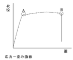
- FIG. 4 is an explanatory diagram of a stress curve obtained by a tensile test.
- FIG. 5 is a graph showing the results of the winding / unwinding test.
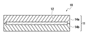
- the roll screen 10 has the solar cell element 12 as an essential component, and usually includes the solar cell module 11 having the sealing layer 14a, the solar cell element 12, and the sealing layer 14b as main components. That is, as 1st embodiment, as shown to FIG. 1A, the solar cell module 11 which has the sealing layer 14a, the solar cell element 12, and the sealing layer 14b as main components is mentioned.
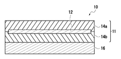
- the roll screen 10 may have a surface protective layer 13, a sealing material 15, and / or a back sheet 16.
- the back sheet 16 has at least one layer selected from a design layer and a weather resistant layer described later.
- a solar cell module 11 including a sealing layer 14a, a solar cell element 12, and a sealing layer 14b as main components, and a back sheet 16 is laminated.
- seat 16 is mentioned. Furthermore, as shown in FIG.
- the surface protection layer 13 the solar cell module 11 including the sealing layer 14a, the solar cell element 12, and the sealing layer 14b as main components
- seat 16 and the periphery of a solar cell module is sealed with the sealing material 15 is mentioned.
- the solar cell integrated roll screen of this invention can also take structures other than the said embodiment suitably.
- the roll screen 10 may include a reinforcing material.
- the roll screen 10 may have an ultraviolet cut layer, a gas barrier layer, and / or a getter material layer, and the ultraviolet cut layer, gas barrier layer, and / or getter material layer include the surface protective layer 13 and the sealing layer 14a. Even if it is the same as the sealing layer 14b and / or the back sheet 16, it may be separately provided at an arbitrary position.
- the size of the sealing layer 14a and the sealing layer 14b (hereinafter, these layers may be referred to as the sealing layer 14) is not limited as long as the solar cell element 12 can be sealed.
- the sizes of the surface protective layer 13 and the back sheet 16 are not particularly limited, but are usually preferably the same as the sealing layer 14 or larger than the sealing layer 14, and particularly from the viewpoint of manufacturing efficiency, the sealing layer 14 and Preferably they are the same.
- the back sheet 16 if the area
- the roll screen 10 has specific physical characteristics. When the roll screen is unwound, a force in the pulling direction is applied, and since the roll screen is extended from a bent state along the take-up pipe to a planar shape, stress in the bending direction is applied to both surfaces of the solar cell module. Further, when winding, a force in the pulling direction is applied, and since it is bent along the winding pipe from a flat state, stress in the bending direction is applied to both sides of the module.
- the solar cell element includes a brittle material such as a transparent electrode and has a complicated layer structure, so that stress generated when used as a roll screen is relieved in order to impart practical durability. There is a need to.
- the present invention by controlling the tensile strength of the roll screen and also the Young's modulus, the stress on the solar cell element is relaxed and the performance of the solar cell element is maintained.
- the tensile strength of the roll screen 10 of the present invention is 75 MPa or less. 60 MPa or less is preferable, 50 MPa or less is more preferable, 40 MPa or less is more preferable, and 35 MPa or less is most preferable. When the tensile strength of the roll screen 10 is equal to or less than the above upper limit, it is possible to suppress damage to the solar cell element due to bending stress and pulling that the solar cell module receives during unwinding.
- the tensile strength of the roll screen 10 is usually 5 MPa or more, preferably 10 MPa or more, more preferably 14 MPa or more, still more preferably 20 MPa or more, and most preferably 25 MPa or more.
- the tensile strength of the roll screen is equal to or higher than the above lower limit, the solar cell element is hardly damaged by suppressing the distortion inside the roll screen when the roll screen 10 is pulled with a certain force or more.
- the tensile strength of the roll screen 10 can be measured using a normal tensile tester, but is preferably measured by the method described later.
- the thickness and material are adjusted in a layer constituting the roll screen 10 described later.
- the layer that affects the tensile strength of the roll screen 10 include the surface protective layer 13 and the back sheet 16.
- a reinforcing material (a material having a high tensile strength) may be laminated on the roll screen 10 as necessary in order to make the strength of the roll screen 10 a certain level or more.
- the tensile strength can be controlled by arranging a material having a high tensile strength on the entire surface of the roll screen 10. When a material having a high tensile strength is laminated on the roll screen, it is preferable to make the layer adjacent to the material having a high tensile strength thick so that stress is not concentrated on some layers.
- the Young's modulus of the roll screen 10 of the present invention is usually 2000 MPa or less, preferably 1000 MPa or less, preferably 800 MPa or less, more preferably 650 MPa or less, and still more preferably 550 MPa or less.
- the entire roll screen is repelled by the stress in the opposite direction proportional to its Young's modulus against the bending stress generated when the roll screen is wound.
- the Young's modulus of the roll screen 10 is equal to or less than the above upper limit, the stress repelling against the strain at the time of unwinding does not become too large, so that the repulsive force hardly damages the solar cell element immediately after unwinding. If the Young's modulus of the roll screen 10 exceeds the upper limit, the roll screen may become too hard to be wound up.
- the lower limit is usually 50 MPa or more, preferably 100 MPa or more, more preferably 250 MPa or more, further preferably 300 MPa or more, particularly preferably 350 MPa or more, and most preferably 355 MPa or more.
- the Young's modulus of the roll screen 10 is equal to or more than the above lower limit, the stress generated during winding can be canceled and damage to the solar cell elements stacked inside can be suppressed.
- the Young's modulus of the roll screen 10 is lower than the lower limit value, the solar cell element is damaged, and the electric characteristics (particularly FF) of the solar cell such as leakage of the generated current are affected.
- the Young's modulus of the roll screen 10 can be measured using a normal tensile tester, but is preferably measured by the method described later.
- the Young's modulus of the roll screen 10 can be set to a desired value (preferably a value of 650 MPa or less) by appropriately adjusting the thickness and material of the layers constituting the roll screen 10.
- a desired value preferably a value of 650 MPa or less
- the layer that particularly affects the Young's modulus of the roll screen 10 include an inner layer close to the solar cell element, specifically, the sealing layer 14.
- the Young's modulus of the roll screen 10 can be increased by selecting a material having a high Young's modulus as the material for these layers. Then, the thickness of the above layer is adjusted so that the Young's modulus of the roll screen 10 does not become too high, or a material having a low Young's modulus is selected as the material, and the thickness of the adjacent layer is increased. Thus, the Young's modulus of the roll screen 10 can be adjusted. Specifically, the roll screen 10 has a desired Young's modulus by adjusting the thickness of each layer within a specific range in which the function of each layer is not impaired, preferably within the thickness range of each layer described later. be able to.
- the sealing layer should have a certain thickness or more. However, if the sealing layer is made too thick, deformation distortion due to bending during winding becomes large, which may have an adverse effect.
- the sealing layer also has the effect of maintaining the adhesiveness of the adjacent interface by releasing stress, so if the sealing layer is too thin, the above effect cannot be obtained, and adhesion failure such as peeling may occur during use There is.
- the Young's modulus of the roll screen 10 tends to be low, and it tends to be insufficient from the viewpoint of scratch resistance when the roll screen is wound.
- the surface protective layer is too thick, the Young's modulus of the roll screen 10 becomes too large, which may damage the solar cell element.
- the thickness of the entire roll screen is determined by the relationship of “surface protective layer ⁇ sealing layer”. The Young's modulus can be easily adjusted.
- a reinforcing material can be inserted to significantly increase the Young's modulus of the roll screen 10.
- the reinforcing material include nonwoven fabrics such as a glass nonwoven fabric and a polyester nonwoven fabric.
- the reinforcement may be adjacent to a material layer (eg, a sealing layer) having a relatively low Young's modulus in the roll screen or introduced into such a material layer.
- a material layer eg, a sealing layer
- Young's modulus of the entire roll screen can be easily controlled. In particular, it can be controlled by the thickness of the reinforcing material and the density per unit area.
- the density of the reinforcing material is too low, the effect of increasing the Young's modulus of the roll screen 10 by introducing the reinforcing material is low, and if the density of the reinforcing material is too high, it may be difficult to control the Young's modulus of the roll screen 10.
- the thickness of the roll screen is usually 0.2 mm or more, preferably 0.4 mm or more, more preferably 0.6 mm or more, and further preferably 0.8 mm or more. Moreover, it is 1.8 mm or less normally, Preferably it is 1.7 mm or less, More preferably, it is 1.6 mm or less, More preferably, it is 1.4 mm or less, Most preferably, it is 1.2 mm or less. If it is at least the above lower limit, it is difficult for the appearance change due to the winding / unwinding test to occur, and the stress applied when the roll screen 10 is wound is easily released, so that the solar cell element 12 is not easily damaged. If it is not more than the above upper limit, there is little distortion when the roll screen 10 is wound, so that the solar cell element 12 is not easily damaged.
- the size of the roll screen 10 is usually 50 ⁇ 60 (3000 cm 2 ) or more, preferably 70 ⁇ 100 (7000 cm 2 ), more preferably 80 ⁇ 120 (9600 cm 2 ), and most preferably 100 ⁇ 150 (15000 cm 2). ).
- the length of the roll screen 10 is usually 50 cm or more, preferably 70 cm or more, more preferably 80 cm or more, and most preferably 100 cm or more.
- the width of the roll screen 10 is usually 60 cm or more, preferably 100 cm or more, more preferably 120 cm or more, and most preferably 150 cm or more. It is preferable that the size, length, and width are equal to or more than the above lower limit, because the change in output as a solar cell is small even when the roll screen 10 has a local defect due to long-term use.
- the solar cell element 12 should just have a certain amount of flexibility (it is hard to be broken even if bending stress is repeatedly applied). Therefore, as the solar cell element 12, a so-called thin film solar cell element, specifically, an organic solar cell element, an amorphous silicon solar cell element, a compound semiconductor solar cell element, or the like can be preferably used.
- the solar cell element 12 usually has at least a transparent electrode, a photoelectric conversion layer, and a substrate, and when used as a solar cell integrated roll screen, the thickness of the transparent electrode and the base in the solar cell element is the sun. It is thought to affect the durability of the battery.
- the thickness of the transparent electrode is usually 200 ⁇ m or less, preferably 150 ⁇ m or less, more preferably 100 ⁇ m or less. It is considered that the effect of the present invention can be obtained when the thickness of the transparent electrode is at least the upper limit or less.
- a conductive metal oxide such as indium-tin oxide (ITO) or indium-zinc oxide (IZO) or a metal thin film is formed of a transparent oxide thin film such as a conductive metal oxide.
- ITO indium-tin oxide
- IZO indium-zinc oxide
- a metal thin film is formed of a transparent oxide thin film such as a conductive metal oxide.
- IMI sandwiched transparent conductive film
- the solar cell element 12 has a transparent electrode on the light receiving surface, and a layer of inorganic oxide or the like used as the transparent electrode is weak against compressive stress. Therefore, in order to prevent the transparent electrode from being deteriorated due to compressive stress, the roll screen 10 is wound around the take-up pipe 30 in a posture in which the light receiving surface side of the solar cell element 12 faces outward in a roll screen device (main body portion 100) described later. It is preferable to adopt a configuration that can be taken.
- the solar cell element 12 usually has a substrate.
- the thickness of the substrate of the solar cell element 12 is usually 100 ⁇ m or less, more preferably 50 ⁇ m or less, further preferably 25 ⁇ m or less, and most preferably 15 ⁇ m or less.
- the distortion generated by bending the solar cell-integrated roll screen can be alleviated by adjusting the thickness of the sealing layer.
- the sealing layer is too thick, the bending stress applied to the solar cell element is reversed. There is a risk of increasing.
- the thickness of the sealing material with respect to the substrate of the solar cell element is 2.3 or more.
- organic solar cell elements amorphous silicon solar cell elements, and compound semiconductor solar cell elements will be described as typical thin film solar cell elements.
- An organic solar cell element is a solar cell element using an organic semiconductor for a light absorption layer (photoelectric conversion layer).
- an organic solar cell element that is resistant to impacts such as fluttering is preferable because only a limited edge is fixed and installed.
- the organic solar cell element can be colored, if necessary, and is preferable from the viewpoint of design.
- the configuration is not particularly limited, for example, an electrode (anode), a buffer layer (hole extraction layer), a photoelectric conversion layer (organic active layer), a buffer layer (electron extraction layer), and an electrode (cathode) were sequentially formed. It has a layer structure and a substrate. You may have these layer structures on a board
- any one of an anode and a cathode should just be a transparent electrode which has translucency, and both may be translucent. Translucency means that sunlight passes through 40% or more.
- Two or more anodes or cathodes may be laminated, and characteristics (electric characteristics, wetting characteristics, etc.) may be improved by surface treatment.
- Anode material examples include conductive metal oxides such as indium-tin oxide (ITO) and indium-zinc oxide (IZO), metals such as silver, gold and aluminum, and metal thin films as conductive metals.
- ITO indium-tin oxide
- IZO indium-zinc oxide
- metals such as silver, gold and aluminum
- metal thin films as conductive metals.
- a transparent conductive film (IMI) having a three-layer structure sandwiched between transparent oxide thin films such as oxides, carbon materials such as carbon nanotubes and graphene, and conductive polymers doped with heteroatoms are used.
- the film thickness of the anode is not particularly limited, but is usually 10 nm or more, preferably 20 nm or more, and more preferably 50 nm or more. On the other hand, it is usually 10 ⁇ m or less, preferably 1 ⁇ m or less, more preferably 500 nm or less.
- the thickness of the anode is 10 nm or more, the sheet resistance is suppressed, and when the thickness of the anode is 10 ⁇ m or less, light can be efficiently converted into electricity without decreasing the light transmittance.
- the sheet resistance of the anode is not particularly limited, but is usually 1 ⁇ / ⁇ or more, on the other hand, 1000 ⁇ / ⁇ or less, preferably 500 ⁇ / ⁇ or less, more preferably 100 ⁇ / ⁇ or less.
- the cathode is a conductive material that generally has a higher work function than the anode.
- the cathode material examples include metals such as platinum, gold, silver, copper, iron, tin, zinc, aluminum, indium, chromium, lithium, sodium, potassium, cesium, calcium, and magnesium, and alloys thereof; lithium fluoride, Inorganic salts such as cesium fluoride; metal oxides such as nickel oxide, aluminum oxide, lithium oxide, or cesium oxide. These materials are preferred because they have a low work function.
- the anode material is preferably a metal such as platinum, gold, silver, copper, iron, tin, aluminum, calcium or indium, and an alloy using these metals.
- the film thickness of the cathode is not particularly limited, but is usually 10 nm or more, preferably 20 nm or more, and more preferably 50 nm or more. On the other hand, it is usually 10 ⁇ m or less, preferably 1 ⁇ m or less, more preferably 500 nm or less. When used for a transparent electrode, it is necessary to select a film thickness that achieves both light transmittance and sheet resistance. When the film thickness of the cathode is 10 nm or more, the sheet resistance is suppressed, and when the film thickness of the cathode is 10 ⁇ m or less, light can be efficiently converted into electricity without decreasing the light transmittance.
- the sheet resistance of the cathode is not particularly limited, but is usually 1000 ⁇ / ⁇ or less, preferably 500 ⁇ / ⁇ or less, and more preferably 100 ⁇ / ⁇ or less. Although there is no restriction on the lower limit, it is usually 1 ⁇ / ⁇ or more.
- the buffer layer can be classified into a hole extraction layer and an electron extraction layer, and can be provided between the organic active layer and the electrode, respectively. By providing the buffer layer, there are advantages that the mobility of electrons and holes between the organic active layer and the electrode is increased, and that a short circuit between the electrodes can be prevented.
- the hole extraction layer and the electron extraction layer are disposed so as to sandwich the organic active layer between a pair of electrodes.
- the organic solar cell element may have both a hole extraction layer and an electron extraction layer, or only one of them.
- the layer on the light-receiving surface side with respect to the organic active layer only needs to be translucent, and both may be translucent. Translucency means that sunlight passes through 40% or more.
- two or more hole extraction layers and electron extraction layers may be laminated, and characteristics (electric characteristics, wetting characteristics, etc.) may be improved by surface treatment.
- -Hole extraction layer Although the film thickness of a hole extraction layer is not specifically limited, Usually, they are 2 nm or more and 500 nm or less.
- -Electron taking-out layer Although the film thickness of an electron taking-out layer is not specifically limited, Usually, it is 0.1 nm or more and 500 nm or less.
- the material is not particularly limited, and specific examples include inorganic compounds and organic compounds.
- the inorganic compound include alkali metal salts such as LiF, and n-type oxide semiconductors such as titanium oxide (TiOx) and zinc oxide (ZnO).
- Organic compounds include phenanthrene derivatives such as bathocuproin (BCP) and bathophenanthrene (Bphen), and phosphine compounds having a double bond between a phosphorus atom and an oxygen atom or a double bond between a phosphorus atom and a sulfur atom in the molecule.
- an aromatic hydrocarbon group or an aromatic heterocyclic group phosphine compound may be used for the phosphorus atom, and among them, an aromatic hydrocarbon group or an aromatic heterocyclic group phosphine compound is preferable for the phosphorus atom.
- the organic active layer usually contains a p-type semiconductor compound and an n-type semiconductor compound.
- Examples of the layer structure of the organic active layer include a thin film stack type, a bulk heterojunction type, and a PIN type. Among these, a bulk heterojunction type in which a p-type semiconductor compound and an n-type semiconductor compound are mixed is preferable.
- the film thickness is not particularly limited, but is usually 10 nm or more and usually 10 ⁇ m or less.
- the method for forming the organic active layer is not particularly limited, but a coating method such as spin coating, die coating, gravure coating, dip coating, and ink jet is preferable.
- a p-type semiconductor compound is a material that operates as a p-type semiconductor whose film can transport holes, but a ⁇ -conjugated polymer material or a ⁇ -conjugated low-molecular organic compound is preferably used. A mixture of these compounds may also be used.
- the conjugated polymer material is obtained by polymerizing a single or a plurality of ⁇ -conjugated monomers, and the monomers include thiophene, fluorene, carbazole, diphenylthiophene, dithienothiophene, dithienosilole, dithieno which may have a substituent.
- Examples include cyclohexane, benzothiadiazole, thienothiophene, imidothiophene, benzodithiophene, and the molecular weight is preferably 10,000 or more. These monomers may be directly bonded, or may be bonded via an ethynyl group, an acetylinyl group, a nitrogen atom and / or an oxygen atom. Since the ⁇ -conjugated polymer material has durability against bending stress, it is preferable in terms of impact resistance and durability against opening and closing of the roll screen.
- Low molecular organic semiconductor materials include condensed aromatic hydrocarbons such as pentacene and naphthacene, oligothiophenes having four or more thiophene rings, porphyrin compounds such as porphyrin and tetrabenzoporphyrin compounds, and metal complexes thereof, and phthalocyanine compounds And metal complexes thereof.
- the HOMO level of the p-type semiconductor is usually ⁇ 5.7 eV or more and usually ⁇ 4.6 eV or less.
- the n-type semiconductor compound is not particularly limited, and examples thereof include fullerene compounds and derivatives thereof, and condensed ring tetracarboxylic acid diimides.
- fullerenes include C60 or C70, and those obtained by adding a substituent to two carbons of the fullerene, those having a substituent added to four carbons, and further adding a substituent to six carbons. Things.
- the fullerene compound is preferably highly soluble in some solvent and can be applied as a solution.
- the LUMO level of an n-type semiconductor is usually ⁇ 4.5 eV or more and usually ⁇ 2.0 eV or less.
- the material of the substrate is not particularly limited as long as it does not break even when bent as long as it is used as a solar cell integrated roll screen. Any material can be used as long as the effect as a solar cell is not significantly impaired.
- an inorganic material such as glass; polyethylene terephthalate, polyethylene naphthalate, polyethersulfone, polyimide, nylon, polystyrene, polyvinyl alcohol, ethylene vinyl alcohol copolymer, fluororesin film, vinyl chloride or Polyolefins such as polyethylene, cellulose, polyvinylidene chloride, aramid, polyphenylene sulfide, polyurethane, polycarbonate, polyarylate, polynorbornene, or epoxy resin; paper materials such as paper or synthetic paper; metals such as stainless steel, titanium, or aluminum
- a composite material such as a material whose surface is coated or laminated for imparting insulating properties can be used.
- the shape of the substrate there is no limitation on the shape of the substrate, and for example, a shape such as a film or a sheet can be used.
- substrate it is 5 micrometers or more normally, Preferably it is 20 micrometers or more, and is 100 micrometers or less normally, Preferably it is 50 micrometers or less. Since it is less likely that the strength of the organic solar cell element is insufficient, it is preferable to be at least the above lower limit. On the other hand, it is preferable that the amount is not more than the above upper limit because the cost is suppressed and the weight is not increased.
- Amorphous silicon solar cell element is a solar cell element using amorphous silicon for the photoelectric conversion layer.
- the amorphous silicon solar cell element has an advantage that it can sufficiently absorb sunlight even with a thin film having a thickness of about 1 ⁇ m.
- Amorphous silicon is an amorphous material that is highly resistant to bending. Therefore, when an amorphous silicon solar cell element is used as the solar cell element 12, a thin and lightweight roll screen 10 that is unlikely to cause destruction / performance deterioration of the solar cell element 12 due to winding on the winding pipe 30 is realized. can do.
- the configuration is not particularly limited, for example, it has a layer structure in which a photoelectric conversion layer is formed between two electrodes (anode and cathode) and a substrate. At least one of the electrodes is a transparent electrode.
- the transparent electrode include conductive metal oxides such as indium-tin oxide (ITO) and indium-zinc oxide (IZO), and metal thin films as conductive metal oxides.
- ITO indium-tin oxide
- IZO indium-zinc oxide
- a material similar to that of the organic solar cell such as a transparent conductive film (IMI) having a three-layer structure sandwiched between two transparent oxide thin films, can be used.
- IIMI transparent conductive film
- the same substrate as the organic solar cell element can be used.
- the photoelectric conversion layer preferably has a PIN structure.
- a compound semiconductor solar cell element is a solar cell using a compound semiconductor for a photoelectric conversion layer.
- a well-known thing can be used as a compound semiconductor type solar cell element.
- a structure is not specifically limited, For example, what has the structure laminated
- a buffer layer a well-known thing can be used as a buffer layer used for a compound semiconductor solar cell element, such as ZnO and CdS.
- At least one of the electrodes is a transparent electrode.
- a conductive metal oxide such as indium-tin oxide (ITO) or indium-zinc oxide (IZO), or a metal thin film is sandwiched between transparent oxide thin films such as conductive metal oxide 3
- ITO indium-tin oxide
- IZO indium-zinc oxide
- a metal thin film is sandwiched between transparent oxide thin films such as conductive metal oxide 3
- a transparent conductive film (IMI) having a layer structure can be used.
- the same substrate as the organic solar cell element can be used.
- I-III-VI group 2 semiconductor (chalcopyrite) solar cell elements that can obtain high photoelectric conversion efficiency are preferable, and Cu-III- using Cu as the group I element is particularly preferable.
- VI Group 2 semiconductor solar cell elements are preferred.
- the Cu-III-VI group 2 semiconductor solar cell element is a solar cell element having a Cu-III-VI group 2 semiconductor as a constituent material.
- the Cu-III-VI group 2 semiconductor is a semiconductor made of a compound containing Cu, a group III element, and a group VI element in a ratio of 1: 1: 2.
- Cu-III-VI group 2 semiconductor examples include CuInSe 2 , CuGaSe 2 , Cu (In 1-x Ga x ) Se 2 , CuInS 2 , CuGaS 2 , Cu (In 1-x Ga x ) S 2 , CuInTe 2.
- CuGaTe 2 and Cu (In 1-x Ga x ) Te 2 can be exemplified.
- the constituent material of the compound semiconductor solar cell element used as the solar cell element 12 may be a mixture of two or more of these.
- a compound semiconductor type solar cell element a CIS type solar cell element and a CIGS type solar cell element are particularly preferable.
- the CIS solar cell element is a solar cell element having a CIS semiconductor as a constituent material, and the CIS semiconductor is CuIn (Se 1-y S y ) 2 [0 ⁇ y ⁇ 1]. That is. That is, the CIS-based semiconductor is CuInSe 2 , CuInS 2 , or those in a mixed state.
- the CIGS solar cell element is a solar cell element having a CIGS semiconductor as a constituent material, and the CIGS semiconductor is Cu (In 1-x Ga x ) (Se 1-y S y ) 2. [0 ⁇ x ⁇ 1, 0 ⁇ y ⁇ 1].
- Cu (In 1-x Ga x ) Se 2 is usually a mixed crystal of CuInSe 2 and CuGaSe 2 .
- the range of x is usually greater than 0, preferably greater than 0.05, more preferably greater than 0.1, and usually less than 0.8, preferably less than 0.5, more preferably 0. Less than 4.
- the surface protective layer 13 is a layer for protecting the solar cell element 12 from weather changes and the like.
- the surface protective layer 13 is a layer for protecting the solar cell element 12 from weather changes and the like.
- Some of the constituent elements of the solar cell element 12 are deteriorated by temperature change, humidity change, natural light, erosion caused by wind and rain, and the like. Therefore, it is preferable to suppress the deterioration of the power generation capacity by covering the solar cell element 12 with the surface protective layer 13 to protect the solar cell element 12 and the like from weather changes and the like.
- the surface protective layer 13 is located on the outermost layer of the roll screen 10, the surface coating of the roll screen 10 (solar cell element 12) such as weather resistance, heat resistance, transparency, water repellency, stain resistance, mechanical strength, etc. It is preferable to have properties suitable for a material and to maintain it for a long period of time in outdoor exposure.
- the roll screen 10 is preferably one that can be wound compactly. Therefore, the surface protective layer 13 is preferably thin.
- the thickness of the surface protective layer 13 is usually 25 ⁇ m or more, preferably 50 ⁇ m or more, more preferably 70 ⁇ m or more. Moreover, it is 200 micrometers or less normally, Preferably it is 180 micrometers or less, More preferably, it is 150 micrometers or less, More preferably, it is 100 micrometers or less.
- the flexibility of the roll screen is increased and it is easy to wind up.
- weather resistance is easily secured, which is preferable.
- the surface protective layer 13 is preferably one that transmits visible light from the viewpoint of not preventing the solar cell element 12 from absorbing light.
- the visible light (wavelength 360 to 830 nm) light transmittance of the surface protective layer 13 is preferably 80% or more, more preferably 90% or more, and particularly preferably 95%.
- the surface protective layer 13 also has heat resistance.
- the melting point of the constituent material of the surface protective layer 13 is usually 100 ° C. or higher, preferably 120 ° C. or higher, more preferably 130 ° C. or higher, and usually 350 ° C. or lower, preferably 320 ° C. or lower, more preferably. Is 300 ° C. or lower.
- the material constituting the surface protective layer 13 is arbitrary as long as it can protect the solar cell element 12 from weather changes.
- the material include polyethylene resin, polypropylene resin, cyclic polyolefin resin, AS (acrylonitrile-styrene) resin, ABS (acrylonitrile-butadiene-styrene) resin, polyvinyl chloride resin, fluorine resin, polyethylene terephthalate, polyethylene
- polyester resins such as naphthalate, phenol resins, polyacrylic resins, polyamide resins such as various nylons, polyimide resins, polyamide-imide resins, polyurethane resins, cellulose resins, silicone resins, and polycarbonate resins.
- fluorine resin is preferable, and specific examples thereof include polytetrafluoroethylene (PTFE), 4-fluoroethylene-perchloroalkoxy copolymer (PFA), 4-fluoroethylene-6-fluoride.
- PTFE polytetrafluoroethylene
- PFA 4-fluoroethylene-perchloroalkoxy copolymer
- FEP Propylene copolymer
- ETFE 2-ethylene-4-fluoroethylene copolymer
- PCTFE poly-3-fluoroethylene chloride
- PVDF polyvinylidene fluoride
- PVF polyvinyl fluoride
- the surface protective layer 13 has functions such as ultraviolet ray blocking, heat ray blocking, antifouling property, antifogging property, abrasion resistance, conductivity, antireflection, antiglare property, light diffusion, light scattering, wavelength conversion, gas barrier property, etc. May be given.
- the surface protective layer 13 may have an ultraviolet blocking function.
- a layer having an ultraviolet blocking function is laminated on the surface protective layer by coating or the like, or a material that exhibits an ultraviolet blocking function is dissolved and dispersed in the surface protective layer so as to be contained in the surface protective layer. Can provide UV blocking function.
- the surface protective layer 13 may be formed of one kind of material or two or more kinds of materials.
- the surface protective layer 13 may be a single layer or a laminate of two or more layers.
- the surface protective layer 13 may be subjected to a surface treatment such as a corona treatment or a plasma treatment in order to improve adhesion with other layers.
- the surface protective layer 13 is preferably provided on the outer side of the roll screen 10 as much as possible. This is because more components of the roll screen 10 can be protected. Therefore, the surface protective layer 13 is preferably provided on the outermost surface of the roll screen 10.
- the surface of the back sheet 16 where the solar cell element 12 is not provided (inside the room) and the surface side of the surface protective layer 13 will be bonded together in the wound state.
- the surface of the layer 13 may be embossed. Further, the embossing of the surface of the roll screen 10 is effective for suppressing reflection of light from the roll screen 10 and making it unglare when viewed from the outside.
- sealing layer 14a and sealing layer 14b are layers that reinforce the solar cell element 12. Since the solar cell element 12 is thin, the strength is usually weak, and thus the strength of the roll screen 10 tends to be weak. However, the strength can be maintained high by the sealing layer 14.
- the sealing layer 14 is preferably thin. Usually, it is 120 ⁇ m or more, preferably 200 ⁇ m or more, more preferably 250 ⁇ m or more. Moreover, it is 500 micrometers or less normally, Preferably it is 450 micrometers or less, More preferably, it is 400 micrometers or less. By setting it to the upper limit or less, the flexibility of the roll screen 10 is increased and the roll screen 10 is easily wound. Moreover, it becomes easy to ensure the intensity
- the sealing layer 14 preferably has a high strength from the viewpoint of maintaining the strength of the roll screen 10.
- the specific strength is related to the strength of the surface protective layer 13 and the backsheet other than the sealing layer 14 and is difficult to define unconditionally, but the sealing layer 14 is used to wind the roll screen 10 described later. It is desirable to have adhesiveness and strength that do not cause peeling or deformation in each part of the roll screen 10 even if the pipe 30 is wound or stretched.
- the sealing layer 14a is preferably one that transmits visible light from the viewpoint of not preventing the solar cell element 12 from absorbing light.
- the visible light (wavelength 360 to 830 nm) transmittance of the sealing layer 14a is usually 60% or more, preferably 70% or more, more preferably 75% or more, still more preferably 80% or more, and most preferably 85% or more, particularly preferably 90% or more, particularly preferably 95% or more, and particularly preferably 97% or more, and usually 99% or less. It is preferable for it to be greater than or equal to the above lower limit because more sunlight is converted into electrical energy.
- the sealing layer 14b may be one that does not transmit visible light.
- the sealing layer 14a and the sealing layer 14b may be the same or different, but are preferably the same in terms of ease of manufacture.
- the sealing layer 14 preferably has heat resistance.
- the melting point of the constituent material of the sealing layer 14 is usually 100 ° C. or higher, preferably 120 ° C. or higher, more preferably 130 ° C. or higher. By increasing the melting point, it is possible to reduce the possibility that the sealing layer 14 is melted and deteriorated when the roll screen device is used.
- it is 350 degrees C or less normally, Preferably it is 320 degrees C or less, More preferably, it is 300 degrees C or less.
- Examples of the material constituting the sealing layer 14 include ethylene-vinyl acetate copolymer (EVA), ethylene-ethyl acrylate copolymer (EEA), ethylene-methyl acrylate copolymer (EMA), and ethylene.
- EVA ethylene-vinyl acetate copolymer
- EAA ethylene-ethyl acrylate copolymer
- EMA ethylene-methyl acrylate copolymer
- EMMA ethylene-Methyl methacrylate copolymer
- EMMA ethylene-methacrylic acid copolymer
- a fluoropolymer mainly composed of tetrafluoroethylene (TFE), hexafluoropropylene (HFP), vinylidene fluoride (VdF), tetrafluoroethylene (TFE), or vinylidene fluoride (VdF) is also exemplified.
- TFE tetrafluoroethylene
- HFP hexafluoropropylene
- VdF vinylidene fluoride
- TFE tetrafluoroethylene
- VdF vinylidene fluoride
- VdF vinylidene fluoride
- a crosslinkable sealing material is preferable.
- a non-crosslinkable sealing material is preferable in order to maintain flexibility.
- the surface protective layer 13 has the surface protective layer 13 Is preferred. That is, a solar cell integrated roll screen in which a surface protective layer, a sealing layer, and a solar cell element layer are sequentially laminated is preferable.
- the sealing layer 14 a for the surface protective layer 13 that is, the thickness of the surface protective layer 13 and the sealing layer positioned between the surface protective layer 13 and the solar cell element 12.
- the ratio is preferably 30 or less, more preferably 20 or less, and still more preferably 15 or less.
- the distortion with respect to the bending of the roll screen can be effectively relieved, so that it is possible to suppress the FF from decreasing even if the winding diameter is small.
- the smaller the winding diameter the better the effect. This is because if the ratio of the thickness of the sealing layer 14a to the surface protective layer is too large, the interface between the surface protective layer and the sealing layer is too biased toward the surface protective layer.
- the ratio of the thickness of the sealing layer 14a to the surface protective layer 13 is preferably 0.5 or more.
- the product of the ratio of the thickness of the sealing layer 14a to the surface protective layer 13 and the Young's modulus in the winding direction is preferably 610 or more, more preferably 640 or more, and even more preferably 1000. Above, most preferably 1500 or more.
- the backsheet 16 includes a design layer and / or a back surface protective layer.
- the backsheet 16 may be a single layer or two or more layers.
- the back sheet 16 is preferably laminated so as to have a back surface protective layer on the innermost surface on the indoor side.
- the backsheet 16 is usually 10 ⁇ m or more, preferably 15 ⁇ m or more, more preferably 20 ⁇ m or more, and usually 800 ⁇ m or less, preferably 500 ⁇ m or less, more preferably 300 ⁇ m or less. By making it below the upper limit, the flexibility tends to increase and winding becomes easy, and making it above the lower limit is preferable because it is easy to ensure weather resistance.
- a thicker sheet is preferable for ensuring weather resistance.
- the design layer is a layer that is located on the back surface of the roll screen 10 and imparts design properties to the indoor surface of the roll screen device.
- the design layer is thin.
- the thickness of the design layer is usually 10 ⁇ m or more, preferably 15 ⁇ m or more, more preferably 20 ⁇ m or more, and usually 800 ⁇ m or less, preferably 500 ⁇ m or less, more preferably 300 ⁇ m or less.
- the material of the design layer may be a natural material such as Japanese paper, cotton or hemp, in addition to those made from resin such as polypropylene or polyester. Also, a blend of synthetic fibers such as polyester and natural materials such as cotton and hemp may be used.
- the design layer may have a high light-shielding property or may have a low (so-called translucency). Further, the design layer may have a heat shielding property.
- the color of the design layer may be any color, but white, beige, brown, blue, green, etc. are preferably used from the viewpoint of design. Moreover, in order to improve designability, you may give a desired pattern especially indoor side. Further, in order to eliminate the possibility that the surface of the design layer on which the solar cell element 12 is not provided (inside the room) and the surface side of the surface protective layer 13 are bonded in the wound state. It is also possible to emboss the 16 indoor surfaces.
- the roll screen 10 preferably has a back surface protective layer as a back sheet.
- the back surface protective layer is preferably thin. It is usually 10 ⁇ m or more, preferably 15 ⁇ m or more, more preferably 20 ⁇ m or more, and is usually 200 ⁇ m or less, preferably 180 ⁇ m or less, more preferably 150 ⁇ m or less. Thinning tends to increase flexibility and facilitates winding, but too thin is not preferable because weather resistance is not ensured.
- the back surface protective layer is the same layer as the surface protective layer 13 described above, and the same material as the surface protective layer 13 can be used in the same manner except for the arrangement position. Moreover, since the constituent member on the back side of the solar cell element 12 does not necessarily need to transmit visible light, a member that does not transmit visible light can be used. Therefore, what is demonstrated below can also be used as a back surface protective layer.
- polyethylene resin polypropylene resin, cyclic polyolefin resin, polystyrene resin, acrylonitrile-styrene copolymer (AS resin), acrylonitrile-butadiene-styrene copolymer (ABS resin), polyvinyl chloride resin, fluorine Resins, poly (meth) acrylic resins, polycarbonate resins, polyester resins such as polyethylene terephthalate or polyethylene naphthalate, polyamide resins such as various nylons, polyimide resins, polyamideimide resins, polyarylphthalate resins , Silicone resin, polysulfone resin, polyphenylene sulfide resin, polyethersulfone resin, polyurethane resin, acetal resin, cellulose resin, and other various resin sheets It can be used.
- AS resin acrylonitrile-styrene copolymer
- ABS resin acrylonitrile-butadiene-styrene copolymer
- fluorine resin cyclic polyolefin resin, polycarbonate resin, poly (meth) acrylic resin, polyamide resin, or polyester resin.
- fluororesin include polytetrafluoroethylene (PTFE), 4-fluorinated ethylene-perchloroalkoxy copolymer (PFA), 4-fluorinated ethylene-6-fluorinated propylene copolymer (FEP). 2-ethylene-4-fluoroethylene copolymer (ETFE), poly-3-fluoroethylene chloride (PCTFE), polyvinylidene fluoride (PVDF), and polyvinyl fluoride (PVF).
- PTFE polytetrafluoroethylene
- PFA 4-fluorinated ethylene-perchloroalkoxy copolymer
- FEP 4-fluorinated ethylene-6-fluorinated propylene copolymer
- EFE 2-ethylene-4-fluoroethylene copolymer
- PCTFE poly-3-fluoroethylene chloride
- PVDF polyviny
- Seal material 15 In order to seal the edges of the surface protective layer 13, the sealing layers 14 a and 14 b, and the back sheet 16 described above, a sealing material may be used. As shown in FIG. 1D, a shape in which the sealing layers 14 a and 14 b and the sealing material 15 are sandwiched between the surface protective layer 13 and the back sheet 16 is preferable.
- the sealing material preferably has heat resistance.
- the melting point of the constituent material of the sealing material is usually 100 ° C. or higher, preferably 120 ° C. or higher, more preferably 130 ° C. or higher, and usually 250 ° C. or lower, preferably 200 ° C. or lower, more preferably 180 ° C. It is below °C. If the melting point is too low, the sealing material may melt when the roll screen 10 is used.
- the material constituting the sealing material examples include polymers such as fluorine resin, silicone resin, and acrylic resin. Note that the sealing material may be formed of one kind of material or two or more kinds of materials.
- the sealing material is provided at a position where each layer other than the surface protective layer 13 and the back sheet of the roll screen 10 can be sealed. Thereby, the space surrounded by the sealing material can be sealed, and moisture and oxygen can be prevented from entering the space.
- This sealing material can be formed by various methods. For example, it can be formed by injecting the constituent material of the sealing material between the surface protective layer 13 and the back sheet.
- the roll screen 10 is frequently rolled up or extended. Moreover, the roll screen 10 is easily heated by sunlight from the window. Under such conditions of use, the layers such as the sealing layer 14a tend to exhibit creep, warp or warp. In particular, since such deformation or the like is likely to occur in the edge portion of the roll screen 10, a reinforcing material may be provided in the roll screen 10.
- the reinforcing material is usually provided on the surface protective layer 13, the sealing layer 14a, the sealing layer 14b, and / or the back sheet 16.
- the sealing layer 14a, the sealing layer 14b, and / or the backsheet 16 Preferably included in the sealing layer 14a, the sealing layer 14b, and / or the backsheet 16, more preferably the sealing layer 14b (FIG. 1E), the backsheet 16 (FIG. 1F), or the sealing layer 14a and the back. It is included in the sheet 16 (FIG. 1G). Among them, it is preferably contained in the sealing layer 14 b or the back sheet 16, and most preferably contained in the back sheet 16. In addition, you may include the layer of a reinforcement material between the sealing layer 14b and the back seat
- the thickness of the reinforcing material is usually 30 ⁇ m or more, preferably 50 ⁇ m or more, and is usually 300 ⁇ m or less, preferably 250 ⁇ m or less. When the reinforcing material is mesh-shaped, the thickness of the reinforcing material is the maximum thickness of the mesh.
- the density per unit area of the reinforcing material is usually 0.5 mg / m 2 or more, preferably 1 mg / m 2 or more, more preferably 2 mg / m 2 or more, usually 50 mg / m 2 or less, preferably 30 mg / m. 2 or less, more preferably 20 mg / m 2 or less. If the density of the reinforcing material is too low, the effect of improving the Young's modulus is low, and if it is too high, control may be difficult.
- the reinforcing material examples include nonwoven fabrics or woven fabrics made of inorganic fibers such as glass and titanium, nonwoven fabrics or woven fabrics made of organic fibers such as polyamide, polyamideimide, polyimide, liquid crystalline polymer, and aromatic amide, and blends thereof.
- nonwoven fabrics or woven fabrics made of inorganic fibers such as glass and titanium
- nonwoven fabrics or woven fabrics made of organic fibers such as polyamide, polyamideimide, polyimide, liquid crystalline polymer, and aromatic amide, and blends thereof.
- a glass fiber nonwoven fabric is preferably used. Further, when this nonwoven fabric is used so as to be in contact with the sealing layers 14a and 14b, the surface of the glass fiber may be treated with a silane coupling agent in order to improve the adhesion between the sealing material resin and the glass fiber interface. good.
- silane coupling agents include vinyltrichlorosilane, vinyltriethoxysilane, vinyltrimethoxysilane, ⁇ -methacryloxypropyltrimethoxysilane, ⁇ -glycidoxypropylmethyldiethoxysilane, and ⁇ -aminopropyltriethoxy.
- Examples thereof include silane and ⁇ -chloropropyltrimethoxysilane.
- Treatment methods include a spray method in which an alcohol solution or an aqueous solution of a silane coupling agent is sprayed on the nonwoven fabric, a dipping method in which the nonwoven fabric is immersed in the solution, and a gravure coating method in which the nonwoven fabric is passed between rolls wet with the solution.
- the shape of the reinforcing material a shape that covers the entire group of solar cell elements 12 such as the sealing layers 14 a and 14 b or a shape that reinforces only the edge portion of the roll screen 10 can be employed.
- the solar cell integrated roll screen of the present invention may include a gas barrier layer, a getter material layer, and an ultraviolet absorbing layer. These layers can be laminated at any position according to the purpose. Hereinafter, each layer will be described.
- the gas barrier layer is a layer that prevents permeation of water and oxygen.
- the solar cell element 12 tends to be vulnerable to moisture and oxygen.
- transparent electrodes such as ZnO: Al, compound semiconductor solar cell elements, and organic solar cell elements may be deteriorated by moisture and oxygen. Therefore, it is preferable to protect the solar cell element 12 from water and oxygen by covering the solar cell element 12 with a gas barrier layer.
- the thickness of the gas barrier layer is not particularly limited, it is preferable that the roll screen 10 be wound in a compact manner, so that the gas barrier layer is preferably thin. It is usually 10 ⁇ m or more, preferably 15 ⁇ m or more, more preferably 20 ⁇ m or more, and is usually 200 ⁇ m or less, preferably 180 ⁇ m or less, more preferably 150 ⁇ m or less. By making it below the above upper limit, the flexibility tends to increase, and winding becomes easy. Since it becomes easy to ensure barrier property by setting it as the said minimum or more, it is preferable.
- the degree of moisture resistance required for the gas barrier layer varies depending on the type of solar cell element 12 and the like.
- the water vapor permeability per unit area (1 m 2 ) per day is 1 ⁇ 10 ⁇ 1 g / m 2 / day or less. Is preferably 1 ⁇ 10 ⁇ 2 g / m 2 / day or less, more preferably 1 ⁇ 10 ⁇ 3 g / m 2 / day or less, and further preferably 1 ⁇ 10 ⁇ 4 g / m 2.
- the water vapor permeability per unit area (1 m 2 ) is preferably 1 ⁇ 10 ⁇ 1 g / m 2 / day or less. It is more preferably 1 ⁇ 10 ⁇ 2 g / m 2 / day or less, further preferably 1 ⁇ 10 ⁇ 3 g / m 2 / day or less, and 1 ⁇ 10 ⁇ 4 g / m 2 / day.
- the following is particularly preferable, and it is particularly preferably 1 ⁇ 10 ⁇ 5 g / m 2 / day or less, and particularly preferably 1 ⁇ 10 ⁇ 6 g / m 2 / day or less.
- the water vapor transmission rate per unit area (1 m 2 ) per day is lower, deterioration due to the reaction between the solar cell element 12 and the transparent electrode such as ZnO: Al is suppressed, so that the power generation efficiency is increased and the lifetime is increased. Is extended.
- the degree of oxygen permeability required for the gas barrier layer varies depending on the type of solar cell element 12 and the like.
- the oxygen permeability per unit area (1 m 2 ) per day is 1 ⁇ 10 ⁇ 1 cc / m 2 / day / atm or less. It is preferably 1 ⁇ 10 ⁇ 2 cc / m 2 / day / atm or less, more preferably 1 ⁇ 10 ⁇ 3 cc / m 2 / day / atm or less, and further preferably 1 ⁇ 10 ⁇ 2 cc / m 2 / day / atm or less.
- the oxygen permeability per unit area (1 m 2 ) per day is 1 ⁇ 10 ⁇ 1 cc / m 2 / day / atm or less.
- ⁇ 4 cc / m 2 / day / atm or less is particularly preferable, and 1 ⁇ 10 ⁇ 5 cc / m 2 / day / atm or less is particularly preferable, and 1 ⁇ 10 ⁇ 6 cc / m 2 / day.
- Atm or less is particularly preferable.
- the deterioration of the solar cell element 12 and the transparent electrode such as ZnO: Al due to oxidation is suppressed as the oxygen does not permeate.
- the gas barrier layer is preferably one that transmits visible light from the viewpoint of not preventing the solar cell element 12 from absorbing light.
- the transmittance of visible light (wavelength 360 to 830 nm) is usually 60% or more, preferably 70% or more, more preferably 75% or more, still more preferably 80% or more, and particularly preferably 85% or more, especially It is preferably 90% or more, particularly preferably 95% or more, and particularly preferably 97% or more, and usually 99% or less. More sunlight can be converted into electric energy by being above the lower limit.
- the gas barrier layer preferably has resistance to heat.
- the melting point of the constituent material of the gas barrier layer is usually 100 ° C. or higher, preferably 120 ° C. or higher, more preferably 130 ° C. or higher, and usually 350 ° C. or lower, preferably 320 ° C. or lower, more preferably 300 It is below °C.
- the specific configuration of the gas barrier layer is arbitrary as long as the solar cell element 12 can be protected from water. However, since the manufacturing cost increases as the amount of water vapor or oxygen that can permeate the gas barrier layer decreases, it is preferable to use an appropriate material in consideration of these points comprehensively.
- Suitable gas barrier layers include, for example, a layer obtained by vacuum-depositing SiO x (value of x is 1.5 to 1.8) on a resin layer such as polyethylene terephthalate (PET) or polyethylene naphthalate (PEN). .
- AlO y (the value of y is 1.0 to 1.4) may be used instead of SiO x , and these two types of materials may be used.
- the resin layer constituting the gas barrier layer may be a single layer or a laminate of two or more layers.
- the getter material layer is a layer that absorbs moisture and / or oxygen. Some components of the solar cell element 12 are deteriorated by moisture as described above, and some are deteriorated by oxygen. Therefore, it is preferable to cover the solar cell element 12 with a getter material layer to protect the solar cell element 12 and the like from moisture and / or oxygen and to suppress a decrease in power generation capacity.
- the getter material layer absorbs moisture rather than impeding moisture permeation.
- the getter material layer captures moisture that slightly enters the space formed by the gas barrier layer and the sealing material, and the moisture The influence on the solar cell element 12 can be eliminated.
- the degree of water absorption capacity of the getter material layer is usually 0.1 mg / cm 2 or more, preferably 0.5 mg / cm 2 or more, more preferably 1 mg / cm 2 or more.
- it is usually 10 mg / cm ⁇ 2 > or less.
- the getter material layer absorbs oxygen
- the solar cell element 12 when the solar cell element 12 is covered with a gas barrier layer or the like, the getter material layer captures oxygen that slightly enters the space formed by the gas barrier layer and the seal material. Thus, the influence of oxygen on the solar cell element 12 can be eliminated.
- the thickness of the getter material layer is not particularly limited, but is usually 5 ⁇ m or more, preferably 10 ⁇ m or more, more preferably 15 ⁇ m or more, and usually 200 ⁇ m or less, preferably 180 ⁇ m or less, more preferably 150 ⁇ m or less.
- it is at least the above lower limit, it is easy to increase the water absorption capacity of the getter material layer, and when it is not more than the above upper limit, the flexibility of the roll screen 10 is increased and it tends to be easy to wind.
- the getter material layer is preferably one that transmits visible light from the viewpoint of not preventing the solar cell element 12 from absorbing light.
- the transmittance of visible light (wavelength 360 to 830 nm) is usually 60% or more, preferably 70% or more, more preferably 75% or more, still more preferably 80% or more, and particularly preferably 85% or more, especially Preferably it is 90% or more, Especially preferably, it is 95% or more, Especially preferably, it is 97% or more. This is to convert more sunlight into electrical energy.
- the getter material layer preferably has resistance to heat.
- the melting point of the constituent material of the getter material layer is usually 100 ° C. or higher, preferably 120 ° C. or higher, more preferably 130 ° C. or higher, and usually 350 ° C. or lower, preferably 320 ° C. or lower, more preferably It is 300 degrees C or less.
- the getter material layer includes a material that can absorb moisture and / or oxygen.
- the material include alkali metal, alkaline earth metal, alkaline earth metal oxide, alkali metal or alkaline earth metal hydroxide, silica gel, zeolite compound, magnesium sulfate as a substance that absorbs moisture. And sulfates such as sodium sulfate and nickel sulfate, and organometallic compounds such as aluminum metal complexes and aluminum oxide octylates.
- examples of the alkaline earth metal include Ca, Sr, and Ba.
- the alkaline earth metal oxide include CaO, SrO, and BaO.
- Other examples include Zr—Al—BaO and aluminum metal complexes.
- Specific product names include, for example, OleDry (manufactured by Futaba Electronics).
- substances that absorb oxygen include activated carbon, silica gel, activated alumina, molecular sieve, magnesium oxide, and iron oxide.
- activated carbon silica gel, activated alumina, molecular sieve, magnesium oxide, and iron oxide.
- Fe, Mn, Zn, and inorganic salts such as sulfates, chlorides, and nitrates of these metals are also included.
- the getter material layer only needs to contain a material that can absorb moisture and / or oxygen. Usually, it is a layer made of these materials or a resin layer containing these materials.
- the getter material layer may contain one or more of the above materials.
- the getter material layer may be a single layer or a laminate of two or more layers.
- the resin that disperses or dissolves the material that can absorb moisture and / or oxygen examples include, for example, polyethylene resins, polypropylene resins, cyclic polyolefin resins, polystyrene resins, and acrylonitrile-styrene copolymers (AS resins).
- AS resins acrylonitrile-styrene copolymers
- ABS resin Acrylonitrile-butadiene-styrene copolymer
- polyvinyl chloride resin polyvinyl chloride resin
- fluorine resin poly (meth) acrylic resin
- polycarbonate resin and the like
- the said resin may use 1 type and may use 2 or more types together by arbitrary combinations and a ratio.
- the ultraviolet cut layer is a layer that prevents the transmission of ultraviolet rays. Since some components of the roll screen 10 are deteriorated by ultraviolet rays, an ultraviolet cut layer may be used. For example, some types of gas barrier layers, which will be described later, are deteriorated by ultraviolet rays depending on the type. Therefore, by using an ultraviolet cut layer, it is possible to protect the gas barrier layer from ultraviolet rays and maintain its function high.
- the ultraviolet cut layer is thin.
- the thickness of the ultraviolet cut layer is usually 5 ⁇ m or more, preferably 10 ⁇ m or more, more preferably 15 ⁇ m or more, and is usually 200 ⁇ m or less, preferably 180 ⁇ m or less, more preferably 150 ⁇ m or less. Increasing the thickness tends to increase the absorption of ultraviolet rays, but if it is too thick, compactness cannot be secured.
- the degree of the ability to suppress the transmission of ultraviolet rays required for the ultraviolet cut layer is such that the transmittance of ultraviolet rays (for example, wavelength of 300 nm) is preferably 50% or less, more preferably 30% or less, and particularly preferably 10 % Or less.
- the UV cut layer is preferably one that transmits visible light from the viewpoint of not preventing the solar cell element 12 from absorbing light.
- the transmittance of visible light (wavelength 360 to 830 nm) is preferably 80% or more, more preferably 90% or more, and particularly preferably 95%.
- the ultraviolet cut layer also has heat resistance.
- the melting point of the constituent material of the ultraviolet cut layer is usually 100 ° C. or higher, preferably 120 ° C. or higher, more preferably 130 ° C. or higher, and usually 350 ° C. or lower, preferably 320 ° C. or lower, more preferably It is 300 degrees C or less. If the melting point is too low, the ultraviolet cut layer may be melted when the roll screen 10 is used.
- the UV cut layer is preferably one that has high flexibility, good adhesion to adjacent layers, and can cut water vapor and oxygen.
- the material constituting the ultraviolet cut layer is arbitrary as long as it can weaken the intensity of ultraviolet rays.
- Examples of the material include epoxy-based, acrylic-based, urethane-based and ester-based resins including an ultraviolet absorber.
- the ultraviolet absorber for example, a salicylic acid-based, benzophenone-based, benzotriazole-based, or cyanoacrylate-based one can be used. Of these, benzophenone and benzotriazole are preferable. Examples of this include various aromatic organic compounds such as benzophenone and benzotriazole.
- the ultraviolet absorber may be formed of one kind of compound or may be formed of two or more kinds of compounds.
- the ultraviolet cut layer may be a single layer or a laminate of two or more layers.
- the surface protective layer 13, the sealing layer 14a, and / or the sealing layer 14b may be provided with the function of an ultraviolet cut layer by containing the ultraviolet absorber, or may be provided at any other position.
- the ultraviolet cut layer is usually provided on the light receiving surface side of the solar cell element.
- each layer constituting the roll screen 10 is preferably a flame resistant material.
- a material obtained by adding a flame retardant to the sealing layers 14a and 14b can be used.
- the flame retardant is not particularly limited, and may be an inorganic flame retardant or an organic flame retardant.
- the inorganic flame retardant include metal oxides such as antimony compounds, bromine compounds, aluminum hydroxide, and magnesium hydroxide.
- Organic flame retardants include bromine compounds such as pentabromodiphenyl ether, octabromodiphenyl ether, tetrabromobisphenol A, hexabromodiclododecane, phosphorus compounds such as triphenyl phosphate, and chloride compounds such as red phosphorus and chlorinated paraffin. can give.
- bromine compounds such as pentabromodiphenyl ether, octabromodiphenyl ether, tetrabromobisphenol A, hexabromodiclododecane
- phosphorus compounds such as triphenyl phosphate
- chloride compounds such as red phosphorus and chlorinated paraffin.
- organic flame retardant material may damage the element, and bromine compounds such as pentabromodiphenyl ether, octabromodiphenyl ether, tetrabromobisphenol A, hexabromodichlorododecane, Phosphorus compounds such as phenyl phosphate are preferred.
- bromine compounds such as pentabromodiphenyl ether, octabromodiphenyl ether, tetrabromobisphenol A, hexabromodichlorododecane, Phosphorus compounds such as phenyl phosphate are preferred.
- an inorganic flame-retardant material is preferable from the viewpoint of safety during combustion.
- a filler such as a glass nonwoven fabric or silica can be added to a portion other than the solar cell element 12 of the roll screen 10. It is also possible to use a colored layer for the roll screen 10. The colored layer can be used between any layers in the roll screen 10. Since a colored material such as the solar cell element 12 can be changed to an arbitrary color by using a colored layer on the back sheet side from the surface protective layer 13, it is preferable from the viewpoint of design.
- the roll screen 10 can be manufactured by various methods.
- the surface protective layer 13, the sealing layer 14a, the solar cell element 12, the sealing layer 14b, and the film that is the material of the back sheet 16 are overlapped and integrated by a general laminating apparatus.
- the film which is the material of the surface protective layer 13, the sealing layer 14a, the solar cell element 12, and the sealing layer 14b is overlapped and integrated with a general laminating apparatus to obtain a laminate including solar cells
- the laminate The body and the back sheet 16 may be bonded together using an adhesive as necessary.
- the surface protective layer 13, the sealing layer 14a, the solar cell element 12, the sealing layer 14b, and / or the back sheet 16 may be formed of a reinforcing material, an ultraviolet cut layer, a gas barrier layer, a getter material layer, or the like. And can be laminated in advance.
- Lamination can be performed by a known method such as thermal lamination or lamination by pressure bonding. Thermal lamination is preferred from the viewpoint of characteristics as a roll screen.
- the heating temperature is usually 130 ° C. or higher, preferably 140 ° C. or higher, and is usually 180 ° C. or lower, preferably 170 ° C. or lower.
- the heating time is usually 10 minutes or longer, preferably 20 minutes or longer, usually 100 minutes or shorter, preferably 90 minutes or shorter.
- the pressure is usually 0.001 MPa or more, preferably 0.01 MPa or more, and usually 0.2 MPa or less, preferably 0.1 MPa or less. By setting the pressure within this range, sealing can be reliably performed, and the sealing layers 14a and 14b from the end portions can be prevented from protruding and film thickness reduction due to over-pressurization, thereby ensuring dimensional stability.
- the heat resistance of the solar cell element is low, lamination by pressure bonding is preferable.
- an adhesive may be used as necessary.
- the type of adhesive is not particularly limited as long as it is an adhesive that does not affect winding / unwinding, and it is arbitrarily selected from known adhesives such as acrylic resins, epoxy resins, and silicone resins. it can.
- heat and ultraviolet light may be applied during pressure bonding.
- the amount of the adhesive is preferably used in such an amount that the thickness of the adhesive in the solar cell integrated roll screen is 20 ⁇ m or less.
- a laminated body including a solar cell element is attached to the back sheet
- an adhesive is attached to the back sheet, and the surface protective layer, the sealing layer, the solar battery cell, and the substrate are laminated and pressure-bonded.
- the method of pressure bonding is preferably the same method as that for lamination by pressure bonding.
- the periphery of the roll screen is not transparent for that purpose.
- the roll screen 10 according to the present embodiment can be suitably used, for example, as the roll screen for the roll screen device shown in FIG. 2 or the roll screen for the roll screen device shown in FIG. 3A. Also, it has a power generation function equivalent to that of a conventional solar cell.
- FIG. 2 is an example of a roll screen device according to the present embodiment.
- the two output terminals 130 included in the roll screen device shown in FIG. 2 are terminals to which devices (such as lighting fixtures) that operate with a DC voltage are connected.
- Each output terminal 130 is connected to each output terminal of the storage battery 120 (and the charge / discharge controller 110).
- the charge / discharge controller 110 is a circuit that charges the storage battery 120 with power from the main body 100 (power generated by the solar cell element 12 in the roll screen 10).
- the main body 100 is a kind of pull-cord (spring type) roll screen device composed of a roll screen 10, a winding pipe 30 having one end of the roll screen 10 fixed to the outer peripheral surface, a holding unit 40, and the like.
- the holding unit 40 is a unit for holding the winding pipe 30 in a rotatable form, in which a plurality of members are combined.
- the holding portion 40 is in a posture in which the back sheet 16 of the roll screen 10 faces the indoor side, directly inside or outside the window frame or via another member. Fixed.
- the take-up pipe 30 is a pipe-like member for taking up the roll screen 10. Since the one where the outer diameter of the winding pipe 30 is smaller, the roll screen 10 can be wound compactly, the size of the holding portion 40 can be reduced. However, if the outer diameter of the take-up pipe 30 is too small, the solar cell element 12 is easily damaged when the roll screen 10 is taken up or unwound as a result of an increase in distortion in the roll screen 10 caused by the take-up. Become. Therefore, the take-up pipe 30 has an outer diameter of usually 20 mm or more, preferably 22 mm or more, more preferably 30 mm or more, particularly preferably 40 mm or more, further preferably 50 mm or more, and most preferably 70 mm or more. Adopted.
- the power generation efficiency is 90% or more, preferably 95% or more with respect to the initial power generation efficiency. Can be maintained. Furthermore, by setting the outer diameter to 70 mm or more, it is possible to maintain the power generation efficiency of 95% or more, preferably 98% or more with respect to the initial power generation efficiency in the winding / unwinding test described later.
- an outer diameter is usually 500 mm or less, preferably 400 mm or less, more preferably 300 mm or less, preferably 200 mm or less, more preferably 120 mm or less, and most preferably 100 mm or less.
- constituent material of the winding pipe 30 may be anything.
- examples of the constituent material of the winding pipe 30 include metals such as aluminum and SUS, and resins such as polyester, acrylic, methacryl, and hard vinyl chloride.
- an urging mechanism for urging the winding pipe 30 with a rotational force in the winding direction of the roll screen 10 is provided.
- a brake mechanism (not shown) is provided in the winding pipe 30 so that the winding speed of the roll screen 10 is always equal to or lower than a predetermined speed (so as not to be excessively high).
- the winding pipe 30 whose rotational force is biased by the biasing mechanism is in a state where only a part of the roll screen 10 is wound (a plurality of roll screens 10 having different pull-out amounts).
- a stop position control mechanism (not shown) is also provided for stopping in any of the above states.
- a rotary connector 35 (in this embodiment, a two-pole type) is also provided in the winding pipe 30.
- the two terminals on one side of the rotary connector 35 are connected to a cable 50 for supplying power to the charge / discharge controller 110, and the two terminals on the other side of the rotary connector 35 are output from the roll screen 10. It is connected to terminals 10p and 10m.
- the output terminals 10p and 10m of the roll screen 10 are terminals connected to the positive terminal and the negative terminal of the solar cell element 12, respectively.
- FIG. 3A is another example of the roll screen device according to the present embodiment.
- the perspective view of the main body 10 in FIG. 3A is the illustration of the solar cell element 12 and the like omitted, and the part that is not actually visible is also shown by the solid line.
- the two output terminals 130 included in the roll screen device shown in FIG. 3A are terminals to which devices (such as lighting fixtures) that operate with a DC voltage are connected. Each output terminal 130 is connected to each output terminal of the storage battery 120 (and the charge / discharge controller 110).
- the charge / discharge controller 110 is a circuit that charges the storage battery 120 with power from the main body 100 (power generated by the solar cell element 12 in the roll screen 10).
- the main body 100 is a so-called awning device (also called roll awning, retractable awning, etc.).
- the main body 100 includes a roll screen 10, a winding pipe 30 having one end of the roll screen 10 fixed to the outer peripheral surface thereof, a holding unit 40, and the like.
- the holding unit 40 is a unit for holding the winding pipe 30 in a rotatable form, in which a plurality of members are combined.
- the holding portion 40 is fixed to the outside of the window frame directly or through another member so that the back sheet 16 of the roll screen 10 faces the indoor side.
- the holding portion 40 includes a member 41 extending in the axial direction of the winding pipe 30, two arm portions 42, and an end of the roll screen 10 on the side not fixed to the winding pipe 30. And a member 45 to which is attached.
- Each arm portion 42 included in the holding portion 40 has a first arm 42a coupled to the member 41 via a joint member so as to be rotatable around one end thereof, and a joint member on the other end of the first arm 42a. And a second arm 42b coupled via a main component.
- a biasing member (such as a coil spring) for extending each arm portion 42 is attached to the joint member between the first arm 42 a and the second arm 42 b of each arm portion 42.
- each arm portion 42 that is not on the member 41 side is fixed to the member 45 via a joint member.
- the holding unit 40 is also provided with a mechanism (manual or electric mechanism) for rotating the winding pipe 30.
- maintenance part 40 is the shape so that the member 45 can be drawn near to the position shown to FIG. 3B (in other words, the roll screen 10 can be completely wound around the picking pipe 30 every period). It has been established.
- the take-up pipe 30 is a pipe-like member for taking up the roll screen 10. Since the one where the outer diameter of the winding pipe 30 is smaller, the roll screen 10 can be wound compactly, the size of the holding portion 40 can be reduced. However, if the outer diameter of the take-up pipe 30 is too small, the solar cell element 12 is easily damaged when the roll screen 10 is taken up or unwound as a result of an increase in distortion in the roll screen 10 caused by the take-up. Become. Therefore, the take-up pipe 30 has an outer diameter of usually 20 mm or more, preferably 22 mm or more, more preferably 30 mm or more, particularly preferably 40 mm or more, further preferably 50 mm or more, and most preferably 70 mm or more. Adopted.
- Increasing the outer diameter is preferable in that the initial power generation efficiency can be easily maintained.
- the roll screen 10 of the present invention by setting the outer diameter to 50 mm or more, it is possible to maintain a power generation efficiency of 90% or more with respect to the initial power generation efficiency in a winding / unwinding test described later. Furthermore, by setting the outer diameter to 70 mm or more, it is possible to maintain the power generation efficiency of 95% or more, preferably 98% or more with respect to the initial power generation efficiency in the winding / unwinding test described later.
- an outer diameter is usually 500 mm or less, preferably 400 mm or less, more preferably 300 mm or less, preferably 200 mm or less, more preferably 120 mm or less, and most preferably 100 mm or less.
- constituent material of the winding pipe 30 may be anything.
- examples of the constituent material of the winding pipe 30 include metals such as aluminum and SUS, and resins such as polyester, acrylic, methacryl, and hard vinyl chloride.
- a two-pole type rotary connector 35 (not shown) is provided in the same manner as the winding pipe 30 (FIG. 2).
- the two terminals on one side of the rotary connector 35 are connected to a cable 50 for supplying power to the charge / discharge controller 110, and the two terminals on the other side of the rotary connector 35 are output from the roll screen 10.
- Terminals 10p and 10m are connected.
- the solar cell integrated roll screen 10 of this invention can be used suitably also for well-known roll screen apparatuses other than the roll screen apparatus which has the said structure.
- the solar cell integrated roll screen winding / unwinding mechanism of the present invention can use a known structure as the roll screen winding / unwinding mechanism.
- a roll screen winding / unwinding method suitable for the roll screen 10 of the present invention for example, (i) a constant force in the winding direction is applied to the winding pipe by a spring or the like, whereby the roll screen is wound. A method of pulling out the roll screen by pulling the end of the roll screen is used.
- the roll screen always receives a force in the winding / unwinding direction. Since the solar cell integrated roll screen 10 of the present invention can suppress damage to the solar cell element not only against bending stress but also against force in the tensile direction, the winding / unwinding of (i) and (ii) above. It can be suitably used for a roll screen device having a method.
- the unwinding of the solar cell integrated roll screen may be either manual or mechanical.
- the roll screen device in which the unwinding speed of the roll screen is substantially constant is preferable because the deterioration of the solar cell included in the solar cell integrated roll screen 10 becomes uniform.
- the unwinding of the solar cell integrated roll screen may be either manual or mechanical.
- a method of unwinding by the own weight of the roll screen is preferable.
- a member having a predetermined weight for example, a rod-shaped member having a predetermined weight
- a tensile test was performed on the sample pieces of each roll screen using a tensile tester (STA-1225 manufactured by ORIENTEC) at a crosshead speed of 50 mm / min.
- FIG. 4 shows a general stress curve (stress-strain curve) obtained by the above tensile test.
- stress curve has a sudden rise in stress in the first region (up to point A)
- the slope was calculated as the “Young's modulus” of each roll screen.
- sample piece breaks immediately thereafter or after a gentle area (A point to B point).
- the maximum stress at this time was taken as the tensile strength of the corresponding roll screen.
- Example 1 A 100 ⁇ m-thick ETFE film (100 MW-DCS manufactured by Asahi Glass Co., Ltd.) as the outermost light-receiving surface, a 200 ⁇ m-thick EVA film (F806 manufactured by HANGZHOU FIRST) as the upper sealing material, and an amorphous silicon power generation layer as the solar cell element PEN film with a thickness of 50 ⁇ m, EVA film with a thickness of 200 ⁇ m (F806 made by HANGZHOU FIRST) as a lower sealing material, and an ETFE film with a thickness of 100 ⁇ m (100 MW-DCS made by Asahi Glass Co., Ltd.) as the outermost layer on the indoor side.
- ETFE film 100 ⁇ m-thick ETFE film (100 MW-DCS manufactured by Asahi Glass Co., Ltd.) as the outermost light-receiving surface
- a 200 ⁇ m-thick EVA film F806 manufactured by HANGZHOU FIRST
- Example 2 a roll screen was produced in the same manner as in Example 1 except that an ETFE film having a thickness of 200 ⁇ m was used as the outermost light-receiving surface layer and the indoor-side outermost layer.
- Example 3 A 50 ⁇ m-thick ETFE film (50 MW-DCS manufactured by Asahi Glass Co., Ltd.) as the outermost light-receiving surface, a 300 ⁇ m-thick EVA film (CHI Kasei FHCE) as the upper sealing material, and an amorphous silicon-based power generation layer as the solar cell element were laminated.
- 50 ⁇ m-thick ETFE film 50 MW-DCS manufactured by Asahi Glass Co., Ltd.
- a 300 ⁇ m-thick EVA film CHI Kasei FHCE
- an amorphous silicon-based power generation layer as the solar cell element were laminated.
- ETFE films Alignment 50MW-DCS
- Example 4 a roll screen was produced in the same manner as in Example 3 except that a glass cloth having a thickness of 170 ⁇ m (WLA90M100EV067N manufactured by Nittobo Co., Ltd.) was used as the reinforcing material.
- a glass cloth having a thickness of 170 ⁇ m WLA90M100EV067N manufactured by Nittobo Co., Ltd.
- Example 5 a roll screen was produced in the same manner as in Example 3 except that a 500 ⁇ m-thick roll screen cloth (manufactured by Tosoh) was used as the indoor-side outermost layer.
- Example 6 15 ⁇ m thick PET film (Mitsubishi Resin V300) as the light receiving surface outermost layer, 500 ⁇ m thick EVA film (CHI Kasei UFHCE) as the upper sealing material, and amorphous silicon power generation layer as the solar cell element A 50 ⁇ m PEN film, a 500 ⁇ m thick EVA film (UFHCE made by CI Kasei) as the lower sealing material, and a 15 ⁇ m thick PET film (Mitsubishi Resin V300) as the indoor outermost layer were stacked in this order.
- a roll laminator (size: 20 cm ⁇ 35 cm) was produced by using a vacuum laminator and heat laminating at 150 ° C. (vacuum degree 80 Pa, vacuum time 5 minutes, pressurization time 5 minutes, holding 10 minutes).
- Example 7 Thickness of 50 ⁇ m thick ETFE film (50MW-DCS manufactured by Asahi Glass Co., Ltd.) as the outermost light receiving surface, 100 ⁇ m thick EVA (EC-M0942) as the upper sealing material, and amorphous silicon power generation layer as the solar cell element A 50 ⁇ m PEN film, a 100 ⁇ m thick EVA (EC-M0942) as the lower sealing material, and a 50 ⁇ m thick ETFE film (50 MW-DCS manufactured by Asahi Glass Co., Ltd.) as the outermost indoor layer are stacked in this order.
- a vacuum laminator heat laminating at 150 ° C. (vacuum degree 80 Pa, vacuum time 5 minutes, pressurization time 5 minutes, holding 5 minutes) to produce a roll screen (size: 25 cm ⁇ 35 cm) according to Example 1 did.
- Example 8 EVA film with a thickness of 200 ⁇ m as the upper sealing material (F806 made by HANGZHOU FIRST), PEN film with a thickness of 50 ⁇ m laminated with an amorphous silicon-based power generation layer as the solar cell element, EVA film with a thickness of 200 ⁇ m as the lower sealing material (HANGZHOU After stacking in the order of FIRST F806), heat lamination (vacuum degree 80 Pa, vacuum time 5 minutes, pressurization time 5 minutes, holding 10 minutes) at 150 ° C. using an NPC vacuum laminator, Example A roll screen according to 8 (size: 25 cm ⁇ 35 cm) was produced.
- F806 made by HANGZHOU FIRST
- EVA film with a thickness of 200 ⁇ m as the lower sealing material HANGZHOU After stacking in the order of FIRST F806), heat lamination (vacuum degree 80 Pa, vacuum
- Tables 1 and 2 show the tensile strength, Young's modulus and thickness of the roll screen and the results of the winding / unwinding test in each example. Moreover, the result of having calculated the FF (fill factor) change rate after winding / unwinding with respect to the initial stage in each Example is shown in FIG. The evaluation in Table 1 was performed according to the following criteria.
- FF maintenance ratio at diameter 70 mm or more after winding / unwinding test at winding diameter 70 mm or more with respect to FF before winding / unwinding test (hereinafter also referred to as initial FF).
- the FF retention rate was determined, and was 99% or more: ⁇ , 95% or more and less than 99%: ⁇ , 90% or more and less than 95%: ⁇ , or less than 90%: ⁇ .
- -Initial maximum output The ratio of the maximum output before the winding / unwinding test in each example to the maximum output before the winding / unwinding test of Example 1 (hereinafter also referred to as the initial maximum output) is obtained.
- the evaluation in Table 2 was performed according to the following criteria.
- the FF maintenance ratio after the winding / unwinding test at a winding diameter of 22 mm with respect to the initial FF is 95% or more: ⁇ , 90% or more 95 Less than%: ⁇ , 80% or more and less than 90%: ⁇ , less than 80%: x.
- Table 1 shows that the roll screens of Examples 1 to 9 (that is, within the scope of the present invention) having a tensile strength in the winding direction of 75 MPa or less (that is, within the scope of the present invention) do not decrease the output when the winding diameter is 70 mm or more. Yes.
- Comparative Example 1 in which the tensile strength in the winding direction is 75 MPa or more, the output decreases even if the winding diameter is 70 mm or more. That is, it can be seen that the solar cell integrated roll screen of the present invention has high durability of the solar cell.
- a roll screen whose Young's modulus in the winding direction is 650 MPa or less (that is, within the preferred range of the present invention) by comparing Examples 1 to 6, 8, and 9 with Example 7 and Comparative Example 1.
- the initial maximum output is high.
- the solar cell-integrated roll screens of the present invention it is shown that when the Young's modulus is 650 MPa or less, it is possible to produce a roll screen that is strong against forces such as bending and pressure applied in the production process and has a stable solar cell output. ing.
- the thickness ratio of the sealing layer to the surface protective layer is 30 or less. It can be seen that the output change with a winding diameter of 22 mm is small. That is, it is shown that the thickness ratio of the sealing layer to the surface protective layer needs to be 30 or less in order to maintain the durability of the solar cell when the winding diameter is small.
- the sealing layer in “the thickness ratio of the sealing layer to the surface protective layer” is a sealing layer on the surface protective layer side with respect to the solar cell element.
- the product of the thickness ratio of the sealing layer to the surface protective layer and the Young's modulus of the solar cell-integrated roll screen is obtained by comparing Examples 1, 3 to 5 and 7 with Examples 2 and 9. It can be seen that the change in the output of the winding diameter 22 is even smaller when it is 610 or more. On the other hand, when Examples 1 to 6, 8, and 9 are compared with Example 7 and Comparative Example 1, if the thickness of the roll screen is 0.4 mm or more, the roll screen may not be wrinkled during winding. Recognize.
- Examples 1 to 5 and 7 to 9 in which the thickness ratio of the sealing layer to the surface protective layer is 30 or less have electrical characteristics (FF) as solar cells even when the winding diameter is reduced. Is maintained.
Landscapes
- Engineering & Computer Science (AREA)
- Architecture (AREA)
- Structural Engineering (AREA)
- Microelectronics & Electronic Packaging (AREA)
- General Physics & Mathematics (AREA)
- Computer Hardware Design (AREA)
- Physics & Mathematics (AREA)
- Power Engineering (AREA)
- Electromagnetism (AREA)
- Civil Engineering (AREA)
- Condensed Matter Physics & Semiconductors (AREA)
- Chemical & Material Sciences (AREA)
- Crystallography & Structural Chemistry (AREA)
- Photovoltaic Devices (AREA)
Abstract
L'invention concerne un écran à enrouleur à cellules solaires intégrées ayant une grande résistance à l'enroulement/au déroulement. Le matériau constituant et l'épaisseur de chaque section de l'écran à enrouleur à cellules solaires intégrées (10) sont déterminés de sorte que la résistance à la traction dans la direction d'enroulement soit inférieure ou égale à 75 MPa. Le matériau constituant et l'épaisseur de chaque section de l'écran à enrouleur à cellules solaires intégrées (10) sont aussi de préférence déterminés de sorte que le module de Young dans la direction d'enroulement soit inférieur ou égal à 650 MPa.
Priority Applications (4)
| Application Number | Priority Date | Filing Date | Title |
|---|---|---|---|
| EP11854399.0A EP2660876A4 (fr) | 2010-12-27 | 2011-12-27 | Écran à enrouleur à cellules solaires intégrées |
| JP2012551027A JPWO2012091068A1 (ja) | 2010-12-27 | 2011-12-27 | 太陽電池一体型ロールスクリーン |
| CN2011800628852A CN103299435A (zh) | 2010-12-27 | 2011-12-27 | 太阳能电池一体型卷帘 |
| US13/929,049 US20130284234A1 (en) | 2010-12-27 | 2013-06-27 | Solar-cell-integrated roll screen |
Applications Claiming Priority (4)
| Application Number | Priority Date | Filing Date | Title |
|---|---|---|---|
| JP2010-289910 | 2010-12-27 | ||
| JP2010289910 | 2010-12-27 | ||
| JP2011242865 | 2011-11-04 | ||
| JP2011-242865 | 2011-11-04 |
Related Child Applications (1)
| Application Number | Title | Priority Date | Filing Date |
|---|---|---|---|
| US13/929,049 Continuation US20130284234A1 (en) | 2010-12-27 | 2013-06-27 | Solar-cell-integrated roll screen |
Publications (1)
| Publication Number | Publication Date |
|---|---|
| WO2012091068A1 true WO2012091068A1 (fr) | 2012-07-05 |
Family
ID=46383156
Family Applications (1)
| Application Number | Title | Priority Date | Filing Date |
|---|---|---|---|
| PCT/JP2011/080340 WO2012091068A1 (fr) | 2010-12-27 | 2011-12-27 | Écran à enrouleur à cellules solaires intégrées |
Country Status (5)
| Country | Link |
|---|---|
| US (1) | US20130284234A1 (fr) |
| EP (1) | EP2660876A4 (fr) |
| JP (1) | JPWO2012091068A1 (fr) |
| CN (1) | CN103299435A (fr) |
| WO (1) | WO2012091068A1 (fr) |
Cited By (8)
| Publication number | Priority date | Publication date | Assignee | Title |
|---|---|---|---|---|
| JP2014239087A (ja) * | 2013-06-05 | 2014-12-18 | 三菱化学株式会社 | 有機薄膜太陽電池の設置方法 |
| WO2015021098A1 (fr) * | 2013-08-06 | 2015-02-12 | 3M Innovative Properties Company | Matériau d'encapsulation pour pile solaire et module |
| JP2015118980A (ja) * | 2013-12-17 | 2015-06-25 | 三菱樹脂株式会社 | 太陽電池モジュール |
| JP2015135914A (ja) * | 2014-01-17 | 2015-07-27 | 三菱化学株式会社 | 太陽電池モジュール一体型膜材 |
| JP2019009991A (ja) * | 2017-06-20 | 2019-01-17 | ベイジン アポロ ディン ロン ソーラー テクノロジー カンパニー リミテッド | 携帯型巻軸式太陽光発電装置及び巻軸式太陽光発電装置 |
| US10665741B2 (en) | 2015-06-04 | 2020-05-26 | Total Shade Inc. | Window insulating and power generation system |
| JP2021525001A (ja) * | 2018-05-22 | 2021-09-16 | コミッサリア ア レネルジー アトミーク エ オ ゼネルジ ザルタナテイヴ | ポリマーからなる前部層と複合材料からなる後部層を含む軽量かつフレキシブルな太陽電池モジュール |
| WO2023181457A1 (fr) * | 2022-03-24 | 2023-09-28 | 株式会社Lixil | Dispositif de store à rouleau |
Families Citing this family (25)
| Publication number | Priority date | Publication date | Assignee | Title |
|---|---|---|---|---|
| TWM435771U (en) * | 2012-04-27 | 2012-08-11 | Giga Solar Materials Corp | Card type solar charger |
| JP5977154B2 (ja) * | 2012-11-26 | 2016-08-24 | トーソー株式会社 | 太陽電池付きロールスクリーン |
| US11362619B2 (en) * | 2015-05-28 | 2022-06-14 | Zeon Corporation | Photoelectric conversion device |
| CN106301155A (zh) * | 2015-06-05 | 2017-01-04 | 周起兴 | 便携式太阳能发电的电源装置 |
| WO2017052482A1 (fr) * | 2015-09-22 | 2017-03-30 | Yalcin Ahmet Fuat | Nouveaux rideau et pare-soleil permettant la production d'énergie |
| CN105545195B (zh) * | 2016-01-29 | 2017-05-31 | 华南理工大学 | 一种太阳能智能驱动的efte张拉膜外遮阳装置 |
| AU2017246326B2 (en) * | 2016-04-04 | 2022-05-26 | Savant Systems, Inc. | Combined window shade and solar panel |
| FR3052595B1 (fr) * | 2016-06-10 | 2018-07-13 | Commissariat A L'energie Atomique Et Aux Energies Alternatives | Procede de fabrication d'un module photovoltaique |
| CN106374826B (zh) * | 2016-10-09 | 2019-02-01 | 全普光电科技(上海)有限公司 | 智能保护器、太阳能电池及制备方法 |
| KR101824523B1 (ko) * | 2017-01-11 | 2018-02-01 | 엘지전자 주식회사 | 태양 전지 모듈 및 이를 구비하는 휴대용 충전기 |
| CN108400747A (zh) * | 2017-02-07 | 2018-08-14 | 李桢育 | 风力及太阳能电源储能系统 |
| US10273747B2 (en) * | 2017-04-07 | 2019-04-30 | Hall Labs Llc | Window covering with hybrid shade-battery |
| US20200204106A1 (en) * | 2017-06-19 | 2020-06-25 | Bolymedia Holdings Co. Ltd. | Reflective solar apparatus |
| EP3419140A1 (fr) * | 2017-06-20 | 2018-12-26 | Beijing Apollo Ding Rong Solar Technology Co., Ltd. | Dispositif de génération d'énergie solaire portable de type à rouleaux et dispositif de génération d'énergie solaire de type à rouleaux |
| IT201700090501A1 (it) * | 2017-08-04 | 2019-02-04 | Teleco Automation Srl | Dispositivo di controllo delle luci di una tenda avvolgibile motorizzata |
| KR102314575B1 (ko) * | 2018-01-12 | 2021-10-20 | 주식회사 엘지에너지솔루션 | 이차전지의 충방전기 및 이를 포함하는 이차전지의 활성화 공정 장치 |
| US10560050B2 (en) * | 2018-06-15 | 2020-02-11 | Evolusun, Inc. | Innovative energy generating photovoltaic awning |
| US11060349B2 (en) | 2018-07-13 | 2021-07-13 | Geigtech East Bay Llc | Window shade assembly |
| EP3982422A4 (fr) * | 2019-06-05 | 2022-07-27 | Panasonic Intellectual Property Management Co., Ltd. | Module de cellules solaires |
| US11784267B2 (en) * | 2019-10-29 | 2023-10-10 | Sun Hunter Inc. | CIGS lamination structure and portable solar charger using same |
| EP3964683A1 (fr) * | 2020-09-03 | 2022-03-09 | Solar BB Ltd | Volet solaire |
| CN112901053A (zh) * | 2021-04-07 | 2021-06-04 | 清华大学 | 遮阳发电的一体化幕墙结构 |
| US11226089B1 (en) * | 2021-04-12 | 2022-01-18 | National Christmas Products Llc | Illuminated shade or screen assembly |
| ES2933626A1 (es) * | 2021-05-19 | 2023-02-10 | Janez Garcia Javier | Toldo fotovoltaico flexible |
| DE102022108483A1 (de) * | 2022-04-07 | 2023-10-12 | Schott Ag | Vorderseitensubstrat für ein Solarmodul |
Citations (8)
| Publication number | Priority date | Publication date | Assignee | Title |
|---|---|---|---|---|
| JPH01201969A (ja) * | 1988-02-08 | 1989-08-14 | Teijin Ltd | 太陽電池電源ユニット |
| JPH03143588A (ja) | 1989-10-27 | 1991-06-19 | Shoei Pack:Kk | 浄水装置 |
| JP2000243989A (ja) | 1999-02-18 | 2000-09-08 | Dainippon Printing Co Ltd | 透明フィルム型太陽電池モジュール |
| JP2004127955A (ja) * | 2002-09-30 | 2004-04-22 | Fuji Electric Holdings Co Ltd | 太陽電池モジュール |
| JP2005136242A (ja) * | 2003-10-31 | 2005-05-26 | Fuji Electric Holdings Co Ltd | 太陽電池モジュールおよびその製造方法 |
| JP2008042142A (ja) | 2006-08-10 | 2008-02-21 | Ntt Facilities Inc | ロールカーテン装置 |
| JP2010177497A (ja) | 2009-01-30 | 2010-08-12 | Konica Minolta Holdings Inc | 太陽電池モジュール及び太陽光発電装置 |
| JP2010238863A (ja) * | 2009-03-31 | 2010-10-21 | Fujifilm Corp | 可撓性太陽電池モジュール |
Family Cites Families (15)
| Publication number | Priority date | Publication date | Assignee | Title |
|---|---|---|---|---|
| JPH01110777A (ja) * | 1987-10-23 | 1989-04-27 | Mitsubishi Electric Corp | 光発電装置 |
| JPH02175878A (ja) * | 1988-12-28 | 1990-07-09 | Canon Inc | 改良されたマイクロ波導入窓を有するマイクロ波プラズマcvd装置 |
| US5793174A (en) * | 1996-09-06 | 1998-08-11 | Hunter Douglas Inc. | Electrically powered window covering assembly |
| WO2004077576A1 (fr) * | 2003-02-25 | 2004-09-10 | Vhf Technologies Sa | Dispositif photovoltaique |
| US7281561B2 (en) * | 2004-06-07 | 2007-10-16 | Donald Anderson | Multi-layered film window system |
| KR20070104582A (ko) * | 2005-01-04 | 2007-10-26 | 쟈끄 람베이 | 광 발전 블라인드 또는 차양 |
| US7617857B2 (en) * | 2006-02-02 | 2009-11-17 | Brad Froese | Illuminated window blind assembly |
| CN201071671Y (zh) * | 2007-05-18 | 2008-06-11 | 张宇威 | 柔性太阳能电池窗帘 |
| CN201218042Y (zh) * | 2008-06-12 | 2009-04-08 | 格桑尼玛 | 多功能太阳能自动卷帘防盗窗 |
| FR2935540B1 (fr) * | 2008-08-29 | 2011-03-04 | Dickson Constant | Composite enroulable photovoltaique et dispositf de protection solaire comportant un tel composite |
| CN101418669B (zh) * | 2008-12-10 | 2011-05-18 | 吴速 | 太阳能一体化卷帘门窗 |
| SG173542A1 (en) * | 2009-02-09 | 2011-09-29 | Hunter Douglas Ind Bv | Spring system for roller blinds |
| WO2011014777A1 (fr) * | 2009-07-31 | 2011-02-03 | E. I. Du Pont De Nemours And Company | Agents dencapsulation réticulables pour cellules photovoltaïques |
| JP2011121320A (ja) * | 2009-12-11 | 2011-06-23 | Nippon Electric Glass Co Ltd | ガラスフィルム積層体、該積層体のガラスロール、及びガラスロールの製造方法 |
| US20130209816A1 (en) * | 2010-05-20 | 2013-08-15 | Toray Advanced Film Co., Ltd. | Backside protective sheet for solar cell module |
-
2011
- 2011-12-27 EP EP11854399.0A patent/EP2660876A4/fr not_active Withdrawn
- 2011-12-27 WO PCT/JP2011/080340 patent/WO2012091068A1/fr active Application Filing
- 2011-12-27 CN CN2011800628852A patent/CN103299435A/zh active Pending
- 2011-12-27 JP JP2012551027A patent/JPWO2012091068A1/ja active Pending
-
2013
- 2013-06-27 US US13/929,049 patent/US20130284234A1/en not_active Abandoned
Patent Citations (8)
| Publication number | Priority date | Publication date | Assignee | Title |
|---|---|---|---|---|
| JPH01201969A (ja) * | 1988-02-08 | 1989-08-14 | Teijin Ltd | 太陽電池電源ユニット |
| JPH03143588A (ja) | 1989-10-27 | 1991-06-19 | Shoei Pack:Kk | 浄水装置 |
| JP2000243989A (ja) | 1999-02-18 | 2000-09-08 | Dainippon Printing Co Ltd | 透明フィルム型太陽電池モジュール |
| JP2004127955A (ja) * | 2002-09-30 | 2004-04-22 | Fuji Electric Holdings Co Ltd | 太陽電池モジュール |
| JP2005136242A (ja) * | 2003-10-31 | 2005-05-26 | Fuji Electric Holdings Co Ltd | 太陽電池モジュールおよびその製造方法 |
| JP2008042142A (ja) | 2006-08-10 | 2008-02-21 | Ntt Facilities Inc | ロールカーテン装置 |
| JP2010177497A (ja) | 2009-01-30 | 2010-08-12 | Konica Minolta Holdings Inc | 太陽電池モジュール及び太陽光発電装置 |
| JP2010238863A (ja) * | 2009-03-31 | 2010-10-21 | Fujifilm Corp | 可撓性太陽電池モジュール |
Non-Patent Citations (1)
| Title |
|---|
| See also references of EP2660876A4 * |
Cited By (9)
| Publication number | Priority date | Publication date | Assignee | Title |
|---|---|---|---|---|
| JP2014239087A (ja) * | 2013-06-05 | 2014-12-18 | 三菱化学株式会社 | 有機薄膜太陽電池の設置方法 |
| WO2015021098A1 (fr) * | 2013-08-06 | 2015-02-12 | 3M Innovative Properties Company | Matériau d'encapsulation pour pile solaire et module |
| JP2015118980A (ja) * | 2013-12-17 | 2015-06-25 | 三菱樹脂株式会社 | 太陽電池モジュール |
| JP2015135914A (ja) * | 2014-01-17 | 2015-07-27 | 三菱化学株式会社 | 太陽電池モジュール一体型膜材 |
| US10665741B2 (en) | 2015-06-04 | 2020-05-26 | Total Shade Inc. | Window insulating and power generation system |
| JP2019009991A (ja) * | 2017-06-20 | 2019-01-17 | ベイジン アポロ ディン ロン ソーラー テクノロジー カンパニー リミテッド | 携帯型巻軸式太陽光発電装置及び巻軸式太陽光発電装置 |
| JP2021525001A (ja) * | 2018-05-22 | 2021-09-16 | コミッサリア ア レネルジー アトミーク エ オ ゼネルジ ザルタナテイヴ | ポリマーからなる前部層と複合材料からなる後部層を含む軽量かつフレキシブルな太陽電池モジュール |
| JP7408573B2 (ja) | 2018-05-22 | 2024-01-05 | コミッサリア ア レネルジー アトミーク エ オ ゼネルジ ザルタナテイヴ | ポリマーからなる前部層と複合材料からなる後部層を含む軽量かつフレキシブルな太陽電池モジュール |
| WO2023181457A1 (fr) * | 2022-03-24 | 2023-09-28 | 株式会社Lixil | Dispositif de store à rouleau |
Also Published As
| Publication number | Publication date |
|---|---|
| EP2660876A4 (fr) | 2017-05-17 |
| CN103299435A (zh) | 2013-09-11 |
| JPWO2012091068A1 (ja) | 2014-06-05 |
| US20130284234A1 (en) | 2013-10-31 |
| EP2660876A1 (fr) | 2013-11-06 |
Similar Documents
| Publication | Publication Date | Title |
|---|---|---|
| WO2012091068A1 (fr) | Écran à enrouleur à cellules solaires intégrées | |
| WO2011158777A1 (fr) | Module de cellule solaire | |
| JP2014179536A (ja) | ロールスクリーン及びロールスクリーン装置 | |
| US20180019423A1 (en) | Organic thin film solar cell module | |
| JP6094572B2 (ja) | 有機薄膜太陽電池モジュールの製造方法、及び有機薄膜太陽電池モジュール | |
| US20120305080A1 (en) | Solar cell module and method of manufacturing solar cell module | |
| JP2010021502A (ja) | ブラインド用太陽電池パネル及び縦型ブラインド | |
| JP2010021501A (ja) | ブラインド用太陽電池パネル及びブラインド | |
| JP2011254073A (ja) | ロールスクリーンシステム | |
| JP2014095233A (ja) | 縦型ブラインド | |
| JP2016186156A (ja) | 太陽電池一体型壁材 | |
| JP2014207321A (ja) | 有機薄膜太陽電池素子 | |
| WO2014003187A1 (fr) | Module de cellules solaires à couche mince organique | |
| JP2012080060A (ja) | 有機太陽電池モジュール | |
| JP2015194072A (ja) | 薄膜太陽電池モジュール | |
| JP2010049998A (ja) | コンセント及び電源供給切替装置 | |
| JP2016058606A (ja) | 太陽電池モジュール | |
| JP2013076281A (ja) | ロールスクリーン装置 | |
| JP2011254072A (ja) | 太陽電池装置 | |
| JP2016187010A (ja) | 薄膜太陽電池モジュール | |
| JP2015154049A (ja) | 薄膜太陽電池モジュール | |
| JP2013076293A (ja) | ロールスクリーン装置 | |
| JP5621657B2 (ja) | 太陽電池モジュール | |
| JP6458591B2 (ja) | 太陽電池装置 | |
| JP2017069395A (ja) | 有機薄膜太陽電池モジュール |
Legal Events
| Date | Code | Title | Description |
|---|---|---|---|
| 121 | Ep: the epo has been informed by wipo that ep was designated in this application |
Ref document number: 11854399 Country of ref document: EP Kind code of ref document: A1 |
|
| ENP | Entry into the national phase |
Ref document number: 2012551027 Country of ref document: JP Kind code of ref document: A |
|
| NENP | Non-entry into the national phase |
Ref country code: DE |
|
| WWE | Wipo information: entry into national phase |
Ref document number: 2011854399 Country of ref document: EP |