WO2012090841A1 - 極異方性配向を有する円弧状磁石、その製造方法、及びそれを製造するための金型 - Google Patents
極異方性配向を有する円弧状磁石、その製造方法、及びそれを製造するための金型 Download PDFInfo
- Publication number
- WO2012090841A1 WO2012090841A1 PCT/JP2011/079737 JP2011079737W WO2012090841A1 WO 2012090841 A1 WO2012090841 A1 WO 2012090841A1 JP 2011079737 W JP2011079737 W JP 2011079737W WO 2012090841 A1 WO2012090841 A1 WO 2012090841A1
- Authority
- WO
- WIPO (PCT)
- Prior art keywords
- cavity
- magnetic field
- arc
- central
- pair
- Prior art date
- Legal status (The legal status is an assumption and is not a legal conclusion. Google has not performed a legal analysis and makes no representation as to the accuracy of the status listed.)
- Ceased
Links
Images








Classifications
-
- H—ELECTRICITY
- H01—ELECTRIC ELEMENTS
- H01F—MAGNETS; INDUCTANCES; TRANSFORMERS; SELECTION OF MATERIALS FOR THEIR MAGNETIC PROPERTIES
- H01F7/00—Magnets
- H01F7/02—Permanent magnets [PM]
-
- B—PERFORMING OPERATIONS; TRANSPORTING
- B30—PRESSES
- B30B—PRESSES IN GENERAL
- B30B11/00—Presses specially adapted for forming shaped articles from material in particulate or plastic state, e.g. briquetting presses, tabletting presses
- B30B11/02—Presses specially adapted for forming shaped articles from material in particulate or plastic state, e.g. briquetting presses, tabletting presses using a ram exerting pressure on the material in a moulding space
- B30B11/027—Particular press methods or systems
-
- H—ELECTRICITY
- H01—ELECTRIC ELEMENTS
- H01F—MAGNETS; INDUCTANCES; TRANSFORMERS; SELECTION OF MATERIALS FOR THEIR MAGNETIC PROPERTIES
- H01F41/00—Apparatus or processes specially adapted for manufacturing or assembling magnets, inductances or transformers; Apparatus or processes specially adapted for manufacturing materials characterised by their magnetic properties
- H01F41/02—Apparatus or processes specially adapted for manufacturing or assembling magnets, inductances or transformers; Apparatus or processes specially adapted for manufacturing materials characterised by their magnetic properties for manufacturing cores, coils, or magnets
- H01F41/0253—Apparatus or processes specially adapted for manufacturing or assembling magnets, inductances or transformers; Apparatus or processes specially adapted for manufacturing materials characterised by their magnetic properties for manufacturing cores, coils, or magnets for manufacturing permanent magnets
- H01F41/0273—Imparting anisotropy
-
- B—PERFORMING OPERATIONS; TRANSPORTING
- B22—CASTING; POWDER METALLURGY
- B22F—WORKING METALLIC POWDER; MANUFACTURE OF ARTICLES FROM METALLIC POWDER; MAKING METALLIC POWDER; APPARATUS OR DEVICES SPECIALLY ADAPTED FOR METALLIC POWDER
- B22F2998/00—Supplementary information concerning processes or compositions relating to powder metallurgy
- B22F2998/10—Processes characterised by the sequence of their steps
-
- B—PERFORMING OPERATIONS; TRANSPORTING
- B22—CASTING; POWDER METALLURGY
- B22F—WORKING METALLIC POWDER; MANUFACTURE OF ARTICLES FROM METALLIC POWDER; MAKING METALLIC POWDER; APPARATUS OR DEVICES SPECIALLY ADAPTED FOR METALLIC POWDER
- B22F2999/00—Aspects linked to processes or compositions used in powder metallurgy
-
- B—PERFORMING OPERATIONS; TRANSPORTING
- B22—CASTING; POWDER METALLURGY
- B22F—WORKING METALLIC POWDER; MANUFACTURE OF ARTICLES FROM METALLIC POWDER; MAKING METALLIC POWDER; APPARATUS OR DEVICES SPECIALLY ADAPTED FOR METALLIC POWDER
- B22F3/00—Manufacture of workpieces or articles from metallic powder characterised by the manner of compacting or sintering; Apparatus specially adapted therefor ; Presses and furnaces
- B22F3/02—Compacting only
-
- B—PERFORMING OPERATIONS; TRANSPORTING
- B22—CASTING; POWDER METALLURGY
- B22F—WORKING METALLIC POWDER; MANUFACTURE OF ARTICLES FROM METALLIC POWDER; MAKING METALLIC POWDER; APPARATUS OR DEVICES SPECIALLY ADAPTED FOR METALLIC POWDER
- B22F3/00—Manufacture of workpieces or articles from metallic powder characterised by the manner of compacting or sintering; Apparatus specially adapted therefor ; Presses and furnaces
- B22F3/02—Compacting only
- B22F3/03—Press-moulding apparatus therefor
-
- C—CHEMISTRY; METALLURGY
- C22—METALLURGY; FERROUS OR NON-FERROUS ALLOYS; TREATMENT OF ALLOYS OR NON-FERROUS METALS
- C22C—ALLOYS
- C22C2202/00—Physical properties
- C22C2202/02—Magnetic
Definitions
- the present invention relates to an arc-shaped magnet having polar anisotropic orientation, a method for manufacturing the same, and a mold for manufacturing the same.
- Permanent magnets consisting essentially of R-TM-B are widely used because they are inexpensive and have high magnetic properties.
- R-TM-B materials have high mechanical strength and low brittleness, so even if large internal stress is generated due to shrinkage during sintering, cracks etc. are generated. Less is. Therefore, it is suitable for manufacturing a ring magnet having radial anisotropy or multipolar anisotropy, and greatly contributes to high output and miniaturization of the motor.
- Polar anisotropic ring magnets have a low peak cogging torque when used as a rotor because the surface magnetic flux density waveform after magnetization has a high peak and is close to a sine wave compared to radial anisotropic magnets. A motor is obtained.
- polar orientation ring magnets have different orientation directions from place to place, cracks called orientation cracks are likely to occur during sintering. In particular, in the case of a large ring magnet, the molded body is easily damaged during the manufacturing process.
- Japanese Patent Laid-Open No. 2005-286081 discloses a method for manufacturing a circular arc magnet having a radial orientation used for a rotating machine.
- the arc-shaped magnet having radial orientation cannot be applied to a rotating machine that requires a sinusoidal waveform because the surface magnetic flux density waveform is trapezoidal. Therefore, new technical development for manufacturing an arc magnet having polar anisotropic orientation is desired.
- JP 2003-199274 discloses a rotating machine having a low cogging torque characteristic using an arc-shaped magnet having polar anisotropic orientation.
- Japanese Patent Application Laid-Open No. 2003-199274 does not describe a specific method for manufacturing an arc magnet having polar anisotropy orientation.
- a ring magnet having polar anisotropy orientation includes, for example, a core 320 as shown in FIG. 10 (FIG. 3 of Japanese Patent Laid-Open No. 2003-17309), and a die 340 having a spacer 310 provided on the inner peripheral surface.
- the magnetic powder filled in the cavity 330 is generated by applying a pulse current to the coil 360 disposed in the groove 350 on the inner peripheral surface of the die 340 using the molding die 300 having the cavity 330 constituted by It can be manufactured by multipolar orientation by a magnetic field.
- the magnetic pole position is oriented in the radial direction and between adjacent magnetic poles is oriented in the circumferential direction, and the surface magnetic flux density distribution in the circumferential direction of the obtained polar anisotropic ring magnet is sinusoidal.
- the surface magnetic flux density distribution in the circumferential direction of the obtained polar anisotropic ring magnet is sinusoidal.
- the circumferential end surface of the arc-shaped magnet is oriented perpendicular to the end surface, and the circumferential direction of the outer arc surface of the arc-shaped magnet It is necessary to orient in the radial direction at the center, and when this is combined into a ring shape, a waveform closer to a sine wave can be obtained.
- a ring magnet having polar anisotropy orientation can be manufactured by arranging coils at equal intervals according to the number of poles and generating a pulsed magnetic field.
- a magnet with a mold having such a structure, it is difficult to arrange the magnetic field generating coil and adjust the strength, and it is difficult to obtain an arc magnet having an ideal polar anisotropic orientation. Therefore, as in the case of molding a block-shaped magnet, it is necessary to produce an arc magnet having polar anisotropy orientation by changing the magnetic field direction by appropriately arranging the magnetic material in a parallel magnetic field. .
- JP-A-2005-287181 discloses an arc-shaped magnet in which the orientation is concentrated at the outer arc side center of the arc-shaped magnet, and describes that a rotating machine with reduced cogging torque can be obtained.
- the orientation of the arc magnet described in JP-A-2005-287181 is different from the ideal polar anisotropy orientation, even if a plurality of the arc magnets are combined into a ring shape, the polar anisotropy is obtained. There is room for improvement in terms of reducing the cogging torque rather than being a ring magnet having an orientation.
- Japanese Patent Application Laid-Open No. 2002-134314 has a circular cross section, and the magnetic easy axis of the magnetic powder in the cross section is curved toward the central area of the inner surface while curving convexly from the outer surface and both end surfaces.
- An arc magnet manufacturing method is disclosed.
- the method described in Japanese Patent Application Laid-Open No. 2002-134314 relates to a method of manufacturing an arc magnet having an inner surface as a working surface, and cannot be applied to an arc magnet having an outer surface as a working surface.
- an object of the present invention is to provide an arc magnet having the same magnetic field orientation as one pole of a polar anisotropic ring magnet, in particular, an R-TM-B based sintered arc magnet, a method of manufacturing the same, and an It is to provide a mold for manufacturing.
- the inventors of the present invention have arranged a central ferromagnetic body spaced apart on the outer arc surface side with respect to the cavity having a circular arc cross section, and sandwiching the cavity.
- the inventors have found that an arc-shaped magnet having polar anisotropy can be obtained by using a mold having a pair of side ferromagnets, and have arrived at the present invention.
- the mold of the present invention for molding an arc-shaped magnet having polar anisotropic orientation in a magnetic field is as follows: A die made of a non-magnetic cemented carbide placed in a parallel magnetic field formed by a pair of opposing magnetic field coils; A cavity having an arcuate cross section having an inner arc wall, an outer arc wall and two side walls provided in the die; A central ferromagnet disposed on the outer arc wall side of the cavity and spaced from the cavity; Each side wall of the cavity has a pair of side ferromagnets spaced apart from the cavity and arranged symmetrically with respect to the cavity; The cavity is arranged so that a radial direction in the center in the circumferential direction coincides with the parallel magnetic field direction, The central ferromagnetic body has a width in a direction perpendicular to the parallel magnetic field smaller than a width of the cavity in a direction perpendicular to the parallel magnetic field in a plan view.
- the pair of side ferromagnets are
- the central ferromagnet is preferably disposed on a radial line passing through the midpoint in the circumferential direction of the cavity in a plan view, and is symmetric with respect to the line.
- the central ferromagnet has a shape symmetric with respect to a plane perpendicular to the magnetic field direction passing through the midpoint of the magnetic field direction of the central ferromagnet, and another cavity and another pair of sides symmetrically with the plane.
- a partial ferromagnet is preferably disposed.
- the central ferromagnet and / or each side ferromagnet is preferably rectangular in plan view.
- an angle formed between each side wall surface of the cavity and each side ferromagnetic surface facing each side wall is larger than 0 °.
- the method of the present invention for producing an arc magnet having polar anisotropy orientation is as follows: A die made of a non-magnetic cemented carbide placed in a parallel magnetic field formed by a pair of opposing magnetic field coils; A cavity having an arcuate cross section having an inner arc wall, an outer arc wall and two side walls provided in the die; A central ferromagnet disposed on the outer arc wall side of the cavity and spaced from the cavity; Each side wall of the cavity has a pair of side ferromagnets spaced apart from the cavity and arranged symmetrically with respect to the cavity; The cavity is arranged so that a radial direction in the center in the circumferential direction coincides with the parallel magnetic field direction, The central ferromagnetic body has a width in a direction perpendicular to the parallel magnetic field smaller than a width of the cavity in a direction perpendicular to the parallel magnetic field in a plan view.
- the pair of side ferromagnets uses a mold arranged so
- the magnetic powder is preferably substantially composed of R-TM-B (where R is at least one rare earth element including Y and TM is at least one transition metal).
- the arc-shaped magnet having polar anisotropy according to the present invention is manufactured by the method described above.
- the arc-shaped magnet of the present invention has an ideal polar anisotropic orientation, when this is combined into a ring shape, the surface magnetic flux density distribution in the circumferential direction has a waveform close to a sine wave. For this reason, when this arc-shaped magnet is used as a rotor, a motor with low cogging torque can be obtained, which is suitable as a rotor for a brushless motor. With the mold of the present invention, an arc-shaped magnet having ideal polar anisotropic orientation can be obtained.
- FIG. 3 is a cross-sectional view taken along line AA in FIG.
- FIG. 3 is a BB cross-sectional view of FIG. 2 (a).
- It is a schematic diagram which shows an example of the cross-sectional shape of a cavity.
- It is a schematic diagram which shows another example of the cross-sectional shape of a cavity.
- It is a schematic diagram which shows the positional relationship of a cavity and a center ferromagnetic material.
- 4 is a graph showing surface magnetic flux density waveforms of sintered magnets of Examples 1 to 3, Reference Example and Comparative Example. It is a schematic diagram showing a magnetized yoke having a 14-pole coil. It is a schematic diagram which shows the metal mold
- Arc-shaped magnet having polar anisotropy orientation has an arc-shaped cross section having a width in the radial direction, as shown in FIG. 1 (a). As shown in FIG. 1 (b), the magnetic powder orientation direction in the cross section is perpendicular to the end face (circumferential direction) at the end faces 103a and 103b in the circumferential direction of the arc-shaped magnet 100, as shown in FIG.
- the outer arc surface 102 is in the radial direction at the center in the circumferential direction.
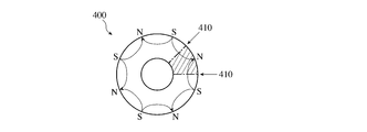
- the magnetic particles are oriented in the circumferential direction between the magnetic poles and have a polar anisotropic orientation as shown in FIG.
- the configuration can be the same as 400. That is, the arc-shaped magnet having polar anisotropy orientation according to the present invention has a structure (part indicated by hatching in FIG. 11) obtained by cutting the ring magnet 400 at a gap 410 between the magnetic poles 410. ing.
- the arc magnet having polar anisotropy according to the present invention is preferably substantially composed of R-TM-B.
- R is at least one rare earth element including Y, and preferably necessarily contains at least one of Nd, Dy, and Pr.
- TM is at least one of transition metals, and is preferably Fe.
- the arc-shaped magnet made of R-TM-B preferably has a composition of 24 to 34 mass% R, 0.6 to 1.8 mass% B, and the balance Fe. When the R content is less than 24% by mass, the residual magnetic flux density Br and the coercive force iHc decrease.
- the region of the rare earth-rich phase inside the sintered body increases and the residual magnetic flux density Br decreases, and the shape of the region becomes coarse and the corrosion resistance decreases.
- the B content is less than 0.6% by mass, the R 2 Fe 14 B phase, which is the main phase, is not sufficiently formed, and an R 2 Fe 17 phase having soft magnetic properties is generated, resulting in a decrease in coercive force.
- the B content exceeds 1.8% by mass, the B-rich phase, which is a nonmagnetic phase, increases and the residual magnetic flux density Br decreases.
- Fe may be partially substituted with Co, and may contain elements such as Al, Si, Cu, Ga, Nb, Mo, and W in an amount of about 3% by mass or less.
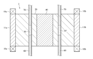
- the mold 1 includes a die 20 made of a nonmagnetic cemented carbide disposed in a parallel magnetic field M formed by a pair of opposing magnetic field coils 10a and 10b and coil cores 11a and 11b, and an inner part provided in the die 20
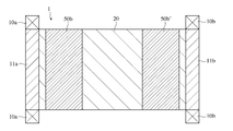
- a cavity 30 having an arc-shaped cross section having an arc wall 31, an outer arc wall 32, and two side walls 33a and 33b, and a central ferromagnetic body disposed on the outer arc wall 32 side of the cavity 30 and spaced from the cavity 30 40 and a pair of side ferromagnets 50a and 50b arranged on the side walls 33a and 33b of the cavity 30 so as to be spaced apart from the cavity 30 and symmetrically with respect to the cavity 30.
- the cavity 30 is arranged so that a radial direction D at the center in the circumferential direction is parallel to the direction of the parallel magnetic field M, and the central ferromagnetic body 40 has a direction perpendicular to the parallel magnetic field M in plan view.
- the width W1 of the cavity 30 is smaller than the width W2 of the cavity 30 in the direction perpendicular to the parallel magnetic field M (see FIG. 4), and the pair of side ferromagnets 50a and 50b is composed of the pair of side ferromagnets.
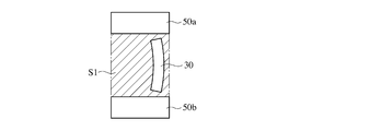
- the cavity 30 is arranged so as to be included in the region S1 sandwiched between the bodies 50a and 50b (see FIG. 5 (a)).
- the coil core 11a and the side ferromagnetic bodies 50a and 50b may be in contact with each other.
- the mold of the present invention has a structure comprising at least one arc-shaped cavity 30, a single central ferromagnet 40, and a pair of side ferromagnets 50a and 50b in a parallel magnetic field M. It is preferably symmetrical with respect to the AA cross section shown in FIG. That is, the cavity 30 and the central ferromagnetic body 40 have a shape symmetrical to the AA cross section, and the pair of side ferromagnetic bodies 50a and 50b are arranged symmetrically to the AA cross section. Is preferred.
- a plane that passes through the midpoint of the central ferromagnetic body 40 in the direction of the parallel magnetic field M and is perpendicular to the parallel magnetic field M (shown by a one-dot chain line C in FIG. 2 (a)).
- another cavity 30 ′ having an arcuate cross section and another pair of side ferromagnetic bodies 50 a ′ and 50 b ′ are provided.
- the central ferromagnet 40 is common to the cavities 30 and 30 ′ and has a symmetrical shape on the plane indicated by the alternate long and short dash line C.
- the die 20 is made of a nonmagnetic cemented carbide. Specifically, WC system is preferable.
- the shape of the cavity 30 is such that a sintered body formed by sintering a molded body molded by the mold 1 including the cavity 30 has a shape close to a shape obtained by cutting out a part of the ring magnet. It is preferable to set to.
- the center angle and the center point of the inner arc and the outer arc respectively corresponding to the inner arc wall 31 and the outer arc wall 32 of the cavity 30 take into account deformation during sintering of the molded body.
- the shape after sintering is appropriately set within the scope of the present invention so that the desired shape is obtained.
- the radii of the inner arc and the outer arc in the cross section of the cavity 30 can be set according to the intended use of the obtained arc-shaped magnet.
- the radius of the outer arc may be set larger than the inner arc
- the radius of the outer arc may be set smaller than the inner arc.
- FIG. 3 (a) and FIG. 3 (b) show examples of cross sections of cavities for forming arc-shaped magnets.
- the cavity shown in FIG. 3 (a) is an example in which the central angles of the inner arc 31a and the outer arc 32a in the cross section are the same and the center points forming each arc coincide with each other, and the cavity shown in FIG. 3 (b)
- the cavity 30 has a circular arc shape formed by a lower punch 60 and an upper punch 70, and the upper punch 70 can be detached from the cavity 30.
- the parallel magnetic field M formed by supplying magnetic powder into the cavity 30 and formed by the magnetic field coils 10a and 10b and the coil cores 11a and 11b
- the lower punch 60 and the upper punch 70 cause the direction perpendicular to the parallel magnetic field M.
- the magnetic powder is compression molded to obtain a molded body.
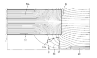
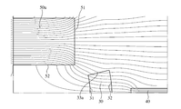
- FIG. 6 (a) is an enlarged view of the region R surrounded by the two-dot chain line in FIG. 2 (a), and shows the state of the magnetic field when a parallel magnetic field is applied.
- the side ferromagnet 50a focuses the magnetic field generated by the magnetic field coils 10a and 10b as shown in FIG. 6 (a), and most of the focused magnetic field is from the end face 51 of the side ferromagnet 50a.
- part of the magnetic field exits from the side surface 52 of the side ferromagnet 50a, enters the cavity 30 substantially perpendicular to the side wall 33a of the cavity 30, and passes through the magnetic powder in the cavity 30.
- the arc-shaped magnet formed in the magnetic field by the mold 1 is The orientation is close to the orientation between the magnetic poles of the ring-shaped polar anisotropic magnet.
- the shape of the side ferromagnets 50a, 50b and the central ferromagnet 40 can be any shape as long as the direction of the magnetic field can be controlled as described above. Although it is good, as shown in FIG. 2 (a), in the plan view, a quadrangle is preferable, and a rectangle is more preferable.
- the rectangular shape facilitates the processing of the side ferromagnets 50a and 50b and the central ferromagnet 40 and the hole of the nonmagnetic cemented carbide die that accommodates them, and is advantageous in terms of strength.
- the central ferromagnetic body 40 has a width W1 in a direction perpendicular to the parallel magnetic field M in a plan view, and is perpendicular to the parallel magnetic field M of the cavity 30.
- the width W2 in the direction By making it smaller than the width W2 in the direction, the magnetic field flowing out from the outer arc wall 32 of the cavity 30 can be concentrated in the center of the outer arc wall 32, and the arc-shaped magnet obtained by molding is the ring
- the orientation is close to the orientation between the magnetic poles of the pole-shaped anisotropic magnet.
- a preferable range of the width W1 is 10 to 30% of the width W2.
- the central ferromagnet 40 is disposed on a radial line passing through the midpoint in the circumferential direction of the cavity 30 in a plan view and is spaced apart from the cavity 30 and has a symmetrical shape with respect to this line. Preferably there is.
- the magnetic field at the center in the circumferential direction of the cavity 30 is in the same direction as the parallel magnetic field M.
- the circle on the outer arc surface An arc-shaped magnet having magnetic powder oriented in the radial direction at the center in the circumferential direction can be obtained. The closer the distance between the central ferromagnet 40 and the central part of the arc of the cavity, the narrower the surface magnetic flux density waveform of the magnet, the narrower the sinusoidal wave, and the farther the sine wave swells.
- the pair of side ferromagnets 50a and 50b is configured so that the cavity 30 is included in a region S1 sandwiched between the pair of side ferromagnets 50a and 50b.
- the magnetic field emitted from the side surface 52 of the side ferromagnetic body 50a enters the cavity 30 substantially perpendicular to the side wall 33a of the cavity 30.
- the magnetic field can be controlled.
- the magnetic field emitted from the side surface 52 of the side ferromagnetic member 50a does not enter the cavity 30 from the side wall 33a of the cavity 30, but enters the inner arc wall 31, while the side wall of the cavity 30
- the magnetic field emitted from the end face 51 of the side ferromagnetic member 50a enters the side 33a obliquely with respect to the side wall 33a.
- the distance between the cavity 30 and the side ferromagnets 50a and 50b is preferably close. When this distance increases, the surface magnetic flux density waveform of the arc-shaped magnet obtained tends to swell with respect to the sine wave, which is not desirable.
- the distance between the central ferromagnet 40 and the cavity 30 and the distance between the side ferromagnets 50a and 50b and the cavity 30 need to be separated from each other to some extent from the viewpoint of the strength of the mold 1. Since the ferromagnetic material is generally low in strength, if the distance from the cavity 30 is too narrow, the die may be deformed during compression molding, and a crack may occur in the ferromagnetic material. Therefore, it is necessary to dispose these magnetic bodies and the cavity 30 at a sufficient distance so as not to cause deformation of the die due to the stress applied to the carbide die during pressing.
- the angle ⁇ (see FIG. 7 (a)) formed by the surface of the side wall 33a of the cavity 30 and the side surface 52 of the side ferromagnetic body 50a is preferably 0 ⁇ ⁇ .
- the direction in which the magnetic field emitted from the side surface 52 of the side ferromagnetic material 50a enters the side wall 33a of the cavity 30 can be adjusted to some extent by changing the strength of the magnetic field, so that the angle ⁇ is 0 ⁇ ⁇ . 6 (a), it is possible to make the magnetic field emitted from the side surface 52 of the side ferromagnetic body 50a substantially perpendicular to the side wall 33a of the cavity 30 as shown in FIG. is there.
- the angle ⁇ is larger than 0 °.
- the component in the parallel magnetic field direction of the magnetic field can be reduced when it exits from the side surface 52 of the side ferromagnet 50a. Even if this vector is added, the magnetic field emitted from the side surface 52 of the side ferromagnetic material 50a can enter the side wall 33a of the cavity 30 perpendicularly.
- the upper limit of ⁇ is preferably 50 ° ( ⁇ ⁇ 50 °).
- central ferromagnet 40 and the side ferromagnets 50a and 50b general magnetic materials can be used, and S45C, magnetic cemented carbide, etc. are particularly suitable.
- the pulverization of the magnetic powder is preferably carried out separately in coarse pulverization and fine pulverization.
- the coarse pulverization is preferably performed by a stamp mill, a jaw crusher, a brown mill, a disk mill, a hydrogen pulverization or the like, and the fine pulverization is preferably performed by a jet mill, a vibration mill, a ball mill or the like.
- the pulverized particle size is preferably 2 to 8 ⁇ m (FSSS).
- the strength of the parallel magnetic field applied to the cavity 30 to orient the magnetic powder is preferably 159 kA / m or more, more preferably 239 kA / m or more. When the strength of the orientation magnetic field is less than 159 kA / m, the orientation of the magnetic powder is insufficient and good magnetic properties cannot be obtained.
- the strength of the orientation magnetic field is appropriately determined in consideration of the state of polar anisotropic orientation of the arc-shaped magnet obtained at the magnetic field strength or higher.
- the molding pressure is preferably 0.5 to 2 ton / cm 2 . If it is less than 0.5 ton / cm 2 , the strength of the molded product tends to be weakened, and if it exceeds 2 ton / cm 2 , the orientation of the magnetic powder is disturbed and the magnetic properties are deteriorated.
- Sintering Sintering is preferably performed at 1000 to 1150 ° C. in a vacuum or an argon atmosphere. If it is less than 1000 ° C., the required density cannot be obtained due to insufficient sintering, and the magnetic properties deteriorate. Above 1150 °C, oversintering causes deformation and deterioration of magnetic properties.
- Sintering is performed by placing a Mo plate in a heat-resistant container using Mo and placing a compact on it.
- Mo plate is a rolled material and the surface roughness is low, seizure between the sintered body and the Mo plate is likely to occur, and the sintered magnet may be deformed in the process of shrinkage accompanying the sintering.
- the surface roughness (JISR6001-1983) of the Mo plate after blasting is preferably 5 ⁇ m to 100 ⁇ m, more preferably 7 ⁇ m to 50 ⁇ m in Rmax.
- it is 10 ⁇ m to 30 ⁇ m. If it is less than 5 ⁇ m, seizure between the sintered body and the Mo plate is likely to occur, and the magnet after sintering is deformed. If it exceeds 100 ⁇ m, the sintered body gets caught in the Mo plate during the shrinkage process, causing deformation. Neodymium oxide or the like can be applied to the Mo plate to prevent seizure of the sintered body and the Mo plate during sintering.
- the sintered body is preferably subjected to a heat treatment.
- the heat treatment may be performed before or after processing described later.
- the obtained sintered body is preferably processed into an outer arc surface, an inner arc surface, and an end surface to the required dimensions as required.
- existing equipment such as an outer diameter polishing machine, an inner diameter polishing machine, a flat surface polishing machine, or a shape processing machine can be used as appropriate.
- Surface treatments such as plating, painting, vacuum deposition of aluminum, and chemical conversion treatment can be performed as necessary.
- a circular magnet having polar anisotropy orientation is bonded around the rotor yoke with an adhesive to produce a brushless motor rotor.
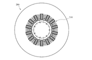
- a magnetized yoke 200 having a coil 210 shown in FIG. 9 is used (the arrow indicates the direction of a magnetic field applied when magnetizing).
- Magnetization is performed on the arc-shaped magnet.
- the magnetizing conditions are preferably a capacitor capacity of 1000 to 2000 ⁇ F, a charging voltage of 1000 to 2500 ⁇ V, and a magnetizing current of 8 to 25 ⁇ kVA. If the magnetization current is less than 8 kVA, desired magnetization characteristics cannot be obtained after magnetization, and even if magnetization exceeding 25 kVA is performed, no improvement is observed in the magnetic characteristics after magnetization.
- This method can be applied to both dry molding and wet molding. It can also be applied to ferrite magnets, Sm-Co magnets, or resin-containing magnets.
- Example 1 Nd—Fe—B magnetic powder having a composition comprising Nd: 20.5 mass%, Dy: 6.2 mass%, Pr: 5.5 mass%, B: 1.0 mass%, the balance Fe and inevitable impurities was produced by a known method.
- the obtained magnetic powder is made into a cavity having a circular arc cross section (an outer arc with a radius of 50 mm, an inner arc with a radius of 37 mm, and a central angle of 25.7) provided in the die of the mold shown in FIGS. 2 (a) to 2 (c). °).
- the side ferromagnet having the shape shown in FIG. 7 (a) was used.
- the magnetic powder is applied at a molding pressure of 1 t / cm 2 while applying a parallel magnetic field having a strength of 239 to 319 kA / m so that the radial direction at the center in the circumferential direction of the cavity coincides with the magnetic field direction.
- the obtained compact was sintered and heat-treated, and then processed into a size having an outer arc radius of 80 mm, an inner arc radius of 64 mm, and a central angle of 25.7 ° to obtain an arc-shaped sintered magnet.
- Example 2 An arc-shaped sintered magnet was obtained in the same manner as in Example 1 except that the side ferromagnetic material was changed to the shape shown in FIG. 7 (b).
- Example 3 After sintering, the polar anisotropy was the same as in Example 1 except that the arrangement of the central ferromagnetic material, the side ferromagnetic material, and the cavity was adjusted so that the surface magnetic flux density waveform of the magnet became closer to a sine waveform.
- a polar anisotropic magnet molded body having an orientation was prepared.
- Comparative Example An arc-shaped sintered magnet was obtained in the same manner as in Example 1 except that no central ferromagnet and side ferromagnet were provided.
- the inner arc surface is pasted on the cylindrical yoke to form a ring shape, and for the ring magnet of the reference example, the cylindrical yoke is inserted on the inner peripheral surface.
- a magnetizing yoke 200 having a 14-pole coil 210 as shown in FIG. 9 is used (the arrow indicates the direction of the magnetic field applied when magnetizing) to match the number of poles. Magnetization was performed and the surface magnetic flux density waveform was measured. The results are shown in FIG. FIG. 8 shows a waveform of 0.5 poles extracted from 14 poles.
- the arc-shaped sintered magnet of the comparative example has a waveform close to a trapezoid, whereas the arc-shaped sintered magnets of Examples 1 to 3 are extremely different from the reference example.
- the waveform was close to that of an anisotropic ring magnet.
- the arc-shaped sintered magnet of Example 2 manufactured using the side ferromagnetic material having the shape shown in FIG. 7 (b) is a surface magnetic flux in which the side part (near the magnetic pole) is slightly swollen compared to Example 1. It became a density waveform.
- the arc-shaped sintered magnet of Example 3 has a waveform that substantially matches the polar anisotropic ring magnet of the reference example, indicating that it has an ideal polar anisotropic orientation.
- the rotating machine When the rotating machine is configured using the sintered magnet of the comparative example, it is expected that the cogging torque is high. However, when the sintered magnets of Examples 1 to 3 of the present invention are used, the rotating speed is low. We can expect a chance.
Landscapes
- Engineering & Computer Science (AREA)
- Power Engineering (AREA)
- Mechanical Engineering (AREA)
- Manufacturing & Machinery (AREA)
- Physics & Mathematics (AREA)
- Electromagnetism (AREA)
- Manufacturing Cores, Coils, And Magnets (AREA)
- Powder Metallurgy (AREA)
- Hard Magnetic Materials (AREA)
Abstract
Description
対向する一対の磁場コイルにより形成される平行磁場中に配置される非磁性超硬合金からなるダイスと、
前記ダイスに設けられた内弧壁、外弧壁及び2つの側壁を有する断面円弧状のキャビティと、
前記キャビティの外弧壁側に、前記キャビティから離間して配置された中央強磁性体と、
前記キャビティの各側壁側に、それぞれ前記キャビティから離間して、前記キャビティに対して対称に配置された一対の側部強磁性体とを有し、
前記キャビティは、円周方向中央における半径方向が前記平行磁場方向と一致するように配置されており、
前記中央強磁性体は、平面視で、前記平行磁場と垂直な方向の幅が、前記キャビティの、前記平行磁場と垂直な方向の幅よりも小さく、
前記一対の側部強磁性体は、前記一対の側部強磁性体によって挟まれた領域内に前記キャビティが含まれるように配置されていることを特徴とする。
対向する一対の磁場コイルにより形成される平行磁場中に配置される非磁性超硬合金からなるダイスと、
前記ダイスに設けられた内弧壁、外弧壁及び2つの側壁を有する断面円弧状のキャビティと、
前記キャビティの外弧壁側に、前記キャビティから離間して配置された中央強磁性体と、
前記キャビティの各側壁側に、それぞれ前記キャビティから離間して、前記キャビティに対して対称に配置された一対の側部強磁性体とを有し、
前記キャビティは、円周方向中央における半径方向が前記平行磁場方向と一致するように配置されており、
前記中央強磁性体は、平面視で、前記平行磁場と垂直な方向の幅が、前記キャビティの、前記平行磁場と垂直な方向の幅よりも小さく、
前記一対の側部強磁性体は、前記一対の側部強磁性体によって挟まれた領域内に前記キャビティが含まれるように配置されている金型を使用し、前記キャビティに充填した磁粉に対して前記平行磁場をかけながら圧縮成形することを特徴とする。
本発明の極異方性配向を有する円弧状磁石は、図1(a)に示すように、半径方向に幅を有する円弧状の断面を有する柱状であり、図1(b)に示すように、断面における磁粉の配向方向が、円弧状磁石100の円周方向の端面103a,103bにおいては端面に対して垂直方向(円周方向)であり、外弧面102の円周方向中央においては半径方向である。このような配向にすることにより、この円弧状磁石1をリング状に組み立てたときに、磁極間において円周方向に磁粉が配向した、図11に示すような極異方性配向を有するリング磁石400と同様の構成とすることができる。すなわち、本発明の極異方性配向を有する円弧状磁石は、前記リング磁石400をその磁極間410と磁極間410とで切断してなる構造(図11に斜線で示した部分)を有している。
(1)全体構成
極異方性配向を有する円弧状磁石は、図2(a)~図2(c)に示す成形装置を用いて磁場中で形成する。金型1は、対向する一対の磁場コイル10a,10b及びコイルコア11a,11bにより形成される平行磁場M中に配置される非磁性超硬合金からなるダイス20と、前記ダイス20に設けられた内弧壁31、外弧壁32及び2つの側壁33a,33bを有する断面円弧状のキャビティ30と、前記キャビティ30の外弧壁32側に、前記キャビティ30から離間して配置された中央強磁性体40と、前記キャビティ30の各側壁33a,33b側に、それぞれ前記キャビティ30から離間して、前記キャビティ30に対して対称に配置された一対の側部強磁性体50a,50bとを有する。前記キャビティ30は、円周方向中央における半径方向Dが前記平行磁場M方向と平行になるように配置されており、前記中央強磁性体40は、平面視で、前記平行磁場Mと垂直な方向の幅W1が、前記キャビティ30の、前記平行磁場Mと垂直な方向の幅W2よりも小さく(図4参照)、前記一対の側部強磁性体50a,50bは、前記一対の側部強磁性体50a,50bによって挟まれた領域S1内に前記キャビティ30が含まれるように、配置されている(図5(a)参照)。コイルコア11aと側部強磁性体50a,50bとは接触していても良い。
前記キャビティ30の形状は、前記キャビティ30を含む金型1によって成型された成型体を焼結してなる焼結体が、リング磁石の一部分を切り出した形状に近い形状になるように設定するのが好ましい。前記キャビティ30の断面形状において、前記キャビティ30の内弧壁31及び外弧壁32にそれぞれ対応する内弧及び外弧の各中心角及び中心点は、成形体の焼結時の変形を加味し、焼結後の形状が目的の形状となるように、本発明の範囲内で適宜設定される。前記キャビティ30の断面における前記内弧及び前記外弧の半径は、得られる円弧状磁石の使用目的に応じて設定することができる。円弧状磁石の使用目的や形状を考慮し、内弧に対して外弧の半径を大きく設定しても良く、また内弧に対して外弧の半径を小さく設定しても良い。図3(a)及び図3(b)は、円弧状磁石を形成するためのキャビティの断面の例を示す。図3(a)に示すキャビティは、断面における内弧31a及び外弧32aの中心角が同じでかつ各弧を形成する中心点が一致している例であり、図3(b)に示すキャビティは、断面における内弧31a及び外弧32aの中心角θ1及びθ2が異なっている例である。
側部強磁性体50a,50b及び中央強磁性体40の形状は、前述のように磁界の方向を制御できるものであればどのようなものでも良いが、図2(a)に示すように、平面視で、四角形であるのが好ましく、矩形であるのがより好ましい。矩形とすることにより、側部強磁性体50a,50b及び中央強磁性体40の加工、並びにそれらを収める非磁性超硬合金ダイスの穴の加工が容易であり、強度的にも有利である。
(1)磁粉の準備
磁粉の粉砕は、粗粉砕と微粉砕とに分けて行うのが好ましい。粗粉砕は、スタンプミル、ジョークラッシャー、ブラウンミル、ディスクミル、水素粉砕等で行うのが好ましく、微粉砕は、ジェットミル、振動ミル、ボールミル等で行うのが好ましい。いずれも酸化を防ぐために、有機溶媒や不活性ガスを用いて非酸化雰囲気中で行うのが好ましい。粉砕粒度は2~8μm(F.S.S.S.)が好ましい。2μm未満では磁粉の活性が高く酸化が激しく起こるため焼結時の変形が大であり、磁気特性も悪化する。8μm超では焼結後の結晶粒径が大きくなり容易に磁化反転が起こり、保磁力の低下を招く。
(2)成形
磁粉を配向させるためにキャビティ30に印可する平行磁場の強さは、好ましくは159 kA/m以上であり、より好ましくは239 kA/m以上である。配向磁場の強さが159 kA/m未満では、磁粉の配向が不十分であり良好な磁気特性が得られない。配向磁場の強さは前記磁場強度以上で得られる円弧状磁石の極異方性配向の状況を加味し手適宜決定する。成形圧力は0.5~2 ton/cm2が望ましい。0.5 ton/cm2未満では成形体の強度が弱くなりこわれやすい、また2 ton/cm2超では磁粉の配向が乱れ、磁気特性が低下する。
焼結は、真空又はアルゴン雰囲気中で、1000~1150℃で行うのが好ましい。1000℃未満では焼結不足により、必要とされる密度が得られず、磁気特性が低下する。1150℃超では過焼結により、変形や磁気特性の低下が発生する。
焼結の後、前記焼結体に熱処理を施すのが好ましい。熱処理は、後述の加工前に行っても良いし加工後に行っても良い。
公知の方法で、Nd:20.5質量%、Dy:6.2質量%、Pr:5.5質量%、B:1.0質量%、残部Fe及び不可避不純物からなる組成のNd-Fe-B磁性粉を製造した。得られた磁粉を、図2(a)~図2(c)に示す金型のダイスに設けられた断面円弧状のキャビティ(半径50 mmの外弧、半径37 mmの内弧及び中心角25.7°)に供給した。側部強磁性体は、図7(a)に示す形状のものを用いた。前記金型に、前記キャビティの円周方向中央における半径方向と、磁場方向とが一致するように、239~319 kA/mの強度の平行磁場をかけながら成形圧1 t/cm2で前記磁粉の成形を行った。得られた成形体を焼結、熱処理した後、外弧半径80 mm、内弧半径64 mm及び中心角25.7°の大きさに加工し、円弧状の焼結磁石を得た。
側部強磁性体を、図7(b)に示す形状に変更した以外は、実施例1と同様にして、円弧状の焼結磁石を得た。
焼結後に、磁石の表面磁束密度波形がさらに正弦波形に近くなるように、中央強磁性体、側部強磁性体、キャビティの配置を調節した以外は実施例1と同様にして極異方性配向を有する極異方性磁石成形体を作製した。
中央強磁性体及び側部強磁性体を全く設けない以外は、実施例1と同様にして、円弧状の焼結磁石を得た。
実施例1と同じ方法で作製した磁性粉を用いて、既存の極異方性配向を有するリング磁石を成形するための金型(外周14極、外径100 mm及び内径74 mm)で成形し、焼結及び熱処理を行った。焼結体は、外径80 mm及び内径64 mmに加工し、極異方性配向を有するリング磁石を得た。成形は、特開昭59-216453号に記載の方法で行った。
Claims (8)
- 対向する一対の磁場コイルにより形成される平行磁場中に配置される非磁性超硬合金からなるダイスと、
前記ダイスに設けられた内弧壁、外弧壁及び2つの側壁を有する断面円弧状のキャビティと、
前記キャビティの外弧壁側に、前記キャビティから離間して配置された中央強磁性体と、
前記キャビティの各側壁側に、それぞれ前記キャビティから離間して、前記キャビティに対して対称に配置された一対の側部強磁性体とを有する金型であって、
前記キャビティは、円周方向中央における半径方向が前記平行磁場方向と一致するように配置されており、
前記中央強磁性体は、平面視で、前記平行磁場と垂直な方向の幅が、前記キャビティの、前記平行磁場と垂直な方向の幅よりも小さく、
前記一対の側部強磁性体は、前記一対の側部強磁性体によって挟まれた領域内に前記キャビティが含まれるように配置されていることを特徴とする極異方性配向を有する円弧状磁石を磁場中成形するための金型。 - 請求項1に記載の金型において、前記中央強磁性体が、平面視で、前記キャビティの円周方向中点を通る半径方向の線上に配置されており、前記線に対して対称な形状であることを特徴とする金型。
- 請求項1又は2に記載の金型において、前記中央強磁性体が、前記中央強磁性体の前記磁場方向中点を通り、前記磁場方向に垂直な面に対称な形状であり、前記面に対称に、もう一つのキャビティ及びもう一対の側部強磁性体が配置されていることを特徴とする金型。
- 請求項1~3のいずれかに記載の金型において、前記中央強磁性体及び/又は前記各側部強磁性体が、平面視で矩形状であることを特徴とする金型。
- 請求項1~4のいずれかに記載の金型において、前記キャビティの各側壁面と、前記各側壁に対向する前記各側部強磁性体の面とのなす角度が、0°より大きいことを特徴とする金型。
- 極異方性配向を有する円弧状磁石を製造する方法であって、
対向する一対の磁場コイルにより形成される平行磁場中に配置される非磁性超硬合金からなるダイスと、
前記ダイスに設けられた内弧壁、外弧壁及び2つの側壁を有する断面円弧状のキャビティと、
前記キャビティの外弧壁側に、前記キャビティから離間して配置された中央強磁性体と、
前記キャビティの各側壁側に、それぞれ前記キャビティから離間して、前記キャビティに対して対称に配置された一対の側部強磁性体とを有し、
前記キャビティは、円周方向中央における半径方向が前記平行磁場方向と一致するように配置されており、
前記中央強磁性体は、平面視で、前記平行磁場と垂直な方向の幅が、前記キャビティの、前記平行磁場と垂直な方向の幅よりも小さく、
前記一対の側部強磁性体は、前記一対の側部強磁性体によって挟まれた領域内に前記キャビティが含まれるように配置されている金型を使用し、前記キャビティに充填した磁粉に対して前記平行磁場をかけながら圧縮成形することを特徴とする方法。 - 請求項6記載の方法において、前記磁粉が、実質的にR-TM-B(ただし、RはYを含む希土類元素の少なくとも1種、TMは遷移金属の少なくとも1種)からなることを特徴とする方法。
- 請求項6又は7に記載の方法によって製造されたことを特徴とする極異方性配向を有する円弧状磁石。
Priority Applications (4)
| Application Number | Priority Date | Filing Date | Title |
|---|---|---|---|
| JP2012550894A JP5904124B2 (ja) | 2010-12-28 | 2011-12-21 | 極異方性配向を有する円弧状磁石、その製造方法、及びそれを製造するための金型 |
| DE112011104619T DE112011104619T5 (de) | 2010-12-28 | 2011-12-21 | Bogenförmiger Magnet mit polar-anisotroper Ausrichtung und Verfahren und Bildungsform zu seiner Herstellung |
| CN201180063068.9A CN103299381B (zh) | 2010-12-28 | 2011-12-21 | 具有极性各向异性取向的圆弧状磁铁、其制造方法以及用于制造其的模具 |
| US13/976,254 US9646751B2 (en) | 2010-12-28 | 2011-12-21 | Arcuate magnet having polar-anisotropic orientation, and method and molding die for producing it |
Applications Claiming Priority (4)
| Application Number | Priority Date | Filing Date | Title |
|---|---|---|---|
| JP2010293954 | 2010-12-28 | ||
| JP2010-293954 | 2010-12-28 | ||
| JP2011-166721 | 2011-07-29 | ||
| JP2011166721 | 2011-07-29 |
Publications (1)
| Publication Number | Publication Date |
|---|---|
| WO2012090841A1 true WO2012090841A1 (ja) | 2012-07-05 |
Family
ID=46382947
Family Applications (1)
| Application Number | Title | Priority Date | Filing Date |
|---|---|---|---|
| PCT/JP2011/079737 Ceased WO2012090841A1 (ja) | 2010-12-28 | 2011-12-21 | 極異方性配向を有する円弧状磁石、その製造方法、及びそれを製造するための金型 |
Country Status (5)
| Country | Link |
|---|---|
| US (1) | US9646751B2 (ja) |
| JP (1) | JP5904124B2 (ja) |
| CN (1) | CN103299381B (ja) |
| DE (1) | DE112011104619T5 (ja) |
| WO (1) | WO2012090841A1 (ja) |
Cited By (6)
| Publication number | Priority date | Publication date | Assignee | Title |
|---|---|---|---|---|
| EP3002854A2 (en) | 2014-09-30 | 2016-04-06 | Nichia Corporation | Bonded magnet and production method thereof |
| JP2018019081A (ja) * | 2016-07-15 | 2018-02-01 | 日立金属株式会社 | 焼結体、その製造方法、プレス装置および樹脂モールドリング |
| US10573440B2 (en) | 2015-11-19 | 2020-02-25 | Nitto Denko Corporation | Rare-earth permanent magnet-forming sintered body, and rare-earth permanent magnet obtained by magnetizing said sintered body |
| JP2021097224A (ja) * | 2019-12-13 | 2021-06-24 | 煙台首鋼磁性材料株式有限公司 | ラジアル配向焼結Nd−Fe−B系瓦状磁性体の製造装置、製造方法、及び当該装置又は方法によって製造されるラジアル配向焼結Nd−Fe−B系瓦状磁性体 |
| JPWO2022138765A1 (ja) * | 2020-12-25 | 2022-06-30 | ||
| JP2023046501A (ja) * | 2021-09-24 | 2023-04-05 | 株式会社プロテリアル | 粉末成形体取り出し装置および粉末プレスシステム |
Families Citing this family (4)
| Publication number | Priority date | Publication date | Assignee | Title |
|---|---|---|---|---|
| DE102014202848A1 (de) * | 2014-02-17 | 2015-08-20 | Robert Bosch Gmbh | Spritzwerkzeug zur Herstellung eines Permanentmagneten |
| US10773461B2 (en) * | 2016-05-23 | 2020-09-15 | Iain Grant Kirk McDonald | Magnetic plastic induction |
| CN112017855B (zh) * | 2020-07-30 | 2025-02-28 | 烟台正海磁性材料股份有限公司 | 一种极异方性取向磁石及其制造方法和应用 |
| CN118969433A (zh) * | 2024-10-16 | 2024-11-15 | 宁波金鸡强磁股份有限公司 | 一种弧形取向的磁体及其应用 |
Citations (3)
| Publication number | Priority date | Publication date | Assignee | Title |
|---|---|---|---|---|
| JPS628506A (ja) * | 1985-07-05 | 1987-01-16 | Tohoku Metal Ind Ltd | 半径方向2極磁石及びその製造装置 |
| JPH05129127A (ja) * | 1991-10-30 | 1993-05-25 | Kawasaki Steel Corp | 異方性セグメント型磁石 |
| JPH05168201A (ja) * | 1991-12-11 | 1993-07-02 | Asmo Co Ltd | 回転電機用配向装置 |
Family Cites Families (15)
| Publication number | Priority date | Publication date | Assignee | Title |
|---|---|---|---|---|
| DE2629990C3 (de) | 1976-07-03 | 1981-01-15 | Magnetfabrik Bonn Gmbh Vorm. Gewerkschaft Windhorst, 5300 Bonn | Preßwerkzeug für anisotrope Dauermagnete |
| JPS59216453A (ja) | 1983-05-20 | 1984-12-06 | Hitachi Metals Ltd | 円筒状永久磁石の製造方法 |
| EP0304054B1 (en) * | 1987-08-19 | 1994-06-08 | Mitsubishi Materials Corporation | Rare earth-iron-boron magnet powder and process of producing same |
| US5204569A (en) * | 1990-02-07 | 1993-04-20 | Asmo Co., Ltd. | Anisotropic magnet for rotary electric machine |
| US5273571A (en) * | 1992-12-21 | 1993-12-28 | Valenite Inc. | Nonmagnetic nickel tungsten cemented carbide compositions and articles made from the same |
| JP2002134314A (ja) | 2000-10-20 | 2002-05-10 | Toda Kogyo Corp | 異方性セグメント形状磁石及びその成形金型磁気回路装置 |
| JP2003017309A (ja) | 2001-03-30 | 2003-01-17 | Hitachi Metals Ltd | 焼結リング磁石およびその製造方法 |
| JP2003199274A (ja) | 2001-12-25 | 2003-07-11 | Hitachi Ltd | 回転子とその製造法及び回転機 |
| US6992553B2 (en) | 2002-06-18 | 2006-01-31 | Hitachi Metals, Ltd. | Magnetic-field molding apparatus |
| JP3997427B2 (ja) | 2002-06-18 | 2007-10-24 | 日立金属株式会社 | 極異方性リング磁石の製造に用いる磁場中成形装置 |
| KR100579914B1 (ko) * | 2003-08-13 | 2006-05-15 | 자화전자 주식회사 | 적층극이방복합자석의 제조방법 |
| JP4425682B2 (ja) | 2004-03-30 | 2010-03-03 | 信越化学工業株式会社 | 異方性磁石の製造に用いる金型、成形機、方法及び得られる磁石 |
| JP4471698B2 (ja) * | 2004-03-30 | 2010-06-02 | 信越化学工業株式会社 | 金型、永久磁石磁場成形機及び永久磁石の製造方法 |
| JP4791013B2 (ja) * | 2004-07-22 | 2011-10-12 | 三菱電機株式会社 | ブラシレスモータ |
| JP4508019B2 (ja) * | 2005-07-13 | 2010-07-21 | パナソニック株式会社 | 異方性ボンドシート磁石およびその製造装置 |
-
2011
- 2011-12-21 WO PCT/JP2011/079737 patent/WO2012090841A1/ja not_active Ceased
- 2011-12-21 DE DE112011104619T patent/DE112011104619T5/de not_active Withdrawn
- 2011-12-21 US US13/976,254 patent/US9646751B2/en active Active
- 2011-12-21 JP JP2012550894A patent/JP5904124B2/ja active Active
- 2011-12-21 CN CN201180063068.9A patent/CN103299381B/zh active Active
Patent Citations (3)
| Publication number | Priority date | Publication date | Assignee | Title |
|---|---|---|---|---|
| JPS628506A (ja) * | 1985-07-05 | 1987-01-16 | Tohoku Metal Ind Ltd | 半径方向2極磁石及びその製造装置 |
| JPH05129127A (ja) * | 1991-10-30 | 1993-05-25 | Kawasaki Steel Corp | 異方性セグメント型磁石 |
| JPH05168201A (ja) * | 1991-12-11 | 1993-07-02 | Asmo Co Ltd | 回転電機用配向装置 |
Cited By (13)
| Publication number | Priority date | Publication date | Assignee | Title |
|---|---|---|---|---|
| US9583244B2 (en) | 2014-09-30 | 2017-02-28 | Nichia Corporation | Bonded magnet, bonded magnet component, and bonded magnet production method |
| US10832863B2 (en) | 2014-09-30 | 2020-11-10 | Nichia Corporation | Bonded magnet, bonded magnet component, and bonded magnet production method |
| EP3002854A2 (en) | 2014-09-30 | 2016-04-06 | Nichia Corporation | Bonded magnet and production method thereof |
| US11735358B2 (en) | 2014-09-30 | 2023-08-22 | Nichia Corporation | Bonded magnet, bonded magnet component, and bonded magnet production method |
| US10573440B2 (en) | 2015-11-19 | 2020-02-25 | Nitto Denko Corporation | Rare-earth permanent magnet-forming sintered body, and rare-earth permanent magnet obtained by magnetizing said sintered body |
| JP2018019081A (ja) * | 2016-07-15 | 2018-02-01 | 日立金属株式会社 | 焼結体、その製造方法、プレス装置および樹脂モールドリング |
| JP7180963B2 (ja) | 2019-12-13 | 2022-11-30 | 煙台東星磁性材料株式有限公司 | ラジアル配向焼結Nd-Fe-B系瓦状磁性体の製造装置及びその製造方法 |
| JP2021097224A (ja) * | 2019-12-13 | 2021-06-24 | 煙台首鋼磁性材料株式有限公司 | ラジアル配向焼結Nd−Fe−B系瓦状磁性体の製造装置、製造方法、及び当該装置又は方法によって製造されるラジアル配向焼結Nd−Fe−B系瓦状磁性体 |
| JPWO2022138765A1 (ja) * | 2020-12-25 | 2022-06-30 | ||
| WO2022138765A1 (ja) * | 2020-12-25 | 2022-06-30 | 有限会社宮脇工房 | 極異方性磁石の製造方法、磁石集合体の製造方法、極異方性磁石、磁石集合体及び複合磁石集合体 |
| JP7751309B2 (ja) | 2020-12-25 | 2025-10-08 | 有限会社 宮脇工房 | 極異方性磁石の製造方法、磁石集合体の製造方法、極異方性磁石、磁石集合体及び複合磁石集合体 |
| JP2023046501A (ja) * | 2021-09-24 | 2023-04-05 | 株式会社プロテリアル | 粉末成形体取り出し装置および粉末プレスシステム |
| JP7655171B2 (ja) | 2021-09-24 | 2025-04-02 | 株式会社プロテリアル | 粉末成形体取り出し装置および粉末プレスシステム |
Also Published As
| Publication number | Publication date |
|---|---|
| JP5904124B2 (ja) | 2016-04-13 |
| DE112011104619T5 (de) | 2013-10-02 |
| US9646751B2 (en) | 2017-05-09 |
| US20130278367A1 (en) | 2013-10-24 |
| CN103299381B (zh) | 2016-01-20 |
| JPWO2012090841A1 (ja) | 2014-06-05 |
| CN103299381A (zh) | 2013-09-11 |
Similar Documents
| Publication | Publication Date | Title |
|---|---|---|
| JP5904124B2 (ja) | 極異方性配向を有する円弧状磁石、その製造方法、及びそれを製造するための金型 | |
| CN101689424B (zh) | R-tm-b系径向各向异性环状磁铁、该磁铁的制造方法、及用于制造该磁铁的模具、以及无刷电动机用转子 | |
| EP2063438B1 (en) | Production method of a radial anisotropic sintered magnet | |
| CN100498989C (zh) | 放射状各向异性环形磁铁的制造方法 | |
| JP2004120892A (ja) | リング磁石とその製造法及びそれを用いた回転子並びにモータ | |
| WO2005124800A1 (ja) | ラジアル異方性円筒焼結磁石及び永久磁石モータ用円筒多極磁石の製造方法 | |
| JP5089979B2 (ja) | ラジアル異方性円筒焼結磁石、その製造方法及び永久磁石モータ | |
| JP6384543B2 (ja) | 極異方性リング磁石、及びそれを用いた回転子 | |
| JP2010154744A (ja) | 金型、磁場成形機及び永久磁石の製造方法 | |
| JP2004153867A (ja) | ラジアル異方性焼結磁石及びその製造方法並びに磁石ロータ及びモータ | |
| JP4471698B2 (ja) | 金型、永久磁石磁場成形機及び永久磁石の製造方法 | |
| JP3719782B2 (ja) | 表面多極異方性リング磁石の製造方法 | |
| JP3809175B2 (ja) | 表面多極異方性リング磁石 | |
| JP2016158354A (ja) | 極異方性リング磁石、及びそれを用いた回転子 |
Legal Events
| Date | Code | Title | Description |
|---|---|---|---|
| 121 | Ep: the epo has been informed by wipo that ep was designated in this application |
Ref document number: 11852683 Country of ref document: EP Kind code of ref document: A1 |
|
| ENP | Entry into the national phase |
Ref document number: 2012550894 Country of ref document: JP Kind code of ref document: A |
|
| WWE | Wipo information: entry into national phase |
Ref document number: 13976254 Country of ref document: US |
|
| WWE | Wipo information: entry into national phase |
Ref document number: 112011104619 Country of ref document: DE Ref document number: 1120111046197 Country of ref document: DE |
|
| 122 | Ep: pct application non-entry in european phase |
Ref document number: 11852683 Country of ref document: EP Kind code of ref document: A1 |