WO2012086721A1 - ポリテトラフルオロエチレン混合物 - Google Patents
ポリテトラフルオロエチレン混合物 Download PDFInfo
- Publication number
- WO2012086721A1 WO2012086721A1 PCT/JP2011/079715 JP2011079715W WO2012086721A1 WO 2012086721 A1 WO2012086721 A1 WO 2012086721A1 JP 2011079715 W JP2011079715 W JP 2011079715W WO 2012086721 A1 WO2012086721 A1 WO 2012086721A1
- Authority
- WO
- WIPO (PCT)
- Prior art keywords
- ptfe
- polytetrafluoroethylene
- mixture
- powder
- stretched
- Prior art date
- Legal status (The legal status is an assumption and is not a legal conclusion. Google has not performed a legal analysis and makes no representation as to the accuracy of the status listed.)
- Ceased
Links
Images


Classifications
-
- C—CHEMISTRY; METALLURGY
- C08—ORGANIC MACROMOLECULAR COMPOUNDS; THEIR PREPARATION OR CHEMICAL WORKING-UP; COMPOSITIONS BASED THEREON
- C08J—WORKING-UP; GENERAL PROCESSES OF COMPOUNDING; AFTER-TREATMENT NOT COVERED BY SUBCLASSES C08B, C08C, C08F, C08G or C08H
- C08J5/00—Manufacture of articles or shaped materials containing macromolecular substances
- C08J5/18—Manufacture of films or sheets
-
- C—CHEMISTRY; METALLURGY
- C08—ORGANIC MACROMOLECULAR COMPOUNDS; THEIR PREPARATION OR CHEMICAL WORKING-UP; COMPOSITIONS BASED THEREON
- C08L—COMPOSITIONS OF MACROMOLECULAR COMPOUNDS
- C08L27/00—Compositions of homopolymers or copolymers of compounds having one or more unsaturated aliphatic radicals, each having only one carbon-to-carbon double bond, and at least one being terminated by a halogen; Compositions of derivatives of such polymers
- C08L27/02—Compositions of homopolymers or copolymers of compounds having one or more unsaturated aliphatic radicals, each having only one carbon-to-carbon double bond, and at least one being terminated by a halogen; Compositions of derivatives of such polymers not modified by chemical after-treatment
- C08L27/12—Compositions of homopolymers or copolymers of compounds having one or more unsaturated aliphatic radicals, each having only one carbon-to-carbon double bond, and at least one being terminated by a halogen; Compositions of derivatives of such polymers not modified by chemical after-treatment containing fluorine atoms
- C08L27/18—Homopolymers or copolymers or tetrafluoroethene
-
- C—CHEMISTRY; METALLURGY
- C08—ORGANIC MACROMOLECULAR COMPOUNDS; THEIR PREPARATION OR CHEMICAL WORKING-UP; COMPOSITIONS BASED THEREON
- C08J—WORKING-UP; GENERAL PROCESSES OF COMPOUNDING; AFTER-TREATMENT NOT COVERED BY SUBCLASSES C08B, C08C, C08F, C08G or C08H
- C08J2327/00—Characterised by the use of homopolymers or copolymers of compounds having one or more unsaturated aliphatic radicals, each having only one carbon-to-carbon double bond, and at least one being terminated by a halogen; Derivatives of such polymers
- C08J2327/02—Characterised by the use of homopolymers or copolymers of compounds having one or more unsaturated aliphatic radicals, each having only one carbon-to-carbon double bond, and at least one being terminated by a halogen; Derivatives of such polymers not modified by chemical after-treatment
- C08J2327/12—Characterised by the use of homopolymers or copolymers of compounds having one or more unsaturated aliphatic radicals, each having only one carbon-to-carbon double bond, and at least one being terminated by a halogen; Derivatives of such polymers not modified by chemical after-treatment containing fluorine atoms
- C08J2327/18—Homopolymers or copolymers of tetrafluoroethylene
-
- C—CHEMISTRY; METALLURGY
- C08—ORGANIC MACROMOLECULAR COMPOUNDS; THEIR PREPARATION OR CHEMICAL WORKING-UP; COMPOSITIONS BASED THEREON
- C08L—COMPOSITIONS OF MACROMOLECULAR COMPOUNDS
- C08L2205/00—Polymer mixtures characterised by other features
- C08L2205/02—Polymer mixtures characterised by other features containing two or more polymers of the same C08L -group
- C08L2205/025—Polymer mixtures characterised by other features containing two or more polymers of the same C08L -group containing two or more polymers of the same hierarchy C08L, and differing only in parameters such as density, comonomer content, molecular weight, structure
Definitions
- the present invention relates to a polytetrafluoroethylene mixture that can be suitably used as a stretching material for producing a polytetrafluoroethylene porous membrane.
- the polytetrafluoroethylene porous membrane is a porous body having innumerable fine pores inside using polytetrafluoroethylene (hereinafter referred to as “PTFE”) having excellent heat resistance and chemical resistance. It is used for various purposes.
- PTFE polytetrafluoroethylene
- Patent Document 1 relates to a polytetrafluoroethylene porous material used for a microfiltration filter or the like, and a PTFE porous material comprising a mixture of PTFE having an average molecular weight of 2 million or more and PTFE having an average molecular weight of 1 million or less. The body is described.
- Patent Document 2 in a material for forming a tape, a filament, a film, a rod, a tube, or the like, for the purpose of providing thermal stability, a stretched structure in which nodes are connected by fibrils is drawn.
- Porous polytetrafluoroethylene material wherein the material comprises a mixture of two different polymers, one polymer is a polytetrafluoroethylene homopolymer and the other polymer is modified Is described.
- Patent Document 3 describes porous polytetrafluoroethylene obtained by decomposing polytetrafluoroethylene radiochemically, mixing the decomposed polytetrafluoroethylene with a high molecular weight emulsion polymer, and extruding the mixture. Has been.
- Patent Document 4 discloses a porous expanded PTFE article including an expanded PTFE resin including a first fine powder PTFE resin and a second fine powder PTFE resin, wherein the first PTFE resin is formed from the second PTFE resin.
- the second PTFE resin has the property of forming a thicker node than the node formed from the first PTFE resin, and the expanded PTFE article has a plurality of properties.
- a porous expanded PTFE article is described that includes nodes and fibrils and has a thickness of about 100 ⁇ m or greater.
- JP-A-3-17136 Japanese National Patent Publication No. 10-505378 Japanese Unexamined Patent Publication No. 7-53755 JP 2010-018800 A
- a material capable of forming a PTFE porous membrane that can be uniformly stretched and has low pressure loss is required. It is known that two types of PTFE are blended as in Patent Documents 1 to 4, but with conventional materials, uniform stretching is performed, and a PTFE porous membrane with low pressure loss is manufactured. It was not possible to achieve both. For example, in the mixture described in Patent Document 2, biaxial stretching was difficult at a high stretch ratio even if the pressure loss was reduced. Moreover, the mixture described in Patent Document 3 was difficult to be biaxially stretched and easily broken during stretching.
- the object of the present invention is to provide a material that is easy to biaxially stretch, can be uniformly stretched even at a high stretch ratio, and can form a PTFE porous membrane with low pressure loss.
- the present invention relates to polytetrafluoroethylene (A) having non-melt processability obtained by emulsion polymerization of tetrafluoroethylene and polytetrafluoroethylene having non-melt processability obtained by suspension polymerization of tetrafluoroethylene. And a polytetrafluoroethylene mixture characterized by containing fluoroethylene (B).
- the polytetrafluoroethylene mixture of the present invention preferably has a mass ratio (A) / (B) of polytetrafluoroethylene (A) to polytetrafluoroethylene (B) of 99 to 50/1 to 50.
- Polytetrafluoroethylene (A) preferably has a specific surface area of 6 to 20 m 2 / g.
- the polytetrafluoroethylene (B) preferably has a specific surface area of 0.5 to 5.0 m 2 / g.
- the polytetrafluoroethylene (B) preferably has a standard specific gravity (SSG) of 2.130 to 2.230.
- the polytetrafluoroethylene (B) preferably has an average particle diameter of 1 to 1000 ⁇ m.
- the polytetrafluoroethylene (B) is preferably obtained by granulating a powder obtained by suspension polymerization.
- the polytetrafluoroethylene mixture of the present invention is preferably a stretched material.
- the present invention is also a polytetrafluoroethylene porous membrane formed by stretching the polytetrafluoroethylene mixture.
- the PTFE mixture of the present invention has the above-described configuration, it can be easily biaxially stretched, can be stretched uniformly even at a high stretch ratio, and can form a PTFE porous membrane with low pressure loss. Since the PTFE porous membrane of the present invention is produced by stretching the PTFE mixture, the membrane appearance is good and the pressure loss is low.
- FIG. 1 is a schematic cross-sectional view showing an outline of a roll stretching apparatus used in Examples.
- FIG. 2 is a schematic cross-sectional view showing the tenter stretching apparatus used in the examples.
- the polytetrafluoroethylene mixture (hereinafter also referred to as “PTFE mixture”) of the present invention is a non-melt-processable polytetrafluoroethylene [PTFE] (A) obtained by emulsion polymerization of tetrafluoroethylene [TFE]. And PTFE (B) having non-melt processability obtained by suspension polymerization of TFE.
- PTFE non-melt-processable polytetrafluoroethylene
- the mass ratio of PTFE (A) to PTFE (B) is preferably (A) / (B) from 99 to 50/1 to 50. More preferably, it is 97-60 / 3-40. If the proportion of PTFE (B) is too large, it may be difficult to stretch uniformly, and if it is too small, the pressure loss of the PTFE porous membrane obtained from the PTFE mixture (stretched material) may be increased.
- the PTFE mixture of the present invention has a PTFE (B) of 3 with respect to the total mass of PTFE (A) and PTFE (B). It is preferably from 15% by mass to 15% by mass, more preferably from 3% by mass to less than 15% by mass, still more preferably from 3% by mass to 10% by mass, and even more preferably from 3% by mass to 10% by mass. It is particularly preferred that it is less than.
- the PTFE (B) is preferably 3% by mass or more and less than 15% by mass with respect to the total mass of the PTFE (A) and PTFE (B). More preferably, the content is 3% by mass or more and less than 10% by mass.
- the PTFE mixture of the present invention is preferably obtained by co-coagulation of an aqueous dispersion containing PTFE (A) and PTFE (B).
- A aqueous dispersion containing PTFE
- B PTFE
- PTFE (B) is preferably 3% by mass or more and 15% by mass or less, and more preferably 3% by mass or more and less than 15% by mass with respect to the total mass of A and PTFE (B).
- PTFE (A) is obtained by emulsion polymerization of tetrafluoroethylene and has non-melt processability.
- the PTFE mixture of the present invention contains non-melt processable PTFE (A) obtained by emulsion polymerization, it is easy to biaxially stretch, can be uniformly stretched even at a high stretch ratio, and has a low pressure loss. A membrane can be formed.
- PTFE is obtained by dispersing a fluorine-containing surfactant as an emulsifier in an aqueous medium, adding a polymerization initiator, and polymerizing TFE and, if necessary, monomers other than TFE.
- a fluorine-containing surfactant is present, so that PTFE emulsion particles (also referred to as micelles or primary particles) of less than 1 ⁇ m are obtained in a dispersed state in an aqueous dispersion.
- PTFE (A) preferably has fibrillation properties.
- the presence or absence of fibrillation can be determined by “paste extrusion” which is a typical method for forming “high molecular weight PTFE powder” which is a powder made from a TFE polymer.
- paste extrusion is possible because high molecular weight PTFE has fibrillation properties.
- an unfired molded product obtained by paste extrusion does not have substantial strength or elongation, for example, when the elongation breaks when pulled at 0%, it can be considered that there is no fibrillation property.
- PTFE (A) preferably has a standard specific gravity (SSG) of 2.130 to 2.230, more preferably 2.130 to 2.190, and 2.140 to 2.170. Further preferred. If the SFE of PTFE (A) is too high, the stretchability of the PTFE mixture may be inferior. If the SSG is too low, the rollability deteriorates, the homogeneity of the porous film deteriorates, and the pressure of the porous film Loss may be high. SSG is a value measured according to ASTM D 4895.
- PTFE (A) preferably has a specific surface area of 6 to 20 m 2 / g.
- the specific surface area in the above range is a specific surface area that PTFE obtained by emulsion polymerization usually has.
- the specific surface area is a value that can be measured using a surface analyzer according to the BET method.
- PTFE (A) preferably has an average primary particle size of 0.05 to 0.5 ⁇ m.
- the average primary particle size is determined by measuring the transmittance of 550 nm projection light with respect to the unit length of the aqueous dispersion whose polymer concentration is adjusted to 0.22% by mass and the unidirectional diameter in the transmission electron micrograph.
- a calibration curve with the average primary particle diameter is prepared, the transmittance is measured for the aqueous dispersion to be measured, and the calibration curve can be determined based on the calibration curve.
- PTFE (B) is obtained by suspension polymerization of TFE and has non-melt processability.
- the PTFE mixture of the present invention contains non-melt processable PTFE (B) obtained by suspension polymerization, it is easy to biaxially stretch, can be uniformly stretched even at a high stretch ratio, and has a low pressure loss. A porous membrane can be formed.
- a surfactant is not used or a limited amount is used, a polymerization initiator is dispersed in an aqueous medium, and TFE and, if necessary, monomers other than TFE are polymerized to form PTFE granules. Directly isolate the powder (molding powder).
- high shear of agglomeration causes the initially formed polymer to solidify early in the polymerization and subsequent polymerization occurs on solid particles in a gas-solid reaction where water acts primarily as a heat transfer medium. .
- PTFE (B) has non-fibrillation properties, that is, does not have fibrillation properties.
- the presence or absence of fibrillation can be determined by the method described above.
- PTFE (B) preferably has a standard specific gravity (SSG) of 2.130 to 2.230.
- Standard specific gravity (SSG) is a value measured according to ASTM D 4895.
- PTFE (B) preferably has a specific surface area of 0.5 to 5 m 2 / g.
- the specific surface area in the above range is a specific surface area that PTFE obtained by suspension polymerization usually has.
- PTFE (B) preferably has an average particle size of 1 to 1000 ⁇ m, more preferably 10 to 1000 ⁇ m. If the average particle size of PTFE (B) is too large, the homogeneity of the PTFE porous membrane may be impaired. If the average particle size is too small, the effect of maintaining the thickness of the PTFE porous membrane may be reduced. .
- the average particle size was measured using a laser diffraction particle size distribution measuring device (manufactured by JEOL Ltd.), without using a cascade, measuring the particle size distribution at a pressure of 0.1 MPa and a measurement time of 3 seconds. Equal to the value corresponding to 50%.
- PTFE (B) may be a powder directly obtained by suspension polymerization, may be obtained by pulverizing the obtained powder, or may be obtained by granulating the obtained powder. Good. Further, the powder obtained by granulation may be further pulverized.
- the method of pulverizing the powder is not particularly limited, and examples thereof include a method of pulverizing using a pulverizer such as a hammer mill, a pin mill, a jet mill, or a cutter mill.
- the grinding temperature may be -200 to 100 ° C.
- fine particles and fibrous particles may be removed by airflow classification, or coarse particles may be removed using airflow classification using a mesh, a vibration sieve, an ultrasonic sieve, or the like.
- the PTFE (B) is preferably obtained by granulating a powder obtained by suspension polymerization.
- PTFE (B) When PTFE (B) is obtained by granulating a powder obtained by suspension polymerization, PTFE (B) preferably has an average particle size of 100 to 1000 ⁇ m, more preferably 300 to 1000 ⁇ m.
- the granulation method of the powder is not particularly limited, and examples thereof include an underwater granulation method, a hot water granulation method, an emulsification dispersion granulation method, an emulsification hot water granulation method, a solventless granulation method, and a dry solvent granulation method.
- PTFE (A) has a peak top at 333 to 347 ° C. in a heat of fusion curve obtained with a differential scanning calorimeter at a heating rate of 10 ° C./min for PTFE (A) that has not been heated to a temperature of 300 ° C. or higher. It preferably has a (DSC melting point). It is more preferable to have a peak top at 333 to 345 ° C., and still more preferable to have a peak top at 340 to 345 ° C. If the DSC melting point is too low, the stretchability of the stretched material may be inferior. If the DSC melting point is too high, the rollability may be deteriorated, and the homogeneity of the porous film may be deteriorated.
- PTFE (B) has a peak top at 333 to 347 ° C. in the heat of fusion curve obtained at a heating rate of 10 ° C./min with a differential scanning calorimeter for PTFE (B) having no history of heating to a temperature of 300 ° C. or higher. It preferably has a (DSC melting point).
- the differential scanning calorimetry [DSC] uses RDC220 (manufactured by SII Nanotechnology Co., Ltd.) temperature-calibrated in advance using indium and lead as a standard sample, and about 3 mg of PTFE is aluminum. It is placed in a bread maker (crimp container) and heated in a temperature range of 250 to 380 ° C. at 10 ° C./min under an air stream of 200 ml / min. In addition, the amount of heat was calibrated using indium, lead, and tin as standard samples, and the above-described empty aluminum pan was used as a measurement reference. The obtained heat of fusion curve uses Muse standard analysis software (manufactured by SII Nanotechnology) as the melting point at the temperature showing the peak top of the heat of fusion.
- PTFE (A) and PTFE (B) may be modified polytetrafluoroethylene (hereinafter also referred to as “modified PTFE”) or homopolytetrafluoroethylene (hereinafter also referred to as “homo PTFE”). It may be.
- modified PTFE polytetrafluoroethylene
- homopolytetrafluoroethylene hereinafter also referred to as “homo PTFE”. It may be.
- PTFE (A) is preferably homo-PTFE from the viewpoint of stretchability and breaking strength.
- the modified PTFE is modified PTFE composed of tetrafluoroethylene [TFE] and a monomer other than TFE (hereinafter also referred to as “modified monomer”). It is preferable that the modified PTFE is uniformly modified.
- the modified PTFE is composed of a TFE unit based on TFE and a modified monomer unit based on a modified monomer.
- the modified monomer unit is preferably 0.005 to 0.500% by weight of the total monomer units. More preferably, it is 0.02 to 0.30% by weight.
- the modified monomer unit means a part derived from the modified monomer and part of the molecular structure of the modified PTFE, and the total monomer unit means all the single monomers in the molecular structure of the modified PTFE. It means a part derived from the body.
- the modifying monomer is not particularly limited as long as it can be copolymerized with TFE.
- perfluoroolefin such as hexafluoropropylene [HFP]; chlorofluoroolefin such as chlorotrifluoroethylene [CTFE];
- HFP hexafluoropropylene
- CTFE chlorofluoroolefin
- VDF hydrogen-containing fluoroolefins
- VDF vinylidene fluoride
- denatured monomer to be used may be 1 type, and multiple types may be sufficient as it.
- Rf represents a perfluoro organic group
- perfluoro organic group means an organic group in which all hydrogen atoms bonded to carbon atoms are substituted with fluorine atoms.
- the perfluoro organic group may have ether oxygen.
- perfluorovinyl ether examples include perfluoro (alkyl vinyl ether) [PAVE] in which Rf is a perfluoroalkyl group having 1 to 10 carbon atoms in the general formula (1).
- the perfluoroalkyl group preferably has 1 to 5 carbon atoms.
- perfluoroalkyl group in the PAVE examples include a perfluoromethyl group, a perfluoroethyl group, a perfluoropropyl group, a perfluorobutyl group, a perfluoropentyl group, and a perfluorohexyl group.
- Perfluoropropyl vinyl ether [PPVE] in which the group is a perfluoropropyl group is preferred.
- Rf is a perfluoro (alkoxyalkyl) group having 4 to 9 carbon atoms, and Rf is represented by the following formula:
- Rf is the following formula:
- n an integer of 1 to 4.
- the perfluoroalkylethylene is not particularly limited, and examples thereof include perfluorobutylethylene (PFBE) and perfluorohexylethylene.
- the modified monomer in the modified PTFE is preferably at least one selected from the group consisting of HFP, CTFE, VDF, PAVE, PFAE, and ethylene. PAVE is more preferable, and PPVE is still more preferable.
- the modified PTFE preferably has a cylinder extrusion pressure at a reduction ratio 1600 of 70 MPa or more. More preferably, the cylindrical extrusion pressure at the reduction ratio 1600 is 80 MPa or more.
- the upper limit of the extrusion pressure is not particularly limited, and cannot be extruded by an extruder, and may be high enough to exceed the limit of measurement, for example, 110 MPa.
- a material that can be uniformly stretched and can form a PTFE porous membrane with low pressure loss can be obtained. Further, a molded article such as a PTFE porous membrane obtained from the stretched material of the present invention can be made excellent in homogeneity.
- the cylindrical extrusion pressure at the reduction ratio 1600 may be less than 70 MPa.
- the cylindrical extrusion pressure at the reduction ratio 1600 is a value measured in accordance with ASTM D 4895.
- 50 g of PTFE and 10.25 g of hydrocarbon oil (trade name: Isopar G (registered trademark), manufactured by Exxon), which is an extrusion aid, were mixed in a glass bottle for 3 minutes, and room temperature (25 ⁇ (2 ° C) for 1 hour, and then into an extrusion die with a cylinder (inner diameter 25.4 mm) (with a restriction angle of 30 ° and an orifice (orifice diameter: 0.65 mm, orifice length: 2 mm) at the lower end) The mixture is filled, a 1.2 MPa load is applied to the piston inserted in the cylinder and held for 1 minute, and then the mixture is immediately extruded from the orifice at a ram speed of 20 mm / min at room temperature to obtain a rod-like material. In the latter half of the extrusion, a value obtained by dividing the pressure
- the modified PTFE preferably has a cylindrical extrusion pressure at a reduction ratio 100 (RR100) of 5 MPa or more, more preferably 8 MPa or more. Moreover, it is preferable that it is 15 Mpa or less.
- the cylindrical extrusion pressure at the reduction ratio 100 is a value obtained by the following method.
- 100 g of PTFE left at room temperature for 2 hours or more and 21.7 g of hydrocarbon oil (trade name: Isopar H (registered trademark), manufactured by Exxon) as an extrusion aid are placed in a glass bottle with a capacity of 900 cc and mixed for 3 minutes.
- the value obtained by dividing the load when the extrusion load is in an equilibrium state by the area of the cylinder used is defined as the column extrusion pressure at the reduction ratio 100.
- the homo-PTFE is substantially composed of only TFE units.
- the homo-PTFE is obtained without using a modified monomer.
- the homo-PTFE preferably has a stress relaxation time of 150 seconds or longer. More preferably, it is 300 seconds or more.
- the stress relaxation time is obtained by the following method.
- the bead (extruded product) prepared by measuring the paste extrusion pressure at the reduction ratio 100 is cut to an appropriate length, each end is fixed so that the gap between the clamps is 38 mm, and heated to 300 ° C. in an air circulating furnace. Then, the stretched body a2 is formed by stretching the clamp at a stretching rate of 1000% / second until the total stretching becomes 2400%.
- the stretched body a2 (total length: 25 cm) is fixed to the fixture in a state of being pulled tightly, and the time required from the time when it is left in an oven at a temperature of 390 ° C. until it breaks is determined as the stress relaxation time.
- the stretched body a2 in the fixture is inserted into the oven through the (covered) slot on the side of the oven so that the temperature does not drop during placement of the stretched body a2 in the oven and is therefore No time is required for recovery as disclosed in US Pat. No. 4,576,869.
- the homo-PTFE preferably has a breaking strength of 5 to 50N. More preferably, it is 10 to 30N.
- the said breaking strength is calculated
- the clamp is stretched at a stretching rate of 100% / About the stretched body a1 created by stretching in seconds, the strength at break when pulled at a rate of 300 mm / min at room temperature using a tensile tester (trade name: AGS-500D, manufactured by Shimadzu Corporation) The value obtained by measurement is taken as the breaking strength.
- the homo-PTFE has a cylindrical extrusion pressure of 10 to 35 MPa at a reduction ratio 100. More preferably, the cylindrical extrusion pressure at the reduction ratio 100 is 10 to 20 MPa. If the cylindrical extrusion pressure at the reduction ratio 100 is too large, the pressure loss of the porous membrane may be increased, and if it is too small, it may be difficult to stretch uniformly.
- the cylindrical extrusion pressure at the reduction ratio 100 can be measured in the same manner as in modified PTFE.
- the shape of the PTFE mixture of the present invention is not particularly limited, and examples thereof include powder.
- the PTFE mixture of the present invention is not stretched.
- the PTFE mixture of the present invention preferably has a standard specific gravity (SSG) of 2.130 to 2.230, more preferably 2.130 to 2.190, and still more preferably 2.140 to 2.30. 170.
- SSG standard specific gravity
- the PTFE mixture of the present invention preferably has a cylindrical extrusion pressure of 10 to 20 MPa at a reduction ratio 100.
- the measuring method of the cylindrical extrusion pressure at the reduction ratio 100 is the same as the measuring method of the cylindrical extrusion pressure at the reduction ratio 100 of the modified PTFE described above.
- the PTFE mixture of the present invention preferably has a breaking strength of 5 to 25N. More preferably, it is 10 to 25N. When the breaking strength is in the appropriate range, a PTFE porous membrane that can be stretched more uniformly and has low pressure loss can be formed.
- the PTFE mixture of the present invention preferably has a stress relaxation time of 100 to 600 seconds.
- the stress relaxation time can be measured by the same method as the stress relaxation time in homo-PTFE described above.
- the PTFE mixture of the present invention may contain a known additive in addition to PTFE (A) and PTFE (B).
- a known additive in addition to PTFE (A) and PTFE (B).
- carbon materials such as carbon nanotubes and carbon black, pigments, photocatalysts, activated carbon, antibacterial agents, adsorbents, deodorants, lubricants and the like are included. It is also preferable.
- the PTFE mixture of the present invention can be produced by various methods.
- the PTFE mixture is a mixed powder
- the PTFE (A) powder and the PTFE (B) powder are mixed with a general mixer or the like.
- Examples thereof include a method of mixing (for example, dry mixing), a method of obtaining a mixed powder by co-coagulating an aqueous dispersion containing PTFE (A) and PTFE (B).
- a method of co-coagulating (A) and PTFE (B) is preferred.
- Examples of the co-coagulation method include a method of coagulating after adding a powder of PTFE (B) to an aqueous dispersion of PTFE (A).
- the co-coagulation is preferably carried out by adding an acid such as nitric acid, hydrochloric acid, or sulfuric acid; and metal salt such as magnesium chloride, calcium chloride, sodium chloride, aluminum sulfate, magnesium sulfate, or barium sulfate.
- an acid such as nitric acid, hydrochloric acid, or sulfuric acid
- metal salt such as magnesium chloride, calcium chloride, sodium chloride, aluminum sulfate, magnesium sulfate, or barium sulfate.
- a PTFE porous membrane By molding the PTFE mixture of the present invention, a PTFE porous membrane can be obtained.
- a polytetrafluoroethylene porous membrane formed by stretching the PTFE mixture is also one aspect of the present invention. Since the PTFE porous membrane of the present invention is composed of the above PTFE mixture, the membrane appearance is excellent and the pressure loss is low. Moreover, the uniformity of the film is excellent.
- the film thickness of the PTFE porous membrane is preferably 5 ⁇ m or more. More preferably, it is 10 micrometers or more, More preferably, it is 20 micrometers or more. If the film thickness is too thin, the mechanical strength may decrease. Moreover, although the upper limit of a film thickness is not specifically limited, For example, it is 100 micrometers.
- the method for producing the PTFE porous membrane is not particularly limited, and a conventionally known method can be used.
- the PTFE mixture to which a liquid lubricant such as solvent naphtha and white oil is added is subjected to paste extrusion in a rod shape, and then the rod-like paste extrudate is rolled to obtain a PTFE green body (PTFE green tape). And can be produced by stretching the PTFE green tape.
- the PTFE mixture of the present invention is preferably a stretched material.
- the present invention also includes the use of the PTFE mixture of the present invention to produce a PTFE porous membrane.
- the present invention also includes a method for producing a polytetrafluoroethylene porous membrane characterized by including a step of stretching the mixture of the present invention.
- Average primary particle size Average primary particle size determined by measuring the transmittance of projection light at 550 nm with respect to the unit length of an aqueous dispersion whose polymer concentration was adjusted to 0.22% by mass, and the unidirectional diameter in a transmission electron micrograph. A calibration curve with the particle diameter can be prepared, the transmittance can be measured for the aqueous dispersion to be measured, and the calibration curve can be determined based on the calibration curve.
- the surface area was measured by a specific surface area BET method using a surface analyzer (trade name: MONQSORB, manufactured by QUANTA CHLROME). Note that a mixed gas of 30% nitrogen and 70% helium was used as the carrier gas, and cooling was performed using liquid nitrogen.
- an average particle diameter laser diffraction type particle size distribution measuring device manufactured by JEOL Ltd.
- PTFE powder mixed with the above-mentioned extrusion aid is put into a 100 mm ⁇ preforming machine, and after reaching a pressure of 3 MPa, it is held for 10 minutes to obtain a preform.
- the preform is put into an extruder having an inner diameter of 100 mm ⁇ , in which a die having an inner diameter of 16 mm ⁇ is previously set at 50 ° C., and then extruded. Furthermore, it rolls with the 400 mm diameter rolling roll heated at 60 degreeC, and makes a 200-micrometer-thick sheet
- the TFE polymer sheet is unwound from the unrolled film unwinding roll 1 at a speed of 1.0 m / min, and the final winding speed is 5 m / min.
- the obtained 5-fold stretched sheet is stretched at a stretch ratio of 36 times in the width direction using a device (tenter) shown in the left half of FIG. 2 that can be sandwiched between continuous clips, heat-set, and PTFE porous membrane Got.
- the stretching temperature was 290 ° C.
- the heat setting temperature was 360 ° C.
- the stretching speed was 500% / second.
- PTFE porous membrane thickness gauge (1D-110MH type, manufactured by Mitutoyo Corporation) measure the total film thickness by stacking five PTFE porous membranes stretched 5 times in length and 36 times in width. A value obtained by dividing the value by 5 was defined as one film thickness.
- the PTFE porous membrane stretched 5 times in length x 36 times in width is set in a filter holder with a diameter of 100 mm, the inlet side is pressurized with a compressor, and the flow rate of air permeated with a flowmeter is 5.3 cm / sec. Adjusted. And the pressure loss at this time was measured with the manometer.
- the obtained aqueous dispersion had a polymer concentration of 23.0% by weight and an average primary particle size of 0.33 ⁇ m.
- a stainless steel (SUS316) stirring blade, a baffle plate, and a temperature control jacket are provided, and the paraffin is separated by filtration into a stainless steel (SUS316) coagulation tank having an internal volume of 6 liters. 3 L of an aqueous PTFE dispersion diluted to% with deionized water was charged.
- Production Example 2 (Production of PTFE (B)) A stainless steel (SUS316) autoclave equipped with two stainless steel (SUS316) flat plate stirring blades and a temperature control jacket is charged with 2980 ml of deionized water and heated to 70 ° C with nitrogen. The inside of the system was replaced with gas three times and with TFE gas twice to remove oxygen. Thereafter, the internal pressure was adjusted to 0.50 MPa with TFE gas, the mixture was stirred at 700 rpm, and the internal temperature was kept at 70 ° C.
- SUS316 stainless steel
- SUS316 stainless steel
- the dried powder was pulverized with a pulverizer to obtain PTFE powder a (SSG: 2.170, specific surface area: 1.8 m 2 / g, average particle size: 52 ⁇ m).
- a pulverizer Hosokawa Micron Air Jet Mill 200AFG equipped with a classifier was used.
- Production Example 3 (Production of PTFE (B)) A stainless steel (SUS316) stirring blade and a temperature control jacket were provided, and 6 L of deionized water was charged into a stainless steel (SUS316) stirring tank having an internal volume of 15 liters, and the temperature was adjusted to 20 to 22 ° C. in advance. . Next, 2.5 kg of the powder a obtained in Production Example 2 was charged and stirred at 800 to 900 rpm.
- Example 1 2850 g of PTFE powder of Preparation Example 1 obtained by emulsion polymerization and 150 g of PTFE powder a of Preparation Example 2 obtained by suspension polymerization were charged into a 15 L plastic bottle and mixed for 5 minutes with a tumbler mixer to obtain a PTFE mixture. The obtained mixture was subjected to various measurements and evaluations.
- Examples 2-5 Except for changing the mixing ratio of the PTFE powder of Preparation Example 1 and the PTFE powder a of Preparation Example 2 to the mixing ratio shown in Table 1, mixing was performed in the same manner as in Example 1 to obtain a PTFE mixture. About the obtained mixture, various measurements and evaluations were performed in the same manner as in Example 1.
- Example 6 Except for changing the PTFE powder a of Production Example 2 to the PTFE granulated powder b of Production Example 3, mixing was performed in the same manner as in Example 1 to obtain a PTFE mixture. About the obtained mixture, various measurements and evaluations were performed in the same manner as in Example 1.
- Example 7 In the same coagulation tank as in Production Example 1, 3393 g of the aqueous PTFE dispersion obtained in Production Example 1 and 25 g of the PTFE powder a obtained in Production Example 2 were charged.
- the aqueous dispersion obtained by removing the polymerization additive such as paraffin from the aqueous dispersion obtained after the aqueous dispersion polymerization of TFE by filtration was diluted with deionized water to a solid content concentration of 14% by weight. Is. After the temperature is adjusted so that the temperature of the contents is 20 ° C., stirring is started (600 rpm). At this time, 10 ml of nitric acid as a coagulant is charged into the coagulation tank.
- the obtained wet powder was filtered off, washed with water and dried in the same manner as in Production Example 1 to obtain a PTFE mixture. About the obtained mixture, various measurements and evaluations were performed in the same manner as in Example 1.
- Example 8 Co-coagulation was carried out in the same manner as in Example 7 except that the amount of PTFE aqueous dispersion obtained in Preparation Example 1 was changed to 3214 g and the amount of PTFE powder a obtained in Preparation Example 2 was changed to 50 g. And a PTFE mixture was obtained. About the obtained mixture, various measurements and evaluations were performed in the same manner as in Example 1.
- Example 9 Co-coagulation was carried out in the same manner as in Example 7 except that the amount of the PTFE aqueous dispersion obtained in Preparation Example 1 was changed to 3036 g and the amount of the PTFE powder a obtained in Preparation Example 2 was changed to 75 g. And a PTFE mixture was obtained. About the obtained mixture, various measurements and evaluations were performed in the same manner as in Example 1.
- the PTFE mixture of the present invention is a material that can be suitably used as a stretched material, and is particularly suitable as a material for producing a PTFE porous membrane.
- Unwinding film unwinding roll 2 18: Winding roll 3, 4, 5, 8, 9, 10, 11, 12: Roll 6, 7: Heat roll 13: Unwinding roll 14 for longitudinally oriented film : Preheating zone 15: Stretching zone 16: Heat fixing zone 17: Laminate roll
Landscapes
- Chemical & Material Sciences (AREA)
- Health & Medical Sciences (AREA)
- Chemical Kinetics & Catalysis (AREA)
- Medicinal Chemistry (AREA)
- Polymers & Plastics (AREA)
- Organic Chemistry (AREA)
- Engineering & Computer Science (AREA)
- Manufacturing & Machinery (AREA)
- Materials Engineering (AREA)
- Manufacture Of Porous Articles, And Recovery And Treatment Of Waste Products (AREA)
- Compositions Of Macromolecular Compounds (AREA)
- Processes Of Treating Macromolecular Substances (AREA)
Abstract
二軸延伸が容易であり、高い延伸倍率でも均質に延伸でき、かつ圧力損失が低いポリテトラフルオロエチレン多孔質膜を形成できる材料を提供する。本発明は、テトラフルオロエチレンの乳化重合により得られた非溶融加工性を有するポリテトラフルオロエチレン(A)と、テトラフルオロエチレンの懸濁重合により得られた非溶融加工性を有するポリテトラフルオロエチレン(B)と、を含むことを特徴とするポリテトラフルオロエチレン混合物。
Description
本発明は、ポリテトラフルオロエチレン多孔質膜を製造するための延伸材料として好適に利用可能な、ポリテトラフルオロエチレン混合物に関する。
ポリテトラフルオロエチレン多孔質膜は、耐熱性、耐薬品性に優れたポリテトラフルオロエチレン(以下「PTFE」という。)を用いた、内部に無数の微細な空孔をもつ多孔質体であり、種々の用途に用いられている。
例えば、特許文献1には、精密濾過フィルタ等に使用されるポリテトラフルオロエチレン多孔質体に関し、平均分子量が200万以上のPTFEと、平均分子量が100万以下のPTFEの混合物からなる、PTFE多孔質体が記載されている。
ところで、特許文献2には、テープ、フィラメント、フィルム、棒、チューブ等の形状にするための材料において、熱安定性を与えることを目的として、節がフィブリルで連結された微細構造を有する延伸された多孔質ポリテトラフルオロエチレン材料であって、前記材料が2つの異なったポリマーの混合物を含み、1つのポリマーがポリテトラフルオロエチレンホモポリマーであり、他のポリマーが変性されたポリテトラフルオロエチレンポリマーであるものが記載されている。
特許文献3には、ポリテトラフルオロエチレンを放射線化学的に分解し、分解したポリテトラフルオロエチレンを高分子量の乳化重合体と混合し、混合物を押し出すことによって得られる多孔質ポリテトラフルオロエチレンが記載されている。
特許文献4には、第1の微粉PTFE樹脂及び第2の微粉PTFE樹脂を含む延伸PTFE樹脂を含んでなる多孔質延伸PTFE物品であって、第1のPTFE樹脂は第2のPTFE樹脂から形成されるフィブリルより多くかつ長いフィブリルを形成する特性を有し、第2のPTFE樹脂は第1のPTFE樹脂から形成されるノードより太いノードを形成する特性を有し、当該延伸PTFE物品は複数のノード及びフィブリルを含みかつ約100μm以上の厚さを有する、多孔質延伸PTFE物品が記載されている。
PTFE多孔質膜を製造するための材料としては、均質に延伸でき、かつ圧力損失が低いPTFE多孔質膜を形成できる材料が求められている。特許文献1~4のように、2種のPTFEをブレンドすることは知られているが、従来の材料では、均一な延伸を行うことと、圧力損失の低いPTFE多孔質膜を製造することとを両立することができなかった。例えば、特許文献2に記載の混合物では、圧力損失が低下しても、高い延伸倍率では、二軸延伸が困難であった。また、特許文献3に記載の混合物は二軸延伸しにくく、延伸時に破断しやすかった。
本発明の目的は、上記現状に鑑み、二軸延伸が容易であり、高い延伸倍率でも均質に延伸でき、かつ圧力損失が低いPTFE多孔質膜を形成できる材料を提供する。
本発明者らが鋭意検討したところ、乳化重合により製造された非溶融加工性を有するポリテトラフルオロエチレンと、懸濁重合により製造された非溶融加工性を有するポリテトラフルオロエチレンとを混合すると、容易に二軸延伸することができ、高い延伸倍率でも均質に延伸でき、かつ圧力損失が低いPTFE多孔質膜を形成できることが見出された。
すなわち、本発明は、テトラフルオロエチレンの乳化重合により得られた非溶融加工性を有するポリテトラフルオロエチレン(A)と、テトラフルオロエチレンの懸濁重合により得られた非溶融加工性を有するポリテトラフルオロエチレン(B)と、を含むことを特徴とするポリテトラフルオロエチレン混合物である。
本発明のポリテトラフルオロエチレン混合物は、ポリテトラフルオロエチレン(A)とポリテトラフルオロエチレン(B)との質量比(A)/(B)が99~50/1~50であることが好ましい。
ポリテトラフルオロエチレン(A)は、比表面積が6~20m2/gであることが好ましい。
ポリテトラフルオロエチレン(B)は、比表面積が0.5~5.0m2/gであることが好ましい。
ポリテトラフルオロエチレン(B)は、標準比重(SSG)が2.130~2.230であることが好ましい。
ポリテトラフルオロエチレン(B)は、平均粒子径が1~1000μmであることが好ましい。
ポリテトラフルオロエチレン(B)は、懸濁重合により得られたパウダーを造粒したものであることが好ましい。
本発明のポリテトラフルオロエチレン混合物は、延伸材料であることが好ましい。
本発明は、上記ポリテトラフルオロエチレン混合物を延伸してなるポリテトラフルオロエチレン多孔質膜でもある。
本発明のPTFE混合物は、上記構成を有することによって、二軸延伸が容易であり、高い延伸倍率でも均質に延伸でき、かつ圧力損失が低いPTFE多孔質膜を形成できる。本発明のPTFE多孔質膜は、上記PTFE混合物を延伸して製造されたものであるため、膜外観が良好であり、かつ圧力損失が低い。
本発明のポリテトラフルオロエチレン混合物(以下、「PTFE混合物」ともいう。)は、テトラフルオロエチレン〔TFE〕の乳化重合により得られた非溶融加工性を有するポリテトラフルオロエチレン〔PTFE〕(A)と、TFEの懸濁重合により得られた非溶融加工性を有するPTFE(B)と、の混合物である。
本発明のPTFE混合物において、PTFE(A)とPTFE(B)の質量比は、(A)/(B)が99~50/1~50であることが好ましい。より好ましくは、97~60/3~40である。PTFE(B)の割合が多すぎると、均一に延伸しにくくなるおそれがあり、少なすぎると、PTFE混合物(延伸材料)から得られるPTFE多孔質膜の圧力損失が高くなるおそれがある。
二軸延伸がより容易であり、高い延伸倍率でもより均質に延伸できることから、本発明のPTFE混合物は、PTFE(A)とPTFE(B)との合計質量に対して、PTFE(B)が3質量%以上15質量%以下であることが好ましく、3質量%以上15質量%未満であることがより好ましく、3質量%以上10質量%以下であることが更に好ましく、3質量%以上10質量%未満であることが特に好ましい。
また、本発明のPTFE混合物が、PTFE(A)とPTFE(B)とをドライ混合して得られたものである場合、二軸延伸がより容易であり、高い延伸倍率でもより均質に延伸できることから、本発明のPTFE混合物は、PTFE(A)とPTFE(B)との合計質量に対して、PTFE(B)が3質量%以上15質量%未満であることが好ましく、PTFE(B)が3質量%以上10質量%未満であることがより好ましい。
本発明のPTFE混合物は、PTFE(A)とPTFE(B)とを含む水性分散液を共凝析することにより得られるものであることが好ましい。本発明のPTFE混合物が共凝析して得られたものである場合、二軸延伸がより容易であり、高い延伸倍率でもより均質に延伸できることから、本発明のPTFE混合物は、PTFE(A)とPTFE(B)との合計質量に対して、PTFE(B)が3質量%以上15質量%以下であることが好ましく、3質量%以上15質量%未満であることがより好ましい。
PTFE(A)は、テトラフルオロエチレンの乳化重合により得られ、非溶融加工性を有する。
本発明のPTFE混合物は、乳化重合により得られた非溶融加工性のPTFE(A)を含むので、二軸延伸が容易であり、高い延伸倍率でも均質に延伸でき、かつ圧力損失が低いPTFE多孔質膜を形成できる。
乳化重合では、水性媒体中に乳化剤として含フッ素界面活性剤を分散させ、重合開始剤を添加して、TFE、及び要すればTFE以外のモノマーを重合させることによって、PTFEを得る。乳化重合では、懸濁重合と異なり、含フッ素界面活性剤が存在するので、1μm未満のPTFEの乳化粒子(ミセル、一次粒子とも呼ばれる)が水性分散液に分散した状態で得られる。
PTFE(A)は、フィブリル化性を有することが好ましい。フィブリル化性の有無は、TFEの重合体から作られた粉末である「高分子量PTFE粉末」を成形する代表的な方法である「ペースト押出し」で判断できる。通常、ペースト押出しが可能であるのは、高分子量のPTFEがフィブリル化性を有するからである。ペースト押出しで得られた未焼成の成形物に実質的な強度や伸びがない場合、例えば伸びが0%で引っ張ると切れるような場合はフィブリル化性がないとみなすことができる。
PTFE(A)は、標準比重(SSG)が2.130~2.230であることが好ましく、2.130~2.190であることがより好ましく、2.140~2.170であることが更に好ましい。PTFE(A)のSSGが高すぎると、PTFE混合物の延伸性が劣るおそれがあり、SSGが低すぎると、圧延性が悪化して、多孔質膜の均質性が悪化し、多孔質膜の圧力損失が高くなるおそれがある。SSGは、ASTM D 4895に準拠して測定する値である。
PTFE(A)は、比表面積が6~20m2/gであることが好ましい。上記範囲の比表面積は、乳化重合により得られたPTFEが通常有する比表面積である。上記比表面積は、BET法に従い、表面分析計を用いて測定し得られる値である。
PTFE(A)は、平均一次粒子径が0.05~0.5μmであることが好ましい。上記平均一次粒子径は、ポリマー濃度を0.22質量%に調整した水性分散液の単位長さに対する550nmの投射光の透過率と、透過型電子顕微鏡写真における定方向径を測定して決定された平均一次粒子径との検量線を作成し、測定対象である水性分散液について、上記透過率を測定し、上記検量線をもとに決定できる。
PTFE(B)は、TFEの懸濁重合により得られ、非溶融加工性を有するものである。
本発明のPTFE混合物は、懸濁重合により得られた非溶融加工性のPTFE(B)を含むので、二軸延伸が容易であり、高い延伸倍率でも均質に延伸でき、かつ圧力損失が低いPTFE多孔質膜を形成できる。
懸濁重合では、界面活性剤を用いないか又は限られた量を用い、水性媒体中に重合開始剤を分散させ、TFE及び要すればTFE以外のモノマーを重合させることによって、PTFEの顆粒状粉末(モールディングパウダー)を直接単離する。懸濁重合では、撹拌の高剪断により、初期に形成されたポリマーを重合の早い段階において凝固させ、水が熱伝達媒体として主に作用する気体-固体反応において固体粒子上に引き続いて重合が起こる。
PTFE(B)は、非フィブリル化性を有する、すなわち、フィブリル化性を有しないことが好ましい。フィブリル化性の有無は、上述した方法により判断することができる。
PTFE(B)は、標準比重(SSG)が2.130~2.230であることが好ましい。標準比重(SSG)は、ASTM D 4895に準拠して測定された値である。
PTFE(B)は、比表面積が0.5~5m2/gであることが好ましい。上記範囲の比表面積は、懸濁重合により得られたPTFEが通常有する比表面積である。
PTFE(B)は、平均粒子径が1~1000μmであることが好ましく、10~1000μmであることがより好ましい。PTFE(B)の平均粒子径が大きすぎると、PTFE多孔質膜の均質性が損なわれるおそれがあり、平均粒子径が小さすぎると、PTFE多孔質膜の厚み保持の効果が低くなるおそれがある。
平均粒子径は、レーザー回折式粒度分布測定装置(日本電子社製)を用い、カスケードは使用せず、圧力0.1MPa、測定時間3秒で粒度分布を測定し、得られた粒度分布積算の50%に対応する値に等しいとした。
平均粒子径は、レーザー回折式粒度分布測定装置(日本電子社製)を用い、カスケードは使用せず、圧力0.1MPa、測定時間3秒で粒度分布を測定し、得られた粒度分布積算の50%に対応する値に等しいとした。
PTFE(B)は、懸濁重合により直接得られたパウダーであってもよいし、得られたパウダーを粉砕したものであってもよいし、得られたパウダーを造粒したものであってもよい。また、造粒して得られたパウダーを更に粉砕したものであってもよい。
パウダーの粉砕方法としては特に限定されず、ハンマーミル、ピンミル、ジェットミル、カッターミル等の粉砕機を用いて粉砕する方法が挙げられる。粉砕温度は-200~100℃であってよい。粉砕の後、微粒子や繊維状粒子を気流分級により除去したり、メッシュによる気流分級、振動篩又は超音波篩等を用いて粗粒子を除去したりしてもよい。
より低い圧力損失のPTFE多孔質膜を得ることができることから、PTFE(B)は、懸濁重合により得られたパウダーを造粒したものであることが好ましい。PTFE(B)が懸濁重合により得られたパウダーを造粒したものである場合、PTFE(B)は、平均粒子径が100~1000μmであることが好ましく、300~1000μmであることがより好ましい。
パウダーの造粒方法としては特に限定されず、水中造粒法、温水造粒法、乳化分散造粒法、乳化温水造粒法、無溶剤造粒法、乾式溶剤造粒法等が挙げられる。
パウダーの造粒方法としては特に限定されず、水中造粒法、温水造粒法、乳化分散造粒法、乳化温水造粒法、無溶剤造粒法、乾式溶剤造粒法等が挙げられる。
PTFE(A)は、300℃以上の温度に加熱した履歴がないPTFE(A)について示差走査熱量計により昇温速度10℃/分にて得られる融解熱曲線において、333~347℃にピークトップ(DSC融点)を有することが好ましい。333~345℃にピークトップを有するものであることがより好ましく、340~345℃にピークトップを有するものであることが更に好ましい。上記DSC融点が低すぎると、延伸材料として延伸性が劣るおそれがあり、上記DSC融点が高すぎると、圧延性が悪化し、多孔質膜の均質性が悪化するおそれがあり、また、多孔質膜の圧力損失が高くなるおそれがある。
PTFE(B)は、300℃以上の温度に加熱した履歴がないPTFE(B)について示差走査熱量計により昇温速度10℃/分にて得られる融解熱曲線において、333~347℃にピークトップ(DSC融点)を有することが好ましい。
PTFE(B)は、300℃以上の温度に加熱した履歴がないPTFE(B)について示差走査熱量計により昇温速度10℃/分にて得られる融解熱曲線において、333~347℃にピークトップ(DSC融点)を有することが好ましい。
より具体的に説明すると、上記示差走査熱測定〔DSC〕は、事前に標準サンプルとして、インジウム、鉛を用いて温度校正したRDC220(エスアイアイ・ナノテクノロジー社製)を用い、PTFE約3mgをアルミ製パン(クリンプ容器)に入れ、200ml/分のエアー気流下で、250~380℃の温度領域を10℃/分で昇温させて行う。なお、標準サンプルとして、インジウム、鉛、スズを用いて熱量を校正し、測定リファレンスには、空の上記アルミ製パンをシールして用いた。得られた融解熱曲線は、Muse標準解析ソフト(エスアイアイ・ナノテクノロジー社製)を用いて、融解熱量のピークトップを示す温度を融点とする。
PTFE(A)及びPTFE(B)は、変性ポリテトラフルオロエチレン(以下、「変性PTFE」ともいう。)であってもよいし、ホモポリテトラフルオロエチレン(以下、「ホモPTFE」ともいう。)であってもよい。PTFE(A)は、延伸性及び破断強度の観点からホモPTFEであることが好ましい。
上記変性PTFEは、テトラフルオロエチレン〔TFE〕とTFE以外のモノマー(以下、「変性モノマー」ともいう。)とからなる変性PTFEである。変性PTFEは、均一に変性されたものであることが好ましい。
上記変性PTFEは、TFEに基づくTFE単位と変性モノマーに基づく変性モノマー単位とからなるものである。上記変性PTFEは、変性モノマー単位が全単量体単位の0.005~0.500重量%であることが好ましい。より好ましくは、0.02~0.30重量%である。本明細書において、上記変性モノマー単位とは、変性PTFEの分子構造の一部分であって変性モノマーに由来する部分を意味し、全単量体単位とは、変性PTFEの分子構造における全ての単量体に由来する部分を意味する。
上記変性モノマーとしては、TFEとの共重合が可能なものであれば特に限定されず、例えば、ヘキサフルオロプロピレン〔HFP〕等のパーフルオロオレフィン;クロロトリフルオロエチレン〔CTFE〕等のクロロフルオロオレフィン;トリフルオロエチレン、フッ化ビニリデン〔VDF〕等の水素含有フルオロオレフィン;パーフルオロビニルエーテル;パーフルオロアルキルエチレン、エチレン等が挙げられる。また、用いる変性モノマーは1種であってもよいし、複数種であってもよい。
上記パーフルオロビニルエーテルとしては特に限定されず、例えば、下記一般式(1)
CF2=CF-ORf(1)
(式中、Rfは、パーフルオロ有機基を表す。)で表されるパーフルオロ不飽和化合物等が挙げられる。本明細書において、上記「パーフルオロ有機基」とは、炭素原子に結合する水素原子が全てフッ素原子に置換されてなる有機基を意味する。上記パーフルオロ有機基は、エーテル酸素を有していてもよい。
CF2=CF-ORf(1)
(式中、Rfは、パーフルオロ有機基を表す。)で表されるパーフルオロ不飽和化合物等が挙げられる。本明細書において、上記「パーフルオロ有機基」とは、炭素原子に結合する水素原子が全てフッ素原子に置換されてなる有機基を意味する。上記パーフルオロ有機基は、エーテル酸素を有していてもよい。
上記パーフルオロビニルエーテルとしては、例えば、上記一般式(1)において、Rfが炭素数1~10のパーフルオロアルキル基であるパーフルオロ(アルキルビニルエーテル)〔PAVE〕が挙げられる。上記パーフルオロアルキル基の炭素数は、好ましくは1~5である。
上記PAVEにおけるパーフルオロアルキル基としては、例えば、パーフルオロメチル基、パーフルオロエチル基、パーフルオロプロピル基、パーフルオロブチル基、パーフルオロペンチル基、パーフルオロヘキシル基等が挙げられるが、パーフルオロアルキル基がパーフルオロプロピル基である、パーフルオロプロピルビニルエーテル〔PPVE〕が好ましい。
上記パーフルオロビニルエーテルとしては、更に、上記一般式(1)において、Rfが炭素数4~9のパーフルオロ(アルコキシアルキル)基であるもの、Rfが下記式:

(式中、mは、0又は1~4の整数を表す。)で表される基であるもの、Rfが下記式:

(式中、nは、1~4の整数を表す。)で表される基であるもの等が挙げられる。
パーフルオロアルキルエチレン(PFAE)としては特に限定されず、例えば、パーフルオロブチルエチレン(PFBE)、パーフルオロヘキシルエチレン等が挙げられる。
上記変性PTFEにおける変性モノマーとしては、HFP、CTFE、VDF、PAVE、PFAE及びエチレンからなる群より選択される少なくとも1種であることが好ましい。より好ましくは、PAVEであり、更に好ましくは、PPVEである。
上記PTFE(A)が変性PTFEである場合、該変性PTFEは、リダクションレシオ1600における円柱押出圧力が70MPa以上であることが好ましい。より好ましくは、リダクションレシオ1600における円柱押出圧力が80MPa以上である。上記押出圧力の上限は特に限定されず、押出機により押し出すことができず、測定の限界を超える程度に高くてもよく、例えば、110MPaでもよい。リダクションレシオ1600における円柱押出圧力を70MPa以上とすることで、均一に延伸でき、かつ圧力損失が低いPTFE多孔質膜を形成することができる材料とすることができる。また、本発明の延伸材料から得られるPTFE多孔質膜等の成形品を、均質性が優れたものとすることができる。リダクションレシオ1600における円柱押出圧力は70MPa未満であってもよい。
リダクションレシオ1600における円柱押出圧力は、ASTM D 4895に準拠して測定した値である。具体的な測定方法としては、PTFE50gと押出助剤である炭化水素油(商品名:アイソパーG(登録商標)、エクソン社製)10.25gとをガラス瓶中で3分間混合し、室温(25±2℃)で1時間熟成し、次に、シリンダー(内径25.4mm)付きの押出ダイ(絞り角30°で、下端にオリフィス(オリフィス直径:0.65mm、オリフィス長:2mm)を有する)に上記混合物を充填し、シリンダーに挿入したピストンに1.2MPaの負荷を加えて1分間保持し、その後、直ちに室温においてラム速度20mm/分で上記混合物をオリフィスから押出し、ロッド状物を得る。押出後半において、圧力が平衡状態になる部分の圧力をシリンダー断面積で除した値を上記押出圧力とすることができる。
上記PTFE(A)が変性PTFEである場合、該変性PTFEは、リダクションレシオ100(RR100)における円柱押出圧力が5MPa以上であることが好ましく、より好ましくは8MPa以上である。また、15MPa以下であることが好ましい。
リダクションレシオ100における円柱押出圧力は、下記方法により求めた値である。室温で2時間以上放置したPTFE100gと、押出助剤である炭化水素油(商品名:アイソパーH(登録商標)、エクソン社製)21.7gとを、容量900ccのガラス瓶に入れ、3分間混合し、2時間、25℃の恒温槽に放置した後、リダクションレシオ100、押出速度51cm/分、25℃の条件で、オリフィス(直径2.5cm、ランド長1.1cm、導入角30゜)を通して、ペースト押出を行い、ビード(押出成形体)を得る。このペースト押出において、押出負荷が平衡状態になったときの負荷について、使用したシリンダーの面積で除した値をリダクションレシオ100における円柱押出圧力とする。
上記ホモPTFEは、実質的にTFE単位のみからなるものであり、例えば、変性モノマーを使用しないで得られたものであることが好ましい。
上記PTFE(A)がホモPTFEである場合、該ホモPTFEは、応力緩和時間が150秒以上であることが好ましい。より好ましくは、300秒以上である。応力緩和時間は下記方法により求められる。
上記リダクションレシオ100におけるペースト押出圧力の測定により作成したビード(押出成形体)を適当な長さに切断し、クランプ間が38mmとなるよう各末端を固定し、空気循環炉中で300℃に加熱し、次いでクランプを総延伸2400%となるまで延伸速度1000%/秒で延伸することにより、延伸体a2を作成する。更に、延伸体a2(全長25cm)をぴんと引っ張った状態で固定具に固定し、390℃の温度下のオーブン中に放置した時から破断するまでに要する時間を、応力緩和時間として求める。固定具における延伸体a2は、オーブンの側部にある(覆われた)スロットを通してオーブンに挿入されるので、延伸体a2をオーブンに配置する間に温度は下降することがなく、それゆえに米国特許第4,576,869号に開示されたように回復にしばしの時間を必要としない。
上記リダクションレシオ100におけるペースト押出圧力の測定により作成したビード(押出成形体)を適当な長さに切断し、クランプ間が38mmとなるよう各末端を固定し、空気循環炉中で300℃に加熱し、次いでクランプを総延伸2400%となるまで延伸速度1000%/秒で延伸することにより、延伸体a2を作成する。更に、延伸体a2(全長25cm)をぴんと引っ張った状態で固定具に固定し、390℃の温度下のオーブン中に放置した時から破断するまでに要する時間を、応力緩和時間として求める。固定具における延伸体a2は、オーブンの側部にある(覆われた)スロットを通してオーブンに挿入されるので、延伸体a2をオーブンに配置する間に温度は下降することがなく、それゆえに米国特許第4,576,869号に開示されたように回復にしばしの時間を必要としない。
上記PTFE(A)がホモPTFEである場合、該ホモPTFEは、破断強度が5~50Nであることが好ましい。より好ましくは、10~30Nである。上記破断強度は、下記の方法により求められる。
室温で2時間以上放置したPTFE100gと、押出助剤である炭化水素油(商品名:アイソパーH(登録商標)、エクソン社製)21.7gとを、容量900ccのガラス瓶に入れ、3分間混合し、2時間、25℃の恒温槽に放置した後、リダクションレシオ100、押出速度51cm/分、25℃の条件で、オリフィス(直径2.5cm、ランド長1.1cm、導入角30゜)を通して、ペースト押出を行い、ビード(押出成形体)を得る。このビードを適当な長さに切断し、クランプ間隔51mmとなるよう各末端を固定し、空気循環炉中で300℃に加熱し、次いでクランプを総延伸率24倍となるまで延伸速度100%/秒で延伸することにより作成した延伸体a1について、引張試験機(商品名:AGS-500D、島津製作所社製)を用いて、室温で300mm/分の速度で引っ張った際における破断時の強度として測定することで求めた値を破断強度とする。
室温で2時間以上放置したPTFE100gと、押出助剤である炭化水素油(商品名:アイソパーH(登録商標)、エクソン社製)21.7gとを、容量900ccのガラス瓶に入れ、3分間混合し、2時間、25℃の恒温槽に放置した後、リダクションレシオ100、押出速度51cm/分、25℃の条件で、オリフィス(直径2.5cm、ランド長1.1cm、導入角30゜)を通して、ペースト押出を行い、ビード(押出成形体)を得る。このビードを適当な長さに切断し、クランプ間隔51mmとなるよう各末端を固定し、空気循環炉中で300℃に加熱し、次いでクランプを総延伸率24倍となるまで延伸速度100%/秒で延伸することにより作成した延伸体a1について、引張試験機(商品名:AGS-500D、島津製作所社製)を用いて、室温で300mm/分の速度で引っ張った際における破断時の強度として測定することで求めた値を破断強度とする。
上記PTFE(A)がホモPTFEである場合、該ホモPTFEは、リダクションレシオ100における円柱押出圧力が10~35MPaであることが好ましい。より好ましくは、リダクションレシオ100における円柱押出圧力が10~20MPaである。リダクションレシオ100における円柱押出圧力が大きすぎると、多孔質膜の圧力損失が高くなるおそれがあり、小さすぎると、均一に延伸しにくくなるおそれがある。リダクションレシオ100における円柱押出圧力は、変性PTFEと同様に測定することができる。
本発明のPTFE混合物の形状は特に限定されないが、例えば、粉末が挙げられる。なお、本発明のPTFE混合物は、延伸されていないものである。
本発明のPTFE混合物は、標準比重(SSG)が2.130~2.230であることが好ましく、2.130~2.190であることがより好ましく、更に好ましくは、2.140~2.170である。
本発明のPTFE混合物は、リダクションレシオ100における円柱押出圧力が10~20MPaであることが好ましい。リダクションレシオ100における円柱押出圧力の測定方法は、上述した変性PTFEのリダクションレシオ100における円柱押出圧力の測定方法と同じである。
本発明のPTFE混合物は、破断強度が5~25Nであることが好ましい。より好ましくは、10~25Nである。破断強度が上記適切な範囲であることで、より均一に延伸でき、かつ圧力損失が低いPTFE多孔質膜を形成することができる。
本発明のPTFE混合物は、応力緩和時間が100~600秒であることが好ましい。応力緩和時間の測定方法は、上述した、ホモPTFEにおける応力緩和時間と同様の方法で測定することができる。
本発明のPTFE混合物は、PTFE(A)及びPTFE(B)以外にも、公知の添加剤等を含んでもよい。例えば、PTFE多孔質膜を製造する材料として本発明のPTFE混合物を用いる場合、カーボンナノチューブ、カーボンブラック等の炭素材料、顔料、光触媒、活性炭、抗菌剤、吸着剤、防臭剤、潤滑剤等を含むことも好ましい。
本発明のPTFE混合物は、種々の方法により製造することができ、例えば、PTFE混合物が混合粉末である場合、PTFE(A)の粉末とPTFE(B)の粉末とを一般的な混合機等で混合する方法(例えば、ドライ混合)、PTFE(A)及びPTFE(B)を含む水性分散液を共凝析することによって混合粉末を得る方法等が挙げられる。
PTFE(A)とPTFE(B)とがより均一に分散し、高い延伸倍率でも均質に延伸できることから、PTFE(A)及びPTFE(B)を含む水性分散液を凝析する方法、すなわち、PTFE(A)及びPTFE(B)を共凝析する方法が好ましい。
上記共凝析の方法としては、例えば、PTFE(B)の粉末を、PTFE(A)の水性分散液に添加した後に凝析する方法が挙げられる。
上記共凝析は、例えば、硝酸、塩酸、硫酸等の酸;塩化マグネシウム、塩化カルシウム、塩化ナトリウム、硫酸アルミニウム、硫酸マグネシウム、硫酸バリウムなどの金属塩;を添加して凝析させることが好ましい。
本発明のPTFE混合物を成形することによって、PTFE多孔質膜を得ることができる。
上記PTFE混合物を延伸してなるポリテトラフルオロエチレン多孔質膜も本発明の一つである。本発明のPTFE多孔質膜は、上記PTFE混合物からなるものであるため、膜外観が優れ、かつ圧力損失が低い。また、膜の均一性に優れる。
上記PTFE混合物を延伸してなるポリテトラフルオロエチレン多孔質膜も本発明の一つである。本発明のPTFE多孔質膜は、上記PTFE混合物からなるものであるため、膜外観が優れ、かつ圧力損失が低い。また、膜の均一性に優れる。
PTFE多孔質膜の膜厚は、5μm以上であることが好ましい。より好ましくは、10μm以上であり、更に好ましくは、20μm以上である。膜厚が薄すぎると機械的強度が低下するおそれがある。また、膜厚の上限は特に限定されないが、例えば、100μmである。
PTFE多孔質膜を製造する方法は特に限定されず、従来公知の方法を用いることができる。例えば、ソルベントナフサ、ホワイトオイルなどの液状潤滑剤が添加された上記PTFE混合物に、棒状にペースト押出を行い、その後、この棒状のペースト押出物を圧延してPTFE未焼成体(PTFE未焼成テープ)を得て、このPTFE未焼成テープを延伸することにより製造することができる。
本発明のPTFE混合物は延伸材料であることが好ましい。本発明には、PTFE多孔質膜を製造するための本発明のPTFE混合物の使用も含まれる。また、本発明には、本発明の混合物を延伸する工程を含むことを特徴とするポリテトラフルオロエチレン多孔質膜の製造方法も含まれる。
以下に実施例を掲げて本発明を更に詳しく説明するが、本発明はこれら実施例のみに限定されるものではない。
なお、実施例における各データは、下記測定方法で得られたものである。
標準比重(SSG)
ASTM D 4895に準拠して測定した。
ASTM D 4895に準拠して測定した。
水性分散液のポリマー(固形分)濃度
水性分散液(Xg)を150℃にて3時間加熱した加熱残分(Zg)に基づき、式:P=Z/X×100(%)にて決定した。
水性分散液(Xg)を150℃にて3時間加熱した加熱残分(Zg)に基づき、式:P=Z/X×100(%)にて決定した。
平均一次粒子径
ポリマー濃度を0.22質量%に調整した水性分散液の単位長さに対する550nmの投射光の透過率と、透過型電子顕微鏡写真における定方向径を測定して決定された平均一次粒子径との検量線を作成し、測定対象である水性分散液について、上記透過率を測定し、上記検量線をもとに決定できる。
ポリマー濃度を0.22質量%に調整した水性分散液の単位長さに対する550nmの投射光の透過率と、透過型電子顕微鏡写真における定方向径を測定して決定された平均一次粒子径との検量線を作成し、測定対象である水性分散液について、上記透過率を測定し、上記検量線をもとに決定できる。
比表面積
BET法により、表面分析計(商品名:MONQSORB、QUANTA CHLROME社製)を用いて測定した。なお、キャリアガスとして、窒素30%、ヘリウム70%の混合ガスを用い、冷却は液体窒素を用いて行った。
BET法により、表面分析計(商品名:MONQSORB、QUANTA CHLROME社製)を用いて測定した。なお、キャリアガスとして、窒素30%、ヘリウム70%の混合ガスを用い、冷却は液体窒素を用いて行った。
平均粒子径
レーザー回折式粒度分布測定装置(日本電子社製)を用い、カスケードは使用せず、圧力0.1MPa、測定時間3秒で粒度分布を測定し、得られた粒度分布積算の50%に対応する値に等しいとした。
レーザー回折式粒度分布測定装置(日本電子社製)を用い、カスケードは使用せず、圧力0.1MPa、測定時間3秒で粒度分布を測定し、得られた粒度分布積算の50%に対応する値に等しいとした。
膜外観の評価
下記(1)の方法で作成したPTFEシートを、下記(2)の方法で縦5倍×横36倍に延伸し、得られた延伸シート(PTFE多孔質膜)について外観を目視して評価した。
下記(1)の方法で作成したPTFEシートを、下記(2)の方法で縦5倍×横36倍に延伸し、得られた延伸シート(PTFE多孔質膜)について外観を目視して評価した。
(1)PTFEシートの作成
PTFEの粉末3kgと、押出助剤(製品名:アイソパーM、エクソン社製)780gとを15Lポリ瓶に投入し、100rpmで20分間混合し、40℃の炉に12時間静置して、押出助剤を充分に浸透させる。
PTFEの粉末3kgと、押出助剤(製品名:アイソパーM、エクソン社製)780gとを15Lポリ瓶に投入し、100rpmで20分間混合し、40℃の炉に12時間静置して、押出助剤を充分に浸透させる。
次に100mmφの予備成形機に上記押出助剤を混合したPTFEの粉末を投入し、圧力3MPaに到達した後、10分間保持し、プレフォームを得る。続いて、予め内径16mmφのダイスを50℃にセットした内径100mmφの押出機に、上記プレフォームを入れて押出す。更に60℃に加温した400mmφ圧延ロールで圧延して、200μmの厚さのシートを作る。得られたシートを180℃に加温して押出助剤を完全に除去してPTFEシートを得る。
(2)延伸方法
図1で示す複数のロールを備えた延伸装置を用い、上記TFE重合体シートを未焼成フィルムの巻き出しロール1から繰り出し速度1.0m/分、最終の巻取り速度5m/分、温度250℃の条件で、縦方向に5倍に延伸する。
得られた5倍延伸シートを、連続クリップで挟むことのできる図2の左半分に示す装置(テンター)を用いて幅方向に延伸倍率36倍で延伸し、熱固定を行い、PTFE多孔質膜を得た。この時の延伸温度は290℃、熱固定温度は360℃、また延伸速度は500%/秒であった。
図1で示す複数のロールを備えた延伸装置を用い、上記TFE重合体シートを未焼成フィルムの巻き出しロール1から繰り出し速度1.0m/分、最終の巻取り速度5m/分、温度250℃の条件で、縦方向に5倍に延伸する。
得られた5倍延伸シートを、連続クリップで挟むことのできる図2の左半分に示す装置(テンター)を用いて幅方向に延伸倍率36倍で延伸し、熱固定を行い、PTFE多孔質膜を得た。この時の延伸温度は290℃、熱固定温度は360℃、また延伸速度は500%/秒であった。
評価基準は、以下の通りである。
◎ :均一
○ :均一(一部にムラ有り)
△ :ムラが多い
× :部分的に欠陥による破断
××:破断する(全体的に破断)
◎ :均一
○ :均一(一部にムラ有り)
△ :ムラが多い
× :部分的に欠陥による破断
××:破断する(全体的に破断)
PTFE多孔質膜の膜厚み
膜厚計(1D-110MH型、ミツトヨ社製)を使用し、上記縦5倍×横36倍に延伸したPTFE多孔質膜を5枚重ねて全体の膜厚を測定し、その値を5で割った数値を1枚の膜厚とした。
膜厚計(1D-110MH型、ミツトヨ社製)を使用し、上記縦5倍×横36倍に延伸したPTFE多孔質膜を5枚重ねて全体の膜厚を測定し、その値を5で割った数値を1枚の膜厚とした。
圧力損失
上記縦5倍×横36倍に延伸したPTFE多孔質膜を、直径100mmのフィルタホルダーにセットし、コンプレッサーで入口側を加圧し、流速計で空気の透過する流量を5.3cm/秒に調整した。そして、この時の圧力損失をマノメータで測定した。
上記縦5倍×横36倍に延伸したPTFE多孔質膜を、直径100mmのフィルタホルダーにセットし、コンプレッサーで入口側を加圧し、流速計で空気の透過する流量を5.3cm/秒に調整した。そして、この時の圧力損失をマノメータで測定した。
作製例1(PTFE(A)の製造)
特公昭58-39443号公報の実施例4記載の方法に準じて、以下の実験を行った。
ステンレス鋼(SUS316)製アンカー型撹拌翼と温度調節用ジャケットを備え、内容量が6リットルのステンレス鋼(SUS316)製オートクレーブに、脱イオン水2980ml、パラフィンワックス120g及びパーフルオロオクタン酸アンモニウム3.0gを仕込み、70℃に加温しながら窒素ガスで3回、TFEガスで2回、系内を置換して酸素を除いた。その後、TFEガスで内圧を0.85MPaにして、250rpmで撹拌し、内温を70℃に保った。
特公昭58-39443号公報の実施例4記載の方法に準じて、以下の実験を行った。
ステンレス鋼(SUS316)製アンカー型撹拌翼と温度調節用ジャケットを備え、内容量が6リットルのステンレス鋼(SUS316)製オートクレーブに、脱イオン水2980ml、パラフィンワックス120g及びパーフルオロオクタン酸アンモニウム3.0gを仕込み、70℃に加温しながら窒素ガスで3回、TFEガスで2回、系内を置換して酸素を除いた。その後、TFEガスで内圧を0.85MPaにして、250rpmで撹拌し、内温を70℃に保った。
次に、脱イオン水20mlに過硫酸アンモニウム18mgを溶かした水溶液をTFEで圧入し、オートクレーブ内圧を0.8MPa、反応温度は70℃、撹拌速度は250rpmを保った。TFEは、オートクレーブの内圧を常に0.90±0.05MPaに保つように連続的に供給した。
TFEの消費量が378gになった時点で脱イオン水20mlにハイドロキノン12mgを溶かした水溶液をTFEで圧入し、反応を継続した。
TFEの消費量が900gになった時点で撹拌及びTFEの供給を停止して、直ちにオートクレーブ内のガスを常圧まで放出し、反応を終了させ、PTFEの水性分散液を得た。得られた水性分散液のポリマー濃度は23.0重量%、平均一次粒子径は0.33μmであった。
次に、ステンレス鋼(SUS316)製攪拌翼と邪魔板と温度調節用ジャケットを備え、内容量が6リットルのステンレス鋼(SUS316)製凝析槽に、パラフィンを濾別し、ポリマー濃度を14重量%まで脱イオン水で希釈したPTFE水性分散液を3L仕込んだ。
内容物の温度が20℃になるように温度調節した後、撹拌を開始した(450rpm)。このとき、凝析剤として硝酸1mlを凝析槽内に仕込んだ。ポリマー粉末が水と分離した後、撹拌を停止した。得られた湿潤粉末を脱イオン水3Lで水洗した。この水洗操作を2回繰り返した後、160℃の熱風循環式乾操機にて18時間乾燥させることにより、PTFEの粉末を得た(SSG:2.160,比表面積:8.0m2/g)。
作製例2(PTFE(B)の製造)
ステンレス鋼(SUS316)製2枚平板型撹拌翼と温度調節用ジャケットを備え、内容量が6リットルのステンレス鋼(SUS316)製オートクレーブに、脱イオン水2980mlを仕込み、70℃に加温しながら窒素ガスで3回、TFEガスで2回、系内を置換して酸素を除いた。その後、TFEガスで内圧を0.50MPaにして、700rpmで撹拌し、内温を70℃に保った。
ステンレス鋼(SUS316)製2枚平板型撹拌翼と温度調節用ジャケットを備え、内容量が6リットルのステンレス鋼(SUS316)製オートクレーブに、脱イオン水2980mlを仕込み、70℃に加温しながら窒素ガスで3回、TFEガスで2回、系内を置換して酸素を除いた。その後、TFEガスで内圧を0.50MPaにして、700rpmで撹拌し、内温を70℃に保った。
次に、脱イオン水20mlに過硫酸アンモニウム6mgを溶かした水溶液をTFEで圧入し、オートクレーブ内圧を0.60MPa、反応温度は70℃、撹拌速度は700rpmを保つ。TFEは、オートクレーブの内圧を常に0.60±0.05MPaに保つように連続的に供給した。
TFEの消費量が700gになった時点で撹拌及びモノマー供給を停止して、直ちにオートクレーブ内のガスを常圧まで放出し、反応を終了させた。重合後の液面及び液中の湿潤状態のポリマー粉末を回収し、脱イオン水で洗浄した上で濾別した。濾別したポリマー粉末を、160℃の熱風循環式乾燥機にて18時間乾燥させた。
さらに乾燥後の粉末を粉砕機にて微粉砕し、PTFEの粉末a(SSG:2.170,比表面積:1.8m2/g,平均粒径:52μm)を得た。粉砕機は、分級機を備えたホソカワミクロン製エアージェットミル200AFGを用いた。
作製例3(PTFE(B))の製造)
ステンレス鋼(SUS316)製コーン型撹拌翼と温度調節用ジャケットを備え、内容量が15リットルのステンレス鋼(SUS316)製撹拌槽に、脱イオン水6Lを仕込み、予め20~22℃に温調した。次いで、作製例2で得られた粉末aを2.5kg仕込み、800~900rpmで撹拌させた。
ステンレス鋼(SUS316)製コーン型撹拌翼と温度調節用ジャケットを備え、内容量が15リットルのステンレス鋼(SUS316)製撹拌槽に、脱イオン水6Lを仕込み、予め20~22℃に温調した。次いで、作製例2で得られた粉末aを2.5kg仕込み、800~900rpmで撹拌させた。
撹拌開始から1分後に1.8kgのジクロロメタンをゆっくり添加した。10分間攪拌を行った後、液面及び液中の湿潤状態のポリマー粉末を回収し、170℃の熱風循環式乾操機にて24時間乾燥させることにより、PTFEの造粒粉末b(SSG:2.167,比表面積:1.6m2/g,平均粒径:430μm)を得た。
実施例1
乳化重合により得られた作製例1のPTFE粉末2850gと、懸濁重合により得られた作製例2のPTFE粉末a150gを15Lポリ瓶に仕込み、タンブラーミキサーで5分間混合し、PTFE混合物を得た。得られた混合物について、各種測定及び評価を行った。
乳化重合により得られた作製例1のPTFE粉末2850gと、懸濁重合により得られた作製例2のPTFE粉末a150gを15Lポリ瓶に仕込み、タンブラーミキサーで5分間混合し、PTFE混合物を得た。得られた混合物について、各種測定及び評価を行った。
実施例2~5
作製例1のPTFE粉末と作製例2のPTFE粉末aとの混合比率を、表1に記載の混合比率に変更する以外は実施例1と同様に混合を行い、PTFE混合物を得た。得られた混合物について、実施例1と同様に各種測定及び評価を行った。
作製例1のPTFE粉末と作製例2のPTFE粉末aとの混合比率を、表1に記載の混合比率に変更する以外は実施例1と同様に混合を行い、PTFE混合物を得た。得られた混合物について、実施例1と同様に各種測定及び評価を行った。
実施例6
作製例2のPTFE粉末aを、作製例3のPTFE造粒粉末bに変更する以外は実施例1と同様に混合を行い、PTFE混合物を得た。得られた混合物について、実施例1と同様に各種測定及び評価を行った。
作製例2のPTFE粉末aを、作製例3のPTFE造粒粉末bに変更する以外は実施例1と同様に混合を行い、PTFE混合物を得た。得られた混合物について、実施例1と同様に各種測定及び評価を行った。
比較例1
乳化重合により得られた作製例1のPTFE粉末について、実施例1と同様に各種測定及び評価を行った。
乳化重合により得られた作製例1のPTFE粉末について、実施例1と同様に各種測定及び評価を行った。
各実施例及び各比較例の結果を表1に示す。

表1に示す結果から明らかなように、実施例1~6ではいずれも低い圧力損失が達成できる。また、実施例1~5では優れた膜外観が達成でき、実施例1~3では特に優れた膜外観が達成できる。比較例1では、膜外観は優れているが圧力損失が高い。
実施例7
作製例1と同様の凝析槽に、作製例1で得られたPTFEの水性分散液を3393gと、作製例2で得られたPTFEの粉末aを25g仕込んだ。上記水性分散液は、TFEの水性分散重合から得られた重合上がりの水性分散液からパラフィン等の重合添加剤を濾別により除去したものを脱イオン水で固形分濃度を14重量%まで希釈したものである。
内容物の温度が20℃になるように温度調節した後、撹拌を開始する(600rpm)。このとき、凝析剤として硝酸10mlを凝析槽内に仕込む。得られた湿潤粉末を作製例1と同様に濾別、水洗、乾燥し、PTFE混合物を得た。
得られた混合物について、実施例1と同様に各種測定及び評価を行った。
作製例1と同様の凝析槽に、作製例1で得られたPTFEの水性分散液を3393gと、作製例2で得られたPTFEの粉末aを25g仕込んだ。上記水性分散液は、TFEの水性分散重合から得られた重合上がりの水性分散液からパラフィン等の重合添加剤を濾別により除去したものを脱イオン水で固形分濃度を14重量%まで希釈したものである。
内容物の温度が20℃になるように温度調節した後、撹拌を開始する(600rpm)。このとき、凝析剤として硝酸10mlを凝析槽内に仕込む。得られた湿潤粉末を作製例1と同様に濾別、水洗、乾燥し、PTFE混合物を得た。
得られた混合物について、実施例1と同様に各種測定及び評価を行った。
実施例8
作製例1で得られたPTFEの水性分散液の仕込量を3214gとし、作製例2で得られたPTFEの粉末aの仕込量を50gに変更する以外は実施例7と同様に共凝析を行い、PTFE混合物を得た。得られた混合物について、実施例1と同様に各種測定及び評価を行った。
作製例1で得られたPTFEの水性分散液の仕込量を3214gとし、作製例2で得られたPTFEの粉末aの仕込量を50gに変更する以外は実施例7と同様に共凝析を行い、PTFE混合物を得た。得られた混合物について、実施例1と同様に各種測定及び評価を行った。
実施例9
作製例1で得られたPTFEの水性分散液の仕込量を3036gと、作製例2で得られたPTFEの粉末aの仕込量を75gに変更する以外は実施例7と同様に共凝析を行い、PTFE混合物を得た。得られた混合物について、実施例1と同様に各種測定及び評価を行った。
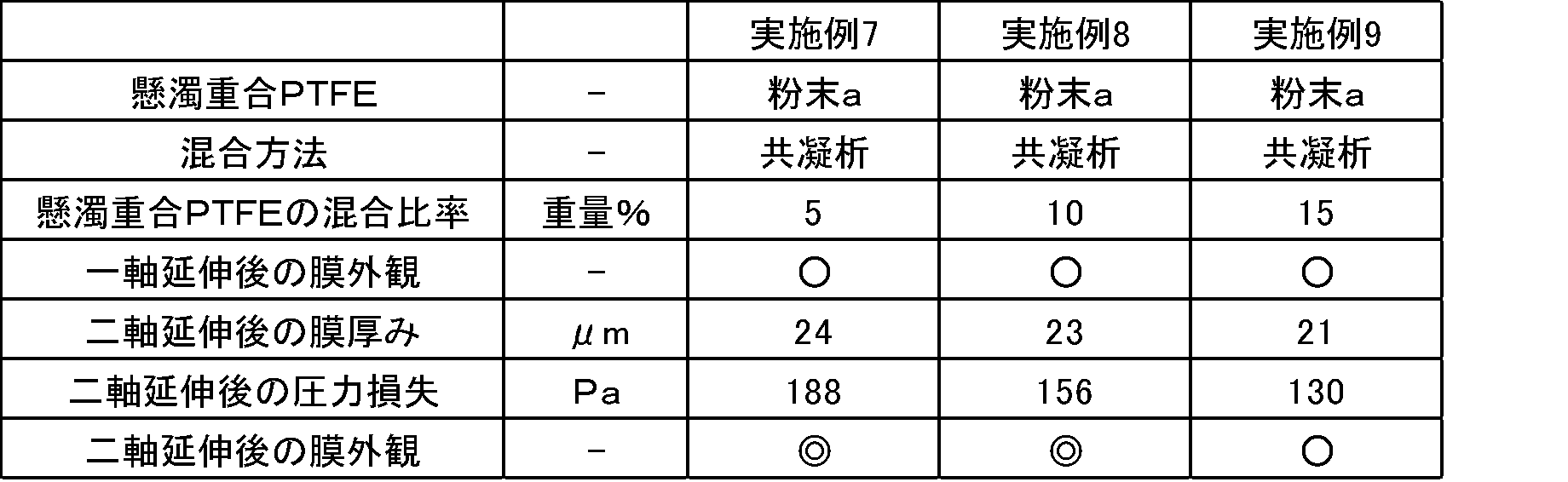
作製例1で得られたPTFEの水性分散液の仕込量を3036gと、作製例2で得られたPTFEの粉末aの仕込量を75gに変更する以外は実施例7と同様に共凝析を行い、PTFE混合物を得た。得られた混合物について、実施例1と同様に各種測定及び評価を行った。
本発明のPTFE混合物は、延伸材料として好適に利用できる材料であり、特に、PTFE多孔質膜を製造するための材料として好適なものである。
1:未焼成フィルムの巻き出しロール
2、18:巻き取りロール
3、4、5、8、9、10、11、12:ロール
6、7:ヒートロール
13:長手方向延伸フィルムの巻き出しロール
14:予熱ゾーン
15:延伸ゾーン
16:熱固定ゾーン
17:ラミネートロール
2、18:巻き取りロール
3、4、5、8、9、10、11、12:ロール
6、7:ヒートロール
13:長手方向延伸フィルムの巻き出しロール
14:予熱ゾーン
15:延伸ゾーン
16:熱固定ゾーン
17:ラミネートロール
Claims (10)
- テトラフルオロエチレンの乳化重合により得られた非溶融加工性を有するポリテトラフルオロエチレン(A)と、
テトラフルオロエチレンの懸濁重合により得られた非溶融加工性を有するポリテトラフルオロエチレン(B)と、
を含むことを特徴とするポリテトラフルオロエチレン混合物。 - ポリテトラフルオロエチレン(A)とポリテトラフルオロエチレン(B)との質量比(A)/(B)が99~50/1~50である請求項1記載のポリテトラフルオロエチレン混合物。
- ポリテトラフルオロエチレン(A)は、比表面積が6~20m2/gである請求項1又は2記載のポリテトラフルオロエチレン混合物。
- ポリテトラフルオロエチレン(B)は、比表面積が0.5~5.0m2/gである請求項1、2又は3記載のポリテトラフルオロエチレン混合物。
- ポリテトラフルオロエチレン(B)は、標準比重(SSG)が2.130~2.230である請求項1、2、3又は4記載のポリテトラフルオロエチレン混合物。
- ポリテトラフルオロエチレン(B)は、平均粒子径が1~1000μmである請求項1、2、3、4又は5記載のポリテトラフルオロエチレン混合物。
- ポリテトラフルオロエチレン(B)は、懸濁重合により得られたパウダーを造粒したものである請求項1、2、3、4、5又は6記載のポリテトラフルオロエチレン混合物。
- 延伸材料である請求項1、2、3、4、5、6又は7記載のポリテトラフルオロエチレン混合物。
- 二軸延伸材料である請求項1、2、3、4、5、6、7又は8記載のポリテトラフルオロエチレン混合物。
- 請求項1、2、3、4、5、6、7、8又は9記載のポリテトラフルオロエチレン混合物を延伸してなるポリテトラフルオロエチレン多孔質膜。
Priority Applications (1)
| Application Number | Priority Date | Filing Date | Title |
|---|---|---|---|
| CN201180061169.2A CN103261315B (zh) | 2010-12-21 | 2011-12-21 | 聚四氟乙烯混合物 |
Applications Claiming Priority (2)
| Application Number | Priority Date | Filing Date | Title |
|---|---|---|---|
| JP2010284988 | 2010-12-21 | ||
| JP2010-284988 | 2010-12-21 |
Publications (1)
| Publication Number | Publication Date |
|---|---|
| WO2012086721A1 true WO2012086721A1 (ja) | 2012-06-28 |
Family
ID=46313989
Family Applications (1)
| Application Number | Title | Priority Date | Filing Date |
|---|---|---|---|
| PCT/JP2011/079715 Ceased WO2012086721A1 (ja) | 2010-12-21 | 2011-12-21 | ポリテトラフルオロエチレン混合物 |
Country Status (3)
| Country | Link |
|---|---|
| JP (2) | JP5252067B2 (ja) |
| CN (1) | CN103261315B (ja) |
| WO (1) | WO2012086721A1 (ja) |
Cited By (2)
| Publication number | Priority date | Publication date | Assignee | Title |
|---|---|---|---|---|
| CN111873499A (zh) * | 2020-07-31 | 2020-11-03 | 德清华通新材料科技有限公司 | 一种防震楼梯板制作工艺 |
| CN118459910A (zh) * | 2024-07-11 | 2024-08-09 | 山东东岳高分子材料有限公司 | 一种高强度聚四氟乙烯再生粉复合料及其制备工艺 |
Families Citing this family (2)
| Publication number | Priority date | Publication date | Assignee | Title |
|---|---|---|---|---|
| CN107938007A (zh) * | 2018-01-03 | 2018-04-20 | 江苏金由新材料有限公司 | 采用不同分子量材料制备ptfe短纤维的系统及方法 |
| CN110982203B (zh) * | 2019-12-19 | 2021-11-12 | 施柏德(厦门)科技有限公司 | 一种ptfe多孔材料、制备方法及其制品与应用 |
Citations (2)
| Publication number | Priority date | Publication date | Assignee | Title |
|---|---|---|---|---|
| WO2005019320A1 (ja) * | 2003-08-25 | 2005-03-03 | Daikin Industries, Ltd. | 混合ポリテトラフルオロエチレン粉体及びポリテトラフルオロエチレン多孔成形体及びこれらの製造方法、ポリテトラフルオロエチレン多孔発泡成形体並びに高周波信号伝送用製品 |
| JP2011079879A (ja) * | 2009-10-02 | 2011-04-21 | Sumitomo Electric Fine Polymer Inc | ポリテトラフルオロエチレン多孔質体の製造方法 |
Family Cites Families (5)
| Publication number | Priority date | Publication date | Assignee | Title |
|---|---|---|---|---|
| JP3358828B2 (ja) * | 1991-07-04 | 2002-12-24 | 日本バルカー工業株式会社 | ポリテトラフルオロエチレン製多孔質膜およびその製造方法 |
| JPH09157472A (ja) * | 1995-12-01 | 1997-06-17 | Du Pont Mitsui Fluorochem Co Ltd | ポリテトラフルオロエチレン粉末組成物及びその製造方法 |
| GB9606818D0 (en) * | 1996-03-30 | 1996-06-05 | Gore W L & Ass Uk | Granular-type modified polytetrafluoroethlyene dispersions and fused articles prepared therefrom (Case A) |
| KR101231504B1 (ko) * | 2005-03-07 | 2013-02-07 | 아사히 가라스 가부시키가이샤 | 충전재가 들어간 폴리테트라플루오로에틸렌 조립물의 제조방법 |
| JP5073253B2 (ja) * | 2006-09-08 | 2012-11-14 | Ntn株式会社 | 樹脂摺動材 |
-
2011
- 2011-12-21 WO PCT/JP2011/079715 patent/WO2012086721A1/ja not_active Ceased
- 2011-12-21 CN CN201180061169.2A patent/CN103261315B/zh active Active
- 2011-12-21 JP JP2011279534A patent/JP5252067B2/ja active Active
-
2013
- 2013-02-13 JP JP2013025512A patent/JP5652484B2/ja active Active
Patent Citations (2)
| Publication number | Priority date | Publication date | Assignee | Title |
|---|---|---|---|---|
| WO2005019320A1 (ja) * | 2003-08-25 | 2005-03-03 | Daikin Industries, Ltd. | 混合ポリテトラフルオロエチレン粉体及びポリテトラフルオロエチレン多孔成形体及びこれらの製造方法、ポリテトラフルオロエチレン多孔発泡成形体並びに高周波信号伝送用製品 |
| JP2011079879A (ja) * | 2009-10-02 | 2011-04-21 | Sumitomo Electric Fine Polymer Inc | ポリテトラフルオロエチレン多孔質体の製造方法 |
Cited By (2)
| Publication number | Priority date | Publication date | Assignee | Title |
|---|---|---|---|---|
| CN111873499A (zh) * | 2020-07-31 | 2020-11-03 | 德清华通新材料科技有限公司 | 一种防震楼梯板制作工艺 |
| CN118459910A (zh) * | 2024-07-11 | 2024-08-09 | 山东东岳高分子材料有限公司 | 一种高强度聚四氟乙烯再生粉复合料及其制备工艺 |
Also Published As
| Publication number | Publication date |
|---|---|
| JP2013108090A (ja) | 2013-06-06 |
| CN103261315B (zh) | 2016-05-18 |
| JP2012144718A (ja) | 2012-08-02 |
| CN103261315A (zh) | 2013-08-21 |
| JP5252067B2 (ja) | 2013-07-31 |
| JP5652484B2 (ja) | 2015-01-14 |
Similar Documents
| Publication | Publication Date | Title |
|---|---|---|
| JP4984007B1 (ja) | ポリテトラフルオロエチレン混合物 | |
| JP5418584B2 (ja) | ポリテトラフルオロエチレン混合物 | |
| JP5444712B2 (ja) | テトラフルオロエチレン重合体及びその水性分散液 | |
| CN105793300B (zh) | 改性聚四氟乙烯细粉和单向拉伸多孔质体 | |
| JP6053559B2 (ja) | 延伸材料 | |
| WO2015080290A1 (ja) | 多孔質体、高分子電解質膜、フィルター用濾材及びフィルターユニット | |
| JP2010540749A (ja) | 延伸可能なtfeコポリマー、その生産方法及びその多孔性延伸物品 | |
| JP5652484B2 (ja) | ポリテトラフルオロエチレン混合物 | |
| CN112805082B (zh) | 具有尺寸稳定性的未烧结膨胀聚四氟乙烯复合膜 |
Legal Events
| Date | Code | Title | Description |
|---|---|---|---|
| 121 | Ep: the epo has been informed by wipo that ep was designated in this application |
Ref document number: 11849932 Country of ref document: EP Kind code of ref document: A1 |
|
| NENP | Non-entry into the national phase |
Ref country code: DE |
|
| 122 | Ep: pct application non-entry in european phase |
Ref document number: 11849932 Country of ref document: EP Kind code of ref document: A1 |