WO2012081557A1 - クリップ - Google Patents
クリップ Download PDFInfo
- Publication number
- WO2012081557A1 WO2012081557A1 PCT/JP2011/078724 JP2011078724W WO2012081557A1 WO 2012081557 A1 WO2012081557 A1 WO 2012081557A1 JP 2011078724 W JP2011078724 W JP 2011078724W WO 2012081557 A1 WO2012081557 A1 WO 2012081557A1
- Authority
- WO
- WIPO (PCT)
- Prior art keywords
- clip
- elastic
- panel
- female member
- elastic legs
- Prior art date
- Legal status (The legal status is an assumption and is not a legal conclusion. Google has not performed a legal analysis and makes no representation as to the accuracy of the status listed.)
- Ceased
Links
Images



Classifications
-
- B—PERFORMING OPERATIONS; TRANSPORTING
- B60—VEHICLES IN GENERAL
- B60N—SEATS SPECIALLY ADAPTED FOR VEHICLES; VEHICLE PASSENGER ACCOMMODATION NOT OTHERWISE PROVIDED FOR
- B60N3/00—Arrangements or adaptations of other passenger fittings, not otherwise provided for
- B60N3/02—Arrangements or adaptations of other passenger fittings, not otherwise provided for of hand grips or straps
- B60N3/023—Arrangements or adaptations of other passenger fittings, not otherwise provided for of hand grips or straps movable
-
- B—PERFORMING OPERATIONS; TRANSPORTING
- B60—VEHICLES IN GENERAL
- B60N—SEATS SPECIALLY ADAPTED FOR VEHICLES; VEHICLE PASSENGER ACCOMMODATION NOT OTHERWISE PROVIDED FOR
- B60N3/00—Arrangements or adaptations of other passenger fittings, not otherwise provided for
- B60N3/02—Arrangements or adaptations of other passenger fittings, not otherwise provided for of hand grips or straps
- B60N3/026—Arrangements or adaptations of other passenger fittings, not otherwise provided for of hand grips or straps characterised by the fixing means
-
- F—MECHANICAL ENGINEERING; LIGHTING; HEATING; WEAPONS; BLASTING
- F16—ENGINEERING ELEMENTS AND UNITS; GENERAL MEASURES FOR PRODUCING AND MAINTAINING EFFECTIVE FUNCTIONING OF MACHINES OR INSTALLATIONS; THERMAL INSULATION IN GENERAL
- F16B—DEVICES FOR FASTENING OR SECURING CONSTRUCTIONAL ELEMENTS OR MACHINE PARTS TOGETHER, e.g. NAILS, BOLTS, CIRCLIPS, CLAMPS, CLIPS OR WEDGES; JOINTS OR JOINTING
- F16B19/00—Bolts without screw-thread; Pins, including deformable elements; Rivets
- F16B19/04—Rivets; Spigots or the like fastened by riveting
- F16B19/08—Hollow rivets; Multi-part rivets
- F16B19/10—Hollow rivets; Multi-part rivets fastened by expanding mechanically
- F16B19/1027—Multi-part rivets
- F16B19/1036—Blind rivets
- F16B19/1081—Blind rivets fastened by a drive-pin
-
- F—MECHANICAL ENGINEERING; LIGHTING; HEATING; WEAPONS; BLASTING
- F16—ENGINEERING ELEMENTS AND UNITS; GENERAL MEASURES FOR PRODUCING AND MAINTAINING EFFECTIVE FUNCTIONING OF MACHINES OR INSTALLATIONS; THERMAL INSULATION IN GENERAL
- F16B—DEVICES FOR FASTENING OR SECURING CONSTRUCTIONAL ELEMENTS OR MACHINE PARTS TOGETHER, e.g. NAILS, BOLTS, CIRCLIPS, CLAMPS, CLIPS OR WEDGES; JOINTS OR JOINTING
- F16B21/00—Means for preventing relative axial movement of a pin, spigot, shaft or the like and a member surrounding it; Stud-and-socket releasable fastenings
- F16B21/06—Releasable fastening devices with snap-action
- F16B21/07—Releasable fastening devices with snap-action in which the socket has a resilient part
- F16B21/073—Releasable fastening devices with snap-action in which the socket has a resilient part the socket having a resilient part on its inside
-
- F—MECHANICAL ENGINEERING; LIGHTING; HEATING; WEAPONS; BLASTING
- F16—ENGINEERING ELEMENTS AND UNITS; GENERAL MEASURES FOR PRODUCING AND MAINTAINING EFFECTIVE FUNCTIONING OF MACHINES OR INSTALLATIONS; THERMAL INSULATION IN GENERAL
- F16B—DEVICES FOR FASTENING OR SECURING CONSTRUCTIONAL ELEMENTS OR MACHINE PARTS TOGETHER, e.g. NAILS, BOLTS, CIRCLIPS, CLAMPS, CLIPS OR WEDGES; JOINTS OR JOINTING
- F16B21/00—Means for preventing relative axial movement of a pin, spigot, shaft or the like and a member surrounding it; Stud-and-socket releasable fastenings
- F16B21/06—Releasable fastening devices with snap-action
- F16B21/08—Releasable fastening devices with snap-action in which the stud, pin, or spigot has a resilient part
- F16B21/086—Releasable fastening devices with snap-action in which the stud, pin, or spigot has a resilient part the shank of the stud, pin or spigot having elevations, ribs, fins or prongs intended for deformation or tilting predominantly in a direction perpendicular to the direction of insertion
-
- F—MECHANICAL ENGINEERING; LIGHTING; HEATING; WEAPONS; BLASTING
- F16—ENGINEERING ELEMENTS AND UNITS; GENERAL MEASURES FOR PRODUCING AND MAINTAINING EFFECTIVE FUNCTIONING OF MACHINES OR INSTALLATIONS; THERMAL INSULATION IN GENERAL
- F16B—DEVICES FOR FASTENING OR SECURING CONSTRUCTIONAL ELEMENTS OR MACHINE PARTS TOGETHER, e.g. NAILS, BOLTS, CIRCLIPS, CLAMPS, CLIPS OR WEDGES; JOINTS OR JOINTING
- F16B21/00—Means for preventing relative axial movement of a pin, spigot, shaft or the like and a member surrounding it; Stud-and-socket releasable fastenings
- F16B21/10—Means for preventing relative axial movement of a pin, spigot, shaft or the like and a member surrounding it; Stud-and-socket releasable fastenings by separate parts
- F16B21/12—Means for preventing relative axial movement of a pin, spigot, shaft or the like and a member surrounding it; Stud-and-socket releasable fastenings by separate parts with locking-pins or split-pins thrust into holes
Definitions
- the present invention relates to a clip suitable for article support that is detachably mounted in a mounting hole provided in a panel.
- FIGS. 8A and 8B show the clip structure disclosed in Patent Document 1.
- FIG. This structure particularly improves the operability of mounting on the panel, and includes a base member 11, a metal clip 21 assembled to the base member 11, and an engaging member that integrates the clip 21 with the base member 11. 31.
- the base member 11 projects along the back surface side of the base portion 12 with the flange portion 15 disposed along the panel 61 and the base portion 12 and is inserted into the mounting hole (locking hole) 61 a of the panel 61.
- the protrusion 13 the support wall 16 provided on the surface side of the base 12 and supporting the assist grip 41, and a pair of through holes penetrating the base 12.
- the clip 21 is substantially U-shaped, and is inserted into the base member 11 from the through hole and protrudes from the back side to the front side, and is engaged with the panel mounting hole 61a.
- the engaging member 31 includes an engaging portion 32 that is inserted into the through hole 23 a and prevents the clip 21 from coming off from the base member 11, a cover 33 that covers the front side of the base member, and a removal operation portion 35. .
- the base member 11 is engaged and fixed to the panel 61 by a pressing operation to the mounting hole 61a by the clip 21 integrated through the engaging member 31, and an installation tool or jig is required.
- the mounting operability is excellent.
- the cover 33 is the first on the clip side in that it is difficult to be destroyed even if it is subjected to an impact caused by an explosion of a vehicle airbag or a stepping stone from the road surface. There is also an advantage that the appearance can be maintained because the engaging portion 23 is covered.
- the engagement fixing force with respect to the panel-side mounting hole is proportional to the inclination angle of the elastic piece, which is the second engagement portion 24 that cuts and raises a part of the first engagement portion 23. If the engagement fixing force is increased by changing the inclination angle, the insertion force into the mounting hole becomes excessive and the mounting operability is impaired.
- the hook 21 is inserted into the panel side mounting hole 61a with the clip 21 mounted on the base member 11, and the hook-like elastic piece 24 is inserted and engaged therewith. Hard to add.
- the object of the present invention is to solve the problems as described above, and is excellent in mounting operability as in Patent Document 1, and in addition to the advantage that the engagement portion with respect to the panel is difficult to be destroyed by the metal cover, the mounting operability is impaired. It is intended to make it possible to reliably increase the engagement fixing force without making it possible, or to make it possible to temporarily fix the panel so as to improve the mounting procedure. Other purposes will be clarified in the description below.
- the present invention provides a clip that is detachably mounted in a mounting hole provided in a panel, and is provided on a flange portion disposed on the surface side of the panel and on a lower surface of the flange portion.
- a plurality of elastic legs inserted into the mounting hole so as to be temporarily fixed, a female member having an opening that penetrates the flange portion and communicates with a gap between the elastic legs, and an operation for covering the opening
- an insertion portion projecting from the lower surface of the operation portion and the elastic legs are deformed in a direction approaching each other in a state where the insertion portion is inserted and held in the gap from the opening. It is characterized by comprising a male member that can be blocked and a metal cover that covers a part of the elastic leg in an attached state fitted to the female member.
- the present invention is embodied as follows.
- (A) The elastic leg and the metal cover are fitted in a state in which the elastic legs can be deformed in a direction approaching each other by a convex portion provided on one side and a concave portion provided on the other side. It is the structure which is done.
- the metal cover is elasticated in advance. It can be handled in a state where it is attached to the leg, thereby improving handling and mounting operability to the panel.
- the female member press-holds the male member while the insertion portion is inserted into the gap between the elastic legs from the opening, and the elastic member is pressed against the panel in the press-contact holding state.
- a leg is inserted into the mounting hole and engaged to be temporarily fixed, and the insertion portion is further inserted and finally fixed to the elastic leg by pressing.
- a plurality of clips can be temporarily fixed to the panel, and these can be permanently fixed at the same time. From this point, the mounting work procedure can be improved, and the mounting operability to the panel is further improved. it can.
- the metal cover includes a covering portion that covers a tip and an outer surface portion of each elastic leg, and a folded piece portion that extends from a part of the covering portion and contacts the flange portion. It is a configuration. In this case, the tip and the outer surface of each elastic leg are covered and protected by the cover part of the cover, and the deformed part is brought into contact with the flange part on the female member side and deformed even if a stepping stone hits the cover part. By making it difficult to do so, the protective function of the metal cover can be fully exhibited.
- the metal cover is configured to maintain a buffer space between the elastic leg and the tip of the elastic leg in an attached state fitted to the female member.
- At least one of the female member and the male member is provided with a jig insertion space for inserting a jig for releasing the holding state of the male member with respect to the female member.
- a screwdriver or the like is inserted into the jig insertion space and the male member is forcibly pulled out of the female member so that the clip can be easily disassembled.
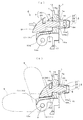
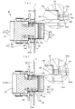
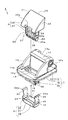
- the clip of the form of 1 form of this invention is shown temporarily in the attachment hole of the panel, (a) is a side view, (b) is the figure seen from the lower surface side of the panel. (A) And (b) is sectional drawing which showed the state which temporarily fastened the said clip to the attachment hole of the panel, and the state fastened finally along the AA line of said FIG.1 (b). (A) And (b) is sectional drawing which showed the state which temporarily fastened the said clip to the attachment hole of the panel, and the state fastened finally along the BB line of the said FIG. 1 (a). It is a disassembled perspective view which shows the structure of the said clip.
- (A) And (b) is the schematic perspective view shown by the temporary fix
- the female member single item in the said embodiment of this invention is shown, (a) is a top view, (b) is a side view, (c) is a front view.
- the male member single item in the said embodiment of this invention is shown, (a) is a side view, (b) is a front view, (c) is a bottom view.
- the structure of patent document 1 is shown, (a) is sectional drawing of a clip, (b) is a side view in the use condition with which the panel was mounted
- the clip 4 of the embodiment is detachably mounted in a rectangular mounting hole 7a provided in the panel 7 as shown in FIGS. 2 (a) and 2 (b) and FIG. It is supported in a movable manner, and has a three-point configuration including a female member 1 and a male member 2 made of resin and a cover 3 made of metal. Each member has the following schematic configuration.
- the female member 1 includes a flange portion 10 disposed on the surface side of the panel 7, a support wall portion 11 that protrudes from the upper surface of the flange portion 10 and supports the assist grip 5 via the pivot 6, and a flange portion A plurality of (in this example, two) elastic legs 15 projecting from the lower surface of 10 and inserted into the mounting hole 7a so as to be temporarily fixed, and a gap S between the elastic legs 15 penetrating the flange portion 10. And an opening 14 communicating therewith.
- the male member 2 has an operation portion 20 that covers the opening 14 and an insertion portion 25 that projects from the lower surface of the operation portion 20, and the insertion portion 25 is inserted and held in the gap S from the opening 14.
- the elastic legs 15 can be prevented from being deformed in the direction in which they approach each other.
- the cover 3 includes covering portions 30 to 32 that cover the distal end portions of the respective elastic legs 15, and a folded piece portion 33 that extends from a portion of the covering portion 32 and contacts the flange portion 10.
- the flange portion 10 has a substantially rectangular plate shape.
- the opening 14 is inside the support wall portion 11 and penetrates the front and back sides, the slit 14a is between each side wall 12 and penetrates the front and back sides, and the slits 14a and 14 are opened.
- a thin elastic piece 10a is formed with a thin elastic piece 10a.
- a pedestal 19 and an abutting portion 19 a protruding from the front and rear portions of the pedestal 19 are provided on the back surface of the flange portion 10.
- the abutting portion 19a is in contact with the surface of the panel 7 with the female member 1 engaged and fixed to the panel 7 as shown in FIG.
- the interior material may be attached to the panel 7 as in Patent Document 1.
- the pedestal 19 is arranged along the interior material, and the contact portion 19a is brought into contact with the panel 7 through a hole provided in the interior material.
- the heel support wall portion 11 is substantially U-shaped by the side walls 12 and the intermediate wall 13 connecting the side walls 12 to each other.
- Each side wall 12 has an upper portion displaced further to the opposite side of the opening 14 than the intermediate wall 13, and has a shaft hole 12a provided on the coaxial line at the displaced position.
- the assist grip 5 is pivotally supported with respect to the two clips 4 engaged and fixed to the panel 7 via pivots 6 inserted into the respective shaft holes 12a (this support structure).
- Each elastic leg 15 protrude from the lateral edge of the opening 14 so as to face each other.
- Each elastic leg 15 has a substantially rectangular plate shape, and is formed such that the gap S between the legs is narrower on the protruding end side than on the base end side.
- Each elastic leg 15 includes a protruding portion 15a that protrudes one step inside the distal end, an engaging portion 15b that is an upper step of an inclined surface that is provided on the outer surface and gradually protrudes from the distal end toward the proximal end, And claw portions 16 provided on both side surfaces on the distal end side.
- Each overhanging part 15a is a part which contacts the insertion part 25 of a male member.
- the engaging portion 15b is a portion that is elastically engaged with the edge of the mounting hole 7a.
- the claw portion 16 is a place to be fitted to the cover 3.
- the female member 1 is inserted into the panel mounting hole 7a while reducing the diameter while the male member 2 is pressed and held as shown in FIG. 2A.
- the engaging portion 15b is engaged to be in a temporarily fixed state.
- the female member 1 is further pushed from the temporarily fixed state as shown in FIG. 2B and the insertion portion 25 is press-fitted between the elastic legs 15 from the temporarily fixed state, the elastic legs 15 are connected to each other. It is switched to the final stop state where it cannot be deformed in the direction of diameter reduction.
- the operation portion 20 corresponds to the head of the insertion portion 25, is partitioned by the upper curved operation surface 21, both side surfaces 22, the lower surface 23, and the back surface 24, and is large enough to fit within the U shape of the support wall portion 11. It has become.
- the operation surface 21 and the lower surface 23 are provided with a space 20a for inserting a jig. That is, the space 20a is a place where a tool 9 such as a screwdriver for releasing the holding state of the male member 2 with respect to the female member 1 is inserted as shown in FIG.
- the scissors insertion portion 25 is formed in a substantially rectangular plate shape, and the tip 25a is slightly thinned.
- the insertion portion 25 includes slits 26 and 26 provided on the inner side of both side surfaces and extending in parallel with the side surfaces, a total of four concave portions 27 provided between the slits on the front and rear surfaces, It has a convex portion 28 on the front end side and a protruding portion 29 on the base end side provided on the surface.
- Each slit 26 makes the convex part 28 and the overhang
- the concave portion 27 is intended for lacking thickness, that is, for weight reduction, but may be omitted. Between the convex part 28 and the overhang
- the cover 3 is a breath product, and includes a bottom surface side covering portion 30 that covers the front end surface side of each elastic leg 15, a front and back surface side covering portion 31 that covers the front end side outer surface of each elastic leg 15, and the front end of each elastic leg 15. It has the both end side coating
- each claw portion 16 on the elastic leg side corresponds.
- the cover 3 is temporarily assembled to the female member 1 by fitting with the recess 34.
- the two claw portions 16 of the elastic leg 15 can be loosely fitted in the rectangular hole which is the concave portion 34, that is, can be deformed in a direction approaching or separating from each other.
- the clip 4 temporarily assembled as described above is temporarily fixed to the panel 7 by a one-touch operation as shown in FIGS. 2 and 3, and as shown in each (b).
- the temporary stop state can be switched to the final stop state by a one-touch operation. That is, the temporarily assembled clip 4 passes through the mounting hole 7a while being displaced in the direction in which the elastic legs 15 of the female member approach each other with respect to the panel 7, and is restored when completely passed.
- the engagement portion 15b is engaged or locked with the hole edge of the attachment hole 7a and temporarily fixed.
- the lower surface 23 contacts the flange portion 10 as shown in FIG. It is moved in the same direction until the final stage and switched to the final stop state.
- the distal end portion 25a of the insertion portion 25 is press-fitted between the overhanging portions 15a while displacing the opposing inner surfaces of the overhanging portions 15a in the expanding direction, and is provided on each elastic leg.
- the claw portions 16 are also closely fitted to both sides of the rectangular hole of the recessed portion 34 with the mutual space widened.
- the elastic legs 15 are prevented from being displaced toward each other, whereby the engagement of the engagement portion 15b with the attachment hole 7a is reliably maintained, and the engagement fixing force can be increased.
- the cover 3 covers and protects at least the distal ends of both elastic legs 15, and keeps a buffer space 8 between the elastic legs 15 as shown in FIG. For this reason, in this structure, even if a stepping stone or the like hits the covering portions 30 to 32 in the used state, the shock can be relaxed and absorbed by the buffering action of the buffer space 8.
- the above clip 4 can be easily recovered from the state of being permanently fixed to the mounting hole 7a of the panel. That is, the operator uses the tool 9 such as a screwdriver as shown in FIG. 5B to insert the tip of the tool 9 into the space 20a from the direction of the circled number 1 and lift it upward in the circled number 2. Then, the male member 2 is pulled out by a predetermined amount against the female member 1 against the pressure holding force between the protruding portion 29 and the elastic piece 10a, and the concave portion 25b and the elastic piece 10a as shown in FIG. Are engaged, that is, temporarily assembled. For this reason, when the clip 4 (the female member 1) is pulled away from the panel 7, each engagement portion 15b is disengaged from the attachment hole 7a with deformation to the inside of both elastic legs 15. It can be easily pulled out from the mounting hole 7a.
- the tool 9 such as a screwdriver as shown in FIG. 5B
- the clip of this invention should just be equipped with the structure specified by a claim,
- the detail can be changed and developed with reference to the form example.
- an article or member other than the assist grip may be attached to the support wall portion of the female member, or the cover portion shape of the cover may be changed.
- the entire contents of the specification, claims, drawings and abstract of Japanese Patent Application No. 2010-277650 filed on Dec. 14, 2010 are incorporated herein by reference as the disclosure of the specification of the present invention. Is.
Landscapes
- Engineering & Computer Science (AREA)
- General Engineering & Computer Science (AREA)
- Mechanical Engineering (AREA)
- Transportation (AREA)
- Insertion Pins And Rivets (AREA)
- Passenger Equipment (AREA)
Abstract
パネルの取付孔に着脱可能に装着されるクリップとして、パネルの表面側に配置されるフランジ部、及びフランジ部の下面に突設されて取付孔に仮止め可能に挿通される複数の弾性脚、並びにフランジ部を貫通して弾性脚同士の間の隙間に連通している開口を有した雌部材と、開口を覆う操作部、及び操作部の下面に突設された差込部を有し、差込部が開口から隙間に挿入保持された状態で各弾性脚が互いに接近する方向への変形を阻止可能にする雄部材と、雌部材に嵌合された取付状態で弾性脚の一部を覆う金属製カバーとからなることを特徴としている。
Description
本発明は、パネルに設けられた取付孔に着脱可能に装着される物品支持用として好適なクリップに関する。
図8(a)(b)は特許文献1に開示のクリップ構造を示している。この構造は、特にパネルへの取付操作性を良好にしたものであり、ベース部材11と、ベース部材11に組み付けられる金属製のクリップ21と、ベース部材11にクリップ21を一体化する係合部材31とからなる。
ここで、ベース部材11は、パネル61に沿って配置される鍔部15付きのベース部12、ベース部12の裏面側に突出されてパネル61の取付孔(係止孔)61aに挿入される突出部13、ベース部12の表面側に設けられてアシストグリップ41を支持する支持壁部16、ベース部12を貫通している対の貫通孔とを有している。クリップ21は、概略U形状からなり、ベース部材11に対し前記貫通孔から挿通されて裏側より表側へ突出される第1係合部23,23、パネルの取付孔61aに係合される第2係合部24、各第1係合部23のベース部材表側へ突出した部分に設けられ、挿入方向と直交する方向の貫通孔23a、ベース部材の突出部13を挿入する基部側の貫通孔とを有している。係合部材31は、貫通孔23aへ挿入されてベース部材11に対するクリップ21の抜けを阻止する係合部32、及びベース部材の表側を覆うカバー33、並びに取り外し操作部35とを有している。
上記特許文献1の構造では、ベース部材11が係合部材31を介して一体化したクリップ21によりパネル61に対し取付孔61aへの押し操作によって係合固定され、取付工具や治具を必要としないため取付操作性に優れている。また、金属製のクリップを使用しているため用途例として車両のエアバックの爆発に起因した衝撃や路面側からの飛び石などによる衝撃を受けても破壊され難い点、カバー33がクリップ側第1係合部23を覆うため見栄えを維持できる点などの利点もある。
しかし、この構造では、まず、パネル側取付孔に対する係合固定力は、第1係合部23の一部を切り起こした第2係合部24である弾性片の傾斜角度などに比例するため、傾斜角度を変えて係合固定力を大きくすると、取付孔への挿入力も過大となり取付操作性が損なわれる。また、クリップ21がベース部材11に装着された状態でパネル側取付孔61aに第2係合部24である錨状の弾性片を挿入して係合するため、パネルに対し仮止めする構成を追加し難い。
本発明の目的は、以上のような課題を解消して、特許文献1と同じく取付操作性に優れ、金属製カバーによりパネルに対する係合箇所を破壊され難いという利点に加え、取付操作性を損なうことなく係合固定力を確実に増大できるようにしたり、パネルに対し仮止め可能にして取付手順などを改善し易くすることにある。他の目的は以下の内容説明のなかで明らかにする。
上記目的を達成するため本発明は、パネルに設けられた取付孔に着脱可能に装着されるクリップにおいて、前記パネルの表面側に配置されるフランジ部、及び前記フランジ部の下面に突設されて前記取付孔に仮止め可能に挿通される複数の弾性脚、並びに前記フランジ部を貫通して前記弾性脚同士の間の隙間に連通している開口を有した雌部材と、前記開口を覆う操作部、及び前記操作部の下面に突設された差込部を有し、前記差込部が前記開口から前記隙間に挿入保持された状態で前記各弾性脚の互いに接近する方向への変形を阻止可能にする雄部材と、前記雌部材に嵌合された取付状態で前記弾性脚の一部を覆う金属製カバーとからなることを特徴としている。
本発明は、次のように具体化されることがより好ましい。
(ア)、前記弾性脚と前記金属製カバーとは、どちらか一方に設けた凸部と、他方に設けた凹部とにより、前記各弾性脚が互いに接近する方向に変形可能な状態で嵌合されている構成である。この場合、雌部材側の弾性脚と金属製カバーとが凸部と凹部とを介して各弾性脚を互いに接近する方向に変形可能な状態で嵌合されているため、金属製カバーを予め弾性脚に取り付けた状態で取り扱うことができ、それにより取扱性やパネルへの取付操作性をより向上できる。
(イ)、前記雌部材は前記差込部が前記開口から前記弾性脚同士の隙間に挿入される途中で前記雄部材を圧接保持し、その圧接保持状態で、前記パネルに対して、前記弾性脚を前記取付孔に挿入し係合することにより仮止めされ、前記差込部が更に挿入されて前記弾性脚に圧接することにより本止めされる構成である。この場合、例えば、パネルに対して複数のクリップを仮止めし、それらを同時に本止め操作することができ、その点から取付作業手順を改善でき、引いてはパネルへの取付操作性も更に向上できる。
(ア)、前記弾性脚と前記金属製カバーとは、どちらか一方に設けた凸部と、他方に設けた凹部とにより、前記各弾性脚が互いに接近する方向に変形可能な状態で嵌合されている構成である。この場合、雌部材側の弾性脚と金属製カバーとが凸部と凹部とを介して各弾性脚を互いに接近する方向に変形可能な状態で嵌合されているため、金属製カバーを予め弾性脚に取り付けた状態で取り扱うことができ、それにより取扱性やパネルへの取付操作性をより向上できる。
(イ)、前記雌部材は前記差込部が前記開口から前記弾性脚同士の隙間に挿入される途中で前記雄部材を圧接保持し、その圧接保持状態で、前記パネルに対して、前記弾性脚を前記取付孔に挿入し係合することにより仮止めされ、前記差込部が更に挿入されて前記弾性脚に圧接することにより本止めされる構成である。この場合、例えば、パネルに対して複数のクリップを仮止めし、それらを同時に本止め操作することができ、その点から取付作業手順を改善でき、引いてはパネルへの取付操作性も更に向上できる。
(ウ)、前記金属製カバーは、前記各弾性脚の先端及び外面部分を覆う被覆部、及び前記被覆部の一部から延設されて前記フランジ部に当接する折返し片部を有している構成である。この場合、各弾性脚の先端及び外面部分をカバーの被覆部により覆って保護することにより、かつ、雌部材側のフランジ部に折返し片部を当接して被覆部に飛び石などが当たっても変形し難くすることにより、金属製カバーの保護機能を充分に発揮できるようにする。
(エ)、前記金属製カバーは、前記雌部材に嵌合された取付状態で前記弾性脚の先端との間に緩衝用空間を保つよう形成されている構成である。この場合、例えば被覆部に飛び石などが当たったときにその空間の緩衝作用により衝撃を緩和吸収できるようにする。
(オ)、前記雌部材及び前記雄部材の少なくとも一方には前記雄部材の前記雌部材に対する保持状態を解除する治具を挿入する治具差込用空間が設けられている構成である。この場合、例えば、クリップの解体時にドライバーなどを冶具差込用空間に差し込んで雄部材を雌部材から強制的に引き抜いてクリップの解体操作を容易に行えるようにする。
(エ)、前記金属製カバーは、前記雌部材に嵌合された取付状態で前記弾性脚の先端との間に緩衝用空間を保つよう形成されている構成である。この場合、例えば被覆部に飛び石などが当たったときにその空間の緩衝作用により衝撃を緩和吸収できるようにする。
(オ)、前記雌部材及び前記雄部材の少なくとも一方には前記雄部材の前記雌部材に対する保持状態を解除する治具を挿入する治具差込用空間が設けられている構成である。この場合、例えば、クリップの解体時にドライバーなどを冶具差込用空間に差し込んで雄部材を雌部材から強制的に引き抜いてクリップの解体操作を容易に行えるようにする。
本発明では、雌部材が雄部材を開口に挿入した状態で、パネルに対して弾性脚を取付孔に挿入し係合した後、その係合状態で、雄部材が押し込み操作されると、差込部が弾性脚同士の間の隙間に挿入保持されると、各弾性脚が互いに接近する方向への変形を阻止され、それにより解除不能に係合固定される。このため、この構造では、特許文献1と同様に取付操作性に優れ、金属製カバーにより弾性脚などを破壊され難くできる利点に加え、取付操作性を損なうことなく係合固定力を確実に増大できる。
以下、本発明の形態例について添付図面を参照しながら説明する。この説明では、クリップの構造、組立、パネルへの取付操作の順で詳述する。
(構造)形態例のクリップ4は、図2(a)(b)及び図4に示されるごとくパネル7に設けられた矩形状の取付孔7aに着脱可能に装着されてアシストグリップ5などを回動可能に支持するものであり、樹脂製の雌部材1及び雄部材2並びに金属製のカバー3の3点構成である。各部材は次のような概略構成からなる。すなわち、雌部材1は、パネル7の表面側に配置されるフランジ部10と、フランジ部10の上面に突設されてアシストグリップ5を枢軸6を介して支持する支持壁部11と、フランジ部10の下面に突設されて取付孔7aに仮止め可能に挿通される複数(この例では2つ)の弾性脚15と、フランジ部10を貫通して弾性脚15同士の間の隙間Sに連通している開口14とを有している。雄部材2は、開口14を覆う操作部20と、操作部20の下面に突設された差込部25とを有し、差込部25が開口14から隙間Sに挿入保持された状態で各弾性脚15の互いに接近する方向への変形を阻止可能にする。カバー3は、各弾性脚15の先端部を覆う被覆部30~32と、被覆部32の一部から延設されてフランジ部10に当接する折返し片部33とを有している。以下、各部材の細部を明らかにする。
まず、雌部材1を図4及び図6(a)~(c)を参照して説明する。フランジ部10は、略矩形板状をなし、支持壁部11の内側にあって表裏を貫通した開口14と、各側壁12との間にあって表裏を貫通したスリット14aと、各スリット14aと開口14との間を構成している細い弾性片10aとを形成している。また、フランジ部10の裏面には、台座19及び台座19の前後部に突設した突当部19aが設けられている。そして、この例では、雌部材1を図2(b)のごとくパネル7に係合固定した状態で、突当部19aがパネル7の表面に当接されている。但し、パネル7には特許文献1のごとく内装材が添設されることがある。その場合は、例えば、台座19がその内装材に沿って配置され、当接部19aがその内装材に設けられた穴からパネル7に当接される。
支持壁部11は、両側壁12及び両側壁12同士を接続している中間壁13により概略コ形状となっている。各両側壁12は、上部が中間壁13よりも更に開口14と反対側へ変位されており、その変位した箇所に同軸線上に設けられた軸孔12aを有している。そして、この例では、パネル7に係合固定される2つのクリップ4に対し、アシストグリップ5が各軸孔12aに挿通される枢軸6を介して回動可能に枢支される(この支持構造は特許文献1や特開2002-225613号公報などを参照)。
2つの弾性脚15は、開口14の横縁部からそれぞれ対向した状態で突出されている。各弾性脚15は、略矩形板状となっていて、脚同士の間の隙間Sが基端側より突出端側の方を狭くなるよう形成されている。また、各弾性脚15は、先端の内側に一段出っ張った張出部15aと、外面に設けられて先端から基端手前に向かって次第に張り出す傾斜面の上段差である係合部15bと、先端側の両側面に設けられた爪部16とを有している。各張出部15aは雄部材の差込部25と当接する箇所である。係合部15bは、取付孔7aの縁に弾性係合される箇所である。爪部16はカバー3に嵌合される箇所である。
そして、以上の雌部材1は、図2(a)のごとく雄部材2を圧接保持した状態で、各弾性脚15がパネルの取付孔7aに対して、縮径しつつ挿通され、挿通と同時に元の形状に復元されことにより係合部15bが係合して仮止め状態となる。雌部材1は、仮止め状態から、雄部材2が図2(b)のごとく更に押し操作されて、差込部25が弾性脚15同士の間に圧入されると、各弾性脚15同士が縮径方向に変形不能となる本止め状態に切り換えられる。
次に、雄部材2を図4及び図7(a)~(c)を参照して説明する。操作部20は、差込部25の頭部に相当し、上側の湾曲状操作面21、両側面22、下面23、背面24により区画形成され、前記支持壁部11のコ形内に収まる大きさとなっている。操作面21及び下面23には治具差込用の空間20aが設けられている。つまり、この空間20aは、図5(b)のごとく雌部材1に対する雄部材2の保持状態を解除するためのドライバー等の工具9を挿入する箇所である。
差込部25は、概略矩形板状からなるとともに、先端25aが少し薄くなっている。また、差込部25は、両側面の内側に設けられて側面と平行に延びているスリット26,26と、前後面にあって両スリット間に設けられている合計4つの凹部27と、両側面に設けられた先端側の凸部28及び基端側の張出部29とを有している。各スリット26は、対応側面の凸部28及び張出部29を弾性変形可能にしている。凹部27は、欠肉用つまり軽量化を目的としたものであるが、省略されることもある。凸部28と張出部29との間は仮組み付け用の凹部25bに設定されている。
次に、カバー3を図3(a)(b)及び図4を参照して説明する。カバー3は、ブレス品であり、各弾性脚15の先端面側を覆う底面側被覆部30と、各弾性脚15の先端側外面を覆う前後面側被覆部31と、各弾性脚15の先端側側面を覆う両端側被覆部32と、両端面側被覆部32を上向きに延長した折返し片部33とを有している。また、両端側被覆部32には矩形孔である凹部34がそれぞれ設けられている。各折返し片部33の先端33aは外側に屈曲形成されている。
(組立)以上の各部材は、以下に例示するような手順により、図5(a)の仮組み付け状態に組み付けられて一体物のクリップ4として取り扱われる。この組立では、雌部材1に対してカバー3と雄部材2とが共に仮組み付けされる。ここでは、雌部材1に対してカバー3を組み付けた後に雄部材2を組み付ける例で述べるが、雌部材1に対して雄部材2を組み付けた後、カバー3を後で組み付けるようにしてもよい。
前者の作業では、被覆部30~32の内側に両弾性脚15を収容し、かつ、各折返し片部の先端33aをフランジ部10に当接すると、弾性脚側の各爪部16が対応する凹部34と嵌合し、それによりカバー3が雌部材1に対し仮組み付けされる。この状態では、弾性脚15の2つの爪部16は、凹部34である矩形孔内で遊嵌、つまり互いに接近したり離間する方向に変形可能となっている。
後者の作業では、雄部材の差込部25を開口14から隙間Sに挿入すると、図3(a)の拡大図に示したごとく弾性片10aが凸部28を弾性的に乗り越えて凹部25bに係合する。それにより、雄部材2は雌部材1に対して弾性片10aと凹部25bとが解除可能に係合された状態で仮組み付けされ、一体物として取り扱うことができる。
(パネルへの取付操作)以上のようにして仮組み付けされたクリップ4は、図2及び図3の各(a)ごとくパネル7に対してワンタッチ操作により仮止めされ、かつ各(b)のごとくワンタッチ操作により仮止め状態から本止めに切り換えられる。すなわち、上記仮組み付けされたクリップ4は、雌部材の各弾性脚15がパネル7に対して、互いに接近する方向に変位しながら取付孔7aを通過し、完全に通過されると復元されて、係合部15bが取付孔7aの孔縁に係合ないしは係止されて仮止めされる。
また、作業者は、以上の仮止め状態から、雄部材の操作部20を図2(a)の矢印方向へ押すと、差込部25が同(b)のごとく下面23がフランジ部10に当たる最終段階まで同方向へ移動されて本止め状態に切り換えられる。本止め状態では、差込部25の先端部25aが両張出部15aの対向内面を拡開方向に変位しながら張出部15a同士の間に圧入され、かつ、各弾性脚に設けられた爪部16も互いの間隔を拡げられて凹部34の矩形孔の両側に強く嵌合されている。このため、この構造では、両弾性脚15が互いに接近する方向への変位を阻止され、それにより取付孔7aに対する係合部15bの係合が確実に維持され、係合固定力を増大できる。また、カバー3は、両弾性脚15の少なくとも先端側を覆って保護し、かつ図2(b)のごとく弾性脚15の先端との間に緩衝用空間8を保っている。このため、この構造では、使用状態において、例えば被覆部30~32に飛び石などが当たっても、緩衝用空間8の緩衝作用により衝撃を緩和吸収できる。
また、以上のクリップ4は、パネルの取付孔7aに本止めされた状態から簡単に回収できる。すなわち、作業者は、図5(b)のごとくドライバーなどの工具9を用いて、工具9の先端を空間20aに丸数字1の方向から差し込んで、丸数字2の上方向に持ち上げる。すると、雄部材2は、雌部材1に対して張出部29と弾性片10aとの圧接保持力に抗して所定量だけ引き抜かれるとともに、図3(a)のごとく凹部25bと弾性片10aとが係合、つまり仮組み付け状態となる。このため、クリップ4(の雌部材1)は、パネル7から離れる方向に引っ張ると、各係合部15bが両弾性脚15の内側への変形を伴って取付孔7aから係合解除されるため、取付孔7aから簡単に引き抜かれる。
なお、本発明のクリップは、請求項で特定される構成を備えておればよく、細部は形態例を参考にして変更したり展開可能なものである。その例としては、雌部材の支持壁部にはアシストグリップ以外の物品や部材を取り付けたり、カバーの被覆部形状を変更することである。
2010年12月14日に出願された日本特許出願第2010-277650号の明細書、特許請求の範囲、図面及び要約書の全内容をここに引用し、本発明の明細書の開示として、取り入れるものである。
2010年12月14日に出願された日本特許出願第2010-277650号の明細書、特許請求の範囲、図面及び要約書の全内容をここに引用し、本発明の明細書の開示として、取り入れるものである。
Claims (6)
- パネルに設けられた取付孔に着脱可能に装着されるクリップにおいて、
前記パネルの表面側に配置されるフランジ部、及び前記フランジ部の下面に突設されて前記取付孔に仮止め可能に挿通される複数の弾性脚、並びに前記フランジ部を貫通して前記弾性脚同士の間の隙間に連通している開口を有した雌部材と
前記開口を覆う大きさの操作部、及び前記操作部の下面に突設された差込部を有し、前記差込部が前記開口から前記隙間に挿入保持された状態で前記各弾性脚が互いに接近する方向への変形を阻止可能にする雄部材と、
前記雌部材に嵌合された取付状態で前記弾性脚の一部を覆う金属製カバーとからなることを特徴とするクリップ。 - 前記弾性脚と前記金属製カバーとは、どちらか一方に設けた凸部と、他方に設けた凹部とにより、前記各弾性脚が互いに接近する方向に変形可能な状態で嵌合されていることを特徴とする請求項1に記載のクリップ。
- 前記雌部材は、前記差込部が前記開口から前記弾性脚同士の隙間に挿入される途中で前記雄部材を圧接保持し、その圧接保持状態で、前記パネルに対して、前記弾性脚を前記取付孔に挿入し係合することにより仮止めされ、前記差込部が更に挿入されて前記弾性脚に圧接することにより本止めされることを特徴とする請求項1又は2に記載のクリップ。
- 前記金属製カバーは、前記各弾性脚の先端及び外面部分を覆う被覆部、及び前記被覆部の一部から延設されて前記フランジ部に当接する折返し片部を有していることを特徴とする請求項1から3の何れかに記載のクリップ。
- 前記金属製カバーは、前記雌部材に嵌合された取付状態で前記弾性脚の先端との間に緩衝用空間を保つよう形成されていることを特徴とする請求項1から4の何れかに記載のクリップ。
- 前記雌部材及び前記雄部材の少なくとも一方には前記雄部材の前記雌部材に対する保持状態を解除する治具を挿入する治具差込用空間が設けられていることを特徴とする請求項1から5の何れかに記載のクリップ。
Applications Claiming Priority (2)
| Application Number | Priority Date | Filing Date | Title |
|---|---|---|---|
| JP2010277650A JP5620803B2 (ja) | 2010-12-14 | 2010-12-14 | クリップ |
| JP2010-277650 | 2010-12-14 |
Publications (1)
| Publication Number | Publication Date |
|---|---|
| WO2012081557A1 true WO2012081557A1 (ja) | 2012-06-21 |
Family
ID=46244656
Family Applications (1)
| Application Number | Title | Priority Date | Filing Date |
|---|---|---|---|
| PCT/JP2011/078724 Ceased WO2012081557A1 (ja) | 2010-12-14 | 2011-12-12 | クリップ |
Country Status (2)
| Country | Link |
|---|---|
| JP (1) | JP5620803B2 (ja) |
| WO (1) | WO2012081557A1 (ja) |
Families Citing this family (1)
| Publication number | Priority date | Publication date | Assignee | Title |
|---|---|---|---|---|
| JP7165544B2 (ja) * | 2018-09-21 | 2022-11-04 | 株式会社イノアックコーポレーション | 車両内装部材の取付装置 |
Citations (3)
| Publication number | Priority date | Publication date | Assignee | Title |
|---|---|---|---|---|
| JPH0280209U (ja) * | 1988-12-10 | 1990-06-20 | ||
| JP2007278375A (ja) * | 2006-04-05 | 2007-10-25 | Togo Seisakusho Corp | クリップ |
| JP2009120118A (ja) * | 2007-11-16 | 2009-06-04 | Toyoda Gosei Co Ltd | 部品の取付構造及び部品の取付方法 |
-
2010
- 2010-12-14 JP JP2010277650A patent/JP5620803B2/ja not_active Expired - Fee Related
-
2011
- 2011-12-12 WO PCT/JP2011/078724 patent/WO2012081557A1/ja not_active Ceased
Patent Citations (3)
| Publication number | Priority date | Publication date | Assignee | Title |
|---|---|---|---|---|
| JPH0280209U (ja) * | 1988-12-10 | 1990-06-20 | ||
| JP2007278375A (ja) * | 2006-04-05 | 2007-10-25 | Togo Seisakusho Corp | クリップ |
| JP2009120118A (ja) * | 2007-11-16 | 2009-06-04 | Toyoda Gosei Co Ltd | 部品の取付構造及び部品の取付方法 |
Also Published As
| Publication number | Publication date |
|---|---|
| JP5620803B2 (ja) | 2014-11-05 |
| JP2012127379A (ja) | 2012-07-05 |
Similar Documents
| Publication | Publication Date | Title |
|---|---|---|
| EP1630426B1 (en) | Double clip fastener device with retaining plate | |
| US8038167B2 (en) | Two stage high retention fastener | |
| JP5048263B2 (ja) | Wベース型留具 | |
| JP2006207607A (ja) | クリップ | |
| JP2006151047A (ja) | 自動車内装部品の取付け装置 | |
| JP2004156722A (ja) | 本留め用の雄パーツを有する連結具 | |
| KR200492711Y1 (ko) | 차량번호판 부착장치 | |
| JP5620803B2 (ja) | クリップ | |
| JP2009142125A (ja) | ワイヤーハーネス用プロテクタ | |
| JP2007147060A (ja) | 部品の取付装置 | |
| JP6663709B2 (ja) | 留め具 | |
| JP4936802B2 (ja) | クランプ | |
| JP2010104442A (ja) | ミラーキャビネットの鏡取付構造 | |
| KR200486842Y1 (ko) | 견고성이 향상된 체결밴드 | |
| JP5462582B2 (ja) | ヘルメットの内装体掛け具 | |
| JPH10274222A (ja) | 軸体操作用ハンドル | |
| JP5908219B2 (ja) | テンションメンバ固定具 | |
| JP6683948B2 (ja) | サドル | |
| JP5095550B2 (ja) | クリップ | |
| KR100572635B1 (ko) | 셀프클립 | |
| US11827084B2 (en) | Sun visor holder | |
| JP2007215353A (ja) | 取付具 | |
| JP2008206903A (ja) | フック装置 | |
| JP4245935B2 (ja) | アシストグリップの取付構造 | |
| JP2013204670A (ja) | クリップ |
Legal Events
| Date | Code | Title | Description |
|---|---|---|---|
| 121 | Ep: the epo has been informed by wipo that ep was designated in this application |
Ref document number: 11848664 Country of ref document: EP Kind code of ref document: A1 |
|
| NENP | Non-entry into the national phase |
Ref country code: DE |
|
| 122 | Ep: pct application non-entry in european phase |
Ref document number: 11848664 Country of ref document: EP Kind code of ref document: A1 |