WO2012077359A1 - Radial turbine - Google Patents
Radial turbine Download PDFInfo
- Publication number
- WO2012077359A1 WO2012077359A1 PCT/JP2011/051254 JP2011051254W WO2012077359A1 WO 2012077359 A1 WO2012077359 A1 WO 2012077359A1 JP 2011051254 W JP2011051254 W JP 2011051254W WO 2012077359 A1 WO2012077359 A1 WO 2012077359A1
- Authority
- WO
- WIPO (PCT)
- Prior art keywords
- radial
- inlet
- turbine wheel
- turbine
- radial turbine
- Prior art date
Links
Images


Classifications
-
- F—MECHANICAL ENGINEERING; LIGHTING; HEATING; WEAPONS; BLASTING
- F01—MACHINES OR ENGINES IN GENERAL; ENGINE PLANTS IN GENERAL; STEAM ENGINES
- F01D—NON-POSITIVE DISPLACEMENT MACHINES OR ENGINES, e.g. STEAM TURBINES
- F01D1/00—Non-positive-displacement machines or engines, e.g. steam turbines
- F01D1/02—Non-positive-displacement machines or engines, e.g. steam turbines with stationary working-fluid guiding means and bladed or like rotor, e.g. multi-bladed impulse steam turbines
- F01D1/06—Non-positive-displacement machines or engines, e.g. steam turbines with stationary working-fluid guiding means and bladed or like rotor, e.g. multi-bladed impulse steam turbines traversed by the working-fluid substantially radially
- F01D1/08—Non-positive-displacement machines or engines, e.g. steam turbines with stationary working-fluid guiding means and bladed or like rotor, e.g. multi-bladed impulse steam turbines traversed by the working-fluid substantially radially having inward flow
-
- F—MECHANICAL ENGINEERING; LIGHTING; HEATING; WEAPONS; BLASTING
- F01—MACHINES OR ENGINES IN GENERAL; ENGINE PLANTS IN GENERAL; STEAM ENGINES
- F01D—NON-POSITIVE DISPLACEMENT MACHINES OR ENGINES, e.g. STEAM TURBINES
- F01D1/00—Non-positive-displacement machines or engines, e.g. steam turbines
- F01D1/02—Non-positive-displacement machines or engines, e.g. steam turbines with stationary working-fluid guiding means and bladed or like rotor, e.g. multi-bladed impulse steam turbines
- F01D1/06—Non-positive-displacement machines or engines, e.g. steam turbines with stationary working-fluid guiding means and bladed or like rotor, e.g. multi-bladed impulse steam turbines traversed by the working-fluid substantially radially
-
- F—MECHANICAL ENGINEERING; LIGHTING; HEATING; WEAPONS; BLASTING
- F01—MACHINES OR ENGINES IN GENERAL; ENGINE PLANTS IN GENERAL; STEAM ENGINES
- F01D—NON-POSITIVE DISPLACEMENT MACHINES OR ENGINES, e.g. STEAM TURBINES
- F01D5/00—Blades; Blade-carrying members; Heating, heat-insulating, cooling or antivibration means on the blades or the members
- F01D5/02—Blade-carrying members, e.g. rotors
- F01D5/04—Blade-carrying members, e.g. rotors for radial-flow machines or engines
- F01D5/043—Blade-carrying members, e.g. rotors for radial-flow machines or engines of the axial inlet- radial outlet, or vice versa, type
- F01D5/048—Form or construction
-
- F—MECHANICAL ENGINEERING; LIGHTING; HEATING; WEAPONS; BLASTING
- F01—MACHINES OR ENGINES IN GENERAL; ENGINE PLANTS IN GENERAL; STEAM ENGINES
- F01K—STEAM ENGINE PLANTS; STEAM ACCUMULATORS; ENGINE PLANTS NOT OTHERWISE PROVIDED FOR; ENGINES USING SPECIAL WORKING FLUIDS OR CYCLES
- F01K25/00—Plants or engines characterised by use of special working fluids, not otherwise provided for; Plants operating in closed cycles and not otherwise provided for
- F01K25/06—Plants or engines characterised by use of special working fluids, not otherwise provided for; Plants operating in closed cycles and not otherwise provided for using mixtures of different fluids
-
- F—MECHANICAL ENGINEERING; LIGHTING; HEATING; WEAPONS; BLASTING
- F01—MACHINES OR ENGINES IN GENERAL; ENGINE PLANTS IN GENERAL; STEAM ENGINES
- F01K—STEAM ENGINE PLANTS; STEAM ACCUMULATORS; ENGINE PLANTS NOT OTHERWISE PROVIDED FOR; ENGINES USING SPECIAL WORKING FLUIDS OR CYCLES
- F01K25/00—Plants or engines characterised by use of special working fluids, not otherwise provided for; Plants operating in closed cycles and not otherwise provided for
- F01K25/08—Plants or engines characterised by use of special working fluids, not otherwise provided for; Plants operating in closed cycles and not otherwise provided for using special vapours
- F01K25/10—Plants or engines characterised by use of special working fluids, not otherwise provided for; Plants operating in closed cycles and not otherwise provided for using special vapours the vapours being cold, e.g. ammonia, carbon dioxide, ether
-
- F—MECHANICAL ENGINEERING; LIGHTING; HEATING; WEAPONS; BLASTING
- F01—MACHINES OR ENGINES IN GENERAL; ENGINE PLANTS IN GENERAL; STEAM ENGINES
- F01K—STEAM ENGINE PLANTS; STEAM ACCUMULATORS; ENGINE PLANTS NOT OTHERWISE PROVIDED FOR; ENGINES USING SPECIAL WORKING FLUIDS OR CYCLES
- F01K7/00—Steam engine plants characterised by the use of specific types of engine; Plants or engines characterised by their use of special steam systems, cycles or processes; Control means specially adapted for such systems, cycles or processes; Use of withdrawn or exhaust steam for feed-water heating
- F01K7/16—Steam engine plants characterised by the use of specific types of engine; Plants or engines characterised by their use of special steam systems, cycles or processes; Control means specially adapted for such systems, cycles or processes; Use of withdrawn or exhaust steam for feed-water heating the engines being only of turbine type
- F01K7/18—Steam engine plants characterised by the use of specific types of engine; Plants or engines characterised by their use of special steam systems, cycles or processes; Control means specially adapted for such systems, cycles or processes; Use of withdrawn or exhaust steam for feed-water heating the engines being only of turbine type the turbine being of multiple-inlet-pressure type
-
- Y—GENERAL TAGGING OF NEW TECHNOLOGICAL DEVELOPMENTS; GENERAL TAGGING OF CROSS-SECTIONAL TECHNOLOGIES SPANNING OVER SEVERAL SECTIONS OF THE IPC; TECHNICAL SUBJECTS COVERED BY FORMER USPC CROSS-REFERENCE ART COLLECTIONS [XRACs] AND DIGESTS
- Y02—TECHNOLOGIES OR APPLICATIONS FOR MITIGATION OR ADAPTATION AGAINST CLIMATE CHANGE
- Y02E—REDUCTION OF GREENHOUSE GAS [GHG] EMISSIONS, RELATED TO ENERGY GENERATION, TRANSMISSION OR DISTRIBUTION
- Y02E10/00—Energy generation through renewable energy sources
- Y02E10/30—Energy from the sea, e.g. using wave energy or salinity gradient
Definitions
- the present invention relates to a radial turbine.
- a single turbine wheel that converts the swirling energy of the flow into rotational power from the swirling fluid that flows into the turbine wheel with the radial velocity component as the main component, and discharges the discharged flow in the axial direction.
- the equipped radial turbine converts energy from medium / low / high temperature / high pressure fluid to rotational power, recovers power from exhaust energy discharged from various industrial plants with high temperature / high pressure fluid, ships and vehicles. It is widely used in exhaust heat recovery of a system that obtains power via a heat cycle such as a power source for power generation, power recovery of binary cycle power generation using a medium and low temperature heat source such as geothermal and OTEC.
- a plurality of turbines that is, one turbine is used for each one pressure source.
- two turbine wheels may be provided on the same shaft.
- the radial turbine is designed with optimum conditions for each pressure of the fluid.
- the radial radius R of the radial turbine is determined by a relationship of g ⁇ H ⁇ U 2 where g is the acceleration of gravity, H is the head, and U is the peripheral speed of the turbine wheel inlet. That is, assuming that the rotational speed of the turbine wheel is N (rpm), the inlet radius R is set to a value in the vicinity of R ⁇ U / 2 ⁇ ⁇ / (N / 60).
- Patent Document 2 In a radial turbine that handles a fluid with a large flow rate fluctuation, for example, as shown in Patent Document 2, one in which one inlet channel is divided by a partition wall and divided is known. However, this changes the size of the inlet according to the flow rate of the fluid of the same pressure.
- Patent Document 1 the one using a plurality of turbines increases the manufacturing cost and the installation space. Further, when a plurality of turbine wheels are provided on the same shaft, the number of turbine parts is large, the structure becomes complicated, and the manufacturing cost increases.
- an object of the present invention is to provide a radial turbine in which a fluid having a plurality of pressures is handled by a single turbine wheel, the number of parts is reduced, and the cost is reduced.
- the same structure may be applied to a mixed flow turbine.
- one aspect of the present invention has a first pressure, a flow velocity component in the radial direction from a main inlet formed at the outer peripheral end through a high-speed swirl flow passage such as a nozzle or a scroll.
- a radial turbine comprising a single turbine wheel for converting the turning energy of a turning fluid that flows into the rotary power into the outer peripheral side of the turbine wheel, the radial direction and the axis relative to the main inlet and each other
- a plurality of sub inlets are formed at positions spaced apart in the direction, and each of the sub inlets is swirled at a high speed such as a nozzle or a scroll by a fluid having a pressure that gradually decreases from the first pressure toward the inner side in the radial direction.
- a radial turbine configured to flow in through a flow generating flow path.
- the fluid of the first pressure which is the highest pressure, is adjusted in flow rate, flow velocity, etc. through a high-speed swirl flow generation passage such as a nozzle or a scroll, and introduced from the main inlet to the outer peripheral end of the turbine wheel. Is done.
- the fluid introduced into the main inlet flows out of the turbine wheel while reducing the pressure sequentially through the turbine wheel, and generates power on the rotating shaft to which the turbine wheel is attached.
- On the outer peripheral side of the turbine wheel in other words, on the shroud side, a plurality of sub inlets are formed at positions separated from each other in the radial direction and the axial direction with respect to the main inlet and each other.
- Each of the sub inlets is configured such that a fluid having a pressure that is sequentially lower than the first pressure as it goes radially inward flows through a high-speed swirl flow generation passage such as a nozzle or a scroll.
- a fluid whose pressure is sequentially reduced is introduced through the nozzle with the flow rate, the flow rate, etc. adjusted.
- the fluid introduced from each of the slave inlets is mixed with the fluid introduced from the upstream main inlet and the slave inlets, and then flows out of the turbine wheel while reducing the pressure in order, and power is supplied to the rotating shaft to which the turbine wheel is attached. Is generated.
- the sub inlet is installed at a position where the pressure of the introduced fluid coincides with the pressure that gradually decreases toward the outlet flowing through the turbine wheel. Since a casing exists between the main inlet and the sub inlet and between each sub inlet, it can be clearly distinguished and fluid leakage can be prevented. Thus, a fluid having a plurality of pressures can be taken out as rotational power by a single turbine wheel. Thereby, a number of parts can be reduced and manufacturing cost can be reduced.
- the radial turbine of this aspect includes the one in which the hub surface at the inlet of the turbine wheel is inclined. As described above, when a turbine wheel having an inclined hub surface at the inlet is used, the axial length of the outer peripheral portion is increased, so that a space for installing the sub inlet is increased. This makes it easy to install a large number of sub inlets. In addition, if the nozzle installed at the slave inlet is inclined with respect to the radius, the flow of fluid flowing from the slave inlet can flow in substantially parallel to the flow flowing from the upstream toward the turbine wheel outlet. Can be reduced. Thereby, turbine efficiency can be made high.
- the turbine wheel may be provided with a shroud between the main inlet and the sub inlet located on the outermost side.
- the pressure gradually decreases toward the outlet, and in addition, fluid flows in from each of the sub inlets installed at different radial positions, so that the fluid flows toward the downstream side.
- the volume flow rate increases, and the blade height for flowing the flow increases.
- the blade height is the smallest between the main inlet and the slave inlet located on the outermost side.
- the ratio of the clearance to the blade height is large between the main inlet and the outermost slave inlet, so the leakage is large and the leakage is large. Increases fluid loss and decreases efficiency.
- a shroud between the main inlet and the subordinate inlet located on the outermost side, it is possible to reduce the leakage loss of the fluid in this portion with the highest leakage, and to increase the turbine efficiency. Can do.
- the turbine wheel may be provided with a shroud between the slave inlets.
- the shroud may be provided in the said turbine wheel between the said sub inlet located in the innermost side and a discharge part.
- the shroud can reduce leakage loss. Thereby, turbine efficiency can be made high.
- a plurality of sub inlets are formed on the outer peripheral side of the turbine wheel at positions spaced apart from each other in the radial direction and the axial direction with respect to the main inlets. Since each of the fluids having pressures that are successively lower than one pressure flows through the nozzles, fluids having a plurality of pressures can be taken out as rotational power by a single turbine wheel. Thereby, a number of parts can be reduced and manufacturing cost can be reduced.
- FIG. 1 It is a block diagram which shows the structure of the binary power generation system in which the expansion turbine concerning 1st embodiment of this invention is used. It is a fragmentary sectional view which applied the radial turbine to the expansion turbine of FIG. It is a projection figure which shows the state which projected the radial wing
- FIG. 1 is a block diagram showing a configuration of a binary power generation system in which an expansion turbine according to a first embodiment of the present invention is used.
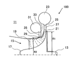
- FIG. 2 is a partial cross-sectional view showing a radial turbine shape when the radial turbine of the present invention is used as the expansion turbine of FIG.
- FIG. 3 is a projection view showing a state in which the radial blade of FIG. 2 is projected onto a cylindrical surface.
- the binary power generation system 3 is used as a system for performing geothermal power generation, for example.
- the binary power generation system 3 includes a heat source section 5 having a plurality of heat sources, two binary cycles 7A and 7B, an expansion turbine 1, and a generator 9 that generates electric power by the rotational power of the expansion turbine 1. And are provided.
- the heat source unit 5 supplies steam and hot water heated by geothermal heat to the binary cycles 7A and 7B.
- the heat source unit 5 is configured to supply two types of steam and hot water having different temperatures T1 and T2 and different pressures.
- the binary cycles 7A and 7B are constituted by a Rankine cycle in which a low boiling point medium (fluid) that is a working fluid is circulated.
- a low boiling point medium for example, an organic medium such as isobutane, chlorofluorocarbon, alternative chlorofluorocarbon, or a mixed fluid of ammonia, ammonia and water, or the like is used.
- the low boiling point medium is heated by the high-temperature steam and hot water from the heat source unit 5 to form a high-pressure fluid, which is supplied to the expansion turbine 1.
- the low boiling point medium discharged from the expansion turbine 1 is returned to the binary cycles 7A and 7B, heated again by high-temperature steam or hot water, and this is sequentially repeated.
- the same low boiling point medium is used in the two binary cycles 7A and 7B. Since the temperatures of the high-temperature steam and hot water supplied to the binary cycles 7A and 7B are different, the pressures P1 and P2 of the low boiling point medium supplied to the expansion turbine 1 are different. The pressure P1 is larger than the pressure P2.
- the radial turbine 100 includes a casing 11, a rotating shaft 13 that is rotatably supported by the casing 11, and a radial turbine wheel (turbine wheel) 15 that is attached to the outer periphery of the rotating shaft 13.
- the radial turbine wheel 15 is composed of a hub 17 attached to the outer periphery of the rotary shaft 13 and a plurality of radial blades 19 provided radially spaced on the outer peripheral surface of the hub 17.
- a main inlet 21 is formed at the outer peripheral end of the radial turbine wheel 15 at the radius R1 over the entire circumference.
- a main inflow passage 23 provided at one end of an inlet passage 25, which is an annular space into which a low-boiling point medium having a pressure P1 supplied from the binary cycle 7A is introduced, is formed.
- the main inflow channel 23 and the main inlet 21 are connected by an inlet channel 25.
- the inlet channel 25 is provided with a nozzle 27 that is composed of a plurality of blades arranged at intervals in the circumferential direction and generates a high-speed swirling flow. Further, a high-speed swirl flow may be generated by a high-speed swirl flow generation flow path such as a scroll having no nozzle blades.
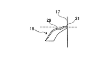
- a follower inlet 29 is formed at a position spaced apart from the main inlet 21 in the radial direction and the axial direction on the outer periphery (shroud) side of the radial turbine wheel 15.
- the secondary inlet path 31 provided at one end of the inlet flow path 33, which is an annular space into which the low boiling point medium having the pressure P ⁇ b> 2 supplied from the binary cycle 7 ⁇ / b> B is introduced at the position of the radius R ⁇ b> 2. Is formed.
- the secondary inflow channel 31 and the secondary inlet 29 are connected by an inlet channel 33.
- the inlet channel 33 is provided with a nozzle 35 composed of a plurality of blades arranged at intervals in the circumferential direction.
- a constant pressure line of the fluid passing through the radial turbine wheel 15 is indicated by a one-dot chain line.
- the radius R ⁇ b> 2 is set so that the pressure of the fluid supplied from the sub inlet 29 is substantially the same as the pressure of the fluid passing through this position in the radial turbine wheel 15.
- FIG. 3 is a projection view showing a state in which the radial blade of FIG. 2 is projected onto a cylindrical surface.
- the radial blade 19 has a radial blade shape at substantially the same angle with respect to the rotary shaft 13 on the hub 17 side of the main inlet portion 21, and parabolically toward the rotary shaft 13 toward the outlet of the radial turbine wheel 15.
- the wing shape increases the wing angle.
- the main inlet 21 and the secondary inlet 29 are formed at portions having substantially the same angle with respect to the rotary shaft 13 of the radial blade 19.
- the sub inlet 29 may be formed in a part where the angle of the blade with respect to the rotary shaft 13 increases in a parabolic shape.
- the flow rate and flow rate of the low boiling point medium having the pressure P1 supplied from the binary cycle 7A are adjusted from the main inflow path 23 through the inlet flow path 25 by the nozzle 27, and the low boiling point medium having the flow rate G1 is supplied from the main inlet 21 to the radial turbine. It is supplied to the outer peripheral end of the wheel 15. At this time, the pressure of the low boiling point medium supplied to the radial turbine wheel 15 is PN1.
- the flow rate and flow rate of the low boiling point medium having the pressure P2 supplied from the binary cycle 7B are adjusted by the nozzle 35 through the inlet flow path 31 through the inlet flow path 33, and the low boiling point medium having the flow rate G2 is adjusted to the secondary inlet 29.
- the low-boiling point pressure PN2 of the low-boiling-point medium supplied into the radial turbine wheel 15 from the sub-inlet 29 is sequentially lowered toward the outlet of the radial turbine wheel 15 flowing through the radial turbine wheel 15, in other words, the low-boiling point medium continuously decreasing. It is made to correspond to the pressure in the position of the sub inlet 29.
- the low boiling point medium having the flow rate G2 flowing in from the sub-inlet 29 is mixed with the low boiling point medium having the flow rate G1 supplied from the main inlet 21, and flows out from the outlet of the radial turbine wheel 15 together.
- a low boiling point medium having a flow rate that is a combination of the flow rate G1 and the flow rate G2 generates rotational power on the rotary shaft 13 via the radial turbine wheel 15.
- the generator 9 generates electric power by rotating the rotary shaft 13.
- the low-boiling-point media having different pressures from the binary cycles 7A and 7B are respectively supplied to the main inlet 21 and the sub-inlet 29 of the radial turbine wheel 15, thereby being taken out as rotational power by the single radial turbine wheel 15. be able to.
- the radial turbine 100 concerning this embodiment can reduce a number of parts compared with the expansion turbine provided with a some expansion turbine or a some radial turbine wheel, and can reduce manufacturing cost. it can.
- shroud is not provided in the radial turbine wheel 15, it is not limited to this.
- a shroud 37 may be attached to the radial turbine wheel 15 located between the main inlet 21 and the sub inlet 29. If it does in this way, the leakage loss of the low boiling-point medium by the clearance of the blade tip between the main inlet 21 and the sub inlet 29 can be reduced, and turbine efficiency can be made high.
- the pressure is gradually decreased toward the outlet, and in addition, since the low boiling point medium flows from the sub inlet 29, the volume flow rate of the low boiling point medium is decreased toward the downstream side. Increases, and the blade height for flowing the flow increases. For this reason, the blade height is the smallest between the main inlet 21 and the secondary inlet 29.
- the clearance between the casing 11 and the radial blade 19 is manufactured to be almost constant, the ratio of the clearance to the blade height is large between the main inlet 21 and the sub inlet 29, so that the leakage is large. Fluid loss due to leakage increases and efficiency decreases. As shown in FIG. 4, by installing a shroud 37 between the main inlet 21 and the sub inlet 29, the leakage loss of the low boiling point medium in this portion where the leakage is the highest can be reduced. The efficiency of the John turbine 1 can be increased.
- a shroud 39 may be provided between the secondary inlet 29 (the innermost secondary inlet) and the outlet (discharge portion) of the radial turbine wheel 15. . If it does in this way, since the leakage loss of a low boiling point medium can be reduced more, turbine efficiency can be made still higher. In this case, the shroud 37 may not be provided.
- the radial blades 19 at the outlet of the radial turbine wheel 15 are erected linearly in the radial direction, but are not limited thereto.
- the shape may be inclined with respect to the radial direction.
- 7 is a front view of the radial blade of FIG. 6 as viewed in the axial direction
- FIG. 8 is a perspective view of the radial blade of FIG. 6 as viewed in the radial direction.
- the sub inlet 29 is made into one place, you may make it provide in multiple places. If it does in this way, the low boiling point medium of three or more different pressures can be taken out as rotational power with the single radial turbine wheel 15, a number of parts can be reduced more, and manufacturing cost can be reduced.
- the present embodiment has been described as being applied to the binary power generation system 3 having two binary cycles 7A and 7B, the use of the expansion turbine 1 is not limited to this.
- the present invention can be applied to a binary power generation system 3 having one binary cycle 7C. This takes out low-boiling-point media having different pressures from the binary cycle 7 ⁇ / b> C and recovers power by the expansion turbine 1.
- the expansion turbine 1 may be used in the plant system 2 shown in FIG.
- the plant system 2 for example, in a boiler plant 4, a plurality of, for example, three steams (fluids) having different pressures are taken out and the power is recovered by the expansion turbine 1.
- the plant system 2 is various industrial plants, and may be used, for example, in a mixing process of a process in which separation or mixing is performed in a chemical plant.
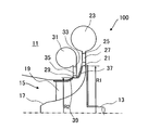
- FIG. 11 is a partial cross-sectional view showing a radial turbine 100 according to the second embodiment of the present invention.
- a radial turbine wheel 41 in which the hub surface at the inlet is inclined is used instead of the radial turbine wheel 15 of the first embodiment in which the hub surface at the inlet is in the radial direction as the turbine wheel.
- the radial turbine wheel 41 is provided with a plurality of blades 43 provided on the outer peripheral surface of the hub 17 at radially spaced intervals.
- the hub surface at the inlet of the hub 17 is inclined with respect to the radial direction. Accordingly, the main inflow channel 45 is inclined by an angle ⁇ 1 with respect to the radial direction.
- the secondary inflow path 47 is inclined at an angle ⁇ 2 with respect to the radial direction.
- the main inflow path 45 is composed of a plurality of blades arranged at intervals in the circumferential direction, and the secondary inflow path 47 is composed of a plurality of blades arranged at intervals in the circumferential direction.
- a nozzle 48 is provided.
- the operation of the radial turbine 100 according to the present embodiment configured as described above is basically the same as that of the radial turbine 100 of the first embodiment, a duplicate description is omitted here.
- blade 43 is inclined with respect to the radial direction, the axial direction length of an outer peripheral part can be lengthened. For this reason, since the space where the sub inlet 29 is installed can be widened, it becomes easy to manufacture.
- a sub inflow passage 53 is formed at a radius R3 where a low boiling point medium having a pressure lower than the pressure P2 is introduced.
- the secondary inflow channel 53 and the secondary inlet 51 are connected by an inlet channel 55 which is a donut-shaped space.
- the inlet channel 55 is provided with a nozzle 57 composed of a plurality of blades arranged at intervals in the circumferential direction. If it does in this way, the low boiling point medium of three or more different pressures can be taken out as rotational power with the single radial turbine wheel 41, a number of parts can be reduced more, and manufacturing cost can be reduced.
- the flow of the low boiling point medium flowing from the sub inlet 29 or the sub inlet 51 is directed from the upstream toward the outlet of the radial turbine wheel 41. Since it flows in substantially parallel to the flowing flow, the mixing loss of the low boiling point medium can be reduced. Thereby, the turbine efficiency of the radial turbine 100 can be improved.
- the shroud is not attached, but a shroud as shown in FIGS. 4 and 5 may be attached to reduce leakage loss. Further, the number of the sub inlets 29 and 51 may be increased.
Abstract
Description
これは、ラジアルタービンが流体のそれぞれの圧力に対し最適な条件に設計されるからである。たとえば、ラジアルタービンの入口半径Rは、重力加速度をg、ヘッドをH、タービンホイール入口周速をUとすると、g・H≒U2の関係で決まる。すなわち、タービンホイールの回転数をN(rpm)とすると、入口半径Rは、R≒U/2・π/(N/60)の近傍の値が設定される。 When various energy sources have a plurality of pressures, for example, as shown in
This is because the radial turbine is designed with optimum conditions for each pressure of the fluid. For example, the radial radius R of the radial turbine is determined by a relationship of g · H≈U 2 where g is the acceleration of gravity, H is the head, and U is the peripheral speed of the turbine wheel inlet. That is, assuming that the rotational speed of the turbine wheel is N (rpm), the inlet radius R is set to a value in the vicinity of R≈U / 2 · π / (N / 60).
また、同一軸に複数のタービンホイールを設ける場合、タービン部品点数が多く、構造が複雑となるし、製造コストが大きくなる。 As shown in
Further, when a plurality of turbine wheels are provided on the same shaft, the number of turbine parts is large, the structure becomes complicated, and the manufacturing cost increases.
すなわち、本発明の一態様は、第一の圧力を有し、ノズルやスクロールなどの高速旋回流発生流路を通って、外周端に形成された主入口から半径方向の流速成分を主要成分として持って流入する旋回する流体の旋回エネルギーを回転動力に変換する単一のタービンホイールを備えているラジアルタービンであって、前記タービンホイールの外周側に、前記主入口および相互に対し半径方向および軸方向に離隔した位置に複数の従入口が形成され、各従入口には、半径方向内側に行くほど前記第一の圧力よりも順次低くなる圧力を有する前記流体がそれぞれノズルやスクロールなどの高速旋回流発生流路を通って流入するように構成されているラジアルタービンである。 In order to solve the above problems, the present invention employs the following means.
That is, one aspect of the present invention has a first pressure, a flow velocity component in the radial direction from a main inlet formed at the outer peripheral end through a high-speed swirl flow passage such as a nozzle or a scroll. A radial turbine comprising a single turbine wheel for converting the turning energy of a turning fluid that flows into the rotary power into the outer peripheral side of the turbine wheel, the radial direction and the axis relative to the main inlet and each other A plurality of sub inlets are formed at positions spaced apart in the direction, and each of the sub inlets is swirled at a high speed such as a nozzle or a scroll by a fluid having a pressure that gradually decreases from the first pressure toward the inner side in the radial direction. A radial turbine configured to flow in through a flow generating flow path.
タービンホイールの外周側、言い換えれば、シュラウド側に、主入口および相互に対し半径方向および軸方向に離隔した位置に複数の従入口が形成されている。各従入口には、半径方向内側に行くほど第一の圧力よりも順次低くなる圧力を有する流体がそれぞれノズルやスクロールなどの高速旋回流発生流路を通って流入するように構成されているので、各従入口では、それぞれ圧力が順次低下された流体がノズルを通って流量、流速等を調整されて導入される。各従入口から導入された流体は、上流側の主入口および従入口から導入された流体と混合され、順次圧力を低減されつつタービンホイールから流出し、タービンホイールが取り付けられている回転軸に動力を発生させる。 According to this aspect, the fluid of the first pressure, which is the highest pressure, is adjusted in flow rate, flow velocity, etc. through a high-speed swirl flow generation passage such as a nozzle or a scroll, and introduced from the main inlet to the outer peripheral end of the turbine wheel. Is done. The fluid introduced into the main inlet flows out of the turbine wheel while reducing the pressure sequentially through the turbine wheel, and generates power on the rotating shaft to which the turbine wheel is attached.
On the outer peripheral side of the turbine wheel, in other words, on the shroud side, a plurality of sub inlets are formed at positions separated from each other in the radial direction and the axial direction with respect to the main inlet and each other. Each of the sub inlets is configured such that a fluid having a pressure that is sequentially lower than the first pressure as it goes radially inward flows through a high-speed swirl flow generation passage such as a nozzle or a scroll. In each sub-inlet, a fluid whose pressure is sequentially reduced is introduced through the nozzle with the flow rate, the flow rate, etc. adjusted. The fluid introduced from each of the slave inlets is mixed with the fluid introduced from the upstream main inlet and the slave inlets, and then flows out of the turbine wheel while reducing the pressure in order, and power is supplied to the rotating shaft to which the turbine wheel is attached. Is generated.
主入口と従入口との間および各従入口間には、ケーシングが存在しているので、明確に区別され、流体の漏出を防止することができる。
このように、複数の圧力を有する流体を、単一のタービンホイールによって回転動力として取り出すことができる。これにより、部品点数を低減することができ、製造コストを低減することができる。 At this time, it is preferable that the sub inlet is installed at a position where the pressure of the introduced fluid coincides with the pressure that gradually decreases toward the outlet flowing through the turbine wheel.
Since a casing exists between the main inlet and the sub inlet and between each sub inlet, it can be clearly distinguished and fluid leakage can be prevented.
Thus, a fluid having a plurality of pressures can be taken out as rotational power by a single turbine wheel. Thereby, a number of parts can be reduced and manufacturing cost can be reduced.
このように、入口におけるハブ面が傾斜したタービンホイールを用いると、外周部の軸方向長さが長くなるので、従入口を設置するスペースが広くなる。これにより、従入口を多数設置することが容易になる。
また、従入口に設置されるノズルを半径に対して傾斜させると、従入口から流入する流体の流れが、上流からタービンホイール出口に向けて流れる流れとほぼ平行に流入するようにできるので、流体の混合損失を低減できる。これにより、タービン効率を高くすることができる。 The radial turbine of this aspect includes the one in which the hub surface at the inlet of the turbine wheel is inclined.
As described above, when a turbine wheel having an inclined hub surface at the inlet is used, the axial length of the outer peripheral portion is increased, so that a space for installing the sub inlet is increased. This makes it easy to install a large number of sub inlets.
In addition, if the nozzle installed at the slave inlet is inclined with respect to the radius, the flow of fluid flowing from the slave inlet can flow in substantially parallel to the flow flowing from the upstream toward the turbine wheel outlet. Can be reduced. Thereby, turbine efficiency can be made high.
一方、ケーシングと翼のクリアランスはほぼ一定に製作されるので、主入口と最も外側に位置する従入口との間では、翼高さに対してクリアランスの割合が大きくなるので、漏れが大きく、漏れによる流体損失が増加し効率が低下する。
本態様では、主入口と最も外側に位置する従入口との間にシュラウドを設置することにより、最も漏れの多いこの部分での流体の漏れ損失を低減することができ、タービン効率を高くすることができる。 In the turbine wheel, the pressure gradually decreases toward the outlet, and in addition, fluid flows in from each of the sub inlets installed at different radial positions, so that the fluid flows toward the downstream side. The volume flow rate increases, and the blade height for flowing the flow increases. For this reason, the blade height is the smallest between the main inlet and the slave inlet located on the outermost side.
On the other hand, since the clearance between the casing and the blade is made almost constant, the ratio of the clearance to the blade height is large between the main inlet and the outermost slave inlet, so the leakage is large and the leakage is large. Increases fluid loss and decreases efficiency.
In this aspect, by installing a shroud between the main inlet and the subordinate inlet located on the outermost side, it is possible to reduce the leakage loss of the fluid in this portion with the highest leakage, and to increase the turbine efficiency. Can do.
また、上記態様では、前記タービンホイールには、最も内側に位置する前記従入口から吐出部の間にシュラウドが設けられていてもよい。 In the above aspect, the turbine wheel may be provided with a shroud between the slave inlets.
Moreover, in the said aspect, the shroud may be provided in the said turbine wheel between the said sub inlet located in the innermost side and a discharge part.
[第一実施形態]
以下、本発明の第一実施形態にかかるラジアルタービン100について図1~図3を参照して説明する。
図1は、本発明の第一実施形態にかかるエキスパンジョンタービンが用いられているバイナリー発電システムの構成を示すブロック図である。図2は、図1のエキスパンジョンタービンとして本発明のラジアルタービンが使用される場合のラジアルタービン形状を示す部分断面図である。図3は、図2のラジアル翼を円筒面に投影した状態を示す投影図である。 Hereinafter, embodiments of the present invention will be described in detail with reference to the drawings.
[First embodiment]
A
FIG. 1 is a block diagram showing a configuration of a binary power generation system in which an expansion turbine according to a first embodiment of the present invention is used. FIG. 2 is a partial cross-sectional view showing a radial turbine shape when the radial turbine of the present invention is used as the expansion turbine of FIG. FIG. 3 is a projection view showing a state in which the radial blade of FIG. 2 is projected onto a cylindrical surface.
バイナリーサイクル7A,7Bは、作動流体である低沸点媒体(流体)を循環させるランキンサイクルで構成されている。低沸点媒体としては、たとえば、イソブタン等の有機媒体、フロン、代替フロン、またはアンモニアやアンモニアと水の混合流体、等が用いられる。 The
The
このとき、2つのバイナリーサイクル7A,7Bでは、同じ低沸点媒体が用いられている。バイナリーサイクル7A,7Bに供給される高温蒸気や熱水の温度が異なるので、それらからエキスパンジョンタービン1に供給される低沸点媒体の圧力P1、P2は異なっている。圧力P1が圧力P2よりも大きい。 In the binary cycles 7 </ b> A and 7 </ b> B, the low boiling point medium is heated by the high-temperature steam and hot water from the
At this time, the same low boiling point medium is used in the two
ラジアルタービンホイール15は、回転軸13の外周に取り付けられたハブ17とハブ17の外周面に放射状に間隔を空けて備えられた複数のラジアル翼19とで構成されている。 The
The
入口流路25には、周方向に間隔を空けて配置された複数の翼から構成され高速旋回流を発生させるノズル27が設けられている。
また、ノズル翼を有しないスクロールなどの高速旋回流発生流路により高速旋回流を発生させるようにしても良い。 A
The
Further, a high-speed swirl flow may be generated by a high-speed swirl flow generation flow path such as a scroll having no nozzle blades.
入口流路33には、周方向に間隔を空けて配置された複数の翼から構成されるノズル35が設けられている。 A
The
半径R2は、従入口29から供給される流体の圧力が、ラジアルタービンホイール15内でこの位置を通る流体の圧力と略同一となるように設定されている。 In FIG. 2, a constant pressure line of the fluid passing through the
The radius R <b> 2 is set so that the pressure of the fluid supplied from the
ラジアル翼19は、主入口部21のハブ17側は回転軸13に対してほぼ同一の角度の放射状の翼形状を有し、ラジアルタービンホイール15の出口に向けて放物線状に回転軸13に対して翼の角度が大きくなるという翼形状とされている。
主入口21および従入口29は、ラジアル翼19の回転軸13に対してほぼ同一の角度を有する部分に形成されている。
従入口29は、放物線状に回転軸13に対して翼の角度が大きくなる部分に形成するようにしてもよい。 FIG. 3 is a projection view showing a state in which the radial blade of FIG. 2 is projected onto a cylindrical surface.
The
The
The
バイナリーサイクル7Aから供給される圧力P1の低沸点媒体は、主流入路23から入口流路25を通ってノズル27によって流量、流速を調整され、流量G1の低沸点媒体が主入口21からラジアルタービンホイール15の外周端に供給される。このとき、ラジアルタービンホイール15に供給される低沸点媒体の圧力はPN1である。この圧力PN1の低沸点媒体は、ラジアルタービンホイール15の出口圧Pdまで連続的に圧力が低下しながらラジアルタービンホイール15から流出し、ラジアルタービンホイール15が取り付けられている回転軸13に回転動力を発生させる。 Hereinafter, the operation of the
The flow rate and flow rate of the low boiling point medium having the pressure P1 supplied from the
回転軸13の回転駆動によって発電機9が電力を発生させる。 The low boiling point medium having the flow rate G2 flowing in from the sub-inlet 29 is mixed with the low boiling point medium having the flow rate G1 supplied from the
The
これにより、本実施形態にかかるラジアルタービン100は、複数のエキスパンジョンタービンあるいは複数のラジアルタービンホイールを備えるエキスパンジョンタービンに比べて部品点数を低減することができ、製造コストを低減することができる。 In this way, the low-boiling-point media having different pressures from the
Thereby, the
たとえば、図4に示されるように、主入口21と従入口29との間に位置するラジアルタービンホイール15にシュラウド37を取り付けてもよい。
このようにすると、主入口21と従入口29との間における翼先端のクリアランスによる低沸点媒体の漏れ損失を低減することができ、タービン効率を高くすることができる。 In this embodiment, although the shroud is not provided in the
For example, as shown in FIG. 4, a
If it does in this way, the leakage loss of the low boiling-point medium by the clearance of the blade tip between the
一方、ケーシング11とラジアル翼19とのクリアランスはほぼ一定に製作されるので、主入口21と従入口29との間では、翼高さに対してクリアランスの割合が大きくなるので、漏れが大きく、漏れによる流体損失が増加し効率が低下する。
図4に示されるように、主入口21と従入口29との間にシュラウド37を設置することにより、最も漏れの多いこの部分での低沸点媒体の漏れ損失を低減することができ、エキスパンジョンタービン1の効率を高くすることができる。 That is, in the
On the other hand, since the clearance between the
As shown in FIG. 4, by installing a
このようにすると、低沸点媒体の漏れ損失をより低減することができるので、タービン効率を一層高くすることができる。
この場合、シュラウド37を設けないようにしてもよい。 Further, as shown in FIG. 5, in addition to the
If it does in this way, since the leakage loss of a low boiling point medium can be reduced more, turbine efficiency can be made still higher.
In this case, the
図7は、図6のラジアル翼を軸線方向に見た正面図、図8は、図6のラジアル翼を半径方向に見た斜視図である。 In the present embodiment, the
7 is a front view of the radial blade of FIG. 6 as viewed in the axial direction, and FIG. 8 is a perspective view of the radial blade of FIG. 6 as viewed in the radial direction.
このようにすると、3以上の異なる圧力の低沸点媒体を単一のラジアルタービンホイール15によって回転動力として取り出すことができ、より部品点数を低減することができ、製造コストを低減することができる。 Furthermore, in this embodiment, although the
If it does in this way, the low boiling point medium of three or more different pressures can be taken out as rotational power with the single
たとえば、図9に示されるように、1つのバイナリーサイクル7Cを有するバイナリー発電システム3にも適用できる。これはバイナリーサイクル7Cから圧力の異なる低沸点媒体を取り出してエキスパンジョンタービン1によって動力を回収する。 Although the present embodiment has been described as being applied to the binary power generation system 3 having two
For example, as shown in FIG. 9, the present invention can be applied to a binary power generation system 3 having one
プラントシステム2としては、各種産業プラントであり、たとえば、化学プラントにおいて分離や混合が行われるプロセスの混合過程に使用されても良い。 Further, the
The
次に、本発明の第二実施形態にかかるラジアルタービン100について、図11を用いて説明する。
本実施形態は、タービンホイールの構成が第一実施形態のものと異なるので、ここではこの異なる部分について主として説明し、前述した第一実施形態のものと同じ部分については重複した説明を省略する。
第一実施形態と同じ部材には同じ符号を付している。 [Second Embodiment]
Next, the
In this embodiment, since the configuration of the turbine wheel is different from that of the first embodiment, the different parts will be mainly described here, and the same parts as those of the first embodiment described above will not be described.
The same members as those in the first embodiment are denoted by the same reference numerals.
本実施形態では、タービンホイールとして入口におけるハブ面が半径方向となっている第一実施形態のラジアルタービンホイール15に替えて入口におけるハブ面が傾斜しているラジアルタービンホイール41が用いられている。ラジアルタービンホイール41には、ハブ17の外周面に放射状に間隔を空けて備えられた複数の翼43が備えられている。ハブ17の入口におけるハブ面は半径方向に対し傾斜している。これに伴い、主流入路45は、半径方向に対して角度α1傾斜している。従流入路47は、半径方向に対して角度α2傾斜している。
主流入路45には周方向に間隔を空けて配置された複数の翼から構成されるノズル46が、従流入路47には、周方向に間隔を空けて配置された複数の翼から構成されるノズル48が設けられている。 FIG. 11 is a partial cross-sectional view showing a
In the present embodiment, a
The
本実施形態では、翼43の外周側が半径方向に対して傾斜されているので、外周部の軸方向長さを長くすることができる。このため、従入口29を設置するスペースを広くすることができるので、製造し易くなる。 Since the operation of the
In this embodiment, since the outer peripheral side of the wing |
このようにすると、3以上の異なる圧力の低沸点媒体を単一の斜流タービンホイール41によって回転動力として取り出すことができ、より部品点数を低減することができ、製造コストを低減することができる。従入口51の外周側には、半径R3の位置に圧力P2よりも低い圧力の低沸点媒体が導入される従流入路53が形成されている。従流入路53と従入口51とは、ドーナツ状の空間である入口流路55で接続されている。
入口流路55には、周方向に間隔を空けて配置された複数の翼から構成されるノズル57が設けられている。
このようにすると、3以上の異なる圧力の低沸点媒体を単一のラジアルタービンホイール41によって回転動力として取り出すことができ、より部品点数を低減することができ、製造コストを低減することができる。 Thereby, it becomes easy to install
If it does in this way, the low boiling point medium of three or more different pressures can be taken out as rotational power with the single mixed
The
If it does in this way, the low boiling point medium of three or more different pressures can be taken out as rotational power with the single
また、従入口29,51の個数を増加させてもよい。 In this embodiment, the shroud is not attached, but a shroud as shown in FIGS. 4 and 5 may be attached to reduce leakage loss.
Further, the number of the
15 ラジアルタービンホイール
19 ラジアル翼
21 主入口
27 ノズル
29 従入口
35 ノズル
41 ラジアルタービンホイール
43 翼
45 主流入路
46 ノズル
48 ノズル
51 従入口
57 ノズル
100 ラジアルタービン DESCRIPTION OF
Claims (4)
- 第一の圧力を有し、ノズルやスクロールなどの高速旋回流発生流路を通って、外周端に形成された主入口から半径方向の流速成分を主要成分として持って流入する旋回する流体の旋回エネルギーを回転動力に変換する単一のタービンホイールを備えているラジアルタービンであって、
前記タービンホイールの外周側に、前記主入口および相互に対し半径方向および軸方向に離隔した位置に複数の従入口が形成され、
各従入口には、半径方向内側に行くほど前記第一の圧力よりも順次低くなる圧力を有する前記流体がそれぞれノズルやスクロールなどの高速旋回流発生流路を通って旋回する流体が流入するように構成されているラジアルタービン。 Swirl of a swirling fluid that has a first pressure and flows through a high-speed swirling flow generation passage such as a nozzle or a scroll from a main inlet formed at the outer peripheral end with a radial flow velocity component as a main component A radial turbine having a single turbine wheel that converts energy into rotational power,
On the outer peripheral side of the turbine wheel, a plurality of sub inlets are formed at positions spaced apart in the radial direction and the axial direction with respect to the main inlet and each other,
Each of the sub inlets has a fluid swirling through a high-speed swirling flow passage such as a nozzle or a scroll that has a pressure that gradually decreases from the first pressure as it goes radially inward. Radial turbine that is configured to. - 前記タービンホイールには、前記主入口と最も外側に位置する前記従入口との間にシュラウドが設けられている請求項1に記載のラジアルタービン。 The radial turbine according to claim 1, wherein the turbine wheel is provided with a shroud between the main inlet and the sub inlet located on the outermost side.
- 前記タービンホイールには、前記各従入口の間にシュラウドが設けられている請求項1または2に記載のラジアルタービン。 The radial turbine according to claim 1 or 2, wherein the turbine wheel is provided with a shroud between the sub inlets.
- 前記タービンホイールには、最も内側に位置する前記従入口から吐出部の間にシュラウドが設けられている請求項1から3のいずれかに記載のラジアルタービン。 The radial turbine according to any one of claims 1 to 3, wherein the turbine wheel is provided with a shroud between the innermost slave inlet and a discharge portion.
Priority Applications (4)
| Application Number | Priority Date | Filing Date | Title |
|---|---|---|---|
| US13/812,740 US20130121819A1 (en) | 2010-12-07 | 2011-01-24 | Radial turbine |
| EP11846316.5A EP2650473A1 (en) | 2010-12-07 | 2011-01-24 | Radial turbine |
| KR1020137001809A KR20130023368A (en) | 2010-12-07 | 2011-01-24 | Radial turbine |
| CN2011800378645A CN103052763A (en) | 2010-12-07 | 2011-01-24 | Radial turbine |
Applications Claiming Priority (2)
| Application Number | Priority Date | Filing Date | Title |
|---|---|---|---|
| JP2010272764A JP2012122377A (en) | 2010-12-07 | 2010-12-07 | Radial turbine |
| JP2010-272764 | 2010-12-07 |
Publications (1)
| Publication Number | Publication Date |
|---|---|
| WO2012077359A1 true WO2012077359A1 (en) | 2012-06-14 |
Family
ID=46206869
Family Applications (1)
| Application Number | Title | Priority Date | Filing Date |
|---|---|---|---|
| PCT/JP2011/051254 WO2012077359A1 (en) | 2010-12-07 | 2011-01-24 | Radial turbine |
Country Status (6)
| Country | Link |
|---|---|
| US (1) | US20130121819A1 (en) |
| EP (1) | EP2650473A1 (en) |
| JP (1) | JP2012122377A (en) |
| KR (1) | KR20130023368A (en) |
| CN (1) | CN103052763A (en) |
| WO (1) | WO2012077359A1 (en) |
Families Citing this family (4)
| Publication number | Priority date | Publication date | Assignee | Title |
|---|---|---|---|---|
| JP6413980B2 (en) * | 2014-09-04 | 2018-10-31 | 株式会社デンソー | Turbocharger exhaust turbine |
| GB2561837A (en) * | 2017-04-24 | 2018-10-31 | Hieta Tech Limited | Turbine rotor, turbine, apparatus and method |
| CN108049919B (en) * | 2017-10-23 | 2024-03-26 | 陈朝晖 | Environmental protection energy-saving door station gas transmission pipeline pressure difference rotary spraying type power machine |
| CN113153461B (en) * | 2021-04-15 | 2022-12-02 | 中国航发湖南动力机械研究所 | Exhaust tail cone and radial turbine adopting same |
Citations (10)
| Publication number | Priority date | Publication date | Assignee | Title |
|---|---|---|---|---|
| JPS4628042B1 (en) * | 1969-08-28 | 1971-08-14 | ||
| JPS52109018A (en) * | 1976-03-09 | 1977-09-12 | Ishikawajima Harima Heavy Ind Co Ltd | Radial-flow turbine |
| JPS61211516A (en) * | 1985-03-18 | 1986-09-19 | Hitachi Ltd | Micro-expansion turbine |
| JPS61179303U (en) * | 1985-04-27 | 1986-11-08 | ||
| JPS61202601U (en) * | 1985-06-10 | 1986-12-19 | ||
| JPS63302134A (en) | 1987-06-01 | 1988-12-09 | Hitachi Ltd | Exhaust gas turbine supercharger |
| JPH01285607A (en) | 1988-05-07 | 1989-11-16 | Hisaka Works Ltd | Hybrid binary generating system |
| JPH05263601A (en) * | 1991-11-15 | 1993-10-12 | Praxair Technol Inc | Impeller stress improvement through overspeed |
| US20030115875A1 (en) * | 2001-10-25 | 2003-06-26 | Siegfried Sumser | Internal combustion engine with an exhaust turbocharger and an exhaust-gas recirculation device |
| JP2007023893A (en) * | 2005-07-15 | 2007-02-01 | Toyota Motor Corp | Turbocharger |
Family Cites Families (9)
| Publication number | Priority date | Publication date | Assignee | Title |
|---|---|---|---|---|
| JPS55164708A (en) * | 1979-06-08 | 1980-12-22 | Hitachi Ltd | Steam control for mixed-pressure steam turbine and its steam controlling apparatus |
| DE2934041C2 (en) * | 1979-08-23 | 1983-08-11 | Günther Prof. Dr.-Ing. 5100 Aachen Dibelius | Controlled exhaust gas turbocharger turbine |
| JPH0628042B2 (en) * | 1986-01-31 | 1994-04-13 | 富士通株式会社 | How to update the journal version |
| JP2008008227A (en) * | 2006-06-29 | 2008-01-17 | Toyota Motor Corp | Variable capacity turbine |
| CN101368486A (en) * | 2007-01-04 | 2009-02-18 | 邓永凯 | Supercharging centrifugal type gas cylinder/water vat engine |
| JP2008196332A (en) * | 2007-02-09 | 2008-08-28 | Toyota Motor Corp | Control device for internal combustion engine with turbocharger |
| CN101178011B (en) * | 2007-11-23 | 2012-07-25 | 西安交通大学 | Impeller structure of centripetal turbine |
| JP2010013972A (en) * | 2008-07-02 | 2010-01-21 | Toyota Motor Corp | Variable capacity type turbocharger |
| US8424304B2 (en) * | 2009-11-03 | 2013-04-23 | Honeywell International Inc. | Turbine assembly for a turbocharger, having two asymmetric volutes that are sequentially activated, and associated method |
-
2010
- 2010-12-07 JP JP2010272764A patent/JP2012122377A/en active Pending
-
2011
- 2011-01-24 EP EP11846316.5A patent/EP2650473A1/en not_active Withdrawn
- 2011-01-24 KR KR1020137001809A patent/KR20130023368A/en not_active Application Discontinuation
- 2011-01-24 WO PCT/JP2011/051254 patent/WO2012077359A1/en active Application Filing
- 2011-01-24 CN CN2011800378645A patent/CN103052763A/en active Pending
- 2011-01-24 US US13/812,740 patent/US20130121819A1/en not_active Abandoned
Patent Citations (10)
| Publication number | Priority date | Publication date | Assignee | Title |
|---|---|---|---|---|
| JPS4628042B1 (en) * | 1969-08-28 | 1971-08-14 | ||
| JPS52109018A (en) * | 1976-03-09 | 1977-09-12 | Ishikawajima Harima Heavy Ind Co Ltd | Radial-flow turbine |
| JPS61211516A (en) * | 1985-03-18 | 1986-09-19 | Hitachi Ltd | Micro-expansion turbine |
| JPS61179303U (en) * | 1985-04-27 | 1986-11-08 | ||
| JPS61202601U (en) * | 1985-06-10 | 1986-12-19 | ||
| JPS63302134A (en) | 1987-06-01 | 1988-12-09 | Hitachi Ltd | Exhaust gas turbine supercharger |
| JPH01285607A (en) | 1988-05-07 | 1989-11-16 | Hisaka Works Ltd | Hybrid binary generating system |
| JPH05263601A (en) * | 1991-11-15 | 1993-10-12 | Praxair Technol Inc | Impeller stress improvement through overspeed |
| US20030115875A1 (en) * | 2001-10-25 | 2003-06-26 | Siegfried Sumser | Internal combustion engine with an exhaust turbocharger and an exhaust-gas recirculation device |
| JP2007023893A (en) * | 2005-07-15 | 2007-02-01 | Toyota Motor Corp | Turbocharger |
Also Published As
| Publication number | Publication date |
|---|---|
| CN103052763A (en) | 2013-04-17 |
| KR20130023368A (en) | 2013-03-07 |
| US20130121819A1 (en) | 2013-05-16 |
| EP2650473A1 (en) | 2013-10-16 |
| JP2012122377A (en) | 2012-06-28 |
Similar Documents
| Publication | Publication Date | Title |
|---|---|---|
| JP5449219B2 (en) | Radial turbine | |
| JP6128656B2 (en) | Apparatus and process for generating energy by organic Rankine cycle | |
| JP5909163B2 (en) | Operation method of two-pressure radial turbine | |
| WO2012077359A1 (en) | Radial turbine | |
| US9228588B2 (en) | Turbomachine component temperature control | |
| JP4885302B1 (en) | Radial turbine | |
| KR20150080911A (en) | Steam turbine and methods of assembling the same | |
| WO2013025341A1 (en) | Parallel cascaded cycle gas expander | |
| JP2012122377A5 (en) | ||
| EP3748130B1 (en) | Axial flow rotary machine | |
| US9322414B2 (en) | Turbomachine | |
| JP2011241812A (en) | Reaction radial flow steam turbine | |
| WO2021220950A1 (en) | Sealing device and dynamo-electric machine | |
| JP5832393B2 (en) | Two-pressure radial turbine | |
| KR20140000381A (en) | Reaction type turbine | |
| JP2012062876A (en) | Radial flow reaction steam turbine with only moving blade | |
| JP5698888B2 (en) | Radial flow steam turbine | |
| JP2007211676A (en) | Steam turbine and solar heat rankine system using the same | |
| JP2014092052A (en) | Turbine power generation system | |
| JP2013249746A (en) | Dual-pressure radial turbine |
Legal Events
| Date | Code | Title | Description |
|---|---|---|---|
| WWE | Wipo information: entry into national phase |
Ref document number: 201180037864.5 Country of ref document: CN |
|
| 121 | Ep: the epo has been informed by wipo that ep was designated in this application |
Ref document number: 11846316 Country of ref document: EP Kind code of ref document: A1 |
|
| ENP | Entry into the national phase |
Ref document number: 20137001809 Country of ref document: KR Kind code of ref document: A |
|
| WWE | Wipo information: entry into national phase |
Ref document number: 13812740 Country of ref document: US |
|
| WWE | Wipo information: entry into national phase |
Ref document number: 2011846316 Country of ref document: EP |
|
| NENP | Non-entry into the national phase |
Ref country code: DE |