WO2012074099A1 - 排気装置の制御方法及び排気装置の制御装置 - Google Patents
排気装置の制御方法及び排気装置の制御装置 Download PDFInfo
- Publication number
- WO2012074099A1 WO2012074099A1 PCT/JP2011/077928 JP2011077928W WO2012074099A1 WO 2012074099 A1 WO2012074099 A1 WO 2012074099A1 JP 2011077928 W JP2011077928 W JP 2011077928W WO 2012074099 A1 WO2012074099 A1 WO 2012074099A1
- Authority
- WO
- WIPO (PCT)
- Prior art keywords
- exhaust
- vacuum
- valve
- controlled
- pressure control
- Prior art date
- Legal status (The legal status is an assumption and is not a legal conclusion. Google has not performed a legal analysis and makes no representation as to the accuracy of the status listed.)
- Ceased
Links
Images












Classifications
-
- F—MECHANICAL ENGINEERING; LIGHTING; HEATING; WEAPONS; BLASTING
- F04—POSITIVE - DISPLACEMENT MACHINES FOR LIQUIDS; PUMPS FOR LIQUIDS OR ELASTIC FLUIDS
- F04D—NON-POSITIVE-DISPLACEMENT PUMPS
- F04D27/00—Control, e.g. regulation, of pumps, pumping installations or pumping systems specially adapted for elastic fluids
- F04D27/02—Surge control
- F04D27/0269—Surge control by changing flow path between different stages or between a plurality of compressors; load distribution between compressors
-
- F—MECHANICAL ENGINEERING; LIGHTING; HEATING; WEAPONS; BLASTING
- F04—POSITIVE - DISPLACEMENT MACHINES FOR LIQUIDS; PUMPS FOR LIQUIDS OR ELASTIC FLUIDS
- F04B—POSITIVE-DISPLACEMENT MACHINES FOR LIQUIDS; PUMPS
- F04B49/00—Control, e.g. of pump delivery, or pump pressure of, or safety measures for, machines, pumps, or pumping installations, not otherwise provided for, or of interest apart from, groups F04B1/00 - F04B47/00
- F04B49/06—Control using electricity
- F04B49/065—Control using electricity and making use of computers
-
- F—MECHANICAL ENGINEERING; LIGHTING; HEATING; WEAPONS; BLASTING
- F04—POSITIVE - DISPLACEMENT MACHINES FOR LIQUIDS; PUMPS FOR LIQUIDS OR ELASTIC FLUIDS
- F04D—NON-POSITIVE-DISPLACEMENT PUMPS
- F04D19/00—Axial-flow pumps
- F04D19/02—Multi-stage pumps
- F04D19/04—Multi-stage pumps specially adapted to the production of a high vacuum, e.g. molecular pumps
- F04D19/046—Combinations of two or more different types of pumps
Definitions
- the present invention relates to an exhaust apparatus control method and an exhaust apparatus control apparatus in a vacuum apparatus having a plurality of exhaust apparatuses.
- the substrate processing apparatus generally performs processing such as etching and film formation on the substrate after the inside is depressurized by an exhaust device such as a pump.
- a pump For example, in Patent Document 1, a plurality of pumps are connected in parallel to a single vacuum chamber, and the degree of opening of the butterfly valve on the high vacuum pump side is adjusted according to the target pressure. Stable vacuuming up to vacuum.
- the pump is composed of a roughing pump and a high vacuum pump, and different types of pumps are connected in parallel.
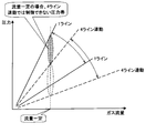
- the range in which the pressure inside the apparatus can be controlled is a dotted line in relation to the gas flow rate.
- the inventor has found that there is a region in which the pressure and flow rate cannot be controlled because the region is limited to the triangular region shown.
- Patent Document 1 two lines of a line connected to a roughing pump and a line connected to a high vacuum pump are provided, and one of different pumps is selected according to a target pressure, and a line (pump) However, it is not configured to connect the same type of pumps in parallel.
- the present invention provides an exhaust device control method and exhaust system capable of controlling pressure and gas flow rate over a wider range by using a plurality of exhaust devices each arranged in parallel with a vacuum device.
- An object of the present invention is to provide a control device for a device.
- a control method for a plurality of exhaust devices provided in a vacuum device wherein the flow rate of gas introduced into the vacuum device decreases as the gas flow decreases.
- a control method for a plurality of exhaust devices provided in a vacuum device wherein each exhaust device increases as the pressure in the vacuum device increases.
- a setting step for setting a linked or unlinked state of the plurality of exhaust devices so as to reduce the number of exhaust devices that are controlled in conjunction with each other and increase the number of exhaust devices that are controlled in a synchronized manner, and the set state
- an exhaust process for exhausting the vacuum apparatus using at least one of the plurality of exhaust apparatuses is provided.
- the number of exhaust devices controlled in conjunction with each other is reduced, and the number of exhaust devices controlled in an interlocked manner is increased. Set the non-linked state.
- the number of exhaust devices controlled in conjunction with each exhaust device is reduced, and the number of exhaust devices controlled in conjunction with each other is increased or decreased. Set the interlock status.
- the controllable pressure band is different between the case where the four-line exhaust system is operated in conjunction with the case where the one-line exhaust system is operated independently.
- the triangular area in FIG. 1 is a range that cannot be controlled when a four-line exhaust system is operated in conjunction, but is a range that can be controlled when a single-line exhaust system is operated alone. Therefore, by changing the interlocking / non-interlocking setting of the exhaust device, the pressure range that can be controlled in response to the change in the gas flow rate can be widened, and the pressure fluctuation in the vacuum vessel can be suppressed. Even in a process that needs to perform pressure control over a wide range from low vacuum to high vacuum, the controllable pressure zone can be widened, so that fluctuations in pressure in the vacuum vessel can be suppressed.
- a vacuum apparatus control comprising a plurality of exhaust apparatuses connected in parallel to a single vacuum chamber and evacuating the space in the vacuum chamber.
- a method of controlling a vacuum device provided.
- a vacuum apparatus control comprising a plurality of exhaust apparatuses connected in parallel to a single vacuum chamber and evacuating the space in the vacuum chamber.
- a method of controlling a vacuum device provided.
- a plurality of exhaust device control devices provided in a vacuum device, the smaller the flow rate of gas introduced into the vacuum device,
- a setting control unit configured to set a linked or unlinked state of the plurality of exhaust devices so as to reduce the number of exhaust devices to be controlled in conjunction and increase the number of exhaust devices to be controlled unsynchronously; and the set state
- an exhaust control unit that exhausts the vacuum device using at least one of the plurality of exhaust devices.
- shut-off valve and the pressure control valve shown in FIG. 6 are other examples of a valve having a shut-off function
- the APC valve shown in FIG. 12 is also an example of a valve having a shut-off function. It is an example.
- the APC valve is an integrated shutoff valve and pressure control valve.
- “linked” means, for example, that a valve having a slave shut-off function connected to a master is linked to a valve having a master shut-off function shown in FIG.
- “Non-interlocking” means that a valve having a slave shut-off function connected to a master in a daisy chain is not operated in conjunction with a valve having a master shut-off function.
- the valve opening is fixed to a predetermined opening that is not interlocked with the operation of other valves.
- “Full open (non-interlocking)” state in which the valve operation is fixed to the maximum opening in a non-linked manner, and the valve opening is fixed to the minimum opening in a non-linked manner with other valve openings. There is a “full closed (non-interlocked)” state to operate.
- the pressure band that can be controlled is limited to some extent due to its structure.
- the same opening degree is obtained by interlocking the four exhaust devices.
- the usable pressure zone is limited by the range of opening of the pressure control valve.
- the triangular zone between the pressure control line SC when the pressure control valves of the four exhaust devices are most closed and the pressure control line SO when the pressure control valve is most opened is the pressure and flow control. It is a possible area.
- each exhaust device may be set so that four exhaust devices are operated at the same time, or six exhaust devices.
- Each exhaust device may be set so as to operate simultaneously with each other.
- the process conditions are set such that the pressure and the gas flow rate become the point C2
- the respective exhaust devices are set so that the six exhaust devices are operated simultaneously.
- each exhaust device can be set to operate.
- each exhaust device is set so that the four exhaust devices are operated in conjunction with each other or the six exhaust devices are operated in conjunction with each other. can do.
- each exhaust device can be set so that the two exhaust devices are operated in conjunction with each other.
- each exhaust device is set so that two exhaust devices are interlocked or four exhaust devices are operated in conjunction with each other. Can do.
- the control in the setting step, is interlocked as the flow rate of the gas introduced into the vacuum device decreases. If the interlocking or non-interlocking state of the plurality of exhaust devices is set so as to reduce the number of exhaust devices to be controlled and increase the number of exhaust devices to be controlled non-interactively, the pressure and gas flow rate can be controlled in a wider range. it can.
- the vacuum apparatus is exhausted using at least one of the plurality of exhaust apparatuses in the set state. Thereby, the inside of the vacuum device can be maintained at a predetermined pressure.
- the control is performed in conjunction with each exhaust device as the pressure in the vacuum device increases.
- the state of interlocking or non-interlocking of the plurality of exhaust devices is set so as to reduce the number of exhaust devices to be operated and increase the number of exhaust devices to be controlled non-interactively.
- the vacuum apparatus is exhausted using at least one of the plurality of exhaust apparatuses in the set state. This also makes it possible to control the pressure and gas flow rate over a wider range.
- points C5 and C6 in FIG. 4 are pressure zones that cannot be controlled when a 6-line exhaust system operates in conjunction with each other, but are controlled by changing the setting to 2-line or 4-line interlock control. Possible pressure range.
- the interlocking / non-interlocking settings of the exhaust device according to the gas flow rate to be controlled and the pressure to be controlled it is possible to vary the gas flow rate over a wide range while suppressing the pressure variation in the vacuum vessel. it can.
- FIG. 5 is a plan view of the vacuum apparatus from above.
- FIG. 5A shows a setting example of each exhaust device when the vacuum device is equipped with 10 exhaust devices
- FIG. 5B shows a setting example of each exhaust device when the vacuum device is equipped with 4 exhaust devices.
- an APC Automatic Pressure Control
- an APC Automatic Pressure Control valve is mounted as a valve body of the exhaust device.
- the APC valve is set to one of four states.
- the first state is “pressure control (interlocking)”, that is, a state of operation while simultaneously changing the opening degree of the specified predetermined number of APC valves in conjunction with each other.
- the second state is “opening control (non-interlocking)”, that is, the operation is performed by fixing the opening of the APC valve to a predetermined opening without interlocking with the opening of the APC valve of another exhaust device.
- the third state is “full open (non-interlocking)”, that is, the state in which the opening degree of the APC valve is fixed to the maximum opening degree without being interlocked with the opening degree of the APC valve of other exhaust devices. is there.
- the fourth state is “full closed (non-interlocking)”, that is, a state in which the opening degree of the APC valve is fixed to the minimum opening degree without being interlocked with the opening degree of the APC valve of another exhaust device. is there.
- the interlocking or non-interlocking state of the APC valves of a plurality of exhaust devices is executed by the vacuum device. Depending on each process, it may be changed dynamically before each process is started.
- the interlocking or non-interlocking state of the plurality of exhaust devices is set according to each process executed in the vacuum device from a state set before each process is started. It may be changed dynamically during each process.
- FIG. 5 (a1) shows a case where all the APC valves are set to “pressure control (interlocking)” so that all the APC valves operate in conjunction with each other.
- pressure control interlocking
- FIG. 5 (a2) the APC valves set to “pressure control (interlocking)” and the APC valves set to “opening control (non-linkage)” are alternately arranged.
- FIG. 5 (a3) the APC valves set to “pressure control (interlocking)” and the APC valves set to “full close (non-interlocking)” are alternately arranged.
- FIG. 5A4 the APC valves set to “pressure control (interlocking)” and the APC valves set to “full open (non-interlocking)” are alternately arranged.
- FIG. 5 (a5) three APC valves set to “pressure control (interlocking)” at both ends and the center position, and seven APC valves set to “full close (non-interlocking)” between them, Is arranged.
- FIG. 5 (a6) APC valves set to “pressure control (interlocking)” and arranged in two rows in two rows, and APC valves set to “opening control (non-interlocking)” between them are striped. Arranged in a shape.
- FIG. 5 (a7) APC valves set to “pressure control (interlocking)” and two APC valves arranged side by side are provided at both ends, and there are 6 APC valves set to “opening control (non-interlocking)” between them. One is arranged.
- FIG. 5 (a8) “pressure control (interlocking)” is set, and two APC valves arranged side by side are provided at both ends, and six APC valves are set to “full close (non-interlocking)” between them. Is arranged.
- FIG. 5 (b1) shows a case where all the APC valves are set to “pressure control (interlocking)” so that all the APC valves operate in conjunction with each other.
- APC valves set to “pressure control (interlocking)” are provided at both ends, and two APC valves set to “opening control (non-interlocking)” are arranged therebetween.
- APC valves set to “pressure control (interlocking)” are provided at both ends, and two APC valves set to “fully closed (non-interlocking)” are arranged therebetween.
- APC valves set to “opening control (non-interlocking)” are provided at both ends, and two APC valves set to “pressure control (interlocking)” are arranged between them.
- APC valves set to “fully closed (non-interlocking)” are provided at both ends, and two APC valves set to “pressure control (interlocking)” are arranged between them.
- the pressure controllable range and the gas flow rate controllable range can be widened, and the exhaust state in the vacuum apparatus can be controlled well. it can.
- a combination of different settings such as strengthening the exhaust outside the vacuum device or exhausting the entire vacuum device uniformly by alternately increasing or decreasing the exhaust device Can think.
- FIG. 6 is a schematic configuration diagram of the vacuum apparatus 50 according to the first embodiment.
- the valve body includes a shut-off valve 805 and a pressure control valve 810 and is disposed on the exhaust side of the vacuum device 50.
- the exhaust systems A to D are four lines, and the shutoff valve 805 and the pressure control valve 810 are separate.
- a turbo molecular pump 815 is provided in the exhaust systems A to D.
- the turbo molecular pump 815 is connected to a dry pump (not shown) through an exhaust pipe.
- the dry pump roughens the inside of the vacuum apparatus 50, and the turbo molecular pump 815 evacuates the inside of the processing chamber. As a result, the inside of the processing chamber is maintained at a predetermined degree of vacuum.
- the high vacuum pump is not limited to the turbo molecular pump, and a cryopump, a cryotrap, or the like can be used.
- the pressure control valve 810 has a linked mode and a non-linked mode with respect to the shut-off valve 805.
- the pressure gauge 705 detects the pressure in the vacuum device 50 as a pressure monitor value, and outputs the pressure monitor value to the device controller 900.
- the device controller 900 generates a control signal based on the pressure monitor value.
- the generated control signal is sent to the pressure control valve 810.
- the opening degree of the pressure control valve 810 is controlled by the apparatus controller 900 based on the control signal. Thereby, the inside of the vacuum apparatus 50 is controlled to become the target pressure value. It is controlled by the device controller 900. Thereby, the pressure inside the vacuum device 50 can be controlled.
- the vacuum apparatus 50 is formed of an airtight vacuum processing chamber, and four lines of exhaust systems A to D for exhausting the space in the processing chamber include the above processing. It is connected via an exhaust port arranged in parallel to the bottom of the chamber.
- each of the exhaust systems A to D can exhaust the inside of the processing chamber directly without passing through another exhaust system and without sharing an exhaust line with another exhaust system. It has become. Furthermore, it has a configuration in which dust is hardly wound up by exhausting from the bottom of the vacuum processing chamber. In FIG.
- all the pressure control valves 810 are set to “pressure control (interlocking)”, and all the shut-off valves 805 are opened.
- the four pressure control valves operate in conjunction so that the opening degrees of the pressure control valves 810 all fluctuate with the same magnitude. Suitable for introducing a large flow rate of gas.
- the two pressure control valves 810 at the center are set to “pressure control (interlocking)”, and the two pressure control valves 810 on both sides are set to “full close (non-interlocking)”.
- the shut-off valve 805 the central two are open and the two on both sides are closed. With this setting, pressure control is performed in the two central exhaust systems B and C.
- the two central pressure control valves operate in conjunction with each other while varying the opening degree to the same magnitude. In this case, the two pressure control valves 810 on both sides are not subject to the interlock control of the pressure control. Suitable for introducing medium flow rate gas.
- the two pressure control valves 810 on both sides are set to “pressure control (interlocking)”, and the two pressure control valves 810 in the center are set to “opening control 1% (non-interlocking)”. All the shut-off valves 805 are open.
- the central two pressure control valves 81 are not completely closed, but are slightly opened (here, fixed at an opening degree control of 1%). Thereby, the stay of the dust in the vacuum device 50 can be suppressed and the state of the airflow can be improved. Suitable for introducing medium flow rate gas.
- only one pressure control valve 810 at the left end is set to “pressure control (interlocking)”, and three pressure control valves 810 on the right side are set to “full close (non-interlocking)”.
- the shut-off valve 805 one of the left ends is open and the three on the right are closed. Suitable for introducing small flow rate gas. That is, when a small flow rate of gas is introduced, it is desired to lower the exhaust capacity and make the pressure constant. Therefore, only one outside is opened and pressure control is performed. For example, it is possible to stably control the pressure in a range Q in which pressure control cannot be performed by interlocking with four lines in FIG.
- the number of exhaust devices used may be selected by dynamically changing to one or two pressure control valves 810 that perform pressure control in conjunction with each other. .
- only one pressure control valve 810 at the left end is set to “pressure control (interlocking)”, and three pressure control valves 810 on the right side are set to “opening control 1% (non-interlocking)”. . All the shut-off valves 805 are open. Suitable for introducing small flow rate gas. In this case as well, pressure control is performed only with the leftmost one pressure control valve 810 in order to reduce the exhaust capacity while keeping a small flow rate of gas and to make the pressure constant. That is, pressure control is possible in a range Q in which pressure control cannot be performed by interlocking with the four lines in FIG. The reason why the three pressure control valves 810 on the right side are slightly opened is to eliminate dust and puddles.
- the number of exhaust devices used may be selected by dynamically changing to one or two pressure control valves 810 that perform pressure control in conjunction with each other.
- the opening degree control of the three right pressure control valves 810 is suitably 1 to 10%.
- FIG. 12 is a schematic configuration diagram of a vacuum apparatus 50 according to the second embodiment.
- the exhaust systems A to D of the second embodiment have four lines, and an APC valve 820 is provided instead of the shut-off valve 805 and the pressure control valve 810 shown in the first embodiment.
- the APC valve 820 is disposed on the exhaust side of the vacuum device 50.
- a turbo molecular pump 815 is provided in the exhaust systems A to D.
- the turbo molecular pump 815 is connected to a dry pump (not shown) through an exhaust pipe.
- the dry pump roughens the inside of the vacuum device 50 (processing chamber or vacuum chamber), and the turbo molecular pump 815 can vacuum the inside of the vacuum device 50 to a high degree of vacuum. As a result, the inside of the processing chamber is maintained at a predetermined degree of vacuum.
- the pressure gauge 705 detects the pressure in the vacuum device 50 at any time and outputs a pressure monitor value.
- the vacuum device 50 (processing chamber) controls the opening degree of the APC valve based on the pressure monitor value so that the inside thereof becomes the target pressure value according to the gas flow rate controlled by the gas flow rate control device 710. Thereby, the pressure inside the vacuum device 50 can be controlled.
- the pressure controllable range and the gas flow rate controllable range can be widened by optimizing the valve setting method according to the process.
- the exhaust state can be improved.
- the interlock device inputs a signal from a sensor that detects the state of each device such as a gate valve and pump in the vacuum device, and if the input signal satisfies a given interlock condition, it is determined as an abnormal situation. Outputs an interlock signal to avoid malfunction of the device. The corresponding device stops operating according to the instruction of the interlock signal.
- the interlock device has an interlock control circuit having the above function.
- Interlocked / non-interlocked control of valves with a shut-off function for control signals is also performed for interlock signals. That is, valves with multiple shut-off functions selected as interlocked are controlled according to the interlock signal output from the interlock control device, but valves selected as non-interlocking Do not respond and maintain the current situation. Thus, even in an emergency where it is desired to avoid an accident in accordance with an instruction from the interlock control device, the non-linked valve cannot be forcibly operated based on the interlock signal. If the interlock function is insufficient in this way, a quick response from the safety aspect is hindered, and the system may be in a dangerous state. For example, if a turbo molecular pump is used outside of the usable pressure and the pump is damaged, the service life is shortened, or the system is down, not only will the equipment need to be maintained urgently, but productivity will be reduced. The burden also increases.
- adjacent devices are connected by a network such as Ethernet (registered trademark).
- a network such as Ethernet (registered trademark).
- adjacent devices in the APC valve 820 are connected by a network such as Ethernet (registered trademark).
- FIG. 13 shows an example of signal input when the shutoff valve 805 and the pressure control valve 810 are separate.
- the pressure gauge 705 detects the pressure in the vacuum device 50 as a pressure monitor value, and outputs the pressure monitor value to the device controller 900.
- the device controller 900 generates a control signal based on the pressure monitor value.
- the generated control signal is sent to the pressure control valve 1.
- the opening degree of the pressure control valve 810 is controlled by the apparatus controller 900 based on the control signal. Thereby, the inside of the vacuum apparatus 50 is controlled to become the target pressure value.
- the pressure adjustment value is determined by the master-side pressure control valve 1 shown in FIG.
- the slave-side pressure control valves 2, 3, 4 adjust the opening degree of the pressure control valves 2, 3, 4 to the opening degree instructed from the pressure control valve 1, respectively. In this way, by controlling the pressure of the pressure control valves 2, 3, and 4 following the pressure control valve 1, pressure oscillation can be suppressed without any opening degree or control deviation between the valves. Thereby, the inside of the vacuum apparatus 50 can be stably controlled to a desired pressure.
- FIG. 13 shows an example of signal input when the shutoff valve 805 and the pressure control valve 810 are separate.
- the serial signal and the pressure monitor value are sent only from the device controller 900 to the pressure control valve 1.
- the device controller 900 includes a host PC that is a host controller and a PLC that is a lower controller, and transmits a serial signal as a control signal.
- Safety PLC 300 sends operation instruction signals for instructing full open, opening control and full close to the four exhaust system shut-off valves 1 to 4.
- the shut-off valves 1 to 4 open and close based on the operation instruction signal.
- an interlock signal is sent to instruct the pressure control valve to fully close.
- the interlock signal is input only to the pressure control valve 1 on the master side.
- the pressure control valve 1 on the master side fully closes the pressure control valve 1 based on the interlock signal, and transfers the interlock signal to the pressure control valves 2 to 4 on the slave side to thereby control the pressure control valves 2 to 4. Is fully closed.
- FIG. 14 shows another example of signal input when the shut-off valve 805 and the pressure control valve 810 are separate. Also in this case, the serial signal and the pressure monitor value are sent only to the pressure control valve 1. On the other hand, the operation instruction signal is sent to all the shut-off valves 1 to 4. Further, the interlock signal is sent to all the pressure control valves 1 to 4 to fully close the pressure control valves 1 to 4 respectively. The interlock signal is also sent to the shut-off valves 1 to 4 to fully close the shut-off valves 1 to 4, respectively.
- the interlock generation condition When the interlock generation condition is satisfied, it is considered to close both the shut-off valves 1 to 4 and the pressure control valves 1 to 4 in consideration of the next operation of the shut-off valves 1 to 4 and the pressure control valves 1 to 4. preferable. However, when the interlock occurs, it may be handled by a safety process in which the shut-off valves 1 to 4 are fully closed, or a safety process in which the pressure control valves 1 to 4 are fully closed.
- the functions of the pressure control valve 810 are as follows: (1) When it is not moved in the fully closed state (not linked) (2) When it is not moved in the fully opened state (fully opened) (not linked) ), (3) When opening is controlled and fixed at a certain opening (not linked), (4) Pressure is controlled, and the valve is automatically opened and closed to keep the pressure constant by looking at the pressure gauge There are four patterns of cases (interlocking). When an interlock occurs, all the pressure control valves 1 to 4 are fully closed according to the interlock signal regardless of whether the pressure control valves 1 to 4 are linked or not.
- the four functions of the pressure control valve 810 are, for example, when a part of the plurality of pressure control valves 810 is fully opened and the remaining pressure control valves 810 are pressure controlled, When some pressure control valves 810 of the plurality of pressure control valves 810 are fixed to 1% or the like of the opening degree control and the remaining pressure control valves 810 are pressure controlled, or one of the plurality of pressure control valves 810 Various combinations are conceivable, for example, when the pressure control valve 810 of the part is fully closed and the remaining pressure control valve 810 is pressure controlled. In addition, it is possible to prevent the stagnation of the dust and the sticking of the seal portion by fixing the pressure control valve 810 to the opening degree control 1% or the like without fully closing.
- FIG. 15 is a diagram showing an example of an interlock signal input when the shutoff valve and the pressure control valve are integrated (in the case of an APC valve).
- FIG. 16 is a diagram showing another example of interlock signal input in the case of an APC valve.
- the interlock signal line may be connected to each APC valve as shown in FIG. 15, and connected to each APC valve as shown in FIG. Each may be connected.
- the APC valve shown in FIG. 15 is controlled in conjunction with the APC 1 on the master side and the APCs 2 to APC 4 on the slave side.
- FIG. 17 shows an operation example at a large flow rate.
- the pressure is controlled in conjunction with all the shut-off valves 805 and pressure control valves 810 installed. That is, at the time of a large flow rate, all the shut-off valves 805 are fully open, and the pressure control valve 810 is based on the pressure monitor value of the pressure gauge 705 so that all the pressure control valves are adjusted so that the inside of the vacuum device 50 becomes the pressure target value.
- the pressure is controlled by adjusting the opening of 810.
- a full-close interlock signal is input to the master-side pressure control valve 810 to fully close the opening of the master-side pressure control valve 810, and the master-side pressure control valve 810. Are sent to the three slave-side pressure control valves 810 to fully close the opening of the three slave-side pressure control valves 810 that are linked. Further, a full-close operation instruction signal is input to all the shut-off valves 805, and all the shut-off valves 805 are closed.
- shut-off valves 805 and the pressure control valves 810 are fully opened to control the pressure of the vacuum device 50, and when the interlock generation condition is satisfied, all the shut-off valves 805 and The pressure control valve 810 is fully closed to forcibly end the operation.
- an interlock occurs, an interlock signal is input only to the pressure control valve 810, and when no interlock signal is input to the shut-off valve 805, the shut-off valve 805 remains open.
- the pressure control valve 810 indicated by the broken line area N in FIG. 18 does not operate in conjunction with the other pressure control valves 810.
- the pressure control valve 810 indicated by the broken line area N also needs to be subjected to safety processing (full close) in conjunction with the remaining pressure control valves 810.
- the two pressure control valves 810 that are under pressure control are fully closed in accordance with the full-close interlock signal, and the two non-interlocking fixed at the opening degree control 1%.
- the pressure control valve 810 is also forcibly closed in accordance with the instruction of the pressure control valve 810 on the master side, and the operation is forcibly terminated.
- a full-close interlock signal (operation instruction signal) is sent to all the shut-off valves 805 without sending an interlock signal to the pressure control valve 810, so that all the shut-off valves 805 are fully closed. You may do it. However, in consideration of the next operation and safety, it is preferable that the pressure control valve 810 is fully closed as described above, and that the full shut-off valve 805 is also fully closed, and at least the pressure control valve 810 is forcibly fully closed. It should be closed.
- the pressure control valve 810 indicated by the broken line area N in FIG. 19 is not operating in conjunction with the other pressure control valves 810.
- the interlock generation condition is satisfied even at a small flow rate, it is necessary to safely process the pressure control valve 810 indicated by the broken line area N.
- the pressure control valve 810 on the master side during the pressure control is fully closed in accordance with the fully closed interlock signal, and the opening degree control 1
- the three non-interlocking pressure control valves 810 fixed at% are also forcibly closed in accordance with instructions from the master side pressure control valve 810 and the operation is forcibly terminated.
- the safety process at the time of large flow, medium flow, and small flow in the case of integral is basically the same as the safety process in the case of a separate body.
- the two APCs 1 and 2 are pressure-controlled in conjunction with each other, and the remaining APCs 3 and APC 4 are not interlocked and fixed, for example, in a fully closed state.
- the two APC1 and APC2 may be pressure-controlled in conjunction, and the rest may be non-interlocked and fixed at, for example, 1% opening control.
- APC3 and APC4 indicated by a broken line area N in FIG. 22 do not operate in conjunction with APC1 and APC2.
- the interlock generation condition is satisfied, it is necessary to safely process the APC valve indicated by the broken line area N.
- a plurality of the valves may be provided in the substrate processing apparatus. In this case, the valves may be arranged in parallel.
- the valve may be provided on the exhaust side of the substrate processing apparatus.
- the command from the serial communication is ignored during the generation of the interlock signal regardless of the master / slave and the interlock / non-interlock state. Normal operation is not performed until the problem is resolved.
- the control method of a plurality of exhaust devices provided in the vacuum device according to each embodiment described above can be used in the organic EL film forming apparatus shown in FIG.
- the organic EL film forming apparatus includes a processing container 100 and a vapor deposition source 200.
- the processing container 100 is a rectangular parallelepiped and includes a slidable mounting table 110 and six blowing mechanisms 120a to 120f.
- Gate valves 160 a and 160 b that can load and unload the substrate G by opening and closing are provided on the sidewall of the processing container 100.
- the upper portions of the blowing mechanisms 120a to 120f are connected to the vapor deposition source 200 via first gas supply pipes 170a to 170f that penetrate the ceiling wall of the processing vessel 100.
- the first gas supply pipes 170a to 170f are provided with a valve V1 for controlling the supply and disconnection of the organic material and the alkali metal material conveyed to the processing container side and the flow rate.
- the mounting table 110 is installed on the bottom surface of the processing container 100.
- the mounting table 110 mounts the substrate G carried in from the gate valve 160a.
- the mounting table 110 slides on a rail (not shown) provided on the bottom surface of the processing container from the blowing mechanism 120a side toward the blowing mechanism 120f side.
- substrate G translates slightly above each blowing outlet in order of the blowing mechanism 120a, 120b, 120c, 120d, 120e, 120f.
- the organic material vapor A blown from the blowing mechanism 120a in the same processing vessel 100 is deposited on the substrate G, whereby a first hole injection layer is formed on the substrate.
- the organic material vapors B to F blown from the blowing mechanisms 120b to 120f are deposited on the substrate G, respectively, so that the organic layer (second layer) To sixth layer) are formed in order.
- an exhaust device 195a is provided on the gate valve 160a side
- an exhaust device 195b is provided on the gate valve 160b side.
- six exhaust devices 950a, 950b, 950c, 950d, 950e, and 950f are also provided immediately below the six blowing mechanisms 120a, 120b, 120c, 120d, 120e, and 120f.
- the pressure control valves of the exhaust devices 195a and 195b at both ends are set to “opening control 1% (non-interlocking)” in the control method setting step described above, and the vacuum device 50 Suppresses stagnation of dust in the interior and improves the air flow.
- the exhaust devices 950a to 950f immediately below the blowing mechanism are set to “pressure control (interlocking)”.
- the opening degree of the pressure control valve set to “pressure control (interlocking)” should not be controlled to be the same. That is, while the mounting table 110 slides and moves under each blowing mechanism, the opening degree of the pressure control valve of the exhaust device under the blowing mechanism through which the substrate G passes is increased to increase the exhaust. In addition, the opening degree of the pressure control valve of the other exhaust device is controlled to be small so that the exhaust gas is reduced.
- a carrier gas is widely used for a plurality of blowing mechanisms.
- the pressure of the organic EL film forming apparatus can be controlled to a predetermined pressure by optimizing the setting of the exhaust device so that the interlocked and non-interlocked pressure control is possible.
- the carrier gas may be controlled to a flow rate of about 0 to 200 sccm, or the pressure may be controlled to about 10 ⁇ 1 to 10 ⁇ 4 Pa.
- the operations of the respective units are related to each other, and can be replaced as a series of operations in consideration of the mutual relationship.
- the control method for a plurality of exhaust devices provided in the vacuum device The embodiment can be an embodiment of a control device for a plurality of exhaust devices provided in a vacuum device.
- the exhaust apparatus control method according to the present invention can be used in vacuum-type manufacturing apparatuses such as semiconductor manufacturing apparatuses, flat panel display manufacturing apparatuses, solar cell manufacturing apparatuses, and organic EL film forming apparatuses.
- Vacuum device 100 Host PC 300 Safety PLC 348 Gas supply source 705 Pressure gauge 710 Gas flow control device 805 Shutoff valve 810 Pressure control valve 815 Turbo molecular pump 820 APC valve 900 Device controller
Landscapes
- Engineering & Computer Science (AREA)
- Mechanical Engineering (AREA)
- General Engineering & Computer Science (AREA)
- Computer Hardware Design (AREA)
- Control Of Fluid Pressure (AREA)
- Chemical Vapour Deposition (AREA)
- Control Of Positive-Displacement Air Blowers (AREA)
- Compressors, Vaccum Pumps And Other Relevant Systems (AREA)
- Non-Positive Displacement Air Blowers (AREA)
- Control Of Positive-Displacement Pumps (AREA)
Abstract
【課題】ガスの流量の変化が広範囲であっても、広範囲の圧力制御が可能な排気装置の制御方法及び排気装置の制御装置を提供する。 【解決手段】真空装置50に設けられた複数の排気装置A~Dの制御方法であって、前記真空装置50に導入するガスの流量が少なくなるほど、連動して制御する排気装置の数を減らし、非連動に制御する排気装置の数を増やすように前記複数の排気装置A~Dの連動又は非連動の状態を設定する設定工程と、前記設定された状態で、前記複数の排気装置Cのうちの少なくともいずれかを使用して前記真空装置50を排気する排気工程と、を含むことを特徴とする排気装置の制御方法が提供される。
Description
本発明は、複数の排気装置を備えた真空装置における、排気装置の制御方法及び排気装置の制御装置に関する。
基板処理装置は、一般に、ポンプ等の排気装置にて内部を減圧した後、基板にエッチングや成膜等の処理を実行する。例えば、特許文献1では、単一の真空チャンバに対して、複数のポンプが並列に接続され、目標圧力に応じて高真空ポンプ側のバタフライバルブの開度を調整することにより、高真空から低真空までを安定的に真空引きする。なお、ポンプは荒引きポンプと高真空ポンプからなっていて、異なる種類のポンプを並列に接続するようになっている。
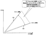
ところが、近年の装置の大型化、プロセス圧力/流量の広範囲化にともない、真空装置に複数台のポンプを設置する構成が必要とされ、検討が行われている。同じポンプを複数台設置し、連動して動作させた場合、圧力及び流量を制御できない領域がある。例えば、横軸はガス流量、縦軸は圧力を示した図24を参照すると、この場合、真空装置に装着された排気系は4ラインであり、すべてが連動して同時に動作するようになっている。排気装置では、ポンプ及び圧力制御バルブの開度の変化によりコンダクタンスが変化する。このため、圧力制御バルブが制御可能な開度の範囲に応じて、圧力制御が可能な範囲が自ずと決まる。例えば、図24では、一般的な真空装置の場合であって、4ラインの排気系がすべてが連動して動作する場合、装置内部の圧力制御できる範囲は、ガス流量との関係で、点線で示した三角形の領域内に限られてしまい、圧力及び流量を制御できない領域があることを発明者は発見した。
これに対して、特許文献1では、荒引きポンプにつながるラインと、高真空ポンプのつながるラインの二つのラインを設け、目標圧力に応じて異なるポンプのいずれかを選択して、ライン(ポンプ)を切り替える制御方法が開示されているが、同じ種類のポンプを並列に接続するような構成にはなっていない。
かかる課題を解決するために、本発明は、真空装置に対してそれぞれが並列に配置された複数の排気装置を用いてより広範囲な圧力制御及びガス流量制御が可能な排気装置の制御方法及び排気装置の制御装置を提供することを目的とする。
上記課題を解決するために、本発明のある観点によれば、真空装置に設けられた複数の排気装置の制御方法であって、前記真空装置に導入するガスの流量が少なくなるほど、連動して制御する排気装置の数を減らし、非連動に制御する排気装置の数を増やすように前記複数の排気装置の連動又は非連動の状態を設定する設定工程と、前記設定された状態で、前記複数の排気装置のうちの少なくともいずれかを使用して前記真空装置を排気する排気工程と、を含む排気装置の制御方法が提供される。
また、上記課題を解決するために、本発明の他の観点によれば、真空装置に設けられた複数の排気装置の制御方法であって、前記真空装置内の圧力が高くなるほど、各排気装置に連動して制御する排気装置の数を減らし、非連動に制御する排気装置の数を増やすように前記複数の排気装置の連動又は非連動の状態を設定する設定工程と、前記設定された状態で、前記複数の排気装置のうちの少なくともいずれかを使用して前記真空装置を排気する排気工程と、を含む排気装置の制御方法が提供される。
これによれば、真空装置に導入するガスの流量が少なくなるほど、連動して制御する排気装置の数を減らし、非連動に制御する排気装置の数を増やすように前記複数の排気装置の連動又は非連動の状態を設定する。また、前記真空装置内の圧力が高くなるほど、各排気装置に連動して制御する排気装置の数を減らし、非連動に制御する排気装置の数を増やすように前記複数の排気装置の連動又は非連動の状態を設定する。
図1によれば、4ラインの排気系を連動して動作させる場合と、1ラインの排気系を単独で動作させる場合とでは、制御可能な圧力帯が異なる。たとえば、図1の三角形の領域は、4ラインの排気系を連動して動作させる場合には制御できない範囲であるが、1ラインの排気系を単独で動作させる場合には制御できる範囲である。したがって、排気装置の連動、非連動の設定を変えることにより、ガスの流量変化に対応して制御可能な圧力帯を広くすることができ、真空容器内の圧力の変動を抑えることができる。低真空から高真空まで広範囲に圧力制御を行う必要があるプロセスであっても、制御可能な圧力帯を広くすることができるため、真空容器内の圧力の変動を抑えることができる。
また、上記課題を解決するために、本発明の他の観点によれば、一つの真空室に並列に接続され、前記真空室内の空間を真空排気する複数の排気装置を備えた真空装置の制御方法であって、前記真空室の目標圧力が複数の圧力帯のいずれに属するかで、連通して制御する前記排気装置の数を決定する工程と、前記連通した排気装置と前記真空室との間に設けた弁体の開口度は可変で制御し、前記連通した以外の非連通の排気装置と前記真空室との間に設けた弁体の開口度は固定して制御する工程と、を備えた真空装置の制御方法が提供される。
また、上記課題を解決するために、本発明の他の観点によれば、一つの真空室に並列に接続され、前記真空室内の空間を真空排気する複数の排気装置を備えた真空装置の制御方法であって、前記真空室の目標流量が複数の流量帯のいずれに属するかで、連通して制御する前記排気装置の数を決定する工程と、前記連通した排気装置と前記真空室との間に設けた弁体の開口度は可変で制御し、前記連通した以外の非連通の排気装置と前記真空室との間に設けた弁体の開口度は固定して制御する工程と、を備えた真空装置の制御方法が提供される。
また、上記課題を解決するために、本発明の他の観点によれば、真空装置に設けられた複数の排気装置の制御装置であって、前記真空装置に導入するガスの流量が少なくなるほど、連動して制御する排気装置の数を減らし、非連動に制御する排気装置の数を増やすように前記複数の排気装置の連動又は非連動の状態を設定する設定制御部と、前記設定された状態で、前記複数の排気装置のうちの少なくともいずれかを使用して前記真空装置を排気する排気制御部と、を備える排気装置の制御装置が提供される。
以上説明したように、本発明によれば、ガスの流量の変化が広範囲であっても、広範囲の圧力制御が可能である。
以下に添付図面を参照しながら、本発明の好適な実施形態について詳細に説明する。なお、以下の説明及び添付図面において、同一の構成及び機能を有する構成要素については、同一符号を付することにより、重複説明を省略する。
まず、本発明の第1及び第2実施形態に係る真空装置に適用される圧力制御の原理について、図1~図5を参照しながら説明する。その後、各実施形態について説明する。
以下の説明では、図6に示したシャットオフバルブ及び圧力制御バルブは、シャットオフ機能を備えたバルブの他の一例であり、図12に示したAPCバルブも、シャットオフ機能を備えたバルブの一例である。APCバルブはシャットオフバルブと圧力制御バルブとが一体化したものである。
また、以下の説明では、「連動」とは、例えば、図13に示したマスタのシャットオフ機能を備えたバルブに対して、マスタに数珠繋ぎになったスレーブのシャットオフ機能を備えたバルブが連動して動作することをいう。また、「非連動」とは、マスタのシャットオフ機能を備えたバルブに対して、マスタに数珠繋ぎになったスレーブのシャットオフ機能を備えたバルブが連動して動作しないことをいう。「非連動」の場合、バルブの開度を他のバルブの動作とは非連動に所定の開度に固定させて動作させる「開度制御(非連動)」状態、バルブの開度を他のバルブの動作とは非連動に最大開度に固定させて動作させる「フルオープン(非連動)」状態、バルブの開度を他のバルブの開度とは非連動に最小開度に固定させて動作させる「フルクローズ(非連動)」状態がある。
(圧力制御の原理)
排気系に設けられている圧力制御バルブは、構造上、制御できる圧力帯がある程度制限される。例えば、図6に示したように、ある真空装置に装備されている排気装置(真空排気装置)がA,B,C,Dの4つの場合、4つの排気装置を連動してすべて同じ開度で動作させると、圧力制御バルブの稼動可能な開度の幅によって使用可能な圧力帯が限定される。例えば、図24では、4つの排気装置の圧力制御バルブを最も閉じたときの圧力制御ラインSCと、圧力制御バルブを最も開いたときの圧力制御ラインSOとの間の三角地帯が圧力及び流量制御可能領域となっている。
排気系に設けられている圧力制御バルブは、構造上、制御できる圧力帯がある程度制限される。例えば、図6に示したように、ある真空装置に装備されている排気装置(真空排気装置)がA,B,C,Dの4つの場合、4つの排気装置を連動してすべて同じ開度で動作させると、圧力制御バルブの稼動可能な開度の幅によって使用可能な圧力帯が限定される。例えば、図24では、4つの排気装置の圧力制御バルブを最も閉じたときの圧力制御ラインSCと、圧力制御バルブを最も開いたときの圧力制御ラインSOとの間の三角地帯が圧力及び流量制御可能領域となっている。
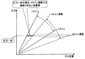
これに対して、図1に示したように、4つの排気装置のうち1つの排気装置のみ非連動で動作させた場合、4つの排気装置を連動させて同時に動作させた場合に比べて、排気能力は1/4になる。このとき、連動で制御される4つの排気装置と、非連動で制御される1つの排気装置の圧力制御バルブの開度は同じである。このように、1つの排気装置を非連動で制御すると、4つの排気装置を連動制御した場合に制御できない領域Qにおいても、圧力制御及び流量制御を行うことができる。
例えば、図2に示したように、1つの排気装置を非連動で動作させた場合であってガス流量を一定に制御した場合、4つの排気装置を連動させて動作させた場合には制御できなかった、より高い圧力帯において圧力制御を行うことができる。また、図3に示したように、1つ排気装置を非連動で動作させた場合であって圧力を一定に制御した場合、4つの排気装置を連動させて動作させた場合には制御できなかった、より少ないガスの流量帯においてガス流量の制御を行うことができる。
次に、所定の圧力及びガス流量のときに最適な排気装置の連動、非連動の設定方法について、図4を参照しながら説明する。例えば、圧力及びガス流量が点C1になるようにプロセス条件が設定されている場合、4つの排気装置を連動させて同時に動作させるように各排気装置を設定してもよいし、6つの排気装置を連動させて同時に動作させるように各排気装置を設定してもよい。一方、例えば、圧力及びガス流量が点C2になるようにプロセス条件が設定されている場合、6つの排気装置を連動させて同時に動作させるように各排気装置を設定する。
また、例えば、圧力及びガス流量が点C3になるようにプロセス条件が設定されている場合、2つの排気装置を連動させるか、4つの排気装置を連動させるか、6つの排気装置を連動させて動作させるように各排気装置を設定することができる。一方、例えば、圧力及びガス流量が点C4になるようにプロセス条件が設定されている場合、4つの排気装置を連動させるか、6つの排気装置を連動させて動作させるように各排気装置を設定することができる。ただし、なるべくプロセス条件の点がラインの境界に位置しない排気制御が好ましい。
また、例えば、圧力及びガス流量が点C5になるようにプロセス条件が設定されている場合、2つの排気装置を連動させて動作させるように各排気装置を設定することができる。一方、圧力及びガス流量が点C6になるようにプロセス条件が設定されている場合、2つの排気装置を連動させるか、4つの排気装置を連動させて動作させるように各排気装置を設定することができる。
以上から、真空装置に設けられた複数の排気装置に対して、本実施形態に係る排気装置の制御方法では、設定工程にて、真空装置に導入するガスの流量が少なくなるほど、連動して制御する排気装置の数を減らし、非連動に制御する排気装置の数を増やすように前記複数の排気装置の連動又は非連動の状態を設定すると、より広い範囲で圧力及びガス流量を制御することができる。排気工程では、前記設定された状態で前記複数の排気装置のうちの少なくともいずれかを使用して前記真空装置を排気する。これにより、真空装置内部を所定の圧力に保持することができる。
また、真空装置に設けられた複数の排気装置に対して、本実施形態に係る排気装置の制御方法では、設定工程にて、真空装置内の圧力が高くなるほど、各排気装置に連動して制御する排気装置の数を減らし、非連動に制御する排気装置の数を増やすように前記複数の排気装置の連動又は非連動の状態を設定する。排気工程では、前記設定された状態で前記複数の排気装置のうちの少なくともいずれかを使用して前記真空装置を排気する。これによっても、より広い範囲で圧力及びガス流量を制御することができる。
このようにして、排気装置の連動、非連動の設定をプロセス条件に応じて変化させることにより、変化させない場合に比べて広範囲な圧力及びガス流量の制御ができる。例えば、図4の点C5、点C6は、6ラインの排気系が連動して動作する場合には制御できない圧力帯であったが、2ライン又は4ラインの連動制御に設定変更することにより制御可能な圧力帯となる。このように、制御したいガス流量及び制御したい圧力に応じて排気装置の連動、非連動の設定を変えることにより、真空容器内の圧力の変動を抑えながら、ガスの流量を広範囲に変動させることができる。
図5は、真空装置を上から平面視した図である。図5(a)は真空装置に10台の排気装置が装備されている場合、図5(b)は真空装置に4台の排気装置が装備されている場合の各排気装置の設定例を示す。ここでは、排気装置の弁体として、APC(Automatic Pressure Control)バルブが装着されている。
図5では、APCバルブを4種類の状態のいずれかに設定する。1つ目の状態は、「圧力制御(連動)」、つまり、特定された所定個のAPCバルブの開度を連動して同時に変化させながら動作させる状態である。2つ目の状態は、「開度制御(非連動)」、つまり、APCバルブの開度を他の排気装置のAPCバルブの開度とは非連動に所定の開度に固定させて動作させる状態である。3つ目の状態は、「フルオープン(非連動)」、つまり、APCバルブの開度を他の排気装置のAPCバルブの開度とは非連動に最大開度に固定させて動作させる状態である。4つ目の状態は、「フルクローズ(非連動)」、つまり、APCバルブの開度を他の排気装置のAPCバルブの開度とは非連動に最小開度に固定させて動作させる状態である。
なお、APCバルブを4種類の状態のいずれかに設定するタイミングについて言及すると、本実施形態に係る設定工程では、複数の排気装置のAPCバルブの連動又は非連動の状態を、真空装置で実行される各プロセスに応じて各プロセスが開始される前に動的に変化させてもよい。
また、本実施形態に係る設定工程は、前記複数の排気装置の連動又は非連動の状態を、各プロセスが開始される前に設定される状態から、前記真空装置で実行される各プロセスに応じて前記各プロセス中に動的に変化させてもよい。
図5(a1)は、すべてのAPCバルブが連動して動作するように、すべてのAPCバルブを「圧力制御(連動)」に設定した場合である。このように、すべてのAPCバルブが連動して同時に動作すると、装置内部の圧力制御が比較的限られた領域に制限されてしまうため、広範囲なガス流量の変動に対応できず、真空装置の内部の圧力が変動してしまい、プロセスに悪い影響を与えてしまう場合がある。また、低真空から高真空まで広範囲な圧力制御が必要なプロセスに対応できずに圧力が変動してしまい、プロセスに悪い影響を与えてしまう場合がある。
図5(a2)では、「圧力制御(連動)」に設定されたAPCバルブと「開度制御(非連動)」に設定されたAPCバルブとが互い違い配置されている。図5(a3)では、「圧力制御(連動)」に設定されたAPCバルブと「フルクローズ(非連動)」に設定されたAPCバルブとが互い違い配置されている。図5(a4)では、「圧力制御(連動)」に設定されたAPCバルブと「フルオープン(非連動)」に設定されたAPCバルブとが互い違い配置されている。
図5(a5)では、両端及び中央の位置にて「圧力制御(連動)」に設定された3つのAPCバルブと、その間に「フルクローズ(非連動)」に設定された7つのAPCバルブとが配置されている。図5(a6)では、「圧力制御(連動)」に設定され、2つずつ3列に並んだAPCバルブと、その間に「開度制御(非連動)」に設定されたAPCバルブとがストライプ状に配置されている。
図5(a7)では、「圧力制御(連動)」に設定され、2つずつ並んだAPCバルブが両端に設けられ、その間に「開度制御(非連動)」に設定されたAPCバルブが6つ配置されている。図5(a8)では、「圧力制御(連動)」に設定され、2つずつ並んだAPCバルブが両端に設けられ、その間に「フルクローズ(非連動)」に設定されたAPCバルブが6つ配置されている。
図5(b1)は、すべてのAPCバルブが連動して動作するように、すべてのAPCバルブを「圧力制御(連動)」に設定した場合である。図5(b2)では、「圧力制御(連動)」に設定されたAPCバルブが両端に設けられ、その間に「開度制御(非連動)」に設定されたAPCバルブが2つ配置されている。図5(b3)では、「圧力制御(連動)」に設定されたAPCバルブが両端に設けられ、その間に「フルクローズ(非連動)」に設定されたAPCバルブが2つ配置されている。図5(b4)では、「開度制御(非連動)」に設定されたAPCバルブが両端に設けられ、その間に「圧力制御(連動)」に設定されたAPCバルブが2つ配置されている。図5(b5)では、「フルクローズ(非連動)」に設定されたAPCバルブが両端に設けられ、その間に「圧力制御(連動)」に設定されたAPCバルブが2つ配置されている。
このように、APCバルブの設定方法をプロセスに応じて最適化することにより、圧力制御可能範囲及びガス流量制御可能範囲を広くすることができ、真空装置内の排気状態を良好に制御することができる。例えば、ガスの吹き溜まりが生じないようにするために、真空装置の外側の排気を強くしたり、排気装置を交互に強弱をつけることにより真空装置全体も均一に排気したり等、異なる設定の組合せを考えることができる。
(第1実施形態)
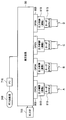
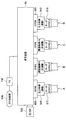
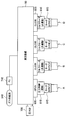
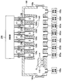
以下では、本発明の第1実施形態に係る真空装置について、図6を参照しながら説明する。図6は、第1実施形態に係る真空装置50の概略構成図である。第1実施形態では、弁体はシャットオフバルブ805及び圧力制御バルブ810を含み、真空装置50の排気側に配置されている。本実施形態の排気系A~Dは4ラインであり、シャットオフバルブ805と圧力制御バルブ810とが別体になっている。排気系A~Dには、ターボ分子ポンプ815が設けられている。ターボ分子ポンプ815は、図示しないドライポンプと排気配管を介して連結されている。ドライポンプは、真空装置50の内部を荒引きし、ターボ分子ポンプ815は、処理室内部を真空引きする。これにより、処理室内部は所定の真空度に保持される。なお、高真空ポンプは、ターボ分子ポンプに限られず、クライオポンプやクライオトラップなどを使用することもできる。
以下では、本発明の第1実施形態に係る真空装置について、図6を参照しながら説明する。図6は、第1実施形態に係る真空装置50の概略構成図である。第1実施形態では、弁体はシャットオフバルブ805及び圧力制御バルブ810を含み、真空装置50の排気側に配置されている。本実施形態の排気系A~Dは4ラインであり、シャットオフバルブ805と圧力制御バルブ810とが別体になっている。排気系A~Dには、ターボ分子ポンプ815が設けられている。ターボ分子ポンプ815は、図示しないドライポンプと排気配管を介して連結されている。ドライポンプは、真空装置50の内部を荒引きし、ターボ分子ポンプ815は、処理室内部を真空引きする。これにより、処理室内部は所定の真空度に保持される。なお、高真空ポンプは、ターボ分子ポンプに限られず、クライオポンプやクライオトラップなどを使用することもできる。
また、各弁体は並列に配置されている。圧力制御バルブ810は、シャットオフバルブ805に対して連動モードと非連動モードとを有している。圧力計705は、真空装置50内の圧力を圧力モニター値として検出し、当該圧力モニター値を装置コントローラ900に出力する。装置コントローラ900は、圧力モニター値に基づき制御信号を生成する。生成された制御信号は、圧力制御バルブ810に送られる。圧力制御バルブ810の開度は制御信号に基づき装置コントローラ900により制御されている。これによって、真空装置50内がターゲット圧力値になるように制御される。装置コントローラ900により制御されている。これにより真空装置50内を圧力制御することができる。
かかる構成の真空装置50では、4ラインの排気系A~Dにて圧力制御が行われる。図6に示されているように、本実施形態では、真空装置50は気密な真空処理室で構成されており、処理室内部の空間を排気する4ラインの排気系A~Dが、前記処理室の底面に並列して配置された排気口を介して接続されている。かかる構成により、排気系A~Dのそれぞれは他の排気系を介することなく、また他の排気系と排気のラインを共用することなく、直接に前記処理室内部を排気することが可能な構成となっている。更に、真空処理室の底部から排気することによりゴミを巻き上げることの少ない構成となっている。図7では、すべての圧力制御バルブ810が「圧力制御(連動)」に設定され、すべてのシャットオフバルブ805は開かれている。かかる設定により、圧力発振を抑えるために、4つの圧力制御バルブは圧力制御バルブ810の開度がすべて同じ大きさで変動するよう連動して動作する。大流量のガスを導入する場合に適している。
図8では、中央の2つの圧力制御バルブ810が「圧力制御(連動)」に設定され、両側の2つの圧力制御バルブ810が「フルクローズ(非連動)」に設定されている。シャットオフバルブ805についても、中央の2つは開かれていて、両側の2つは閉じている。かかる設定により、中央の2つの排気系B、Cにて圧力制御を行う。圧力発振を抑えるために、中央の2つの圧力制御バルブは開度をすべて同じ大きさに変動させながら連動して動作する。この場合、両側の2つの圧力制御バルブ810は、圧力制御の連動制御の対象外となる。中流量のガスを導入する場合に適している。
図9では、両側の2つの圧力制御バルブ810が「圧力制御(連動)」に設定され、中央の2つの圧力制御バルブ810が「開度制御1%(非連動)」に設定されている。シャットオフバルブ805については、すべて開かれている。かかる設定では、中央の2つの圧力制御バルブ81を完全に閉めるのではなく若干空けて(ここでは開度制御1%で固定して)制御する。これにより、真空装置50内のゴミの滞留を抑止し、気流の状態を良好にすることができる。中流量のガスを導入する場合に適している。
図10では、左端の1つの圧力制御バルブ810のみが「圧力制御(連動)」に設定され、右側の3つの圧力制御バルブ810が「フルクローズ(非連動)」に設定されている。シャットオフバルブ805についても、左端の1つは開かれていて、右側の3つは閉じている。小流量のガスを導入する場合に適している。すなわち、小流量のガスを導入するときには、排気能力を下げて圧力を一定にしたい。そのため、外側1つだけ開けて圧力制御する。例えば、図1の4ライン連動では圧力制御できない範囲Qで安定的に圧力制御することが可能になる。プロセス圧力帯とガス流量の値により、連動して圧力制御する圧力制御バルブ810を1つにしたり、2つにしたりと動的に変更して、排気装置の使用台数を選択可能にしてもよい。
図11では、左端の1つの圧力制御バルブ810のみが「圧力制御(連動)」に設定され、右側の3つの圧力制御バルブ810が「開度制御1%(非連動)」に設定されている。シャットオフバルブ805については、すべて開かれている。小流量のガスを導入する場合に適している。この場合にも、小流量のガスを流しながら排気能力を下げて圧力を一定にするために、左端の1つの圧力制御バルブ810のみで圧力制御する。すなわち、図1の4ライン連動では圧力制御できない範囲Qで圧力制御が可能になる。右側の3つの圧力制御バルブ810を少しだけ開けておくのは、ゴミや吹き溜まりをなくすためである。プロセス圧力帯とガス流量の値により、連動して圧力制御する圧力制御バルブ810を1つにしたり、2つにしたりと動的に変更して、排気装置の使用台数を選択可能にしてもよい。なお、右側の3つの圧力制御バルブ810の開度制御は1~10%が適している。
(第2実施形態)
次に、本発明の第2実施形態に係る真空装置について、図12を参照しながら説明する。図12は、第2実施形態に係る真空装置50の概略構成図である。第2実施形態の排気系A~Dは4ラインであり、APCバルブ820が、第1実施形態で示したシャットオフバルブ805及び圧力制御バルブ810の替わりに装備されている。APCバルブ820は、真空装置50の排気側に配置されている。排気系A~Dには、ターボ分子ポンプ815が設けられている。ターボ分子ポンプ815は、図示しないドライポンプと排気配管を介して連結されている。ドライポンプは、真空装置50(処理室又は真空室)内を荒引きし、ターボ分子ポンプ815は、真空装置50内部を高い真空度まで真空引き可能である。これらにより、処理室内部は所定の真空度に保持される。
次に、本発明の第2実施形態に係る真空装置について、図12を参照しながら説明する。図12は、第2実施形態に係る真空装置50の概略構成図である。第2実施形態の排気系A~Dは4ラインであり、APCバルブ820が、第1実施形態で示したシャットオフバルブ805及び圧力制御バルブ810の替わりに装備されている。APCバルブ820は、真空装置50の排気側に配置されている。排気系A~Dには、ターボ分子ポンプ815が設けられている。ターボ分子ポンプ815は、図示しないドライポンプと排気配管を介して連結されている。ドライポンプは、真空装置50(処理室又は真空室)内を荒引きし、ターボ分子ポンプ815は、真空装置50内部を高い真空度まで真空引き可能である。これらにより、処理室内部は所定の真空度に保持される。
圧力計705は、随時真空装置50内の圧力を検出し、圧力モニター値を出力する。真空装置50(処理室)は、圧力モニター値に基づき、ガス流量制御装置710により制御されるガス流量に応じてその内部がターゲット圧力値になるようにAPCバルブの開度を制御する。これにより真空装置50内を圧力制御することができる。
以上に説明したいずれの実施形態に置いても、バルブの設定方法をプロセスに応じて最適化することにより、圧力制御可能範囲及びガス流量制御可能範囲を広くすることができ、真空装置50内の排気状態を良好にすることができる。
(インターロック制御)
以下では、第1及び第2実施形態に係る真空装置50(処理室)を形成する装置の一例として、基板を処理する基板処理装置の場合を例に挙げて説明する。上記排気装置の連動、非連動の設定を最適化し、真空装置50の圧力を安定的に制御したとしても、基板処理装置が異常状態である場合、真空装置50内を所望の圧力に保持できなくなったりして、基板に所望の処理が施せなくなる。そこで、従来から、インターロック装置を用いて機器の誤動作を防止する仕組みが考えられている。インターロック装置は、真空装置内のゲートバルブやポンプ等の各機器の状態を検知するセンサからの信号を入力し、入力した信号が所与のインターロック条件を満たす場合、異常事態と判断して機器の誤動作を回避するためのインターロック信号を出力する。該当機器は、インターロック信号の指示に従い動作を停止する。インターロック装置は、上記機能を有するインターロック制御回路を有している。
以下では、第1及び第2実施形態に係る真空装置50(処理室)を形成する装置の一例として、基板を処理する基板処理装置の場合を例に挙げて説明する。上記排気装置の連動、非連動の設定を最適化し、真空装置50の圧力を安定的に制御したとしても、基板処理装置が異常状態である場合、真空装置50内を所望の圧力に保持できなくなったりして、基板に所望の処理が施せなくなる。そこで、従来から、インターロック装置を用いて機器の誤動作を防止する仕組みが考えられている。インターロック装置は、真空装置内のゲートバルブやポンプ等の各機器の状態を検知するセンサからの信号を入力し、入力した信号が所与のインターロック条件を満たす場合、異常事態と判断して機器の誤動作を回避するためのインターロック信号を出力する。該当機器は、インターロック信号の指示に従い動作を停止する。インターロック装置は、上記機能を有するインターロック制御回路を有している。
制御信号に対するシャットオフ機能を備えたバルブの連動、非連動制御は、インターロック信号に対しても同様に行われる。つまり、連動と選択された複数のシャットオフ機能を備えたバルブは、インターロック制御装置から出力されたインターロック信号に応じて制御されるが、非連動と選択されたバルブは、インターロック信号に応じず、現状を維持する。これでは、インターロック制御装置からの指示に従って事故を回避したい緊急時であっても、非連動のバルブをインターロック信号に基づき強制的に動作させることができないことになる。このようにインターロック機能が不十分であると、安全面からの迅速な対応が妨げられ、システムが危険な状態になるおそれがある。たとえば、使用可能な圧力を逸脱した状態でターボ分子ポンプを使用し、ポンプの破損や寿命の低下、システムダウンが発生すると、装置の緊急メンテナンスが必要となり生産性が落ちるだけでなくシステム管理者の負担も大きくなる。
そこで、以下では、インターロック制御装置が異常を発信した場合、連動又は非連動にかかわらず、インターロック信号に基づき複数の排気装置をクラスタ制御する方法を説明する。
なお、第1実施形態の圧力制御バルブ810のうち隣接する機器同士は、Ethernet(登録商標)等のネットワークにより接続されている。第2実施形態のAPCバルブ820も同様に、APCバルブ820のうち隣接する機器同士は、Ethernet(登録商標)等のネットワークにより接続されている。
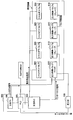
図13は、シャットオフバルブ805と圧力制御バルブ810とが別体の場合の信号入力の一例を示す。圧力計705は、真空装置50内の圧力を圧力モニター値として検出し、当該圧力モニター値を装置コントローラ900に出力する。装置コントローラ900は、圧力モニター値に基づき制御信号を生成する。生成された制御信号は、圧力制御バルブ1に送られる。圧力制御バルブ810の開度は制御信号に基づき装置コントローラ900により制御されている。これによって、真空装置50内がターゲット圧力値になるように制御される。この場合、図13にて示したマスタ側の圧力制御バルブ1で圧力の調整値が決定される。スレーブ側の圧力制御バルブ2、3、4は、圧力制御バルブ1から指示された開度に圧力制御バルブ2,3,4の開度調整をそれぞれ行う。このようにして、圧力制御バルブ1に追従して圧力制御バルブ2、3、4を圧力制御することにより、バルブ間の開度や制御のずれがなく圧力の発振を抑えることができる。これにより真空装置50内を所望の圧力に安定して制御できる。
図13は、シャットオフバルブ805と圧力制御バルブ810とが別体の場合の信号入力の一例を示す。この場合、シリアル信号及び圧力モニター値は、装置コントローラ900から圧力制御バルブ1にのみ送られる。装置コントローラ900は、上位のコントローラである上位PCや下位のコントローラであるPLCを含み、制御信号としてシリアル信号を送出する。
安全PLC300は、4つの排気系のシャットオフバルブ1~4にフルオープン、開度制御、フルクローズを指示するための動作指示信号を送出する。シャットオフバルブ1~4は、動作指示信号に基づきそれぞれ開閉する。
インターロック発生条件が成立したときには、圧力制御バルブにフルクローズを指示するためのインターロック信号を送出する。図13では、インターロック信号は、マスタ側の圧力制御バルブ1のみに入力される。この場合、マスタ側の圧力制御バルブ1は、インターロック信号に基づき圧力制御バルブ1をフルクローズするとともに、インターロック信号をスレーブ側の圧力制御バルブ2~4に転送して圧力制御バルブ2~4をフルクローズさせる。
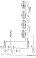
図14は、シャットオフバルブ805と圧力制御バルブ810とが別体の場合の信号入力の他の例を示す。この場合にも、シリアル信号及び圧力モニター値は、圧力制御バルブ1にのみ送られる。一方、動作指示信号はすべてのシャットオフバルブ1~4に送られる。また、インターロック信号は、すべての圧力制御バルブ1~4に送られ、圧力制御バルブ1~4をそれぞれフルクローズさせる。インターロック信号は、シャットオフバルブ1~4にも送られ、シャットオフバルブ1~4をそれぞれフルクローズさせる。
インターロック発生条件が成立したときには、シャットオフバルブ1~4と圧力制御バルブ1~4との両方を閉める方がシャットオフバルブ1~4及び圧力制御バルブ1~4の次の動作時を考慮すると好ましい。しかし、インターロック発生時、シャットオフバルブ1~4をフルクローズするだけの安全処理で対応してもよいし、圧力制御バルブ1~4をフルクローズするだけの安全処理で対応してもよい。
なお、圧力制御バルブ810の機能としては、(1)フルクローズ(全閉)の状態のまま動かない場合(非連動)、(2)フルオープン(全開)の状態のまま動かない場合(非連動)、(3)開度制御し、ある一定の開度で固定する場合(非連動)、(4)圧力制御し、圧力計を見て圧力を一定に保つように自動でバルブの開閉をする場合(連動)の4つのパターンがある。インターロック発生時には、圧力制御バルブ1~4の連動/非連動にかかわらず、全ての圧力制御バルブ1~4をインターロック信号に従いフルクローズする。
前述の通り、圧力制御バルブ810の4つの機能は、たとえば、複数の圧力制御バルブ810のうちの一部の圧力制御バルブ810をフルオープンにし、残りの圧力制御バルブ810を圧力制御する場合や、複数の圧力制御バルブ810のうちの一部の圧力制御バルブ810を開度制御1%等に固定し、残りの圧力制御バルブ810を圧力制御する場合や、複数の圧力制御バルブ810のうちの一部の圧力制御バルブ810をフルクローズにし、残りの圧力制御バルブ810を圧力制御する場合等いろいろな組み合わせが考えられる。なお、圧力制御バルブ810をフルクローズせずに開度制御1%等に固定することにより、ごみの滞留やシール部の固着を防止することが可能となる。
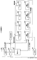
図15は、シャットオフバルブと圧力制御バルブとが一体化した場合(APCバルブの場合)のインターロック信号の入力の一例を示した図である。図16は、APCバルブの場合のインターロック信号の入力の他の例を示した図である。
インターロック発生条件が成立したときには、インターロック信号線は、図15に示したようにそれぞれのAPCバルブに数珠繋ぎとなるように接続されてもよく、図16に示したようにそれぞれのAPCバルブにそれぞれ接続されてもよい。図15に示したAPCバルブは、マスタ側のAPC1とスレーブ側のAPC2~APC4が連動して制御される。
(大流量時)
以下の説明では、図17~図20を参照しながら、図13に示したシャットオフバルブ及び圧力制御バルブを用いた装置形態の制御について説明し、図21及び図22を参照しながら、図15に示したAPCバルブを用いた装置形態の制御について説明する。
以下の説明では、図17~図20を参照しながら、図13に示したシャットオフバルブ及び圧力制御バルブを用いた装置形態の制御について説明し、図21及び図22を参照しながら、図15に示したAPCバルブを用いた装置形態の制御について説明する。
たとえば、大流量時の運用例を図17に示す。大流量時には、設置されているすべてのシャットオフバルブ805及び圧力制御バルブ810を用いて連動して圧力制御する。すなわち、大流量時には、シャットオフバルブ805はすべてフルオープンしていて、圧力制御バルブ810は圧力計705の圧力モニター値に基づき、真空装置50内が圧力ターゲット値になるようにすべての圧力制御バルブ810の開度を調整することにより圧力制御を行う。
インターロック発生条件が成立したときには、フルクローズのインターロック信号がマスタ側の圧力制御バルブ810に入力され、マスタ側の圧力制御バルブ810の開度を全閉させるとともに、マスタ側の圧力制御バルブ810から3つのスレーブ側の圧力制御バルブ810に全閉を指示する信号を送ることにより、連動する3つのスレーブ側の圧力制御バルブ810の開度を全閉させる。また、フルクローズの動作指示信号がすべてのシャットオフバルブ805に入力され、すべてのシャットオフバルブ805を閉状態にさせる。これにより、大流量時には、通常状態では、すべてのシャットオフバルブ805及び圧力制御バルブ810をフルオープンにして真空装置50を圧力制御し、インターロック発生条件が成立したときにはすべてのシャットオフバルブ805及び圧力制御バルブ810を全閉状態にして動作を強制終了する。なお、インターロック発生時、圧力制御バルブ810のみにインターロック信号が入力され、シャットオフバルブ805にインターロック信号が入力されない場合にはシャットオフバルブ805は開状態のままとなる。
(中流量時)
中流量時の運用例としては図18に示したように、設置されている圧力制御バルブ810のうち、一部は連動して圧力制御し、残りは非連動にしてたとえば開度制御1%に固定する。通常動作時には、動作指示信号に従い全てのシャットオフバルブ805が開状態になっている。
中流量時の運用例としては図18に示したように、設置されている圧力制御バルブ810のうち、一部は連動して圧力制御し、残りは非連動にしてたとえば開度制御1%に固定する。通常動作時には、動作指示信号に従い全てのシャットオフバルブ805が開状態になっている。
この場合、図18の破線領域Nにて示した圧力制御バルブ810は、それ以外の圧力制御バルブ810と連動して動作していない。しかしながら、インターロック発生条件が成立したときには破線領域Nにて示した圧力制御バルブ810も残りの圧力制御バルブ810に連動して安全処理(フルクローズ)する必要がある。
そこで、インターロック発生条件が成立したときには、圧力制御中の2つの圧力制御バルブ810を、フルクローズのインターロック信号に応じて全閉状態にし、開度制御1%に固定した非連動の2つの圧力制御バルブ810もマスタ側の圧力制御バルブ810の指示に従い強制的に全閉状態にして動作を強制終了する。
なお、インターロック発生条件時、圧力制御バルブ810にインターロック信号を送らずに、フルクローズのインターロック信号(動作指示信号)を全シャットオフバルブ805に送り、全シャットオフバルブ805をフルクローズさせるようにしてもよい。ただし、次動作や安全面を考慮すると、前述したように圧力制御バルブ810を全閉状態にし、更に全シャットオフバルブ805もフルクローズさせるほうが好ましいし、少なくとも圧力制御バルブ810だけは強制的に全閉状態にしたほうがよい。
(小流量時)
小流量時の運用例としては図19に示したように、設置されている圧力制御バルブ810のうち、中流量時よりさらに少ない1つの圧力制御バルブ810のみを圧力制御し、残りの3台は非連動にしてたとえば開度制御1%に固定する。通常動作時には、動作指示信号に従いすべてのシャットオフバルブ805は開状態になっている。
小流量時の運用例としては図19に示したように、設置されている圧力制御バルブ810のうち、中流量時よりさらに少ない1つの圧力制御バルブ810のみを圧力制御し、残りの3台は非連動にしてたとえば開度制御1%に固定する。通常動作時には、動作指示信号に従いすべてのシャットオフバルブ805は開状態になっている。
この場合、図19の破線領域Nにて示した圧力制御バルブ810は、それ以外の圧力制御バルブ810と連動して動作していない。しかしながら、小流量時にもインターロック発生条件が成立したときには破線領域Nにて示した圧力制御バルブ810を安全処理する必要がある。
そこで、インターロック発生条件が成立したときには、図20に示したように、圧力制御中のマスタ側の圧力制御バルブ810を、フルクローズのインターロック信号に応じて全閉状態にし、開度制御1%に固定した非連動の3つの圧力制御バルブ810もマスタ側の圧力制御バルブ810の指示に従い強制的に全閉状態にして動作を強制終了する。
以上、シャットオフバルブ805と圧力制御バルブ810とが別体の場合の安全処理について説明した。これによれば、大流量時、中流量時、小流量時の場合に圧力制御バルブ810に稼働条件の違いがあってもインターロック発生条件が成立したときにはすべての圧力制御バルブ810を安全処理することができる。
なお、一体の場合(APCバルブの場合)の大流量時、中流量時、小流量時の安全処理は別体の場合の安全処理と基本的に同じである。たとえば、APCバルブの場合、小流量時、図21に示したように、2つのAPC1及びAPC2は連動して圧力制御し、残りのAPC3及びAPC4は非連動にしてたとえば全閉状態に固定する。
小流量時、図22に示したように、2つのAPC1及びAPC2は連動して圧力制御し、残りは非連動にしてたとえば開度制御1%に固定するようにしてもよい。この場合、図22の破線領域Nにて示したAPC3及びAPC4は、APC1及びAPC2と連動して動作していない。しかしながら、インターロック発生条件が成立したときには破線領域Nにて示したAPCバルブを安全処理する必要がある。
そこで、インターロック発生条件が成立したときには、連動するAPC1及びAPC2をフルクローズのインターロック信号に応じて全閉状態にするだけでなく、非連動のAPC3及びAPC4も全閉状態にして動作を強制終了する。
以上、各実施形態に係るシステムよれば、インターロック制御装置が異常を発信した場合、連動又は非連動にかかわらずインターロック信号に基づき同種の複数の排気装置を制御することができる。これにより、安全処理を滞りなく行うことができる。
なお、以上の説明では、図17~図20を参照しながら、図13のシャットオフバルブ及び圧力制御バルブを用いた装置形態の制御について説明したが、この制御は、図14のインターロック信号が各バルブへ入力される場合の装置形態にも適用可能である。同様に、図21及び図22を参照しながら、図15のAPCバルブを用いた装置形態の制御について説明したが、この制御は、図16のインターロック信号が各バルブへ入力される場合の装置形態にも適用可能である。
第1実施形態にて示したシャットオフバルブと圧力制御バルブとが別体となったバルブも、第2実施形態にて示したAPCバルブも、バルブ基板処理装置に設けられるシャットオフ機能を備えたバルブの一例である。前記バルブは、前記基板処理装置に複数設けられていてもよく、この場合、前記バルブは、並列に配置されていてもよい。また、前記バルブは、前記基板処理装置の排気側に設けられていてもよい。
なお、第2実施形態の場合にも、第1実施形態と同様に、インターロック信号発生中はマスタ/スレーブ、連動/非連動の状態に関係なく、シリアル通信からの指令は無視され、システムの不具合が解消されるまで通常動作は行われないようになっている。
(応用例)
上述した各実施形態にかかる真空装置に設けられた複数の排気装置の制御方法は、図23に示した有機EL成膜装置で利用することができる。有機EL成膜装置は、処理容器100、蒸着源200を有している。処理容器100は直方体であり、摺動可能な載置台110、6つの吹き出し機構120a~120fを内蔵する。処理容器100の側壁には、開閉により基板Gを搬入、搬出可能なゲートバルブ160a,160bが設けられている。
上述した各実施形態にかかる真空装置に設けられた複数の排気装置の制御方法は、図23に示した有機EL成膜装置で利用することができる。有機EL成膜装置は、処理容器100、蒸着源200を有している。処理容器100は直方体であり、摺動可能な載置台110、6つの吹き出し機構120a~120fを内蔵する。処理容器100の側壁には、開閉により基板Gを搬入、搬出可能なゲートバルブ160a,160bが設けられている。
吹き出し機構120a~120fの上部は、処理容器100の天井壁を貫通する第1のガス供給管170a~170fを介して蒸着源200に連結されている。第1のガス供給管170a~170fには、処理容器側に搬送される有機材料やアルカリ金属材料の給断及び流量を制御するバルブV1が設けられている。
載置台110は、処理容器100の底面に設置されている。載置台110は、ゲートバルブ160aから搬入された基板Gを載置する。載置台110は、処理容器の底面に設けられた図示しないレール上を吹き出し機構120a側から吹き出し機構120f側へ向けて摺動する。これにより、基板Gは、吹き出し機構120a、120b、120c、120d、120e、120fの順に、各吹き出し口のわずか上空を平行移動する。この結果、同一処理容器100の内部にて吹き出し機構120aから吹き出された有機材料蒸気Aが基板Gに堆積することにより基板上に第1層のホール注入層が形成される。続いて、基板Gが吹き出し機構120bから吹き出し機構120fまで順に移動する際、吹き出し機構120b~120fから吹き出された有機材料蒸気B~Fがそれぞれ基板Gに堆積することにより、有機層(第2層~第6層)が順に形成される。
処理容器100の底壁には、ゲートバルブ160a側に排気装置195aが設けられ、ゲートバルブ160b側に排気装置195bが設けられている。また、6つの吹き出し機構120a、120b、120c、120d、120e、120fの直下にも6つの排気装置950a、950b、950c、950d、950e、950fが設けられている。
かかる構成の有機EL成膜装置の場合、上述した制御方法の設定工程において、両端の排気装置195a、195bの圧力制御バルブを「開度制御1%(非連動)」に設定し、真空装置50内のゴミの滞留を抑止し、気流の状態を良好にする。
一方、吹き出し機構直下の排気装置950a~950fは、「圧力制御(連動)」に設定しておく。ここでは、「圧力制御(連動)」に設定された圧力制御バルブの開度は同一に制御しないほうがよい。つまり、載置台110が摺動して、各吹き出し機構の下を移動する間、基板Gが近傍を通過している吹き出し機構下の排気装置の圧力制御バルブの開度を大きくして排気を大きくし、それ以外の排気装置の圧力制御バルブの開度は小さくして排気を小さくするように制御する。
かかる制御方法によれば、吹き出し機構の個数が増えて、成膜するガス種も多種に及び、かつ広い圧力制御帯が必要になった場合にも、圧力制御バルブの制御方法が異なる、両端の排気装置195a、195bと、中央の排気装置950a~950fとを組み合わせることにより、広範な圧力制御と広範なガス流量制御とを実現することができる。
特に、本応用例に係る有機EL成膜装置の場合、複数の吹き出し機構に対してキャリアガスを広範囲で使用する。この場合にも、上述したように、連動、非連動の圧力制御が可能なように排気装置の設定を最適化することにより、有機EL成膜装置の圧力を所定の圧力に制御することができる。例えば、有機EL成膜装置において、キャリアガスを流量0~200sccm程度に制御してもよいし、圧力を10-1~10-4Pa程度に制御してもよい。
上記実施形態において、各部の動作はお互いに関連しており、互いの関連を考慮しながら、一連の動作として置き換えることができ、これにより、真空装置に設けられた複数の排気装置の制御方法の実施形態を、真空装置に設けられた複数の排気装置の制御装置の実施形態とすることができる。
以上、添付図面を参照しながら本発明の好適な実施形態について説明したが、本発明は係る例に限定されないことは言うまでもない。当業者であれば、請求の範囲に記載された範疇において、各種の変更例または修正例に想到し得ることは明らかであり、それらについても当然に本発明の技術的範囲に属するものと了解される。
たとえば、本発明にかかる排気装置の制御方法は、半導体製造装置、フラットパネルディスプレイ製造装置、太陽電池製造装置、有機EL成膜装置等の真空系の製造装置に用いることができる。
50 真空装置
100 上位PC
300 安全PLC
348 ガス供給源
705 圧力計
710 ガス流量制御装置
805 シャットオフバルブ
810 圧力制御バルブ
815 ターボ分子ポンプ
820 APCバルブ
900 装置コントローラ
100 上位PC
300 安全PLC
348 ガス供給源
705 圧力計
710 ガス流量制御装置
805 シャットオフバルブ
810 圧力制御バルブ
815 ターボ分子ポンプ
820 APCバルブ
900 装置コントローラ
Claims (13)
- 真空装置に設けられた複数の排気装置の制御方法であって、
前記真空装置に導入するガスの流量が少なくなるほど、連動して制御する排気装置の数を減らし、非連動に制御する排気装置の数を増やすように前記複数の排気装置の連動又は非連動の状態を設定する設定工程と、
前記設定された状態で、前記複数の排気装置のうちの少なくともいずれかを使用して前記真空装置を排気する排気工程と、を含む排気装置の制御方法。 - 真空装置に設けられた複数の排気装置の制御方法であって、
前記真空装置内の圧力が高くなるほど、各排気装置に連動して制御する排気装置の数を減らし、非連動に制御する排気装置の数を増やすように前記複数の排気装置の連動又は非連動の状態を設定する設定工程と、
前記設定された状態で、前記複数の排気装置のうちの少なくともいずれかを使用して前記真空装置を排気する排気工程と、を含む排気装置の制御方法。 - 前記設定工程は、前記非連動に制御される排気装置の弁体の開度を固定させ、前記連動に制御される排気装置の弁体の開度を変化させるように設定する請求項1に記載の排気装置の制御方法。
- 前記設定工程は、前記非連動に制御される排気装置の弁体の開度を、全開、全閉又は所定の開度のいずれかに固定させるように設定する請求項3に記載の排気装置の制御方法。
- 前記設定工程は、前記複数の排気装置の連動又は非連動の状態を、前記真空装置で実行される各プロセスに応じて前記各プロセスの開始前に動的に変化させて設定する請求項1に記載の排気装置の制御方法。
- 前記設定工程は、前記複数の排気装置の連動又は非連動の状態を、前記真空装置で実行される各プロセスに応じて前記各プロセス中に動的に変化させる請求項1に記載の排気装置の制御方法。
- 前記真空装置は、基板処理装置であり、
前記基板処理装置は、所定のインターロック条件が満たされたと判断された場合、インターロック制御装置からインターロック信号を出力し、
前記複数の排気装置は、前記複数の排気装置のいずれかが前記インターロック信号を入力した場合、連動又は非連動のいずれかにかかわらず、前記複数の排気装置を前記インターロック信号の指示に従い連動して動作する請求項1に記載の排気装置の制御方法。 - 前記排気装置の弁体は、シャットオフ機能を備えたバルブであって、
前記バルブは、連動モードと非連動モードとを有し、所定のインターロック条件が満たされたと判断された場合、連動又は非連動のいずれかにかかわらず、前記インターロック信号の指示に従い連動して動作する請求項7に記載の排気装置の制御方法。 - 一つの真空室に並列に接続され、前記真空室内の空間を真空排気する複数の排気装置を備えた真空装置の制御方法であって、
前記真空室の目標圧力が複数の圧力帯のいずれに属するかで、連通して制御する前記排気装置の数を決定する工程と、
前記連通した排気装置と前記真空室との間に設けた弁体の開口度は可変で制御し、
前記連通した以外の非連通の排気装置と前記真空室との間に設けた弁体の開口度は固定して制御する工程と、を備えた真空装置の制御方法。 - 一つの真空室に並列に接続され、前記真空室内の空間を真空排気する複数の排気装置を備えた真空装置の制御方法であって、
前記真空室の目標流量が複数の流量帯のいずれに属するかで、連通して制御する前記排気装置の数を決定する工程と、
前記連通した排気装置と前記真空室との間に設けた弁体の開口度は可変で制御し、
前記連通した以外の非連通の排気装置と前記真空室との間に設けた弁体の開口度は固定して制御する工程と、を備えた真空装置の制御方法。 - 真空装置に設けられた複数の排気装置の制御装置であって、
前記真空装置に導入するガスの流量が少なくなるほど、連動して制御する排気装置の数を減らし、非連動に制御する排気装置の数を増やすように前記複数の排気装置の連動又は非連動の状態を設定する設定制御部と、
前記設定された状態で、前記複数の排気装置のうちの少なくともいずれかを使用して前記真空装置を排気する排気制御部と、を備える排気装置の制御装置。 - 前記真空装置は、有機EL成膜装置である請求項11に記載の排気装置の制御装置。
- 前記有機EL成膜装置は、複数層を連続成膜する請求項12に記載の排気装置の制御装置。
Applications Claiming Priority (2)
| Application Number | Priority Date | Filing Date | Title |
|---|---|---|---|
| JP2010-270112 | 2010-12-03 | ||
| JP2010270112A JP2012117491A (ja) | 2010-12-03 | 2010-12-03 | 排気装置の制御方法及び排気装置の制御装置 |
Publications (1)
| Publication Number | Publication Date |
|---|---|
| WO2012074099A1 true WO2012074099A1 (ja) | 2012-06-07 |
Family
ID=46172021
Family Applications (1)
| Application Number | Title | Priority Date | Filing Date |
|---|---|---|---|
| PCT/JP2011/077928 Ceased WO2012074099A1 (ja) | 2010-12-03 | 2011-12-02 | 排気装置の制御方法及び排気装置の制御装置 |
Country Status (3)
| Country | Link |
|---|---|
| JP (1) | JP2012117491A (ja) |
| TW (1) | TW201243154A (ja) |
| WO (1) | WO2012074099A1 (ja) |
Families Citing this family (4)
| Publication number | Priority date | Publication date | Assignee | Title |
|---|---|---|---|---|
| JP5989539B2 (ja) * | 2012-12-26 | 2016-09-07 | 住友重機械工業株式会社 | コールドトラップ、及びコールドトラップの取付構造 |
| JP6638576B2 (ja) * | 2016-06-27 | 2020-01-29 | 東京エレクトロン株式会社 | 真空処理装置及び真空処理方法並びに記憶媒体 |
| JP7593197B2 (ja) * | 2021-03-29 | 2024-12-03 | 三浦工業株式会社 | 真空冷却装置 |
| KR102668100B1 (ko) * | 2022-01-04 | 2024-05-22 | 삼성전자주식회사 | 기판 처리 장치 |
Citations (2)
| Publication number | Priority date | Publication date | Assignee | Title |
|---|---|---|---|---|
| JPH0180682U (ja) * | 1987-11-18 | 1989-05-30 | ||
| JP2001059497A (ja) * | 1999-08-18 | 2001-03-06 | Shimadzu Corp | ターボ分子ポンプ駆動装置 |
-
2010
- 2010-12-03 JP JP2010270112A patent/JP2012117491A/ja not_active Withdrawn
-
2011
- 2011-12-02 TW TW100144423A patent/TW201243154A/zh unknown
- 2011-12-02 WO PCT/JP2011/077928 patent/WO2012074099A1/ja not_active Ceased
Patent Citations (2)
| Publication number | Priority date | Publication date | Assignee | Title |
|---|---|---|---|---|
| JPH0180682U (ja) * | 1987-11-18 | 1989-05-30 | ||
| JP2001059497A (ja) * | 1999-08-18 | 2001-03-06 | Shimadzu Corp | ターボ分子ポンプ駆動装置 |
Also Published As
| Publication number | Publication date |
|---|---|
| TW201243154A (en) | 2012-11-01 |
| JP2012117491A (ja) | 2012-06-21 |
Similar Documents
| Publication | Publication Date | Title |
|---|---|---|
| WO2012074099A1 (ja) | 排気装置の制御方法及び排気装置の制御装置 | |
| TWI553767B (zh) | 真空處理設備 | |
| US20100236478A1 (en) | Vacuum processing system | |
| US10121686B2 (en) | Vacuum processing apparatus | |
| US20060175012A1 (en) | Semiconductor fabrication equipment and method for controlling pressure | |
| CN103228914B (zh) | 真空排气装置和真空处理装置以及真空排气方法 | |
| CN100520503C (zh) | 抽真空系统及其驱动方法、具有此系统的装置和使用此系统转移基板的方法 | |
| TW201921550A (zh) | 用於將真空提供給不同真空單元的裝置及操作其的方法 | |
| JP4472005B2 (ja) | 真空処理装置及び真空処理方法 | |
| JP6063803B2 (ja) | 真空装置及びバルブ制御方法 | |
| JP5588662B2 (ja) | ターボ圧縮機複合体の制御法及び制御システム | |
| CN210489583U (zh) | 一种半导体制造机台 | |
| KR101626035B1 (ko) | 게이트밸브어셈블리와 이를 포함하는 기판처리시스템 | |
| KR102046592B1 (ko) | 기판 처리 장치 | |
| WO2013136916A1 (ja) | ロードロック装置 | |
| JP2009065068A (ja) | 基板処理装置、基板処理装置の汚染抑制方法及び記憶媒体 | |
| JP5597433B2 (ja) | 真空処理装置 | |
| JP2016161146A (ja) | 減圧乾燥装置および基板処理システム | |
| CN110541154A (zh) | 通风装置和真空生产设备 | |
| KR100445631B1 (ko) | 반도체 제조 설비의 슬롯 밸브 개폐장치 | |
| CN117070898B (zh) | 一种蒸镀压合系统及其破真空压力自适应控制方法 | |
| US20100168909A1 (en) | Substrate Processing Apparatus | |
| CN218321746U (zh) | 裂解源炉和分子束外延设备 | |
| JP2008024975A (ja) | 半導体製造装置 | |
| CN114798591B (zh) | 基于晶片清理仓的气压调控装置及方法 |
Legal Events
| Date | Code | Title | Description |
|---|---|---|---|
| 121 | Ep: the epo has been informed by wipo that ep was designated in this application |
Ref document number: 11845821 Country of ref document: EP Kind code of ref document: A1 |
|
| NENP | Non-entry into the national phase |
Ref country code: DE |
|
| 122 | Ep: pct application non-entry in european phase |
Ref document number: 11845821 Country of ref document: EP Kind code of ref document: A1 |