WO2012073784A1 - 端末機器 - Google Patents
端末機器 Download PDFInfo
- Publication number
- WO2012073784A1 WO2012073784A1 PCT/JP2011/077045 JP2011077045W WO2012073784A1 WO 2012073784 A1 WO2012073784 A1 WO 2012073784A1 JP 2011077045 W JP2011077045 W JP 2011077045W WO 2012073784 A1 WO2012073784 A1 WO 2012073784A1
- Authority
- WO
- WIPO (PCT)
- Prior art keywords
- speaker
- microphone
- terminal device
- housing
- state
- Prior art date
- Legal status (The legal status is an assumption and is not a legal conclusion. Google has not performed a legal analysis and makes no representation as to the accuracy of the status listed.)
- Ceased
Links
Images





Classifications
-
- H—ELECTRICITY
- H04—ELECTRIC COMMUNICATION TECHNIQUE
- H04M—TELEPHONIC COMMUNICATION
- H04M1/00—Substation equipment, e.g. for use by subscribers
- H04M1/02—Constructional features of telephone sets
- H04M1/0202—Portable telephone sets, e.g. cordless phones, mobile phones or bar type handsets
- H04M1/0206—Portable telephones comprising a plurality of mechanically joined movable body parts, e.g. hinged housings
- H04M1/0208—Portable telephones comprising a plurality of mechanically joined movable body parts, e.g. hinged housings characterized by the relative motions of the body parts
- H04M1/0214—Foldable telephones, i.e. with body parts pivoting to an open position around an axis parallel to the plane they define in closed position
- H04M1/0216—Foldable in one direction, i.e. using a one degree of freedom hinge
- H04M1/0218—The hinge comprising input and/or output user interface means
-
- H—ELECTRICITY
- H04—ELECTRIC COMMUNICATION TECHNIQUE
- H04R—LOUDSPEAKERS, MICROPHONES, GRAMOPHONE PICK-UPS OR LIKE ACOUSTIC ELECTROMECHANICAL TRANSDUCERS; ELECTRIC HEARING AIDS; PUBLIC ADDRESS SYSTEMS
- H04R3/00—Circuits for transducers
- H04R3/02—Circuits for transducers for preventing acoustic reaction, i.e. acoustic oscillatory feedback
-
- H—ELECTRICITY
- H04—ELECTRIC COMMUNICATION TECHNIQUE
- H04M—TELEPHONIC COMMUNICATION
- H04M1/00—Substation equipment, e.g. for use by subscribers
- H04M1/02—Constructional features of telephone sets
- H04M1/0202—Portable telephone sets, e.g. cordless phones, mobile phones or bar type handsets
- H04M1/026—Details of the structure or mounting of specific components
- H04M1/0264—Details of the structure or mounting of specific components for a camera module assembly
-
- H—ELECTRICITY
- H04—ELECTRIC COMMUNICATION TECHNIQUE
- H04M—TELEPHONIC COMMUNICATION
- H04M1/00—Substation equipment, e.g. for use by subscribers
- H04M1/60—Substation equipment, e.g. for use by subscribers including speech amplifiers
- H04M1/6016—Substation equipment, e.g. for use by subscribers including speech amplifiers in the receiver circuit
-
- H—ELECTRICITY
- H04—ELECTRIC COMMUNICATION TECHNIQUE
- H04R—LOUDSPEAKERS, MICROPHONES, GRAMOPHONE PICK-UPS OR LIKE ACOUSTIC ELECTROMECHANICAL TRANSDUCERS; ELECTRIC HEARING AIDS; PUBLIC ADDRESS SYSTEMS
- H04R2499/00—Aspects covered by H04R or H04S not otherwise provided for in their subgroups
- H04R2499/10—General applications
- H04R2499/11—Transducers incorporated or for use in hand-held devices, e.g. mobile phones, PDA's, camera's
Definitions
- the present invention relates to a terminal device including a camera, a speaker, and a microphone.
- a camera camera base
- a speaker is provided at the center of the front
- a microphone is provided below the speaker.
- the user can install the main body upright on a horizontal surface by developing a base that is rotatably supported at the lower part of the main body.
- This invention was made in order to solve the said subject, and it aims at providing the terminal device which can reduce an echo phenomenon in the state installed in the horizontal surface.
- a terminal device includes a camera, a speaker, and a microphone, and is a terminal device having directivity of the microphone in the same direction as an output direction of the speaker, and when the terminal device is installed on a horizontal plane, In the output direction of the speaker and at a position below the camera, the closed state where the microphone and the speaker are close to each other, and the open state where the microphone and the speaker are separated by a predetermined distance, A movable mechanism for moving the microphone or the speaker is provided.
- the terminal device When the terminal device is installed on a horizontal plane, it is opened by a movable mechanism. In the open state, the microphone and the speaker are separated from each other by a predetermined distance. This makes it difficult for the sound output from the speaker to be input to the microphone, so that the echo phenomenon can be reduced during installation.
- the microphone and the speaker are located below the camera, the camera is positioned on the upper side of the terminal device. Therefore, when the terminal device is placed on the desk, the height position of the camera is not too low, so that the user can be photographed well.
- the movable mechanism may move the microphone or the speaker so as to change from the closed state to the open state in front of the speaker in the output direction of the speaker and at a position below the camera. Good. Since the microphone is located in front of the speaker, the speaker does not become a barrier in voice input of the microphone. Therefore, the user's voice can be acquired well with the microphone.
- the speaker may be disposed below the camera, and the microphone may be disposed below the speaker. Since there are a microphone and a speaker below the camera, the camera is positioned above the terminal device. Therefore, when the terminal device is placed on the desk, the height position of the camera is not too low, so that the user can be photographed well. Further, since the speaker is located above the microphone, the sound output from the speaker is not reflected on the desk when installed on the desk. Thereby, the user can hear the sound output from the speaker satisfactorily. On the other hand, since the microphone is close to the desk, not only the voice directly transmitted from the user but also the voice reflected on the desk can be captured. Thereby, it is possible to satisfactorily capture the voice of the user at the base where the terminal device is installed.
- the microphone is a unidirectional microphone, sound in a specific direction can be acquired well.
- the specific direction is the same as the output direction of the speaker.
- the microphone can selectively and satisfactorily capture sound in the same direction as the output direction of the speaker.
- both the front direction of the speaker and the directivity direction of the microphone may be horizontal.
- the movable mechanism includes a first housing that holds the microphone, and a second housing that is foldably connected to the first housing via a rotation shaft and that holds the speaker.
- the camera is supported so as to be rotatable about the rotation axis, and the closed state is a state in which the first casing and the second casing are folded, and the open state is the first casing.
- the second housing are opened at a predetermined angle, and the terminal device is installed in a horizontal plane in the open state and in a state where the axial direction of the rotation shaft is parallel to the horizontal plane.
- the microphone may be held at a position separated from the speaker by the predetermined distance in the front direction of the speaker. With such a structure, the microphone and the speaker can be reliably separated by a predetermined distance in the open state. Thereby, since the sound output from the speaker is input to the microphone in a stably attenuated state, the echo phenomenon can be reduced during installation.
- the microphone is provided at a lower portion of the first casing, and a sound output from the speaker is directly transmitted from the rear to the back of the first casing facing the second casing.
- a through hole may be provided. Since the microphone is provided in the lower part of the first housing, the microphone can be brought close to the desk. Therefore, since there is little time lag until the voice that directly reaches the user's microphone and the reflected voice reaches the microphone, the user's voice can be acquired well.
- the sound output from the speaker enters through the through-hole provided on the back of the first housing and reaches the back of the microphone diaphragm directly.
- the same sound wraps around and reaches the front side of the diaphragm as an indirect sound with a slight delay. If the speed of the direct sound is delayed so that it reaches the same time as the indirect sound, this sound is canceled out as the same amount of energy generated simultaneously on the front and back of the diaphragm and does not become an electrical output. Therefore, it is possible not to pick up the sound behind the microphone.
- an opening may be provided in a portion facing the speaker provided in the second casing, and in the closed state, the speaker may be stored inside the opening. .
- the speaker In the closed state, since the speaker is stored inside the opening, the speaker does not protrude outward, and the terminal device can be carried in a compact state.
- the opening of the first housing In the open state, the opening of the first housing is located at a position facing the speaker. Therefore, the first housing does not hinder the sound output from the speaker, and can properly convey the sound output from the speaker to the user.
- An operation unit for operating the terminal device may be provided on the inner peripheral surface below the opening when the terminal device is installed on the horizontal surface in the open state. Since the operation unit is in a position where it can be easily operated, a user-friendly terminal device can be provided.
- a straight line that virtually connects the microphone and the front center of the speaker may intersect with a portion where sensitivity is lowered due to the directivity of the microphone. Thereby, since the sensitivity of the microphone is low with respect to the sound output from the speaker, the echo phenomenon can be reduced.
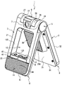
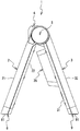
- FIG. 2 is a diagram showing a state in which a camera device 1 is connected to a video conference terminal 10 with a cable 4. It is a perspective view of the camera apparatus 1 of an open state. It is a perspective view of camera device 1 in a closed state. It is a front view of the camera apparatus 1 in a closed state. It is a right view of the camera apparatus 1 in a closed state. It is a right view of the camera apparatus 1 of an open state.
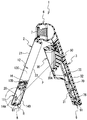
- FIG. 5 is a cross-sectional view taken along the line II in FIG. It is sectional drawing of the open state of the camera apparatus 1 corresponding to the cross-sectional position of FIG.
- FIG. 3 is a view showing a lower part of the back surface 22 of the first housing 2.
- the upper side, the lower side, the lower right side, and the upper left side are defined as the upper side, the lower side, the right side, and the left side of the camera device 1, respectively.
- the camera device 1 is used by being connected to a video conference terminal 10 via a cable 4.
- the camera device 1 images the user at the local site and inputs the video information to the video conference terminal 10.
- the camera device 1 has both a microphone function for inputting the user's voice to the video conference terminal and a speaker function for outputting the voice of the user at another site.
- the camera device 1 includes a first casing 2 and a second casing 3.
- the first housing 2 and the second housing 3 are connected to each other via a rotating shaft 5 at the upper portion thereof, and can be folded by rotating around the rotating shaft 5.
- a camera device 6 that is pivotally supported by a rotating shaft 5 is provided at the upper center of the camera device 1.
- a lens unit 7 is provided at the front center of the camera device 6.
- a microphone unit 11 for capturing a user's voice is provided at a lower portion of the front surface 21 of the first housing 2.
- a speaker unit 35 that protrudes slightly downward toward the front side and outputs sound is provided.
- the camera device 1 is placed on a desk that is a horizontal plane with the axial direction of the rotary shaft 5 parallel to the horizontal plane and the first casing 2 and the second casing 3 opened at a maximum angle. Can be independent.
- the camera device 6 is rotated and the lens unit 7 is directed to the user, whereby the installation of the camera device 1 is completed.
- the camera device 1 captures the voice of the user at the local site with the microphone unit 11.
- the sound of another base is output from the speaker unit 35.
- the state where the camera device 1 is opened at the maximum angle and installed on the desk as shown in FIGS. 2 and 6 will be referred to as the “open state”, and the folded state shown in FIGS. “Closed”.
- the first housing 2 is formed in a substantially rectangular thin plate shape that is vertically long when viewed from the front.
- An opening 12 having a substantially rectangular shape when viewed from the front is provided in the approximate center of the first housing 2.
- the opening 12 is positioned facing the speaker unit 35 located rearward in the open state. Therefore, the first housing 2 does not hinder the sound output from the speaker unit 35.
- the opening portion 12 has a function of storing the speaker portion 35 protruding from the front surface 31 of the second housing 3 inside in the closed state.
- a recess 19 cut out in a substantially rectangular shape is provided at the center in the left-right direction at the top of the first housing 2.
- a camera device 6 that is pivotally supported about the rotation shaft 5 is provided inside the recess 19.
- the camera device 6 is rotated to expose the lens unit 7 to the outside.
- the camera device 6 is rotated to house the lens unit 7 inside the recess 19. Since the lens unit 7 can be stored, the lens unit 7 can be prevented from being damaged when not in use.
- the microphone unit 11 is provided at the lower part of the front surface 21 of the first housing 2.
- the microphone portion 11 is provided with a plurality of through holes 14 ⁇ / b> A in a mesh shape for capturing the sound in front of the camera device 1.
- a microphone 20 is provided inside the first housing 2 located in the microphone unit 11.
- the microphone 20 is a “unidirectional microphone” having directivity in front of the first housing 2.
- a plurality of through-holes 14 ⁇ / b> B for picking up sound behind the camera device 1 are provided in a mesh shape in the lower portion of the back surface 22 of the first housing 2 facing the back surface side of the microphone 20. ing.
- the opening 12 forms an upper inner surface 12A, a right inner surface 12B, a left inner surface 12C, and a lower inner surface 12D when the camera device 1 is in the open position.
- the lower inner surface 12D is inclined obliquely upward toward the rear.
- lower side inner surface 12D is substantially horizontal.
- an operation unit 55 having four buttons for operating the camera device 1 is provided on the lower inner surface 12D.
- the operation unit 55 is provided with a power button 15, a microphone mute button 16, a volume plus button 17 for raising the speaker volume, and a volume minus button 18 for lowering the speaker volume in order from the left side to the right side. .
- the lower inner surface 12D becomes substantially horizontal, so that the user can easily operate the operation unit 55 and the usability is improved.
- the first casing 2 and the second casing are formed on the left and right sides of the concave portion 19 of the first casing 2 in a semicircular arc shape from the upper part of the front surface 21 toward the rear.
- the to-be-latched parts 27 and 28 for latching the latching parts 37 and 38 provided at the upper end part of the second housing 3 are respectively provided.
- Each terminal part toward the rear of the locked parts 27 and 28 is located at the uppermost part of the front surface 21 and is cut in a direction orthogonal to the rotation shaft 5.
- grounding portions 8 and 9 for grounding on the desk are provided at the lower ends of the first housing 2 and the second housing 3.
- the grounding portion 8 is inclined obliquely upward at a predetermined angle from the front surface 21 side toward the rear surface 22 side.
- the grounding portion 9 is inclined obliquely upward at a predetermined angle from the back surface 32 side to the front surface 31 side.
- the inclined surfaces of the grounding portions 8 and 9 are formed so as to be horizontal when the camera device 1 is opened at the maximum angle as shown in FIGS.
- Non-slip stoppers 81 and 91 are fixed to the grounding portions 8 and 9. Since both of the grounding portions 8 and 9 can be grounded with respect to the desk on a horizontal plane, the camera device 1 can stably hold the posture in the opened state.
- the second housing 3 is formed in a substantially rectangular thin plate shape that is vertically long when viewed from the front.
- casing 3 is connected with the rotating shaft 5 at the upper end part so that rotation is possible.
- a recess (not shown) cut out in a substantially rectangular shape for storing the camera device 6 is also provided at the center in the left-right direction at the top of the second housing 3.
- a prism-shaped speaker portion 35 that protrudes forward in the direction orthogonal to the front surface 31 is provided at the approximate center of the front surface 31 of the second housing 3.
- a plurality of through holes 35 ⁇ / b> A are provided in a mesh shape on the front surface of the speaker unit 35.
- a control board 70 for controlling the operation of the camera device 1 is fixed inside the second housing 3 with a plurality of screws 75.
- a speaker 50 is provided inside the speaker unit 35.
- the speaker 50 is supported so that the audio output direction is directed in front of the camera device 1 and substantially horizontally when the camera device 1 is installed on a desk in an open state.
- the sound output from the speaker 50 is output from the through hole 35 ⁇ / b> A of the speaker unit 35 to the front of the camera device 1 and substantially horizontally.
- the left and right sides of the cutout portion of the second housing 3 are formed in a semicircular arc shape from the upper part of the rear surface 32 toward the front, and the first housing 2 and the second housing 3 are formed.
- locking portions 37 and 38 for locking to the locked portions 27 and 28 provided at the upper end portion of the first housing 2 are provided.
- Each terminal portion toward the front of the locking portions 37 and 38 is cut in a direction orthogonal to the rotation shaft 5.
- the opening degree of the first housing 2 and the second housing 3 is the maximum angle.
- casing 3 shall make a maximum angle into 90 degrees or less, when the installation area on the desk of the camera apparatus 1 is considered.
- casing 3 is not restricted to this, Another structure may be sufficient.
- the microphone 20 is a unidirectional microphone that easily captures a specific direction. As shown in FIG. 8, the case where the opened camera device 1 is installed on a desk will be described as an example.
- the sound behind the camera device 1 reaches the back side of the diaphragm of the microphone 20 as direct sound from the through hole 14B provided on the lower side of the back surface 22 of the first housing 2.
- the same sound also reaches the front side of the first housing 2 and reaches the front side of the diaphragm as an indirect sound with a slight delay from the through hole 14A provided in the microphone portion 11 of the front surface 21 of the first housing 2.
- An obstacle or the like (not shown) is provided between the through hole 14B and the back side of the diaphragm. Therefore, the speed of the direct sound is delayed and arrives simultaneously with the indirect sound. Since this sound is canceled out as the same amount of energy generated simultaneously on the front and back of the diaphragm, there is no electrical output.
- the sound in front of the camera device 1 is first transmitted to the front side of the diaphragm of the microphone 20 from the through hole 14A provided in the microphone portion 11 of the front surface 21 of the first housing 2. Subsequent wraparound to the back side of the first housing 2 is further delayed by the above-mentioned obstacle. Due to this time difference, energy is not canceled out, but is output electrically.
- the microphone 20 has a directivity R as shown by a one-dot chain line in FIG.
- the camera device 1 As shown in FIG. 8, in the camera device 1, the camera device 6, the speaker 50, and the microphone 20 are positioned in this order from top to bottom.
- the camera device 6 is located at the top of the camera device 1. Thereby, as shown in FIGS. 2 and 6, when the camera device 1 is installed on a desk, the height position of the lens unit 7 is not too low. Therefore, the user can be photographed at an appropriate height.
- the microphone 20 is located at the bottom of the camera device 1.
- the microphone 20 is closest to the desk. Therefore, since the time lag until the voice directly reaching the user's microphone 20 and the reflected voice reaches the microphone 20 is small, the user's voice can be acquired well.
- the speaker 50 is located above the microphone 20. Therefore, since most of the sound output from the speaker 50 is not reflected on the desk, the user can hear the sound output from the speaker 50 well and clearly.
- the microphone 20 and the speaker 50 are separated from each other by a predetermined distance along the output direction of the speaker 50.
- the microphone 20 and the speaker 50 are separated from each other by a predetermined distance along the output direction of the speaker 50, the echo phenomenon that occurs when the sound output from the speaker 50 is picked up by the microphone 20 can be reduced.
- the positional relationship between the microphone 20 and the speaker 50 is determined by the directivity of the microphone 20 and the output direction of the speaker 50.
- the directivity R of the microphone 20 is a cardioid shape that maximizes the front of the camera device 1, and the sensitivity decreases toward the center of the back surface while turning around the back side of the microphone 20.
- the speaker 50 is positioned slightly above and behind the microphone 20 having such directivity R, and the microphone 20 and the speaker 50 are separated from each other by a predetermined distance along the output direction of the speaker 50.
- the front center of the speaker 50 and the center of the microphone 20 are connected by a virtual straight line P indicated by a dotted line.
- the virtual straight line P is positioned so as to intersect with a portion where the sensitivity is reduced due to the directivity of the microphone 20. Thereby, the input signal of the microphone 20 can be effectively lowered with respect to the audio output signal of the speaker 50.
- the microphone 20 and the speaker 50 are positioned in the above-described positional relationship, so that the echo phenomenon caused by the microphone 20 picking up the sound output from the speaker 50. Can be reduced. Therefore, since the voice output from the speaker 50 can be heard clearly, the progress of the video conference can be improved.
- the grounding portion 8 of the first housing 2 is inclined obliquely upward from the front to the rear.
- the grounding portion 9 of the second housing 3 is inclined obliquely upward from the rear to the front.
- the grounding portion 8 of the first housing 2 and the grounding portion 9 of the second housing 3 have the same positional relationship. Therefore, the grounding portions 8 and 9 form a V shape.
- the grounding portions 8 and 9 are inclined surfaces having a symmetrical shape centering on an opposing surface where the first housing 2 and the second housing 3 face each other. This is due to the structure in which the first housing 2 and the second housing 3 open around the rotation shaft 5 and the grounding portions 8 and 9 in the opened state are horizontal. Because of these characteristics, it is easy to apply fingers of both hands to the grounding portions 8 and 9, and it is easy to hook the fingers, so that the operability when opening the camera device 1 is improved.
- the speaker portion 35 protruding from the front surface 31 of the second housing 3 is located inside the opening 12 of the first housing 2.
- the camera device 1 in the closed state becomes a compact, substantially rectangular parallelepiped terminal device, it can be easily carried and portability is improved. Further, as shown in FIG. 5, the camera device 1 in the closed state does not have a portion that protrudes outward, so that it is not caught on clothing or the like.
- the camera device 1 includes the first housing 2 and the second housing 3 and is configured to be foldable by rotating around the rotation shaft 5.
- the first casing 2 is provided with a microphone 20, and the second casing 3 is provided with a speaker 50.
- the camera device 1 can be placed on a desk and made to stand on its own with the rotary shaft 5 facing upward and the first housing 2 and the second housing 3 opened at the maximum angle.
- the microphone 20 has a single directivity in the same direction as the output direction of the speaker 50.
- the microphone 20 and the speaker 50 are positioned with a predetermined distance therebetween. Thereby, the echo phenomenon by the microphone 20 picking up the sound output from the speaker 50 can be reduced. Therefore, since the voice output from the speaker 50 can be heard clearly, the progress of the video conference can be improved.
- this invention is not limited to the said embodiment, A various deformation
- the cable 4 to which the video conference terminal 10 is connected is connected to the input / output unit provided in the first housing 2, and audio information or video information is input / output through the cable 4.
- audio information and video information may be input / output by wireless communication with a video conference terminal.
- an antenna for communicating with the video conference terminal may be stored inside the first casing 2 or the second casing 3.
- the directing direction of the microphone 20 is substantially horizontal, but may be slightly downward.
- the sound of the speaker 50 is input to the back surface of the microphone 20 having as low a sensitivity as possible in the directivity R. Therefore, the echo phenomenon can be more reliably reduced.
- the front direction of the speaker 50 is substantially horizontal, but may be slightly upward.
Landscapes
- Engineering & Computer Science (AREA)
- Signal Processing (AREA)
- Human Computer Interaction (AREA)
- Health & Medical Sciences (AREA)
- General Health & Medical Sciences (AREA)
- Otolaryngology (AREA)
- Physics & Mathematics (AREA)
- Acoustics & Sound (AREA)
- Studio Devices (AREA)
- Details Of Audible-Bandwidth Transducers (AREA)
- Telephone Set Structure (AREA)
Abstract
水平面に設置した状態でエコー現象を低減できる端末機器を提供する。カメラ機器1は、第一筐体2と第二筐体3とを備え、回転軸を中心に折り畳み可能に構成されている。第一筐体2にはマイク20が設けられ、第二筐体3にはスピーカ50が設けられている。カメラ機器1は、第一筐体2と第二筐体3とを最大角度で開いた状態で、机上に載置して自立させることができる。マイク20は、スピーカ50の出力方向と同方向に単一指向性を有する。カメラ機器1を開状態で机上に設置した場合、マイク20とスピーカ50との間が所定距離離間して位置決めされる。これにより、スピーカ50から出力された音声をマイク20が拾うことによるエコー現象を低減できる。
Description
本発明は、カメラ、スピーカ及びマイクを備えた端末機器に関する。
従来より、同時に通話撮影機能を有し、広角撮影及び直立機能を備えたネットワーク電話が知られている(例えば、特許文献1参照)。この電話の本体正面の上部にはカメラ(カメラ底台)が軸支され、正面中央にはスピーカが設けられ、その下方にはマイクが設けられている。利用者は、本体の下部に回転可能に支持された底台を展開することによって、水平面に本体を直立して設置できる。
特許文献1に記載のネットワーク電話の構造を、テレビ会議用のカメラ機器に適用した場合等において、水平面に直立して設置した状態では、本体の前後方向において、スピーカとマイクとがほぼ同一位置となる。したがって、スピーカから出力される音声がマイクに拾われてしまうため、エコー現象(反響)を生じてしまう。
本発明は、上記課題を解決するためになされたものであり、水平面に設置した状態でエコー現象を低減できる端末機器を提供することを目的とする。
本発明に係る端末機器は、カメラ、スピーカ及びマイクを備え、前記スピーカの出力方向と同方向に前記マイクの指向性を有する端末機器であって、前記端末機器を水平面に設置するときに、前記スピーカの出力方向において、かつ前記カメラよりも下方の位置で、前記マイクと前記スピーカとが互いに近づいた閉状態から、前記マイクと前記スピーカとの間が所定距離離間する開状態となるように、前記マイク又は前記スピーカを可動させる可動機構を備えたことを特徴とする。
端末機器は、水平面に設置する際に、可動機構によって開状態にする。開状態では、マイクとスピーカとの間が所定距離離間する。これにより、スピーカから出力された音声がマイクに入力され難くなるので、設置時においてエコー現象を低減できる。また、カメラよりも下方にマイクとスピーカがあるので、カメラは端末機器における上側に位置する。故に、端末機器を机上に置いたときに、カメラの高さ位置が低すぎないので、利用者を良好に撮影できる。
前記可動機構は、前記スピーカの前記出力方向における前記スピーカの前方において、かつ前記カメラよりも下方の位置で、前記閉状態から前記開状態となるように、前記マイク又は前記スピーカを可動させてもよい。マイクはスピーカよりも前方に位置するので、マイクの音声入力においてスピーカが障壁とならない。故に、マイクで利用者の音声を良好に取得できる。
前記端末機器を水平面に設置した状態において、前記端末機器を正面からみたときに、前記カメラの下方に前記スピーカが配置され、前記スピーカの下方に前記マイクが配置されていてもよい。カメラよりも下方にマイクとスピーカがあるので、カメラは端末機器における上側に位置する。故に、端末機器を机上に置いたときに、カメラの高さ位置が低すぎないので、利用者を良好に撮影できる。また、スピーカは、マイクの上側に位置するので、机上に設置した場合に、スピーカから出力された音声が机上に反射しない。これにより、利用者は、スピーカから出力された音声を良好に聞くことができる。他方、マイクは机上に近いので、利用者から直接伝わる音声のみならず、机上に反射した音声も重ねて捉えることができる。これにより、端末機器を設置した拠点の利用者の音声を良好に捉えることができる。
マイクは、単一指向性マイクであるので、特定方向の音声を良好に取得できる。第1態様では、特定方向をスピーカの出力方向と同方向にしている。これにより、マイクは、スピーカの出力方向と同方向の音声を選択的に、かつ良好に捉えることができる。
前記端末機器を水平面に設置した状態において、前記スピーカの正面方向と、前記マイクの指向方向とがともに水平であるようにしてもよい。これにより、スピーカから出力された音声が机上に反射することなく、利用者に直接伝えることができるので、利用者は、スピーカから出力された音声を明確に聞き取ることができる。さらに、マイクの指向方向も水平であるので、利用者の音声を確実に捉えることができる。
前記可動機構は、前記マイクを保持する第一筐体と、当該第一筐体に対して回転軸を介して折り畳み可能に連結され、かつ前記スピーカを保持する第二筐体とを備え、前記カメラは、前記回転軸を中心に回転可能に支持され、前記閉状態は、前記第一筐体と前記第二筐体とを折り畳んだ状態であって、前記開状態は、前記第一筐体と前記第二筐体とを所定角度で開いた状態であって、前記端末機器を前記開状態で、かつ前記回転軸の軸心方向を水平面に対して平行にした状態で水平面に設置したときに、前記マイクは、前記スピーカの正面方向において、前記スピーカから前記所定距離離間した位置に保持されていてもよい。このような構造により、開状態では、マイクとスピーカとの間を確実に所定距離離間させることができる。これにより、スピーカから出力された音声がマイクに安定的に減衰した状態で入力されるので、設置時においてエコー現象を低減できる。
前記マイクは前記第一筐体の下部に設けられ、前記第一筐体の前記第二筐体に対向する背面には、前記スピーカが出力する音を前記マイクに対して後方から直接伝えるための貫通孔を設けてもよい。マイクは第一筐体の下部に設けられているので、マイクを机上に近付けることができる。故に、利用者のマイクに直接届く音声と、反射した音声がマイクに届くまでのタイムラグが少ないので、利用者の音声を良好に取得できる。
スピーカから出力された音は、第一筐体の背面に設けた貫通孔から入ってマイクの振動板の裏側に直接音として届く。同じ音は回り込み、少し遅れて振動板の表側にも間接音として届く。そして直接音の速度を遅らせて間接音と同時に到達するようにすると、この音は振動板の表と裏で同時に生じた同量のエネルギーとして相殺され、電気出力にならない。故に、マイクの後方の音声を拾わないようにすることができる。
前記第一筐体において、前記第二筐体に設けられた前記スピーカに相対する部分に開口部を設け、前記閉状態では、前記開口部の内側に前記スピーカが格納されるようにしてもよい。閉状態では、開口部の内側にスピーカが格納されるので、スピーカが外方に突出せず、コンパクトな状態で端末機器を持ち運ぶことができる。一方、開状態では、スピーカに相対する位置に第一筐体の開口部が位置する。故に、第一筐体はスピーカの出力した音声の妨げにならず、スピーカの出力した音声を利用者に良好に伝えることができる。
前記端末機器を前記開状態で水平面に設置したときの前記開口部の下側の内周面には、前記端末機器を操作するための操作部を設けてもよい。操作部が操作し易い位置にあるので、使い勝手のよい端末機器を提供できる。
前記マイクと、前記スピーカの正面中心とを仮想的に結んだ直線は、前記マイクの指向性により感度が低下する部分と交わるようにしてもよい。これにより、スピーカから出力した音声に対してマイクの感度が低くなるので、エコー現象を低減できる。
以下、本発明の端末機器の一実施形態であるカメラ機器1について、図面を参照して説明する。なお、図2,図3の上側、下側、右斜め下側、左斜め上側を、カメラ機器1の上側、下側、右側、左側とする。
図1に示すように、カメラ機器1は、テレビ会議端末10にケーブル4を介して接続して使用される。カメラ機器1は、自拠点の利用者を撮像し、その映像情報をテレビ会議端末10に入力する。カメラ機器1は、カメラ機能の他、利用者の音声をテレビ会議端末に入力するマイク機能、及び他拠点の利用者の音声を出力するスピーカ機能を併せ持つ。
図2,図3に示すように、カメラ機器1は、第一筐体2と、第二筐体3とを備えている。第一筐体2と第二筐体3とは、その上部で回転軸5を介して連結され、回転軸5を中心に回動することで折り畳み可能となっている。カメラ機器1の上部中央には、回転軸5に回動可能に軸支されたカメラ装置6が設けられている。カメラ装置6の正面中心にはレンズ部7が設けられている。第一筐体2の前面21の下部には、利用者の音声を捉えるためのマイク部11が設けられている。第二筐体3の前面31の略中央には、前側に向かってやや斜め下方に突出し、音声が出力されるスピーカ部35が設けられている。
カメラ機器1は、回転軸5の軸心方向を水平面に対して平行にし、かつ第一筐体2と第二筐体3とを最大角度で開いた状態で、水平面である机上に載置して自立させることができる。カメラ機器1が自立した状態で、カメラ装置6を回動させ、レンズ部7を利用者に向けることで、カメラ機器1の設置が完了する。カメラ機器1は、自拠点の利用者の音声をマイク部11で捉える。他拠点の音声は、スピーカ部35から出力される。なお、以下説明において、図2、図6等に示した、カメラ機器1を最大角度で開いて机上に設置する状態を「開状態」とし、図3~図5等に示した折り畳んだ状態を「閉状態」とする。
図2~図4に示すように、第一筐体2は、正面視縦長の略長方形の薄板状に形成されている。第一筐体2の略中央には、正面視略長方形状の開口部12が設けられている。図2に示すように、開口部12は、開状態で、後方に位置するスピーカ部35に対向して位置する。故に、第一筐体2が、スピーカ部35から出力される音声の妨げにはならない。一方、図3に示すように、開口部12は、閉状態で、第二筐体3の前面31に突設されたスピーカ部35を内側に格納する機能を有する。
第一筐体2の上部の左右方向中央には、略長方形状に切り欠いた凹部19が設けられている。凹部19の内側には、回転軸5を中心に回動可能に軸支されたカメラ装置6が設けられている。カメラ装置6を使用する時は、図2に示すように、カメラ装置6を回動させてレンズ部7を外部に露出させる。カメラ装置6を使用しない時は、図3に示すように、カメラ装置6を回動させてレンズ部7を凹部19の内側に収納する。レンズ部7を収納できるので、使用しない時にレンズ部7が損傷するのを防止できる。
第一筐体2の前面21の下部には、マイク部11が設けられている。マイク部11には、カメラ機器1の前方の音声を捉えるための複数の貫通孔14Aが網目状に設けられている。図7,図8に示すように、マイク部11に位置する第一筐体2の内側には、マイク20が設けられている。マイク20は、第一筐体2の前方に指向性を有する「単一指向性マイク」である。図9に示すように、マイク20の背面側に対向する第一筐体2の背面22の下部には、カメラ機器1の後方の音声を拾うための複数の貫通孔14Bが網目状に設けられている。
図2,図4に示すように、開口部12は、カメラ機器1の開状態の姿勢において、上側内面12A、右側内面12B、左側内面12C、及び下側内面12Dを形成している。図4に示すように、カメラ機器1を、第一筐体2の前面21を鉛直方向に立たせた状態において、下側内面12Dは後方に向かって斜め上方に傾斜している。そして、カメラ機器1を開状態にして机上に設置した状態では、図2に示すように、下側内面12Dは略水平となっている。
下側内面12Dには、カメラ機器1を操作するための4つのボタンを有する操作部55が設けられている。操作部55には、左側から右側に向かって順に、電源ボタン15、マイクミュートボタン16、スピーカ音量を上げるための音量プラスボタン17、スピーカ音量を下げるための音量マイナスボタン18が各々設けられている。カメラ機器1が開状態で机上に設置されたときに下側内面12Dが略水平となるので、利用者にとって操作部55の操作がし易くなり、使い勝手が向上する。
図2,図3に示すように、第一筐体2の凹部19の左右両側には、前面21の上部から後方に向かって半円弧状に形成され、第一筐体2と第二筐体3を開く際に、第二筐体3の上端部に設けられた係止部37,38が係止するための被係止部27,28が各々設けられている。被係止部27,28の後方に向かう各終端部は、前面21の最上部に位置し、かつ回転軸5に対して直交する方向に切断されている。
図3,図5に示すように、第一筐体2、第二筐体3の下端部には、机上に接地するための接地部8,9が設けられている。接地部8は、前面21側から背面22側に向かって所定角度で斜め上方に傾斜している。接地部9は、背面32側から前面31側に向かって所定角度で斜め上方に傾斜している。接地部8,9の傾斜面は、図6、図8に示すようカメラ機器1を最大角度で開き、机上に自立させたときに水平となるように形成されている。接地部8,9には滑り止めのストッパ81,91が固定されている。接地部8,9は、机上に対して何れも水平面で接地できるので、カメラ機器1は、開いた状態の姿勢を安定して保持できる。
図2に示すように、第二筐体3は、正面視縦長の略長方形の薄板状に形成されている。第二筐体3は、その上端部において回転軸5に回動可能に連結されている。第二筐体3の上部の左右方向中央にも、カメラ装置6を格納するための略長方形状に切り欠いた図示しない凹部が設けられている。第二筐体3の前面31の略中央には、前面31に直交する方向の前方に向かって突出する角柱状のスピーカ部35が設けられている。スピーカ部35の前面には、複数の貫通孔35Aが網目状に設けられている。
図8に示すように、第二筐体3の内側には、カメラ機器1の動作を制御するための制御基板70が複数の螺子75で固定されている。スピーカ部35の内側には、スピーカ50が設けられている。スピーカ50は、カメラ機器1を開状態で机上に設置した場合に、音声の出力方向を、カメラ機器1の前方にかつ略水平に向けられるように支持されている。スピーカ50から出力された音声は、スピーカ部35の貫通孔35Aからカメラ機器1の前方にかつ略水平に向かって出力される。これにより、スピーカ50から出力された音声を利用者に対して直接伝えることができるので、利用者は、スピーカ50から出力された音声を明瞭に聞き取ることができる。
図2,図3に示すように、第二筐体3の切り欠き部の左右両側には、背面32の上部から前方に向かって半円弧状に形成され、第一筐体2と第二筐体3を開く際に、第一筐体2の上端部に設けられた被係止部27,28に係止するための係止部37,38が各々設けられている。係止部37,38の前方に向かう各終端部は、回転軸5に対して直交する方向に切断されている。
図2に示すように、第一筐体2と第二筐体3とを開いたときに、係止部37,38が被係止部27,28に係止することによって、第一筐体2と第二筐体3の回動が制限される。このとき、第一筐体2と第二筐体3との開度は最大角度となる。なお、第一筐体2と第二筐体3との開度は、カメラ機器1の机上における設置面積を考慮すると、最大角度を90°以下にするのが好ましい。なお、第一筐体2と第二筐体3の回動を制限する構造は、これに限らず、他の構造でもよい。
マイク20は、特定の方向を捉えやすい性質を持つ単一指向性のマイクである。図8に示すように、開状態のカメラ機器1を机上に設置した場合を例に説明する。カメラ機器1の後方の音声は、第一筐体2の背面22の下側に設けられた貫通孔14Bからマイク20の振動板の裏側に直接音として届く。同じ音声は第一筐体2の前側にも回り込み、第一筐体2の前面21のマイク部11に設けられた貫通孔14Aから少し遅れて振動板の表側にも間接音として届く。貫通孔14Bから振動板の裏側までの間には図示しない障害物等が設けられている。それ故、直接音の速度が遅れて間接音と同時に到達する。この音声は振動板の表と裏で同時に生じた同量のエネルギーとして相殺されるので、電気出力にならない。
一方、カメラ機器1の前方の音声は、第一筐体2の前面21のマイク部11に設けられた貫通孔14Aから、まず先にマイク20の振動板の表側に伝わる。その後の第一筐体2の裏側への回り込みは、上述の障害物によって到達がさらに遅くなる。この時間差によってエネルギーは相殺されずに電気出力される。このような原理で、マイク20はカメラ機器1の前方に対し、図8の一点鎖線で示すような指向性Rを有する。
図8に示すように、カメラ機器1において、上から下に向かって、カメラ装置6、スピーカ50、マイク20の順に位置する。カメラ装置6は、カメラ機器1の最上部に位置している。これにより、図2,図6に示すように、カメラ機器1を机上に設置したときに、レンズ部7の高さ位置が低すぎない。故に、適切な高さで利用者を撮影できる。
これに対し、マイク20は、カメラ機器1の最下部に位置している。マイク20は机上に最も近い。故に、利用者のマイク20に直接届く音声と、反射した音声がマイク20に届くまでのタイムラグが少ないので、利用者の音声を良好に取得できる。
スピーカ50は、マイク20の上側に位置している。従って、スピーカ50から出力された音声の大部分は机上に反射しないので、利用者は、スピーカ50から出力された音声を良好にかつ明瞭に聞き取ることができる。
図8に示すように、カメラ機器1が開状態において、マイク20とスピーカ50との間はスピーカ50の出力方向に沿って所定距離離れるようになっている。マイク20とスピーカ50とがスピーカ50の出力方向に沿って所定距離離れることによって、スピーカ50から出力された音声がマイク20に拾われることによって生じるエコー現象を低減できる。これらマイク20とスピーカ50との位置関係は、マイク20の指向性とスピーカ50の出力方向によって決まる。
マイク20の指向性Rは、カメラ機器1の前方を最大とするカーディオイド型状であり、マイク20の裏側に回り込みつつ裏面の中心部に向かって感度が低下している。このような指向性Rを有するマイク20の後方のやや上方にスピーカ50が位置し、マイク20とスピーカ50との間がスピーカ50の出力方向に沿って所定距離離れている。
このような位置関係において、スピーカ50の正面中心と、マイク20の中心とを点線で示した仮想直線Pで結ぶ。仮想直線Pは、マイク20の指向性により感度が低下する部分と交わるように位置している。これにより、マイク20の入力信号を、スピーカ50の音声出力信号に対して効果的に低くすることができる。
このように、カメラ機器1を開状態にしたときに、マイク20とスピーカ50とが、上記の位置関係に位置決めされることで、スピーカ50から出力された音声をマイク20が拾うことによるエコー現象を低減できる。よって、スピーカ50から出力された音声を明瞭に聞き取ることができるので、テレビ会議の進行を良好にできる。
図5に示すように、折り畳まれたカメラ機器1を回転軸5の軸方向から見た場合、第一筐体2の接地部8は、前方から後方に向かって斜め上方に傾斜している。これに対し、第二筐体3の接地部9は、後方から前方に向かって斜め上方に傾斜している。さらに、カメラ機器1を折り畳んだ状態では、第一筐体2の接地部8と、第二筐体3の接地部9とは、同じ位置関係となっている。故に、接地部8,9はV字形状を形成している。
接地部8,9は、第一筐体2と第二筐体3とが対向する対向面を中心とした対称形状の傾斜面となっている。これは、第一筐体2と第二筐体3とが回転軸5を中心に開く構造であって、その開いた状態の接地部8,9を水平にしたことに起因する。これらの特徴から、接地部8,9に対して両手の指を当てやすく、さらには指を引っ掛けやすくなるので、カメラ機器1を開く際の操作性が向上する。
図2~図5に示すように、カメラ機器1を折り畳んで閉状態にした場合、第二筐体3の前面31から突出するスピーカ部35が、第一筐体2の開口部12の内側に格納される。閉状態のカメラ機器1は、コンパクトな略直方体の端末機器となるので、手軽に持ち運ぶことができ、携帯性が向上する。また、図5に示すように、閉状態のカメラ機器1には外方に突出する部分もないので、服飾等に引っ掛けることもない。
以上説明したように、本実施形態であるカメラ機器1は、第一筐体2と第二筐体3とを備え、回転軸5を中心に回動することで折り畳み可能に構成されている。第一筐体2には、マイク20が設けられ、第二筐体3にはスピーカ50が設けられている。カメラ機器1は、回転軸5を上方に向け、第一筐体2と第二筐体3とを最大角度で開いた状態で、机上に載置して自立させることができる。マイク20は、スピーカ50の出力方向と同方向に単一指向性を有する。そして、カメラ機器1を開状態で机上に設置した場合、マイク20とスピーカ50との間が所定距離離間して位置決めされる。これにより、スピーカ50から出力された音声をマイク20が拾うことによるエコー現象を低減できる。よって、スピーカ50から出力された音声を明瞭に聞き取ることができるので、テレビ会議の進行を良好にできる。
なお、本発明は上記実施形態に限定されず、様々な変形が可能である。例えば、上記実施形態では、テレビ会議端末10が接続されたケーブル4を、第一筐体2に設けられた入出力部に接続し、ケーブル4を通じて音声情報または映像情報の入出力を行っている。
これに対し、例えば、テレビ会議端末と無線通信によって音声情報、映像情報の入出力を行うようにしてもよい。この場合、テレビ会議端末と通信するためのアンテナを、第一筐体2又は第二筐体3の内側に格納すればよい。
これに対し、例えば、テレビ会議端末と無線通信によって音声情報、映像情報の入出力を行うようにしてもよい。この場合、テレビ会議端末と通信するためのアンテナを、第一筐体2又は第二筐体3の内側に格納すればよい。
また、上記実施形態では、カメラ機器を開状態で机上に設置したときに、マイク20の指向方向は略水平にしているが、やや下向きにしてもよい。この場合、指向性Rの内、出来るだけ感度の低いマイク20の背面に対してスピーカ50の音声が入力される。故に、エコー現象をさらに確実に低減できる。さらに、上記実施形態では、スピーカ50の正面方向を略水平にしているが、やや上向きにしてもよい。
1 カメラ機器
2 第一筐体
3 第二筐体
5 回転軸
6 カメラ装置
12 開口部
12D 下側内面
14B 貫通孔
20 マイク
50 スピーカ
2 第一筐体
3 第二筐体
5 回転軸
6 カメラ装置
12 開口部
12D 下側内面
14B 貫通孔
20 マイク
50 スピーカ
Claims (10)
- カメラ、スピーカ及びマイクを備え、前記スピーカの出力方向と同方向に前記マイクの指向性を有する端末機器であって、
前記端末機器を水平面に設置するときに、前記スピーカの出力方向において、かつ前記カメラよりも下方の位置で、前記マイクと前記スピーカとが互いに近づいた閉状態から、前記マイクと前記スピーカとの間が所定距離離間する開状態となるように、前記マイク又は前記スピーカを可動させる可動機構を備えたことを特徴とする端末機器。 - 前記可動機構は、前記スピーカの前記出力方向における前記スピーカの前方において、かつ前記カメラよりも下方の位置で、前記閉状態から前記開状態となるように、前記マイク又は前記スピーカを可動させることを特徴とする請求項1に記載の端末機器。
- 前記端末機器を水平面に設置した状態において、
前記端末機器を正面からみたときに、
前記カメラの下方に前記スピーカが配置され、前記スピーカの下方に前記マイクが配置されていることを特徴とする請求項1に記載の端末機器。 - 前記マイクは、単一指向性マイクであることを特徴とする請求項1に記載の端末機器。
- 前記端末機器を水平面に設置した状態において、
前記スピーカの正面方向と、前記マイクの指向方向とがともに水平であることを特徴とする請求項4に記載の端末機器。 - 前記可動機構は、
前記マイクを保持する第一筐体と、
当該第一筐体に対して回転軸を介して折り畳み可能に連結され、かつ前記スピーカを保持する第二筐体と
を備え、
前記カメラは、前記回転軸を中心に回転可能に支持され、
前記閉状態は、前記第一筐体と前記第二筐体とを折り畳んだ状態であって、
前記開状態は、前記第一筐体と前記第二筐体とを所定角度で開いた状態であって、
前記端末機器を前記開状態で、かつ前記回転軸の軸心方向を水平面に対して平行にした状態で水平面に設置したときに、前記マイクは、前記スピーカの正面方向において、前記スピーカから前記所定距離離間した位置に保持されることを特徴とする請求項1に記載の端末機器。 - 前記マイクは前記第一筐体の下部に設けられ、
前記第一筐体の前記第二筐体に対向する背面には、前記スピーカが出力する音を前記マイクに対して後方から直接伝えるための貫通孔を設けたことを特徴とする請求項6に記載の端末機器。 - 前記第一筐体において、前記第二筐体に設けられた前記スピーカに相対する部分に開口部を設け、
前記閉状態では、前記開口部の内側に前記スピーカが格納されることを特徴とする請求項6に記載の端末機器。 - 前記端末機器を前記開状態で水平面に設置したときの前記開口部の下側の内周面には、前記端末機器を操作するための操作部を設けたことを特徴とする請求項8に記載の端末機器。
- 前記マイクと、前記スピーカの正面中心とを仮想的に結んだ直線は、前記マイクの指向性により感度が低下する部分と交わることを特徴とする請求項1から9の何れかに記載の端末機器。
Applications Claiming Priority (2)
| Application Number | Priority Date | Filing Date | Title |
|---|---|---|---|
| JP2010266617A JP2012119851A (ja) | 2010-11-30 | 2010-11-30 | 端末機器 |
| JP2010-266617 | 2010-11-30 |
Publications (1)
| Publication Number | Publication Date |
|---|---|
| WO2012073784A1 true WO2012073784A1 (ja) | 2012-06-07 |
Family
ID=46171726
Family Applications (1)
| Application Number | Title | Priority Date | Filing Date |
|---|---|---|---|
| PCT/JP2011/077045 Ceased WO2012073784A1 (ja) | 2010-11-30 | 2011-11-24 | 端末機器 |
Country Status (2)
| Country | Link |
|---|---|
| JP (1) | JP2012119851A (ja) |
| WO (1) | WO2012073784A1 (ja) |
Citations (5)
| Publication number | Priority date | Publication date | Assignee | Title |
|---|---|---|---|---|
| JP2002295445A (ja) * | 2001-03-29 | 2002-10-09 | Denso Corp | 携帯電話機 |
| JP2003163824A (ja) * | 2001-11-28 | 2003-06-06 | Minolta Co Ltd | カメラ付き折畳式携帯機器 |
| JP2004320742A (ja) * | 2003-04-14 | 2004-11-11 | Samsung Electronics Co Ltd | 回転型カメラレンズハウジングを備える携帯用端末機 |
| JP2006067285A (ja) * | 2004-08-27 | 2006-03-09 | Kyocera Corp | 携帯電子機器 |
| JP2009100086A (ja) * | 2007-10-15 | 2009-05-07 | Casio Hitachi Mobile Communications Co Ltd | 端末装置 |
-
2010
- 2010-11-30 JP JP2010266617A patent/JP2012119851A/ja active Pending
-
2011
- 2011-11-24 WO PCT/JP2011/077045 patent/WO2012073784A1/ja not_active Ceased
Patent Citations (5)
| Publication number | Priority date | Publication date | Assignee | Title |
|---|---|---|---|---|
| JP2002295445A (ja) * | 2001-03-29 | 2002-10-09 | Denso Corp | 携帯電話機 |
| JP2003163824A (ja) * | 2001-11-28 | 2003-06-06 | Minolta Co Ltd | カメラ付き折畳式携帯機器 |
| JP2004320742A (ja) * | 2003-04-14 | 2004-11-11 | Samsung Electronics Co Ltd | 回転型カメラレンズハウジングを備える携帯用端末機 |
| JP2006067285A (ja) * | 2004-08-27 | 2006-03-09 | Kyocera Corp | 携帯電子機器 |
| JP2009100086A (ja) * | 2007-10-15 | 2009-05-07 | Casio Hitachi Mobile Communications Co Ltd | 端末装置 |
Also Published As
| Publication number | Publication date |
|---|---|
| JP2012119851A (ja) | 2012-06-21 |
Similar Documents
| Publication | Publication Date | Title |
|---|---|---|
| US10856075B2 (en) | Audio capture with multiple microphones | |
| US7436427B2 (en) | Integrated camera stand with wireless audio conversion and battery charging | |
| US20120052924A1 (en) | Headset with a Pivoting Microphone Arm and Speaker | |
| JP2009260948A (ja) | 音声処理装置 | |
| JP2009010593A (ja) | 携帯通信端末 | |
| CN209086689U (zh) | 一种拍摄角度可调的智能手表 | |
| JP4715208B2 (ja) | 携帯電話機 | |
| US20080205874A1 (en) | Wide coverage image capturing and standable web phone | |
| JP3610631B2 (ja) | 携帯用無線通信装置 | |
| WO2025113375A1 (zh) | 电子设备 | |
| JP4199576B2 (ja) | 折り畳み式携帯端末機 | |
| WO2007058622A1 (en) | Apparatus for audio reproduction and image capturing | |
| JP2014176042A (ja) | 通信装置、及び音声入出力ユニットの制御方法 | |
| JP2012119851A (ja) | 端末機器 | |
| JP5983993B2 (ja) | 会議装置 | |
| US7415294B1 (en) | Hands-free voice communication apparatus with integrated speakerphone and earpiece | |
| JP2014241524A (ja) | 通信装置、通信システム、プログラム及び通信装置の使用方法 | |
| JP2012119909A (ja) | 端末機器、エコー低減システム及び制御プログラム | |
| JP4201678B2 (ja) | 携帯型通信端末機 | |
| JP4384468B2 (ja) | 携帯型無線端末機 | |
| JP2014107785A (ja) | 携帯端末装置 | |
| JP4332403B2 (ja) | 携帯型電子機器 | |
| KR20010059498A (ko) | 영상 통신용 무선 단말기 | |
| CN110324445B (zh) | 电子装置及电子装置的控制方法 | |
| JP2004274594A (ja) | 携帯情報端末 |
Legal Events
| Date | Code | Title | Description |
|---|---|---|---|
| 121 | Ep: the epo has been informed by wipo that ep was designated in this application |
Ref document number: 11845504 Country of ref document: EP Kind code of ref document: A1 |
|
| NENP | Non-entry into the national phase |
Ref country code: DE |
|
| 122 | Ep: pct application non-entry in european phase |
Ref document number: 11845504 Country of ref document: EP Kind code of ref document: A1 |