WO2012073643A1 - 冷媒凝縮器 - Google Patents
冷媒凝縮器 Download PDFInfo
- Publication number
- WO2012073643A1 WO2012073643A1 PCT/JP2011/075376 JP2011075376W WO2012073643A1 WO 2012073643 A1 WO2012073643 A1 WO 2012073643A1 JP 2011075376 W JP2011075376 W JP 2011075376W WO 2012073643 A1 WO2012073643 A1 WO 2012073643A1
- Authority
- WO
- WIPO (PCT)
- Prior art keywords
- pipe
- core
- refrigerant
- liquid
- supercooling
- Prior art date
- Legal status (The legal status is an assumption and is not a legal conclusion. Google has not performed a legal analysis and makes no representation as to the accuracy of the status listed.)
- Ceased
Links
Images



Classifications
-
- F—MECHANICAL ENGINEERING; LIGHTING; HEATING; WEAPONS; BLASTING
- F25—REFRIGERATION OR COOLING; COMBINED HEATING AND REFRIGERATION SYSTEMS; HEAT PUMP SYSTEMS; MANUFACTURE OR STORAGE OF ICE; LIQUEFACTION SOLIDIFICATION OF GASES
- F25B—REFRIGERATION MACHINES, PLANTS OR SYSTEMS; COMBINED HEATING AND REFRIGERATION SYSTEMS; HEAT PUMP SYSTEMS
- F25B39/00—Evaporators; Condensers
- F25B39/04—Condensers
-
- F—MECHANICAL ENGINEERING; LIGHTING; HEATING; WEAPONS; BLASTING
- F25—REFRIGERATION OR COOLING; COMBINED HEATING AND REFRIGERATION SYSTEMS; HEAT PUMP SYSTEMS; MANUFACTURE OR STORAGE OF ICE; LIQUEFACTION SOLIDIFICATION OF GASES
- F25B—REFRIGERATION MACHINES, PLANTS OR SYSTEMS; COMBINED HEATING AND REFRIGERATION SYSTEMS; HEAT PUMP SYSTEMS
- F25B2339/00—Details of evaporators; Details of condensers
- F25B2339/04—Details of condensers
- F25B2339/044—Condensers with an integrated receiver
Definitions
- the present invention relates to a refrigerant condenser, and more particularly, to a refrigerant condenser with an improved connection structure between a liquid receiver and a condenser, which is easy to assemble.
- a liquid receiver for gas-liquid separation of a refrigerant in which a gas phase and a liquid phase are mixed is known as a liquid receiver integrated refrigerant condenser integrally joined to a side surface of a header. It has been.
- Such a liquid receiver-integrated refrigerant condenser is generally provided with a refrigerant passage that connects the header to the liquid receiver, and each component is fixed by brazing.
- Patent Document 1 discloses a refrigerant condenser in which a condensing unit and a supercooling unit are integrally formed and provided with a liquid receiver.
- a pair of communication passages are provided to communicate between the condensing unit and the liquid receiver and between the liquid receiver and the supercooling unit, and each member is formed of an aluminum material and is integrally brazed. Are assembled.
- the right header tank 130 and the liquid receiver 140 are directly communicated with each other via the linear communication path 151, and the fixing of each member when brazing is particularly performed. Not considered. For this reason, when the right header tank 130, the liquid receiver 140, and the communication path 151 are integrally brazed and joined, a holding jig or the like for holding these assembled states is required.
- the communication passages 151 and 152 are linear, the degree of freedom in designing the inflow / outflow circuit is low. For example, the outflow portion from the header tank and the inflow portion to the liquid receiver cannot be provided at different positions.
- the problem of the present invention is that the communication member that communicates between the header and the liquid receiver, in particular, the inflow / outflow circuit can be freely configured while suppressing cost increase with a simple structure without increasing the number of parts,
- An object of the present invention is to provide a refrigerant condenser that is easy to manufacture and assemble.
- a refrigerant condenser communicates with a condensing core that cools gaseous refrigerant flowing into a plurality of cooling tubes and condenses it into liquid refrigerant, and upstream of the condensing core.
- a condensing unit comprising a condensing core inlet-side header pipe to which the gaseous refrigerant is supplied, a condensing core outlet-side header pipe communicating with the downstream side of the condensing core and collecting the liquid refrigerant flowing out of the condensing core;
- a liquid receiving part through which the liquid refrigerant flows from an inlet through an inflow pipe, and a supercooling part to which the liquid refrigerant is supplied from the liquid receiving part through an outflow pipe,
- the supercooling core further cools the liquid refrigerant flowing into the plurality of subcooling tubes, and the supercooling is connected to the upstream side of the supercooling core and the liquid refrigerant is supplied from the liquid receiver.
- the inflow pipe is integrally formed from one end on the upstream side opened in the header pipe on the outlet side of the condensation core to the other end on the downstream side opened in the liquid receiving part
- the outflow pipe is integrally formed from one end on the upstream side opened in the liquid receiving part to the other end on the downstream side opened in the header pipe on the supercooling core inlet side.
- the inflow pipe is integrally formed from one end on the upstream side opened in the header pipe on the outlet side of the condensing core to the other end on the downstream side opened in the liquid receiver, and the outflow pipe is formed Since it is integrally formed from one end on the upstream side opened in the liquid receiving part to the other end on the downstream side opened in the header pipe on the supercooled core inlet side, the inflow / outlet passage and the inlet / outlet pipe in the liquid receiver are integrated. A smooth flow of the refrigerant can be realized with the simple structure. Further, since the liquid refrigerant is further cooled by the supercooling unit, the coefficient of performance of the refrigerant circuit can be improved.
- the downstream part of the inflow pipe is inserted into the liquid receiving part, and the upstream part is inserted into the condensation core outlet side header pipe in the insertion direction of the downstream part. It is preferable that it is inserted in parallel to.
- the inflow pipe is supported by two parallel insertion portions and can be assembled with a simple holding member even in a temporary assembly before brazing. Simplification can be realized.
- the inflow pipe is integrally formed so as to serve as the refrigerant introduction pipe and the refrigerant inflow passage of the liquid receiver
- the outflow pipe is formed as integral as to serve as the refrigerant outflow path of the liquid receiver and the refrigerant outlet pipe.
- a distal end portion of the downstream portion of the inflow pipe is disposed upward along an inner wall surface in the liquid receiving portion.
- the liquid refrigerant can stably flow into the liquid receiving part along the inner wall surface in the liquid receiving part, and the liquid level of the liquid refrigerant stored in the liquid receiving part can be minimized. Therefore, mixing of the gas into the liquid refrigerant is prevented, and the performance deterioration of the refrigerant condenser can be prevented.
- the inflow pipe may have a structure including a straight pipe part and a U-shaped pipe part extending in a direction perpendicular to the axis of the straight pipe part.
- a simple shape can be easily manufactured by bending a normal pipe into a desired shape, and a reduction in manufacturing cost can be realized.
- the outlet of the inlet pipe is provided above the inlet of the inlet pipe. According to such a structure, out of the liquid refrigerant introduced into the inflow pipe, only the liquid refrigerant overflowing from the outlet of the inflow pipe flows into the liquid receiving section, and the liquid stored in the liquid receiving section. Since the disturbance of the liquid level of the refrigerant can be minimized, it is possible to prevent the refrigerant condenser from degrading.
- an upstream portion of the outflow pipe is inserted into the liquid receiving portion, and a downstream portion is inserted into the supercooling core inlet side header pipe in parallel to the insertion direction of the upstream portion.
- a tip portion of the upstream portion of the outflow pipe is disposed downward along an inner wall surface in the liquid receiving portion.
- the outflow pipe may have a structure including a straight pipe part and a U-shaped pipe part extending in a direction perpendicular to the axis of the straight pipe part.
- a simple shape can be easily manufactured by bending a normal pipe into a desired shape, and a reduction in manufacturing cost can be realized.
- the inlet of the outflow pipe is preferably provided in the vicinity of the lower bottom of the liquid receiving part.
- the inflow pipe is integrally formed from one end on the upstream side opened in the header pipe on the condensing core outlet side to the other end on the downstream side opened in the liquid receiver.
- the outflow pipe is integrally formed from one end on the upstream side opened in the liquid receiving part to the other end on the downstream side opened in the header pipe on the supercooling core inlet side, the refrigerant can be smoothly flowed with a simple structure. It is possible to realize the flow.
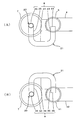
- FIG. 2 is a partial cross-sectional view of the refrigerant condenser shown in FIG. 1, (A) is a partial cross-sectional view of the vicinity of the inflow pipe as viewed from above, and (B) is a partial cross-sectional view of the vicinity of the outflow pipe as viewed from below. It is.
- (A) is the partial cross-sectional view which looked at the inflow pipe vicinity from the upper side
- (B) looked at the outflow pipe vicinity from the lower side. It is a partial cross-sectional view.
- FIG. 1 show a refrigerant condenser according to a first embodiment of the present invention.
- the refrigerant condenser 1 is connected to a condensation core 4 that cools a gaseous refrigerant flowing into a plurality of cooling tubes 6 and condenses it into a liquid refrigerant, and is connected to the upstream side of the condensation core 4 to be supplied with gaseous refrigerant.
- a condensing part 2 comprising a condensing core inlet side header pipe 3 and a condensing core outlet side header pipe 5 connected to the downstream side of the condensing core and collecting liquid refrigerant flowing out of the condensing core.
- the outlet side header pipe 5 is communicated with the liquid receiving part 7 fixed to the condensation core outlet side header pipe 5 by a fixing member (not shown) via the inflow pipe 8.
- a subcooling unit 10 to which liquid refrigerant is supplied from the liquid receiving unit 7 through the outflow pipe 9 is provided at the lower part of the refrigerant condenser 1, and the subcooling unit 10 flows into the plurality of subcooling tubes 14.
- a supercooling core 12 that further cools the liquid refrigerant a supercooling core inlet-side header pipe 11 that communicates with the upstream side of the supercooling core 12 and is supplied with the liquid refrigerant from the liquid receiver 7, and a downstream side of the supercooling core 12
- a supercooling core outlet side header pipe 13 that collects liquid refrigerant flowing out from the supercooling core 12.
- the partition 15 is partitioned between the condensation core outlet side header pipe 5 and the supercooled core inlet side header pipe 11.
- the condensation core outlet side header pipe 5 in order to divide the refrigerant flow path inside the condensation core inlet side header pipe 3, the condensation core outlet side header pipe 5, the supercooling core inlet side header pipe 11, and the supercooling core outlet side header pipe 13, One or more partitions (not shown) different from the partition 15 may be provided. Further, a filter member (not shown) for removing foreign substances in the refrigerant and a drying member (not shown) for removing moisture in the refrigerant may be provided in the liquid receiving unit 7.
- a refrigerant inlet passage block 16 is provided in the condensing core inlet-side header pipe 3, and a refrigerant outlet passage block 17 is provided in the subcooling core outlet-side header pipe 13.
- the gaseous refrigerant introduced from the refrigerant inlet passage block 16 to the refrigerant condenser 1 is cooled by heat exchange with air in the plurality of cooling tubes 6, and then received from the condenser core outlet header pipe 5 through the inlet pipe 8. It is introduced into the part 7 and is separated into gas and liquid in the liquid receiving part 7.
- the liquid refrigerant separated in the liquid receiving part 7 is temporarily stored in the liquid receiving part 7 and then introduced into the supercooling core inlet side header pipe 11 through the outflow pipe 9, via the plurality of supercooling tubes 14. It is further cooled by heat exchange with air and is led out of the refrigerant condenser 1 from the outlet passage block 17.
- the refrigerant condenser 1 of FIG. 1 is substantially flat plate shape, and can be left still with the one surface side (the back side in FIG. 1) in contact with the floor surface.
- the externally exposed portion 34 of the outflow pipe existing in is disposed on the other surface side (front side in FIG. 1) of the refrigerant condenser 1 having a substantially plate shape.
- the inflow pipe 8 and the outflow pipe 9 are assembled to the refrigerant condenser 1 and the liquid receiver 7 fixed thereto, the inflow pipe 8 and the outflow pipe 9 are received from the refrigerant condenser 1 and the liquid receiver.
- the refrigerant condenser 1 can be allowed to stand in a state of being inserted into the vessel 7, and the inflow pipe 8 and the outflow pipe 9 can be brazed to desired positions without using a special holding member. Work and brazing work are facilitated.
- FIG. 2 shows a partially enlarged view in the vicinity of the inlet pipe 8 of the refrigerant condenser 1 of FIG. 3A shows a partial cross-sectional view of the vicinity of the inlet pipe 8 of the refrigerant condenser 1 as viewed from above
- FIG. 3B shows the vicinity of the outlet pipe 9 of the refrigerant condenser 1 below.
- the partial cross-sectional view seen from the side is shown.
- the inflow pipe 8 has a structure including a straight pipe portion 20 and a U-shaped pipe portion 21 extending in a direction perpendicular to the axis of the straight pipe portion 20.
- the downstream portion 25 is inserted into the liquid receiving portion, and the upstream portion 23 of the inflow pipe 8 is inserted into the condensation core outlet side header pipe 5 in parallel with the insertion direction of the downstream portion 25. Further, since the outlet 26 of the inflow pipe is provided above the inlet 22 of the inflow pipe, even when the refrigerant flows out of the inflow pipe 8 in the gas-liquid mixed state and flows into the liquid receiving section 7, it is received. Disturbances in the liquid level of the liquid refrigerant stored in the liquid part 7 can be minimized.
- Inflow pipe 8 in this embodiment is manufactured by bending a pipe into a predetermined shape, and a reduction in manufacturing cost is realized. Further, the insertion portion of the inflow pipe 8 can be fixed by simply joining the pipe and the curved surface, and no special temporary fixing tool is required, so that the temporary assembly work is facilitated and the brazing reliability is improved.
- the outflow pipe 9 has a structure including a straight pipe portion 30 and a U-shaped pipe portion 31 extending in a direction perpendicular to the axis of the straight pipe portion 30, similarly to the inflow pipe 8.
- the upstream portion 33 of the outflow pipe 9 is inserted into the liquid receiving portion 7 and the downstream portion 35 is inserted into the subcooling core inlet header pipe 11 in parallel with the insertion direction of the upstream portion 33.
- the inlet 32 of the outflow pipe 9 is provided in the vicinity of the lower bottom portion of the liquid receiving unit 7, and gas mixing into the liquid refrigerant flowing into the supercooling unit 10 is prevented.
- the outflow pipe 9 is manufactured by bending the pipe into a predetermined shape, and, like the inflow pipe 8, reduction in manufacturing cost, ease of temporary assembly work, and improvement of brazing reliability are realized.
- the inlet 32 of the outflow pipe 9 has a suction structure (not shown) so that the liquid refrigerant stored in the lower portion of the liquid receiving unit 7 flows out preferentially.
- FIG. 4 shows a partial cross-sectional view of the refrigerant condenser according to the second embodiment of the present invention.
- 4A shows a partial cross-sectional view of the vicinity of the inflow pipe 8 of the refrigerant condenser according to the second embodiment of the present invention as viewed from above, and
- FIG. 4B shows the outflow pipe 9.
- the partial cross-sectional view which looked at the vicinity from the lower side is shown.
- the distal end portion 27 of the downstream portion 25 of the inflow pipe 8 is disposed upward along the inner wall surface in the liquid receiving portion 7, and the upstream portion 33 of the outflow pipe 9.
- the tip portion 37 is disposed downward along the inner wall surface in the liquid receiving portion 7, and the other portions have the same configuration as that of the first embodiment of the present invention.
- the distal end portion 27 of the downstream portion of the inflow pipe and the distal end portion 37 of the upstream portion of the outflow pipe are arranged along the inner wall surface in the liquid receiving portion 7, so that they are stored on the bottom surface of the liquid receiving portion 7.
- the disturbance of the liquid level of the liquid refrigerant to be performed can be minimized, and the performance degradation of the refrigerant condenser can be prevented.
- the inlet 32 of the outflow pipe 9 preferably has a suction structure (not shown) so that liquid refrigerant stored in the lower part of the liquid receiving section 7 flows out preferentially. .
- the application of the refrigerant condenser according to the present invention is not particularly limited, but is suitable for use in a vehicle air conditioner that is highly demanded of cost reduction, easy manufacturing, and simplified process.
Landscapes
- Engineering & Computer Science (AREA)
- Physics & Mathematics (AREA)
- Mechanical Engineering (AREA)
- Thermal Sciences (AREA)
- General Engineering & Computer Science (AREA)
- Air-Conditioning For Vehicles (AREA)
Abstract
凝縮コアと凝縮コア入口側ヘッダ管と凝縮コア出口側ヘッダ管とからなる凝縮部と、受液部と、過冷却部とを有し、過冷却部が、過冷却コアと過冷却コア入口側ヘッダ管と過冷却コア出口側ヘッダ管とからなり、流入管が、凝縮コア出口側ヘッダ管内に開口した上流側の一端から受液部内に開口した下流側の他端まで一体に形成され、流出管が、受液部内に開口した上流側の一端から過冷却コア入口側ヘッダ管内に開口した下流側の他端まで一体に形成されていることを特徴とする冷媒凝縮器。ヘッダと受液器との間が流入管によって連通されている冷媒凝縮器において、流入管の構造を改良することにより、製造、組み付けを容易化する。
Description
本発明は、冷媒凝縮器に関し、とくに、受液器と凝縮器との接続構造を改良した、組立が容易な冷媒凝縮器に関する。
冷凍回路に用いられる凝縮器として、気相および液相が混合された冷媒を気液分離する受液器が、ヘッダの側面部に一体的に接合された受液器一体型冷媒凝縮器が知られている。このような受液器一体型冷媒凝縮器においては、一般に、ヘッダを受液器へ接続する冷媒通路が備えられ、それぞれの部品はろう付けによって固定されている。
例えば特許文献1には、凝縮部と過冷却部が一体に形成され、受液器が備えられた冷媒凝縮器について開示されている。この発明においては、凝縮部と受液器の間、および受液器と過冷却部の間を連通する一対の連通路が設けられており、各部材はアルミニウム材で成形され、一体ろう付けにて組付けられている。
しかしながら、特許文献1に開示された発明においては、右ヘッダタンク130と受液器140が直線状の連通路151を介して直接連通されており、それぞれの部材のろう付け時の固定については特に考慮されていない。このため、右ヘッダタンク130と受液器140と連通路151を一体でろう付け接合する際に、これらの組み付け状態を保持する保持治具等が必要となる。また、連通路151、152が直線状であるため流出入回路の設計の自由度が低く、例えばヘッダタンクからの流出部と受液器への流入部を別々の位置に設けることはできない。
そこで本発明の課題は、とくにヘッダと受液器との間を連通する連通部材に関して、部品点数を増加させることなく簡素な構造にしてコストアップを抑えながら、流入出回路を自由に構成でき、製造、組み付けともに容易化された冷媒凝縮器を提供することにある。
上記課題を解決するために、本発明に係る冷媒凝縮器は、複数の冷却チューブ内に流入する気体冷媒を冷却して液体冷媒へと凝縮させる凝縮コアと、該凝縮コアの上流側に連通し前記気体冷媒が供給される凝縮コア入口側ヘッダ管と、前記凝縮コアの下流側に連通し前記凝縮コアから流出する前記液体冷媒を集める凝縮コア出口側ヘッダ管とからなる凝縮部と、該凝縮部から前記液体冷媒が流入管を通して流入する受液部と、該受液部から前記液体冷媒が流出管を通して供給される過冷却部とを有し、
該過冷却部が、複数の過冷却チューブ内に流入する液体冷媒をさらに冷却する過冷却コアと、該過冷却コアの上流側に連通し前記受液部から前記液体冷媒が供給される過冷却コア入口側ヘッダ管と、前記過冷却コアの下流側に連通し前記過冷却コアから流出する液体冷媒を集める過冷却コア出口側ヘッダ管とからなり、
前記流入管が、前記凝縮コア出口側ヘッダ管内に開口した上流側の一端から前記受液部内に開口した下流側の他端まで一体に形成され、
前記流出管が、前記受液部内に開口した上流側の一端から前記過冷却コア入口側ヘッダ管内に開口した下流側の他端まで一体に形成されていることを特徴とするものからなる。
該過冷却部が、複数の過冷却チューブ内に流入する液体冷媒をさらに冷却する過冷却コアと、該過冷却コアの上流側に連通し前記受液部から前記液体冷媒が供給される過冷却コア入口側ヘッダ管と、前記過冷却コアの下流側に連通し前記過冷却コアから流出する液体冷媒を集める過冷却コア出口側ヘッダ管とからなり、
前記流入管が、前記凝縮コア出口側ヘッダ管内に開口した上流側の一端から前記受液部内に開口した下流側の他端まで一体に形成され、
前記流出管が、前記受液部内に開口した上流側の一端から前記過冷却コア入口側ヘッダ管内に開口した下流側の他端まで一体に形成されていることを特徴とするものからなる。
本発明に係る冷媒凝縮器においては、流入管が、凝縮コア出口側ヘッダ管内に開口した上流側の一端から受液部内に開口した下流側の他端まで一体に形成されるとともに、流出管が、受液部内に開口した上流側の一端から過冷却コア入口側ヘッダ管内に開口した下流側の他端まで一体に形成されているので、受液器内の流出入通路と出入口パイプが一体化された簡素な構造にて冷媒の円滑な流動を実現することが可能となる。また、液体冷媒が過冷却部によってさらに冷却されるため、冷媒回路の成績係数の向上が実現できる。
このような本発明に係る冷媒凝縮器においては、前記流入管の下流側部分が前記受液部内に挿通されるとともに、上流側部分が前記凝縮コア出口側ヘッダ管内に前記下流側部分の挿通方向に対し平行に挿通されていることが好ましい。このような構造を採用することにより、前記流入管は2本の平行な挿通部によって支えられた状態となり、ろう付け前の仮組みにおいても簡単な保持部材で組み付けることができ、組み付け作業およびろう付け作業の簡素化が実現できる。
さらに、流入管が受液器の冷媒導入パイプと冷媒流入通路を兼ねるように一体で形成されるとともに、流出管が受液器の冷媒流出通路と冷媒導出パイプを兼ねるように一体で形成されることにより、さらなる組み付け作業の簡素化が実現可能となる。
本発明に係る冷媒凝縮器においては、前記流入管の前記下流側部分の先端部が、前記受液部内の内壁面に沿って上向きに配置されていることが好ましい。これにより、液体冷媒が受液部内の内壁面に沿って受液部へ安定的に流入するようになり、受液部内に貯留される液体冷媒の液面の乱れが最小限に抑えられる。従って、液体冷媒への気体の混入が防止され、冷媒凝縮器の性能低下を防ぐことができる。
前記流入管は、直管部と、該直管部の軸と垂直な方向に延びるU形管部とからなる構造とすることができる。このような単純な形状は、通常のパイプを所望の形状に曲げることで容易に製造することが可能であり、製造コストの低減が実現できる。
前記流入管の出口は、前記流入管の入口よりも上側に設けられていることが好ましい。このような構造によれば、前記流入管へ導入された液体冷媒のうち、前記流入管の出口から溢れた液体冷媒だけが受液部へ流入するようになり、受液部内に貯留される液体冷媒の液面の乱れが最小限に抑えられるため、冷媒凝縮器の性能低下を防ぐことができる。
前記流出管は、上流側部分が前記受液部内に挿通されるとともに下流側部分が前記過冷却コア入口側ヘッダ管内に前記上流側部分の挿通方向に対し平行に挿通されていることが好ましい。このような構造にすれば、前記流出管は2本の平行な挿通部によって支えられるため、組み付け作業およびろう付け作業の簡素化が実現できる。
本発明に係る冷媒凝縮器においては、前記流出管の前記上流側部分の先端部が、前記受液部内の内壁面に沿って下向きに配置されていることが望ましい。これにより、液体冷媒が受液部内の内壁面に沿って受液部へ安定的に流入するようになるため、受液部内に貯留される液体冷媒の液面の乱れが最小限に抑えられ、冷媒凝縮器の性能低下を防ぐことができる。
前記流出管は、直管部と、該直管部の軸と垂直な方向に延びるU形管部とからなる構造とすることができる。このような単純な形状は、通常のパイプを所望の形状に曲げることで容易に製造することが可能であり、製造コストの低減が実現できる。
前記流出管の入口は、前記受液部の下底部近傍に設けられていることが好ましい。前記流出管の入口が、受液部内に貯留される液体冷媒の液面よりも下に配置されることで、過冷却部に流入する液体冷媒への気体の混入が防止され、冷媒凝縮器の性能低下を防ぐことができる。
このように、本発明に係る冷媒凝縮器によれば、流入管が、凝縮コア出口側ヘッダ管内に開口した上流側の一端から受液部内に開口した下流側の他端まで一体に形成されるとともに、流出管が、受液部内に開口した上流側の一端から過冷却コア入口側ヘッダ管内に開口した下流側の他端まで一体に形成されているので、簡素な構造にて冷媒の円滑な流動を実現することが可能となる。
以下に、本発明の望ましい実施の形態を、図面を参照して説明する。
図1、図2、および図3は、本発明の第一の実施態様に係る冷媒凝縮器を示している。図1において、冷媒凝縮器1は、複数の冷却チューブ6内に流入する気体冷媒を冷却して液体冷媒へと凝縮させる凝縮コア4と、凝縮コア4の上流側に連通し気体冷媒が供給される凝縮コア入口側ヘッダ管3と、凝縮コアの下流側に連通し凝縮コアから流出する液体冷媒を集める凝縮コア出口側ヘッダ管5とからなる凝縮部2を上部に有しており、凝縮コア出口側ヘッダ管5は流入管8を経由して、図示しない固定部材により凝縮コア出口側ヘッダ管5に固定された受液部7へ連通されている。冷媒凝縮器1の下部には、受液部7から液体冷媒が流出管9を通して供給される過冷却部10が設けられており、過冷却部10は、複数の過冷却チューブ14内に流入する液体冷媒をさらに冷却する過冷却コア12と、過冷却コア12の上流側に連通し受液部7から液体冷媒が供給される過冷却コア入口側ヘッダ管11と、過冷却コア12の下流側に連通し過冷却コア12から流出する液体冷媒を集める過冷却コア出口側ヘッダ管13とからなる。本実施態様において、凝縮コア出口側ヘッダ管5と過冷却コア入口側ヘッダ管11との間は仕切り15によって区画されている。なお、凝縮コア入口側ヘッダ管3、凝縮コア出口側ヘッダ管5、過冷却コア入口側ヘッダ管11、および過冷却コア出口側ヘッダ管13の内部には、冷媒の流路を区画すべく、仕切り15とは異なる一つ以上の仕切り(図示略)が設けられていてもよい。また、受液部7内には、冷媒内の異物を除去するフィルタ部材(図示略)や冷媒内の水分を除去する乾燥部材(図示略)が設けられていてもよい。
図1、図2、および図3は、本発明の第一の実施態様に係る冷媒凝縮器を示している。図1において、冷媒凝縮器1は、複数の冷却チューブ6内に流入する気体冷媒を冷却して液体冷媒へと凝縮させる凝縮コア4と、凝縮コア4の上流側に連通し気体冷媒が供給される凝縮コア入口側ヘッダ管3と、凝縮コアの下流側に連通し凝縮コアから流出する液体冷媒を集める凝縮コア出口側ヘッダ管5とからなる凝縮部2を上部に有しており、凝縮コア出口側ヘッダ管5は流入管8を経由して、図示しない固定部材により凝縮コア出口側ヘッダ管5に固定された受液部7へ連通されている。冷媒凝縮器1の下部には、受液部7から液体冷媒が流出管9を通して供給される過冷却部10が設けられており、過冷却部10は、複数の過冷却チューブ14内に流入する液体冷媒をさらに冷却する過冷却コア12と、過冷却コア12の上流側に連通し受液部7から液体冷媒が供給される過冷却コア入口側ヘッダ管11と、過冷却コア12の下流側に連通し過冷却コア12から流出する液体冷媒を集める過冷却コア出口側ヘッダ管13とからなる。本実施態様において、凝縮コア出口側ヘッダ管5と過冷却コア入口側ヘッダ管11との間は仕切り15によって区画されている。なお、凝縮コア入口側ヘッダ管3、凝縮コア出口側ヘッダ管5、過冷却コア入口側ヘッダ管11、および過冷却コア出口側ヘッダ管13の内部には、冷媒の流路を区画すべく、仕切り15とは異なる一つ以上の仕切り(図示略)が設けられていてもよい。また、受液部7内には、冷媒内の異物を除去するフィルタ部材(図示略)や冷媒内の水分を除去する乾燥部材(図示略)が設けられていてもよい。
図1において、凝縮コア入口側ヘッダ管3には冷媒の入口通路ブロック16が、過冷却コア出口側ヘッダ管13には冷媒の出口通路ブロック17が、それぞれ設けられている。冷媒の入口通路ブロック16から冷媒凝縮器1へ導入された気体冷媒は、複数の冷却チューブ6において空気との熱交換により冷却された後、凝縮コア出口側ヘッダ管5より流入管8を通じて受液部7内へ導入され、受液部7内において気液分離される。受液部7内において分離された液体冷媒は、受液部7内に一旦貯留された後、流出管9を通じて過冷却コア入口側ヘッダ管11へ導入され、複数の過冷却チューブ14を介した空気との熱交換によりさらに冷却され、出口通路ブロック17より冷媒凝縮器1の外部へ導出される。
なお、図1の冷媒凝縮器1は略平板形状であり、一面側(図1における背面側)が床面に接した状態で静置することが可能である。また、流入管の上流側部分23と流入管の下流側部分25との間に存在する流入管の外部露出部分24、および流出管の上流側部分33と流出管の下流側部分35との間に存在する流出管の外部露出部分34は、略平板形状である冷媒凝縮器1の他面側(図1における正面側)に配置されている。このような構造によれば、流入管8および流出管9を、冷媒凝縮器1とそれに固定された受液器7に組み付ける際に、流入管8および流出管9を冷媒凝縮器1と受液器7に差し込んだ状態で冷媒凝縮器1を静置することが可能となり、特殊な保持部材を用いることなく流入管8および流出管9を所望の位置にろう付けすることができるので、仮組作業およびろう付け作業が容易化される。
図2は、図1の冷媒凝縮器1の流入管8付近における部分拡大図を示している。また、図3の(A)は冷媒凝縮器1の流入管8付近を上側から見た部分横断面図を示しており、図3の(B)は冷媒凝縮器1の流出管9付近を下側から見た部分横断面図を示している。図2および図3の(A)において、流入管8は、直管部20と、直管部20の軸と垂直な方向に延びるU形管部21とからなる構造であり、流入管8の下流側部分25が受液部内に挿通されるとともに、流入管8の上流側部分23が凝縮コア出口側ヘッダ管5内に下流側部分25の挿通方向に対し平行に挿通されている。また、流入管の出口26は、流入管の入口22よりも上側に設けられているので、冷媒が気液混合状態で流入管8から流出して受液部7へ流入する際にも、受液部7内に貯留される液体冷媒の液面の乱れは最小限に抑えられる。本実施態様における流入管8はパイプを所定の形状に曲げることで製造され、製造コストの削減が実現されている。また、流入管8の挿通部はパイプと曲面を単純に接合することで固定でき、特殊な仮固定具を必要としないため、仮組み作業が容易化され、ろう付け信頼性の向上が実現される。
図2および図3の(B)において、流出管9は、流入管8と同様、直管部30と、直管部30の軸と垂直な方向に延びるU形管部31とからなる構造であり、流出管9の上流側部分33が受液部7内に挿通されるとともに下流側部分35が過冷却コア入口側ヘッダ管11内に上流側部分33の挿通方向に対し平行に挿通されている。また、流出管9の入口32は、受液部7の下底部近傍に設けられており、過冷却部10に流入する液体冷媒への気体の混入が防止されている。この流出管9はパイプを所定の形状に曲げることで製造されており、流入管8と同様、製造コストの削減、仮組み作業の容易化、およびろう付け信頼性の向上が実現されている。なお、流出管9の入口32は、受液部7の下部に貯留された液体冷媒を優先的に流出させるべく、吸上げ構造(図示略)となっていることが好ましい。
図4は、本発明の第二の実施態様に係る冷媒凝縮器の部分横断面図を示している。図4の(A)は、本発明の第二の実施態様に係る冷媒凝縮器の流入管8付近を上側から見た部分横断面図を示しており、図4の(B)は流出管9付近を下側から見た部分横断面図を示している。本発明の第二の実施態様においては、流入管8の下流側部分25の先端部27が受液部7内の内壁面に沿って上向きに配置されるとともに、流出管9の上流側部分33の先端部37が、受液部7内の内壁面に沿って下向きに配置されており、その他の部分は本発明の第一の実施態様と同様の構成になっている。このように、流入管の下流側部分の先端部27および流出管の上流側部分の先端部37を受液部7内の内壁面に沿って配置することにより、受液部7の底面に貯留される液体冷媒の液面の乱れが最小限に抑えられ、冷媒凝縮器の性能低下を防ぐことができる。なお、本実施態様においても、流出管9の入口32は、受液部7の下部に貯留された液体冷媒を優先的に流出させるべく、吸上げ構造(図示略)となっていることが好ましい。
本発明に係る冷媒凝縮器の用途はとくに限定されないが、コストダウン、製造の容易化、工程の簡素化の要求が強い車両用空調装置に用いて好適なものである。
1 冷媒凝縮器
2 凝縮部
3 凝縮コア入口側ヘッダ管
4 凝縮コア
5 凝縮コア出口側ヘッダ管
6 冷却チューブ
7 受液部
8 流入管
9 流出管
10 過冷却部
11 過冷却コア入口側ヘッダ管
12 過冷却コア
13 過冷却コア出口側ヘッダ管
14 過冷却チューブ
15 仕切り
16 入口通路ブロック
17 出口通路ブロック
20 流入管の直管部
21 流入管のU形管部
22 流入管の入口
23 流入管の上流側部分
24 流入管の外部露出部分
25 流入管の下流側部分
26 流入管の出口
27 流入管の下流側部分の先端部
30 流出管の直管部
31 流出管のU形管部
32 流出管の入口
33 流出管の上流側部分
34 流出管の外部露出部分
35 流出管の下流側部分
36 流出管の出口
37 流出管の上流側部分の先端部
2 凝縮部
3 凝縮コア入口側ヘッダ管
4 凝縮コア
5 凝縮コア出口側ヘッダ管
6 冷却チューブ
7 受液部
8 流入管
9 流出管
10 過冷却部
11 過冷却コア入口側ヘッダ管
12 過冷却コア
13 過冷却コア出口側ヘッダ管
14 過冷却チューブ
15 仕切り
16 入口通路ブロック
17 出口通路ブロック
20 流入管の直管部
21 流入管のU形管部
22 流入管の入口
23 流入管の上流側部分
24 流入管の外部露出部分
25 流入管の下流側部分
26 流入管の出口
27 流入管の下流側部分の先端部
30 流出管の直管部
31 流出管のU形管部
32 流出管の入口
33 流出管の上流側部分
34 流出管の外部露出部分
35 流出管の下流側部分
36 流出管の出口
37 流出管の上流側部分の先端部
Claims (9)
- 複数の冷却チューブ内に流入する気体冷媒を冷却して液体冷媒へと凝縮させる凝縮コアと、該凝縮コアの上流側に連通し前記気体冷媒が供給される凝縮コア入口側ヘッダ管と、前記凝縮コアの下流側に連通し前記凝縮コアから流出する前記液体冷媒を集める凝縮コア出口側ヘッダ管とからなる凝縮部と、該凝縮部から前記液体冷媒が流入管を通して流入する受液部と、該受液部から前記液体冷媒が流出管を通して供給される過冷却部とを有し、
該過冷却部が、複数の過冷却チューブ内に流入する液体冷媒をさらに冷却する過冷却コアと、該過冷却コアの上流側に連通し前記受液部から前記液体冷媒が供給される過冷却コア入口側ヘッダ管と、前記過冷却コアの下流側に連通し前記過冷却コアから流出する液体冷媒を集める過冷却コア出口側ヘッダ管とからなり、
前記流入管が、前記凝縮コア出口側ヘッダ管内に開口した上流側の一端から前記受液部内に開口した下流側の他端まで一体に形成され、
前記流出管が、前記受液部内に開口した上流側の一端から前記過冷却コア入口側ヘッダ管内に開口した下流側の他端まで一体に形成されていることを特徴とする冷媒凝縮器。 - 前記流入管は、下流側部分が前記受液部内に挿通されるとともに、上流側部分が前記凝縮コア出口側ヘッダ管内に前記下流側部分の挿通方向に対し平行に挿通されている、請求項1に記載の冷媒凝縮器。
- 前記流入管の前記下流側部分の先端部が、前記受液部内の内壁面に沿って上向きに配置されている、請求項1または2に記載の冷媒凝縮器。
- 前記流入管が、直管部と、該直管部の軸と垂直な方向に延びるU形管部とからなる、請求項1~3のいずれかに記載の冷媒凝縮器。
- 前記流入管の出口が、前記流入管の入口よりも上側に設けられている、請求項1~4のいずれかに記載の冷媒凝縮器。
- 前記流出管は、上流側部分が前記受液部内に挿通されるとともに下流側部分が前記過冷却コア入口側ヘッダ管内に前記上流側部分の挿通方向に対し平行に挿通されている、請求項1~5のいずれかに記載の冷媒凝縮器。
- 前記流出管の前記上流側部分の先端部が、前記受液部内の内壁面に沿って下向きに配置されている、請求項1~6のいずれかに記載の冷媒凝縮器。
- 前記流出管が、直管部と、該直管部の軸と垂直な方向に延びるU形管部とからなる、請求項1~7のいずれかに記載の冷媒凝縮器。
- 前記流出管の入口が、前記受液部の下底部近傍に設けられている、請求項1~8のいずれかに記載の冷媒凝縮器。
Applications Claiming Priority (2)
| Application Number | Priority Date | Filing Date | Title |
|---|---|---|---|
| JP2010-269333 | 2010-12-02 | ||
| JP2010269333A JP5430542B2 (ja) | 2010-12-02 | 2010-12-02 | 冷媒凝縮器 |
Publications (1)
| Publication Number | Publication Date |
|---|---|
| WO2012073643A1 true WO2012073643A1 (ja) | 2012-06-07 |
Family
ID=46171592
Family Applications (1)
| Application Number | Title | Priority Date | Filing Date |
|---|---|---|---|
| PCT/JP2011/075376 Ceased WO2012073643A1 (ja) | 2010-12-02 | 2011-11-04 | 冷媒凝縮器 |
Country Status (2)
| Country | Link |
|---|---|
| JP (1) | JP5430542B2 (ja) |
| WO (1) | WO2012073643A1 (ja) |
Cited By (2)
| Publication number | Priority date | Publication date | Assignee | Title |
|---|---|---|---|---|
| CN103438621A (zh) * | 2013-08-28 | 2013-12-11 | 广东志高空调有限公司 | 一种可变流路空调冷凝器 |
| CN104121425A (zh) * | 2013-12-18 | 2014-10-29 | 东风柳州汽车有限公司 | 汽车空调冷凝器 |
Families Citing this family (2)
| Publication number | Priority date | Publication date | Assignee | Title |
|---|---|---|---|---|
| CN104501480B (zh) * | 2014-12-26 | 2017-03-15 | 长城汽车股份有限公司 | 车辆及其冷凝器 |
| JP6481668B2 (ja) | 2015-12-10 | 2019-03-13 | 株式会社デンソー | 冷凍サイクル装置 |
Citations (8)
| Publication number | Priority date | Publication date | Assignee | Title |
|---|---|---|---|---|
| JPH109713A (ja) * | 1996-06-24 | 1998-01-16 | Denso Corp | 冷媒凝縮装置、および冷媒凝縮器 |
| JP2000314574A (ja) * | 1999-04-28 | 2000-11-14 | Showa Alum Corp | レシーバータンク付きコンデンサ |
| JP2000346491A (ja) * | 1999-03-30 | 2000-12-15 | Calsonic Kansei Corp | 凝縮器 |
| JP2001124439A (ja) * | 1999-10-25 | 2001-05-11 | Showa Alum Corp | 過冷却器付きコンデンサ |
| JP2002162134A (ja) * | 2000-11-20 | 2002-06-07 | Denso Corp | 冷凍サイクル装置 |
| JP2004218989A (ja) * | 2003-01-17 | 2004-08-05 | Japan Climate Systems Corp | 受液器の取付構造 |
| JP2006207920A (ja) * | 2005-01-27 | 2006-08-10 | Denso Corp | 熱交換器の接続構造 |
| JP2008281326A (ja) * | 2007-04-11 | 2008-11-20 | Calsonic Kansei Corp | 冷凍装置及び該冷凍装置に用いる熱交換器 |
-
2010
- 2010-12-02 JP JP2010269333A patent/JP5430542B2/ja not_active Expired - Fee Related
-
2011
- 2011-11-04 WO PCT/JP2011/075376 patent/WO2012073643A1/ja not_active Ceased
Patent Citations (8)
| Publication number | Priority date | Publication date | Assignee | Title |
|---|---|---|---|---|
| JPH109713A (ja) * | 1996-06-24 | 1998-01-16 | Denso Corp | 冷媒凝縮装置、および冷媒凝縮器 |
| JP2000346491A (ja) * | 1999-03-30 | 2000-12-15 | Calsonic Kansei Corp | 凝縮器 |
| JP2000314574A (ja) * | 1999-04-28 | 2000-11-14 | Showa Alum Corp | レシーバータンク付きコンデンサ |
| JP2001124439A (ja) * | 1999-10-25 | 2001-05-11 | Showa Alum Corp | 過冷却器付きコンデンサ |
| JP2002162134A (ja) * | 2000-11-20 | 2002-06-07 | Denso Corp | 冷凍サイクル装置 |
| JP2004218989A (ja) * | 2003-01-17 | 2004-08-05 | Japan Climate Systems Corp | 受液器の取付構造 |
| JP2006207920A (ja) * | 2005-01-27 | 2006-08-10 | Denso Corp | 熱交換器の接続構造 |
| JP2008281326A (ja) * | 2007-04-11 | 2008-11-20 | Calsonic Kansei Corp | 冷凍装置及び該冷凍装置に用いる熱交換器 |
Cited By (2)
| Publication number | Priority date | Publication date | Assignee | Title |
|---|---|---|---|---|
| CN103438621A (zh) * | 2013-08-28 | 2013-12-11 | 广东志高空调有限公司 | 一种可变流路空调冷凝器 |
| CN104121425A (zh) * | 2013-12-18 | 2014-10-29 | 东风柳州汽车有限公司 | 汽车空调冷凝器 |
Also Published As
| Publication number | Publication date |
|---|---|
| JP2012117777A (ja) | 2012-06-21 |
| JP5430542B2 (ja) | 2014-03-05 |
Similar Documents
| Publication | Publication Date | Title |
|---|---|---|
| JP5501242B2 (ja) | コンデンサ | |
| JP5142109B2 (ja) | エバポレータ | |
| US9791190B2 (en) | Condenser | |
| JP6722242B2 (ja) | 凝縮器 | |
| US10337808B2 (en) | Condenser | |
| US10094601B2 (en) | Condenser | |
| JP2015200478A (ja) | コンデンサ | |
| JP5430542B2 (ja) | 冷媒凝縮器 | |
| CN102037305B (zh) | 热交换器和包括这种交换器的集成空调组件 | |
| CN107606825B (zh) | 冷凝器 | |
| JP2008008577A (ja) | 冷凍サイクル | |
| WO2001001051A1 (en) | Refrigerant condenser | |
| US20220136785A1 (en) | Heat exchanger | |
| JP2001174103A (ja) | 冷媒凝縮器 | |
| JP2008267753A (ja) | 熱交換器 | |
| JP2007078292A (ja) | 熱交換器および複式熱交換器 | |
| JP5904738B2 (ja) | 二相熱交換器とヘッダーとの組立体 | |
| JP2006266570A (ja) | 車両用冷却装置 | |
| JP2010065880A (ja) | コンデンサ | |
| JP2013029257A (ja) | コンデンサ | |
| KR200279353Y1 (ko) | 수액기일체형응축기 | |
| JP2003254641A (ja) | 冷凍システム、冷凍サイクル用凝縮装置及びその装置の冷媒出口構造 | |
| JP2008256234A (ja) | エバポレータ | |
| JP2008267752A (ja) | 熱交換器 | |
| JP2004190955A (ja) | コンデンサ |
Legal Events
| Date | Code | Title | Description |
|---|---|---|---|
| 121 | Ep: the epo has been informed by wipo that ep was designated in this application |
Ref document number: 11844057 Country of ref document: EP Kind code of ref document: A1 |
|
| NENP | Non-entry into the national phase |
Ref country code: DE |
|
| 122 | Ep: pct application non-entry in european phase |
Ref document number: 11844057 Country of ref document: EP Kind code of ref document: A1 |