WO2012073619A1 - 画像表示装置 - Google Patents
画像表示装置 Download PDFInfo
- Publication number
- WO2012073619A1 WO2012073619A1 PCT/JP2011/074613 JP2011074613W WO2012073619A1 WO 2012073619 A1 WO2012073619 A1 WO 2012073619A1 JP 2011074613 W JP2011074613 W JP 2011074613W WO 2012073619 A1 WO2012073619 A1 WO 2012073619A1
- Authority
- WO
- WIPO (PCT)
- Prior art keywords
- image display
- display device
- unit
- photovoltaic
- main body
- Prior art date
- Legal status (The legal status is an assumption and is not a legal conclusion. Google has not performed a legal analysis and makes no representation as to the accuracy of the status listed.)
- Ceased
Links
Images






Classifications
-
- F—MECHANICAL ENGINEERING; LIGHTING; HEATING; WEAPONS; BLASTING
- F21—LIGHTING
- F21L—LIGHTING DEVICES OR SYSTEMS THEREOF, BEING PORTABLE OR SPECIALLY ADAPTED FOR TRANSPORTATION
- F21L4/00—Electric lighting devices with self-contained electric batteries or cells
- F21L4/08—Electric lighting devices with self-contained electric batteries or cells characterised by means for in situ recharging of the batteries or cells
-
- G—PHYSICS
- G09—EDUCATION; CRYPTOGRAPHY; DISPLAY; ADVERTISING; SEALS
- G09F—DISPLAYING; ADVERTISING; SIGNS; LABELS OR NAME-PLATES; SEALS
- G09F9/00—Indicating arrangements for variable information in which the information is built-up on a support by selection or combination of individual elements
- G09F9/30—Indicating arrangements for variable information in which the information is built-up on a support by selection or combination of individual elements in which the desired character or characters are formed by combining individual elements
- G09F9/35—Indicating arrangements for variable information in which the information is built-up on a support by selection or combination of individual elements in which the desired character or characters are formed by combining individual elements being liquid crystals
-
- H—ELECTRICITY
- H02—GENERATION; CONVERSION OR DISTRIBUTION OF ELECTRIC POWER
- H02S—GENERATION OF ELECTRIC POWER BY CONVERSION OF INFRARED RADIATION, VISIBLE LIGHT OR ULTRAVIOLET LIGHT, e.g. USING PHOTOVOLTAIC [PV] MODULES
- H02S20/00—Supporting structures for PV modules
-
- H—ELECTRICITY
- H02—GENERATION; CONVERSION OR DISTRIBUTION OF ELECTRIC POWER
- H02S—GENERATION OF ELECTRIC POWER BY CONVERSION OF INFRARED RADIATION, VISIBLE LIGHT OR ULTRAVIOLET LIGHT, e.g. USING PHOTOVOLTAIC [PV] MODULES
- H02S20/00—Supporting structures for PV modules
- H02S20/10—Supporting structures directly fixed to the ground
-
- H—ELECTRICITY
- H02—GENERATION; CONVERSION OR DISTRIBUTION OF ELECTRIC POWER
- H02S—GENERATION OF ELECTRIC POWER BY CONVERSION OF INFRARED RADIATION, VISIBLE LIGHT OR ULTRAVIOLET LIGHT, e.g. USING PHOTOVOLTAIC [PV] MODULES
- H02S20/00—Supporting structures for PV modules
- H02S20/30—Supporting structures being movable or adjustable, e.g. for angle adjustment
-
- F—MECHANICAL ENGINEERING; LIGHTING; HEATING; WEAPONS; BLASTING
- F24—HEATING; RANGES; VENTILATING
- F24S—SOLAR HEAT COLLECTORS; SOLAR HEAT SYSTEMS
- F24S25/00—Arrangement of stationary mountings or supports for solar heat collector modules
- F24S25/10—Arrangement of stationary mountings or supports for solar heat collector modules extending in directions away from a supporting surface
-
- Y—GENERAL TAGGING OF NEW TECHNOLOGICAL DEVELOPMENTS; GENERAL TAGGING OF CROSS-SECTIONAL TECHNOLOGIES SPANNING OVER SEVERAL SECTIONS OF THE IPC; TECHNICAL SUBJECTS COVERED BY FORMER USPC CROSS-REFERENCE ART COLLECTIONS [XRACs] AND DIGESTS
- Y02—TECHNOLOGIES OR APPLICATIONS FOR MITIGATION OR ADAPTATION AGAINST CLIMATE CHANGE
- Y02E—REDUCTION OF GREENHOUSE GAS [GHG] EMISSIONS, RELATED TO ENERGY GENERATION, TRANSMISSION OR DISTRIBUTION
- Y02E10/00—Energy generation through renewable energy sources
- Y02E10/50—Photovoltaic [PV] energy
Definitions
- the present invention relates to an image display device that displays an image.
- Patent Document 1 discloses an image display device including a sealed structure that prevents entry of water and dust and a cooling structure that suppresses an increase in temperature in order to cope with outdoor installation.
- Patent Document 2 discloses an image display device that is driven by electric power obtained by power generation of a solar cell.
- FIG. 1 of Patent Document 2 discloses a solar cell provided on a side surface of a table on which an image display device is installed, and a daylighting device for causing light to efficiently enter the solar cell.
- An image display device includes: A photovoltaic unit that generates electricity by being irradiated with light; A display unit that displays an image using power obtained by power generation of the photovoltaic unit; A main body provided with a display unit, A photovoltaic unit is provided vertically above the main body.
- An image display device includes: A photovoltaic unit that generates electricity by being irradiated with light; A display unit that displays an image using power obtained by power generation of the photovoltaic unit; A main body provided with a display, With The photovoltaic unit provided vertically above the main body can take a plurality of rotational states.
- FIG. 3 is a front perspective view of the image display device 1.
- FIG. 3 is a rear perspective view of the image display device 1. These are side views of the image display apparatus 1.
- FIG. 3 is a front perspective view of the image display device 100.
- FIG. 3 is a rear perspective view of the image display apparatus 100. These are side views of the image display device 100.
- FIG. 4 is a plan view showing a flat plate member 131 of a support portion 130 provided in the image display device 100. These are back perspective views which show the other example of attachment of the photovoltaic part in the image display apparatus 100.
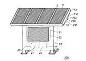
- FIG. FIG. 4 is a front perspective view of the image display device 200.
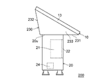
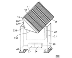
- FIG. 4 is a rear perspective view of the image display device 200. These are side views of the image display apparatus 200.
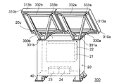
- FIG. 4 is a rear perspective view of the image display device 300. These are back perspective views which show the other example of attachment of the photovoltaic part in the image display apparatus 300.
- FIG. FIG. 6 is a rear perspective view of the image display device 400. These are side views of the image display device 400. These are back perspective views which show the other example of attachment of the photovoltaic part in the image display apparatus 400.
- FIG. 4 is a rear perspective view of the image display device 300.
- FIG. 6 is a rear perspective view of the image display device 400. These are side views of the image display device 400.
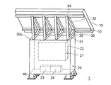
- FIG. 1 is a front perspective view of the image display device 1
- FIG. 2 is a rear perspective view of the image display device 1.
- FIG. 3 is a side view of the image display device 1.
- the image display device 1 includes a photovoltaic power generation unit 10, a rectangular parallelepiped main body unit 20, and a support unit 30 that is disposed on the upper surface of the main body unit 20 and supports the photovoltaic power generation unit 10. And leg portions 40 which are provided at the four corners of the lower surface of the main body portion 20 and support the image display device 1.
- the photovoltaic unit 10 is provided on the installation table 13, four photovoltaic panels 11 that convert the energy of irradiated light into electric power, a flat installation table 13 for arranging these photovoltaic panels 11, and the installation table 13. And a fixing portion 12 for fixing each photovoltaic panel 11.
- the fixing portion 12 is fixed to the installation base 13 with bolts, nuts, and the like, and the photovoltaic panel 11 is fixed by pressing the end of the photovoltaic panel 11 against the installation base 13.
- the main unit 20 charges a power supplied from the display unit 21 that displays an image, a window 22 that is provided on the front surface of the main unit 20 to make the display unit 21 visible, and the photovoltaic unit 10. And a storage battery 23 for supplying power to the display unit 21 and the like, and a control device 24 for controlling charging of the storage battery 23 and the like.
- a fan for cooling the inside of the main body 20 may be provided.
- the display unit 21 includes, for example, an LCD panel and is driven by the electric power obtained by the photovoltaic unit 10.
- the window portion 22 is made of a transparent member such as glass, and is provided for the purpose of protecting the LCD panel from external impacts, water, dust, or the like. Further, a touch panel may be provided on the front side of the display unit 21.
- the power storage unit 23 charges the power obtained by the photovoltaic unit 10. For example, of the generated power, the power that is not consumed by the image display device 1 is charged. On the other hand, the storage battery 23 discharges as needed to supply power to the image display device 1 when the photovoltaic unit 10 does not generate power, such as at night or in cloudy weather.
- the support unit 30 is disposed on the upper surface 20 u of the main body unit 20 and supports the photovoltaic unit 10. In consideration of the incident angle of sunlight, the support part 30 is formed so that the surface of the photovoltaic unit 10 is at a predetermined angle with respect to the upper surface 20 u of the main body part 20.
- the support part 30 is provided with the 1st member 31, the 2nd member 32, the 3rd member 33, and the 4th member 34 which are rod-shaped members, respectively, and four such support parts 30 are provided, It is provided on the upper part of the main body 20.
- the first member 31 is fixed to the upper surface 20 u of the main body 20.
- the second member 32 is fixed to the back surface of the installation base 13 of the photovoltaic unit 10.
- the third member 33 connects the lower end sides of the first member 31 and the second member 32.
- the fourth member 34 connects the first member 31 and the upper end side of the second member 32.
- Each of the 1st member 31, the 2nd member 32, the 3rd member 33, and the 4th member 34 is rod shape.
- first member 31, the second member 32, the third member 33, and the fourth member 34 forming one set are included in substantially the same surface (a surface perpendicular to the upper surface of the main body 20).
- the photovoltaic power generation unit 10 that has become large in order to drive the display device is disposed above the main body unit 20, the installation area of the image display device 1 can be reduced, The degree of freedom can be improved.
- the storage battery 23 and the control device 24 are provided below the display unit 21.
- the display part 21 is arrange
- the power storage unit 23 and the control device 24 can be arranged in an empty space below the display unit 21.
- the leg portion 40 may not be provided, and the main body portion 20 may be installed on the ground.
- positioning and fixing method of the photovoltaic panel 11 are only examples, and may be based on another method.
- the example using four sets of support parts 30 is shown in the above example, the number of sets is not limited to four.
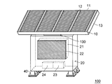
- FIG. 4 is a front perspective view
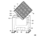
- FIG. 5 is a rear perspective view
- FIG. 6 is a side view.
- the image display device 100 according to the present embodiment is different from the image display device according to the first embodiment in the structure of the support portion 130.
- the support unit 130 includes one flat plate member 131, four rod-shaped members 132, and four column members 133.
- the flat plate member 131 is a flat plate member fixed to the upper surface 20 u of the main body 20.
- Each rod-like member 132 is fixed on the back surface of the installation base 13 of the photovoltaic unit 10 in such a manner as to form one side of a quadrangle similar to the photovoltaic unit 10.
- Each column member 133 connects the vicinity of the four corners of the flat plate member 131 and the corners of the above-described rectangle.
- the column members 133 are connected such that the distance between the four corners of the flat plate member 131 and the four corners of the rod-shaped member 132 is the shortest.
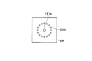
- FIG. 7 is a plan view showing a lower surface portion of the support portion 130.
- a guide hole 131a is provided in the center of the flat plate member 131. Further, each of the 16 mounting holes 131b is provided concentrically with the guide hole 131a as the center.
- the upper surface 20u of the main body 20 is provided with a screw hole c, and the position of the support portion 130 on the upper surface 20u can be fixed by passing the screw through the screw hole c and the guide hole 131a.
- 16 screw holes p are concentrically provided around the screw hole c on the upper surface 20u. Accordingly, the support portion 130 is rotated about the position of the guide hole 131a, and the screw is passed through each of the 16 mounting holes 131b and each of the 16 screw holes p, thereby installing the support portion 130.
- the direction can be determined. Thereby, the direction of only the photovoltaic part 10 can be changed, without changing the direction of the display apparatus 1 main body.
- the photovoltaic unit 10 can be installed in the orientation shown in FIG. 8 by changing the orientation of the flat member 131 by 90 °.
- the arrangement of the guide holes 131a and the mounting holes 131b in the flat plate member 131 may be other than that shown in FIG.
- FIG. 9 is a front perspective view
- FIG. 10 is a rear perspective view
- FIG. 11 is a side view.
- the image display device 200 is different from the image display device 1 of the first embodiment described above in the structure of the support unit 230. Hereinafter, the description will be made focusing on the support portion 230.
- the support unit 230 includes a lower surface 231, one rear surface 232, and two side surfaces 233. *
- the lower surface 231 has a rectangular shape having four sides and is fixed to the upper surface 20 u of the main body 20. Further, the entire one side of the four sides is in contact with the back surface of the photovoltaic unit 10.
- the back surface 232 is also a rectangular shape having four sides, and the entire upper side is in contact with the back surface of the photovoltaic unit 10, and the entire lower side is in contact with the lower surface 231.
- Each of the two side surfaces 233 has a triangular shape surrounded by the back surface, the bottom surface 231 and the back surface 232 of the photovoltaic unit 10.
- the support part 230 (the lower surface part 231, the back surface part 232, and the side surface part 233) and the photovoltaic unit 10 form a pentahedron as a whole.
- a single guide hole and a plurality of mounting holes provided concentrically around the guide hole can be fixed to the upper surface of the main body 20 by providing the lower surface 231. And the attachment direction of the lower surface part 231 can be changed.
- the screw cannot be screwed from the upper side like the image display device 100 because of the structure. Can be fixed.
- a protrusion may be provided on the upper surface 20u, and a guide hole or the like may be inserted into the protrusion to be fixed.
- the direction of the photovoltaic unit 10 is changed by 90 ° with respect to the example of FIG. Can be fixed.
- the image display device 200 has a structure in which the support unit 230 forms a polyhedron with the photovoltaic unit 10 by combining flat plate materials. Therefore, the influence of wind (air flow) such as wind noise and wind pressure can be reduced by air rectification.
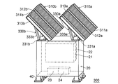
- FIG. 13 is a rear perspective view of the image display device 300.
- the image display apparatus 300 includes a photovoltaic unit 310 a and a support unit 330 a that supports the photovoltaic unit 310 a, a photovoltaic unit 310 b, and a support unit 330 b that supports the photovoltaic unit 310 a.
- the support portions 330a and 330b are respectively disposed on the upper surface 20u of the main body portion 20. That is, it differs from the image display device 100 of the second embodiment in that there are a plurality of photovoltaic power generation units and support units.
- the photovoltaic unit 310a includes two photovoltaic panels 311a, an installation table 313a for arranging these photovoltaic panels, and a fixing unit 312a for fixing each photovoltaic panel provided on the installation table 313a.
- the photovoltaic unit 310b also includes two photovoltaic panels 311b, an installation base 313b, and a fixing unit 312b.
- the support part 330a is provided with the one flat plate member 331a, the four rod-shaped members 332a, and the four pillar members 333a like the support part 130 of 2nd Embodiment.
- the support portion 330b includes one flat plate member 331b, four rod-shaped members 332b, and four column members 333b.
- Each flat plate member 331a, 331b is provided with a guide hole and a mounting hole as shown in FIG. Thereby, the direction of photovoltaic units 310a and 310b can be changed.
- the direction of each photovoltaic power generation unit can be fixed in a state changed by 90 °.
- four photovoltaic panels are integrated, and when the orientation of the photovoltaic unit is changed as it is, the photovoltaic unit protrudes from the main body of the image display device.
- the photovoltaic power generation unit is divided into two, even if the orientation of the photovoltaic power generation unit is changed, it does not protrude from the main body of the image display device, and as a result, space saving can be achieved. it can.
- the photovoltaic power generation unit and the support unit of the image display device 200 of the third embodiment may be divided into two to have the same configuration as that of the present embodiment.
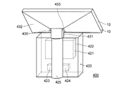
- FIG. 15 is a rear perspective view of the image display device 400
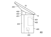
- FIG. 16 is a side view thereof.
- the image display device 400 includes a photovoltaic power generation unit 10, a main body unit 420, and a support unit 430.
- the main body 420 includes a display 421, a window 422, a storage battery 423, a control device 424, and a pillar 425. In this embodiment, it differs from the image display apparatus 200 of 3rd Embodiment by the point provided with the pillar part 425.
- FIG. 1 A photovoltaic power generation unit 10
- the main body 420 includes a display 421, a window 422, a storage battery 423, a control device 424, and a pillar 425. In this embodiment, it differs from the image display apparatus 200 of 3rd Embodiment by the point provided with the pillar part 425.
- the column part 425 is a columnar member having a substantially semicircular cross section.
- the column part 425 is disposed on the back side of the main body part 420.
- the upper surface of the column portion 425 is disposed at a position that is substantially the same height as the upper surface of the main body portion 420.
- the lower surface of the column portion 425 is disposed at a position that is substantially the same height as the lower surface of the main body portion 420.
- the lower side of the column part 425 may be buried in the ground.
- the support portion 430 that supports the photovoltaic power generation portion includes a column portion 431, a side surface portion 432, and a bottom portion 433.
- the column part 431 is a hexahedral column member, the upper surface, the lower surface, the front surface (these three surfaces are hidden in FIG. 15 and not shown), and the back surface is rectangular, and the two side surfaces are trapezoidal. is there. Also, the back is larger than the front.
- the column portion 431 has an upper surface inclined with respect to the lower surface.
- the lower surface of the column part 431 is arranged in such a manner as to ride on the upper surface of the main body part 420.
- the bottom portion 433 is disposed on the top surface of the column portion 431. Thereby, it is possible to indicate the photovoltaic unit at an angle inclined from the ground.
- the side surface portion 432 is divided into four surfaces, and a quadrangular pyramid is formed by these four surfaces, the bottom portion 433, and the back surface of the photovoltaic unit.
- the column part 431 is fixed to the upper surface of the main body part 420 and can change its orientation (FIG. 17).
- the shape of the image display device is not limited to a rectangular parallelepiped, and may be other shapes.
Landscapes
- Engineering & Computer Science (AREA)
- Physics & Mathematics (AREA)
- General Physics & Mathematics (AREA)
- Theoretical Computer Science (AREA)
- Chemical & Material Sciences (AREA)
- Crystallography & Structural Chemistry (AREA)
- General Engineering & Computer Science (AREA)
- Devices For Indicating Variable Information By Combining Individual Elements (AREA)
- Photovoltaic Devices (AREA)
- Illuminated Signs And Luminous Advertising (AREA)
Abstract
Description
光が照射されることで発電する光発電部と、
光発電部の発電により得られた電力を用いて画像を表示する表示部と、
表示部が設けられる本体部と、を備え、
本体部の鉛直上方に、光発電部が設けられることを特徴とする。
光が照射されることで発電する光発電部と、
光発電部の発電により得られた電力を用いて画像を表示する表示部と、
表示部が設けられる本体部と、
を備え、
本体部の鉛直上方に設けられる光発電部が、複数の回転状態を取り得ることを特徴とする。
最初に、本発明の第1実施形態に係る画像表示装置1について、図面を参照して説明する。図1は、画像表示装置1の前方斜視図であり、図2は画像表示装置1の後方斜視図である。また、図3は、画像表示装置1の側面図である。
次に、本発明の第2実施形態に係る画像表示装置100について、図面を参照して説明する。図4は前方斜視図、図5は後方斜視図、図6は側面図である。
次に、第3実施形態の画像表示装置200について、図面を参照して説明する。図9は前方斜視図、図10は後方斜視図、図11は側面図である。
次に、第4実施形態の画像表示装置300について、図面を参照して説明する。図13画像表示装置300の後方斜視図である。
次に、第5実施形態の画像表示装置400について、図面を参照して説明する。図15は、画像表示装置400の背面斜視図であり、図16は、その側面図である。
Claims (14)
- 光が照射されることで発電する光発電部と、
光発電部の発電により得られた電力を用いて画像を表示する表示部と、
表示部が設けられる本体部と、を備え、
本体部の鉛直上方に、光発電部が設けられることを特徴とする画像表示装置。 - 本体部の上面に設けられ、略平板状の光発電部を水平面に対して傾斜した状態で支持する支持部をさらに備えることを特徴とする請求項1に記載の画像表示装置。
- 本体部の上面に設けられ、略平板状の光発電部を水平面に対して所定の角度で支持する支持部をさらに備え、
光発電部の水平面に対する角度が、画像表示装置の設置を予定する地域の緯度に応じた角度であることを特徴とする請求項1に記載の画像表示装置。 - 本体部の鉛直方向の射影面積が、光発電部の鉛直方向の射影面積よりも小さいことを特徴とする請求項1に記載の画像表示装置。
- 光発電部の鉛直方向の射影内に、本体部の鉛直方向の射影が包含されることを特徴とする請求項4に記載の画像表示装置。
- 光発電部の発電により得られた電力を充電し、放電により画像表示装置に電力を供給する蓄電部をさらに備え、
蓄電部は、表示部の鉛直下方に設けられることを特徴とする請求項1に記載の画像表示装置。 - 光が照射されることで発電する光発電部と、
光発電部の発電により得られた電力を用いて画像を表示する表示部と、
表示部が設けられる本体部と、
を備え、
本体部の鉛直上方に設けられる光発電部が、複数の回転状態を取り得ることを特徴とする画像表示装置。 - 略平板状の光発電部を水平面に対して傾斜した状態で支持する支持部をさらに備え、
本体部の上面及び支持部の下面が、取付具によって固定され、
本体部の上面及び支持部の下面の少なくとも一方の、取付具を取付可能な位置が、回転対称の位置であることを特徴とする請求項7に記載の画像表示装置。 - 略平板状の光発電部を水平面に対して傾斜した状態で支持する支持部をさらに備え、
本体部の上面で、支持部が回転自在に支持されることを特徴とする請求項7に記載の画像表示装置。 - 支持部が、棒状の材料を組み合わせた構造を有することを特徴とする請求項8に記載の画像表示装置。
- 支持部が、棒状の材料を組み合わせた構造を有することを特徴とする請求項9に記載の画像表示装置。
- 支持部が、平板状の材料を組み合わせて光発電部と多面体を成す構造を有することを特徴とする請求項8に記載の画像表示装置。
- 支持部が、平板状の材料を組み合わせて光発電部と多面体を成す構造を有することを特徴とする請求項9に記載の画像表示装置。
- 本体部の上面に、複数の支持部及び光発電部が設けられることを特徴とする請求項7に記載の画像表示装置。
Priority Applications (3)
| Application Number | Priority Date | Filing Date | Title |
|---|---|---|---|
| JP2012546741A JPWO2012073619A1 (ja) | 2010-11-30 | 2011-10-26 | 画像表示装置 |
| US13/823,541 US20130170193A1 (en) | 2010-11-30 | 2011-10-26 | Image display device |
| CN2011800417071A CN103080993A (zh) | 2010-11-30 | 2011-10-26 | 图像显示装置 |
Applications Claiming Priority (4)
| Application Number | Priority Date | Filing Date | Title |
|---|---|---|---|
| JP2010266333 | 2010-11-30 | ||
| JP2010266352 | 2010-11-30 | ||
| JP2010-266333 | 2010-11-30 | ||
| JP2010-266352 | 2010-11-30 |
Publications (1)
| Publication Number | Publication Date |
|---|---|
| WO2012073619A1 true WO2012073619A1 (ja) | 2012-06-07 |
Family
ID=46171570
Family Applications (1)
| Application Number | Title | Priority Date | Filing Date |
|---|---|---|---|
| PCT/JP2011/074613 Ceased WO2012073619A1 (ja) | 2010-11-30 | 2011-10-26 | 画像表示装置 |
Country Status (4)
| Country | Link |
|---|---|
| US (1) | US20130170193A1 (ja) |
| JP (1) | JPWO2012073619A1 (ja) |
| CN (1) | CN103080993A (ja) |
| WO (1) | WO2012073619A1 (ja) |
Cited By (1)
| Publication number | Priority date | Publication date | Assignee | Title |
|---|---|---|---|---|
| JP2018013516A (ja) * | 2016-07-19 | 2018-01-25 | 東京電力ホールディングス株式会社 | サイネージ装置 |
Families Citing this family (3)
| Publication number | Priority date | Publication date | Assignee | Title |
|---|---|---|---|---|
| CN105070212A (zh) * | 2015-08-13 | 2015-11-18 | 方小玲 | 一种用于比赛场外播放比赛的新型全彩太阳能led显示屏 |
| CA3065203A1 (en) * | 2019-12-16 | 2021-06-16 | Big Digital Corp. | Popup video display system |
| CN113327512B (zh) * | 2021-05-11 | 2022-05-17 | 山东水利职业学院 | 一种基于bim的建筑工程数据采集模拟设备 |
Citations (3)
| Publication number | Priority date | Publication date | Assignee | Title |
|---|---|---|---|---|
| JPH09325708A (ja) * | 1996-05-31 | 1997-12-16 | Sanyo Electric Co Ltd | 太陽電池型表示装置 |
| JP2005321737A (ja) * | 2004-05-11 | 2005-11-17 | Fuji Xerox Co Ltd | 画像表示装置 |
| JP2010191054A (ja) * | 2009-02-17 | 2010-09-02 | Mk Seiko Co Ltd | 表示装置 |
Family Cites Families (1)
| Publication number | Priority date | Publication date | Assignee | Title |
|---|---|---|---|---|
| JP2012118207A (ja) * | 2010-11-30 | 2012-06-21 | Sanyo Electric Co Ltd | 表示システム |
-
2011
- 2011-10-26 US US13/823,541 patent/US20130170193A1/en not_active Abandoned
- 2011-10-26 JP JP2012546741A patent/JPWO2012073619A1/ja active Pending
- 2011-10-26 WO PCT/JP2011/074613 patent/WO2012073619A1/ja not_active Ceased
- 2011-10-26 CN CN2011800417071A patent/CN103080993A/zh active Pending
Patent Citations (3)
| Publication number | Priority date | Publication date | Assignee | Title |
|---|---|---|---|---|
| JPH09325708A (ja) * | 1996-05-31 | 1997-12-16 | Sanyo Electric Co Ltd | 太陽電池型表示装置 |
| JP2005321737A (ja) * | 2004-05-11 | 2005-11-17 | Fuji Xerox Co Ltd | 画像表示装置 |
| JP2010191054A (ja) * | 2009-02-17 | 2010-09-02 | Mk Seiko Co Ltd | 表示装置 |
Cited By (1)
| Publication number | Priority date | Publication date | Assignee | Title |
|---|---|---|---|---|
| JP2018013516A (ja) * | 2016-07-19 | 2018-01-25 | 東京電力ホールディングス株式会社 | サイネージ装置 |
Also Published As
| Publication number | Publication date |
|---|---|
| US20130170193A1 (en) | 2013-07-04 |
| CN103080993A (zh) | 2013-05-01 |
| JPWO2012073619A1 (ja) | 2014-05-19 |
Similar Documents
| Publication | Publication Date | Title |
|---|---|---|
| US11824495B2 (en) | Electronic display assemblies with solar panels | |
| US11515830B2 (en) | Solar energy shade structure | |
| KR20120093697A (ko) | 태양광 충전 가로등 | |
| JP3154115U (ja) | 両面受光型の太陽電池パネル及び太陽電池パネル発電装置 | |
| JPWO2012073619A1 (ja) | 画像表示装置 | |
| KR101584640B1 (ko) | 양면수광형 태양전지를 이용한 복합 조명장치 | |
| KR20120093696A (ko) | 태양광 충전 가로등 | |
| KR102052695B1 (ko) | 베란다 태양광 발전장치 | |
| JP5327286B2 (ja) | 多機能性モニュメント構造体の設置構造 | |
| JP2014152554A (ja) | 太陽電池パネルの傾斜取付構造 | |
| KR101178676B1 (ko) | 태양광 발전 가로등 | |
| JP3178584U (ja) | 太陽電池パネルの架台装置 | |
| GB2589732A (en) | Lighting arrangement | |
| KR101815526B1 (ko) | 태양전지를 갖는 엘이디 전광판 | |
| CN101906855A (zh) | 一种太阳能光伏发电建筑栏板 | |
| CN210984113U (zh) | 一种基于太阳能电池供电可大面积显示的led户外显示屏 | |
| JP2008140600A (ja) | 避難誘導システム | |
| CN219158609U (zh) | 太阳能电池供电照明的围栏 | |
| KR20170112990A (ko) | 가로등을 위한 태양광 발전기 | |
| CN211396905U (zh) | 一种倒三角花箱左右支撑组合护栏 | |
| KR20170114340A (ko) | 십자형으로 형성되는 태양광발전장치 | |
| CN203851083U (zh) | 高利用率太阳能吸收装置 | |
| KR101791904B1 (ko) | 멀티 태양광 엘이디 조명시스템 | |
| CN210659426U (zh) | 一种便于移动的小型节能环保自供电售卖亭 | |
| KR20140028573A (ko) | 다양한 기능의 적용이 가능한 태양전지모듈 기반의 열주 |
Legal Events
| Date | Code | Title | Description |
|---|---|---|---|
| WWE | Wipo information: entry into national phase |
Ref document number: 201180041707.1 Country of ref document: CN |
|
| 121 | Ep: the epo has been informed by wipo that ep was designated in this application |
Ref document number: 11844830 Country of ref document: EP Kind code of ref document: A1 |
|
| ENP | Entry into the national phase |
Ref document number: 2012546741 Country of ref document: JP Kind code of ref document: A |
|
| WWE | Wipo information: entry into national phase |
Ref document number: 13823541 Country of ref document: US |
|
| NENP | Non-entry into the national phase |
Ref country code: DE |
|
| 122 | Ep: pct application non-entry in european phase |
Ref document number: 11844830 Country of ref document: EP Kind code of ref document: A1 |