WO2012064153A2 - Uplink control information transmitting/receiving method and device in a wireless communication system - Google Patents
Uplink control information transmitting/receiving method and device in a wireless communication system Download PDFInfo
- Publication number
- WO2012064153A2 WO2012064153A2 PCT/KR2011/008632 KR2011008632W WO2012064153A2 WO 2012064153 A2 WO2012064153 A2 WO 2012064153A2 KR 2011008632 W KR2011008632 W KR 2011008632W WO 2012064153 A2 WO2012064153 A2 WO 2012064153A2
- Authority
- WO
- WIPO (PCT)
- Prior art keywords
- pdcch
- ack
- nack
- pcell
- pucch
- Prior art date
Links
Classifications
-
- H—ELECTRICITY
- H04—ELECTRIC COMMUNICATION TECHNIQUE
- H04L—TRANSMISSION OF DIGITAL INFORMATION, e.g. TELEGRAPHIC COMMUNICATION
- H04L5/00—Arrangements affording multiple use of the transmission path
- H04L5/003—Arrangements for allocating sub-channels of the transmission path
- H04L5/0053—Allocation of signaling, i.e. of overhead other than pilot signals
- H04L5/0055—Physical resource allocation for ACK/NACK
-
- H—ELECTRICITY
- H04—ELECTRIC COMMUNICATION TECHNIQUE
- H04L—TRANSMISSION OF DIGITAL INFORMATION, e.g. TELEGRAPHIC COMMUNICATION
- H04L1/00—Arrangements for detecting or preventing errors in the information received
- H04L1/12—Arrangements for detecting or preventing errors in the information received by using return channel
- H04L1/16—Arrangements for detecting or preventing errors in the information received by using return channel in which the return channel carries supervisory signals, e.g. repetition request signals
- H04L1/1607—Details of the supervisory signal
- H04L1/1671—Details of the supervisory signal the supervisory signal being transmitted together with control information
-
- H—ELECTRICITY
- H04—ELECTRIC COMMUNICATION TECHNIQUE
- H04L—TRANSMISSION OF DIGITAL INFORMATION, e.g. TELEGRAPHIC COMMUNICATION
- H04L1/00—Arrangements for detecting or preventing errors in the information received
- H04L1/0001—Systems modifying transmission characteristics according to link quality, e.g. power backoff
- H04L1/0023—Systems modifying transmission characteristics according to link quality, e.g. power backoff characterised by the signalling
- H04L1/0026—Transmission of channel quality indication
-
- H—ELECTRICITY
- H04—ELECTRIC COMMUNICATION TECHNIQUE
- H04L—TRANSMISSION OF DIGITAL INFORMATION, e.g. TELEGRAPHIC COMMUNICATION
- H04L1/00—Arrangements for detecting or preventing errors in the information received
- H04L1/12—Arrangements for detecting or preventing errors in the information received by using return channel
- H04L1/16—Arrangements for detecting or preventing errors in the information received by using return channel in which the return channel carries supervisory signals, e.g. repetition request signals
- H04L1/18—Automatic repetition systems, e.g. Van Duuren systems
- H04L1/1829—Arrangements specially adapted for the receiver end
- H04L1/1854—Scheduling and prioritising arrangements
-
- H—ELECTRICITY
- H04—ELECTRIC COMMUNICATION TECHNIQUE
- H04L—TRANSMISSION OF DIGITAL INFORMATION, e.g. TELEGRAPHIC COMMUNICATION
- H04L27/00—Modulated-carrier systems
- H04L27/26—Systems using multi-frequency codes
- H04L27/2601—Multicarrier modulation systems
- H04L27/2626—Arrangements specific to the transmitter only
- H04L27/2627—Modulators
- H04L27/2634—Inverse fast Fourier transform [IFFT] or inverse discrete Fourier transform [IDFT] modulators in combination with other circuits for modulation
- H04L27/2636—Inverse fast Fourier transform [IFFT] or inverse discrete Fourier transform [IDFT] modulators in combination with other circuits for modulation with FFT or DFT modulators, e.g. standard single-carrier frequency-division multiple access [SC-FDMA] transmitter or DFT spread orthogonal frequency division multiplexing [DFT-SOFDM]
-
- H—ELECTRICITY
- H04—ELECTRIC COMMUNICATION TECHNIQUE
- H04L—TRANSMISSION OF DIGITAL INFORMATION, e.g. TELEGRAPHIC COMMUNICATION
- H04L5/00—Arrangements affording multiple use of the transmission path
- H04L5/0001—Arrangements for dividing the transmission path
- H04L5/0014—Three-dimensional division
- H04L5/0016—Time-frequency-code
- H04L5/0017—Time-frequency-code in which a distinct code is applied, as a temporal sequence, to each frequency
-
- H—ELECTRICITY
- H04—ELECTRIC COMMUNICATION TECHNIQUE
- H04L—TRANSMISSION OF DIGITAL INFORMATION, e.g. TELEGRAPHIC COMMUNICATION
- H04L5/00—Arrangements affording multiple use of the transmission path
- H04L5/14—Two-way operation using the same type of signal, i.e. duplex
-
- H—ELECTRICITY
- H04—ELECTRIC COMMUNICATION TECHNIQUE
- H04L—TRANSMISSION OF DIGITAL INFORMATION, e.g. TELEGRAPHIC COMMUNICATION
- H04L5/00—Arrangements affording multiple use of the transmission path
- H04L5/22—Arrangements affording multiple use of the transmission path using time-division multiplexing
-
- H—ELECTRICITY
- H04—ELECTRIC COMMUNICATION TECHNIQUE
- H04W—WIRELESS COMMUNICATION NETWORKS
- H04W72/00—Local resource management
- H04W72/04—Wireless resource allocation
-
- H—ELECTRICITY
- H04—ELECTRIC COMMUNICATION TECHNIQUE
- H04W—WIRELESS COMMUNICATION NETWORKS
- H04W72/00—Local resource management
- H04W72/04—Wireless resource allocation
- H04W72/044—Wireless resource allocation based on the type of the allocated resource
- H04W72/0446—Resources in time domain, e.g. slots or frames
-
- H—ELECTRICITY
- H04—ELECTRIC COMMUNICATION TECHNIQUE
- H04W—WIRELESS COMMUNICATION NETWORKS
- H04W72/00—Local resource management
- H04W72/12—Wireless traffic scheduling
- H04W72/1263—Mapping of traffic onto schedule, e.g. scheduled allocation or multiplexing of flows
- H04W72/1268—Mapping of traffic onto schedule, e.g. scheduled allocation or multiplexing of flows of uplink data flows
-
- H—ELECTRICITY
- H04—ELECTRIC COMMUNICATION TECHNIQUE
- H04W—WIRELESS COMMUNICATION NETWORKS
- H04W72/00—Local resource management
- H04W72/20—Control channels or signalling for resource management
- H04W72/21—Control channels or signalling for resource management in the uplink direction of a wireless link, i.e. towards the network
-
- H—ELECTRICITY
- H04—ELECTRIC COMMUNICATION TECHNIQUE
- H04W—WIRELESS COMMUNICATION NETWORKS
- H04W72/00—Local resource management
- H04W72/20—Control channels or signalling for resource management
- H04W72/23—Control channels or signalling for resource management in the downlink direction of a wireless link, i.e. towards a terminal
-
- H—ELECTRICITY
- H04—ELECTRIC COMMUNICATION TECHNIQUE
- H04L—TRANSMISSION OF DIGITAL INFORMATION, e.g. TELEGRAPHIC COMMUNICATION
- H04L1/00—Arrangements for detecting or preventing errors in the information received
- H04L1/12—Arrangements for detecting or preventing errors in the information received by using return channel
- H04L1/16—Arrangements for detecting or preventing errors in the information received by using return channel in which the return channel carries supervisory signals, e.g. repetition request signals
- H04L1/18—Automatic repetition systems, e.g. Van Duuren systems
- H04L1/1812—Hybrid protocols; Hybrid automatic repeat request [HARQ]
-
- H—ELECTRICITY
- H04—ELECTRIC COMMUNICATION TECHNIQUE
- H04L—TRANSMISSION OF DIGITAL INFORMATION, e.g. TELEGRAPHIC COMMUNICATION
- H04L27/00—Modulated-carrier systems
- H04L27/26—Systems using multi-frequency codes
- H04L27/2601—Multicarrier modulation systems
- H04L27/2647—Arrangements specific to the receiver only
-
- H—ELECTRICITY
- H04—ELECTRIC COMMUNICATION TECHNIQUE
- H04L—TRANSMISSION OF DIGITAL INFORMATION, e.g. TELEGRAPHIC COMMUNICATION
- H04L5/00—Arrangements affording multiple use of the transmission path
- H04L5/0001—Arrangements for dividing the transmission path
- H04L5/0003—Two-dimensional division
- H04L5/0005—Time-frequency
- H04L5/0007—Time-frequency the frequencies being orthogonal, e.g. OFDM(A), DMT
- H04L5/001—Time-frequency the frequencies being orthogonal, e.g. OFDM(A), DMT the frequencies being arranged in component carriers
-
- H—ELECTRICITY
- H04—ELECTRIC COMMUNICATION TECHNIQUE
- H04W—WIRELESS COMMUNICATION NETWORKS
- H04W74/00—Wireless channel access, e.g. scheduled or random access
- H04W74/002—Transmission of channel access control information
- H04W74/004—Transmission of channel access control information in the uplink, i.e. towards network
Definitions
- the following description relates to a wireless communication system, and more particularly, to a method and apparatus for transmitting and receiving uplink control information.
- Wireless communication systems are widely deployed to provide various kinds of communication services such as voice and data.
- a wireless communication system is a multiple access system capable of supporting communication with multiple users by sharing available system resources (bandwidth, transmission power, etc.). Examples of multiple access systems include
- CDMA Code division multiple access
- FDMA frequency division multiple access
- TDMA time division multiple access
- OFDMA orthogonal frequency division multiple access
- SC-FDMA single carrier frequency division multiple access
- MC-FDMA multi-carrier frequency division multiple access
- An object of the present invention is to provide a method and an apparatus therefor for efficiently transmitting control information in a wireless communication system. Another object of the present invention is to provide a channel format, signal processing, and an apparatus therefor for efficiently transmitting control information. It is another object of the present invention to provide a method for efficiently allocating a resource for transmitting control information and an apparatus therefor.
- a method for transmitting acknowledgment information by a terminal in a wireless communication system for downlink transmission Determining whether transmission of a scheduling request is set in one subframe in which acknowledgment information is to be transmitted; Determining a Physical Upl Ink Control CHannel (PUCCH) format and resource to which the acknowledgment information is to be transmitted; And transmitting the acknowledgment information by using the PUCCH format and resources.
- PUCCH Physical Upl Ink Control CHannel
- the acknowledgment information when the transmission of the scheduling request is configured in the one subframe, when the acknowledgment information only refers to a physical downlink shared channel (PDSCH) received only on a PCelKPrimary Cell, the acknowledgment information and the scheduling The request can be sent using the PUCCH format la / lb.
- PDSCH physical downlink shared channel
- a terminal for transmitting acknowledgment information in a wireless communication system includes: receiving modules for receiving a downlink signal from a base station; Transmission modules for transmitting an uplink signal to the base station; And a processor controlling the terminal including the receiving module and the transmission modules.
- the processor determines whether transmission of a scheduling request is configured in one subframe in which acknowledgment information about downlink transmission is to be transmitted; Determine a physical uplink control channel (PUCCH) format and resource to which the acknowledgment information is to be transmitted;
- the acknowledgment information may be configured to be transmitted through the transmission modes using the PUCCH format and resources.
- PUCCH physical uplink control channel
- the acknowledgment information and the scheduling The request can be sent using the PUCCH format la / lb.
- the acknowledgment information only applies to the Physical Downlink Control CHannel (PDCCH) indicating the release of downlink Semi-Persistent Scheduling (SPS) received only on the PCell
- the acknowledgment information and the scheduling request use PUCCH format la / lb. Can be sent.
- the acknowledgment information is transmitted on the PUCCH resource allocated for the scheduling request, and in the case of a negative scheduling request, the acknowledgment information is allocated on the PUCCH resource allocated for the acknowledgment information.
- Acknowledgment information may be transmitted.
- the acknowledgment information and the scheduling request are multiplexed if the acknowledgment information does not correspond to the case where only the PDSCH received only on the PCell or only the PDCCH indicating downlink SPS release received only on the PCell. It may be transmitted using PUCCH format 3.
- Transmission of the scheduling request in the one subframe may be set by a higher layer.
- the acknowledgment information about the downlink transmission received in subframe n-4 may be transmitted in subframe n.
- the wireless communication system may be an FDDCFrequency Division Duplex (FDDCF) system. More than one serving cell is configured in the terminal, and the more than one serving cell may include one PCell and at least one SCe 11 (Secondary Cell).
- FDDCF Frequency Division Duplex
- More than one serving cell is configured in the terminal, and the more than one serving cell may include one PCell and at least one SCe 11 (Secondary Cell).
- a method for transmitting acknowledgment information by a terminal in a wireless communication system includes a channel state in one subframe in which acknowledgment information for downlink transmission is to be transmitted. Determining whether transmission of information is established; Determining a physical uplink control channel (PUCCH) format and resource to which the acknowledgment information is to be transmitted; And transmitting the acknowledgment response information using the PUCCH format and resources.
- PUCCH physical uplink control channel
- the acknowledgment information is performed only when the acknowledgment information is only applied to a physical downlink shared channel (PDSCH) received only on a primary cell (PCell).
- PDSCH physical downlink shared channel
- PCell primary cell
- the channel state information may be transmitted using PUCCH format 2 / 2a / 2b.
- a terminal for transmitting acknowledgment information in a wireless communication system includes: receiving modules for receiving a downlink signal from a base station; Transmission modules for transmitting an uplink signal to the base station; And a processor controlling the terminal including the reception modules and the transmission modules.
- the processor determines whether transmission of channel state information is set in one subframe in which acknowledgment information about downlink transmission is to be transmitted; Determine a physical uplink control channel (PUCCH) format and resource to which the acknowledgment information is to be transmitted;
- the acknowledgment information may be transmitted through the transmission models using the PUCCH format and resources.
- PUCCH physical uplink control channel
- PDSCH physical downlink shared channel
- the information may be transmitted using PUCCH format 2 / 2a / 2b.
- the acknowledgment information is applied only to a physical downlink control channel (PDCCH) indicating downlink semi-persistent scheduling (SPS) release received only on the PCell
- the acknowledgment information and the channel state information are PUCCH format 2 / Can be transmitted using 2a / 2b.
- Simultaneous transmission of the acknowledgment answer and the channel state information may be set by an upper layer.
- the channel state information may be transmitted periodically through a PUCCH.
- the acknowledgment response information and the channel state information are multiplexed and transmitted using PUCCH format 2a / 2b, and the one subframe is set as an extended CP.
- the acknowledgment information and the channel state information may be joint-coded and transmitted using PUCCH format 2.
- the acknowledgment information about the downlink transmission received in subframe n-4 may be transmitted in subframe n.
- the wireless communication system may be an FDE Frequency Division Duplex (FDE) system. More than one serving cell is configured in the terminal, and the more than one serving cell may include one of the PCell and at least one SCell (Secondary Cell).
- FDE Frequency Division Duplex
- More than one serving cell is configured in the terminal, and the more than one serving cell may include one of the PCell and at least one SCell (Secondary Cell).
- control information can be efficiently transmitted in a wireless communication system.
- a channel format and a signal processing method for efficiently transmitting control information can be provided.
- FIG. 1 is a block diagram illustrating components of a user equipment (UE) and a base station (BS) for carrying out the present invention.
- UE user equipment
- BS base station
- FIG. 2 illustrates an example of a structure of a transmitter in a user equipment and a base station.
- 3 shows examples of mapping input symbols to subcarriers in the frequency domain while satisfying a single carrier characteristic.
- FIG. 7 is a diagram illustrating a signal processing procedure of a segmented SC-FDMA.
- 8 shows examples of a radio frame structure used in a wireless communication system.
- 9 shows an example of a DL / UL slot structure in a wireless communication system.
- FIG. 10 illustrates an example of a downlink subframe structure in a wireless communication system.
- FIG. 11 shows an example of an uplink subframe structure in a wireless communication system.
- FIG. 13 shows an example of performing communication in a single carrier situation.
- 15 illustrates a concept in which one MAC manages multiple carriers in a base station.
- 16 illustrates a concept in which one MAC manages multiple carriers in a user equipment.
- 17 illustrates a concept in which a plurality of MACs manages multiple carriers in a base station.
- 18 illustrates a concept in which a plurality of MACs manages multiple carriers in a user equipment.
- 19 illustrates another concept in which a plurality of MACs manages multiple carriers in a base station.
- 20 illustrates another concept in which a plurality of MACs manages multiple carriers in a user equipment.
- 21 and 22 illustrate slot level structures of PUCCH formats la and lb for ACK / NACK transmission.
- FIG. 23 exemplifies a scenario in which uplink control information (UCI) is transmitted in a wireless communication system in which carrier aggregation is supported.
- UCI uplink control information
- 24 to 27 illustrate a structure of a PUCCH format for feeding back a plurality of ACK / NACKs and a signal processing procedure therefor.
- 28 is a flowchart illustrating an example of predefined resource allocation for PUCCH resource determination in case of PCell-only-receiving.
- 29 is a flowchart illustrating an example of additional predefined resource allocation for PUCCH resource determination in case of PCell-only-receiving.
- FIG. 30 is a flowchart illustrating an example of using a DAI field for use of an ARI for PUCCH resource determination in case of PCell-only-receiving.
- 31 is a flowchart illustrating an example of using a TPC field for the purpose of ARI for PUCCH resource determination in case of PCell-only-receiving.
- 32 is a flowchart illustrating another example of using a TPC field for use of an ARI for PUCCH resource determination in case of PCell—only-receiving.
- FIG. 33 is a diagram to describe an embodiment of using a TPC field as an original use or an ARI according to a DAI value in a PCell.
- FIG. 34 is a diagram illustrating an example in which a DAI value increases in a direction in which a CC index increases in a bundling window.
- 35 is a diagram illustrating examples of determining a DAI value in the case of a CA TDD system.
- 36-39 illustrate various examples of DAI field use in CC-domain bundling.
- 40 is a diagram illustrating an example of time-domain partial bundling.
- FIG. 41 is a diagram to describe channel selection using the PUCCH format lb when CC-domain bundling is applied.
- 43 is a view showing an example of using DAI and TPC.
- 45 is a diagram illustrating an example of the present invention for the use of a TPC field in a PDCCH.
- 46 is a flowchart illustrating a method of transmitting ACK / NACK for various downlink transmissions according to an embodiment of the present invention.
- each component or feature may be considered to be optional unless otherwise stated.
- Each component or feature may be embodied in a form that is not combined with other components or features.
- some components and / or features may be combined to form an embodiment of the present invention.
- the order of the operations described in the embodiments of the present invention may be changed. Some configurations or features of one embodiment may be included in another embodiment or may be substituted for components or features of another embodiment.
- embodiments of the present invention will be described based on a relationship between data transmission and reception between a base station and a terminal.
- the base station has a meaning as a terminal node of the network that directly communicates with the terminal. Certain operations described as being performed by the base station in this document may be performed by an upper node of the base station in some cases.
- a 'base station (BS)' may be replaced by terms such as a fixed stat ion, a Node B, an eNode B (eNB), an access point (AP), and the like.
- the term base station may be used as a concept including a cell or a sector.
- the repeater may be replaced by terms such as Relay Node (RN), Relay Station (RS).
- RN Relay Node
- RS Relay Station
- the term 'terminal' may be replaced with terms such as a user equipment (UE), a mobile station (MS), an MSSCMobi le Subscriber Station (MS), and a subscriber station (SS).
- Embodiments of the present invention may be supported by standard documents disclosed in at least one of the wireless access systems IEEE 802 system, 3GPP system, 3GPP LTE and LTE-A (LTE-Advanced) system and 3GPP2 system. That is, steps or parts which are not described to clearly reveal the technical spirit of the present invention among the embodiments of the present invention may be supported by the above documents. In addition, all terms disclosed in this document may be described by the above standard document.
- CDMA code division multiple access
- FDMA frequency division multiple access
- TDMA time division multiple access
- OFDMA t hogona 1 frequency division multiple access
- SC-FDMA single carrier frequency division multiple
- CDMA may be implemented with a radio technology such as Universal Terrestrial Radio Access (UTRA) or CDMA2000.
- TDMA may be implemented in a wireless technology such as Global System for Mobile communication (GSM) / General Packet Radio Service (GPRS) / Enhanced Data Rates for GSM Evolution (EDGE).
- GSM Global System for Mobile communication
- GPRS General Packet Radio Service
- EDGE Enhanced Data Rates for GSM Evolution
- 0FDMA may be implemented by a wireless technology such as IEEE 802.il (Wi-Fi), IEEE 802.16 (WiMAX), IEEE 802-20, E-UTRAC Evolved UTRA).
- UTRA is part of UMTS Jniversal Mobile 61 ⁇ 0 ⁇ 1111 31 0113 System.
- 3rd Generation Partnership Project (3GPP) long term evolution (LTE) is part of an Evolved UMTS (E-UMTS) using E-UTRA, and employs OFDMA in downlink and SC-FDMA in uplink.
- LTE-A Advanced is the evolution of 3GPP LTE.
- WiMAX can be described by the IEEE 802.16e standard (WirelessMAN-OFDMA Reference System) and the advanced IEEE 802.16m standard (WirelessMAN-OFDMA Advanced system).
- IEEE 802.16e WiMA-OFDMA Reference System
- advanced IEEE 802.16m WiMA-OFDMA Advanced system
- FIG. 1 illustrates components of a user equipment (UE) and a base station (BS) for carrying out the present invention. It is a block diagram showing.
- UE user equipment
- BS base station
- the UE operates as a transmitter in uplink and as a receiver in downlink.
- the BS may operate as a receiver in uplink and as a transmitter in downlink.
- the UE and BS are antennas 500a and 500b capable of receiving information and / or data, signals and messages, transmitters for transmitting messages by controlling the antennas and transmitting messages by transmitting antennas.
- Receiver 300a, 300b, and memory 200a, 200b for storing various kinds of information related to communication in a wireless communication system.
- the UE and BS may include transmitters, receivers, and memories included in the UE or BS.
- processors 400a and 400b which are operatively connected to components such as and configured to control the components to perform the present invention.
- the transmitter 100a, the receiver 300a, the memory 200a, and the processor 400a in the UE may each be implemented as independent components by separate chips, and two or more of them may be one chip. It may be implemented by.
- the transmitter 100b, the receiver 300b, the memory 200b, and the processor 400b in the BS may each be implemented as separate components by separate chips, and two or more of them may be implemented as one chip. chip).
- the transmitter and the receiver may be integrated to be implemented as one transceiver in the UE or BS.
- the antennas 500a and 500b transmit a signal generated by the transmitters 100a and 100b to the outside or receive a radio signal from the outside and transmit the signal to the receivers 300a and 300b.
- Antennas 500a and 500b are also called antenna ports. Each antenna port may correspond to one physical antenna or may be configured by a combination of more than one physical antenna elements. The signal transmitted from each antenna port can no longer be resolved by the receiver 300a in the UE.
- the reference signal transmitted for the corresponding antenna port defines an antenna port as viewed from the UE's point of view, and whether the channel is a single radio channel from one physical antenna or a plurality of physical antenna elements including the antenna port ( enable the UE to estimate the channel for the antenna port regardless of whether it is a composite channel from the elements). That is, an antenna port is defined such that a channel carrying a symbol on the antenna port can be derived from the channel through which another symbol on the same antenna port is carried.
- Multi-input / output that transmits and receives data using multiple antennas (Multi-Input Mult i -Output, In the case of a transceiver supporting the MIMO function, two or more antennas may be connected.
- Processors 400a and 400b typically control the overall operation of the various models in the UE or BS.
- the processor (400a, 400b) is a control function for performing the present invention, MACOfedium Access Control frame variable control function according to the service characteristics and propagation environment, power-saving mode function for controlling the idle mode operation, handover ( Handover), authentication and encryption can be performed.
- the processors 400a and 400b may also be called controllers, microcontrollers, microprocessors, microcomputers, or the like. Meanwhile, the processors 400a and 400b may be implemented by hardware or firmware, software, or a combination thereof.
- firmware or software may be configured to include modules, procedures, or functions for performing the functions or operations of the present invention, and may be configured to perform the present invention.
- Firmware or software may be provided in the processors 400a and 400b or stored in the memory 200a and 200b to be driven by the processors 400a and 400b.
- the transmitters 100a and 100b perform an encoding and modulation on a signal and / or data that are scheduled and transmitted from the processor 400a or 400b or a scheduler connected to the processor and then transmitted to the outside.
- the transmitters 100a and 100b convert the data sequence to be transmitted into K layers through demultiplexing, channel encoding, and modulation.
- the K layers are transmitted through the transmit antennas 500a and 500b via a transmitter in the transmitter.
- the transmitters 100a and 100b and the receivers 300a and 300b of the UE and BS may be configured differently according to a process of processing a transmission signal and a reception signal.
- the memory 200a or 200b may store a program for processing and controlling the processors 400a and 400b and may temporarily store information input and output.
- Memory 200a, 200b may be utilized as a buffer.
- the memory is a flash memory type, Hard disk type, multimedia card micro type or card type memory (e.g. SD or XD memory), random access memory (RAM), static random access (SRAM) It can be implemented by using a memory, a read-only memory (ROM), an EEPROKE, and a programmable read-only memory (PROM), a programmable read-only memory (PROM), a magnetic memory, a magnetic disk, and an optical disk.
- FIG. 2 illustrates an example of a structure of a transmitter in a user equipment and a base station. The operation of the transmitters 100a and 100b will be described in more detail with reference to FIG. 2 as follows.
- a transmitter 100a or 100b in a UE or a base station includes a scrambler 301, a modulation mapper 302, a layer mapper 303, a precoder 304, a resource element mapper 305, and a 0FDM signal generator.
- 306 may include.
- the transmitters 100a and 100b may transmit one or more codewords. Coded bits in each codeword are scrambled by the scrambler 301 and transmitted on a physical channel. Codewords are also referred to as data streams and are equivalent to data blocks provided by the MAC layer. The data block provided by the MAC layer may also be referred to as a transport block.
- the scrambled bits are modulated into complex-valued modulation symbols by the modulation mapper 302.
- the modulation mapper may be arranged as a complex modulation symbol representing a position on a signal constellation by modulating the scrambled bit according to a predetermined modulation scheme.
- m-PSK m-Phase Shift Keying
- m-QAM m-Quadrature Amplitude Modulation
- the complex modulation symbol is mapped to one or more transport layers by the layer mapper 303.
- Complex modulation symbols on each layer are precoded by the precoder 304 for transmission on the antenna port.
- the precoder 304 processes the complex modulation symbol by the MIM0 scheme according to the multiple transmit antennas 500-1 500-N t , outputs antenna specific symbols, and outputs the antenna specific symbols to the corresponding resource element mapper 305. To distribute).
- the mapping of the transport layer to the antenna port is performed by the precoder 304.
- the precoder 304 outputs the output x of the layer mapper 303. It can be multiplied by the precoding matrix W of N t XM t and output as the matrix z of N t XM F.
- the resource element mapper 305 maps / assigns the complex modulation symbols for each antenna port to appropriate resource elements.
- the resource element mapper 305 assigns a complex modulation symbol for each antenna port to an appropriate subcarrier, and multiplexes it according to a user.
- the OFDM signal generator 306 modulates a complex modulation symbol for each antenna port, that is, an antenna specific symbol by an OFDM or SC-FDM scheme, thereby complex-valued time domain (OFDM) orthogonal frequency division multiplexing (OFDM).
- a symbol signal or a single carrier frequency division multiplexing (SC-FDM) symbol signal is generated.
- the OFDM signal generator 306 may perform an inverse fast fourier transform (IFFT) on an antenna specific symbol, and a C Cyclic Prefix (C Cyclic Prefix) may be inserted into the time domain symbol on which the IFFT is performed.
- IFFT inverse fast fourier transform
- C Cyclic Prefix C Cyclic Prefix
- the 0FDM symbol is transmitted to the receiving apparatus through each transmission antenna 500-1 500-N t through digital-to-analog conversion, frequency upconversion, and the like.
- the 0FDM signal generator 306 may include an IFFT module and a CP inserter, a digital-to-analog converter (DAC), a frequency upl ink converter, and the like.
- the transmitter (100a, 100b) adopts the SC-FDM connection (SC-FDMA) scheme for the transmission of the codeword
- the transmitter (100a, 100b) is a Discrete Fourier Transform mode (307) (Or Fast Fourier Transform module).
- the Discrete Fourier Transformer performs a Discrete Fourier Transform (DFT) or a Fast Fourier Transform (FFT) (hereinafter referred to as DFT / FFT) on the antenna specific symbol and outputs the DFT / FFT symbol to the resource element mapper 305.
- SC-FDMACS Ingle Carrier FDMA (PAM), a Peak-to-Average Power Ratio (PAPR) or CMCCubic Metric (PAPR) of a transmission signal is reduced and transmitted.
- PAM Peak-to-Average Power Ratio
- PAPR CMCCubic Metric
- the transmitted signal can be transmitted avoiding the non-1i near distortion period of the power amplifier. Therefore, even if the transmitter transmits a signal with a lower power than the conventional 0FDM scheme, the receiver can receive a signal satisfying a certain strength and error rate. That is, according to SC-FDMA, power consumption of the transmission apparatus can be reduced.
- the SC-FDMA transmitter performs more DFT or FFT operations before the OFDM signal generator, so that the PAPR increases at the IFFT input stage and then goes through the IFFT, which reduces the PAPR of the final transmission signal.
- This form is equivalent to the addition of a DFT module (or FFT modules) 307 in front of an existing OFDM signal generator, so SC-FDMA is also called DFT-s-OFDM (DFT-spread OFDM).
- FIG. 3 shows examples of mapping input symbols to subcarriers in the frequency domain while satisfying a single carrier characteristic. According to one of FIGS. 3A and 3B, when a DFT symbol is allocated to a subcarrier, a transmission signal satisfying a single carrier property can be obtained.
- FIG. 3 (a) shows a localized mapping method and FIG. 3 (b) shows a distributed mapping method.
- Clustered DFT-s-OFDM is a variant of the conventional SC-FDMA scheme, which splits the signal via the DFT / FFT modules 307 and the precoder 304 into several subblocks and then discontinuously maps the subcarriers. That's how. 4 to 6 show examples in which an input symbol is mapped to a single carrier by clustered DFT-s-OFDM.
- FIG. 4 is a diagram illustrating a signal processing procedure in which DFT process output samples are mapped to a single carrier in a cluster SC-FDMA.
- 5 and 6 illustrate a signal processing procedure in which DFT process output samples are mapped to multi-carriers in a cluster SC-FDMA. 4 illustrates an example of applying an intra-carrier cluster SC-FDMA, and FIGS. 5 and 6 correspond to an example of applying an inter-carrier cluster SC-FDMA.
- FIG. 5 illustrates a case where a signal is generated through a single IFFT block when a subcarrier spacing between adjacent component carriers is aligned in a situation in which component carriers are contiguous in the frequency domain.
- FIG. 5 illustrates a case where a signal is generated through a single IFFT block when a subcarrier spacing between adjacent component carriers is aligned in a situation in which component carriers are contiguous in the frequency domain.
- FIG. 5 illustrates a case where a signal is generated through a single IFFT block when
- segment SC-FDMA is simply an extension of the existing SC-FDMA DFT spreading and IFFT frequency subcarrier mapping configuration as the number of IFFTs equal to the number of DFTs is applied and the relationship between the DFT and IFFT has a one-to-one relationship.
- -FDMA or NxDFT-s-OFDMA.
- This specification collectively names them Segment SC-FDMA.
- the segment SC-FDMA performs a DFT process in group units by grouping all time domain modulation symbols into N (N is an integer greater than 1) groups in order to alleviate a single carrier characteristic condition.
- the signal processing of the receivers 300a and 300b consists of the inverse of the signal processing of the transmitter.
- the receivers 300a and 300b decode and demodulate the radio signals received through the antennas 500a and 500b from the outside and transmit them to the corresponding processors 400a and 400b.
- the antennas 500a and 500b connected to the receivers 300a and 300b may include N r multiple receive antennas, and each of the signals received through the receive antennas is restored to a baseband signal and then multiplexed and MIM0 demodulated. Transmitters 100a and 100b are restored to the data stream originally intended to be transmitted.
- the receivers 300a and 300b may include a signal restorer for restoring a received signal to a baseband signal, a multiplexer for combining and multiplexing the received processed signal, and a channel demodulator for demodulating the multiplexed signal sequence with a corresponding codeword.
- the signal restorer, the multiplexer and the channel demodulator may be composed of one integrated module or each independent module that performs their functions. More specifically, the signal restorer applies an analog-to-digital converter (ADC) for converting an analog signal into a digital signal, a CP remover for removing a CP from the digital signal, and applies an FFTCfast Fourier transform (CP) to a signal from which the CP is removed.
- ADC analog-to-digital converter
- CP FFTCfast Fourier transform
- FFT models for outputting a frequency domain symbol, and a resource element demapper / equalizer for restoring the frequency domain symbol to an antenna specific symbol.
- the antenna specific symbol is restored to a transmission layer by a multiplexer, and the transmission layer is restored to a codeword intended to be transmitted by a transmission device by a channel demodulator.
- the receiver (300a, 300b) receives a signal transmitted by the SC-FDMA method described in Figures 3 to 7, the receiver (300a, 300b) is an Inverse Discrete Fourier Transform, IDFT) mode (or IFFT) Modules).
- IDFT Inverse Discrete Fourier Transform
- the IDFT / IFFT models perform IDFT / IFFT on the antenna specific symbol recovered by the resource element demapper, and output the IDFT / IFFT symbol to the multiplexer.
- the scrambler 301, the modulation mapper 302, the layer mapper 303, the precoder 304, the resource element mapper 305, and the OFDM signal generator 306 include a transmitter 100a, 100b), the processor 400a, 400b of the transmitting apparatus includes the scrambler 301, the modulation mapper 302, the layer mapper 303, the precoder 304, the resource element mapper 305, and OFDM. It is also possible to be configured to include a signal generator 306. Similarly, in FIGS. 1 to 7, the signal restorer, the multiplexer, and the channel demodulator are described as being included in the receivers 300a and 300b.
- the processor 400a and 400b of the receiving apparatus includes the signal restorer, multiplexer, and channel It is also possible to be configured to include a demodulator.
- the scrambler 301, the modulation mapper 302, the layer mapper 303, the precoder 304, the resource element mapper 305, and the 0FDM signal generator 306 SC-FDMA method.
- the transmitters 100a and 100b which are separate from the processors 400a and 400b for controlling their operation, the signal restorer, the multiplexer, and the channel demodulator. It will be described as being included in the receiver (300a, 300b) separate from the processor (400a, 400b) for controlling the operation.
- the scrambler 301 and the modulation mapper 302, the layer mapper 303, the precoder 304, the resource element mapper 305, and the 0FDM signal generator 306 and 307 are included in the processors 400a and 400b.
- the embodiments of the present invention can be equally applied to the case where the signal restorer, the multiplexer, and the channel demodulator (in the case of the SC-FD A scheme further include IFFT modules) and the processors 400a and 400b. have.
- Figure 8 shows examples of a radio frame structure used in a wireless communication system.
- Figure 8 (a) illustrates a radio frame according to the frame structure type l (FS-l) example of the 3GPP LTE / LTE-A system
- Figure 8 (b) is a frame structure type 2 of the 3GPPLTE / LTE-A system
- a radio frame according to (FS-2) is illustrated.
- the frame structure of FIG. 8A may be applied to a frequency division duplex (FDD) mode and a half FDD (H-FDD) mode.
- the frame structure of FIG. 8 (b) may be applied in a TDDCTime Division Duplex) mode.
- FDD frequency division duplex
- H-FDD half FDD
- FIG. 8 (b) may be applied in a TDDCTime Division Duplex) mode.
- a radio frame used in 3GPP LTE / LTE-A has a length of 10 ms (307200 Ts) and consists of 10 equally sized subframes. Within a radio frame Each of the ten subframes may be assigned a number.
- Each subframe has a length of 1 ms and consists of two slots. 20 slots in one radio frame may be sequentially numbered from 0 to 19. Each slot is 0.5ms long.
- the time for transmitting one subframe is defined as a transmission time interval ( ⁇ ).
- the time resource may be classified by a radio frame number (black is also called a radio frame index), a subframe number (or also called a subframe number), a slot number (or slot index), and the like.
- the radio frame may be configured differently according to the duplex mode. For example, in the FDD mode, since downlink transmission and uplink transmission are divided by frequency, a radio frame includes only one of a downlink subframe or an uplink subframe.
- TDD mode downlink transmission and uplink transmission are classified by time, and thus, subframes within a frame are divided into downlink subframes and uplink subframes.
- Table 1 illustrates the UL-DL configuration in the TDD mode.
- D represents a downlink subframe
- U represents an uplink subframe
- S represents a special subframe.
- the singular subframe includes three fields of DOTnnnk Pilot TimeSlot (DwPTS), GuardPeriod (GP), and UpPTS JplinkPilot TimeSlot (GP).
- DwPTS is a time interval reserved for downlink transmission
- UpPTS is a time interval reserved for uplink transmission.
- 9 shows an example of a DL / UL slot structure in a wireless communication system. Especially, 9 shows a structure of a resource grid of a 3GPP LTE / LTE-A system. There is one resource grid per antenna port.
- a slot includes a plurality of OFDM symbols in the time domain and includes a plurality of resource blocks (RBs) in the frequency domain.
- An OFDM symbol may mean a symbol period.
- the RB includes a plurality of subcarriers in the frequency domain.
- the OFDM symbol may be called an OFDM symbol, an SC-FDM symbol, or the like according to a multiple access scheme.
- the number of OFDM symbols included in one slot may be variously changed according to the length of the channel bandwidth ⁇ CP. For example, one slot includes seven OFDM symbols in the case of a normal CP, and one slot includes six OFDM symbols in the case of an extended CP.
- FIG. 8 for convenience of description, a subframe in which one slot includes 7 OFDM symbols is illustrated. However, embodiments of the present invention may be applied to subframes having other numbers of OFDM symbols in the same manner.
- a resource composed of one OFDM symbol and one subcarrier is called a resource element (RE) or tone.
- RE resource element
- a signal transmitted in each slot may be represented by a resource grid including N ⁇ RBN ⁇ C subcarriers and N DL / UL syinb OFDM or SC-FDM symbols.
- N DL RB represents the number of resource blocks (RBs) in a downlink slot
- NB represents the number of RBs in an uplink slot.
- N DL RB and NB depend on downlink transmission bandwidth and uplink transmission bandwidth, respectively.
- Each OFDM symbol includes N ⁇ RBN ⁇ C subcarriers in the frequency domain. The number of subcarriers for one carrier is determined according to the size of the FFKFast Fourier Transform.
- the subcarrier type may be divided into a data subcarrier for data transmission, a reference signal subcarrier for transmitting a reference signal, a guard band, and a null subcarrier for a DC component.
- the null subcarrier for the DC component is a subcarrier left unused and is mapped to a carrier frequency f 0 during the OFDM signal generation process.
- the carrier frequency is also called the center frequency.
- N DL syrab represents the number of OFDM or SC-FDM symbols in the downlink slot, and represents the number of OFDM or SC-FDM symbols in the uplink slot.
- ⁇ Represents the number of subcarriers constituting one RB.
- the physical resource block is in the time domain It is defined as N DL / UL synb consecutive OFDM symbols or SC-FDM symbols, and is defined by N ⁇ c consecutive subcarriers in the frequency domain. Therefore, one PRB is composed of NDL ⁇ XN ⁇ C resource elements.
- Each resource element in the resource grid may be uniquely defined by an index pair (u) in one slot.
- k is an index given from 0 to NDL ⁇ RBN ⁇ C -I in the frequency domain, and / is an index given from 0 to N DL / symb -l in the time domain.
- FIG. 10 illustrates an example of a downlink subframe structure in a wireless communication system.
- each subframe may be divided into a control region and a data region.
- the control region includes one or more OFDM symbols starting from the first OFDM symbol.
- the number of OFDM symbols used as a control region in a subframe may be independently set for each subframe, and the number of OFDM symbols is transmitted through PCFICHCPhysical Control Format Indicator CHannel.
- the base station may transmit various control information to the user device (s) through the control area.
- a physical downlink control channel (PDCCH), a PCFICH, a PHICHCPhysical Hybrid Automatic Retransmit Request Indicator CHannel (PDCCH), etc. may be allocated to the control region.
- the base station includes information related to resource allocation of a paging channel (PCH) and a downlink ink-shared channel (DL-SCH), and an uplink scheduling grant.
- PCH paging channel
- DL-SCH downlink ink-shared channel
- the base station may transmit data for the user equipment or a group of user equipment through the data area. Data transmitted through the data area is also called user data.
- a physical downlink shared channel (PDSCH) may be allocated to the data region.
- Paging channel (PCH) and downlink ink-shared channel (DL-SCH) are transmitted through PDSCH.
- the user equipment may read the data transmitted through the PDSCH by decoding the control information transmitted through the PDCCH.
- the PDCCH includes information indicating to which user equipment or group of user equipments the PDSCH data is transmitted, and how the user equipment or user equipment group should receive and decode PDSCH data.
- a plurality of PDCCHs may be transmitted in the control region.
- the UE may detect its own PDCCH by monitoring the plurality of PDCCHs.
- the DCI carried by one PDCCH has a different size and use depending on the PUCCH format, and its size may vary depending on a coding rate.
- the DCI format is independently applied to each UE, and PDCCHs of multiple UEs may be multiplexed in one subframe.
- PDCCH of each UE is independently channel coded and added with CRCCcycHc redundancy check.
- the CRC is masked with a unique identifier of each UE so that each UE can receive its own PDCCH.
- blind detection also called blind decoding
- FIG. 11 shows an example of an uplink subframe structure in a wireless communication system.
- an uplink subframe may be divided into a control region and a data region in the frequency domain.
- One or several PUCCH physical uplink control channels (UCCs) may be allocated to the control region to carry uplink control information (UCI).
- One or several PUSCHs (physical uplink shared channel) may be allocated to the data area to carry user data.
- PUCCH and PUSCH cannot be simultaneously transmitted in order to maintain a single carrier characteristic.
- the UCI carried by one PUCCH is different in size and use according to the PUCCH format, and may vary in size according to a coding rate.
- the following PUCCH format may be defined.
- Table 2 In an uplink subframe, subcarriers having a long distance based on a direct current (DC) subcarrier are used as a control region. In other words, subcarriers located at both ends of the uplink transmission bandwidth are allocated for transmission of uplink control information.
- the DC subcarrier is a component that is not used for signal transmission and is mapped to a carrier frequency f 0 during the frequency upconversion process by the 0FDM / SC-FDM signal generator 306.
- the PUCCH for one UE is allocated to an RB pair in one subframe, and the RBs belonging to the RB pair occupy different subcarriers in two slots.
- the PUCCH allocated as described above is expressed as that the RB pair allocated to the PUCCH is frequency hopped at a slot boundary. However, if frequency hopping is not applied, the RB pair occupies the same subcarrier. Regardless of whether or not frequency hopping, the PUCCH for one UE is allocated to the RB pair in one subframe, so that the same PUCCH is transmitted twice through one RB once in each slot in one UL subframe.
- an RB pair used for transmission of each PUCCH in one subframe is called a PUCCH region or a PUCCH resource.
- a PUCCH carrying ACK / NACK among PUCCHs is called an ACK / NACK PUCCH
- a PUCCH carrying CQI / PMI / RI is called a CSI (Channel State Information) PUCCH
- a PUCCH carrying SR It is called SR PUCCH.
- the UE allocates PUCCH resources for transmission of UCI from BS by higher layer signaling or in an explicit or implicit manner. Receive.
- ACK / NACKC ACKnow 1 edgment / negat i ACK CQI (Channel Quality Indicator), PMK Precoding Matrix Indicator (RQ), RKRank Information (SR), Scheduling Request (SR), etc. It can be transmitted on the control area of.
- a BS and a UE mutually transmit / receive data.
- the BS / UE transmits data to the UE / BS
- the UE / BS decodes the received data and sends an ACK to the BS / UE if the data decoding is successful, and the data decoding is successful. Otherwise, NACK is transmitted to the BS / UE.
- a UE receives a data unit (eg, PDSCH) from a BS and for each data unit via an implicit PUCCH resource determined by a PDCCH resource carrying scheduling information for the data unit. Send ACK / NACK to the BS.
- a data unit eg, PDSCH
- the PUCCH resources for ACK / NACK are not pre-allocated to each UE, and a plurality of PUCCH resources are divided and used at every time point by a plurality of UEs in a cell.
- the PUCCH resource used by the UE to transmit ACK / NACK is determined in an implicit manner based on the PDCCH carrying scheduling information for the PDSCH carrying corresponding downlink data.
- the entire region in which the PDCCH is transmitted in each DL subframe consists of a plurality of control channel elements (CCEs), and the PDCCH transmitted to the UE consists of one or more CCEs.
- the CCE includes a plurality (eg nine) Resource Element Groups (REGs).
- One REG consists of four neighboring REs (REs) in a state where the REG excludes a reference signal (RS).
- the UE acquires an implicit PUCCH resource derived or calculated by a function of a specific CCE index (for example, the first black or the lowest CCE index) among the indexes of CCEs constituting the PDCCH received by the UE.
- each PUCCH resource index corresponds to a PUCCH resource for ACK / NACK.
- the UE derives or calculates the index from the 4th CCE, the lowest CCE constituting the PDCCH.
- the ACK / NACK is transmitted to the BS through the PUCCH, for example, the 4th PUCCH.
- 12 shows a maximum of M 'CCEs in a DL, The case where there are up to M PUCCHs in the UL is illustrated.
- the PUCCH resource index may be determined as follows.
- n (1) PUCCH represents a PUCCH resource index for ACK / NACK transmission
- N (1) PUCCH represents a signaling value received from the upper layer.
- nc CE may represent the smallest value among the CCE indexes used for PDCCH transmission.
- 13 shows an example of performing communication in a single carrier situation. 13 may be an example of communication in an LTE system.
- a general FDD wireless communication system performs data transmission and reception through one downlink band and one uplink band.
- the BS and the UE transmit and receive data and / or control information scheduled in subframe units. Data is transmitted and received through the data area set in the uplink / downlink subframe, and control information is transmitted and received through the control area set in the uplink / downlink subframe.
- uplink / downlink subframes carry signals through various physical channels.
- FIG. 13 illustrates the FDD scheme for the sake of convenience, the foregoing description may be applied to the TDD scheme by dividing the radio frame of FIG. 8 in the time domain.
- the LTE-A system collects a plurality of uplink / downlink frequency blocks to use a wider frequency band, and uses a carrier aggregation or bandwidth aggregation technique that uses a larger uplink / downlink bandwidth.
- a multicarrier system or a carrier aggregation (CA) system refers to a system that aggregates and uses a plurality of carriers having a band smaller than a target bandwidth for wideband support. When a plurality of carriers having a band smaller than the target band are aggregated, the band of the aggregated carriers may be limited to the bandwidth used by the existing system for backward compatibility.
- the existing LTE system supports bandwidths of 1.4, 3, 5, 10, 15, and 20 MHz
- LTE-A LTE-Advanced
- 20MHz Can support large bandwidth.
- a new bandwidth can be defined to support carrier aggregation regardless of the bandwidth used by an existing system.
- Multi-carrier is a name that can be commonly used with carrier aggregation and bandwidth aggregation.
- carrier aggregation refers to both contiguous carrier merging and non-contiguous carrier merging.
- CC component carrier
- non-CA single carrier situation
- each of the CCs may be gathered on the uplink and the downlink to support a 100 MHz bandwidth.
- Each of the CCs may be adjacent or non-adjacent to each other in the frequency domain.
- FIG. 14 illustrates a case where the bandwidth of the UL CC and the bandwidth of the DL CC are the same and symmetrical. However, the bandwidth of each CC can be determined independently.
- the bandwidth of the UL CC may be configured as 5 MHz (UL CCO) + 20 MHz (UL CCD + 20 MHz (UL CC2) + 20 Hz (ULCC3) + 5 MHz (ULCC4).
- the number of UL CCs and DL Asymmetrical carrier aggregation with different numbers of CCs is also possible Asymmetrical carrier aggregation may occur due to the limitation of available frequency bands or be artificially formed by network configuration, for example, the BS manages X DL CCs.
- the frequency band that a particular UE can receive may be limited to Y ( ⁇ X) DL CCs, in which case the UE may monitor the DL signals / data transmitted on the N CCs.
- a frequency band that a specific UE can transmit may be limited to M ( ⁇ L) UL CCs.
- a configured serving UL or DL CC is called a BS.
- a predetermined number of CCs can be allocated to the UE by activating some or all of the CCs to be managed or deactivating some CCs.
- the BS can change the CCs that are activated / deactivated. It is possible to change the number of CCs that are activated / deactivated, while the BS is a cell-specific or UE-specific Z DL CCs that the UE should preferentially monitor / receive (where 1 ⁇ Z ⁇ Y ⁇ X). May be configured as a main DL CC, and the BS may also select N ULCCs (where 1 ⁇ N ⁇ M ⁇ L) that UE transmits preferentially, either Sal-specific or UE-specifically.
- main can be configured as a UL CC, such that the main DL black limited to a specific UE is set to the UL CC at a specific UE (configured) Serving Also called UL or DL CC.
- Various parameters for carrier aggregation may be set to cell-specific, UE group-specific, or UE-specific.
- the BS assigns a cell-specific or UE-specifically available CC to the UE, at least one of the assigned CCs once is assigned unless the CC assignment for the UE is globally reconfigured or the UE is handed over It is not deactivated.
- CCs that are not deactivated are referred to as PCCs (Primary CCs)
- SCCs Secondary CCs
- Single carrier communication uses one PCC for communication between the UE and BS, and no SCC is used for communication. Meanwhile, the PCC and the SCC may be divided based on the control information.
- control information may be configured to be transmitted and received only through a specific CC, such a specific CC may be referred to as a PCC, the remaining CC (s) may be referred to as SCC (s).
- control information transmitted through the PUCCH may correspond to this specific control information.
- the UL CC in which the PUCCH of the UE exists is referred to as a UL PCC
- the remaining ULCC (s) are UL SCC (s). It may be referred to as.
- a specific UE may receive a DL synchronization signal (SS) from the BS as specific control information.
- SS DL synchronization signal
- a DL CC that is, a DLCC used for attempting to access the BS's network
- the remaining DLCC (s) are DLs.
- SCC SCC
- the PCC may be referred to as a primary CC (primary CO, anchor CC) or a primary carrier (primary carrier), and the SCC may be referred to as a secondary cell or a secondary CC.
- LTE-A uses the concept of a cell to manage radio resources.
- a cell is defined as a combination of DL resources and UL resources, that is, a combination of DL CCs and UL CCs, and uplink resources are not essential. However, this is the definition in the current LTE-A standard, and it is later that the Sal is configured with uplink resources alone. May be allowed. Therefore, the cell may be configured with only downlink resources, or with downlink resources and uplink resources. If carrier aggregation is supported, the linkage between the carrier frequency of the downlink resource (or DL CC) and the carrier frequency of the uplink resource (or UL CC) may be indicated by system information. have.
- a combination of a DL resource and a UL resource may be indicated by a System Information Block type 2 (SIB2) linkage.
- SIB2 System Information Block type 2
- the carrier frequency means a center frequency of each cell or CC.
- a cell operating on a primary frequency (or PCC) is referred to as a primary cell (PCell), and the cell (s) operating on a secondary frequency (or SCC) is called a secondary cell. , SCell) (s).
- Primary frequency black PCC means the frequency (or CC) used by the UE to perform an initial connection establishment process or to initiate a connection ion re-establishment process.
- PCell may refer to a cell indicated in the handover process.
- Sub-frequency refers to a frequency (or CC) that can be configured after the RRC connection is established and can be used to provide additional radio resources.
- PCell and SCell may be collectively referred to as a serving cell. Therefore, in case of UE which is in RRC_C0NNECTED state but carrier aggregation is not configured or carrier aggregation is not supported, there is only one serving cell composed of PCell. On the other hand, in case of a UE in RRC_C0NNECTED state and carrier aggregation is configured, one or more serving cells may exist, and the entire serving cell may include one PCell and one or more SCells. However, the serving cell may be allowed to include a plurality of PCells later.
- the network may configure one or more SCells for the UE supporting carrier aggregation in addition to the PCell initially configured in the connection setup process. However, even if the UE supports carrier aggregation, the network may configure only the PCell for the UE without adding the SCell.
- the PCell may be called a primary CelKprimary Cell
- an anchor cell (anchor cell) black is a primary carrier
- the SCell may be called a secondary cell or a secondary carrier.
- a BS can transmit a plurality of data units to a UE on a given cell (or CC) (s), and the UE can transmit the plurality of data in one subframe.
- the UE may be allocated one or a plurality of cells (or black DL CCs) for receiving a PDSCH for downlink data reception.
- the cell (or DL CC) (s) for the UE may be configured or reconfigured semi-statically by RC signaling.
- the cell (or DL CC) (s) for the UE may be dynamically activated / deactivated by L1 / L2 (MAC) control signaling. Therefore, the maximum number of ACK / NACK bits to be transmitted by the UE will vary depending on the cell (black DL CC) available to the UE. That is, the maximum number of ACK / NACK bits to be transmitted by the UE varies depending on the DL CC (or configured serving cell (s)) configured / reconfigured by RRC or activated by L1 / L2 signaling.
- 15 illustrates a concept in which one MAC manages multiple carriers in a base station.
- 16 illustrates a concept in which one MAC manages multiple carriers in a user equipment.
- one MAC manages and operates one or more frequency carriers to perform transmission and reception. Frequency carriers managed in one MAC do not need to be contiguous with each other, and thus, there is an advantage of being more flexible in terms of resource management.
- one PHY means one component carrier for convenience.
- one PHY does not necessarily mean an independent radio frequency (RF) device.
- RF radio frequency
- one independent RF device means one PHY, but is not limited thereto, and one RF device may include several PHYs.
- FIG. 17 illustrates a concept in which a plurality of MACs manages multiple carriers in a base station.
- 18 illustrates a concept in which a plurality of MACs manages multiple carriers in a user equipment.
- 19 illustrates another concept in which a plurality of MACs manages multiple carriers in a base station.
- 20 illustrates another concept in which a plurality of MACs manages multiple carriers in a user equipment.
- multiple carriers may control several carriers instead of one.
- each carrier may be controlled by one MAC, and as shown in FIGS. 19 and 20, each carrier may be controlled by one MAC and 1: 1 for some carriers.
- One or more carriers may be controlled by one MAC.
- the above system is a system including a plurality of carriers from 1 to N, each carrier can be used adjacent or non-contiguous. this is have.
- the PUCCH resource is It can be implicitly allocated to the user equipment using the lowest or smallest CCE index of the PDCCH for the PDSCH or the PDCCH for SPS release.
- FIG. 23 exemplifies a scenario in which uplink control information (UCI) is transmitted in a wireless communication system supporting carrier aggregation.
- UCI uplink control information
- this example illustrates a case in which UCI is ACK / NACK (A / N).
- the UCI may include control information such as channel state information (eg, CQI, PMI, RI) and scheduling request information (eg, SR) without limitation.
- FIG. 23 illustrates asymmetric carrier aggregation in which five DL CCs are linked with one UL CC.
- the illustrated asymmetric carrier aggregation may be configured in terms of UCI transmission. That is, the DL CC-UL CC linkage for UCI and the DL CC-UL CC linkage for data may be set differently. For convenience, assuming that each DL CC can carry a maximum of two codewords, and that the number of ACK / NACK male answers for each CC depends on the maximum number of codewords set per CC (eg, from a base station at a specific CC).
- the ACK / NACK answer is made up of two, which is the maximum number of codewords in the CC)
- DTX discontinuous transmission
- the carrier aggregation is illustrated as an increase in the amount of UCI information.
- this situation may occur due to an increase in the number of antennas, the presence of a backhaul subframe in a TDD system, and a relay system.
- Similar to ACK / NACK even when transmitting control information associated with a plurality of DL CCs through one UL CC, the amount of control information to be transmitted is increased. For example, when it is necessary to transmit CQI / PMI / RI for a plurality of DLCCs, the UCI payload may increase. In FIG.
- the UL anchor CC JL PCC or UL primary CC may be determined cell-specific / UE-specifically as a CC on which a PUCCH or UCI is transmitted.
- the DTX state may be explicitly fed back, or may be fed back to share the same state as the NACK.
- the new PUCCH format proposed by the present invention is called a PUCCH format 3 in view of a carrier aggregation (CA) PUCCH format or PUCCH format 2 defined in the existing LTE release 8/9.
- CA carrier aggregation
- the technical idea of the PUCCH format proposed by the present invention can be easily applied to any physical channel (eg, PUSCH) capable of transmitting uplink control information using the same or similar scheme.
- an embodiment of the present invention may be applied to a periodic PUSCH structure for periodically transmitting control information or an aperiodic PUSCH structure for aperiodically transmitting control information.
- the following figures and embodiments focus on the case of using the UCI / RS symbol structure of PUCCH format 1 / la / lb (normal CP) of the existing LTE as a subframe / slot level UCI / RS symbol structure applied to PUCCH format 3.
- the subframe / slot level UCI / RS symbol structure is defined for convenience of illustration and the present invention is not limited to a specific structure.
- the number, location, etc. of UCI / RS symbols can be freely modified according to the system design.
- PUCCH format 3 according to an embodiment of the present invention may be defined using an RS symbol structure of PUCCH format 2 / 2a / 2b of the existing LTE.
- PUCCH format 3 may be used to transmit uplink control information of any type / size.
- PUCCH format 3 according to an embodiment of the present invention may transmit information such as HARQ ACK / NACK, CQI, PMI, RI, SR, and the like, and the information may have a payload of any size.
- the drawings and the embodiment will be described based on the case where the PUCCH format 3 according to the present invention transmits ACK / NACK information.
- this PUCCH format may be used when a plurality of ACK / NACK bits are fed back in a multi-carrier environment. It can be applied to uplink / downlink without any distinction.
- the TDD system is configured to operate N multiple carriers including downlink and uplink transmission in each carrier, and the FDD system is configured to use a plurality of carriers for uplink and downlink, respectively.
- asymmetrical carrier aggregation with different numbers of carriers and / or bandwidths of carriers merged in uplink and downlink may also be supported.
- the ACK / NACK signal in each user equipment is composed of CG-CAZAC (Compu-Gene rated Constant Amplitude Zero Auto Correlation) sequences with different cyclic shifts (CSK frequency domain codes) and orthogonal cover or orthogonal cover codes.
- 0C includes, for example, Walsh / DFT orthogonal code.
- a total of 18 user equipments may be multiplexed in the same physical resource block (PRB) based on a single antenna.
- Orthogonal sequences w0, wl, w2, w3 may be applied in any time domain (after FFT modulation) or in any frequency domain (before FFT modulation).
- the slot level structure of PUCCH format 1 for SRCScheduling Request) transmission is the same as that of PUCCH formats la and lb, and only its modulation method is different.
- PUCCH resources composed of CS, 0C, and PRB (Physical Resource Block) are sent to the user equipment through R CX Radio Resource Control (RSC) signaling.
- R CX Radio Resource Control (RSC) signaling Can be allocated
- the PUCCH format may be referred to as PUCCH format 3 to be distinguished from the existing PUCCH format 1 series and 2 series.
- the DFT-based PUCCH format is subjected to DFT precoding and transmitted with a time domain OCCOrthogonal cover (SC-FDMA).
- SC-FDMA time domain OCCOrthogonal cover
- PUCCH format 3 is collectively referred to as PUCCH format 3.
- a channel coding block may channel code information bits a_0 and a_l a_M-l (eg, multiple ACK / NACK bits) to encode an encoded bit (coded bit or coding bit) (or Codewords) b_0, b_l, ..., b_N_l are generated.
- M represents the size of the information bits
- N represents the size of the coding bits.
- the information bit includes uplink control information (UCI), for example, multiple ACK / NACKs for a plurality of data (or PDSCHs) received through a plurality of DL CCs.
- UCI uplink control information
- the information bits a_0, a_l, ..., a_M-l are joint coded regardless of the type / number / size of the UCI constituting the information bits.
- the information bits include multiple ACK / NACKs for a plurality of DL CCs
- channel coding is not performed for each DLCC or for individual ACK / NACK bits, but for the entire bit information, whereby Codewords are generated.
- Channel coding includes, but is not limited to, simple repetition, simple coding, RMCReed Muller coding, punctured RM coding, Tai 1-bit ing convolutional coding (TBCC), low-density parity-LDPC check) or turbo-coding.
- coding bits may be rate-matched in consideration of modulation order and resource amount.
- the rate matching function may be included as part of the channel coding block or may be performed through a separate function block.
- the channel coding block may perform (32,0) RM coding on a plurality of control information to obtain a single codeword and perform cyclic buffer rate-matching on it.
- a modulator modulates the coding bits b_0, b_l b_N-l to generate modulation symbols c_0, c_l, ..., c_L-l.
- L represents the size of the modulation symbol.
- the modulation method is performed by modifying the magnitude and phase of the transmission signal. Modulation methods include, for example, n-PSK (Phase Shift Keying) and n-QAM (Quadrature Amplitude Modulation), where n is an integer of 2 or more.
- the modulation method is BPSKCBinary PSK, QPSK (Quadrature PSK). , 8-PSK, QAM, 16-QAM, 64-QAM, and the like.
- the divider divides modulation symbols c_0 and c_l c_L-l into each slot.
- the order / pattern / method for dividing a modulation symbol into each slot is not particularly limited.
- the divider may divide a modulation symbol into each slot in order from the front (local type). In this case, as shown, modulation symbols c_0, c_l, ..., c_L / 2—1 are divided into slot 0, and modulation symbols c_ L / 2, c_ L / 2 + 1 c_L-1 are assigned to slot 1. Can be dispensed.
- the modulation symbols can be interleaved (or permutated) upon dispensing into each slot. For example, an even numbered modulation symbol may be divided into slot 0 and an odd numbered modulation symbol may be divided into slot 1. The modulation process and the dispensing process can be reversed.
- the DFT precoder performs DFT precoding (eg, 12-point DFT) on modulation symbols divided into each slot to produce a single carrier waveform.
- DFT precoding eg, 12-point DFT
- modulation symbols c_0, c_l, ..., c_L / 2-l divided into slot 0 are DFT precoded into DFT symbols d_0, d_l, ..., d_L / 2-1
- the divided modulation symbols c ⁇ L / 2, c_ L / 2 + l, ..., c_L-l are DFT symbols d_ L / 2, d_
- DFT precoded as L / 2 + 1 d_L-1 DFT precoded as L / 2 + 1 d_L-1.
- DFT precoding can be replaced by other linear operations (eg Walsh precoding).
- a spreading block spreads the signal on which the DFT is performed at the SC-FDMA symbol level (time domain).
- Time-domain spreading at the SC-FDMA symbol level is performed using a spreading code (sequence).
- the spreading code includes a quasi-orthogonal code and an orthogonal code.
- Quasi-orthogonal codes include, but are not limited to, Pseudo Noise (PN) codes.
- Orthogonal codes include, but are not limited to, Walsh codes, DFT codes. In this specification, for ease of description, the orthogonal code is mainly described as a representative example of the spreading code, but this is an example.
- the maximum value of the spreading code size (or spreading factor (SF)) is limited by the number of SC—FDMA symbols used to transmit control information.
- an orthogonal code (, ⁇ , 2, 3) having a length of 4 may be used for each slot.
- the signal generated through the above process is mapped to a subcarrier in the PRB and then converted into a time domain signal through an IFFT.
- CP is added to the time domain signal, and the generated SC-FDMA symbol is transmitted through the RF terminal.
- the ACK / NACK bit for this may be 12 bits when including the DTX state.
- the coding block size (after rate matching) may be 48 bits.
- the coding bits are modulated into 24 QPSK symbols, and the generated QPSK symbols are divided into 12 slots each.
- the RS may inherit the structure of the LTE system. For example, you can apply a cyclic shift to a base sequence.
- the multiplexing capacity is determined according to A shift PUCCH , which is a cyclic shift interval.
- the multiplexing capacity is given by 12 / ⁇ s shift PUCCH .
- the values represented by a, b, c, ... may correspond to a value multiplied by an assigned sequence or an assigned code, a scrambled value, or a covered value, not a constellation value.
- the values represented by a, b, c, ... for Ch-x are sufficient to be distinguishable from each other, and there is no limitation in the method of distinguishing them.
- values represented by a, b, c, ... for Ch-x are referred to as modulated values.
- a, b, c, ... are non-zero and may be predetermined values.
- a may be used as and b may be used as.
- Table 3 shows a simple example without the use of complex constellation mapping, but more information may be transmitted by using constellation mapping.
- Table 4 shows an example of using two distinct constellation mappings (eg, BPSK).
- FIG. 26 illustrates a structure of PUCCH format 3 in which multiplexing capacity may be increased at the slot level.
- the overall multiplexing capacity can be increased by applying the SC-FDMA symbol level spreading described with reference to FIGS. 24 and 25 to the RS.
- the multiplexing capacity is doubled. Accordingly, even in the case of ⁇ , the multiplexing capacity becomes 8, so that the multiplexing capacity of the data interval does not decrease.
- FIG. 27 illustrates a structure of PUCCH format 3 in which multiplexing capacity may be increased at a subframe level.
- the multiplexing capacity can be doubled again by applying the Walsh cover on a slot basis.
- Channel selection means expressing / delivering specific information by selecting a specific resource from a plurality of resources.
- a typical channel selection is a way of conveying specific information by a combination of resources and constellations, where resources are physical time-frequency resources and / or sequence resources (eg cyclic shifts). Value).
- resources are physical time-frequency resources and / or sequence resources (eg cyclic shifts). Value).
- a specific resource may be selected as a combination of (X Orthogonal Code), Cyclic Shift (CS), and PRIKPhysical Resource Unit (CS).
- CS Cyclic Shift
- CS PRIKPhysical Resource Unit
- a plurality of resources for which channel selection is performed may be assumed to be divided by a combination of three resources as described above. For example, a channel selection method as shown in Table 3 below may be used.
- a, b, and c may each be a specific value other than 0. However, it is preferable to use b and c which are far from each other in constellation. For example, a can be used as '+ ⁇ ' and b and c can be used as and.
- TDD ACK / NACK multiplexing can be used in the same sense as TDD ACK / NACK channel selection, but the multi-carrier support system described later (for example, LTE-A or LTE release -10) Not in
- the M value may be determined by the downlink-related set index K in the TDD system: ⁇ , k -k M _, ⁇ (defined as in Table 12 below). .
- K 2 in Table 5
- ACK / NACK bundling for the delivery of two ACK / NACK information including spatial bundling (that is, ACK / NACK bundling for a plurality of codewords)
- QPSK configuration (b (0), b (l)) may be used in each PUCCH resource while using two PUCCH resources (" ca0 or” large ⁇ ).
- the UE may perform ACK / NACK resource " bits b (0), b) on fficcH are transmitted using PUCCH format lb.
- the UE For transmission of ACK / NACK multiplexing.
- b (0) and b (l) are mapped to N / A, the UE does not transmit ACK / NACK ACK in subframe n.
- NACK / DTX NACK / DTX
- NACK / DTX NACK / DTX
- NACK / DTX NACK / DTX
- NACK / DTX NACK / DTX
- HARQ-ACK (i) is the HARQ ACK / NACK / DTX result of the i-th data unit (0 ⁇ i ⁇ 3).
- Discrete inuous transmission (DTX) refers to a case in which there is no transmission of a data unit corresponding to HARQ-ACK (i) or the terminal does not detect the presence of a data unit corresponding to HARQ-ACK (i).
- HARQ-ACK is commonly used herein with ACK / NACK.
- Up to four PUCCH resources may be occupied for each data unit.
- the multiplexed ACK / NACK is transmitted on one PUCCH resource selected from occupied PUCCH resources.
- N (1) PUCCH and x described in Table 5 and Table 6 and Table 7 indicate PUCCH resources used to actually transmit ACK / NACK.
- b (0) b (l) represents two bits transmitted through the selected PUCCH resource and is modulated in a QPSK scheme. For example, as shown in Table 7, when the UE successfully decodes four data units, the UE transmits (1,1) to the base station through a PUCCH resource connected to n (1) PUCau . Since the combination of PUCCH resources and QPSK symbols is insufficient to represent all possible ACK / NACK assumptions, except for some cases, NACK and DTX are coupled (indicated by NACK / DTX).
- mapping relationship for transmitting ACK / NACK information as shown in Tables 8 to 10 below may be defined.
- Table 8 shows the mapping relationship for 2-bit ACK / NACK
- Table 9 shows the mapping relationship for 3-bit ACK / NACK
- Table 10 shows the mapping relationship for 4-bit ACK / NACK by way of example.
- Channel selection mapping relationships may be defined for D, D, N / D, N / D No transmission, or I-bit to 4-bit ACK / NACK as shown in Table ll below.
- bO is transmitted to transmit I-bit ACK / NACK information
- bO and bl are transmitted to transmit 2-bit ACK / NACK information.
- bO, bl, b2, and b3 may be generated and transmitted.
- the uplink resource may be defined as a UL CC.
- a combination of downlink resources and uplink resources may be referred to as a cell.
- the cell may refer to only the DL CC (or UL CC). For example, when a specific UE is configured with one serving cell (configured serving cell) (configured) has a 1 DL CC and 1 UL CC.
- a specific UE when a specific UE is configured with two or more serving cells There are as many DL CCs as the number of cells, and the number of UL CCs may be equal to or smaller than the number of DL CCs. Or, if a specific terminal is configured with a plurality of serving cells, a multi-carrier environment with more UL CCs than the number of DL CCs may be supported.
- the linkage between the carrier frequency of the downlink resource (center frequency of the cell) and the carrier frequency of the uplink resource may be indicated by system information (SI) transmitted on the downlink resource.
- SI system information
- a combination of DL resources and UL resources may be configured by linkage defined by System Information Block Type 2 (SIB2).
- carrier aggregation may be referred to as a merge of two or more cells having different carrier frequencies. That is, a case where a specific terminal receives two or more serving cells having different carrier frequencies may be referred to as a CA environment.
- CA carrier aggregation
- SCells Secondary cells
- PCel 1 Primary Cel 1
- the serving cell may be a PCell or a SCell.
- the RRC connection (RRC_C0NNECTED) terminal does not support CA, only one serving cell including the PCell exists.
- the term serving cell refers to a set of one or more cells including a PCell and a SCell.
- PCell is a cell that is the center of control related communication among serving cells configured in CA environment.
- the cell may be a PCell indicated or used in the initial connection establishment procedure, a connection ion re-establishment procedure, or a handover procedure.
- the UE may allocate and transmit a Physical Upl Ink Control Channel (PUCCH) only in its PCell.
- PUCCH Physical Upl Ink Control Channel
- the UE may perform a monitoring procedure for acquiring and changing system information only in the PCell.
- the base station can change the PCell only through a handover procedure using the RRCContact onReconfguration at message including mobilityControlInfo.
- SCell means remaining cells except PCell among serving cells configured in a CA environment. There is no PUCCH in SCell.
- the base station may provide all the system information related to the operation in the corresponding cell in the RRC_C0NNECTED state through dedicated signaling to the terminal supporting the CA.
- the change of the system information may be performed by releasing and adding the corresponding SCell through one RRCConnect iOnconf gur at ion message.
- the base station may transmit dedicated signaling having parameters different from the parameters included in the broadcast message in the corresponding SCell to the terminal.
- the base station may configure one or more SCells in addition to the PCell (cell configured as a serving cell during the connection establishment procedure) to the terminal.
- the PCell is used to provide secure input and higher layer system information, and the SCell can be used to provide additional downlink resources and, if necessary, to provide uplink resources.
- the base station may independently add, remove, or modify the SCell through the RRC connection reconfiguration procedure using the RRCConnect iOnRefgur at ion message with or without mobilityControlInfo.
- PhyCellld, SCell Index, ServCel 1 Index, etc. may be defined as an RRC related parameter / information element (IE) in a carrier aggregation environment.
- PhyCellld may have an integer value ranging from 0 to 503 and may be used as a physical layer identifier of a Cell.
- SCelllndex may have an integer value in the range of 1 to 7 and may be used as an identifier of SCell.
- the ServCel Undex may have an integer value in the range of 0 to 7, may be used as an identifier of a serving cell (PCell or SCell), a value of 0 may be applied to the PCell, and SCel llndex7 ⁇ may be applied to the SCell.
- a cell having the smallest (or lowest) cell index ServCeUIndex can be defined as PCell.
- PCell and SCell which are UE-specific parameters.
- a specific terminal may have one or more configured serving cells, and if a plurality of configured serving cells exist The sal becomes PCell and the remaining cells become SCells.
- a UL-DL configuration (UL-DL) defining which ACK / NACK for a PDSCH transmitted in a specific DL subframe is transmitted through which UL subframe configuration may be the same in all cells.
- the terminal is a base station in the predetermined CC CC uplink control information, such as channel state information (CSI) (CQI, RI, PMI, etc.) measured from one or more CCs, HARQ ACK / NACK Can be sent.
- CSI channel state information
- the terminal collects these ACK / NACK feedbacks (for example, ACK / NACK multiplexing or ACK / NACK bundling, etc.) can be transmitted using one PUCCH in the UL CC in the PCell.
- time domain bundling means bundling ACK / NACK for downlink transmission in a plurality of subframes
- CC domain bundling means bundling ACK / NACK for downlink transmission in a plurality of CCs.
- Time / CC domain bundling means bundling ACK / NACK for downlink transmission in a plurality of subframes and a plurality of CCs.
- ACK / NACK bundling may be performed by a logical AND operation, but is not limited thereto and may be performed through another method such as logical OR.
- a unit in which time domain and / or CC domain bundling is actually performed by using an AND operation (or an OR) operation may be referred to as a real bundling window. That is, one or more actual bundling windows may exist in one bundling window. In other words, the size of the bundling window is equal to or larger than the actual bundling window size.
- spatial bundling ie, ACK / NACK bundling for a plurality of codewords
- ACK / NACK bundling for a plurality of codewords for a plurality of ACK / NACK bits for one downlink transmission may be applied regardless of a bundling window or an actual bundling window.
- ACK / NACK feedback for downlink transmission is defined in the 3GPP LTE system.
- the ACK / NACK is for downlink transmission in subframe nk.
- Table 12 the DL-related set index for each UL-DL configuration of Table 1 with respect to the relationship between the subframe n and the subframe nk.
- downlink transmission in subframe n-k may be for one or more of the following three cases.
- Case 1 is the case where ACK / NACK feedback is needed for PDSCH (s) indicated by PDCCH (s) detected in subframe (s) nk.
- keK and K depends on the subframe index (n) and the UL-DL configuration, and consists of M elements ( ⁇ k 0 , ⁇ .... kM-! ⁇ ).
- Table 12 below illustrates K: ⁇ ko, 1 ⁇ , ... 1 —.
- Case 1 relates to PDSCH (s) requiring general ACK / NACK feedback. In the following description, case 1 is referred to as 'ACK / NACK for PDSCH' or 'ACK / NACK for PDSCH with PDCCH'.
- Case 2 is a case where ACK / NACK feedback is required for PDCCH (s) indicating downlink semi-persistent scheduling (SPS) release in subframe (s) nk.
- ACK / NACK in Case 2 means ACK / NACK feedback for PDCCH (s) for SPS release.
- ACK / NACK feedback for DLSPS release is performed, but ACK / NACK feedback for PDCCH (s) indicating SPS activation is not performed.
- the case 2 is referred to as ACK / NACK for DL SPS release PDCCH.
- Case 3 is the case where ACK / NACK feedback is needed for PDSCH (s) transmission without Daeung PDCCH (s) detected in subframe (s) n-k. Where kEK and K is the same as described in Case 1. Case 3 relates to PDSCH (s) without PDCCH (s), meaning ACK / NACK feedback for SPS PDSCH (s). In the following description, case 3 is referred to as 'ACK / NACK for DL SPS PDSCH'.
- a PDSCH having a Daewoong PDCCH, a PDSCH for releasing a DL SPS, and a PDSCH without a Daewoong PDCCH are collectively referred to as downlink transmission requiring ACK / NACK transmission.
- One PCell and one or more SCelKs may exist.
- (2) PDSCH with a corresponding PDCCH may exist in the PCell and the SCell (s).
- time domain and / or CC domain bundling may mean a logical AND operation, but may be performed through another method of a logical OR operation. That is, hereinafter, time domain or CC domain bundling refers to a method for expressing a plurality of ACK / NACKs over a plurality of subframes or a plurality of CCs in a small number of bits in an ACK / NACK response using a single PUCCH format. That is, any method for expressing M-bit ACK / NACK information in N-bits (M ⁇ N) is collectively referred to.
- a plurality of ACK / NACK bits can be selected using channel selection using PUCCH format la / lb, PUCCH format 3, or PUCCH format 3. Can be transmitted by channel selection to be used.
- PUCCH resource index for the PUCCH formats implicit mapping may be used, explicit mapping may be used, or implicit mapping and explicit mapping may be used in combination.
- implicit mapping for example, there is a method of deriving a PUCCH resource index based on the lowest CCE index of the corresponding PDCCH.
- For explicit mapping for example, there is a method of indicating or deriving a corresponding PUCCH resource index from a predetermined set by an RRC configuration or the like according to an ARKACK / NACK Resource Indicator value in the corresponding PDCCH.
- a new PUCCH format for example, PUCCH format 3 described with reference to FIGS. 24 to 27
- resource allocation of PUCCH format 3 (resource) Allocation is based on being performed with explicit resource al location.
- a UE configured in PUCCH format 3 may be explicitly instructed (eg, through RRC signaling) of an orthogonal resource for a corresponding format.
- the final PUCCH resource may be determined by the value of the ARI in the PDCCH for the PDSCH transmitted to the SCell.
- the ARI may be used as an offset value based on the explicitly signaled PUCCH resource value, or may be used for an indication of which one or more PUCCH resource sets to use.
- the PDCCH may include a TPCCTrnansmit Power Control) field.
- the original purpose of the TPC field is to control the PUCCH transmit power and may consist of a value of 2 bits.
- the TPCCTrnansmit Power Control field in the PDCCH for the SCell may be reused for the ARI.
- the TPC field in the PDCCH for the PCell may be used for PUCCH transmission power control purposes.
- the UE since the PDCCH scheduling the PDSCH of the PCell cannot be received from the SCell (that is, since the UE does not allow cross-carrier scheduling of the PDSCH of the PCell by the PDCCH of the SCell), the UE sends the PDSCH to the PCell.
- Receive only from the PCell means that the PDCCH is received only from the PCell (UE receives PDCCH only on PCell) may be equivalent to meaning.
- the explicit ACK / NACK resource allocation set by the RRC may be performed as follows.
- the PDCCH for the PDSCH on the SCell may include information (eg, ARI) for deriving a specific PUCCH resource from the resource (s) set by the RRC.
- information eg, ARI
- PUCCH resources ie, PUCCH format la / lb resources
- the PDCCH for the PDSCH on the PCell may include information (e.g., ARI) for deriving a specific PUCCH resource from the resource (s) set by the RRC.
- the UE may assume that all PDCCHs corresponding to the PDSCH in SCells have the same ARI.
- the present invention can finally determine the resource index for the PUCCH format even when the UE receives only PDSCH (s) for the PCell (or receives PDCCH (s) only from the PCell). Suggestions are suggested.
- a case in which a UE receives only PDSCH (s) for a PCell is referred to as 'PCell-only-receiving' for convenience of description.
- 'PCell-only-receiving' for convenience of description.
- PCell-only-receiving is defined in terms of the reception of the UE.
- the UE may have one configured cell or multiple configured cells.
- the cell becomes a PCell
- the cells may be configured with one PCell and one or more SCell (s). have.
- the invention can be applied in either or both cases. That is, the PCel 1-only-receiving case defined in the present invention may be defined in both a CA environment or a non-CA environment.
- the new PUCCH format that is, the PUCCH format 3 used for transmitting a plurality of ACK / NACK bits, is transmitted through a plurality of downlink subframes in the TDD system even when the UE has one configured cell. It can be used for transmission of ACK / NACK for the received downlink transmission.
- PUCCH format 3 may be used in an FDD or TDD system when the UE has multiple configured cells. That is, PUCCH format 3 can be used in a carrier aggregation (CA) system or in a non-carrier aggregation (non-CA) TDD system.
- CA carrier aggregation
- non-CA non-carrier aggregation
- a resource candidate set of resources used for PUCCH format 3 may be configured by RRC. It is assumed that a particular PUCCH resource among these PUCCH resource candidate sets can be determined or derived by the value of ARI information of SCell (which can be represented by reusing the TPC field of PDCCH). For simplicity, it can be said that the PUCCH format 3 resource to be used by the UE is derived by the ARI included in the PDCCH among the RRC configured resource candidates.
- the present invention for convenience of description related to the application of the PUCCH format 3, it is assumed that a single antenna transmission requiring one orthogonal resource.
- the present invention is not limited thereto, and the present invention is not limited thereto, even when a multi-antenna transmission scheme such as a transmit diversity scheme such as spatial orthogonal-resource transmit diversity (S0RTD) is applied. It is obvious that the same can be applied.
- a multi-antenna transmission scheme such as a transmit diversity scheme such as spatial orthogonal-resource transmit diversity (S0RTD) is applied. It is obvious that the same can be applied.
- S0RTD spatial orthogonal-resource transmit diversity
- CCH, 2 7 can be expressed. Any UE may be allocated these four orthogonal resources by RRC signaling.
- RRC signaling may consist of, for example, four separate RRC signalings, or one set consisting of four orthogonal resources.
- ⁇ "Sco ⁇ cc ⁇ Sa ⁇ Sc ⁇ may be informed to the corresponding UE through one RC signaling.
- UEs allocated with 4 PUCCH resource candidates are additionally based on the value indicated by the receiving ARI.
- One of the four PUCCH resource candidates can finally determine which one PUCCH resource (3 ⁇ 4 COT ) to use.
- Table 13 exemplarily shows resource allocation for PUCCH format 3 in the case of single antenna transmission.
- the first embodiment is pre-defined. It is about using resource allocation.
- a resource index of PUCCH format 3 it is possible to predefine a resource index of PUCCH format 3. That is, in case of PCell-only-receiving, the UE may derive a PUCCH resource index from the ARI received through SCel 1, and in case of PCell-only-receiving, the UE may use a predetermined PUCCH resource index. Specifically, a new index may be determined in advance so that the UE can determine the PUCCH format 3 resource to be used when PCell-only-receiving. This new index may have the same meaning as ARI in SCell. In other words, such an index may be used for indicating any one of a set of resource candidates set by the RRC. Such an index may be defined in the form of a predefined rule (or a specific value) indicating resources in a particular order (eg, first or last, etc.) among a set of resource candidates.
- an index for determining a PUCCH format 3 resource may be defined as a system-specific value. Or, this index may be set to RRC as a base station-specific value, or a UE-specific value.
- 28 is a flowchart illustrating an example of predefined resource allocation for PUCCH resource determination in case of PCell-only-receiving.
- step S2810 the UE receives the PUCCH Jaer candidate three EJ?) J) including 4 resources for PUCCH format 3 through higher-layer configuration (eg, RRC signaling).
- PUCCH Jaer candidate three EJ?) J including 4 resources for PUCCH format 3 through higher-layer configuration (eg, RRC signaling).
- step S2820 in case of using PUCCH format 3 for ACK / NACK transmission, the terminal may determine whether PCell-only-receiving. If the result of step S2820 is NO (i.e., not PCell-only-receiving), step S2830 is performed; if the result of step S2820 is YES (i.e., PCell-only-receiving), step S2840 is Is performed.
- step S2830 the UE uses one ARI indicated by reusing the TPC field in the PDCCH (s) of the SCell to determine one PUCCH resource to be used among four PUCCH resource candidates (that is, one resource index). Can be calculated / selected
- the UE may select one PUCCH resource among four PUCCH resource candidates according to a pre-defined rule (or a pre-defined index).
- a pre-defined rule is determined to select the last PUCCH resource index within a PUCCH resource candidate set. That is, in step S2840 the terminal to calculate / select the ⁇ Can be.
- the UE may transmit ACK / NACK information through PUCCH format 3 by using a resource corresponding to the calculated / selected index.
- an additional resource index is determined in advance.
- the present invention relates to a scheme for use in PUCCH resource allocation.
- the terminal may derive the PUCCH resource index from the ARI received through the SCell when not the PCell-only-receiving, and may use a predetermined additional PUCCH resource index in the case of PCell-only-receiving.
- the predetermined index is a predetermined index for one of the PUCCH resource candidates set in the UE, and in the second embodiment, an additional resource index is previously determined separately from the PUCCH resource candidate set in the UE. And one embodiment.
- an additional one resource candidate may be informed to the UE through RRC signaling.
- the RRC configured resource candidate set is composed of five PUCCH resource indexes, and one predetermined resource index (eg, the last resource index) is used only in PCeU-only-receiving.
- it may be defined as setting one resource candidate for PCell-only-receiving separately from four RRC configured resource candidate sets.
- an extra resource index ie, not referred to by the ARI in the SCell for use only in the case of PCell-only-receiving may be allocated to the terminal.
- one additional resource candidate for PCell-only-receiving is preferably set to not overlap with four existing resource candidates configured for RRC, but may be set to be redundant in some cases.
- 29 is a flowchart illustrating an example of additional resource allocation predefined for PUCCH resource determination in case of PCell-only-receiving.
- the terminal is higher - hierarchy set (higher- layer configuration) (for example, RRC signaling) the PUCCH ⁇ ] No. w (3), J), including resources for PUCCH Format 3 through 5 J? )?) n ⁇ ⁇ other occasional number 9] ⁇ l
- step S2920 in case of using PUCCH format 3 for ACK / NACK transmission, UE May determine whether PCell— only-receiving, if the result of step S2920 is NO (that is, not PCell-only-receiving), then step S2930 is performed, and if the result of step S2920 is YES ( That is, in the case of PCell-only-receiving), step S2940 is performed.
- step S2930 the terminal, five PUCCH resource candidate sets a predetermined given rule four PUCCH resource candidates determined in accordance with the from (e. G., Four PUCCH resource index lower n UCCHfi, n? UCCH,, n? UCCH, Among 3 ⁇ 4 ca / , 3 ), among the 4 PUCCH resource candidates (3 ⁇ 4,., N UCCH , n? UCCH ,) using the ARI indicated by reusing the TPC field in the PDCCH (s) of SCel 1,
- One PUCCH resource to be used may be calculated / selected.
- the UE may calculate / select one PUCCH resource according to a pre-defined rule.
- the pre-determined rule may be defined as, for example, a rule for selecting the last resource ( « ⁇ cc ) among five PUCCH resource candidates set in RRC.
- a rule for determining four PUCCH resource candidates out of five in step S2930 and a rule for determining one PUCCH resource candidate out of five in step S2940 may be defined so as not to overlap each other, but in some cases, overlapped resource candidates may be defined. Rules may be defined to be selected.
- the UE may transmit ACK / NACK information through PUCCH format 3 by using a resource corresponding to the calculated / selected index.
- DAI Downlink Assignment Index
- Embodiments 1 and 2 described above resources for PUCCH format 3 in the case of PCell-only-receiving without additional physical tradeoff signaling (for example, PDCCH signaling).
- a method of deriving an index has been described.
- the third embodiment since there is no reception in the SCell, it is not possible to receive the ARI on the SCell as in the conventional scheme, but a method of defining and using information that can function as an ARI among physical layer signaling received on the PCell is used. It is about.
- the present embodiment relates to a method of using DAI information included in the PDCCH as ARI information in the case of PCell-only-receiving.
- the DAI field in the PDCCH is defined for the TDD system and is an index given for DL allocation (or PDSCH scheduling).
- PDSCH DL allocation
- information on the number of DL allocations (PDSCH) to be transmitted ACK / NACK can be derived using DAI.
- the UE may not receive some of the three PDCCHs (ie, Missing cases can occur.
- DAI can be used to solve this problem.
- DAI is sequentially assigned to the PDCCH transmitted in the N DL subframe periods (that is, counted sequentially). If so, the UE can see the DAI information in the PDCCH to know whether the previous PDCCH is properly received.
- the DAI in the PDCCH of the PCell is not used for its original purpose, it is proposed to reuse the DAI for the purpose of the ARI for determining the PUCCH resource allocation.
- the DAI information when operating in the ACK / NACK full multiplexing mode in which bundling is not performed in the time-domain or CC-domain (or frequency-domain). Will not be needed. Therefore, the DAI field can be reused for the purpose of ARI for PCell-only-receiving.
- FIG. 30 is a flowchart illustrating an example of using a DAI field for use of an ARI for PUCCH resource determination in case of PCell-only-receiving.
- step S3010 the UE includes a PUCCH including four resources for PUCCH format 3 through higher-layer configuration (eg, RRC signaling).
- Resource candidate set ⁇ "S COT , 0 , 3 ⁇ 4c CT ,,-n? UCCH , 3 ⁇ 4 COT , 3 ⁇ can be received.
- step S3020 when using PUCCH format 3 for ACK / NACK transmission, the UE If the result of step S3020 is NO (that is, not PCell-only-receiving), step S3030 is performed, and if the result of step S3020 is YES ( That is, in the case of PCell-only-receiving), step S3040 is performed.
- step S3030 the UE uses one ARI indicated by reusing the TPC field in the PDCCH (s) of the SCell to determine one PUCCH resource to be used among four PUCCH resource candidates (ie, one resource index). Can be calculated / selected
- the UE uses the ARI indicated by reusing the DAI field in the PDCCH of the PCell to determine what one PUCCH resource to use among the four PUCCH resource candidates. That is, one resource index may be calculated / selected.
- the terminal may transmit the ACK / NACK information through the PUCCH format 3 using the resources corresponding to the calculated / selected index.
- the term bundled subframes does not actually mean a unit in which bundling is performed in a time-domain or CC-domain (or frequency-domain), but a downlink in a bundling window.
- ACK / NACK responses for subframes are transmitted through one uplink PUCCH, this means one unit composed of such downlink subframes.
- any DL subframe previously in a specific UL subframe (subframe n), as shown in Table 12 (Table showing downlink-related set index K: ( ⁇ , ⁇ ... ⁇ )).
- (S) defines whether an ACK / NACK male answer for (subframe nk) is transmitted, bundling subframes described in the example of Table 12 above, for a particular DL subframe (s) in a specific UL subframe.
- ACK / NACK teeth When transmitted, that particular DL subframe (s) is called bundling subframes.
- the bundled subframes for UL subframe 2 are DL subframes 12, 8, 7, and 11, and the bundled subframes for UL subframe 3 are DL subframes. 6, 5, 4, 7.
- an ACK / NACK answer for a plurality of DL subframes may be transmitted through one UL PUCCH as described above.
- the ARI value (ie, the value of the DAI field) of PDCCHs transmitted from the PCell must be kept the same.
- This embodiment 3-2 is for an example of applying the same ARI value in bundled CCs.
- the terms bundled CCs do not actually mean a unit in which bundling is performed in a time-domain or CC-domain (or frequency-domain), independently of the presence or absence of bundling.
- ACK / NACK male answers for downlink CCs in the bundling window are transmitted through one uplink PUCCH, this means one unit composed of these downlink CCs.
- the bundled CCs may be used as the same meaning as the number of CCs configured for the UE.
- ACK / NACK response for a plurality of DLCCs may be transmitted through one UL PUCCH.
- the meaning that ACK / NACK responses for a plurality of DL CCs are transmitted may correspond to a case in which downlink transmission exists in a PCell and at least one sCell.
- the ARI value in the PDCCH of the PCell and the ARI value in the PDCCH of the SCell are different from each other, there is an ambiguity as to which PUCCH resource is calculated / selected according to the ARI value in the increment. Therefore, in order to prevent such a problem in advance, the value of the field (DAI field) used for the ARI purpose in the PCell must be kept the same as the value of the field (TPC field) used for the ARI purpose in the SCell.
- This embodiment 3-3 relates to an example of applying the same ARI value in bundled CCs and subframes.
- each cell or each subframe If the ARI values in are different, the ambiguity of PUCCH resource calculation / selection may occur, so that the ARIs in the PDCCHs in the PCell and the SCell remain the same, and the ARIs in the PDCCHs on the plurality of subframes must also remain the same. do.
- the TPC field is used for PUCCH resource allocation. It's about the room.
- the fourth embodiment can be applied to both cases where ACK / NACK full multiplexing is applied or not.
- the fourth embodiment can be applied to both cases where spatial bundling (ACK / NACK bundling for a plurality of codewords) is applied or not applied.
- Embodiment 3 a method of determining a resource index of a PUCCH resource (for example, a resource of PUCCH format 3) even in PCell-only-receiving without additional physical layer signaling has been described.
- the DAI is used as an ARI when the DAI is not used as the original use (the use of an index that is sequentially given for DL allocation (or PDSCH scheduling)). Therefore, when PUCCH format 3 is used in a TDD system, when bundling is supported in a time-domain or CC-domain (or frequency-domain), DAI information may be used for its original purpose to generate correct ACK / NACK information. Need to be used.
- the DAI field is not reused for other purposes.
- a method of reusing a TPC field in PDCCH (s) on a PCell with an ARI is proposed. If it is not PCeH-only-receiving (that is, there is a PDCCH transmission on the SCell), as described above, the TPC field in the SCell is reused for the purpose of the ARI.
- the TPC field in the SCell is reused for the purpose of the ARI.
- a new scheme needs to be defined for correct ACK / NACK transmission.
- the TPC field in specific PDCCH (s) determined by a predetermined rule on the PCell is used for the original transmit power control purpose, and the TPC field of the remaining PDCCH (s). Can be reused for the purpose of ARI.
- the UE uses only the TPC field of a specific PDCCH (s) determined by this predetermined rule on the PCell for the purpose of original power control, and when a PDCCH (s) other than the PCell are received, the TPC of the corresponding PDCCH (s). Fields can be interpreted as ARIs.
- the uplink transmission power of the terminal is determined.
- the dynamic control performance for may be somewhat reduced.
- the TPC value in the PDCCH is not an absolute value but a relative offset value with respect to the previous transmission power.
- the TPC value only maintains the previously set transmission power even if the UE does not update the TPC value once or twice.
- complementary power control schemes are provided (this is outside the scope of the present invention and will not be described in detail). Thus, a missing TPC value does not substantially affect network performance.
- the TPC field of one or more PDCCH (s) may be used for the original purpose (power control purpose) by a predetermined rule on the PCell.
- predetermined rules examples of such predetermined rules will be described.
- the TPC field of the PDCCH transmitted in the nth subframe in the bundling subframe may be defined as an original use.
- n may be a value indicating some subframe (s) of the bundling subframe.
- s some subframe
- n may be determined as a value indicating a 0 th subframe or a last subframe.
- n may be determined differently according to the number of subframes to be bundled (or the size of a bundling subframe).
- the number of subframes to be bundled may be, for example, 1, 2, 3, 4, or 9, as shown in Table 12 above. Or newly defined Different numbers of subframes may be bundled according to a bundling scheme.
- the number of received PDCCHs for the fall-back test described below is also increased by the number of n values. For example, if n has two values, the number of received PDCCHs for fall-back test should also be two. In the following description of the present invention, a case where n has one value will be described as an example.
- the TPC field is used for an original purpose in a PDCCH having an n-th DAI value in a bundling subframe.
- ⁇ may have one of 0, 1, 2, 3,...
- the DAI field may be included in the PDCCH (s) on the PCell.
- n may be determined in the form of a set of a plurality of values.
- n 0
- the DAI value is interpreted as starting from 1
- n has multiple values
- the number of received PDCCHs (falling back PDCCHs) for the fall-back test described below is also increased by the number of n values. For example, if n has two values, the number of received PDCCHs for the fall-back test should also be two. In the following description of the present invention, a case where n has one value will be described as an example.
- the DAI value may have a meaning of a continuous (sequential) counter for PDCCH (s) allocated to the UE having a 2-bit size.
- the value of the actually transmitted DAI field may be one of 0, 1, 2, and 3 (00, 01, 10, and 11 if expressed as a 2-bit value), which is respectively DAI values 1, 2, 3, and 4 in the terminal. Can be interpreted as This is explained in terms of the DAI value actually transmitted and the DAI value interpreted by the UE. As follows.
- the value of the actually transmitted DAI field is 0, 1, 2 or 3, and the terminal may interpret it as 1, 2, 3 or 4th PDCCH, respectively.
- n 0 (in the set of 0, 1, 2, 3) in the specific UE means the first PDCCH.
- the actual transmitted DAI value is 0, 1, 2 or 3 and the terminal may interpret it as 1, 2, 3 or 4th PDCCH, respectively.
- the values 00, 01, 10, and 11 of the actual DAI field included in the PDCCH may be mapped to the DAI values 1, 2, 3, and 4 respectively interpreted by the UE.
- the TPC field in the PDCCH (s) of the nth subframe or the PDCCH (s) with DAI n, determined by the value n as in the above examples, is used for the original purpose (power control purpose), and otherwise.
- the TPC field in the PDCCH (s) may be reused for the purpose of the ARI.
- 31 is a flowchart illustrating an example of using a TPC field for the purpose of ARI for PUCCH resource determination in case of PCell-only-receiving. In the example of FIG. 31, it is assumed that the TPC field of one specific PDCCH determined according to a predefined rule is used for an original purpose, and the TPC field of the remaining PDCCH (s) is reused as an ARI.
- the UE is a PUCCH resource candidate set including four resources for PUCCH format 3 through higher-layer configuration (eg, RRC signaling) ⁇ n PUCCH, 0 ⁇ K iuCCH, l ' n can receive PUCCH, 2'"Hc, 3 ⁇ '
- step S3120 in case of using PUCCH format 3 for ACK / NACK transmission, the UE may determine whether PCell-only-receiving.
- Step S3130 is performed when the result of step S3120 is N0 (i.e., not PCell-only-receiving), and step S3140 is performed when the result of step S3120 is YES (i.e., PCell-only-receiving). Is performed.
- step S3130 the UE determines what one PUCCH resource is to be used among four PUCCH resource candidates (ie, one resource index) by using an ARI indicated by reusing the TPC field in the PDCCH (s) of the SCell. Can be calculated / selected
- step S3140 the UE determines whether the number of received PDCCHs is 1
- the TPC field of a specific one PDCCH determined by a predefined rule is used for an original purpose and the TPC field of the remaining PDCCH (s) is reused as an ARI.
- Step S3250 is performed when the result of step S3240 is YES (that is, the number of PDCCHs received from the PCell is 1).
- step S3260 since the TPC field should be used for the original purpose in one received PDCCH, the UE regards the ARI value as unknown and operates in fallback mode (transmit ACK / NACK using PUCCH format la / lb). )can do.
- Step S3270 may be performed when the result of step S3240 is NO. That is, when the number of received PDCCHs> 1, it is assumed that there is only one PDCCH for which the TPC field is originally used, and the UE may know that the TPC field of at least one PDCCH is reused as an ARI. The UE may calculate / select (ie, one resource index) what one PUCCH resource is to be used among four PUCCH resource candidates using an ARI value from the TPC field of the corresponding PDCCH.
- step S3270 may be performed even when the result of step S3250 is NO. That is, when the number of received PDCCH is 1, since the corresponding PDCCH is not a PDCCH that uses the TPC field for its original purpose, the UE may know that the TPC field of the corresponding PDCCH is reused for ARI use. . The UE may calculate / select (ie, one resource index) what one PUCCH resource is to be used among four PUCCH resource candidates using an ARI value from the TPC field of the corresponding PDCCH.
- the terminal may transmit ACK / NACK information through the PUCCH format 3 by using a resource corresponding to the calculated / selected index.
- step S3150 when the UE receives only one PDCCH at the PCell, the UE considers that the TPC field of the PDCCH is used for the original purpose (power control purpose) and the terminal does not receive the ARI value because there is no other PDCCH. can do.
- the terminal may be defined as operating in the existing LTE release-8 mode. This may be referred to as operating in fall-back mode.
- the fall-back mode is the same as the ACK / NACK transmission operation using the previously defined PUCCH format la / lb, and thus a detailed description thereof will be omitted.
- determining whether the number of PDCCHs received in step S3140 is 1 may be referred to as a fall-back test in the sense of determining whether to apply the fall-back mode.
- the UE calculates / selects one PUCCH resource to be used (ie, one resource index) among four PUCCH resource candidates using an ARI indicated by reusing a TPC field in the PDCCH of the PCell. Can be.
- the UE may transmit ACK / NACK information through PUCCH format 3 by using a resource corresponding to the calculated / selected index.
- the TPC field of the corresponding PDCCH is assumed to be a PDCCH used for its original purpose. It was described.
- the PDCCH may be a PDCCH that uses the TPC field for its original purpose, or may be a PDCCH where the TPC field is reused for the ARI purpose. Therefore, when the number of received PDCCH is 1, it may be desirable to specifically determine the operation rather than to operate in the fall-back mode unconditionally.
- 32 illustrates a TPC field for PUCCH resource determination in case of PCell-only-receiving.
- This embodiment 4-1 shows the case in the case of PCell-only-receiving (that is, in case of receiving only PDSCH (s) for the PCell or in case of receiving PDCCH (s) only in the PCell), in the bundled subframes. This is an example of applying the same ARI value.
- bundled subframes does not actually mean a unit in which bundling is performed in a time-domain or (X-domain (or frequency-domain)), but in a downward direction within a bundling window.
- X-domain or frequency-domain
- any DL subframe (s) (subframe) previously in a specific UL subframe (subframe n), as shown in Table 12 (Table showing downlink related set index K :) nk) is defined whether ACK / NACK response is transmitted.
- the bundling subframes are included in the specific DL subframe (s). It is called.
- the bundled subframes for UL subframe 2 are DL subframes 12, 8, 7, and 11, and the bundled subframes for UL subframe 3 are DL subframes. 6, 5, 4, 7.
- an ACK / NACK answer for a plurality of DL subframes may be transmitted through one UL PUCCH.
- This embodiment 4-2 is for an example of applying the same ARI value within bundled CCs.
- the term bundled CCs does not actually mean a unit in which bundling is performed in a time-domain or CC-domain (or frequency-domain), but separately in the presence or absence of bundling.
- ACK / NACK male answers for downlink CCs in the bundling window are transmitted through one uplink PUCCH, this means one unit composed of these downlink CCs.
- the bundled CCs may be used as the same meaning as the number of CCs configured for the UE.
- an ACK / NACK response for a plurality of DLCCs may be transmitted through one UL PUCCH.
- the meaning that the ACK / NACK ACK for a plurality of DL CCs is transmitted may correspond to a case in which downlink transmission exists in a PCell and at least one SCell.
- the ARI value in the PDCCH in which the TPC field is reused as the ARI in the PCell and the ARI value in the PDCCH of the SCell are different from each other, there is an ambiguity as to which PUCCH resource is calculated / selected according to which ARI value.
- the value of the field (TPC field) used for the ARI purpose in the PCell must be kept the same as the value of the field (TPC field) used for the ARI purpose in the SCell.
- This embodiment 4-3 is for an example of applying the same ARI value in bundled CCs and subframes.
- each Cell when the above-described embodiments 4-1 and 4-2 are considered simultaneously (for example, when a plurality of CCs and a plurality of subframes become one bundling unit), each Cell Alternatively, the ambiguity of PUCCH resource calculation / selection may occur when the ARI values in each subframe are different, so that the ARIs in the PDCCHs in the PCell and the SCell remain the same, and the ARIs in the PDCCHs on the plurality of subframes are also maintained. Should remain the same.
- FIG. 33 is a diagram to describe an embodiment of using a TPC field as an original use or an ARI according to a DAI value in a PCell.
- the DAI field value is used for the cumulative counter of the PDCCH for each cell. That is, a DAI value is sequentially increased by 1 for each PDCCH in one cell. This PDCCH does not exist in every subframe.
- the downlink allocation PDCCH is present in the first and third subframes in the PCell, the DAI value is 0 in the PDCCH of the first subframe, and the DAI value is 1 in the PDCCH of the third subframe.
- DAI values are sequentially given to downlink allocation PDCCHs for other SCells.
- the TPC field in the PDCCH may be used for the original use or the use of the ARI.
- the ARI value may be kept the same in the bundled subframes and / or bundled cells.
- TPC fields that is, the TPC fields used for ARI use
- the TPC field is used for PUCCH resource allocation. It's about the room.
- Embodiment 5 relates to an example of the present invention applied to the case of ACK / NACK partial bundling. Partial bundling means that bundling is applied only in the time-domain or bundling is applied only in the CC-domain (or frequency-domain).
- the DAI field is used as an original use (use of the cumulative counter of the PDCCH in each cell), and the TPC field in the PDCCH can be reused as an ARI.
- the TPC field of a predetermined specific PDCCH is used for the original purpose.
- This specific PDCCH may be determined as the PDCCH of the nth subframe in the bundling subframe (the description thereof is overlapped with the description in Embodiment 4 described above), or the PDCCH in which the TPC is used for its original purpose. May be determined based on the DAI value.
- FIG. 31 or FIG. 32 may be substantially applied to the fifth embodiment as a basic operation, and a description thereof will be omitted since it overlaps with the description of the fourth embodiment.
- a TPC field is used for an original purpose in a PDCCH having an n-th DAI value in a bundling subframe of a PCell.
- the DAI field may be included in the PDCCH (s) on the PCell.
- the value of the DAI field included in the PDCCH (s) of the PCell must follow a predetermined rule, and the specific proposal of the present invention will be described below.
- the field may be determined in various ways as follows.
- the DAI indicates a cumulative value of PDCCHs allocated to the terminal, and when simply applied to a multi-carrier environment, the DAI is allocated to the terminal over all cells (or CCs) configured in the terminal. It can be used to indicate the cumulative value of the PDCCHs. For example, when ACK / NACK bundling is applied over four subframes and two CCs, as shown in the example of FIG. 34, the DAI value is preferentially increased in the direction in which the CC index increases in the bundling window. DAI value can be determined in a manner. However, this approach is difficult to apply in the case of partial bundling. Accordingly, in the LTE release—10 TDD mode in which a plurality of CCs (or cells) are configured, there is a need for a method of determining a DAI value in a different manner.
- 35 is a diagram illustrating examples of determining a DAI value in the case of a CA TDD system.
- the DAI value may indicate the number of cumulative PDCCHs allocated to the UE over a plurality of subframes for each cell (FIG. 35 (a)). For example, where bundling in the time-domain is applied, it is desirable to determine the DAI value in this way.
- the cumulative number of PDCCHs may be applied in a manner that is counted for PDCCHs in all subframes in one radio frame.
- the PDCCH cumulative number may be applied in a manner that is counted for PDCCHs in a real bundling window in a time-domain (a unit in which ACK / NACK bundling is actually performed). In the example of FIG.
- the DAIs of the PDCCHs on the three subframes in the actual bundling window of the four subframe units in SCell # 2 are determined to be 0, 1, and 2, respectively.
- the DAI value may indicate the total number of PDCCHs allocated to the UE on a plurality of CCs (or cells) for each subframe (FIG. 35 (b)). For example, when partial bundling in the CC-domain is applied, it is desirable to determine the DAI value in this way.
- the total number of PDCCHs may be determined as the number of PDCCHs in all CCs configured for the UE.
- the total number of PDCCHs may be determined as the number of PDCCHs in a real bundling window in a CC-domain (one unit in which ACK / NACK bundling is actually performed).
- Degree In the example of 35 (b), DAI of the PDCCHs in the first subframe is 2, which is an example used as an indicator indicating that the total number of PDCCHs in the corresponding subframe is 3.
- the DAI value may be determined as a cumulative counter of the PDCCH allocated to the UE on a plurality of CCs (or cells) for each subframe.
- the cumulative number of PDCCHs may be counted for each PDCCH in the order of increasing the CC index (or cell index) within all CCs configured for the UE.
- it may be counted for each PDCCH in the order of increasing the CC index (or cell index) within the actual bundling window in the CC-domain.
- DAI is calculated as the total number (or cumulative counter) of PDCCHs allocated in the actual bundling window in the CC-domain (or frequency-domain).
- PDCCHs are allocated to a specific UE in a first subframe and a second subframe on a PCell, and a PDCCH is not allocated in SCells.
- a PDCCH is not allocated in SCells.
- DAI 0 according to the above assumption).
- the UE uses the TPC field of which PDCCH among the two PDCCHs of the PCell for ARI use, and ambiguity cannot be determined in which the TPC field of which PDCCH is used for its original purpose.
- the DAI value is determined by resetting the DAI value for each subframe.
- SCell uses DAI as the cumulative counter of the PDCCH allocated in the actual bundling window in frequency-domain (or CC-domain)
- PCell uses the DAI as the cumulative counter of the PDCCH allocated in the actual bundling window in time-domain.
- DAI a total count indicator (or cumulative counter).
- At least the DAI in the PCell needs to be defined as a cumulative counter of the PDCCH in the time-domain.
- the DAI of the PDCCH (s) on the PCell is used as the cumulative counter of the PDCCH allocated within the actual bundling window in the time-domain, and the DAI of the PDCCH (s) on the SCell is the same or different from the DAI used in the PCell. Can be used.
- the DAI field of the PDCCH is summarized as being used in the following form.
- the DAI field in the PDCCH may be used as a cumulative counter of a PDCCH allocated on a plurality of subframes in a bundling window for each CC. That is, the DAI value is determined independently for each CC.
- bit values 0, 1, 2, and 3 of the DAI field mean cumulative counters 1, 2, 3, and 4, respectively. That is, in terms of bit values of the DAI field, 0, 1, 2, and 3 are represented. In terms of the DAI value interpreted by the terminal, it may be represented by 1, 2, 3, 4.
- the DAI field in the PDCCH may be used as an indicator of the total number of PDCCHs allocated on a plurality of CCs in a bundling window for each subframe.
- bit values 0, 1, 2, and 3 of the DAI field may mean total numbers 1, 2, 3, and 4, respectively. That is, it can be represented by 0, 1, 2, 3 in terms of the bit value of the DAI field, and 1, 2, 3, 4 in terms of the DAI value interpreted by the terminal.
- FIGS. 36-39 illustrate various examples of DAI field use in CC-domain bundling.
- five CCs are configured for the UE, and 4DL-1UL is configured in TDD (that is, one UL is collected by collecting ACK / NACK ACK for downlink transmission in four DL subframes).
- PUCCH of the subframe Setting to transmit via 36 to 39 the bundling window is composed of five CCs and four subframes.
- the maximum size of the actual bundling window is 4, 5 or 2 is shown in FIGS. 36 to 39.
- the DAI field of the PCell is used as a cumulative counter of PDCCHs allocated to subframes in the PCell.
- the DAI field of the SCell may be used as the total number of PDCCHs allocated to the SCells except the PCell for each subframe.
- the DAI field of the PCell is used as a cumulative counter of PDCCHs allocated to subframes in the PCell.
- the DAI field of the SCell may be used as the total number of PDCCHs allocated to the PCell and the SCells for each subframe. Accordingly, the UE can know the total number of PDCCHs (the total number of PDCCHs in both the PCell and the SCell) allocated by the base station in the corresponding subframe from the DAI of the SCell.
- the UE can determine whether there is a PDCCH that has failed to detect / receive itself in the actual bundling window. Accordingly, the CC-domain ACK / NACK bundle may be effectively performed in the corresponding subframe.
- the UE may know that the total number of PDCCHs allocated in both the PCell and the SCell is 3. .
- the terminal does not receive the PDCCH in SCell # 2.
- the UE checks that the DAI values in the first and third subframes are sequentially given on the PCell, and thus, the PCell can confirm that there is no PDCCH that failed to detect. have. In conclusion, the UE may know that PDCCH detection has failed in one of the SCells in the second subframe.
- the DAI field of the PCell is used as a cumulative counter of PDCCHs allocated to subframes in the PCell.
- the DAI field of the SCell is used as the total number of PDCCHs allocated in both the PCell and the SCell in the corresponding subframe. Accordingly, the UE can know the total number of PDCCHs (the total number of PDCCHs in both the PCell and the SCell) allocated by the base station in the corresponding subframe from the DAI of the SCell. Since this indicates the number of PDCCHs in the actual bundling window, the UE may determine whether there is a PDCCH in which the UE fails to detect / receive in the actual bundling window. Accordingly, the CC-domain ACK / NACK bundle can be effectively performed in the corresponding subframe. In the example of FIG. 39, the maximum size of the CC-domain actual bundling window is 2.
- CC-domain bundling is not applied to the PCell, and two actual bundling windows of maximum size 2 may be configured for four SCells.
- the DAI field of the PCell is used as a cumulative counter of PDCCHs allocated to subframes in the PCell.
- the Ml field of the SCell may be used as the total number of PDCCHs allocated in SCells (maximum two) in the actual bundling window except for the PCell for each subframe.
- the remaining PDCCHs eg, PDCCH
- PDCCH with DAI 1
- the principles of the present invention described in the above-described embodiments 4-1 to 4-3 may be equally applied to the fifth embodiment. Duplicate descriptions are omitted for clarity of explanation.
- the LTE Release-8 system supports Semi-Persistent Scheduling (SPS).
- SPS Semi-Persistent Scheduling
- the time / frequency resource for SPS transmission is pre-allocated by the PDCCH, and the PDSCH can be transmitted without the PDCCH to be transmitted through the allocated resource.
- a PDCCH indicating SPS release may be transmitted.
- ACK / NACK feedback related to the SPS may be classified into two types. One is that the ACK / NACK feedback for 'PDCCH indicating downlink SPS release detected by the UE within the subframe (s) nk)' indicates that the downlink SPS release is detected by the terminal in the subframe (s) nk. It is transmitted in subframe n. The other is that ACK / NACK feedback for 'PDSCH transmissions without a corresponding PDCCH within the subframe (s) nk' is transmitted in subframe n. .
- nk (k may include one value or multiple values) when there is a PDCCH in the th subframe (s), ACK / NACK feedback for that PDCCH is transmitted in the n th subframe.
- the regular ACK / NACK feedback for the SPS transmission (s) is received in the nth subframe. This is the case when transmitted in a frame. See 3GPP TS 36.213 for details regarding SPS transmission.
- the PUCCH resource index for ACK / NACK feedback in the LTE release-8 system is basically determined based on the CCE index of the PDCCH.
- ACK / NACK response in one PUCCH in nth subframe ACK / NACK for one or more PDCCH in the nkth subframe (s) (including both the general PDCCH and the PDCCH indicating DL SPS release)
- the PUCCH resource index can be derived from the CCE index of the PDCCH.
- the PUCCH resource index for the corresponding ACK / NACK answer cannot be determined.
- a PUCCH resource index set for example, one PU configured with 4 PUCCH resource indexes
- PDCCH i.e., SPS PDSCH transmission
- TPC TPC field in the PDCCH indicating the SPS activation
- mapping relationship between the PUCCH resource index (3 ⁇ 4CCH) and the value of the TPC field is defined as shown in Table 14 below.
- TPC field of remaining PDCCH (s) is used for the purpose of ARI.
- this assumption is only for clarity of explanation, and the application of the present invention is not limited thereto, and ARI information may be provided in another manner.
- nkth subframe in case of transmitting an ACK / NACK male answer for 'PDSCH transmission without a grand PDCCH' in the nkth subframe (s) (hereinafter referred to as 'SPS without PDCCH') in the nth subframe
- 'SPS without PDCCH' a grand PDCCH' in the nkth subframe
- an SPS without PDCCH may be received and additionally one PDCCH may be detected.
- an ACK / NACK answer for the PDCCH and an ACK / NACK answer for the SPS without the PDCCH need to be transmitted.
- the corresponding Since the TPC field of the PDCCH is used for the original purpose, it corresponds to the case where the ARI information is not received at the terminal. Therefore, the UE cannot determine the resource index for PUCCH format 3.
- various embodiments of the present invention for solving this problem will be described.
- Case 1 is AC / NAC for 'PDSCH with PDCCH'
- case 2 is ACK / NACK for 'DL SPS release PDCCH'
- case 3 is ACK / NACK for 'DL SPS PDSCH'.
- Case 3 may also be referred to as ACK / NACK for 'PDSCH without Daewoong PDCCH', AKC / NACK for 'SPS without PDCCH', or simply ACK / NACK for 'SPS'.
- the PDCCH in 'PDSCH with PDCCH' may be referred to as 'PDCCH for PDSCH'.
- the sixth embodiment relates to a method of always transmitting an ACK / NACK male answer using a PUCCH format 3 resource.
- the PUCCH format 3 resource index set for only the SPS may be informed to the UE through RRC signaling.
- ri (3) disturb(3) in the form shown in Table 13 above.
- Information on the set consisting of UCCH and r may be provided to the terminal. Also,
- the UE may designate which resource index to use in the PUCCH format 3 resource index set.
- a specific PUCCH format 3 resource index indicated through the SPS activation PDCCH may be selected and used from the RRC set. That is, ACK / NACK only of SPS without PDCCH may be transmitted using PUCCH format 3.
- the first approach is to select and use the PUCCH format 3 resource index indicated through the SPS activation PDCCH. That is, ACK / NACK for 'SPS without PDCCH' and 'One PDSCH with PDCCH' may also be transmitted using PUCCH format 3.
- the second scheme is divided into two schemes depending on whether ARI information is included in one 'PDCCH for PDSCH'.
- PUCCH format 3 resource index can be selected and used using the ARI value indicated by the TPC field in the 'PDCCH to the PDSCH'.
- the second or more in the PCel l may be determined by the ARI value (s) indicated by the TPC field of PDCCH (s) or PDCCH (s) in SCel l (s).
- the ACK / NACK for the transmission of the SPS 'only' without the PDCCH always operates in the fallback mode.
- the fall-back mode is an ACK / NACK transmission is performed according to the operation defined in the LTE release -8, for example, means a mode for transmitting the ACK / NACK using the PUCCH format la / lb.
- PUCCH format 3 may be used.
- a PUCCH format la / lb resource index set to be used when the SPS 'only' is transmitted can be informed to the UE through RRC signaling.
- the PUCCH format la / lb resource index set may be set, for example, as shown in Table 14 above, but may be set in a different manner.
- the base station may use the TPC field in all the PDCCHs for the purpose of ARI without separately distinguishing the PDCCHs in the PCell. That is, in the transmission of ACK / NACK feedback for only the SPS without PDCCH, the PDCCH (s) transmitted in the bundling window in which the SPS without the PDCCH exists can use the TPC field for the purpose of ARI without PCell or SCell. .
- the TPC field of the PDCCH is not always used for the original purpose (uplink transmission power control) for the PUCCH transmitting the ACK / NACK feedback for the SPS without the PDCCH.
- the TPC value in the PDCCH is not an absolute value but a relative offset value with respect to the previous transmission power, and the terminal does not update the TPC value once or twice to maintain the previously set transmission power.
- complementary power control schemes are provided.
- the transmission of the SPS without the PDCCH is required in the FDD mode, it is already defined that the UE cannot obtain the TPC value of the original use.
- the fact that the original purpose TPC is not applied does not substantially affect the network performance.
- a specific PUCCH format la / lb resource index indicated through the SPS activation PDCCH may be selected and used among the RRC set. That is, in case of ACK / NACK of only SPS without PDCCH, it may operate in fall-back mode using PUCCH format la / lb.
- the TPC field of all PDCCHs in the bundling window is used for the purpose of ARI as described above.
- a PUCCH format 3 resource index can be selected and used according to an ARI value indicated by a TPC field of one PDCCH.
- the TPC field of all PDCCHs in the bundling window is used for the purpose of the ARI, PCell and / or SCell
- the PUCCH format 3 resource index may be determined by the ARI value (s) indicated by the TPC field of the PDCCH (s) in the PPCCH (s).
- the eighth embodiment relates to a method in which ACK / NACK for downlink transmission 'including' SPS transmission without PDCCH always operates in fallback mode.
- a PUCCH format la / lb resource index set to be used when an SPS 'only' without a PUCCH is transmitted may be informed to the UE through RRC signaling.
- the PUCCH format la / lb resource index set may be set, for example, as shown in Table 14 above, but may be set in a different manner.
- a specific PUCCH format la / lb resource index indicated through SPS activation PDCCH may be selected and used among RRC set sets. . That is, in case of ACK / NACK of only SPS without PDCCH, it may operate in fall-back mode using PUCCH format la / lb.
- the ACK / NACK feedback for the SPS without PDCCH may have a size of 1 bit or 2 bits according to the number of codewords, and the PUCCH format la or lb may be used, respectively.
- a specific PUCCH format la / lb resource index indicated through the SPS activation PDCCH is selected and selected from the RRC set. Can be used. That is, ACK / NACK feedback for the transmission including the SPS without the PDCCH may also operate according to the fall-back mode using the PUCCH format la / lb.
- a feedback payload of 2 to 4 bits is required according to the number of codewords for each of 'SPS without PDCCH' and 'one PDSCH with PDCCH' (for one codeword without spatial bundling) This is because an ACK / NACK answer bit of 1 bit size is generated).
- the ACK / NACK feedback payload size is 2 to 4 bits, and in order to transmit it without loss, a channel selection scheme using 2, 3, or 4 PUCCH formats lb (or PUCCH format la) may be applied.
- the channel selection scheme for the PUCCH format lb (or la) defined in the LTE release-8 it can be expressed as operating in the fall-back mode using the channel selection scheme of the LTE release -8.
- one PUCCH format lb (or la) resource is derived from the CCE index of 'PDCCH corresponding to PDSCH', and the other PUCCH format lb (or la) resource is It may be indicated through a PDCCH indicating SPS activation.
- the ACK / NACK information may be transmitted in a channel selection method of selecting one of these two PUCCH format lb (or la) resources.
- the CCE index of 'PDCCH for PDSCH' is added to a value (CCE index + offset) plus a predetermined offset (for example, 1).
- the corresponding PUCCH resource may be used for channel selection.
- the resource index allocated through the SPS activated PDCCH plus a predetermined offset (eg, 1) (SPS PDCCH indicated resource index + PUCCH resources corresponding to 1) may be used for channel selection.
- a channel selection scheme may be applied using PUCCH la / lb resource indexes, which are explicitly and / or implicitly determined from information related to 'SPS without PDCCH' and 'one PDSCH with PDCCH', similarly to the foregoing scheme. .
- the PUCCH format 3 region and the PUCCH format la / lb region channel selection may attempt to receive ACK / NACK information in three cases of the region. Since the UE may transmit ACK / NACK in any one of the above three cases, the base station should perform blind decoding for the above three cases.
- spatial bundling is performed for ACK / NACK male answers.
- spatial bundling is performed on ACK / NACK ACK for this. If only one of 'SPS without PDCCH' or 'one PDSCH with PDCCH' is 1 codeword and the other is 2 codewords, spatial bundling is performed only for transmissions having 2 codewords.
- the ACK / NACK payload sizes for the 'SPS without PDCCH' and 'one PDSCH with PDCCH' range from 2 to 4 bits when no spatial bundling is performed and to 2 bits when spatial bundling is performed. Will be reduced.
- the 2-bit ACK / NACK feedback can be transmitted through the PUCCH format lb (or la) of the existing LTE release-8. That is, when spatial bundling is performed, it may operate in the fall-back mode using the PUCCH format PUCCH format lb (or la) of LTE release-8.
- a PUCCH format la / lb resource index derived from a CCE index of one 'PDCCH for PDSCH' may be selected and used.
- the PUCCH format la / lb resource index indicated through the SPS activation PDCCH may be selected and used among the RRC configured resource index sets.
- each ACK / NACK response is fallback to PUCCH format la and multiplexed through phase rot at ion, i.e., one of the two ACK / NACK vowels It can be expressed as being mapped to I channel and the other to Q channel.
- two ACK / NACK answer may be expressed as fall-backed in the PUCCH format lb and multiplexed.
- each ACK / NACK may be mapped to the opposite of the above example.
- ACK / NACK for 'SPS without PDCCH' is mapped to I axis
- each ACK / NACK may be mapped to the opposite of the above example.
- 'SPS without PDCCH' and 'One PDSCH with sequence of reception time' The ACK / NACK for the first received among the PDCCH's may be mapped to the I-axis, and the ACK / NACK for the later received may be mapped to the Q-axis.
- each ACK / NACK may be mapped to the opposite of the above example.
- the ACK / NACK for 'SPS without PDCCH' is mapped to the I axis
- the base station may receive at least an ACK / NACK response for the SPS transmission.
- the ACK / NACK for the SPS without the PDCCH is mapped on the I axis, and the ACK / NACK for the SPS 'only' without the PDCCH is PUCCH.
- the constellation positions are the same when transmitting using the BPSK constellation (that is, the I axis) using the format la.
- each ACK / NACK may be mapped to the reverse of the above example.
- the above constellation mapping can be applied equally in both the case where the transmission mode (TM) in each cell is the MIM0 mode and when it is not. Alternatively, the above constellation mapping may be applied regardless of whether spatial bundling is actually applied (that is, whether two codeword transmissions exist).
- spatial bundling may also be applied to the ACK / NACK feedback for the SPS 'only' without the PDCCH.
- the PUCCH format la / lb region for ACK / NACK for SPS 'only' the PUCCH format la / lb region for ACK / NACK for 'SPS without PDCCH' and 'PDSCH withPDCCH', And blind decoding for three cases of the PUCCH format 3 region.
- This embodiment 8-3 relates to an SPS without a PDCCH and a PDSCH with a PDCCH.
- spatial bundling that is, ACK / NACK bundling for a plurality of codewords
- spatial bundling is performed on the ACK / NACK answer.
- spatial bundling is performed for ACK / NACK male answers. If only one of 'SPS without PDCCH' or 'one PDSCH with PDCCH' is 1 codeword and the other is 2 codewords, spatial bundling is performed only for transmissions having 2 codewords.
- the ACK / NACK payload size for the 'SPS without PDCCH' and the 'one PDSCH with PDCCH' is 2 to 4 bits in the case where the spatial bundling is not performed. Reduced to bits.
- the 2-bit ACK / NACK feedback can be transmitted through the PUCCH format lb (or la) of the existing LTE release-8.
- the PUCCH format la / lb resource index specified through the SPS activation PDCCH is used, and the second PUCCH resource is derived from the CCE index of 'PDCCH corresponding to PDSCH'.
- the derived PUCCH format la / lb resource index may be used.
- the first and second PUCCH resources may be mapped to the PUCCH resource index derived from the PUCCH resource index designated through the SPS activation PDCCH and the CCE index of 'PDCCH for PDSCH', respectively.
- the ACK / NACK information may be transmitted in a channel selection method of selecting one of these two PUCCH format lb (or la) resources.
- the channel selection mapping relationship between the ACK / NACK information and the PUCCH resource may be set as shown in Table 5 or Table 8, for example. However, this is merely an example, and a new channel selection mapping relationship can be defined and used.
- this mapping setting can be determined regardless of the" PDCCH corresponding to the PDSCH, reception sequence (reception time) of the "PDCCH the SPS is not" and, for example, a specific UE PDCCH (Ie, 'PDCCH to the PDSCH') misses the SPS after receiving only the SPS, even if the base station can receive at least the ACK / NACK answer for the SPS.
- each PUCCH resource and the type of downlink transmission may be mapped in the opposite order to the above example or may be mapped in the order of reception time.
- the MSB of the 2-bit ACK / NACK is mapped to A / N for the SPS (that is, the ACK / NACK for the SPS is mapped to the preceding bit).
- the UE Even if the detection of the PDCCH (that is, 'PDCCH for the PDSCH') fails, the base station may receive at least an ACK / NACK response for the SPS transmission. This is because, when the UE fails to detect the PDCCH, the ACK / NACK for the SPS without the PDCCH is mapped on the I axis, and the ACK / NACK answer for the SPS 'only' without the PDCCH is PUCCH. This is because the constellation positions are the same when transmitting using the BPSK constellation (that is, the I axis) using the format la. Or, above The mapping relationship opposite to the example may be set or may be mapped according to the order of reception time.
- specific information can be mapped to a specific PUCCH resource.
- the PUCCH resource to which ACK / NACK for SPS transmission is mapped may be set to be the same as the PUCCH resource to transmit ACK / NACK for SPS 'only' in the channel selection mapping relationship.
- Table 15 below shows modulation symbols (or constellations) for the PUCCH formats la and lb in the existing LTE release -8/9.
- the base station receives and detects information on at least one preceding bit (b (0)). Can be.
- ACK / NACK for 'SPS without PDCCH' may use the PUCCH resource mapped to the preceding one bit (b (0)), and thus, the base station at least SPS The reception of the ACK / NACK can be guaranteed.
- channel selection mapping as shown in Table 16 below. Relationships can be used.
- ACK / NACK for SPS is mapped to HARQ-ACK (O)
- ACK / NACK for 'PDSCH with PDCCH' may be mapped to HARQ-ACK (l).
- the ACK / NACK male answer for the SPS may be transmitted using the PUCCH format la.
- channel selection may be used according to an example of the present invention.
- the PUCCH resources indicated through the SPS activation PDCCH among the PUCCH resource set higher layer set for the SPS may be used as "cc of Table 16.
- the CCE index of 'PDCCH corresponding to PDSCH' PUCCH resources derived implicitly by a predetermined rule may be used as A ⁇ cch1 in Table 16.
- the UE may perform a 'PDSCH
- the base station should be able to receive the ACK / NACK answer for the SPS.
- the terminal transmits the ACK / NACK response for the SPS and 'PDSCH with PDCCH' the resources of the ACK / NACK response for the SPS can be found in Table 16 above. In the case of using the CCH, o in Table 16, 'ACK, NACK / DTX' and 'NACK, In the case of NACK / DTX '.
- NACK / DTX' NACK / DTX'
- b (0) b (l) ll
- d (0) ⁇ l
- NACK / DTX' NACK / DTX'
- b (0) b (l) 00
- d (0) l modulation symbol.
- the base station may receive an ACK / NACK answer for the SPS without the PDCCH and the PDSCH with PDCCH.
- the PUCCH format la has been exemplarily described for convenience of description, but the same principle of the present invention may be applied to the PUCCH format lb.
- an ACK / NACK answer for an SPS 'only' having 2 codewords may be transmitted using the PUCCH format lb.
- spatial bundling may be used according to an example of the present invention.
- ACK / NACK information for the SPS is transmitted through the same channel (PUCCH resource) and modulation symbol.
- ACK / ACK, ACK / NACK, NAC / ACK, and NACK / NACK for two codewords of the SPS become ACK, NACK, NACK, and NACK, respectively, when spatial bundling (for example, a logical product) is applied.
- ACK / NACK answer for SPS is ACK or NACK according to spatial bundling result, and each of them is for SPS only. It becomes the same as ACK / ACK and NACK / NACK of the channel and modulation symbols used for the ACK / NACK response.
- the above constellation mapping can be applied equally in both the case where the transmission mode (TM) in each cell is the MIM0 mode and when it is not. Alternatively, the above constellation mapping may be applied regardless of whether spatial bundling is actually applied (that is, whether two codeword transmissions exist).
- spatial bundling may also be applied in the case of ACK / NACK feedback for SPS 'only' without a PDCCH.
- the number of areas for performing blind decoding in the base station can be reduced.
- ACK / NACK detection on PUCCH format la / lb resources for the case of channel selection (which includes ACK / NACK detection for SPS 'only', and ACK / on PUCCH format 3 resources). It is possible to perform blind decoding in two areas called NACK detection.
- Case 1 is for PDSCH with a corresponding PDCCH with PDCCH
- case 2 is for PDCCH indicating downlink SPS release indicating downlink SPS release
- Case 3 is for no PDCCH For PDSCH without a corresponding PDCCH.
- Case 3 for SPS PDSCH It can also be expressed as ACK / NAC.
- 'PDCCH' associated with the ACK / NACK answer means case 1 or case 2
- 'SPS PDSCH' means case 3
- a specific UE is applied to the above three cases.
- An operation of performing downlink reception and transmitting ACK / NACK thereto will be described.
- the ACK / NACK response transmitted in the nth UL subframe is nkth (where keK and K: ⁇ k Q , k x , --- k M _ ⁇ , see Table 12 above) subframe (s) It may have a relationship of an acknowledgment for the downlink transmission of the above three cases in the description of the ACK / NACK transmission subframe position in the following description is omitted.
- a predefined channel selection scheme (channel selection scheme defined in LTE Release-8 or Release-10) through PUCCH format la may be used.
- the use of the TPC field is determined as follows.
- the TPC field (2-bit) in the PDCCH with DL DAI> 1 is used for the purpose of the ARI.
- the UE is assumed to have the same ARI value in all PDCCHs with DL DAI> 1.
- the LTE Release 8 PUCCH format la / lb resource is used (ie, operates in fall-back mode).
- the LTE Release-8 PUCCH format la / lb resource is used (ie, operates in fall-back mode).
- PUCCH format 3 as the set PUCCH format is used.
- the use of the TPC field is determined as follows.
- the TPC field (2-bit) of all other PDCCH (s) on PCell and SCelKs) is used for the use of ARI.
- the UE assumes to have the same ARI value in all PDCCH (s) on the PCell and SCell (s).
- the LTE release-8 PUCCH format la / lb resource is used (ie, operates in fall-back mode).
- the LTE Release-8 PUCCH Format la / lb resource is used (ie operates in fall-back mode).
- the predefined channel selection scheme (the channel selection scheme defined in LTE Release-8 or Release-10) via PUCCH format la is used. do.
- PUCCH format 3 as the set PUCCH format is used.
- 'PDCCH' relating to the ACK / NACK male answer means case 1 or case 2
- 'SPS PDSCH' means case 3 I mean it.
- the description of the ACK / NACK transmission subframe position is omitted.
- ACK / NACK is transmitted by.
- the UE transmits two ACK / NACK bits.
- the value of CCH0 is determined according to the SPSPUCCH resource (that is, the resource indicated by the SPS activation PDCCH in the higher layer set resource set, see Table 14 above).
- the PUCCH power control may not be performed correctly.
- the first approach is to reuse the resource allocation for FDD PUCCH format 3 in CA.
- the TPC (s) on the PCell may be used as the TPC for its intended use
- TPC (s) on SCell (s) can be used for the use of ARI.
- ACK / NACK bundling defined in LTE Release-8 may be used.
- the second approach is to reuse the resource allocation for TDD PUCCH format 3 when carrier aggregation is not supported (ie non-CA).
- LTE release-8 channel selection is used.
- Mode 1 and Mode 2 are defined for ACK / NACK feedback in TDD using PUCCH format 3.
- Mode 1 may support up to 20 bits of ACK / NACK payload size.
- Spatial bundling is applied when the indicated ACK / NACK bit is greater than 20.
- bundling is not applied when the indicated ACK / NACK bit is 20 or less.
- mode 2 is a manner in which partial bundling (bundling in time-domain or bundling in CC-domain) is applied together with spatial bundling. That is, in mode 2, when the indicated ACK / NACK bit is greater than X, spatial bundling may be performed and partial bundling may be applied.
- mode a and mode b are defined.
- Mode a is a method in which bundling is not applied when the indicated ACK / NACK bit is 4 or less.
- Mode b is how partial bundling (bundling in time-domain or bundling in CC-domain) is applied with spatial bundling when the indicated ACK / NACK bit is greater than four.
- resource allocation for PUCCH format 3 is defined as follows.
- PCell Top The TPC field (2-bit) in the PDCCH against the PDSCH is used as a TPC command for its original purpose.
- the TPC field (2-bit) of the PDCCH against the PDSCH on the SCell is used for ARI. If the PDCCH for the PDSCH is not received on the SCell and the PDSCH is received on the PCell, the PUCCH format la / lb resource is used in the manner defined in LTE Release-8.
- This ninth embodiment is for spatial bundling in mode 1.
- Mode 1 for TDD can support up to 20 bits of individual ACK / NACK transmission. However, if the indicated ACK / NACk bit is greater than 20, spatial bundling needs to be applied.
- spatial bundling is applied, since the efficiency of HARQ operation can be reduced because individual ACK / NACK information is not clearly fed back, there is a need for a method of transmitting individual ACK / NACK information without bundling as much as possible. That is, simply applying spatial bundling to all ACK / NACK bits is not preferable in terms of reducing downlink throughput performance.
- mode 1 is a method for transmitting individual ACK / NACK feedback as it is, application of spatial bundling should be minimized. Therefore, spatial bundling needs to be performed such that the bundled ACK / NACK bit is as close as 20 to 20 or less.
- spatial bundling may be applied over all DL subframes within a specific CC. In this way, spatial bundling may be performed over all subframes for other CCs until the ACK / NACK bit to be actually transmitted becomes 20 or less. Assuming that the PCell is scheduled more frequently than the SCell, spatial bundling can be made last applied in the PCell.
- the TDD configuration is 9DL: 1UU, that is, a configuration in which ACK / NACK for downlink transmission in 9 DL subframes is transmitted in one UL subframe, for example, the UL—DL configuration 5 subframe of Table 12 above.
- 9DL: 1UU a configuration in which ACK / NACK for downlink transmission in 9 DL subframes is transmitted in one UL subframe, for example, the UL—DL configuration 5 subframe of Table 12 above.
- set CC If the number is greater than 2, even if spatial bundling is applied to all CCs, the ACK / NACK payload size exceeds 20 bits. Therefore, when the set number of CCs is 2, spatial bundling may be applied to all CCs.
- N C0 ⁇ guredDLsubfiame is the number of DL subframes to be ACK / NACK feedback in one CC .
- N CW SF is the total number of codewords to be ACK / NACK feedback on all DLCCs in one subframe. That is, N CW _ SF may be determined as in Equation 2 below.
- Equation 2 N CW is the number of codewords set for i th (.
- spatial bundling may be applied across all CCs in one specific DL subframe. In this manner, spatial bundling may be performed over all CCs for other DL subframes until the ACK / NACK bit to be actually transmitted becomes 20 or less.
- the bundled ACK / NACK bits are 18, 19, or 20 bits.
- the ACK / NACK bits when the first or the second scheme is applied according to the number of CCs configured in the terminal are shown in Table 17 below.
- the first scheme can support the transmission of individual ACK / NACK to the PCell as much as possible compared to the second scheme, and can be more simply expressed. Therefore, when the indicated ACK / NACK bit is more than 20 bits, it is preferable to perform spatial bundling in CC units (that is, apply the first scheme).
- Mode 2 is a method in which partial bundling (bundling in time-domain or CC-domain) is applied with spatial bundling for ACK / NACK feedback in TDD using PUCCH format 3.
- Mode b is used for partial bundling (time-domain or with spatial bundling) when the indicated ACK / NACK bit is greater than 4 when channel selection is applied in ACK / NACK feedback in TDD using the PUCCH format lb. Bundling in the CC-domain).
- Mode 2 may be advantageously applied to improve ACK / NACK performance for power-limited terminals. Comparing the case of FDD supporting up to 10 bits of ACK / NACK with the case of TDD supporting up to 20 bits of ACK / NACK, TDD has smaller uplink coverage than FDD. In addition, mode 1 (spatial bundling is applied when the indicated ACK / NACK bit is greater than 20, and spatial bundling is not applied when the bit is 20 or less) is 2 in the TDD 9DL-1UL configuration. It cannot support ACK / NACK feedback for exceeding cases.
- Time-domain bundling in an embodiment may be performed in addition to spatial bundling.
- Time-domain bundling as partial bundling may be performed using a 2-bit DAI defined in LTE release-8 for each CC without additional modification.
- time-domain bundling it is possible to simply apply time-domain bundling for each CC without having to consider various forms of CA (carrier aggregation). That is, it is difficult to determine one time-domain bundling scheme for various cases of CA. Since the size of the ACK / NACK information bit that is the result of time-domain bundling is 10 bits, the PUCCH format 3 structure of LTE release -10 may be used as the PUCCH format to be used for ACK / NACK transmission.
- the DAI value for the last detected PDCCH for each CC may be input to an ACK / NACK mapper and encoded.
- FIG. 40 is a diagram illustrating an example of time-domain partial bundling.
- ACK / NACK bundleling may be applied over four subframes for each CC.
- FIG. 40 illustrates the successful decoding of each of the PDSCHs scheduled by the received PDCCHs (ie, ACK). As a result, an ACK is generated as bundled ACK / NACK information.
- the time-domain bundling operation in the second CC of FIG. 40 may be performed similar to that in the first CC.
- FIG. 40 a case of successfully decoding each of the PDSCHs scheduled by the received PDCCHs (that is, ACK) is shown. However, since one PDCCH transmission is missed, the UE generates NACK as bundled ACK / NACK information. can do.
- the PDSCH scheduled by the PDCCH received by the UE is not successfully decoded (that is, NACK). Therefore, the terminal may generate NACK information.
- the TDD DAK2 bit of LTE release-8 per CC may be reused without modification (ie, as a PDCCH accumulation counter).
- PUCCH format 3 for the application of mode 2 ACK / NACK state for each CC before channel coding is performed may be defined as shown in Table 18 below.
- mode 2 can equally apply to mode b.
- the relationship between the channel selection mapping relationship (the mapping relationship between the PUCCH resources and the ACK / NACK bits) and the NACK / DAI value may be defined.
- each ACK / NACK answer per CC may be represented by bundled ACK / NACK information.
- Example 10-2 partial bundling in the CC-domain will be described.
- the time-domain bundling in this embodiment may be performed in addition to the spatial bundling.
- the purpose of the DAI is to use a plurality of CCs in one subframe, rather than being used as a cumulative counter of PDSCHs (or grand PDCCHs) scheduled in a plurality of subframes per CC as in the conventional DAI. It is preferably used as an indicator indicating the total number of PDSCHs (or grand PDCCHs) scheduled in the bundling window. This is because, when the total number of PDSCHs (or PDCCHs) is represented for each subframe, a solution for a case in which the UE misses the last PDCCH in time order is not necessary.
- the UE may transmit ACK when the number of ACKs generated for downlink transmission successfully decoded in the bundling window is equal to the total number of PDSCHs (or PDCCHs) in the bundling window. Otherwise a NACK is sent (in this case, DTX is represented by NACK).
- the PUCCH resource that is dynamically associated with the PDCCH for scheduling on the PCC (or PCell) is the highest priority in each subframe. Can be selected.
- LTE release-8 when PDSCHs are scheduled only in a PCC (or PCell) when a plurality of CCs are configured, ACK / NACK resource mapping (for example, Tables 5 to 7) in LTE release-8 may be applied. . That is, it can operate in a fallback mode to LTE release -8.
- the PUCCH resource is determined from the CCE index of the PDCCH scheduling the SCC PDSCH.
- PUCCH resources can be determined from the CCE index of the PDCCH scheduling the PCCPDSCH.
- a channel selection operation may be performed using this PUCCH resource. For example, ACK / NACK transmission may be performed using a channel selection mapping relationship as shown in Table 8.
- TDD3DL 1UL configuration of FIG. 41
- PDSCHs are scheduled only in the PCC in every subframe. In this case, it may operate in the fall-back mode as described above.
- ACK / NACK transmission may be performed through the PUCCH format lb using the channel selection mapping relationship as shown in Table 6.
- the PUCCH resource may be determined based on the CCE index of the PDCCH scheduling the PDSCH in the PCC. Since there is no PDSCH scheduling in the second subframe and PDSCH scheduling in only one cell (PCC or SCC) in the third and fourth subframes, the PUCCH resource may be determined based on the CCE index of the PDCCH of the PDSCH. As such, the channel selection operation may be performed using the determined PUCCH resources. For example, ACK / NACK transmission may be performed using a channel selection mapping relationship as shown in Table 10.
- CC-domain bundling is applied to mode 2
- the maximum number of ACK / NACK bits is 12
- the maximum bundling window size is 2 (that is, up to two CCs are included in one bundling window).
- bundling is gradually applied until the number of bits from 12 bits or less as close as possible to 12 bits is maintained in order to maintain the individual ACK / NACK transmission as much as possible.
- PCell or PCC
- bundling windows are configured only for SCells (SCCs).
- the bundling window may be applied from the higher the CC index.
- the CC-domain bundling may gradually apply bundling windows (consisting of 2 CCs) until the number of ACK / NACK bits (the number of ACK / NACK bits after spatial bundling is applied) becomes 12 bits or less. Can be.
- the bundling result (eg, logical product operation result) for all ACK / NACK bits in the bundling window is transmitted as bundled ACK / NACK information.
- the DAI in the PDCCH indicates the total number of PDSCHs scheduled on all CCs in one subframe.
- the maximum bundling window size for PUCCH format 3 may be set to 2 (that is, at most two CCs (or cells) may constitute one bundling window).
- Example 11 The eleventh embodiment relates to an ACK / NACK transmission scheme through PUCCH format 3 when PDCCH / PDSCH is received only in PCell (hereinafter, referred to as PCell-only-receiving).
- PCell-only-receiving in the case of TDD will be described in detail.
- the PUCCH format la / lb resource of LTE Release-8 can be used (ie can operate in fall-back mode).
- the fall-back mode may be applied for the purpose of using PUCCH resources defined in LTE release -8 and for the purpose of clarifying PUCCH resource determination without receiving an ARI in SCells.
- ACK / NACK multiplexing or ACK / NACK bundling defined in LTE release-8 TDD system may be applied.
- some ACK / NACK information cannot be delivered, which may cause a significant loss in downlink yield performance.
- some ACK / NACK states overlap each other in the ACK / NACK mapping relationship, the ACK / NACK performance for the 4-bit ACK / NACK in the LTE release-8 TDD system cannot be guaranteed.
- a resource of the PUCCH format la / lb defined in LTE release-8 may be used.
- the use of the DAI and the ARI can be defined as follows.
- 43 is a view showing an example of using DAI and TPC.
- the DAI in the PCell may be used as a cumulative counter of the PDCCH (or PDSCH) as in the LTE Release-8 TDD system.
- DAI in SCells can be used as a cumulative counter of the PDCCH (or PDSCH) as in the LTE Release-8 TDD system.
- the DAI in SCells may be set to '00'.
- all DAI values of PDCCHs of SCells are set to '00'. If all DAI values of PDCCH in SCell are set equal to '00', PDCCH
- the downlink control information (DCI) may be scheduled even in a common search space.
- UE operation may be defined as follows.
- PUCCH format 3 • PUCCH format 3 is used.
- This embodiment 11-1 is applicable to all cases such as 9DL: 1UL subframe setting for TDD ACK / NACK feedback, time-domain / CC-domain bundling for mode 1, mode 2, and the like.
- Embodiment 11-1 The contents described in Embodiment 11-1 are summarized as follows.
- LTE Release-10 PUCCH Format 3 is used.
- the operation is as follows. If there is a 'PDSCH with corresponding PDCCH' on the PCell and the DAI of that PDCCH is 00, then the TPC field of the PDCCH is used as the actual TPC command. If there is a 'PDCCH indicating DL SPS release' on the PCell and the DAI of the PDCCH is 00, the TPC field of the PDCCH is used as an actual TPC command. In other cases, the TPC field of the PDCCH is used as the ARI.
- the TPC field is used for ARI in SCells, and the TPC field in PCell is used for original TPC.
- the TPC field in the PDCCH for the PCell is used for the original TPC
- the TPC fields in the PDCCH for the SCells are used for the ARI.
- PUCCH is not modified in the existing LTE release -8. The power control operation can be performed in the same way.
- the DAI field of the PDCCH in the PCell may be used for the use of the ARI.
- the use of the DAI field is possible even in accordance with the mode 1. This is because mode 1 does not need to support DAI in time-domain ⁇ -domain bundling.
- fields used as ARIs of PDCCHs should all have the same value.
- UE operation may be defined as follows.
- TPC field is used as TPC command.
- the DAI field is used as ARI for PUCCH format 3.
- the TPC field is used as ARI for PUCCH format 3.
- Embodiments 9 to 11 mainly relate to specific application examples of the present invention for ACK / NACK transmission through PUCCH in a TDD system.
- examples in which the contents of the present invention of reusing a TPC field as an ARI in a PCell are applied to an FDD and a TDD system will be described in more detail.
- Example 12 there is no PDSCH in SCelKs, no SPS PDSCH (ie, no PDSCH in Daewoong) in the PCell, and only one 'PDCCH indicating downlink SPS release' in the PCell.
- the TPC field of the 'PDCCH indicating downlink SPS release' to ARI by using the ARI to the ACK / NACK transmission through the PUCCH format 3. That is, there is no SPS PDSCH (ie, no PDSCH without corresponding PDCCH) and a scheme where only one PDSCH is received at the PCell (eg, operates in fallback mode to LTE release-8 FDD or TDD).
- SPS PDSCH ie, no PDSCH in Daewoong
- an ACK / NACK transmission method for a case in which there is no PDSCH (PDSCH with / without PDCCH) on a PCell and a 'PDCCH indicating downlink SPS release' is received.
- the TPC field of 'PDCCH indicating downlink SPS release' in the PCell is used for ARI.
- the TPC field of the PDCCH for a purpose other than 'PDCCH indicating downlink SPS release' is used as a TPC command of the original purpose.
- the TPC field of PDCCH in SCells is used as ARI. The terminal assumes that all ARI values on the PCell and the SCell are the same.
- the operation of the terminal may be defined as follows.
- LTE release -8 PUCCH format la / lb is used (Re 1-8 PUCCH format la / lb is used).
- the PUCCH resource may be selected from among the RRC-set resources by the value of the TPC field in the PDCCH when the SPS is activated (explicitly). Mapping). • If there is a corresponding PDCCH, the PUCCH resource may be selected according to a predetermined rule based on the CCE index of the PDCCH (for example, an expression defined in the LTE release-8 TDD) (implicit mapping).
- PUCCH format 3 is used.
- the TPC field in PDCCH indicating downlink SPS release is also used as ARI.
- PUCCH format 3 is used.
- the DAI for the PCell is used as a cumulative counter of the PDCCH / PDSCH as in LTE release-8.
- the DAIs for the SCells are set to a preset value (eg, '00'), allowing DCI to be scheduled on common search space as well.
- the preset value may be used as the virtual CRC from the UE implementation viewpoint.
- the TPC fields of all the PDCCHs (other PDCCHs of the PCell and PDCCHs of the SCells) except the first allocated PDCCH in the PCell are used for the purpose of the ARI.
- the TPC field is also used as an ARI.
- the UE assumes that all ARI values are the same.
- the operation of the terminal may be defined as follows.
- a PUCCH resource may be selected from among RRC set resources in advance by the value of the TPC field in the PDCCH during SPS activation (explicit mapping).
- the PUCCH resource may be selected according to a predetermined rule based on the CCE index of the PDCCH (eg, an expression defined in the LTE release-8 TDD) (implicit mapping).
- Implicit mapping can be used by the same rules as in Re 1-8 TDD based on the CCE index of the PDCCH.
- the thirteenth embodiment relates to a method in which the TPC field is used differently according to the presence or absence of the SPS PDSCH.
- Case 1 is for PDSCH with a corresponding PDCCH with PDCCH
- case 2 is for PDCCH indicating downlink SPS release indicating downlink SPS release
- case 3 is for no PDCCH For PDSCH without a corresponding PDCCH.
- Case 3 may be expressed as ACK / NAC for SPSPDSCH.
- 'PDCCH' associated with the ACK / NACK response means case 1 or case 2
- 'SPS PDSCH' means case 3
- a specific UE is applied to the above three cases. An operation of performing downlink reception and transmitting ACK / NACK thereto will be described. transmitted in the nth UL subframe
- the ACK / NACK response is acknowledgment for downlink transmission of the above three cases in the nkth (where keK, where K: ⁇ K ⁇ w k M- ⁇ ], see Table 12 above) subframe (s).
- keK where K: ⁇ K ⁇ w k M- ⁇ ]
- the complexity of blind decoding for ACK / NACK interpretation increases at the base station.
- the PUCCH format set by the higher layer can be used as much as possible.
- the TPC field may be used for the purpose of the original TPC command
- the TPC field of the PDCCH with DL DAI> 1 may be used for the ARI
- use of the PUCCH format may be determined as follows.
- LTE release-8 PUCCH format la / lb resource may be used.
- the UE receives only one PDCCH 'only' with DL DAI 1, the LTE release-8 PUCCH format la / lb resource may be used.
- PUCCH format 3 may be used as a PUCCH format set by a higher layer.
- the resource allocation of TDD PUCCH format 3 for the case of carrier aggregation (CA) is the same as the resource allocation for the case of single carrier (or non-CA). Can be decided. That is, the resource allocation scheme for the PCell may be used as it is in the non-CA case.
- PUCCH resource allocation for a plurality of cells may be determined as follows.
- use of the PUCCH format may be determined as follows.
- LTE release-8 PUCCH format la / lb resource may be used.
- the UE receives only one PDCCH 'only' with DL DAI 1 on the PCell.
- the LTE Release-8 PUCCH format la / lb resource may be used.
- the PUCCH format set by the higher layer may be used.
- a PUCCH format 3 can be used.
- This Embodiment 14 is for explaining a PUCCH resource allocation method for TDD HARQ ACK / NACK voice answer transmission by comprehensively considering the above embodiments.
- the PUCCH format 3 is designed to support transmitting up to 20 bits of individual ACK / NACK information in the LTE release-10 (or LTE-A) system.
- a predetermined bit size for example, 4 bits.
- the PUCCH format 3 is designed to support transmitting up to 20 bits of individual ACK / NACK information in the LTE release-10 (or LTE-A) system.
- CA carrier aggregation
- TDD time domain bundling
- ARI is information indicating a resource of PUCCH format 3 for ACK / NACK transmission
- the UE may assume that the ARI values in the PCell and the SCell are the same. Accordingly, even when only one ARI is detected, the PUCCH format 3 resource can be determined.
- the precision of PUCCH power control can be reduced.
- the PUCCH format 3 resources can be clearly determined through the ARI information, the PUCCH format 3 can be used without any loss. Transmitting NACK information may be advantageous from a system-wide perspective as compared to a reduction in the precision of PUCCH power control.
- the ACK / NACK answer may be transmitted using the PUCCH format 3 resource indicated by the ARI.
- a legacy format that is, the PUCCH format la / lb of the LTE release-8/9 may be used to transmit an ACK / NACK response without loss of information.
- a resource allocation scheme capable of transmitting an ACK / NACK answer for downlink transmission (PDCCH and / or PDSCH) transmitted in one or more downlink subframes without loss may be provided.
- the PUCCH format and the PUCCH resources are determined in the same manner without discriminating the case of the carrier aggregation (CA) or the non-CA case, operations of the base station side and the terminal side can be specified simply and clearly.
- the UE may transmit ACK / NACK using the PUCCH format la / lb.
- the PUCCH format la / lb resource may be determined by implicit mapping (ie, PUCCH resource index derived from PDCCH CCE index).
- step S4610 determines whether it receives one PDSCH without PDCCH (ie, SPS PDSCH) only from the PCell.
- step S4630 If the result of step S4630 is YES, the flow advances to step S4640. Since the UE does not receive the PDCCH, the ARI cannot be obtained, and thus does not use the PUCCH format 3.
- the UE may transmit ACK / NACK using the PUCCH format la / lb.
- the UE since the UE has not received the PDCCH, it cannot derive the PUCCH resource index derived from the PDCCH CCE index. Accordingly, the UE may determine the PUCCH resource index according to information included in the SPS activation PDCCH (for example, information indicated by reusing the TPC field in the SPS activation PDCCH).
- step S4650 If the result of step S4650 is YES, the flow advances to step S4660. Even in this case, Since the UE cannot acquire the ARI information, the PUCCH format la / lb is used instead of the PUCCH format 3.
- the terminal may transmit the ACK / NACK information by the channel selection method in order to prevent the loss of the ACK / NACK information.
- a value may be determined according to the number of codewords (or transport blocks) of the PDSCH.
- the terminal may discard the received PDCCHs.
- the following operations may be defined for 'PDSCH with PDCCH', 'PDSCH without PDCCH (SPS-PDSCH)', and 'SPS release PDCCH' for which the UE should transmit ACK / NACK.
- SPS-PDSCH PDCCH
- 'SPS release PDCCH' for which the UE should transmit ACK / NACK.
- the scope of the present invention is not limited thereto, and the TDD HARQ ACK / NACK resource allocation and transmission operation may be performed by a possible combination of the various embodiments of the present invention described above.
- operation in a system to which carrier aggregation is not applied may be performed in the same manner as 'PCell-only-receiving' in a CA environment. That is, the TDD HARQ ACK / NACK resource allocation and transmission operation in the case where one serving cell is configured in the terminal is performed when the PDell and / or PDCCH are received only by the PCell when more than one serving cell is configured in the terminal. It may be performed in the same manner as the TDD HARQ ACK / NACK resource allocation and transmission operation. Therefore, hereinafter, the description of the operation in the PCell, only one serving cell is configured in the terminal and can be replaced by the operation in the serving cell.
- ACK / NACK transmission is performed by a channel selection method using the PUCCH format lb.
- the number (A) of PUCCH resources used for channel selection is 2 or 3.
- ACK / NACK transmission is performed using PUCCH format 3 resources indicated by ARI.
- ACK / NACK transmission is performed using the PUCCH format 3 resource indicated by A I.
- ACK / NACK for all cases of receiving one or more of 'PDSCH with PDCCH', 'PDSCH without PDCCH (SPS-PDSCH)' and 'SPS release PDCCH' only or in PCell or PCell and SCell (s). It is possible to transmit ACK / NACK information correctly and efficiently without losing information.
- the fifteenth embodiment relates to a resource allocation scheme for PUCCH format 3. The case where one serving cell is set will be described first, and the case where more than one serving cell is set will be described later.
- O may be determined by the TPC field of the PDCCH that activates the SPS PDSCH, and iicc H, i may be determined from the CCE index of the PDCCH that stands for the PDSCH.
- HARQ-ACK (O) can be mapped to the ACK / NACK / DTX response for SPS PDSCH transmission
- HARQ-ACK (l) can be mapped to the ACK / NACK / DTX response for PDSCH transmission with Daewoong PDCCH .
- the UE may transmit ACK / NACK using PUCCH format la / lb.
- the first PUCCH resource index UCCH, O may be derived from the CCE index of the PDCCH corresponding to the PDSCH, or the SPS PUCCH resource indicated by the TPC field of the SPS activated PDCCH may be set to be used.
- the second PUCCH resource index "il! Ccpu is the CCE of the PDCCH corresponding to the PDSCH.
- the offset may be derived from the 'CCE index + 1' by applying an offset to the index, or the second PUCCH resource of the SPS PUCCH resource may be set to be used.
- resource allocation for FDD PUCCH format 3 can be reused for carrier aggregation (CA). That is, the PDCCH (s) TPC field (s) on the PCell is used for the purpose of the original TPC command, and the TPC field (s) of the PDCCH (s) on the SCell (s) are used as the purpose of the ARI.
- CA carrier aggregation
- the PUCCH format 3 is set to the UE, 'PDSCH with corresponding PDCCH', 'PDSCH without Various examples of the present invention for ACK / NACK transmission for corresponding PDCCH (SPS PDSCH) 'and' DL SPS release PDCCH 'have been described.
- the uplink control information (UCI) transmitted by the UE includes ACK / NACK, scheduling request (SR), channel state information (CSI), and the like.
- the CSI may include information such as RI, PMI (first PMI, second PMI), CQI, and the like.
- ACK / NACK information needs to be transmitted together with other UCI (SR or CSI), that is, on the same subframe.
- SR scheduling request
- CSI channel state information
- ACK / NACK information needs to be transmitted together with other UCI (SR or CSI), that is, on the same subframe.
- SR or CSI UCI
- transmission of ACK / NACK, SR, CSI The case of transmission through the PUCCH will be described. That is, the case in which ACK / NACK, SR, and CSI are piggybacked and transmitted on the PUSCH is not within the scope of the present invention.
- examples of the present invention for a case in which an SR is transmitted with ACK / NACK or a CSI is transmitted with ACK / NACK while a PUCCH format 3 is configured for the UE.
- the present invention described below describes a method in which simultaneous transmission of ACK / NACK and SR or simultaneous transmission of ACK / NACK and CSI (that is, periodic CSI) are performed using an appropriate PUCCH format.
- the sixteenth embodiment relates to a transmission scheme for the case where SR transmission is required at the same time when two ACK / NACK male answers are to be transmitted.
- two ACK / NACK male answers may be a response to one SPS PDSCH and a response to one 'PDSCH with a corresponding PDCCH'.
- two ACK / NACK responses may be a response to one SPSPDSCH and a response to one 'DL SPS release PDCCH'.
- one ACK / NACK response may be applied to one ACK / NACK response group, that is, two ACK / NACK responses may mean two ACK / NACK response groups.
- the ACK / NACK payload is reduced from 2, 3, or 4 bits to 2 bits before spatial bundling is performed. With this If necessary as well, spatial bundling is performed, and a 2-bit ACK / NACK answer can be transmitted through the PUCCH format lb (or la).
- the first PUCCH resource for the PUCCH format lb (/ la) resources of the PUCCH format 1 allocated for SR transmission may be used.
- a second PUCCH resource for PUCCH format lb (/ la) a second resource of PUCCH format 1 allocated for SR transmission may be used.
- This PUCCH format and resource allocation is such that each of the two ACK / NACK responses is falling back to the PUCCH format la and multiplexed through phase rotation, i.e., one of the two ACK / NACK vowels is I It can be expressed as being mapped to the channel and the other to the Q channel.
- this PUCCH format and resource allocation may be expressed as two ACK / NACK responses falling back to the PUCCH format lb.
- the scheduling request is performed by transmitting ACK / NACK information using the SR resource, and the ACK / NACK for the 'SPS PDSCH' and the 'PDSCH corresponding to the PDCCH' or 'through the constellation mapping in the SR resource.
- ACK / NACK for DL SPS release PDCCH ' may be transmitted.
- each ACK / NACK may be mapped to the MSB and the LSB as opposed to the above example.
- the mapped 2-bit ACK / NACK information may be transmitted through the SR resource.
- ACK / NACK may be mapped.
- each ACK / NACK may be mapped to the I-axis and the Q-axis as opposed to the above example.
- ACK / NACK for later received can be mapped to the Q axis.
- each ACK / NACK may be mapped to the I-axis and the Q-axis as opposed to the above example.
- the mapped 2-bit ACK / NACK information may be transmitted through the SR resource.
- each ACK / NACK may be mapped to a QPSK constellation as opposed to the above example.
- the mapped 2-bit ACK / NACK information may be transmitted through the SR resource.
- bundling of the ACK / NACK information transmitted through the SR resource is minimized, and an ACK / NACK male answer for the SPS PDSCH may be more robustly transmitted.
- two ACK / NACK male responses are transmitted for convenience of description, but two ACK / NACK response transmission schemes may be extended to transmit more than two ACK / NACK male answers. That is, more than two ACK / NACK vowels can be designated as two virtual ACK / NACK vowel groups and transmitted through QPSK constellation mapping as in the above examples. For example, ACK / NACK information for 'SPS PDSCH' is mapped to the I-axis, and the remaining ACK / NACK information (that is, ACK / NACK for the PDSCH for the PDCCH and / or the DL SPS release PDCCH).
- NACK information may be generated as one bit of ACK / NACK information through spatial bundling and time-domain bundling, and mapped to the Q axis.
- the mapped 2-bit ACK / NACK information may be transmitted through the SR resource. According to this example, since the ACK / NACK information for the SPS PDSCH can be distinguished from the ACK / NACK information for other downlink transmission, the detection performance of the ACK / NACK for the SPS PDSCH can be improved.
- the ACK / NACK counter may be transmitted using the PUCCH format lb through the SR resource.
- Sending an ACK / NACK counter means that individual ACK / NACK responses (or bundling) Instead of transmitting the performed ACK / NACK information, only feedback on how many ACKs have occurred among all the ACK / NACK voice answers is given.
- the number of such ACKs (ACK counter information) may be transmitted by being mapped to the QPSK constellation.
- the ACK / NACK transmission payload is reduced from the existing 2 to 4 bits to 2 bits.
- the 2-bit ACK / NACK information may be transmitted through the PUCCH format lb (/ la).
- the resource of PUCCH format 1 allocated for SR transmission may be used.
- the second resource of PUCCH format 1 allocated for SR transmission may be used as the second PUCCH resource for PUCCH format lb (/ la).
- This PUCCH format and resource allocation consists of each bit representing the ACK / NACK counter information being rolled back to the PUCCH format la and multiplexed through phase rotation, i.e., among the bits representing the ACK / NACK counter information. One may be mapped to an I channel and the other to a Q channel.
- PUCCH format and resource allocation may be expressed as two bits indicating ACK / NACK counter information fall back to PUCCH format lb. That is, a scheduling request may be performed by transmitting ACK / NACK information using an SR resource, and ACK / NACK counter information may be transmitted through constellation parameters in the SR resource.
- ACK / NACK counter information may be redundantly mapped to 2 bits for more than 2 ACK / NACK male answers.
- '00' means no ACK
- '01' means 1 or 4 ACKs
- '10' means 2 or 5 ACKs
- '11' means 3 or 6 It may indicate that there is an ACK.
- PUCCH format 2 / 2a / 2b is defined for transmission of CSKCQI / PMI / RI) in the existing LTE release-8 system.
- PUCCH formats 2a / 2b may be used to simultaneously transmit ACK / NACK with CSI. Specifically, modulation is performed on RS symbols of PUCCH format 2a / 2b. ACK / NACK information can be transmitted.
- one modulation symbol (d) is modulated by performing modulation on ACK / NACK information of one bit (b (20)) or two bits (b (20), b (21)). (10)).
- the generated modulation symbol d (10) may be transmitted using PUCCH format 2a / 2b by multiplying the RS sequence of the PUCCH.
- PUCCH format 2a / 2b refer to section 5.4.2 of 3GPP TS 36.211.
- Embodiment 17 a method of transmitting ACK / NACK and CSI simultaneously (that is, in the same subframe) in a situation in which two ACK / NACK male answers are to be transmitted will be described in detail.
- simultaneous transmission of ACK / NACK and CSI is set by an upper layer (ACK / NACK and CSI simultaneous transmission parameter ⁇ 1 £;).
- ACK / NACK and CSI simultaneous transmission parameter is set to TRUE means that ACK / NACK and CSI are transmitted simultaneously without dropping CSI when ACK / NACK and CSI transmission collides. .
- the two ACK / NACK male answers may be a response to one 'SPS PDSCH' and a response to one 'PDSCH with a corresponding PDCCH'.
- the two ACK / NACK male answers may be a response to one 'SPS PDSCH' and a response to one 'DL SPS release PDCCH'.
- one ACK / NACK response may be applied to one ACK / NACK response group, that is, two ACK / NACK response may mean two ACK / NACK response groups.
- the ACK / NACK payload is reduced from 2, 3, or 4 bits to 2 bits before spatial bundling is performed. If necessary, spatial bundling is performed, and a 2-bit ACK / NACK response can be transmitted through PUCCH format 2b (/ 2a).
- This PUCCH format and resource allocation is such that each of the two ACK / NACK male answers is multiplexed through phase rotation using PUCCH format 2a, ie one of the two ACK / NACK male answers to the I channel. It can be expressed as being mapped and the other mapped to the Q channel. Alternatively, such PUCCH format and resource allocation may be expressed as two ACK / NACK responses multiplexed in PUCCH format 2b.
- ACK / NACK for 'SPS PDSCH' and ACK / NACK for 'PDSCH for PDCCH' or 'DL SPS release PDCCH' are transmitted through constellation mapping to RS modulation symbols in PUCCH format 2b (/ 2a). Can be.
- each ACK / NACK may be mapped to the MSB and the LSB as opposed to the above example.
- two bits of ACK / NACK information may be mapped to an RS modulation symbol and transmitted through PUCCH format 2b (/ 2a).
- each ACK / NACK may be mapped to the I-axis and the Q-axis as opposed to the above example.
- ACK / NACK for the mapped and later received may be mapped to the Q axis.
- each ACK / NACK may be mapped to the I-axis and the Q-axis as opposed to the above example.
- two bits of ACK / NACK information may be mapped to an RS modulation symbol and transmitted through PUCCH format 2b (/ 2a).
- each ACK / NACK may be mapped to a QPSK constellation as opposed to the above example.
- two bits of ACK / NACK information may be mapped to an RS modulation symbol and transmitted through the PUCCH format 2b (/ 2a).
- bundling of ACK / NACK information transmitted through the CSI channel is minimized, and an ACK / NACK ACK for the SPS PDSCH may be more robustly transmitted.
- two ACK / NACK responses are transmitted for convenience of description, but two ACK / NACK ACK transmission methods may be extended to transmit more than two ACK / NACK responses. That is, more than two ACK / NACK male answers may be designated as two virtual ACK / NACK male answers groups, and may be transmitted through QPSK constellation mapping as in the above-described examples. For example, ACK / NACK information for 'SPS PDSCH' is mapped to the I-axis, and the remaining ACK / NACK information (that is, ACK / NACK for the PDSCH for the PDCCH and / or the DL SPS release PDCCH).
- NACK information may be generated as one bit of ACK / NACK information through spatial bundling and time-domain bundling, and mapped to the Q axis.
- two bits of ACK / NACK information may be mapped to an RS modulation symbol and transmitted through PUCCH format 2b (/ 2a).
- PUCCH format 2b PUCCH format 2b
- the SPS PDSCH Since the ACK / NACK information may be distinguished from the ACK / NACK information for other downlink transmission, the detection performance of the ACK / NACK for the SPS PDSCH may be improved.
- ACK / NACK and CSI are transmitted simultaneously (that is, in the same subframe).
- an ACK / NACK counter may be transmitted using PUCCH format 2b (/ 2a).
- Sending an ACK / NACK counter does not transmit an individual ACK / NACK answer (or ACK / NACK information in which bundling is performed), but feeds back only how many ACKs have occurred among all ACK / NACK answer.
- the number of such ACKs (ACK counter information) may be mapped and transmitted in the QPSK configuration of the RS modulation symbol d (10) shown in Table 19.
- the ACK / NACK transmission payload is reduced from 2-4 bits (or 2-3 bits) to 2 bits.
- the 2-bit ACK / NACK information may be transmitted through the PUCCH format 2b (/ 2a).
- ACK / NACK counter information may be redundantly mapped to 2 bits for more than 2 ACK / NACK male answers.
- '00' means no ACK
- '01' means 1 or 4 AC I's
- '10' means 2 or 5 ACKs
- '11' means 3 or 6 It may indicate that there is an ACK.
- Embodiment 18 describes a method of transmitting another UCI (SR or CSI) together with ACK / NACK for downlink transmission in an FDD system.
- PUCCH format 3 is basically used for ACK / NACK feedback in a FDD system in which carrier aggregation (CA) is configured.
- CA carrier aggregation
- PUCCH format 3 may be used for ACK / NACK feedback.
- resources of the PUCCH format la / lb and AC / NACK mapping rule may be used. Specifically, when there is no PDCCH corresponding to the PDSCH on the SCells, when there is no PDCCH and no PDSCH in the PCell, since there is no downlink transmission (ie, DTX), the transmission of the PUCCH format la / lb none.
- ACK / NACK may be transmitted through the PUCCH format la / lb.
- ACK / NACK transmission operation when ACK / NACK should be transmitted in a subframe in which SR transmission is set by a higher layer, it may operate as follows.
- SR + ACK / NACK information can be transmitted by transmitting ACK / NACK information using PUCCH format la / lb on SR resources. Specifically, in case of positive SR, ACK / NACK on SR PUCCH resource Information is transmitted, and in case of a negative SR, ACK / NACK information may be transmitted on an ACK / NACK PUCCH resource.
- simultaneous transmission of ACK / NACK and CSI will be described.
- simultaneous transmission of ACK / NACK and CSI is set by a higher layer.
- the periodic CSI may be transmitted without ACK / NACK transmission using the PUCCH format 2 series.
- ACK / NACK information and CSI may be multiplexed and transmitted together. Specifically, ACK / NACK information may be transmitted through an RS modulation symbol of PUCCH format 2 / 2a / 2b.
- CSI + ACK / NACK information may be transmitted using PUCCH format 2a / 2b, and in case of extended CP, CSI + ACK jointly coded using PUCCH format 2 / NACK may be sent.
- This Embodiment 19 describes a method of transmitting another UCI (SR or CSI) together with ACK / NACK for downlink transmission in a TDD system when carrier aggregation (CA) is configured.
- this embodiment is for the case of using the DAI field of the PDCCH as an ARI.
- PUCCH format 3 is basically used for ACK / NACK feedback in a TDD system in which carrier aggregation (CA) is configured.
- CA carrier aggregation
- a TPC field in a PDCCH for a PDSCH transmitted from a PCell is used for an original TPC command
- a DAI field in a PDCCH for a PDSCH transmitted from a PCell is used for an ARI.
- the TPC field (or DAI field) in the PDCCH (s) for the PDSCH transmitted in the SCell (s) is used for the purpose of the ARI.
- the TPC field in the PDCCH may be used for a TPC command, and the DAI field may be used for an ARI for PUCCH format 3.
- PDSCH on SCells The TPC field of the scheduling PDCCH may be used for the purpose of ARI for PUCCH format 3.
- ARI values of all PDCCHs on the PCell and the SCell are the same.
- PUCCH format 3 may be used for ACK / NACK feedback when there is at least one PDSCH on the SCells or when there is at least one PDSCH on the PCell.
- the resource and the ACK / NACK mapping rule of the PUCCH format la / lb of LTE release-8 can be used.
- the resource and the ACK / NACK mapping rule of the PUCCH format la / lb of LTE release-8 can be used.
- ACK / NACK transmission may be performed using PUCCH format la / lb when there is transmission of SPS PDSCH on PCell.
- Transmission of ACK / NACK and SR may be configured as follows.
- SR transmission may be performed in 00K through SR resources.
- SR + ACK / NACK transmission is performed by transmitting ACK / NACK information using PUCCH format la / lb on SR resources. Can be performed.
- Transmission of ACK / NACK and CSI may be configured as follows.
- periodic CSI may be transmitted using the PUCCH format 2 series.
- ACK / NACK information and CSI may be multiplexed and transmitted together using the PUCCH format 2 series.
- CSI + ACK / NACK information may be transmitted using PUCCH format 2a / 2b, and extended CP
- jointly coded CSI + ACK / NACK may be transmitted using PUCCH format 2.
- This Embodiment 20 describes a method of transmitting another UCI (SR or CSI) together with ACK / NACK for downlink transmission in a TDD system when carrier aggregation (CA) is configured.
- this embodiment is for the case of using the TPC field of the PDCCH as an ARI.
- the DAI field and the TPC field of the PDCCH are defined as follows.
- the DAI field in the PCell is used as a counter of the PDCCH in the PCell.
- the DAI field in the SCell may be used in one of the following ways. One is that the DAI field for the SCell is used as the PDCCH counter in the SCell, and the other is for the DCI to be scheduled within the common search space by setting the DAI field for the SCell to '00'.
- the predefined '00' value may be used as the virtual CRC from the UE implementation point of view.
- the TPC field of all the remaining PDCCHs (PDCCHs with DAI> 1 on the PCell, and all PDCCHs on the SCells) is used for the purpose of the ARI. Assume that the ARI values on all PDCCHs that are treated for one PUCCH transmission are the same.
- the UE may transmit ACK / NACK using the PUCCH format la / lb. In other cases, the UE may transmit ACK / NACK using all three PUCCH formats.
- PUCCH format la / lb may be used. In other cases, PUCCH format 3 may be used.
- the TPC field of another PDCCH is used for the purpose of the ARI.
- all TPC fields of the PDCCH are used as ARIs.
- the UE assumes that the values of the fields used for the use of the ARI in all PDCCHs for one PUCCH transmission are the same.
- ACK / NACK transmission operation when a positive SR should be transmitted together with ACK / NACK in a subframe in which SR transmission is set by a higher layer, it may operate as follows.
- SR + ACK / NACK information may be transmitted by transmitting ACK / NACK information using the PUCCH format la / lb on the SR resource.
- the UE uses the SR resource for positive SR transmission.
- the ACK / NACK counter can also be transmitted using the PUCCH format lb.
- the ACK / NACK counter is information indicating the number of ACKs among a plurality of ACK / NACK male answers. For example, if the ACK / NACK counter is represented by 2 bits (b (0), b (l)), '00' means no ACK, and '01' means one AC I, ' May indicate that there are two AC I, and' 11 'may indicate that there are three ACKs.
- the terminal for the negative SR transmission ACK / NACK answer (for example, Bundled ACK / NACK answer) is transmitted through the ACK / NACK PUCCH resource.
- simultaneous transmission of ACK / NACK and CSI will be described.
- simultaneous transmission of ACK / NACK and CSI is set by a higher layer.
- ACK / NACK information and CSI may be multiplexed and transmitted using PUCCH format 2 series. Specifically, PUCCH format 2 / 2a ACK / NACK information may be transmitted through an RS modulation symbol of / 2b.
- CSI + ACK / NACK information may be transmitted using PUCCH format 2a / 2b, and in case of extended CP, CSI + ACK jointly coded using PUCCH format 2 / NACK may be sent.
- ACK / NACK information and CSKCQI / PMI / RI are set to be transmitted in the same subframe in the TDD system, as described above, the ACK / NACK information and the CSKCQI / PMI / RI) are used in the case of PCell-only-receiving.
- ACK / NACK counter information may be transmitted through an RS modulation symbol in PUCCH format 2 / 2a / 2b.
- the ACK / NACK counter is information indicating the number of ACKs among a plurality of ACK / NACK responses.
- ACK / NACK counter is represented by 2 bits (b (0), b (l))
- '00' means no ACK
- '01' means 1 AC I
- '10''' May indicate that there are two AC ⁇ l
- ACK counter information allows overlapping mapping to 2 bit (b (0), b (l)) values
- '00' has no ACK and '01' has 1 or 4
- AC I '10' may indicate that there are 2 or 5 ACKs
- '11' may indicate that there are 3 or 6 ACKs.
- Such ACK / NACK counter information may be transmitted with CSI using PUCCH format 2b in case of a normal CP, and with CSI using PUCCH format 2 in case of an extended CP.
- Embodiments of the present invention as described above may be applied to various mobile communication systems.
Abstract
Description
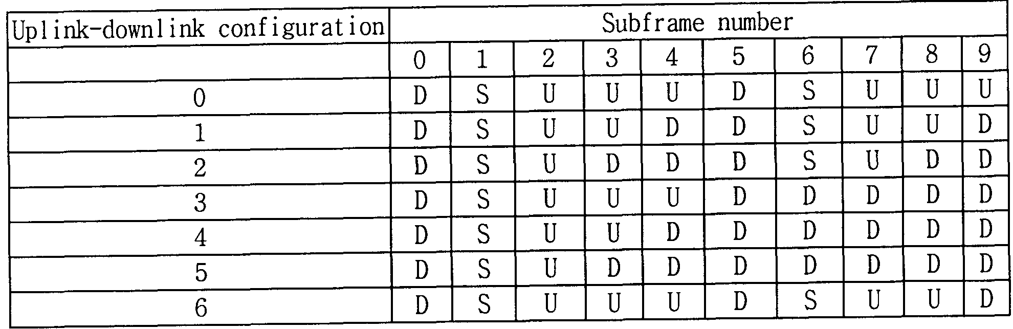


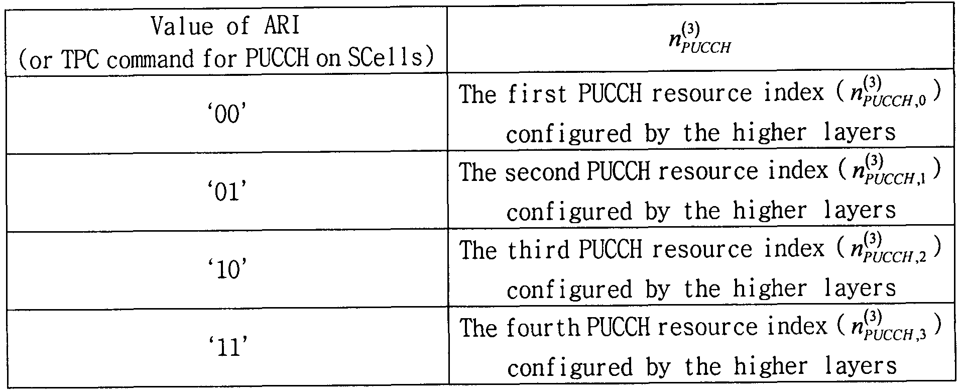


Claims
Priority Applications (7)
| Application Number | Priority Date | Filing Date | Title |
|---|---|---|---|
| EP19184470.3A EP3570474B1 (en) | 2010-11-11 | 2011-11-11 | Uplink control information transmitting/receiving method and device in a wireless communication system |
| KR1020137012635A KR101899820B1 (en) | 2010-11-11 | 2011-11-11 | Uplink control information transmitting/receiving method and device in a wireless communication system |
| US13/884,905 US9344999B2 (en) | 2010-11-11 | 2011-11-11 | Uplink control information transmitting/receiving method and device in a wireless communication system |
| JP2013538658A JP5946838B2 (en) | 2010-11-11 | 2011-11-11 | Method and apparatus for transmitting / receiving uplink control information in wireless communication system |
| EP11839830.4A EP2639984B1 (en) | 2010-11-11 | 2011-11-11 | Uplink control information transmitting/receiving method and device in a wireless communication system |
| CN201180063482.XA CN103283171B (en) | 2010-11-11 | 2011-11-11 | Uplink control information transmitting/receiving method and apparatus in wireless communication system |
| US15/099,414 US10057037B2 (en) | 2010-11-11 | 2016-04-14 | Uplink control information transmitting/receiving method and device in a wireless communication system |
Applications Claiming Priority (4)
| Application Number | Priority Date | Filing Date | Title |
|---|---|---|---|
| US41240510P | 2010-11-11 | 2010-11-11 | |
| US61/412,405 | 2010-11-11 | ||
| US201161483763P | 2011-05-09 | 2011-05-09 | |
| US61/483,763 | 2011-05-09 |
Related Child Applications (2)
| Application Number | Title | Priority Date | Filing Date |
|---|---|---|---|
| US13/884,905 A-371-Of-International US9344999B2 (en) | 2010-11-11 | 2011-11-11 | Uplink control information transmitting/receiving method and device in a wireless communication system |
| US15/099,414 Continuation US10057037B2 (en) | 2010-11-11 | 2016-04-14 | Uplink control information transmitting/receiving method and device in a wireless communication system |
Publications (2)
| Publication Number | Publication Date |
|---|---|
| WO2012064153A2 true WO2012064153A2 (en) | 2012-05-18 |
| WO2012064153A3 WO2012064153A3 (en) | 2012-07-19 |
Family
ID=46051455
Family Applications (3)
| Application Number | Title | Priority Date | Filing Date |
|---|---|---|---|
| PCT/KR2011/008632 WO2012064153A2 (en) | 2010-11-11 | 2011-11-11 | Uplink control information transmitting/receiving method and device in a wireless communication system |
| PCT/KR2011/008627 WO2012064151A2 (en) | 2010-11-11 | 2011-11-11 | Uplink control information transmitting/receiving method and device in a wireless communication system |
| PCT/KR2011/008633 WO2012064154A2 (en) | 2010-11-11 | 2011-11-11 | Uplink control information transmitting/receiving method and device in a wireless communication system |
Family Applications After (2)
| Application Number | Title | Priority Date | Filing Date |
|---|---|---|---|
| PCT/KR2011/008627 WO2012064151A2 (en) | 2010-11-11 | 2011-11-11 | Uplink control information transmitting/receiving method and device in a wireless communication system |
| PCT/KR2011/008633 WO2012064154A2 (en) | 2010-11-11 | 2011-11-11 | Uplink control information transmitting/receiving method and device in a wireless communication system |
Country Status (6)
| Country | Link |
|---|---|
| US (6) | US9369994B2 (en) |
| EP (4) | EP2639984B1 (en) |
| JP (7) | JP5873503B2 (en) |
| KR (3) | KR101899820B1 (en) |
| CN (3) | CN103283172B (en) |
| WO (3) | WO2012064153A2 (en) |
Cited By (2)
| Publication number | Priority date | Publication date | Assignee | Title |
|---|---|---|---|---|
| JP2014045493A (en) * | 2011-01-05 | 2014-03-13 | Panasonic Corp | Base station device and communication method |
| CN111052653A (en) * | 2017-08-04 | 2020-04-21 | 韦勒斯标准与技术协会公司 | Method, apparatus and system for transmitting or receiving data channel and control channel in wireless communication system |
Families Citing this family (132)
| Publication number | Priority date | Publication date | Assignee | Title |
|---|---|---|---|---|
| ES2905351T3 (en) * | 2009-03-17 | 2022-04-08 | Nokia Solutions & Networks Oy | Configuring Periodic Feedback Information Transmission on a Physical Uplink Shared Channel (PUSCH) |
| US20110116454A1 (en) * | 2009-05-04 | 2011-05-19 | Qualcomm Incorporated | Semi-persistent scheduling for multi-carrier wireless communication |
| WO2011122874A2 (en) * | 2010-03-31 | 2011-10-06 | Samsung Electronics Co., Ltd. | Indexing resources for transmission of acknowledgement signals in multi-cell tdd communication systems |
| JP5443317B2 (en) * | 2010-04-30 | 2014-03-19 | 株式会社Nttドコモ | Mobile terminal device and wireless communication method |
| JP5964314B2 (en) | 2010-11-02 | 2016-08-03 | エルジー エレクトロニクス インコーポレイティド | Method and apparatus for transmitting / receiving uplink control information in wireless communication system |
| CN105978660B (en) * | 2010-11-11 | 2019-06-25 | Lg电子株式会社 | Uplink control information transmitting/the method for reseptance and device of wireless communication system |
| CN103283172B (en) | 2010-11-11 | 2015-12-16 | Lg电子株式会社 | Uplink control information transmitting/receiving method and apparatus in wireless communication system |
| CN103503342B (en) * | 2011-03-04 | 2016-05-04 | Lg电子株式会社 | Thering is the method and apparatus that back haul link subframe is set in the wireless communication system of having applied carrier aggregation technology |
| EP2688239B1 (en) * | 2011-03-13 | 2018-11-28 | LG Electronics Inc. | Method for transmitting/receiving signal and device therefor |
| US9432982B2 (en) * | 2011-04-27 | 2016-08-30 | Lg Electronics Inc. | Method and apparatus for transmitting control information in wireless communication system |
| CN102202415B (en) * | 2011-05-18 | 2019-01-22 | 中兴通讯股份有限公司 | A kind of transmission method and system of Physical Random Access Channel |
| WO2013006379A1 (en) | 2011-07-01 | 2013-01-10 | Dinan Esmael Hejazi | Synchronization signal and control messages in multicarrier ofdm |
| US8582527B2 (en) | 2011-07-01 | 2013-11-12 | Ofinno Technologies, Llc | Hybrid automatic repeat request in multicarrier systems |
| US8369280B2 (en) | 2011-07-01 | 2013-02-05 | Ofinno Techologies, LLC | Control channels in multicarrier OFDM transmission |
| WO2013043023A2 (en) * | 2011-09-23 | 2013-03-28 | 엘지전자 주식회사 | Method for transmitting control information and apparatus for same |
| EP3038278B1 (en) | 2011-09-23 | 2017-07-26 | LG Electronics, Inc. | Method for transmitting control information and apparatus thereof |
| US8427976B1 (en) | 2011-12-04 | 2013-04-23 | Ofinno Technology, LLC | Carrier information exchange between base stations |
| KR20130069284A (en) * | 2011-12-16 | 2013-06-26 | 주식회사 팬택 | Transmission/reception point, timing configuration method thereof, user equipment, and pdsch a/n transmitting method thereof |
| US9838194B2 (en) | 2011-12-16 | 2017-12-05 | Goldpeak Innovations Inc | User equipment, PDSCH A/N transmitting method thereof, transmission/reception point, and PDSCH A/N receiving method thereof |
| JP5873708B2 (en) * | 2011-12-19 | 2016-03-01 | シャープ株式会社 | Mobile station apparatus, method and integrated circuit |
| EP3432666B1 (en) | 2011-12-22 | 2021-06-16 | Interdigital Patent Holdings, Inc. | Control signaling in lte carrier aggregation |
| CN103188062B (en) * | 2011-12-31 | 2018-08-17 | 中兴通讯股份有限公司 | Hybrid automatic repeat-request response message sending method and device |
| CN103209483B (en) * | 2012-01-12 | 2015-09-09 | 华为技术有限公司 | The method of transmitting uplink control information, subscriber equipment and base station |
| JP6167166B2 (en) | 2012-03-23 | 2017-07-26 | 聯發科技股▲ふん▼有限公司Mediatek Inc. | A method for allocating scheduling request resources in a mobile communication network |
| US9497756B2 (en) | 2012-03-25 | 2016-11-15 | Comcast Cable Communications, Llc | Base station radio resource management |
| EP3567762B1 (en) * | 2012-04-05 | 2020-12-09 | LG Electronics Inc. | Method and apparatus for aggregating carriers in wireless communication systems |
| US9949265B2 (en) | 2012-05-04 | 2018-04-17 | Comcast Cable Communications, Llc | Control channel in a wireless communication system |
| US8953635B2 (en) * | 2012-05-17 | 2015-02-10 | Sharp Kabushiki Kaisha | Devices for sending and receiving feedback information |
| CN102769509B (en) * | 2012-06-07 | 2015-10-21 | 华为技术有限公司 | A kind of sending method of physical layer signal, Apparatus and system |
| US8958331B2 (en) | 2012-07-02 | 2015-02-17 | Intel Corporation | HARQ-ACK handling for unintended downlink sub-frames |
| WO2014009483A1 (en) * | 2012-07-11 | 2014-01-16 | Nokia Siemens Networks Oy | Uplink control channel resource allocation for semi-persistent scheduling of user equipment |
| WO2014026381A1 (en) * | 2012-08-17 | 2014-02-20 | 华为技术有限公司 | Method and device for transmitting uplink control information |
| CN104641577B (en) * | 2012-09-19 | 2018-03-02 | Lg电子株式会社 | The method and apparatus for sending uplink control information |
| US8923880B2 (en) | 2012-09-28 | 2014-12-30 | Intel Corporation | Selective joinder of user equipment with wireless cell |
| US9014131B2 (en) * | 2012-10-31 | 2015-04-21 | Lg Electronics Inc. | Method for transmitting and receiving control information and apparatus for the same |
| JP6180732B2 (en) * | 2012-12-17 | 2017-08-16 | 株式会社Nttドコモ | User terminal, radio base station, and radio communication method |
| US9397796B2 (en) | 2013-03-13 | 2016-07-19 | Samsung Electronics Co., Ltd. | Computing and transmitting channel state information in adaptively configured TDD communication systems |
| KR20150029998A (en) | 2013-09-11 | 2015-03-19 | 현대자동차주식회사 | Method and apparatus for controlling of gear actuator |
| WO2015043873A1 (en) * | 2013-09-27 | 2015-04-02 | Nokia Solutions And Networks Oy | HARQ-ACK RESOURCE ALLOCATION AND USE FOR eIMTA |
| RU2663730C2 (en) * | 2013-11-25 | 2018-08-09 | Сони Корпорейшн | Communication control device, communication control method and terminal device |
| KR20150090727A (en) * | 2014-01-29 | 2015-08-06 | 삼성전자주식회사 | Apparatus and method for transmitting control channel in a carrier aggregation system |
| US9577814B2 (en) * | 2014-02-07 | 2017-02-21 | Samsung Electronics Co., Ltd. | Method and apparatus for allocating resources in carrier aggregation system |
| US9973362B2 (en) * | 2014-03-07 | 2018-05-15 | Huawei Technologies Co., Ltd. | Common broadcast channel low PAPR signaling in massive MIMO systems |
| JP6321201B2 (en) * | 2014-03-12 | 2018-05-09 | エルジー エレクトロニクス インコーポレイティド | Method and apparatus for transmitting uplink control channel in wireless communication system supporting changing usage of radio resource |
| US9408158B2 (en) | 2014-03-14 | 2016-08-02 | Sharp Laboratories Of America, Inc. | Systems and methods for feedback reporting |
| WO2016039682A1 (en) * | 2014-09-10 | 2016-03-17 | Telefonaktiebolaget L M Ericsson (Publ) | Radio access node, communication terminal and methods performed therein |
| US10064181B2 (en) * | 2014-10-03 | 2018-08-28 | Intel IP Corporation | Sub-band allocation techniques for reduced-bandwidth machine-type communication (MTC) devices |
| US10333679B2 (en) * | 2014-12-31 | 2019-06-25 | Lg Electronics Inc. | Method for transmitting ACK/NACK in wireless communication system and device using same |
| US10523397B2 (en) | 2015-01-20 | 2019-12-31 | Lg Electronics Inc. | Method for transmitting uplink control information and apparatus therefor |
| WO2016121433A1 (en) * | 2015-01-28 | 2016-08-04 | シャープ株式会社 | Terminal device, base station device, communication method, and integrated circuit |
| MY182077A (en) * | 2015-01-28 | 2021-01-18 | Sharp Kk | Terminal device, base station device, communication method, and integrated circuit |
| WO2016123372A1 (en) * | 2015-01-28 | 2016-08-04 | Interdigital Patent Holdings, Inc. | Uplink feedback methods for operating with a large number of carriers |
| US20180020430A1 (en) * | 2015-01-28 | 2018-01-18 | Sharp Kabushiki Kaisha | Terminal device, base station device, communication method, and integrated circuit |
| CN106160957B (en) * | 2015-01-29 | 2021-07-23 | 北京三星通信技术研究有限公司 | HARQ-ACK information feedback method and device |
| EP4156582A1 (en) * | 2015-01-29 | 2023-03-29 | Samsung Electronics Co., Ltd. | Harq-ack information feedback method and apparatus |
| WO2016119207A1 (en) * | 2015-01-30 | 2016-08-04 | Telefonaktiebolaget Lm Ericsson (Publ) | Harq/csi ack feedback method over unlicensed carriers |
| US9820298B2 (en) | 2015-03-09 | 2017-11-14 | Ofinno Technologies, Llc | Scheduling request in a wireless device and wireless network |
| US10182406B2 (en) | 2015-03-09 | 2019-01-15 | Comcast Cable Communications, Llc | Power headroom report for a wireless device and a base station |
| US10327236B2 (en) | 2015-03-09 | 2019-06-18 | Comcast Cable Communications, Llc | Secondary cell in a wireless device and wireless network |
| US9860029B2 (en) | 2015-03-09 | 2018-01-02 | Ofinno Technologies, Llc | Modification of secondary cells in carrier aggregation |
| US10700845B2 (en) | 2015-03-09 | 2020-06-30 | Comcast Cable Communications, Llc | Secondary cell deactivation in a wireless device and a base station |
| US9820264B2 (en) | 2015-03-09 | 2017-11-14 | Ofinno Technologies, Llc | Data and multicast signals in a wireless device and wireless network |
| MX2017012476A (en) * | 2015-03-30 | 2018-04-24 | Huawei Tech Co Ltd | Method, user equipment and base station for sending control information. |
| US9877334B2 (en) | 2015-04-05 | 2018-01-23 | Ofinno Technologies, Llc | Cell configuration in a wireless device and wireless network |
| US11641255B2 (en) | 2015-04-05 | 2023-05-02 | Comcast Cable Communications, Llc | Uplink control information transmission in a wireless network |
| JP6501903B2 (en) | 2015-04-08 | 2019-04-17 | ホアウェイ・テクノロジーズ・カンパニー・リミテッド | Network node user device and method thereof |
| WO2016161602A1 (en) * | 2015-04-09 | 2016-10-13 | Telefonaktiebolaget Lm Ericsson (Publ) | Pucch resource allocation and fallback operation |
| US9894681B2 (en) | 2015-06-12 | 2018-02-13 | Ofinno Technologies, Llc | Uplink scheduling in a wireless device and wireless network |
| US10200177B2 (en) | 2015-06-12 | 2019-02-05 | Comcast Cable Communications, Llc | Scheduling request on a secondary cell of a wireless device |
| US9948487B2 (en) | 2015-06-15 | 2018-04-17 | Ofinno Technologies, Llc | Uplink resource allocation in a wireless network |
| WO2016208927A1 (en) * | 2015-06-21 | 2016-12-29 | 엘지전자 주식회사 | Method and device for transmitting uplink in unlicensed band |
| CN113676307A (en) * | 2015-07-07 | 2021-11-19 | 索尼公司 | Communication apparatus and communication method |
| US10433328B2 (en) * | 2015-07-20 | 2019-10-01 | Lg Electronics Inc. | Method for receiving a signal in wireless communication system and a device therefor |
| KR102412484B1 (en) * | 2015-08-06 | 2022-06-24 | 씨스코 시스템즈, 인코포레이티드 | Apparatus and method for dynamic resource allocation for uplink control channel |
| JP6725516B2 (en) * | 2015-08-07 | 2020-07-22 | シャープ株式会社 | Terminal device and communication method |
| CN107925542A (en) * | 2015-08-12 | 2018-04-17 | Lg 电子株式会社 | Send and receive the method and its device of wireless signal |
| EP3337229A1 (en) * | 2015-08-13 | 2018-06-20 | NTT DoCoMo, Inc. | Wireless base station, user terminal, and wireless communication method |
| WO2017026402A1 (en) * | 2015-08-13 | 2017-02-16 | 株式会社Nttドコモ | User terminal, wireless base station, and wireless communication method |
| CN107925445B (en) | 2015-08-14 | 2020-08-07 | 华为技术有限公司 | Feedback information sending method, user equipment and base station |
| WO2017033780A1 (en) * | 2015-08-21 | 2017-03-02 | 株式会社Nttドコモ | User terminal, wireless base station, and wireless communication method |
| WO2017048215A1 (en) | 2015-09-17 | 2017-03-23 | Intel IP Corporation | Transmission of uplink control information in wireless systems |
| RU2690767C1 (en) | 2015-09-22 | 2019-06-05 | Хуавей Текнолоджиз Ко., Лтд. | Method and device for transmitting uplink control information during carrier aggregation |
| CN107294665A (en) * | 2016-04-01 | 2017-10-24 | 北京三星通信技术研究有限公司 | The feedback method and equipment of HARQ-ACK information |
| US10735146B2 (en) * | 2015-09-25 | 2020-08-04 | Samsung Electronics Co., Ltd. | Method and device for feeding back and receiving HARQ-ACK information |
| CN108141257B (en) * | 2015-10-05 | 2021-06-29 | 瑞典爱立信有限公司 | Method and apparatus for considering effective downlink channel generated from uplink reference signal beamforming |
| EP3364704B1 (en) * | 2015-11-03 | 2021-05-26 | Samsung Electronics Co., Ltd. | Method and device for transmitting or receiving control information in wireless communication system |
| KR102511925B1 (en) | 2015-11-06 | 2023-03-20 | 주식회사 아이티엘 | Apparatus and method for performing hybrid automatic repeat request operation in wireless communication system supporting carrier aggregation |
| US10448285B2 (en) * | 2015-12-22 | 2019-10-15 | Huawei Technologies Co., Ltd. | Mobility handling in ultra dense networks |
| CN107027181B (en) * | 2016-02-02 | 2020-02-04 | 电信科学技术研究院 | Method and device for transmitting uplink control information |
| US10903939B2 (en) | 2016-02-03 | 2021-01-26 | Sony Corporation | Terminal device, base station device, and communication method for setting TTI channel |
| CN108702739B (en) * | 2016-02-04 | 2022-12-09 | 联想创新有限公司(香港) | Transmission acknowledgement |
| JP6323473B2 (en) | 2016-02-25 | 2018-05-16 | トヨタ自動車株式会社 | Travel control device |
| US11844073B2 (en) * | 2016-02-26 | 2023-12-12 | Apple Inc. | Physical uplink control channel procedures |
| TW201743635A (en) * | 2016-03-30 | 2017-12-16 | 內數位專利控股公司 | Reducing latency in physical channels in an LTE network |
| KR20180131547A (en) * | 2016-04-01 | 2018-12-10 | 레노보 이노베이션스 리미티드 (홍콩) | Determining Carrier for Devices |
| US10790942B2 (en) | 2016-04-01 | 2020-09-29 | Samsung Electronics Co., Ltd | Method and apparatus for feeding back HARQ-ACK information |
| CN108781205B (en) * | 2016-04-06 | 2020-09-04 | 华为技术有限公司 | Information processing method and device |
| DE112016007007T5 (en) | 2016-06-22 | 2019-03-07 | Intel Corporation | COMMUNICATION DEVICE AND METHOD FOR FULL DUPLEX DISPOSITION |
| US10397944B2 (en) * | 2016-07-28 | 2019-08-27 | Qualcomm Incorporated | Apparatus and method for estimating downlink channel conditions at cell-edge |
| US10440706B2 (en) * | 2016-08-08 | 2019-10-08 | Sharp Kabushiki Kaisha | Systems and methods for PUCCH resource allocation and HARQ-ACK reporting with processing time reduction |
| US10404340B2 (en) | 2016-10-11 | 2019-09-03 | Qualcomm Incorporated | Dynamic adjustment of transmission properties with continuous precoding |
| KR102381306B1 (en) * | 2016-11-03 | 2022-03-31 | 프라운호퍼 게젤샤프트 쭈르 푀르데룽 데어 안겐반텐 포르슝 에. 베. | User equipment, base station, wireless communication network, data signal and method for providing continuous SPS after enhanced SPS control and handover |
| US9838173B1 (en) * | 2016-12-05 | 2017-12-05 | Telefonaktiebolaget Lm Ericsson (Publ) | Method and apparatus for transmission in a wireless communication network |
| CN108282881B (en) * | 2017-01-06 | 2020-12-15 | 华为技术有限公司 | Resource allocation method and device |
| EP3468081A4 (en) | 2017-02-05 | 2020-02-19 | LG Electronics Inc. -1- | Method for terminal transmitting uplink control information in wireless communication system and apparatus supporting same |
| US10411864B2 (en) * | 2017-02-06 | 2019-09-10 | Qualcomm Incorporated | Resource allocation for physical uplink control channel (PUCCH) |
| US10028210B1 (en) | 2017-03-23 | 2018-07-17 | At&T Intellectual Property I, L.P. | Encoding and decoding data for group common control channels |
| US20180315132A1 (en) * | 2017-04-28 | 2018-11-01 | Linkedin Corporation | Machine-language-based model for identifying peers on an online social network |
| CN114666016A (en) * | 2017-05-05 | 2022-06-24 | 瑞典爱立信有限公司 | Method, wireless device, network node, and medium for transmitting/receiving control information |
| CN114915385A (en) * | 2017-06-15 | 2022-08-16 | 日本电气株式会社 | Method and apparatus for cross-digital basic configuration scheduling |
| US10278184B2 (en) | 2017-08-10 | 2019-04-30 | At&T Intellectual Property I, L.P. | Radio resource management framework for 5G or other next generation network |
| WO2019047172A1 (en) | 2017-09-08 | 2019-03-14 | Zte Corporation | Uplink control channel resource allocation methods and devices |
| CN109803393B (en) * | 2017-11-17 | 2024-03-15 | 中兴通讯股份有限公司 | Information sending method and device |
| CN110035541B (en) * | 2018-01-11 | 2021-05-28 | 展讯通信(上海)有限公司 | Method and device for sending and processing scheduling request, storage medium, terminal and base station |
| US11172430B2 (en) * | 2018-01-12 | 2021-11-09 | Qualcomm Incorporated | Uplink control channel resource allocation |
| KR102069072B1 (en) * | 2018-02-14 | 2020-01-22 | 엘지전자 주식회사 | Method and apparatus for transmitting and receiving wireless signal in wireless communication system |
| EP3651534B1 (en) * | 2018-02-28 | 2021-07-28 | LG Electronics Inc. | Method for adjusting contention window size in wireless communication system and apparatus using method |
| US10779289B2 (en) | 2018-02-28 | 2020-09-15 | Lg Electronics Inc. | Method for adjusting contention window size in wireless communication system and apparatus using same |
| US11330569B2 (en) | 2018-04-06 | 2022-05-10 | Apple Inc. | Multiplexing of multiple uplink control information types on an uplink physical control channel in new radio |
| EP3776960A1 (en) * | 2018-04-06 | 2021-02-17 | Telefonaktiebolaget LM Ericsson (publ) | Power control for feedback signaling |
| SG11202101185QA (en) | 2018-08-07 | 2021-03-30 | Idac Holdings Inc | Methods and apparatus for harq enhancement |
| US20200107319A1 (en) * | 2018-09-28 | 2020-04-02 | Lenovo (Singapore) Pte. Ltd. | Method and apparatus for generating a csi report |
| US20200245334A1 (en) * | 2019-01-25 | 2020-07-30 | Qualcomm Incorporated | Preconfigured uplink resource techniques in wireless communications |
| US11818718B2 (en) | 2019-10-03 | 2023-11-14 | Qualcomm Incorporated | Physical uplink control channel format for single uplink operation in dual connectivity mode with time division duplexing primary cell |
| US20220394699A1 (en) * | 2019-10-31 | 2022-12-08 | Lg Electronics Inc. | Method and device for transmitting sidelink control channel in nr v2x |
| CN115399018A (en) * | 2020-04-08 | 2022-11-25 | 苹果公司 | Uplink control information reporting |
| US11523301B2 (en) * | 2020-04-20 | 2022-12-06 | Qualcomm Incorporated | Physical uplink control channel with buffer status report |
| US11758513B2 (en) | 2020-04-20 | 2023-09-12 | Qualcomm Incorporated | Physical uplink control channel with uplink message short data field |
| US11705949B2 (en) * | 2020-04-24 | 2023-07-18 | Qualcomm Incorporated | Techniques for channel state information report transmission triggered by negative acknowledgment (NACK) |
| US11877173B2 (en) * | 2020-05-20 | 2024-01-16 | Qualcomm Incorporated | Optimization of channel quality indicator (CQI) feedback for multiple component carriers |
| US20210391953A1 (en) * | 2020-06-12 | 2021-12-16 | Qualcomm Incorporated | Hybrid automatic repeat request feedback with multiple uplink channels |
| US20210399833A1 (en) * | 2020-06-19 | 2021-12-23 | Qualcomm Incorporated | Group feedback for multicast communications |
Family Cites Families (26)
| Publication number | Priority date | Publication date | Assignee | Title |
|---|---|---|---|---|
| US8036166B2 (en) | 2007-06-18 | 2011-10-11 | Nokia Corporation | Signaling of implicit ACK/NACK resources |
| KR20090015778A (en) | 2007-08-08 | 2009-02-12 | 엘지전자 주식회사 | Method for transmitting scheduling request signal |
| JP4574659B2 (en) | 2007-10-01 | 2010-11-04 | 株式会社エヌ・ティ・ティ・ドコモ | Mobile station apparatus, uplink transmission method, and communication system |
| KR100905385B1 (en) * | 2008-03-16 | 2009-06-30 | 엘지전자 주식회사 | Method for effective transmission of a control signal in a wireless communication system |
| CN102017462B (en) | 2008-04-21 | 2014-06-18 | Lg电子株式会社 | Method of transmitting control signal in wireless communication system |
| CN101616492B (en) | 2008-06-26 | 2012-04-04 | 中兴通讯股份有限公司 | Feedback method of ascending response message |
| US20110194514A1 (en) | 2008-07-30 | 2011-08-11 | Moon Il Lee | Method and apparatus of receiving data in wireless communication system |
| CN101651890A (en) | 2008-08-11 | 2010-02-17 | 夏普株式会社 | Method for feeding back uplink control signaling, base station, user equipment and communication system |
| KR101441147B1 (en) | 2008-08-12 | 2014-09-18 | 엘지전자 주식회사 | Method of transmitting sr in wireless communication system |
| CN101383683B (en) | 2008-09-22 | 2014-04-09 | 中兴通讯股份有限公司 | Feedback information sending method and device |
| AU2009307781B2 (en) | 2008-10-20 | 2014-04-10 | Interdigital Patent Holdings, Inc | Carrier aggregation |
| CN101431774B (en) * | 2008-11-28 | 2010-09-29 | 华为技术有限公司 | Resource allocation method and apparatus for physical uplink control channel, and base station |
| CN103825693B (en) | 2008-12-02 | 2017-08-04 | 三星电子株式会社 | The user equipment and its method of search dispatching distribution |
| US20100177694A1 (en) * | 2009-01-09 | 2010-07-15 | Industrial Technology Research Institute | Apparatus and method for transmitting uplink control information |
| US8295253B2 (en) * | 2009-02-05 | 2012-10-23 | Qualcomm Incorporated | Efficient ACK transmission for uplink semi-persistent scheduling release in LTE |
| CN101801025B (en) | 2009-02-06 | 2013-10-02 | 电信科学技术研究院 | Method and equipment for confirming scheduling resource release |
| KR101590010B1 (en) * | 2009-02-27 | 2016-01-29 | 엘지전자 주식회사 | Method of transmitting channel quality information of downlink multi carriers in a wireless communication system |
| KR101715938B1 (en) | 2009-03-03 | 2017-03-14 | 엘지전자 주식회사 | Method and apparatus for transmitting harq ack/nack signal in multiple antenna system |
| WO2010123304A2 (en) | 2009-04-24 | 2010-10-28 | Samsung Electronics Co., Ltd. | Multiplexing large payloads of control information from user equipments |
| WO2011019795A1 (en) * | 2009-08-13 | 2011-02-17 | Interdigital Patent Holdings, Inc. | Multiplexing uplink l1/l2 control and data |
| PL2484039T3 (en) * | 2009-10-01 | 2019-01-31 | Interdigital Patent Holdings, Inc. | Uplink control data transmission |
| CN101783718A (en) | 2010-02-10 | 2010-07-21 | 中兴通讯股份有限公司 | Multiplexing method of scheduling request messages and correct and wrong answer messages |
| CN101834658B (en) | 2010-05-05 | 2016-01-20 | 中兴通讯股份有限公司 | A kind of uplink control signaling sending method and equipment |
| BR112012032414B1 (en) * | 2010-06-18 | 2021-04-20 | Nokia Solutions And Networks Oy | improved uplink control physical channel format resource allocation for duplex time division mode |
| CN105978660B (en) | 2010-11-11 | 2019-06-25 | Lg电子株式会社 | Uplink control information transmitting/the method for reseptance and device of wireless communication system |
| CN103283172B (en) | 2010-11-11 | 2015-12-16 | Lg电子株式会社 | Uplink control information transmitting/receiving method and apparatus in wireless communication system |
-
2011
- 2011-11-11 CN CN201180063616.8A patent/CN103283172B/en active Active
- 2011-11-11 EP EP11839830.4A patent/EP2639984B1/en active Active
- 2011-11-11 JP JP2013538656A patent/JP5873503B2/en active Active
- 2011-11-11 KR KR1020137012635A patent/KR101899820B1/en active IP Right Grant
- 2011-11-11 KR KR1020137012637A patent/KR101901933B1/en active IP Right Grant
- 2011-11-11 KR KR1020137012636A patent/KR101842202B1/en active IP Right Grant
- 2011-11-11 JP JP2013538659A patent/JP5834087B2/en active Active
- 2011-11-11 EP EP11840282.5A patent/EP2639986B1/en active Active
- 2011-11-11 WO PCT/KR2011/008632 patent/WO2012064153A2/en active Application Filing
- 2011-11-11 US US13/884,818 patent/US9369994B2/en active Active
- 2011-11-11 WO PCT/KR2011/008627 patent/WO2012064151A2/en active Application Filing
- 2011-11-11 CN CN201180063620.4A patent/CN103299571B/en active Active
- 2011-11-11 US US13/884,905 patent/US9344999B2/en active Active
- 2011-11-11 CN CN201180063482.XA patent/CN103283171B/en active Active
- 2011-11-11 US US13/884,922 patent/US9510326B2/en active Active
- 2011-11-11 EP EP11839846.0A patent/EP2639985B1/en active Active
- 2011-11-11 WO PCT/KR2011/008633 patent/WO2012064154A2/en active Application Filing
- 2011-11-11 JP JP2013538658A patent/JP5946838B2/en active Active
- 2011-11-11 EP EP19184470.3A patent/EP3570474B1/en active Active
-
2015
- 2015-10-30 JP JP2015213683A patent/JP6001752B2/en active Active
-
2016
- 2016-01-15 JP JP2016005745A patent/JP6162266B2/en active Active
- 2016-04-14 US US15/099,414 patent/US10057037B2/en active Active
- 2016-05-05 US US15/147,708 patent/US10069612B2/en active Active
- 2016-06-01 JP JP2016110044A patent/JP6322225B2/en active Active
- 2016-09-01 JP JP2016170856A patent/JP6220431B2/en active Active
- 2016-11-01 US US15/340,741 patent/US10142080B2/en active Active
Non-Patent Citations (2)
| Title |
|---|
| None |
| See also references of EP2639984A4 |
Cited By (14)
| Publication number | Priority date | Publication date | Assignee | Title |
|---|---|---|---|---|
| US9820267B2 (en) | 2011-01-05 | 2017-11-14 | Sun Patent Trust | Terminal device, base station device, transmitting method and receiving method |
| JP2014045493A (en) * | 2011-01-05 | 2014-03-13 | Panasonic Corp | Base station device and communication method |
| US9077533B2 (en) | 2011-01-05 | 2015-07-07 | Panasonic Intellectual Property Corporation Of America | Terminal device, base station device, transmitting method and receiving method |
| US9295054B2 (en) | 2011-01-05 | 2016-03-22 | Panasonic Intellectual Property Corporation Of America | Terminal device, base station device, transmitting method and receiving method |
| US9467987B2 (en) | 2011-01-05 | 2016-10-11 | Sun Patent Trust | Terminal device, base station device, transmitting method and receiving method |
| US9668249B2 (en) | 2011-01-05 | 2017-05-30 | Sun Patent Trust | Terminal device, base station device, transmitting method and receiving method |
| US8879497B2 (en) | 2011-01-05 | 2014-11-04 | Panasonic Intellectual Property Corporation Of America | Terminal device, base station device, transmitting method and receiving method |
| US10306607B2 (en) | 2011-01-05 | 2019-05-28 | Sun Patent Trust | Terminal device, base station device, transmitting method and receiving method |
| US11375485B2 (en) | 2011-01-05 | 2022-06-28 | Sun Patent Trust | Terminal device, base station device, transmitting method and receiving method |
| US10694510B2 (en) | 2011-01-05 | 2020-06-23 | Sun Patent Trust | Terminal device, base station device, transmitting method and receiving method |
| US11716735B2 (en) | 2011-01-05 | 2023-08-01 | Sun Patent Trust | Terminal device, base station device, transmitting method and receiving method |
| CN111052653B (en) * | 2017-08-04 | 2022-11-15 | 韦勒斯标准与技术协会公司 | Method, apparatus and system for transmitting or receiving data channel and control channel in wireless communication system |
| US11533131B2 (en) | 2017-08-04 | 2022-12-20 | Wilus Institute Of Standards And Technology Inc. | Method, apparatus, and system for transmitting or receiving data channel and control channel in wireless communication system |
| CN111052653A (en) * | 2017-08-04 | 2020-04-21 | 韦勒斯标准与技术协会公司 | Method, apparatus and system for transmitting or receiving data channel and control channel in wireless communication system |
Also Published As
Similar Documents
| Publication | Publication Date | Title |
|---|---|---|
| JP7138088B2 (en) | Method and apparatus for transmitting and receiving uplink control information in wireless communication system | |
| JP6220431B2 (en) | Method and apparatus for transmitting / receiving uplink control information in wireless communication system | |
| KR101191216B1 (en) | Method and user equipment for transmitting uplink control information, and method and base station for receiving uplink control information |
Legal Events
| Date | Code | Title | Description |
|---|---|---|---|
| WWE | Wipo information: entry into national phase |
Ref document number: 201180063482.X Country of ref document: CN |
|
| 121 | Ep: the epo has been informed by wipo that ep was designated in this application |
Ref document number: 11839830 Country of ref document: EP Kind code of ref document: A2 |
|
| ENP | Entry into the national phase |
Ref document number: 2013538658 Country of ref document: JP Kind code of ref document: A |
|
| WWE | Wipo information: entry into national phase |
Ref document number: 13884905 Country of ref document: US |
|
| NENP | Non-entry into the national phase |
Ref country code: DE |
|
| ENP | Entry into the national phase |
Ref document number: 20137012635 Country of ref document: KR Kind code of ref document: A |
|
| WWE | Wipo information: entry into national phase |
Ref document number: 2011839830 Country of ref document: EP |