KR101842202B1 - Uplink control information transmitting/receiving method and device in a wireless communication system - Google Patents
Uplink control information transmitting/receiving method and device in a wireless communication system Download PDFInfo
- Publication number
- KR101842202B1 KR101842202B1 KR1020137012636A KR20137012636A KR101842202B1 KR 101842202 B1 KR101842202 B1 KR 101842202B1 KR 1020137012636 A KR1020137012636 A KR 1020137012636A KR 20137012636 A KR20137012636 A KR 20137012636A KR 101842202 B1 KR101842202 B1 KR 101842202B1
- Authority
- KR
- South Korea
- Prior art keywords
- pdcch
- ack
- nack
- pdsch
- pcell
- Prior art date
Links
Images


Classifications
-
- H—ELECTRICITY
- H04—ELECTRIC COMMUNICATION TECHNIQUE
- H04L—TRANSMISSION OF DIGITAL INFORMATION, e.g. TELEGRAPHIC COMMUNICATION
- H04L1/00—Arrangements for detecting or preventing errors in the information received
- H04L1/12—Arrangements for detecting or preventing errors in the information received by using return channel
- H04L1/16—Arrangements for detecting or preventing errors in the information received by using return channel in which the return channel carries supervisory signals, e.g. repetition request signals
- H04L1/1607—Details of the supervisory signal
- H04L1/1671—Details of the supervisory signal the supervisory signal being transmitted together with control information
-
- H—ELECTRICITY
- H04—ELECTRIC COMMUNICATION TECHNIQUE
- H04L—TRANSMISSION OF DIGITAL INFORMATION, e.g. TELEGRAPHIC COMMUNICATION
- H04L5/00—Arrangements affording multiple use of the transmission path
- H04L5/003—Arrangements for allocating sub-channels of the transmission path
- H04L5/0053—Allocation of signaling, i.e. of overhead other than pilot signals
- H04L5/0055—Physical resource allocation for ACK/NACK
-
- H—ELECTRICITY
- H04—ELECTRIC COMMUNICATION TECHNIQUE
- H04L—TRANSMISSION OF DIGITAL INFORMATION, e.g. TELEGRAPHIC COMMUNICATION
- H04L1/00—Arrangements for detecting or preventing errors in the information received
- H04L1/0001—Systems modifying transmission characteristics according to link quality, e.g. power backoff
- H04L1/0023—Systems modifying transmission characteristics according to link quality, e.g. power backoff characterised by the signalling
- H04L1/0026—Transmission of channel quality indication
-
- H—ELECTRICITY
- H04—ELECTRIC COMMUNICATION TECHNIQUE
- H04L—TRANSMISSION OF DIGITAL INFORMATION, e.g. TELEGRAPHIC COMMUNICATION
- H04L1/00—Arrangements for detecting or preventing errors in the information received
- H04L1/12—Arrangements for detecting or preventing errors in the information received by using return channel
- H04L1/16—Arrangements for detecting or preventing errors in the information received by using return channel in which the return channel carries supervisory signals, e.g. repetition request signals
- H04L1/18—Automatic repetition systems, e.g. Van Duuren systems
- H04L1/1829—Arrangements specially adapted for the receiver end
- H04L1/1854—Scheduling and prioritising arrangements
-
- H—ELECTRICITY
- H04—ELECTRIC COMMUNICATION TECHNIQUE
- H04L—TRANSMISSION OF DIGITAL INFORMATION, e.g. TELEGRAPHIC COMMUNICATION
- H04L27/00—Modulated-carrier systems
- H04L27/26—Systems using multi-frequency codes
- H04L27/2601—Multicarrier modulation systems
- H04L27/2647—Arrangements specific to the receiver only
-
- H—ELECTRICITY
- H04—ELECTRIC COMMUNICATION TECHNIQUE
- H04L—TRANSMISSION OF DIGITAL INFORMATION, e.g. TELEGRAPHIC COMMUNICATION
- H04L5/00—Arrangements affording multiple use of the transmission path
- H04L5/14—Two-way operation using the same type of signal, i.e. duplex
-
- H—ELECTRICITY
- H04—ELECTRIC COMMUNICATION TECHNIQUE
- H04L—TRANSMISSION OF DIGITAL INFORMATION, e.g. TELEGRAPHIC COMMUNICATION
- H04L5/00—Arrangements affording multiple use of the transmission path
- H04L5/22—Arrangements affording multiple use of the transmission path using time-division multiplexing
-
- H—ELECTRICITY
- H04—ELECTRIC COMMUNICATION TECHNIQUE
- H04W—WIRELESS COMMUNICATION NETWORKS
- H04W72/00—Local resource management
- H04W72/04—Wireless resource allocation
-
- H—ELECTRICITY
- H04—ELECTRIC COMMUNICATION TECHNIQUE
- H04W—WIRELESS COMMUNICATION NETWORKS
- H04W72/00—Local resource management
- H04W72/04—Wireless resource allocation
- H04W72/044—Wireless resource allocation based on the type of the allocated resource
- H04W72/0446—Resources in time domain, e.g. slots or frames
-
- H—ELECTRICITY
- H04—ELECTRIC COMMUNICATION TECHNIQUE
- H04W—WIRELESS COMMUNICATION NETWORKS
- H04W72/00—Local resource management
- H04W72/20—Control channels or signalling for resource management
- H04W72/21—Control channels or signalling for resource management in the uplink direction of a wireless link, i.e. towards the network
-
- H—ELECTRICITY
- H04—ELECTRIC COMMUNICATION TECHNIQUE
- H04W—WIRELESS COMMUNICATION NETWORKS
- H04W72/00—Local resource management
- H04W72/20—Control channels or signalling for resource management
- H04W72/23—Control channels or signalling for resource management in the downlink direction of a wireless link, i.e. towards a terminal
-
- H—ELECTRICITY
- H04—ELECTRIC COMMUNICATION TECHNIQUE
- H04L—TRANSMISSION OF DIGITAL INFORMATION, e.g. TELEGRAPHIC COMMUNICATION
- H04L1/00—Arrangements for detecting or preventing errors in the information received
- H04L1/12—Arrangements for detecting or preventing errors in the information received by using return channel
- H04L1/16—Arrangements for detecting or preventing errors in the information received by using return channel in which the return channel carries supervisory signals, e.g. repetition request signals
- H04L1/18—Automatic repetition systems, e.g. Van Duuren systems
- H04L1/1812—Hybrid protocols; Hybrid automatic repeat request [HARQ]
-
- H—ELECTRICITY
- H04—ELECTRIC COMMUNICATION TECHNIQUE
- H04L—TRANSMISSION OF DIGITAL INFORMATION, e.g. TELEGRAPHIC COMMUNICATION
- H04L27/00—Modulated-carrier systems
- H04L27/26—Systems using multi-frequency codes
- H04L27/2601—Multicarrier modulation systems
- H04L27/2626—Arrangements specific to the transmitter only
- H04L27/2627—Modulators
- H04L27/2634—Inverse fast Fourier transform [IFFT] or inverse discrete Fourier transform [IDFT] modulators in combination with other circuits for modulation
- H04L27/2636—Inverse fast Fourier transform [IFFT] or inverse discrete Fourier transform [IDFT] modulators in combination with other circuits for modulation with FFT or DFT modulators, e.g. standard single-carrier frequency-division multiple access [SC-FDMA] transmitter or DFT spread orthogonal frequency division multiplexing [DFT-SOFDM]
-
- H—ELECTRICITY
- H04—ELECTRIC COMMUNICATION TECHNIQUE
- H04L—TRANSMISSION OF DIGITAL INFORMATION, e.g. TELEGRAPHIC COMMUNICATION
- H04L5/00—Arrangements affording multiple use of the transmission path
- H04L5/0001—Arrangements for dividing the transmission path
- H04L5/0003—Two-dimensional division
- H04L5/0005—Time-frequency
- H04L5/0007—Time-frequency the frequencies being orthogonal, e.g. OFDM(A), DMT
- H04L5/001—Time-frequency the frequencies being orthogonal, e.g. OFDM(A), DMT the frequencies being arranged in component carriers
-
- H—ELECTRICITY
- H04—ELECTRIC COMMUNICATION TECHNIQUE
- H04L—TRANSMISSION OF DIGITAL INFORMATION, e.g. TELEGRAPHIC COMMUNICATION
- H04L5/00—Arrangements affording multiple use of the transmission path
- H04L5/0001—Arrangements for dividing the transmission path
- H04L5/0014—Three-dimensional division
- H04L5/0016—Time-frequency-code
- H04L5/0017—Time-frequency-code in which a distinct code is applied, as a temporal sequence, to each frequency
-
- H—ELECTRICITY
- H04—ELECTRIC COMMUNICATION TECHNIQUE
- H04W—WIRELESS COMMUNICATION NETWORKS
- H04W72/00—Local resource management
- H04W72/12—Wireless traffic scheduling
- H04W72/1263—Mapping of traffic onto schedule, e.g. scheduled allocation or multiplexing of flows
- H04W72/1268—Mapping of traffic onto schedule, e.g. scheduled allocation or multiplexing of flows of uplink data flows
-
- H—ELECTRICITY
- H04—ELECTRIC COMMUNICATION TECHNIQUE
- H04W—WIRELESS COMMUNICATION NETWORKS
- H04W74/00—Wireless channel access, e.g. scheduled or random access
- H04W74/002—Transmission of channel access control information
- H04W74/004—Transmission of channel access control information in the uplink, i.e. towards network
Abstract
본 발명은 무선 통신 시스템에 대한 것으로, 보다 상세하게는 상향링크 제어정보를 송수신하는 방법 및 장치가 개시된다. 본 발명의 일 실시예에 따른 무선 통신 시스템에서 단말이 확인응답 정보를 전송하는 방법은, M(M≥1)개의 하향링크 서브프레임을 포함하는 하향링크 서브프레임 세트에서의 하향링크 전송에 대한 확인응답 정보가 전송될 하나의 상향링크 서브프레임에서 스케줄링 요청의 전송이 설정되어 있는지 결정하는 단계; 상기 확인응답 정보가 전송될 PUCCH(Physical Uplink Control CHannel) 포맷 및 자원을 결정하는 단계; 및 상기 PUCCH 포맷 및 자원을 이용해서 상기 확인응답 정보를 전송하는 단계를 포함할 수 있다. 상기 하나의 상향링크 서브프레임에서 상기 스케줄링 요청의 전송이 설정되어 있으면, 상기 하향링크 서브프레임 세트 내에서 SPS(Semi-Persistent Scheduling) 해제 PDCCH(Physical Downlink Control CHannel)가 존재하지 않고, 상기 확인응답 정보가 상기 하향링크 서브프레임 세트 내에서 PCell(Primary Cell) 상에서만 수신된 대응 PDCCH(Physical Downlink Control CHannel)가 없는 하나의 PDSCH(Physical Downlink Shared CHannel) 및 상기 하향링크 서브프레임 세트 내에서 PCell 상에서만 수신된 대응 PDCCH의 검출에 의해 지시되는 하나의 PDSCH에 대응하고 상기 PDCCH의 DAI(Downlink Assignment Index) 값이 1 인 경우에, 상기 확인응답 정보 및 상기 스케줄링 요청은 PUCCH 포맷 1b 를 이용하여 상기 하나의 상향링크 서브프레임에서 전송될 수 있다.The present invention relates to a wireless communication system, and more particularly, to a method and apparatus for transmitting / receiving uplink control information. A method for a UE to transmit acknowledgment information in a wireless communication system according to an exemplary embodiment of the present invention includes: checking for downlink transmission in a downlink subframe set including M (M? 1) Determining whether transmission of a scheduling request is set in one uplink subframe to which response information is to be transmitted; Determining a Physical Uplink Control CHannel (PUCCH) format and resources to which the acknowledgment information is to be transmitted; And transmitting the acknowledgment information using the PUCCH format and resources. If transmission of the scheduling request is set in the one uplink subframe, there is no PDSCH (Physical Downlink Control CHannel) released in the SPS (Semi-Persistent Scheduling) in the DL subframe set, (Physical Downlink Shared CHannel) that does not have a corresponding PDCCH (Physical Downlink Control CHannel) received only on a PC cell in the DL subframe set and a PDSCH Wherein the acknowledgment information and the scheduling request correspond to one PDSCH indicated by the detection of the corresponding PDCCH and the DAI (Downlink Assignment Index) value of the PDCCH is 1, Link sub-frame.
Description
이하의 설명은 무선 통신 시스템에 대한 것으로, 보다 상세하게는 상향링크 제어정보를 송수신하는 방법 및 장치에 대한 것이다.The following description relates to a wireless communication system, and more particularly, to a method and apparatus for transmitting and receiving uplink control information.
무선 통신 시스템이 음성이나 데이터 등과 같은 다양한 종류의 통신 서비스를 제공하기 위해 광범위하게 전개되고 있다. 일반적으로 무선 통신 시스템은 가용한 시스템 자원(대역폭, 전송 파워 등)을 공유하여 다중 사용자와의 통신을 지원할 수 있는 다중 접속(multiple access) 시스템이다. 다중 접속 시스템의 예들로는 CDMA(code division multiple access) 시스템, FDMA(frequency division multiple access) 시스템, TDMA(time division multiple access) 시스템, OFDMA(orthogonal frequency division multiple access) 시스템, SC-FDMA(single carrier frequency division multiple access) 시스템, MC-FDMA(multi carrier frequency division multiple access) 시스템 등이 있다.Background of the Invention [0002] Wireless communication systems are widely deployed to provide various types of communication services such as voice and data. Generally, a wireless communication system is a multiple access system capable of supporting communication with multiple users by sharing available system resources (bandwidth, transmission power, etc.). Examples of multiple access systems include a code division multiple access (CDMA) system, a frequency division multiple access (FDMA) system, a time division multiple access (TDMA) system, an orthogonal frequency division multiple access (OFDMA) system, a single carrier frequency division multiple access (MC-FDMA) system, and a multi-carrier frequency division multiple access (MC-FDMA) system.
본 발명의 목적은 무선 통신 시스템에서 제어 정보를 효율적으로 전송하는 방법 및 이를 위한 장치를 제공하는 데 있다. 본 발명의 다른 목적은 제어 정보를 효율적으로 전송하기 위한 채널 포맷, 신호 처리, 및 이를 위한 장치를 제공하는 데 있다. 본 발명의 또 다른 목적은 제어 정보를 전송하기 위한 자원을 효율적으로 할당하는 방법 및 이를 위한 장치를 제공하는 데 있다.It is an object of the present invention to provide a method and apparatus for efficiently transmitting control information in a wireless communication system. It is another object of the present invention to provide a channel format, signal processing, and apparatus for efficiently transmitting control information. It is still another object of the present invention to provide a method and apparatus for efficiently allocating resources for transmitting control information.
본 발명에서 이루고자 하는 기술적 과제들은 이상에서 언급한 기술적 과제들로 제한되지 않으며, 언급하지 않은 또 다른 기술적 과제들은 아래의 기재로부터 본 발명이 속하는 기술분야에서 통상의 지식을 가진 자에게 명확하게 이해될 수 있을 것이다.It is to be understood that both the foregoing general description and the following detailed description are exemplary and explanatory and are not intended to limit the invention to the precise forms disclosed. It will be possible.
상기의 기술적 과제를 해결하기 위하여 본 발명의 일 실시예에 따른 무선 통신 시스템에서 단말이 확인응답 정보를 전송하는 방법은, M(M≥1)개의 하향링크 서브프레임을 포함하는 하향링크 서브프레임 세트에서의 하향링크 전송에 대한 확인응답 정보가 전송될 하나의 상향링크 서브프레임에서 스케줄링 요청의 전송이 설정되어 있는지 결정하는 단계; 상기 확인응답 정보가 전송될 PUCCH(Physical Uplink Control CHannel) 포맷 및 자원을 결정하는 단계; 및 상기 PUCCH 포맷 및 자원을 이용해서 상기 확인응답 정보를 전송하는 단계를 포함할 수 있다. 상기 하나의 상향링크 서브프레임에서 상기 스케줄링 요청의 전송이 설정되어 있으면, 상기 하향링크 서브프레임 세트 내에서 SPS(Semi-Persistent Scheduling) 해제 PDCCH(Physical Downlink Control CHannel)가 존재하지 않고, 상기 확인응답 정보가 상기 하향링크 서브프레임 세트 내에서 PCell(Primary Cell) 상에서만 수신된 대응 PDCCH(Physical Downlink Control CHannel)가 없는 하나의 PDSCH(Physical Downlink Shared CHannel) 및 상기 하향링크 서브프레임 세트 내에서 PCell 상에서만 수신된 대응 PDCCH의 검출에 의해 지시되는 하나의 PDSCH에 대응하고 상기 PDCCH의 DAI(Downlink Assignment Index) 값이 1 인 경우에, 상기 확인응답 정보 및 상기 스케줄링 요청은 PUCCH 포맷 1b 를 이용하여 상기 하나의 상향링크 서브프레임에서 전송될 수 있다.According to an aspect of the present invention, there is provided a method for transmitting acknowledgment information in a wireless communication system, the method comprising: receiving a downlink subframe set including M (M? 1) Determining whether transmission of a scheduling request is set in one uplink subframe to which acknowledgment information for downlink transmission is to be transmitted; Determining a Physical Uplink Control CHannel (PUCCH) format and resources to which the acknowledgment information is to be transmitted; And transmitting the acknowledgment information using the PUCCH format and resources. If transmission of the scheduling request is set in the one uplink subframe, there is no PDSCH (Physical Downlink Control CHannel) released in the SPS (Semi-Persistent Scheduling) in the DL subframe set, (Physical Downlink Shared CHannel) that does not have a corresponding PDCCH (Physical Downlink Control CHannel) received only on a PC cell in the DL subframe set and a PDSCH Wherein the acknowledgment information and the scheduling request correspond to one PDSCH indicated by the detection of the corresponding PDCCH and the DAI (Downlink Assignment Index) value of the PDCCH is 1, Link sub-frame.
상기의 기술적 과제를 해결하기 위하여 본 발명의 다른 실시예에 따른 무선 통신 시스템에서 확인응답 정보를 전송하는 단말은, 기지국으로부터 하향링크 신호를 수신하는 수신 모듈; 상기 기지국으로 상향링크 신호를 전송하는 전송 모듈; 및 상기 수신 모듈 및 상기 전송 모듈을 포함하는 상기 단말을 제어하는 프로세서를 포함할 수 있다. 상기 프로세서는, M(M≥1)개의 하향링크 서브프레임을 포함하는 하향링크 서브프레임 세트에서의 하향링크 전송에 대한 확인응답 정보가 전송될 하나의 상향링크 서브프레임에서 스케줄링 요청의 전송이 설정되어 있는지 결정하고; 상기 확인응답 정보가 전송될 PUCCH(Physical Uplink Control CHannel) 포맷 및 자원을 결정하고; 상기 PUCCH 포맷 및 자원을 이용해서 상기 확인응답 정보를 상기 전송 모듈을 통하여 전송하도록 구성될 수 있다. 여기서, 상기 하나의 상향링크 서브프레임에서 상기 스케줄링 요청의 전송이 설정되어 있으면, 상기 하향링크 서브프레임 세트 내에서 SPS(Semi-Persistent Scheduling) 해제 PDCCH(Physical Downlink Control CHannel)가 존재하지 않고, 상기 확인응답 정보가 상기 하향링크 서브프레임 세트 내에서 PCell(Primary Cell) 상에서만 수신된 대응 PDCCH(Physical Downlink Control CHannel)가 없는 하나의 PDSCH(Physical Downlink Shared CHannel) 및 상기 하향링크 서브프레임 세트 내에서 PCell 상에서만 수신된 대응 PDCCH의 검출에 의해 지시되는 하나의 PDSCH에 대응하고 상기 PDCCH의 DAI(Downlink Assignment Index) 값이 1 인 경우에, 상기 확인응답 정보 및 상기 스케줄링 요청은 PUCCH 포맷 1b 를 이용하여 상기 하나의 상향링크 서브프레임에서 전송될 수 있다.According to another aspect of the present invention, there is provided a terminal for transmitting acknowledgment information in a wireless communication system, the terminal including: a receiving module for receiving a downlink signal from a base station; A transmission module for transmitting an uplink signal to the base station; And a processor for controlling the terminal including the receiving module and the transmitting module. The processor sets up transmission of a scheduling request in one uplink subframe in which acknowledgment information for downlink transmission in a downlink subframe set including M (M? 1) downlink subframes is to be transmitted Determine whether; Determine a PUCCH (Physical Uplink Control CHannel) format and resources to which the acknowledgment information is to be transmitted; And transmit the acknowledgment information through the transmission module using the PUCCH format and resources. If transmission of the scheduling request is set in the one uplink subframe, there is no PDSCH (Physical Downlink Control CHannel) released in the SPS (Semi-Persistent Scheduling) in the DL subframe set, Response information is transmitted on one PDSCH (Physical Downlink Shared CHannel) that does not have a corresponding PDCCH (Physical Downlink Control CHannel) received only on a PC cell in the DL subframe set and on a PCell in the downlink subframe set Only one PDSCH indicated by the detection of the corresponding PDCCH received and a Downlink Assignment Index (DAI) value of the PDCCH is one, the acknowledgment information and the scheduling request are transmitted to the one Lt; RTI ID = 0.0 > uplink < / RTI >
본 발명의 전술한 실시예들에 대하여 이하의 사항이 공통으로 적용될 수 있다.The following items can be commonly applied to the above-described embodiments of the present invention.
상기 하향링크 서브프레임 세트 내에서 대응 PDCCH의 검출에 의해 지시되는 PDSCH가 존재하지 않고, 상기 확인응답 정보가 상기 하향링크 서브프레임 세트 내에서 PCell 상에서만 수신된 대응 PDCCH가 없는 하나의 PDSCH 및 SPS 해제 PDCCH에 대응하고 상기 SPS 해제 PDCCH의 DAI가 1 인 경우에, 상기 확인응답 정보 및 상기 스케줄링 요청은 PUCCH 포맷 1b 를 이용하여 상기 하나의 상향링크 서브프레임에서 전송될 수 있다.One PDSCH and one SPS release in which there is no PDSCH indicated by the detection of a corresponding PDCCH in the downlink subframe set and the acknowledgment information is not present on the PCell in the downlink subframe set, PDCCH and the DAI of the SPS release PDCCH is 1, the acknowledgment information and the scheduling request can be transmitted in the one uplink subframe using the
긍정(positive) 스케줄링 요청의 경우에, 상기 스케줄링 요청을 위해 할당 받은 PUCCH 자원 상에서 긍정확인응답(ACK)의 개수를 나타내는 정보가 전송되고, 부정(negative) 스케줄링 요청의 경우에, 상기 확인응답 정보를 위해 할당 받은 PUCCH 자원 상에서 상기 확인응답 정보가 전송될 수 있다.In the case of a positive scheduling request, information indicating the number of ACKs is transmitted on the PUCCH resource allocated for the scheduling request, and in the case of a negative scheduling request, The acknowledgment information may be transmitted on the PUCCH resource allocated for the PUCCH resource.
상기 ACK의 개수를 나타내는 정보는 2 비트 크기를 가질 수 있다.The information indicating the number of ACKs may have a size of 2 bits.
상기 ACK의 개수를 나타내는 정보는 '0,0' , '0,1' , '1,0' , '1,1' 중 하나의 값을 가지고, 상기 ACK의 개수를 나타내는 정보의 값이 '0,1' , '1,0' , '1,1' 인 경우의 각각은, ACK의 개수에 대한 복수개의 경우에 매핑될 수 있다.Information indicating the number of ACKs has one of '0,0', '0,1', '1,0' and '1,1', and the value of the information indicating the number of ACKs is' 0 , 1 ',' 1,0 ', and' 1,1 'may be mapped to a plurality of cases for the number of ACKs.
상기 하나의 서브프레임에서의 상기 스케줄링 요청의 전송은 상위 계층에 의해서 설정될 수 있다.The transmission of the scheduling request in one subframe may be set by an upper layer.
상기 무선 통신 시스템은 TDD(Time Division Duplex) 시스템일 수 있다.The wireless communication system may be a time division duplex (TDD) system.
상기 단말에게 1 개 초과의 서빙 셀이 설정되고, 상기 1 개 초과의 서빙 셀은 하나의 상기 PCell 및 적어도 하나의 SCell(Secondary Cell)을 포함할 수 있다.More than one serving cell is set to the UE, and more than one serving cell may include one PCell and at least one SCell (Secondary Cell).
상기의 기술적 과제를 해결하기 위하여 본 발명의 또 다른 실시예에 따른 무선 통신 시스템에서 단말이 확인응답 정보를 전송하는 방법은, M(M≥1)개의 하향링크 서브프레임을 포함하는 하향링크 서브프레임 세트에서의 하향링크 전송에 대한 확인응답 정보가 전송될 하나의 상향링크 서브프레임에서 채널상태정보의 전송이 설정되어 있는지 결정하는 단계; 상기 확인응답 정보가 전송될 PUCCH(Physical Uplink Control CHannel) 포맷 및 자원을 결정하는 단계; 및 상기 PUCCH 포맷 및 자원을 이용해서 상기 확인응답 정보를 전송하는 단계를 포함할 수 있다. 여기서, 상기 하나의 상향링크 서브프레임에서 상기 채널상태정보의 전송이 설정되어 있으면, 상기 하향링크 서브프레임 세트 내에서 SPS(Semi-Persistent Scheduling) 해제 PDCCH(Physical Downlink Control CHannel)가 존재하지 않고, 상기 확인응답 정보가 상기 하향링크 서브프레임 세트 내에서 PCell(Primary Cell) 상에서만 수신된 대응 PDCCH(Physical Downlink Control CHannel)가 없는 하나의 PDSCH(Physical Downlink Shared CHannel) 및 상기 하향링크 서브프레임 세트 내에서 PCell 상에서만 수신된 대응 PDCCH의 검출에 의해 지시되는 하나의 PDSCH에 대응하고 상기 PDCCH의 DAI(Downlink Assignment Index) 값이 1 인 경우에, 상기 확인응답 정보 및 상기 채널상태정보는 PUCCH 포맷 2/2a/2b 를 이용하여 전송될 수 있다.According to another aspect of the present invention, there is provided a method for transmitting acknowledgment information in a wireless communication system, the method comprising: receiving a downlink subframe including M (M? 1) Determining whether transmission of channel state information is set in one uplink subframe to which acknowledgment information for downlink transmission in the set is to be transmitted; Determining a Physical Uplink Control CHannel (PUCCH) format and resources to which the acknowledgment information is to be transmitted; And transmitting the acknowledgment information using the PUCCH format and resources. If transmission of the channel state information is set in the one uplink subframe, there is no PDSCH (Physical Downlink Control CHannel) released in a Semi-Persistent Scheduling (SPS) in the DL subframe set, The acknowledgment information includes one PDSCH (Physical Downlink Shared CHannel) that does not have a corresponding PDCCH (Physical Downlink Control CHannel) received only on a PC cell in the DL subframe set and a PDSCH The acknowledgment information and the channel state information correspond to one PDSCH indicated by the detection of the corresponding PDCCH received on only the
상기의 기술적 과제를 해결하기 위하여 본 발명의 또 다른 실시예에 따른 무선 통신 시스템에서 확인응답 정보를 전송하는 단말은, 기지국으로부터 하향링크 신호를 수신하는 수신 모듈; 상기 기지국으로 상향링크 신호를 전송하는 전송 모듈; 및 상기 수신 모듈 및 상기 전송 모듈을 포함하는 상기 단말을 제어하는 프로세서를 포함할 수 있다. 여기서, 상기 프로세서는, M(M≥1)개의 하향링크 서브프레임을 포함하는 하향링크 서브프레임 세트에서의 하향링크 전송에 대한 확인응답 정보가 전송될 하나의 상향링크 서브프레임에서 채널상태정보의 전송이 설정되어 있는지 결정하고; 상기 확인응답 정보가 전송될 PUCCH(Physical Uplink Control CHannel) 포맷 및 자원을 결정하고; 상기 PUCCH 포맷 및 자원을 이용해서 상기 확인응답 정보를 상기 전송 모듈을 통하여 전송하도록 구성될 수 있다. 여기서, 상기 하나의 상향링크 서브프레임에서 상기 채널상태정보의 전송이 설정되어 있으면, 상기 하향링크 서브프레임 세트 내에서 SPS(Semi-Persistent Scheduling) 해제 PDCCH(Physical Downlink Control CHannel)가 존재하지 않고, 상기 확인응답 정보가 상기 하향링크 서브프레임 세트 내에서 PCell(Primary Cell) 상에서만 수신된 대응 PDCCH(Physical Downlink Control CHannel)가 없는 하나의 PDSCH(Physical Downlink Shared CHannel) 및 상기 하향링크 서브프레임 세트 내에서 PCell 상에서만 수신된 대응 PDCCH의 검출에 의해 지시되는 하나의 PDSCH에 대응하고 상기 PDCCH의 DAI(Downlink Assignment Index) 값이 1 인 경우에, 상기 확인응답 정보 및 상기 채널상태정보는 PUCCH 포맷 2/2a/2b 를 이용하여 전송될 수 있다.According to another aspect of the present invention, there is provided a terminal for transmitting acknowledgment information in a wireless communication system, the terminal including: a receiving module for receiving a downlink signal from a base station; A transmission module for transmitting an uplink signal to the base station; And a processor for controlling the terminal including the receiving module and the transmitting module. Here, the processor is configured to transmit channel status information in one uplink subframe to which acknowledgment information for downlink transmission in a downlink subframe set including M (M? 1) Is set; Determine a PUCCH (Physical Uplink Control CHannel) format and resources to which the acknowledgment information is to be transmitted; And transmit the acknowledgment information through the transmission module using the PUCCH format and resources. If transmission of the channel state information is set in the one uplink subframe, there is no PDSCH (Physical Downlink Control CHannel) released in a Semi-Persistent Scheduling (SPS) in the DL subframe set, The acknowledgment information includes one PDSCH (Physical Downlink Shared CHannel) that does not have a corresponding PDCCH (Physical Downlink Control CHannel) received only on a PC cell in the DL subframe set and a PDSCH The acknowledgment information and the channel state information correspond to one PDSCH indicated by the detection of the corresponding PDCCH received on only the
본 발명의 전술한 실시예들에 대하여 이하의 사항이 공통으로 적용될 수 있다.The following items can be commonly applied to the above-described embodiments of the present invention.
상기 하향링크 서브프레임 세트 내에서 대응 PDCCH의 검출에 의해 지시되는 PDSCH가 존재하지 않고, 상기 확인응답 정보가 상기 하향링크 서브프레임 세트 내에서 PCell 상에서만 수신된 대응 PDCCH가 없는 하나의 PDSCH 및 SPS 해제 PDCCH에 대응하고 상기 SPS 해제 PDCCH의 DAI가 1 인 경우에, 상기 확인응답 정보 및 상기 채널상태정보는 PUCCH 포맷 2/2a/2b 를 이용하여 상기 하나의 상향링크 서브프레임에서 전송될 수 있다.One PDSCH and one SPS release in which there is no PDSCH indicated by the detection of a corresponding PDCCH in the downlink subframe set and the acknowledgment information is not present on the PCell in the downlink subframe set, PDCCH and the DAI of the SPS release PDCCH is 1, the acknowledgment information and the channel state information may be transmitted in the one uplink subframe using the
상기 하나의 상향링크 서브프레임이 정상 CP(Cyclic Prefix)로 설정되는 경우에, 긍정확인응답(ACK)의 개수를 나타내는 정보와 상기 채널상태정보가 다중화되어 PUCCH 포맷 2b 를 이용하여 전송되고, 상기 하나의 서브프레임이 확장 CP로 설정되는 경우에, ACK의 개수를 나타내는 정보와 상기 채널상태정보가 조인트-코딩(joint-coding)되어 PUCCH 포맷 2를 이용하여 전송될 수 있다.When the uplink subframe is set to a normal CP (Cyclic Prefix), the information indicating the number of acknowledgments (ACK) and the channel state information are multiplexed and transmitted using the PUCCH format 2b, Frame is set as an extended CP, information indicating the number of ACKs and the channel state information may be joint-coded and transmitted using
상기 ACK의 개수를 나타내는 정보는 2 비트 크기를 가질 수 있다.The information indicating the number of ACKs may have a size of 2 bits.
상기 ACK의 개수를 나타내는 정보는 '0,0' , '0,1' , '1,0' , '1,1' 중 하나의 값을 가지고, 상기 ACK의 개수를 나타내는 정보의 값이 '0,1' , '1,0' , '1,1' 인 경우의 각각은, ACK의 개수에 대한 복수개의 경우에 매핑될 수 있다.Information indicating the number of ACKs has one of '0,0', '0,1', '1,0' and '1,1', and the value of the information indicating the number of ACKs is' 0 , 1 ',' 1,0 ', and' 1,1 'may be mapped to a plurality of cases for the number of ACKs.
상기 확인응답 및 상기 채널상태정보의 동시 전송이 상위 계층에 의해서 설정될 수 있다.Simultaneous transmission of the acknowledgment and the channel state information may be established by an upper layer.
상기 채널상태정보는 PUCCH를 통해 주기적(periodic)으로 전송될 수 있다.The channel state information may be transmitted periodically via the PUCCH.
상기 무선 통신 시스템은 TDD(Time Division Duplex) 시스템일 수 있다.The wireless communication system may be a time division duplex (TDD) system.
상기 단말에게 1 개 초과의 서빙 셀이 설정되고, 상기 1 개 초과의 서빙 셀은 하나의 상기 PCell 및 적어도 하나의 SCell(Secondary Cell)을 포함할 수 있다.More than one serving cell is set to the UE, and more than one serving cell may include one PCell and at least one SCell (Secondary Cell).
본 발명에 대하여 전술한 일반적인 설명과 후술하는 상세한 설명은 예시적인 것이며, 청구항 기재 발명에 대한 추가적인 설명을 위한 것이다.The foregoing general description and the following detailed description of the invention are illustrative and are for further explanation of the claimed invention.
본 발명에 의하면, 무선 통신 시스템에서 제어 정보를 효율적으로 전송할 수 있다. 또한, 제어 정보를 효율적으로 전송하기 위한 채널 포맷, 신호 처리 방법을 제공할 수 있다. 또한, 제어 정보 전송을 위한 자원을 효율적으로 할당할 수 있다.According to the present invention, it is possible to efficiently transmit control information in a wireless communication system. Further, it is possible to provide a channel format and a signal processing method for efficiently transmitting control information. In addition, resources for control information transmission can be efficiently allocated.
본 발명에서 얻을 수 있는 효과는 이상에서 언급한 효과들로 제한되지 않으며, 언급하지 않은 또 다른 효과들은 아래의 기재로부터 본 발명이 속하는 기술분야에서 통상의 지식을 가진 자에게 명확하게 이해될 수 있을 것이다.The effects obtained by the present invention are not limited to the above-mentioned effects, and other effects not mentioned can be clearly understood by those skilled in the art from the following description will be.
본 명세서에 첨부되는 도면은 본 발명에 대한 이해를 제공하기 위한 것으로서 본 발명의 다양한 실시형태들을 나타내고 명세서의 기재와 함께 본 발명의 원리를 설명하기 위한 것이다.
도 1은 본 발명을 수행하는 사용자기기(UE) 및 기지국(BS)의 구성요소를 나타내는 블록도이다.
도 2는 사용자기기 및 기지국 내 송신기 구조의 일 예를 도시한 것이다.
도 3은 단일 반송파 특성을 만족시키면서, 입력심볼을 주파수 도메인에서 부반송파에 맵핑하는 예들을 나타낸 것이다.
도 4에서 도 6은 클러스터드 DFT-s-OFDM에 의해 입력심볼이 단일 반송파에 맵핑되는 예들을 나타낸 것이다.
도 7는 세그먼트(segmented) SC-FDMA의 신호 처리 과정을 도시하는 도면이다.
도 8은 무선 통신 시스템에서 사용되는 무선 프레임 구조의 예들을 나타낸다.
도 9는 무선 통신 시스템에서 DL/UL 슬롯 구조의 일례를 나타낸 것이다.
도 10은 무선 통신 시스템에서 하향링크 서브프레임 구조의 일례를 나타낸 것이다.
도 11은 무선 통신 시스템에서 상향링크 서브프레임 구조의 일례를 나타낸 것이다.
도 12는 ACK/NACK을 위한 PUCCH 자원을 결정하는 예를 나타낸다.
도 13은 단일 반송파 상황에서 통신을 수행하는 예를 나타낸다.
도 14는 다중 반송파 상황 하에서 통신을 수행하는 예를 나타낸다.
도 15는 기지국에서 하나의 MAC이 다중 반송파를 관리하는 개념을 설명한다.
도 16은 사용자기기에서 하나의 MAC이 다중 반송파를 관리하는 개념을 설명한다.
도 17는 기지국에서 복수의 MAC이 다중 반송파를 관리하는 개념을 설명한다.
도 18은 사용자기기에서 복수의 MAC이 다중 반송파를 관리하는 개념을 설명한다.
도 19는 기지국에서 복수의 MAC이 다중 반송파를 관리하는 다른 개념을 설명한다.
도 20은 사용자기기에서 복수의 MAC이 다중 반송파를 관리하는 다른 개념을 설명한다.
도 21 및 도 22는 ACK/NACK 전송을 위한 PUCCH 포맷 1a 및 1b의 슬롯 레벨 구조를 예시한다.
도 23은 반송파 병합이 지원되는 무선 통신 시스템에서 상향링크 제어 정보(Uplink Control Information: UCI)가 전송되는 시나리오를 예시한다.
도 24에서 도 27은 복수개의 ACK/NACK 을 피드백하기 위한 PUCCH 포맷의 구조 및 이를 위한 신호 처리 과정을 예시한다.
도 28 은 PCell-only-receiving의 경우에 PUCCH 자원 결정을 위해 미리 정의된 자원 할당의 예시를 나타내는 흐름도이다.
도 29 는 PCell-only-receiving의 경우에 PUCCH 자원 결정을 위해 미리 정의된 추가적인 자원 할당의 예시를 나타내는 흐름도이다.
도 30 은 PCell-only-receiving의 경우에 PUCCH 자원 결정을 위해 DAI 필드를 ARI의 용도로 사용하는 예시를 나타내는 흐름도이다.
도 31 은 PCell-only-receiving의 경우에 PUCCH 자원 결정을 위해 TPC 필드를 ARI의 용도로 사용하는 예시를 나타내는 흐름도이다.
도 32 는 PCell-only-receiving의 경우에 PUCCH 자원 결정을 위해 TPC 필드를 ARI의 용도로 사용하는 다른 예시를 나타내는 흐름도이다.
도 33 은 PCell 에서 DAI 값에 따라 TPC 필드를 원래의 용도 또는 ARI 용도로 사용하는 실시예를 설명하기 위한 도면이다.
도 34 는 번들링 윈도우 내에서 CC 인덱스가 증가하는 방향을 우선으로 DAI 값이 증가하는 예시를 나타내는 도면이다.
도 35는 CA TDD 시스템의 경우에 DAI 값을 결정하는 예시들을 나타내는 도면이다.
도 36 내지 도 39 은 CC-도메인 번들링에서의 DAI 필드 사용의 다양한 예시들은 나타낸 것이다.
도 40 은 시간-도메인 부분 번들링의 일례를 나타내는 도면이다.
도 41 은 CC-도메인 번들링이 적용되는 경우에 PUCCH 포맷 1b 를 사용한 채널 선택을 설명하기 위한 도면이다.
도 42 는 CC-도메인 번들링이 적용되는 경우에 PUCCH 포맷 3 을 사용한 채널 선택을 설명하기 위한 도면이다.
도 43 은 DAI 및 TPC 사용의 일례를 나타낸 도면이다.
도 44 는 DAI 및 TPC 사용의 다른 일례를 나타낸 도면이다.
도 45 는 PDCCH 내의 TPC 필드의 사용에 대한 본 발명의 일례를 나타내는 도면이다.
도 46은 본 발명의 일례에 따른 다양한 하향링크 전송에 대한 ACK/NACK 전송 방안을 설명하기 위한 흐름도이다.BRIEF DESCRIPTION OF THE DRAWINGS The accompanying drawings, which are included to provide a further understanding of the invention, illustrate various embodiments of the invention and, together with the description, serve to explain the principles of the invention.
1 is a block diagram illustrating components of a user equipment (UE) and a base station (BS) that implement the present invention.
2 shows an example of a transmitter structure in a user equipment and a base station.
3 shows examples of mapping input symbols to subcarriers in the frequency domain while satisfying single carrier characteristics.
FIG. 4 to FIG. 6 show examples in which the input symbols are mapped to a single carrier by the clustered DFT-s-OFDM.
7 is a diagram showing a signal processing process of segmented SC-FDMA.
8 shows examples of a radio frame structure used in a wireless communication system.
9 shows an example of a DL / UL slot structure in a wireless communication system.
10 shows an example of a downlink subframe structure in a wireless communication system.
11 shows an example of a UL subframe structure in a wireless communication system.
12 shows an example of determining a PUCCH resource for ACK / NACK.
13 shows an example of performing communication in a single carrier situation.
14 shows an example of performing communication under a multicarrier situation.
15 illustrates a concept in which one MAC manages a multi-carrier at a base station.
16 illustrates a concept that one MAC manages a multi-carrier in a user equipment.
17 illustrates a concept that a plurality of MACs manage a multi-carrier at a base station.
FIG. 18 illustrates a concept in which a plurality of MACs manage a multi-carrier in a user equipment.
19 illustrates another concept in which a plurality of MACs manage a multi-carrier at a base station.
20 illustrates another concept in which a plurality of MACs manage a multi-carrier in a user equipment.
21 and 22 illustrate the slot level structure of the
FIG. 23 illustrates a scenario in which uplink control information (UCI) is transmitted in a wireless communication system supporting carrier merging.
FIG. 24 to FIG. 27 illustrate a structure of a PUCCH format for feedback of a plurality of ACK / NACKs and a signal processing process therefor.
FIG. 28 is a flowchart illustrating an example of pre-defined resource allocation for PUCCH resource determination in case of PCell-only-receiving.
FIG. 29 is a flowchart illustrating an example of pre-defined additional resource allocation for PUCCH resource determination in the case of PCell-only-receiving.
30 is a flowchart illustrating an example of using a DAI field for ARI for PUCCH resource determination in case of PCell-only-receiving.
FIG. 31 is a flowchart illustrating an example of using a TPC field for the purpose of ARI for PUCCH resource determination in case of PCell-only-receiving.
32 is a flowchart showing another example of using the TPC field for the purpose of ARI for PUCCH resource determination in case of PCell-only-receiving.
33 is a diagram for explaining an embodiment in which the TPC field is used for the original use or the ARI purpose according to the DAI value in the PCell.
FIG. 34 is a diagram showing an example in which the DAI value increases in a direction in which the CC index increases in the bundling window. FIG.
35 is a diagram showing examples for determining a DAI value in the case of a CA TDD system.
Figures 36-39 show various examples of DAI field usage in CC-domain bundling.
Figure 40 is an illustration of an example of time-domain partial bundling.
FIG. 41 is a diagram for explaining channel selection using the
FIG. 42 is a diagram for explaining channel selection using
43 is a diagram showing an example of the use of DAI and TPC.
44 is a view showing another example of DAI and TPC use.
45 is a diagram showing an example of the present invention for use of the TPC field in the PDCCH.
46 is a flowchart illustrating an ACK / NACK transmission scheme for various downlink transmissions according to an exemplary embodiment of the present invention.
이하의 실시예들은 본 발명의 구성요소들과 특징들을 소정 형태로 결합한 것들이다. 각 구성요소 또는 특징은 별도의 명시적 언급이 없는 한 선택적인 것으로 고려될 수 있다. 각 구성요소 또는 특징은 다른 구성요소나 특징과 결합되지 않은 형태로 실시될 수 있다. 또한, 일부 구성요소들 및/또는 특징들을 결합하여 본 발명의 실시예를 구성할 수도 있다. 본 발명의 실시예들에서 설명되는 동작들의 순서는 변경될 수 있다. 어느 실시예의 일부 구성이나 특징은 다른 실시예에 포함될 수 있고, 또는 다른 실시예의 대응하는 구성 또는 특징과 교체될 수 있다.The following embodiments are a combination of elements and features of the present invention in a predetermined form. Each component or characteristic may be considered optional unless otherwise expressly stated. Each component or feature may be implemented in a form that is not combined with other components or features. In addition, some of the elements and / or features may be combined to form an embodiment of the present invention. The order of the operations described in the embodiments of the present invention may be changed. Some configurations or features of certain embodiments may be included in other embodiments, or may be replaced with corresponding configurations or features of other embodiments.
본 명세서에서 본 발명의 실시예들을 기지국과 단말 간의 데이터 송신 및 수신의 관계를 중심으로 설명한다. 여기서, 기지국은 단말과 직접적으로 통신을 수행하는 네트워크의 종단 노드(terminal node)로서의 의미를 갖는다. 본 문서에서 기지국에 의해 수행되는 것으로 설명된 특정 동작은 경우에 따라서는 기지국의 상위 노드(upper node)에 의해 수행될 수도 있다.Embodiments of the present invention will be described herein with reference to the relationship between data transmission and reception between a base station and a terminal. Here, the BS has a meaning as a terminal node of a network that directly communicates with the MS. The specific operation described herein as performed by the base station may be performed by an upper node of the base station, as the case may be.
즉, 기지국을 포함하는 다수의 네트워크 노드들(network nodes)로 이루어지는 네트워크에서 단말과의 통신을 위해 수행되는 다양한 동작들은 기지국 또는 기지국 이외의 다른 네트워크 노드들에 의해 수행될 수 있음은 자명하다. '기지국(BS: Base Station)'은 고정국(fixed station), Node B, eNode B(eNB), 액세스 포인트(AP: Access Point) 등의 용어에 의해 대체될 수 있다. 또한, 본 문서에서 기지국이라는 용어는 셀 또는 섹터를 포함하는 개념으로 사용될 수 있다. 한편, 중계기는 Relay Node(RN), Relay Station(RS) 등의 용어에 의해 대체될 수 있다. '단말(Terminal)'은 UE(User Equipment), MS(Mobile Station), MSS(Mobile Subscriber Station), SS(Subscriber Station) 등의 용어로 대체될 수 있다.That is, it is apparent that various operations performed for communication with a terminal in a network composed of a plurality of network nodes including a base station can be performed by a network node other than the base station or the base station. A 'base station (BS)' may be replaced by a term such as a fixed station, a Node B, an eNode B (eNB), an access point (AP) Further, the term base station in this document can be used as a concept including a cell or a sector. Meanwhile, the repeater can be replaced by terms such as Relay Node (RN) and Relay Station (RS). The term 'terminal' may be replaced with terms such as UE (User Equipment), MS (Mobile Station), MSS (Mobile Subscriber Station), SS (Subscriber Station)
이하의 설명에서 사용되는 특정 용어들은 본 발명의 이해를 돕기 위해서 제공된 것이며, 이러한 특정 용어의 사용은 본 발명의 기술적 사상을 벗어나지 않는 범위에서 다른 형태로 변경될 수 있다.The specific terminology used in the following description is provided to aid understanding of the present invention, and the use of such specific terminology may be changed into other forms without departing from the technical idea of the present invention.
몇몇 경우, 본 발명의 개념이 모호해지는 것을 피하기 위하여 공지의 구조 및 장치는 생략되거나, 각 구조 및 장치의 핵심기능을 중심으로 한 블록도 형식으로 도시될 수 있다. 또한, 본 명세서 전체에서 동일한 구성요소에 대해서는 동일한 도면 부호를 사용하여 설명한다.In some instances, well-known structures and devices may be omitted or may be shown in block diagram form, centering on the core functionality of each structure and device, to avoid obscuring the concepts of the present invention. In the following description, the same components are denoted by the same reference numerals throughout the specification.
본 발명의 실시예들은 무선 접속 시스템들인 IEEE 802 시스템, 3GPP 시스템, 3GPP LTE 및 LTE-A(LTE-Advanced)시스템 및 3GPP2 시스템 중 적어도 하나에 개시된 표준 문서들에 의해 뒷받침될 수 있다. 즉, 본 발명의 실시예들 중 본 발명의 기술적 사상을 명확히 드러내기 위해 설명하지 않은 단계들 또는 부분들은 상기 문서들에 의해 뒷받침될 수 있다. 또한, 본 문서에서 개시하고 있는 모든 용어들은 상기 표준 문서에 의해 설명될 수 있다.Embodiments of the present invention may be supported by standard documents disclosed in at least one of the IEEE 802 systems, 3GPP systems, 3GPP LTE and LTE-Advanced (LTE-Advanced) systems, and 3GPP2 systems, which are wireless access systems. That is, the steps or portions of the embodiments of the present invention that are not described in order to clearly illustrate the technical idea of the present invention can be supported by the documents. In addition, all terms disclosed in this document may be described by the standard document.
이하의 기술은 CDMA(Code Division Multiple Access), FDMA(Frequency Division Multiple Access), TDMA(Time Division Multiple Access), OFDMA(Orthogonal Frequency Division Multiple Access), SC-FDMA(Single Carrier Frequency Division Multiple Access) 등과 같은 다양한 무선 접속 시스템에 사용될 수 있다. CDMA는 UTRA(Universal Terrestrial Radio Access)나 CDMA2000과 같은 무선 기술(radio technology)로 구현될 수 있다. TDMA는 GSM(Global System for Mobile communications)/GPRS(General Packet Radio Service)/EDGE(Enhanced Data Rates for GSM Evolution)와 같은 무선 기술로 구현될 수 있다. OFDMA는 IEEE 802.11 (Wi-Fi), IEEE 802.16 (WiMAX), IEEE 802-20, E-UTRA(Evolved UTRA) 등과 같은 무선 기술로 구현될 수 있다. UTRA는 UMTS(Universal Mobile Telecommunications System)의 일부이다. 3GPP(3rd Generation Partnership Project) LTE(long term evolution)는 E-UTRA를 사용하는 E-UMTS(Evolved UMTS)의 일부로써, 하향링크에서 OFDMA를 채용하고 상향링크에서 SC-FDMA를 채용한다. LTE-A(Advanced)는 3GPP LTE의 진화이다. WiMAX는 IEEE 802.16e 규격(WirelessMAN-OFDMA Reference System) 및 발전된 IEEE 802.16m 규격(WirelessMAN-OFDMA Advanced system)에 의하여 설명될 수 있다. 명확성을 위하여 이하에서는 3GPP LTE 및 3GPP LTE-A 시스템을 위주로 설명하지만 본 발명의 기술적 사상이 이에 제한되는 것은 아니다.The following description will be made on the assumption that the present invention is applicable to a CDMA system such as Code Division Multiple Access (CDMA), Frequency Division Multiple Access (FDMA), Time Division Multiple Access (TDMA), Orthogonal Frequency Division Multiple Access (OFDMA), and Single Carrier Frequency Division Multiple Access And can be used in various wireless access systems. CDMA may be implemented in radio technology such as Universal Terrestrial Radio Access (UTRA) or CDMA2000. The TDMA may be implemented in a wireless technology such as Global System for Mobile communications (GSM) / General Packet Radio Service (GPRS) / Enhanced Data Rates for GSM Evolution (EDGE). OFDMA may be implemented in wireless technologies such as IEEE 802.11 (Wi-Fi), IEEE 802.16 (WiMAX), IEEE 802-20, and Evolved UTRA (E-UTRA). UTRA is part of the Universal Mobile Telecommunications System (UMTS). 3GPP (3rd Generation Partnership Project) LTE (Long Term Evolution) is a part of E-UMTS (Evolved UMTS) using E-UTRA, adopting OFDMA in downlink and SC-FDMA in uplink. LTE-A (Advanced) is the evolution of 3GPP LTE. WiMAX can be described by the IEEE 802.16e standard (WirelessMAN-OFDMA Reference System) and the advanced IEEE 802.16m standard (WirelessMAN-OFDMA Advanced system). For the sake of clarity, the 3GPP LTE and 3GPP LTE-A systems will be described below, but the technical idea of the present invention is not limited thereto.
도 1은 본 발명을 수행하는 사용자기기(UE) 및 기지국(BS)의 구성요소를 나타내는 블록도이다.1 is a block diagram illustrating components of a user equipment (UE) and a base station (BS) that implement the present invention.
UE는 상향링크에서는 송신장치로 동작하고 하향링크에서는 수신장치로 동작한다. 이와 반대로, BS는 상향링크에서는 수신장치로 동작하고, 하향링크에서는 송신장치로 동작할 수 있다.The UE operates as a transmitter in an uplink and as a receiver in a downlink. Conversely, the BS may operate as a receiving apparatus in an uplink and may operate as a transmitting apparatus in a downlink.
UE 및 BS는 정보 및/또는 데이터, 신호, 메시지 등을 수신할 수 있는 안테나(500a, 500b)와, 안테나를 제어하여 메시지를 전송하는 송신기(Transmitter; 100a, 100b), 안테나를 제어하여 메시지를 수신하는 수신기(Receiver; 300a, 300b), 무선통신 시스템 내 통신과 관련된 각종 정보를 저장하는 메모리(200a, 200b)를 포함한다. 또한, UE 및 BS는 UE 또는 BS에 포함된 송신기 및 수신기, 메모리 등의 구성요소와 동작적으로 연결되어, 상기 구성요소를 제어하여 본 발명을 수행하도록 구성된 프로세서(400a, 400b)를 각각 포함한다. 상기 UE 내 송신기(100a), 수신기(300a), 메모리(200a), 프로세서(400a)는 각각 별개의 칩(chip)에 의해 독립된 구성요소로서 구현될 수도 있고, 둘 이상이 하나의 칩(chip)에 의해 구현될 수도 있다. 마찬가지로, 상기 BS 내 송신기(100b), 수신기(300b), 메모리(200b), 프로세서(400b)는 각각 별개의 칩(chip)에 의해 독립된 구성요소로서 구현될 수도 있고, 둘 이상이 하나의 칩(chip)에 의해 구현될 수도 있다. 송신기와 수신기가 통합되어 UE 또는 BS 내에서 한 개의 송수신기(transceiver)로 구현될 수도 있다.The UE and the BS control the
안테나(500a, 500b)는 송신기(100a, 100b)에서 생성된 신호를 외부로 전송하거나, 외부로부터 무선 신호를 수신하여 수신기(300a, 300b)로 전달하는 기능을 수행한다. 안테나(500a, 500b)는 안테나 포트로 불리기도 한다. 각 안테나 포트는 하나의 물리 안테나에 해당하거나 하나보다 많은 물리 안테나 요소(element)의 조합에 의해 구성될 수 있다. 각 안테나 포트로부터 전송된 신호는 UE 내 수신기(300a)에 의해 더 이상 분해될 수 없다. 해당 안테나 포트에 대응하여 전송된 참조신호는 UE의 관점에서 본 안테나 포트를 정의하며, 채널이 일 물리 안테나로부터의 단일(single) 무선 채널인지 혹은 상기 안테나 포트를 포함하는 복수의 물리 안테나 요소(element)들로부터의 합성(composite) 채널인지에 관계없이, 상기 UE로 하여금 상기 안테나 포트에 대한 채널 추정을 가능하게 한다. 즉, 안테나 포트는 상기 안테나 포트 상의 심볼을 전달하는 채널이 상기 동일 안테나 포트 상의 다른 심볼이 전달되는 상기 채널로부터 도출될 수 있도록 정의된다. 다수의 안테나를 이용하여 데이터를 송수신하는 다중 입출력(Multi-Input Multi-Output, MIMO) 기능을 지원하는 송수신기의 경우에는 2개 이상의 안테나와 연결될 수 있다.The
프로세서(400a, 400b)는 통상적으로 UE 또는 BS 내 각종 모듈의 전반적인 동작을 제어한다. 특히, 프로세서(400a, 400b)는 본 발명을 수행하기 위한 각종 제어 기능, 서비스 특성 및 전파 환경에 따른 MAC(Medium Access Control) 프레임 가변 제어 기능, 유휴모드 동작을 제어하기 위한 전력절약모드 기능, 핸드오버(Handover) 기능, 인증 및 암호화 기능 등을 수행할 수 있다. 프로세서(400a, 400b)는 컨트롤러(controller), 마이크로 컨트롤러(microcontroller), 마이크로 프로세서(microprocessor), 마이크로 컴퓨터(microcomputer) 등으로도 불릴 수 있다. 한편, 프로세서(400a, 400b)는 하드웨어(hardware) 또는 펌웨어(firmware), 소프트웨어, 또는 이들의 결합에 의해 구현될 수 있다. 하드웨어를 이용하여 본 발명을 구현하는 경우에는, 본 발명을 수행하도록 구성된 ASICs(application specific integrated circuits) 또는 DSPs(digital signal processors), DSPDs(digital signal processing devices), PLDs(programmable logic devices), FPGAs(field programmable gate arrays) 등이 프로세서(400a, 400b)에 구비될 수 있다. 한편, 펌웨어나 소프트웨어를 이용하여 본 발명을 구현하는 경우에는 본 발명의 기능 또는 동작들을 수행하는 모듈, 절차 또는 함수 등을 포함하도록 펌웨어나 소프트웨어가 구성될 수 있으며, 본 발명을 수행할 수 있도록 구성된 펌웨어 또는 소프트웨어는 프로세서(400a, 400b) 내에 구비되거나 메모리(200a, 200b)에 저장되어 프로세서(400a, 400b)에 의해 구동될 수 있다.
송신기(100a, 100b)는 프로세서(400a, 400b) 또는 상기 프로세서와 연결된 스케줄러로부터 스케줄링되어 외부로 전송될 신호 및/또는 데이터에 대하여 소정의 부호화(coding) 및 변조(modulation)를 수행한 후 안테나(500a, 500b)에 전달한다. 예를 들어, 송신기(100a, 100b)는 전송하고자 하는 데이터 열을 역다중화 및 채널 부호화, 변조과정 등을 거쳐 K개의 레이어로 변환한다. 상기 K개의 레이어는 송신기 내 송신처리기를 거쳐 송신 안테나(500a, 500b)를 통해 전송된다. UE 및 BS의 송신기(100a, 100b) 및 수신기(300a, 300b)는 송신신호 및 수신신호를 처리하는 과정에 따라 다르게 구성될 수 있다.The
메모리(200a, 200b)는 프로세서(400a, 400b)의 처리 및 제어를 위한 프로그램을 저장할 수 있고, 입출력되는 정보를 임시 저장할 수 있다. 메모리(200a, 200b)가 버퍼로서 활용될 수 있다. 메모리는 플래시 메모리 타입(flash memory type), 하드디스크 타입(hard disk type), 멀티미디어 카드 마이크로 타입(multimedia card micro type) 또는 카드 타입의 메모리(예를 들어, SD 또는 XD 메모리 등), 램(Random Access Memory, RAM), SRAM(Static Random Access Memory), 롬(Read-Only Memory, ROM), EEPROM(Electrically Erasable Programmable Read-Only Memory), PROM(Programmable Read-Only Memory), 자기 메모리, 자기 디스크, 광디스크 등을 이용하여 구현될 수 있다.The
도 2는 사용자기기 및 기지국 내 송신기 구조의 일 예를 도시한 것이다. 도 2를 참조하여 송신기(100a, 100b)의 동작을 보다 구체적으로 설명하면 다음과 같다.2 shows an example of a transmitter structure in a user equipment and a base station. The operation of the
도 2를 참조하면, UE 또는 기지국 내 송신기(100a, 100b)는 스크램블러(301) 및 변조맵퍼(302), 레이어맵퍼(303), 프리코더(304), 자원요소맵퍼(305), OFDM 신호생성기(306)를 포함할 수 있다.Referring to FIG. 2, the UE or
상기 송신기(100a, 100b)는 하나 이상의 코드워드(codeword)를 송신할 수 있다. 각 코드워드 내 부호화된 비트(coded bits)는 각각 상기 스크램블러(301)에 의해 스크램블링되어 물리채널 상에서 전송된다. 코드워드는 데이터열로 지칭되기도 하며, MAC 계층이 제공하는 데이터 블록과 등가이다. MAC 계층이 제공하는 데이터 블록은 전송 블록으로 지칭되기도 한다.The
스크램블된 비트는 상기 변조맵퍼(302)에 의해 복소변조심볼(complex-valued modulation symbols)로 변조된다. 상기 변조맵퍼는 상기 스크램블된 비트를 기결정된 변조 방식에 따라 변조하여 신호 성상(signal constellation) 상의 위치를 표현하는 복소변조심볼로 배치할 수 있다. 변조 방식(modulation scheme)에는 제한이 없으며, m-PSK(m-Phase Shift Keying) 또는 m-QAM(m-Quadrature Amplitude Modulation) 등이 상기 부호화된 데이터의 변조에 이용될 수 있다.The scrambled bits are modulated by the
상기 복소변조심볼은 상기 레이어맵퍼(303)에 의해 하나 이상의 전송 레이어로 맵핑된다.The complex modulation symbols are mapped to one or more transport layers by the
각 레이어 상의 복소변조심볼은 안테나 포트상에서의 전송을 위해 프리코더(304)에 의해 프리코딩된다. 구체적으로, 프리코더(304)는 상기 복소변조심볼을 다중 송신 안테나(500-1,..., 500-Nt)에 따른 MIMO 방식으로 처리하여 안테나 특정 심볼들을 출력하고 상기 안테나 특정 심볼들을 해당 자원요소맵퍼(305)로 분배한다. 즉, 전송 레이어의 안테나 포트로의 매핑은 프리코더(304)에 의해 수행된다. 프리코더(304)는 레이어맵퍼(303)의 출력 x를 Nt×Mt의 프리코딩 행렬 W와 곱해 Nt×MF의 행렬 z로 출력할 수 있다.The complex modulation symbols on each layer are precoded by the
상기 자원요소맵퍼(305)는 각 안테나 포트에 대한 복소변조심볼을 적절한 자원요소(resource elements)에 맵핑/할당한다. 상기 자원요소맵퍼(305)는 상기 각 안테나 포트에 대한 복소변조심볼을 적절한 부반송파에 할당하고, 사용자에 따라 다중화할 수 있다.The
OFDM 신호생성기(306)는 상기 각 안테나 포트에 대한 복소변조심볼, 즉, 안테나 특정 심볼을 OFDM 또는 SC-FDM 방식으로 변조하여, 복소시간도메인(complex-valued time domain) OFDM(Orthogonal Frequency Division Multiplexing) 심볼 신호 또는 SC-FDM(Single Carrier Frequency Division Multiplexing) 심볼 신호를 생성한다. OFDM 신호생성기(306)는 안테나 특정 심볼에 대해 IFFT(Inverse Fast Fourier Transform)을 수행할 수 있으며, IFFT가 수행된 시간 도메인 심볼에는 CP(Cyclic Prefix)가 삽입될 수 있다. OFDM 심볼은 디지털-아날로그(digital-to-analog) 변환, 주파수 상향변환 등을 거쳐, 각 송신 안테나(500-1,...,500-Nt)를 통해 수신장치로 송신된다. OFDM 신호생성기(306)는 IFFT 모듈 및 CP 삽입기, DAC(Digital-to-Analog Converter), 주파수 상향 변환기(frequency uplink converter) 등을 포함할 수 있다.The
한편, 상기 송신기(100a, 100b)가 코드워드의 송신에 SC-FDM 접속(SC-FDMA) 방식을 채택하는 경우, 상기 송신기(100a, 100b)는 이산푸리에변환기(Discrete Fourier Transform) 모듈(307)(혹은 고속푸리에변환기(Fast Fourier Transform) 모듈)를 포함할 수 있다. 상기 이산푸리에변환기는 상기 안테나 특정 심볼에 DFT(Discrete Fourier Transform) 혹은 FFT(Fast Fourier Transform)(이하, DFT/FFT)를 수행하고, 상기 DFT/FFT된 심볼을 상기 자원요소맵퍼(305)에 출력한다. SC-FDMA(Single Carrier FDMA), 전송신호의 PAPR(Peak-to-Average Power Ratio) 혹은 CM(Cubic Metric)을 낮게 하여 전송하는 방식이다. SC-FDMA에 의하면, 전송되는 신호가 전력증폭기(power amplifier)의 비선형(non-linear) 왜곡 구간을 피하여 전송될 수 있다. 따라서, 송신기가 기존의 OFDM 방식보다 낮은 전력으로 신호를 전송하더라도, 수신기가 일정 강도와 오류율을 만족하는 신호를 수신할 수 있게 된다. 즉, SC-FDMA에 의하면, 송신장치의 전력 소모를 줄일 수 있다.When the
기존 OFDM 신호 생성기에서는, 각 부반송파에 실려 있던 신호들이 IFFT를 통과하면서 다중반송파변조(Multi Carrier Modulation, MCM)에 의하여, 동시에 병렬로 전송됨에 따라 전력증폭기 효율이 떨어지는 문제가 있었다. 반면에, SC-FDMA에서는 부반송파에 신호를 맵핑하기 이전에 먼저 정보를 DFT/FFT한다. DFT/FFT 모듈(307)를 통과한 신호들은, DFT/FFT의 효과에 의하여, PAPR이 증가한다. DFT/FFT된 신호는 자원요소맵퍼(305)에 의해 부반송파에 맵핑된 후, 다시 IFFT되어 시간 도메인 신호로 변환된다. 즉, SC-FDMA 송신기는 OFDM 신호 생성기 이전에 DFT 혹은 FFT 연산을 더 수행함으로써, PAPR이 IFFT 입력단에서 증가했다가 다시 IFFT를 거치면서 최종 전송신호의 PAPR이 줄어들게 만든다. 이 형태는 기존의 OFDM 신호 생성기 앞에 DFT 모듈(혹은 FFT 모듈)(307)이 추가된 것과 같아서, SC-FDMA는 DFT-s-OFDM(DFT-spread OFDM)이라고도 불린다.In the conventional OFDM signal generator, the signals carried on the respective subcarriers are simultaneously transmitted in parallel by the multi-carrier modulation (MCM) while passing through the IFFT, thereby deteriorating the power amplifier efficiency. On the other hand, in SC-FDMA, DFT / FFT is performed on information before mapping a signal to a subcarrier. The signals that have passed through the DFT /
SC-FDMA는 단일 반송파 성질을 만족해야 한다. 도 3은 단일 반송파 특성을 만족시키면서, 입력심볼을 주파수 도메인에서 부반송파에 맵핑하는 예들을 나타낸 것이다. 도 3(a) 및 도 3(b) 중에 하나에 따라, DFT된 심볼이 부반송파에 할당되면, 단일 반송파 성질을 만족하는 전송신호가 얻어질 수 있다. 도 3(a)는 국지적(localized) 맵핑 방법을 도 3(b)는 분산적(distributed) 맵핑 방법을 나타낸 것이다.SC-FDMA should satisfy the single carrier property. 3 shows examples of mapping input symbols to subcarriers in the frequency domain while satisfying single carrier characteristics. According to one of Figs. 3 (a) and 3 (b), when a DFT-processed symbol is assigned to a subcarrier, a transmission signal satisfying a single carrier property can be obtained. FIG. 3 (a) shows a localized mapping method, and FIG. 3 (b) shows a distributed mapping method.
한편, 클러스터드(clustered) DFT-s-OFDM라는 방식이 송신기(100a, 100b)에 채택될 수도 있다. 클러스터드 DFT-s-OFDM는 기존의 SC-FDMA 방식의 변형으로서, DFT/FFT 모듈(307) 및 프리코더(304)를 거친 신호를, 몇 개의 서브블록으로 쪼갠 후, 부반송파에 불연속적으로 맵핑하는 방법이다. 도 4에서 도 6은 클러스터드 DFT-s-OFDM에 의해 입력심볼이 단일 반송파에 맵핑되는 예들을 나타낸 것이다.Meanwhile, a clustered DFT-s-OFDM scheme may be adopted for the
도 4는 클러스터 SC-FDMA에서 DFT 프로세스 출력 샘플들이 단일 반송파에 맵핑되는 신호 처리 과정을 도시하는 도면이다. 도 5와 도 6은 클러스터 SC-FDMA에서 DFT 프로세스 출력 샘플들이 다중 반송파(multi-carrier)에 맵핑되는 신호 처리 과정을 도시하는 도면이다. 도 4는 인트라 반송파(intra-carrier) 클러스터 SC-FDMA를 적용하는 예이고, 도 5와 도 6은 인터 반송파(inter-carrier) 클러스터 SC-FDMA를 적용하는 예에 해당한다. 도 5는 주파수 도메인에서 연속적(contiguous)으로 컴포넌트 반송파(component carrier)가 할당된 상황에서 인접한 컴포넌트 반송파간의 부반송파 간격(spacing)이 정렬된 경우 단일 IFFT 블록을 통해 신호를 생성하는 경우를 나타낸다. 도 6은 주파수 도메인에서 비연속적(non-contiguous)으로 컴포넌트 반송파가 할당된 상황에서 복수의 IFFT 블록을 통해 신호를 생성하는 경우를 나타낸다.4 is a diagram illustrating a signal processing process in which DFT process output samples in a cluster SC-FDMA are mapped to a single carrier. 5 and 6 are diagrams illustrating a signal processing process in which DFT process output samples in a cluster SC-FDMA are mapped to multi-carriers. FIG. 4 shows an example of applying an intra-carrier cluster SC-FDMA, and FIGS. 5 and 6 correspond to an example of applying an inter-carrier cluster SC-FDMA. 5 illustrates a case where a component carrier is allocated contiguously in the frequency domain and a signal is generated through a single IFFT block when subcarrier spacing between adjacent component carriers is aligned. FIG. 6 shows a case where a signal is generated through a plurality of IFFT blocks in a situation where a component carrier is allocated non-contiguously in the frequency domain.
도 7는 세그먼트(segmented) SC-FDMA의 신호 처리 과정을 도시하는 도면이다.7 is a diagram showing a signal processing process of segmented SC-FDMA.
세그먼트 SC-FDMA는 임의 개수의 DFT와 같은 개수의 IFFT가 적용되면서 DFT와 IFFT간의 관계 구성이 일대일 관계를 가짐에 따라 단순히 기존 SC-FDMA의 DFT 확산과 IFFT의 주파수 부반송파 맵핑 구성을 확장한 것으로 NxSC-FDMA 또는 NxDFT-s-OFDMA라고 표현되기도 한다. 본 명세서는 이들을 포괄하여 세그먼트 SC-FDMA라고 명명한다. 도 7을 참조하면, 세그먼트 SC-FDMA는 단일 반송파 특성 조건을 완화하기 위하여 전체 시간 도메인 변조 심볼들을 N(N은 1보다 큰 정수)개의 그룹으로 묶어 그룹 단위로 DFT 프로세스를 수행한다.Segment SC-FDMA is an extension of DFT spreading of existing SC-FDMA and frequency subcarrier mapping of IFFT as the number of IFFTs is the same as that of any number of DFTs, as the relationship structure between DFT and IFFT has a one- -FDMA or NxDFT-s-OFDMA. The present specification encompasses them as a segment SC-FDMA. Referring to FIG. 7, in order to mitigate a single carrier characteristic condition, the segment SC-FDMA groups the entire time domain modulation symbols into N (N is an integer larger than 1) groups and performs a DFT process on a group basis.
다시 도 2를 참조하면, 수신기(300a, 300b)의 신호 처리 과정은 송신기의 신호 처리 과정의 역으로 구성된다. 구체적으로, 수신기(300a, 300b)는 외부에서 안테나(500a, 500b)를 통하여 수신된 무선 신호에 대한 복호(decoding) 및 복조(demodulation)를 수행하여 해당 프로세서(400a, 400b)로 전달한다. 상기 수신기(300a, 300b)에 연결된 안테나(500a, 500b)는 Nr개의 다중 수신 안테나를 포함할 수 있으며, 수신 안테나를 통해 수신된 신호 각각은 기저대역 신호로 복원된 후 다중화 및 MIMO 복조화를 거쳐 송신기(100a, 100b)가 본래 전송하고자 했던 데이터열로 복원된다. 수신기(300a, 300b)는 수신된 신호를 기저대역 신호로 복원하기 위한 신호복원기, 수신 처리된 신호를 결합하여 다중화하는 다중화기, 다중화된 신호열을 해당 코드워드로 복조하는 채널복조기를 포함할 수 있다. 상기 신호복원기 및 다중화기, 채널복조기는 이들의 기능을 수행하는 통합된 하나의 모듈 또는 각각의 독립된 모듈로 구성될 수 있다. 조금 더 구체적으로, 상기 신호복원기는 아날로그 신호를 디지털 신호로 변환하는 ADC(analog-to-digital converter), 상기 디지털 신호로부터 CP를 제거하는 CP 제거기, CP가 제거된 신호에 FFT(fast Fourier transform)를 적용하여 주파수 도메인 심볼을 출력하는 FFT 모듈, 상기 주파수 도메인 심볼을 안테나 특정 심볼로 복원하는 자원요소디맵퍼(resource element demapper)/등화기(equalizer)를 포함할 수 있다. 상기 안테나 특정 심볼은 다중화기에 의해 전송레이어로 복원되며, 상기 전송레이어는 채널복조기에 의해 송신장치가 전송하고자 했던 코드워드로 복원된다.Referring again to FIG. 2, the signal processing processes of the
한편, 상기 수신기(300a, 300b)가 도 3 내지 도 7에서 설명한 SC-FDMA 방식에 의해 전송된 신호를 수신하는 경우, 상기 수신기는(300a, 300b)는 역이산푸리에변환(Inverse Discrete Fourier Transform, IDFT) 모듈(혹은 IFFT 모듈)을 추가로 포함한다. 상기 IDFT/IFFT 모듈은 자원요소디맵퍼에 의해 복원된 안테나 특정 심볼에 IDFT/IFFT를 수행하여, IDFT/IFFT된 심볼을 다중화기에 출력한다.Meanwhile, when the
참고로, 도 1 내지 도 7에서 스크램블러(301) 및 변조맵퍼(302), 레이어맵퍼(303), 프리코더(304), 자원요소맵퍼(305), OFDM 신호생성기(306)가 송신기(100a, 100b)에 포함되는 것으로 설명하였으나, 송신장치의 프로세서(400a, 400b)가 스크램블러(301) 및 변조맵퍼(302), 레이어맵퍼(303), 프리코더(304), 자원요소맵퍼(305), OFDM 신호생성기(306)를 포함하도록 구성되는 것도 가능하다. 마찬가지로, 도 1 내지 도 7에서는 신호복원기 및 다중화기, 채널복조기가 수신기(300a, 300b)에 포함되는 것으로 설명하였으나, 수신장치의 프로세서(400a, 400b)가 상기 신호복원기 및 다중화기, 채널복조기를 포함하도록 구성되는 것도 가능하다. 이하에서는 설명의 편의를 위하여, 스크램블러(301) 및 변조맵퍼(302), 레이어맵퍼(303), 프리코더(304), 자원요소맵퍼(305), OFDM 신호생성기(306)가(SC-FDMA방식의 경우는 DFT 모듈(307)을 더 포함), 이들의 동작을 제어하는 프로세서(400a, 400b)와 분리된 송신기(100a, 100b)에 포함되고, 신호복원기 및 다중화기, 채널복조기가 이들의 동작을 제어하는 프로세서(400a, 400b)와는 분리된 수신기(300a, 300b)에 포함된 것으로 설명한다. 그러나, 스크램블러(301) 및 변조맵퍼(302), 레이어맵퍼(303), 프리코더(304), 자원요소맵퍼(305), OFDM 신호생성기(306)(307)가 프로세서(400a, 400b)에 포함된 경우 및 신호복원기 및 다중화기, 채널복조기가(SC-FDMA방식의 경우는 IFFT 모듈을 더 포함), 프로세서(400a, 400b)에 포함된 경우에도 본 발명의 실시예들이 동일하게 적용될 수 있다.1 to 7, a
도 8은 무선 통신 시스템에서 사용되는 무선 프레임 구조의 예들을 나타낸다. 특히, 도 8(a)는 3GPP LTE/LTE-A 시스템의 프레임 구조 타입 1(FS-1)에 따른 무선 프레임을 예시하며, 도 8(b)는 3GPP LTE/LTE-A 시스템의 프레임 구조 타입 2(FS-2)에 따른 무선 프레임을 예시한다. 도 8(a)의 프레임 구조는 FDD(Frequency Division Duplex) 모드와, 반(half) FDD(H-FDD) 모드에 적용될 수 있다. 도 8(b)의 프레임 구조는 TDD(Time Division Duplex) 모드에서 적용될 수 있다.8 shows examples of a radio frame structure used in a wireless communication system. Particularly, FIG. 8A illustrates a radio frame according to a frame structure type 1 (FS-1) of a 3GPP LTE / LTE-A system and FIG. 8B illustrates a frame structure type 2 (FS-2). The frame structure of FIG. 8A can be applied to a FDD (Frequency Division Duplex) mode and a half FDD (H-FDD) mode. The frame structure of FIG. 8 (b) may be applied in a TDD (Time Division Duplex) mode.
도 8을 참조하면, 3GPP LTE/LTE-A에서 사용되는 무선프레임은 10ms(307200Ts)의 길이를 가지며, 10개의 균등한 크기의 서브프레임으로 구성된다. 일 무선프레임 내 10개의 서브프레임에는 각각 번호가 부여될 수 있다. 여기에서, Ts는 샘플링 시간을 나타내고, Ts=1/(2048x15kHz)로 표시된다. 각각의 서브프레임은 1ms의 길이를 가지며 2개의 슬롯으로 구성된다. 일 무선프레임 내에서 20개의 슬롯들은 0부터 19까지 순차적으로 넘버링될 수 있다. 각각의 슬롯은 0.5ms의 길이를 가진다. 일 서브프레임을 전송하기 위한 시간은 전송시간간격(TTI: transmission time interval)로 정의된다. 시간 자원은 무선프레임 번호(혹은 무선 프레임 인덱스라고도 함)와 서브프레임 번호(혹은 서브프레임 번호라고도 함), 슬롯 번호(혹은 슬롯 인덱스) 등에 의해 구분될 수 있다.Referring to FIG. 8, a radio frame used in 3GPP LTE / LTE-A has a length of 10ms (307200Ts) and is composed of 10 equal-sized subframes. 10 subframes within one radio frame may be assigned respective numbers. Here, T s represents the sampling time and T s = 1 / (2048x15 kHz). Each subframe is 1 ms long and consists of two slots. 20 slots in one radio frame can be sequentially numbered from 0 to 19. [ Each slot has a length of 0.5 ms. The time for transmitting one subframe is defined as a transmission time interval (TTI). The time resource may be classified by a radio frame number (or a radio frame index), a subframe number (also referred to as a subframe number), a slot number (or a slot index), and the like.
무선 프레임은 듀플렉스(duplex) 모드에 따라 다르게 구성될 수 있다. 예를 들어, FDD 모드에서, 하향링크 전송 및 상향링크 전송은 주파수에 의해 구분되므로, 무선 프레임은 하향링크 서브프레임 또는 상향링크 서브프레임 중 하나만을 포함한다.The radio frame may be configured differently according to the duplex mode. For example, in the FDD mode, the downlink transmission and the uplink transmission are divided by frequency, so that the radio frame includes only one of the downlink subframe or the uplink subframe.
반면, TDD 모드에서 하향링크 전송 및 상향링크 전송은 시간에 의해 구분되므로, 프레임 내의 서브프레임은 하향링크 서브프레임과 상향링크 서브프레임으로 구분된다. 표 1은 TDD 모드에서, UL-DL 구성을 예시한 것이다.On the other hand, since the downlink transmission and the uplink transmission in the TDD mode are divided by time, the subframe in the frame is divided into the downlink subframe and the uplink subframe. Table 1 illustrates UL-DL configuration in TDD mode.

표 1에서, D는 하향링크 서브프레임을, U는 상향링크 서브프레임을, S는 특이(special) 서브프레임을 나타낸다. 특이 서브프레임은 DwPTS(Downlink Pilot TimeSlot), GP(Guard Period), UpPTS(Uplink Pilot TimeSlot)의 3개 필드를 포함한다. DwPTS는 하향링크 전송용으로 유보되는 시간 구간이며, UpPTS는 상향링크 전송용으로 유보되는 시간 구간이다.In Table 1, D denotes a downlink subframe, U denotes an uplink subframe, and S denotes a special subframe. The specific subframe includes three fields of Downlink Pilot Time Slot (DwPTS), Guard Period (GP), and UpPTS (Uplink Pilot Time Slot). DwPTS is a time interval reserved for downlink transmission, and UpPTS is a time interval reserved for uplink transmission.
도 9는 무선 통신 시스템에서 DL/UL 슬롯 구조의 일례를 나타낸 것이다. 특히, 도 9는 3GPP LTE/LTE-A 시스템의 자원격자(resource grid)의 구조를 나타낸다. 안테나 포트당 1개의 자원격자가 있다.9 shows an example of a DL / UL slot structure in a wireless communication system. In particular, FIG. 9 shows the structure of the resource grid of the 3GPP LTE / LTE-A system. There is one resource grid per antenna port.
도 9를 참조하면, 슬롯은 시간 도메인에서 복수의 OFDM 심볼을 포함하고, 주파수 도메인에서 다수의 자원블록(resource block, RB)을 포함한다. OFDM 심볼은 일 심볼 구간을 의미하기도 한다. 자원블록은 주파수 도메인에서 다수의 부반송파를 포함한다. OFDM 심볼은 다중 접속 방식에 따라 OFDM 심볼, SC-FDM 심볼 등으로 불릴 수 있다. 하나의 슬롯에 포함되는 OFDM 심볼의 수는 채널 대역폭, CP의 길이에 따라 다양하게 변경될 수 있다. 예를 들어, 정상(normal) CP의 경우에는 하나의 슬롯이 7개의 OFDM 심볼을 포함하나, 확장(extended) CP의 경우에는 하나의 슬롯이 6개의 OFDM 심볼을 포함한다. 도 8에서는 설명의 편의를 위하여 하나의 슬롯이 7 OFDM 심볼로 구성되는 서브프레임을 예시하였으나, 본 발명의 실시예들은 다른 개수의 OFDM 심볼을 갖는 서브프레임들에도 마찬가지의 방식으로 적용될 수 있다. 참고로, 하나의 OFDM 심볼과 하나의 부반송파로 구성된 자원을 자원요소(resource element, RE) 혹은 톤(tone)이라고 한다.Referring to FIG. 9, a slot includes a plurality of OFDM symbols in a time domain and a plurality of resource blocks (RBs) in a frequency domain. The OFDM symbol also means one symbol period. The resource block includes a plurality of subcarriers in the frequency domain. The OFDM symbol may be referred to as an OFDM symbol, an SC-FDM symbol, or the like according to a multiple access scheme. The number of OFDM symbols included in one slot may be variously changed according to the channel bandwidth and the length of the CP. For example, one slot includes seven OFDM symbols in the case of a normal CP, whereas one slot includes six OFDM symbols in an extended CP. Although FIG. 8 illustrates a subframe in which one slot is composed of 7 OFDM symbols for convenience of description, embodiments of the present invention may be applied to subframes having a different number of OFDM symbols in a similar manner. For reference, a resource composed of one OFDM symbol and one subcarrier is referred to as a resource element (RE) or a tone.
도 9를 참조하면, 각 슬롯에서 전송되는 신호는 NDL / UL RBNRB sc개의 부반송파(subcarrier)와 NDL / UL symb개의 OFDM 혹은 SC-FDM 심볼로 구성되는 자원격자(resource grid)로 표현될 수 있다. 여기서, NDL RB은 하향링크 슬롯에서의 자원블록(resource block, RB)의 개수를 나타내고, NUL RB은 상향링크 슬롯에서의 RB의 개수를 나타낸다. NDL RB와 NUL RB은 하향링크 전송 대역폭과 상향링크 전송 대역폭에 각각 의존한다. 각 OFDM 심볼은, 주파수 도메인에서, NDL / UL RBNRB sc개의 부반송파를 포함한다. 일 반송파에 대한 부반송파의 개수는 FFT(Fast Fourier Transform) 크기에 따라 결정된다. 부반송파의 유형은 데이터 전송을 위한 데이터 부반송파, 참조신호의 전송 위한 참조신호 부반송파, 가드 밴드(guard band) 및 DC 성분을 위한 널 부반송파로 나뉠 수 있다. DC 성분을 위한 널 부반송파는 미사용인 채 남겨지는 부반송파로서, OFDM 신호 생성과정에서 반송파 주파수(carrier frequency, f0)로 맵핑된다. 반송파 주파수는 중심 주파수(center frequency)라고도 한다. NDL symb은 하향링크 슬롯 내 OFDM 혹은 SC-FDM 심볼의 개수를 나타내며, NUL symb은 상향링크 슬롯 내 OFDM 혹은 SC-FDM 심볼의 개수를 나타낸다. NRB sc는 하나의 RB를 구성하는 부반송파의 개수를 나타낸다.Referring to FIG. 9, a signal transmitted in each slot is expressed as a resource grid consisting of N DL / UL RB N RB sc subcarriers and N DL / UL symb OFDM or SC-FDM symbols. . Here, N DL RB represents the number of resource blocks (RBs) in the downlink slot, and N UL RB represents the number of RBs in the uplink slot. N DL RB and N UL RB depend on the downlink transmission bandwidth and the uplink transmission bandwidth, respectively. Each OFDM symbol includes N DL / UL RB N RB sc subcarriers in the frequency domain. The number of subcarriers for a single carrier is determined by the FFT (Fast Fourier Transform) size. The types of subcarriers can be divided into data subcarriers for data transmission, reference signal subcarriers for transmission of reference signals, guard bands, and null subcarriers for DC components. The null subcarrier for the DC component is a subcarrier that is left unused and is mapped to a carrier frequency (f 0 ) in the OFDM signal generation process. The carrier frequency is also referred to as the center frequency. N DL symb denotes the number of OFDM or SC-FDM symbols in the downlink slot, and N UL symb denotes the number of OFDM or SC-FDM symbols in the uplink slot. N RB sc represents the number of sub-carriers constituting one RB.
다시 말해, 물리자원블록(physical resource block, PRB)는 시간 도메인에서 NDL/UL symb개의 연속하는 OFDM 심볼 혹은 SC-FDM 심볼로서 정의되며, 주파수 도메인에서 NRB sc개의 연속하는 부반송파에 의해 정의된다. 따라서, 하나의 PRB는 NDL / UL symb×NRB sc개의 자원요소로 구성된다.In other words, a physical resource block (PRB) is defined as N DL / UL symb consecutive OFDM symbols or SC-FDM symbols in the time domain and is defined by N RB sc consecutive subcarriers in the frequency domain . Therefore, one PRB consists of N DL / UL symb × N RB sc resource elements.
자원격자 내 각 자원요소는 일 슬롯 내 인덱스쌍 (k,l)에 의해 고유하게 정의될 수 있다. k는 주파수 도메인에서 0부터 NDL / UL RBNRB sc-1까지 부여되는 인덱스이며, l은 시간 도메인에서 0부터 NDL / UL symb-1까지 부여되는 인덱스이다.Each resource element in the resource grid can be uniquely defined by an index pair ( k, l ) in one slot. k is an index assigned from 0 to N DL / UL RB N RB sc -1 in the frequency domain, and 1 is an index assigned from 0 to N DL / UL symb -1 in the time domain.
도 10은 무선 통신 시스템에서 하향링크 서브프레임 구조의 일례를 나타낸 것이다.10 shows an example of a downlink subframe structure in a wireless communication system.
도 10을 참조하면, 각 서브프레임은 제어영역(control region)과 데이터영역(data region)으로 구분될 수 있다. 제어영역은 첫 번째 OFDM 심볼로부터 시작하여 하나 이상의 OFDM 심볼을 포함한다. 서브프레임 내 제어영역으로 사용되는 OFDM 심볼의 개수는 서브프레임 별로 독립적으로 설정될 수 있으며, 상기 OFDM 심볼의 개수는 PCFICH(Physical Control Format Indicator CHannel)를 통해 전송된다. 기지국은 제어영역을 통해 각종 제어정보를 사용자기기(들)에 전송할 수 있다. 제어정보의 전송을 위하여, 상기 제어영역에는 PDCCH(Physical Downlink Control CHannel), PCFICH, PHICH(Physical Hybrid automatic retransmit request Indicator CHannel) 등이 할당될 수 있다.Referring to FIG. 10, each subframe may be divided into a control region and a data region. The control region includes one or more OFDM symbols starting from the first OFDM symbol. The number of OFDM symbols used as a control region in a subframe can be independently set for each subframe, and the number of OFDM symbols is transmitted through a Physical Control Format Indicator CHannel (PCFICH). The base station can transmit various control information to the user equipment (s) through the control area. In order to transmit control information, a PDCCH (physical downlink control channel), a PCFICH, a physical hybrid automatic repeat request indicator channel (PHICH), or the like may be allocated to the control region.
기지국은 전송 채널인 PCH(Paging channel) 및 DL-SCH(Downlink-shared channel)의 자원할당과 관련된 정보, 상향링크 스케줄링 그랜트(Uplink Scheduling Grant), HARQ 정보, DAI(Downlink Assignment Index) 등을 PDCCH 상에서 각 사용자기기 또는 사용자기기 그룹에게 전송된다.The base station transmits information related to resource allocation of a paging channel (PCH) and a downlink-shared channel (DL-SCH), an uplink scheduling grant, HARQ information and a downlink assignment index (DAI) To each user equipment or user equipment group.
기지국은 데이터영역을 통해 사용자기기 혹은 사용자기기 그룹을 위한 데이터를 전송할 수 있다. 상기 데이터영역을 통해 전송되는 데이터를 사용자데이터라 칭하기도 한다. 사용자데이터의 전송을 위해, 데이터영역에는 PDSCH(Physical Downlink Shared CHannel)가 할당될 수 있다. PCH(Paging channel) 및 DL-SCH(Downlink-shared channel)는 PDSCH를 통해 전송된다. 사용자기기는 PDCCH를 통해 전송되는 제어정보를 복호하여 PDSCH를 통해 전송되는 데이터를 읽을 수 있다. PDSCH의 데이터가 어떤 사용자기기 혹은 사용자기기 그룹에게 전송되는지, 상기 사용자기기 혹은 사용자기기그룹이 어떻게 PDSCH 데이터를 수신하고 복호해야 하는지 등을 나타내는 정보가 PDCCH에 포함되어 전송된다. 예를 들어, 특정 PDCCH가 "A"라는 RNTI(Radio Network Temporary Identity)로 CRC 마스킹(masking)되어 있고, "B"라는 무선자원(예, 주파수 위치) 및 "C"라는 전송형식정보(예, 전송 블록 사이즈, 변조 방식, 코딩 정보 등)를 이용해 전송되는 데이터에 관한 정보가 특정 서브프레임을 통해 전송된다고 가정한다. 해당 셀의 UE는 자신이 가지고 있는 RNTI 정보를 이용하여 PDCCH를 모니터링하고, "A" RNTI를 가지고 있는 UE는 PDCCH를 수신하고, 수신한 PDCCH의 정보를 통해 "B"와 "C"에 의해 지시되는 PDSCH를 수신한다.The base station may transmit data for the user equipment or group of user equipment through the data area. Data transmitted through the data area is also referred to as user data. For transmission of user data, a PDSCH (Physical Downlink Shared CHannel) may be allocated to the data area. A paging channel (PCH) and a downlink-shared channel (DL-SCH) are transmitted through the PDSCH. The user equipment can decode the control information transmitted through the PDCCH and read the data transmitted through the PDSCH. Information indicating to which user equipment or user equipment group the data of the PDSCH is transmitted and how the user equipment or user equipment group should receive and decode the PDSCH data is included in the PDCCH and transmitted. For example, if a particular PDCCH is CRC masked with an RNTI (Radio Network Temporary Identity) of "A ", transmission format information (e.g., frequency position) Transmission block size, modulation scheme, coding information, and the like) is transmitted through a specific subframe. The UE of the corresponding cell monitors the PDCCH using the RNTI information it owns, and the UE having the "A" RNTI receives the PDCCH and instructs the UE through the information of the received PDCCH by "B ≪ / RTI >
복수의 PDCCH가 제어영역에서 전송될 수 있다. UE는 상기 복수의 PDCCH를 모니터하여, 자신의 PDCCH를 검출할 수 있다. 일 PDCCH가 나르는 DCI는 PUCCH 포맷에 따라서 그 크기와 용도가 다르며, 부호화율에 따라 그 크기가 달라질 수 있다.A plurality of PDCCHs may be transmitted in the control domain. The UE can monitor the plurality of PDCCHs and detect its PDCCH. The DCI carried by one PDCCH differs in size and usage according to the PUCCH format, and its size may vary according to the coding rate.
DCI 포맷은 각 UE별로 독립적으로 적용되며, 일 서브프레임 안에 여러 UE의 PDCCH가 다중화될 수 있다. 각 UE의 PDCCH는 독립적으로 채널코딩되어 CRC(cyclic redundancy check)가 부가된다. CRC는 각 UE가 자신의 PDCCH를 수신할 수 있도록, 각 UE의 고유 식별자로 마스크(mask)된다. 그러나, 기본적으로 UE는 자신의 PDCCH가 전송되는 위치를 모르기 때문에, 매 서브프레임마다 해당 DCI 포맷의 모든 PDCCH를 자신의 식별자를 가진 PDCCH를 수신할 때까지 블라인드 검출(블라인드 복호(decoding)이라고도 함)을 수행한다.The DCI format is independently applied to each UE, and PDCCHs of UEs can be multiplexed in one subframe. The PDCCH of each UE is independently channel coded and a CRC (cyclic redundancy check) is added. The CRC is masked with a unique identifier of each UE so that each UE can receive its PDCCH. However, since the UE basically does not know the location where its PDCCH is transmitted, the PDCCH of the corresponding DCI format is blind detected (also referred to as blind decoding) until a PDCCH having its own identifier is received, .
도 11은 무선 통신 시스템에서 상향링크 서브프레임 구조의 일례를 나타낸 것이다.11 shows an example of a UL subframe structure in a wireless communication system.
도 11을 참조하면, 상향링크 서브프레임은 주파수 도메인에서 제어영역과 데이터영역으로 구분될 수 있다. 하나 또는 여러 PUCCH(physical uplink control channel)가 UCI(uplink control information)을 나르기 위해, 상기 제어영역에 할당될 수 있다. 하나 또는 여러 PUSCH(physical uplink shared channel)가 사용자 데이터를 나르기 위해, 상기 데이터영역에 할당될 수 있다. UE가 상향링크 전송에 SC-FDMA 방식을 채택하는 경우, 단일 반송파 특성을 유지하기 위해, PUCCH와 PUSCH를 동시에 전송할 수 없다.Referring to FIG. 11, the uplink subframe may be divided into a control domain and a data domain in the frequency domain. One or several physical uplink control channels (PUCCHs) may be assigned to the control region to carry UCI (uplink control information). One or more physical uplink shared channels (PUSCHs) may be allocated to the data area to carry user data. When the UE adopts the SC-FDMA scheme for uplink transmission, it can not simultaneously transmit PUCCH and PUSCH to maintain a single carrier characteristic.
일 PUCCH가 나르는 UCI는 PUCCH 포맷에 따라서 그 크기와 용도가 다르며, 부호화율에 따라 그 크기가 달라질 수 있다. 예를 들어, 다음과 같은 PUCCH 포맷이 정의될 수 있다.A UCI carried by one PUCCH differs in size and usage according to the PUCCH format, and its size may vary according to the coding rate. For example, the following PUCCH format can be defined.

상향링크 서브프레임에서는 DC(Direct Current) 부반송파를 기준으로 거리가 먼 부반송파들이 제어영역으로 활용된다. 다시 말해, 상향링크 전송 대역폭의 양쪽 끝부분에 위치하는 부반송파들이 상향링크 제어정보의 전송에 할당된다. DC 부반송파는 신호 전송에 사용되지 않고 남겨지는 성분으로, OFDM/SC-FDM 신호생성기(306)에 의한 주파수 상향 변환 과정에서 반송파 주파수 f0로 맵핑된다.In the uplink subframe, subcarriers far away from the direct current (DC) subcarrier are used as a control region. In other words, subcarriers located at both ends of the uplink transmission bandwidth are allocated to transmission of uplink control information. The DC subcarriers are components that are left unused for signal transmission and are mapped to the carrier frequency f 0 in the frequency up conversion process by the OFDM / SC-
일 UE에 대한 PUCCH는 일 서브프레임 내 RB 쌍에 할당되며, 상기 RB 쌍에 속한 RB들은 두 개의 슬롯에서 각각 다른 부반송파를 점유한다. 이와 같이 할당되는 PUCCH를, PUCCH에 할당된 RB쌍이 슬롯 경계에서 주파수 호핑된다고 표현한다. 다만, 주파수 호핑이 적용되지 않는 경우에는, RB 쌍이 동일한 부반송파를 점유한다. 주파수 호핑 여부와 관계없이, 일 UE에 대한 PUCCH는 일 서브프레임 내 RB 쌍에 할당되므로, 동일 PUCCH가 일 UL 서브프레임 내 각 슬롯에서 한 개의 RB를 통해 한 번씩, 두 번 전송되게 된다.The PUCCH for one UE is allocated to an RB pair in one subframe, and the RBs belonging to the RB pair occupy different subcarriers in two slots. The PUCCH allocated as described above is expressed as the RB pair allocated to the PUCCH is frequency-hopped at the slot boundary. However, when frequency hopping is not applied, the RB pairs occupy the same subcarrier. Since the PUCCH for one UE is allocated to a pair of RBs in one subframe regardless of frequency hopping, the same PUCCH is transmitted twice through one RB in each slot in one UL subframe.
이하에서는, 일 서브프레임 내 각 PUCCH 전송에 이용되는 RB쌍을 PUCCH 영역(PUCCH region) 또는 PUCCH 자원(PUCCH resource)이라고 칭한다. 또한, 이하에서는 설명의 편의를 위하여, PUCCH 중 ACK/NACK을 나르는 PUCCH를 ACK/NACK PUCCH라고 칭하고, CQI/PMI/RI를 나르는 PUCCH를 CSI(Channel State Information) PUCCH라 칭하며, SR을 나르는 PUCCH를 SR PUCCH라고 칭한다.Hereinafter, an RB pair used for each PUCCH transmission in one subframe is referred to as a PUCCH region (PUCCH region) or a PUCCH resource (PUCCH resource). Hereinafter, a PUCCH for carrying ACK / NACK is called ACK / NACK PUCCH and a PUCCH for carrying CQI / PMI / RI is called CSI (Channel State Information) PUCCH and a PUCCH for carrying SR SR PUCCH.
UE는 상위(higher) 레이어 시그널링 혹은 명시적(explicit) 방식 혹은 암묵적(implicit) 방식에 의해 BS로부터 UCI의 전송을 위한 PUCCH 자원을 할당 받는다.The UE is allocated a PUCCH resource for transmission of the UCI from the BS by higher layer signaling or an explicit or implicit scheme.
ACK/NACK(ACKnowledgment/negative ACK), CQI(Channel Quality Indicator), PMI(Precoding Matrix Indicator), RI(Rank Information), SR(Scheduling Request) 등의 상항링크 제어정보(UCI)가 상기 상향링크 서브프레임의 제어영역 상에서 전송될 수 있다.Uplink link control information (UCI) such as ACK / NACK (ACKnowledgment / Negative ACK), Channel Quality Indicator (CQI), Precoding Matrix Indicator (PMI), Rank Information (RI), and Scheduling Request Lt; / RTI >
무선 통신 시스템에서, BS와 UE는 데이터를 상호 전송/수신한다. BS/UE가 데이터를 UE/BS에 전송하면, 상기 UE/BS는 상기 수신한 데이터를 복호(decode)하고 상기 데이터 복호가 성공적이면 상기 BS/UE에 ACK을 전송하고, 상기 데이터 복호가 성공적이지 않으면 상기 BS/UE에 NACK을 전송한다. 기본적으로, 3GPP LTE 시스템에서, UE는 BS로부터 데이터 유닛(예를 들어, PDSCH)를 수신하고, 상기 데이터 유닛에 대한 스케줄링 정보를 나르는 PDCCH 자원에 의해 결정되는 암묵적 PUCCH 자원을 통해 각 데이터 유닛에 대한 ACK/NACK을 상기 BS에 전송한다.In a wireless communication system, a BS and a UE mutually transmit / receive data. When the BS / UE transmits data to the UE / BS, the UE / BS decodes the received data and transmits an ACK to the BS / UE if the data decoding is successful. If the data decoding is successful The UE transmits a NACK to the BS / UE. Basically, in a 3GPP LTE system, a UE receives a data unit (e.g., a PDSCH) from a BS and transmits, via an implicit PUCCH resource determined by a PDCCH resource carrying scheduling information for the data unit, ACK / NACK to the BS.
도 12는 ACK/NACK을 위한 PUCCH 자원을 결정하는 예를 나타낸다.12 shows an example of determining a PUCCH resource for ACK / NACK.
LTE 시스템에서 ACK/NACK을 위한 PUCCH 자원은 각 UE에 미리 할당되어 있지 않고, 복수의 PUCCH 자원을 셀 내의 복수의 UE들이 매 시점마다 나눠서 사용한다. 구체적으로, UE가 ACK/NACK을 전송하는 데 사용하는 PUCCH 자원은 해당 하향링크 데이터를 나르는 PDSCH에 대한 스케줄링 정보를 나르는 PDCCH를 기반으로 암묵적 방식으로 결정된다. 각각의 DL 서브프레임에서 PDCCH가 전송되는 전체 영역은 복수의 CCE(Control Channel Element)로 구성되고, UE에게 전송되는 PDCCH는 하나 이상의 CCE로 구성된다. CCE는 복수(예를 들어, 9개)의 REG(Resource Element Group)를 포함한다. 일 REG는 REG는 참조 신호(Reference Signal: RS)를 제외한 상태에서 이웃하는 네 개의 RE(Resource Element)로 구성된다. UE는 자신이 수신한 PDCCH를 구성하는 CCE들의 인덱스들 중 특정 CCE 인덱스(예를 들어, 첫 번째 혹은 가장 낮은 CCE 인덱스)의 함수에 의해 유도(derive) 혹은 계산(calculate)되는 암묵적 PUCCH 자원을 통해 ACK/NACK을 전송한다.In the LTE system, the PUCCH resources for ACK / NACK are not allocated to each UE in advance, and a plurality of UEs in the cell use a plurality of PUCCH resources for each time point. Specifically, the PUCCH resource used by the UE to transmit the ACK / NACK is determined in an implicit manner based on the PDCCH carrying the scheduling information for the PDSCH carrying the corresponding downlink data. The entire area in which the PDCCH is transmitted in each DL subframe is composed of a plurality of CCEs (Control Channel Element), and the PDCCH transmitted to the UE is composed of one or more CCEs. The CCE includes a plurality (e.g., nine) of Resource Element Groups (REGs). A REG is composed of four neighboring REs (Resource Elements) except for a reference signal (RS). The UE determines whether or not the PDCCH is a PDCCH based on an implicit PUCCH resource which is derived or calculated by a function of a specific CCE index (e.g., the first or lowest CCE index) among the indices of the CCEs constituting the received PDCCH. ACK / NACK is transmitted.
도 12를 참조하면, 각각의 PUCCH 자원 인덱스는 ACK/NACK을 위한 PUCCH 자원에 대응된다. 도 12에서와 같이, 4∼6번 CCE로 구성된 PDCCH를 통해 PDSCH에 대한 스케줄링 정보가 UE에 전송된다고 가정할 경우, 상기 UE는 상기 PDCCH를 구성하는 최저 CCE인 4번 CCE의 인덱스로부터 유도 혹은 계산된 PUCCH, 예를 들어, 4번 PUCCH를 통해 ACK/NACK을 BS에 전송한다. 도 12는 DL에 최대 M'개의 CCE가 존재하고, UL에 최대 M개의 PUCCH가 존재하는 경우를 예시한다. M'=M일 수도 있으나, M'값과 M값이 다르게 설계되고, CCE와 PUCCH 자원의 맵핑이 겹치게 하는 것도 가능하다.Referring to FIG. 12, each PUCCH resource index corresponds to a PUCCH resource for ACK / NACK. As shown in FIG. 12, when it is assumed that the scheduling information for the PDSCH is transmitted to the UE through the PDCCH composed of the
예를 들어, PUCCH 자원 인덱스는 다음과 같이 정해질 수 있다.For example, the PUCCH resource index can be determined as follows.
![]()
![]()
여기서, n(1) PUCCH는 ACK/NACK 전송을 위한 PUCCH 자원 인덱스를 나타내고, N(1) PUCCH는 상위 레이어로부터 전달받는 시그널링 값을 나타낸다. nCCE는 PDCCH 전송에 사용된 CCE 인덱스 중에서 가장 작은 값을 나타낼 수 있다.Here, n (1) PUCCH denotes a PUCCH resource index for ACK / NACK transmission, and N (1) PUCCH denotes a signaling value received from an upper layer. n CCE can represent the smallest CCE index used for PDCCH transmission.
도 13은 단일 반송파 상황에서 통신을 수행하는 예를 나타낸다. 도 13은 LTE 시스템에서의 통신 예에 대응할 수 있다.13 shows an example of performing communication in a single carrier situation. Fig. 13 can correspond to an example of communication in the LTE system.
도 13을 참조하면, 일반적인 FDD 방식 무선 통신 시스템은 하나의 하향링크 대역과 이에 대응하는 하나의 상향링크 대역을 통해 데이터 송수신을 수행한다. BS와 UE는 서브프레임 단위로 스케줄링된 데이터 및/또는 제어 정보를 송수신한다. 데이터는 상/하향링크 서브프레임에 설정된 데이터 영역을 통해 송수신되고, 제어 정보는 상/하향링크 서브프레임에 설정된 제어 영역을 통해 송수신된다. 이를 위해, 상/하향링크 서브프레임은 다양한 물리 채널을 통해 신호를 나른다. 도 13은 편의상 FDD 방식을 위주로 설명했지만, 상술한 내용은 도 8의 무선 프레임을 시간 영역에서 상/하향링크 구분함으로써 TDD 방식에도 적용될 수 있다.Referring to FIG. 13, a typical FDD wireless communication system performs data transmission / reception through one downlink band and one uplink band corresponding thereto. The BS and the UE transmit and receive the scheduled data and / or control information in units of subframes. Data is transmitted / received through the data area set in the uplink / downlink subframe, and control information is transmitted / received through the control area set in the uplink / downlink subframe. To this end, the uplink / downlink subframe carries signals over various physical channels. Although FIG. 13 illustrates the FDD scheme for the sake of convenience, the above description can also be applied to the TDD scheme by separating the radio frame of FIG. 8 from the uplink / downlink in the time domain.
도 14는 다중 반송파 상황 하에서 통신을 수행하는 예를 나타낸다.14 shows an example of performing communication under a multicarrier situation.
LTE-A 시스템은 보다 넓은 주파수 대역을 사용하기 위하여 복수의 상/하향링크 주파수 블록을 모다 더 큰 상/하향링크 대역폭을 사용하는 반송파 병합(carrier aggregation 또는 bandwidth aggregation) 기술을 사용한다. 다중반송파 시스템 또는 반송파 병합(carrier aggregation, CA) 시스템은 광대역 지원을 위해 목표 대역(bandwidth)보다 작은 대역을 가지는 복수의 반송파를 집합하여 사용하는 시스템을 말한다. 목표 대역보다 작은 대역을 가지는 복수의 반송파를 집합할 때, 집합되는 반송파의 대역은 기존 시스템과의 호환(backward compatibility)을 위해 기존 시스템에서 사용하는 대역폭으로 제한될 수 있다. 예를 들어, 기존의 LTE 시스템은 1.4, 3, 5, 10, 15, 20MHz의 대역폭을 지원하며, LTE 시스템으로부터 개선된 LTE-A(LTE-Advanced) 시스템은 LTE에서 지원하는 대역폭들만을 이용하여 20MHz보다 큰 대역폭을 지원할 수 있다. 또는 기존 시스템에서 사용하는 대역폭과 상관없이 새로운 대역폭을 정의하여 반송파 병합을 지원할 수 있다. 다중 반송파는 반송파 병합 및 대역폭 집합과 혼용되어 사용될 수 있는 명칭이다. 또한, 반송파 병합은 인접한(contiguous) 반송파 병합과 인접하지 않은(non-contiguous) 반송파 병합을 모두 통칭한다. 참고로, TDD에서 1개의 컴포넌트 반송파(component carrier, CC)만이 통신에 사용되는 경우, 도 13의 단일 반송파 상황 (non-CA) 하에서의 통신에 해당한다. 여기서, UL CC 및 DL CC는 각각 UL 자원들(UL resources) 및 DL 자원들(DL resources)이라고도 불린다.The LTE-A system uses a carrier aggregation or bandwidth aggregation technique that uses a larger uplink / downlink bandwidth than a plurality of uplink / downlink frequency blocks to use a wider frequency band. A multi-carrier system or a carrier aggregation (CA) system refers to a system in which a plurality of carriers having a bandwidth smaller than a target bandwidth are collected and used for broadband support. When a plurality of carriers having a band smaller than the target band are collected, the band of the collected carrier waves can be limited to the bandwidth used in the existing system for backward compatibility with the existing system. For example, existing LTE systems support bandwidths of 1.4, 3, 5, 10, 15, and 20 MHz, and improved LTE-A (LTE-Advanced) systems from LTE systems use only the bandwidths supported by LTE It can support bandwidths greater than 20MHz. Or it can support carrier merging by defining a new bandwidth regardless of the bandwidth used by the existing system. Multicarriers are names that can be used interchangeably with carrier merging and bandwidth aggregation. Carrier merging is also referred to as contiguous carrier merging and non-contiguous carrier merging. For reference, when only one component carrier (CC) is used for communication in TDD, it corresponds to communication under the single carrier situation (non-CA) in FIG. Here, UL CC and DL CC are also referred to as UL resources and DL resources, respectively.
예를 들어, 도 14를 참조하면, 상/하향링크에 각각 5개의 20MHz CC들이 모여서 100MHz 대역폭을 지원할 수 있다. 각각의 CC들은 주파수 영역에서 서로 인접하거나 비-인접할 수 있다. 도 14는 편의상 UL CC의 대역폭과 DL CC의 대역폭이 모두 동일하고 대칭인 경우를 도시하였다. 그러나, 각 CC의 대역폭은 독립적으로 정해질 수 있다. 일 예로, UL CC의 대역폭은 5MHz(UL CC0) + 20MHz(UL CC1) + 20MHz(UL CC2) + 20MHz(UL CC3) + 5MHz(UL CC4)와 같이 구성될 수 있다. 또한, UL CC의 개수와 DL CC의 개수가 다른 비대칭적 반송파 병합도 가능하다. 비대칭적 반송파 병합은 가용한 주파수 대역의 제한으로 인해 발생되거나 네트워크 설정에 의해 인위적으로 조성될 수 있다. 일 예로, BS가 X개의 DL CC를 관리하더라도, 특정 UE가 수신할 수 있는 주파수 대역은 Y(≤X)개의 DL CC로 한정될 수 있다. 이 경우, UE는 상기 Y개의 CC를 통해 전송되는 DL 신호/데이터를 모니터하면 된다. 또한, BS가 L개의 UL CC를 관리하더라도, 특정 UE가 송신할 수 있는 주파수 대역은 M(≤L)개의 UL CC로 한정될 수 있다. 이와 같이 특정 UE에게 한정된 DL CC 혹은 UL CC를 특정 UE에서의 설정된 (configured) 서빙 (serving) UL 혹은 DL CC라고 부른다. BS는 상기 BS가 관리하는 CC들 중 일부 또는 전부를 활성화(activate)하거나, 일부 CC를 비활성화(deactivate)함으로써, 상기 UE에게 소정 개수의 CC를 할당할 수 있다. 상기 BS는 활성화/비활성화되는 CC를 변경할 수 있으며, 활성화/비활성화되는 CC의 개수를 변경할 수 있다. 한편, BS는 셀-특정적 혹은 UE-특정적으로 UE가 우선적으로 모니터/수신해야 하는 Z개의 DL CC(여기서, 1≤Z≤Y≤X)를 주요(main) DL CC로서 구성할 수 있다. 또한, BS는 셀-특정적 혹은 UE-특정적으로 UE가 우선적으로 송신하는 N개의 UL CC(여기서, 1≤N≤M≤L)를 주요(main) UL CC로서 구성할 수 있다. 이와 같이 특정 UE에게 한정된 주요 DL 혹은 UL CC를 특정 UE에서의 설정된 (configured) 서빙 (serving) UL 혹은 DL CC라고도 부른다. 반송파 병합에 대한 다양한 파라미터는 셀-특정적(cell-specific), UE 그룹-특정적(UE group-specific) 또는 UE-특정적(UE-specific)으로 설정될 수 있다.For example, referring to FIG. 14, five 20 MHz CCs can be aggregated on the uplink / downlink to support a 100 MHz bandwidth. Each CC may be adjacent or non-adjacent to one another in the frequency domain. FIG. 14 shows a case where the bandwidth of the UL CC and the bandwidth of the DL CC are both the same and symmetric. However, the bandwidth of each CC can be determined independently. For example, the bandwidth of the UL CC may be configured as 5 MHz (UL CC0) + 20 MHz (UL CC1) + 20 MHz (UL CC2) + 20 MHz (UL CC3) + 5 MHz (UL CC4). Asymmetric carrier merging with different number of UL CCs and DL CCs is also possible. Asymmetric Carrier Merging may occur due to restrictions on available frequency bands or may be artificially created by network settings. For example, even if the BS manages X DL CCs, the frequency band that a specific UE can receive is limited to Y (? X) DL CCs. In this case, the UE monitors DL signals / data transmitted through the Y CCs. Also, even if the BS manages L UL CCs, the frequency band that a specific UE can transmit may be limited to M (L) UL CCs. The DL CC or UL CC defined for a particular UE is thus called a serving UL or DL CC in a particular UE. The BS can allocate a predetermined number of CCs to the UE by activating some or all CCs managed by the BS or deactivating some CCs. The BS may change the CC to be activated / deactivated, and may change the number of CCs to be activated / deactivated. On the other hand, the BS may configure Z DL CCs (where 1? Z? Y? X) that the UE should preferentially monitor / receive in a cell-specific or UE-specific manner as the main DL CC . In addition, the BS may configure N UL CCs (1? N? M? L) that are preferentially transmitted by the UE in a cell-specific or UE-specific manner as a main UL CC. The primary DL or UL CC defined for a particular UE is also referred to as a serving UL or DL CC in a particular UE. The various parameters for carrier merging may be set to cell-specific, UE group-specific or UE-specific.
일단 BS가 UE에 이용가능한 CC를 셀-특정적 혹은 UE-특정적으로 할당하면, 상기 UE에 대한 CC 할당이 전면적으로 재구성되거나 상기 UE가 핸드오버되지 않는 한, 일단 할당된 CC 중 적어도 하나는 비활성화되지 않는다. 이하에서는, UE에 대한 CC 할당의 전면적인 재구성이 아닌 한 비활성화되지 않는 CC를 PCC(Primary CC)라고 칭하고, BS가 자유롭게 활성화/비활성화할 수 있는 CC를 SCC(Secondary CC)라고 칭한다. 단일 반송파 통신은 1개의 PCC를 UE와 BS 사이의 통신에 이용하며, SCC는 통신에 이용하지 않는다. 한편, PCC와 SCC는 제어정보를 기준으로 구분될 수도 있다. 예를 들어, 특정 제어정보는 특정 CC를 통해서만 송수신되도록 설정될 수 있는데, 이러한 특정 CC를 PCC로 지칭하고, 나머지 CC(들)을 SCC(s)로 지칭할 수 있다. 예를 들어, PUCCH를 통해 전송되는 제어정보가 이러한 특정 제어정보에 해당할 수 있다. 이와 같이, PUCCH 상에서 전송되는 제어정보가 PCC를 통해서만 UE로부터 BS로 전송될 수 있는 경우, 상기 UE의 PUCCH가 존재하는 UL CC는 UL PCC로 지칭되고, 나머지 UL CC(들)은 UL SCC(s)로 지칭될 수 있다. 다른 예로, UE-특정적 CC가 사용될 경우, 특정 UE는 DL 동기 시그널(synchronization signal, SS)를 특정 제어정보로서 BS로부터 수신할 수 있다. 이 경우, 상기 특정 UE가 상기 DL SS를 수신하여, 초기 DL 시간 동기를 맞춘 DL CC (다시 말해, 상기 BS의 네트워크에 접속을 시도하는데 이용한 DL CC)가 DL PCC로 지칭되고, 나머지 DL CC(들)이 DL SCC(s)로 지칭될 수 있다. LTE-A release-10에 따른 통신 시스템의 경우, 다중 반송파 통신은 각 UE 당 1개의 PCC와 0개 또는 1개 이상의 부 SCC(s)가 통신에 이용된다. 그러나, 이는 LTE-A 표준에 따른 정의이며, 추후 UE 당 다수의 PCC들을 통신에 이용하는 것이 허용될 수도 있다. PCC는 주 CC(primary CC), 앵커 CC(anchor CC) 혹은 주 반송파(primary carrier)라고 불릴 수 있으며, SCC는 부 셀(secondary CC) 혹은 부 반송파(secondary CC)라고 불릴 수도 있다.Once the BS has allocated cell-specific or UE-specific CCs available to the UE, at least one of the assigned CCs, once the CC allocation for the UE has been totally reconfigured or the UE is not handed over, It is not deactivated. Hereinafter, a CC that is not deactivated is referred to as PCC (Primary CC), and a CC that can be freely activated / deactivated by the BS is referred to as an SCC (Secondary CC), unless it is a full reconfiguration of the CC allocation for the UE. Single carrier communication uses one PCC for communication between UE and BS, and SCC does not use for communication. On the other hand, PCC and SCC may be classified based on control information. For example, specific control information may be set to be transmitted and received only via a specific CC, which may be referred to as PCC and the remaining CC (s) as SCC (s). For example, the control information transmitted via the PUCCH may correspond to this specific control information. Thus, when control information transmitted on the PUCCH can be transmitted only from the UE to the BS through the PCC, the UL CC in which the PUCCH of the UE exists is referred to as UL PCC, and the remaining UL CCs are UL SCC (s) ). ≪ / RTI > In another example, when a UE-specific CC is used, a particular UE may receive a DL synchronization signal (SS) as specific control information from the BS. In this case, the DL CC received by the specific UE in the DL SS and synchronized with the initial DL time synchronization (DL CC used for attempting to connect to the network of the BS) is referred to as a DL PCC, ) May be referred to as DL SCC (s). In the case of a communication system according to LTE-A release-10, multi-carrier communication uses one PCC and zero or one sub SCC (s) per UE for communication. However, this is a definition according to the LTE-A standard, and it may be allowed to later use multiple PCCs per UE for communication. The PCC may be referred to as a primary CC, an anchor CC, or primary carrier, and the SCC may be referred to as a secondary CC or a secondary CC.
LTE-A는 무선 자원을 관리하기 위해 셀(cell)의 개념을 사용한다. 셀은 하향링크 자원(DL resources)과 상향링크 자원(UL resources)의 조합, 즉, DL CC와 UL CC의 조합으로 정의되며, 상향링크 자원은 필수 요소는 아니다. 그러나, 이는 현재 LTE-A 표준에서의 정의이며, 추후 셀이 상향링크 자원 단독으로도 구성되는 것이 허용될 수도 있다. 따라서, 셀은 하향링크 자원 단독, 또는 하향링크 자원과 상향링크 자원으로 구성될 수 있다. 반송파 병합이 지원되는 경우, 하향링크 자원(또는, DL CC)의 반송파 주파수(carrier frequency)와 상향링크 자원(또는, UL CC)의 반송파 주파수 사이의 링키지(linkage)는 시스템 정보에 의해 지시될 수 있다. 예를 들어, 시스템 정보 블락 타입 2(System Information Block type 2, SIB2) 링키지에 의해서, DL 자원과 UL 자원의 조합이 지시될 수 있다. 여기서, 반송파 주파수라 함은 각 셀 혹은 CC의 중심 주파수(center frequency)를 의미한다. 주 주파수(Primary frequency)(또는 PCC) 상에서 동작하는 셀을 주 셀(Primary Cell, PCell)로 지칭하고, 부 주파수(Secondary frequency)(또는 SCC) 상에서 동작하는 셀(들)을 부 셀(Secondary Cell, SCell)(들)로 지칭할 수 있다. 주 주파수(혹은 PCC)라 함은 UE가 초기 연결 설정(initial connection establishment) 과정을 수행하거나 연결 재-설정(connection re-establishment) 과정을 시작하는 데 사용되는 주파수(또는 CC)를 의미한다. PCell은 핸드오버 과정에서 지시된 셀을 지칭할 수도 있다. 부 주파수(또는 SCC)라 함은 RRC 연결이 설정이 이루어진 이후에 구성 가능하고 추가적인 무선 자원을 제공하는데 사용될 수 있는 주파수(혹은 CC)를 의미한다. PCell과 SCell은 서빙 셀(serving cell)로 통칭될 수 있다. 따라서, RRC_CONNECTED 상태에 있지만 반송파 병합이 설정되지 않았거나 반송파 병합을 지원하지 않는 UE의 경우, PCell로만 구성된 서빙 셀이 단 하나 존재한다. 반면, RRC_CONNECTED 상태에 있고 반송파 병합이 설정된 UE의 경우, 하나 이상의 서빙 셀이 존재할 수 있고, 전체 서빙 셀에는 하나의 PCell과 하나 이상의 SCell이 포함될 수 있다. 다만, 추후 서빙 셀이 다수의 PCell들을 포함하는 것이 허용될 수도 있다. 반송파 병합을 위해, 네트워크는 초기 보안 활성화(initial security activation) 과정이 개시된 이후, 연결 설정 과정에서 초기에 구성되는 PCell에 부가하여 하나 이상의 SCell을 반송파 병합을 지원하는 UE를 위해 구성할 수 있다. 그러나, UE가 반송파 병합을 지원하더라도, 네트워크는 SCell을 부가하지 않고, PCell만을 상기 UE를 위해 구성할 수도 있다. PCell은 주 Cell(primary Cell), 앵커 Cell(anchor Cell) 혹은 주 반송파(primary carrier)라고 불릴 수도 있으며, SCell은 부 셀(secondary Cell) 혹은 부 반송파(secondary carrier)라고 불릴 수도 있다.LTE-A uses the concept of a cell to manage radio resources. A cell is defined as a combination of DL resources and UL resources, that is, a combination of DL CC and UL CC, and an uplink resource is not essential. However, this is a definition in the current LTE-A standard, and the cell may be allowed to be configured later in an uplink resource alone as well. Therefore, the cell can be composed of downlink resources alone or downlink resources and uplink resources. If carrier merging is supported, the linkage between the carrier frequency of the downlink resource (or DL CC) and the carrier frequency of the UL resource (or UL CC) may be indicated by system information have. For example, a combination of a DL resource and a UL resource may be indicated by a link of System Information Block type 2 (SIB2). Here, the carrier frequency means a center frequency of each cell or CC. A cell operating on a primary frequency (or PCC) is referred to as a primary cell (PCell) and a cell operating on a secondary frequency (or SCC) is referred to as a secondary cell , SCell (s)). The primary frequency (or PCC) refers to the frequency (or CC) used by the UE to perform an initial connection establishment process or to initiate a connection re-establishment process. The PCell may refer to the cell indicated in the handover process. Sub frequency (or SCC) is the frequency (or CC) that can be used to provide additional radio resources that can be configured after the RRC connection is established. PCell and SCell may be referred to as serving cells. Thus, for UEs that are in the RRC_CONNECTED state but no carrier merging is set, or that do not support carrier merging, there is only one serving cell consisting of only PCell. On the other hand, in the case of the UE in the RRC_CONNECTED state and the carrier merging is set, there may be one or more serving cells, and one serving cell and one or more serving cells may be included in the entire serving cell. However, the serving cell may be allowed to include a plurality of PCells at a later time. For carrier merging, the network may configure one or more SCells for UEs that support Carrier Merging, in addition to the PCell initially configured during the connection establishment process, after the initial security activation process is initiated. However, even if the UE supports carrier merging, the network may not configure SCell and configure only the PCell for the UE. PCell may be referred to as a primary cell, an anchor cell, or primary carrier, and SCell may be referred to as a secondary cell or a secondary carrier.
다중 반송파 시스템에서, BS는 복수의 데이터 유닛을 주어진 셀 (혹은 CC)(들) 상에서 UE에 전송할 수 있으며, 상기 UE는 일 서브프레임에서 상기 복수의 데이터 유닛에 대한 ACK/NACK들을 전송할 수 있다. UE는 하향링크 데이터 수신을 위한 PDSCH를 수신하는 하나 또는 복수의 셀 (혹은 DL CC)를 할당 받을 수 있다. 상기 UE를 위한 셀 (혹은 DL CC)(들)은 RRC 시그널링에 의해 반-정적(semi-static)으로 구성(configure) 혹은 재구성될 수 있다. 또한, 상기 UE를 위한 셀 (혹은 DL CC)(들)은 L1/L2(MAC) 제어 시그널링에 의해 동적으로 활성화/비활성화될 수 있다. 그러므로, UE가 전송할 ACK/NACK 비트의 최대 개수는 상기 UE가 이용 가능한 셀 (혹은 DL CC)에 따라 변하게 된다. 즉, UE가 전송할 ACK/NACK 비트의 최대 개수는 RRC에 의해 구성/재구성되거나 L1/L2 시그널링에 의해 활성화된 DL CC(혹은 구성된 서빙 셀(들))에 따라 변하게 된다.In a multi-carrier system, a BS may transmit a plurality of data units to a UE on a given cell (or CC) (s), and the UE may transmit ACK / NACKs for the plurality of data units in one subframe. The UE may be allocated one or a plurality of cells (or DL CCs) for receiving the PDSCH for downlink data reception. The cell (or DL CC) (s) for the UE may be configured or reconfigured semi-static by RRC signaling. In addition, the cell (or DL CC) (s) for the UE may be dynamically activated / deactivated by L1 / L2 (MAC) control signaling. Therefore, the maximum number of ACK / NACK bits to be transmitted by the UE changes according to the cell (or DL CC) available to the UE. That is, the maximum number of ACK / NACK bits to be transmitted by the UE changes depending on the DL CC (or the configured serving cell (s)) configured / reconfigured by RRC or activated by L1 / L2 signaling.
도 15는 기지국에서 하나의 MAC이 다중 반송파를 관리하는 개념을 설명한다. 도 16은 사용자기기에서 하나의 MAC이 다중 반송파를 관리하는 개념을 설명한다.15 illustrates a concept in which one MAC manages a multi-carrier at a base station. 16 illustrates a concept that one MAC manages a multi-carrier in a user equipment.
도 15 및 16을 참조하면, 하나의 MAC이 하나 이상의 주파수 반송파를 관리 및 운영하여 송수신을 수행한다. 하나의 MAC에서 관리되는 주파수 반송파들은 서로 인접(contiguous)할 필요가 없기 때문에 자원의 관리 측면에서 보다 유연(flexible) 하다는 장점이 있다. 도 15과 16에서 하나의 PHY는 편의상 하나의 컴포넌트 반송파를 의미하는 것으로 한다. 여기서, 하나의 PHY는 반드시 독립적인 RF(Radio Frequency) 디바이스를 의미하는 것은 아니다. 일반적으로 하나의 독립적인 RF 디바이스는 하나의 PHY를 의미하나, 반드시 이에 국한되는 것은 아니며, 하나의 RF 디바이스는 여러 개의 PHY를 포함할 수 있다.15 and 16, one MAC manages and operates one or more frequency carriers to perform transmission and reception. The frequency carriers managed in one MAC are advantageous in terms of resource management because they are not contiguous with each other. In FIGS. 15 and 16, one PHY is referred to as a component carrier for convenience. Here, one PHY does not necessarily mean an independent RF (Radio Frequency) device. In general, an independent RF device refers to a single PHY, but is not necessarily limited thereto, and one RF device may include multiple PHYs.
도 17는 기지국에서 복수의 MAC이 다중 반송파를 관리하는 개념을 설명한다. 도 18은 사용자기기에서 복수의 MAC이 다중 반송파를 관리하는 개념을 설명한다. 도 19는 기지국에서 복수의 MAC이 다중 반송파를 관리하는 다른 개념을 설명한다. 도 20은 사용자기기에서 복수의 MAC이 다중 반송파를 관리하는 다른 개념을 설명한다.17 illustrates a concept that a plurality of MACs manage a multi-carrier at a base station. FIG. 18 illustrates a concept in which a plurality of MACs manage a multi-carrier in a user equipment. 19 illustrates another concept in which a plurality of MACs manage a multi-carrier at a base station. 20 illustrates another concept in which a plurality of MACs manage a multi-carrier in a user equipment.
도 15 및 도 16과 같은 구조 이외에 도 17 내지 도 20과 같이 여러 개의 반송파를 하나의 MAC이 아닌 여러 개의 MAC이 제어할 수도 있다.In addition to the structures shown in FIGS. 15 and 16, a plurality of MACs may control not only one MAC but also a plurality of carriers as shown in FIG. 17 to FIG.
도 17 및 도 18과 같이 각각의 반송파를 각각의 MAC이 1:1로 제어할 수도 있고, 도 19 및 도 20과 같이 일부 반송파에 대해서는 각각의 반송파를 각각의 MAC이 1:1로 제어하고 나머지 1개 이상의 반송파를 하나의 MAC이 제어할 수 있다.As shown in FIGS. 17 and 18, each MAC can be controlled to be 1: 1 for each carrier, and for some carriers as shown in FIG. 19 and FIG. 20, More than one carrier can be controlled by one MAC.
상기의 시스템은 1개부터 N개까지의 다수의 반송파를 포함하는 시스템이며 각 반송파는 인접하거나 또는 인접하지 않게(non-contiguous) 사용될 수 있다. 이는 상향/하향링크에 구분 없이 적용될 수 있다. TDD 시스템은 각각의 반송파 안에 하향링크와 상향링크의 전송을 포함하는 N개의 다수 반송파를 운영하도록 구성되며, FDD 시스템은 다수의 반송파를 상항링크와 하향링크에 각각 사용하도록 구성된다. FDD 시스템의 경우, 상향링크와 하향링크에서 병합되는 반송파의 수 및/또는 반송파의 대역폭이 다른 비대칭적 반송파 병합도 지원할 수 있다.The system is a system comprising a number of carriers from one to N and each carrier may be used contiguous or non-contiguous. This can be applied to uplink / downlink without any distinction. The TDD system is configured to operate N multiple carriers including transmission of downlink and uplink in each carrier, and the FDD system is configured to use a plurality of carriers on the uplink and downlink, respectively. In case of the FDD system, asymmetric carrier merging in which the number of carriers merged in the uplink and the downlink and / or the bandwidth of the carrier wave are different may be supported.
상향링크와 하향링크에서 집합된 컴포넌트 반송파의 개수가 동일할 때, 모든 컴포넌트 반송파를 기존 시스템과 호환되도록 구성하는 것이 가능하다. 하지만, 호환성을 고려하지 않는 컴포넌트 반송파가 본 발명에서 제외되는 것은 아니다.It is possible to configure all component carriers to be compatible with the existing system when the number of component carriers collected in the uplink and the downlink is the same. However, component carriers not considering compatibility are not excluded from the present invention.
이하에서는 설명의 편의를 위하여 PDCCH가 하향링크 컴포넌트 반송파 #0으로 전송되었을 때, 해당 PDSCH는 하향링크 컴포넌트 반송파 #0으로 전송되는 것을 가정하여 설명하지만, 교차-반송파 스케쥴링(cross-carrier scheduling)이 적용되어 해당 PDSCH가 다른 하향링크 컴포넌트 반송파를 통해 전송될 수 있음은 자명하다.Hereinafter, for convenience of description, when the PDCCH is transmitted to the downlink
도 21 및 도 22는 ACK/NACK 전송을 위한 PUCCH 포맷 1a 및 1b의 슬롯 레벨 구조를 예시한다.21 and 22 illustrate the slot level structure of the PUCCH formats 1a and 1b for ACK / NACK transmission.
도 21은 정상 CP 경우의 PUCCH 포맷 1a와 1b를 나타낸다. 도 22는 확장 CP인 경우의 PUCCH 포맷 1a와 1b를 나타낸다. PUCCH 포맷 1a와 1b는 동일한 내용의 제어 정보가 서브프레임 내에서 슬롯 단위로 반복된다. 각 사용자기기에서 ACK/NACK 신호는 CG-CAZAC(Computer-Generated Constant Amplitude Zero Auto Correlation) 시퀀스의 서로 다른 순환 쉬프트(cyclic shift: CS)(주파수 도메인 코드)와 직교 커버 코드(orthogonal cover or orthogonal cover code: OC or OCC)(시간 도메인 확산 코드)로 구성된 서로 다른 자원을 통해 전송된다. OC는 예를 들어 왈쉬(Walsh)/DFT 직교 코드를 포함한다. CS의 개수가 6개이고 OC의 개수가 3개이면, 단일 안테나를 기준으로 총 18개의 사용자기기가 동일한 PRB(Physical Resource Block) 안에서 다중화 될 수 있다. 직교 시퀀스 w0,w1,w2,w3는 (FFT 변조 후에) 임의의 시간 도메인에서 또는 (FFT 변조 전에) 임의의 주파수 도메인에서 적용될 수 있다. SR(Scheduling Request) 전송을 위한 PUCCH 포맷 1의 슬롯 레벨 구조는 PUCCH 포맷 1a 및1b와 동일하며 그 변조방법만이 다르다.Fig. 21 shows PUCCH formats 1a and 1b in the normal CP case. 22 shows PUCCH formats 1a and 1b in the case of an extended CP. In the PUCCH formats 1a and 1b, control information having the same contents is repeated in a slot unit in a subframe. In each user equipment, the ACK / NACK signal is divided into different cyclic shifts (CS) (frequency domain codes) and orthogonal cover or orthogonal cover codes (CG-CAZAC) of a computer-generated Constant Amplitude Zero Auto Correlation : OC or OCC) (time domain spreading code). The OC includes, for example, a Walsh / DFT orthogonal code. If the number of CSs is 6 and the number of OCs is 3, a total of 18 user equipments based on a single antenna can be multiplexed in the same physical resource block (PRB). The orthogonal sequences w0, w1, w2, w3 may be applied in any time domain (after FFT modulation) or in any frequency domain (before FFT modulation). The slot level structure of the
SR 전송과 반-지속적 스케줄링(semi-persistent scheduling, SPS)에 대한 ACK/NACK 피드백을 위해, CS, OC 및 PRB(Physical Resource Block)로 구성된 PUCCH 자원은 RRC(Radio Resource Control) 시그널링을 통해 사용자기기에게 할당될 수 있다. 도 12에서 설명한 바와 같이, 동적 ACK/NACK(혹은 비지속적 스케줄링(non-persistent scheduling)에 대한 ACK/NACK) 피드백과, SPS 해제를 지시하는 PDCCH에 대한 ACK/NACK 피드백을 위해, PUCCH 자원은 PDSCH에 대응하는 PDCCH 혹은 SPS 해제를 위한 PDCCH의 가장 작은(lowest or smallest) CCE 인덱스를 이용하여 암묵적으로(implicitly) 사용자기기에게 할당될 수 있다.For ACK / NACK feedback for SR transmission and semi-persistent scheduling (SPS), a PUCCH resource composed of CS, OC, and PRB (Physical Resource Block) Lt; / RTI > As described in FIG. 12, for ACK / NACK feedback for the PDCCH indicating dynamic ACK / NACK (or ACK / NACK) feedback for non-persistent scheduling and SPS release, May be implicitly assigned to the UE using the lowest or smallest CCE index of the PDCCH corresponding to the PDCCH or the PDCCH for releasing the SPS.
도 23은 반송파 병합이 지원되는 무선 통신 시스템에서 상향링크 제어 정보(Uplink Control Information: UCI)가 전송되는 시나리오를 예시한다. 편의상, 본 예는 UCI가 ACK/NACK (A/N)인 경우를 가정한다. 그러나, 이는 설명의 편의를 위한 것으로서, UCI는 채널 상태 정보(예, CQI, PMI, RI), 스케줄링 요청 정보(예, SR)와 같은 제어 정보를 제한 없이 포함할 수 있다.FIG. 23 illustrates a scenario in which uplink control information (UCI) is transmitted in a wireless communication system supporting carrier merging. For convenience, this example assumes that the UCI is ACK / NACK (A / N). However, this is for convenience of description, and the UCI may include control information such as channel state information (e.g., CQI, PMI, RI), scheduling request information (e.g., SR)
도 23은 5개의 DL CC가 1개의 UL CC와 링크된 비대칭 반송파 병합을 예시한다. 예시한 비대칭 반송파 병합은 UCI 전송 관점에서 설정된 것일 수 있다. 즉, UCI를 위한 DL CC-UL CC 링키지와 데이터를 위한 DL CC-UL CC 링키지는 서로 다르게 설정될 수 있다. 편의상, 각 DL CC가 최대 두 개의 코드워드를 나를 수 있고, 각 CC에 대한 ACK/NACK 응답의 개수가 CC당 설정된 최대 코드워드의 개수에 의존한다고 가정하면(예를 들어, 특정 CC에서 기지국으로부터 설정된 최대 코드워드의 개수가 2인 경우, 상기 CC에서 특정 PDCCH가 코드워드 1개만을 사용하여도 이에 대한 ACK/NACK 응답은 CC에서의 최대 코드워드의 수인 2개로 이루어지게 됨), UL ACK/NACK 비트는 각 DL CC당 적어도 2비트가 필요하다. 이 경우, 5개의 DL CC를 통해 수신한 데이터에 대한 ACK/NACK을 하나의 UL CC를 통해 전송하기 위해서는 적어도 10비트의 ACK/NACK 비트가 필요하다. 만약, DL CC 별로 DTX(discontinuous transmission) 상태(state)도 별도로 구분되기 위해서는, ACK/NACK 전송을 위해 적어도 12비트 (=55=3125=11.61bits)가 필요하다. 기존의 PUCCH 포맷 1a/1b는 2비트까지 ACK/NACK을 보낼 수 있으므로, 이러한 구조는 늘어난 ACK/NACK 정보를 전송할 수 없다. 편의상, UCI 정보의 양이 늘어나는 원인으로 반송파 병합을 예시하였지만, 이런 상황은 안테나 개수가 증가, TDD 시스템, 릴레이 시스템에서 백홀 서브프레임의 존재 등으로 발생할 수 있다. ACK/NACK과 유사하게, 복수의 DL CC와 연관된 제어 정보를 하나의 UL CC를 통해 전송하는 경우에도 전송되어야 하는 제어 정보의 양이 늘어난다. 예를 들어, 복수의 DL CC에 대한 CQI/PMI/RI를 전송해야 하는 경우 UCI 페이로드가 증가할 수 있다.23 illustrates an asymmetric carrier merging where five DL CCs are linked with one UL CC. The illustrated asymmetric carrier merging may be set up in terms of UCI transmission. That is, the DL CC-UL CC linkage for UCI and the DL CC-UL CC linkage for data can be set differently. For convenience, it is assumed that each DL CC can carry a maximum of two codewords, and that the number of ACK / NACK responses for each CC depends on the number of maximum codewords set per CC (e.g., If the number of the set maximum codewords is 2, even if only one codeword is used in a particular PDCCH in the CC, the ACK / NACK response is made up of 2, which is the maximum number of codewords in the CC) The NACK bit requires at least two bits per DL CC. In this case, at least 10 bits of ACK / NACK bits are required to transmit ACK / NACK for data received through five DL CCs through one UL CC. At least 12 bits (= 5 5 = 3125 = 11.61 bits) are required for ACK / NACK transmission in order to distinguish DTX (discontinuous transmission) state separately for each DL CC. Since the existing PUCCH format 1a / 1b can send ACK / NACK to 2 bits, this structure can not transmit the increased ACK / NACK information. For convenience, carrier merging has been illustrated as an increase in the amount of UCI information, but this can occur due to an increase in the number of antennas, the presence of a backhaul subframe in a TDD system, and a relay system. Similar to ACK / NACK, the amount of control information to be transmitted is increased even when control information associated with a plurality of DL CCs is transmitted through one UL CC. For example, if the CQI / PMI / RI for multiple DL CCs need to be transmitted, the UCI payload may increase.
도 23에서, UL 앵커 CC(UL PCC 혹은 UL 주(primary) CC라고도 함)는 PUCCH 혹은 UCI가 전송되는 CC로서 셀-특정적/UE-특정적으로 결정될 수 있다. 또한, DTX 상태는 명시적으로 피드백될 수도 있고, NACK과 동일한 상태를 공유하게 피드백될 수도 있다.23, an UL anchor CC (also referred to as UL PCC or UL primary CC) may be cell-specific / UE-specific as the CC to which the PUCCH or UCI is transmitted. In addition, the DTX state may be explicitly fed back and may be fed back to share the same state as the NACK.
이하, 도면을 참조하여, 증대된 상향링크 제어 정보를 효율적으로 전송하기 위한 방안을 제안한다. 구체적으로, 증대된 상향링크 제어 정보를 전송하기 위한 새로운 PUCCH 포맷/신호처리 과정/자원 할당 방법 등을 제안한다. 설명을 위해, 본 발명에서 제안하는 새로운 PUCCH 포맷을 CA(Carrier Aggregation) PUCCH 포맷, 또는 기존 LTE 릴리즈 8/9에 PUCCH 포맷 2까지 정의되어 있는 점에 비추어 PUCCH 포맷 3이라고 지칭한다. 본 발명에서 제안하는 PUCCH 포맷의 기술적 사상은 상향링크 제어 정보를 전송할 수 있는 임의의 물리 채널(예, PUSCH)에도 동일 또는 유사한 방식을 이용하여 용이하게 적용될 수 있다. 예를 들어, 본 발명의 실시예는 제어 정보를 주기적으로 전송하는 주기적 PUSCH 구조 또는 제어 정보를 비주기적으로 전송하는 비주기적 PUSCH 구조에 적용될 수 있다.Hereinafter, a method for efficiently transmitting the increased uplink control information will be described with reference to the drawings. Specifically, a new PUCCH format / signal processing procedure / resource allocation method for transmitting uplink control information is proposed. For the sake of explanation, the new PUCCH format proposed by the present invention is referred to as
이하의 도면 및 실시예는 PUCCH 포맷 3에 적용되는 서브프레임/슬롯 레벨의 UCI/RS 심볼 구조로서 기존 LTE의 PUCCH 포맷 1/1a/1b(정상 CP)의 UCI/RS 심볼 구조를 이용하는 경우를 위주로 설명한다. 그러나, 도시된 PUCCH 포맷 3에서 서브프레임/슬롯 레벨의 UCI/RS 심볼 구조는 예시를 위해 편의상 정의된 것으로서 본 발명이 특정 구조로 제한되는 것은 아니다. 본 발명에 따른 PUCCH 포맷 3에서 UCI/RS 심볼의 개수, 위치 등은 시스템 설계에 맞춰 자유롭게 변형될 수 있다. 예를 들어, 본 발명의 실시예에 따른 PUCCH 포맷 3는 기존 LTE의 PUCCH 포맷 2/2a/2b의 RS 심볼 구조를 이용하여 정의될 수 있다.The following figures and examples mainly focus on the case of using the UCI / RS symbol structure of the existing
본 발명의 실시예에 따른 PUCCH 포맷 3는 임의 종류/사이즈의 상향링크 제어 정보를 전송하는데 사용될 수 있다. 예를 들어, 본 발명의 실시예에 따른 PUCCH 포맷 3는 HARQ ACK/NACK, CQI, PMI, RI, SR 등의 정보를 전송할 수 있고, 이들 정보는 임의 사이즈의 페이로드를 가질 수 있다. 설명의 편의상, 도면 및 실시예는 본 발명에 따른 PUCCH 포맷 3이 ACK/NACK 정보를 전송하는 경우를 위주로 설명한다.The
도 24에서 도 27은 복수개의 ACK/NACK 비트를 피드백하기 위한 PUCCH 포맷의 구조 및 이를 위한 신호 처리 과정을 예시한다. 예를 들어, 다중 반송파 환경에서 복수개의 ACK/NACK 비트가 피드백되는 경우에 이러한 PUCCH 포맷이 사용될 수 있다. 이러한 PUCCH 포맷은 기존의 PUCCH 포맷 1 계열 및 2 계열과 구별되도록 PUCCH 포맷 3 이라고 칭할 수 있다.FIG. 24 to FIG. 27 illustrate a structure of a PUCCH format for feeding back a plurality of ACK / NACK bits and a signal processing procedure therefor. For example, this PUCCH format may be used when a plurality of ACK / NACK bits are fed back in a multicarrier environment. This PUCCH format can be referred to as
도 24에서 도 27은 DFT-기반의 PUCCH 포맷의 구조를 예시한다. DFT-기반 PUCCH 구조에 의하면, PUCCH는 DFT 프리코딩이 수행되고, SC-FDMA 레벨로 시간 도메인 OC(Orthogonal Cover)를 적용되어 전송된다. 이하에서는 DFT-기반 PUCCH 포맷을 PUCCH 포맷 3로 통칭한다.FIG. 24 to FIG. 27 illustrate the structure of a DFT-based PUCCH format. According to the DFT-based PUCCH structure, the PUCCH is subjected to DFT precoding and transmitted with an orthogonal cover (OC) at the SC-FDMA level. Hereinafter, the DFT-based PUCCH format is referred to as
도 24는 SF=4인 직교 코드(Orthogonal Code, OC)를 사용한 PUCCH 포맷 3의 구조를 예시한다. 도 24를 참조하면, 채널 코딩 블록(channel coding block)은 정보 비트 a_0, a_1,...,a_M-1(예, 다중 ACK/NACK 비트)를 채널 코딩하여 코딩 비트(encoded bit, coded bit or coding bit)(또는 코드워드) b_0, b_1,...,b_N-1을 생성한다. M은 정보 비트의 사이즈를 나타내고, N은 코딩 비트의 사이즈를 나타낸다. 정보 비트는 상향링크 제어 정보(UCI), 예를 들어 복수의 DL CC를 통해 수신한 복수의 데이터(또는 PDSCH)에 대한 다중 ACK/NACK을 포함한다. 여기서, 정보 비트 a_0, a_1,..., a_M-1는 정보 비트를 구성하는 UCI의 종류/개수/사이즈에 상관없이 조인트 코딩된다. 예를 들어, 정보 비트가 복수의 DL CC에 대한 다중 ACK/NACK을 포함하는 경우, 채널 코딩은 DL CC별, 개별 ACK/NACK 비트 별로 수행되지 않고, 전체 비트 정보를 대상으로 수행되며, 이로부터 단일 코드워드가 생성된다. 채널 코딩은 이로 제한되는 것은 아니지만 단순 반복(repetition), 단순 코딩(simplex coding), RM(Reed Muller) 코딩, 펑처링된 RM 코딩, TBCC(Tail-biting convolutional coding), LDPC(low-density parity-check) 혹은 터보-코딩을 포함한다. 도시하지는 않았지만, 코딩 비트는 변조 차수와 자원 양을 고려하여 레이트-매칭(rate-matching) 될 수 있다. 레이트 매칭 기능은 채널 코딩 블록의 일부로 포함되거나 별도의 기능 블록을 통해 수행될 수 있다. 예를 들어, 채널 코딩 블록은 복수의 제어 정보에 대해 (32,0) RM 코딩을 수행하여 단일 코드워드를 얻고, 이에 대해 순환 버퍼 레이트-매칭을 수행할 수 있다.24 illustrates the structure of
변조기(modulator)는 코딩 비트 b_0, b_1,...,b_N-1을 변조하여 변조 심볼 c_0, c_1,...,c_L-1을 생성한다. L은 변조 심볼의 사이즈를 나타낸다. 변조 방법은 전송 신호의 크기와 위상을 변형함으로써 수행된다. 변조 방법은 예를 들어, n-PSK(Phase Shift Keying), n-QAM(Quadrature Amplitude Modulation)을 포함한다(n은 2 이상의 정수). 구체적으로, 변조 방법은 BPSK(Binary PSK), QPSK(Quadrature PSK), 8-PSK, QAM, 16-QAM, 64-QAM 등을 포함할 수 있다.A modulator modulates the coding bits b_0, b_1, ..., b_N-1 to generate modulation symbols c_0, c_1, ..., c_L-1. L represents the size of the modulation symbol. The modulation method is performed by modifying the magnitude and phase of the transmission signal. The modulation method includes, for example, n-PSK (Phase Shift Keying) and n-QAM (Quadrature Amplitude Modulation) (n is an integer of 2 or more). Specifically, the modulation method may include BPSK (Binary PSK), Quadrature PSK (QPSK), 8-PSK, QAM, 16-QAM, 64-QAM, and the like.
분주기(divider)는 변조 심볼 c_0, c_1,...,c_L-1을 각 슬롯으로 분주한다. 변조 심볼을 각 슬롯으로 분주하는 순서/패턴/방식은 특별히 제한되지 않는다. 예를 들어, 분주기는 변조 심볼을 앞에서부터 순서대로 각각의 슬롯에 분주할 수 있다(로컬형 방식). 이 경우, 도시한 바와 같이, 변조 심볼 c_0, c_1,...,c_L/2-1은 슬롯 0에 분주되고, 변조 심볼 c_ L/2, c_ L/2+1,...,c_L-1은 슬롯 1에 분주될 수 있다. 또한, 변조 심볼은 각각의 슬롯으로 분주 시에 인터리빙 (또는 퍼뮤테이션) 될 수 있다. 예를 들어, 짝수 번째 변조 심볼은 슬롯 0에 분주되고 홀수 번째 변조 심볼은 슬롯 1에 분주될 수 있다. 변조 과정과 분주 과정은 순서가 서로 바뀔 수 있다.The divider divides the modulation symbols c_0, c_1, ..., c_L-1 into slots. The order / pattern / manner of dividing the modulation symbols into the respective slots is not particularly limited. For example, the frequency divider can divide the modulation symbols into slots in order from the front (local type). In this case, the modulation symbols c_0, c_1, ..., c_L / 2-1 are divided into
DFT 프리코더(precoder)는 단일 반송파 파형(single carrier waveform)을 생성하기 위해 각각의 슬롯으로 분주된 변조 심볼에 대해 DFT 프리코딩(예, 12-포인트 DFT)을 수행한다. 도면을 참조하면, 슬롯0에 분주된 변조 심볼 c_0, c_1,..., c_L/2-1은 DFT 심볼 d_0, d_1,...,d_L/2-1로 DFT 프리코딩 되고, 슬롯1에 분주된 변조 심볼 c_ L/2, c_ L/2+1,...,c_L-1은 DFT 심볼 d_ L/2, d_L/2+1,...,d_L-1로 DFT 프리코딩 된다. DFT 프리코딩은 상응하는 다른 선형 연산(linear operation) (예, Walsh precoding)으로 대체될 수 있다.A DFT precoder performs DFT precoding (e.g., 12-point DFT) on the modulation symbols that are divided into each slot to produce a single carrier waveform. Referring to the drawing, modulation symbols c_0, c_1, ..., c_L / 2-1 divided in
확산 블록(spreading block)은 DFT가 수행된 신호를 SC-FDMA 심볼 레벨에서 (시간 도메인) 확산한다. SC-FDMA 심볼 레벨의 시간 도메인 확산은 확산 코드(시퀀스)를 이용하여 수행된다. 확산 코드는 준 직교 코드와 직교 코드를 포함한다. 준 직교 코드는 이로 제한되는 것은 아니지만, PN(Pseudo Noise) 코드를 포함한다. 직교 코드는 이로 제한되는 것은 아니지만, 왈쉬 코드, DFT 코드를 포함한다. 본 명세서는 설명의 용이성을 위해 확산 코드의 대표 예로 직교 코드를 위주로 설명하지만, 이는 예시로서 직교 코드는 준 직교 코드로 대체될 수 있다. 확산 코드 사이즈 (또는 확산 인자(Spreading Factor: SF))의 최대 값은 제어 정보 전송에 사용되는 SC-FDMA 심볼의 개수에 의해 제한된다. 일 예로, 한 슬롯에서 4개의 SC-FDMA 심볼이 제어 정보 전송에 사용되는 경우, 슬롯 별로 길이 4의 직교 코드(w0,w1,w2,w3)가 사용될 수 있다. SF는 제어 정보의 확산도를 의미하며, 사용자기기의 다중화 차수(multiplexing order) 또는 안테나 다중화 차수와 관련될 수 있다. SF는 1, 2, 3, 4,..., 등과 같이 시스템의 요구 조건에 따라 가변될 수 있으며, 기지국과 사용자기기간에 미리 정의되거나, DCI 혹은 RRC 시그널링을 통해 사용자기기에게 알려질 수 있다. 일 예로, SRS를 전송하기 위해 제어 정보용 SC-FDMA 심볼 중 하나를 펑처링 하는 경우 해당 슬롯의 제어 정보에는 SF가 축소된(예, SF=4 대신 SF=3)인 확산 코드를 적용할 수 있다.A spreading block spreads the DFT-performed signal at the SC-FDMA symbol level (time domain). The time domain spreading of the SC-FDMA symbol level is performed using a spreading code (sequence). The spreading code includes a quasi-orthogonal code and an orthogonal code. Quasi-orthogonal codes include, but are not limited to, PN (Pseudo Noise) codes. The orthogonal code includes, but is not limited to, a Walsh code and a DFT code. Although the present specification focuses on orthogonal codes as a representative example of spreading codes for ease of explanation, it should be noted that orthogonal codes may be replaced with quasi-orthogonal codes by way of example. The maximum value of the spreading code size (or spreading factor (SF)) is limited by the number of SC-FDMA symbols used for control information transmission. For example, when four SC-FDMA symbols in one slot are used for control information transmission, orthogonal codes of length 4 (w0, w1, w2, w3) may be used for each slot. SF denotes the spread of control information, and may be related to a multiplexing order or an antenna multiplexing order of a user equipment. The SF may be varied according to the requirements of the system such as 1, 2, 3, 4, ..., etc., and may be predefined in the base station and its own period, or informed to the user equipment through DCI or RRC signaling. For example, if one of the SC-FDMA symbols for control information is punctured to transmit the SRS, a spreading code with reduced SF (eg, SF = 3 instead of SF = 4) may be applied to the control information of the corresponding slot have.
위의 과정을 거쳐 생성된 신호는 PRB 내의 부반송파에 맵핑된 후 IFFT를 거쳐 시간 도메인 신호로 변환된다. 시간 도메인 신호에는 CP가 부가되고, 생성된 SC-FDMA 심볼은 RF단을 통해 전송된다.The signal generated through the above process is mapped to a subcarrier in the PRB, and then converted into a time domain signal through the IFFT. A CP is added to the time domain signal, and the generated SC-FDMA symbol is transmitted through the RF end.
5개의 DL CC에 대한 ACK/NACK을 전송하는 경우를 가정하여 각 과정을 보다 구체적으로 예시한다. 각각의 DL CC가 2개의 PDSCH를 전송할 수 있는 경우, 이에 대한 ACK/NACK 비트는 DTX 상태를 포함하는 경우 12비트일 수 있다. QPSK 변조와 SF=4 시간 확산을 가정할 경우, (레이트 매칭 후의) 코딩 블록 사이즈는 48 비트일 수 있다. 코딩 비트는 24개의 QPSK 심볼로 변조되고, 생성된 QPSK 심볼은 12개씩 각 슬롯으로 분주된다. 각 슬롯에서 12개의 QPSK 심볼은 12-포인트 DFT 연산을 통해 12개의 DFT 심볼로 변환된다. 각 슬롯에서 12개의 DFT 심볼은 시간 도메인에서 SF=4 확산 코드를 이용하여 4개의 SC-FDMA 심볼로 확산되어 맵핑된다. 12개의 비트가 [2비트*12개의 부반송파*8개의 SC-FDMA 심볼]을 통해 전송되므로 코딩 레이트는 0.0625(=12/192)이다. 또한, SF=4인 경우, 1PRB 당 최대 4명의 사용자기기를 다중화할 수 있다.Assuming that ACK / NACK is transmitted for five DL CCs, each process will be more specifically illustrated. If each DL CC is capable of transmitting two PDSCHs, the ACK / NACK bit may be 12 bits if it includes a DTX state. Assuming QPSK modulation and SF = 4 time spreading, the coding block size (after rate matching) may be 48 bits. The coded bits are modulated into 24 QPSK symbols, and the generated QPSK symbols are divided into 12 slots. Twelve QPSK symbols in each slot are transformed into twelve DFT symbols through a 12-point DFT operation. In each slot, twelve DFT symbols are spread and mapped into four SC-FDMA symbols using SF = 4 spreading codes in the time domain. The coding rate is 0.0625 (= 12/192) since 12 bits are transmitted through [2 bits * 12 subcarriers * 8 SC-FDMA symbols]. Further, when SF = 4, a maximum of four user equipments per PRB can be multiplexed.
도 25는 SF=5인 직교 코드(Orthogonal Code, OC)를 사용한 PUCCH 포맷 3의 구조를 예시한다.FIG. 25 illustrates a structure of
기본적인 신호 처리 과정은 도 25를 참조하여 설명한 것과 동일하다. 다만, UCI SC-FDMA 심볼과 RS SC-FDMA 심볼의 개수/위치가 도 24와 비교하여 달라진다. 이때, 확산 블록(spreading block)은 DFT 프리코더 전단에서 미리 적용될 수도 있다.The basic signal processing procedure is the same as that described with reference to Fig. However, the number / position of the UCI SC-FDMA symbol and the RS SC-FDMA symbol are different in comparison with FIG. At this time, the spreading block may be applied before the DFT precoder.
도 25에서, RS는 LTE 시스템의 구조를 승계할 수 있다. 예를 들어, 기본 시퀀스에 순환 쉬프트를 적용할 수 있다. 데이터 부분은 SF=5로 인하여, 다중화 용량(multiplexing capacity)이 5가 된다. 그러나, RS 부분은 순환 쉬프트 간격인 △shift PUCCH에 따라 다중화 용량이 결정된다. 예를 들어, 다중화 용량은 12/△shift PUCCH로 주어진다. 이 경우, △shift PUCCH=1, △shift PUCCH=2, △shift PUCCH=3인 경우에 대한 다중화 용량은 각각 12, 6, 4가 된다. 도 25에서, 데이터 부분의 다중화 용량은 SF=5로 인하여 5가 되는 반면에, RS의 다중화 용량은 △shift PUCCH인 경우에는 4가 되어 전체 다중화 용량이 둘 중 작은 값인 4로 제약될 수 있다.In Fig. 25, the RS can inherit the structure of the LTE system. For example, you can apply a cyclic shift to a base sequence. The data part has a multiplexing capacity of 5 due to SF = 5. However, the multiplexing capacity is determined according to? Shift PUCCH which is the cyclic shift interval of the RS part. For example, the multiplexing capacity is given by 12 / DELTA shift PUCCH . In this case, the multiplexing capacities for the case of? Shift PUCCH = 1 ,? Shift PUCCH = 2, and? Shift PUCCH = 3 are 12, 6 and 4, respectively. In FIG. 25, the multiplexing capacity of the data portion is 5 due to SF = 5, whereas the multiplexing capacity of RS is 4 when it is DELTA shift PUCCH , so that the total multiplexing capacity can be constrained to 4, which is the smaller one.
도 26은 슬롯 레벨에서 다중화 용량이 증가될 수 있는 PUCCH 포맷 3의 구조를 예시한다.26 illustrates a structure of
도 24 및 도 25에서 설명한 SC-FDMA 심볼 레벨 확산을 RS에 적용하여 전체 다중화 용량을 증가시킬 수 있다. 도 26을 참조하면, 슬롯 내에서 왈쉬 커버(혹은 DFT 코드 커버)를 적용하면, 다중화 용량이 2배로 증가하게 된다. 이에 따라, △shift PUCCH인 경우에도 다중화 용량이 8이 되어 데이터 구간의 다중화 용량이 저하되지 않게 된다. 도 26에서, [y1 y2]=[1 1] 혹은 [y1 y2]=[1 -1]나, 이의 선형 변환 형태(예를 들어, [j j] [j-j], [1 j] [1-j], 등)들도 RS를 위한 직교 커버 코드로 사용될 수 있다.It is possible to increase the total multiplexing capacity by applying the SC-FDMA symbol level spreading described in FIGS. 24 and 25 to the RS. Referring to FIG. 26, when a Walsh cover (or DFT code cover) is applied in a slot, the multiplexing capacity is doubled. Accordingly, even in the case of? Shift PUCCH , the multiplexing capacity becomes 8, so that the multiplexing capacity of the data section is not reduced. In FIG. 26, [y1 y2] = [1 1] or [y1 y2] = [1 -1] or its linear transformation form (for example, [jj] [jj], [1 j] ], Etc.) can also be used as orthogonal cover codes for RS.
도 27은 서브프레임 레벨에서 다중화 용량이 증가될 수 있는 PUCCH 포맷 3의 구조를 예시한다.FIG. 27 illustrates a structure of
슬롯-레벨에서 주파수 호핑을 적용하지 않으면, 슬롯 단위로 왈쉬 커버를 적용함으로써, 다중화 용량을 다시 2배로 증가시킬 수 있다. 여기서, 앞서 언급한 바와 같이, 직교 커버 코드로는 [x1 x2]=[1 1] 또는 [1 -1]가 사용될 수 있으며, 이의 변형 형태 역시 사용될 수 있다.If frequency hopping is not applied at the slot-level, the multiplexing capacity can be doubled again by applying a Walsh cover in slot units. Here, as mentioned above, [x1 x2] = [1 1] or [1 -1] may be used as the orthogonal cover code, and a modified form thereof may also be used.
참고로, PUCCH 포맷 3의 처리과정은 도 24에서 도 27에 도시된 순서에 구애받지 않는다.For reference, the process of
채널 선택Select channel
채널 선택(channel selection)이란, 다수의 자원 중에서 특정 자원을 선택함으로써 특정 정보를 표현/전달하는 것을 의미한다. 일반적인 채널 선택은 자원(resource)과 성상(constellation)의 조합에 의해 특정 정보를 전달하는 방식이다.Channel selection means to express / transfer specific information by selecting a specific resource among a plurality of resources. Typical channel selection is a method of transmitting specific information by a combination of resource and constellation.
여기서, 자원은 물리적인 시간-주파수 자원 및/또는 시퀀스 자원(예를 들어, 순환 시프트 값)에 의해 특정될 수 있다. 예를 들어, LTE 릴리즈-8 PUCCH 포맷 1/1a/1b의 경우에는, OC(Orthogonal Code), CS(Cyclic Shift) 및 PRU(Physical Resource Unit)의 조합으로써 특정 자원이 선택될 수 있다. 채널 선택이 수행되는 다수의 자원은 위와 같이 3 가지 자원의 조합에 의해 구분되는 것으로 가정할 수 있다. 예를 들어, 아래의 표 3 과 같은 채널 선택 방법이 이용될 수 있다.Here, the resource may be specified by a physical time-frequency resource and / or a sequence resource (e.g., a cyclic shift value). For example, in the case of LTE Release-8

상기 표 3 및 이하의 설명에서 a, b, c, ... 로 표시되는 값은 Ch-x (x=1, 2, 3, ...) 에서의 변조(예를 들어, BPSK, QPSK, 등)에 의한 성상 값을 의미할 수 있다. 또는, a, b, c, ... 로 표시되는 값은, 성상 값이 아니라, 할당된 시퀀스 또는 할당된 코드에 의해 곱해진 값, 스크램블링된 값 또는 커버링된 값에 해당할 수 있다. 이와 같이, Ch-x 에 대해서 a, b, c, ... 로 표시되는 값들은 서로 구분될 수 있는 값이면 충분하고, 그 구분되는 방법에 제한이 있는 것은 아니다. 다만, 이하의 설명에서는 설명의 편의를 위하여 Ch-x 에 대해서 a, b, c, ... 로 표시되는 값들은 변조된 값으로 칭한다.The values indicated by a, b, c, ... in the above Table 3 and the following description are the modulation (for example, BPSK, QPSK, And so on). Alternatively, the values denoted by a, b, c, ... may correspond to values, scrambled values, or covered values multiplied by an assigned sequence or an assigned code, rather than constellation values. As described above, the values indicated by a, b, c, ... for Ch-x are sufficient to be distinguished from each other, and there is no limitation in the method of distinguishing them. In the following description, for convenience of explanation, values indicated by a, b, c, ... for Ch-x are referred to as modulated values.
또한, a, b, c, ... 로 표시되는 값들은 0 이 아닌 값이고, 미리 정해진 특정 값이 될 수 있다. 예를 들어, a는 '+1' 로 사용되고, b는 '+1' 혹은 '-1' 로 사용될 수 있다.Also, the values indicated by a, b, c, ... are non-zero values and can be predetermined values. For example, a can be used as '+1' and b can be used as '+1' or '-1'.
상기 표 3 의 예시에서 동일한 값이 전송되더라도 어떠한 채널에서 전송되는지에 따라 상이한 정보(즉, ACK 또는 NACK)가 전송될 수 있다. 예를 들어, ACK을 전송할 경우는 자원 1 (즉, ch 1)의 RS 부분에서 a 값이 전송되고 Data 부분에서 b 값이 전송된다. NACK을 전송할 경우는 자원 2 (즉, ch 2)의 RS 부분에서 a 값이 전송되고 Data 부분에서 b 값이 전송된다. 이와 같이 어떤 자원을 통해서 신호가 전송되는지에 따라 상이한 정보를 전달하는 방법을 채널 선택이라고 할 수 있다.In the example of Table 3, even if the same value is transmitted, different information (i.e., ACK or NACK) may be transmitted depending on which channel is transmitted. For example, when ACK is transmitted, the a value is transmitted in the RS portion of the resource 1 (that is, ch 1), and the b value is transmitted in the data portion. When a NACK is transmitted, a value is transmitted in the RS part of the resource 2 (i.e., ch 2), and a value b is transmitted in the data part. Channel selection is a method of transmitting different information depending on which resource the signal is transmitted.
상기 표 3 의 예시에서는 복잡한 성상 매핑의 사용이 없는 간단한 예시를 나타냈지만, 성상 매핑을 추가적으로 사용하여 보다 많은 정보를 전송할 수도 있다. 표 4 에서는 2 개로 구분되는 성상 매핑(예를 들어, BPSK)을 사용한 예시를 나타낸다.Although the example of Table 3 above shows a simple example without the use of complex constellation mappings, more information may be transmitted using additional constellation mappings. Table 4 shows an example using two constellation mapping (for example, BPSK).
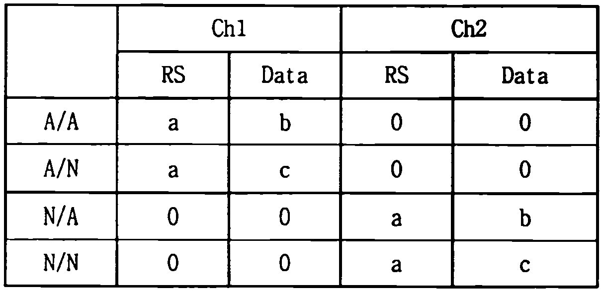
상기 표 4 에서, a, b, c 는 각각 미리 정해진 0이 아닌 특정 값일 수 있다. 단, b와 c는 성상도 상에서 서로간의 거리(distance)가 먼 것을 사용하는 것이 바람직하다. 예를 들어, a는 '+1' 로 사용되고, b와 c는 '+1' 과 '-1' 혹은 '-1' 과 '+1' 로써 사용될 수 있다. 표 4 의 예시에서 ACK/ACK를 전송할 경우는 자원 1 (=ch 1)에서 b로 변조하여 전송하고, ACK/NACK를 전송할 경우는 자원 1 (=ch 1)에서 c로 변조해서 전송함을 의미한다. 또한, NACK/ACK를 전송할 경우는 자원 2 (=ch 2)에서 b로 변조해서 전송하고, NACK/NACK를 전송할 경우는 자원 2 (=ch 2)에서 c로 변조해서 전송함을 의미한다.In Table 4, a, b, and c may each be a predetermined non-zero value. However, it is preferable that b and c have a distance from each other on the constellation. For example, a is used as '+1' and b and c can be used as '+1' and '-1' or '-1' and '+1'. In the example of Table 4, when ACK / ACK is transmitted, it is modulated with resource 1 (= ch 1) to b, and when ACK / NACK is transmitted, it is modulated with resource 1 (= ch 1) to c do. In addition, when NACK / ACK is transmitted, it is modulated from resource 2 (= ch 2) to b, and when NACK / NACK is transmitted, it is modulated from resource 2 (= ch 2) to c.
기존의 LTE 릴리즈-8/9에서 사용되는, TDD에서의 ACK/NACK 전송을 위한 채널 선택을 위한 매핑 관계는 다음의 표 5, 표 6 및 표 7 과 같이 정의되어 있다. LTE 릴리즈-8/9에서 TDD ACK/NACK 다중화(multiplexing)는 TDD ACK/NACK 채널 선택과 동일한 의미로 사용될 수 있지만, 후술하는 다중 반송파 지원 시스템(예를 들어, LTE-A 또는 LTE 릴리즈-10)에서는 그렇지 않다.Mapping relationships for channel selection for ACK / NACK transmission in TDD, which are used in existing LTE Release-8/9, are defined as shown in Tables 5, 6 and 7 below. TDD ACK / NACK multiplexing in LTE Release-8/9 can be used in the same sense as TDD ACK / NACK channel selection, but in a multi-carrier supporting system (e.g., LTE-A or LTE Release- Not so.
이하의 표 5, 표 6 및 표 7 에서 M 값은 TDD 시스템에서의 하향링크 관련 세트 인덱스 K: {k 0,k 1,…k M -1} (후술하는 표 12 에서와 같이 정의됨) 에 의해서 결정될 수 있다. 예를 들어, 표 5 에서 M=2인 경우, 공간(spatial) 번들링(즉, 복수개의 코드워드에 대한 ACK/NACK 번들링)을 포함한 2 가지 ACK/NACK 정보의 전달을 위해서 2 가지의 PUCCH 자원 (![]()
![]()
![]()
![]()
구체적으로, 단말은 서브프레임 n 에서 ACK/NACK 자원 ![]()
![]()
![]()
![]()


상기 표 5, 표 6 및 표 7 에서, HARQ-ACK(i)는 i-번째 데이터 유닛(0≤i≤3)의 HARQ ACK/NACK/DTX 결과를 나타낸다. DTX(Discontinuous Transmission)는 HARQ-ACK(i)에 대응하는 데이터 유닛의 전송이 없거나 단말이 HARQ-ACK(i)에 대응하는 데이터 유닛의 존재를 검출하지 못한 경우를 나타낸다. 본 명세서에서 HARQ-ACK은 ACK/NACK과 혼용된다. 각각의 데이터 유닛과 관련하여 최대 4개의 PUCCH 자원(즉, ![]()
![]()
![]()
![]()
![]()
![]()
한편, 본 발명의 적용과 관련되는 다중 반송파를 지원하는 LTE-A (또는 LTE 릴리즈-10) 시스템의 경우에 채널 선택 방법을 적용하기 위해서 이용하는 채널 선택 매핑 관계에 대한 특별한 제약이 없다. 예를 들어, 다음의 표 8 내지 표 10 과 같은 ACK/NACK 정보를 전송하기 위한 채널 선택 매핑 관계가 정의될 수 있다. 표 8 은 2-비트 ACK/NACK 을 위한 매핑 관계를, 표 9 는 3-비트 ACK/NACK 을 위한 매핑 관계를, 표 10 은 4-비트 ACK/NACK 을 위한 매핑 관계를 예시적으로 정의한 것이다.On the other hand, in the case of the LTE-A (or LTE Release-10) system supporting multi-carrier related to the application of the present invention, there is no particular restriction on the channel selection mapping relationship used for applying the channel selection method. For example, a channel selection mapping relation for transmitting ACK / NACK information as shown in the following Tables 8 to 10 can be defined. Table 8 is a mapping relationship for 2-bit ACK / NACK, Table 9 is a mapping relationship for 3-bit ACK / NACK, and Table 10 is an exemplary mapping relationship for 4-bit ACK / NACK.
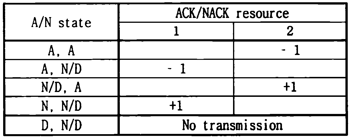


또는, 다음의 표 11 과 같은 1-비트 내지 4-비트 ACK/NACK 을 위한 채널 선택 매핑 관계를 정의할 수도 있다. 표 11 의 예시에서, 1-비트 ACK/NACK 정보를 전송하기 위해서 b0 를, 2-비트 ACK/NACK 정보를 전송하기 위해서 b0, b1 을, 3-비트 ACK/NACK 정보를 전송하기 위해서 b0, b1, b2 를, 4-비트 ACK/NACK 정보를 전송하기 위해서 b0, b1, b2, b3 를 생성 및 전송할 수 있다.Alternatively, a channel selection mapping relationship for 1-bit to 4-bit ACK / NACK as shown in Table 11 below may be defined. In the example of Table 11, b0 is transmitted to transmit 1-bit ACK / NACK information, b0 and b1 are transmitted to transmit 2-bit ACK / NACK information, and b0 and b1 , b2, and b0, b1, b2, b3 to transmit 4-bit ACK / NACK information.

다중 반송파 지원 시스템에서의 하향링크 전송에 대한 상향링크 확인응답 전송Transmission of uplink acknowledgment for downlink transmission in a multi-carrier supporting system
다중 반송파 또는 반송파 병합을 지원하는 시스템에 있어서 하향링크 자원은 DL CC(Component Carrier) 이고, 상향링크 자원은 UL CC 로 정의될 수 있다. 또한, 하향링크 자원 및 상향링크 자원의 조합을 셀(cell)이라고 칭할 수 있다. 다만, DL CC 와 UL CC 가 비대칭적으로 구성되는 경우에, 셀은 DL CC (또는 UL CC) 만을 지칭할 수도 있다. 예를 들어, 특정 단말이 하나의 서빙 셀(configured serving cell)을 설정 받는(configured) 경우에 1 DL CC와 1 UL CC를 가지게 된다. 그러나, 특정 단말이 두 개 이상의 서빙 셀을 설정 받는 경우에는 셀의 개수만큼의 DL CC를 가지며, UL CC의 개수는 DL CC 의 개수와 같거나 작을 수 있다. 또는, 특정 단말이 다수의 서빙 셀을 설정 받는 경우, DL CC의 수보다 UL CC가 더 많은 다중 반송파 환경이 지원될 수도 있다.In a system supporting multi-carrier or carrier wave combining, the downlink resource may be defined as a DL CC and the uplink resource may be defined as UL CC. In addition, a combination of downlink resources and uplink resources may be referred to as a cell. However, in the case where DL CC and UL CC are configured asymmetrically, a cell may refer only to DL CC (or UL CC). For example, when a particular UE is configured as a configured serving cell, it has 1 DL CC and 1 UL CC. However, when a specific terminal is set up with two or more serving cells, it has DL CC as many as the number of cells, and the number of UL CCs may be equal to or less than the number of DL CCs. Alternatively, when a specific terminal is set up with a plurality of serving cells, a multicarrier environment in which UL CC is larger than the number of DL CCs may be supported.
하향링크 자원의 반송파 주파수(셀의 중심 주파수)와 상향링크 자원의 반송파 주파수 사이의 연계(linkage)는 하향링크 자원 상에서 전송되는 시스템 정보(SI)에 의해서 지시(indicate)될 수 있다. 예를 들어, SIB2(System Information Block Type2)에 의해서 정의되는 연계(linkage)에 의해서 DL 자원과 UL 자원의 조합(combination)이 구성될 수 있다.The linkage between the carrier frequency of the downlink resource (the center frequency of the cell) and the carrier frequency of the uplink resource may be indicated by system information SI transmitted on the downlink resource. For example, a combination of DL resources and UL resources can be configured by a linkage defined by SIB2 (System Information Block Type 2).
이러한 정의에 따라, 반송파 병합(CA)은 반송파 주파수가 서로 다른 2 이상의 셀들의 병합이라고 칭할 수 있다. 즉, 특정 단말이 반송파 주파수가 서로 다른 2 개 이상의 서빙 셀들을 설정 받는 경우를 CA 환경이라고 수 있다. CA 를 지원하는 단말들에 대해서, 하나 이상의 SCell(Secondary cell)이 PCell(Primary Cell)과 함께 병합되어 사용됨으로써 증가된 대역폭이 지원될 수 있다.According to this definition, carrier merging (CA) can be referred to as merging of two or more cells with different carrier frequencies. That is, a case where a specific terminal sets two or more serving cells having different carrier frequencies may be referred to as a CA environment. For terminals supporting CA, one or more SCell (Secondary cell) may be used together with PCell (Primary Cell) to support the increased bandwidth.
여기서, 서빙 셀은 PCell 또는 SCell이 될 수 있다. RRC 연결이 설정된(RRC_CONNECTED) 단말이 CA 를 지원하지 못하는 경우에는 PCell 을 포함하는 하나의 서빙 셀만이 존재하게 된다. 또는, RRC_CONNECTED 단말이 CA 를 지원하는 경우에는, 서빙 셀이라는 용어는 PCell 및 SCell을 포함하는 하나 이상의 셀의 집합(set)를 지칭한다.Here, the serving cell may be PCell or SCell. If a terminal with RRC connection (RRC_CONNECTED) does not support CA, there will be only one serving cell including PCell. Alternatively, if the RRC_CONNECTED terminal supports CA, then the term serving cell refers to a set of one or more cells, including PCell and SCell.
PCell 은 CA 환경에서 설정된 서빙 셀들 중에서 제어관련 통신의 중심이 되는 셀이다. 단말이 초기 연결 확립 절차(initial connection establishment procedure), 연결 재확립 절차(connection re-establishment procedure) 또는 핸드오버 절차에서 지시 또는 이용된 셀이 PCell이 될 수 있다. 단말은 자신의 PCell에서만 PUCCH(Physical Uplink Control Channel)을 할당받고 전송할 수 있다. 또한, 단말은 시스템 정보 획득 및 변경에 대한 모니터링 절차를 PCell 에서만 수행할 수 있다. CA를 지원하는 단말에 대해서, 기지국은 mobilityControlInfo 를 포함하는 RRCConnectionReconfiguration 메시지를 이용하는 핸드오버 절차를 통해서만 PCell을 변경할 수 있다.PCell is the center cell of control related communication among the serving cells set in the CA environment. A cell may be a PCell in an initial connection establishment procedure, a connection re-establishment procedure, or a cell indicated or used in a handover procedure. A UE can allocate and transmit a Physical Uplink Control Channel (PUCCH) only in its own PCell. Also, the terminal can perform the monitoring procedure for acquiring and changing the system information only in the PCell. For a terminal supporting CA, the base station can change PCell only through a handover procedure using an RRCConnectionReconfiguration message including mobilityControlInfo.
다음으로, SCell 은 CA 환경에서 설정된 서빙 셀들 중에서 PCell을 제외한 나머지 셀들을 의미한다. SCell에서는 PUCCH가 존재하지 않는다. SCell 을 추가하는 경우에 기지국은 CA 를 지원하는 단말에게 전용 시그널링을 통해서 RRC_CONNECTED 상태의 해당 셀에서의 동작에 관련된 모든 시스템 정보를 제공할 수 있다. SCell 에 대해서, 시스템 정보의 변경은 하나의 RRCConnectionReconfiguration 메시지를 통한 해당 SCell의 해제(release) 및 추가(addition)에 의해서 수행될 수 있다. 기지국은 해당 SCell 에서 브로드캐스트 메시지에 포함된 파라미터와 상이한 파라미터를 가지는 전용 시그널링을 단말에게 전송할 수 있다. 초기 보안 활성화 절차(initial security activation procedure) 이후에, 기지국은 PCell(연결 확립 절차 동안 서빙 셀로서 설정되는 셀)에 추가적으로 하나 이상의 SCell을 단말에게 설정하여 줄 수 있다. PCell 은 보안 입력 및 상위 계층 시스템 정보를 제공하는 데에 이용되고, SCell 은 추가적인 하향링크 자원을 제공하고 필요한 경우 상향링크 자원을 제공하는 데에 이용될 수 있다. 기지국은 mobilityControlInfo 를 포함하거나 포함하지 않는 RRCConnectionReconfiguration 메시지를 이용한 RRC 연결 재설정 절차를 통하여 SCell 을 독립적으로 추가, 제거 또는 수정할 수 있다.Next, SCell refers to cells other than PCell among the serving cells set in the CA environment. There is no PUCCH in SCell. When SCell is added, the BS can provide all the system information related to the operation in the corresponding cell in the RRC_CONNECTED state through the dedicated signaling to the MS supporting the CA. For SCell, the change of system information can be done by release and addition of the corresponding SCell through one RRCConnectionReconfiguration message. The BS may transmit dedicated signaling to the UE with parameters different from those included in the broadcast message in the corresponding SCell. After the initial security activation procedure, the base station may set up one or more SCell to the terminal in addition to the PCell (cell set as a serving cell during the connection establishment procedure). PCell is used to provide security inputs and higher layer system information, and SCell can be used to provide additional downlink resources and to provide uplink resources as needed. The base station can independently add, remove or modify the SCell through an RRC connection reconfiguration procedure using an RRCConnectionReconfiguration message with or without mobilityControlInfo.
반송파 병합 환경에서의 RRC 관련 파라미터(parameter)/정보요소(Informatio Element; IE)로서 PhyCellId , SCellIndex , ServCellIndex 등이 정의될 수 있다. PhyCellId 는 0 내지 503 범위의 정수 값을 가질 수 있고, Cell 의 물리 계층 식별자로서 사용될 수 있다. SCellIndex 는 1 내지 7 범위의 정수 값을 가질 수 있고, SCell 의 식별자로서 사용될 수 있다. ServCellIndex 는 0 내지 7 범위의 정수 값을 가질 수 있고, 서빙셀(PCell 또는 SCell)의 식별자로서 사용될 수 있으며, 0 값은 PCell 에 적용되고, SCell 에 대해서는 SCellIndex가 적용될 수 있다. 즉, ServCellIndex에서 가장 작은(또는 가장 낮은) 셀 인덱스를 가지는 셀이 PCell 로서 정의될 수 있다. PhyCellId , SCellIndex , and ServCellIndex can be defined as RRC-related parameters / information elements (IEs) in a carrier merging environment. PhyCellId may have an integer value ranging from 0 to 503 and may be used as the physical layer identifier of the Cell. SCellIndex May have an integer value ranging from 1 to 7, and may be used as an identifier of SCell. ServCellIndex May have an integer value in the range of 0 to 7 and may be used as an identifier of a serving cell (PCell or SCell), a value of 0 may be applied to PCell, and a SCellIndex may be applied to SCell . That is, a cell having the smallest (or lowest) cell index in ServCellIndex can be defined as PCell.
요컨대, 반송파 병합에 있어서 다중 반송파들은 PCell과 SCell로 구분되며, 이는 단말-특정 파라미터(UE-specific parameter)이다. 특정 단말은 하나 이상의 설정된 서빙 셀을 가질 수 있으며, 복수의 설정된 서빙 셀이 존재하는 경우 셀들 중에서 셀은 PCell이 되고, 나머지 셀들은 SCells이 된다. 또한, TDD의 경우에 단말이 다수의 설정된 서빙 셀을 가질 때, 특정 DL 서브프레임에서 전송되는 PDSCH에 대한 ACK/NACK 이 어떤 UL 서브프레임을 통하여 전송되는지를 정의하는 UL-DL 설정(UL-DL configuration)은 모든 셀들에서 동일할 수 있다.In short, in the carrier combination, the multicarrier is divided into PCell and SCell, which is a UE-specific parameter. A specific UE may have one or more established serving cells, and if there are a plurality of established serving cells, the cells become PCells and the remaining cells become SCells. In the case of TDD, when the UE has a plurality of set serving cells, UL-DL setting (UL-DL) that defines which UL subframe the ACK / NACK for the PDSCH transmitted in a specific DL subframe is transmitted through configuration may be the same in all cells.
또한, 단말은 하나 이상의 CC들로부터 측정(measurement)된 CSI (Channel State Information) (CQI, RI, PMI 등을 통칭함), HARQ ACK/NACK 등의 상향링크 제어정보들을 미리 정해진 하나의 CC에서 기지국으로 전송할 수 있다. 예를 들어, 단말은 PCell DL CC와 SCell(s) DL CC로부터 수신된, 다수의 ACK/NACK 피드백이 필요한 경우에 이들 ACK/NACK 피드백을 모아서 (예를 들어, ACK/NACK 다중화(multiplexing) 또는 ACK/NACK 번들링(bundling) 등) PCell내 UL CC에서 하나의 PUCCH를 사용하여 전송할 수 있다.In addition, the UE may transmit uplink control information, such as CSI (Channel State Information) (collectively referred to as CQI, RI, PMI, etc.) and HARQ ACK / NACK, measured from one or more CCs, As shown in FIG. For example, the UE may collect (e.g., ACK / NACK multiplexing) these ACK / NACK feedbacks when multiple ACK / NACK feedbacks are received from PCell DL CC and SCell (s) ACK / NACK bundling, etc.) can be transmitted using one PUCCH in the UL CC in the PCell.
본 발명에서는, 복수개의 하향링크 전송에 대한 복수개의 ACK/NACK 이 하나의 상향링크 PUCCH를 통해서 전송되는 경우에, 복수개의 하향링크 전송을 구성하는 단위(하나 이상의 서브프레임 및/또는 하나 이상의 반송파)를 번들링 윈도우라고 칭한다. 즉, 시간 도메인 번들링이란 복수개의 서브프레임들에서의 하향링크 전송에 대한 ACK/NACK 을 번들링하는 것을 의미하고, CC 도메인 번들링이란 복수개의 CC들에서의 하향링크 전송에 대한 ACK/NACK 을 번들링하는 것을 의미하며, 시간/CC 도메인 번들링이란 복수개의 서브프레임들 및 복수개의 CC들에서의 하향링크 전송에 대한 ACK/NACK 을 번들링하는 것을 의미한다. ACK/NACK 번들링은 논리곱(logical AND) 연산에 의해 수행될 수 있지만, 이에 제한되는 것은 아니고, 논리합(logical OR) 등의 다른 방법을 통하여 수행될 수도 있다.In the present invention, when a plurality of ACK / NACKs for a plurality of downlink transmissions are transmitted through one uplink PUCCH, a unit (one or more subframes and / or one or more carriers) constituting a plurality of downlink transmissions, Is called a bundling window. That is, time domain bundling means bundling ACK / NACK for downlink transmission in a plurality of subframes, and CC domain bundling means bundling ACK / NACK for downlink transmission in a plurality of CCs And time / CC domain bundling means bundling ACK / NACK for downlink transmission in a plurality of subframes and a plurality of CCs. The ACK / NACK bundling may be performed by a logical AND operation, but is not limited thereto, and may be performed through other methods such as a logical OR.
또한, 실제로 논리곱(또는 논리합) 연산 등을 이용해서 시간 도메인 및/또는 CC 도메인 번들링이 수행되는 단위를, 실제 번들링 윈도우(real bundling window)라고 칭할 수 있다. 즉, 하나의 번들링 윈도우 내에는 하나 이상의 실제 번들링 윈도우가 존재할 수 있다. 다시 말하자면, 번들링 윈도우의 크기는 실제 번들링 윈도우 크기와 동일하거나 크다. 여기서, 하나의 하향링크 전송에 대한 복수개의 ACK/NACK 비트에 대한 공간(spatial) 번들링(즉, 복수개의 코드워드에 대한 ACK/NACK 번들링)은 번들링 윈도우 또는 실제 번들링 윈도우와 상관 없이 적용될 수 있다.In addition, a unit in which the time domain and / or the CC domain bundling is actually performed using a logical product (or logical sum) operation or the like can be referred to as a real bundling window. That is, there may be more than one actual bundling window in one bundling window. In other words, the size of the bundling window is equal to or greater than the actual bundling window size. Here, spatial bundling (i.e., ACK / NACK bundling for a plurality of codewords) for a plurality of ACK / NACK bits for one downlink transmission may be applied regardless of the bundling window or the actual bundling window.
3GPP LTE 시스템에서 정의하는, 하향링크 전송에 대한 ACK/NACK 피드백이 필요한 경우들에 대하여 설명한다. 여기서, 서브프레임 n 에서 ACK/NACK 이 전송되는 경우에, 해당 ACK/NACK 은 서브프레임 n-k 에서의 하향링크 전송에 대한 것이다.The case where ACK / NACK feedback for downlink transmission, which is defined in the 3GPP LTE system, is required will be described. Here, when ACK / NACK is transmitted in subframe n, the corresponding ACK / NACK is for downlink transmission in subframe n-k.
먼저, TDD 시스템의 경우에는 다음의 표 12 와 같이, 서브프레임 n 과 서브프레임 n-k 의 관계에 대해서 상기 표 1 의 UL-DL 구성들 별로 하향링크 관련 세트 인덱스 K: {k 0,k 1,…k M -1}가 주어질 수 있다.First, in the case of the TDD system, as shown in Table 12 below, the relationship between the subframe n and the subframe nk is determined according to the downlink-related set index K: { k 0 , k 1 , ..., k M -1 } may be given.

FDD의 경우에는, M은 항상 1이며, K는 항상 {k0}={4}이다.In the case of FDD, M is always 1, and K is always {k 0 } = {4}.
서브프레임 n-k 에서의 하향링크 전송에 대한 ACK/NACK 이 서브프레임 n 에서 전송되는 경우에, 서브프레임 n-k 에서의 하향링크 전송은 다음의 3 가지 경우 중 하나 이상에 대한 것일 수 있다.When ACK / NACK for downlink transmission in subframe n-k is transmitted in subframe n, downlink transmission in subframe n-k may be for one or more of the following three cases.
케이스 1 은, 서브프레임(들) n-k에서 검출된 PDCCH(들)에 의해 지시되는 PDSCH(들)에 대해 ACK/NACK 피드백이 필요한 경우이다. 여기서, k∈K이고, K는 서브프레임 인덱스(n)와 UL-DL 구성에 따라 달라지며, M개의 원소(element)로 이루어진다({k0, k1,...kM -1}). 아래의 표 12은 K: {k0, k1,...kM -1}를 예시한다. 케이스 1 은 일반적인 ACK/NACK 피드백이 필요한 PDSCH(들)에 관한 것이다. 이하의 설명에서는 케이스 1 을 'PDSCH 에 대한 ACK/NACK' 또는 'PDSCH with PDCCH에 대한 ACK/NACK'이라고 칭한다.
케이스 2 는 서브프레임(들) n-k 내 하향링크 SPS(Semi-Persistent Scheduling) 해제(release)를 지시하는 PDCCH(들)에 대한 ACK/NACK 피드백이 필요한 경우이다. 여기서, k∈K이고, K는 케이스 1에서 설명한 것과 동일하다. 케이스 2의 ACK/NACK은 SPS 해제를 위한 PDCCH(들)에 대한 ACK/NACK 피드백을 의미한다. 한편, DL SPS 해제에 대한 ACK/NACK 피드백은 수행되지만, SPS 활성화(activation)를 지시하는 PDCCH(들)에 대한 ACK/NACK 피드백은 수행되지 않는다. 이하의 설명에서는 케이스 2를 'DL SPS 해제 PDCCH에 대한 ACK/NACK'이라고 칭한다.
케이스 3 은 서브프레임(들) n-k에서 검출된 대응 PDCCH(들)이 없는 PDSCH(들) 전송에 대한 ACK/NACK 피드백이 필요한 경우이다. 여기서, k∈K이고, K는 케이스 1에서 설명한 것과 동일하다. 케이스 3는 PDCCH(들)이 없는 PDSCH(들)에 관한 것으로서 SPS PDSCH(들)에 대한 ACK/NACK 피드백을 의미한다. 이하의 설명에서는 케이스 3를 'DL SPS PDSCH에 대한 ACK/NACK'이라고 칭한다.
이하의 설명에서는, 대응되는 PDCCH를 갖는 PDSCH, DL SPS 해제를 위한 PDSCH, 대응되는 PDCCH 없는 PDSCH를 통칭하여, ACK/NACK 전송이 필요한 하향링크 전송이라고 한다.In the following description, a PDSCH having a corresponding PDCCH, a PDSCH for releasing a DL SPS, and a PDSCH without a corresponding PDCCH are collectively referred to as downlink transmission requiring ACK / NACK transmission.
위와 같은 하향링크 전송에 대한 ACK/NACK 이 전송이 다중 반송파 시스템에서 적용되는 경우에 대한 본 발명의 예시들에 대하여 이하에서 구체적으로 설명한다.Hereinafter, examples of the present invention in which ACK / NACK for downlink transmission is applied to a multi-carrier system will be described in detail.
설명의 편의를 위하여 다음과 같은 가정을 전제로 본 발명의 예시들에 대하여 설명한다. 그러나, 본 발명의 실시예들이 다음과 같은 가정 하에서만 실시될 수 있는 것은 아니다.For convenience of explanation, examples of the present invention will be described based on the following assumptions. However, the embodiments of the present invention can not be performed only on the following assumptions.
(1) 하나의 PCell과 하나 이상의 SCell(들)이 존재할 수 있다.(1) There can be one PCell and one or more SCell (s).
(2) 해당 PDCCH를 갖는 PDSCH(PDSCH with corresponding PDCCH)는 PCell 및 SCell(들)에 존재할 수 있다.(2) PDSCH with PDCCH (PDSCH with PDCCH) may exist in PCell and SCell (s).
(3) DL SPS 해제를 지시하는 PDCCH는 PCell에만 존재할 수 있다.(3) The PDCCH indicating the release of the DL SPS may exist only in the PCell.
(4) 해당 PDCCH가 없는 PDSCH(=SPS PDSCH)는 PCell에만 존재할 수 있다.(4) PDSCH (= SPS PDSCH) without corresponding PDCCH may exist only in PCell.
(5) PCell에서 SCell(들)로의 크로스-스케줄링은 지원될 수 있다.(5) Cross-scheduling from PCell to SCell (s) may be supported.
(6) SCell(들)에서 PCell로의 크로스-스케줄링은 지원되지 않는다.(6) Cross-scheduling from SCell (s) to PCell is not supported.
(7) SCell(들)에서 다른 SCell(들)로의 크로스-스케줄링은 지원될 수 있다.(7) Cross-scheduling from SCell (s) to other SCell (s) may be supported.
본 발명의 설명에서 시간 도메인 및/또는 CC 도메인 번들링이란 논리 AND 연산을 의미할 수 있으나, 논리 OR 연산 등의 다른 방법을 통하여 수행될 수도 있다. 즉, 이하에서 시간 도메인 혹은 CC 도메인 번들링이란 단일 PUCCH 포맷을 사용한 ACK/NACK 응답에서 다수의 서브프레임 혹은 다수의 CC에 걸친 다수의 ACK/NACK을 적은 비트수로 표현하기 위한 방법을 통칭한다. 즉, M-비트의 ACK/NACK 정보들을 N-비트(M≥N)로 표현하기 위한 임의의 방법을 통칭한다.In the description of the present invention, the time domain and / or CC domain bundling may mean a logical AND operation, but may also be performed through other methods such as a logical OR operation. That is, the time domain or the CC domain bundling is referred to as a method for representing a plurality of ACK / NACK over a plurality of subframes or multiple CCs in a small number of bits in an ACK / NACK response using a single PUCCH format. That is, any method for expressing M-bit ACK / NACK information as N-bit (M? N) is collectively referred to.
다중 반송파 및/또는 TDD 가 적용되는 시스템에서 복수개의 ACK/NACK 비트들은 PUCCH 포맷 1a/1b를 사용하는 채널 선택, PUCCH 포맷 3, 또는 PUCCH 포맷 3를 사용하는 채널 선택 등에 의해 전송될 수 있다. 상기 PUCCH 포맷들에 대한 PUCCH 자원 인덱스는 암묵적(implicit) 맵핑이 사용될 수도 있고, 명시적(explicit) 맵핑이 사용될 수도 있고, 또는 암묵적 맵핑과 명시적 맵핑이 복합적으로 사용될 수도 있다. 암묵적 맵핑에는, 예를 들어, 해당 PDCCH의 최저 CCE 인덱스를 기반으로 PUCCH 자원 인덱스를 유도하는 방법이 있다. 명시적 맵핑에는, 예를 들어, 해당 PDCCH 내 ARI(ACK/NACK Resource Indicator) 값에 의해서 해당 PUCCH 자원 인덱스를 RRC 구성 등에 의해 미리 정해진 세트 중에서 지시(indicate)하거나 유도하는 방법이 있다.In a system in which multicarrier and / or TDD is applied, a plurality of ACK / NACK bits may be transmitted by channel selection using PUCCH format 1a / 1b, channel selection using
본 발명과 관련하여, 복수개의 ACK/NACK 비트들을 전송하기 위한 새로운 PUCCH 포맷(예를 들어, 도 24 내지 도 27 과 관련하여 설명한 PUCCH 포맷 3)를 이용하는 경우에, PUCCH 포맷 3 의 자원 할당(resource allocation)은 명시적 자원 할당(explicit resource allocation)으로 수행되는 것을 기본으로 한다.In the context of the present invention, when using a new PUCCH format (e.g.,
구체적으로, PUCCH 포맷 3로 설정되어 있는 UE는 해당 포맷을 위한 직교 자원(orthogonal resource)을 명시적으로 (예를 들어, RRC 시그널링을 통해) 지시 받을 수 있다. 또한, RRC 구성 등에 의해 미리 정해진 직교 자원들 중에서, SCell로 전송되는 PDSCH를 위한 PDCCH 내의 ARI의 값에 의해 최종적인 PUCCH 자원을 결정할 수 있다. 이 때, ARI는 명시적으로 시그널링된 PUCCH 자원 값을 기준으로 하는 오프셋(offset) 값으로서 사용될 수도 잇고, 또는 하나 이상의 PUCCH 자원 세트 중에서 어느 것을 사용할 것인지 지시(indication)하는 용도로 사용될 수도 있다.Specifically, a UE set to
PDCCH 내에서 ARI 정보를 포함시키기 위해서, 기존의 PDCCH 에 정의되어 있는 필드를 ARI 용도로 재사용(reuse)하는 방안을 고려할 수 있다. PDCCH 에는 TPC(Trnansmit Power Control) 필드가 포함될 수 있다. TPC 필드의 원래 목적은 PUCCH 전송 전력을 제어하는 것이며, 2 비트의 값으로 구성될 수 있다.In order to include ARI information in the PDCCH, it is possible to consider reuse of a field defined in the existing PDCCH for ARI use. The PDCCH may include a TPC (Trnansmit Power Control) field. The original purpose of the TPC field is to control the PUCCH transmit power and may be configured with a value of two bits.
전술한 바와 같이, SCell에서만 ARI가 전송되도록 하는 경우에, SCell에 대한 PDCCH 내의 TPC(Trnansmit Power Control) 필드를 ARI 용도로 재사용할 수 있다. 한편, PCell에 대한 PDCCH 내의 TPC 필드는 본래 목적인 PUCCH 전송 전력 제어 용도로 사용될 수 있다.As described above, when the ARI is transmitted only in the SCell, the TPC (Trnansmit Power Control) field in the PDCCH for the SCell can be reused for the ARI use. On the other hand, the TPC field in the PDCCH for PCell can be used for PUCCH transmission power control purposes which are originally intended.
또한, LTE 릴리즈-10 시스템에서는 PCell의 PDSCH를 스케줄링하는 PDCCH 는 SCell에서 수신된 수 없으므로(즉, SCell의 PDCCH에 의해 PCell의 PDSCH을 교차-반송파 스케줄링하는 것이 허용되지 않으므로), UE가 PDSCH를 PCell에서만 수신한다는 의미는 PDCCH를 PCell에서만 수신한다(UE receives PDCCH only on PCell)는 의미와 등가일 수 있다.Further, in the LTE Release-10 system, since the PDCCH scheduling PDSCH of the PCell can not be received at the SCell (i.e., it is not allowed to perform cross-carrier scheduling of the PDSCH of the PCell by the SCell PDCCH) (PDCCH only on PCell) may be equivalent to the meaning.
RRC에 의해서 설정되는 명시적인 ACK/NACK 자원 할당은 다음과 같이 수행될 수 있다.The explicit ACK / NACK resource allocation set by the RRC can be performed as follows.
먼저, SCell 상에서의 PDSCH에 대응하는 PDCCH(즉, PDSCH 를 스케줄링하는 PDCCH)는, RRC에 의해 설정된 자원(들)로부터 특정 PUCCH 자원을 유도하는 정보(예를 들어, ARI)를 포함할 수 있다.First, the PDCCH corresponding to the PDSCH on the SCell (i.e., the PDCCH scheduling the PDSCH) may include information (e.g., ARI) that derives a specific PUCCH resource from the resource (s) set by the RRC.
다음으로, PDSCH에 대응하는 PDCCH 가 SCell들에서 수신되지 않고, PDSCH가 PCell 에서 수신되는 경우에는, 다음의 중 하나가 적용될 수 있다. 첫째는, LTE 릴리즈-8 에서 정의된 PUCCH 자원(즉, PUCCH 포맷 1a/1b 자원)이 사용될 수 있다. 둘째는, PCell 상에서의 PDSCH에 대응하는 PDCCH가, RRC에 의해 설정된 자원(들)로부터 특정 PUCCH 자원을 유도하는 정보(예를 들어, ARI)를 포함할 수 있다.Next, when the PDCCH corresponding to the PDSCH is not received at the SCells and the PDSCH is received at the PCell, one of the following can be applied. First, PUCCH resources defined in LTE Release-8 (i.e., PUCCH format 1a / 1b resources) may be used. Second, the PDCCH corresponding to the PDSCH on the PCell may include information (e.g., ARI) that derives a particular PUCCH resource from the resource (s) set by the RRC.
또한, UE는 SCell들에서 PDSCH에 대응하는 PDCCH들이 모두 동일한 ARI를 가지는 것으로 가정할 수 있다.In addition, the UE may assume that the PDCCHs corresponding to the PDSCH in the SCells all have the same ARI.
위와 같이 ARI 정보가 SCell 에서만 전송되도록 정의하는 경우에, 다중 반송파 및/또는 TDD 가 적용되는 시스템에서, UE가 PCell을 위한 PDSCH(들)만을 수신한 경우(또는 PCell에서만 PDCCH(들)을 수신한 경우)에는, SCell로부터 전송되는 ARI 정보를 알 수 없으므로, UE가 사용할 PUCCH 포맷(PUCCH 포맷 3)을 위한 자원 인덱스를 최종적으로 결정할 수 없는 문제가 발생하게 된다.In the case where the ARI information is defined to be transmitted only in the SCell as described above, in the system to which the multicarrier and / or TDD is applied, when the UE receives only the PDSCH (s) for the PCell (or receives only the PDCCH , There is a problem that the ARI information transmitted from the SCell can not be known, and thus the resource index for the PUCCH format (PUCCH format 3) to be used by the UE can not be finally determined.
본 발명에서는 이와 같은 문제를 해결하기 위하여, UE가 PCell을 위한 PDSCH(s) 만을 수신한 경우(또는 PCell에서만 PDCCH(s)를 수신한 경우)에도, PUCCH 포맷을 위한 자원 인덱스를 최종적으로 결정할 수 있는 방안들은 제안한다.In order to solve this problem, in the present invention, even if the UE receives only PDSCH (s) for PCell (or PDCCH (s) only in PCell), the UE can finally determine the resource index for the PUCCH format Suggestions are given.
본 발명의 다양한 예시들에서, UE가 PCell을 위한 PDSCH(s) 만을 수신한 경우(또는 PCell에서만 PDCCH(s)를 수신한 경우)를, 설명의 편의를 위하여 'PCell-only-receiving' 이라고 간략하게 표현한다. 여기서, PCell-only-receiving은 UE의 수신 입장에서 정의된 것이다. 또한, 다중 반송파 환경에서 본 발명이 적용되는 경우에, UE는 하나의 설정된 셀(configured cell)을 가질 수도 있고, 또는 다수의 설정된 셀들(configured cells)을 가질 수도 있다. UE가 하나의 설정된 셀을 가지는 경우에는 해당 셀이 PCell 이 되고, 다수의 설정된 셀들을 가지는 경우에 셀들은 하나의 PCell 과 하나 이상의 SCell(들)로 구성될 수 있다. 두 가지 경우 중 하나 또는 모두에서 본 발명이 적용될 수 있다. 즉, CA 환경 또는 비-CA(non-CA) 환경 모두에서 본 발명에서 정의하는 PCell-only-receiving 경우가 정의될 수 있다.In various examples of the present invention, when the UE receives only PDSCH (s) for PCell (or receives PDCCH (s) only in PCell), it is referred to as " PCell-only- . Here, PCell-only-receiving is defined in the reception position of the UE. Also, when the present invention is applied in a multi-carrier environment, the UE may have one configured cell or may have a plurality of configured cells. If the UE has one set cell, the corresponding cell is PCell, and if the UE has a plurality of set cells, the cells may be composed of one PCell and one or more SCell (s). The present invention can be applied to either or both of the two cases. That is, a PCell-only-receiving case defined in the present invention can be defined in both a CA environment and a non-CA (non-CA) environment.
또한, 전술한 바와 같이 복수개의 ACK/NACK 비트들을 전송하기 위해 사용되는 새로운 PUCCH 포맷, 즉, PUCCH 포맷 3 은, UE 가 하나의 설정된 셀을 가지는 경우에도 TDD 시스템에서 복수개의 하향링크 서브프레임을 통해 수신된 하향링크 전송에 대한 ACK/NACK 의 전송을 위해서 사용될 수 있다. 또는, PUCCH 포맷 3 은, UE 가 다수의 설정된 셀을 가지는 경우에 FDD 또는 TDD 시스템에서 사용될 수도 있다. 즉, PUCCH 포맷 3 은 반송파 병합(CA) 시스템에서 또는 비-반송파 병합(non-CA) TDD 시스템에서 사용될 수 있다.In addition, the new PUCCH format, i.e.,
또한, 본 발명의 다양한 예시들에서, PUCCH 포맷 3 을 위해 사용되는 자원들의 후보의 세트(resources candidate set)는 RRC에 의해 설정될(configured) 수 있다. 이러한 PUCCH 자원 후보 세트 중에서 특정 PUCCH 자원이 SCell의 ARI 정보(PDCCH 의 TPC 필드를 재사용함으로써 표현될 수 있음)의 값에 의해서 결정 또는 유도될 수 있음을 전제로 한다. 이를 간략하게 표현하자면, UE가 사용할 PUCCH 포맷 3 자원은 RRC 설정된 자원 후보 중에서 PDCCH에 포함된 ARI 에 의해 유도되는 것이라고 할 수 있다. 여기서, ARI는 X 비트 크기이며, 전술한 바와 같이 SCell 에서 PDCCH 내의 TPC 필드(2 비트 크기)를 재사용하여 ARI를 표현하는 경우에는 X=2 로 정의될 수 있다. 예를 들어, 2 비트 크기의 ARI를 사용하면, 4 개의 PUCCH 자원 후보 중 하나의 자원을 나타낼 수 있다.Also, in various examples of the present invention, the resources candidate set of resources used for
본 발명에서는 PUCCH 포맷 3 의 적용과 관련한 설명의 편의를 위하여, 1 개의 직교 자원을 필요로 하는 단일 안테나 전송을 가정하여 설명한다. 그러나, 본 발명은 이에 제한되는 것이 아니라, PUCCH 포맷 3 에 SORTD(spatial orthogonal-resource transmit diversity)와 같은 전송 다이버시티(Transmit Diversity) 기법과 같은 다중 안테나 전송 기법이 적용되는 경우에도 본 발명의 원리가 동일하게 적용될 수 있음은 자명하다.In the present invention, for convenience of description related to the application of the
전술한 사항을 종합하여, PUCCH 포맷 3 자원 할당에 대한 본 발명의 예시적인 가정에 대하여 설명한다.Taking all the above into account, an exemplary assumption of the present invention for
PUCCH 포맷 3 을 위한 자원을 ![]()
![]()
![]()
![]()
![]()
![]()
![]()
![]()
![]()
![]()
![]()
![]()
![]()
![]()
다음의 표 13 는 단일 안테나(single antenna) 전송의 경우에 PUCCH 포맷 3 을 위한 자원 할당을 예시적으로 나타낸다.The following Table 13 illustrates exemplary resource allocation for

이하에서는, 전술한 사항을 바탕으로, 본 발명의 다양한 예시들에 대하여 구체적으로 설명한다.In the following, various examples of the present invention will be described in detail based on the above description.
실시예Example 1 One
본 실시예 1 은 PCell-only-receiving 의 경우에서(즉, PCell을 위한 PDSCH(s) 만을 수신한 경우 또는 PCell에서만 PDCCH(s)를 수신한 경우에서), 미리 정의된(pre-defined) 자원 할당을 이용하는 방안에 대한 것이다.In the first embodiment, in the case of PCell-only-receiving (i.e., in the case of receiving only PDSCH (s) for PCell or PDCCH (s) only in PCell), pre- Quot; < / RTI >
PCell-only-receiving 의 경우에, PUCCH 포맷 3의 자원 인덱스를 미리 정해 놓는 것이 가능하다. 즉, 단말은 PCell-only-receiving이 아닌 경우에는 SCell을 통해 수신되는 ARI로부터 PUCCH 자원 인덱스를 유도할 수 있고, PCell-only-receiving인 경우에는 미리 정해진 PUCCH 자원 인덱스를 이용할 수 있다.In the case of PCell-only-receiving, it is possible to preset the
구체적으로, 단말이 PCell-only-receiving일 경우에 사용할 PUCCH 포맷 3 자원을 결정할 수 있도록, 새로운 인덱스를 미리 정해둘 수 있다. 이러한 새로운 인덱스는 SCell에서의 ARI와 동일한 의미를 가질 수 있다. 다시 말하자면, 이러한 인덱스는, RRC에 의해 설정된 자원 후보 세트 중 어느 하나를 지시(indicate)하는 용도로 사용될 수 있다. 이러한 인덱스는, 자원 후보 세트 중에서 특정 순서의(예를 들어, 첫 번째 또는 마지막 등) 자원을 지시하는 미리 정의되는 규칙(또는 특정 값)의 형태로 정의될 수 있다.Specifically, a new index can be determined in advance so that the
예를 들어, PCell-only-receiving일 경우에 PUCCH 포맷 3 자원을 결정할 수 있는 인덱스는, 시스템-특정 값(system-specific value)으로 정의될 수 있다. 또는, 이러한 인덱스는 기지국-특정 값(eNB-specific value), 또는 단말-특정 값(UE-specific value)으로서 RRC 설정될 수도 있다.For example, an index capable of determining a
도 28 은 PCell-only-receiving의 경우에 PUCCH 자원 결정을 위해 미리 정의된 자원 할당의 예시를 나타내는 흐름도이다.FIG. 28 is a flowchart illustrating an example of pre-defined resource allocation for PUCCH resource determination in case of PCell-only-receiving.
단계 S2810 에서, 단말은 상위-계층 설정(higher-layer configuration) (예를 들어, RRC 시그널링)을 통해서 PUCCH 포맷 3 를 위한 4 개의 자원을 포함하는 PUCCH 자원 후보 세트 ![]()
![]()
단계 S2820 에서, ACK/NACK 전송을 위해서 PUCCH 포맷 3을 사용하는 경우에, 단말은 PCell-only-receiving 인지 여부를 판정할 수 있다. 단계 S2820의 결과가 NO 인 경우(즉, PCell-only-receiving이 아닌 경우)에 단계 S2830 이 수행되고, 단계 S2820 의 결과가 YES 인 경우(즉, PCell-only-receiving인 경우)에 단계 S2840 이 수행된다.In step S2820, when the
단계 S2830 에서 단말은 SCell의 PDCCH(s) 내의 TPC 필드를 재사용하여 지시되는 ARI를 이용하여 4 가지의 PUCCH 자원 후보들 중에서 자신이 사용할 하나의 PUCCH 자원이 무엇인지를 (즉, 하나의 자원 인덱스를) 계산/선택할 수 있다.In step S2830, the UE reuses the TPC field in the PDCCH (s) of the SCell to determine what one PUCCH resource to use among the four PUCCH resource candidates (i.e., one resource index) Calculate / Select.
한편, 단계 S2840 에서는 SCell 에서의 PDCCH 이 수신이 없으므로, 단말은 미리-정의된 규칙(또는 미리-정의된 인덱스)에 의해서 4 개의 PUCCH 자원 후보 중에서 하나의 PUCCH 자원을 선택할 수 있다. 도 28 의 예시에서는 미리-정의된 규칙이 PUCCH 자원 후보 세트 내에서 마지막 PUCCH 자원 인덱스를 선택하는 것으로 정해져 있는 경우를 나타낸다. 즉, 단계 S2840 에서 단말은 ![]()
![]()
단계 S2830 또는 단계 S2840 이후, 단말은 계산/선택된 인덱스에 해당하는 자원을 이용하여 PUCCH 포맷 3를 통해서 ACK/NACK 정보를 전송할 수 있다.After step S2830 or step S2840, the UE can transmit ACK / NACK information through the
실시예Example 2 2
본 실시예 2 는 PCell-only-receiving 의 경우에서(즉, PCell을 위한 PDSCH(s) 만을 수신한 경우 또는 PCell에서만 PDCCH(s)를 수신한 경우에서), 추가적인(additional) 자원 인덱스를 미리 정하여 PUCCH 자원 할당에 이용하는 방안에 대한 것이다.The second embodiment differs from the first embodiment in that, in the case of PCell-only-receiving (i.e., when only the PDSCH (s) for PCell is received or the PDCCH (s) PUCCH resource allocation.
PCell-only-receiving의 경우에, PUCCH 포맷 3의 추가적인 자원 인덱스를 미리 정해 놓는 것이 가능하다. 즉, 단말은 PCell-only-receiving이 아닌 경우에는 SCell을 통해 수신되는 ARI로부터 PUCCH 자원 인덱스를 유도할 수 있고, PCell-only-receiving인 경우에는 미리 정해진 추가적인 PUCCH 자원 인덱스를 이용할 수 있다. 전술한 실시예 1 에서 미리 정해진 인덱스는 단말에게 설정되는 PUCCH 자원 후보 중의 하나에 대한 미리 정해진 인덱스이며, 본 실시예 2 에서는 단말에게 설정되는 PUCCH 자원 후보와 별도로 추가적인 자원 인덱스를 미리 정해두는 점에서 전술한 실시예 1 과 구별된다.In the case of PCell-only-receiving, it is possible to prescribe an additional resource index of
본 실시예에 따르면, 예를 들어, 2 비트 크기의 ARI 가 이용되는 경우에 4 개의 RRC 설정된 자원 후보 세트가 정의되는 경우에 있어서, RRC 시그널링을 통해 추가적인 하나의 자원 후보를 단말에게 알려줄 수 있다. 이는 RRC 설정된 자원 후보 세트가 5 개의 PUCCH 자원 인덱스로 구성되면서 그 중의 미리 정해진 하나의 자원 인덱스(예를 들어, 마지막 자원 인덱스)는 PCell-only-receiving 경우에만 사용되는 것으로 정의될 수 있다. 또는, 4 개의 RRC 설정된 자원 후보 세트와 별도로 PCell-only-receiving를 위한 하나의 자원 후보를 설정하는 것으로 정의될 수도 있다. 위 2 가지 경우 모두에서, PCell-only-receiving 의 경우에서만 사용하기 위한 (즉, SCell에서의 ARI에 의해 지칭되지 않는) 여분의 자원 인덱스가 단말에게 할당될 수 있다. 여기서, PCell-only-receiving를 위한 하나의 추가적인 자원 후보는, 기존의 RRC 설정되는 4 개의 자원 후보와 중복되지 않는 것으로 설정되는 것이 바람직하지만, 경우에 따라서는 중복으로 설정되는 것을 허용할 수도 있다.According to the present embodiment, for example, when four RRC set resource candidate sets are defined when 2-bit ARI is used, an additional resource candidate can be informed to the terminal through RRC signaling. It can be defined that the resource candidate set of the RRC is composed of five PUCCH resource indexes, and a predetermined one of the resource indexes (for example, the last resource index) is used only in the PCell-only-receiving case. Alternatively, it may be defined to set one resource candidate for PCell-only-receiving separately from the set of four RRC resource candidates. In both cases, an extra resource index (not referred to by ARI in SCell) for use only in the case of PCell-only-receiving may be allocated to the UE. Here, it is preferable that one additional resource candidate for PCell-only-receiving is set not to overlap with four existing resource candidates to be set in the existing RRC, but it may be allowed to be set to overlap in some cases.
도 29 는 PCell-only-receiving의 경우에 PUCCH 자원 결정을 위해 미리 정의된 추가적인 자원 할당의 예시를 나타내는 흐름도이다.FIG. 29 is a flowchart illustrating an example of pre-defined additional resource allocation for PUCCH resource determination in the case of PCell-only-receiving.
단계 S2910 에서, 단말은 상위-계층 설정(higher-layer configuration) (예를 들어, RRC 시그널링)을 통해서 5 개의 PUCCH 포맷 3 를 위한 자원을 포함하는 PUCCH 자원 후보 세트 {![]()
![]()
단계 S2920 에서, ACK/NACK 전송을 위해서 PUCCH 포맷 3을 사용하는 경우에, 단말은 PCell-only-receiving 인지 여부를 판정할 수 있다. 단계 S2920의 결과가 NO 인 경우(즉, PCell-only-receiving이 아닌 경우)에 단계 S2930 이 수행되고, 단계 S2920 의 결과가 YES 인 경우(즉, PCell-only-receiving인 경우)에 단계 S2940 이 수행된다.In step S2920, when the
단계 S2930 에서 단말은, 5 개의 PUCCH 자원 후보 세트 중에서 미리 정해진 소정의 규칙에 따라 결정된 4 개의 PUCCH 자원 후보들(예를 들어, 인덱스가 낮은 4 개의 PUCCH 자원 ![]()
![]()
![]()
![]()
한편, 단계 S2940 에서는 SCell 에서의 PDCCH 이 수신이 없으므로, 단말은 미리-정의된 규칙에 의해서 하나의 PUCCH 자원을 계산/선택할 수 있다. 여기서, 미리-정해진 규칙은, 예를 들어, RRC 설정된 5 개의 PUCCH 자원 후보 중에서 마지막 자원(![]()
![]()
단계 S2930 또는 단계 S2940 이후, 단말은 계산/선택된 인덱스에 해당하는 자원을 이용하여 PUCCH 포맷 3를 통해서 ACK/NACK 정보를 전송할 수 있다.After step S2930 or step S2940, the UE can transmit ACK / NACK information through the
실시예Example 3 3
본 실시예 3 은 PCell-only-receiving 의 경우에서(즉, PCell을 위한 PDSCH(s) 만을 수신한 경우 또는 PCell에서만 PDCCH(s)를 수신한 경우에서), DAI(Downlink Assignment Index)를 PUCCH 자원 할당에 이용하는 방안에 대한 것이다.In the case of PC-only-receiving (that is, PDCCH (s) is received only in PCcell or PDCCH (s) is received only in PCell), the downlink assignment index (DAI) It is about the method used for allocation.
전술한 실시예 1 및 2 에서는 추가적인 물리 계층 시그널링(예를 들어, PDCCH 시그널링) 없이 PCell-only-receiving 의 경우에서 PUCCH 포맷 3 을 위한 자원 인덱스를 유도하는 방안에 대하여 설명하였다. 본 실시예 3 에서는 SCell 에서의 수신이 없는 경우이므로 기존의 방식에서와 같이 SCell 상에서 ARI 를 수신할 수는 없지만, PCell 상에서 수신되는 물리 계층 시그널링 중에서 ARI 의 기능을 할 수 있는 정보를 정의하여 이용하는 방안에 대한 것이다. 구체적으로, 본 실시예에서는 PCell-only-receiving 의 경우에 PDCCH 내에 포함되는 DAI 정보를 ARI 정보로서 사용하는 방안에 대한 것이다.In the above-described first and second embodiments, a method of deriving a resource index for
PDCCH 내의 DAI 필드는 TDD 시스템에 대해서 정의되는 것이며, DL 할당(또는 PDSCH 스케줄링)에 대해 부여되는 인덱스이다. 단말이 복수개의 DL 할당(PDSCH)에 대한 ACK/NACK을 하나의 상향링크 서브프레임에서 전송함에 있어서, DAI 를 이용하여 ACK/NACK 전송될 DL 할당(PDSCH)의 개수에 대한 정보가 도출될 수 있다. 예를 들어, 단말이 기지국으로 복수개의 DL 할당(PDSCH)에 대한 ACK/NACK 신호를 (ACK/NACK 번들링 등을 이용하여) 전송함에 있어서, 복수개의 PDCCH 중에서 일부를 단말이 수신하지 못하는(즉, 놓치는) 경우가 발생할 수 있다. 이러한 경우, 단말은 자신이 놓친 PDCCH에 해당되는 PDSCH가 자신에게 전송된 사실 자체도 알 수 없으므로 ACK/NACK 생성에 오류가 발생할 수 있다. DAI를 이용하여 이러한 문제를 해결할 수 있다. 기존의 TDD 시스템에서, 예를 들어 N 개의 DL 서브프레임에 대해서 하나의 UL 서브프레임이 대응되어 있는 경우, N 개의 DL서브프레임 구간에 전송되는 PDCCH에 순차적으로 DAI를 부여(즉, 순차적으로 카운트)하면, 단말은 PDCCH에 있는 DAI 정보를 보고 이전까지의 PDCCH를 제대로 수신했는지 알 수 있게 된다.The DAI field in the PDCCH is defined for the TDD system and is an index given for DL allocation (or PDSCH scheduling). Information on the number of DL allocations (PDSCHs) to be ACK / NACK-transmitted using the DAI can be derived when the UE transmits ACK / NACK for a plurality of DL allocations (PDSCHs) in one uplink subframe . For example, when the UE transmits an ACK / NACK signal for a plurality of DL allocations (PDSCH) to the Node B (using ACK / NACK bundling, etc.), the UE can not receive some of the PDCCHs Missed) may occur. In this case, the UE can not know the fact that the PDSCH corresponding to the PDCCH that it missed has been transmitted to itself, so that an error may occur in ACK / NACK generation. DAI can be used to solve this problem. In an existing TDD system, for example, when one UL subframe corresponds to N DL subframes, DAI is sequentially given (i.e., sequentially counted) to PDCCHs transmitted in N DL subframe periods, , The UE can see the DAI information in the PDCCH and know whether the previous PDCCH was properly received.
본 실시예에서는 PUCCH 포맷 3 이 사용되는 경우에, PCell 의 PDCCH 내의 DAI 가 원래의 용도로 사용되지 않는 경우를 고려하여, DAI 를 PUCCH 자원 할당을 결정하는 ARI 의 용도로 재사용하는 것을 제안한다. 구체적으로, PUCCH 포맷 3가 TDD 시스템에서 사용된다고 해도, 시간-도메인 혹은 CC-도메인(또는 주파수-도메인)에서 번들링이 수행되지 않는 ACK/NACK 풀 멀티플렉싱(full multiplexing) 모드로 동작하는 경우에는 DAI 정보가 필요하지 않게 된다. 따라서, DAI 필드를 PCell-only-receiving 의 경우에 대한 ARI의 용도로 재사용할 수 있다.In the present embodiment, when
도 30 은 PCell-only-receiving의 경우에 PUCCH 자원 결정을 위해 DAI 필드를 ARI의 용도로 사용하는 예시를 나타내는 흐름도이다.30 is a flowchart illustrating an example of using a DAI field for ARI for PUCCH resource determination in case of PCell-only-receiving.
단계 S3010 에서, 단말은 상위-계층 설정(higher-layer configuration) (예를 들어, RRC 시그널링)을 통해서 PUCCH 포맷 3 를 위한 4 개의 자원을 포함하는 PUCCH 자원 후보 세트 {![]()
![]()
단계 S3020 에서, ACK/NACK 전송을 위해서 PUCCH 포맷 3을 사용하는 경우에, 단말은 PCell-only-receiving 인지 여부를 판정할 수 있다. 단계 S3020의 결과가 NO 인 경우(즉, PCell-only-receiving이 아닌 경우)에 단계 S3030 이 수행되고, 단계 S3020 의 결과가 YES 인 경우(즉, PCell-only-receiving인 경우)에 단계 S3040 이 수행된다.In step S3020, when the
단계 S3030 에서 단말은 SCell의 PDCCH(s) 내의 TPC 필드를 재사용하여 지시되는 ARI를 이용하여 4 가지의 PUCCH 자원 후보들 중에서 자신이 사용할 하나의 PUCCH 자원이 무엇인지를 (즉, 하나의 자원 인덱스를) 계산/선택할 수 있다.In step S3030, the UE reuses the TPC field in the PDCCH (s) of the SCell to determine what one PUCCH resource to use among the four PUCCH resource candidates (i.e., one resource index) Calculate / Select.
한편, 단계 S3040 에서는 SCell 에서의 PDCCH 이 수신이 없으므로, 단말은 PCell의 PDCCH 내의 DAI 필드를 재사용하여 지시되는 ARI를 이용하여 4 가지의 PUCCH 자원 후보들 중에서 자신이 사용할 하나의 PUCCH 자원이 무엇인지를 (즉, 하나의 자원 인덱스를) 계산/선택할 수 있다.In step S3040, since the PDCCH in the SCell is not received, the UE reuses the DAI field in the PDCCH of the PCell to determine what one PUCCH resource to use among the four PUCCH resource candidates by using the indicated ARI That is, one resource index).
단계 S3030 또는 단계 S3040 이후, 단말은 계산/선택된 인덱스에 해당하는 자원을 이용하여 PUCCH 포맷 3를 통해서 ACK/NACK 정보를 전송할 수 있다.After step S3030 or step S3040, the UE can transmit ACK / NACK information through the
실시예Example 3-1 3-1
본 실시예 3-1 은 PCell-only-receiving 의 경우에서(즉, PCell을 위한 PDSCH(s) 만을 수신한 경우 또는 PCell에서만 PDCCH(s)를 수신한 경우에서), 번들링된 서브프레임들 내에서 동일한 ARI 값을 적용하는 예시에 대한 것이다.In the case of PC-only-receiving (i.e., when only the PDSCH (s) for PCell is received or the PDCCH (s) is received only for PCell) For example, applying the same ARI value.
본 발명의 설명에서 번들링된 서브프레임들(또는 번들링 윈도우)이라는 용어는, 실제로 시간-도메인 또는 CC-도메인(또는 주파수-도메인)에서 번들링이 수행되는 단위를 의미하는 것이 아니라, 번들링 윈도우 내의 하향링크 서브프레임들에 대한 ACK/NACK 응답들이 하나의 상향링크 PUCCH로 전송되는 경우에 이러한 하향링크 서브프레임들로 구성된 하나의 단위를 의미한다.In the description of the present invention, the term bundled subframes (or bundling window) does not refer to a unit in which bundling is actually performed in the time-domain or CC-domain (or frequency-domain) And an ACK / NACK response for the subframes is transmitted in one uplink PUCCH, it means a unit composed of such downlink subframes.
예를 들어, LTE 릴리즈-8 TDD 시스템에서는 상기 표 12(하향링크 관련 세트 인덱스 K: {k 0,k 1,…k M -1}를 나타낸 표)과 같이 특정 UL 서브프레임 (서브프레임 n)에서 이전의 어떤 DL 서브프레임(들) (서브프레임 n-k) 에 대한 ACK/NACK 응답이 전송되는지를 정의하고 있다. 상기 표 12 의 예시를 빌려 번들링 서브프레임들을 설명하면, 특정 UL 서브프레임에서 특정 DL 서브프레임(들)에 대한 ACK/NACK 이 전송되는 경우에, 해당 특정 DL 서브프레임(들)을 번들링 서브프레임들이라고 칭한다. 예를 들어, UL-DL configuration 4 의 경우에, UL 서브프레임 2 에 대한 번들링된 서브프레임들은 DL 서브프레임 12, 8, 7, 11 이고, UL 서브프레임 3 에 대한 번들링된 서브프레임들은 DL 서브프레임 6, 5, 4, 7 이다.For example, LTE Release -8 TDD system in the above Table 12 (DL-related set index K: {k 0, k 1 , ... k M -1} the table shown) with a specific UL subframe as (subframe n) Defines an ACK / NACK response to which previous DL subframe (s) (subframe nk) is transmitted. To illustrate the bundling subframes with the example of Table 12 above, when an ACK / NACK for a specific DL subframe (s) is transmitted in a specific UL subframe, the specific DL subframe (s) Quot; For example, in the case of UL-
PUCCH 포맷 3 을 TDD에서 사용할 경우, 전술한 바와 같이 다수의 DL 서브프레임들에 대한 ACK/NACK 응답이 하나의 UL PUCCH를 통해 전송되는 경우가 발생할 수 있다. 이 경우, 전술한 실시예 3 에 따라 PCell-only-receiving 의 경우에, 복수개의 DL 서브프레임들에서 하나 이상의 PDCCH가 검출될 경우 각 PDCCH에서 가리키는 ARI(=DAI) 값이 서로 다르면, 그 중에서 어떤 ARI 값에 따라 PUCCH 자원을 계산/선택할지에 대한 불명료성이 존재하게 된다.When
따라서, 이와 같은 문제를 방지하기 위해서, 번들링된 서브프레임들 내에서는 PCell 에서 전송되는 PDCCH들의 ARI 값(즉, DAI 필드의 값)을 동일하게 유지시켜야 한다.Therefore, in order to prevent such a problem, the ARI value (i.e., the value of the DAI field) of the PDCCHs transmitted from the PCell must be maintained within the bundled subframes.
실시예Example 3-2 3-2
본 실시예 3-2는, 번들링된 CC들 내에서 동일한 ARI 값을 적용하는 예시에 대한 것이다.This embodiment 3-2 is for an example in which the same ARI value is applied in the bundled CCs.
본 발명의 설명에서 번들링된 CC들(또는 번들링 윈도우)이란 용어는, 실제로 시간-도메인 또는 CC-도메인(또는 주파수-도메인)에서 번들링이 수행되는 단위를 의미하는 것이 아니라, 번들링 유무와는 별개로 번들링 윈도우 내의 하향링크 CC들에 대한 ACK/NACK 응답들이 하나의 상향링크 PUCCH로 전송되는 경우에 이러한 하향링크 CC들로 구성된 하나의 단위를 의미한다. 예를 들어, ACK/NACK 풀 멀티플렉싱이 적용되는 경우에는, 번들링된 CC들은 단말에게 설정된 CC들의 개수와 동일한 의미로 사용될 수 있다.In the description of the present invention, the term bundled CCs (or bundling windows) does not mean a unit in which bundling is actually performed in the time-domain or CC-domain (or frequency-domain) And the ACK / NACK responses for the downlink CCs in the bundling window are transmitted on one uplink PUCCH. For example, when ACK / NACK full multiplexing is applied, the bundled CCs may be used in the same sense as the number of CCs set to the UE.
PUCCH 포맷 3 을 TDD 또는 FDD 시스템에서 사용할 경우, 전술한 바와 같이 다수의 DL CC들에 대한 ACK/NACK 응답이 하나의 UL PUCCH를 통해 전송되는 경우가 발생할 수 있다. 여기서, 다수의 DL CC들에 대한 ACK/NACK 응답이 전송된다는 의미는, PCell 및 하나 이상의 SCell 에서 하향링크 전송이 존재하는 경우에 해당할 수 있다. 이러한 경우, PCell 의 PDCCH 내의 ARI 값과 SCell 의 PDCCH 내의 ARI 값이 서로 다르면, 그 중에서 어떤 ARI 값에 따라 PUCCH 자원을 계산/선택할지에 대한 불명료성이 존재하게 된다.When the
따라서, 이와 같은 문제점을 사전에 방지하기 위해서, PCell에서 ARI 용도로 사용되는 필드(DAI 필드)의 값은, SCell에서의 ARI 용도로 사용되는 필드(TPC 필드)의 값과 동일하게 유지시켜야 한다.Therefore, in order to prevent such a problem in advance, the value of the field (DAI field) used for the ARI application in the PCell should be kept equal to the value of the field (TPC field) used for the ARI application in the SCell.
실시예Example 3-3 3-3
본 실시예 3-3 은, 번들링된 CC들 및 서브프레임들 내에서 동일한 ARI 값을 적용하는 예시에 대한 것이다.Embodiment 3-3 is for an example of applying the same ARI value in bundled CCs and subframes.
즉, 전술한 실시예 3-1 및 3-2 를 동시에 고려하는 경우 (예를 들어, 복수개의 CC들 및 복수개의 서브프레임들이 하나의 번들링 단위가 되는 경우), 각각의 Cell 또는 각각의 서브프레임에서의 ARI 값이 서로 다른 경우, PUCCH 자원 계산/선택의 불명료성이 발생할 수 있으므로, PCell 및 SCell 에서의 PDCCH 내의 ARI 가 동일하게 유지되는 것과 함께 복수개의 서브프레임들 상의 PDCCH 내의 ARI 역시 동일하게 유지되어야 한다.That is, when the above-described embodiments 3-1 and 3-2 are simultaneously considered (for example, when a plurality of CCs and a plurality of subframes are one bundling unit), each cell or each subframe The ARIs in the PDCCHs in the PCell and the SCell remain the same and the ARIs in the PDCCHs in the plurality of subframes must remain the same. do.
실시예Example 4 4
본 실시예 4 는, PCell-only-receiving 의 경우에서(즉, PCell을 위한 PDSCH(s) 만을 수신한 경우 또는 PCell에서만 PDCCH(s)를 수신한 경우에서), TPC 필드를 PUCCH 자원 할당에 이용하는 방안에 대한 것이다. 본 실시예 4 는 ACK/NACK 풀 멀티플렉싱이 적용되거나 적용되지 않는 경우 모두에 적용될 수 있다. 또한, 본 실시예 4 는 공간(spatial) 번들링(복수개의 코드워드에 대한 ACK/NACK 번들링)이 적용되거나 적용되지 않는 경우 모두에 적용될 수 있다.The fourth embodiment is different from the first embodiment in that the TPC field is used for PUCCH resource allocation in the case of PCell-only-receiving (i.e., in the case of receiving only the PDSCH (s) for PCell or the PDCCH It is about the plan.
전술한 실시예 3 에서는 추가적인 물리 계층 시그널링 없이 PCell-only-receiving 에서도 PUCCH 자원(예를 들어, PUCCH 포맷 3의 자원)의 자원 인덱스를 결정하는 방안에 대하여 설명하였다. 실시예 3 의 경우에는 DAI 가 원래의 용도(DL 할당(또는 PDSCH 스케줄링)에 대해 순차적으로 부여되는 인덱스의 용도)로 사용되지 않는 경우에 DAI 를 ARI 용도로 사용하는 예시에 대한 것이다. 따라서, PUCCH 포맷 3 가 TDD 시스템에서 사용되는 경우에, 시간-도메인 혹은 CC-도메인(또는 주파수-도메인)에서 번들링이 지원되는 경우에는, 올바른 ACK/NACK 정보 생성을 위해서 DAI 정보가 원래의 용도로 사용될 필요가 있다.In the third embodiment described above, a method of determining a resource index of a PUCCH resource (for example, a resource of PUCCH format 3) in PCell-only-receiving without additional physical layer signaling has been described. In the case of the third embodiment, the DAI is used for the ARI application in the case where the DAI is not used for the original use (the use of the index sequentially assigned to the DL allocation (or PDSCH scheduling)). Therefore, when bundling is supported in the time-domain or CC-domain (or frequency-domain) when
따라서, 본 실시예 4 에서는 PCell-only-receiving의 경우에 DAI 필드를 다른 용도로 재사용하지 않는다. 본 실시예 4 에서는 PCell-only-receiving의 경우에 PCell 상의 PDCCH(들) 내의 TPC 필드를 ARI 로 재사용하는 방안에 대하여 제안한다.Therefore, the fourth embodiment does not reuse the DAI field for other purposes in the case of PCell-only-receiving. In the fourth embodiment, a method of reusing the TPC field in the PDCCH (s) on the PCell as the ARI in the PCell-only-receiving case is proposed.
PCell-only-receiving이 아닌 경우(즉, SCell 상에서 PDCCH 전송이 있는 경우)에는, SCell 에서의 TPC 필드가 ARI 의 용도로 재사용됨은 전술한 바와 같다. 그러나, PCell-only-receiving의 경우에는 SCell 상에서 TPC 필드의 전송이 없으므로 올바른 ACK/NACK 전송을 위해 새로운 방안이 정의될 필요가 있다.If it is not PCell-only-receiving (i.e., there is a PDCCH transmission on SCell), the TPC field in SCell is reused for ARI as described above. However, in the case of PC-only-receiving, since there is no transmission of the TPC field on the SCell, a new scheme needs to be defined for correct ACK / NACK transmission.
본 실시예 4 에 따르면, PCell-only-receiving의 경우에, PCell 상에서 미리 정해진 규칙에 의해 결정된 특정 PDCCH(들) 내의 TPC 필드는 원래의 전송 전력 제어 용도로 사용되고, 나머지 PDCCH(들)의 TPC 필드는 ARI의 용도로 재사용할 수 있다. 단말은 PCell 상에서 이와 같이 미리 정해진 규칙에 의해서 결정된 특정 PDCCH(들)의 TPC 필드 만을 본래의 전력 제어 용도로 사용하고, PCell 상에서 이외의 PDCCH(들)이 수신될 경우에는 해당 PDCCH(들)의 TPC 필드는 ARI로 해석할 수 있다.According to the fourth embodiment, in the case of PCell-only-receiving, the TPC field in the specific PDCCH (s) determined by a predetermined rule on the PCell is used for the original transmission power control purpose and the TPC field Can be reused for the purposes of ARI. The UE uses only the TPC field of the specific PDCCH (s) determined by the predetermined rule on the PCell as the original power control purpose and when the PDCCH (s) other than the PCell is received, the TPC Fields can be interpreted as ARI.
여기서, TPC 필드가 원래의 용도로 사용되지 않는 경우에, 또는, 단말이 전력 제어 용도의 TPC 필드를 포함하는 PDCCH 를 놓치거나(miss) 기지국이 스케줄링하지 않는 경우에, 단말의 상향링크 전송 전력 결정에 대한 동적 제어 성능이 다소 감소될 수 있다. 그러나, PDCCH내 TPC 값은 절대값이 아니고 이전 전송 전력에 대한 상대적인 오프셋(offset) 값이며, 단말이 TPC 값을 한 두 번 업데이트 하지 않아도 기존에 설정된 전송 전력을 유지하게 될 뿐이다. 또한, PDCCH 내의 TPC 필드 값을 이용한 전송 전력 방안 이외에도, 보완적인 전력 제어 방안들이 마련되어 있다(이는 본 발명의 범위를 벗어난 부분이므로 구체적으로 설명하지 않는다). 따라서, TPC 값의 누락이 실질적으로 네트워크 성능에 큰 영향을 주지는 않게 된다.Here, when the TPC field is not used for the original purpose, or when the UE misses or does not schedule the PDCCH including the TPC field for power control purposes, the uplink transmission power determination of the UE The dynamic control performance can be somewhat reduced. However, the TPC value in the PDCCH is not an absolute value but an offset value relative to the previous transmission power, and the UE only maintains the previously set transmission power without updating the TPC value once or twice. In addition to the transmission power scheme using the TPC field value in the PDCCH, complementary power control schemes are provided (this is beyond the scope of the present invention and will not be described in detail). Therefore, the omission of the TPC value does not substantially affect the network performance.
본 실시예의 적용에 있어서, PCell 상에서 미리 정해진 규칙에 의해 하나 이상의 PDCCH(들)의 TPC 필드를 원래의 용도(전력 제어 용도)로 사용할 수 있다. 이하에서는 이러한 미리 정해진 규칙의 예시들에 대하여 설명한다.In the application of the present embodiment, the TPC field of one or more PDCCH (s) can be used for the original purpose (power control use) by predetermined rules on PCell. Hereinafter, examples of such predetermined rules will be described.
첫 번째 예시로서, 번들링 서브프레임 내에서 n 번째 서브프레임에서 전송되는 PDCCH 의 TPC 필드를 원래의 용도로 사용하는 것으로 정의할 수 있다. 여기서 n 은 번들링 서브프레임 중 일부 서브프레임(들)을 지시하는 값일 수 있다. 예를 들어, 번들링 서브프레임 중 하나의 서브프레임을 지시하는 경우에, n 은 0 번째 서브프레임 또는 마지막 서브프레임을 지시하는 값으로 정해질 수 있다. 또한, n 은 번들링되는 서브프레임들의 개수(또는 번들링 서브프레임의 크기)에 따라 상이하게 정해질 수 있다. 번들링되는 서브프레임들의 개수는, 예를 들어, 상기 표 12 에서 나타내는 바와 유사하게 1, 2, 3, 4 또는 9 이 될 수 있다. 또는, 새롭게 정의되는 번들링 방식에 따라 다른 개수의 서브프레임들이 번들링될 수도 있다. 또한, n 은 번들링 서브프레임 중의 복수개의 서브프레임들의 집합을 지시할 수도 있다. 예를 들어, n=0, 1 로 나타내는 경우에, 번들링 서브프레임 중에서 0 번째 및 1 번째 서브프레임에서 전송되는 PDCCH 의 TPC 필드를 원래의 용도로 사용하는 것을 나타낼 수 있다. 이와 같이, n 이 다수의 값을 가지는 경우에, 후술하는 폴-백 테스트(fall-back test)를 위한 수신된 PDCCH(received PDCCH)의 개수도 n 값의 개수만큼 증가된다. 예를 들어, n 이 2 개의 값을 가지면, 폴-백 테스트를 위한 수신된 PDCCH 의 개수도 2 개가 되어야 한다. 이하의 본 발명의 설명에서는 편의상 n 이 하나의 값을 가지는 경우를 예를 들어 설명한다.As a first example, it can be defined that the TPC field of the PDCCH transmitted in the n < th > subframe in the bundling subframe is used for its original purpose. Where n may be a value indicating some of the subframe (s) of the bundling subframe. For example, in the case of indicating one subframe among the bundling subframes, n may be set to a value indicating the 0th subframe or the last subframe. Also, n may be determined differently depending on the number of subframes to be bundled (or the size of the bundling subframe). The number of subframes to be bundled may be 1, 2, 3, 4 or 9, for example, as shown in Table 12 above. Alternatively, a different number of subframes may be bundled according to a newly defined bundling scheme. Also, n may indicate a set of a plurality of subframes in a bundling subframe. For example, when n = 0, 1, it may indicate that the TPC field of the PDCCH transmitted in the 0th and 1st subframes of the bundling subframe is used for its original use. Thus, when n has a plurality of values, the number of received PDCCHs (received PDCCHs) for a fall-back test described later is also increased by the number of n values. For example, if n has two values, the number of received PDCCHs for the fallback test should also be two. In the following description of the present invention, it is assumed that n has a single value for convenience.
두 번째 예시로서, 번들링 서브프레임 내에서 n 번째 DAI 값을 가지는 PDCCH에서 TPC 필드가 원래의 용도로 사용되는 것으로 정의할 수 있다. 여기서, n 은 0, 1, 2, 3, ... 중에서 하나의 값을 가질 수 있다. 또는, DAI 값이 1, 2, 3, 4, ... 와 같이 해석되는 경우에는 n=1, 2, 3, 4, ... 중에서 하나의 값으로 정해질 수 있다. 이러한 경우, ACK/NACK 풀 멀티플렉싱 모드(시간-도메인 또는 CC-도메인(또는 주파수-도메인) 번들링이 적용되지 않는 경우)에서도, PCell 상의 PDCCH(들) 내에 DAI 필드가 포함될 수 있다. 또한, n 은 복수개의 값의 집합의 형태로 정해질 수도 있다. 예를 들어, n=0, 1 와 같이 주어지는 경우에, 0 번째와 1 번째 DAI 값을 가지는 PDCCH들에서 TPC 필드가 원래의 용도로 사용됨을 나타낼 수 있다. 또는, DAI 값이 1 부터 시작하는 것으로 해석되는 경우에는, n=1, 2 과 같이 주어지는 경우에, 1 번째와 2 번째 DAI 값을 가지는 PDCCH들에서 TPC 필드가 원래의 용도로 사용됨을 나타낼 수 있다. 이와 같이, n 이 다수의 값을 가지는 경우에, 후술하는 폴-백 테스트(fall-back test)를 위한 수신된 PDCCH(received PDCCH)의 개수도 n 값의 개수만큼 증가된다. 예를 들어, n 이 2 개의 값을 가지면, 폴-백 테스트를 위한 수신된 PDCCH 의 개수도 2 개가 되어야 한다. 이하의 본 발명의 설명에서는 편의상 n 이 하나의 값을 가지는 경우를 예를 들어 설명한다.As a second example, it can be defined that the TPC field in the PDCCH with the nth DAI value in the bundling subframe is used for its original purpose. Here, n may have a value of 0, 1, 2, 3, .... Alternatively, when the DAI value is interpreted as 1, 2, 3, 4, ..., n = 1, 2, 3, 4, .... In this case, the DAI field may be included in the PDCCH (s) on the PCell, even in the ACK / NACK full multiplexing mode (when no time-domain or CC-domain (or frequency-domain) bundling is applied). Also, n may be defined as a set of a plurality of values. For example, when given as n = 0, 1, it can be shown that the TPC field is used for the original purpose in the PDCCHs having the 0th and 1st DAI values. Alternatively, when the DAI value is interpreted as starting from 1, given that n = 1, 2, it can be indicated that the TPC field is used for the original purpose in the PDCCHs having the first and second DAI values . Thus, when n has a plurality of values, the number of received PDCCHs (received PDCCHs) for a fall-back test described later is also increased by the number of n values. For example, if n has two values, the number of received PDCCHs for the fallback test should also be two. In the following description of the present invention, it is assumed that n has a single value for convenience.
상기 두 번째 예시에 있어서, DAI 값은 2 비트 크기를 가지고 단말에게 할당되는 PDCCH(들)에 대한 연속된(순차적인) 카운터의 의미를 가질 수 있다. 실제 전송되는 DAI 필드의 값은 0, 1, 2, 3 (2 비트 값으로 표현하면 00, 01, 10, 11) 중 하나가 될 수 있고, 이는 각각 단말에서 DAI 값 1, 2, 3, 4 로 해석될 수 있다. 이를 실제 전송되는 DAI 값의 관점과 단말이 해석하는 DAI 값의 관점에서 나누어 설명하면 다음과 같다.In the second example, the DAI value may have the meaning of a sequential (sequential) counter for the PDCCH (s) allocated to the UE with a size of 2 bits. The actual DAI field value can be one of 0, 1, 2, 3 (00, 01, 10, 11 in the case of 2-bit values) . ≪ / RTI > This will be described below in terms of the DAI value actually transmitted and the DAI value interpreted by the UE.
실제 전송되는 DAI 필드의 값이 0, 1, 2 또는 3 이고, 단말은 이를 각각 1, 2, 3 또는 4 번째 PDCCH로 해석할 수 있다. 이러한 경우, 실제 전송되는 DAI 값 관점에서, 특정 단말에서 n=0 (0, 1, 2, 3 의 세트 중에서)인 경우가 첫 번째 PDCCH를 의미하게 된다.The value of the actual DAI field is 0, 1, 2, or 3, and the UE can interpret it as a 1, 2, 3, or 4th PDCCH, respectively. In this case, in the case of n = 0 (in the set of 0, 1, 2, 3) in the specific terminal in terms of the actual transmitted DAI value, it means the first PDCCH.
실제 전송되는 DAI 값이 0, 1, 2 또는 3 이고, 단말은 이를 각각 1, 2, 3 또는 4 번째 PDCCH로 해석할 수 있다. 이러한 경우, 단말에서 해석되는 DAI 값 관점에서, 특정 단말에서 n=1 (1, 2, 3, 4의 세트 중에서)인 경우가 첫 번째 PDCCH를 의미하게 된다.The actual DAI value is 0, 1, 2, or 3, and the UE can interpret it as a 1, 2, 3, or 4th PDCCH, respectively. In this case, from the viewpoint of the DAI value interpreted by the UE, n = 1 (in the set of 1, 2, 3, 4) in a specific terminal means the first PDCCH.
정리하자면, PDCCH 에 포함되는 실제 DAI 필드의 값 00, 01, 10, 11 은, 단말이 해석하는 DAI 값 1, 2, 3, 4 에 각각 매핑될 수 있다.In summary, the
상기 예시들에서와 같이 n 값에 의해 결정되는, n 번째 서브프레임의 PDCCH(들) 또는 DAI=n 인 PDCCH(들)에서의 TPC 필드는 원래의 용도(전력 제어 용도)로 사용되고, 그 이외의 PDCCH(들)에서의 TPC 필드는 ARI 의 용도로 재사용될 수 있다.The TPC field in the PDCCH (s) of the n < th > subframe or the PDCCH (s) of DAI = n, determined by the value of n, as in the above examples, is used for its original use (power control use) The TPC field in the PDCCH (s) can be reused for the purposes of ARI.
도 31 은 PCell-only-receiving의 경우에 PUCCH 자원 결정을 위해 TPC 필드를 ARI의 용도로 사용하는 예시를 나타내는 흐름도이다. 도 31 의 예시에서, 미리 정의된 규칙에 따라 결정된 특정 하나의 PDCCH의 TPC 필드는 원래의 용도로 사용되고 나머지 PDCCH(들)의 TPC 필드는 ARI 로 재사용되는 경우를 가정한다.FIG. 31 is a flowchart illustrating an example of using a TPC field for the purpose of ARI for PUCCH resource determination in case of PCell-only-receiving. In the example of FIG. 31, it is assumed that the TPC field of a specific PDCCH determined according to a predefined rule is used for its original use and the TPC field of the remaining PDCCH (s) is reused as an ARI.
단계 S3110 에서, 단말은 상위-계층 설정(higher-layer configuration) (예를 들어, RRC 시그널링)을 통해서 PUCCH 포맷 3 를 위한 4 개의 자원을 포함하는 PUCCH 자원 후보 세트 {![]()
![]()
단계 S3120 에서, ACK/NACK 전송을 위해서 PUCCH 포맷 3을 사용하는 경우에, 단말은 PCell-only-receiving 인지 여부를 판정할 수 있다. 단계 S3120의 결과가 NO 인 경우(즉, PCell-only-receiving이 아닌 경우)에 단계 S3130 이 수행되고, 단계 S3120 의 결과가 YES 인 경우(즉, PCell-only-receiving인 경우)에 단계 S3140 이 수행된다.In step S3120, if the
단계 S3130 에서 단말은 SCell의 PDCCH(s) 내의 TPC 필드를 재사용하여 지시되는 ARI를 이용하여 4 가지의 PUCCH 자원 후보들 중에서 자신이 사용할 하나의 PUCCH 자원이 무엇인지를 (즉, 하나의 자원 인덱스를) 계산/선택할 수 있다.In step S3130, the UE reuses the TPC field in the PDCCH (s) of the SCell to determine what one of the four PUCCH resource candidates is to use (i.e., one resource index) Calculate / Select.
한편, 단계 S3140 에서 단말은 수신된 PDCCH(received PDCCH)의 개수가 1 인지 여부를 판정할 수 있다. 단계 S3140 은 SCell 에서의 PDCCH 이 수신이 없는 경우에 수행되므로, 수신된 PDCCH 의 개수는 PCell 에서 수신된 PDCCH 의 개수를 의미한다. 단계 S3140의 결과가 YES 인 경우(즉, PCell 에서 수신된 PDCCH 의 개수 = 1 인 경우)에 단계 S3150 이 수행되고, 단계 S3140의 결과가 NO 인 경우(즉, PCell 에서 수신된 PDCCH 의 개수 > 1 인 경우)에 단계 S3160 이 수행된다.On the other hand, in step S3140, the UE can determine whether the number of received PDCCHs (received PDCCHs) is 1 or not. In step S3140, since the PDCCH in the SCell is not received, the number of received PDCCHs means the number of PDCCHs received in the PCell. If the result of step S3140 is YES (that is, if the number of PDCCHs received in the PCell = 1), step S3150 is performed. If the result of step S3140 is NO (i.e., the number of PDCCHs received in the PCell is > Step S3160 is performed.
단계 S3150 에서, 단말이 PCell 에서 하나의 PDCCH만을 수신한 경우에, 단말은 그 PDCCH 의 TPC 필드는 원래의 용도(전력 제어 용도)로 사용되고, 다른 PDCCH 가 없으므로 단말은 ARI 값을 수신하지 못한 것으로 간주할 수 있다. 이 경우에는 단말은 기존의 LTE 릴리즈-8 모드로 동작하는 것으로 정의할 수 있다. 이를 폴-백(fall-back) 모드로 동작하는 것이라고 칭할 수 있다. 폴-백 모드는 기존에 정의된 PUCCH 포맷 1a/1b 을 이용한 ACK/NACK 전송 동작과 동일하므로, 이에 대한 구체적인 설명은 생략한다. 또한, 단계 S3140 에서 수신된 PDCCH 의 개수가 1 인지 여부를 판정하는 것을, 폴-백 모드의 적용 여부를 판정한다는 의미에서, 폴-백 테스트라고 칭할 수 있다.In step S3150, when the UE receives only one PDCCH in the PCell, the UE determines that the TPC field of the PDCCH is used for the original use (power control use) and the UE does not receive the ARI value because there is no other PDCCH can do. In this case, the UE can be defined as operating in the existing LTE Release-8 mode. This can be referred to as operating in a fall-back mode. The poll-back mode is the same as the ACK / NACK transmission operation using the PUCCH format 1a / 1b defined previously, so a detailed description thereof will be omitted. The determination of whether the number of PDCCHs received in step S3140 is 1 can be referred to as a fall-back test in the sense of determining whether the fall-back mode is applied or not.
한편, 단계 S3160 에서 단말은 PCell 상에서 수신된 PDCCH 의 개수가 1 보다 큰 경우이므로, 그 중 하나의 PDCCH 에서의 TPC 필드는 원래의 용도로 사용하고 나머지 PDCCH(들)의 TPC 필드는 ARI 의 용도로 해석할 수 있다. 이에 따라, 단말은 PCell 의 PDCCH 내의 TPC 필드를 재사용하여 지시되는 ARI 를 이용하여 4 가지의 PUCCH 자원 후보들 중에서 자신이 사용할 하나의 PUCCH 자원이 무엇인지를 (즉, 하나의 자원 인덱스를) 계산/선택할 수 있다.On the other hand, in step S3160, since the number of PDCCHs received on the PCell is larger than one in step S3160, the TPC field in one PDCCH is used for the original purpose and the TPC field in the remaining PDCCH (s) is used for ARI Can be interpreted. Accordingly, the UE reuses the TPC field in the PDCCH of the PCell to calculate / select which one of the four PUCCH resource candidates is to be used (i.e., one resource index) .
단계 S3130 또는 단계 S3160 이후, 단말은 계산/선택된 인덱스에 해당하는 자원을 이용하여 PUCCH 포맷 3를 통해서 ACK/NACK 정보를 전송할 수 있다.After step S3130 or step S3160, the UE can transmit ACK / NACK information through the
도 31 의 예시에서는, 단말에서 수신된(또는 검출된) PDCCH 의 개수만을 검사하고, 수신된 PDCCH 의 개수가 1 인 경우에 해당 PDCCH 의 TPC 필드는 원래의 용도로 사용되는 PDCCH 임을 가정한 동작에 대하여 설명하였다.In the example of FIG. 31, only the number of PDCCHs received (or detected) by the UE is examined. When the number of received PDCCHs is 1, the TPC field of the PDCCH is assumed to be a PDCCH used for the original purpose Respectively.
그러나, 수신된 PDCCH 의 개수가 1 인 경우에 그 PDCCH 가, TPC 필드를 원래의 용도로 사용하는 PDCCH 일 수도 있고, 또는, TPC 필드가 ARI 용도로 재사용되는 PDCCH일 수도 있다. 따라서, 수신된 PDCCH 의 개수가 1 이라고 해서 무조건 폴-백 모드로 동작하기 보다는, 이에 대해서 구체적으로 판정하는 것이 바람직할 수 있다.However, if the number of PDCCHs received is one, the PDCCH may be a PDCCH that uses the TPC field for its original purpose, or the PDCCH where the TPC field is reused for ARI purposes. Therefore, it may be preferable to specifically determine the number of received PDCCHs rather than operating in the unconditional fallback mode.
도 32 는 PCell-only-receiving의 경우에 PUCCH 자원 결정을 위해 TPC 필드를 ARI의 용도로 사용하는 다른 예시를 나타내는 흐름도이다. 도 32 의 예시에서, 미리 정의된 규칙에 의해 결정된 특정 하나의 PDCCH의 TPC 필드는 원래의 용도로 사용되고 나머지 PDCCH(들)의 TPC 필드는 ARI 로 재사용되는 경우를 가정한다.32 is a flowchart showing another example of using the TPC field for the purpose of ARI for PUCCH resource determination in case of PCell-only-receiving. In the example of FIG. 32, it is assumed that the TPC field of a particular PDCCH determined by a predefined rule is used for its original purpose and the TPC field of the remaining PDCCH (s) is reused as an ARI.
도 32 의 예시에 대한 설명에 있어서, 도 31 과 중복되는 동작(단계 S3210, S3220, S3230, S3240)에 대한 설명은 생략한다.In the description of the example of Fig. 32, the description of the operations (steps S3210, S3220, S3230, S3240) which are duplicated in Fig. 31 will be omitted.
단계 S3250 은 단계 S3240 의 결과가 YES 인 경우(즉, PCell 에서 수신된 PDCCH 개수가 1 인 경우)에 수행된다. 단계 S3250 에서는 수신된 하나의 PDCCH 가 미리 정의된 PDCCH 인지(즉, TPC 필드가 원래의 용도로 사용되는 PDCCH 인지) 여부를 판정한다. 예를 들어, 수신된 PDCCH가, 번들링 서브프레임 내에서 첫 번째 서브프레임 상의 PDCCH 인지 여부를 판정할 수 있다. 다른 예시로서, 수신된 PDCCH가, DAI=1 인 PDCCH 인지 여부를 판정할 수 있다. 그 결과가 YES 인 경우에는 단계 S3260 이 수행되고, NO 인 경우에는 단계 S3270 이 수행된다.Step S3250 is performed when the result of step S3240 is YES (i.e., when the number of PDCCHs received in PCell is one). In step S3250, it is determined whether one received PDCCH is a predefined PDCCH (i.e., whether the TPC field is a PDCCH used for the original purpose). For example, it may be determined whether the received PDCCH is a PDCCH on the first subframe in the bundling subframe. As another example, it may be determined whether the received PDCCH is a PDCCH with DAI = 1. If the result is YES, step S3260 is performed, and if NO, step S3270 is performed.
단계 S3260 에서는 수신된 하나의 PDCCH 에서 TPC 필드가 원래의 용도로 사용되어야 하므로, 단말은 ARI 값을 알 수 없는 것으로 간주하고 폴-백 모드로 동작(PUCCH 포맷 1a/1b 을 이용하여 ACK/NACK 전송)할 수 있다.In step S3260, the TPC field in the received PDCCH is used for the original purpose. Therefore, the terminal regards the ARI value as unknown and operates in the fallback mode (ACK / NACK transmission using the PUCCH format 1a / )can do.
단계 S3270 은 단계 S3240 의 결과가 NO 인 경우에 수행될 수 있다. 즉, 수신된 PDCCH의 개수 > 1 인 경우에, TPC 필드가 원래의 용도로 사용되는 PDCCH 는 하나만 존재하는 것으로 가정하였으므로, 단말은 적어도 하나의 PDCCH 의 TPC 필드가 ARI 로 재사용되는 것을 알 수 있다. 단말은 해당 PDCCH 의 TPC 필드로부터 ARI 값을 이용하여, 4 가지의 PUCCH 자원 후보들 중에서 자신이 사용할 하나의 PUCCH 자원이 무엇인지를 (즉, 하나의 자원 인덱스를) 계산/선택할 수 있다.Step S3270 can be performed when the result of step S3240 is NO. That is, when the number of received PDCCHs is > 1, it is assumed that there is only one PDCCH in which the TPC field is used for the original purpose, so that the UE can know that the TPC field of at least one PDCCH is reused as an ARI. The UE can calculate / select what one PUCCH resource to use (i.e., one resource index) from among four PUCCH resource candidates by using the ARI value from the TPC field of the corresponding PDCCH.
또는, 단계 S3270 은 단계 S3250 의 결과가 NO 인 경우에도 수행될 수 있다. 즉, 수신된 PDCCH 의 개수가 1 인 경우에, 해당 PDCCH 가 TPC 필드를 원래의 용도로 사용하는 PDCCH 가 아닌 경우이므로, 단말은 해당 하나의 PDCCH 의 TPC 필드를 ARI 용도로 재사용함을 알 수 있다. 단말은 해당 PDCCH 의 TPC 필드로부터 ARI 값을 이용하여, 4 가지의 PUCCH 자원 후보들 중에서 자신이 사용할 하나의 PUCCH 자원이 무엇인지를 (즉, 하나의 자원 인덱스를) 계산/선택할 수 있다.Alternatively, step S3270 can be performed even if the result of step S3250 is NO. That is, when the number of PDCCHs received is 1 and the corresponding PDCCH is not a PDCCH that uses the TPC field as its original purpose, the UE can know that the TPC field of the PDCCH is reused for the ARI . The UE can calculate / select what one PUCCH resource to use (i.e., one resource index) from among four PUCCH resource candidates by using the ARI value from the TPC field of the corresponding PDCCH.
단계 S3270 이후, 단말은 계산/선택된 인덱스에 해당하는 자원을 이용하여 PUCCH 포맷 3를 통해서 ACK/NACK 정보를 전송할 수 있다.After step S3270, the UE can transmit ACK / NACK information through the
실시예Example 4-1 4-1
본 실시예 4-1 은 PCell-only-receiving 의 경우에서(즉, PCell을 위한 PDSCH(s) 만을 수신한 경우 또는 PCell에서만 PDCCH(s)를 수신한 경우에서), 번들링된 서브프레임들 내에서 동일한 ARI 값을 적용하는 예시에 대한 것이다.In Embodiment 4-1, in the case of PCell-only-receiving (i.e., when only the PDSCH (s) for PCell is received or the PDCCH (s) is received only in PCell), in the bundled subframes For example, applying the same ARI value.
본 발명의 설명에서 번들링된 서브프레임들(또는 번들링 윈도우)이라는 용어는, 실제로 시간-도메인 또는 CC-도메인(또는 주파수-도메인)에서 번들링이 수행되는 단위를 의미하는 것이 아니라, 번들링 윈도우 내의 하향링크 서브프레임들에 대한 ACK/NACK 응답들이 하나의 상향링크 PUCCH로 전송되는 경우에 이러한 하향링크 서브프레임들로 구성된 하나의 단위를 의미한다.In the description of the present invention, the term bundled subframes (or bundling window) does not refer to a unit in which bundling is actually performed in the time-domain or CC-domain (or frequency-domain) And an ACK / NACK response for the subframes is transmitted in one uplink PUCCH, it means a unit composed of such downlink subframes.
예를 들어, LTE 릴리즈-8 TDD 시스템에서는 상기 표 12(하향링크 관련 세트 인덱스 K: {k 0,k 1,…k M -1}를 나타낸 표)과 같이 특정 UL 서브프레임 (서브프레임 n) 에서 이전의 어떤 DL 서브프레임(들) (서브프레임 n-k) 에 대한 ACK/NACK 응답이 전송되는지를 정의하고 있다. 상기 표 12 의 예시를 빌려 번들링 서브프레임들을 설명하면, 특정 UL 서브프레임에서 특정 DL 서브프레임(들)에 대한 ACK/NACK 이 전송되는 경우에, 해당 특정 DL 서브프레임(들)을 번들링 서브프레임들이라고 칭한다. 예를 들어, UL-DL configuration 4 의 경우에, UL 서브프레임 2 에 대한 번들링된 서브프레임들은 DL 서브프레임 12, 8, 7, 11 이고, UL 서브프레임 3 에 대한 번들링된 서브프레임들은 DL 서브프레임 6, 5, 4, 7 이다.For example, LTE Release -8 TDD system in the above Table 12 (DL-related set index K: {k 0, k 1 , ... k M -1} the table shown) with a specific UL subframe as (subframe n) Defines an ACK / NACK response to which previous DL subframe (s) (subframe nk) is transmitted. To illustrate the bundling subframes with the example of Table 12 above, when an ACK / NACK for a specific DL subframe (s) is transmitted in a specific UL subframe, the specific DL subframe (s) Quot; For example, in the case of UL-
PUCCH 포맷 3 을 TDD에서 사용할 경우, 전술한 바와 같이 다수의 DL 서브프레임들에 대한 ACK/NACK 응답이 하나의 UL PUCCH를 통해 전송되는 경우가 발생할 수 있다. 이 경우, 전술한 실시예 4 에 따라 PCell-only-receiving 의 경우에, 복수개의 DL 서브프레임들에서 복수개의 PDCCH가 검출되고, 그 중에서 TPC 필드가 ARI로 재사용되는 PDCCH들의 각각에서 가리키는 ARI(=TPC) 값이 서로 다르면, 그 중에서 어떤 ARI 값에 따라 PUCCH 자원을 계산/선택할지에 대한 불명료성이 존재하게 된다.When
여기서, TPC 필드가 ARI 로 재사용되는 PDCCH 는, TPC 가 원래의 용도로 사용되도록 미리 정의된 규칙에 따라 결정된 PDCCH (예를 들어, DAI=1 인 PDCCH) 이외의, 나머지 PDCCH들(예를 들어, DAI>1 인 PDCCH들)에 해당할 수 있다.Here, the PDCCH in which the TPC field is re-used as the ARI is transmitted to the remaining PDCCHs other than the PDCCH (for example, the PDCCH with DAI = 1) determined according to a predefined rule such that the TPC is used for the original purpose, ≪ / RTI > DAI > 1).
따라서, 이와 같은 문제를 방지하기 위해서, 번들링된 서브프레임들 내에서는 PCell 에서 전송되는, TPC가 ARI 용도로 재사용되는 (즉, TPC가 원래의 용도로 사용되는 PDCCH를 제외한) PDCCH들의 ARI 값(= TPC 필드의 값)을 동일하게 유지시켜야 한다.Therefore, in order to prevent such a problem, in the bundled subframes, the ARI value (= 0) of the PDCCHs transmitted from the PCell, in which the TPC is reused for the ARI use (i.e., except for the PDCCH used for the TPC is used for the original purpose) The value of the TPC field) must remain the same.
실시예Example 4-2 4-2
본 실시예 4-2는, 번들링된 CC들 내에서 동일한 ARI 값을 적용하는 예시에 대한 것이다.Embodiment 4-2 is for an example of applying the same ARI value in bundled CCs.
본 발명의 설명에서 번들링된 CC들(또는 번들링 윈도우)이란 용어는, 실제로 시간-도메인 또는 CC-도메인(또는 주파수-도메인)에서 번들링이 수행되는 단위를 의미하는 것이 아니라, 번들링 유무와는 별개로 번들링 윈도우 내의 하향링크 CC들에 대한 ACK/NACK 응답들이 하나의 상향링크 PUCCH로 전송되는 경우에 이러한 하향링크 CC들로 구성된 하나의 단위를 의미한다. 예를 들어, ACK/NACK 풀 멀티플렉싱이 적용되는 경우에는, 번들링된 CC들은 단말에게 설정된 CC들의 개수와 동일한 의미로 사용될 수 있다.In the description of the present invention, the term bundled CCs (or bundling windows) does not mean a unit in which bundling is actually performed in the time-domain or CC-domain (or frequency-domain) And the ACK / NACK responses for the downlink CCs in the bundling window are transmitted on one uplink PUCCH. For example, when ACK / NACK full multiplexing is applied, the bundled CCs may be used in the same sense as the number of CCs set to the UE.
PUCCH 포맷 3 을 TDD 또는 FDD 시스템에서 사용할 경우, 전술한 바와 같이 다수의 DL CC들에 대한 ACK/NACK 응답이 하나의 UL PUCCH를 통해 전송되는 경우가 발생할 수 있다. 여기서, 다수의 DL CC들에 대한 ACK/NACK 응답이 전송된다는 의미는, PCell 및 하나 이상의 SCell 에서 하향링크 전송이 존재하는 경우에 해당할 수 있다. 이러한 경우, PCell 에서 TPC 필드가 ARI로 재사용되는 PDCCH 내의 ARI 값과 SCell 의 PDCCH 내의 ARI 값이 서로 다르면, 그 중에서 어떤 ARI 값에 따라 PUCCH 자원을 계산/선택할지에 대한 불명료성이 존재하게 된다.When the
따라서, 이와 같은 문제점을 사전에 방지하기 위해서, PCell에서 ARI 용도로 사용되는 필드(TPC 필드)의 값은, SCell에서의 ARI 용도로 사용되는 필드(TPC 필드)의 값과 동일하게 유지시켜야 한다.Therefore, in order to prevent such a problem in advance, the value of the field (TPC field) used for the ARI application in the PCell should be kept equal to the value of the field (TPC field) used for the ARI application in the SCell.
여기서, PCell 에서는 TPC 가 원래의 용도로 사용되도록 미리 정의된 규칙에 따라 결정된 PDCCH (예를 들어, DAI=1 인 PDCCH) 이외의, 나머지 PDCCH들(예를 들어, DAI>1 인 PDCCH들)에 대해서 ARI 값을 SCell 에서의 ARI 값과 동일하게 유지하도록 할 수 있다.Here, in the PCell, the remaining PDCCHs (for example, PDCCHs with DAI> 1) other than the PDCCH (e.g., PDCCH with DAI = 1) determined according to a predefined rule such that the TPC is used for the original purpose The ARI value can be kept the same as the ARI value in SCell.
실시예Example 4-3 4-3
본 실시예 4-3 은, 번들링된 CC들 및 서브프레임들 내에서 동일한 ARI 값을 적용하는 예시에 대한 것이다.Embodiment 4-3 is for an example of applying the same ARI value in bundled CCs and subframes.
즉, 전술한 실시예 4-1 및 4-2 를 동시에 고려하는 경우 (예를 들어, 복수개의 CC들 및 복수개의 서브프레임들이 하나의 번들링 단위가 되는 경우), 각각의 Cell 또는 각각의 서브프레임에서의 ARI 값이 서로 다른 경우, PUCCH 자원 계산/선택의 불명료성이 발생할 수 있으므로, PCell 및 SCell 에서의 PDCCH 내의 ARI 가 동일하게 유지되는 것과 함께 복수개의 서브프레임들 상의 PDCCH 내의 ARI 역시 동일하게 유지되어야 한다.That is, when the above-described embodiments 4-1 and 4-2 are considered simultaneously (for example, when a plurality of CCs and a plurality of subframes are one bundling unit), each cell or each subframe The ARIs in the PDCCHs in the PCell and the SCell remain the same and the ARIs in the PDCCHs in the plurality of subframes must remain the same. do.
여기서, PCell 에서는 TPC 가 원래의 용도로 사용되도록 미리 정의된 규칙에 따라 결정된 PDCCH (예를 들어, DAI=1 인 PDCCH) 이외의, 나머지 PDCCH들(예를 들어, DAI>1 인 PDCCH들)에 대해서 ARI 값을 동일하게 유지하도록 할 수 있다.Here, in the PCell, the remaining PDCCHs (for example, PDCCHs with DAI> 1) other than the PDCCH (e.g., PDCCH with DAI = 1) determined according to a predefined rule such that the TPC is used for the original purpose It is possible to maintain the same ARI value.
도 33 은 PCell 에서 DAI 값에 따라 TPC 필드를 원래의 용도 또는 ARI 용도로 사용하는 실시예를 설명하기 위한 도면이다.33 is a diagram for explaining an embodiment in which the TPC field is used for the original use or the ARI purpose according to the DAI value in the PCell.
DAI 필드 값은 각 cell 별로 PDCCH 의 누적 카운터의 용도로 사용된다. 즉, 하나의 cell 내에서 PDCCH 마다 순차적으로 1 씩 증가하는 DAI 값이 주어진다. 이러한 PDCCH 는 매 서브프레임마다 존재하는 것은 아니다.The DAI field value is used as a cumulative counter of the PDCCH for each cell. That is, a DAI value is incremented by one every PDCCH in one cell. The PDCCH does not exist every subframe.
도 33 의 예시에서는 PCell 에서 첫 번째 및 세 번째 서브프레임에서 하향링크 할당 PDCCH 가 존재하고, 첫 번째 서브프레임의 PDCCH 에서의 DAI 값은 0 이고, 세 번째 서브프레임의 PDCCH 에서의 DAI 값은 1 이다. 다른 SCell 들에 대해서도 하향링크 할당 PDCCH 마다 순차적으로 DAI 값이 주어지는 것을 나타내었다. 도 33 에서는 DAI 값이 0, 1, 2, 3, 0, 1, 2, 3, ... 으로 주어지는 것을 예시적으로 나타냈지만, 이는 단말의 해석 관점에서 DAI=1, 2, 3, 4, 1, 2, 3, 4, ... 과 동일한 의미임을 명시한다.In the example of FIG. 33, there is a downlink-allocated PDCCH in the first and third subframes in the PCell, the DAI value in the PDCCH of the first subframe is 0, and the DAI value in the PDCCH of the third subframe is 1 . It is shown that the DAI values are sequentially given to the downlink assigned PDCCHs for the other SCells. In the example of FIG. 33, DAI values are given as 0, 1, 2, 3, 0, 1, 2, 3, 1, 2, 3, 4, ....
전술한 본 실시예 4와 관련하여, PCell 에서 DAI 값에 따라 PDCCH 내의 TPC 필드가 원래의 용도 또는 ARI 의 용도로 사용될 수 있다. 예를 들어, PCell 에서 DAI=0 (또는 단말의 해석 관점에서 DAI=1) 인 PDCCH, 즉, 도 33 의 예시에서 PCell 의 첫 번째 서브프레임의 PDCCH 에서의 TPC 필드는 원래의 용도(전력 제어 용도)로 사용되고, PCell 에서 나머지 PDCCH의 TPC 필드는 ARI 용도로 재사용된다.With respect to the fourth embodiment described above, the TPC field in the PDCCH can be used for the original purpose or the use of the ARI according to the DAI value in PCell. For example, the TPC field in the PDCCH in the PDCCH of the first subframe of PCell in the example of FIG. 33, i.e., the PDCCH where DAI = 0 in PCell (or DAI = 1 in the terminal interpretation view) ) And the TPC field of the remaining PDCCH in PCell is reused for ARI purposes.
또한, 본 실시예 4-1 내지 4-3 과 관련하여, 번들링되는 서브프레임들 및/또는 번들링되는 Cell들 내에서 ARI 값이 동일하게 유지될 수 있다. 예를 들어, 도 33 의 예시에서 나타내는 4 개의 서브프레임 및 5 개의 Cell 에 걸쳐 번들링 윈도우가 적용되는 경우에는, PCell 의 첫 번째 서브프레임의 (DAI=0) PDCCH 에서의 TPC 필드를 제외하고, 단말은 Pcell 및 Scell 들의 나머지 PDCCH 의 TPC 필드(즉, ARI 용도로 사용되는 TPC 필드)의 값은 모두 동일한 것으로 가정(assume)할 수 있다.In addition, with respect to Embodiments 4-1 to 4-3, the ARI values can be kept the same in bundled subframes and / or bundled Cells. For example, when a bundling window is applied to four subframes and five cells shown in the example of FIG. 33, except for the TPC field in the PDCCH (DAI = 0) of the first subframe of PCell, May assume that the values of the TPC fields of the remaining PDCCHs of the Pcell and Scelles (i.e., the TPC field used for ARI purposes) are all the same.
실시예Example 5 5
본 실시예 5 는, PCell-only-receiving 의 경우에서(즉, PCell을 위한 PDSCH(s) 만을 수신한 경우 또는 PCell에서만 PDCCH(s)를 수신한 경우에서), TPC 필드를 PUCCH 자원 할당에 이용하는 방안에 대한 것이다. 본 실시예 5 는 ACK/NACK 부분 번들링 (partial bundling)의 경우에 적용되는 본 발명의 예시에 대한 것이다. 부분 번들링이란, 시간-도메인에서만 번들링이 적용되거나, 또는 CC-도메인(또는 주파수-도메인)에서만 번들링이 적용되는 것을 의미한다.In the fifth embodiment, the TPC field is used for PUCCH resource allocation in the case of PCell-only-receiving (i.e., PDCCH (s) is received only for PCell or PDCCH It is about the plan. The fifth embodiment relates to an example of the present invention applied to the case of ACK / NACK partial bundling. Partial bundling means bundling is applied only in the time-domain, or bundling is applied only in the CC-domain (or frequency-domain).
기본적으로는 전술한 실시예 4 에서와 같이 DAI 필드를 원래의 용도(각각의 Cell 에서 PDCCH 의 누적 카운터의 용도)로 사용하며, PDCCH 내의 TPC 필드를 ARI 로 재사용할 수 있다. 여기서, 미리 정해진 특정 PDCCH 의 TPC 필드는 원래의 용도로 사용된다. 이러한 특정 PDCCH 는 번들링 서브프레임 내의 n 번째 서브프레임의 PDCCH 로 정해질 수 있다 (이에 대한 설명은 전술한 실시예 4 에서의 설명과 중복되므로 생략한다). 또는, TPC 가 원래의 용도로 사용되는 PDCCH 는 DAI 값에 기초하여 결정될 수도 있다.Basically, as in the fourth embodiment, the DAI field is used for the original purpose (the use of the cumulative counter of the PDCCH in each cell), and the TPC field in the PDCCH can be reused as the ARI. Here, the predetermined TPC field of the specific PDCCH is used for the original purpose. This specific PDCCH can be defined as the PDCCH of the n < th > subframe in the bundling subframe (the description thereof will be omitted because it is duplicated in the description of the fourth embodiment). Alternatively, the PDCCH in which the TPC is used for its original purpose may be determined based on the DAI value.
전술한 도 31 또는 도 32 의 예시들은 본 실시예 5 에 대해서도 기본적인 동작으로서 실질적으로 동일하게 적용될 수 있으며, 이에 대한 설명은 전술한 실시예 4 에서의 설명과 중복되므로 생략한다.The above-described examples of FIG. 31 or FIG. 32 can also be applied to the fifth embodiment substantially as a basic operation, and description thereof will be omitted because they are the same as those described in the fourth embodiment.
이하에서는 ACK/NACK 부분 번들링이 적용되는 경우에, DAI 값에 기초하여 TPC 필드가 원래의 용도 또는 ARI 의 용도로 사용되는 구체적인 방안에 대해 설명한다.Hereinafter, a specific scheme in which, when ACK / NACK partial bundling is applied, a TPC field is used for the original use or the use of ARI based on the DAI value will be described.
먼저, PCell 의 번들링 서브프레임 내에서 n 번째 DAI 값을 가지는 PDCCH 에서 TPC 필드가 원래의 용도로 사용되는 것으로 정의할 수 있다. 여기서, DAI 필드 자체의 값은 0, 1, 2, 3, ... 과 같이 주어질 수 있고, 단말의 해석 관점에서 DAI=1, 2, 3, 4, ... 가 될 수 있다.First, it can be defined that the TPC field in the PDCCH having the n-th DAI value in the bundling subframe of the PCell is used for the original purpose. Here, the values of the DAI field itself can be given as 0, 1, 2, 3, ..., and can be DAI = 1, 2, 3, 4,.
이러한 경우, ACK/NACK 부분 번들링 모드(시간-도메인 또는 CC-도메인(또는 주파수-도메인) 번들링이 적용되는 경우)에서, PCell 상의 PDCCH(들) 내에 DAI 필드가 포함될 수 있다. 이 때, PCell 의 PDCCH(들)에 포함되는 DAI 필드의 값은 미리 정해진 규칙에 따라야 하며, 이에 대한 본 발명의 구체적인 제안에 대하여 이하에서 설명한다.In this case, in the ACK / NACK partial bundling mode (when time-domain or CC-domain (or frequency-domain) bundling is applied), the DAI field may be included in the PDCCH (s) on the PCell. At this time, the value of the DAI field included in the PDCCH (s) of the PCell must conform to a predetermined rule, and a specific proposal of the present invention will be described below.
ACK/NACK 부분 번들링이 적용된다면, DAI=n 인 PDCCH 의 TPC 필드가 원래 용도(전력 제어 용도)로 사용되는 것으로 미리 정해준 경우에, PDCCH(들)의 DAI 필드는 다음과 같이 다양한 방식으로 결정될 수 있다.If ACK / NACK partial bundling is applied and the TPC field of the PDCCH with DAI = n is predetermined to be used for its original purpose (power control use), the DAI field of the PDCCH (s) may be determined in various manners as follows have.
기존의 (LTE 릴리즈-8) TDD 모드에서의 DAI는 단말에게 할당된 PDCCH들의 누적 값을 나타내며, 이를 단순히 다중 반송파 환경에 적용하면, 단말에게 설정된 모든 Cell들(또는 CC들)에 걸쳐서 단말에게 할당된 PDCCH들의 누적 값을 나타내는 것으로 사용될 수 있다. 예를 들어, 도 34 의 예시에서와 같이, 4 개의 서브프레임 및 2 개의 CC 에 걸쳐 ACK/NACK 번들링이 적용되는 경우에, 번들링 윈도우 내에서 CC 인덱스가 증가하는 방향을 우선으로 DAI 값이 증가하는 방식으로 DAI 값이 결정될 수 있다. 그러나, 이러한 방식은 부분 번들링의 경우에 그대로 적용되기 어렵다. 따라서, 복수개의 CC(또는 Cell)이 구성되는 LTE 릴리즈-10 TDD 모드에서는 다른 방식으로 DAI 값을 결정하는 방안이 마련될 필요가 있다.The DAI in the existing (LTE Release-8) TDD mode represents the cumulative value of the PDCCHs allocated to the UE. When the UE is simply applied to the multicarrier environment, the DAI is assigned to all the cells (or CCs) PDCCHs < / RTI > For example, as in the example of FIG. 34, when ACK / NACK bundling is applied across four subframes and two CCs, the DAI value is increased in the direction of increasing CC index within the bundling window The DAI value can be determined. However, such a method is difficult to apply in the case of partial bundling. Therefore, in the LTE release-10 TDD mode in which a plurality of CCs (or Cells) are configured, it is necessary to provide a method for determining the DAI value in a different manner.
도 35는 CA TDD 시스템의 경우에 DAI 값을 결정하는 예시들을 나타내는 도면이다.35 is a diagram showing examples for determining a DAI value in the case of a CA TDD system.
하나의 예시로서, DAI 값은 각각의 Cell 별로 복수개의 서브프레임에 걸쳐 단말에게 할당되는 누적 PDCCH 의 개수를 나타낼 수 있다 (도 35(a)). 예를 들어, 시간-도메인에서의 번들링이 적용되는 경우에, 이와 같이 DAI 값을 결정하는 것이 바람직하다. 이때, PDCCH의 누적 개수는 하나의 무선 프레임 내의 전체 서브프레임들 내에서의 PDCCH들에 대해서 카운트되는 방식으로 적용될 수 있다. 또는, 시간-도메인에서의 실제 번들링 윈도우(real bundling window, 실제로 ACK/NACK 번들링이 수행되는 하나의 단위) 내에서의 PDCCH들에 대해서 카운트되는 방식으로 PDCCH 누적 개수가 적용될 수도 있다. 도 35(a)의 예시에서 SCell#2 에서의 4 개의 서브프레임 단위의 실제 번들링 윈도우 내에서 3 개의 서브프레임 상의 PDCCH 에서의 DAI 는 각각 0, 1, 2 로 결정되며, 이는 해당 PDCCH 각각이 1, 2, 3 번째 PDCCH 라는 누적 카운터로서 DAI 필드가 사용된 예시이다.As an example, the DAI value may indicate the number of accumulated PDCCHs allocated to the UEs over a plurality of subframes for each cell (Fig. 35 (a)). For example, when bundling in the time-domain is applied, it is desirable to determine the DAI value in this way. At this time, the cumulative number of PDCCHs can be applied in such a manner that the accumulated number of PDCCHs is counted for PDCCHs in all subframes within one radio frame. Alternatively, a PDCCH cumulative number may be applied in a manner that is counted for PDCCHs within a real bundling window (one unit in which ACK / NACK bundling is actually performed) in the time-domain. In the example of FIG. 35 (a), DAIs in the PDCCHs in three subframes within the actual bundling window in units of four subframes in
다른 예시로서, DAI 값은 각각의 서브프레임 별로 복수개의 CC(또는 Cell) 상에서 단말에게 할당되는 PDCCH 의 전체(total) 개수를 나타낼 수 있다 (도 35(b)). 예를 들어, CC-도메인에서의 부분 번들링이 적용되는 경우에, 이와 같이 DAI 값을 결정하는 것이 바람직하다. 이때, PDCCH의 총(total) 개수는 단말에게 설정된 전체 CC들 내의 PDCCH의 개수로서 결정될 수 있다. 또는, CC-도메인에서의 실제 번들링 윈도우(real bundling window, 실제로 ACK/NACK 번들링이 수행되는 하나의 단위) 내에서의 PDCCH의 개수로서 PDCCH의 총(total) 개수가 결정될 수도 있다. 도 35(b)의 예시에서 첫 번째 서브프레임에서의 PDCCH들의 DAI=2 이고, 이는 DAI 필드가 해당 서브프레임에서의 PDCCH 총 개수가 3 임을 나타내는 지시자로서 사용된 예시이다.As another example, the DAI value may represent the total number of PDCCHs allocated to the UEs on a plurality of CCs (or Cells) for each subframe (Fig. 35 (b)). For example, when partial bundling in the CC-domain is applied, it is desirable to determine the DAI value in this way. At this time, the total number of PDCCHs can be determined as the number of PDCCHs in all CCs set to the UE. Alternatively, the total number of PDCCHs may be determined as the number of PDCCHs within the real bundling window (one unit in which ACK / NACK bundling is actually performed) in the CC-domain. In the example of FIG. 35 (b), DAI = 2 of the PDCCHs in the first subframe is an example used as an indicator indicating that the DAI field is 3 in the total number of PDCCHs in the corresponding subframe.
또는, DAI 값은 각각의 서브프레임 별로 복수개의 CC(또는 Cell) 상에서 단말에게 할당되는 PDCCH 의 누적 카운터로서 결정될 수도 있다. 이때, PDCCH의 누적 개수는 단말에게 설정된 전체 CC들 내에서 CC 인덱스(또는 Cell 인덱스)가 증가하는 순서에 따라 PDCCH 마다 카운트될 수 있다. 또는, CC-도메인에서의 실제 번들링 윈도우 내에서 CC 인덱스(또는 Cell 인덱스)가 증가하는 순서에 따라 PDCCH 마다 카운트될 수도 있다. 예를 들어, 도 35(b)와 같은 예시에서 세 번째 서브프레임에서는 PCell 에서 DAI=0, SCell#2 에서 DAI=1, SCell#3에서 DAI=2, SCell#4에서 DAI=3 과 같이 DAI 값이 결정될 수도 있다.Alternatively, the DAI value may be determined as a cumulative counter of a PDCCH allocated to a UE on a plurality of CCs (or Cells) for each subframe. At this time, the cumulative number of PDCCHs can be counted for each PDCCH in the order of increasing CC indices (or cell indexes) in all CCs set to the UE. Or may be counted for each PDCCH in the order in which the CC index (or Cell index) increases in the actual bundling window in the CC-domain. For example, in the example shown in FIG. 35 (b), DAI = 0 in PCell, DAI = 1 in
도 35(a)의 예시에서와 같이, 시간-도메인에서의 실제 번들링 윈도우 내에서 할당된 PDCCH들의 누적 카운터로 DAI 가 사용되는 경우에는 (즉, CC 별로 리셋(reset)되는 방식으로 DAI 값이 결정되는 경우에는), PCell 상에서 특정 DAI 값을 가진 (예를 들어, DAI=0 인) PDCCH 를 제외한 나머지 PCell 및 SCell 상의 PDCCH 의 TPC 필드를 ARI 용도로 사용하는 본 발명의 실시예를 동일하게 적용할 수 있다.If the DAI is used as a cumulative counter of PDCCHs allocated within the actual bundling window in the time-domain, as in the example of Figure 35 (a) (i.e., the DAI value is determined ), The embodiment of the present invention in which the TPC field of the PDCCH of the PDCCH on the PCell and the SCell other than the PDCCH having a specific DAI value on the PCell (for example, DAI = 0) is applied as the ARI application .
한편, 도 35(b)의 예시에서와 같이, CC-도메인(또는 주파수-도메인)에서의 실제 번들링 윈도우 내에서 할당된 PDCCH들의 전체(total) 개수(또는 누적 카운터)로서 DAI 가 사용되는 경우에는, PCell 상에서 특정 DAI 값을 가진 (예를 들어, DAI=0 인) PDCCH 를 제외한 나머지 PCell 및 SCell 상의 PDCCH 의 TPC 필드를 ARI 용도로 사용하는 본 발명의 실시예를 적용하기 어려울 수 있다.On the other hand, when DAI is used as the total number (or cumulative counter) of PDCCHs allocated in the actual bundling window in the CC-domain (or frequency-domain) as in the example of FIG. 35 , It may be difficult to apply the embodiment of the present invention in which the TPC field of the PDCCH of the PDCCH on the PCell and SCell other than the PDCCH having the specific DAI value on the PCell (for example, DAI = 0) is used as the ARI application.
예를 들어, 특정 단말에게 PCell 상에서 첫 번째 서브프레임과 두 번째 서브프레임에서 PDCCH들이 할당되고, SCell들에서는 PDCCH 가 할당되지 않은 경우를 가정할 수 있다. 이 경우, PCell-only-receiving 의 경우에 해당하지만, 단말에서 수신된 PDCCH 의 DAI 값은 두 서브프레임 모두에서 동일한 값(예를 들어, DAI=0)이 된다 (DAI 필드가 해당 서브프레임에서의 PDCCH 총 개수 지시자 또는 누적 카운터로 사용되는 경우 모두에, 위 가정에 따르면 DAI=0 이 된다). 이 경우, 단말은 PCell 의 두 개의 PDCCH 중 어떤 PDCCH 의 TPC 필드를 ARI 용도로 사용하고, 어떤 PDCCH 의 TPC 필드를 원래 용도로 사용할지를 결정할 수 없는 불명료성이 발생한다. 달리 표현하자면, 서브프레임 별로 DAI 값이 리셋되는 방식으로 DAI 값이 결정되도록 하면, PCell 상에서 특정 DAI 값을 가진 (예를 들어, DAI=0 인) PDCCH 를 제외한 나머지 PCell 및 SCell 상의 PDCCH 의 TPC 필드를 ARI 용도로 사용하는 본 발명의 실시예를 적용할 수 없는 문제가 존재한다.For example, it can be assumed that the PDCCHs are allocated to the specific UEs in the first subframe and the second subframe on the PCell, and PDCCHs are not allocated to the SCell. In this case, the DAI value of the PDCCH received in the terminal corresponds to PCell-only-receiving, but the same value (for example, DAI = 0) in both subframes (DAI = PDCCH total count indicator, or both if used as a cumulative counter, according to the assumption, DAI = 0). In this case, the UE generates ambiguity that it can not determine which of the two PDCCHs of the PCell uses the TPC field of the PDCCH for the ARI purpose and which TPC field of the PDCCH is used for the original purpose. In other words, if the DAI value is determined in such a manner that the DAI value is reset for each subframe, the TPC field of the PDCCH on the remaining PCell and SCell excluding the PDCCH having a specific DAI value (for example, DAI = 0) There is a problem that the embodiment of the present invention using ARI as an ARI application can not be applied.
이러한 문제를 해결하기 위해서, DAI 값의 결정 방식을 PCell 및 SCell 에서 달리 적용하는 것을 고려할 수 있다. 예를 들어, SCell 에서는 주파수-도메인(또는 CC-도메인)에서의 실제 번들링 윈도우 내에서 할당되는 PDCCH 의 누적 카운터로서 DAI 를 사용하고, PCell 에서는 시간-도메인에서의 실제 번들링 윈도우 내에서 할당되는 PDCCH 의 총 개수 지시자(또는 누적 카운터)로서 DAI 를 사용하도록 할 수 있다.To solve this problem, it can be considered that the method of determining the DAI value is applied differently in PCell and SCell. For example, in SCell, DAI is used as a cumulative counter of a PDCCH allocated in an actual bundling window in a frequency-domain (or CC-domain), and in PCell, a PDCCH allocated in an actual bundling window in a time- DAI can be used as a total number indicator (or cumulative counter).
또는, 본 실시예의 적용을 위해서는, 적어도 PCell 에서의 DAI 는 시간-도메인에서의 PDCCH 의 누적 카운터로서 정의될 필요가 있다. 따라서, PCell 상의 PDCCH(들)의 DAI 는 시간-도메인에서의 실제 번들링 윈도우 내에서 할당되는 PDCCH 의 누적 카운터로 사용되고, SCell 상의 PDCCH(들)의 DAI 는 PCell 에서 사용되는 DAI 와 동일 또는 상이한 방식으로 사용될 수 있다.Alternatively, for the application of the present embodiment, at least the DAI in the PCell needs to be defined as a cumulative counter of the PDCCH in the time-domain. Therefore, the DAI of the PDCCH (s) on the PCell is used as the cumulative counter of the PDCCH allocated in the real bundling window in the time-domain, and the DAI of the PDCCH (s) on the SCell is the same or different from the DAI used in PCell Can be used.
이하에서 설명하는 본 발명의 예시들에서는, 설명의 편의를 위하여, PDCCH의 DAI 필드가 다음과 같은 형태로 이용되는 것으로 정리한다.In the following description of the present invention, for convenience of explanation, it is summarized that the DAI field of the PDCCH is used in the following form.
먼저, PDCCH 내의 DAI 필드는, CC 별로 번들링 윈도우 내에서 복수개의 서브프레임들 상에 할당되는 PDCCH의 누적 카운터로서 사용될 수 있다. 즉, DAI 값은 CC 별로 독립적으로 결정된다. 여기서, DAI 필드의 비트 값 0, 1, 2, 3 은 각각 누적 카운터 1, 2, 3, 4 를 의미한다. 즉, DAI 필드의 비트 값의 관점에서는 0, 1, 2, 3 으로 표현되고, 단말이 해석하는 DAI 값의 관점에서는 1, 2, 3, 4 로 표현될 수 있다.First, the DAI field in the PDCCH can be used as a cumulative counter of a PDCCH allocated on a plurality of subframes within the bundling window for each CC. That is, the DAI value is determined independently for each CC. Here, the bit values 0, 1, 2, and 3 of the DAI field indicate
다음으로, PDCCH 내의 DAI 필드는, 서브프레임 별로 번들링 윈도우 내에서 복수개의 CC들 상에 할당되는 PDCCH의 총 개수의 지시자로서 사용될 수도 있다. 여기서, DAI 필드의 비트 값 0, 1, 2, 3 은 각각 총 개수 1, 2, 3, 4 을 의미할 수 있다. 즉, DAI 필드의 비트 값의 관점에서는 0, 1, 2, 3 으로 표현되고, 단말이 해석하는 DAI 값의 관점에서는 1, 2, 3, 4 로 표현될 수 있다.Next, the DAI field in the PDCCH may be used as an indicator of the total number of PDCCHs allocated on the plurality of CCs in the bundling window for each subframe. Here, the bit values 0, 1, 2, and 3 of the DAI field may indicate the total number of 1, 2, 3, and 4, respectively. That is, it is represented by 0, 1, 2, and 3 in terms of the bit values of the DAI field, and can be expressed by 1, 2, 3, and 4 in terms of the DAI value interpreted by the terminal.
도 36 내지 도 39 은 CC-도메인 번들링에서의 DAI 필드 사용의 다양한 예시들은 나타낸 것이다. 도 36 내지 도 39 의 예시에서는 단말에게 5 개의 CC들이 설정(configured)되고, TDD 에서 4DL-1UL 설정(즉, 4 개의 DL 서브프레임에서의 하향링크 전송에 대한 ACK/NACK 응답을 모아서 하나의 UL 서브프레임의 PUCCH 를 통해 전송하는 설정)인 경우를 나타낸다. 또한, 도 36 내지 도 39 의 예시에서 번들링 윈도우는 5 개의 CC 및 4 개의 서브프레임으로 구성된다. 그러나, 도 36 내지 도 39 에서 실제 번들링 윈도우의 최대 크기가 4, 5 또는 2 인 경우에 대해서 나타내었다.Figures 36-39 show various examples of DAI field usage in CC-domain bundling. In the example of FIGS. 36 to 39, five CCs are configured in the UE, and the TDD sets 4DL-1UL (i.e., collects the ACK / NACK responses for the downlink transmission in the four DL subframes, Setting to transmit through the PUCCH of the subframe). Also, in the example of FIGS. 36 to 39, the bundling window is composed of five CCs and four subframes. However, in FIGS. 36 to 39, the case where the maximum size of the actual bundling window is 4, 5, or 2 is shown.
도 36 의 예시에서는, PCell에 대해서 CC-도메인 번들링이 적용되지 않는 구성을 나타낸다 (CC-도메인 실제 번들링 윈도우의 최대 크기=4). 이러한 경우, PCell의 DAI 필드는 PCell내에서 서브프레임들에 할당되는 PDCCH들의 누적 카운터로서 사용된다. SCell의 DAI 필드는 서브프레임 별로 PCell을 제외한 SCell들에 할당되는 PDCCH들의 전체(total) 개수로서 사용될 수 있다.In the example of FIG. 36, CC-domain bundling is not applied to PCell (maximum size of CC-domain actual bundling window = 4). In this case, the DAI field of PCell is used as a cumulative counter of PDCCHs allocated to the subframes in the PCell. The DAI field of SCell can be used as the total number of PDCCHs allocated to the SCells excluding the PCell for each subframe.
도 37 의 예시에서는, PCell에 대해서 CC-도메인 번들링이 적용되지 않는 구성을 나타낸다 (CC-도메인 실제 번들링 윈도우의 최대 크기=4). 이러한 경우, PCell의 DAI 필드는 PCell내에서 서브프레임들에 할당되는 PDCCH들의 누적 카운터로서 사용된다. SCell의 DAI 필드는 서브프레임 별로 PCell 및 SCell들에 할당되는 PDCCH들의 전체(total) 개수로서 사용될 수 있다. 이에 따라, 단말은 SCell의 DAI로부터 해당 서브프레임 내에서 기지국이 할당한 PDCCH의 총 개수(PCell 및 SCell 전부에서의 PDCCH의 총 개수)를 알 수 있다. 이 정보와 함께 PCell의 DAI를 이용하여, 단말은 실제 번들링 윈도우 내에서 자신이 검출/수신에 실패한 PDCCH가 있는지 여부를 판단할 수 있다. 이에 따라, 해당 서브프레임 내의 CC-도메인 ACK/NACK 번들링을 효과적으로 수행할 수 있다.In the example of FIG. 37, CC-domain bundling is not applied to PCell (maximum size of CC-domain actual bundling window = 4). In this case, the DAI field of PCell is used as a cumulative counter of PDCCHs allocated to the subframes in the PCell. The DAI field of SCell can be used as the total number of PDCCHs allocated to PCell and SCell for each subframe. Accordingly, the UE can know the total number of PDCCHs (total number of PDCCHs in PCell and SCell) allocated by the BS in the corresponding subframe from DAI of the SCell. Using the PCIl DAI together with this information, the UE can determine whether there is a PDCCH that has failed to detect / receive within the actual bundling window. Thus, the CC-domain ACK / NACK bundling in the corresponding subframe can be effectively performed.
예를 들어, 도 37 의 예시에서 단말이 두 번째 서브프레임에서 SCell들 상에서 검출한 PDCCH들 내의 DAI=2 인 경우에, 단말은 PCell 및 SCell 모두에서 할당된 PDCCH 의 총 개수가 3 임을 알 수 있다. 여기서, SCell#2 에서 단말이 PDCCH 를 수신하지 못한 경우를 가정할 수 있다. 이 경우에, 단지 SCell들 상에서의 DAI 값 만으로는 수신하지 못한 PDCCH 가 실제 번들링 윈도우 내의 (즉, SCell들 상의) PDCCH 인지 실제 번들링 윈도우 이외의 (즉, PCell 상의) PDCCH 인지를 확정할 수 없다. 여기서, PCell 에서의 DAI 값은 시간 상 누적 카운터로 주어지므로, 단말은 PCell 상에서 첫 번째 및 세 번째 서브프레임에서의 DAI 값이 순차적으로 주어진 것을 확인하여, PCell 에서는 검출에 실패한 PDCCH 가 없음을 확인할 수 있다. 결론적으로, 단말은 두 번째 서브프레임에서는 SCell 중 하나에서 PDCCH 검출에 실패한 것을 알 수 있다.For example, in the example of FIG. 37, when the UE is DAI = 2 in the PDCCHs detected on SCell in the second subframe, the UE can know that the total number of PDCCHs allocated in both PCell and SCell is 3 . Here, it can be assumed that the UE does not receive the PDCCH in the
도 38 의 예시에서는, PCell과 SCell 구분없이 CC-도메인 번들링이 적용되는 구성을 나타낸다 (CC-도메인 실제 번들링 윈도우의 최대 크기=5). 이러한 경우, PCell의 DAI 필드는 PCell내에서 서브프레임들에 할당되는 PDCCH들의 누적 카운터로서 사용된다. SCell 의 DAI 필드는 해당 서브프레임 내에서 PCell 및 SCell 모두에서 할당된 PDCCH들의 총 개수로서 사용된다. 이에 따라, 단말은 SCell의 DAI로부터 해당 서브프레임 내에서 기지국이 할당한 PDCCH의 총 개수(PCell 및 SCell 전부에서의 PDCCH의 총 개수)를 알 수 있다. 이는 실제 번들링 윈도우 내의 PDCCH 의 개수를 나타내는 것이므로, 단말은 해당 실제 번들링 윈도우 내에서 자신이 검출/수신에 실패한 PDCCH 가 존재하는지 여부를 판정할 수 있다. 이에 따라, 해당 서브프레임 내의 CC-도메인 ACK/NACK 번들링을 효과적으로 수행할 수 있다.In the example of FIG. 38, CC-domain bundling is applied without distinguishing PCell and SCell (maximum size of CC-domain real bundling window = 5). In this case, the DAI field of PCell is used as a cumulative counter of PDCCHs allocated to the subframes in the PCell. The DAI field of SCell is used as the total number of PDCCHs allocated in both PCell and SCell in the corresponding subframe. Accordingly, the UE can know the total number of PDCCHs (total number of PDCCHs in PCell and SCell) allocated by the BS in the corresponding subframe from DAI of the SCell. Since this indicates the number of PDCCHs in the actual bundling window, the UE can determine whether there is a PDCCH that has failed to detect / receive within the corresponding real bundling window. Thus, the CC-domain ACK / NACK bundling in the corresponding subframe can be effectively performed.
도 39 의 예시에서는 CC-도메인 실제 번들링 윈도우의 최대 크기가 2 인 경우를 나타낸다. 이 경우, PCell에 대해서 CC-도메인 번들링이 적용되지 않고, 4 개의 SCell 에 대해서 최대 크기 2 의 실제 번들링 윈도우 2 개가 구성될 수 있다. 이러한 경우, PCell의 DAI 필드는 PCell내에서 서브프레임들에 할당되는 PDCCH들의 누적 카운터로서 사용된다. SCell의 DAI 필드는 서브프레임 별로 PCell을 제외한 실제 번들링 윈도우 내의 SCell들(최대 2 개)에서 할당되는 PDCCH들의 총 개수로서 사용될 수 있다.In the example of FIG. 39, the maximum size of the CC-domain real bundling window is 2. In this case, no CC-domain bundling is applied to PCell, and two actual bundling windows of
본 실시예 5 는 ACK/NACK 부분 번들링(시간-도메인 또는 주파수-도메인에서의 번들링)이 적용되는 경우에 대한 것이며, 이 경우에도 ARI(=TPC 필드) 값이 번들링 윈도우 내에서 상이한 경우에 ACK/NACK 번들링 동작의 불명료성이 발생할 수 있다.The fifth embodiment is for the case where ACK / NACK partial bundling (time-domain or frequency-domain bundling) is applied, and in this case also, when the ARI (= TPC field) The ambiguity of the NACK bundling operation may occur.
따라서, PCell-only-receiving 경우에, 번들링된 서브프레임들 내에서는 PCell에서 TPC 필드가 ARI 용도로 재사용되는 (즉, TPC가 원래의 용도로 사용되는 PDCCH를 제외한) PDCCH들의 ARI 값을 동일하게 유지시킬 수 있다. 또한, 번들링된 CC들 내에서, PCell에서 ARI 용도로 사용되는 필드(=TPC 필드)의 값은, SCell에서의 ARI 용도로 사용되는 필드(=TPC 필드)의 값과 동일하게 유지시킬 수 있다. 또한, 번들링된 CC들 및 서브프레임들 내에서, PCell 에서는 TPC 가 원래의 용도로 사용되도록 미리 정의된 규칙에 따라 결정된 PDCCH (예를 들어, DAI=1 인 PDCCH) 이외의, 나머지 PDCCH들(예를 들어, DAI>1 인 PDCCH들)에 대해서 ARI 값을 동일하게 유지하도록 할 수 있다. 이와 관련한 구체적인 사항으로서 전술한 실시예 4-1 내지 4-3 에서 설명한 본 발명의 원리가 본 실시예 5 에도 동일하게 적용될 수 있다. 설명의 명료성을 위해서 중복되는 설명은 생략한다.Therefore, in the case of PC-only-receiving, in the bundled subframes, the PCIl keeps the ARI values of the PDCCHs reused for ARI use (i.e., except for the PDCCH used for the TPC originally used) . Also, within the bundled CCs, the value of the field (= TPC field) used for ARI application in PCell can be kept equal to the value of the field (= TPC field) used for ARI application in SCell. In addition, within the bundled CCs and subframes, the PCell can use the remaining PDCCHs (e.g., PDCCHs) other than the PDCCH (e.g. PDCCH with DAI = 1) determined according to predefined rules such that the TPC is used for its original purpose For example, PDCCHs with DAI > 1). As a specific matter related to this, the principle of the present invention described in the above-mentioned embodiments 4-1 to 4-3 can be similarly applied to the fifth embodiment. For the sake of clarity of the description, redundant description is omitted.
다중 반송파 지원 시스템에서의 하향링크 반-지속적 스케줄링 전송에 대한 상향링크 확인응답 전송Uplink acknowledgment transmission for downlink semi-persistent scheduling transmission in a multi-carrier supporting system
LTE 릴리즈-8 시스템은 반-지속적 스케줄링(Semi-Persistent Scheduling; SPS)을 지원한다. 하향링크 SPS 전송의 활성화(activation)의 경우에, PDCCH 에 의해서 SPS 전송에 대한 시간/주파수 자원이 미리 할당되고, 할당된 자원을 통하여 대응하는 PDCCH 없이 PDSCH 가 전송되는 방식으로 동작할 수 있다. 또한, SPS 전송의 해제(release)의 경우에는, SPS 해제를 지시하는 PDCCH 가 전송될 수 있다.The LTE Release-8 system supports Semi-Persistent Scheduling (SPS). In the case of activation of the downlink SPS transmission, time / frequency resources for the SPS transmission may be allocated in advance by the PDCCH and the PDSCH may be transmitted without the corresponding PDCCH through the allocated resources. Also, in the case of release of the SPS transmission, a PDCCH indicating the SPS release can be transmitted.
SPS 와 관련된 ACK/NACK 피드백은 두 가지 형태로 구분될 수 있다. 하나는 '서브프레임(들) n-k 내에서 단말에 의해 검출되는 하향링크 SPS 해제를 지시하는 PDCCH (PDCCH indicating downlink SPS release detected by the UE within the subframe(s) n-k)' 에 대한 ACK/NACK 피드백이 서브프레임 n 에서 전송되는 형태이다. 다른 하나는 '서브프레임(들) n-k 내에서 대응하는 PDCCH 없는 PDSCH 전송 (PDSCH transmissions without a corresponding PDCCH within the subframe(s) n-k)' 에 대한 ACK/NACK 피드백이 서브프레임 n 에서 전송되는 형태이다. 전자는 n-k (k는 하나의 값 또는 다수의 값을 포함할 수 있음) 번째 서브프레임(들)에서의 PDCCH 가 존재하는 경우에, 그 PDCCH에 대한 ACK/NACK 피드백이 n 번째 서브프레임에서 전송되는 경우에 해당한다. 후자는, SPS 활성화 이후에 별도의 PDCCH 없이 SPS 전송이 n-k 번째 서브프레임(들)에서 수신되는 경우에, 해당 SPS 전송(들)에 대한 규칙적인 ACK/NACK 피드백이 n 번째 서브프레임에서 전송되는 경우에 해당한다. SPS 전송과 관련된 구체적인 내용은 3GPP TS 36.213 문서를 참조할 수 있다.The ACK / NACK feedback associated with the SPS can be divided into two types. One is the ACK / NACK feedback for the PDCCH indicating the release of the downlink SPS detected by the UE within the subframe (s) nk (PDCCH indicating downlink SPS release detected by the UE within the subframe (s) nk) And transmitted in the subframe n. The other is a form in which ACK / NACK feedback for PDSCH transmissions without a corresponding PDCCH within the subframe (s) n-k is transmitted in subframe n (PDCCH transmissions without a corresponding PDCCH within the subframe (s) nk). If there is a PDCCH in nk (k may contain one value or a plurality of values) th sub-frame (s), ACK / NACK feedback for that PDCCH is transmitted in the n < th > . In the latter case, when SPS transmission is received in the nkth subframe (s) without a separate PDCCH after SPS activation, regular ACK / NACK feedback for that SPS transmission (s) is transmitted in the nth subframe . Specific details regarding the SPS transmission can be found in the 3GPP TS 36.213 document.
LTE 릴리즈-8 시스템에서의 ACK/NACK 피드백을 위한 PUCCH 자원 인덱스는 기본적으로 PDCCH의 CCE 인덱스를 기반으로 결정된다. n 번째 서브프레임에서의 하나의 PUCCH에서의 ACK/NACK 응답이, n-k 번째 서브프레임(들)에서의 하나 이상의 PDCCH(일반적인 PDCCH 및 DL SPS 해제를 지시하는 PDCCH를 모두 포함함)에 대한 ACK/NACK 응답을 포함하는 경우에는, PDCCH 의 CCE 인덱스로부터 PUCCH 자원 인덱스를 유도할 수 있다. 그러나, n-k번째 서브프레임(들)에서의 PDCCH 없는 SPS에 대한 ACK/NACK 응답만이 n 번째 서브프레임에서 전송되어야 하는 경우에는, 해당 ACK/NACK 응답을 위한 PUCCH 자원 인덱스를 결정할 수 없다. 이와 같은 문제를 해결하기 위해서 LTE 릴리즈-8 시스템에서는 RRC 시그널링을 통해서 '대응하는 PDCCH 없는 PDSCH 전송 (즉, SPS PDSCH 전송)' 만이 존재하는 경우를 위한 PUCCH 자원 인덱스 세트(예를 들어, 4 개의 PUCCH 자원 인덱스로 구성된 하나의 세트)를 미리 알려준다. 또한, SPS 활성화를 지시하는 PDCCH 내에서의 TPC 필드를 통해서, PUCCH 자원 인덱스 세트 중에서 어느 하나의 PUCCH 자원을 사용할지를 지정하게 된다. DL SPS 에 대한 PUCCH 자원 인덱스(![]()
![]()

전술한 바와 같은 DL SPS 전송이 다중 반송파 지원 시스템에서 수행되는 경우에, DL SPS 전송을 고려한 ACK/NACK 전송 방안이 마련될 필요가 있다.In the case where the DL SPS transmission as described above is performed in the multi-carrier supporting system, it is necessary to provide an ACK / NACK transmission scheme considering the DL SPS transmission.
이에 대한 본 발명의 다양한 실시예들은, 전술한 실시예 4 또는 실시예 5 에서와 유사하게, 특정 단말을 위한 PCell의 첫 번째 PDCCH(즉, DAI=1 (DAI=1, 2, 3, 4, ...)인 PDCCH)의 TPC 필드는 원래의 용도인 전송 전력 제어의 용도로 사용되고, 나머지 PDCCH(들)의 TPC 필드는 ARI의 용도로 사용되는 것을 전제로 설명한다. 다만, 이러한 가정은 설명의 명료성을 위한 것일 뿐, 본 발명의 적용예가 이에 제한되는 것이 아니며, 다른 방식으로 ARI 정보가 제공될 수도 있다.Various embodiments of the present invention for this are similar to the fourth embodiment or the fifth embodiment described above in that the first PDCCH of the PCell for a specific terminal (i.e. DAI = 1 (DAI = 1, 2, 3, 4, ...) is used for the purpose of transmission power control, which is the original purpose, and the TPC field of the remaining PDCCH (s) is used for the purpose of ARI. However, this assumption is only for clarity of explanation, the application of the present invention is not limited thereto, and ARI information may be provided in other ways.
n-k번째 서브프레임(들)에서의 '대응하는 PDCCH 없는 PDSCH 전송' (이하에서는, 'PDCCH 없는 SPS' 라고 칭함)에 대한 ACK/NACK 응답을 n 번째 서브프레임에서 전송하는 경우에, n-k번째 서브프레임(들) 내에서 PDCCH 없는 SPS가 수신되고 추가적으로 하나의 PDCCH가 검출될 수 있다. 이러한 경우, PDCCH에 대한 ACK/NACK 응답 및 PDCCH 없는 SPS에 대한 ACK/NACK 응답이 전송될 필요가 있다. 여기서, 하나의 검출된 PDCCH가 첫 번째 PDCCH(예를 들어, DAI=1 인 PDCCH)인 경우에는, 해당 PDCCH 의 TPC 필드는 원래의 용도로 사용되므로, 단말에서는 ARI 정보가 수신되지 않은 경우에 해당한다. 따라서, 단말은 PUCCH 포맷 3 를 위한 자원 인덱스를 결정할 수 없게 된다. 이하에서는 이러한 문제를 해결하기 위한 본 발명의 다양한 실시예들에 대하여 설명한다.In the case of transmitting an ACK / NACK response for 'PDSCH transmission without corresponding PDCCH' (hereinafter referred to as 'PDSCH without PDCCH') in the nk th subframe in the nk th subframe (s) The SPS without the PDCCH is received within the PDCCH (s) and one PDCCH can additionally be detected. In this case, an ACK / NACK response to the PDCCH and an ACK / NACK response to the SPS without PDCCH need to be transmitted. Here, when one detected PDCCH is the first PDCCH (e.g., PDCCH with DAI = 1), the TPC field of the corresponding PDCCH is used for its original purpose. Therefore, if the terminal does not receive the ARI information do. Therefore, the UE can not determine the resource index for the
이하의 설명에 있어서, ACK/NACK 전송이 필요한 경우는 다음의 3 가지 케이스 중 하나에 해당함을 다시 한 번 정리한다. 케이스 1 은 'PDSCH with PDCCH' 에 대한 ACK/NACK 이고, 케이스 2 는 'DL SPS 해제 PDCCH' 에 대한 ACK/NACK 이고, 케이스 3 은 'DL SPS PDSCH' 에 대한 ACK/NACK 이다.In the following description, when ACK / NACK transmission is required, it is once again arranged that one of the following three cases is satisfied.
케이스 3 는 '대응하는 PDCCH가 없는 PDSCH' 에 대한 ACK/NACK, 'PDCCH가 없는 SPS' 에 대한 AKC/NACK, 또는 단순히 'SPS' 에 대한 ACK/NACK 으로도 칭할 수 있다. 또한, 케이스 1 에서 'PDSCH with PDCCH' 에서의 PDCCH 를 'PDSCH에 대응하는 PDCCH' 라고 칭할 수 있다.
실시예Example 6 6
본 실시예 6 은 항상 PUCCH 포맷 3 자원을 이용하여 ACK/NACK 응답을 전송하는 방안에 대한 것이다.The sixth embodiment is a method for always transmitting an ACK / NACK response using the
SPS 만을 위한 PUCCH 포맷 3 자원 인덱스 세트를 RRC 시그널링을 통하여 단말에게 알려줄 수 있다. 예를 들어, 상기 표 13 와 같은 형태로 ![]()
![]()
![]()
![]()
![]()
![]()
![]()
![]()
일례로서, PDCCH 없는 SPS 만에 대한 ACK/NACK 피드백이 필요한 경우, RRC 설정된 세트 중에서 SPS 활성화 PDCCH를 통해 지시된 특정 PUCCH 포맷 3 자원 인덱스가 선택 및 사용될 수 있다. 즉, PDCCH 없는 SPS 만의 ACK/NACK 도 PUCCH 포맷 3 을 이용하여 전송될 수 있다.As an example, if ACK / NACK feedback is needed only for SPSs without a PDCCH, then a
다른 예시로서, 'PDCCH 없는 SPS' 및 '하나의 PDSCH with PDCCH' 에 대한 ACK/NACK 피드백이 필요한 경우는 다음의 방안들이 적용될 수 있다.As another example, when ACK / NACK feedback is required for 'SPS without PDCCH' and 'PDSCH with PDCCH', the following measures can be applied.
첫 번째 방안은, SPS 활성화 PDCCH를 통해 지시된 PUCCH 포맷 3 자원 인덱스를 선택 및 사용하는 것이다. 즉, 'PDCCH 없는 SPS' 및 '하나의 PDSCH with PDCCH' 에 대한 ACK/NACK 도 PUCCH 포맷 3 을 이용하여 전송될 수 있다.The first option is to select and use the
두 번째 방안은, 하나의 'PDSCH에 대응하는 PDCCH' 에 ARI 정보가 포함되는지에 따라 다시 2 가지 방안으로 나뉜다.The second scheme is divided into two schemes according to whether the PDCCH corresponding to one PDSCH includes ARI information.
하나의 'PDSCH에 대응하는 PDCCH' 가 ARI 정보를 포함하지 않는 PDCCH(예를 들어, 첫 번째 DAI를 가진 (DAI=1) PDCCH)인 경우에, SPS 활성화 PDCCH를 통해 지시된 PUCCH 포맷 3 자원 인덱스를 선택 및 사용할 수 있다. 즉, 'PDSCH에 대응하는 PDCCH' 로부터 ARI 정보가 획득되지 않는 경우에도, 'PDCCH 없는 SPS' 및 '하나의 PDSCH with PDCCH' 에 대한 ACK/NACK 도 PUCCH 포맷 3 을 이용하여 전송될 수 있다.When the PDCCH corresponding to one PDSCH is a PDCCH that does not include ARI information (e.g., a PDCCH with a first DAI (DAI = 1)), the
하나의 'PDSCH에 대응하는 PDCCH' 가 ARI 정보를 포함하는 PDCCH(예를 들어, 첫 번째 DAI를 가지지 않는 (DAI>1) PDCCH)인 경우에 (이 경우는 첫 번째 DAI를 가지는 PDCCH를 단말이 놓친 경우일 수 있음), 'PDSCH에 대응하는 PDCCH' 내의 TPC 필드가 지시하는 ARI 값을 이용하여 PUCCH 포맷 3 자원 인덱스를 선택 및 사용할 수 있다.In the case where the PDCCH corresponding to one PDSCH is a PDCCH including the ARI information (for example, a PDCCH with no first DAI (DAI> 1)) (in this case, , It is possible to select and use the
한편, 'PDDCH 없는 SPS' 에 대한 ACK/NACK을 포함하는 다수의 ACK/NACK 피드백이 전송되는 경우에는, 전술한 본 발명의 예시들에서와 같이 PCell내 두 번째 이상의 (예를 들어, DAI>1 인) PDCCH(들) 또는 SCell(들)내 PDCCH(들)의 TPC 필드가 지시하는 ARI 값(들)에 의해서 PUCCH 포맷 3 자원 인덱스가 결정될 수 있다.Meanwhile, when a plurality of ACK / NACK feedbacks including an ACK / NACK for the 'PDSCH without PDDCH' are transmitted, as in the examples of the present invention described above, a second or more (for example, DAI> 1 The
실시예Example 7 7
본 실시예 7 은 PDCCH 없는 SPS '만' 의 전송에 대한 ACK/NACK 은 항상 폴-백 모드로 동작하는 방안에 대한 것이다. 여기서, 폴-백 모드는 LTE 릴리즈-8 에서 정의되는 동작에 따라 ACK/NACK 전송이 수행되는 것이며, 예를 들어, PUCCH 포맷 1a/1b 를 사용하여 ACK/NACK 을 전송하는 모드를 의미한다. 한편, 'PDCCH 없는 SPS' 및 다른 하향링크 전송(PDSCH with PDCCH)에 대한 ACK/NACK을 전송하는 경우에는, PUCCH 포맷 3 이 사용될 수 있다.In the seventh embodiment, the ACK / NACK for the transmission of the SPS 'only' without the PDCCH always operates in the fall-back mode. Here, the fall-back mode means that an ACK / NACK transmission is performed according to an operation defined in the LTE Release-8, for example, a mode in which ACK / NACK is transmitted using the PUCCH format 1a / 1b. Meanwhile, when ACK / NACK for 'SPS without PDCCH' and ACK / NACK for another downlink transmission (PDSCH with PDCCH) are transmitted,
이를 위하여, SPS '만' 이 전송되는 경우에 사용할 PUCCH 포맷 1a/1b 자원 인덱스 세트를 RRC 시그널링을 통해서 단말에게 알려줄 수 있다. PUCCH 포맷 1a/1b 자원 인덱스 세트는 예를 들어 상기 표 14 와 같이 설정될 수도 있지만, 이와 다른 방식으로 설정될 수도 있다. 또한, SPS 활성화를 지시할 때에, SPS 활성화 PDCCH 내의 TPC 필드를 통해서 PUCCH 자원 인덱스 세트 중에서 어느 것을 사용할지를 지정해 줄 수 있다.For this purpose, the PUCCH format 1a / 1b resource index set to be used when SPS 'only' is transmitted can be informed to the UE through RRC signaling. The PUCCH format 1a / 1b resource index set may be set as shown in Table 14, for example, but may be set in a different manner. In addition, when instructing the SPS activation, it is possible to specify which of the PUCCH resource index sets to use through the TPC field in the SPS activation PDCCH.
SPS 전송의 시간/주파수 자원은 기지국과 단말 간에 미리 설정되기 때문에, 기지국 및 단말은 'PDCCH 없는 SPS' 에 대한 ACK/NACK 피드백이 언제 송수신되는지를 알고 있다. 따라서, 특정 단말로의 SPS가 존재하는 번들링 윈도우 내에서는, 기지국이 PCell 내의 PDCCH들을 따로 구분하지 않고 모든 PDCCH들에서의 TPC 필드를 ARI의 용도로 사용할 수 있다. 즉, PDCCH 없는 SPS 만에 대한 ACK/NACK 피드백의 전송에 있어서, PDCCH 없는 SPS가 존재하는 번들링 윈도우 내에서 전송되는 PDCCH(들)은 PCell, SCell 구분 없이 모두 TPC 필드를 ARI의 용도로 사용할 수 있다.Since the time / frequency resources of the SPS transmission are set in advance between the BS and the MS, the BS and the MS know when the ACK / NACK feedback to the SPS without PDCCH is transmitted and received. Therefore, in the bundling window in which the SPS to a specific terminal exists, the base station can use the TPC field in all PDCCHs for the purpose of ARI without separately identifying the PDCCHs in the PCell. That is, in the transmission of the ACK / NACK feedback for only the SPS without the PDCCH, the PDCCH (s) transmitted in the bundling window in which the SPS without PDCCH exists can use the TPC field for the purpose of ARI without discrimination of PCell and SCell .
이러한 경우, PDCCH 없는 SPS에 대한 ACK/NACK 피드백을 전송하는 PUCCH에 대해서 항상 PDCCH의 TPC 필드가 원래의 용도(상향링크 전송 전력 제어)로 사용되지 않게 된다. 그러나, PDCCH 내 TPC 값은 절대값이 아니고 이전 전송 전력에 대한 상대적인 오프셋(offset) 값이며, 단말이 TPC 값을 한 두 번 업데이트 하지 않아도 기존에 설정된 전송 전력을 유지하게 될 뿐이다. 또한, PDCCH 내의 TPC 필드 값을 이용한 전송 전력 방안 이외에도, 보완적인 전력 제어 방안들이 마련되어 있다. 또한, FDD 모드에서 PDCCH 없는 SPS의 전송이 필요한 경우 단말이 원래 용도의 TPC 값을 얻을 수 없는 것으로 이미 정의되어 있다. 따라서, TDD 모드에서 전술한 본 발명의 예시와 같이 동작함으로써 원래 용도의 TPC가 적용되지 않는다고 실질적으로 네트워크 성능에 큰 영향을 주지는 않게 된다.In this case, the TPC field of the PDCCH is not always used as the original use (uplink transmission power control) for the PUCCH that transmits the ACK / NACK feedback to the SPS without the PDCCH. However, the TPC value in the PDCCH is not an absolute value but an offset value relative to the previous transmission power, and the UE only maintains the previously set transmission power without updating the TPC value once or twice. In addition to the transmission power scheme using the TPC field value in the PDCCH, complementary power control schemes are provided. In addition, in the FDD mode, it is already defined that the terminal can not obtain the TPC value of the original purpose when the transmission of the SPS without the PDCCH is required. Therefore, by operating in the TDD mode as in the above-described exemplary embodiment of the present invention, the TPC of the original application is not applied and does not substantially affect the network performance.
본 실시예 7 의 일례에 따르면, PDDCH 없는 SPS 만에 대한 ACK/NACK 피드백이 필요한 경우, RRC 설정된 세트 중에서 SPS 활성화 PDCCH를 통해 지시된 특정 PUCCH 포맷 1a/1b 자원 인덱스가 선택 및 사용될 수 있다. 즉, PDCCH 없는 SPS 만의 ACK/NACK 의 경우에 PUCCH 포맷 1a/1b를 이용하는 폴-백 모드로 동작할 수 있다.According to an example of the seventh embodiment, when ACK / NACK feedback is required only for the SPS without the PDDCH, the specific PUCCH format 1a / 1b resource index indicated through the SPS activated PDCCH among the RRC set can be selected and used. That is, in the case of ACK / NACK for only the SPS without the PDCCH, it can operate in the fallback mode using the PUCCH format 1a / 1b.
다른 예시로서, 'PDCCH 없는 SPS' 및 '하나의 PDSCH with PDCCH' 에 대한 ACK/NACK 피드백이 필요한 경우에는, 전술한 바와 같이 번들링 윈도우 내의 모든 PDCCH들의 TPC 필드가 ARI의 용도로 사용되므로, 검출된 하나의 PDCCH의 TPC 필드가 지시하는 ARI 값에 따라서 PUCCH 포맷 3 자원 인덱스를 선택 및 사용할 수 있다.As another example, when ACK / NACK feedback is required for the 'PDSCH without PDCCH' and 'one PDSCH with PDCCH', the TPC field of all PDCCHs in the bundling window is used for ARI as described above, The
한편, PDDCH 없는 SPS에 대한 ACK/NACK을 포함하는 다수의 ACK/NACK 피드백이 전송되는 경우에는, 전술한 바와 같이 번들링 윈도우 내의 모든 PDCCH들의 TPC 필드가 ARI의 용도로 사용되므로, PCell 및/또는 SCell 내의 PDCCH(들)의 TPC 필드가 지시하는 ARI 값(들)에 의해서 PUCCH 포맷 3 자원 인덱스가 결정될 수 있다.On the other hand, when a plurality of ACK / NACK feedbacks including an ACK / NACK for an SPS without a PDDCH are transmitted, as described above, since the TPC field of all PDCCHs in the bundling window is used for ARI, The
실시예Example 8 8
본 실시예 8 은 PDCCH 없는 SPS 전송을 '포함하는' 하향링크 전송에 대한 ACK/NACK 은 항상 폴-백 모드로 동작하는 방안에 대한 것이다.In the eighth embodiment, ACK / NACK for downlink transmission 'including SPS transmission without PDCCH' always operates in a fall-back mode.
이를 위하여, PUCCH 없는 SPS '만' 이 전송되는 경우에 사용할 PUCCH 포맷 1a/1b 자원 인덱스 세트를 RRC 시그널링을 통해서 단말에게 알려줄 수 있다. PUCCH 포맷 1a/1b 자원 인덱스 세트는 예를 들어 상기 표 14 와 같이 설정될 수도 있지만, 이와 다른 방식으로 설정될 수도 있다. 또한, SPS 활성화를 지시할 때에, SPS 활성화 PDCCH 내의 TPC 필드를 통해서 PUCCH 자원 인덱스 세트 중에서 어느 것을 사용할지를 지정해 줄 수 있다.To this end, it is possible to inform the UE through the RRC signaling that the PUCCH format 1a / 1b resource index set to be used when only 'SPS' without PUCCH is transmitted. The PUCCH format 1a / 1b resource index set may be set as shown in Table 14, for example, but may be set in a different manner. In addition, when instructing the SPS activation, it is possible to specify which of the PUCCH resource index sets to use through the TPC field in the SPS activation PDCCH.
본 실시예 8 의 일례에 따르면, PDDCH 없는 SPS '만' 에 대한 ACK/NACK 피드백이 필요한 경우, RRC 설정된 세트 중에서 SPS 활성화 PDCCH를 통해 지시된 특정 PUCCH 포맷 1a/1b 자원 인덱스가 선택 및 사용될 수 있다. 즉, PDCCH 없는 SPS 만의 ACK/NACK 의 경우에 PUCCH 포맷 1a/1b를 이용하는 폴-백 모드로 동작할 수 있다. 여기서, PDCCH 없는 SPS 에 대한 ACK/NACK 피드백은 코드워드의 개수에 따라서 1 비트 또는 2 비트의 크기를 가질 수 있고, 각각 PUCCH 포맷 1a 또는 1b 가 사용될 수 있다.According to an example of the eighth embodiment, when ACK / NACK feedback is required for only the SPS 'without PDDCH', a specific PUCCH format 1a / 1b resource index indicated through the SPS enabled PDCCH among the set of RRCs can be selected and used . That is, in the case of ACK / NACK for only the SPS without the PDCCH, it can operate in the fallback mode using the PUCCH format 1a / 1b. Here, the ACK / NACK feedback for the SPS without the PDCCH may have a size of 1 bit or 2 bits depending on the number of codewords, and the
다른 예시로서, 'PDCCH 없는 SPS' 및 '하나의 PDSCH with PDCCH' 에 대한 ACK/NACK 피드백이 필요한 경우에는, RRC 설정된 세트 중에서 SPS 활성화 PDCCH를 통해 지시된 특정 PUCCH 포맷 1a/1b 자원 인덱스가 선택 및 사용될 수 있다. 즉, PDCCH가 없는 SPS 가 포함되는 전송에 대한 ACK/NACK 피드백도 PUCCH 포맷 1a/1b를 이용하는 폴-백 모드에 따라 동작할 수 있다. 여기서, 'PDCCH 없는 SPS' 및 '하나의 PDSCH with PDCCH' 각각에 대한 코드워드의 개수에 따라서 2 비트 내지 4 비트의 피드백 페이로드가 필요하게 된다 (공간 번들링의 적용이 없다면 하나의 코드워드에 대해서 1 비트 크기의 ACK/NACK 응답 비트가 생성되기 때문이다).As another example, when ACK / NACK feedback is required for 'SPS without PDCCH' and 'PDSCH with PDCCH', the specific PUCCH format 1a / 1b resource index indicated through the SPS enabled PDCCH among the set of RRCs is selected and Can be used. That is, the ACK / NACK feedback for the transmission including the SPS without the PDCCH can also operate according to the fallback mode using the PUCCH format 1a / 1b. Here, a 2 to 4-bit feedback payload is required depending on the number of codewords for each of the 'PDSCH without PDCCH' and 'one PDSCH with PDCCH' (if there is no space bundling, 1-bit ACK / NACK response bits are generated).
이하에서는, 'PDCCH 없는 SPS' 및 '하나의 PDSCH with PDCCH' 에 대한 ACK/NACK 피드백이 필요한 경우에 대한 본 발명의 구체적인 예시들에 대하여 설명한다.Hereinafter, specific examples of the present invention will be described in the case where ACK / NACK feedback is required for 'SPS without PDCCH' and 'PDSCH with PDCCH'.
실시예Example 8-1 8-1
본 실시예 8-1 은 'PDCCH 없는 SPS' 및 '하나의 PDSCH with PDCCH' 에 대한 ACK/NACK 피드백이 필요한 경우에, M=2, 3 또는 4 인 채널 선택 기법을 사용하는 방안에 대한 것이다. 즉, 'PDCCH 없는 SPS' 및 '하나의 PDSCH with PDCCH' 에 대한 ACK/NACK 피드백 페이로드 크기는 2 비트 내지 4 비트이며, 이를 손실 없이 전송하기 위해서, 2, 3 또는 4 개의 PUCCH 포맷 1b(또는 PUCCH 포맷 1a)를 사용하는 채널 선택 방식이 적용될 수 있다. LTE 릴리즈-8 에서 정의된 PUCCH 포맷 1b(또는 1a)를 위한 채널 선택 기법을 사용하는 경우에는, LTE 릴리즈-8 의 채널 선택 기법을 사용하는 폴-백 모드로 동작하는 것으로 표현할 수 있다.The embodiment 8-1 is directed to a scheme of using a channel selection scheme of M = 2, 3 or 4 when ACK / NACK feedback for 'SPS without PDCCH' and 'PDSCH with PDCCH' is required. That is, the ACK / NACK feedback payload size for the 'PDSCH without PDCCH' and 'one PDSCH with PDCCH' is 2 to 4 bits, and 2, 3 or 4
여기서, 채널 선택을 위하여 사용되는 다수의 자원 중에서, 하나의 PUCCH 포맷 1b(또는 1a) 자원은 'PDSCH에 대응하는 PDCCH' 의 CCE 인덱스로부터 유도되고, 다른 하나의 PUCCH 포맷 1b(또는 1a) 자원은 SPS 활성화를 지시하는 PDCCH 를 통해서 지시될 수 있다. 이러한 2 개의 PUCCH 포맷 1b(또는 1a) 자원 중에서 하나를 선택하는 채널 선택 방식으로 ACK/NACK 정보를 전송할 수 있다.Here, among the plurality of resources used for channel selection, one
추가적으로 PUCCH 자원이 더 필요한 경우(예를 들어, M=3 또는 4), 'PDSCH에 대응하는 PDCCH' 의 CCE 인덱스에 소정의 오프셋(예를 들어, 1)을 더한 값(CCE index+offset)에 해당하는 PUCCH 자원이 채널 선택에 이용될 수 있다. 'PDSCH에 대응하는 PDCCH' 의 CCE 인덱스에 기초한 추가적인 자원 대신에 또는 이와 함께, SPS 활성화 PDCCH를 통해 할당되는 자원 인덱스에 소정의 오프셋(예를 들어, 1)을 더한 값(SPS PDCCH indicated resource index+1)에 해당하는 PUCCH 자원이 채널 선택에 이용될 수도 있다.(CCE index + offset) obtained by adding a predetermined offset (for example, 1) to the CCE index of the PDCCH corresponding to 'PDSCH' in addition to the PUCCH resource (for example, M = 3 or 4) The corresponding PUCCH resource may be used for channel selection. (SPS PDCCH indicated resource index + 1), for example, instead of or in addition to the additional resource based on the CCE index of the PDCCH corresponding to the PDSCH 'PDSCH, plus a predetermined offset (e.g., 1) 1) may be used for channel selection.
또는, 전술한 방식과 유사하게 'PDCCH 없는 SPS' 및 '하나의 PDSCH with PDCCH' 와 관련된 정보로부터 명시적 및/또는 묵시적으로 정해지는 PUCCH 1a/1b 자원 인덱스들을 이용하여 채널 선택 방식이 적용될 수도 있다.Alternatively, a channel selection scheme may be applied using PUCCH 1a / 1b resource indices explicitly and / or implicitly determined from information related to 'SPS without PDCCH' and 'PDSCH with PDCCH' similar to the above-described scheme .
본 실시예 8-1 에 따라서 단말이 ACK/NACK 정보를 전송할 PUCCH 자원을 결정하는 경우에, 기지국의 입장에서는, PUCCH 포맷 3 영역(region), PUCCH 포맷 1a/1b 영역, 채널 선택 (PUCCH 포맷 1b(또는 1a)) 영역의 세 가지 경우에 대해서 ACK/NACK 정보의 수신을 시도할 수 있다. 단말은 위 세 가지 경우 중 임의의 하나로 ACK/NACK 전송을 할 수 있으므로, 기지국은 위 세 가지 경우에 대한 블라인드 디코딩(blind decoding)을 수행하여야 한다.In the case where the UE determines a PUCCH resource to transmit ACK / NACK information according to the embodiment 8-1, the
실시예Example 8-2 8-2
본 실시예 8-2 는 'PDCCH 없는 SPS' 및 '하나의 PDSCH with PDCCH' 에 대한 ACK/NACK 피드백이 필요한 경우에, 공간(spatial) 번들링(즉, 복수개의 코드워드에 대한 ACK/NACK 번들링)을 이용하여 LTE 릴리즈-8 에서 정의하는 PUCCH 포맷 1b(또는 1a)를 사용하는 폴-백 모드로 동작하는 방안에 대한 것이다.In this embodiment 8-2, spatial bundling (i.e., ACK / NACK bundling for a plurality of codewords) is performed when ACK / NACK feedback for 'SPS without PDCCH' and 'PDSCH with PDCCH' Back mode using the
먼저, 'PDCCH 없는 SPS' 가 복수개의(예를 들어, 2 개의) 코드워드 전송인 경우, 이에 대한 ACK/NACK 응답에 대해서 공간 번들링을 수행한다. 마찬가지로, '하나의 PDSCH with PDCCH' 가 복수개의(예를 들어, 2 개의) 코드워드 전송인 경우, 이에 대한 ACK/NACK 응답에 대해서 공간 번들링을 수행한다. 만약, 'PDCCH 없는 SPS' 또는 '하나의 PDSCH with PDCCH' 중 하나만이 1 코드워드이고 나머지 하나는 2 코드워드인 경우, 2 코드워드인 전송에 대해서만 공간 번들링이 수행된다.First, if the SPS without PDCCH is a plurality of (for example, two) codeword transmissions, space bundling is performed on the ACK / NACK response thereto. Similarly, when 'one PDSCH with PDCCH' is a plurality of (for example, two) codeword transmissions, space bundling is performed on the ACK / NACK response thereto. If only one of the 'PDSCH without PDCCH' or 'one PDSCH with PDCCH' is one codeword and the other is two codewords, then the space bundling is performed only for transmissions that are two codewords.
이에 따라, 'PDCCH 없는 SPS' 및 '하나의 PDSCH with PDCCH' 에 대한 ACK/NACK 페이로드 크기는, 공간 번들링이 수행되지 않는 경우의 2 내지 4 비트 크기에서, 공간 번들링이 수행되는 경우에 2 비트로 줄어들게 된다.Accordingly, the ACK / NACK payload size for the 'PDSCH without PDCCH' and 'one PDSCH with PDCCH' is 2 to 4 bits in size when space bundling is not performed, .
2 비트 크기의 ACK/NACK 피드백은 기존의 LTE 릴리즈-8 의 PUCCH 포맷 1b(또는 1a)를 통해서 전송할 수 있다. 즉, 공간 번들링이 수행되면 LTE 릴리즈-8 의 PUCCH 포맷 PUCCH 포맷 1b(또는 1a)를 사용하는 폴-백 모드로 동작할 수 있다.The 2-bit ACK / NACK feedback can be transmitted via the
이때, 하나의 'PDSCH에 대응하는 PDCCH' 의 CCE 인덱스로부터 유도되는 PUCCH 포맷 1a/1b 자원 인덱스가 선택 및 사용될 수 있다. 또는, RRC 설정된 자원 인덱스 세트 중에서, SPS 활성화 PDCCH를 통해 지시된 PUCCH 포맷 1a/1b 자원 인덱스가 선택 및 사용될 수도 있다. 동일한 의미를 달리 표현하자면, 각각의 ACK/NACK 응답이 PUCCH 포맷 1a로 폴-백되어 위상 회전(phase rotation)을 통해 다중화(multiplexing)되는 것, 즉, 2 가지 ACK/NACK 응답 중에서 하나는 I채널로 매핑되고 다른 하나는 Q채널로 매핑되는 것으로 표현할 수 있다. 또는, 2 가지 ACK/NACK 응답이 PUCCH 포맷 1b로 폴-백되어 다중화되는 것으로 표현할 수도 있다.At this time, the PUCCH format 1a / 1b resource index derived from the CCE index of the PDCCH corresponding to one PDSCH can be selected and used. Alternatively, among the RRC set resource index sets, the PUCCH format 1a / 1b resource index indicated via the SPS activated PDCCH may be selected and used. In other words, each ACK / NACK response is folded back to the PUCCH format 1a and multiplexed through phase rotation, that is, one of the two ACK / NACK responses is an I channel And the other is mapped to the Q channel. Alternatively, two ACK / NACK responses may be represented as being polled back to
예를 들어, LTE 릴리즈-8 에서 정의되는 PUCCH 포맷 1b 에서 사용되는 2 비트의 ACK/NACK 중에서, MSB(Most Significant Bit)는 'PDCCH 없는 SPS' 에 대한 ACK/NACK에 매핑되고, LSB(Least Significant Bit)는 '하나의 PDSCH with PDCCH' (예를 들어, DAI=1 인 PDCCH)에 대한 ACK/NACK에 매핑될 수 있다. 또는, 각각의 ACK/NACK 을 위 예시와 반대로 매핑시킬 수도 있다.For example, among the 2-bit ACK / NACK used in the
다른 예시로서, QPSK 성상에서 I축에는 'PDCCH 없는 SPS' 에 대한 ACK/NACK 이 매핑되고, Q축에는 '하나의 PDSCH with PDCCH' (예를 들어, DAI=1 인 PDCCH)에 대한 ACK/NACK이 매핑될 수 있다. 또는, 각각의 ACK/NACK 을 위 예시와 반대로 매핑시킬 수도 있다. 또는, 수신 시간 순서에 따라 'PDCCH 없는 SPS' 및 '하나의 PDSCH with PDCCH' 중에서 먼저 수신된 것에 대한 ACK/NACK 이 I 축에 매핑되고 나중에 수신된 것에 대한 ACK/NACK 이 Q 축에 매핑될 수 있다. 또는, 각각의 ACK/NACK 을 위 예시와 반대로 매핑시킬 수도 있다.As another example, ACK / NACK for 'SPS without PDCCH' is mapped to I axis on QPSK, and ACK / NACK for PDSCH with one PDSCH with PDCCH (for example, PDCCH with DAI = Can be mapped. Alternatively, each ACK / NACK may be mapped as opposed to the above example. Alternatively, an ACK / NACK for a PDSCH without PDCCH and a PDSCH with PDCCH received first may be mapped to an I-axis and an ACK / NACK for a received PDSCH may be mapped to a Q-axis have. Alternatively, each ACK / NACK may be mapped as opposed to the above example.
여기서, 예를 들어, I 축에는 'PDCCH 없는 SPS' 에 대한 ACK/NACK 이 매핑되고 Q 축에는 '하나의 PDSCH with PDCCH' (예를 들어, DAI=1 인 PDCCH)에 대한 ACK/NACK 이 매핑되도록 설정된 경우에, 단말이 PDCCH (즉, 'PDSCH에 대응하는 PDCCH' )의 검출에 실패하더라도 기지국에서는 적어도 SPS 전송에 대한 ACK/NACK 응답은 수신할 수 있다. 왜냐하면, 단말이 PDCCH 검출에 실패한 경우에 'PDCCH 없는 SPS' 에 대한 ACK/NACK 이 I 축 상에 매핑되는 경우의 성상 위치와, 단말이 PDCCH가 없는 SPS '만' 에 대한 ACK/NACK 응답을 PUCCH 포맷 1a를 사용하여 BPSK 성상(즉, I 축)을 이용하여 전송하는 경우의 성상 위치가 동일하기 때문이다.Here, for example, an ACK / NACK for 'SPS without PDCCH' is mapped on the I axis and an ACK / NACK for 'one PDSCH with PDCCH' (for example, PDCCH with DAI = 1) , The base station can at least receive the ACK / NACK response for the SPS transmission even if the UE fails to detect the PDCCH (i.e., PDCCH corresponding to 'PDSCH'). This is because, when the UE fails to detect the PDCCH, the ACK / NACK response for the 'only SPS' in which the UE does not have the PDCCH and the ACK / NACK response for the 'SPS without PDCCH' This is because the constellation positions in the case of transmitting using the BPSK constellation (i.e., the I axis) using the format 1a are the same.
또 다른 예시로서, QPSK 성상에서 '1,1' 및 '0,0' 은 'PDCCH 없는 SPS' 에 대한 ACK/NACK 에 매핑되고, '0,1' 및 '1,0' 은 '하나의 PDSCH with PDCCH' (예를 들어, DAI=1 인 PDCCH)에 대한 ACK/NACK 에 매핑될 수 있다. 또는, 각각의 ACK/NACK을 위 예시와 반대로 매핑시킬 수도 있다.As another example, '1,1' and '0,0' in the QPSK constellation are mapped to ACK / NACK for 'SPS without PDCCH', '0,1' and '1,0' to the ACK / NACK for PDCCH 'with PDCCH' (e.g., PDCCH with DAI = 1). Alternatively, each ACK / NACK may be mapped as opposed to the above example.
위와 같은 성상 매핑은 각각의 Cell 에서의 전송모드(TM)가 MIMO 모드인 경우와 그렇지 않은 경우 모두에서 동일하게 적용될 수 있다. 또는, 공간 번들링이 실제로 적용되는지 여부(즉, 2 코드워드 전송이 존재하는지 여부)와 무관하게 위와 같은 성상 매핑이 적용될 수도 있다.The above constellation mapping can be applied equally to both the case where the transmission mode (TM) in each cell is the MIMO mode and the case where it is not. Alternatively, the above constellation mapping may be applied regardless of whether spatial bundling is actually applied (i.e., whether two codeword transmissions are present).
본 실시예 8-2 의 적용에 있어서, PDCCH가 없는 SPS '만' 에 대한 ACK/NACK 피드백의 경우에도 공간 번들링이 적용될 수 있다. 이 경우, 기지국의 입장에서는, SPS '만' 에 대한 ACK/NACK 을 위한 PUCCH 포맷 1a/1b 영역, 'PDCCH 없는 SPS' 및 'PDSCH with PDCCH' 에 대한 ACK/NACK을 위한 PUCCH 포맷 1a/1b 영역, 및 PUCCH 포맷 3 영역의 3 가지 경우에 대한 블라인드 디코딩을 수행하여야 한다.In the application of the embodiment 8-2, space bundling can be applied even in the case of ACK / NACK feedback for only SPS 'with no PDCCH. In this case, the PUCCH format 1a / 1b region for ACK / NACK for the SPS 'only', the PUCCH format 1a / 1b region for ACK / NACK for the 'PDSCH with PDCCH' , And
또한, 본 실시예 8-2 의 적용에 있어서, 'PDSCH에 대응하는 PDCCH' 의 CCE 인덱스로부터 유도되는 자원 인덱스를 PUCCH 자원으로서 사용하는 대신에, RRC 설정된 PUCCH 자원 세트 중에서 SPS 활성화 PDCCH 를 통해 지정되는 PUCCH 자원 인덱스를 사용하고, 나머지 사항은 동일하게 적용하는 것도 가능하다.In the application of the embodiment 8-2, instead of using the resource index derived from the CCE index of the PDCCH corresponding to the PDSCH as a PUCCH resource, the PUCCH resource set specified through the SPS activation PDCCH among the RRC set PUCCH resources It is also possible to use the PUCCH resource index and apply the rest of the same.
실시예Example 8-3 8-3
본 실시예 8-3 은 'PDCCH 없는 SPS' 및 '하나의 PDSCH with PDCCH' 에 대한 ACK/NACK 피드백이 필요한 경우에, 공간(spatial) 번들링(즉, 복수개의 코드워드에 대한 ACK/NACK 번들링)을 적용하고, M=2 인 채널 선택 기법을 사용하는 방안에 대한 것이다. LTE 릴리즈-8 에서 정의된 PUCCH 포맷 1b(또는 1a)를 위한 채널 선택 기법을 사용하는 경우에는, LTE 릴리즈-8 의 채널 선택 기법을 사용하는 폴-백 모드로 동작하는 것으로 표현할 수 있다.In the eighth embodiment, spatial bundling (i.e., ACK / NACK bundling for a plurality of codewords) is performed when ACK / NACK feedback for 'SPS without PDCCH' and 'PDSCH with PDCCH' And applying a channel selection scheme with M = 2. When using the channel selection scheme for
먼저, 'PDCCH가 없는 SPS' 가 복수개의(예를 들어, 2 개의) 코드워드 전송인 경우, 이에 대한 ACK/NACK 응답에 대해서 공간 번들링을 수행한다. 마찬가지로, '하나의 PDSCH with PDCCH' 가 복수개의(예를 들어, 2 개의) 코드워드 전송인 경우, 이에 대한 ACK/NACK 응답에 대해서 공간 번들링을 수행한다. 만약, 'PDCCH가 없는 SPS' 또는 '하나의 PDSCH with PDCCH' 중 하나만이 1 코드워드이고 나머지 하나는 2 코드워드인 경우, 2 코드워드인 전송에 대해서만 공간 번들링이 수행된다.First, when an SPS without a PDCCH is a plurality of (for example, two) codeword transmissions, space bundling is performed on an ACK / NACK response thereto. Similarly, when 'one PDSCH with PDCCH' is a plurality of (for example, two) codeword transmissions, space bundling is performed on the ACK / NACK response thereto. If only one of the 'PDSCH without PDCCH' or 'one PDSCH with PDCCH' is one codeword and the other is two codewords, space bundling is performed only for transmissions that are two codewords.
이에 따라, 'PDCCH가 없는 SPS' 및 '하나의 PDSCH with PDCCH' 에 대한 ACK/NACK 페이로드 크기는, 공간 번들링이 수행되지 않는 경우의 2 내지 4 비트 크기에서, 공간 번들링이 수행되는 경우에 2 비트로 줄어들게 된다.Accordingly, the ACK / NACK payload size for 'SPS without PDCCH' and 'one PDSCH with PDCCH' is 2 to 4 bits in size when no space bundling is performed, and 2 Bit.
2 비트 크기의 ACK/NACK 피드백은 기존의 LTE 릴리즈-8 의 PUCCH 포맷 1b(또는 1a)를 통해서 전송할 수 있다. 여기서, PUCCH 포맷 1b(/1a)를 사용한 M=2 인 채널 선택 방식을 사용할 수 있다. 즉, 공간 번들링이 수행된 결과인 2 비트 크기의 ACK/NACK 피드백을 PUCCH 포맷 1b(/1a)로의 폴-백 모드를 사용하여 전송할 수 있다.The 2-bit ACK / NACK feedback can be transmitted via the
여기서, M=2 는, 공간 번들링된 결과인 2 가지 ACK/NACK 정보(2-비트 ACK/NACK 정보)를 전달함을 의미할 수도 있고, 2 개의 PUCCH 자원을 사용하는 채널 선택을 의미할 수도 있다. 이와 같이, 채널 선택을 사용함으로써 기지국에서의 검출 성능을 높일 수 있다.Here, M = 2 may mean transmission of two ACK / NACK information (2-bit ACK / NACK information) resulting from space bundling, or channel selection using two PUCCH resources . In this manner, the use of channel selection makes it possible to improve detection performance at the base station.
이때, 채널 선택을 위한 2 개의 PUCCH 자원 중에서, 첫 번째 PUCCH 자원은 SPS 활성화 PDCCH를 통해 지정된 PUCCH 포맷 1a/1b 자원 인덱스가 사용되고, 두 번째 PUCCH 자원은 'PDSCH에 대응하는 PDCCH' 의 CCE 인덱스로부터 유도되는 PUCCH 포맷 1a/1b 자원 인덱스가 사용될 수 있다. 또는, 위 예시와 반대로, 첫 번째 및 두 번째 PUCCH 자원이, 각각 SPS 활성화 PDCCH 를 통해 지정된 PUCCH 자원 인덱스 및 'PDSCH에 대응하는 PDCCH' 의 CCE 인덱스로부터 유도되는 PUCCH 자원 인덱스에 매핑될 수도 있다. 이러한 2 개의 PUCCH 포맷 1b(또는 1a) 자원 중에서 하나를 선택하는 채널 선택 방식으로 ACK/NACK 정보를 전송할 수 있다.Of the two PUCCH resources for channel selection, the PUCCH format 1a / 1b resource index designated through the SPS activated PDCCH is used for the first PUCCH resource, and the second PUCCH resource is derived from the CCE index of the PDCCH corresponding to the PDSCH The PUCCH format 1a / 1b resource index can be used. Alternatively, as opposed to the above example, the first and second PUCCH resources may be mapped to the PUCCH resource index, which is derived from the CUC index of the PUCCH resource index and the PDCCH corresponding to the PDSCH, respectively, via the SPS-activated PDCCH. ACK / NACK information can be transmitted in a channel selection scheme for selecting one of the two
본 실시예에 있어서 ACK/NACK 정보와 PUCCH 자원의 채널 선택 매핑 관계는 예를 들어, 상기 표 5 또는 상기 표 8 과 같이 설정될 수 있다. 그러나, 이는 단지 예시일 뿐이며, 새로운 채널 선택 매핑 관계가 정의 및 사용될 수 있다.In this embodiment, the channel selection mapping relationship between the ACK / NACK information and the PUCCH resource can be set as shown in Table 5 or Table 8, for example. However, this is merely an example, and a new channel selection mapping relationship can be defined and used.
본 실시예의 일례로서, PUCCH 포맷 1b 를 이용한 채널 선택 매핑 관계가 상기 표 5 와 같이 주어지는 경우를 가정한다. 채널 선택에 사용되는 2 개의 PUCCH 자원(![]()
![]()
![]()
![]()
![]()
![]()
![]()
![]()
![]()
![]()
![]()
![]()
본 실시예의 다른 일례로서, PUCCH 포맷 1b를 이용한 채널 선택 매핑 관계에 있어서, 2 비트 ACK/NACK 중 MSB에는 SPS에 대한 A/N을 매핑(즉, 앞선 비트에 SPS에 대한 ACK/NACK을 매핑)하고, LSB에는 '하나의 PDSCH with PDCCH' (예를 들어, DAI=1 인 PDCCH)에 대한 ACK/NACK을 매핑(즉, 뒤선 비트에 PDSCH with PDCCH에 대한 ACK/NACK을 매핑)하여 사용할 수 있다. 또는, I축에는 SPS에 대한 ACK/NACK을 매핑하고, Q축에는 '하나의 PDSCH with PDCCH' (예를 들어, DAI=1 인 PDCCH)에 대한 ACK/NACK을 매핑하여 사용할 경우에, 단말이 PDCCH (즉, 'PDSCH에 대응하는 PDCCH' )의 검출에 실패하더라도 기지국에서는 적어도 SPS 전송에 대한 ACK/NACK 응답은 수신할 수 있다. 왜냐하면, 단말이 PDCCH 검출에 실패한 경우에 'PDCCH 없는 SPS' 에 대한 ACK/NACK 이 I 축 상에 매핑되는 경우의 성상 위치와, 단말이 PDCCH가 없는 SPS '만' 에 대한 ACK/NACK 응답을 PUCCH 포맷 1a를 사용하여 BPSK 성상(즉, I 축)을 이용하여 전송하는 경우의 성상 위치가 동일하기 때문이다. 또는, 위 예시와는 반대의 매핑 관계를 설정할 수도 있고, 수신 시간의 순서에 따라서 매핑할 수도 있다.As another example of this embodiment, in the channel selection mapping relation using the
여기서, 기지국에서 최소한 SPS에 대한 ACK/NACK 응답을 수신하는 것을 보장해 주기 위해서, 다양한 ACK/NACK 피드백이 전송되는 경우들에 있어서 특정 정보가 특정 PUCCH 자원에 매핑되도록 할 수 있다. 예를 들어, 전술한 바와 같이 채널 선택 매핑 관계에서 SPS 전송에 대한 ACK/NACK 이 매핑되는 PUCCH 자원이, SPS '만' 에 대한 ACK/NACK 이 전송되는 PUCCH 자원과 동일하게 설정할 수 있다.Here, specific information may be mapped to a specific PUCCH resource in cases where various ACK / NACK feedbacks are transmitted in order to ensure that the base station receives ACK / NACK responses for at least the SPS. For example, as described above, the PUCCH resource to which the ACK / NACK for the SPS transmission is mapped in the channel selection mapping relation can be set to be the same as the PUCCH resource to which the ACK / NACK for the SPS 'only' is transmitted.
다음의 표 15 는 기존의 LTE 릴리즈-8/9 에서 PUCCH 포맷 1a 및 1b 를 위한 변조 심볼(또는 성상)을 나타낸 것이다.The following Table 15 shows the modulation symbols (or constellations) for the PUCCH formats 1a and 1b in the existing LTE Release-8/9.

상기 표 15 에서 b(0) 값 '0' 은 NACK이고 '1' 은 ACK이라고 가정한다. 이에 따라, b(0), b(1) 값 '00' 은 ACK/ACK을 의미하고, '11' 은 NACK/NACK을 의미한다. 이 경우에, 최소한 앞선 하나의 비트(b(0))는, PUCCH 포맷 1a 와 1b 에서 동일한 변조 심볼을 가지게 된다. 달리 표현하자면, d(0)=1 인 경우에 PUCCH 포맷 1a 및 1b 모두에서 b(0)는 항상 0 이고, d(0)=-1 인 경우에 PUCCH 포맷 1a 및 1b 모두에서 b(0)는 항상 1 이다. 이에 따라, 기지국은 수신한 ACK/NACK 피드백이 PUCCH 포맷 1a로 전송된 것인지 아니면 PUCCH 포맷 1b로 전송된 것인지를 모르더라도, 최소한 앞선 하나의 비트(b(0))에 대한 정보를 수신하여 검출할 수 있다. 채널 선택 매핑 관계를 설정하는 경우에, 'PDCCH 없는 SPS' 에 대한 ACK/NACK은 앞선 하나의 비트(b(0))에 매핑되는 PUCCH 자원을 사용하도록 할 수 있고, 이에 따라 기지국에서 최소한 SPS 에 대한 ACK/NACK 의 수신을 보장할 수 있다.In Table 15, it is assumed that the value b (0) '0' is NACK and that '1' is ACK. Accordingly, the value b (0), b (1) '00' means ACK / ACK and '11' means NACK / NACK. In this case, at least one preceding bit b (0) has the same modulation symbol in
예를 들어, M=2 인 채널 선택에 있어서 다음의 표 16 과 같은 채널 선택 매핑 관계가 사용될 수 있다.For example, the channel selection mapping relationship as shown in Table 16 below can be used for channel selection with M = 2.

상기 표 16 에서 HARQ-ACK(0)에 SPS에 대한 ACK/NACK이 매핑되고, HARQ-ACK(1)에 'PDSCH with PDCCH' 에 대한 ACK/NACK 이 매핑될 수 있다.In Table 16, ACK / NACK for SPS is mapped to HARQ-ACK (0), and ACK / NACK for PDSCH with PDCCH is mapped to HARQ-ACK (1).
예를 들어, 1 코드워드를 가지는 SPS '만' 이 수신되고, 그 이외에 'PDSCH with PDCCH' 가 수신되지 않는 경우를 가정한다. 이 경우, SPS에 대한 ACK/NACK 응답은 PUCCH 포맷 1a를 사용하여 전송될 수 있다.For example, it is assumed that only 'SPS' having one codeword is received and 'PDSCH with PDCCH' is not received. In this case, the ACK / NACK response to the SPS may be transmitted using the PUCCH format 1a.
한편, SPS 와 함께 'PDSCH with PDCCH' 가 수신된 경우에는 본 발명의 예시에 따라 채널 선택이 사용될 수 있다. 이 경우에, SPS에 대해서 상위 계층 설정된 PUCCH 자원 세트 중에서, SPS 활성화 PDCCH 를 통해 지시된 PUCCH 자원을 상기 표 16 의 ![]()
![]()
![]()
![]()
전술한 바와 같이, 단말이 SPS 만에 대한 ACK/NACK 응답을 전송하는 경우에는 ![]()
![]()
![]()
![]()
![]()
![]()
![]()
![]()
한편, 상기 표 16 에서 'ACK, ACK' 인 경우 및 'NACK/DTX, ACK' 인 경우는 'PDSCH에 대응하는 PDCCH' 의 CCE 인덱스로부터 유도되는 자원, 즉, ![]()
![]()
![]()
![]()
전술한 예시에서는 설명의 편의상 PUCCH 포맷 1a를 예시적으로 설명하였지만, 본 발명의 동일한 원리가 PUCCH 포맷 1b 의 경우에도 적용될 수 있다.In the above-described example, the PUCCH format 1a has been exemplarily described for convenience of explanation, but the same principle of the present invention can also be applied to the
예를 들어, 2 코드워드를 가지는 SPS '만' 에 대한 ACK/NACK 응답이 PUCCH 포맷 1b 를 사용하여 전송될 수 있다. 한편, SPS 와 함께 'PDSCH with PDCCH' 가 수신된 경우에는 본 발명의 예시에 따라 공간 번들링이 사용될 수 있다. 위 두 가지 경우에 있어서 동일한 채널(PUCCH 자원) 및 변조 심볼을 통하여 SPS에 대한 ACK/NACK 정보가 전송된다. 구체적으로, SPS의 2 코드워드에 대한 ACK/ACK, ACK/NACK, NACK/ACK, NACK/NACK은 공간 번들링(예를 들어, 논리 곱)이 적용되면 각각 ACK, NACK, NACK, NACK 이 된다. 또한, SPS 및 'PDSCH with PDCCH' 에 대한 ACK/NACK 응답을 동시에 전송하는 경우에 그 중에서 SPS 에 대한 ACK/NACK 응답은 공간 번들링된 결과에 따라 ACK 또는 NACK 이 되고, 이들 각각은 SPS 만에 대한 ACK/NACK 응답에 사용되는 채널 및 변조 심볼의 ACK/ACK 및 NACK/NACK 과 동일하게 된다. 이에 따라, 기지국의 입장에서는, SPS 만에 대한 ACK/NACK 응답을 수신한 것인지, 또는 SPS와 'PDSCH with PDCCH' 에 대한 ACK/NACK 응답을 수신한 것인지에 상관없이, ![]()
![]()
위와 같은 성상 매핑은 각각의 Cell 에서의 전송모드(TM)가 MIMO 모드인 경우와 그렇지 않은 경우 모두에서 동일하게 적용될 수 있다. 또는, 공간 번들링이 실제로 적용되는지 여부(즉, 2 코드워드 전송이 존재하는지 여부)와 무관하게 위와 같은 성상 매핑이 적용될 수도 있다.The above constellation mapping can be applied equally to both the case where the transmission mode (TM) in each cell is the MIMO mode and the case where it is not. Alternatively, the above constellation mapping may be applied regardless of whether spatial bundling is actually applied (i.e., whether two codeword transmissions are present).
본 실시예 8-3 의 적용에 있어서, PDCCH가 없는 SPS '만' 에 대한 ACK/NACK 피드백의 경우에도 공간 번들링이 적용될 수 있다. 이 경우에 전술한 실시예 8-1 또는 8-2에 비하여 기지국에서의 블라인드 디코딩을 수행해야 하는 영역의 개수를 줄일 수 있다. 구체적으로 설명하자면, LTE 릴리즈-8 에서 정의하는 채널 선택 방식에 있어서, 큰 값의 M 에 대한 채널 선택 방식은 작은 값의 M 에 대한 채널 선택 방식의 상위 집합(superset)으로 구성되어 있다. 예를 들어, M=2인 채널 선택에서 앞선 하나의 비트(예를 들어, b(0)) 또는 ACK/NACK 만을 전송하는 것은, 채널 선택의 적용이 없이 PUCCH 포맷 1a 을 이용하여 1 비트의 ACK/NACK 을 전송하는 것과 동일한 결과를 가진다. 따라서, SPS '만' 에 대한 ACK/NACK 을 위해서 SPS 활성화 PDCCH를 통해 지시된 PUCCH 포맷 1a/1b 자원 인덱스를, 채널 선택에서 사용되는 첫 번째 자원 인덱스로 사용하는 경우에, 채널 선택이 사용되는 경우 및 사용되지 않는 경우의 구분이 가능하게 된다. 이러한 경우, 'PDCCH 없는 SPS' 및 'PDSCH with PDCCH' 에 대한 ACK/NACK 응답에 대한 검출이 수행되면, 자동적으로 SPS '만' 에 대한 ACK/NACK 응답에 대한 검출이 수행되게 된다. 따라서, 기지국의 입장에서는, 채널 선택의 경우에 대한 PUCCH 포맷 1a/1b 자원 상의 ACK/NACK 검출(이는 곧 SPS '만' 에 대한 ACK/NACK 검출을 포함함), 및 PUCCH 포맷 3 자원 상의 ACK/NACK 검출이라는 2가지 영역에서의 블라인드 디코딩을 수행할 수 있다.In the application of the embodiment 8-3, space bundling can be applied even in the case of ACK / NACK feedback for only SPS 'with no PDCCH. In this case, the number of areas in which the blind decoding is to be performed in the base station can be reduced as compared with Embodiments 8-1 and 8-2. Specifically, for the channel selection scheme defined in LTE Release-8, the channel selection scheme for a large value M consists of a superset of channel selection schemes for a small value of M. [ For example, transmitting only one bit (e.g., b (0)) or ACK / NACK in a channel selection with M = 2 may be accomplished by using a PUCCH format 1a without a channel selection, / NACK. ≪ / RTI > Therefore, in the case of using the PUCCH format 1a / 1b resource index indicated through the SPS activated PDCCH for ACK / NACK for SPS 'only' as the first resource index used in channel selection, when channel selection is used And the case where it is not used can be distinguished. In this case, when the detection of the ACK / NACK response for 'PDSCH without PDCCH' and 'PDSCH with PDCCH' is performed, detection of ACK / NACK response for SPS 'only is performed automatically. Therefore, in the base station's view, ACK / NACK detection on the PUCCH format 1a / 1b resource (including ACK / NACK detection for only SPS 'only) for the case of channel selection and ACK / It is possible to perform blind decoding in two areas, i.e., NACK detection.
이하에서는, 본 실시예 8-3 의 세부적인 적용예들에 대하여 설명한다.Hereinafter, the detailed application examples of the embodiment 8-3 will be described.
실시예Example 8-3-1 8-3-1
전술한 바와 같이, ACK/NACK 응답은 3 가지 케이스에 대해서 발생하게 된다. 케이스 1 은 대응하는 PDCCH가 있는 PDSCH (PDSCH with a corresponding PDCCH)에 대한 것이고, 케이스 2 는 하향링크 SPS 해제를 지시하는 PDCCH (PDCCH indicating downlink SPS release)에 대한 것이고, 케이스 3 은 대응하는 PDCCH가 없는 PDSCH (PDSCH without a corresponding PDCCH)에 대한 것이다. 케이스 3 은 SPS PDSCH에 대한 ACK/NACK 이라고 표현할 수도 있다.As described above, an ACK / NACK response occurs for three cases.
본 실시예의 설명에 있어서, ACK/NACK 응답과 관련한 'PDCCH' 는 케이스 1 또는 케이스 2 를 의미하는 것으로 하고, 'SPS PDSCH' 는 케이스 3 을 의미하는 것으로 하며, 특정 UE가 위 3 가지 케이스에 대한 하향링크 수신을 하고 이에 대한 ACK/NACK을 전송하는 동작에 대하여 설명한다. n 번째 UL 서브프레임에서 전송되는 ACK/NACK 응답은, n-k 번째 (여기서, k∈K 이고, K: {k 0,k 1,…k M -1}, 상기 표 12 참조) 서브프레임(들)에서의 위 3 가지 케이스의 하향링크 전송에 대한 확인응답이라는 관계를 가질 수 있으며, 이하의 설명에서 ACK/NACK 전송 서브프레임 위치에 대한 설명은 생략한다.In the description of the present embodiment, 'PDCCH' related to an ACK / NACK response means
본 실시예에서는 성능 저하 없이 TPC 명령에 의한 동적인 전력 제어를 지원하기 위해서, PUCCH 포맷 1a 를 통한 미리 정의된 채널 선택 기법(LTE 릴리즈-8 또는 릴리즈-10 에서 정의하는 채널 선택 기법)이 사용될 수 있다.In this embodiment, a predefined channel selection technique (PUCCH format selection scheme defined in LTE Release-8 or Release-10) via PUCCH format 1a can be used to support dynamic power control by TPC commands without degrading performance have.
먼저, 하나의 서빙 셀이 설정되는 경우에 대하여 설명한다.First, a case where one serving cell is set up will be described.
이 경우, TPC 필드의 용도는 다음과 같이 정해진다.In this case, the usage of the TPC field is determined as follows.
DL DAI=1 인 PDCCH 내의 TPC 필드(2-비트)는 원래 용도의 TPC 명령으로 사용된다.The TPC field (2-bit) in the PDCCH with DL DAI = 1 is used for the original purpose TPC command.
DL DAI>1 인 PDCCH 내의 TPC 필드(2-비트)는 ARI 의 용도로 사용된다. UE는 DL DAI>1 인 모든 PDCCHs 에서 동일한 ARI 값을 가지는 것으로 가정(assume)한다.The TPC field (2-bit) in the PDCCH with DL DAI > 1 is used for the purpose of ARI. The UE assumes that it has the same ARI value on all PDCCHs with DL < RTI ID = 0.0 > DAI > 1.
또한, PUCCH 포맷의 용도는 다음과 같이 정해진다.In addition, the usage of the PUCCH format is determined as follows.
UE가 SPS PDSCH 만을 수신하는 경우에는, LTE 릴리즈-8 PUCCH 포맷 1a/1b 자원이 사용된다 (즉, 폴-백 모드로 동작한다).When the UE receives only the SPS PDSCH, the LTE Release-8 PUCCH format 1a / 1b resource is used (i.e., operates in the fallback mode).
UE가 DL DAI=1 인 하나의 PDCCH 만을 수신하는 경우에는, LTE 릴리즈-8 PUCCH 포맷 1a/1b 자원이 사용된다 (즉, 폴-백 모드로 동작한다).When the UE receives only one PDCCH with DL DAI = 1, the LTE Release-8 PUCCH format 1a / 1b resource is used (i.e., operates in the fallback mode).
UE가 SPS PDSCH 및 추가적인 DL DAI=1 인 PDCCH를 수신하는 경우에는, PUCCH 포맷 1a 를 통한 미리 정의된 채널 선택 기법(LTE 릴리즈-8 또는 릴리즈-10 에서 정의하는 채널 선택 기법)이 사용된다. 여기서, 첫 번째 PUCCH 자원은 상위 계층 설정에 의해서 결정되고 (예를 들어, RRC 설정된 자원 세트 중에서 SPS PDCCH의 ARI 가 지시하는 자원으로 결정되고), 두 번째 PUCCH 자원은 대응하는 PDCCH (즉, DL DAI=1 인 PDCCH)의 전송에 사용된 첫 번째 CCE의 번호(또는 인덱스)에 기초하여 결정된다.If the UE receives an SPS PDSCH and a PDCCH with an additional DL DAI = 1, a predefined channel selection scheme (PUCCH format selection scheme defined in LTE Release-8 or Release-10) via PUCCH format 1a is used. Here, the first PUCCH resource is determined by the upper layer setting (for example, it is determined from the set of RRC resources as the resource indicated by the ARI of the SPS PDCCH), and the second PUCCH resource is allocated to the corresponding PDCCH (Or index) of the first CCE used in the transmission of the PDCCH (= PDCCH = 1).
그 외의 경우에는, 설정된 PUCCH 포맷으로서의 PUCCH 포맷 3 이 사용된다.Otherwise,
한편, 1 개 초과의 서빙 셀이 설정되는 경우에 대하여 설명한다.On the other hand, a case where more than one serving cell is set will be described.
이 경우, TPC 필드의 용도는 다음과 같이 정해진다.In this case, the usage of the TPC field is determined as follows.
PCell 상에서만 DL DAI=1 인 PDCCH 내의 TPC 필드(2-비트)는 원래 용도의 TPC 명령으로 사용된다.On PCell only, the TPC field (2-bit) in the PDCCH with DL DAI = 1 is used for the original purpose TPC command.
PCell 및 SCell(들) 상의 모든 다른 PDCCH(들)의 TPC 필드(2-비트)는 ARI 의 용도로 사용된다. UE는 PCell 및 SCell(들) 상의 모든 PDCCH(들)에서 동일한 ARI 값을 가지는 것으로 가정(assume)한다.The TPC field (2-bits) of all other PDCCH (s) on the PCell and SCell (s) are used for ARI purposes. The UE assumes that it has the same ARI value on all PDCCH (s) on the PCell and SCell (s).
또한, PUCCH 포맷의 용도는 다음과 같이 정해진다.In addition, the usage of the PUCCH format is determined as follows.
UE가 SPS PDSCH 만을 수신하는 경우에는, LTE 릴리즈-8 PUCCH 포맷 1a/1b 자원이 사용된다 (즉, 폴-백 모드로 동작한다).When the UE receives only the SPS PDSCH, the LTE Release-8 PUCCH format 1a / 1b resource is used (i.e., operates in the fallback mode).
UE가 PCell 상에서만 DL DAI=1 인 하나의 PDCCH 만을 수신하는 경우에는, LTE 릴리즈-8 PUCCH 포맷 1a/1b 자원이 사용된다 (즉, 폴-백 모드로 동작한다).If the UE receives only one PDCCH with DL DAI = 1 on PCell only, the LTE Release-8 PUCCH format 1a / 1b resource is used (i.e., operates in the fallback mode).
UE가 PCell 상에서만 SPS PDSCH 및 추가적인 DL DAI=1 인 PDCCH를 수신하는 경우에는, PUCCH 포맷 1a 를 통한 미리 정의된 채널 선택 기법(LTE 릴리즈-8 또는 릴리즈-10 에서 정의하는 채널 선택 기법)이 사용된다. 여기서, 첫 번째 PUCCH 자원은 상위 계층 설정에 의해서 결정되고 (예를 들어, RRC 설정된 자원 세트 중에서 SPS 활성화 PDCCH의 ARI 가 지시하는 자원(상기 표 14 참조)으로 결정되고), 두 번째 PUCCH 자원은 대응하는 PDCCH (즉, DL DAI=1 인 PDCCH)의 전송에 사용된 첫 번째 CCE의 번호(또는 인덱스)에 기초하여 결정된다.If the UE receives an SPS PDSCH only on PCell and a PDCCH with an additional DL DAI = 1, a predefined channel selection scheme (PUCCH format selection scheme defined in LTE Release-8 or Release-10) via PUCCH format 1a is used do. Here, the first PUCCH resource is determined by the upper layer setup (for example, the resource indicated by the ARI of the SPS activated PDCCH among the set of RRC resources is determined (see Table 14)), and the second PUCCH resource corresponds (Or index) of the first CCE used in the transmission of the PDCCH (i.e., PDCCH with DL DAI = 1).
그 외의 경우에는, 설정된 PUCCH 포맷으로서의 PUCCH 포맷 3 이 사용된다.Otherwise,
실시예Example 8-3-2 8-3-2
본 실시예의 설명에 있어서, 전술한 실시예 8-3-1 에서 설명한 바와 같이, ACK/NACK 응답과 관련한 'PDCCH' 는 케이스 1 또는 케이스 2 를 의미하는 것으로 하고, 'SPS PDSCH' 는 케이스 3 을 의미하는 것으로 한다. 또한, 'DL DAI=1 인 PDSCH' 또는 'DL DAI>1 인 PDSCH' 라는 용어는, 그 PDSCH에 대응하는 PDCCH 에 의해 지시되는 DL DAI=1 또는 DL DAI>1 이라는 의미이다. 또한, 이하의 설명에서 ACK/NACK 전송 서브프레임 위치에 대한 설명은 생략한다.In the description of this embodiment, as described in the above-described embodiment 8-3-1, 'PDCCH' related to ACK / NACK response means
UE가 SPS PDSCH 및 DL DAI=1인 PDSCH 를 수신하는 경우에, ARI 정보가 없기 때문에 UE는 이용 가능한 PUCCH 자원을 알 수 없다. 이 문제를 해결하기 위해서, 다음의 방안들을 고려할 수 있다.When the UE receives the PDSCH with the SPS PDSCH and the DL DAI = 1, the UE can not know the available PUCCH resources because there is no ARI information. To solve this problem, we can consider the following measures.
LTE 릴리즈-8 에서의 M=2 인 채널 선택을 사용하는 경우에 대하여 먼저 살펴본다.The case of using channel selection with M = 2 in LTE Release-8 will be discussed first.
UE가 SPS PDSCH 및 DL DAI=1 인 PDSCH 만을 수신하고 DL DAI>1 인 PDSCH 는 수신하지 않은 경우에, UE는 PDSCH 에 대한 공간 번들링을 적용하면서 LTE 릴리즈-8 에서의 M=2 인 TDD 채널 선택에 의해 ACK/NACK 을 전송한다. LTE 릴리즈-8 TDD 채널 선택을 사용하는 경우, UE는 2 개의 ACK/NACK 비트를 전송한다. 여기서, LTE 릴리즈-8 에서의 채널 선택 매핑 관계(예를 들어, 상기 표 5 내지 표 7) 또는 LTE 릴리즈-10 에서의 채널 선택 매핑 관계(예를 들어, 상기 표 8 내지 표 11) 중 하나가 사용될 수 있고, 이는 RRC 설정에 의해서 결정될 수 있다.If the UE receives only the PDSCH with the SPS PDSCH and the DL DAI = 1 and the PDSCH with the DL DAI > 1 is not received, the UE applies the spatial bundling for the PDSCH and selects the TDD channel with M = 2 in the LTE Release- And transmits an ACK / NACK. When using LTE Release-8 TDD channel selection, the UE transmits two ACK / NACK bits. Here, one of the channel selection mapping relationships (e.g., Tables 5 to 7) in LTE Release-8 or the channel selection mapping relationship in LTE Release-10 (e.g., Tables 8 to 11) , Which can be determined by the RRC setting.
LTE 릴리즈-8 채널 선택을 적용함에 있어서, ![]()
![]()
이러한 경우, DL DAI=1 인 PDCCH 의 TPC 필드는 실제로 PUCCH 전력 제어에 사용될 수 있다. 다만, MIMO 전송(또는 2 코드워드 전송)을 지원하는 셀에서 DAI=1 인 PDSCH 에 대한 공간 번들링에 따른 ACK/NACK 비트의 손실(loss)이 발생할 수 있다.In this case, the TPC field of the PDCCH with DL DAI = 1 can actually be used for PUCCH power control. However, loss of ACK / NACK bits due to space bundling for a PDSCH with DAI = 1 may occur in a cell supporting MIMO transmission (or 2 codeword transmission).
한편, PUCCH 포맷 3 을 사용하는 경우를 고려할 수 있다.On the other hand, the case of using
UE가 SPS PDSCH 및 DL DAI=1인 PDSCH를 모두 수신하는 경우에, UE는 DL DAI=1인 PDCCH의 TPC 필드가 ARI의 용도로 사용되는 것으로 가정할 수 있다. 이에 따라, UE는 PUCCH 포맷 3 을 이용하여, 2 ACK/NACK 비트(MIMO cell이 아닌 경우) 또는 3 ACK/NACK 비트(MIMO cell의 경우)를 전송할 수 있다.If the UE receives both the SPS PDSCH and the PDSCH with DL DAI = 1, the UE may assume that the TPC field of the PDCCH with DL DAI = 1 is used for the purpose of ARI. Accordingly, the UE may transmit 2 ACK / NACK bits (if not a MIMO cell) or 3 ACK / NACK bits (in the case of a MIMO cell) using
이러한 경우, ACK/NACK 번들링의 적용이 없으므로 ACK/NACK 정보의 손실 없이 ACK/NACK 비트가 전송될 수 있다. 반면, 원래의 TPC 명령의 용도로 사용되는 TPC 필드가 없으므로(DL DAI=1인 PDCCH의 TPC 필드가 ARI의 용도로 사용되므로), PUCCH 전력 제어가 올바르게 수행되지 않을 수 있다.In this case, since no ACK / NACK bundling is applied, the ACK / NACK bit can be transmitted without loss of ACK / NACK information. On the other hand, since there is no TPC field used for the original TPC command (since the TPC field of the PDCCH with DL DAI = 1 is used for ARI purposes), the PUCCH power control may not be performed correctly.
이러한 점을 고려하여, 반송파 병합(CA)의 경우에 TDD PUCCH 포맷 3 에 대한 자원 할당에 대한 다음의 2 가지 방안을 제안한다.Considering this point, we propose the following two methods for resource allocation for
첫 번째 방안은, CA 에서 FDD PUCCH 포맷 3 에 대한 자원 할당을 재사용하는 것이다. 이 경우, PCell 상의 TPC(들)은 원래 용도의 TPC 로 사용될 수 있고, SCell(들) 상의 TPC(들)은 ARI 의 용도로 사용될 수 있다. 단말이 PCell 상에서만 PDSCH를 수신하는 경우에는, LTE 릴리즈-8 에서 정의하는 ACK/NACK 번들링이 사용될 수 있다.The first approach is to reuse the resource allocation for
두 번째 방안은, 반송파 병합이 지원되지 않는 (즉, non-CA) 경우의 TDD PUCCH 포맷 3 에 대한 자원 할당을 재사용하는 것이다. 이 경우, PCell 상에서 DAI=1인 PDCCH의 TPC 는 원래 용도의 TPC 로 사용될 수 있고, PCell 및 SCell들 상의 다른 모든 PDCCH의 TPC 들은 ARI 의 용도로 사용될 수 있다. 단말이 PCell 상에서만 SPS PDSCH 또는 DL DAI=1 인 PDSCH를 수신하는 경우에, LTE 릴리즈-8 PUCCH 포맷 1a/1b 가 사용될 수 있다 (즉, 폴-백 모드로 동작한다). 단말이 SPS PDSCH 및 DL DAI=1 인 PDSCH를 모두 수신하지만 DL DAI>1 인 PDSCH들을 수신하지 않은 경우에는, LTE 릴리즈-8 채널 선택이 사용된다.The second scheme is to reuse the resource allocation for
TDDTDD 시스템에서 On the system PUCCH 를PUCCH 통한 through ACKACK // NACKNACK 전송 send
LTE-A(또는 LTE 릴리즈-10)에서의 ACK/NACK 번들링 방법 및 자원 할당 방안에 대하여 설명한다.The ACK / NACK bundling method and resource allocation scheme in LTE-A (or LTE Release-10) will be described.
PUCCH 포맷 3 을 사용한 TDD 에서의 ACK/NACK 피드백에 대해서 모드 1 및 모드 2 가 정의된다. 모드 1 은 최대 20 비트의 ACK/NACK 페이로드 크기를 지원할 수 있다. 지시되는(indicated) ACK/NACK 비트가 20 초과인 경우에는 공간 번들링이 적용된다. 모드 1 에서는 지시되는 ACK/NACK 비트가 20 이하인 경우에는 번들링이 적용되지 않는다. 한편, 모드 2 는 공간 번들링과 함께 부분 번들링(시간-도메인에서의 번들링 또는 CC-도메인에서의 번들링)이 적용되는 방식이다. 즉, 모드 2 에서는 지시되는 ACK/NACK 비트가 x 초과인 경우에는 공간 번들링이 수행되면서, 부분 번들링이 적용될 수 있다.
한편, PUCCH 포맷 1b 를 사용한 TDD 에서의 ACK/NACK 피드백에 있어서 채널 선택이 적용되는 경우에, 모드 a 및 모드 b 가 정의된다. 모드 a 는 지시되는 ACK/NACK 비트가 4 이하인 경우에, 번들링을 적용하는 않는 방식이다. 모드 b 는 지시되는 ACK/NACK 비트가 4 초과인 경우에, 공간 번들링과 함께 부분 번들링(시간-도메인에서의 번들링 또는 CC-도메인에서의 번들링)이 적용되는 방식이다.On the other hand, when channel selection is applied in ACK / NACK feedback in TDD using
한편, PUCCH 포맷 3 에 대한 자원 할당은 다음과 같이 정의된다. PCell 상의 PDSCH 에 대응하는 PDCCH 내의 TPC 필드(2-비트)는 원래 용도의 TPC 명령으로 사용된다. SCell 상의 PDSCH에 대응하는 PDCCH의 TPC 필드(2-비트)는 ARI의 용도로 사용된다. 만약 SCell 상에서 PDSCH 에 대응하는 PDCCH 가 수신되지 않고 PCell 상에서 PDSCH가 수신되는 경우에, LTE 릴리즈-8 에서 정의하는 방식으로 PUCCH 포맷 1a/1b 자원이 사용된다.On the other hand, the resource allocation for
이하에서는, PCell 에서만 (only on PCell) 하향링크 수신이 있는 경우에 대한 ACK/NACK 번들링 방안과 함께 자원 할당 방안에 대하여 설명한다.Hereinafter, an ACK / NACK bundling scheme and a resource allocation scheme for downlink reception only on PC only (only on PCell) will be described.
실시예Example 9 9
본 실시예 9 는 모드 1 에서의 공간 번들링에 대한 것이다.This
TDD 에 대한 모드 1 은 최대 20 비트의 개별적인(individual) ACK/NACK 전송을 지원할 수 있다. 그러나, 지시되는 ACK/NACk 비트가 20 초과인 경우에는, 공간 번들링이 적용될 필요가 있다. 공간 번들링이 적용되는 경우에는 개별 ACK/NACK 정보가 명확하게 피드백되지 않기 때문에 HARQ 동작의 효율성이 저감될 수 있으므로, 최대한 개별(individual) ACK/NACK 정보가 번들링 없이 전송되도록 하는 방안이 필요하다. 즉, 공간 번들링을 단순하게 모든 ACK/NACK 비트에 대해서 적용하는 것은 하향링크 수율(throughput) 성능을 저감하는 점에서 바람직하지 않다. 또한, 모드 1 은 가능한 한 개별 ACK/NACK 피드백을 그대로 전송하기 위한 방식이므로, 공간 번들링의 적용은 최소화되어야 한다. 따라서, 공간 번들링은 번들링된 ACK/NACK 비트가 20 에 최대한 가까우면서 20 이하가 되도록 수행될 필요가 있다.
지시되는 ACK/NACK 비트가 20 초과인 경우에 공간 번들링을 수행하는 구체적인 방안에 대하여 이하에서 설명한다.A concrete scheme of performing spatial bundling in the case where the indicated ACK / NACK bit is more than 20 will be described below.
제 1 방안으로서, CC 단위로 (CC-wise) 공간 번들링을 수행하는 것을 고려할 수 있다. 제 1 방안에 따르면, 특정 하나의 CC 내에서 모든 DL 서브프레임들에 걸쳐 공간 번들링이 적용될 수 있다. 이와 같은 방식으로, 실제로 전송될 ACK/NACK 비트가 20 이하가 될 때까지 다른 CC 에 대해서 모든 서브프레임에 걸쳐 공간 번들링이 수행될 수 있다. PCell 이 SCell 에 비하여 더 자주 스케줄링되는 것으로 가정하면, 공간 번들링은 PCell 에서 가장 마지막으로 적용되도록 할 수 있다.As a first approach, it may be considered to perform CC-wise spatial bundling. According to a first approach, spatial bundling can be applied across all DL subframes within a particular CC. In this manner, spatial bundling can be performed over all subframes for the other CCs until the ACK / NACK bits to be actually transmitted become 20 or less. Assuming that PCell is scheduled more frequently than SCell, space bundling can be the last to be applied in PCell.
TDD 설정이 9DL:1UL(즉, 9 개의 DL 서브프레임에서의 하향링크 전송에 대한 ACK/NACK 이 1 개의 UL 서브프레임에서 전송되도록 하는 설정, 예를 들어, 상기 표 12 의 UL-DL configuration 5 의 subframe 2 의 경우 참조)인 경우에는, 설정된 CC 의 개수가 2 초과인 경우에 모든 CC 에 대해 공간 번들링을 적용하더라도 ACK/NACK 페이로드 크기가 20 비트를 초과하게 된다. 따라서, 설정된 CC 개수가 2 인 경우에는 모든 CC 에 대해서 공간 번들링이 적용되는 것으로 할 수 있다.The TDD setting is set to 9DL: 1UL (i.e., a setting such that ACK / NACK for downlink transmission in 9 DL subframes is transmitted in one UL subframe, for example, UL-
TDD 설정이 9DL:1UL 가 아닌 경우에는, 논리 인덱스 상 마지막 인덱스(또는 가장 높은 인덱스)를 가진 CC에서부터 시작하여, 2 개의 코드워드가 설정된 (![]()
![]()
![]()
![]()
![]()
![]()
![]()
![]()

상기 수학식 2 에서 N CW ,i 는 i 번째 CC 에 대해서 설정된 코드워드의 개수이다.In Equation (2), N CW , i is the number of codewords set for the i-th CC.
제 2 방안으로서, 서브프레임 단위로 (subframe-wise) 공간 번들링을 수행하는 것을 고려할 수 있다. 제 2 방안에 따르면, 특정 하나의 DL 서브프레임 내에서 모든 CC 에 걸쳐 공간 번들링이 적용될 수 있다. 이와 같은 방식으로, 실제로 전송될 ACK/NACK 비트가 20 이하가 될 때까지 다른 DL 서브프레임에 대해서 모든 CC에 걸쳐 공간 번들링이 수행될 수 있다.As a second approach, it may be considered to perform subframe-wise spatial bundling. According to a second approach, spatial bundling can be applied across all CCs within a particular DL subframe. In this manner, spatial bundling can be performed over all CCs for different DL subframes until the ACK / NACK bits to be actually transmitted become 20 or less.
전술한 제 1 또는 제 2 방안에 따르면, 번들링된 ACK/NACK 비트는 18, 19 또는 20 비트가 된다. 단말에게 설정된 CC 의 개수에 따라 상기 제 1 또는 제 2 방안이 적용되는 경우의 ACK/NACK 비트는 다음의 표 17 과 같다.According to the first or second scheme described above, the bundled ACK / NACK bits are 18, 19 or 20 bits. The ACK / NACK bit when the first or second scheme is applied according to the number of CCs set to the UE is shown in Table 17 below.

상기 제 1 방안은 제 2 방안에 비해서, PCell 에 대한 개별 ACK/NACK 의 전송을 최대한 지원할 수 있고, 보다 간단하게 표현할 수 있다. 따라서, 지시되는 ACK/NACK 비트가 20 비트 초과인 경우에는 CC-단위로 공간 번들링을 수행(즉, 제 1 방안을 적용)하는 것이 바람직하다.The first scheme can support the transmission of the individual ACK / NACK for the PCell as much as possible and can be expressed more simply as compared with the second scheme. Therefore, when the indicated ACK / NACK bit is more than 20 bits, it is preferable to perform spatial bundling in CC-units (i.e., to apply the first scheme).
실시예Example 10 10
본 실시예 10 에서는 전술한 모드 2 및 모드 b 에 대한 구체적인 적용예에 대하여 설명한다. 모드 2 는, PUCCH 포맷 3 을 사용한 TDD 에서의 ACK/NACK 피드백에 대해서 공간 번들링과 함께 부분 번들링(시간-도메인 또는 CC-도메인에서의 번들링)이 적용하는 방식이다. 모드 b 는, PUCCH 포맷 1b 를 사용한 TDD 에서의 ACK/NACK 피드백에 있어서 채널 선택이 적용되는 경우에, 지시되는 ACK/NACK 비트가 4 초과인 경우에, 공간 번들링과 함께 부분 번들링(시간-도메인 또는 CC-도메인에서의 번들링)이 적용되는 방식이다.In the tenth embodiment, a specific application example of the
모드 2 는 전력-제한되는 단말에 대해서 ACK/NACK 성능을 개선하기 위해서 유리하게 적용될 수 있다. 최대 10 비트의 ACK/NACK 을 지원하는 FDD 의 경우와 최대 20 비트의 ACK/NACK 을 지원하는 TDD의 경우를 비교하면, TDD가 FDD에 비해서 보다 작은 상향링크 커버리지를 가지게 된다. 또한, 모드 1 (지시되는 ACK/NACK 비트가 20 초과인 경우에는 공간 번들링이 적용되고, 20 비트 이하인 경우에는 공간 번들링이 적용되지 않는 모드)은 TDD 9DL-1UL 설정에서 DL CC의 개수가 2 를 초과하는 경우에 대한 ACK/NACK 피드백을 지원할 수 없다. 예를 들어, 5 개의 DL CC 가 설정되고 TDD 9DL-1UL 설정에서 ACK/NACK 피드백을 지원하기 위해서는, 공간 번들링을 적용한다고 하더라도 총 45 비트의 ACK/NACK 이 필요하게 된다. 따라서, 적어도 TDD 9DL-1UL 설정에서 ACK/NACK 피드백을 지원하기 위해서는 PUCCH 포맷 3 에 대해서 전술한 모드 2 를 지원하는 것이 필요하다.
이하에서는, 모드 2 및 모드 b 에 대해 적용되는 부분 번들링에 대해서 구체적으로 설명한다.Hereinafter, partial bundling applied to
실시예Example 10-1 10-1
본 실시예 10-1에서는, 시간-도메인에서의 부분 번들링에 대하여 설명한다. 본 실시예에서의 시간-도메인 번들링은 공간 번들링에 추가적으로 수행될 수 있다.In this embodiment 10-1, partial bundling in the time-domain will be described. The time-domain bundling in this embodiment may be performed in addition to the space bundling.
부분 번들링으로서의 시간-도메인 번들링은, CC 별로 LTE 릴리즈-8 에서 정의되는 2-비트 DAI를 별도의 수정 없이 사용하여 수행될 수 있다. 또한, 시간-도메인 번들링을 적용함에 있어서, CA(반송파 병합)의 다양한 형태들을 고려할 필요 없이, 각각의 CC 별로 시간-도메인 번들링을 단순히 적용할 수 있다. 즉, CA의 다양한 케이스에 대해서 하나의 시간-도메인 번들링 방안을 정하는 것으로 충분하다. 시간-도메인 번들링이 적용된 결과인 ACK/NACK 정보 비트의 크기는 10 비트이므로, ACK/NACK 전송에 이용될 PUCCH 포맷으로서 LTE 릴리즈-10 의 PUCCH 포맷 3 구조가 사용될 수 있다.Time-domain bundling as partial bundling can be performed using the 2-bit DAI defined in LTE Release-8 per CC, without additional modifications. Also, in applying time-domain bundling, time-domain bundling can be simply applied to each CC without having to consider the various types of CA (Carrier Merging). That is, it is sufficient to define a time-domain bundling scheme for various CA cases. Since the size of the ACK / NACK information bit resulting from time-domain bundling is 10 bits, the
DAI 는 할당되는 PDCCH들에 대해서 순차적으로 증가하는 값으로 주어지므로, DAI 를 사용하는 경우에 시간-도메인 번들링 윈도우 내에서 마지막 PDCCH 를 놓치는 경우를 단말은 인식할 수 없다. 이러한 문제를 해결하기 위해서, CC 별로 마지막으로 검출된 PDCCH에 대한 DAI 값은 ACK/NACK 매퍼(mapper)에 입력되어 인코딩될 수 있다.Since the DAI is given a sequentially increasing value for the allocated PDCCHs, the UE can not recognize the case where the last PDCCH is missed in the time-domain bundling window when DAI is used. To solve this problem, the DAI value for the PDCCH last detected for each CC can be input to an ACK / NACK mapper and encoded.
도 40 은 시간-도메인 부분 번들링의 일례를 나타내는 도면이다. 도 40 의 예시에서, 각각의 CC 에 대해서 4 개의 서브프레임에 걸쳐 ACK/NACK 번들링이 적용될 수 있다.Figure 40 is an illustration of an example of time-domain partial bundling. In the example of FIG. 40, ACK / NACK bundling can be applied over four subframes for each CC.
도 40 의 첫 번째 CC 에서 단말은 첫 번째 서브프레임에서 DAI=0 인 PDCCH를 수신하고 두 번째 서브프레임에서 DAI=1 인 PDCCH를 수신하지만, 세 번째 서브프레임에서 DAI=2 인 PDCCH 자체를 수신하지 못하였다. 이 경우, 단말은 마지막 PDCCH(DAI=2)가 전송되었는지 여부를 알지 못하므로, 시간-도메인 번들링 윈도우 내의 모든 PDCCH 를 수신한 것으로 인식할 수 있다. 또한, 도 40 에서는 수신된 PDCCH들에 의해 스케줄링된 PDSCH들의 각각을 성공적으로 디코딩한 경우(즉, ACK)를 나타내며, 그 결과 번들링된 ACK/NACK 정보로서 ACK 이 생성된다. 생성된 ACK 정보와 함께, 단말은 자신이 마지막으로 수신한 DAI 값, 즉, DAI=1 을 인코딩할 수 있다. 단말이 ACK 과 함께 DAI=1 을 인코딩하여 전송하므로, 기지국의 입장에서는 단말이 PDCCH (DAI=2)를 놓친 것을 알 수 있다.40 receives a PDCCH with DAI = 0 in the first subframe and a PDCCH with DAI = 1 in the second subframe but receives the PDCCH itself with DAI = 2 in the third subframe I did not. In this case, since the UE does not know whether or not the last PDCCH (DAI = 2) has been transmitted, it can recognize that all PDCCHs in the time-domain bundling window have been received. In addition, FIG. 40 shows a case (i.e., ACK) in which each PDSCH scheduled by the received PDCCHs is successfully decoded, and as a result, an ACK is generated as bundled ACK / NACK information. Along with the generated ACK information, the terminal can encode the last received DAI value, i.e., DAI = 1. Since the UE encodes DAI = 1 with ACK and transmits it, it can be seen from the base station that the UE has lost the PDCCH (DAI = 2).
도 40 의 두 번째 CC 에서의 시간-도메인 번들링 동작은 첫 번째 CC 에서의 것과 유사하게 수행될 수 있다. 단말은 ACK 정보와 함께 마지막으로 수신한 DAI 값(즉, DAI=0)을 인코딩할 수 있다. 단말이 ACK 과 함께 DAI=0 을 인코딩하여 전송하므로, 기지국의 입장에서는 단말이 PDCCH (DAI=1)를 놓친 것을 알 수 있다.The time-domain bundling operation in the second CC of FIG. 40 may be performed similar to that in the first CC. The terminal may encode the last received DAI value (i.e., DAI = 0) with ACK information. Since the UE encodes DAI = 0 with ACK and transmits it, the UE can know that the PDCCH (DAI = 1) is missed in the base station.
도 40 의 세 번째 CC 에서 단말은 첫 번째 서브프레임에서의 PDCCH (DAI=0)를 수신하고 세 번째 서브프레임에서의 PDCCH (DAI=2)를 수신한다. 단말은 두 번째 서브프레임에서의 PDCCH (DAI=1)의 전송을 알지 못하지만, 수신된 PDCCH들의 DAI 값이 순차적으로 증가하지 않으므로, 자신이 PDCCH (DAI=1)를 놓친 것을 알 수 있다. 도 40 에서는 수신된 PDCCH들에 의해 스케줄링된 PDSCH들의 각각을 성공적으로 디코딩한 경우(즉, ACK)를 나타내지만, 하나의 PDCCH 전송을 놓쳤기 때문에, 단말은 번들링된 ACK/NACK 정보로서 NACK 을 생성할 수 있다.In the third CC of FIG. 40, the UE receives the PDCCH (DAI = 0) in the first subframe and the PDCCH (DAI = 2) in the third subframe. The UE does not know the transmission of the PDCCH (DAI = 1) in the second subframe but knows that the PDCCH (DAI = 1) is missed because the DAI values of the received PDCCHs do not sequentially increase. FIG. 40 shows a case where each of the PDSCHs successfully decoded by the received PDCCHs is successfully decoded (i.e., ACK). However, since one PDCCH transmission is missed, the UE generates a NACK as bundled ACK / NACK information can do.
도 40 의 네 번째 CC 에서 단말은 DAI=0 인 PDCCH 만을 수신하고, 해당 PDCCH 에 의해 스케줄링된 PDSCH 를 성공적으로 디코딩한 경우에, ACK 정보가 생성되는 것을 나타낸다. 생성된 ACK 정보는 마지막으로 수신한 DAI 값(DAI=0)과 함께 인코딩될 수 있다.In the fourth CC of FIG. 40, the UE receives only the PDCCH with DAI = 0 and indicates that the ACK information is generated when the PDSCH scheduled by the PDCCH is successfully decoded. The generated ACK information may be encoded with the last received DAI value (DAI = 0).
도 40 의 다섯 번째 CC 에서 단말은 DAI=0 인 PDCCH 만을 수신한다. 단말은 4 번째 서브프레임에서의 DAI=1 인 PDCCH 전송을 알지 못한다. 도 40 의 예시에서는 단말이 수신한 PDCCH 에 의해 스케줄링되는 PDSCH 가 성공적으로 디코딩되지 않은 경우(즉, NACK)을 나타낸다. 따라서, 단말은 NACK 정보를 생성할 수 있다.In the fifth CC of FIG. 40, the UE receives only the PDCCH with DAI = 0. The UE does not know PDCCH transmission with DAI = 1 in the fourth subframe. In the example of FIG. 40, it indicates that the PDSCH scheduled by the PDCCH received by the UE has not been successfully decoded (i.e., NACK). Accordingly, the UE can generate NACK information.
이와 같은 시간-도메인 부분 번들링이 적용되는 경우에, CC 마다 LTE 릴리즈-8의 TDD DAI(2 비트)가 수정 없이 (즉, PDCCH 누적 카운터로서) 재사용될 수 있다.If such time-domain partial bundling is applied, the TDD DAI (2 bits) of LTE Release-8 per CC can be reused without modification (i.e., as a PDCCH cumulative counter).
모드 2 의 적용에 대한 PUCCH 포맷 3 의 일례로서, 채널 코딩이 수행되기 이전의 CC 별 ACK/NACK 상태(state)를 아래의 표 18 과 같이 정의할 수 있다.As an example of

표 18 의 ACK/NACK 상태를 이용하여, 도 40 에서 CC 별로 마지막으로 수신된 PDCCH 의 DAI 값과 함께 인코딩된 번들링된 ACK/NACK 의 결과를 표현하면 다음과 같다. 도 40 의 첫 번째 CC 에서는 '01 (DAI=1)' 이고, 두 번째 CC 에서는 '00 (DAI=0)' 이고, 세 번째 CC 에서는 '11 (NACK)' 이고, 네 번째 CC 에서는 '00 (DAI=0)' , 다섯 번째 CC 에서는 '11 (NACK)' 이다.The result of the bundled ACK / NACK encoded with the DAI value of the PDCCH last received for each CC in FIG. 40 using the ACK / NACK state of Table 18 is expressed as follows. (DAI = 1) 'in the first CC, '00 (DAI = 0)' in the second CC, '11 (NACK) 'in the third CC, '00 DAI = 0) 'in the fifth CC, and' 11 (NACK) 'in the fifth CC.
모드 2 가 적용되는 PUCCH 포맷 3 에서 채널 코딩이 수행되기 전에 5 개의 CC 에 대한 ACK/NACK 페이로드를 조합하면(aggregate) '0100110011' 이 된다.The ACK / NACK payloads for the five CCs are aggregated to '0100110011' before the channel coding is performed in the
전술한 모드 2 에 대한 본 발명의 원리는 모드 b 에 대해서도 동일하게 적용될 수 있다. 모드 b 에 대해서 적용하기 위해서는, 채널 선택 매핑 관계(PUCCH 자원과 ACK/NACK 비트의 매핑 관계)와 NACK/DAI 값 사이의 관계를 정의해주면 된다.The principle of the present invention for
따라서, 시간-도메인 번들링이 사용되는 경우에, CC 별 각각의 ACK/NACK 응답은 번들링된 ACK/NACK 정보로 표현될 수 있다.Thus, when time-domain bundling is used, each ACK / NACK response by CC may be represented by bundled ACK / NACK information.
실시예Example 10-2 10-2
본 실시예 10-2에서는, CC-도메인에서의 부분 번들링에 대하여 설명한다. 본 실시예에서의 시간-도메인 번들링은 공간 번들링에 추가적으로 수행될 수 있다.In this embodiment 10-2, partial bundling in the CC-domain will be described. The time-domain bundling in this embodiment may be performed in addition to the space bundling.
CC-도메인 번들링에 있어서 DAI 용도는, 기존의 DAI 와 같이 CC 별로 복수개의 서브프레임에서 스케줄링된 PDSCH들 (또는 대응하는 PDCCH들)의 누적 카운터로 사용되는 것 보다, 하나의 서브프레임에서 복수개의 CC 로 구성된 번들링 윈도우 내에서 스케줄링된 PDSCH들 (또는 대응하는 PDCCH들)의 총 개수(total number)를 나타내는 지시자로서 사용되는 것이 바람직하다. 왜냐하면, 서브프레임 별로 PDSCH(또는 PDCCH)의 총 개수를 나타내는 경우에는, 단말이 시간 순서상 마지막 PDCCH 를 놓치는 경우에 대한 해결 방안이 필요하지 않기 때문이다.In the CC-domain bundling, the DAI application is not limited to being used as a cumulative counter of PDSCHs (or corresponding PDCCHs) scheduled in a plurality of subframes for each CC like a conventional DAI, (Or corresponding PDCCHs) scheduled within the bundling window consisting of < RTI ID = 0.0 > a < / RTI > This is because, when the total number of PDSCHs (or PDCCHs) is represented for each subframe, there is no need for a solution to the case where the UE misses the last PDCCH in time sequence.
이에 따라, 단말은 번들링 윈도우 내에서 성공적으로 디코딩된 하향링크 전송에 대하여 생성된 ACK 의 개수가, 번들링 윈도우 내의 전체 PDSCH(또는 PDCCH)의 개수와 동일한 경우에 ACK 을 전송할 수 있다. 그렇지 않으면, NACK 이 전송된다 (이 경우, DTX 는 NACK 으로 표현된다).Accordingly, the UE can transmit an ACK when the number of generated ACKs for the downlink transmission successfully decoded in the bundling window is equal to the total number of PDSCHs (or PDCCHs) in the bundling window. Otherwise, a NACK is transmitted (in this case, DTX is represented by NACK).
이하에서는 모드 b 및 모드 2 에 대한 CC-도메인 번들링의 적용에 대하여 구체적으로 설명한다.Hereinafter, application of CC-domain bundling to mode b and
도 41 을 참조하여 모드 b 에 CC-도메인 번들링이 적용되는 채널 선택에 대하여 설명한다.Referring to FIG. 41, channel selection in which CC-domain bundling is applied to mode b will be described.
이 경우, 기본적으로는 LTE 릴리즈-10 의 채널 선택 매핑 관계(예를 들어, 상기 표 8 내지 11)가 적용되는 것을 가정한다.In this case, it is assumed that the channel selection mapping relationship (for example, Tables 8 to 11 above) of LTE Release-10 is basically applied.
묵시적으로 결정되는(즉, PDCCH의 CCE 인덱스로부터 유도되는) ACK/NACK PUCCH 자원이 사용되는 경우, PCC(또는 PCell) 상의 스케줄링을 위한 PDCCH에 동적으로 연계되는 PUCCH 자원이 각각의 서브프레임에서 최우선적으로 선택될 수 있다.When an ACK / NACK PUCCH resource that is implicitly determined (i.e. derived from the CCE index of the PDCCH) is used, the PUCCH resource dynamically associated with the PDCCH for scheduling on the PCC (or PCell) is the highest priority in each subframe . ≪ / RTI >
또한, 복수개의 CC 가 설정되는 경우에, PCC(또는 PCell)에서만 PDSCH들이 스케줄링되는 경우에, LTE 릴리즈-8 에서의 ACK/NACK 자원 매핑(예를 들어, 상기 표 5 내지 7)이 적용될 수 있다. 즉, LTE 릴리즈-8 으로 폴-백하는 모드로 동작할 수 있다.Also, in the case where a plurality of CCs are set up, an ACK / NACK resource mapping (e.g., Tables 5 to 7 above) in LTE Release-8 can be applied when PDSCHs are scheduled only in the PCC . That is, it can operate in a fallback mode with LTE Release-8.
도 41 의 예시에서, 각각의 서브프레임에서 2 개의 Cell(PCC 및 SCC)가 설정되는 것을 가정한다.In the example of FIG. 41, it is assumed that two Cells (PCC and SCC) are set in each subframe.
도 41 의 TDD 2DL:1UL 설정의 예시에서, 첫 번째 서브프레임에서는 PCC에 PDSCH 스케줄링이 없고 SCC 에 PDSCH가 스케줄링되므로, SCC PDSCH를 스케줄링하는 PDCCH 의 CCE 인덱스로부터 PUCCH 자원이 결정된다. 두 번째 서브프레임에서는 PCC PDSCH 를 스케줄링하는 PDCCH의 CCE 인덱스로부터 PUCCH 자원이 결정될 수 있다. 이러한 PUCCH 자원을 이용하여 채널 선택 동작이 수행될 수 있다. 예를 들어, 표 8 과 같은 채널 선택 매핑 관계를 이용하여 ACK/NACK 전송이 수행될 수 있다.In the TDD 2DL: 1 UL setting example of FIG. 41, since there is no PDSCH scheduling in the PCC and the PDSCH is scheduled in the SCC in the first subframe, the PUCCH resource is determined from the CCE index of the PDCCH scheduling the SCC PDSCH. In the second subframe, the PUCCH resource can be determined from the CCE index of the PDCCH scheduling the PCC PDSCH. A channel selection operation can be performed using the PUCCH resource. For example, an ACK / NACK transmission can be performed using the channel selection mapping relationship as shown in Table 8. [
도 41 의 TDD 3DL:1UL 설정의 예시에서, 모든 서브프레임에서 PCC에만 PDSCH들이 스케줄링된다. 이 경우에는 전술한 바와 같이 폴-백 모드로 동작할 수 있다. 예를 들어, 표 6 과 같은 채널 선택 매핑 관계를 이용하여 PUCCH 포맷 1b 를 통하여 ACK/NACK 전송이 수행될 수 있다.In the example of the TDD 3DL: 1 UL setting of FIG. 41, PDSCHs are scheduled only in the PCC in all subframes. In this case, it is possible to operate in the fall-back mode as described above. For example, an ACK / NACK transmission can be performed through the
도 41 의 TDD 4DL:1UL 설정의 예시에서, 첫 번째 서브프레임에서는 PCC 및 SCC 모두에서 PDSCH 스케줄링이 있으므로, PCC에서의 PDSCH를 스케줄링하는 PDCCH의 CCE 인덱스에 기초하여 PUCCH 자원이 결정될 수 있다. 두 번째 서브프레임에서는 PDSCH 스케줄링이 없고, 세 번째 및 네 번째 서브프레임에서는 하나의 Cell (PCC 또는 SCC)에서만 PDSCH 스케줄링이 있으므로, 해당 PDSCH 의 PDCCH의 CCE 인덱스에 기초하여 PUCCH 자원이 결정될 수 있다. 이와 같이, 결정된 PUCCH 자원들을 이용하여 채널 선택 동작이 수행될 수 있다. 예를 들어, 표 10 과 같은 채널 선택 매핑 관계를 이용하여 ACK/NACK 전송이 수행될 수 있다.In the example of the TDD 4DL: 1 UL setting of FIG. 41, since there is PDSCH scheduling in both the PCC and the SCC in the first subframe, the PUCCH resource can be determined based on the CCE index of the PDCCH scheduling PDSCH in the PCC. PDSCH scheduling is not performed in the second subframe, and PDSCH scheduling is performed in only one cell (PCC or SCC) in the third and fourth subframes, so that the PUCCH resource can be determined based on the CCE index of the PDCCH of the corresponding PDSCH. In this manner, the channel selection operation can be performed using the determined PUCCH resources. For example, an ACK / NACK transmission can be performed using the channel selection mapping relationship as shown in Table 10. [
도 42 를 참조하여 모드 2에 CC-도메인 번들링이 적용되는 예시에 대하여 설명한다.An example in which CC-domain bundling is applied to
도 42 의 예시에서는, 최대 ACK/NACK 비트 수가 12 이고, 최대 번들링 윈도우 크기는 2 인 것(즉, 최대 2 개의 CC 가 하나의 번들링 윈도우에 포함됨)을 가정한다.In the example of FIG. 42, it is assumed that the maximum number of ACK / NACK bits is 12 and the maximum bundling window size is 2 (that is, a maximum of two CCs are included in one bundling window).
또한, 가능한 한 개별 ACK/NACK 전송을 유지하기 위해서, 12 비트 이하에서 12 비트에 최대한 가까운 비트 수가 될 때까지, 번들링이 점차적으로(gradually) 적용된다.Also, to keep the individual ACK / NACK transmissions as much as possible, bundling is gradually applied until the number of bits is as close as possible to 12 bits at 12 bits or less.
또한, PCell (또는 PCC)는 번들링 윈도우에 포함되지 않는다. 즉, 번들링 윈도우는 SCell(SCC)들에 대해서만 구성된다. 또한, CC 인덱스가 높은 순서부터 번들링 윈도우가 적용될 수 있다.Also, PCell (or PCC) is not included in the bundling window. That is, the bundling window is configured only for SCell (SCC). Also, the bundling window can be applied from the highest order of the CC index.
도 42 에서 나타내는 바와 같이, CC-도메인 번들링은 ACK/NACK 비트 수(공간 번들링이 적용된 후의 ACK/NACK 비트 수)가 12 비트 이하가 될 때까지 점차적으로 번들링 윈도우(2 CC 로 구성됨)를 적용할 수 있다.As shown in FIG. 42, the CC-domain bundling gradually applies the bundling window (composed of 2 CC) until the number of ACK / NACK bits (number of ACK / NACK bits after space bundling is applied) becomes 12 bits or less .
도 42 의 2DL:1UL 경우에서는 공간 번들링이 수행된 후의 ACK/NACK 비트가 10 이므로 번들링 윈도우가 구성되지 않는다.In the 2DL: 1UL case of FIG. 42, since the ACK / NACK bit after the space bundling is performed is 10, the bundling window is not configured.
도 42 의 3DL:1UL 경우에서는 공간 번들링이 수행된 후의 ACK/NACK 비트가 15 비트이므로 번들링 윈도우가 구성되며, 2 개의 CC (SCC3 및 SCC4) 에 대한 번들링 윈도우가 구성된 후의 ACK/NACK 비트는 12 비트가 되므로, 더 이상의 번들링 윈도우가 구성되지 않는다.42, the bundling window is configured because the ACK / NACK bit after the space bundling is 15 bits, and the ACK / NACK bit after the bundling window for the two CCs (SCC3 and SCC4) is configured is 12 bits , No further bundling window is constructed.
도 42 의 4DL:1UL 경우에서는 공간 번들링이 수행된 후의 ACK/NACK 비트가 20 비트 이므로 번들링 윈도우가 구성된다. 2 개의 CC (SCC3 및 SCC4)에 대한 번들링 윈도우가 구성되는 경우에 16 비트의 ACK/NACK 비트가 생성되므로, 추가적인 번들링 윈도우를 구성하게 된다. 추가적인 번들링 윈도우가 2 개의 CC (SCC1 및 SCC2)에 대해서 구성되면, 12 비트의 ACK/NACK 비트가 생성되므로, 더 이상의 번들링 윈도우가 구성되지 않는다.In the case of 4DL: 1UL in FIG. 42, since the ACK / NACK bit after performing the space bundling is 20 bits, the bundling window is configured. When a bundling window for two CCs (SCC3 and SCC4) is configured, a 16-bit ACK / NACK bit is generated, thus constituting an additional bundling window. If an additional bundling window is configured for two CCs (SCC1 and SCC2), 12 bits of ACK / NACK bits are generated, so no further bundling windows are configured.
따라서, CC-도메인 부분 번들링이 사용되는 경우에, 번들링 윈도우 내의 모든 ACK/NACK 비트에 대한 번들링 결과 (예를 들어 논리 곱 연산 결과)가 번들링된 ACK/NACK 정보로서 전송된다. 또한, PDCCH 내의 DAI 는 하나의 서브프레임에서 모든 CC 상에서 스케줄링되는 PDSCH 의 총 개수를 지시한다. 또한, PUCCH 포맷 3 을 위한 최대 번들링 윈도우 크기는 2 로 정해질 (즉, 최대 2 개의 CC(또는 Cell)이 하나의 번들링 윈도우를 구성할) 수 있다.Thus, when CC-domain partial bundling is used, the bundling result (e.g., the result of the AND operation) for all ACK / NACK bits in the bundling window is transmitted as bundled ACK / NACK information. Also, the DAI in the PDCCH indicates the total number of PDSCHs scheduled on all CCs in one subframe. Also, the maximum bundling window size for
실시예Example 11 11
본 실시예 11 은 PCell 에서만 PDCCH/PDSCH 가 수신되는 경우(이하에서는, PCell-only-receiving으로 칭함)에 PUCCH 포맷 3 을 통한 ACK/NACK 전송 방안에 대한 것이다. 특히, TDD 의 경우에 PCell-only-receiving 에 대해서 구체적으로 설명한다.The
SCell들 상에서 PDSCH에 대응하는 PDCCH가 수신되지 않고, PDSCH 가 PCell 에서만 수신되는 경우에, LTE 릴리즈-8 의 PUCCH 포맷 1a/1b 자원이 사용될 수 있다(즉, 폴-백 모드로 동작할 수 있다).If the PDCCH corresponding to the PDSCH is not received on the SCells and the PDSCH is only received on the PCell, the PUCCH format 1a / 1b resources of the LTE Release-8 can be used (that is, can operate in the fallback mode) .
FDD의 경우에 폴-백 모드는, LTE 릴리즈-8 에서 정의하는 PUCCH 자원을 이용하기 위한 목적, 및 SCell들에서 ARI를 수신하지 않고도 PUCCH 자원 결정을 명확하게 하는 목적을 위해서 적용될 수 있다.In the case of FDD, the fallback mode can be applied for the purpose of utilizing the PUCCH resources defined in LTE Release-8 and for clarifying the PUCCH resource decisions without receiving ARIs in the SCells.
SCell들에서 TPC 필드가 ARI 용도로 사용되는 경우에, TDD PCell-only-receiving의 경우에는 ACK/NACK 자원에 대한 불명료성이 발생할 수 있다. 이를 해결하기 위해서, LTE 릴리즈-8 TDD 시스템에서 정의되는 ACK/NACK 멀티플렉싱 또는 ACK/NACK 번들링을 적용할 수 있다. 그러나, ACK/NACK 공간 번들링이나 시간-도메인 번들링이 적용되면 일부 ACK/NACK 정보는 전달될 수 없기 때문에, 하향링크 수율 성능에 상당한 손실이 유발될 수 있다. 또한, ACK/NACK 매핑 관계에서 일부 ACK/NACK 상태(state)가 서로 겹치기 때문에, LTE 릴리즈-8 TDD 시스템에서의 4 비트 ACK/NACK 에 대한 ACK/NACK 성능도 보장할 수 없게 된다.In SCells, when the TPC field is used for ARI purposes, in the case of TDD PC-only-receiving, ambiguity may occur with ACK / NACK resources. To solve this, ACK / NACK multiplexing or ACK / NACK bundling defined in the LTE Release-8 TDD system can be applied. However, if ACK / NACK space bundling or time-domain bundling is applied, some ACK / NACK information can not be transmitted, which can cause a significant loss in downlink throughput performance. Also, since some ACK / NACK states overlap in the ACK / NACK mapping relation, ACK / NACK performance for 4 bit ACK / NACK in the LTE Release-8 TDD system can not be guaranteed.
따라서, 이하에서는 PCell-only-receiving 의 경우에 대한 ACK/NACK 전송 방안에 대하여 제안한다.Therefore, in the following, an ACK / NACK transmission scheme for PCell-only-receiving case is proposed.
실시예Example 11-1 11-1
본 실시예에 따르면, PCell 상에서 하나의 PDSCH (a single PDSCH)가 수신되는 경우에, LTE 릴리즈-8 에서 정의하는 PUCCH 포맷 1a/1b 의 자원이 사용될 수 있다. 이러한 경우, DAI의 용도 및 ARI 는 다음과 같이 정의될 수 있다.According to the present embodiment, when one PDSCH (a single PDSCH) is received on the PCell, the resources of the PUCCH format 1a / 1b defined in LTE Release-8 can be used. In this case, the use of the DAI and the ARI can be defined as follows.
도 43 은 DAI 및 TPC 사용의 일례를 나타낸 도면이다.43 is a diagram showing an example of the use of DAI and TPC.
도 43 의 예시에서와 같이, PCell 에서의 DAI 는 LTE 릴리즈-8 TDD 시스템에서와 같이 PDCCH(또는 PDSCH)의 누적 카운터로서 사용될 수 있다. SCell들에서의 DAI는 LTE 릴리즈-8 TDD 시스템에서와 같이 PDCCH(또는 PDSCH)의 누적 카운터로서 사용될 수 있다. 또는, SCell들에서의 DAI는 '00' 으로 설정될 수 있다. 도 43 의 예시에서는 SCell들의 PDCCH의 DAI 값은 모두 '00' 으로 설정되는 것을 나타낸다. SCell에서의 PDCCH 의 DAI 값이 모두 '00' 으로 동일하게 설정되면, PDCCH 하향링크제어정보(DCI)가 공통 탐색 공간(common search space) 내에서도 스케줄링될 수도 있다. 미리 정의된 '00' 값은 UE 구현 관점에서 가상 CRC 로서 (즉, DAI=00 이 아닌 경우 에러 검출되는 것으로) 사용될 수도 있다.As in the example of FIG. 43, the DAI in PCell can be used as a cumulative counter of the PDCCH (or PDSCH) as in the LTE Release-8 TDD system. The DAI in SCells can be used as a cumulative counter of the PDCCH (or PDSCH) as in the LTE Release-8 TDD system. Alternatively, the DAI in the SCelles may be set to '00'. In the example of FIG. 43, the DAI values of the PDCCHs of SCell are all set to '00'. If the DAI values of the PDCCH in SCell are all set to '00', the PDCCH downlink control information (DCI) may also be scheduled in the common search space. The predefined '00' value may be used from the UE implementation point of view as a virtual CRC (i.e., an error is detected if DAI = 00).
도 43 의 예시에서와 같이, PCell 상에서 최초로 할당되는 PDCCH (즉, DAI=00 인 PDCCH)의 TPC 필드는 원래 용도의 TPC 명령으로 사용된다. PCell 상에서 DAI=00 인 PDCCH 이외의 다른 모든 (PCell 및 SCell 포함) PDCCH의 TPC 필드는 ARI 의 용도로 사용된다. PDCCH에서 ARI로 사용되는 필드는 모든 PDCCH에서 동일한 값을 가져야 한다.As in the example of FIG. 43, the TPC field of the PDCCH initially allocated on PCell (i.e., the PDCCH with DAI = 00) is used as the originally intended TPC command. The TPC field of all PDCCHs (including PCell and SCell) except PDCCH with DAI = 00 on PCell is used for ARI purposes. The field used as the ARI in the PDCCH shall have the same value on all PDCCHs.
이에 따른 UE 동작은 다음과 같이 정의될 수 있다.The UE operation according to this can be defined as follows.
![]()
![]()
![]()
![]()
![]()
![]()
![]()
![]()
![]()
![]()
- 예외적인 경우로서, DAI= '00' 인 PDCCH 내의 TPC 필드는 ARI 로 사용된다 As an exceptional case, the TPC field in PDCCH with DAI= '00' is also used as ARI).- In exceptional cases, the TPC field in the PDCCH with DAI = '00' is used as ARI. As an exceptional case, the TPC field in PDCCH with DAI = '00' is also used as ARI).
![]()
![]()
![]()
![]()
![]()
![]()
![]()
![]()
![]()
![]()
위 설명에서, 'PDSCH 전송이 있고 대응하는 PDCCH가 없는' 경우는 DL SPS PDSCH에 해당한다. 또한, 'DAI= '00' 인 하나의 PDSCH' 는 그 PDSCH에 대응하는 PDCCH 내의 DAI 필드가 00 임을 의미한다.In the above description, when there is a PDSCH transmission and there is no corresponding PDCCH, it corresponds to the DL SPS PDSCH. Also, one PDSCH 'with DAI =' 00 'means that the DAI field in the PDCCH corresponding to the PDSCH is 00.
본 실시예 11-1 은, TDD ACK/NACK 피드백에 대한 9DL:1UL 서브프레임 설정, 모드 1, 모드 2 에 대한 시간-도메인/CC-도메인 번들링 등의 모든 경우에 대해서 적용 가능하다.The embodiment 11-1 is applicable to all cases of 9DL: 1UL subframe setting for TDD ACK / NACK feedback, time-domain / CC-domain bundling for
본 실시예 11-1 에서 설명한 내용을 정리하면 다음과 같다.The contents described in the embodiment 11-1 can be summarized as follows.
LTE 릴리즈-8 PUCCH 포맷 1a/1b 및 PUCCH 포맷 1a/1b 의 자원이 사용되는 경우는, (1) PCell 상에서 '대응하는 PDCCH가 없는 하나의 PDSCH' 가 있는 경우, 또는 (2) PCell 에서만 '대응하는 PDCCH가 있는 하나의 PDSCH' 가 있고 그 PDCCH의 DAI=00인 경우, 또는 (3) PCell 에서만 'DL SPS 해제를 지시하는 하나의 PDCCH' 가 있고 그 PDCCH의 DAI=00인 경우이다.When the resources of the LTE Release-8 PUCCH format 1a / 1b and the PUCCH format 1a / 1b are used, (1) there is one PDSCH with no corresponding PDCCH on the PCell, or (2) There is one PDSCH with PDCCH with PDCCH and the DAI = 00 of that PDCCH, or (3) only one PCCELL has one PDCCH indicating the DL SPS release and DAI = 00 of that PDCCH.
위 (1), (2) 또는 (3) 경우 이외의 경우들에는 LTE 릴리즈-10 PUCCH 포맷 3 이 사용된다.In cases other than (1), (2) or (3) above, LTE Release-10
만약, PCell 상에서 '대응하는 PDCCH가 없는 PDSCH(즉, DL SPS PDSCH)' 가 없는 경우에는 다음과 같이 동작한다. PCell 상에서 '대응하는 PDCCH가 있는 PDSCH' 가 있고 그 PDCCH의 DAI=00 이면, 그 PDCCH의 TPC 필드는 실제 TPC 명령으로 사용된다. PCell 상에서 'DL SPS 해제를 지시하는 PDCCH' 가 있고 그 PDCCH의 DAI=00이면, 그 PDCCH의 TPC 필드는 실제 TPC 명령으로 사용된다. 다른 경우들에서는, PDCCH의 TPC 필드가 ARI로서 사용된다.If there is no PDSCH with no corresponding PDCCH (i.e., DL SPS PDSCH) on PCell, the following operation is performed. If there is a PDSCH with a corresponding PDCCH on the PCell and the DAI = 00 of the PDCCH, the TPC field of that PDCCH is used as the actual TPC command. If there is a PDCCH indicating to release the DL SPS on the PCell and DAI = 00 of the PDCCH, the TPC field of the PDCCH is used as the actual TPC command. In other cases, the TPC field of the PDCCH is used as the ARI.
다른 경우에는 (즉, PCell 상에서 '대응하는 PDCCH가 없는 PDSCH(즉, DL SPS PDSCH)' 가 있는 경우에는), PDCCH들의 모든 TPC 필드들이 ARI로서 사용된다.In other cases (i.e., if there is a PDSCH with no corresponding PDCCH (i.e., DL SPS PDSCH) on PCell), all TPC fields of PDCCHs are used as ARI.
또한, 위 모든 경우들에 있어서, PDCCH들에서 ARI로 사용되는 모든 필드들은 동일한 값을 가진다.Also, in all of the above cases, all fields used as ARI in the PDCCHs have the same value.
실시예Example 11-2 11-2
FDD 의 경우에, SCell들에서 TPC 필드가 ARI의 용도로 사용되고, PCell에서의 TPC 필드는 원래의 TPC 용도로 사용된다. 본 실시예에 따르면, TDD 에서도 FDD와 유사하게, PCell에 대한 PDCCH 내의 TPC 필드는 원래의 TPC 용도로 사용되고, SCell들에 대한 PDCCH 내의 TPC 필드들은 ARI의 용도로 사용된다. 이와 같이 동작하는 경우에, 기존의 LTE 릴리즈-8 에서의 동작에 수정을 가하지 않고 PUCCH 전력 제어 동작이 동일하게 수행될 수 있다.In the case of FDD, in SCell the TPC field is used for ARI and the PCPC field is used for the original TPC application. According to the present embodiment, similar to FDD in TDD, the TPC field in the PDCCH for the PCell is used for the original TPC use, and the TPC fields in the PDCCH for the SCell are used for the ARI. In such a case, the PUCCH power control operation can be performed in the same manner without modifying the operation in the existing LTE Release-8.
도 44 는 DAI 및 TPC 사용의 다른 일례를 나타낸 도면이다.44 is a view showing another example of DAI and TPC use.
도 44 의 예시에서와 같이, PCell 에서만 PDSCH들을 수신하는 단말에 대해서는 PCell 에서의 PDCCH의 DAI 필드가 ARI 의 용도로 사용될 수 있다. 이와 같이 DAI 필드를 이용하는 것은 모드 1 에 따르는 경우에도 가능하다. 왜냐하면, 모드 1 은 시간-도메인/CC-도메인 번들링에서 DAI 를 지원할 필요가 없기 때문이다. 또한, PDCCH들의 ARI 로 사용되는 필드들(PCell에서의 DAI 필드, SCell 에서의 TPC 필드)은 모두 동일한 값을 가져야 한다.As in the example of FIG. 44, the DAI field of the PDCCH in the PCell can be used for the ARI for the terminal receiving the PDSCH only in the PCell. The use of the DAI field in this manner is also possible in accordance with the
도 44 의 예시에서는, SCell들의 PDCCH의 DAI 값은 모두 '00' 으로 설정되는 것을 나타낸다. 이에 대한 설명은 도 43 에 대한 설명과 동일하므로 생략한다.In the example of FIG. 44, the DAI values of the PDCCHs of SCell are all set to '00'. The description thereof is the same as that of FIG. 43, and therefore, will be omitted.
이에 따른 UE 동작은 다음과 같이 정의될 수 있다.The UE operation according to this can be defined as follows.
![]()
![]()
![]()
![]()
![]()
![]()
![]()
![]()
![]()
![]()
![]()
![]()
![]()
![]()
![]()
![]()
전술한 실시예 9 내지 실시예 11 의 내용은 주로 TDD 시스템에서 PUCCH 를 통한 ACK/NACK 전송에 대한 본 발명의 구체적인 적용예에 대한 것이다. 이하의 실시예 12에서는, PCell 에서 TPC 필드를 ARI로 재사용하는 본 발명의 내용이 FDD 및 TDD 시스템에 적용되는 예시들에 대하여 보다 구체적으로 설명한다.The contents of the above-mentioned ninth to eleventh embodiments mainly concern a concrete application example of the present invention for ACK / NACK transmission over the PUCCH in the TDD system. In the following
실시예Example 12 12
본 실시예 12에서는 PCell에서 '하향링크 SPS 해제를 지시하는 PDCCH' 에서의 ARI 의 사용 방안에 대하여 설명한다.In the twelfth embodiment, the use of ARI in the PDCCH for instructing the release of the downlink SPS in PCell will be described.
구체적으로, 본 실시예 12 는, SCell(들)에서의 PDSCH가 없고, PCell에서 SPS PDSCH (즉, 대응하는 PDCCH가 없는 PDSCH)가 없고, PCell에서 단 하나의 '하향링크 SPS 해제를 지시하는 PDCCH' 를 수신한 경우에, '하향링크 SPS 해제를 지시하는 PDCCH' 의 TPC 필드를 ARI로 재사용함으로써 PUCCH 포맷 3 을 통해 ACK/NACK 전송을 할 수 있도록 하는 방안에 대한 것이다. 즉, SPS PDSCH (즉, 대응하는 PDCCH가 없는 PDSCH)가 없고, PCell 에서 단 하나의 PDSCH가 수신된 경우에 대한 방안(예를 들어, LTE 릴리즈-8 FDD 또는 TDD 로의 폴-백 모드로 동작)에 대해서는 전술하였다. 본 실시예에서는 추가적인 방안으로서, PCell 상에서 PDSCH(대응하는 PDCCH가 있는/없는 PDSCH)가 없고, '하향링크 SPS 해제를 지시하는 PDCCH' 가 수신된 경우에 대한 ACK/NACK 전송 방법에 대하여 설명한다.Specifically, in the twelfth embodiment, the PDSCH in the SCell (s) does not exist, the SPS PDSCH in the PCell (that is, the PDSCH without the corresponding PDCCH) does not exist, and the PDCCH The UE can re-use the TPC field of the PDCCH indicating the release of the downlink SPS as an ARI, thereby enabling ACK / NACK transmission through the
FDD 의 경우에 ARI 의 사용방법은 다음과 같다.In the case of FDD, the method of using ARI is as follows.
PCell 에서의 '하향링크 SPS 해제를 지시하는 PDCCH' 의 TPC 필드가 ARI 의 용도로 사용된다. PCell에서 '하향링크 SPS 해제를 지시하는 PDCCH' 이외의 목적의 PDCCH 의 TPC 필드는 원래 목적의 TPC 명령으로서 사용된다. 또한, SCell들에서의 PDCCH의 TPC 필드는 ARI 로서 사용된다. 단말은, PCell 및 SCell 상의 모든 ARI 값은 동일한 것으로 가정한다.The TPC field of the PDCCH indicating the release of the downlink SPS in PCell is used for the purpose of ARI. In the PCell, the TPC field of the PDCCH for the purpose other than the PDCCH for instructing the release of the downlink SPS is used as the original purpose TPC command. Also, the TPC field of the PDCCH in SCell is used as ARI. The terminal assumes that all ARI values on PCell and SCell are the same.
이에 따른 단말의 동작은 다음과 같이 정의될 수 있다.The operation of the terminal according to this can be defined as follows.
![]()
![]()
![]()
![]()
![]()
![]()
![]()
![]()
![]()
![]()
![]()
![]()
![]()
![]()
![]()
![]()
![]()
![]()
다음으로, TDD 경우에 DAI 및 ARI 의 사용방법은 다음과 같다.Next, the method of using DAI and ARI in case of TDD is as follows.
PCell 에 대한 DAI 는 LTE 릴리즈-8 에서와 같이 PDCCH/PDSCH의 누적 카운터로서 사용된다. SCell들에 대한 DAI들은 미리 설정된 값(예를 들어, '00' )으로 설정되어, DCI 가 공통 탐색 공간 상에서도 스케줄링될 수 있도록 한다. 여기서, 미리 설정된 값은 UE 구현 관점에서 가상 CRC 로서 사용될 수도 있다.The DAI for PCell is used as a cumulative counter of PDCCH / PDSCH as in LTE Release-8. The DAIs for the SCells are set to a predetermined value (e.g., '00'), allowing the DCI to be scheduled on the common search space. Here, the preset value may be used as a virtual CRC in terms of UE implementation.
PCell 에서 최초로 할당된 PDCCH (즉, DAI=1 또는 DAI= '00' 인 PDCCH)의 TPC 필드는 원래의 TPC 명령의 용도로 사용된다. 상기 PCell에서 최초로 할당된 PDCCH를 제외한 나머지 모든 PDCCH들(PCell의 다른 PDCCH 및 SCell들의 PDCCH들)의 TPC 필드들은 ARI의 용도로 사용된다. 여기서, 상기 나머지 모든 PDCCH들에서 DAI= '00' 인 경우에도 역시 TPC필드는 ARI로 사용된다. 또한, UE는 모든 ARI 값이 동일한 것으로 가정한다.The TPC field of the initially allocated PDCCH (i.e., PDICH = 1 or DAI = '00') in PCell is used for the purpose of the original TPC command. The TPC fields of all the remaining PDCCHs (PDCCHs of other PDCCHs and SCells of the PCell) except for the PDCCH initially allocated in the PCell are used for the purpose of ARI. Here, even if DAI = '00' in all the remaining PDCCHs, the TPC field is also used as ARI. In addition, the UE assumes that all ARI values are the same.
이에 따른 단말의 동작은 다음과 같이 정의될 수 있다.The operation of the terminal according to this can be defined as follows.
![]()
![]()
![]()
![]()
![]()
![]()
● SPS 에 대응되는 PDCCH 의 TPC 필드에 의해서, 혹은 대응되는 PDCCH 가 없는 경우는 SPS 활성화 시의 PDCCH 내의 TPC 필드의 값에 의해서, 미리 RRC 설정된 자원들 중에서 PUCCH 자원이 선택될 수 있다 (명시적 매핑).● If there is no corresponding PDCCH in the PDCCH corresponding to the SPS, the PUCCH resource can be selected from the resources set in advance in the RRC according to the value of the TPC field in the PDCCH upon activation of the SPS ).
● 대응되는 PDCCH 가 존재하는 경우는, 해당 PDCCH 의 CCE 인덱스에 기반한 소정의 규칙(예를 들어, LTE 릴리즈-8 TDD 에서 정의된 수식)에 의해 PUCCH 자원이 선택될 수도 있다 (묵시적 매핑).If there is a corresponding PDCCH, the PUCCH resource may be selected (implicit mapping) by a predetermined rule (e.g., a formula defined in LTE Release-8 TDD) based on the CCE index of the corresponding PDCCH.
![]()
![]()
![]()
![]()
![]()
![]()
![]()
![]()
![]()
![]()
![]()
![]()
● 해당 PDCCH 의 CCE index 에 기반한 Rel-8 TDD 에서의 수식과 같은 규칙에 의해 implicit mapping 가 사용될 수 있다.• Implicit mapping can be used according to the same rules as in Rel-8 TDD based on the CCE index of the corresponding PDCCH.
● SPS 에 대응되는 PDCCH 혹은 (대응되는 PDCCH 가 없는 경우는) SPS activation 시의 PDCCH 내 TPC field 의 값에 의해서 미리 RRC configured 된 resource 중에서 선택될 수도 있다. Explicit mapping.• It may be selected from the RRC configured resources by the value of the PDCCH corresponding to the SPS or the value of the TPC field in the PDCCH during SPS activation (if there is no corresponding PDCCH). Explicit mapping.
![]()
![]()
![]()
![]()
![]()
![]()
![]()
![]()
![]()
![]()
실시예Example 13 13
본 실시예 13 은 SPS PDSCH의 존재 여부에 따라 TPC 필드가 상이하게 사용되는 방안에 대한 것이다.The thirteenth embodiment is directed to a scheme in which the TPC field is used differently depending on the presence or absence of the SPS PDSCH.
전술한 바와 같이, ACK/NACK 응답은 3 가지 케이스에 대해서 발생하게 된다. 케이스 1 은 대응하는 PDCCH가 있는 PDSCH (PDSCH with a corresponding PDCCH)에 대한 것이고, 케이스 2 는 하향링크 SPS 해제를 지시하는 PDCCH (PDCCH indicating downlink SPS release)에 대한 것이고, 케이스 3 은 대응하는 PDCCH가 없는 PDSCH (PDSCH without a corresponding PDCCH)에 대한 것이다. 케이스 3 은 SPS PDSCH에 대한 ACK/NACK 이라고 표현할 수도 있다.As described above, an ACK / NACK response occurs for three cases.
본 실시예의 설명에 있어서, ACK/NACK 응답과 관련한 'PDCCH' 는 케이스 1 또는 케이스 2 를 의미하는 것으로 하고, 'SPS PDSCH' 는 케이스 3 을 의미하는 것으로 하며, 특정 UE가 위 3 가지 케이스에 대한 하향링크 수신을 하고 이에 대한 ACK/NACK을 전송하는 동작에 대하여 설명한다. n 번째 UL 서브프레임에서 전송되는 ACK/NACK 응답은, n-k 번째 (여기서, k∈K 이고, K: {k 0,k 1,…k M -1}, 상기 표 12 참조) 서브프레임(들)에서의 위 3 가지 케이스의 하향링크 전송에 대한 확인응답이라는 관계를 가질 수 있으며, 이하의 설명에서 ACK/NACK 전송 서브프레임 위치에 대한 설명은 생략한다.In the description of the present embodiment, 'PDCCH' related to an ACK / NACK response means
단말로부터의 ACK/NACK 전송이 다양한 포맷을 통하게 되면, 기지국에서는 ACK/NACK 해석을 위한 블라인드 디코딩의 복잡도가 증가하게 된다. 복잡한 블라인드 디코딩의 처리와 같은 기지국에서의 성능 저하를 개선하고 자원을 효율적으로 활용하기 위해서, 가능한 한 상위 계층에 의해서 설정된 PUCCH 포맷이 사용되도록 할 수 있다. 이하에서는, SPS PDSCH 의 존재 여부에 따라 TPC 필드가 상이하게 사용되는 방안에 대하여 구체적으로 설명한다.If the ACK / NACK transmission from the terminal is made in various formats, the complexity of blind decoding for ACK / NACK analysis increases in the base station. In order to improve the performance degradation at the base station, such as the processing of complicated blind decoding, and to utilize resources efficiently, it is possible to use the PUCCH format set by the upper layer as much as possible. Hereinafter, a method in which the TPC field is used differently depending on the presence or absence of the SPS PDSCH will be described in detail.
하나의 서빙 셀이 설정되는 경우에는 다음과 같이 TPC 필드(2-비트)의 용도가 정해질 수 있다. SPS PDSCH 가 존재하는 경우에는, 모든 PDCCH들 내의 TPC 필드가 ARI 의 용도로 사용될 수 있고, 단말은 모든 PDCCH들에서 ARI 값이 동일한 것으로 가정할 수 있다. 한편, SPS PDSCH가 존재하지 않는 경우에는, DL DAI=1 인 PDCCH의 TPC 필드는 원래의 TPC 명령의 용도로 사용될 수 있고, DL DAI>1 인 PDCCH의 TPC 필드는 ARI 의 용도로 사용될 수 있으며, 단말은 DL DAI>1 인 모든 PDCCH들에서 ARI 값이 동일한 것으로 가정할 수 있다.When one serving cell is set, the use of the TPC field (2-bit) can be determined as follows. In the presence of the SPS PDSCH, the TPC field in all PDCCHs can be used for ARI purposes, and the terminal can assume that the ARI values are the same on all PDCCHs. On the other hand, if there is no SPS PDSCH, the TPC field of the PDCCH with DL DAI = 1 can be used for the purpose of the original TPC command, the TPC field of the PDCCH with DL DAI > 1 can be used for the purpose of ARI, The UE can assume that the ARI values are the same in all PDCCHs with DL DAI >
또한, 하나의 서빙 셀이 설정되는 경우에 PUCCH 포맷의 사용은 다음과 같이 정해질 수 있다. UE 가 SPS PDSCH '만' 을 수신하는 경우에는 LTE 릴리즈-8 PUCCH 포맷 1a/1b 자원이 사용될 수 있다. 또는, UE 가 DL DAI=1 인 하나의 PDCCH '만' 을 수신하는 경우에는 LTE 릴리즈-8 PUCCH 포맷 1a/1b 자원이 사용될 수 있다. 그 외의 경우에는, 상위 계층에 의해 설정된 PUCCH 포맷으로서 PUCCH 포맷 3 이 사용될 수 있다.Further, in the case where one serving cell is set, the use of the PUCCH format can be determined as follows. The LTE Release-8 PUCCH format 1a / 1b resource may be used when the UE receives only the SPS PDSCH '. Alternatively, the LTE Release-8 PUCCH format 1a / 1b resource may be used when the UE receives only one PDCCH 'with DL DAI = 1. In other cases,
DL DAI가 순수한 카운터(PDCCH 누적 카운터)로서 사용되는 경우에, 반송파 병합(CA)의 경우에 대한 TDD PUCCH 포맷 3 의 자원 할당은 단일 반송파(또는 non-CA)의 경우에 대한 자원 할당과 동일하게 정해질 수 있다. 즉, PCell 에 대한 자원 할당 방안은 non-CA 의 경우에서의 자원 할당 방안이 그대로 사용될 수 있다. 또한, CA의 경우에 복수개의 Cell에 대한 PUCCH 자원 할당은 다음과 같이 정해질 수 있다.In the case where DL DAI is used as a pure counter (PDCCH cumulative counter), the resource allocation of
1개 초과의 서빙 셀이 설정되는 경우에 TPC 필드의 용도는 다음과 같이 정해질 수 있다. SPS PDSCH가 존재하는 경우에, PCell 및 SCell(들) 상의 모든 PDCCH의 TPC 필드는 ARI의 용도로 사용될 수 있고, 단말은 PCell 및 SCell(들) 상의 모든 PDCCH들에서 ARI 값이 동일한 것으로 가정할 수 있다. 한편, SPS PDSCH가 존재하지 않는 경우에, PCell 상에서만 DL DAI=1인 PDCCH의 TPC 필드는 원래의 TPC 명령의 용도로 사용될 수 있고, PCell 및 SCell(들) 상의 나머지 모든 PDCCH의 TPC 필드는 ARI의 용도로 사용될 수 있으며, 단말은 PCell 및 SCell(들) 상의 모든 PDCCH들에서 ARI 값이 동일한 것으로 가정할 수 있다.The usage of the TPC field when more than one serving cell is set can be determined as follows. In the presence of the SPS PDSCH, the TPC field of all PDCCHs on the PCell and SCell (s) can be used for ARI purposes, and the terminal can assume that the ARI values are the same on all PDCCHs on the PCell and SCell have. On the other hand, in the absence of the SPS PDSCH, the TPC field of the PDCCH with DL DAI = 1 only on PCell can be used for the purpose of the original TPC command and the TPC field of all remaining PDCCHs on the PCell and SCell (s) , And the terminal can assume that the ARI values are the same in all PDCCHs on the PCell and SCell (s).
또한, 1개 초과의 서빙 셀이 설정되는 경우에 PUCCH 포맷의 사용은 다음과 같이 정해질 수 있다. UE 가 SPS PDSCH '만' 을 수신하는 경우에는 LTE 릴리즈-8 PUCCH 포맷 1a/1b 자원이 사용될 수 있다. 또는, UE 가 PCell 상에서만 DL DAI=1 인 하나의 PDCCH '만' 을 수신하는 경우에는 LTE 릴리즈-8 PUCCH 포맷 1a/1b 자원이 사용될 수 있다. 그 외의 경우에는, 상위 계층에 의해 설정된 PUCCH 포맷으로서 PUCCH 포맷 3 이 사용될 수 있다.In addition, the use of the PUCCH format when more than one serving cell is set can be determined as follows. The LTE Release-8 PUCCH format 1a / 1b resource may be used when the UE receives only the SPS PDSCH '. Alternatively, the LTE Release-8 PUCCH format 1a / 1b resource may be used if the UE receives only one PDCCH 'with DL DAI = 1 on PCell only. In other cases,
실시예Example 14 14
본 실시예 14 는 전술한 실시예들을 종합적으로 고려하여, TDD HARQ ACK/NACK 응답 전송을 위한 PUCCH 자원 할당 방안을 설명하기 위한 것이다.The
기존의 LTE 릴리즈-8/9 시스템에서는 소정의 비트 크기(예를 들어, 4 비트)를 초과하는 ACK/NACK 전송에 대해서, ACK/NACK 번들링(공간 번들링 및/또는 시간 도메인 번들링)을 적용하기 때문에, 개별 ACK/NACK 정보의 손실이 발생하였다. 이에 따라, LTE 릴리즈-10 (또는 LTE-A) 시스템에서는 최대 20 비트의 개별 ACK/NACK 정보를 전송하는 것을 지원할 수 있도록 PUCCH 포맷 3 가 설계되었다. 반송파 병합(CA) 및/또는 TDD 를 지원하는 시스템에서는 20 비트 초과의 ACK/NACK을 전송하는 경우도 발생하기 때문에, 가능한 한 ACK/NACK 정보를 손실 없이 전송하면서, 자원을 효율적으로 사용하는 방안이 요구된다.In the existing LTE Release-8/9 system, ACK / NACK bundling (spatial bundling and / or time domain bundling) is applied for ACK / NACK transmission exceeding a predetermined bit size (for example, 4 bits) , And loss of individual ACK / NACK information has occurred. Accordingly, in the LTE Release-10 (or LTE-A) system,
도 45 는 PDCCH 내의 TPC 필드의 사용에 대한 본 발명의 일례를 나타내는 도면이다. 도 45 의 예시에서, ARI 는 ACK/NACK 전송을 위한 PUCCH 포맷 3 의 자원을 지시(indicate)하는 정보이며, PCell 에서 DAI=1 인 PDCCH의 TPC 필드는 원래의 TPC 명령의 용도로 사용되지만, 그 외의 PCell 및 SCell에서의 PDCCH의 TPC 필드는 ARI의 용도로 사용되는 것을 나타낸다. 단말은 PCell 및 SCell 에서의 ARI 값이 동일한 것으로 가정할 수 있다. 이에 따라, 하나의 ARI 만을 검출한 경우에도 PUCCH 포맷 3 자원을 결정할 수 있다.45 is a diagram showing an example of the present invention for use of the TPC field in the PDCCH. 45, ARI is information indicating a resource of
이와 같이 TPC 필드를 ARI로 재사용하는 경우에, PUCCH 전력 제어의 정밀도가 감소할 수 있다. 그러나, ARI 정보를 통하여 PUCCH 포맷 3 자원을 명확하게 결정할 수 있으므로, PUCCH 포맷 3 을 이용하여 손실 없이 ACK/NACK 정보를 전송하는 것이 PUCCH 전력 제어의 정밀도 감소에 비하여 시스템 전체적인 관점에서 유리할 수 있다.In this way, when the TPC field is reused as the ARI, the accuracy of the PUCCH power control can be reduced. However, since the
도 45의 예시에 있어서, UE가 ARI가 포함되어 있는 적어도 하나의 PDCCH의 검출에 성공한 경우에는, ARI 에 의해 지시되는 PUCCH 포맷 3 자원을 이용하여 ACK/NACK 응답을 전송할 수 있다. 그러나, UE가 ARI가 포함되지 않은 PDCCH(즉, PCell에서 DAI=1 인 PDCCH) '만' 을 검출하는 경우에, UE는 ARI 정보를 획득할 수 없고 PUCCH 포맷 3 자원을 결정할 수도 없다. 이러한 경우에는 레거시(legacy) 포맷, 즉, LTE 릴리즈-8/9 의 PUCCH 포맷 1a/1b 를 이용하여 정보 손실 없이 ACK/NACK 응답을 전송하도록 동작할 수 있다.In the example of FIG. 45, if the UE succeeds in detecting at least one PDCCH including ARI, it may transmit an ACK / NACK response using the
이에 따라, 하나 이상의 하향링크 서브프레임들에서 전송되는 하향링크 전송(PDCCH 및/또는 PDSCH)에 대한 ACK/NACK 응답을 손실 없이 전송할 수 있는 자원 할당 방안이 제공될 수 있다. 또한, 반송파 병합(CA)의 경우 또는 non-CA의 경우에 대한 구별 없이 동일한 방식으로 PUCCH 포맷 및 PUCCH 자원이 결정되므로, 기지국 측과 단말 측의 동작이 간단하고 명확하게 특정될 수 있다.Accordingly, a resource allocation scheme capable of transmitting an ACK / NACK response for downlink transmission (PDCCH and / or PDSCH) transmitted in one or more downlink subframes without loss can be provided. Further, since the PUCCH format and the PUCCH resource are determined in the same manner without discrimination in the case of the carrier wave merging (CA) or the case of the non-CA, the operation of the base station side and the terminal side can be specified easily and clearly.
도 46은 본 발명에서 제안한 다양한 실시예들을 종합적으로 설명하는 흐름도이다. 도 46 의 예시에서는 상위계층에 의해서 PUCCH 포맷 3 가 단말에게 설정되는 것을 전제로 설명한다.46 is a flow chart for explaining the various embodiments proposed in the present invention comprehensively. In the example of FIG. 46, it is assumed that the
단계 S4610에서 단말이 PCell 에서만 DAI=1 인 하나의 PDSCH (즉, DAI=1인 PDCCH에 대응하는 PDSCH)를 수신한 것인지를 판정한다.In step S4610, it is determined whether the terminal has received one PDSCH (i.e., a PDSCH corresponding to the PDCCH with DAI = 1) having DAI = 1 only in the PCell.
단계 S4610의 결과가 YES 인 경우에는, 단계 S4620으로 진행한다. PCell 에서 DAI=1 인 PDCCH의 TPC 필드는 원래의 TPC 명령으로 사용되므로 단말이 DAI=1인 PDCCH만을 수신한 경우에는 ARI정보를 획득할 수 없다. 따라서, 단말은 PUCCH 포맷 3 을 이용하지 않는다. 단말은 PUCCH 포맷 1a/1b 를 이용하여 ACK/NACK 을 전송할 수 있다. PUCCH 포맷 1a/1b 자원은 묵시적 매핑(즉, PDCCH CCE 인덱스로부터 유도되는 PUCCH 자원 인덱스)에 의해서 결정될 수 있다.If the result of step S4610 is YES, the flow advances to step S4620. Since the TPC field of the PDCCH with DAI = 1 in the PCell is used as the original TPC command, the ARI information can not be obtained when the terminal receives only the PDCCH with DAI = 1. Therefore, the terminal does not use
한편, 단계 S4610의 결과가 NO인 경우에는 단계 S4630으로 진행한다. 단계 S4630에서 단말은 PCell 에서만 PDCCH 없는 PDSCH (즉, SPS PDSCH) 하나를 수신한 것인지를 판정한다.On the other hand, if the result of step S4610 is NO, the process proceeds to step S4630. In step S4630, the UE determines whether a PDSCH without PDCCH (i.e., SPS PDSCH) is received only in the PCell.
단계 S4630의 결과가 YES 인 경우에는, 단계 S4640으로 진행한다. 단말은 PDCCH를 수신하지 못하였기 때문에 ARI 역시 획득할 수 없으므로, PUCCH 포맷 3 을 이용하지 않는다. 단말은 PUCCH 포맷 1a/1b 를 이용하여 ACK/NACK 을 전송할 수 있다. 여기서, 단말은 PDCCH를 수신하지 않았으므로 PDCCH CCE 인덱스로부터 유도되는 PUCCH 자원 인덱스를 도출할 수 없다. 따라서, 단말은 SPS 활성화 PDCCH에 포함된 정보(예를 들어, SPS 활성화 PDCCH 내의 TPC 필드를 재사용하여 지시되는 정보)에 따라 PUCCH 자원 인덱스를 결정할 수 있다.If the result of step S4630 is YES, the process proceeds to step S4640. The UE does not use the
한편, 단계 S4630의 결과가 NO인 경우에는 단계 S4650으로 진행한다. 단계 S4650에서 단말은 PCell 에서만 'DAI=1 인 PDSCH' 및 추가적으로 'PDCCH 없는 PDSCH' 를 수신한 것인지를 판정한다.On the other hand, if the result of step S4630 is NO, the process proceeds to step S4650. In step S4650, the UE determines whether PDSCH with DAI = 1 and PDSCH without PDCCH are received only in the PCell.
단계 S4650의 결과가 YES 인 경우에는, 단계 S4660으로 진행한다. 이 경우에도, 단말은 ARI 정보를 획득할 수 없으므로, PUCCH 포맷 3 을 사용하지 않고 PUCCH 포맷 1a/1b를 사용한다. 여기서, 단말은 ACK/NACK 정보 손실을 방지하기 위해서 채널 선택 방식으로 ACK/NACK 정보를 전송할 수 있다. 채널 선택은 A(=2 또는 3) 개의 PUCCH 자원들 중에서 PUCCH 자원을 선택하는 방식으로 수행될 수 있다. A 값은 PDSCH의 코드워드(또는 전송블록)의 개수에 따라 결정될 수 있다.If the result of step S4650 is YES, the process proceeds to step S4660. Even in this case, since the terminal can not acquire ARI information, it does not use
한편, 단계 S4650의 결과가 NO인 경우에는 단계 S4670으로 진행한다. 단계 S4670에서 단말은 PCell에서 DAI=1 이 아닌(즉, DAI>1 인) PDCCH의 ARI(즉, TPC 필드) 값과 SCell(들)의 모든 PDCCH의 ARI(즉, TPC 필드) 값이 동일한지를 판정할 수 있다.On the other hand, if the result of step S4650 is NO, the process proceeds to step S4670. In step S4670, the UE determines whether the ARI (i.e., TPC field) value of the PDCCH that is not DAI = 1 (i.e., DAI> 1) is the same as the ARI (i.e., TPC field) value of all PDCCHs of SCell .
단계 S4670의 결과가 YES인 경우에는 단계 S4680으로 진행한다. 이 경우, 단말은 ARI 에 의해 지시되는 PUCCH 포맷 3 자원을 이용하여 ACK/NACK 정보를 전송할 수 있다. 단말은 ARI 값이 모든 PDCCH에서 동일한 것을 가정하고, 적어도 하나의 PDCCH에서 ARI 값을 이용하여 단계 S4680을 수행할 수도 있다.If the result of step S4670 is YES, the process proceeds to step S4680. In this case, the UE can transmit ACK / NACK information using the
한편, 단계 S4670의 결과가 NO인 경우에는(즉, PCell 및 SCell(들)의 ARI 값이 동일하지 않은 경우에는), 단말은 수신된 PDCCH들을 폐기(discard)할 수 있다.On the other hand, if the result of step S4670 is NO (i.e., if the ARI values of PCell and SCell (s) are not the same), the terminal may discard the received PDCCHs.
정리하자면, 단말이 ACK/NACK 을 전송해야 하는 'PDSCH with PDCCH' , 'PDSCH without PDCCH (SPS-PDSCH)' 및 'SPS release PDCCH' 에 대해서 다음과 같은 단말의 동작이 정의될 수 있다. 다만, 본 발명의 범위가 이에 제한되는 것은 아니고, 전술한 본 발명의 다양한 실시예들의 가능한 조합에 의해서 TDD HARQ ACK/NACK 자원 할당 및 전송 동작이 수행될 수 있음을 명시한다.In summary, the following terminal operations can be defined for the PDSCH with PDCCH, PDSCH without PDCCH (SPS-PDSCH), and SPS release PDCCH in which the UE must transmit ACK / NACK. However, the scope of the present invention is not limited thereto, and it is specified that the TDD HARQ ACK / NACK resource allocation and transmission operation can be performed by a possible combination of the various embodiments of the present invention described above.
먼저, 반송파 병합이 적용되지 않는 시스템(즉, non-CA)에서의 동작은 CA 환경에서의 'PCell-only-receiving' 과 동일하게 수행될 수 있다. 즉, 단말에게 하나의 서빙 셀이 설정되는 경우에서의 TDD HARQ ACK/NACK 자원 할당 및 전송 동작은, 단말에게 1 초과의 서빙 셀이 설정되는 경우에서 PCell 에서만 PDSCH 및/또는 PDCCH를 수신하는 경우에서의 TDD HARQ ACK/NACK 자원 할당 및 전송 동작과 동일하게 수행될 수 있다. 따라서, 이하에서 PCell 에서의 동작에 대한 설명은, 단말에게 하나의 서빙 셀만이 설정되고 해당 서빙 셀에서의 동작으로 대체될 수 있다.First, operation in a system (i.e., non-CA) in which carrier combination is not applied can be performed in the same manner as 'PCell-only-receiving' in a CA environment. That is, the TDD HARQ ACK / NACK resource allocation and transmission operation in the case where one serving cell is set to the UE is performed in a case where more than one serving cell is set in the UE and PDSCH and / or PDCCH are received only in the PCell May be performed in the same manner as the TDD HARQ ACK / NACK resource allocation and transmission operation. Therefore, in the following description of the operation in the PCell, only one serving cell is set in the UE and replaced with an operation in the serving cell.
PCell의 PDSCH에 대응되는 PDCCH 내의 DAI=1이면, TPC 필드는 원래의 전력 제어 용도로 사용된다. PCell의 PDSCH에 대응되는 PDCCH 내의 DAI>1이면, TPC 필드는 ARI의 용도로 사용된다. SCell의 모든 PDSCH에 대응되는 PDCCH 내의 TPC 필드는 ARI의 용도로 사용된다. 단말은 모든 ARI가 동일하다고 가정한다.If DAI = 1 in the PDCCH corresponding to PCell's PDSCH, the TPC field is used for the original power control purpose. If DAI > 1 in the PDCCH corresponding to PCell PDSCH, the TPC field is used for the purpose of ARI. The TPC field in the PDCCH corresponding to all PDSCHs of SCell is used for the purpose of ARI. The terminal assumes that all ARIs are the same.
PCell에서만 하나의 SPS-PDSCH 만을 수신하면, PUCCH 포맷 1a/1b로 폴백한다.If only one SPS-PDSCH is received in the PCell, the PUCCH format falls back to the PUCCH format 1a / 1b.
PCell에서만 하나의 DAI=1인 PDSCH (PDSCH에 대응하는 PDCCH 내의 DAI=1) 만을 수신하면, PUCCH 포맷 1a/1b로 폴백한다.If only one DAI = 1 PDSCH (DAI = 1 in the PDCCH corresponding to the PDSCH) is received only in the PCell, the mobile terminal returns to the PUCCH format 1a / 1b.
PCell에서만 하나의 DAI=1인 PDSCH 와 하나의 SPS-PDSCH 만을 수신하면, PUCCH 포맷 1b 를 사용하는 채널 선택 방식으로 ACK/NACK 전송이 수행된다. 여기서, 채널 선택에 이용되는 PUCCH 자원의 개수(A)는 2 또는 3 이다.When only one PDSCH and one SPS-PDSCH with only one DAI = 1 are received in PCell, ACK / NACK transmission is performed in a channel selection scheme using
PCell에서만 DAI>1인 PDSCH(PDSCH에 대응하는 PDCCH의 DAI>1)를 하나 이상 수신하면, ARI에 의해 지시되는 PUCCH 포맷 3 자원을 사용하여 ACK/NACK 전송이 수행된다.When one or more PDSCHs (DAI > 1 of the PDCCH corresponding to the PDSCH) are received only in the PCell, the ACK / NACK transmission is performed using the
SCell에서 PDSCH를 하나 이상 수신하면, ARI에 의해 지시되는 PUCCH 포맷 3 자원을 사용하여 ACK/NACK 전송이 수행된다.Upon receiving one or more PDSCHs in the SCell, ACK / NACK transmission is performed using the
이에 따라, PCell 에서만 또는 PCell 및 SCell(들)에서, 'PDSCH with PDCCH' , 'PDSCH without PDCCH (SPS-PDSCH)' 및 'SPS release PDCCH' 중 하나 이상을 수신하는 모든 경우에 대해서, ACK/NACK 정보의 손실 없이 ACK/NACK 정보를 올바르고 효율적으로 전송할 수 있다.Accordingly, for all cases of receiving at least one of 'PDSCH with PDCCH', 'PDSCH without PDCCH' and 'SPS release PDCCH' only in PCell or in PCell and SCell (s) ACK / NACK information can be correctly and efficiently transmitted without loss of information.
실시예Example 15 15
본 실시예 15 는 PUCCH 포맷 3 에 대한 자원 할당 방안에 대한 것이다. 하나의 서빙 셀이 설정되는 경우에 대하여 먼저 설명하고, 1 개 초과의 서빙 셀이 설정되는 경우에 대하여 나중에 설명한다.The
하나의 서빙 셀이 설정되는 경우에는, PUCCH 포맷 3 을 사용하거나, M=2 인 채널 선택을 사용하거나, 또는 PUCCH 포맷 1a/1b 를 사용할 수 있다.When one serving cell is set, it is possible to use
PUCCH 포맷 3 을 사용하는 경우, 번들링 윈도우 내에서 SPS PDSCH 가 존재하는 경우에, 단말은 DL DAI=1 인 PDCCH 의 TPC 필드 역시 ARI 의 용도로 사용된다고 가정할 수 있다. 이에 따라, 단말은 PUCCH 포맷 3 자원을 결정하고 ACK/NACK 을 PUCCH 포맷 3 을 이용해서 전송할 수 있다.In case of using
M=2 인 채널 선택을 사용하는 경우에는 다음과 같이 동작할 수 있다.When channel selection with M = 2 is used, it can operate as follows.
단말이 SPS PDSCH 및 DL DAI=1 인 PDCCH 만을 수신하고 DL DAI>1 인 PDCCH를 수신하지 않은 경우에는, 단말은 SPS PDSCH와 DL DAI=1 인 PDCCH에 의해 지시되는 PDSCH의 ACK/NACK 대한 공간 번들링을 적용하면서 M=2 인 채널 선택을 이용하여 ACK/NACK 을 전송할 수 있다. 단말이 2 비트의 ACK/NACK 을 전송하기 위해서, LTE 릴리즈-8 의 묵시적 자원 할당(예를 들어, 표 5) 규칙을 이용하거나, 또는 LTE 릴리즈-10 의 매핑 관계(예를 들어, 표 8)에 따를 수도 있다.If the UE receives only the PDSCH with the SPS PDSCH and the DL DAI = 1 and does not receive the PDCCH with the DL DAI> 1, the UE transmits the SPS PDSCH and the space bundling for the ACK / NACK of the PDSCH indicated by the PDCCH with DL DAI = And ACK / NACK can be transmitted using a channel selection of M = 2. (E. G., Table 5) rule of LTE Release-8 or a mapping relationship (e. G., Table 8) of LTE Release-10 to transmit the 2-bit ACK / .
단말이 LTE 릴리즈-8의 매핑 관계에 따른 채널 선택 방식으로 ACK/NACK을 전송하는 것으로 가정하면, SPS PDSCH 및 DAI=1 인 PDCCH가 존재하는 경우와 SPS PDSCH 만이 존재하는 경우가 구별되지 않는 불명료성이 발생하거나, 또는, SPS PDSCH 및 DAI=1 인 PDCCH가 존재하는 경우와 DAI=1 인 PDCCH 만이 존재하는 경우가 구별되지 않는 불명료성이 발생할 수 있다.Assuming that the UE transmits an ACK / NACK with a channel selection scheme according to the mapping relationship of the LTE Release-8, there is an ambiguity in which there is no distinction between the case where the SPS PDSCH and the PDCCH with DAI = 1 exist and the case where only the SPS PDSCH exists Or in the case where there is a PDCCH with SPS PDSCH and DAI = 1 and in the case where only a PDCCH with DAI = 1 exists, ambiguity may occur.
이를 해결하기 위하여 채널 선택에 대한 자원 할당을 적용함에 있어서, ![]()
![]()
![]()
![]()
다음으로, 단말이 SPS PDSCH 및 DL DAI=1 인 PDCCH 만을 수신하고 DL DAI>1 인 PDCCH(들)을 수신하지 않은 경우에는, 단말은 PUCCH 포맷 1a/1b 를 시용하여 ACK/NACK 을 전송할 수 있다.Next, if the UE receives only the PDSCH with the SPS PDSCH and the DL DAI = 1 and does not receive the PDCCH (s) with the DL DAI > 1, the UE can transmit the ACK / NACK using the PUCCH format 1a / .
이 경우, 첫 번째 PUCCH 자원 인덱스 ![]()
![]()
![]()
![]()
한편, 1 개 초과의 서빙 셀이 설정되는 경우에는 다음의 2 가지 방안이 적용될 수 있다.On the other hand, when more than one serving cell is set, the following two schemes can be applied.
첫 번째 방안으로서, 반송파 병합(CA)에 대해서 FDD PUCCH 포맷 3 에 대한 자원 할당을 재사용할 수 있다. 즉, PCell 상의 PDCCH(들) TPC 필드(들)은 원래의 TPC 명령의 용도로 사용되고, SCell(들) 상의 PDCCH(들)의 TPC 필드(들)은 ARI의 용도로서 사용된다. 단말이 PCell 에서만 SPS PDSCH 또는 PDCCH를 수신하는 경우에, LTE 릴리즈-8 에서 정의되는 ACK/NACK 번들링이 사용될 수 있다.As a first approach, resource allocation for
두 번째 방안으로서, non-CA 에 대해서 TDD PUCCH 포맷 3 에 대한 자원 할당을 재사용할 수 있다. 즉, SPS PDSCH가 없는 경우에, PCell 상에서만 DAI=1 인 PDCCH의 TPC 필드는 원래의 TPC 명령의 용도로 사용되고, PCell 및 SCell 모두에서 다른 모든 PDCCH의 TPC 필드는 ARI의 용도로 사용된다. 반면, SPS PDSCH가 존재하는 경우에, PCell 및 SCell(들) 상의 모든 TPC 필드들이 ARI의 용도로 사용될 수도 있다. 단말은 모든 ARI 가 동일한 값임을 가정할 수 있다. 단말이 PCell 에서만 SPS PDSCH 또는 DAI=1인 PDCCH를 수신하는 경우에, LTE 릴리즈-8 에서 정의되는 PUCCH 포맷 1a/1b 가 사용될 수 있다. 단말이 PCell 에서만 SPS PDSCH와 DAI=1인 PDCCH 만을 수신하는 경우에, LTE 릴리즈-8 에서 정의되는 PUCCH 포맷 1a/1b 를 하나 이상 이용하는 채널 선택 방법이 사용될 수 있다.As a second scheme, resource allocation for
2 이상의 종류의 상향링크 제어 정보 전송 방안Two or more kinds of uplink control information transmission scheme
전술한 본 발명의 실시예 1 내지 실시예 15 에서는 단말에게 PUCCH 포맷 3 이 설정된 상태에서, CA, non-CA, PCell-only-receiving 등의 경우에서, 'PDSCH with corresponding PDCCH' , 'PDSCH without corresponding PDCCH (SPS PDSCH)' , 'DL SPS release PDCCH' 에 대한 ACK/NACK 전송에 대한 본 발명의 다양한 예시들에 대하여 설명하였다.In the first to fifteenth embodiments of the present invention, in a case where the
단말이 전송하는 상향링크 제어 정보(UCI)에는 ACK/NACK, 스케줄링 요청(SR), 채널상태정보(CSI) 등이 있다. CSI에는 RI, PMI(제1 PMI, 제2 PMI), CQI 등의 정보가 포함될 수 있다. 경우에 따라, ACK/NACK 정보는 다른 UCI (SR 또는 CSI)와 함께, 즉, 동일한 서브프레임 상에서 전송될 필요가 있다. 여기서, ACK/NACK, SR, CSI의 전송은 PUCCH를 통해서 전송되는 경우에 대해서 설명한다. 즉, PUSCH 상에 ACK/NACK, SR, CSI가 피기백(piggyback)되어 전송되는 경우는 본 발명의 범위에 속하지 않는다.The uplink control information (UCI) transmitted by the UE includes ACK / NACK, a scheduling request (SR), channel state information (CSI), and the like. The CSI may include information such as RI, PMI (first PMI, second PMI), and CQI. In some cases, the ACK / NACK information needs to be transmitted with another UCI (SR or CSI), i.e., on the same subframe. Here, transmission of ACK / NACK, SR, and CSI is transmitted through a PUCCH. That is, the case where ACK / NACK, SR, and CSI are piggybacked and transmitted on the PUSCH is not within the scope of the present invention.
이하에서는, 단말에게 PUCCH 포맷 3 이 설정된 상태에서, ACK/NACK 과 함께 SR이 전송되거나, ACK/NACK과 함께 CSI가 전송되는 경우에 대한 본 발명의 예시들에 대하여 설명한다. 다시 말하자면, 이하에서 설명하는 본 발명에서는 ACK/NACK 과 SR 의 동시전송 또는 ACK/NACK 과 CSI(즉, 주기적 CSI)의 동시전송이 적절한 PUCCH 포맷을 이용하여 수행되는 방안에 대하여 설명한다.Hereinafter, examples of the present invention will be described in which the SR is transmitted together with the ACK / NACK or the CSI is transmitted together with the ACK / NACK while the
실시예Example 16 16
본 실시예 16 에서는 두 개의 ACK/NACK 응답이 전송되어야 하는 상황에서 이와 동시에 SR 전송이 필요한 경우에 대한 전송 방안에 대한 것이다.The 16th embodiment is directed to a transmission scheme in a case where two ACK / NACK responses are to be transmitted and a case where an SR transmission is required at the same time.
여기서, 두 개의 ACK/NACK 응답은 하나의 SPS PDSCH에 대한 응답과 하나의 'PDSCH with a corresponding PDCCH' 에 대한 응답일 수 있다. 또는, 두 개의 ACK/NACK 응답은 하나의 SPS PDSCH에 대한 응답과 하나의 'DL SPS release PDCCH' 에 대한 응답일 수 있다. 그 중에서도, 예를 들어, 'PDSCH with a corresponding PDCCH' 에서 PDCCH 의 DL DAI=1 일 수 있고, 또는 'DL SPS release PDCCH' 의 PDCCH의 DL DAI=1일 수 있다. 또한, 본 발명에서 하나의 ACK/NACK 응답은 하나의 ACK/NACK 응답 그룹에 대응될 수 있으며, 즉, 두 개의 ACK/NACK 응답은 두 개의 ACK/NACK 응답 그룹을 의미할 수 있다.Here, the two ACK / NACK responses may be a response to one SPS PDSCH and a response to one PDSCH with a corresponding PDCCH. Alternatively, two ACK / NACK responses may be a response to one SPS PDSCH and one response to a 'DL SPS release PDCCH'. For example, the DL DAI = 1 of the PDCCH in the 'PDSCH with a corresponding PDCCH' or the DL DAI = 1 of the PDCCH in the 'DL SPS release PDCCH'. Also, in the present invention, one ACK / NACK response may correspond to one ACK / NACK response group, that is, two ACK / NACK responses may mean two ACK / NACK response groups.
본 발명에서는, 이와 같이 두 개의 ACK/NACK 응답과 SR 의 동시 전송이 필요한 경우에, SR 자원을 통해서 PUCCH 포맷 1b를 이용하여 하나의 (또는 하나의 그룹의) ACK/NACK 응답 및 번들링된 다른 하나의 ACK/NACK(또는 다른 하나의 그룹의) ACK/NACK 응답을 전송하는 것을 제안한다.In the present invention, when two ACK / NACK replies and simultaneous transmission of SRs are required, one ACK / NACK response and one bundled ACK / NACK response are transmitted through the SR resource using the
두 개의 ACK/NACK 응답 중에서 2 CW(codeword)인 DL 전송에 대한 ACK/NACK 응답에 대해서는 공간 번들링이 먼저 수행될 수 있다. 예를 들어, 두 개의 ACK/NACK 응답 중에서 하나는 1CW에 대한 것이고, 다른 하나는 2CW에 대한 것이면, 2CW에 대해서만 공간 번들링이 수행될 수 있다. 또한, LTE 릴리즈-8/9 에서는 SPS PDSCH에서 1CW 만이 존재하므로 SPS PDSCH에서는 항상 공간 번들링이 수행되지 않을 수 있고, 'DAI=1 인 PDCCH에 대응하는 PDSCH' 또는 'DAI=1 인 DL SPS 해제 PDCCH' 가 2CW로 구성되는 경우에만 공간 번들링이 수행될 수 있다. 이에 따라, ACK/NACK 페이로드는 공간 번들링이 수행되기 이전의 2, 3 또는 4 비트에서 2 비트로 줄어들게 된다. 이와 같이 필요한 경우에 공간 번들링이 수행되어, 2 비트 크기의 ACK/NACK 응답이 PUCCH 포맷 1b(또는 1a)를 통해서 전송할 수 있다.For an ACK / NACK response for a DL transmission with 2 CWs (codeword) out of two ACK / NACK responses, space bundling may be performed first. For example, if one of the two ACK / NACK responses is for 1CW and the other is for 2CW, then spatial bundling may be performed for 2CW only. In LTE Release-8/9, since there is only 1 CW in the SPS PDSCH, space bundling may not always be performed in the SPS PDSCH, and the PDSCH corresponding to the PDCCH with DAI = 1 or the DL SPS released PDCCH with the DAI = ≪ / RTI > is composed of 2CW, then spatial bundling may be performed. Accordingly, the ACK / NACK payload is reduced from 2, 3 or 4 bits to 2 bits before spatial bundling is performed. Space bundling is thus performed where necessary, so that a 2-bit ACK / NACK response can be transmitted via the
여기서, PUCCH 포맷 1b(/1a)을 위한 첫 번째 PUCCH 자원으로는, SR 전송을 위해 할당된 PUCCH 포맷 1의 자원이 이용될 수 있다. 또한, 필요한 경우(SORTD 가 사용되는 경우 등)에는, PUCCH 포맷 1b(/1a)을 위한 두 번째 PUCCH 자원으로는, SR 전송을 위해 할당된 PUCCH 포맷 1 의 두 번째 자원이 이용될 수 있다. 이러한 PUCCH 포맷 및 자원의 할당은, 두 개의 ACK/NACK 응답의 각각이 PUCCH 포맷 1a 로 폴-백되고 위상 회전(phase rotation)을 통해서 멀티플렉싱되는 것, 즉, 두 개의 ACK/NACK 응답 중에서 하나는 I 채널로 매핑되고 다른 하나는 Q 채널로 매핑되는 것으로 표현할 수 있다. 또는, 이러한 PUCCH 포맷 및 자원의 할당은, 두 개의 ACK/NACK 응답이 PUCCH 포맷 1b로 폴-백되는 것으로 표현할 수도 있다.Here, as the first PUCCH resource for
다시 말하자면, SR 자원을 이용하여 ACK/NACK 정보를 전송함으로써 스케줄링 요청을 수행하고, SR 자원 내의 성상(constellation) 매핑을 통해서 'SPS PDSCH' 에 대한 ACK/NACK 및 'PDCCH에 대응하는 PDSCH' 또는 'DL SPS 해제 PDCCH' 에 대한 ACK/NACK 이 전송될 수 있다.In other words, a scheduling request is transmitted by transmitting ACK / NACK information using an SR resource, and ACK / NACK for 'SPS PDSCH' and 'PDSCH corresponding to PDCCH' or ' ACK / NACK for the DL SPS release PDCCH 'may be transmitted.
예를 들어, LTE 릴리즈-8 에서 정의되는 PUCCH 포맷 1b 에서 사용되는 2 비트의 ACK/NACK 중에서, MSB는 'SPS PDSCH' 에 대한 ACK/NACK 에 매핑되고, LSB는 'DAI=1인 PDCCH에 대응하는 PDSCH' 또는 'DAI=1인 DL SPS 해제 PDCCH' 에 대한 ACK/NACK에 매핑될 수 있다. 또는, 각각의 ACK/NACK 을 위 예시와 반대로 MSB 및 LSB에 매핑시킬 수도 있다. 이와 같이 매핑된 2 비트의 ACK/NACK 정보는 SR 자원을 통해서 전송될 수 있다.For example, among the 2-bit ACK / NACK used in the
다른 예시로서, QPSK 성상에서 I축에는 'SPS PDSCH' 에 대한 ACK/NACK 이 매핑되고, Q축에는 'DAI=1인 PDCCH에 대응하는 PDSCH' 또는 'DAI=1인 DL SPS 해제 PDCCH' 에 대한 ACK/NACK이 매핑될 수 있다. 또는, 각각의 ACK/NACK 을 위 예시와 반대로 I축 및 Q축에 매핑시킬 수도 있다. 또는, 수신 시간 순서에 따라 'SPS PDSCH' 와 'DAI=1인 PDCCH에 대응하는 PDSCH 또는 DAI=1인 DL SPS 해제 PDCCH' 에 대한 ACK/NACK 중에서 먼저 수신된 것에 대한 ACK/NACK 이 I 축에 매핑되고 나중에 수신된 것에 대한 ACK/NACK 이 Q 축에 매핑될 수 있다. 또는, 각각의 ACK/NACK 을 위 예시와 반대로 I축 및 Q축에 매핑시킬 수도 있다. 이와 같이 매핑된 2 비트의 ACK/NACK 정보는 SR 자원을 통해서 전송될 수 있다.As another example, ACK / NACK for 'SPS PDSCH' is mapped on the I-axis in the QPSK constellation, and PDSCH 'or DAI = 1 corresponding to the PDCCH with DAI = ACK / NACK may be mapped. Alternatively, each ACK / NACK may be mapped to the I axis and the Q axis as opposed to the above example. Alternatively, an ACK / NACK for the PDSCH corresponding to the PDSCH of 'SPS PDSCH' and the PDSCH corresponding to DAI = 1 or the ACK / NACK for the DL SPS released PDCCH 'having DAI = 1 is received in the I axis The ACK / NACK for the mapped and later received can be mapped to the Q axis. Alternatively, each ACK / NACK may be mapped to the I axis and the Q axis as opposed to the above example. The 2-bit ACK / NACK information mapped in this way can be transmitted through the SR resource.
또 다른 예시로서, QPSK 성상에서 '1,1' 및 '0,0' 은 'SPS PDSCH' 에 대한 ACK/NACK 에 매핑되고, '0,1' 및 '1,0' 은 'DAI=1인 PDCCH에 대응하는 PDSCH' 또는 'DAI=1인 DL SPS 해제 PDCCH' 에 대한 ACK/NACK에 매핑될 수 있다. 또는, 각각의 ACK/NACK을 위 예시와 반대로 QPSK 성상에 매핑시킬 수도 있다. 이와 같이 매핑된 2 비트의 ACK/NACK 정보는 SR 자원을 통해서 전송될 수 있다.As another example, '1,1' and '0,0' in the QPSK constellation are mapped to ACK / NACK for 'SPS PDSCH', '0,1' and '1,0' PDSCH 'corresponding to the PDCCH or an ACK / NACK for the DL SPS release PDCCH' with DAI = 1. Alternatively, each ACK / NACK may be mapped to a QPSK constellation as opposed to the above example. The 2-bit ACK / NACK information mapped in this way can be transmitted through the SR resource.
위 예시들에서와 같이 각각의 하향링크 전송에 대한 ACK/NACK 을 QPSK 성상에 매핑시키는 것은, 각 셀의 전송모드(Transport Mode; TM)이 MIMO인지 여부에 무관하게 또한 공간 번들링이 실제로 적용되는지 여부에 무관하게 동일한 방식으로 적용될 수 있다.The mapping of ACK / NACK for each downlink transmission to the QPSK constellation as in the above examples means that regardless of whether the transmission mode (TM) of each cell is MIMO or not, whether or not space bundling is actually applied In the same manner.
또한, 전술한 예시들에 따르면 SR 자원을 통해 전송되는 ACK/NACK 정보의 번들링이 최소화되며, SPS PDSCH에 대한 ACK/NACK 응답이 보다 강인하게(robust) 전송될 수 있다.Also, according to the above-described examples, bundling of ACK / NACK information transmitted through an SR resource is minimized, and an ACK / NACK response to the SPS PDSCH can be transmitted more robustly.
전술한 예시들에서는 설명의 편의를 위해서 2 개의 ACK/NACK 응답이 전송되는 경우를 가정하였지만, 2 보다 많은 ACK/NACK 응답의 전송에 대해서도 2 개의 ACK/NACK 응답 전송 방식을 확장 적용할 수 있다. 즉, 2 보다 많은 ACK/NACK 응답들을 가상의 2 개의 ACK/NACK 응답 그룹으로 지정하고, 전술한 예시들에서와 같이 QPSK 성상 매핑을 통해 전송할 수 있다. 예를 들어, 'SPS PDSCH' 에 대한 ACK/NACK 정보는 I 축에 매핑시키고, 나머지 ACK/NACK 정보들(즉, 'PDCCH에 대응하는 PDSCH' 및/또는 'DL SPS 해제 PDCCH' 에 대한 ACK/NACK 정보들)을 공간 번들링 및 시간-도메인 번들링을 통해서 1 비트의 ACK/NACK 정보로 생성하고 이를 Q 축에 매핑시킬 수 있다. 이와 같이 매핑된 2 비트의 ACK/NACK 정보는 SR 자원을 통해서 전송될 수 있다. 이러한 예시에 따르면, SPS PDSCH에 대한 ACK/NACK 정보가 다른 하향링크 전송에 대한 ACK/NACK 정보와 구분될 수 있으므로, SPS PDSCH에 대한 ACK/NACK의 검출 성능을 높일 수 있다.In the above-described examples, two ACK / NACK responses are transmitted for convenience of explanation. However, two ACK / NACK response transmission schemes can be extended for transmission of more than two ACK / NACK responses. That is, more than two ACK / NACK responses can be assigned to two virtual ACK / NACK response groups and transmitted via the QPSK constellation mapping as in the above examples. For example, the ACK / NACK information for the 'SPS PDSCH' is mapped to the I axis, and the ACK / NACK information for the 'PDSCH' corresponding to the PDCCH and / NACK information) may be generated as 1-bit ACK / NACK information through spatial bundling and time-domain bundling and may be mapped to the Q-axis. The 2-bit ACK / NACK information mapped in this way can be transmitted through the SR resource. According to this example, since the ACK / NACK information for the SPS PDSCH can be distinguished from the ACK / NACK information for other downlink transmissions, the detection performance of the ACK / NACK for the SPS PDSCH can be enhanced.
실시예Example 16-1 16-1
TDD에서 단말이 하나의 'SPS PDSCH' 및 DAI=1인 하나의 'PDCCH에 대응하는 PDSCH 또는 DL SPS 해제 PDCCH' 를 수신한 경우에, 이에 대한 ACK/NACK 과 함께 SR 을 동시에 전송해야 하는 경우에 있어서, SR 자원을 통해서 PUCCH 포맷 1b를 이용하여 ACK/NACK 카운터를 전송할 수도 있다.When the UE receives PDSCH or DL SPS release PDCCH corresponding to one 'PDCCH' having one 'SPS PDSCH' and DAI = 1 in the TDD, if the SR needs to be transmitted simultaneously with ACK / NACK , And may transmit an ACK / NACK counter using the
ACK/NACK 카운터를 전송한다는 것은, 개별적인 ACK/NACK 응답(또는 번들링이 수행된 ACK/NACK 정보)를 전송하는 것이 아니라, 전체 ACK/NACK 응답들 중에서 ACK이 몇 개 발생하였는지 만을 피드백하는 것이다. 이러한 ACK의 개수(ACK 카운터 정보)는 QPSK 성상에 매핑되어 전송될 수 있다.Transmitting an ACK / NACK counter does not transmit an individual ACK / NACK response (or bundled ACK / NACK information), but only how many ACKs are generated among all ACK / NACK responses. The number of ACKs (ACK counter information) can be mapped to the QPSK constellation and transmitted.
예를 들어, QPSK 성상에서 '00' 은 ACK이 없음을, '01' 은 1 개의 ACK이 있음을, '10' 은 2 개의 ACK이 있음을, '11' 은 3 개의 ACK이 있음을 나타낼 수 있다. 이러한 경우, ACK/NACK 전송 페이로드는 기존의 2 내지 4 비트에서 2 비트로 줄어들게 된다. 2 비트 ACK/NACK 정보는 PUCCH 포맷 1b(/1a)를 통해서 전송할 수 있다.For example, in the QPSK architecture, '00' indicates no ACK, '01' indicates that there is one ACK, '10' indicates that there are two ACKs, and '11' indicates that there are three ACKs have. In this case, the ACK / NACK transmission payload is reduced from the existing 2 to 4 bits to 2 bits. The 2-bit ACK / NACK information can be transmitted through the
여기서, PUCCH 포맷 1b(/1a)을 위한 첫 번째 PUCCH 자원으로는, SR 전송을 위해 할당된 PUCCH 포맷 1의 자원이 이용될 수 있다. 또한, 필요한 경우(SORTD 가 사용되는 경우 등)에는, PUCCH 포맷 1b(/1a)을 위한 두 번째 PUCCH 자원으로는, SR 전송을 위해 할당된 PUCCH 포맷 1 의 두 번째 자원이 이용될 수 있다. 이러한 PUCCH 포맷 및 자원의 할당은, ACK/NACK 카운터 정보를 나타내는 각각의 비트가 PUCCH 포맷 1a 로 폴-백되고 위상 회전(phase rotation)을 통해서 멀티플렉싱되는 것, 즉, ACK/NACK 카운터 정보를 나타내는 비트 중에서 하나는 I 채널로 매핑되고 다른 하나는 Q 채널로 매핑되는 것으로 표현할 수 있다. 또는, 이러한 PUCCH 포맷 및 자원의 할당은, ACK/NACK 카운터 정보를 나타내는 2 비트가 PUCCH 포맷 1b로 폴-백되는 것으로 표현할 수도 있다. 즉, SR 자원을 이용하여 ACK/NACK 정보를 전송함으로써 스케줄링 요청을 수행하고, SR 자원 내의 성상(constellation) 매핑을 통해서 ACK/NACK 카운터 정보가 전송될 수 있다.Here, as the first PUCCH resource for
전술한 예시에서는 설명의 편의상 2 개의 ACK/NACK 응답이 전송되는 것을 설명하였으나, 2 보다 많은 ACK/NACK 응답의 전송에 대해서 전술한 본 발명의 원리의 확장 적용이 가능하다. 예를 들어, 2 보다 많은 ACK/NACK 응답을 위해서 ACK/NACK 카운터 정보는 2 비트에 중복 매핑될 수도 있다. 예를 들어, QPSK 성상에서 '00' 은 ACK이 없음을, '01' 은 1 또는 4 개의 ACK이 있음을, '10' 은 2 또는 5 개의 ACK이 있음을, '11' 은 3 또는 6 개의 ACK이 있음을 나타낼 수 있다.In the above example, two ACK / NACK responses are transmitted for convenience of explanation. However, the above-described principles of the present invention can be applied to transmission of more than two ACK / NACK responses. For example, for more than two ACK / NACK responses, the ACK / NACK counter information may be redundantly mapped to two bits. For example, '00' indicates no ACK, '01' indicates 1 or 4 ACKs, '10' indicates 2 or 5 ACKs, and '11' indicates 3 or 6 ACKs. ACK < / RTI >
실시예Example 17 17
기존의 LTE 릴리즈-8 시스템에서 CSI(CQI/PMI/RI)의 전송을 위해서 PUCCH 포맷 2/2a/2b 를 정의하고 있다. CSI와 함께 ACK/NACK을 동시에 전송하기 위해서 PUCCH 포맷 2a/2b 가 이용될 수 있다. 구체적으로, PUCCH 포맷 2a/2b 의 RS 심볼에 변조를 적용해서 ACK/NACK 정보를 전송할 수 있다.The
예를 들어, 다음의 표 19 에서 나타내는 바와 같이, 1 비트(b(20)) 또는 2 비트(b(20), b(21))의 ACK/NACK 정보에 변조를 수행하여 하나의 변조 심볼(d(10))을 생성할 수 있다.For example, as shown in Table 19 below, modulation is performed on ACK / NACK information of 1 bit (b (20)) or 2 bits (b (20), b (21) d (10)).

생성된 변조 심볼(d(10))은 PUCCH의 RS 시퀀스 생성시에 곱해짐으로써 PUCCH 포맷 2a/2b 를 이용하여 전송될 수 있다. PUCCH 포맷 2a/2b와 관련된 보다 구체적인 사항은 3GPP TS 36.211 의 5.4.2 절 등을 참조할 수 있다.The generated modulation symbol d (10) may be transmitted using the PUCCH format 2a / 2b by multiplying it at the time of generating the RS sequence of the PUCCH. For more details related to PUCCH format 2a / 2b, see Section 5.4.2 of 3GPP TS 36.211.
본 실시예 17에서는, 두 개의 ACK/NACK 응답이 전송되어야 하는 상황에서, ACK/NACK 와 CSI 가 동시에(즉, 동일 서브프레임 내에서) 전송하는 방안에 대하여 구체적으로 설명한다. 여기서, ACK/NACK와 CSI의 동시 전송이 상위 계층에 의해서 설정(ACK/NACK 및 CSI 동시 전송 파라미터=TRUE)된 것을 가정한다. ACK/NACK 및 CSI 동시 전송 파라미터가 TRUE로 설정된다는 의미는, ACK/NACK 과 CSI 전송이 충돌(collision)하는 경우에 CSI 를 누락(drop)하지 않고, ACK/NACK 과 CSI 를 동시에 전송한다는 의미이다.In the seventeenth embodiment, a method of simultaneously transmitting ACK / NACK and CSI (i.e., in the same subframe) in a situation where two ACK / NACK responses are to be transmitted will be described in detail. Here, it is assumed that simultaneous transmission of ACK / NACK and CSI is set by an upper layer (ACK / NACK and CSI simultaneous transmission parameter = TRUE). The fact that the ACK / NACK and CSI simultaneous transmission parameters are set to TRUE means that ACK / NACK and CSI are transmitted simultaneously without dropping CSI when ACK / NACK and CSI transmission collide .
여기서, 두 개의 ACK/NACK 응답은 하나의 'SPS PDSCH' 에 대한 응답과 하나의 'PDSCH with a corresponding PDCCH' 에 대한 응답일 수 있다. 또는, 두 개의 ACK/NACK 응답은 하나의 'SPS PDSCH' 에 대한 응답과 하나의 'DL SPS release PDCCH' 에 대한 응답일 수 있다. 그 중에서도, 예를 들어, 'PDSCH with a corresponding PDCCH' 에서 PDCCH 의 DL DAI=1 일 수 있고, 또는 'DL SPS release PDCCH' 의 PDCCH의 DL DAI=1일 수 있다. 또한, 본 발명에서 하나의 ACK/NACK 응답은 하나의 ACK/NACK 응답 그룹에 대응될 수 있으며, 즉, 두 개의 ACK/NACK 응답은 두 개의 ACK/NACK 응답 그룹을 의미할 수 있다.Here, the two ACK / NACK responses may be a response to one 'SPS PDSCH' and a response to one 'PDSCH with a corresponding PDCCH'. Alternatively, the two ACK / NACK responses may be a response to one 'SPS PDSCH' and one response to a 'DL SPS release PDCCH'. For example, the DL DAI = 1 of the PDCCH in the 'PDSCH with a corresponding PDCCH' or the DL DAI = 1 of the PDCCH in the 'DL SPS release PDCCH'. Also, in the present invention, one ACK / NACK response may correspond to one ACK / NACK response group, that is, two ACK / NACK responses may mean two ACK / NACK response groups.
본 발명에서는, 이와 같이 두 개의 ACK/NACK 응답과 CSI 의 동시 전송이 필요한 경우에, PUCCH 포맷 2b(/2a)를 통해서 상기 표 19 와 같은 RS 변조 심볼을 이용하여 하나의 (또는 하나의 그룹의) ACK/NACK 응답 및 번들링된 다른 하나의 ACK/NACK(또는 다른 하나의 그룹의) ACK/NACK 응답을 전송하는 것을 제안한다.In the present invention, when concurrent transmission of two ACK / NACK responses and CSI is required, RS modulation symbols as shown in Table 19 are transmitted through the PUCCH format 2b (/ 2a) ) ACK / NACK response and another bundled ACK / NACK (or another group) ACK / NACK response.
두 개의 ACK/NACK 응답 중에서 2 CW(codeword)인 DL 전송에 대한 ACK/NACK 응답에 대해서는 공간 번들링이 먼저 수행될 수 있다. 예를 들어, 두 개의 ACK/NACK 응답 중에서 하나는 1CW에 대한 것이고, 다른 하나는 2CW에 대한 것이면, 2CW에 대해서만 공간 번들링이 수행될 수 있다. 또한, LTE 릴리즈-8/9 에서는 SPS PDSCH에서 1CW 만이 존재하므로 SPS PDSCH에서는 항상 공간 번들링이 수행되지 않을 수 있고, 'DAI=1 인 PDCCH에 대응하는 PDSCH' 또는 'DAI=1 인 DL SPS 해제 PDCCH' 가 2CW로 구성되는 경우에만 공간 번들링이 수행될 수 있다. 이에 따라, ACK/NACK 페이로드는 공간 번들링이 수행되기 이전의 2, 3 또는 4 비트에서 2 비트로 줄어들게 된다. 이와 같이 필요한 경우에 공간 번들링이 수행되어, 2 비트 크기의 ACK/NACK 응답이 PUCCH 포맷 2b(/2a)를 통해서 전송할 수 있다.For an ACK / NACK response for a DL transmission with 2 CWs (codeword) out of two ACK / NACK responses, space bundling may be performed first. For example, if one of the two ACK / NACK responses is for 1CW and the other is for 2CW, then spatial bundling may be performed for 2CW only. In LTE Release-8/9, since there is only 1 CW in the SPS PDSCH, space bundling may not always be performed in the SPS PDSCH, and the PDSCH corresponding to the PDCCH with DAI = 1 or the DL SPS released PDCCH with the & ≪ / RTI > is composed of 2CW, then spatial bundling may be performed. Accordingly, the ACK / NACK payload is reduced from 2, 3 or 4 bits to 2 bits before spatial bundling is performed. Space bundling is thus performed if necessary and an ACK / NACK response of 2 bits in size can be transmitted via the PUCCH format 2b (/ 2a).
이러한 PUCCH 포맷 및 자원의 할당은, 두 개의 ACK/NACK 응답의 각각이 PUCCH 포맷 2a 를 이용하여 위상 회전(phase rotation)을 통해서 멀티플렉싱되는 것, 즉, 두 개의 ACK/NACK 응답 중에서 하나는 I 채널로 매핑되고 다른 하나는 Q 채널로 매핑되는 것으로 표현할 수 있다. 또는, 이러한 PUCCH 포맷 및 자원의 할당은, 두 개의 ACK/NACK 응답이 PUCCH 포맷 2b로 다중화되는 것으로 표현할 수도 있다.This PUCCH format and resource allocation is such that each of the two ACK / NACK responses is multiplexed through phase rotation using the PUCCH format 2a, i.e., one of the two ACK / NACK responses is an I channel And the other is mapped to the Q channel. Alternatively, such PUCCH format and resource allocation may be expressed as two ACK / NACK responses being multiplexed in PUCCH format 2b.
다시 말하자면, PUCCH 포맷 2b(/2a) 내의 RS 변조 심볼에 성상 매핑을 통해서 'SPS PDSCH' 에 대한 ACK/NACK 및 'PDCCH에 대응하는 PDSCH' 또는 'DL SPS 해제 PDCCH' 에 대한 ACK/NACK 이 전송될 수 있다.In other words, ACK / NACK for 'SPS PDSCH' and ACK / NACK for 'PDSCH' corresponding to PDCCH or 'Disconnected PDSCH' are transmitted through the constellation mapping to RS modulation symbols in PUCCH format 2b .
예를 들어, 상기 표 19 의 RS 변조 심볼(d(10))에서의 2 비트 중에서 MSB는 'SPS PDSCH' 에 대한 ACK/NACK 에 매핑되고, LSB는 'DAI=1인 PDCCH에 대응하는 PDSCH' 또는 'DAI=1인 DL SPS 해제 PDCCH' 에 대한 ACK/NACK에 매핑될 수 있다. 또는, 각각의 ACK/NACK 을 위 예시와 반대로 MSB 및 LSB에 매핑시킬 수도 있다. 이와 같이 2 비트의 ACK/NACK 정보가 RS 변조 심볼에 매핑되어 PUCCH 포맷 2b(/2a)를 통해서 전송될 수 있다.For example, the MSB of the 2 bits in the RS modulation symbol d (10) of Table 19 is mapped to the ACK / NACK for the 'SPS PDSCH', the LSB is mapped to the PDSCH corresponding to the PDCCH of 'DAI = 1' Or an ACK / NACK for the DL SPS Release PDCCH 'with DAI = 1. Alternatively, each ACK / NACK may be mapped to the MSB and LSB as opposed to the above example. Thus, 2-bit ACK / NACK information may be mapped to RS modulation symbols and transmitted through PUCCH format 2b (/ 2a).
다른 예시로서, 상기 표 19 의 RS 변조 심볼(d(10))에서의 QPSK 성상에서 I축에는 'SPS PDSCH' 에 대한 ACK/NACK 이 매핑되고, Q축에는 'DAI=1인 PDCCH에 대응하는 PDSCH' 또는 'DAI=1인 DL SPS 해제 PDCCH' 에 대한 ACK/NACK이 매핑될 수 있다. 또는, 각각의 ACK/NACK 을 위 예시와 반대로 I축 및 Q축에 매핑시킬 수도 있다. 또는, 수신 시간 순서에 따라 'SPS PDSCH' 와 'DAI=1인 PDCCH에 대응하는 PDSCH 또는 DAI=1인 DL SPS 해제 PDCCH' 에 대한 ACK/NACK 중에서 먼저 수신된 것에 대한 ACK/NACK 이 I 축에 매핑되고 나중에 수신된 것에 대한 ACK/NACK 이 Q 축에 매핑될 수 있다. 또는, 각각의 ACK/NACK 을 위 예시와 반대로 I축 및 Q축에 매핑시킬 수도 있다. 이와 같이 2 비트의 ACK/NACK 정보가 RS 변조 심볼에 매핑되어 PUCCH 포맷 2b(/2a)를 통해서 전송될 수 있다.As another example, the ACK / NACK for 'SPS PDSCH' is mapped to the I-axis in the QPSK constellation in the RS modulation symbol d (10) of Table 19, and the PDCCH corresponding to the PDCCH with 'DAI = 1' ACK / NACK for PDSCH 'or' DL SPS release PDCCH 'with DAI = 1 can be mapped. Alternatively, each ACK / NACK may be mapped to the I axis and the Q axis as opposed to the above example. Alternatively, an ACK / NACK for the PDSCH corresponding to the PDSCH of 'SPS PDSCH' and the PDSCH corresponding to DAI = 1 or the ACK / NACK for the DL SPS released PDCCH 'having DAI = 1 is received in the I axis The ACK / NACK for the mapped and later received can be mapped to the Q axis. Alternatively, each ACK / NACK may be mapped to the I axis and the Q axis as opposed to the above example. Thus, 2-bit ACK / NACK information may be mapped to RS modulation symbols and transmitted through PUCCH format 2b (/ 2a).
또 다른 예시로서, 상기 표 19 의 RS 변조 심볼(d(10))에서의 QPSK 성상에서 '1,1' 및 '0,0' 은 'SPS PDSCH' 에 대한 ACK/NACK 에 매핑되고, '0,1' 및 '1,0' 은 'DAI=1인 PDCCH에 대응하는 PDSCH' 또는 'DAI=1인 DL SPS 해제 PDCCH' 에 대한 ACK/NACK에 매핑될 수 있다. 또는, 각각의 ACK/NACK을 위 예시와 반대로 QPSK 성상에 매핑시킬 수도 있다. 이와 같이 2 비트의 ACK/NACK 정보가 RS 변조 심볼에 매핑되어 PUCCH 포맷 2b(/2a)를 통해서 전송될 수 있다.As another example, '1,1' and '0,0' in the QPSK constellation in the RS modulation symbol d (10) of Table 19 are mapped to ACK / NACK for 'SPS PDSCH' , 1 'and' 1, 0 'may be mapped to ACK / NACK for PDSCH' corresponding to PDICH with DAI = 1 or DLSPS release PDCCH with DAI = 1. Alternatively, each ACK / NACK may be mapped to a QPSK constellation as opposed to the above example. Thus, 2-bit ACK / NACK information may be mapped to RS modulation symbols and transmitted through PUCCH format 2b (/ 2a).
위 예시들에서와 같이 각각의 하향링크 전송에 대한 ACK/NACK 을 QPSK 성상에 매핑시키는 것은, 각 셀의 전송모드(Transport Mode; TM)이 MIMO인지 여부에 무관하게 또한 공간 번들링이 실제로 적용되는지 여부에 무관하게 동일한 방식으로 적용될 수 있다.The mapping of ACK / NACK for each downlink transmission to the QPSK constellation as in the above examples means that regardless of whether the transmission mode (TM) of each cell is MIMO or not, whether or not space bundling is actually applied In the same manner.
또한, 전술한 예시들에 따르면 CSI 채널을 통해 전송되는 ACK/NACK 정보의 번들링이 최소화되며, SPS PDSCH에 대한 ACK/NACK 응답이 보다 강인하게(robust) 전송될 수 있다.Also, according to the above-described examples, bundling of ACK / NACK information transmitted through the CSI channel is minimized, and an ACK / NACK response to the SPS PDSCH can be transmitted more robustly.
전술한 예시들에서는 설명의 편의를 위해서 2 개의 ACK/NACK 응답이 전송되는 경우를 가정하였지만, 2 보다 많은 ACK/NACK 응답의 전송에 대해서도 2 개의 ACK/NACK 응답 전송 방식을 확장 적용할 수 있다. 즉, 2 보다 많은 ACK/NACK 응답들을 가상의 2 개의 ACK/NACK 응답 그룹으로 지정하고, 전술한 예시들에서와 같이 QPSK 성상 매핑을 통해 전송할 수 있다. 예를 들어, 'SPS PDSCH' 에 대한 ACK/NACK 정보는 I 축에 매핑시키고, 나머지 ACK/NACK 정보들(즉, 'PDCCH에 대응하는 PDSCH' 및/또는 'DL SPS 해제 PDCCH' 에 대한 ACK/NACK 정보들)을 공간 번들링 및 시간-도메인 번들링을 통해서 1 비트의 ACK/NACK 정보로 생성하고 이를 Q 축에 매핑시킬 수 있다. 이와 같이 2 비트의 ACK/NACK 정보가 RS 변조 심볼에 매핑되어 PUCCH 포맷 2b(/2a)를 통해서 전송될 수 있다. 이러한 예시에 따르면, SPS PDSCH에 대한 ACK/NACK 정보가 다른 하향링크 전송에 대한 ACK/NACK 정보와 구분될 수 있으므로, SPS PDSCH에 대한 ACK/NACK의 검출 성능을 높일 수 있다.In the above-described examples, two ACK / NACK responses are transmitted for convenience of explanation. However, two ACK / NACK response transmission schemes can be extended for transmission of more than two ACK / NACK responses. That is, more than two ACK / NACK responses can be assigned to two virtual ACK / NACK response groups and transmitted via the QPSK constellation mapping as in the above examples. For example, the ACK / NACK information for the 'SPS PDSCH' is mapped to the I axis, and the ACK / NACK information for the 'PDSCH' corresponding to the PDCCH and / NACK information) may be generated as 1-bit ACK / NACK information through spatial bundling and time-domain bundling and may be mapped to the Q-axis. Thus, 2-bit ACK / NACK information may be mapped to RS modulation symbols and transmitted through PUCCH format 2b (/ 2a). According to this example, since the ACK / NACK information for the SPS PDSCH can be distinguished from the ACK / NACK information for other downlink transmissions, the detection performance of the ACK / NACK for the SPS PDSCH can be enhanced.
실시예Example 17-1 17-1
TDD에서 단말이 하나의 'SPS PDSCH' 및 DAI=1인 하나의 'PDCCH에 대응하는 PDSCH 또는 DL SPS 해제 PDCCH' 를 수신한 경우에, 이에 대한 ACK/NACK 과 함께 CSI 를 동시에 전송하는 것이 필요할 수 있다. 이 때, ACK/NACK와 CSI의 동시 전송이 상위 계층에 의해서 설정(ACK/NACK 및 CSI 동시 전송 파라미터=TRUE)된 경우에, ACK/NACK 와 CSI 가 동시에(즉, 동일 서브프레임 내에서) 전송하는 기법으로서, PUCCH 포맷 2b(/2a)를 이용하여 ACK/NACK 카운터를 전송할 수도 있다.In the TDD, when a UE receives a PDSCH or a DL SPS release PDCCH corresponding to one 'PDCCH' having one 'SPS PDSCH' and a DAI = 1, it may be necessary to simultaneously transmit CSI with an ACK / have. At this time, when ACK / NACK and CSI are simultaneously transmitted (that is, within the same subframe) in the case where simultaneous transmission of ACK / NACK and CSI is set by the upper layer (ACK / NACK and CSI simultaneous transmission parameter = TRUE) , The ACK / NACK counter may be transmitted using the PUCCH format 2b (/ 2a).
ACK/NACK 카운터를 전송한다는 것은, 개별적인 ACK/NACK 응답(또는 번들링이 수행된 ACK/NACK 정보)를 전송하는 것이 아니라, 전체 ACK/NACK 응답들 중에서 ACK이 몇 개 발생하였는지 만을 피드백하는 것이다. 이러한 ACK의 개수(ACK 카운터 정보)는 상기 표 19 와 같은 RS 변조 심볼(d(10))의 QPSK 성상에 매핑되어 전송될 수 있다.Transmitting an ACK / NACK counter does not transmit an individual ACK / NACK response (or bundled ACK / NACK information), but only how many ACKs are generated among all ACK / NACK responses. The number of ACKs (ACK counter information) may be mapped to the QPSK constellation of the RS modulation symbol d (10) shown in Table 19 and transmitted.
예를 들어, QPSK 성상에서 '00' 은 ACK이 없음을, '01' 은 1 개의 ACK이 있음을, '10' 은 2 개의 ACK이 있음을, '11' 은 3 개의 ACK이 있음을 나타낼 수 있다. 이러한 경우, ACK/NACK 전송 페이로드는 기존의 2∼4(또는 2∼3) 비트에서 2 비트로 줄어들게 된다. 2 비트 ACK/NACK 정보는 PUCCH 포맷 2b(/2a)를 통해서 전송할 수 있다.For example, in the QPSK architecture, '00' indicates no ACK, '01' indicates that there is one ACK, '10' indicates that there are two ACKs, and '11' indicates that there are three ACKs have. In this case, the ACK / NACK transmission payload is reduced to 2 bits from the existing 2 to 4 (or 2 to 3) bits. 2-bit ACK / NACK information can be transmitted through the PUCCH format 2b (/ 2a).
전술한 예시에서는 설명의 편의상 2 개의 ACK/NACK 응답이 전송되는 것을 설명하였으나, 2 보다 많은 ACK/NACK 응답의 전송에 대해서 전술한 본 발명의 원리의 확장 적용이 가능하다. 예를 들어, 2 보다 많은 ACK/NACK 응답을 위해서 ACK/NACK 카운터 정보는 2 비트에 중복 매핑될 수도 있다. 예를 들어, QPSK 성상에서 '00' 은 ACK이 없음을, '01' 은 1 또는 4 개의 ACK이 있음을, '10' 은 2 또는 5 개의 ACK이 있음을, '11' 은 3 또는 6 개의 ACK이 있음을 나타낼 수 있다.In the above example, two ACK / NACK responses are transmitted for convenience of explanation. However, the above-described principles of the present invention can be applied to transmission of more than two ACK / NACK responses. For example, for more than two ACK / NACK responses, the ACK / NACK counter information may be redundantly mapped to two bits. For example, '00' indicates no ACK, '01' indicates 1 or 4 ACKs, '10' indicates 2 or 5 ACKs, and '11' indicates 3 or 6 ACKs. ACK < / RTI >
실시예Example 18 18
본 실시예 18에서는 FDD 시스템에서 하향링크 전송에 대한 ACK/NACK 과 함께 다른 UCI (SR 또는 CSI) 를 전송하는 방안에 대하여 설명한다.In the eighteenth embodiment, a scheme of transmitting another UCI (SR or CSI) together with ACK / NACK for downlink transmission in the FDD system will be described.
먼저, 반송파 병합(CA)이 설정된 FDD 시스템에서의 ACK/NACK 피드백을 위해서 기본적으로 PUCCH 포맷 3 을 사용하는 것이 설정된 경우를 가정한다. 여기서, PCell 에서 전송되는 PDSCH를 위한 PDCCH 혹은 DL SPS 해제를 위한 PDCCH내의 TPC 필드는 원래의 TPC 명령의 용도로 사용되고, SCell(들)에서 전송되는 PDSCH를 위한 PDCCH(들) 내의 TPC 필드는 ARI의 용도로 사용되는 것을 가정한다.First, it is assumed that
SCell(들) 상에서 적어도 하나의 PDSCH 가 존재하는 경우에는 ACK/NACK 피드백을 위해서 PUCCH 포맷 3 이 사용될 수 있다.
SCell 상에서의 PDSCH 전송이 없는 경우에는 PUCCH 포맷 1a/1b 의 자원 및 ACK/NACK 매핑 규칙이 사용될 수 있다. 구체적으로, SCell들 상에서 PDSCH에 대응하는 PDCCH가 존재하지 않는 경우에, PCell 에서 PDCCH도 없고 PDSCH도 없는 경우에는 아무런 하향링크 전송이 없는 경우이므로 (즉, DTX), PUCCH 포맷 1a/1b 의 전송이 없다. 한편, SCell들 상에서 PDSCH에 대응하는 PDCCH가 존재하지 않는 경우에 있어서, PCell 상에 PDSCH(SPS PDSCH, 또는 PDCCH에 대응하는 PDSCH)가 존재하거나, PCell 상에서 DL SPS 해제를 지시하는 PDCCH가 존재하는 경우에는, PUCCH 포맷 1a/1b 를 통하여 ACK/NACK 이 전송될 수 있다.If there is no PDSCH transmission on the SCell, the resource of the PUCCH format 1a / 1b and the ACK / NACK mapping rule can be used. Specifically, when there is no PDCCH corresponding to the PDSCH on the SCell, and there is no PDCCH in the PCell and no PDSCH, there is no downlink transmission (i.e., DTX), so that the transmission of the PUCCH format 1a / none. On the other hand, when there is no PDCCH corresponding to the PDSCH on the SCell, if there is a PDSCH (PDSCH corresponding to the SPS PDSCH or the PDCCH) on the PCell or a PDCCH indicating the release of the DL SPS on the PCell exists ACK / NACK can be transmitted through the PUCCH format 1a / 1b.
위와 같이 ACK/NACK 전송 동작을 가정하는 경우, 상위계층에 의해서 SR 전송이 설정된 서브프레임에서 ACK/NACK이 전송되어야 하는 경우에는 다음과 같이 동작할 수 있다.Assuming an ACK / NACK transmission operation as described above, when ACK / NACK is transmitted in a subframe in which an SR transmission is set by an upper layer, the following operation can be performed.
PCell 및 SCell 상에서 PDSCH에 대응하는 PDCCH가 적어도 하나 존재하는 경우에는, SR 과 ACK/NACK 정보의 조인트 코딩(joint coding) 또는 다중화가 수행되고 PUCCH 포맷 3 을 통해서 전송될 수 있다.If at least one PDCCH corresponding to the PDSCH exists on the PCell and SCell, joint coding or multiplexing of SR and ACK / NACK information may be performed and transmitted through
SCell들 상에서 PDSCH에 대응하는 PDCCH가 존재하지 않는 경우에, PCell 에서 PDCCH도 없고 PDSCH도 없는 경우에는 아무런 하향링크 전송이 없는 경우이므로 (즉, DTX), PUCCH 포맷 1a/1b 의 전송이 없다. 이 경우에는, 긍정/부정(positive/negative) SR 전송은 OOK(On Off Keying) 방식으로 수행된다. 즉, SR 자원 상에서 전송이 수행되는 경우에는 긍정 SR에 해당하고, SR 자원 상에서 전송이 없는 경우에는 부정 SR에 해당한다.If no PDCCH corresponding to the PDSCH exists on the SCells, and there is no PDCCH in the PCell and no PDSCH, there is no transmission of the PUCCH format 1a / 1b since there is no downlink transmission (i.e. DTX). In this case, the positive / negative SR transmission is performed by the On Off Keying (OOK) method. That is, when the transmission is performed on the SR resource, it corresponds to the positive SR, and when there is no transmission on the SR resource, it corresponds to the negative SR.
SCell들 상에서 PDSCH에 대응하는 PDCCH가 존재하지 않는 경우에 있어서, PCell 상에 PDSCH(SPS PDSCH, 또는 PDCCH에 대응하는 PDSCH)가 존재하거나, PCell 상에서 DL SPS 해제를 지시하는 PDCCH가 존재하는 경우에는, SR 자원 상에서 PUCCH 포맷 1a/1b를 이용하여 ACK/NACK 정보를 전송함으로써 SR+ACK/NACK 정보가 전송될 수 있다. 구체적으로, 긍정(positive) SR의 경우에는 SR PUCCH 자원 상에서 ACK/NACK 정보가 전송되고, 부정(negative) SR의 경우에는 ACK/NACK PUCCH 자원 상에서 ACK/NACK 정보가 전송될 수 있다.In the case where there is no PDCCH corresponding to the PDSCH on the SCells, if there is a PDSCH (PDSCH corresponding to the SPS PDSCH or PDCCH) on the PCell or a PDCCH indicating the release of the DL SPS on the PCell, SR + ACK / NACK information can be transmitted by transmitting ACK / NACK information using the PUCCH format 1a / 1b on the SR resource. Specifically, ACK / NACK information may be transmitted on the SR PUCCH resource in the case of a positive SR, and ACK / NACK information may be transmitted on an ACK / NACK PUCCH resource in the case of a negative SR.
다음으로, ACK/NACK과 CSI의 동시 전송에 대하여 설명한다. 본 실시예에서는 ACK/NACK 과 CSI의 동시 전송이 상위계층에 의해서 설정된 것을 가정한다.Next, simultaneous transmission of ACK / NACK and CSI will be described. In this embodiment, it is assumed that simultaneous transmission of ACK / NACK and CSI is set by an upper layer.
SCell들 상에서 PDSCH에 대응하는 PDCCH가 존재하지 않는 경우에, PCell 에서 PDCCH도 없고 PDSCH도 없는 경우에는 아무런 하향링크 전송이 없는 경우이므로 (즉, DTX), PUCCH 포맷 1a/1b 의 전송이 없다. 이 경우에는 PUCCH 포맷 2 계열을 이용하여 ACK/NACK 전송이 없이 주기적 CSI 가 전송될 수 있다.If no PDCCH corresponding to the PDSCH exists on the SCells, and there is no PDCCH in the PCell and no PDSCH, there is no transmission of the PUCCH format 1a / 1b since there is no downlink transmission (i.e. DTX). In this case, cyclic CSI can be transmitted without ACK / NACK transmission using
SCell들 상에서 PDSCH에 대응하는 PDCCH가 존재하지 않는 경우에 있어서, PCell 상에 PDSCH(SPS PDSCH, 또는 PDCCH에 대응하는 PDSCH)가 존재하거나, PCell 상에서 DL SPS 해제를 지시하는 PDCCH가 존재하는 경우에는, PUCCH 포맷 2 계열을 이용하여 ACK/NACK 정보와 CSI 가 다중화되어 함께 전송될 수 있다. 구체적으로, PUCCH 포맷 2/2a/2b 의 RS 변조 심볼을 통해서 ACK/NACK 정보가 전송될 수 있다. 또한, 정상(normal) CP 의 경우에는 PUCCH 포맷 2a/2b 를 이용하여 CSI+ACK/NACK 정보가 전송될 수 있고, 확장(extended) CP의 경우에는 PUCCH 포맷 2 를 이용하여 조인트 코딩된 CSI+ACK/NACK 가 전송될 수 있다.In the case where there is no PDCCH corresponding to the PDSCH on the SCells, if there is a PDSCH (PDSCH corresponding to the SPS PDSCH or PDCCH) on the PCell or a PDCCH indicating the release of the DL SPS on the PCell, ACK / NACK information and CSI can be multiplexed and transmitted together using the
실시예Example 19 19
본 실시예 19 는 반송파 병합(CA)이 설정된 경우에 TDD 시스템에서 하향링크 전송에 대한 ACK/NACK 과 함께 다른 UCI (SR 또는 CSI) 를 전송하는 방안에 대하여 설명한다. 구체적으로, 본 실시예는 PDCCH의 DAI 필드를 ARI로 사용하는 경우에 대한 것이다.
먼저, 반송파 병합(CA)이 설정된 TDD 시스템에서의 ACK/NACK 피드백을 위해서 기본적으로 PUCCH 포맷 3 을 사용하는 것이 설정된 경우를 가정한다. 여기서, PCell 에서 전송되는 PDSCH를 위한 PDCCH 내의 TPC 필드는 원래의 TPC 명령의 용도로 사용되고, PCell 에서 전송되는 PDSCH를 위한 PDCCH 내의 DAI 필드는 ARI의 용도로 사용되는 것을 가정한다. 또한, SCell(들)에서 전송되는 PDSCH를 위한 PDCCH(들) 내의 TPC 필드(또는 DAI 필드)는 ARI의 용도로 사용되는 것을 가정한다.First, it is assumed that
구체적으로, PCell 상에서 PDSCH를 스케줄링하는 PDCCH 또는 SPS 해제를 지시하는 PDCCH 에 있어서, PDCCH 내의 TPC 필드는 TPC 명령의 용도로 사용되고, DAI 필드는 PUCCH 포맷 3 을 위한 ARI의 용도로 사용될 수 있다. SCell들 상에서 PDSCH를 스케줄링하는 PDCCH의 TPC 필드는 PUCCH 포맷 3 을 위한 ARI의 용도로 사용될 수 있다. 여기서, PCell 및 SCell 상의 모든 PDCCH의 ARI 값은 동일한 것으로 가정한다.Specifically, in the PDCCH for scheduling the PDSCH on the PCell or the PDCCH for instructing the release of the SPS, the TPC field in the PDCCH may be used for TPC command use and the DAI field may be used for the purpose of ARI for
SCell들 상에서 적어도 하나의 PDSCH가 존재하는 경우, 또는 PCell 상에서 적어도 하나의 PDSCH가 존재하는 경우에, ACK/NACK 피드백을 위해서 PUCCH 포맷 3 이 사용될 수 있다.
PCell 및 SCell들 상에서 PDCCH들에 대응하는 PDSCH들이 없는 경우에, LTE 릴리즈-8 의 PUCCH 포맷 1a/1b 의 자원 및 ACK/NACK 매핑 규칙이 사용될 수 있다. 구체적으로, PCell 및 SCell들 상에서 PDCCH들에 대응하는 PDSCH들이 없는 경우에, SPS PDSCH도 존재하지 않으면, DTX에 해당하고, PUCCH 포맷 1a/1b의 전송이 없다.If there are no PDSCHs corresponding to the PDCCHs on the PCell and SCell, then the resources and ACK / NACK mapping rules of the PUCCH format 1a / 1b of LTE Release-8 may be used. Specifically, when there are no PDSCHs corresponding to PDCCHs on PCell and SCell, if there is no SPS PDSCH, it corresponds to DTX and there is no transmission of PUCCH format 1a / 1b.
또는, PCell 및 SCell들 상에서 PDCCH들에 대응하는 PDSCH들이 없는 경우에, PCell 상에서 SPS PDSCH의 전송이 있는 경우에 PUCCH 포맷 1a/1b를 이용하여 ACK/NACK 전송이 수행될 수 있다.Alternatively, in the absence of PDSCHs corresponding to PDCCHs on the PCell and SCell, an ACK / NACK transmission may be performed using the PUCCH format 1a / 1b if there is a transmission of the SPS PDSCH on the PCell.
ACK/NACK 및 SR 의 전송은 다음과 같이 설정될 수 있다.The transmission of ACK / NACK and SR may be set as follows.
PCell 및 SCell 상에서 PDSCH에 대응하는 PDCCH가 적어도 하나 존재하는 경우에는, SR 과 ACK/NACK 정보의 조인트 코딩(joint coding) 또는 다중화가 수행되고 PUCCH 포맷 3 을 통해서 전송될 수 있다.If at least one PDCCH corresponding to the PDSCH exists on the PCell and SCell, joint coding or multiplexing of SR and ACK / NACK information may be performed and transmitted through
PCell 및 SCell들 상에서 PDCCH들에 대응하는 PDSCH들이 없고, SPS PDSCH도 존재하지 않으면, DTX에 해당하고, PUCCH 포맷 1a/1b의 전송이 없다. 이 경우, SR 자원을 통해서 OOK 방식으로 SR 전송이 수행될 수 있다.If there are no PDSCHs corresponding to PDCCHs on the PCell and SCell, and there is no SPS PDSCH, it corresponds to DTX and there is no transmission of the PUCCH format 1a / 1b. In this case, the SR transmission can be performed in the OOK manner through the SR resource.
PCell 및 SCell들 상에서 PDCCH들에 대응하는 PDSCH들이 없고, PCell 상에서 SPS PDSCH의 전송이 있는 경우에, SR 자원 상에서 PUCCH 포맷 1a/1b를 이용하여 ACK/NACK 정보를 전송함으로써 SR+ACK/NACK 전송이 수행될 수 있다.In the case where there are no PDSCHs corresponding to PDCCHs on the PCell and SCell and there is transmission of the SPS PDSCH on the PCell, the SR + ACK / NACK transmission is performed by transmitting the ACK / NACK information using the PUCCH format 1a / .
ACK/NACK 및 CSI 의 전송은 다음과 같이 설정될 수 있다.The transmission of ACK / NACK and CSI can be set as follows.
PCell 및 SCell들 상에서 PDCCH들에 대응하는 PDSCH들이 없고, SPS PDSCH도 존재하지 않으면, DTX에 해당하고, PUCCH 포맷 1a/1b의 전송이 없다. 이 경우, PUCCH 포맷 2 계열을 이용해서 주기적 CSI가 전송될 수 있다.If there are no PDSCHs corresponding to PDCCHs on the PCell and SCell, and there is no SPS PDSCH, it corresponds to DTX and there is no transmission of the PUCCH format 1a / 1b. In this case, the periodic CSI can be transmitted using the
PCell 및 SCell들 상에서 PDCCH들에 대응하는 PDSCH들이 없고, PCell 상에서 SPS PDSCH의 전송이 있는 경우에, PUCCH 포맷 2 계열을 이용하여 ACK/NACK 정보와 CSI 가 다중화되어 함께 전송될 수 있다. 구체적으로, 정상(normal) CP 의 경우에는 PUCCH 포맷 2a/2b 를 이용하여 CSI+ACK/NACK 정보가 전송될 수 있고, 확장(extended) CP의 경우에는 PUCCH 포맷 2 를 이용하여 조인트 코딩된 CSI+ACK/NACK 가 전송될 수 있다.If there are no PDSCHs corresponding to PDCCHs on PCell and SCell and there is SPS PDSCH transmission on PCell, ACK / NACK information and CSI can be multiplexed and transmitted together using
실시예Example 20 20
본 실시예 20은 반송파 병합(CA)이 설정된 경우에 TDD 시스템에서 하향링크 전송에 대한 ACK/NACK 과 함께 다른 UCI (SR 또는 CSI) 를 전송하는 방안에 대하여 설명한다. 구체적으로, 본 실시예는 PDCCH의 TPC 필드를 ARI로 사용하는 경우에 대한 것이다.The twentieth embodiment describes a method of transmitting another UCI (SR or CSI) together with an ACK / NACK for downlink transmission in the TDD system when Carrier Combining (CA) is set. Specifically, the present embodiment relates to the case of using the TPC field of the PDCCH as the ARI.
먼저, 본 실시예에 있어서 PDCCH 의 DAI 필드 및 TPC 필드는 다음과 같이 정의되는 것을 가정한다.First, it is assumed that the DAI field and the TPC field of the PDCCH are defined as follows.
PCell에서의 DAI 필드는 PCell에서의 PDCCH의 카운터로서 사용된다. SCell에서의 DAI 필드는 다음 중 하나의 방식으로 사용될 수 있다. 하나는 SCell에 대한 DAI 필드가 해당 SCell에서의 PDCCH 카운터로서 사용되는 것이고, 다른 하나는 SCell에 대한 DAI 필드가 '00' 으로 설정되어 공통 탐색 공간 내에서도 DCI 가 스케줄링되도록 하는 것이다. 여기서, 미리 정의된 '00' 값은 UE 구현 관점에서 가상 CRC로서 사용될 수도 있다.The DAI field in PCell is used as a counter of PDCCH in PCell. The DAI field in SCell can be used in one of the following ways: One is that the DAI field for SCell is used as the PDCCH counter in the SCell, and the other is that the DAI field for SCell is set to '00' so that the DCI is scheduled in the common search space. Here, the predefined '00' value may be used as a virtual CRC in terms of UE implementation.
한편, PCell에서 처음 할당되는 PDCCH (즉, DAI= '00' 또는 DAI=1 인 PDCCH)의 TPC 필드는 원래의 TPC 명령의 용도로 사용된다. 나머지 모든 PDCCH들(PCell 상의 DAI>1인 PDCCH들, 및 SCell들 상의 모든 PDCCH들)의 TPC 필드는 ARI의 용도로 사용된다. 하나의 PUCCH 전송에 대응되는 모든 PDCCH 상의 ARI 값은 동일한 것으로 가정한다.On the other hand, the TPC field of the PDCCH (i.e., the PDCCH with DAI = '00' or DAI = 1) initially allocated in the PCell is used for the purpose of the original TPC command. The TPC field of all remaining PDCCHs (PDCCHs with DAI > 1 on PCell, and all PDCCHs on SCell) is used for ARI purposes. It is assumed that the ARI values on all PDCCHs corresponding to one PUCCH transmission are the same.
이에 따라, 단말은 PCell 상에서 PDSCH 전송이 있고 이에 대응하는 PDCCH가 없는 경우에 다음과 같이 동작한다. 단말은 다른 PDSCH 전송이 없으면 PUCCH 포맷 1a/1b를 이용하여 ACK/NACK을 전송할 수 있다. 반면, 단말은 다른 PDSCH 전송이 있으면 PUCCH 포맷 3 을 이용하여 ACK/NACK을 전송할 수 있다 (여기서는 예외적으로 DAI= '00' 인 PDCCH의 TPC 필드도 ARI의 용도로 사용될 수 있다).Accordingly, when the UE has PDSCH transmission on the PCell and there is no corresponding PDCCH, the UE operates as follows. If there is no other PDSCH transmission, the UE can transmit an ACK / NACK using the PUCCH format 1a / 1b. On the other hand, if there is another PDSCH transmission, the UE can transmit ACK / NACK using the PUCCH format 3 (exceptionally, the TPC field of the PDCCH with the DAI = '00' can also be used for the ARI).
그 외의 경우에, PCell 상에서 PDCCH(DAI= '00' (또는 DAI=1)인 PDCCH)에 대응하는 하나의 PDSCH가 존재하거나, PCell 상에서 하향링크 SPS 해제를 지시하는 PDCCH(DAI= '00' (또는 DAI=1)인 PDCCH)가 하나 존재하는 경우에, 단말은 PUCCH 포맷 1a/1b를 이용하여 ACK/NACK을 전송할 수 있다. 그 외의 경우에는, 단말은 PUCCH 포맷 3 을 이용하여 ACK/NACK을 전송할 수 있다.Otherwise, there is one PDSCH corresponding to the PDCCH (DAI = '00' (or DAI = 1)) on the PCell, or a PDCCH (DAI = '00' Or DAI = 1), the UE can transmit an ACK / NACK using the PUCCH format 1a / 1b. Otherwise, the terminal can transmit an ACK / NACK using
정리하자면, SCell 상에서 PDSCH가 존재하는 않는 경우에 대해서, PCell 상에서 대응하는 PDCCH가 없는 PDSCH(SPS PDSCH)가 하나 존재하는 경우, PCell 에서만 대응하는 PDCCH(DAI= '00' (또는 DAI=1)인 PDCCH)가 있는 PDSCH가 하나 존재하는 경우, 또는 PCell에서만 DL SPS 해제를 지시하는 PDCCH(DAI= '00' (또는 DAI=1)인 PDCCH)가 하나 존재하는 경우에, PUCCH 포맷 1a/1b 가 사용될 수 있다. 다른 경우에는 PUCCH 포맷 3 이 사용될 수 있다. 여기서, PCell 상에서 대응 PDCCH가 없는 PDSCH가 존재하지 않는 경우에, PCell 상에서 DAI= '00' (또는 DAI=1)인 PDCCH (PDSCH에 대응하는 PDCCH, 또는 DL SPS 해제를 지시하는 PDCCH)의 TPC 필드는 TPC명령의 용도로 사용되고, 다른 PDCCH의 TPC 필드는 ARI의 용도로 사용된다. 그 외의 경우에, PDCCH의 모든 TPC 필드는 ARI로서 사용된다. 단말은 하나의 PUCCH 전송에 대응되는 모든 PDCCH 에서 ARI의 용도로 사용되는 필드들의 값은 동일한 것으로 가정한다.In summary, when there is one PDSCH (SPS PDSCH) without PDCCH corresponding to PCell on the SCell, PDCCH (DAI = '00' (or DAI = 1) PUCCH format 1a / 1b is used when there is one PDSCH with PDCCH (PDCCH) or PDCCH (DAI = '00' (or DAI = . In other cases,
위와 같이 ACK/NACK 전송 동작을 가정하는 경우, 상위계층에 의해서 SR 전송이 설정된 서브프레임에서 긍정 SR 이 ACK/NACK과 함께 전송되어야 하는 경우에는 다음과 같이 동작할 수 있다.Assuming the above ACK / NACK transmission operation, if a positive SR is transmitted together with an ACK / NACK in a subframe in which SR transmission is set by an upper layer, the following operation can be performed.
PCell 상에서 대응 PDCCH가 없는 PDSCH가 하나 존재하는 경우, 또는 PCell 상에서만 DAI=1(또는 DAI= '00' )인 PDCCH에 대응하는 PDSCH가 하나 존재하는 경우, 또는 PCell 상에서만 DAI=1(또는 DAI= '00' )이고 DL SPS 해제를 지시하는 PDCCH가 하나 존재하는 경우에는, SR 자원 상에서 PUCCH 포맷 1a/1b를 이용하여 ACK/NACK 정보를 전송함으로써 SR+ACK/NACK 정보가 전송될 수 있다.If there is one PDSCH without a corresponding PDCCH on the PCell or one PDSCH corresponding to the PDCCH with DAI = 1 (or DAI = '00') on PCell only, or DAI = 1 = '00') and there is one PDCCH indicating the DL SPS release, the SR + ACK / NACK information can be transmitted by transmitting ACK / NACK information using the PUCCH format 1a / 1b on the SR resource.
예를 들어, TDD 시스템에서 ACK/NACK 정보와 SR 이 동일한 서브프레임에서 전송되는 것이 설정되면, 전술한 바와 같이 PCell-only-receiving 의 경우에 해당하는 경우에, 긍정 SR 전송을 위해서 단말은 SR 자원을 통해서 PUCCH 포맷 1b를 이용하여 ACK/NACK 카운터를 전송할 수도 있다. ACK/NACK 카운터는 복수개의 ACK/NACK 응답들 중에서 ACK 의 개수를 나타내는 정보이다. 예를 들어, ACK/NACK 카운터가 2 비트(b(0),b(1))로 표현되는 경우에, '00' 은 ACK이 없음을, '01' 은 1 개의 ACK이 있음을, '10' 은 2 개의 ACK이 있음을, '11' 은 3 개의 ACK이 있음을 나타낼 수 있다. 또는, ACK 카운터 정보가 2 비트(b(0),b(1)) 값에 중복 매핑되는 것을 허용하는 경우에, '00' 은 ACK이 없음을, '01' 은 1 또는 4 개의 ACK이 있음을, '10' 은 2 또는 5 개의 ACK이 있음을, '11' 은 3 또는 6 개의 ACK이 있음을 나타낼 수 있다. 한편, 부정 SR 전송을 위해서 단말은 ACK/NACK 응답(예를 들어, 번들링된 ACK/NACK 응답)을 ACK/NACK PUCCH 자원을 통해서 전송한다.For example, when it is set that the ACK / NACK information and the SR are transmitted in the same subframe in the TDD system, in the case of PCell-only-receiving as described above, The ACK / NACK counter may be transmitted using the
그 외의 경우(즉, PCell 상에서 대응 PDCCH가 없는 PDSCH가 하나 존재하는 경우, 또는 PCell 상에서만 DAI=1(또는 DAI= '00' )인 PDCCH에 대응하는 PDSCH가 하나 존재하는 경우, 또는 PCell 상에서만 DAI=1(또는 DAI= '00' )이고 DL SPS 해제를 지시하는 PDCCH가 하나 존재하는 경우에 해당하지 않는 경우)에는, SR 및 ACK/NACK의 조인트 코딩 또는 다중화가 수행되고 PUCCH 포맷 3 을 이용하여 전송될 수 있다.In other cases (i.e., if there is one PDSCH without a corresponding PDCCH on PCell, or if there is only one PDSCH corresponding to a PDCCH with DAI = 1 (or DAI = '00') on PCell, (I.e., when there is one PDCCH indicating DAI = 1 (or DAI = '00') and a DL SPS release, joint coding or multiplexing of SR and ACK / NACK is performed and
다음으로, ACK/NACK과 CSI의 동시 전송에 대하여 설명한다. 본 실시예에서는 ACK/NACK 과 CSI의 동시 전송이 상위계층에 의해서 설정된 것을 가정한다.Next, simultaneous transmission of ACK / NACK and CSI will be described. In this embodiment, it is assumed that simultaneous transmission of ACK / NACK and CSI is set by an upper layer.
PCell 상에서 대응 PDCCH가 없는 PDSCH가 하나 존재하는 경우, 또는 PCell 상에서만 DAI=1(또는 DAI= '00' )인 PDCCH에 대응하는 PDSCH가 하나 존재하는 경우, 또는 PCell 상에서만 DAI=1(또는 DAI= '00' )이고 DL SPS 해제를 지시하는 PDCCH가 하나 존재하는 경우에는, PUCCH 포맷 2 계열을 이용하여 ACK/NACK 정보와 CSI 가 다중화되어 함께 전송될 수 있다. 구체적으로, PUCCH 포맷 2/2a/2b 의 RS 변조 심볼을 통해서 ACK/NACK 정보가 전송될 수 있다. 또한, 정상(normal) CP 의 경우에는 PUCCH 포맷 2a/2b 를 이용하여 CSI+ACK/NACK 정보가 전송될 수 있고, 확장(extended) CP의 경우에는 PUCCH 포맷 2 를 이용하여 조인트 코딩된 CSI+ACK/NACK가 전송될 수 있다.If there is one PDSCH without a corresponding PDCCH on the PCell or one PDSCH corresponding to the PDCCH with DAI = 1 (or DAI = '00') on PCell only, or DAI = 1 = '00') and there is one PDCCH indicating the DL SPS release, ACK / NACK information and CSI can be multiplexed and transmitted together using the
TDD 시스템에서 ACK/NACK 정보와 CSI(CQI/PMI/RI)가 동일한 서브프레임에서 전송되는 것으로 설정되는 경우에, 전술한 바와 같이 PCell-only-receiving 의 경우에 해당하여 PUCCH 포맷 2 계열을 이용하여 ACK/NACK 정보와 CSI 의 동시 전송이 수행되면, PUCCH 포맷 2/2a/2b 에서의 RS 변조 심볼을 통해서 ACK/NACK 카운터 정보가 전송될 수 있다. ACK/NACK 카운터는 복수개의 ACK/NACK 응답들 중에서 ACK 의 개수를 나타내는 정보이다. 예를 들어, ACK/NACK 카운터가 2 비트(b(0),b(1))로 표현되는 경우에, '00' 은 ACK이 없음을, '01' 은 1 개의 ACK이 있음을, '10' 은 2 개의 ACK이 있음을, '11' 은 3 개의 ACK이 있음을 나타낼 수 있다. 또는, ACK 카운터 정보가 2 비트(b(0),b(1)) 값에 중복 매핑되는 것을 허용하는 경우에, '00' 은 ACK이 없음을, '01' 은 1 또는 4 개의 ACK이 있음을, '10' 은 2 또는 5 개의 ACK이 있음을, '11' 은 3 또는 6 개의 ACK이 있음을 나타낼 수 있다. 이러한 ACK/NACK 카운터 정보는 정상 CP 의 경우에 PUCCH 포맷 2b 를 이용하여 CSI와 함께 전송될 수 있고, 확장된 CP의 경우에 PUCCH 포맷 2 를 이용하여 CSI와 함께 전송될 수 있다.In the TDD system, when ACK / NACK information and CSI (CQI / PMI / RI) are set to be transmitted in the same subframe, the
상술한 바와 같이 개시된 본 발명의 바람직한 실시예들에 대한 상세한 설명은 당업자가 본 발명을 구현하고 실시할 수 있도록 제공되었다. 상기에서는 본 발명의 바람직한 실시예들을 참조하여 설명하였지만, 해당 기술 분야의 숙련된 당업자는 본 발명의 영역으로부터 벗어나지 않는 범위 내에서 본 발명을 다양하게 수정 및 변경시킬 수 있음을 이해할 수 있을 것이다. 예를 들어, 당업자는 상술한 실시예들에 기재된 각 구성을 서로 조합하는 방식으로 이용할 수 있다. 따라서, 본 발명은 여기에 나타난 실시형태들에 제한되려는 것이 아니라, 여기서 개시된 원리들 및 신규한 특징들과 일치하는 최광의 범위를 부여하려는 것이다.DETAILED DESCRIPTION OF THE PREFERRED EMBODIMENTS The foregoing description of the preferred embodiments of the invention disclosed herein has been presented to enable any person skilled in the art to make and use the present invention. While the present invention has been particularly shown and described with reference to preferred embodiments thereof, it will be understood by those skilled in the art that various changes and modifications may be made therein without departing from the spirit and scope of the invention as defined by the appended claims. For example, those skilled in the art can utilize each of the configurations described in the above-described embodiments in a manner of mutually combining them. Accordingly, the present invention is not intended to be limited to the embodiments shown herein but is to be accorded the widest scope consistent with the principles and novel features disclosed herein.
본 발명은 본 발명의 정신 및 필수적 특징을 벗어나지 않는 범위에서 다른 특정한 형태로 구체화될 수 있다. 따라서, 상기의 상세한 설명은 모든 면에서 제한적으로 해석되어서는 아니 되고 예시적인 것으로 고려되어야 한다. 본 발명의 범위는 첨부된 청구항의 합리적 해석에 의해 결정되어야 하고, 본 발명의 등가적 범위 내에서의 모든 변경은 본 발명의 범위에 포함된다. 본 발명은 여기에 나타난 실시형태들에 제한되려는 것이 아니라, 여기서 개시된 원리들 및 신규한 특징들과 일치하는 최광의 범위를 부여하려는 것이다. 또한, 특허청구범위에서 명시적인 인용 관계가 있지 않은 청구항들을 결합하여 실시예를 구성하거나 출원 후의 보정에 의해 새로운 청구항으로 포함할 수 있다.The present invention may be embodied in other specific forms without departing from the spirit or essential characteristics thereof. Accordingly, the above description should not be construed in a limiting sense in all respects and should be considered illustrative. The scope of the present invention should be determined by rational interpretation of the appended claims, and all changes within the scope of equivalents of the present invention are included in the scope of the present invention. The present invention is not intended to be limited to the embodiments shown herein but is to be accorded the widest scope consistent with the principles and novel features disclosed herein. In addition, claims that do not have an explicit citation in the claims may be combined to form an embodiment or be included in a new claim by amendment after the filing.
[산업상 이용가능성][Industrial applicability]
상술한 바와 같은 본 발명의 실시형태들은 다양한 이동통신 시스템에 적용될 수 있다.The embodiments of the present invention as described above can be applied to various mobile communication systems.
Claims (21)
확인응답 정보를 전송하기 위한 PUCCH(Physical Uplink Control CHannel) 포맷 3을 설정하는 단계; 및
M(M≥1)개의 하향링크 서브프레임을 포함하는 하향링크 서브프레임 세트에서의 하향링크 전송에 대한 확인응답 정보를 전송하는 단계;를 포함하되,
상기 확인응답 정보가 전송될 하나의 서브프레임에서 스케줄링 요청의 전송이 설정되는 경우, 특정 조건 중 하나 이상을 만족하면 상기 확인응답 정보 및 상기 스케줄링 요청을 상기 하나의 서브프레임에서 PUCCH 포맷 1a/1b를 이용하여 전송하고,
상기 특정 조건은,
상기 확인응답 정보가 상기 하향링크 서브프레임 세트 내에서 PCell(Primary Cell) 상에서만 수신된 대응하는 PDCCH(Physical Downlink Control CHannel)가 없는 하나의 PDSCH(Physical Downlink Shared CHannel) 및 상기 하향링크 서브프레임 세트 내에서 PCell 상에서만 수신된 대응 PDCCH의 검출에 의해 지시되는 하나의 PDSCH에 대응하고 상기 PDCCH의 DAI(Downlink Assignment Index) 값이 1 인 제1 조건, 및
상기 확인응답 정보가 상기 하향링크 서브프레임 세트 내에서 PCell 상에서만 수신된 대응하는 PDCCH가 없는 하나의 PDSCH 및 SPS 해제 PDCCH에 대응하고 상기 SPS 해제 PDCCH의 DAI가 1 인 제2 조건을 포함하는, 확인응답 정보 전송 방법.A method for a terminal to transmit acknowledgment information in a wireless communication system,
Setting a Physical Uplink Control CHannel (PUCCH) format 3 for transmitting acknowledgment information; And
And transmitting acknowledgment information for downlink transmission in a downlink subframe set including M (M? 1) downlink subframes,
When transmission of a scheduling request is set in one subframe in which the acknowledgment information is to be transmitted, if at least one of the specific conditions is satisfied, the acknowledgment information and the scheduling request are transmitted in the PUCCH format 1a / 1b in the one subframe In addition,
The above-
Wherein the acknowledgment information includes one PDSCH (Physical Downlink Shared CHannel) without a corresponding PDCCH (Physical Downlink Control CHannel) received only on a PC cell in the DL subframe set, A first condition that corresponds to one PDSCH indicated by detection of a corresponding PDCCH received only on the PCell in the PDCCH and a Downlink Assignment Index (DAI) value of the PDCCH is 1, and
Wherein the acknowledgment information corresponds to one PDSCH and an SPS release PDCCH without a corresponding PDCCH received on the PCell only in the downlink subframe set and the DAI of the SPS release PDCCH corresponds to one How to send response information.
상기 특정 조건을 모두 만족하지 않으면 상기 확인응답 정보 및 상기 스케줄링 요청을 상기 하나의 서브프레임에서 PUCCH 포맷 3를 이용하여 전송하는, 확인응답 정보 전송 방법.The method according to claim 1,
And transmits the acknowledgment information and the scheduling request using the PUCCH format 3 in one subframe if the specific conditions are not satisfied.
상기 스케줄링 요청이 긍정(positive) 스케줄링 요청인 경우, 상기 스케줄링 요청을 위해 할당 받은 PUCCH 자원 상에서 긍정확인응답(ACK)의 개수를 나타내는 정보를 전송하고,
상기 스케줄링 요청이 부정(negative) 스케줄링 요청인 경우, 상기 확인응답 정보를 위해 할당 받은 PUCCH 자원 상에서 상기 확인응답 정보를 전송하는, 확인응답 정보 전송 방법.The method according to claim 1,
And transmitting information indicating the number of ACKs on the PUCCH resource allocated for the scheduling request when the scheduling request is a positive scheduling request,
And if the scheduling request is a negative scheduling request, transmitting the acknowledgment information on the PUCCH resource allocated for the acknowledgment information.
상기 ACK의 개수를 나타내는 정보는 2 비트 크기를 가지는, 확인응답 정보 전송 방법.The method of claim 3,
Wherein the information indicating the number of ACKs has a size of 2 bits.
상기 ACK의 개수를 나타내는 정보는 '0,0', '0,1', '1,0', '1,1' 중 하나의 값을 가지고,
상기 ACK의 개수를 나타내는 정보의 값이 '0,1', '1,0', '1,1' 인 경우의 각각은, ACK의 개수에 대한 복수개의 경우에 매핑되는, 확인응답 정보 전송 방법.5. The method of claim 4,
The information indicating the number of ACKs has one of '0,0', '0,1', '1,0', and '1,1'
Wherein the case where the value of the information indicating the number of ACKs is '0,1', '1,0', and '1,1' is mapped to a plurality of cases with respect to the number of ACKs, .
상기 하나의 서브프레임에서의 상기 스케줄링 요청의 전송은 상위 계층에 의해서 설정되는, 확인응답 정보 전송 방법.The method according to claim 1,
Wherein transmission of the scheduling request in the one subframe is set by an upper layer.
상기 무선 통신 시스템은 TDD(Time Division Duplex) 시스템인, 확인응답 정보 전송 방법.The method according to claim 1,
Wherein the wireless communication system is a TDD (Time Division Duplex) system.
상기 단말에게 1 개 초과의 서빙 셀이 설정되고, 상기 1 개 초과의 서빙 셀은 하나의 상기 PCell 및 적어도 하나의 SCell(Secondary Cell)을 포함하는, 확인응답 정보 전송 방법.The method according to claim 1,
Wherein more than one serving cell is set to the terminal, and the one or more serving cells comprise one PCell and at least one SCell (Secondary Cell).
기지국으로부터 하향링크 신호를 수신하는 수신 모듈;
상기 기지국으로 상향링크 신호를 전송하는 전송 모듈; 및
상기 수신 모듈 및 상기 전송 모듈을 포함하는 상기 단말을 제어하는 프로세서를 포함하며,
상기 프로세서는,
확인응답 정보를 전송하기 위한 PUCCH(Physical Uplink Control CHannel) 포맷 3을 설정하고,
M(M≥1)개의 하향링크 서브프레임을 포함하는 하향링크 서브프레임 세트에서의 하향링크 전송에 대한 확인응답 정보를 전송하도록 구성되되,
상기 확인응답 정보가 전송될 하나의 서브프레임에서 스케줄링 요청의 전송이 설정되는 경우, 상기 프로세서는 특정 조건 중 하나 이상을 만족하면 상기 확인응답 정보 및 상기 스케줄링 요청을 상기 하나의 서브프레임에서 PUCCH 포맷 1a/1b를 이용하여 전송하도록 구성되고,
상기 특정 조건은,
상기 확인응답 정보가 상기 하향링크 서브프레임 세트 내에서 PCell(Primary Cell) 상에서만 수신된 대응하는 PDCCH(Physical Downlink Control CHannel)가 없는 하나의 PDSCH(Physical Downlink Shared CHannel) 및 상기 하향링크 서브프레임 세트 내에서 PCell 상에서만 수신된 대응 PDCCH의 검출에 의해 지시되는 하나의 PDSCH에 대응하고 상기 PDCCH의 DAI(Downlink Assignment Index) 값이 1 인 제1 조건, 및
상기 확인응답 정보가 상기 하향링크 서브프레임 세트 내에서 PCell 상에서만 수신된 대응하는 PDCCH가 없는 하나의 PDSCH 및 SPS 해제 PDCCH에 대응하고 상기 SPS 해제 PDCCH의 DAI가 1 인 제2 조건을 포함하는, 확인응답 정보 전송 단말.A terminal for transmitting acknowledgment information in a wireless communication system,
A receiving module for receiving a downlink signal from a base station;
A transmission module for transmitting an uplink signal to the base station; And
And a processor for controlling the terminal including the receiving module and the transmitting module,
The processor comprising:
A Physical Uplink Control CHannel (PUCCH) format 3 for transmitting acknowledgment information is set,
And to transmit acknowledgment information for downlink transmission in a downlink subframe set including M (M? 1) downlink subframes,
When the transmission of the scheduling request is set in one subframe in which the acknowledgment information is to be transmitted, the processor transmits the acknowledgment information and the scheduling request to the PUCCH format 1a / 1b,
The above-
Wherein the acknowledgment information includes one PDSCH (Physical Downlink Shared CHannel) without a corresponding PDCCH (Physical Downlink Control CHannel) received only on a PC cell in the DL subframe set, A first condition that corresponds to one PDSCH indicated by detection of a corresponding PDCCH received only on the PCell in the PDCCH and a Downlink Assignment Index (DAI) value of the PDCCH is 1, and
Wherein the acknowledgment information corresponds to one PDSCH and an SPS release PDCCH without a corresponding PDCCH received on the PCell only in the downlink subframe set and the DAI of the SPS release PDCCH corresponds to one Response information transmission terminal.
상기 프로세서는,
상기 특정 조건을 모두 만족하지 못하면, 상기 확인응답 정보 및 상기 스케줄링 요청을 상기 하나의 서브프레임에서 PUCCH 포맷 3을 이용하여 전송하도록 구성되는, 확인응답 정보 전송 단말.10. The method of claim 9,
The processor comprising:
And to transmit the acknowledgment information and the scheduling request in one subframe using PUCCH format 3 if all of the specific conditions are not satisfied.
상기 프로세서는,
상기 스케줄링 요청이 긍정(positive) 스케줄링 요청인 경우, 상기 스케줄링 요청을 위해 할당 받은 PUCCH 자원 상에서 긍정확인응답(ACK)의 개수를 나타내는 정보를 전송하도록 구성되고,
상기 스케줄링 요청이 부정(negative) 스케줄링 요청인 경우, 상기 확인응답 정보를 위해 할당 받은 PUCCH 자원 상에서 상기 확인응답 정보를 전송하도록 구성되는, 확인응답 정보 전송 단말.10. The method of claim 9,
The processor comprising:
And to transmit information indicating the number of ACKs on the PUCCH resource allocated for the scheduling request if the scheduling request is a positive scheduling request,
And to transmit the acknowledgment information on a PUCCH resource allocated for the acknowledgment information if the scheduling request is a negative scheduling request.
상기 ACK의 개수를 나타내는 정보는 2 비트 크기를 가지는, 확인응답 정보 전송 단말.12. The method of claim 11,
Wherein the information indicating the number of ACKs has a size of 2 bits.
상기 ACK의 개수를 나타내는 정보는 '0,0' , '0,1' , '1,0' , '1,1' 중 하나의 값을 가지고,
상기 ACK의 개수를 나타내는 정보의 값이 '0,1' , '1,0' , '1,1' 인 경우의 각각은, ACK의 개수에 대한 복수개의 경우에 매핑되는, 확인응답 정보 전송 단말.13. The method of claim 12,
The information indicating the number of ACKs has one of '0,0', '0,1', '1,0', and '1,1'
Each of the cases where the value of the information indicating the number of ACKs is '0,1', '1,0', and '1,1' is mapped to a plurality of cases with respect to the number of ACKs. .
상기 하나의 서브프레임에서의 상기 스케줄링 요청의 전송은 상위 계층에 의해서 설정되는, 확인응답 정보 전송 단말.10. The method of claim 9,
Wherein the transmission of the scheduling request in the one subframe is set by an upper layer.
상기 무선 통신 시스템은 TDD(Time Division Duplex) 시스템인, 확인응답 정보 전송 단말.10. The method of claim 9,
Wherein the wireless communication system is a TDD (Time Division Duplex) system.
상기 단말에게 1 개 초과의 서빙 셀이 설정되고, 상기 1 개 초과의 서빙 셀은 하나의 상기 PCell 및 적어도 하나의 SCell(Secondary Cell)을 포함하는, 확인응답 정보 전송 단말.10. The method of claim 9,
Wherein more than one serving cell is set to the terminal, and the one or more serving cells comprise one PCell and at least one SCell (Secondary Cell).
Applications Claiming Priority (5)
| Application Number | Priority Date | Filing Date | Title |
|---|---|---|---|
| US41240510P | 2010-11-11 | 2010-11-11 | |
| US61/412,405 | 2010-11-11 | ||
| US201161483763P | 2011-05-09 | 2011-05-09 | |
| US61/483,763 | 2011-05-09 | ||
| PCT/KR2011/008633 WO2012064154A2 (en) | 2010-11-11 | 2011-11-11 | Uplink control information transmitting/receiving method and device in a wireless communication system |
Publications (2)
| Publication Number | Publication Date |
|---|---|
| KR20130140728A KR20130140728A (en) | 2013-12-24 |
| KR101842202B1 true KR101842202B1 (en) | 2018-03-26 |
Family
ID=46051455
Family Applications (3)
| Application Number | Title | Priority Date | Filing Date |
|---|---|---|---|
| KR1020137012636A KR101842202B1 (en) | 2010-11-11 | 2011-11-11 | Uplink control information transmitting/receiving method and device in a wireless communication system |
| KR1020137012637A KR101901933B1 (en) | 2010-11-11 | 2011-11-11 | Uplink control information transmitting/receiving method and device in a wireless communication system |
| KR1020137012635A KR101899820B1 (en) | 2010-11-11 | 2011-11-11 | Uplink control information transmitting/receiving method and device in a wireless communication system |
Family Applications After (2)
| Application Number | Title | Priority Date | Filing Date |
|---|---|---|---|
| KR1020137012637A KR101901933B1 (en) | 2010-11-11 | 2011-11-11 | Uplink control information transmitting/receiving method and device in a wireless communication system |
| KR1020137012635A KR101899820B1 (en) | 2010-11-11 | 2011-11-11 | Uplink control information transmitting/receiving method and device in a wireless communication system |
Country Status (6)
| Country | Link |
|---|---|
| US (6) | US9510326B2 (en) |
| EP (4) | EP2639985B1 (en) |
| JP (7) | JP5834087B2 (en) |
| KR (3) | KR101842202B1 (en) |
| CN (3) | CN103283171B (en) |
| WO (3) | WO2012064151A2 (en) |
Families Citing this family (134)
| Publication number | Priority date | Publication date | Assignee | Title |
|---|---|---|---|---|
| KR101440134B1 (en) * | 2009-03-17 | 2014-09-15 | 노키아 솔루션스 앤드 네트웍스 오와이 | Configuring the transmission of periodic feedback information on a physical uplink shared channel(pusch) |
| US20110116454A1 (en) * | 2009-05-04 | 2011-05-19 | Qualcomm Incorporated | Semi-persistent scheduling for multi-carrier wireless communication |
| WO2011122874A2 (en) | 2010-03-31 | 2011-10-06 | Samsung Electronics Co., Ltd. | Indexing resources for transmission of acknowledgement signals in multi-cell tdd communication systems |
| JP5443317B2 (en) * | 2010-04-30 | 2014-03-19 | 株式会社Nttドコモ | Mobile terminal device and wireless communication method |
| US9819464B2 (en) | 2010-11-02 | 2017-11-14 | Lg Electronics Inc. | Technique to provide channel format and signal processing for efficiently transmitting control information |
| CN105391522B (en) * | 2010-11-11 | 2019-06-14 | Lg电子株式会社 | Uplink control information transmitting/method of reseptance and device in wireless communication system |
| WO2012064151A2 (en) | 2010-11-11 | 2012-05-18 | 엘지전자 주식회사 | Uplink control information transmitting/receiving method and device in a wireless communication system |
| JP5398922B2 (en) | 2011-01-05 | 2014-01-29 | パナソニック株式会社 | Terminal device, communication method, and integrated circuit |
| US9083497B2 (en) * | 2011-03-04 | 2015-07-14 | Lg Electronics Inc. | Method and device for setting backhaul link subframe in wireless communication system having carrier aggregation technique applied thereto |
| JP5937116B2 (en) * | 2011-03-13 | 2016-06-22 | エルジー エレクトロニクス インコーポレイティド | Signal transmission / reception method and apparatus therefor |
| KR101887065B1 (en) * | 2011-04-27 | 2018-09-10 | 엘지전자 주식회사 | Method and apparatus for transmitting control information in wireless communication system |
| CN102202415B (en) * | 2011-05-18 | 2019-01-22 | 中兴通讯股份有限公司 | A kind of transmission method and system of Physical Random Access Channel |
| US8582527B2 (en) | 2011-07-01 | 2013-11-12 | Ofinno Technologies, Llc | Hybrid automatic repeat request in multicarrier systems |
| US8369280B2 (en) | 2011-07-01 | 2013-02-05 | Ofinno Techologies, LLC | Control channels in multicarrier OFDM transmission |
| WO2013006379A1 (en) | 2011-07-01 | 2013-01-10 | Dinan Esmael Hejazi | Synchronization signal and control messages in multicarrier ofdm |
| EP2744133B1 (en) * | 2011-09-23 | 2016-04-13 | LG Electronics Inc. | Method for transmitting control information and apparatus for same |
| US9374808B2 (en) * | 2011-09-23 | 2016-06-21 | Lg Electronics Inc. | Method for transmitting control information and apparatus for same |
| US8427976B1 (en) * | 2011-12-04 | 2013-04-23 | Ofinno Technology, LLC | Carrier information exchange between base stations |
| US9838194B2 (en) | 2011-12-16 | 2017-12-05 | Goldpeak Innovations Inc | User equipment, PDSCH A/N transmitting method thereof, transmission/reception point, and PDSCH A/N receiving method thereof |
| KR20130069284A (en) | 2011-12-16 | 2013-06-26 | 주식회사 팬택 | Transmission/reception point, timing configuration method thereof, user equipment, and pdsch a/n transmitting method thereof |
| JP5873708B2 (en) * | 2011-12-19 | 2016-03-01 | シャープ株式会社 | Mobile station apparatus, method and integrated circuit |
| CN104012159A (en) | 2011-12-22 | 2014-08-27 | 交互数字专利控股公司 | Control signaling in LTE carrier aggregation |
| CN103188062B (en) * | 2011-12-31 | 2018-08-17 | 中兴通讯股份有限公司 | Hybrid automatic repeat-request response message sending method and device |
| CN103209483B (en) * | 2012-01-12 | 2015-09-09 | 华为技术有限公司 | The method of transmitting uplink control information, subscriber equipment and base station |
| WO2013139299A1 (en) | 2012-03-23 | 2013-09-26 | Mediatek Inc. | Methods and apparatus of allocating scheduling request resources in mobile communication networks |
| US9497756B2 (en) | 2012-03-25 | 2016-11-15 | Comcast Cable Communications, Llc | Base station radio resource management |
| US9462587B2 (en) * | 2012-04-05 | 2016-10-04 | Lg Electronics Inc. | Method and apparatus for aggregating carriers in wireless communication systems |
| US9949265B2 (en) | 2012-05-04 | 2018-04-17 | Comcast Cable Communications, Llc | Control channel in a wireless communication system |
| US8953635B2 (en) * | 2012-05-17 | 2015-02-10 | Sharp Kabushiki Kaisha | Devices for sending and receiving feedback information |
| CN102769509B (en) * | 2012-06-07 | 2015-10-21 | 华为技术有限公司 | A kind of sending method of physical layer signal, Apparatus and system |
| US8958331B2 (en) | 2012-07-02 | 2015-02-17 | Intel Corporation | HARQ-ACK handling for unintended downlink sub-frames |
| WO2014009483A1 (en) * | 2012-07-11 | 2014-01-16 | Nokia Siemens Networks Oy | Uplink control channel resource allocation for semi-persistent scheduling of user equipment |
| CN104471999B (en) | 2012-08-17 | 2018-12-14 | 华为技术有限公司 | The sending method and device of ascending control information |
| WO2014046374A1 (en) * | 2012-09-19 | 2014-03-27 | 엘지전자 주식회사 | Method and device for transmitting uplink control information |
| US8923880B2 (en) | 2012-09-28 | 2014-12-30 | Intel Corporation | Selective joinder of user equipment with wireless cell |
| EP2768174B1 (en) * | 2012-10-31 | 2018-12-05 | LG Electronics Inc. -1- | Method for transceiving control information and apparatus therefor |
| JP6180732B2 (en) * | 2012-12-17 | 2017-08-16 | 株式会社Nttドコモ | User terminal, radio base station, and radio communication method |
| US9397796B2 (en) | 2013-03-13 | 2016-07-19 | Samsung Electronics Co., Ltd. | Computing and transmitting channel state information in adaptively configured TDD communication systems |
| KR20150029998A (en) | 2013-09-11 | 2015-03-19 | 현대자동차주식회사 | Method and apparatus for controlling of gear actuator |
| EP3050238A1 (en) | 2013-09-27 | 2016-08-03 | Nokia Solutions and Networks Oy | Harq-ack resource allocation and use for eimta |
| EP3076731B1 (en) * | 2013-11-25 | 2019-06-05 | Sony Corporation | Communication control apparatus, communication control method and terminal apparatus |
| KR20150090727A (en) * | 2014-01-29 | 2015-08-06 | 삼성전자주식회사 | Apparatus and method for transmitting control channel in a carrier aggregation system |
| WO2015119448A1 (en) * | 2014-02-07 | 2015-08-13 | Samsung Electronics Co., Ltd. | Method and apparatus for allocating resources in carrier aggregation system |
| US9973362B2 (en) * | 2014-03-07 | 2018-05-15 | Huawei Technologies Co., Ltd. | Common broadcast channel low PAPR signaling in massive MIMO systems |
| US10674487B2 (en) * | 2014-03-12 | 2020-06-02 | Lg Electronics Inc. | Method for transmitting uplink control channel in wireless communication system that supports use change of radio resources, and apparatus therefor |
| US9408158B2 (en) | 2014-03-14 | 2016-08-02 | Sharp Laboratories Of America, Inc. | Systems and methods for feedback reporting |
| US10785790B2 (en) | 2014-09-10 | 2020-09-22 | Telefonaktiebolaget L M Ericsson (Publ) | Radio access node, communication terminal and methods performed therein |
| US10064181B2 (en) * | 2014-10-03 | 2018-08-28 | Intel IP Corporation | Sub-band allocation techniques for reduced-bandwidth machine-type communication (MTC) devices |
| WO2016108658A1 (en) | 2014-12-31 | 2016-07-07 | 엘지전자 주식회사 | Method for transmitting ack/nack in wireless communication system and device using same |
| KR20170107426A (en) | 2015-01-20 | 2017-09-25 | 엘지전자 주식회사 | Method for transmitting uplink control information and apparatus therefor |
| WO2016121428A1 (en) * | 2015-01-28 | 2016-08-04 | シャープ株式会社 | Terminal device, base station device, communication method, and integrated circuit |
| US10154490B2 (en) | 2015-01-28 | 2018-12-11 | Sharp Kabushiki Kaisha | Terminal device, base station device, communication method, and integrated circuit |
| WO2016121433A1 (en) * | 2015-01-28 | 2016-08-04 | シャープ株式会社 | Terminal device, base station device, communication method, and integrated circuit |
| CN107409014B (en) | 2015-01-28 | 2020-09-15 | 交互数字专利控股公司 | Uplink feedback method for operating a large number of carriers |
| CN106160957B (en) * | 2015-01-29 | 2021-07-23 | 北京三星通信技术研究有限公司 | HARQ-ACK information feedback method and device |
| WO2016122243A1 (en) * | 2015-01-29 | 2016-08-04 | Samsung Electronics Co., Ltd. | Harq-ack information feedback method and apparatus |
| WO2016119207A1 (en) * | 2015-01-30 | 2016-08-04 | Telefonaktiebolaget Lm Ericsson (Publ) | Harq/csi ack feedback method over unlicensed carriers |
| US9820298B2 (en) | 2015-03-09 | 2017-11-14 | Ofinno Technologies, Llc | Scheduling request in a wireless device and wireless network |
| US10182406B2 (en) | 2015-03-09 | 2019-01-15 | Comcast Cable Communications, Llc | Power headroom report for a wireless device and a base station |
| US10327236B2 (en) | 2015-03-09 | 2019-06-18 | Comcast Cable Communications, Llc | Secondary cell in a wireless device and wireless network |
| US9820264B2 (en) | 2015-03-09 | 2017-11-14 | Ofinno Technologies, Llc | Data and multicast signals in a wireless device and wireless network |
| US10700845B2 (en) | 2015-03-09 | 2020-06-30 | Comcast Cable Communications, Llc | Secondary cell deactivation in a wireless device and a base station |
| US9860029B2 (en) * | 2015-03-09 | 2018-01-02 | Ofinno Technologies, Llc | Modification of secondary cells in carrier aggregation |
| MX2017012476A (en) | 2015-03-30 | 2018-04-24 | Huawei Tech Co Ltd | Method, user equipment and base station for sending control information. |
| US9877334B2 (en) | 2015-04-05 | 2018-01-23 | Ofinno Technologies, Llc | Cell configuration in a wireless device and wireless network |
| US11641255B2 (en) | 2015-04-05 | 2023-05-02 | Comcast Cable Communications, Llc | Uplink control information transmission in a wireless network |
| CA2980405C (en) | 2015-04-08 | 2020-04-28 | Huawei Technologies Co., Ltd. | Network node user device and methods thereof |
| WO2016161602A1 (en) * | 2015-04-09 | 2016-10-13 | Telefonaktiebolaget Lm Ericsson (Publ) | Pucch resource allocation and fallback operation |
| US10200177B2 (en) | 2015-06-12 | 2019-02-05 | Comcast Cable Communications, Llc | Scheduling request on a secondary cell of a wireless device |
| US9894681B2 (en) | 2015-06-12 | 2018-02-13 | Ofinno Technologies, Llc | Uplink scheduling in a wireless device and wireless network |
| US9948487B2 (en) | 2015-06-15 | 2018-04-17 | Ofinno Technologies, Llc | Uplink resource allocation in a wireless network |
| CN107771400B (en) * | 2015-06-21 | 2020-05-05 | Lg 电子株式会社 | Method and apparatus for transmitting uplink in unlicensed band |
| WO2017006607A1 (en) * | 2015-07-07 | 2017-01-12 | ソニー株式会社 | Communication device and communication method |
| WO2017014427A1 (en) * | 2015-07-20 | 2017-01-26 | Lg Electronics Inc. | Method for receiving a signal in wireless communication system and a device therefor |
| KR102412484B1 (en) * | 2015-08-06 | 2022-06-24 | 씨스코 시스템즈, 인코포레이티드 | Apparatus and method for dynamic resource allocation for uplink control channel |
| JP6725516B2 (en) * | 2015-08-07 | 2020-07-22 | シャープ株式会社 | Terminal device and communication method |
| WO2017026848A1 (en) * | 2015-08-12 | 2017-02-16 | 엘지전자 주식회사 | Method for transmitting and receiving wireless signal and apparatus therefor |
| JP6797802B2 (en) * | 2015-08-13 | 2020-12-09 | 株式会社Nttドコモ | Terminals, base stations and wireless communication methods |
| JPWO2017026401A1 (en) * | 2015-08-13 | 2018-06-07 | 株式会社Nttドコモ | Wireless base station, user terminal, and wireless communication method |
| WO2017028005A1 (en) | 2015-08-14 | 2017-02-23 | 华为技术有限公司 | Feedback information transmission method, user equipment, and base station |
| JP6907117B2 (en) * | 2015-08-21 | 2021-07-21 | 株式会社Nttドコモ | Terminals, base stations and wireless communication methods |
| EP3989466B1 (en) | 2015-09-17 | 2024-03-20 | Apple Inc. | Transmission of uplink control information in wireless systems |
| WO2017049463A1 (en) | 2015-09-22 | 2017-03-30 | 华为技术有限公司 | Method and device for transmitting uplink control information (uci) in carrier aggregation |
| CN107294665A (en) * | 2016-04-01 | 2017-10-24 | 北京三星通信技术研究有限公司 | The feedback method and equipment of HARQ-ACK information |
| US10735146B2 (en) * | 2015-09-25 | 2020-08-04 | Samsung Electronics Co., Ltd. | Method and device for feeding back and receiving HARQ-ACK information |
| US9912389B2 (en) * | 2015-10-05 | 2018-03-06 | Telefonaktiebolaget Lm Ericsson (Publ) | Methods and apparatus to account for effective downlink-channels arising from beamforming uplink reference signals |
| US11076387B2 (en) * | 2015-11-03 | 2021-07-27 | Samsung Electronics Co., Ltd. | Method and device for transmitting or receiving control information in wireless communication system |
| KR102511925B1 (en) * | 2015-11-06 | 2023-03-20 | 주식회사 아이티엘 | Apparatus and method for performing hybrid automatic repeat request operation in wireless communication system supporting carrier aggregation |
| US10448285B2 (en) * | 2015-12-22 | 2019-10-15 | Huawei Technologies Co., Ltd. | Mobility handling in ultra dense networks |
| CN107027181B (en) * | 2016-02-02 | 2020-02-04 | 电信科学技术研究院 | Method and device for transmitting uplink control information |
| MX2018009197A (en) * | 2016-02-03 | 2018-11-09 | Sony Corp | Terminal device, base station device, and communications method. |
| CN108702739B (en) * | 2016-02-04 | 2022-12-09 | 联想创新有限公司(香港) | Transmission acknowledgement |
| JP6323473B2 (en) | 2016-02-25 | 2018-05-16 | トヨタ自動車株式会社 | Travel control device |
| WO2017146762A1 (en) * | 2016-02-26 | 2017-08-31 | Intel IP Corporation | Physical uplink control channel procedures |
| WO2017173177A1 (en) * | 2016-03-30 | 2017-10-05 | Interdigital Patent Holdings, Inc. | Reducing latency in physical channels in an lte network |
| KR20180131547A (en) * | 2016-04-01 | 2018-12-10 | 레노보 이노베이션스 리미티드 (홍콩) | Determining Carrier for Devices |
| US10790942B2 (en) | 2016-04-01 | 2020-09-29 | Samsung Electronics Co., Ltd | Method and apparatus for feeding back HARQ-ACK information |
| CN108781205B (en) | 2016-04-06 | 2020-09-04 | 华为技术有限公司 | Information processing method and device |
| CN109156022B (en) | 2016-06-22 | 2022-08-09 | 英特尔公司 | Communication device and method for full duplex scheduling |
| US10397944B2 (en) * | 2016-07-28 | 2019-08-27 | Qualcomm Incorporated | Apparatus and method for estimating downlink channel conditions at cell-edge |
| US10440706B2 (en) * | 2016-08-08 | 2019-10-08 | Sharp Kabushiki Kaisha | Systems and methods for PUCCH resource allocation and HARQ-ACK reporting with processing time reduction |
| US10404340B2 (en) | 2016-10-11 | 2019-09-03 | Qualcomm Incorporated | Dynamic adjustment of transmission properties with continuous precoding |
| RU2721841C1 (en) * | 2016-11-03 | 2020-05-25 | Фраунхофер-Гезелльшафт Цур Фердерунг Дер Ангевандтен Форшунг Е.Ф. | Subscriber device, base station, wireless communication network, data signal and method for providing improved sps control and continuous sps after handover |
| US9838173B1 (en) * | 2016-12-05 | 2017-12-05 | Telefonaktiebolaget Lm Ericsson (Publ) | Method and apparatus for transmission in a wireless communication network |
| CN108282881B (en) * | 2017-01-06 | 2020-12-15 | 华为技术有限公司 | Resource allocation method and device |
| JP6963611B2 (en) * | 2017-02-05 | 2021-11-10 | エルジー エレクトロニクス インコーポレイティドLg Electronics Inc. | Uplink control information transmission method of terminals in wireless communication systems and devices that support them |
| US10411864B2 (en) * | 2017-02-06 | 2019-09-10 | Qualcomm Incorporated | Resource allocation for physical uplink control channel (PUCCH) |
| US10028210B1 (en) | 2017-03-23 | 2018-07-17 | At&T Intellectual Property I, L.P. | Encoding and decoding data for group common control channels |
| US20180315132A1 (en) * | 2017-04-28 | 2018-11-01 | Linkedin Corporation | Machine-language-based model for identifying peers on an online social network |
| JP6997802B2 (en) * | 2017-05-05 | 2022-01-18 | テレフオンアクチーボラゲット エルエム エリクソン(パブル) | Approval resource allocation |
| JP7099734B2 (en) * | 2017-06-15 | 2022-07-12 | 日本電気株式会社 | The method performed by the user equipment and the method performed by the base station |
| PL3664338T3 (en) | 2017-08-04 | 2023-01-09 | Wilus Institute Of Standards And Technology Inc. | Method, apparatus, and system for transmitting or receiving data channel and control channel in wireless communication system |
| US10278184B2 (en) | 2017-08-10 | 2019-04-30 | At&T Intellectual Property I, L.P. | Radio resource management framework for 5G or other next generation network |
| JP7003231B2 (en) * | 2017-09-08 | 2022-01-20 | 中興通訊股▲ふん▼有限公司 | Uplink control channel resource allocation method and equipment |
| CN109803393B (en) | 2017-11-17 | 2024-03-15 | 中兴通讯股份有限公司 | Information sending method and device |
| CN110035541B (en) * | 2018-01-11 | 2021-05-28 | 展讯通信(上海)有限公司 | Method and device for sending and processing scheduling request, storage medium, terminal and base station |
| US11172430B2 (en) * | 2018-01-12 | 2021-11-09 | Qualcomm Incorporated | Uplink control channel resource allocation |
| CN116318248A (en) * | 2018-02-14 | 2023-06-23 | Lg电子株式会社 | Method and apparatus for transmitting and receiving wireless signal in wireless communication system |
| US10779289B2 (en) | 2018-02-28 | 2020-09-15 | Lg Electronics Inc. | Method for adjusting contention window size in wireless communication system and apparatus using same |
| JP6961798B2 (en) * | 2018-02-28 | 2021-11-05 | エルジー エレクトロニクス インコーポレイティドLg Electronics Inc. | A method for adjusting the size of a contention window in a wireless communication system and a device using the above method. |
| WO2019194712A1 (en) * | 2018-04-06 | 2019-10-10 | Telefonaktiebolaget Lm Ericsson (Publ) | Power control for feedback signaling |
| US11330569B2 (en) * | 2018-04-06 | 2022-05-10 | Apple Inc. | Multiplexing of multiple uplink control information types on an uplink physical control channel in new radio |
| JP2021533653A (en) | 2018-08-07 | 2021-12-02 | アイディーエーシー ホールディングス インコーポレイテッド | Methods and equipment for HARQ expansion |
| US20200107319A1 (en) * | 2018-09-28 | 2020-04-02 | Lenovo (Singapore) Pte. Ltd. | Method and apparatus for generating a csi report |
| US20200245334A1 (en) * | 2019-01-25 | 2020-07-30 | Qualcomm Incorporated | Preconfigured uplink resource techniques in wireless communications |
| US11818718B2 (en) * | 2019-10-03 | 2023-11-14 | Qualcomm Incorporated | Physical uplink control channel format for single uplink operation in dual connectivity mode with time division duplexing primary cell |
| US20220394699A1 (en) * | 2019-10-31 | 2022-12-08 | Lg Electronics Inc. | Method and device for transmitting sidelink control channel in nr v2x |
| EP4133835A4 (en) * | 2020-04-08 | 2024-02-21 | Apple Inc | Uplink control information reporting |
| US11758513B2 (en) | 2020-04-20 | 2023-09-12 | Qualcomm Incorporated | Physical uplink control channel with uplink message short data field |
| US11523301B2 (en) * | 2020-04-20 | 2022-12-06 | Qualcomm Incorporated | Physical uplink control channel with buffer status report |
| US11705949B2 (en) * | 2020-04-24 | 2023-07-18 | Qualcomm Incorporated | Techniques for channel state information report transmission triggered by negative acknowledgment (NACK) |
| US11877173B2 (en) * | 2020-05-20 | 2024-01-16 | Qualcomm Incorporated | Optimization of channel quality indicator (CQI) feedback for multiple component carriers |
| US20210391953A1 (en) * | 2020-06-12 | 2021-12-16 | Qualcomm Incorporated | Hybrid automatic repeat request feedback with multiple uplink channels |
| US20210399833A1 (en) * | 2020-06-19 | 2021-12-23 | Qualcomm Incorporated | Group feedback for multicast communications |
Family Cites Families (26)
| Publication number | Priority date | Publication date | Assignee | Title |
|---|---|---|---|---|
| US8036166B2 (en) | 2007-06-18 | 2011-10-11 | Nokia Corporation | Signaling of implicit ACK/NACK resources |
| KR20090015778A (en) | 2007-08-08 | 2009-02-12 | 엘지전자 주식회사 | Method for transmitting scheduling request signal |
| JP4574659B2 (en) | 2007-10-01 | 2010-11-04 | 株式会社エヌ・ティ・ティ・ドコモ | Mobile station apparatus, uplink transmission method, and communication system |
| KR100905385B1 (en) | 2008-03-16 | 2009-06-30 | 엘지전자 주식회사 | Method for effective transmission of a control signal in a wireless communication system |
| CN102017462B (en) | 2008-04-21 | 2014-06-18 | Lg电子株式会社 | Method of transmitting control signal in wireless communication system |
| CN101616492B (en) | 2008-06-26 | 2012-04-04 | 中兴通讯股份有限公司 | Feedback method of ascending response message |
| WO2010013959A2 (en) | 2008-07-30 | 2010-02-04 | Lg Electronics Inc. | Method and apparatus of receiving data in wireless communication system |
| CN101651890A (en) | 2008-08-11 | 2010-02-17 | 夏普株式会社 | Method for feeding back uplink control signaling, base station, user equipment and communication system |
| KR101441147B1 (en) | 2008-08-12 | 2014-09-18 | 엘지전자 주식회사 | Method of transmitting sr in wireless communication system |
| CN101383683B (en) | 2008-09-22 | 2014-04-09 | 中兴通讯股份有限公司 | Feedback information sending method and device |
| KR101328790B1 (en) | 2008-10-20 | 2013-11-13 | 인터디지탈 패튼 홀딩스, 인크 | Carrier aggregation |
| CN101431774B (en) * | 2008-11-28 | 2010-09-29 | 华为技术有限公司 | Resource allocation method and apparatus for physical uplink control channel, and base station |
| US8908593B2 (en) | 2008-12-02 | 2014-12-09 | Samsung Electronics Co., Ltd. | Transmission of scheduling assignments in multiple operating bandwidths |
| US20100177694A1 (en) | 2009-01-09 | 2010-07-15 | Industrial Technology Research Institute | Apparatus and method for transmitting uplink control information |
| US8295253B2 (en) * | 2009-02-05 | 2012-10-23 | Qualcomm Incorporated | Efficient ACK transmission for uplink semi-persistent scheduling release in LTE |
| CN101801025B (en) | 2009-02-06 | 2013-10-02 | 电信科学技术研究院 | Method and equipment for confirming scheduling resource release |
| KR101590010B1 (en) * | 2009-02-27 | 2016-01-29 | 엘지전자 주식회사 | Method of transmitting channel quality information of downlink multi carriers in a wireless communication system |
| KR101715938B1 (en) | 2009-03-03 | 2017-03-14 | 엘지전자 주식회사 | Method and apparatus for transmitting harq ack/nack signal in multiple antenna system |
| WO2010123304A2 (en) | 2009-04-24 | 2010-10-28 | Samsung Electronics Co., Ltd. | Multiplexing large payloads of control information from user equipments |
| WO2011019795A1 (en) * | 2009-08-13 | 2011-02-17 | Interdigital Patent Holdings, Inc. | Multiplexing uplink l1/l2 control and data |
| TWI545912B (en) * | 2009-10-01 | 2016-08-11 | 內數位專利控股公司 | Uplink control data transmission |
| CN101783718A (en) | 2010-02-10 | 2010-07-21 | 中兴通讯股份有限公司 | Multiplexing method of scheduling request messages and correct and wrong answer messages |
| CN101834658B (en) | 2010-05-05 | 2016-01-20 | 中兴通讯股份有限公司 | A kind of uplink control signaling sending method and equipment |
| CA2802921C (en) * | 2010-06-18 | 2017-08-22 | Nokia Siemens Networks Oy | Enhanced physical uplink control channel format resource allocation for time division duplex mode |
| WO2012064151A2 (en) | 2010-11-11 | 2012-05-18 | 엘지전자 주식회사 | Uplink control information transmitting/receiving method and device in a wireless communication system |
| CN105391522B (en) | 2010-11-11 | 2019-06-14 | Lg电子株式会社 | Uplink control information transmitting/method of reseptance and device in wireless communication system |
-
2011
- 2011-11-11 WO PCT/KR2011/008627 patent/WO2012064151A2/en active Application Filing
- 2011-11-11 EP EP11839846.0A patent/EP2639985B1/en active Active
- 2011-11-11 EP EP11840282.5A patent/EP2639986B1/en active Active
- 2011-11-11 EP EP11839830.4A patent/EP2639984B1/en active Active
- 2011-11-11 KR KR1020137012636A patent/KR101842202B1/en active IP Right Grant
- 2011-11-11 JP JP2013538659A patent/JP5834087B2/en active Active
- 2011-11-11 US US13/884,922 patent/US9510326B2/en active Active
- 2011-11-11 JP JP2013538656A patent/JP5873503B2/en active Active
- 2011-11-11 KR KR1020137012637A patent/KR101901933B1/en active IP Right Grant
- 2011-11-11 US US13/884,905 patent/US9344999B2/en active Active
- 2011-11-11 KR KR1020137012635A patent/KR101899820B1/en active IP Right Grant
- 2011-11-11 CN CN201180063482.XA patent/CN103283171B/en active Active
- 2011-11-11 WO PCT/KR2011/008632 patent/WO2012064153A2/en active Application Filing
- 2011-11-11 EP EP19184470.3A patent/EP3570474B1/en active Active
- 2011-11-11 US US13/884,818 patent/US9369994B2/en active Active
- 2011-11-11 CN CN201180063620.4A patent/CN103299571B/en active Active
- 2011-11-11 CN CN201180063616.8A patent/CN103283172B/en active Active
- 2011-11-11 JP JP2013538658A patent/JP5946838B2/en active Active
- 2011-11-11 WO PCT/KR2011/008633 patent/WO2012064154A2/en active Application Filing
-
2015
- 2015-10-30 JP JP2015213683A patent/JP6001752B2/en active Active
-
2016
- 2016-01-15 JP JP2016005745A patent/JP6162266B2/en active Active
- 2016-04-14 US US15/099,414 patent/US10057037B2/en active Active
- 2016-05-05 US US15/147,708 patent/US10069612B2/en active Active
- 2016-06-01 JP JP2016110044A patent/JP6322225B2/en active Active
- 2016-09-01 JP JP2016170856A patent/JP6220431B2/en active Active
- 2016-11-01 US US15/340,741 patent/US10142080B2/en active Active
Non-Patent Citations (7)
| Title |
|---|
| 3GPP, "3GPP;TSRAN;E-UTRA; Physical layer procedures (Release 9)", TS 36.213, v9.3.0 (2010.09.) * |
| Ericsson 외, "PUCCH Format 3 Resource Selection', R1-105711, 3GPP TSG RAN WG1 Meeting#62bis (2010.10.14.) * |
| R1-105777 * |
| R1-106099 * |
| R1-106101 * |
| R1-106343 * |
| TS 36.213(2010.09) * |
Also Published As
Similar Documents
| Publication | Publication Date | Title |
|---|---|---|
| JP7138088B2 (en) | Method and apparatus for transmitting and receiving uplink control information in wireless communication system | |
| KR101842202B1 (en) | Uplink control information transmitting/receiving method and device in a wireless communication system | |
| KR101191216B1 (en) | Method and user equipment for transmitting uplink control information, and method and base station for receiving uplink control information |
Legal Events
| Date | Code | Title | Description |
|---|---|---|---|
| A201 | Request for examination | ||
| E701 | Decision to grant or registration of patent right | ||
| GRNT | Written decision to grant |