JP6180732B2 - User terminal, radio base station, and radio communication method - Google Patents
User terminal, radio base station, and radio communication method Download PDFInfo
- Publication number
- JP6180732B2 JP6180732B2 JP2012274881A JP2012274881A JP6180732B2 JP 6180732 B2 JP6180732 B2 JP 6180732B2 JP 2012274881 A JP2012274881 A JP 2012274881A JP 2012274881 A JP2012274881 A JP 2012274881A JP 6180732 B2 JP6180732 B2 JP 6180732B2
- Authority
- JP
- Japan
- Prior art keywords
- signal
- control channel
- cell
- uplink control
- base station
- Prior art date
- Legal status (The legal status is an assumption and is not a legal conclusion. Google has not performed a legal analysis and makes no representation as to the accuracy of the status listed.)
- Active
Links
Images


Classifications
-
- H—ELECTRICITY
- H04—ELECTRIC COMMUNICATION TECHNIQUE
- H04W—WIRELESS COMMUNICATION NETWORKS
- H04W72/00—Local resource management
- H04W72/20—Control channels or signalling for resource management
-
- H—ELECTRICITY
- H04—ELECTRIC COMMUNICATION TECHNIQUE
- H04L—TRANSMISSION OF DIGITAL INFORMATION, e.g. TELEGRAPHIC COMMUNICATION
- H04L1/00—Arrangements for detecting or preventing errors in the information received
- H04L1/12—Arrangements for detecting or preventing errors in the information received by using return channel
- H04L1/16—Arrangements for detecting or preventing errors in the information received by using return channel in which the return channel carries supervisory signals, e.g. repetition request signals
- H04L1/1607—Details of the supervisory signal
-
- H—ELECTRICITY
- H04—ELECTRIC COMMUNICATION TECHNIQUE
- H04L—TRANSMISSION OF DIGITAL INFORMATION, e.g. TELEGRAPHIC COMMUNICATION
- H04L1/00—Arrangements for detecting or preventing errors in the information received
- H04L1/12—Arrangements for detecting or preventing errors in the information received by using return channel
- H04L1/16—Arrangements for detecting or preventing errors in the information received by using return channel in which the return channel carries supervisory signals, e.g. repetition request signals
- H04L1/18—Automatic repetition systems, e.g. Van Duuren systems
- H04L1/1829—Arrangements specially adapted for the receiver end
- H04L1/1861—Physical mapping arrangements
-
- H—ELECTRICITY
- H04—ELECTRIC COMMUNICATION TECHNIQUE
- H04L—TRANSMISSION OF DIGITAL INFORMATION, e.g. TELEGRAPHIC COMMUNICATION
- H04L5/00—Arrangements affording multiple use of the transmission path
- H04L5/0001—Arrangements for dividing the transmission path
- H04L5/0003—Two-dimensional division
- H04L5/0005—Time-frequency
- H04L5/0007—Time-frequency the frequencies being orthogonal, e.g. OFDM(A), DMT
- H04L5/001—Time-frequency the frequencies being orthogonal, e.g. OFDM(A), DMT the frequencies being arranged in component carriers
-
- H—ELECTRICITY
- H04—ELECTRIC COMMUNICATION TECHNIQUE
- H04L—TRANSMISSION OF DIGITAL INFORMATION, e.g. TELEGRAPHIC COMMUNICATION
- H04L5/00—Arrangements affording multiple use of the transmission path
- H04L5/003—Arrangements for allocating sub-channels of the transmission path
- H04L5/0053—Allocation of signaling, i.e. of overhead other than pilot signals
- H04L5/0055—Physical resource allocation for ACK/NACK
-
- H—ELECTRICITY
- H04—ELECTRIC COMMUNICATION TECHNIQUE
- H04W—WIRELESS COMMUNICATION NETWORKS
- H04W72/00—Local resource management
- H04W72/04—Wireless resource allocation
Description
本発明は、次世代移動通信システムにおけるユーザ端末、無線基地局及び無線通信方法に関する。 The present invention relates to a user terminal, a radio base station, and a radio communication method in a next generation mobile communication system.
UMTS(Universal Mobile Telecommunications System)ネットワークにおいては、周波数利用効率及びピークデータレートの向上などを目的として、HSDPA(High Speed Downlink Packet Access)やHSUPA(High Speed Uplink Packet Access)を採用することにより、W−CDMA(Wideband Code Division Multiple Access)をベースとしたシステムの特徴を最大限に引き出すことが行われている。このUMTSネットワークについては、更なる周波数利用効率及びピークデータレートの向上、遅延の低減などを目的としてロングタームエボリューション(LTE:Long Term Evolution)が検討されている(非特許文献1)。 In a UMTS (Universal Mobile Telecommunications System) network, HSDPA (High Speed Downlink Packet Access) or HSUPA (High Speed Uplink Packet Access) is adopted for the purpose of improving frequency utilization efficiency and peak data rate. A system based on CDMA (Wideband Code Division Multiple Access) is maximally extracted. For this UMTS network, Long Term Evolution (LTE) has been studied for the purpose of further improving frequency utilization efficiency and peak data rate, and reducing delay (Non-Patent Document 1).
LTEではW−CDMAとは異なり、マルチアクセス方式として、下り回線(下りリンク)にOFDMA(Orthogonal Frequency Division Multiple Access)をベースとした方式を用い、上り回線(上りリンク)にSC−FDMA(Single Carrier Frequency Division Multiple Access)をベースとした方式を用いている。 In LTE, unlike W-CDMA, as a multi-access method, a method based on OFDMA (Orthogonal Frequency Division Multiple Access) is used for the downlink (downlink), and SC-FDMA (Single Carrier) is used for the uplink (uplink). A method based on Frequency Division Multiple Access) is used.
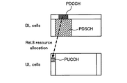
上りリンクで送信される信号は、図1に示すように、適切な無線リソースにマッピングされてユーザ端末(UE(User Equipment)#1,UE#2)から無線基地局に送信される。この場合、ユーザデータは、上り共有チャネル(PUSCH:Physical Uplink Shared Channel)に割り当てられる。また、制御情報は、ユーザデータと同時に送信する場合にはPUSCHと多重され、制御情報のみを送信する場合には上り制御チャネル(PUCCH:Physical Uplink Control Channel)に割り当てられる。 As shown in FIG. 1, signals transmitted on the uplink are mapped to appropriate radio resources and transmitted from user terminals (UE (User Equipment) # 1, UE # 2) to the radio base station. In this case, user data is assigned to an uplink shared channel (PUSCH). Control information is multiplexed with PUSCH when transmitted simultaneously with user data, and assigned to an uplink control channel (PUCCH) when only control information is transmitted.
上りリンクで送信される制御情報には、下りリンクの品質情報(CQI:Channel Quality Indicator)や、下り共有チャネル(PDSCH:Physical Downlink Shared Channel)信号に対する送達確認信号(ACK/NACK)等が含まれる。 The control information transmitted in the uplink includes downlink quality information (CQI: Channel Quality Indicator), an acknowledgment signal (ACK / NACK) for a downlink shared channel (PDSCH) signal, and the like. .
ところで、第3世代のシステム(W−CMDA)は、概して5MHzの固定帯域を用いて、下り回線で最大2Mbps程度の伝送レートを実現できる。一方、LTEのシステムでは、1.4MHz〜20MHzの可変帯域を用いて、下り回線で最大300Mbps及び上り回線で75Mbps程度の伝送レートを実現できる。また、UMTSネットワークにおいては、更なる周波数利用効率及びピークデータレートの向上などを目的として、LTEの後継のシステムも検討されている(例えば、「LTEアドバンスト」又は「LTEエンハンスメント」と呼ぶこともある(以下、「LTE−A」という))。 By the way, the third generation system (W-CMDA) can realize a transmission rate of about 2 Mbps at the maximum in the downlink using a fixed band of 5 MHz in general. On the other hand, in the LTE system, a transmission rate of about 300 Mbps at the maximum in the downlink and about 75 Mbps in the uplink can be realized using a variable band of 1.4 MHz to 20 MHz. In addition, in the UMTS network, a successor system of LTE is also being studied for the purpose of further improving the frequency utilization efficiency and the peak data rate (for example, sometimes referred to as “LTE advanced” or “LTE enhancement”). (Hereinafter referred to as “LTE-A”).
さらに、LTE−Aシステムでは、半径数キロメートル程度の広いカバレッジを有するマクロセル内に、半径数十メートル程度の局所的なカバレッジ有するスモールセル(例えば、ピコセル、フェムトセル、RRH等)が形成されるHetNet(Heterogeneous Network)が検討されている(例えば、非特許文献2)。HetNetは、マクロセルとスモールセルとの少なくとも一部が地理的に重複して配置される無線通信システムである。 Further, in the LTE-A system, a small cell (for example, a pico cell, a femto cell, an RRH, etc.) having a local coverage of a radius of several tens of meters is formed in a macro cell having a wide coverage of a radius of several kilometers. (Heterogeneous Network) has been studied (for example, Non-Patent Document 2). HetNet is a wireless communication system in which at least a part of a macro cell and a small cell are geographically overlapped.
LTE−Aシステムでは、周波数帯域が異なる複数の基本周波数ブロック(コンポーネントキャリア(CC:Component Carrier))を集約して広帯域化するキャリアアグリゲーション(CA:Carrier Aggregation)が検討されている。LTE−Aシステムでは、LTEシステムとの後方互換性(Backward compatibility)を保ちながら広帯域化を図るために、単一の基本周波数ブロックをLTEシステムで使用可能な周波数帯域(例えば、20MHz)とすることが合意されている。 In the LTE-A system, carrier aggregation (CA: Carrier Aggregation) in which a plurality of basic frequency blocks (component carriers (CC: Component Carrier)) having different frequency bands are aggregated to increase the bandwidth has been studied. In the LTE-A system, in order to increase the bandwidth while maintaining backward compatibility with the LTE system, a single basic frequency block is set to a frequency band (for example, 20 MHz) that can be used in the LTE system. Has been agreed.
また、LTE−Aシステムの上りリンクにおいては、無線アクセス方式としてSC−FDMAの適用が検討されている。このため、複数の下りCCで送信された下りリンク信号に対するフィードバック制御情報(CQI、ACK/NACK等)について、上りシングルキャリア送信の特性を維持するために単一のCCから送信することが検討されている。 In addition, in the uplink of the LTE-A system, application of SC-FDMA as a radio access scheme is being studied. For this reason, it is considered to transmit feedback control information (CQI, ACK / NACK, etc.) for downlink signals transmitted by a plurality of downlink CCs from a single CC in order to maintain the characteristics of uplink single carrier transmission. ing.
この場合、複数の下りCCの下りリンク信号に対するフィードバック制御情報は、単純にはCC数倍に増大するため、CAを利用するCCの増加に応じて単一のCCからビット数が大きいフィードバック制御情報を送信する必要がある。そのため、CC数(セル数)に応じて適用する上り制御チャネルフォーマット(PUCCHフォーマット)を選択することにより、フィードバック制御情報の送信を適切に行うことが検討されている。 In this case, since the feedback control information for the downlink signals of a plurality of downlink CCs simply increases by a factor of the number of CCs, the feedback control information having a large number of bits from a single CC as the number of CCs using CA increases. Need to send. Therefore, it has been studied to appropriately transmit feedback control information by selecting an uplink control channel format (PUCCH format) to be applied according to the number of CCs (number of cells).
一方で、HetNetにおいてマクロセルとスモールセル間でCAを行う場合、上述したように、フィードバック制御情報を単一のセル(例えば、マクロセル)の上りCCから選択的に送信することが考えられる。この場合、例えば、各セルの下りCCで送信されるPDSCH信号に対する送達確認信号をマクロセルの上りCCを介してフィードバックすると、マクロセル内のスモールセル数、および下りCC数に応じてマクロセルの上りCCに配置するPUCCHリソースが増大してしまう。 On the other hand, when CA is performed between a macro cell and a small cell in HetNet, as described above, it is conceivable to selectively transmit feedback control information from an uplink CC of a single cell (for example, a macro cell). In this case, for example, when an acknowledgment signal for the PDSCH signal transmitted in the downlink CC of each cell is fed back via the uplink CC of the macro cell, the uplink CC of the macro cell is changed according to the number of small cells in the macro cell and the number of downlink CCs. The PUCCH resource to arrange increases.
本発明はかかる点に鑑みてなされたものであり、HetNetにおいてキャリアアグリゲーションを利用する場合であっても、上りリンク伝送におけるフィードバック制御情報を適切に制御することができるユーザ端末、無線基地局及び無線通信方法を提供することを目的とする。 The present invention has been made in view of such a point, and even when using carrier aggregation in HetNet, a user terminal, a radio base station, and a radio that can appropriately control feedback control information in uplink transmission An object is to provide a communication method.
本発明の一態様に係るユーザ端末は、プライマリセルとセカンダリセルのコンポーネントキャリアをそれぞれ用いて下り共有チャネル信号を受信する受信部と、受信した下り共有チャネル信号に対する送達確認信号を生成する生成部と、前記送達確認信号を所定の上り制御チャネルリソースで送信する送信部と、を有し、前記送信部は、前記送達確認信号の内容及び/又は上り制御チャネルフォーマットに基づいて、プライマリセルとセカンダリセルの上り制御チャネルリソースの一方又は双方で前記送達確認信号を送信することを特徴とする。 User terminal according to an embodiment of the present invention includes a receiver for receiving a downlink shared channel signal using each component carrier flop Raimariseru and secondary cell, a generator for generating an acknowledgment signal for the downlink shared channel signal received A transmission unit that transmits the delivery confirmation signal using a predetermined uplink control channel resource , and the transmission unit uses a primary cell and a secondary cell based on the content of the delivery confirmation signal and / or the uplink control channel format. characterized by at one or both of the uplink control channel resource transmitting the acknowledgment signal.
本発明によれば、HetNetにおいてキャリアアグリゲーションを利用する場合であっても、上りリンク伝送におけるフィードバック制御情報を適切に制御することができる。 According to the present invention, even when carrier aggregation is used in HetNet, feedback control information in uplink transmission can be appropriately controlled.
ユーザ端末は、下り共有チャネル(PDSCH)信号に対する送達確認信号(ACK/NACK)を、上り制御チャネル(PUCCH)を用いて送信することができる。送達確認信号(再送応答信号)は、送信信号が適切に受信されたことを示す肯定応答(ACK:Acknowledgement)又はそれが適切に受信されなかったことを示す否定応答(NACK:Negative Acknowledgement)で表現される。 The user terminal can transmit an acknowledgment signal (ACK / NACK) for the downlink shared channel (PDSCH) signal using the uplink control channel (PUCCH). The acknowledgment signal (retransmission response signal) is expressed by an acknowledgment (ACK: Acknowledgement) indicating that the transmission signal has been properly received or a negative acknowledgment (NACK: Negative Acknowledgement) indicating that it has not been properly received. Is done.
無線基地局は、ACKによりPDSCH信号の送信成功を判断し、NACKによりPDSCH信号に誤りが検出されたことを判断する。また、無線基地局は、上りリンクにおいて送達確認信号に割当てられた無線リソースの受信電力が所定値以下である場合にDTX(Discontinuous Transmission)であると判定することができる。DTXは、「ACKもNACKもユーザ端末から通知されなかった」という判定結果であり、例えば、これはユーザ端末が下り制御チャネル(PDCCH)信号を受信できなかったことを意味する。 The radio base station determines successful transmission of the PDSCH signal based on ACK, and determines that an error has been detected in the PDSCH signal based on NACK. Also, the radio base station can determine that the received power of the radio resource allocated to the delivery confirmation signal in the uplink is equal to or less than a predetermined value as DTX (Discontinuous Transmission). The DTX is a determination result that “ACK and NACK were not notified from the user terminal”. For example, this means that the user terminal could not receive the downlink control channel (PDCCH) signal.
また、ユーザ端末は、送達確認信号を割当てるPUCCHリソースとして、上位レイヤシグナリング(例えば、RRCシグナリング)で設定されるパタメータと、PDCCHの制御チャネル要素(CCE:Control Channel Element)番号(CCEインデックス)、拡張PDCCH(E−PDCCH)の拡張CCE(ECCE)番号(ECCEインデックス)から決定することができる(図2参照)。PUCCHリソースとしては、例えば、OCC(Orthogonal Cover Code)、CS(Cyclic Shift)、RB(Resource Block)インデックス等を利用することができる。ユーザ端末は、所定のPUCCHリソースに送達確認信号を多重して無線基地局にフィードバックする。 In addition, as a PUCCH resource to which a delivery confirmation signal is assigned, a user terminal sets parameters set by higher layer signaling (for example, RRC signaling), a PDCCH control channel element (CCE) number (CCE index), an extension It can be determined from the extended CCE (ECCE) number (ECCE index) of PDCCH (E-PDCCH) (see FIG. 2). As the PUCCH resource, for example, an OCC (Orthogonal Cover Code), a CS (Cyclic Shift), an RB (Resource Block) index, or the like can be used. The user terminal multiplexes a delivery confirmation signal with a predetermined PUCCH resource and feeds back to the radio base station.
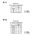
また、LTE(Rel.8)では、下り共有チャネル(PDSCH)信号に対する送達確認信号の通知フォーマット(PUCCH format 1a/1b)が規定されている(図3参照)。
In LTE (Rel. 8), a notification format (
1コードワード(1CW)伝送(1トランスポートブロック数(1TB))の場合は、“ACK”、“NACK”、“DTX”の3状態が規定され(図3A参照)、2コードワード(2CW)伝送(2トランスポートブロック数(2TB))の場合は“ACK、ACK”、“ACK、NACK”、“NACK、ACK”、“NACK、NACK”、“DTX”の5状態が規定されている(図3B参照)。なお、以下の説明において、“ACK”を“A”、“NACK”を“N”、“DTX”を“D”とも表記する。 In the case of 1 codeword (1CW) transmission (1 transport block number (1TB)), three states of “ACK”, “NACK”, and “DTX” are defined (see FIG. 3A), and 2 codewords (2CW) In the case of transmission (2 transport blocks (2 TB)), five states of “ACK, ACK”, “ACK, NACK”, “NACK, ACK”, “NACK, NACK”, and “DTX” are defined ( (See FIG. 3B). In the following description, “ACK” is also expressed as “A”, “NACK” as “N”, and “DTX” as “D”.
図3のマッピングテーブルにおいて、“0”は当該サブフレームで、ユーザ端末が無線基地局に対して情報を送信しないことを示し、“1”、“−1”、“j”、“−j”はそれぞれ特定の位相状態を表している。例えば、図3Aにおいて、“1”、“−1”はそれぞれ「0」、「1」に相当し、1ビットの情報を表すことができる。また、図3Bにおいて、“1”、“−1”、“j”、“−j”は、それぞれ「00」、「11」、「10」、「01」のデータに相当し、2ビットの情報を表すことができる。したがって、PUCCH format 1a/1bにおいては、最大2ビットまでの送達確認信号の送信が可能となっている。
In the mapping table of FIG. 3, “0” indicates that the user terminal does not transmit information to the radio base station in the subframe, and “1”, “−1”, “j”, “−j”. Each represents a specific phase state. For example, in FIG. 3A, “1” and “−1” correspond to “0” and “1”, respectively, and can represent 1-bit information. In FIG. 3B, “1”, “−1”, “j”, and “−j” correspond to “00”, “11”, “10”, and “01” data, respectively. Information can be represented. Therefore, in the
一方、LTE−Aシステムにおいては、上りシングルキャリア送信の特性を維持するために、複数の下りCCで送信されたPDSCH信号に対する送達確認信号を特定のCC(プライマリセル)のPUCCHを用いてフィードバックすることが検討されている。さらに、LTE−Aシステムでは、PUCCH format 1a/1bと複数のPUCCHリソース(位相状態の情報とPUCCHリソースの位置情報)を用いて、送達確認信号をフィードバックすることが検討されている(チャネルセレクション(channel selection)、またはPUCCH format 1a/1b with channel selection)。チャネルセレクションにおいては、複数CCの送達確認信号の組み合わせを、位相状態の情報とPUCCHリソースの位置情報で規定するマッピングテーブルが合意されている。
On the other hand, in the LTE-A system, in order to maintain the characteristics of uplink single carrier transmission, an acknowledgment signal for a PDSCH signal transmitted in a plurality of downlink CCs is fed back using a PUCCH of a specific CC (primary cell). It is being considered. Furthermore, in the LTE-A system, feedback of a delivery confirmation signal using
<チャネルセレクション>
現在、LTE−AシステムのFDD方式においては、2CCのとき、チャネルセレクションを用いることが合意されている。図4に、キャリアアグリゲーションを2CC(プライマリセル(PCell)及びセカンダリセル(SCell))で行う場合に、チャネルセレクションで利用するマッピングテーブルの一例を示す。マッピングテーブルはACK/NACKビット数によって異なり、このビット数は上位レイヤシグナリング(例えば、RRCシグナリング)により設定されるCC数及び送信モード(TB数、又はCW数等)に基づいて決定される。
<Channel selection>
At present, in the FDD scheme of the LTE-A system, it has been agreed to use channel selection for 2CC. FIG. 4 shows an example of a mapping table used in channel selection when carrier aggregation is performed in 2CC (primary cell (PCell) and secondary cell (SCell)). The mapping table differs depending on the number of ACK / NACK bits, and this number of bits is determined based on the number of CCs and the transmission mode (TB number, CW number, etc.) set by higher layer signaling (for example, RRC signaling).
図4Aは、PUCCH format 1bに対して2つのPUCCHリソース(Ch1及びCh2)を設定する場合(PCell及びSCellが1CWの場合)を示している。図4Bは、PUCCH format 1bに対して3つのPUCCHリソース(Ch1〜Ch3)を設定する場合(PCell及びSCellの一方が1CW、他方が2CWの場合)を示している。図4Cは、PUCCH format 1bに対して4つのPUCCHリソース(Ch1〜Ch4)を設定する場合(PCell及びSCellが2CWの場合)を示している。
FIG. 4A shows a case where two PUCCH resources (Ch1 and Ch2) are set for
マッピングテーブルにおける無線リソース(例えば、Ch1〜Ch4)としては、LTEシステムと同様に、OCC(Orthogonal Cover Code)、CS(Cyclic Shift)、RB(Resource Block)インデックス等を用いることができる。 As a radio resource (for example, Ch1 to Ch4) in the mapping table, OCC (Orthogonal Cover Code), CS (Cyclic Shift), RB (Resource Block) index, and the like can be used as in the LTE system.
ユーザ端末は、CC毎のPDSCH信号に対する送達確認信号(ACK/NACK)の組み合わせと、図4に示したマッピングテーブルとに基づいて、送達確認信号の送信に利用するPUCCHリソース(Ch1〜Ch4のいずれか)を決定する。例えば、PCell及びSCellがそれぞれ2CWの場合に、PCellのPUSCH信号に対する送達確認信号として“NACK,ACK”、SCellのPUSCH信号に対する送達確認信号として“ACK,ACK”をフィードバックする際には、PUCCHリソース(Ch2)におけるQPSK変調シンボルの“−j”を用いる(図4C参照)。 Based on the combination of the acknowledgment signal (ACK / NACK) for the PDSCH signal for each CC and the mapping table shown in FIG. 4, the user terminal uses any of the PUCCH resources (Ch1 to Ch4) used for transmission of the acknowledgment signal. Or). For example, when PCell and SCell are each 2CW, when “NACK, ACK” is fed back as a delivery confirmation signal for the PCell PUSCH signal and “ACK, ACK” is fed back as a delivery confirmation signal for the SCell PUSCH signal, the PUCCH resource “−j” of the QPSK modulation symbol in (Ch2) is used (see FIG. 4C).
チャネルセレクションにおけるPUCCHのリソースとして、例えば、図4Cに示すマッピングテーブルにおいて、PUCCHリソース(例えば、Ch1、Ch2)は、PCellにおけるPDCCHのCCEインデックス(例えば、最も若い番号)を用いて指定することができる。 As a PUCCH resource in channel selection, for example, in the mapping table shown in FIG. 4C, a PUCCH resource (for example, Ch1, Ch2) can be specified using a PCECH CCE index (for example, the youngest number) in the PCell. .
また、他のPUCCHリソース(例えば、Ch3、Ch4)は、上位レイヤシグナリング(例えば、RRCシグナリング)と下り制御情報(DCI)とを用いて指定することができる(図5参照)。具体的には、上りリンクPCellに対して、1又は2つのPUCCHリソース(例えば、Ch3、Ch4)からなるセットを4セットだけ上位レイヤシグナリングでユーザ端末に通知する。そして、SCellのPDSCHをスケジューリングする下り制御情報に含まれるARI(ACK/NACK Resource Indicator)を用いて複数のPUCCHリソースの中から所定のPUCCHリソースをダイナミックに指定することができる。 Also, other PUCCH resources (for example, Ch3 and Ch4) can be specified using higher layer signaling (for example, RRC signaling) and downlink control information (DCI) (see FIG. 5). Specifically, only four sets of one or two PUCCH resources (for example, Ch3 and Ch4) are notified to the uplink PCell by higher layer signaling. Then, a predetermined PUCCH resource can be dynamically specified from among a plurality of PUCCH resources by using an ARI (ACK / NACK Resource Indicator) included in downlink control information for scheduling the PDSCH of the SCell.
ここで、ARIとは、送達確認信号に使用するPUCCHリソースをダイナミックに指定するための識別情報である。例えば、無線基地局は、各ユーザ端末に対してRRCシグナリングにより複数(例えば、4つ)のPUCCHリソースを割当て、当該複数のPUCCHリソースの中から、ARIを用いて所定のPUCCHリソースをダイナミックに指定する。ARIを規定するビットフィールドは、SCellのPDCCHにおけるTPCコマンドフィールド(2ビット)で置換することができる。 Here, the ARI is identification information for dynamically specifying the PUCCH resource used for the delivery confirmation signal. For example, the radio base station allocates a plurality (for example, four) of PUCCH resources to each user terminal by RRC signaling, and dynamically designates a predetermined PUCCH resource using the ARI from among the plurality of PUCCH resources. To do. The bit field that defines the ARI can be replaced with the TPC command field (2 bits) in the SCell's PDCCH.
<PUCCHフォーマット3>
また、LTE−Aにおいては、多数のACK/NACKビットを伝送するためにPUCCHフォーマット3が新たに規定されている。PUCCHフォーマット3では、PDSCHと同様に、信号がDFT(Discrete Fourier Transform)ベースのプリコーディングにより生成され、直交符号(OCC:Orthogonal Cover Code)により異なるUEを多重することができる(図6参照)。具体的には、複数セルのACK/NACKに対して、チャネル符号化を行い、1サブフレームあたりのビット数を48ビットとして出力する。出力された48ビットの系列に対して位相偏移変調(QPSK)により24シンボルにした後、DFT処理を行う。
<
In LTE-A,
PUCCHフォーマット3を適用することにより、FDDシステムでは最大10個のACK/NACKがサポートされ、TDDシステムでは最大20ビットのACK/NACKがサポートされる。つまり、PUCCHフォーマット3は、CA適用時の複数セル(例えば、FDDでは3Cell以上)のACK/NACKのフィードバック用のフォーマットとして好適に用いられる。
By applying
PUCCHフォーマット3で利用するPUCCHリソースは、無線基地局からユーザ端末に明示的(explicitly)に通知する構成とすることができる。例えば、RRCシグナリングを用いて、上りリンクにおけるPCellに複数のPUCCHリソース(例えば、4つのリソース)を割当て、ユーザ端末に通知する。また、下りリンクにおけるSCellで送信されるPDSCH信号に対応するPDCCH信号において、TPCコマンドフィールド(例えば、2ビット)をARI用のフィールドとして利用する(図7参照)。
The PUCCH resource used in the
つまり、無線基地局は、ARIを利用してRRCシグナリングで通知した複数のPUCCHリソースの中から1つのPUCCHリソースをダイナミックに割当てることができる。なお、ユーザ端末は、ARIを含むSCellのPDCCH信号を1つも受信しない場合には、PCellのPDCCHのCCEインデックスを用いてPUCCHリソースを選択することができる(Rel.8におけるPUCCH format 1a/1bと同じ方法)。
That is, the radio base station can dynamically allocate one PUCCH resource among a plurality of PUCCH resources notified by RRC signaling using ARI. In addition, a user terminal can select a PUCCH resource using the CCE index of PDCCH of PCell, when it does not receive any SCell PDCCH signal including ARI (
このように、CAにおけるセル数(ACK/NACKのビット数)に応じてPUCCHフォーマット(PUCCHフォーマット1a/1b、チャネルセレクション、PUCCHフォーマット3等)を選択して利用することにより、複数CCの送達確認信号のフィードバックを適切に行うことができる。
As described above, by selecting and using the PUCCH format (
<HetNet CA>
ところで、Rel.12以降では、HetNetにおけるキャリアアグリゲーションが検討されており、この場合の送達確認信号のPUCCH無線リソースの割当てが問題となる。以下に、HetNetでCAを適用する場合のPUCCHリソース割当てについて説明する。
<HetNet CA>
By the way, Rel. From 12 onward, carrier aggregation in HetNet has been studied, and allocation of PUCCH radio resources for delivery confirmation signals in this case becomes a problem. Hereinafter, PUCCH resource allocation when CA is applied in HetNet will be described.
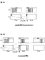
図8Bは、HetNetの概念図である。図8Bに示すように、HetNetは、マクロセルと地理的に重畳するように多数のスモールセルが配置される無線通信システムである。ここでは、マクロセルを形成する無線基地局(以下、マクロ基地局という)、各スモールセルを形成する無線基地局(スモール基地局)、マクロ基地局及びスモール基地局の少なくとも一つと通信を行うユーザ端末を含む。 FIG. 8B is a conceptual diagram of HetNet. As shown in FIG. 8B, HetNet is a wireless communication system in which a large number of small cells are arranged so as to overlap geographically with a macro cell. Here, a radio base station that forms a macro cell (hereinafter referred to as a macro base station), a radio base station that forms each small cell (small base station), a user terminal that communicates with at least one of the macro base station and the small base station including.
図8に示すように、マクロセルでは、例えば、800MHzや2GHzなど、相対的に周波数帯が低いキャリアF1を用い、多数のスモールセルSでは、例えば、3.5GHzなど、相対的に周波数帯が高いキャリアF2を用いる構成とすることができる。なお、マクロ基地局は、eNodeB(eNB)、マクロeNB(MeNB)、送信ポイント等と称されても良い。また、スモール基地局は、ピコeNB、フェムトeNB、RRH(Remote Radio Head)、送信ポイント等と称されてもよい。また、マクロ基地局と各スモール基地局とは、例えば、光ファイバー、X2インターフェース又は無線リンクを介して接続された構成とすることができる。 As shown in FIG. 8, in the macro cell, for example, a carrier F1 having a relatively low frequency band such as 800 MHz or 2 GHz is used, and in a large number of small cells S, for example, the frequency band is relatively high such as 3.5 GHz. It can be set as the structure which uses the carrier F2. In addition, a macro base station may be called eNodeB (eNB), macro eNB (MeNB), a transmission point, etc. The small base station may be referred to as a pico eNB, a femto eNB, an RRH (Remote Radio Head), a transmission point, or the like. The macro base station and each small base station can be configured to be connected via, for example, an optical fiber, an X2 interface, or a wireless link.
ただし、Rel.11までの検討では、基地局内キャリアアグリゲーション(Intra−eNB CA)のみがサポートされており、このような構成において、マクロ基地局とスモール基地局は、例えば、光ファイバーを介してCAを適用する。この場合、上述したように、送達確認信号をプライマリセル(例えば、マクロセル)の上りCCのPUCCHに集約してフィードバックする。 However, Rel. In the examination up to 11, only intra-base station carrier aggregation (Intra-eNB CA) is supported, and in such a configuration, the macro base station and the small base station apply CA via, for example, an optical fiber. In this case, as described above, the delivery confirmation signal is aggregated and fed back to the PUCCH of the uplink CC of the primary cell (for example, the macro cell).
しかしながら、図8Bに示すように、マクロセルのカバレッジエリア内に複数のスモールセル(RRH)が存在する構成では、マクロセル(PCell)と、同一CCを用いる複数のスモールセル(RRH#1(SCell#1)、RRH#2(SCell#2))の送達確認信号をマクロセルの上りPUCCHリソースに割当てることとなる。この場合、スモールセル数の増加に伴いSCellの数が増加するため、送達確認信号の割当てに必要となるPCellのPUCCHリソースが増大してしまう(図8A参照)。 However, as shown in FIG. 8B, in a configuration in which a plurality of small cells (RRH) are present in the coverage area of the macro cell, the macro cell (PCell) and a plurality of small cells (RRH # 1 (SCell # 1) using the same CC are used. ), RRH # 2 (SCell # 2)) acknowledgment signal is assigned to the uplink PUCCH resource of the macro cell. In this case, since the number of SCells increases as the number of small cells increases, the PUC PUCCH resources necessary for allocation of the delivery confirmation signal increase (see FIG. 8A).
そこで、本発明者らは、HetNetのCAにおいて、送達確認信号を割当てるPUCCHリソースとして、PCellに加えてSCellにPUCCHリソースを配置することにより、PCellにおけるPUCCHリソースの増大を抑制することを見出した。 Therefore, the present inventors have found that, in the HetNet CA, as a PUCCH resource to which an acknowledgment signal is assigned, the PUCCH resource is arranged in the SCell in addition to the PCell, thereby suppressing an increase in the PUCCH resource in the PCell.
具体的には、送達確認信号の割当てを行うPUCCHリソースの候補としてPCellだけでなくSCellも考慮して、送達確認信号の内容及び/又は利用する上り制御チャネルフォーマット等に応じて、ユーザ端末がプライマリセルとセカンダリセルのPUCCHリソースの一方又は双方に送達確認信号の割当てを行う。 Specifically, considering not only the PCell but also the SCell as a PUCCH resource candidate for allocating a delivery confirmation signal, the user terminal is primary depending on the contents of the delivery confirmation signal and / or the uplink control channel format to be used. An acknowledgment signal is assigned to one or both of the PUCCH resources of the cell and the secondary cell.
以下に、本実施の形態について図面を参照して具体的に説明する。なお、以下の説明では、HetNetのキャリアアグリゲーションの形態として、基地局内キャリアアグリゲーション(Intra−eNB CA)と、基地局間キャリアアグリゲーション(Inter−eNB CA)の場合についてそれぞれ説明する。 The present embodiment will be specifically described below with reference to the drawings. In the following description, cases of intra-base station carrier aggregation (Intra-eNB CA) and inter-base station carrier aggregation (Inter-eNB CA) will be described as forms of HetNet carrier aggregation.
<Intra−eNB CA>
基地局内キャリアアグリゲーション(Intra−eNB CA)は、マクロ基地局だけに通信制御部(例えば、BB(ベースバンド)処理部やスケジューリング部など)が設けられるHetNet構成で行われる。かかるHetNet構成では、マクロ基地局とスモール基地局とが光ファイバーで接続される。また、マクロ基地局が、マクロセルにおける低周波数帯キャリアF1を用いた通信とスモールセルにおける高周波数帯キャリアF2を用いた通信との双方を制御する。
<Intra-eNB CA>
Intra-base station carrier aggregation (Intra-eNB CA) is performed in a HetNet configuration in which only a macro base station is provided with a communication control unit (for example, a BB (baseband) processing unit or a scheduling unit). In such a HetNet configuration, the macro base station and the small base station are connected by an optical fiber. Further, the macro base station controls both the communication using the low frequency band carrier F1 in the macro cell and the communication using the high frequency band carrier F2 in the small cell.
基地局内CAにおいて、従来はプライマリセル(例えば、マクロセル)におけるCC及びセカンダリセル(例えば、スモールセル)におけるCCで送信されるPDSCH信号に対する送達確認信号を、プライマリセルのPUCCHリソースに集約して割当てる構成となっていた。 In the intra-base station CA, a configuration in which a delivery confirmation signal for a PDSCH signal transmitted in a CC in a primary cell (for example, a macro cell) and a CC in a secondary cell (for example, a small cell) is collectively allocated to the PUCCH resource of the primary cell. It was.
本実施の形態では、HetNetで基地局内CAを行う場合に、SCellにもPUCCHリソースを配置し、ユーザ端末が送達確認信号の割当てを行うPUCCHリソースとして、プライマリセルのPUCCHリソースとセカンダリセルのPUCCHリソースを利用する。また、ユーザ端末は、送達確認信号の内容及び/又は適用する上り制御チャネルフォーマット等に基づいて、プライマリセルとセカンダリセルのいずれか一方のPUCCHリソースを選択して、送達確認信号の割当てを行う。以下に、基地局内CAにおけるPUCCHリソースの割当て方法として、2Cellの場合と3Cell以上の場合についてそれぞれ具体的に説明する。 In the present embodiment, when performing intra-base station CA with HetNet, PUCCH resources are also allocated to SCells, and PUCCH resources for user terminals to allocate acknowledgment signals are used as primary cell PUCCH resources and secondary cell PUCCH resources. Is used. Also, the user terminal selects a PUCCH resource of either the primary cell or the secondary cell based on the content of the delivery confirmation signal and / or the applied uplink control channel format, etc., and assigns the delivery confirmation signal. Hereinafter, the case of 2 cells and the case of 3 cells or more will be specifically described as PUCCH resource allocation methods in the CA in the base station.
(2Cellの場合)
2Cellで基地局内CAを行う場合、送達確認信号の割当てを行うPUCCHリソースとして、Rel.10におけるチャネルセレクションを利用(リユース)して設定することができる。本実施の形態では、Rel.10のチャネルセレクションにおいてRRCシグナリングにより設定されるプライマリセルのPUCCHリソースに変えて、セカンダリセルのPUCCHリソースを用いる(図9A参照)。
(In the case of 2Cell)
When performing intra-base station CA with 2 cells, Rel. 10 can be used (reused) for channel selection. In the present embodiment, Rel. In the ten channel selection, the PUCCH resource of the secondary cell is used instead of the PUCCH resource of the primary cell set by RRC signaling (see FIG. 9A).
例えば、上記図4Bに示すように3つのPUCCHリソース(Ch1〜Ch3)を設定する場合、Ch1及びCh2はRel.10と同様にプライマリセルにおけるPDCCHのCCEインデックスに基づいて設定する(プライマリセルが2CWの場合)。一方で、Ch3については、プライマリセルのPUCCHリソース(RRCシグナリングで通知)でなく、セカンダリセルのPDSCHに対応するPDCCHのCCEインデックスに基づいて、セカンダリセルのPUCCHリソースを設定する。 For example, when three PUCCH resources (Ch1 to Ch3) are set as shown in FIG. 4B above, Ch1 and Ch2 are Rel. 10 is set based on the CCE index of the PDCCH in the primary cell (when the primary cell is 2CW). On the other hand, for Ch3, the PUCCH resource of the secondary cell is set based on the CCE index of the PDCCH corresponding to the PDSCH of the secondary cell, not the PUCCH resource of the primary cell (notified by RRC signaling).
また、上記図4Cに示すように4つのPUCCHリソース(Ch1〜Ch4)を設定する場合、Ch1及びCh2はRel.10と同様にプライマリセルにおけるPDCCHのCCEインデックスに基づいて設定する。一方で、Ch3、Ch4については、プライマリセルのPUCCHリソース(RRCシグナリングで通知)でなく、セカンダリセルのPDSCHに対応するPDCCHのCCEインデックスに基づいて、セカンダリセルのPUCCHリソースを設定する。 Also, as shown in FIG. 4C, when four PUCCH resources (Ch1 to Ch4) are set, Ch1 and Ch2 are Rel. 10 is set based on the PDCCH CCE index in the primary cell. On the other hand, for Ch3 and Ch4, the PUCCH resource of the secondary cell is set based on the CCE index of the PDCCH corresponding to the PDSCH of the secondary cell, not the PUCCH resource of the primary cell (notified by RRC signaling).
つまり、チャネルセレクションにおいて、送達確認信号の割当て候補となる複数のPUCCHリソースとして、PCellのPUCCHリソース(Ch1、Ch2)とSCellのPUCCHリソース(Ch3、Ch4)を設定する。ユーザ端末は、各セル(CC)のCWの送達確認信号の内容に基づいて、マッピングテーブルを参照して複数のPUCCHリソース(Ch1〜Ch4)の中から所定PUCCHリソースを選択する。そして、選択したPUCCHリソースに送達確認信号をマッピングして、無線基地局(例えば、マクロ基地局)にフィードバックする。 That is, in the channel selection, the PCell PUCCH resources (Ch1, Ch2) and the SCell PUCCH resources (Ch3, Ch4) are set as a plurality of PUCCH resources that are candidates for delivery confirmation signal allocation. The user terminal selects a predetermined PUCCH resource from a plurality of PUCCH resources (Ch1 to Ch4) with reference to the mapping table based on the content of the CW delivery confirmation signal of each cell (CC). Then, a delivery confirmation signal is mapped to the selected PUCCH resource and fed back to a radio base station (for example, a macro base station).
なお、ユーザ端末は、プライマリセルからのみPDCCHを受信する場合(例えば、あるサブフレームにおいてセカンダリセルのPDCCHを受信しない場合)、プライマリセルのPDCCHのCCEインデックスを用いて、プライマリセルのPUCCHリソースを選択する。この場合、無線基地局(例えば、マクロ基地局)は、プライマリセルにおけるPUCCHリソース候補(例えば、Ch1、2)に基づいて送達確認信号を検出し、再送制御処理を行うことが可能となる。
When the user terminal receives PDCCH only from the primary cell (for example, when not receiving the PDCCH of the secondary cell in a certain subframe), the user terminal selects the PUCCH resource of the primary cell using the CCE index of the PDCCH of the primary cell. To do. In this case, a radio base station (for example, a macro base station) can detect a delivery confirmation signal based on PUCCH resource candidates (for example,
また、ユーザ端末は、セカンダリセルからのみPDCCHを受信する場合(例えば、あるサブフレームにおいてプライマリセルのPDCCHを受信しない場合)、セカンダリセルのPDCCHのCCEインデックスを用いて、セカンダリセルのPUCCHリソースを選択する。この場合、無線基地局(例えば、マクロ基地局)は、セカンダリセルにおけるPUCCHリソース候補(例えば、Ch3、4)に基づいて送達確認信号を検出し、再送制御処理を行うことが可能となる。 Also, when the user terminal receives PDCCH only from the secondary cell (for example, when not receiving PDCCH of the primary cell in a certain subframe), the user terminal selects the PUCCH resource of the secondary cell using the CCE index of the PDCCH of the secondary cell. To do. In this case, a radio base station (for example, a macro base station) can detect a delivery confirmation signal based on PUCCH resource candidates (for example, Ch3 and 4) in the secondary cell, and can perform a retransmission control process.
また、ユーザ端末は、プライマリセル及びセカンダリセルの双方からPDCCHを受信する場合、送達確認信号の内容に応じてプライマリセル又はセカンダリセルの所定のPUCCHリソースを選択する。この場合、無線基地局(例えば、マクロ基地局)は、プライマリセルとセカンダリセルにおけるPUCCHリソース候補(Ch1〜4)に基づいて送達確認信号を検出し、再送制御処理を行うことが可能となる。 Moreover, a user terminal selects the predetermined PUCCH resource of a primary cell or a secondary cell according to the content of the delivery confirmation signal, when receiving PDCCH from both a primary cell and a secondary cell. In this case, a radio base station (for example, a macro base station) can detect a delivery confirmation signal based on PUCCH resource candidates (Ch1 to Ch4) in the primary cell and the secondary cell, and perform a retransmission control process.
なお、プライマリセルのPUCCHリソース(Ch1、Ch2)はRel.10と同様にプライマリセルのPDCCHのCCEインデックスに基づいて決定することができる。また、セカンダリセルのPUCCHリソース(Ch3、Ch4)はRel.10のプライマリセルと同様にセカンダリセルのPDCCHのインデックスに基づいて決定することができる。 Note that the PUCCH resources (Ch1, Ch2) of the primary cell are Rel. 10 can be determined based on the CCE index of the PDCCH of the primary cell. Further, the PUCCH resources (Ch3, Ch4) of the secondary cell are Rel. Similarly to the 10 primary cells, it can be determined based on the PDCCH index of the secondary cell.
このように、2Cellで基地局内CAを行う場合、各セル(CC)の送達確認信号はプライマリセル又はセカンダリセルのPUCCHのいずれか一方に集約されてフィードバックされる。このように、セカンダリセルにおけるPUCCHリソースを用いる場合でも、チャネルセレクションのマッピングテーブルを用いることで、プライマリセルとセカンダリセルの上りリンクにおいて同時送信を避けることができる(図9A参照)。さらに、Rel.10のチャネルセレクションと比較して、RRCシグナリングにより設定されるプライマリセルのPUCCHリソースを不要とすることができる。 Thus, when performing intra-base station CA with 2 cells, the delivery confirmation signal of each cell (CC) is aggregated and fed back to either the primary cell or the secondary cell PUCCH. Thus, even when using the PUCCH resource in the secondary cell, simultaneous transmission in the uplink of the primary cell and the secondary cell can be avoided by using the channel selection mapping table (see FIG. 9A). Furthermore, Rel. Compared with ten channel selections, the PUCCH resource of the primary cell set by RRC signaling can be made unnecessary.
このように、送達確認信号の割当て候補となる複数のPUCCHリソースとして、PCellとSCellのPUCCHリソースを利用することにより、HetNetでセル内CAを行う場合であっても、送達確認信号の割当てに必要となるPCellのPUCCHリソースの増大を抑制することが可能となる。 In this way, by using the PUCCH resources of the PCell and SCell as a plurality of PUCCH resources that are candidates for delivery confirmation signal allocation, it is necessary for allocation of delivery confirmation signals even when performing intra-cell CA with HetNet. It is possible to suppress an increase in the PUCCH resource of the PCell.
(3Cell以上の場合)
3Cell以上で基地局内CAを行う場合、送達確認信号の割当てを行うPUCCHリソースとして、既に規定されているPUCCHフォーマット3を利用(リユース)することができる。本実施の形態では、Rel.10のPUCCHフォーマット3においてRRCシグナリングにより設定されるプライマリセルのPUCCHリソースに変えて、セカンダリセルのPUCCHリソースを用いる(図9B参照)。
(In case of 3 cells or more)
When performing intra-base station CA with 3 cells or more,
例えば、無線基地局は、上位レイヤシグナリング(例えば、RRCシグナリング)を用いて、各ユーザ端末の上りリンクのSCellに複数のリソース(例えば、4つのリソース)を設定して、ユーザ端末に通知する。また、無線基地局は、ARIを利用して、上位レイヤシグナリングで設定した複数のSCellのPUCCHリソースから1つのPUCCHリソースをダイナミックに割当てることができる。なお、無線基地局は、ARIをSCellのPDCCHに含めてユーザ端末に通知することができる。 For example, the radio base station sets a plurality of resources (for example, four resources) in the uplink SCell of each user terminal using higher layer signaling (for example, RRC signaling), and notifies the user terminal. Further, the radio base station can dynamically allocate one PUCCH resource from PUCCH resources of a plurality of SCells set by higher layer signaling using ARI. The radio base station can notify the user terminal by including the ARI in the SCell's PDCCH.
また、ユーザ端末は、ARIを含むSCellのPDCCHを1つも受信しない場合(例えば、あるサブフレームにおいてプライマリセルからのみPDCCHを受信する場合)、PCellのPDCCHのCCEインデックスを用いてPUCCHリソースを選択する(PUCCHフォーマット1a/1bを利用する)ことができる。この場合、無線基地局(例えば、マクロ基地局)は、プライマリセルのPDCCHのCCEインデックスに基づいて設定されるプライマリセルのPUCCHリソースに基づいて送達確認信号を検出し、再送制御処理を行うことが可能となる。
Further, when the user terminal does not receive any PDCCH of the SCell including the ARI (for example, when receiving the PDCCH only from the primary cell in a certain subframe), the user terminal selects the PUCCH resource using the CCE index of the PCell PDCCH. (Utilizing
また、ユーザ端末は、セカンダリセルからのみPDCCHを受信する場合(例えば、あるサブフレームにおいてプライマリセルのPDCCHを受信しない場合)、複数のセカンダリセルのPUCCHリソースの中からARIにより指定される1つのPUCCHリソースを選択する(PUCCHフォーマット3を利用する)。この場合、無線基地局(例えば、マクロ基地局)は、セカンダリセルの所定PUCCHリソースに基づいて送達確認信号を検出し、再送制御処理を行うことが可能となる。 Further, when the user terminal receives the PDCCH only from the secondary cell (for example, when not receiving the PDCCH of the primary cell in a certain subframe), one PUCCH specified by the ARI among the PUCCH resources of the plurality of secondary cells Select a resource (use PUCCH format 3). In this case, a radio base station (for example, a macro base station) can detect a delivery confirmation signal based on a predetermined PUCCH resource of the secondary cell and perform retransmission control processing.
また、ユーザ端末は、プライマリセル及びセカンダリセルからPDCCHを受信する場合、複数のセカンダリセルのPUCCHリソースの中からARIにより指定される1つのPUCCHリソースを選択する(PUCCHフォーマット3を利用する)。この場合、無線基地局(例えば、マクロ基地局)は、プライマリセル、およびセカンダリセルの所定PUCCHリソースに基づいて送達確認信号を検出し、再送制御処理を行うことが可能となる。 Moreover, when receiving a PDCCH from a primary cell and a secondary cell, a user terminal selects one PUCCH resource designated by ARI from among the PUCCH resources of a plurality of secondary cells (using PUCCH format 3). In this case, a radio base station (for example, a macro base station) can detect a delivery confirmation signal based on predetermined PUCCH resources of the primary cell and the secondary cell, and perform a retransmission control process.
このように、3Cell以上で基地局内CAを行う場合、プライマリセルからのみPDCCHを受信する場合はプライマリセルのPUCCHを利用し、それ以外の場合には、各セル(CC)の送達確認信号がセカンダリセルのPUCCHに集約されてフィードバックされる。このため、プライマリセルとセカンダリセルの上りリンクにおいて同時送信を避けることができる(図9B参照)。また、Rel.10のPUCCHフォーマット3と比較して、送達確認信号はセカンダリセルのPUCCHリソースに割当てられる。
Thus, when performing intra-base station CA with 3 cells or more, the PUCCH of the primary cell is used when receiving the PDCCH only from the primary cell, and in other cases, the delivery confirmation signal of each cell (CC) is secondary. It is aggregated and fed back to the PUCCH of the cell. For this reason, simultaneous transmission can be avoided in the uplink of a primary cell and a secondary cell (refer FIG. 9B). Also, Rel. Compared to 10
このように、PUCCHフォーマット3を利用する際に送達確認信号の割当て候補となる複数のPUCCHリソースとして、各SCellのPUCCHリソースを用いることにより、HetNetでセル内CAを行う場合であっても、送達確認信号の割当てに必要となるPCellのPUCCHリソースの増大を抑制することが可能となる。
Thus, even when performing intra-cell CA on HetNet by using the PUCCH resource of each SCell as a plurality of PUCCH resources that are candidates for delivery confirmation signal allocation when using
<Inter−eNB CA>
基地局間キャリアアグリゲーション(Inter−eNB CA)は、マクロ基地局とスモール基地局との双方に通信制御部(例えば、BB(ベースバンド)処理部やスケジューリング部など)が設けられるHetNet構成で行われる。かかるHetNet構成では、マクロ基地局とスモール基地局とが、X2インターフェースなどのリンク(有線又は無線を問わない)で接続される。したがって、マクロ基地局とスモール基地局間でダイナミックなコーディネーションが期待できないため、HARQ処理などは、各基地局内で行う必要がある。また、マクロ基地局は、マクロセルにおける低周波数帯キャリアF1を用いた通信を制御し、スモール基地局は、スモールセルにおける高周波数帯キャリアF2を用いた通信を制御する。
<Inter-eNB CA>
Inter-base station carrier aggregation (Inter-eNB CA) is performed in a HetNet configuration in which a communication control unit (for example, a BB (baseband) processing unit or a scheduling unit) is provided in both the macro base station and the small base station. . In such a HetNet configuration, the macro base station and the small base station are connected by a link (whether wired or wireless) such as an X2 interface. Therefore, since dynamic coordination cannot be expected between the macro base station and the small base station, HARQ processing or the like needs to be performed in each base station. The macro base station controls communication using the low frequency band carrier F1 in the macro cell, and the small base station controls communication using the high frequency band carrier F2 in the small cell.
基地局間CAでは、ユーザ端末が、マクロセルとスモールセルからそれぞれ下りCCを介して受信したPDSCH信号に対して送達確認信号を生成し、当該送達確認信号をマクロセルとスモールセルの上りCCのPUCCHを介してそれぞれ個別にフィードバックする。つまり、基地局間CAでは、ユーザ端末から各無線基地局への送達確認信号をCC毎、あるいは無線基地局毎に並列的に行う必要がある。以下に、基地局間CAにおけるPUCCHリソースの割当て方法として、2Cellの場合と3Cell以上の場合についてそれぞれ具体的に説明する。 In CA between base stations, a user terminal produces | generates a delivery confirmation signal with respect to PDSCH signal received via downlink CC from a macrocell and a small cell, respectively, and uses the PUCCH of uplink CC of a macrocell and a small cell for the said delivery confirmation signal. Feedback individually. That is, in CA between base stations, it is necessary to perform the delivery confirmation signal from a user terminal to each radio base station in parallel for every CC or every radio base station. Hereinafter, the case of 2 cells and the case of 3 cells or more will be specifically described as methods for assigning PUCCH resources in CA between base stations.
(2Cellの場合)
2Cellで基地局間CAを行う場合、送達確認信号の割当てを行うPUCCHリソースとして、Rel.10までのPUCCH format 1a/1bのメカニズムを利用(リユース)することができる。本実施の形態では、プライマリセルとセカンダリセルの一方、または双方のPUCCHリソースを用いる(図10A参照)。
(In the case of 2Cell)
When performing inter-base-station CA with 2 cells, Rel. Up to 10
つまり、送達確認信号の割当て候補となる複数のPUCCHリソースとして、PCellのPUCCHリソース(Ch1、Ch2)とSCellのPUCCHリソース(Ch3、Ch4)が設定される。ユーザ端末は、各セルのPDSCHに対する送達確認信号を各セルのPUCCHリソースに割当てて、無線基地局毎に、PUCCH format 1a/1bを用いてフィードバックする。この場合、各セルのPUCCHリソースは、各セルのPDCCHのCCEインデックスに基づいて設定することができる。ユーザ端末は、セル毎に、送達確認信号の内容に基づいて所定のPUCCHリソースを選択する。
That is, PCell PUCCH resources (Ch1, Ch2) and SCell PUCCH resources (Ch3, Ch4) are set as a plurality of PUCCH resources that are candidates for delivery confirmation signal allocation. The user terminal allocates a delivery confirmation signal for the PDSCH of each cell to the PUCCH resource of each cell, and feeds back for each radio base station using
なお、ユーザ端末は、プライマリセルからのみPDCCHを受信する場合(例えば、あるサブフレームにおいてセカンダリセルのPDCCHを受信しない場合)、プライマリセルのPDCCHのCCEインデックスを用いて、プライマリセルのPUCCHリソースを選択する。この場合、無線基地局(例えば、マクロ基地局)は、プライマリセルにおけるPUCCHリソース候補(例えば、Ch1、2)に基づいて送達確認信号を検出し、再送制御処理を行うことが可能となる。
When the user terminal receives PDCCH only from the primary cell (for example, when not receiving the PDCCH of the secondary cell in a certain subframe), the user terminal selects the PUCCH resource of the primary cell using the CCE index of the PDCCH of the primary cell. To do. In this case, a radio base station (for example, a macro base station) can detect a delivery confirmation signal based on PUCCH resource candidates (for example,
また、ユーザ端末は、セカンダリセルからのみPDCCHを受信する場合(例えば、あるサブフレームにおいてプライマリセルのPDCCHを受信しない場合)、セカンダリセルのPDCCHのCCEインデックスを用いて、セカンダリセルのPUCCHリソースを選択する。この場合、無線基地局(例えば、スモール基地局)は、セカンダリセルにおけるPUCCHリソース候補(例えば、Ch3、4)に基づいて送達確認信号を検出し、再送制御処理を行うことが可能となる。 Also, when the user terminal receives PDCCH only from the secondary cell (for example, when not receiving PDCCH of the primary cell in a certain subframe), the user terminal selects the PUCCH resource of the secondary cell using the CCE index of the PDCCH of the secondary cell. To do. In this case, a radio base station (for example, a small base station) can detect a delivery confirmation signal based on PUCCH resource candidates (for example, Ch3 and 4) in the secondary cell and perform a retransmission control process.
また、ユーザ端末は、プライマリセル及びセカンダリセルの双方からPDCCHを受信する場合、各セルの送達確認信号の内容に応じて、それぞれプライマリセル及びセカンダリセルの所定のPUCCHリソースを選択する。この場合、無線基地局(例えば、マクロ基地局)は、プライマリセルにおけるPUCCHリソース候補(Ch1、2)に基づいて送達確認信号を検出し、再送制御処理を行うことが可能となる。一方で、無線基地局(例えば、スモール基地局)は、セカンダリセルにおけるPUCCHリソース候補(Ch3、4)に基づいて送達確認信号を検出し、再送制御処理を行うことが可能となる。 Moreover, when receiving PDCCH from both a primary cell and a secondary cell, a user terminal selects the predetermined PUCCH resource of a primary cell and a secondary cell, respectively according to the content of the delivery confirmation signal of each cell. In this case, a radio base station (for example, a macro base station) can detect a delivery confirmation signal based on PUCCH resource candidates (Ch1, 2) in the primary cell and perform retransmission control processing. On the other hand, a radio base station (for example, a small base station) can detect a delivery confirmation signal based on PUCCH resource candidates (Ch3, 4) in the secondary cell and perform retransmission control processing.
このように、2Cellで基地局間CAを行う場合、各セル(CC)の送達確認信号はプライマリセルとセカンダリセルのPUCCHでそれぞれフィードバックされる。このため、プライマリセルとセカンダリセルの上りリンクにおいて同時送信が起こる構成となる(図10A参照)。また、Rel.10のチャネルセレクションと比較して、RRCシグナリングにより設定されるプライマリセルのPUCCHリソースを不要とすることができる。 Thus, when performing inter-base station CA with 2 Cells, the delivery confirmation signal of each cell (CC) is fed back by the PUCCH of the primary cell and the secondary cell, respectively. For this reason, it becomes the structure in which simultaneous transmission occurs in the uplink of a primary cell and a secondary cell (refer FIG. 10A). Also, Rel. Compared with ten channel selections, the PUCCH resource of the primary cell set by RRC signaling can be made unnecessary.
(3Cell以上の場合)
3Cell以上で基地局間CAを行う場合、セル毎に別々に送達確認信号のフィードバックを行うのでなく、所定のセルをグループ化して、セルグループ毎に送達確認信号のPUCCHリソース割当てを制御する。例えば、同一基地局内の複数セルをグループ化する構成が考えられる。本実施の形態では、複数のセルをそれぞれグループ化して、セルグループ毎にグループ内のセル数に応じてPUCCHフォーマット(PUCCHフォーマット1a/1b、チャネルセレクション、PUCCHフォーマット3等)を適宜選択して、送達確認信号のフィードバックを行う。
(In case of 3 cells or more)
When CA between base stations is performed in 3 cells or more, a delivery confirmation signal is not fed back separately for each cell, but a predetermined cell is grouped and PUCCH resource allocation of the delivery confirmation signal is controlled for each cell group. For example, a configuration in which a plurality of cells in the same base station are grouped is conceivable. In this embodiment, a plurality of cells are grouped, and a PUCCH format (
例えば、図10Bに示すように3セル以上でCAを行う場合に、PCell(マクロセル)とSCell(スモールセル)毎に分類してグループ化し、セルグループ毎にグループ内のセル数に応じて所定のPUCCHフォーマットを利用する。図10Bに示す場合、PCell(例えば、マクロセル)で構成されるセルグループ#1では、セル数が1つであるためPCellのPDSCHに対する送達確認信号は、PCellのPUCCHリソースを利用してフィードバックする。この場合、PUCCHフォーマット1a/1bを利用することができる。
For example, as shown in FIG. 10B, when CA is performed on three or more cells, the cells are classified and grouped for each PCell (macro cell) and SCell (small cell). Use the PUCCH format. In the case illustrated in FIG. 10B, in
一方、SCell(例えば、スモールセル)で構成されるセルグループ#2では、セル数が複数(ここでは、2セル)であるため、複数のSCellのPDSCHに対する送達確認信号のフィードバックとして、チャネルセレクション(3セル以上の場合には、PUCCHフォーマット3)を利用することができる。
On the other hand, in
この場合、セルグループ#2については、上述した基地局内CA(Intra−eNB CA)と同様に考えることができるため、上述した基地局内CAのメカニズムを用いることができる。つまり、セルグループ#2に対しては、Rel−10におけるPUCCHリソース割当て法を用いてもよいし、上述したようにセカンダリセルのPUCCHリソースも利用するPUCCHリソース割当て法を用いてもよい。特に、Rel.10におけるPUCCHリソース割当て法を用いる場合、各セルグループ内でプライマリセルとセカンダリセルを定義しても良い(これをサブプライマリセルやサブセカンダリセルと呼んでも良い)。このサブプライマリセルやサブセカンダリセルは、例えば、上位レイヤシグナリングにより通知されてもよい。これにより、サブプライマリセルは、各セルグループ(基地局)内においてプライマリセル相当の機能を持つことが可能となる。
In this case, since the
また、図10Bにおいては、各セルグループの送達確認信号はそれぞれ各セルグループ内の1つのセル(プライマリセル、サブプライマリセル)のPUCCHからフィードバックされるため、セルグループ間の上りリンクにおいて同時送信が起こる構成となる。一方で、セルグループ内においては、各セルグループを構成するセルの送達確認信号が所定セルに集約されてフィードバックされるため、同じセルグループを構成するセル間で同時送信を避けることができる。 In FIG. 10B, the acknowledgment signal of each cell group is fed back from the PUCCH of one cell (primary cell, sub-primary cell) in each cell group, so simultaneous transmission is performed in the uplink between cell groups. The composition that happens. On the other hand, in the cell group, since the delivery confirmation signals of the cells constituting each cell group are aggregated and fed back to the predetermined cell, simultaneous transmission between cells constituting the same cell group can be avoided.
なお、図10Bでは、セルグループの分類方法として、セルの種別(PCell又はSCell(マクロセル又はスモールセル))に基づいて行っているが、本実施の形態はこれに限られない。 In FIG. 10B, the cell group classification method is based on the cell type (PCell or SCell (macro cell or small cell)), but the present embodiment is not limited to this.
(無線通信システム)
以下に、本実施の形態に係る無線通信システムについて詳細に説明する。図11は、本実施の形態に係る無線通信システムの概略構成図である。なお、図11に示す無線通信システムは、例えば、LTEシステム或いは、SUPER 3Gが包含されるシステムである。この無線通信システムでは、LTEシステムのシステム帯域幅を1単位とする複数の基本周波数ブロック(コンポーネントキャリア)を一体としたキャリアアグリゲーションが適用される。また、この無線通信システムは、IMT−Advancedと呼ばれても良いし、4G、FRA(Future Radio Access)と呼ばれても良い。
(Wireless communication system)
The radio communication system according to the present embodiment will be described in detail below. FIG. 11 is a schematic configuration diagram of the radio communication system according to the present embodiment. Note that the wireless communication system illustrated in FIG. 11 is a system including, for example, an LTE system or SUPER 3G. In this radio communication system, carrier aggregation in which a plurality of basic frequency blocks (component carriers) with the system bandwidth of the LTE system as one unit is integrated is applied. Further, this radio communication system may be called IMT-Advanced, or may be called 4G, FRA (Future Radio Access).
図11に示す無線通信システム1は、マクロセルC1を形成する無線基地局21と、マクロセルC1内に配置され、マクロセルC1よりも狭いスモールセルC2を形成する無線基地局22a及び22bとを備えている。また、マクロセルC1及び各スモールセルC2には、ユーザ端末10が配置されている。ユーザ端末10は、無線基地局21及び無線基地局22の双方と無線通信可能に構成されている。
A
ユーザ端末10と無線基地局21との間は、相対的に低い周波数帯域(例えば、2GHz)で帯域幅が広いキャリアを用いて通信を行うことができる。一方、ユーザ端末10と無線基地局22との間は、相対的に高い周波数帯域(例えば、3.5GHzなど)で帯域幅狭いキャリアが用いられてもよいし、無線基地局21との間と同じキャリアが用いられてもよい。無線基地局21及び各無線基地局22は、有線接続又は無線接続されている。
Communication between the
無線基地局21及び各無線基地局22は、それぞれ上位局装置30に接続され、上位局装置30を介してコアネットワーク40に接続される。なお、上位局装置30には、例えば、アクセスゲートウェイ装置、無線ネットワークコントローラ(RNC)、モビリティマネジメントエンティティ(MME)等が含まれるが、これに限定されるものではない。また、各無線基地局22は、無線基地局21を介して上位局装置に接続されてもよい。
The
なお、無線基地局21は、相対的に広いカバレッジを有する無線基地局であり、eNodeB、無線基地局、送信ポイントなどと呼ばれてもよい。また、無線基地局22は、局所的なカバレッジを有する無線基地局であり、ピコ基地局、フェムト基地局、Home eNodeB、RRH、マイクロ基地局、送信ポイントなどと呼ばれてもよい。以下、無線基地局21及び22を区別しない場合は、無線基地局20と総称する。各ユーザ端末10は、LTE、LTE−Aなどの各種通信方式に対応した端末であり、移動通信端末だけでなく固定通信端末を含んでよい。
The
無線通信システムにおいては、無線アクセス方式として、下りリンクについてはOFDMA(直交周波数分割多元接続)が適用され、上りリンクについてはSC−FDMA(シングルキャリア−周波数分割多元接続)が適用される。OFDMAは、周波数帯域を複数の狭い周波数帯域(サブキャリア)に分割し、各サブキャリアにデータをマッピングして通信を行うマルチキャリア伝送方式である。SC−FDMAは、システム帯域幅を端末毎に1つ又は連続したリソースブロックからなる帯域に分割し、複数の端末が互いに異なる帯域を用いることで、端末間の干渉を低減するシングルキャリア伝送方式である。 In a radio communication system, OFDMA (Orthogonal Frequency Division Multiple Access) is applied to the downlink and SC-FDMA (Single Carrier Frequency Division Multiple Access) is applied to the uplink as radio access schemes. OFDMA is a multi-carrier transmission scheme that performs communication by dividing a frequency band into a plurality of narrow frequency bands (subcarriers) and mapping data to each subcarrier. SC-FDMA is a single-carrier transmission scheme that reduces interference between terminals by dividing the system bandwidth into bands composed of one or continuous resource blocks for each terminal, and a plurality of terminals using different bands. is there.
ここで、図11に示す無線通信システムで用いられる通信チャネルについて説明する。下りリンクの通信チャネルは、各ユーザ端末10で共有されるPDSCHと、下りL1/L2制御チャネル(PDCCH、PCFICH、PHICH、EPDCCH)とを有する。PDSCHにより、ユーザデータ及び上位制御情報が伝送される。PDCCHにより、PDSCHおよびPUSCHのスケジューリング情報等が伝送される。PCFICH(Physical Control Format Indicator Channel)により、PDCCHに用いるOFDMシンボル数が伝送される。PHICH(Physical Hybrid-ARQ Indicator Channel)により、PUSCHに対するHARQのACK/NACKが伝送される。また、EPDCCH(拡張PDCCH)により、PDSCH及びPUSCHのスケジューリング情報等が伝送されてもよい。このEPDCCHは、PDSCH(下り共有データチャネル)と周波数分割多重するように配置することができる。
Here, communication channels used in the wireless communication system shown in FIG. 11 will be described. The downlink communication channel includes PDSCH shared by each
上りリンクの通信チャネルは、各ユーザ端末10で共有される上りデータチャネルとしてのPUSCHと、上りリンクの制御チャネルであるPUCCHとを有する。このPUSCHにより、ユーザデータや上位制御情報が伝送される。また、PUCCHにより、下りリンクの無線品質情報(CQI)、送達確認信号(ACK/NACK)等が伝送される。
The uplink communication channel includes a PUSCH as an uplink data channel shared by each
次に、図12を参照して、送達確認信号のフィードバックを行うユーザ端末の構成について説明する。 Next, the configuration of a user terminal that performs feedback of a delivery confirmation signal will be described with reference to FIG.
以下の説明においては、CAが適用される場合に、ユーザ端末から送達確認信号を所定のセルのチャネル(PUCCH又はPUSCH)、所定のPUCCHフォーマット(PUCCHフォーマット1a/1b、チャネルセレクション、PUCCHフォーマット3)でフィードバックする場合について説明する。なお、以下の説明においては、複数CC(PCellとSCell)の下り共有チャネル(PDSCH)信号に対する送達確認信号を送信する場合を示す。
In the following description, when CA is applied, a delivery confirmation signal is transmitted from a user terminal to a predetermined cell channel (PUCCH or PUSCH), a predetermined PUCCH format (
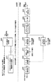
図12に示すユーザ端末は、送信部と、受信部とを備えている。受信部は、受信信号を制御情報とデータ信号に分離するチャネル分離部1400と、OFDM信号を復調するデータ情報復調部1401と、PCell及びSCell毎の下りデータ信号に対して再送確認する再送制御判定部1402とを有している。一方、送信部は、送達確認信号選択部1201と、上り共有チャネル(PUSCH)処理部1000と、第1ACK/NACK処理部1100と、第2ACK/NACK処理部1110と、SRS信号生成部1301と、DM−RS信号生成部1302と、チャネル多重部1202と、IFFT部1203と、CP付与部1204とを有している。主に、送達確認信号選択部1201、上り共有チャネル(PUSCH)処理部1000、第1ACK/NACK処理部1100及び第2ACK/NACK処理部1110を用いて、送達確認信号(再送制御信号)のフィードバックが制御される。
The user terminal shown in FIG. 12 includes a transmission unit and a reception unit. The receiving unit is a
データ情報復調部1401は、下りOFDM信号を受信し復調する。すなわち、下りOFDM信号からCPを除去し、高速フーリエ変換し、BCH信号あるいは下り制御信号が割当てられたサブキャリアを取り出し、データ復調する。複数のCCから下りOFDM信号を受信した場合には、CC毎にデータ復調する。データ情報復調部1401は、データ復調後の下り信号を再送制御判定部1402に出力する。
The
再送制御判定部1402は、受信した下りデータ信号(PDSCH信号)が誤りなく受信できたか否かを判定し、下り共有チャネル信号が誤りなく受信できていればACK、誤りが検出されればNACK、下りデータ信号が検出されなければDTXの各状態を再送確認して判定結果を出力する。セル内CAにおいて、各無線基地局との通信にそれぞれCCが割当てられている場合は、マクロ基地局は、CC毎に下りデータ信号が誤りなく受信できたか否かを判定する。一方で、セル間CAにおいては、各基地局の再送制御判定部1402がそれぞれの無線基地局に対応するCCの下りデータ信号の判定を行う。再送制御判定部1402は、判定結果を送信部(ここでは、送達確認信号選択部1201)に出力する。
The retransmission
送達確認信号選択部1201は、送達確認信号のフィードバックに適用する物理上りチャネルやPUCCHフォーマットを選択する。具体的には、上りデータ信号の送信の有無に応じて、送達確認信号を上り共有チャネル(PUSCH)に含めて送信するか、上り制御チャネル(PUCCH)で送信するかを決定する。また、上り制御チャネルで送信する場合には、送達確認信号に適用するPUCCHフォーマットを選択する。
The delivery confirmation
例えば、送達確認信号選択部1201は、PUSCHを介して上り信号(ユーザデータ)を送信する場合には、再送制御判定部1402から出力された判定結果を上り共有チャネル処理部1000に出力する。一方、送達確認信号選択部1201は、上り信号(ユーザデータ)を送信しない場合には、PUCCHフォーマット1a/1b用の第1ACK/NACK処理部1100及び/又はPUCCHフォーマット3用の第2ACK/NACK処理部1110に出力し、各送達確認信号を所定のPUCCHフォーマットで生成する。
For example, when transmitting an uplink signal (user data) via PUSCH, the delivery confirmation
送達確認信号選択部1201は、PUCCHリソースを用いて送達確認信号をフィードバックする場合、キャリアアグリゲーションを適用するセル(PCellとSCell)数に基づいて、PUCCHフォーマットを選択することができる。例えば、CAを適用するセルが2セルである場合にはチャネルセレクションを適用し、CAを適用するセルが3セルである場合にはPUCCHフォーマット3(PCellのPDCCHのみ受信した場合には、PUCCHフォーマット1a/1b)を適用する。
When the acknowledgment signal is fed back using the PUCCH resource, the acknowledgment
上り共有チャネル処理部1000は、再送制御判定部1402の判定結果に基づいて、送達確認信号のビットを決定する制御情報ビット決定部1006と、ACK/NACKビット系列を誤り訂正符号化するチャネル符号化部1007、送信すべきデータ系列を誤り訂正符号化するチャネル符号化部1001と、符号化後のデータ信号をデータ変調するデータ変調部1002、1008と、変調されたデータ信号と送達確認信号を時間多重する時間多重部1003と、時間多重した信号にDFT(Discrete Fourier Transform)するDFT部1004と、DFT後の信号をサブキャリアにマッピングするサブキャリアマッピング部1005とを有している。
Based on the determination result of retransmission
PUCCHフォーマット1a/1b用の第1ACK/NACK処理部1100は、送達確認信号の送信に用いるPUCCHリソースを制御するチャネル選択制御部1101と、PSKデータ変調を行うPSKデータ変調部1102と、PSKデータ変調部1102で変調されたデータに巡回シフトを付与する巡回シフト部1103と、巡回シフト後の信号にブロック拡散符号でブロック拡散するブロック拡散部1104と、ブロック拡散後の信号をサブキャリアにマッピングするサブキャリアマッピング部1105とを有している。
The first ACK /
チャネル選択制御部1101は、PCellのPUCCH又はSCellのPUCCHのCCEインデックスから送達確認信号の送信に利用するPUCCHリソースを決定する。例えば、セル内CAの場合、チャネルセレクションにおいて、送達確認信号の割当て候補となる複数のPUCCHリソース(例えば、図4におけるCh1〜Ch4)は、PCellのPUCCH又はSCellのPUCCHのCCEインデックスから決定される。リソース選択情報は、PSKデータ変調部1102、巡回シフト部1103、ブロック拡散部1104及びサブキャリアマッピング部1105に通知される。一方で、セル間CAの場合、送達確認信号の割当てを行うPUCCHリソースとして、Rel.10までのPUCCH format 1a/1bが利用される。つまり、各無線基地局におけるチャネル選択制御部がPUCCH format 1a/1bで用いるPUCCHリソースを決定する。
The channel selection control unit 1101 determines a PUCCH resource to be used for transmission of a delivery confirmation signal from the PCell PUCCH or the SCell PUCCH CCE index. For example, in the case of intra-cell CA, in channel selection, a plurality of PUCCH resources (for example, Ch1 to Ch4 in FIG. 4) that are candidates for delivery confirmation signal allocation are determined from the CCE index of PCell PUCCH or SCell PUCCH. . The resource selection information is notified to the PSK
PSKデータ変調部1102は、チャネル選択制御部1101から通知された情報に基づいて、位相変調(PSKデータ変調)を行う。例えば、PSKデータ変調部1102において、QPSKデータ変調による2ビットのビット情報に変調する。
The PSK
巡回シフト部1103は、CAZAC(Constant Amplitude Zero Auto Correlation)符号系列の巡回シフトを用いて直交多重を行う。具体的には、時間領域の信号を所定の巡回シフト量だけシフトする。なお、巡回シフト量はユーザ毎に異なり、巡回シフト番号に対応づけられている。巡回シフト部1103は、巡回シフト後の信号をブロック拡散部1104に出力する。ブロック拡散部(直交符号乗算手段)1104は、巡回シフト後の参照信号に直交符号を乗算する(ブロック拡散する)。ここで、参照信号に用いるOCC(ブロック拡散符号番号)については、上位レイヤからRRCシグナリングなどで通知しても良く、データシンボルのCSに予め関連付けられたOCCを用いても良い。ブロック拡散部1104は、ブロック拡散後の信号をサブキャリアマッピング部1105に出力する。
サブキャリアマッピング部(割当て部)1105は、チャネル選択制御部1101から通知された情報に基づいて、ブロック拡散後の信号をサブキャリアにマッピングする。また、サブキャリアマッピング部1105は、マッピングされた信号をチャネル多重部1202に出力する。
Subcarrier mapping section (assignment section) 1105 maps the signal after block spreading to the subcarrier based on the information notified from channel selection control section 1101. Further,
PUCCHフォーマット3用の第2ACK/NACK処理部1110は、ACK/NACKのビット系列等を誤り訂正符号化するチャネル符号化部1111と、PSKデータ変調を行うPSKデータ変調部1112と、PSKデータ変調部1112で変調されたデータにDFTするDFT部1113と、DFT後の信号にブロック拡散符号でブロック拡散するブロック拡散部1114と、ブロック拡散後の信号をサブキャリアにマッピングするサブキャリアマッピング部1115とを有している。
The second ACK /
DFT部1113は、データ変調後の信号にDFTして周波数領域の信号に変換し、DFT後の信号をブロック拡散部1114に出力する。ブロック拡散部1114は、DFT後の信号に直交符号(OCC(ブロック拡散符号番号))を乗算する。OCCについては、上位レイヤからRRCシグナリングなどで通知しても良く、データシンボルのCSに予め関連付けられたOCCを用いても良い。 The DFT unit 1113 performs DFT on the data-modulated signal and converts it to a frequency domain signal, and outputs the signal after DFT to the block spreading unit 1114. Block spreading section 1114 multiplies the signal after DFT by an orthogonal code (OCC (block spreading code number)). The OCC may be notified from the upper layer by RRC signaling or the like, or an OCC previously associated with the data symbol CS may be used.
サブキャリアマッピング部(割当て部)1115は、ブロック拡散後の信号をサブキャリアにマッピングする。また、サブキャリアマッピング部1115は、マッピングされた信号をチャネル多重部1202に出力する。なお、マッピングするPUCCHリソースは、無線基地局から上位レイヤシグナリング(例えば、RRCシグナリング)で通知される複数のSCellのリソースの中から、SCellの下り制御情報に含まれるARIで指定される所定リソースとすることができる。
A subcarrier mapping unit (allocation unit) 1115 maps the block spread signal to a subcarrier. Further, subcarrier mapping section 1115 outputs the mapped signal to channel
SRS信号生成部1301は、SRS(Sounding RS)信号を生成してチャネル多重部1202に出力する。また、DM−RS信号生成部1302は、DM−RS信号を生成してチャネル多重部1202に出力する。
SRS
チャネル多重部1202は、上り共有チャネル処理部1000、第1ACK/NACK処理部1100、第2ACK/NACK処理部1110からの信号と、SRS信号生成部1301、DM−RS信号生成部1302からの参照信号とを時間多重して、上り制御チャネル信号を含む送信信号とする。
IFFT部1203は、チャネル多重された信号をIFFTして時間領域の信号に変換する。IFFT部1203は、IFFT後の信号をCP付与部1204に出力する。CP付与部1204は、直交符号乗算後の信号にCPを付与する。そして、PCell及び/又はSCellのPUCCHリソースを用いて上り送信信号が無線基地局に対して送信される。
次に、図13を参照して、上記図12に示したユーザ端末と無線通信を行う無線基地局の機能構成について説明する。 Next, a functional configuration of a radio base station that performs radio communication with the user terminal shown in FIG. 12 will be described with reference to FIG.
図13に示す無線基地局は、送信部と、受信部とを備えている。送信部は、上りリソース(PUCCHリソース)割当て情報信号生成部2010と、他の下りリンクチャネル信号と、上りリソース割当て情報信号とを多重してOFDM信号を生成するOFDM信号生成部2020とを有する。ここで、他の下りリンクチャネル信号は、データ、参照信号、制御信号などを含む。
The radio base station illustrated in FIG. 13 includes a transmission unit and a reception unit. The transmission unit includes an uplink resource (PUCCH resource) allocation information
上りリソース割当て情報信号生成部2010は、CAZAC番号、リソースマッピング情報(RBインデックス)、巡回シフト番号、ブロック拡散符号番号(OCC番号)を含む上りリソース割当て情報信号を生成する。例えば、上りリソース割当て情報信号生成部2010は、ユーザ端末がPUCCHフォーマット3を適用する場合に上位レイヤシグナリング(例えば、RRCシグナリング)で通知する複数のPUCCHリソース候補や、ARIで通知するPUCCHリソースを決定する。
The uplink resource allocation information
上りリソース割当て情報信号生成部2010は、ユーザ端末がPUCCHフォーマット3を適用する場合に設定する複数のPUCCHリソース候補として、SCellのリソースを設定する。
Uplink resource allocation information
OFDM信号生成部2020は、他の下りデータ信号及び上りリソース割当て情報信号を含む下りリンクチャネル信号をサブキャリアにマッピングし、逆高速フーリエ変換(IFFT)し、CPを付加することにより、下り送信信号を生成する。このように生成された下り送信信号は、下りリンクでユーザ端末に送信される。
The OFDM
受信部は、受信信号からCPを除去するCP除去部2030と、受信信号を高速フーリエ変換(FFT)するFFT部2040と、FFT後の信号をデマッピングするサブキャリアデマッピング部2050と、サブキャリアデマッピング後の信号に対してブロック拡散符号(OCC)で逆拡散するブロック逆拡散部2060、2100と、サブキャリアデマッピング後の信号から巡回シフトを除去して対象とするユーザの信号を分離する巡回シフト分離部2070と、ユーザ分離後の信号及び逆拡散後の信号に対して、データ復調するデータ復調部2080と、データ復調後の信号を復号するデータ復号部2090とを有している。
The receiving unit includes a
なお、受信部の機能ブロックにはユーザデータ(PUSCH)を受信する処理ブロックが図示されていないが、ユーザデータ(PUSCH)は図示しないデータ復調部及びデータ復号部により復調され、復号される。 Although the processing block for receiving user data (PUSCH) is not shown in the functional block of the receiving unit, the user data (PUSCH) is demodulated and decoded by a data demodulating unit and a data decoding unit (not shown).
CP除去部2030は、CPに相当する部分を除去して有効な信号部分を抽出する。CP除去部2030は、CP除去後の信号をFFT部2040に出力する。FFT部2040は、受信信号をFFTして周波数領域の信号に変換する。FFT部2040は、FFT後の信号をサブキャリアデマッピング部2050に出力する。サブキャリアデマッピング部2050は、リソースマッピング情報を用いて周波数領域の信号から上り制御チャネル信号である送達確認信号を抽出する。サブキャリアデマッピング部2050は、抽出された送達確認信号をブロック逆拡散部2060、2100にそれぞれ出力する。
ブロック逆拡散部2060では、ブロック拡散、すなわち直交符号(OCC)を用いて直交多重された受信信号を、ユーザ端末で用いた直交符号で逆拡散する。そして逆拡散後の信号を巡回シフト分離部2070へ出力する。
The
巡回シフト分離部2070は、巡回シフトを用いて直交多重された制御信号を、巡回シフト番号を用いて分離する。ユーザ端末10からの上り制御信号には、ユーザ毎に異なる巡回シフト量で巡回シフトが行われている。したがって、ユーザ端末10で行われた巡回シフト量と同じ巡回シフト量だけ逆方向に巡回シフトを行うことにより、受信処理の対象とするユーザの制御信号を分離することができる。なお、ブロック逆拡散部2060、巡回シフト分離部2070は、PUCCHフォーマット1a/1bで生成された送達確認信号について処理を行う。
The cyclic
ブロック逆拡散部2100では、ブロック拡散、すなわち直交符号(OCC)を用いて直交多重された受信信号を、ユーザ端末で用いた直交符号で逆拡散する。なお、ブロック逆拡散部2100は、PUCCHフォーマット3で生成された送達確認信号について処理を行う。
データ復調部2080は、巡回シフト分離された信号又はブロック逆拡散された信号をデータ復調した後に、データ復号部2090に出力する。データ復号部2090は、データ復調部2080から出力された信号を復号してセル毎の再送制御情報(ACK/NACK等)を取得する。無線基地局は、得られた再送制御情報を用いて新規データの送信(ACKの場合)、データの再送信(NACKの場合)を行う。
The
以上のように、送達確認信号の割当て候補となる複数のPUCCHリソースとして、PCellとSCellのPUCCHリソースを利用することにより、HetNetでセル内CAを行う場合であっても、送達確認信号の割当てに必要となるPCellのPUCCHリソースの増大を抑制することが可能となる。 As described above, by using the PUCCH resources of the PCell and SCell as a plurality of PUCCH resources that are candidates for delivery confirmation signal assignment, even when performing intra-cell CA on HetNet, it is possible to assign delivery confirmation signals. It becomes possible to suppress an increase in the necessary PUCCH resources of the PCell.
本発明の範囲を逸脱しない限りにおいて、上記説明における処理部の数、処理手順については適宜変更して実施することが可能である。また、図に示される要素の各々は機能を示しており、各機能ブロックがハードウエアで実現されても良く、ソフトウエアで実現されてもよい。また、実施の形態で説明した各構成を適宜組み合わせて実施することが可能である。 As long as it does not deviate from the scope of the present invention, the number of processing units and processing procedures in the above description can be appropriately changed and implemented. Each element shown in the figure represents a function, and each functional block may be realized by hardware or software. In addition, the structures described in the embodiments can be combined as appropriate.
1 無線通信システム
10 ユーザ端末
20 無線基地局
30 上位局装置
40 コアネットワーク
1000 上り共有チャネル処理部
1001 チャネル符号化部
1002 データ変調部
1003 時間多重部
1004 DFT部
1005 サブキャリアマッピング部
1006 制御情報ビット決定部
1007 チャネル符号化部
1008 データ変調部
1100 第1ACK/NACK処理部
1101 チャネル選択制御部
1102 PSKデータ変調部
1103 巡回シフト部
1104 ブロック拡散部
1105 サブキャリアマッピング部
1110 第2ACK/NACK処理部
1111 チャネル符号化部
1112 PSKデータ変調部
1113 DFT部
1114 ブロック拡散部
1115 サブキャリアマッピング部
1201 送達確認信号選択部
1202 チャネル多重部
1203 IFFT部
1204 CP付与部
1301 SRS信号生成部
1302 DM−RS信号生成部
1400 チャネル分離部
1401 データ情報復調部
1402 再送制御判定部
2010 PUCCHリソース割当て情報信号生成部
2020 OFDM信号生成部
2030 CP除去部
2040 FFT部
2050 サブキャリアデマッピング部
2060 ブロック逆拡散部
2070 巡回シフト分離部
2080 データ復調部
2090 データ復号部
2100 ブロック逆拡散部
DESCRIPTION OF
Claims (8)
受信した下り共有チャネル信号に対する送達確認信号を生成する生成部と、
前記送達確認信号を所定の上り制御チャネルリソースで送信する送信部と、を有し、
前記送信部は、前記送達確認信号の内容及び/又は上り制御チャネルフォーマットに基づいて、プライマリセルとセカンダリセルの上り制御チャネルリソースの一方又は双方で前記送達確認信号を送信することを特徴とするユーザ端末。 A receiver for receiving a downlink shared channel signal using the component carrier flop Raimariseru and secondary cell, respectively,
A generator for generating a delivery confirmation signal for the received downlink shared channel signal;
A transmission unit for transmitting the delivery confirmation signal using a predetermined uplink control channel resource,
And the transmission unit, on the basis of the contents of the acknowledgment signal and / or uplink control channel format, and transmits the one or the acknowledgment signal in both uplink control channel resources for the primary cell and the secondary cell User terminal.
前記ユーザ端末から、前記下り共有チャネル信号に対する送達確認信号を所定の上り制御チャネルリソースで受信する受信部と、
前記送達確認信号に基づいて再送制御を行う制御部と、を有し、
前記受信部は、前記送達確認信号の内容及び/又は上り制御チャネルフォーマットに基づいて前記ユーザ端末において決定された、プライマリセルとセカンダリセルの上り制御チャネルリソースの一方又は双方で前記送達確認信号を受信することを特徴とする無線基地局。 A transmission unit for transmitting a downlink shared channel signal to the User chromatography The terminal,
A reception unit that receives a delivery confirmation signal for the downlink shared channel signal from the user terminal using a predetermined uplink control channel resource;
A control unit that performs retransmission control based on the delivery confirmation signal ,
The receiving unit receives the delivery confirmation signal in one or both of the uplink control channel resources of the primary cell and the secondary cell, determined in the user terminal based on the content of the delivery confirmation signal and / or the uplink control channel format. A radio base station.
プライマリセルとセカンダリセルのコンポーネントキャリアをそれぞれ用いて下り共有チャネル信号を受信する工程と、
受信した下り共有チャネル信号に対する送達確認信号を生成する工程と、
前記送達確認信号を所定の上り制御チャネルリソースで送信する工程と、を有し、
前記送達確認信号の内容及び/又は上り制御チャネルフォーマットに基づいて、プライマリセルとセカンダリセルの上り制御チャネルリソースの一方又は双方で前記送達確認信号を送信することを特徴とする無線通信方法。 A wireless communication method Yu over The terminal,
A step of receiving a downlink shared channel signal using the component carrier flop Raimariseru and secondary cell, respectively,
And generating acknowledgment signals for received the downlink shared channel signal,
Transmitting the acknowledgment signal with a predetermined uplink control channel resource , and
Based on the content and / or uplink control channel format before Symbol acknowledgment signal, wireless communication method and transmitting the acknowledgment signal in one or both of the uplink control channel resources for the primary cell and the secondary cell.
Priority Applications (4)
| Application Number | Priority Date | Filing Date | Title |
|---|---|---|---|
| JP2012274881A JP6180732B2 (en) | 2012-12-17 | 2012-12-17 | User terminal, radio base station, and radio communication method |
| US14/652,400 US9781705B2 (en) | 2012-12-17 | 2013-11-12 | User terminal radio base station and radio communication method |
| PCT/JP2013/080557 WO2014097776A1 (en) | 2012-12-17 | 2013-11-12 | User terminal, radio base station and radio communication method |
| CN201380066121.XA CN104871582B (en) | 2012-12-17 | 2013-11-12 | User terminal, wireless base station and wireless communications method |
Applications Claiming Priority (1)
| Application Number | Priority Date | Filing Date | Title |
|---|---|---|---|
| JP2012274881A JP6180732B2 (en) | 2012-12-17 | 2012-12-17 | User terminal, radio base station, and radio communication method |
Publications (2)
| Publication Number | Publication Date |
|---|---|
| JP2014120941A JP2014120941A (en) | 2014-06-30 |
| JP6180732B2 true JP6180732B2 (en) | 2017-08-16 |
Family
ID=50978120
Family Applications (1)
| Application Number | Title | Priority Date | Filing Date |
|---|---|---|---|
| JP2012274881A Active JP6180732B2 (en) | 2012-12-17 | 2012-12-17 | User terminal, radio base station, and radio communication method |
Country Status (4)
| Country | Link |
|---|---|
| US (1) | US9781705B2 (en) |
| JP (1) | JP6180732B2 (en) |
| CN (1) | CN104871582B (en) |
| WO (1) | WO2014097776A1 (en) |
Families Citing this family (33)
| Publication number | Priority date | Publication date | Assignee | Title |
|---|---|---|---|---|
| CN104704763B (en) * | 2012-09-06 | 2017-12-12 | Lg 电子株式会社 | Terminal is set to send the method and its device of ul ack/NACK signal in the wireless communication system using carrier aggregation technology |
| US11088807B2 (en) * | 2014-05-30 | 2021-08-10 | Apple Inc. | Application-level acknowledgements |
| CN106664188B (en) * | 2014-08-15 | 2020-08-07 | 交互数字专利控股公司 | Method and apparatus for uplink transmission and MBMS for WTRU supporting bandwidth reduction |
| US11818717B2 (en) * | 2014-12-31 | 2023-11-14 | Texas Instruments Incorporated | Method and apparatus for uplink control signaling with massive Carrier Aggregation |
| EP3242519B1 (en) * | 2015-01-29 | 2019-07-31 | Huawei Technologies Co., Ltd. | Pucch configuration method and apparatus |
| CN111148245B (en) * | 2015-01-30 | 2023-11-10 | 华为技术有限公司 | Communication method, network device, user equipment and communication system |
| US10511427B2 (en) | 2015-01-30 | 2019-12-17 | Qualcomm Incorporated | Uplink control channel for acknowledging increased number of downlink component carriers |
| US9820298B2 (en) | 2015-03-09 | 2017-11-14 | Ofinno Technologies, Llc | Scheduling request in a wireless device and wireless network |
| US9820264B2 (en) | 2015-03-09 | 2017-11-14 | Ofinno Technologies, Llc | Data and multicast signals in a wireless device and wireless network |
| US10327236B2 (en) | 2015-03-09 | 2019-06-18 | Comcast Cable Communications, Llc | Secondary cell in a wireless device and wireless network |
| US10700845B2 (en) | 2015-03-09 | 2020-06-30 | Comcast Cable Communications, Llc | Secondary cell deactivation in a wireless device and a base station |
| US10182406B2 (en) | 2015-03-09 | 2019-01-15 | Comcast Cable Communications, Llc | Power headroom report for a wireless device and a base station |
| CN107113098B (en) * | 2015-03-20 | 2021-02-09 | 华为技术有限公司 | CSI reporting and receiving method and device |
| US11641255B2 (en) | 2015-04-05 | 2023-05-02 | Comcast Cable Communications, Llc | Uplink control information transmission in a wireless network |
| US9877334B2 (en) | 2015-04-05 | 2018-01-23 | Ofinno Technologies, Llc | Cell configuration in a wireless device and wireless network |
| US10200177B2 (en) | 2015-06-12 | 2019-02-05 | Comcast Cable Communications, Llc | Scheduling request on a secondary cell of a wireless device |
| US9894681B2 (en) | 2015-06-12 | 2018-02-13 | Ofinno Technologies, Llc | Uplink scheduling in a wireless device and wireless network |
| US9948487B2 (en) | 2015-06-15 | 2018-04-17 | Ofinno Technologies, Llc | Uplink resource allocation in a wireless network |
| US11005631B2 (en) * | 2015-09-24 | 2021-05-11 | Ntt Docomo, Inc. | Terminal, base station and radio communication method for separately encoding uplink control information |
| CN108365934A (en) * | 2017-01-26 | 2018-08-03 | 索尼公司 | Wireless communications method and wireless telecom equipment |
| US10931411B2 (en) | 2017-03-13 | 2021-02-23 | Qualcomm Incorporated | Uplink ACK resource allocation in new radio |
| WO2018207376A1 (en) * | 2017-05-12 | 2018-11-15 | 株式会社Nttドコモ | User terminal and wireless communication method |
| EP3641467A4 (en) * | 2017-06-13 | 2021-01-20 | Ntt Docomo, Inc. | User terminal, wireless base station, and wireless communication method |
| CN109391406A (en) * | 2017-08-10 | 2019-02-26 | 株式会社Ntt都科摩 | Data transmission method for uplink, confirmation signal sending method, user equipment and base station |
| CN111492684B (en) * | 2017-11-02 | 2023-10-24 | 株式会社Ntt都科摩 | User terminal and wireless communication method |
| CN111758276B (en) * | 2017-12-27 | 2024-03-01 | 株式会社Ntt都科摩 | User terminal and wireless communication method |
| WO2019139691A1 (en) | 2018-01-10 | 2019-07-18 | Kyocera Corporation | Transmission of wake-up signal to mobile devices at alternate carrier frequency |
| EP3754875B1 (en) * | 2018-02-15 | 2023-07-19 | Ntt Docomo, Inc. | User terminal and wireless communication method |
| WO2019163111A1 (en) * | 2018-02-23 | 2019-08-29 | 株式会社Nttドコモ | User terminal, wireless base station, and wireless communications method |
| US11477769B2 (en) * | 2018-02-26 | 2022-10-18 | Ntt Docomo, Inc. | User terminal and radio communication method |
| EP3776895A1 (en) * | 2018-04-13 | 2021-02-17 | Telefonaktiebolaget LM Ericsson (publ) | Reference signaling for radio access networks |
| EP3989632A1 (en) * | 2019-06-21 | 2022-04-27 | Ntt Docomo, Inc. | Terminal |
| EP4114071A4 (en) * | 2020-02-27 | 2023-11-01 | Ntt Docomo, Inc. | Terminal, wireless communication method, and base station |
Family Cites Families (29)
| Publication number | Priority date | Publication date | Assignee | Title |
|---|---|---|---|---|
| US9210695B2 (en) * | 2010-04-22 | 2015-12-08 | Lg Electronics Inc. | Method and apparatus for transmitting uplink control information in a carrier aggregation system |
| US10135595B2 (en) * | 2010-06-21 | 2018-11-20 | Telefonaktiebolaget L M Ericsson (Publ) | Uplink control information (UCI) mapping indicator for long term evolution (LTE) carrier aggregation |
| US8923223B2 (en) * | 2010-08-16 | 2014-12-30 | Qualcomm Incorporated | Physical uplink control channel resource allocation for multiple component carriers |
| WO2012050340A2 (en) * | 2010-10-11 | 2012-04-19 | 엘지전자 주식회사 | Method for transmitting control information and apparatus for same |
| KR101771550B1 (en) * | 2010-10-15 | 2017-08-29 | 주식회사 골드피크이노베이션즈 | Method of Transmitting and Receiving Ack/Nack Signal and Apparatus Thereof |
| JP5873503B2 (en) * | 2010-11-11 | 2016-03-01 | エルジー エレクトロニクス インコーポレイティド | Method and apparatus for transmitting / receiving uplink control information in wireless communication system |
| US8675558B2 (en) * | 2011-01-07 | 2014-03-18 | Intel Corporation | CQI definition for transmission mode 9 in LTE-advanced |
| CN102638879A (en) * | 2011-02-12 | 2012-08-15 | 北京三星通信技术研究有限公司 | Method for allocating acknowledgement (ACK)/negative acknowledgement (NACK) channel resource |
| US8837304B2 (en) * | 2011-04-08 | 2014-09-16 | Sharp Kabushiki Kaisha | Devices for multi-group communications |
| CN103503360A (en) * | 2011-04-29 | 2014-01-08 | 交互数字专利控股公司 | Carrier aggregation of carriers with subframe restrictions |
| JP5285117B2 (en) * | 2011-05-02 | 2013-09-11 | 株式会社エヌ・ティ・ティ・ドコモ | User terminal, radio base station apparatus, radio communication system, and radio communication method |
| WO2012161510A2 (en) * | 2011-05-23 | 2012-11-29 | 엘지전자 주식회사 | Method and apparatus for transmitting control information in a wireless communication system |
| US9515808B2 (en) * | 2011-07-26 | 2016-12-06 | Qualcomm Incorporated | Transmission of control information in a wireless network with carrier aggregation |
| US9398122B2 (en) * | 2011-07-27 | 2016-07-19 | Lg Electronics Inc. | Sequence mapping method and apparatus in wireless communication system |
| WO2013025005A2 (en) * | 2011-08-12 | 2013-02-21 | 엘지전자 주식회사 | Method and device for acquiring resource for uplink control channel in wireless communication system |
| EP2742756B1 (en) * | 2011-08-12 | 2014-12-10 | Telefonaktiebolaget LM Ericsson (PUBL) | Base station, user equipment and methods therein for control timing configuration assignment in a multiple cell communications network |
| US8953532B2 (en) * | 2011-09-19 | 2015-02-10 | Futurewei Technologies, Inc. | Method and apparatus for uplink control signaling |
| US8891402B2 (en) * | 2011-09-30 | 2014-11-18 | Sharp Kabushiki Kaisha | Devices for reporting uplink information |
| CN103918203B (en) * | 2011-10-24 | 2017-08-04 | Lg电子株式会社 | Method and apparatus for distributing resource in a wireless communication system |
| CN102412883B (en) * | 2011-11-04 | 2017-07-07 | 中兴通讯股份有限公司 | The sending method and device of ascending control information |
| CN103095433B (en) * | 2011-11-04 | 2018-06-15 | 北京三星通信技术研究有限公司 | A kind of method for sending HARQ-ACK feedback information |
| US9112693B2 (en) * | 2012-03-16 | 2015-08-18 | Sharp Laboratories Of America, Inc. | Devices for sending and receiving hybrid automatic repeat request information for carrier aggregation |
| US9320062B2 (en) * | 2012-04-17 | 2016-04-19 | Qualcomm Incorporated | Communication in a heterogeneous network with carrier aggregation |
| EP2847920A1 (en) * | 2012-05-11 | 2015-03-18 | Telefonaktiebolaget L M Ericsson (PUBL) | Resources for multi-cell channel state information feedback |
| US9088977B2 (en) * | 2012-05-30 | 2015-07-21 | Intel Corporation | Hybrid automatic repeat request (HARQ) mapping for carrier aggregation (CA) |
| US9094960B2 (en) * | 2012-05-30 | 2015-07-28 | Intel Corporation | Hybrid automatic repeat request (HARQ) mapping for carrier aggregation (CA) |
| CN104509191B (en) * | 2012-07-27 | 2019-06-11 | 华为技术有限公司 | System and method for multi-point |
| CA2886214C (en) * | 2012-09-28 | 2017-10-24 | Blackberry Limited | Methods and apparatus for enabling enhancements to flexible subframes in lte heterogeneous networks |
| US9276726B2 (en) * | 2012-12-11 | 2016-03-01 | Samsung Electronics Co., Ltd. | Transmissions/receptions of uplink acknowledgement signals in wireless networks |
-
2012
- 2012-12-17 JP JP2012274881A patent/JP6180732B2/en active Active
-
2013
- 2013-11-12 CN CN201380066121.XA patent/CN104871582B/en active Active
- 2013-11-12 WO PCT/JP2013/080557 patent/WO2014097776A1/en active Application Filing
- 2013-11-12 US US14/652,400 patent/US9781705B2/en active Active
Also Published As
| Publication number | Publication date |
|---|---|
| WO2014097776A1 (en) | 2014-06-26 |
| CN104871582B (en) | 2019-10-11 |
| CN104871582A (en) | 2015-08-26 |
| US20150327230A1 (en) | 2015-11-12 |
| US9781705B2 (en) | 2017-10-03 |
| JP2014120941A (en) | 2014-06-30 |
Similar Documents
| Publication | Publication Date | Title |
|---|---|---|
| JP6180732B2 (en) | User terminal, radio base station, and radio communication method | |
| JP6027368B2 (en) | User terminal, wireless communication method, and wireless communication system | |
| JP5285117B2 (en) | User terminal, radio base station apparatus, radio communication system, and radio communication method | |
| JP5933774B2 (en) | Mobile station apparatus, base station apparatus, and communication method | |
| WO2013141214A1 (en) | Wireless communications system, wireless base station device, user terminal, and wireless resource allocation method | |
| JP5979968B2 (en) | User terminal, wireless communication method, and wireless communication system | |
| JP5612770B2 (en) | Radio communication system, radio communication method, radio base station apparatus, and user terminal | |
| JP5801694B2 (en) | Radio communication system, radio base station apparatus, user terminal, and radio communication method | |
| JP2011142598A (en) | Radio communication control method, base station device, and mobile terminal | |
| JP5766834B2 (en) | Radio base station apparatus, mobile terminal apparatus, radio communication system, and radio communication method | |
| JP5137992B2 (en) | Base station apparatus, mobile terminal apparatus and communication control method | |
| JP5490737B2 (en) | User terminal, radio base station apparatus and radio communication method | |
| US9077532B2 (en) | User terminal and base station apparatus | |
| KR101623391B1 (en) | Mobile terminal apparatus and wireless communication method | |
| JP5478645B2 (en) | Wireless communication system |
Legal Events
| Date | Code | Title | Description |
|---|---|---|---|
| A621 | Written request for application examination |
Free format text: JAPANESE INTERMEDIATE CODE: A621 Effective date: 20151215 |
|
| A131 | Notification of reasons for refusal |
Free format text: JAPANESE INTERMEDIATE CODE: A131 Effective date: 20170124 |
|
| A601 | Written request for extension of time |
Free format text: JAPANESE INTERMEDIATE CODE: A601 Effective date: 20170322 |
|
| A521 | Request for written amendment filed |
Free format text: JAPANESE INTERMEDIATE CODE: A523 Effective date: 20170522 |
|
| TRDD | Decision of grant or rejection written | ||
| A01 | Written decision to grant a patent or to grant a registration (utility model) |
Free format text: JAPANESE INTERMEDIATE CODE: A01 Effective date: 20170620 |
|
| A61 | First payment of annual fees (during grant procedure) |
Free format text: JAPANESE INTERMEDIATE CODE: A61 Effective date: 20170719 |
|
| R150 | Certificate of patent or registration of utility model |
Ref document number: 6180732 Country of ref document: JP Free format text: JAPANESE INTERMEDIATE CODE: R150 |
|
| R250 | Receipt of annual fees |
Free format text: JAPANESE INTERMEDIATE CODE: R250 |
|
| R250 | Receipt of annual fees |
Free format text: JAPANESE INTERMEDIATE CODE: R250 |
|
| R250 | Receipt of annual fees |
Free format text: JAPANESE INTERMEDIATE CODE: R250 |
|
| R250 | Receipt of annual fees |
Free format text: JAPANESE INTERMEDIATE CODE: R250 |