EP2639984A2 - Uplink control information transmitting/receiving method and device in a wireless communication system - Google Patents
Uplink control information transmitting/receiving method and device in a wireless communication system Download PDFInfo
- Publication number
- EP2639984A2 EP2639984A2 EP11839830.4A EP11839830A EP2639984A2 EP 2639984 A2 EP2639984 A2 EP 2639984A2 EP 11839830 A EP11839830 A EP 11839830A EP 2639984 A2 EP2639984 A2 EP 2639984A2
- Authority
- EP
- European Patent Office
- Prior art keywords
- ack
- nack
- pdcch
- pucch
- pcell
- Prior art date
- Legal status (The legal status is an assumption and is not a legal conclusion. Google has not performed a legal analysis and makes no representation as to the accuracy of the status listed.)
- Granted
Links
- 238000000034 method Methods 0.000 title claims abstract description 137
- 238000004891 communication Methods 0.000 title claims abstract description 51
- 230000005540 biological transmission Effects 0.000 claims abstract description 327
- 101000741965 Homo sapiens Inactive tyrosine-protein kinase PRAG1 Proteins 0.000 claims description 889
- 102100038659 Inactive tyrosine-protein kinase PRAG1 Human genes 0.000 claims description 889
- 125000004122 cyclic group Chemical group 0.000 claims description 7
- 102100036409 Activated CDC42 kinase 1 Human genes 0.000 description 871
- 101000928956 Homo sapiens Activated CDC42 kinase 1 Proteins 0.000 description 869
- 230000004044 response Effects 0.000 description 197
- 238000013507 mapping Methods 0.000 description 68
- 238000013468 resource allocation Methods 0.000 description 43
- 230000004913 activation Effects 0.000 description 33
- 239000000969 carrier Substances 0.000 description 33
- 230000011664 signaling Effects 0.000 description 26
- 238000009825 accumulation Methods 0.000 description 23
- 230000036961 partial effect Effects 0.000 description 20
- 238000010586 diagram Methods 0.000 description 18
- 108010003272 Hyaluronate lyase Proteins 0.000 description 17
- 102100038509 E3 ubiquitin-protein ligase ARIH1 Human genes 0.000 description 16
- 101000808922 Homo sapiens E3 ubiquitin-protein ligase ARIH1 Proteins 0.000 description 16
- 230000015654 memory Effects 0.000 description 15
- 230000007480 spreading Effects 0.000 description 14
- 230000006870 function Effects 0.000 description 13
- 238000012545 processing Methods 0.000 description 13
- 230000002441 reversible effect Effects 0.000 description 13
- 238000001514 detection method Methods 0.000 description 11
- 230000002829 reductive effect Effects 0.000 description 11
- 241001633942 Dais Species 0.000 description 6
- 230000008859 change Effects 0.000 description 6
- 230000008569 process Effects 0.000 description 6
- 230000006399 behavior Effects 0.000 description 5
- 238000012360 testing method Methods 0.000 description 5
- 230000002776 aggregation Effects 0.000 description 4
- 238000004220 aggregation Methods 0.000 description 4
- 238000006243 chemical reaction Methods 0.000 description 4
- 230000000737 periodic effect Effects 0.000 description 4
- 239000000470 constituent Substances 0.000 description 3
- 238000005516 engineering process Methods 0.000 description 3
- 239000011159 matrix material Substances 0.000 description 3
- 230000004048 modification Effects 0.000 description 3
- 238000012986 modification Methods 0.000 description 3
- 238000010187 selection method Methods 0.000 description 3
- 101100532684 Arabidopsis thaliana SCC3 gene Proteins 0.000 description 2
- 102100035590 Cohesin subunit SA-1 Human genes 0.000 description 2
- 101001093139 Homo sapiens MAU2 chromatid cohesion factor homolog Proteins 0.000 description 2
- 101100043640 Homo sapiens STAG1 gene Proteins 0.000 description 2
- 102100036309 MAU2 chromatid cohesion factor homolog Human genes 0.000 description 2
- 101100062195 Saccharomyces cerevisiae (strain ATCC 204508 / S288c) CPR4 gene Proteins 0.000 description 2
- 101100532687 Saccharomyces cerevisiae (strain ATCC 204508 / S288c) IRR1 gene Proteins 0.000 description 2
- 230000004931 aggregating effect Effects 0.000 description 2
- 230000001174 ascending effect Effects 0.000 description 2
- 239000000872 buffer Substances 0.000 description 2
- 239000002131 composite material Substances 0.000 description 2
- 238000010276 construction Methods 0.000 description 2
- 230000003247 decreasing effect Effects 0.000 description 2
- 230000000694 effects Effects 0.000 description 2
- 230000007274 generation of a signal involved in cell-cell signaling Effects 0.000 description 2
- 238000010295 mobile communication Methods 0.000 description 2
- 238000003672 processing method Methods 0.000 description 2
- 230000000153 supplemental effect Effects 0.000 description 2
- 102100029952 Double-strand-break repair protein rad21 homolog Human genes 0.000 description 1
- 241000760358 Enodes Species 0.000 description 1
- 101000584942 Homo sapiens Double-strand-break repair protein rad21 homolog Proteins 0.000 description 1
- 101001024120 Homo sapiens Nipped-B-like protein Proteins 0.000 description 1
- 230000027311 M phase Effects 0.000 description 1
- 102100035377 Nipped-B-like protein Human genes 0.000 description 1
- 229920006934 PMI Polymers 0.000 description 1
- 102100035362 Phosphomannomutase 2 Human genes 0.000 description 1
- 230000003213 activating effect Effects 0.000 description 1
- 238000003491 array Methods 0.000 description 1
- 238000004364 calculation method Methods 0.000 description 1
- 230000001419 dependent effect Effects 0.000 description 1
- 238000013461 design Methods 0.000 description 1
- 230000007774 longterm Effects 0.000 description 1
- 238000012423 maintenance Methods 0.000 description 1
- 238000007726 management method Methods 0.000 description 1
- 238000012544 monitoring process Methods 0.000 description 1
- 230000003287 optical effect Effects 0.000 description 1
- 230000002085 persistent effect Effects 0.000 description 1
- 229920000915 polyvinyl chloride Polymers 0.000 description 1
- 230000009467 reduction Effects 0.000 description 1
- 230000003252 repetitive effect Effects 0.000 description 1
- 238000005070 sampling Methods 0.000 description 1
- 230000008054 signal transmission Effects 0.000 description 1
- 230000003068 static effect Effects 0.000 description 1
- 238000012546 transfer Methods 0.000 description 1
- 230000009466 transformation Effects 0.000 description 1
Images


Classifications
-
- H—ELECTRICITY
- H04—ELECTRIC COMMUNICATION TECHNIQUE
- H04L—TRANSMISSION OF DIGITAL INFORMATION, e.g. TELEGRAPHIC COMMUNICATION
- H04L5/00—Arrangements affording multiple use of the transmission path
- H04L5/003—Arrangements for allocating sub-channels of the transmission path
- H04L5/0053—Allocation of signaling, i.e. of overhead other than pilot signals
- H04L5/0055—Physical resource allocation for ACK/NACK
-
- H—ELECTRICITY
- H04—ELECTRIC COMMUNICATION TECHNIQUE
- H04L—TRANSMISSION OF DIGITAL INFORMATION, e.g. TELEGRAPHIC COMMUNICATION
- H04L1/00—Arrangements for detecting or preventing errors in the information received
- H04L1/12—Arrangements for detecting or preventing errors in the information received by using return channel
- H04L1/16—Arrangements for detecting or preventing errors in the information received by using return channel in which the return channel carries supervisory signals, e.g. repetition request signals
- H04L1/1607—Details of the supervisory signal
- H04L1/1671—Details of the supervisory signal the supervisory signal being transmitted together with control information
-
- H—ELECTRICITY
- H04—ELECTRIC COMMUNICATION TECHNIQUE
- H04L—TRANSMISSION OF DIGITAL INFORMATION, e.g. TELEGRAPHIC COMMUNICATION
- H04L1/00—Arrangements for detecting or preventing errors in the information received
- H04L1/12—Arrangements for detecting or preventing errors in the information received by using return channel
- H04L1/16—Arrangements for detecting or preventing errors in the information received by using return channel in which the return channel carries supervisory signals, e.g. repetition request signals
- H04L1/18—Automatic repetition systems, e.g. Van Duuren systems
- H04L1/1812—Hybrid protocols; Hybrid automatic repeat request [HARQ]
-
- H—ELECTRICITY
- H04—ELECTRIC COMMUNICATION TECHNIQUE
- H04L—TRANSMISSION OF DIGITAL INFORMATION, e.g. TELEGRAPHIC COMMUNICATION
- H04L1/00—Arrangements for detecting or preventing errors in the information received
- H04L1/12—Arrangements for detecting or preventing errors in the information received by using return channel
- H04L1/16—Arrangements for detecting or preventing errors in the information received by using return channel in which the return channel carries supervisory signals, e.g. repetition request signals
- H04L1/18—Automatic repetition systems, e.g. Van Duuren systems
- H04L1/1829—Arrangements specially adapted for the receiver end
- H04L1/1854—Scheduling and prioritising arrangements
-
- H—ELECTRICITY
- H04—ELECTRIC COMMUNICATION TECHNIQUE
- H04L—TRANSMISSION OF DIGITAL INFORMATION, e.g. TELEGRAPHIC COMMUNICATION
- H04L27/00—Modulated-carrier systems
- H04L27/26—Systems using multi-frequency codes
- H04L27/2601—Multicarrier modulation systems
- H04L27/2626—Arrangements specific to the transmitter only
- H04L27/2627—Modulators
- H04L27/2634—Inverse fast Fourier transform [IFFT] or inverse discrete Fourier transform [IDFT] modulators in combination with other circuits for modulation
- H04L27/2636—Inverse fast Fourier transform [IFFT] or inverse discrete Fourier transform [IDFT] modulators in combination with other circuits for modulation with FFT or DFT modulators, e.g. standard single-carrier frequency-division multiple access [SC-FDMA] transmitter or DFT spread orthogonal frequency division multiplexing [DFT-SOFDM]
-
- H—ELECTRICITY
- H04—ELECTRIC COMMUNICATION TECHNIQUE
- H04L—TRANSMISSION OF DIGITAL INFORMATION, e.g. TELEGRAPHIC COMMUNICATION
- H04L5/00—Arrangements affording multiple use of the transmission path
- H04L5/0001—Arrangements for dividing the transmission path
- H04L5/0014—Three-dimensional division
- H04L5/0016—Time-frequency-code
- H04L5/0017—Time-frequency-code in which a distinct code is applied, as a temporal sequence, to each frequency
-
- H—ELECTRICITY
- H04—ELECTRIC COMMUNICATION TECHNIQUE
- H04L—TRANSMISSION OF DIGITAL INFORMATION, e.g. TELEGRAPHIC COMMUNICATION
- H04L5/00—Arrangements affording multiple use of the transmission path
- H04L5/14—Two-way operation using the same type of signal, i.e. duplex
-
- H—ELECTRICITY
- H04—ELECTRIC COMMUNICATION TECHNIQUE
- H04L—TRANSMISSION OF DIGITAL INFORMATION, e.g. TELEGRAPHIC COMMUNICATION
- H04L5/00—Arrangements affording multiple use of the transmission path
- H04L5/22—Arrangements affording multiple use of the transmission path using time-division multiplexing
-
- H—ELECTRICITY
- H04—ELECTRIC COMMUNICATION TECHNIQUE
- H04W—WIRELESS COMMUNICATION NETWORKS
- H04W72/00—Local resource management
- H04W72/04—Wireless resource allocation
-
- H—ELECTRICITY
- H04—ELECTRIC COMMUNICATION TECHNIQUE
- H04W—WIRELESS COMMUNICATION NETWORKS
- H04W72/00—Local resource management
- H04W72/04—Wireless resource allocation
- H04W72/044—Wireless resource allocation based on the type of the allocated resource
- H04W72/0446—Resources in time domain, e.g. slots or frames
-
- H—ELECTRICITY
- H04—ELECTRIC COMMUNICATION TECHNIQUE
- H04W—WIRELESS COMMUNICATION NETWORKS
- H04W72/00—Local resource management
- H04W72/20—Control channels or signalling for resource management
- H04W72/21—Control channels or signalling for resource management in the uplink direction of a wireless link, i.e. towards the network
-
- H—ELECTRICITY
- H04—ELECTRIC COMMUNICATION TECHNIQUE
- H04W—WIRELESS COMMUNICATION NETWORKS
- H04W72/00—Local resource management
- H04W72/20—Control channels or signalling for resource management
- H04W72/23—Control channels or signalling for resource management in the downlink direction of a wireless link, i.e. towards a terminal
-
- H—ELECTRICITY
- H04—ELECTRIC COMMUNICATION TECHNIQUE
- H04L—TRANSMISSION OF DIGITAL INFORMATION, e.g. TELEGRAPHIC COMMUNICATION
- H04L1/00—Arrangements for detecting or preventing errors in the information received
- H04L1/0001—Systems modifying transmission characteristics according to link quality, e.g. power backoff
- H04L1/0023—Systems modifying transmission characteristics according to link quality, e.g. power backoff characterised by the signalling
- H04L1/0026—Transmission of channel quality indication
-
- H—ELECTRICITY
- H04—ELECTRIC COMMUNICATION TECHNIQUE
- H04L—TRANSMISSION OF DIGITAL INFORMATION, e.g. TELEGRAPHIC COMMUNICATION
- H04L27/00—Modulated-carrier systems
- H04L27/26—Systems using multi-frequency codes
- H04L27/2601—Multicarrier modulation systems
- H04L27/2647—Arrangements specific to the receiver only
-
- H—ELECTRICITY
- H04—ELECTRIC COMMUNICATION TECHNIQUE
- H04L—TRANSMISSION OF DIGITAL INFORMATION, e.g. TELEGRAPHIC COMMUNICATION
- H04L5/00—Arrangements affording multiple use of the transmission path
- H04L5/0001—Arrangements for dividing the transmission path
- H04L5/0003—Two-dimensional division
- H04L5/0005—Time-frequency
- H04L5/0007—Time-frequency the frequencies being orthogonal, e.g. OFDM(A), DMT
- H04L5/001—Time-frequency the frequencies being orthogonal, e.g. OFDM(A), DMT the frequencies being arranged in component carriers
-
- H—ELECTRICITY
- H04—ELECTRIC COMMUNICATION TECHNIQUE
- H04W—WIRELESS COMMUNICATION NETWORKS
- H04W72/00—Local resource management
- H04W72/12—Wireless traffic scheduling
- H04W72/1263—Mapping of traffic onto schedule, e.g. scheduled allocation or multiplexing of flows
- H04W72/1268—Mapping of traffic onto schedule, e.g. scheduled allocation or multiplexing of flows of uplink data flows
-
- H—ELECTRICITY
- H04—ELECTRIC COMMUNICATION TECHNIQUE
- H04W—WIRELESS COMMUNICATION NETWORKS
- H04W74/00—Wireless channel access, e.g. scheduled or random access
- H04W74/002—Transmission of channel access control information
- H04W74/004—Transmission of channel access control information in the uplink, i.e. towards network
Definitions
- the present invention relates to a radio communication system, and more particularly, to a method and apparatus for transmitting and receiving uplink control information.
- a wireless communication system is a multiple access system capable of supporting communication with multiple users by sharing available system resources (bandwidth, transmission power, etc.).
- Multiple access systems include, for example, a Code Division Multiple Access (CDMA) system, a Frequency Division Multiple Access (FDMA) system, a Time Division Multiple Access (TDMA) system, an Orthogonal Frequency Division Multiple Access (OFDMA) system, a Single Carrier Frequency Division Multiple Access (SC-FDMA) system, and a Multi-Carrier Frequency Division Multiple Access (MC-FDMA) system.
- CDMA Code Division Multiple Access
- FDMA Frequency Division Multiple Access
- TDMA Time Division Multiple Access
- OFDMA Orthogonal Frequency Division Multiple Access
- SC-FDMA Single Carrier Frequency Division Multiple Access
- MC-FDMA Multi-Carrier Frequency Division Multiple Access
- the object of the present invention can be achieved by providing a method for transmitting Acknowledgement/Negative Acknowledgement (ACK/NACK) information at a User Equipment (UE) in a wireless communication system, including determining whether transmission of a scheduling request is configured in one subframe in which ACK/NACK information for downlink transmission is to be transmitted; determining a Physical Uplink Control Channel (PUCCH) format and resource through which the ACK/NACK information is to be transmitted; and transmitting the ACK/NACK information using the PUCCH format and resource, wherein, if transmission of the scheduling request is configured in the one subframe, the ACK/NACK information and the scheduling request are transmitted using PUCCH format 1a/1b, when the ACK/NACK information corresponds only to a Physical Downlink Shared Channel (PDSCH) received only on a Primary Cell (PCell).
- PDSCH Physical Downlink Shared Channel
- a User Equipment for transmitting Acknowledgement/Negative Acknowledgement (ACK/NACK) information in a wireless communication system, including a reception module for receiving a downlink signal from a Base Station (BS); a transmission module for transmitting an uplink signal to the BS; and a processor for controlling the UE including the reception module and the transmission module, wherein the processor is configured to determine whether transmission of a scheduling request is configured in one subframe in which ACK/NACK information for downlink transmission is to be transmitted, determine a Physical Uplink Control Channel (PUCCH) format and resource through which the ACK/NACK information is to be transmitted, and transmit the ACK/NACK information using the PUCCH format and resource through the transmission module, and wherein, if transmission of the scheduling request is configured in the one subframe, the ACK/NACK information and the scheduling request are transmitted using PUCCH format 1a/1b, when the ACK/NACK information corresponds only to a Physical Downlink Shared Channel
- PUCCH Physical Uplink Control Channel
- the ACK/NACK information and the scheduling request may be transmitted using PUCCH format 1a/1b, when the ACK/NACK information corresponds only to a PDCCH indicating Semi-Persistent Scheduling (SPS) release received only on the PCell.
- SPS Semi-Persistent Scheduling
- the ACK/NACK information may be transmitted on a PUCCH resource allocated for the scheduling request and, in the case of a negative scheduling request, the ACK/NACK information may be transmitted on a PUCCH resource allocated for the ACK/NACK information.
- the ACK/NACK information and the scheduling request may be multiplexed and transmitted using PUCCH format 3, unless the ACK/NACK information corresponds only to a PDSCH received only on the PCell or corresponds only to a PDCCH indicating downlink SPS release received only on the PCell.
- Transmission of the scheduling request in the one subframe may be configured by a higher layer.
- the ACK/NACK information for downlink transmission received in a subframe n-4 may be transmitted in a subframe n.
- the wireless communication system may be a Frequency Division Duplex (FDD) system.
- FDD Frequency Division Duplex
- More than one serving cell may be configured for the UE and the more than one serving cell may include the PCell and at least one Secondary Cell (SCell).
- SCell Secondary Cell
- a method for transmitting Acknowledgement/Negative Acknowledgement (ACK/NACK) information at a User Equipment (UE) in a wireless communication system including determining whether transmission of channel state information is configured in one subframe in which ACK/NACK information for downlink transmission is to be transmitted; determining a Physical Uplink Control Channel (PUCCH) format and resource through which the ACK/NACK information is to be transmitted; and transmitting the ACK/NACK information using the PUCCH format and resource, wherein, if transmission of the channel state information is configured in the one subframe, the ACK/NACK information and the channel state information are transmitted using PUCCH format 2/2a/2b, when the ACK/NACK information corresponds only to a Physical Downlink Shared Channel (PDSCH) received only on a Primary Cell (PCell).
- PDSCH Physical Downlink Shared Channel
- a User Equipment for transmitting Acknowledgement/Negative Acknowledgement (ACK/NACK) information in a wireless communication system, including a reception module for receiving a downlink signal from a Base Station (BS); a transmission module for transmitting an uplink signal to the BS; and a processor for controlling the UE including the reception module and the transmission module, wherein the processor is configured to determine whether transmission of channel state information is configured in one subframe in which ACK/NACK information for downlink transmission is to be transmitted, determine a Physical Uplink Control Channel (PUCCH) format and resource through which the ACK/NACK information is to be transmitted, and transmit the ACK/NACK information using the PUCCH format and resource through the transmission module, and wherein, if transmission of the channel state information is configured in the one subframe, the ACK/NACK information and the channel state information are transmitted using PUCCH format 2/2a/2b, when the ACK/NACK information corresponds only to a Physical Downlink Share
- PUCCH Physical Uplink Control Channel
- the ACK/NACK information and the channel state information may be transmitted using PUCCH format 2/2a/2b, when the ACK/NACK information corresponds only to a PDCCH indicating Semi-Persistent Scheduling (SPS) release received only on the PCell.
- SPS Semi-Persistent Scheduling
- Simultaneous transmission of the ACK/NACK information and the channel state information may be configured by a higher layer.
- the channel state information may be periodically transmitted through a PUCCH.
- the ACK/NACK information and the channel state information may be multiplexed and transmitted using PUCCH format 2a/2b and, if the one subframe is configured with an extended CP, the ACK/NACK information and the channel state information may be joint-coded and transmitted using PUCCH format 2.
- CP Cyclic Prefix
- the ACK/NACK information for downlink transmission received in a subframe n-4 is transmitted in a subframe n.
- the wireless communication system may be a Frequency Division Duplex (FDD) system.
- FDD Frequency Division Duplex
- More than one serving cell may be configured for the UE and the more than one serving cell may include the PCell and at least one Secondary Cell (SCell).
- SCell Secondary Cell
- control information can be efficiently transmitted in a wireless communication system. Further, a channel format and a signal processing method for efficiently transmitting control information are provided. Furthermore, resources for control information transmission can be efficiently allocated.
- the BS refers to a terminal node of a network communicating directly with the terminal.
- a specific operation described as being performed by the BS may be performed by an upper node of the BS.
- BS may be replaced with terms such as fixed station, Node B, eNode B (eNB), Access Point (AP), etc.
- BS may be used as a concept including a cell or a sector.
- 'relay' may be replaced with terms such as Relay Node (RN), Relay Station (RS), etc.
- RS Relay Station
- 'terminal' may be replaced with terms such as User Equipment (UE), Mobile Station (MS), Mobile Subscriber Station (MSS), Subscriber Station (SS), etc.
- the embodiments of the present invention can be supported by standard documents disclosed in at least one of wireless access systems including an Institute of Electrical and Electronics Engineers (IEEE) 802 system, a 3 rd Generation Partnership Project (3GPP) system, a 3GPP Long Term Evolution (LTE) system, a 3GPP LTE-Advanced (LTE-A) system, and a 3GPP2 system.
- 3GPP 3 rd Generation Partnership Project
- LTE Long Term Evolution
- LTE-A 3GPP LTE-Advanced
- CDMA Code Division Multiple Access
- FDMA Frequency Division Multiple Access
- TDMA Time Division Multiple Access
- OFDMA Orthogonal Frequency Division Multiple Access
- SC-FDMA Single Carrier Frequency Division Multiple Access
- CDMA may be embodied through radio technology such as Universal Terrestrial Radio Access (UTRA) or CDMA2000.
- TDMA may be embodied through radio technology such as Global System for Mobile communications (GSM)/General Packet Radio Service (GPRS)/Enhanced Data Rates for GSM Evolution (EDGE).
- GSM Global System for Mobile communications
- GPRS General Packet Radio Service
- EDGE Enhanced Data Rates for GSM Evolution
- OFDMA may be embodied through radio technology such as Institute of Electrical and Electronics Engineers (IEEE) 802.11 (Wi-Fi), IEEE 802.16 (WiMAX), IEEE 802-20, and Evolved UTRA (E-UTRA).
- IEEE Institute of Electrical and Electronics Engineers
- Wi-Fi Wi-Fi
- WiMAX WiMAX
- IEEE 802-20 Evolved UTRA
- E-UTRA Evolved UTRA
- UTRA is a part of the Universal Mobile Telecommunications System (UMTS).
- 3GPP LTE is a part of Evolved UMTS (E-UMTS) using E-UTRA.
- 3GPP LTE employs OFDMA in downlink and employs SC-FDMA in uplink.
- LTE-A is an evolved version of 3GPP LTE.
- WiMAX can be explained by an IEEE 802.16e (WirelessMAN-OFDMA Reference System) and an advanced IEEE 802.16m (WirelessMAN-OFDMA Advanced System).
- IEEE 802.16e WirelessMAN-OFDMA Reference System
- advanced IEEE 802.16m WirelessMAN-OFDMA Advanced System
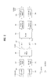
- FIG. 1 is a block diagram illustrating constituent elements of a UE and a BS performing the present invention.
- the UE operates as a transmitter on uplink and as a receiver on downlink.
- the BS operates as a receiver on uplink and as a transmitter on downlink.
- the UE and the BS include antennas 500a and 500b for receiving information, data, signals, and/or messages, transmitters 100a and 100b for transmitting messages by controlling the antennas, receivers 300a and 300b for receiving messages by controlling the antennas, and memories 200a and 200b for storing various types of information related to communication in a wireless communication system.
- the UE and the BS further include processors 400a and 400b connected operationally to constitute elements of the transmitters, the receivers, and the memories included in the UE or BS, for performing the present invention by controlling the constituent elements.
- the transmitter 100a, the receiver 300a, the memory 200a, and the processor 400a of the UE may be configured as independent components by separate chips or two or more thereof may be integrated into one chip.
- the transmitter 100b, the receiver 300b, the memory 200b, and the processor 400b of the BS may be configured as independent components by separate chips or two or more thereof may be integrated into one chip.
- the transmitter and the receiver may be integrated into a single transceiver in the UE or the BS.
- the antennas 500a and 500b transmit signals generated from the transmitters 100a and 100b to the outside or receive signals from the outside and provide the received signals to the receivers 300a and 300b.
- the antennas 500a and 500b are also referred to as antenna ports.
- Each antenna port may correspond to one physical antenna or may be configured by a combination of more than one physical antenna element.
- a signal transmitted through each antenna port cannot be decomposed any more by the receiving device 20.
- a Reference Signal (RS) transmitted in correspondence to the antenna port defines an antenna port viewed from the UE and enables the UE to perform channel estimation for the antenna port, irrespective of whether a channel is a single radio channel from one physical channel or composite channels from a plurality of physical antenna elements including the antenna port.
- RS Reference Signal
- an antenna port is defined such that a channel for transmitting a symbol on the antenna port can be derived from the channel through which another symbol on the same antenna port is transmitted.
- a transmitter and a receiver support Multiple Input Multiple Output (MIMO) in which data is transmitted and received using a plurality of antennas, each of the transmitter and the receiver may be connected to two or more antennas.
- MIMO Multiple Input Multiple Output
- the processor 400a or 400b generally controls overall operation of the modules of the UE or the BS. Especially, the processors 400a and 400b may perform various control functions for implementing the present invention, a Medium Access Control (MAC) frame conversion control function based on service characteristics and a propagation environment, a power saving mode function for controlling an idle-mode operation, a handover function, an authentication and encryption function, etc.
- the processors 400a and 400b may be called controllers, microcontrollers, microprocessors, or microcomputers. Meanwhile, the processors 400a and 400b may be configured as hardware, firmware, software, or a combination of hardware, firmware, and software.
- the processors 400a and 400b may include Application Specific Integrated Circuits (ASICs), Digital Signal Processors (DSPs), Digital Signal Processing Devices (DSPDs), Programmable Logic Devices (PLDs), Field Programmable Gate Arrays (FPGAs), etc. which are configured to implement the present invention.
- ASICs Application Specific Integrated Circuits
- DSPs Digital Signal Processors
- DSPDs Digital Signal Processing Devices
- PLDs Programmable Logic Devices
- FPGAs Field Programmable Gate Arrays
- firmware or software may be configured so as to include a module, a procedure, a function, etc. that perform the functions or operations of the present invention.
- the firmware or software configured to implement the present invention may be included in the processors 400a and 400b, or may be stored in the memories 200a and 200b and executed by the processors 400a and 400b.
- the transmitters 100a and 100b encode and modulate signals and/or data which are scheduled by the processors 400a and 400b or by schedulers connected to the processors and which are transmitted to the outside and transmit the modulated signals and/or data to the antennas 500a and 500b.
- the transmitters 100a and 100b convert data streams to be transmitted into K layers through demultiplexing, channel coding, and modulation.
- the K layers are transmitted through the antennas 500a and 500b via transmission processors of the transmitters.
- the transmitters 100a and 100b and the receivers 300a and 300b of the UE and the BS may be configured differently according to operations of processing a transmission signal and a received signal.
- the memories 200a and 200b may store programs for processing and control in the processors 400a and 400b and may temporarily store input and output information.
- the memories 200a and 200b may function as buffers.
- the memories 200a and 200b may be configured using a flash memory type, a hard disk type, a multimedia card micro type, a card type memory (e.g. a Secure Digital (SD) or extreme Digital (XD) memory), a Random Access Memory (RAM), a Static Random Access Memory (SRAM), a Read-Only Memory (ROM), an Electrically Erasable Programmable Read-Only Memory (EEPROM), a Programmable Read-Only Memory (PROM), a magnetic memory, a magnetic disk, an optical disc, etc.
- SD Secure Digital
- XD extreme Digital
- RAM Random Access Memory
- SRAM Static Random Access Memory
- ROM Read-Only Memory
- EEPROM Electrically Erasable Programmable Read-Only Memory
- PROM Programmable Read-Only Memory
- FIG. 2 illustrates an exemplary structure of a transmitter in each of the UE and the BS. Operations of the transmitters 100a and 100b will be described below in more detail with reference to FIG. 2 .
- each of the transmitters 100a and 100b include scramblers 301, modulation mappers 302, a layer mapper 303, a precoder 304, Resource Element (RE) mappers 305, and Orthogonal Frequency Division Multiplexing (OFDM) signal generators 306.
- scramblers 301 include scramblers 301, modulation mappers 302, a layer mapper 303, a precoder 304, Resource Element (RE) mappers 305, and Orthogonal Frequency Division Multiplexing (OFDM) signal generators 306.
- OFDM Orthogonal Frequency Division Multiplexing
- the transmitters 100a and 100b may transmit more than one codeword.
- the scramblers 301 scramble the coded bits of each codeword, for transmission on a physical channel.
- a codeword may be referred to as a data stream and is equivalent to a data block provided from a MAC layer.
- the data block provided from the MAC layer is referred to as a transport block.
- the modulation mappers 302 modulate the scrambled bits into complex-valued modulation symbols.
- the modulation mappers 302 may modulate the scrambled bits to complex-valued modulation symbols representing positions on signal constellation according to a predetermined modulation scheme.
- the modulation scheme is not limited and m-Phase Shift Keying (m-PSK) and m-Quadrature Amplitude Modulation (m-QAM) may be used to modulate the coded data.
- the layer mapper 303 maps the complex-valued modulation symbols to one or several transmission layers.
- the precoder 304 may precode the complex modulation symbols on each layer, for transmission through the antenna ports. More specifically, the precoder 304 generates antenna-specific symbols by processing the complex-valued modulation symbols for multiple transmission antennas 500-1 to 500-N t in a MIMO scheme and distributes the antenna-specific symbols to the RE mappers 305. That is, the precoder 304 maps the transmission layers to the antenna ports. The precoder 304 may multiply an output x of the layer mapper 303 by an N t ⁇ M t precoding matrix W and output the resulting product in the form of an N t ⁇ M F matrix z.
- the RE mappers 305 map/allocate the complex-valued modulation symbols for the respective antenna ports to REs.
- the RE mappers 305 may allocate the complex-valued modulation symbols for the respective antenna ports to appropriate subcarriers and may multiplex the same according to UEs.
- the OFDM signal generators 306 modulate the complex-valued modulation symbols for the respective antenna ports, that is, the antenna-specific symbols, through OFDM or Single Carrier Frequency Division Multiplexing (SC-FDM), thereby producing a complex-value time domain OFDM or SC-FDM symbol signal.
- the OFDM signal generators 306 may perform Inverse Fast Fourier Transform (IFFT) on the antenna-specific symbols and insert a Cyclic Prefix (CP) into the resulting IFFT time domain symbol.
- IFFT Inverse Fast Fourier Transform
- CP Cyclic Prefix
- the OFDM symbol is transmitted through the transmission antennas 500-1 to 500-N t to a receiver after digital-to-analog conversion, frequency up-conversion, etc.
- the OFDM signal generators 306 may include an IFFT module, a CP inserter, a Digital-to-Analog Converter (DAC), a frequency up-converter, etc.
- DAC Digital-to-Analog Converter
- the transmitters 100a and 100b may include Discrete Fourier Transform (DFT) modules 307 (or Fast Fourier Transform (FFT) modules).
- DFT Discrete Fourier Transform
- FFT Fast Fourier Transform
- the DFT modules perform DFT or FFT on the antenna-specific symbols and outputs the DFT/FFT symbols to the RE mappers 305.
- SC-FDMA is a transmission scheme for transmitting signals by lowering Peak-to-Average Power Ratio (PAPR) or Cubic Metric (CM) of the signals. According to SC-FDMA, signals can be transmitted without passing through the non-linear distortion area of a power amplifier. Accordingly, even when the transmitter transmits a signal at lower power than power in a conventional OFDM scheme, the receiver can receive a signal satisfying constant intensity and error rate. That is, the power consumption of the transmitter can be reduced by SC-FDMA.
- PAPR Peak-to-Average Power Ratio
- CM Cubic Metric
- signals carried on each subcarrier are simultaneously transmitted in parallel with each other by Multi-Carrier Modulation (MCM) while passing through IFFT, thereby lowering efficiency of a power amplifier.
- MCM Multi-Carrier Modulation
- SC-FDMA information undergoes DFT/FFT before signals are mapped to subcarriers.
- Signals passing through the DFT/FFT module 307 have increased PAPR by a DFT/FFT effect.
- the DFT/FFT-processed signals are mapped to subcarriers, IFFT-processed, and converted into time-domain signals.
- the SC-FDMA transmitter further performs a DFT or FFT operation prior to the OFDM signal generator so that PAPR of a transmission signal is increased at the IFFT input stage and is finally reduced while passing again through IFFT.
- This scheme is called DFT-spread OFDM (DFT-s-OFDM) because it seems as if the DFT module (or FFT module) 307 is added before the existing OFDM signal generator.
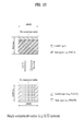
- FIG. 3 illustrates examples of mapping input symbols to subcarriers in the frequency domain while satisfying the single-carrier property. If DFT symbols are allocated to subcarriers according to one of the schemes illustrated in FIGs. 3(a) and 3(b) , a transmission signal satisfying the single-carrier property may be obtained.
- FIG. 3(a) illustrates localized mapping
- FIG. 3(b) illustrates distributed mapping.
- the transmitters 100a and 100b may adopt clustered DFT-spread-OFDM (DFT-s-OFDM).
- DFT-s-OFDM is a modified version of conventional SC-FDMA.
- a signal passing through the DFT/FFT module 307 and the precoder 304 is divided into a predetermined number of sub-blocks and mapped to subcarriers in a non-contiguous manner.
- FIGs. 4 to 6 illustrate examples of mapping an input symbol to a single carrier by clustered DFT-s-OFDM.
- FIG. 4 illustrates a signal processing operation for mapping DFT processed output samples to a single carrier in clustered SC-FDMA.
- FIGs. 5 and 6 illustrate signal processing operations for mapping DFT processed output samples to multiple carriers in clustered SC-FDMA.
- FIG. 4 illustrates the application of intra-carrier clustered SC-FDMA, whereas FIGs. 5 and 6 illustrate the application of inter-carrier clustered SC-FDMA.
- FIG. 5 illustrates signal generation through a single IFFT block in the case where subcarrier spacings between contiguous component subcarriers are aligned in a situation in which component carriers are contiguously allocated in the frequency domain.
- FIG. 6 illustrates signal generation through a plurality of IFFT blocks in a situation in which component carriers are non-contiguously allocated in the frequency domain.
- FIG. 7 illustrates a signal processing operation in segmented SC-FDMA.
- segmented SC-FDMA is a simple extension of the DFT spreading and IFFT subcarrier mapping structure of conventional SC-FDMA and may be expressed as NxSC-FDMA or NxDFT-s-OFDMA.
- segmented SC-FDMA includes all these terms. Referring to FIG. 7 , in segmented SC-FDMA, all modulation symbols in the time domain are divided into N groups (where N is an integer greater than 1) and subjected to a DFT process in units of a group in order to relieve single-carrier property constraints.
- the receivers 300a and 300b operate in the reverse order to the operation of the transmitters 100a and 100b.
- the receivers 300a and 300b decode and demodulate radio signals received through the antennas 500a and 500b from the outside and transfer the demodulated signals to the processors 400a and 400b.
- the antenna 500a or 500b connected to each of the receivers 300a and 300b may include N r reception antennas. A signal received through each reception antenna is restored into a baseband signal and then recovered to the original data stream transmitted by the transmitter 100a or 100b through multiplexing and MIMO demodulation.
- Each of the receivers 300a and 300b may include a signal recoverer for recovering a received signal into a baseband signal, a multiplexer for multiplexing a received and processed signal, and a channel demodulator for demodulating the multiplexed signal stream to a codeword.
- the signal recoverer, the multiplexer, and the channel demodulator may be configured as an integrated module for performing their functions or independent modules.
- the signal recoverer may include an Analog-to-Digital Converter (ADC) for converting an analog signal to a digital signal, a CP remover for removing a CP from the digital signal, an FFT module for generating a frequency-domain symbol by performing FFT on the CP-removed signal, and an RE demapper/equalizer for recovering antenna-specific symbols from the frequency-domain symbol.
- ADC Analog-to-Digital Converter
- the multiplexer recovers transmission layers from the antenna-specific symbols and the channel demodulator recovers the codeword transmitted by the transmitter from the transmission layers.
- each of the receivers 300a and 300b further includes an IFFT module.
- the IDFT/IFFT module IDFT/IFFT-processes the antenna-specific symbols recovered by the RE demapper and outputs the IDFT/IFFT symbol to the multiplexer.
- each of the transmitters 100a and 100b includes the scramblers 301, the modulation mappers 302, the layer mapper 303, the precoder 304, the RE mappers 305, and the OFDM signal generators 306, it may be further contemplated that the scramblers 301, the modulation mappers 302, the layer mapper 303, the precoder 304, the RE mappers 305, and the OFDM signal generators 306 are incorporated into each of the processors 400a and 400b of the transmitters 100a and 100b. Likewise, while it has been described in FIGs.
- each of the receivers 300a and 300b includes the signal recoverer, the multiplexer, and the channel demodulator, it may be further contemplated that the signal recoverer, the multiplexer, and the channel demodulator are incorporated into each of the processors 400a and 400b of the receivers 300a and 300b.
- the scramblers 301, the modulation mappers 302, the layer mapper 303, the precoder 304, the RE mappers 305, and the OFDM signal generators 306 are included in the transmitters 100a and 100b configured separately from the processors 400a and 400b that control operations thereof, and the signal recoverer, the multiplexer, and the channel demodulator are included in the receivers 300a and 300b configured separately from the processors 400a and 400b that control operations thereof.
- embodiments of the present invention are applicable in the same manner even though the scramblers 301, the modulation mappers 302, the layer mapper 303, the precoder 304, the RE mappers 305, and the OFDM generators 306 (and 307) are included in the processors 400a and 400b and the signal recoverer, the multiplexer, and the channel demodulator (in case of the SC-FDMA scheme, the IFFT module is further included) are included in the processors 400a and 400b.
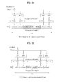
- FIG. 8 illustrates exemplary radio frame structures used in a wireless communication system.
- FIG. 8(a) illustrates a radio frame of Frame Structure type 1 (FS-1) in a 3GPP LTE/LTE-A system
- FIG. 8(b) illustrates a radio frame of Frame Structure type 2 (FS-2) in the 3GPP LTE/LTE-A system.
- the frame structure of FIG. 8(a) may be applied to Frequency Division Duplex (FDD) mode and half-FDD (H-FDD) mode
- the frame structure of FIG. 8(b) may be applied to Time Division Duplex (TDD) mode.
- FDD Frequency Division Duplex
- H-FDD half-FDD
- TDD Time Division Duplex
- a radio frame has a length of 10 ms (307200 Ts) in 3GPP LTE/LTE-A, including 10 equally sized subframes.
- the 10 subframes of the radio frame may be numbered.
- Each subframe is 1ms long, including two slots.
- the 20 slots of the radio frame may be sequentially numbered from 0 to 19.
- Each slot has a length of 0.5 ms.
- a time required to transmit one subframe is defined as a Transmission Time Interval (TTI).
- Time resources may be identified by a radio frame number (or a radio frame index), a subframe number (or a subframe index), and a slot number (or a slot index).
- Different radio frames may be configured according to duplex mode.
- the radio frame includes either downlink subframes or uplink subframes.
- Table 1 shows an exemplary uplink-downlink configuration in TDD mode.
- Uplink-downlink configuration Subframe number 0 1 2 3 4 5 6 7 8 9 0 D S U U U D S U U U 1 D S U U D D S U U D 2 D S U D D D S U D D 3 D S U U U D D D D D 4 D S U U D D D D D D 5 D S U D D D D D D D D 6 D S U U U D S U U U D S U U U D S U U U D S U U D S U U D S U U D
- D denotes a downlink subframe
- U denotes an uplink subframe
- S denotes a special subframe.
- the special subframe includes three fields of a Downlink Pilot Time Slot (DwPTS), a Guard Period (GP), an Uplink Pilot Time Slot (UpPTS).
- DwPTS is a time slot reserved for downlink transmission and UpPTS is a time slot reserved for uplink transmission.
- FIG. 9 illustrates an exemplary downlink/uplink (DL/UL) slot structure in a wireless communication system.
- FIG. 9 illustrates the structure of a resource grid of a 3GPP LTE/LTE-A system. One resource grid exists per antenna port.
- a slot includes a plurality of Orthogonal Frequency Division Multiplexing (OFDM) symbols in a time domain and includes a plurality of Resource Blocks (RBs) in a frequency domain.
- the OFDM symbol may mean one symbol duration.
- An RB includes a plurality of subcarriers in the frequency domain.
- An OFDM symbol may be called an OFDM symbol, an SC-FDM symbol, etc. according to a multiple access scheme.
- the number of OFDM symbols per slot may vary depending on a channel bandwidth and cyclic Prefix (CP) length. For instance, one slot includes 7 OFDM symbols in case of a normal CP, whereas one slot includes 6 OFDM symbols in case of an extended CP. While a subframe is shown in FIG.
- a resource including one OFDM symbol by one subcarrier is referred to as a Reference Element (RE) or a tone.
- RE Reference Element
- a signal transmitted in each slot may be described by a resource grid including N DL/UL RB N RB sc subcarriers and N DL/UL symb OFDM or SC-FDM symbols.
- N DL RB represents the number of RBs in a DL slot
- N UL RB represents the number of RBs in a UL slot.
- N DL RB and N UL RB depend on a DL transmission bandwidth and a UL transmission bandwidth, respectively.
- Each OFDM symbol includes N DL/UL RB N RB sc subcarriers in the frequency domain. The number of subcarriers in one carrier is determined according to FFT magnitude.
- the type of the subcarrier may be divided into a data subcarrier for data transmission, an RS subcarrier for RS transmission, and a null subcarrier for a guard band and a DC component.
- the null subcarrier for the DC component remains unused and is mapped to a carrier frequency f 0 in a process of generating an OFDM signal.
- the carrier frequency is also called a center frequency.
- N DL symb denotes the number of OFDM or SC-FDMA symbols in a DL slot
- N UL symb denotes the number of OFDM or SC-FDMA symbols in a UL slot
- N RB sc denotes the number of subcarriers configuring one RB.
- a Physical Resource Block is defined as N DL/UL symb consecutive OFDM symbols or SC-FDMA symbols in the time domain by N RB sc consecutive subcarriers in the frequency domain. Therefore, one PRB includes N DL/UL symb ⁇ N RB sc REs.
- Each RE in the resource grid may be uniquely identified by an index pair (k, 1) in a slot.
- k is a frequency-domain index ranging from 0 to N DL/UL RB ⁇ N RB sc -1 and 1 is a time-domain index ranging from 0 to N DL/UL symb -1.
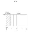
- FIG. 10 illustrates an exemplary DL subframe structure in a wireless communication system.
- each subframe may be divided into a control region and a data region.
- the control region includes one or more OFDM symbols starting from the first OFDM symbol.
- the number of OFDM symbols used in the control region in the subframe may be independently configured in each subframe.
- Information about the number of OFDM symbols is transmitted through a Physical Control Format Indicator Channel (PCFICH).
- PCFICH Physical Control Format Indicator Channel
- a BS may transmit various control information to a UE(s) through the control region.
- a Physical Downlink Control Channel (PDCCH), a PCFICH, and a Physical Hybrid automatic repeat request Indicator Channel (PHICH) may be allocated to the control region.
- PDCCH Physical Downlink Control Channel
- PCFICH Physical Hybrid automatic repeat request Indicator Channel
- the BS transmits information associated with resource allocation of a Paging Channel (PCH) and a Downlink-Shared Channel (DL-SCH) which are transport channels, a UL scheduling grant, Hybrid Automatic Repeat Request (HARQ) information, a Downlink Assignment Index (DAI), etc. to each UE or UE group on the PDCCH.
- PCH Paging Channel
- DL-SCH Downlink-Shared Channel
- HARQ Hybrid Automatic Repeat Request
- DAI Downlink Assignment Index
- the BS may transmit data for UEs or UE groups through the data region.
- Data transmitted through the data region is also referred to as user data.
- a Physical Downlink Shared Channel (PDSCH) may be allocated to the data region.
- the PCH and DL-SCH are transmitted through the PDSCH.
- the UE may read data transmitted through the PDSCH by decoding control information transmitted through the PDCCH.
- Information indicating to which UE or UE group PDSCH data is transmitted and information indicating how the UE or UE group should receive and decode the PDSCH data are transmitted over the PDCCH.
- a specific PDCCH is CRC-masked with a Radio Network Temporary Identity (RNTI) 'A' and information about data transmitted using a radio resource 'B' (e.g. frequency location) and using transport format information 'C' (e.g. transmission block size, modulation scheme, coding information, etc.) is transmitted through a specific subframe.
- RNTI Radio Network Temporary Identity
- transport format information 'C' e.g. transmission block size, modulation scheme, coding information, etc.
- a plurality of PDCCHs may be transmitted in the control region.
- a UE may monitor the plurality of PDCCHs to detect a PDCCH thereof.
- Downlink Control Information (DCI) carried by the PDCCH may be different in size and purpose according to a DCI format and in size according to coding rate.
- the DCI format may be independently applied for each UE, and the PDCCHs of multiple UEs may be multiplexed in one subframe.
- the PDCCH of each UE may be independently channel-coded so that a Cyclic Redundancy Check (CRC) can be added to the PDCCH.
- CRC Cyclic Redundancy Check
- the CRC is masked with a unique identifier of each UE so that each UE can receive the PDCCH thereof.
- the UE is required to perform blind detection (also referred to as blind decoding) on all PDCCHs of the corresponding DCI format in every subframe, until the PDCCH having the identifier thereof is received.
- FIG. 11 illustrates an exemplary UL subframe structure in a wireless communication system
- a UL subframe may be divided into a control region and a data region in the frequency domain.
- One or multiple Physical Uplink Control Channels may be allocated to the control region to carry Uplink Control Information (UCI).
- One or multiple Physical Uplink Shared Channels (PUSCHs) may be allocated to the data region to carry user data. If the UE adopts an SC-FDMA scheme for uplink transmission, the PUCCH and the PUSCH cannot be simultaneously transmitted in order to maintain a single-carrier property.
- the UCI carried by the PUCCH may be different in size and purpose according to a PUCCH format and in size according to coding rate.
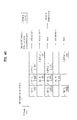
- the PUCCH format may be defined as follows. [Table 2] PUCCH format Modulation scheme Number of bits per subframe Usage Etc.
- SR Switching Request
- 1a BPSK 1 ACK/NACK or SR + ACK/NACK
- One codeword 1b QPSK 2 ACK/NACK or SR + ACK/NACK
- Two codeword 2 QPSK 20 CQI/PMI/RI Joint coding ACK/NACK (extended CP) 2a QPSK+BPSK 21 CQI/PMI/RI + ACK/NACK Normal CP only 2b QPSK+QPSK 22 CQI/PMI/RI + ACK/NACK Normal CP only 3 QPSK 48 ACK/NACK or SR + ACK/NACK or CQI/PMI/RI + ACK/NACK
- subcarriers distant from a Direct Current (DC) subcarrier are used as the control region.
- DC subcarriers located at both ends of a UL transmission bandwidth are assigned for UL control information transmission.
- DC subcarriers are reserved without being used in signal transmission and are mapped to a carrier frequency f 0 in a frequency up-conversion process caused by the OFDM/SC-FDMA signal generator 306.
- a PUCCH for a UE is allocated to an RB pair in a subframe.
- the RBs of the RB pair occupy different subcarriers in two slots. This is called frequency hopping of an RB pair allocated to a PUCCH over a slot boundary. However, if frequency hopping is not used, an RB pair occupies the same subcarriers. Irrespective of the frequency hopping, a PUCCH for one UE is assigned to an RB pair in one subframe and therefore the same PUCCH is transmitted once through one RB in each slot, a total of two times, in one UL subframe.
- an RB pair used for each PUCCH transmission of one subframe is called a PUCCH region or a PUCCH resource.
- a PUCCH carrying Acknowledgement/Negative Acknowledgement (ACK/NACK) is referred to as an ACK/NACK PUCCH
- a PUCCH carrying Channel Quality Indicator (CQI)/Precoding Matrix Indicator (PMI)/Rank Information (RI) is referred to as a Channel State Information (CSI) PUCCH
- CSI Channel State Information
- SR Scheduling Request
- the UE is assigned PUCCH resources for UCI transmission from the BS according to the explicit or implicit scheme.
- UCI such as ACK/NACK, CQI, PMI, RI, SR, etc. may be transmitted over a control region of the UL subframe.
- the BS and the UE mutually transmit/receive signals or data. If the BS/UE transmits data to the UE/BS, the UE/BS decodes the received data. If the data is successfully decoded, ACK is transmitted to the BS/UE. If data decoding fails, NACK is transmitted to the BS/UE.
- the UE receives a data unit (e.g., PDSCH) from the BS and transmits ACK/NACK to the data unit to the BS through implicit PUCCH resources decided by PDCCH resources carrying scheduling information for the data unit.
- a data unit e.g., PDSCH
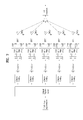
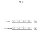
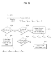
- FIG. 12 illustrates an example for determining PUCCH resources for ACK/NACK.
- a PUCCH resource for ACK/NACK is not previously allocated to each UE and multiple UEs located in a cell use a plurality of PUCCH resources in a divided manner at every time point.
- the PUCCH resource used for ACK/NACK transmission of the UE is implicitly determined based on a PDCCH that carries scheduling information of a PDSCH that carries corresponding DL data.
- An entire region in which a PDCCH is transmitted in a DL subframe includes a plurality of Control Channel Elements (CCEs) and a PDCCH transmitted to the UE includes one or more CCEs.
- Each CCE includes a plurality of Resource Element Groups (REGs) (e.g. 9 REGs).
- One REG is comprised of four contiguous REs when a Reference Signal (RS) is excluded.
- the UE transmits ACK/NACK through an implicit PUCCH resource that is derived or calculated using a function of a specific CCE index (e.g. the first or lowest CCE index) from among indexes of CCEs that constitute the PDCCH received by the UE.
- a specific CCE index e.g. the first or lowest CCE index
- each PUCCH resource index corresponds to a PUCCH resource for ACK/NACK.
- PDSCH scheduling information is transmitted to the UE through a PDCCH consisting of CCEs numbered 4 to 6
- the UE transmits ACK/NACK to the BS through a PUCCH derived or calculated from CCE number 4, which is the lowest CCE of the PDCCH, for example, through PUCCH number 4.
- FIG. 12 shows an example in which up to M'CCEs are present in a DL subframe and up to M PUCCH resources are present in a UL subframe.
- M' may be equal to M, M' may be different from M and CCEs and PUCCH resources may be mapped in an overlapping manner.
- n (1) PUCCH is a PUCCH resource index for ACK/NACK transmission
- N (1) PUCCH is a signaling value received from a higher layer
- n CCE denotes the lowest CCE index used for PDCCH transmission.
- FIG. 13 illustrates exemplary communication in a single carrier situation.
- FIG. 13 may correspond to an example of communication in the LTE system.
- a general FDD wireless communication system transmits and receives data through one DL band and one UL band corresponding to the DL band.
- a BS and a UE transmit and receive data and/or control information scheduled in a subframe unit.
- the data is transmitted and received through a data region configured in UL/DL subframes and the control information is transmitted and received through a control region configured in the UL/DL subframes.
- the UL/DL subframes carry signals on various physical channels.
- FIG. 14 illustrates exemplary communication in a multi-carrier situation.
- the LTE-A system uses carrier aggregation or bandwidth aggregation that uses a wider UL/DL bandwidth by aggregating a plurality of UL/DL frequency blocks in order to employ a wider frequency band.
- a multicarrier system or Carrier Aggregation (CA) system refers to a system aggregating a plurality of carriers each having a narrower bandwidth than a target bandwidth, for broadband support.
- CA Carrier Aggregation
- the bandwidth of the aggregated carriers may be limited to a bandwidth used in a legacy system in order to maintain backward compatibility with the legacy system.
- an LTE system may support bandwidths of 1.4, 3, 5, 10, 15, and 20MHz and the LTE-Advanced (LTE-A) system improved from the LTE system may support bandwidths wider than 20MHz using the bandwidths supported in the LTE system.
- LTE-A LTE-Advanced
- a new bandwidth may be defined to support CA irrespective of bandwidth used in the legacy system.
- the term multicarrier is used interchangeably with the terms CA and bandwidth aggregation. Contiguous CA and non-contiguous CA are collectively referred to as CA.
- CA Component Carrier
- a UL CC and a DL CC are also referred to as UL resources and DL resources, respectively.
- each of 20MHz may be aggregated on each of UL and DL to support a bandwidth of 100MHz.
- the respective CCs may be contiguous or non-contiguous in the frequency domain.
- FIG. 14 shows the case in which the bandwidth of a UL CC is the same as the bandwidth of a DL CC and the two are symmetrical.
- the bandwidth of each CC may be independently determined.
- the bandwidth of the UL CC may be configured in a manner of 5MHz (UL CC0) + 20MHz (UL CC1) + 20MHz (UL CC2) + 20MHz (UL CC3) + 5MHz (UL CC4).
- Asymmetric CA may be generated due to limitation of available frequency bands or may be intentionally formed by network configuration. For example, even when the BS manages X DL CCs, a frequency band which can be received by a specific UE may be limited to Y ( ⁇ X) DL CCs. In this case, the UE needs to monitor DL signals/data transmitted through the Y CCs. In addition, even when the BS manages L UL CCs, a frequency band which can be received by a specific UE may be limited to M ( ⁇ L) UL CCs.
- the limited DL CCs or UL CCs for a specific UE are referred to as serving UL or DL CCs configured in a specific UE.
- the BS may allocate a prescribed number of CCs to the UE by activating some or all of the CCs managed by the BS or by deactivating some CCs managed by the BS.
- the BS may change the activated/deactivated CCs and change the number of activated/deactivated CCs.
- the BS may cell-specifically or UE-specifically configure Z DL CCs (where 1 ⁇ Z ⁇ Y ⁇ X) that the UE should first monitor/receive as main DL CCs.
- the BS may cell-specifically or UE-specifically configure N UL CCs (where 1 ⁇ N ⁇ M ⁇ L) that the UE should first transmit as main UL CCs.
- the restricted main DL or UL CCs for a specific UE are also referred to as serving UL or DL CCs configured in a specific UE.
- Various parameters for CA may be configured cell-specifically, UE group-specifically, or UE-specifically.
- the BS allocates available CCs to the UE cell-specifically or UE-specifically, at least one of the allocated CCs is not deactivated, unless overall CC allocation to the UE is reconfigured or the UE is handed over.
- the CC which is not deactivated unless the overall CC allocation to the UE is reconfigured is referred to as a Primary CC (PCC) and a CC that the BS can freely activate/deactivate is referred to as a Secondary CC (SCC).
- PCC Primary CC
- SCC Secondary CC
- Single carrier communication uses one PCC for communication between the UE and the BS and does not use the SCC for communication. Meanwhile, the PCC and SCC may also be distinguished based on control information.
- control information may be set to be transmitted/received only through a specific CC.
- a specific CC may be referred to as a PCC and the other CC(s) may be referred to as SCC(s).
- control information transmitted through a PUCCH may correspond to such specific control information.
- a UL CC in which the PUCCH of the UE is present may be referred to as a UL PCC and the other UL CC(s) may be referred to as UL SCC(s).
- the specific UE may receive a DL Synchronization Signal (SS) from the BS as specific control information.
- SS DL Synchronization Signal
- a DL CC with which the specific UE establishes synchronization of initial DL time by receiving the DL SS i.e. a DL CC used for attempting to access a network of the BS
- DL PCC a DL CC with which the specific UE establishes synchronization of initial DL time by receiving the DL SS
- the other DL CC(s) may be referred to as DL SCC(s).
- multicarrier communication uses one PCC and no SCC or one or more SCC(s) per UE.
- the PCC may be referred to as a primary CC, an anchor CC, or a primary carrier and the SCC may be referred to as a secondary CC or a secondary carrier.
- LTE-A uses the concept of cells to manage radio resources.
- a cell is defined as a combination of DL resources and UL resources, that is, a DL CC and a UL CC.
- the UL resources are not an indispensible component. However, this is defined in the current LTE-A standard and, in the future, it may be permitted that a cell is configured using the UL resources alone. Accordingly, the cell can be configured with the DL resources alone, or with both the DL resources and UL resources.
- linkage between carrier frequency of the DL resources (or DL CC) and carrier frequency of the UL resources (or UL CC) may be indicated by system information.
- a combination of the DL resources and the UL resources may be indicated by a System Information Block type 2 (SIB2).
- SIB2 System Information Block type 2
- the carrier frequency refers to a center frequency of each cell or CC.
- a cell that operates on a primary frequency (or PCC) may be referred to as a Primary Cell (PCell) and a cell(s) that operates on a secondary frequency (or SCC) may be referred to as a Secondary Cell(s) (SCell(s)).
- the primary frequency (or PCC) refers to a frequency (or CC) used for the UE to perform an initial connection establishment or connection reestablishment procedure.
- PCell may refer to a cell indicated during a handover process.
- the secondary frequency refers to a frequency (or CC) that is configurable after RRC connection setup is performed and is usable to provide additional radio resources.
- the PCell and SCell may be collectively referred to as a serving cell. Accordingly, for a UE that is in an RRC_CONNECTED state, for which CA is not configured or CA is not supported, only one serving cell comprised of only the PCell is present. Meanwhile, for a UE in an RRC_CONNECTED state, for which CA is configured, one or more serving cells may be present and all serving cells may include one PCell and one or more SCells. However, in the future, it may be permitted that the serving cell includes a plurality of PCells.
- a network may configure one or more SCells for a UE that supports CA in addition to the PCell initially configured in the connection establishment procedure after an initial security activation procedure is initiated. However, even if the UE supports CA, the network may configure only the PCell for the UE, without adding the SCells.
- the PCell may be referred to as a primary CC, an anchor CC, or a primary carrier and the SCell may be referred to as a secondary CC or a secondary carrier.
- the BS may transmit a plurality of data units to the UE in a given cell(s) (or CC(s)) and the UE may transmit ACK/NACK signals for the plurality of data units in one subframe.
- the UE may be allocated one or plural cells (or DL CCs) for receiving a PDSCH for DL data reception.
- a cell (or DL CC(s)) for the UE may be semi-statically configured or reconfigured by RRC signaling.
- a cell (or DL CC(s)) for the UE may be dynamically activated/deactivated by L1/L2 (Medium Access Control (MAC)) control signaling.
- L1/L2 Medium Access Control
- the maximum number of ACK/NACK bits to be transmitted by the UE varies according to cells (or DL CCs) available to the UE. That is, the maximum number of ACK/NACK bits to be transmitted by the UE is configured/reconfigured by RRC or varies with an activated DL CC (or configured serving cell(s)) by L1/L2 signaling.
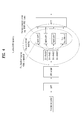
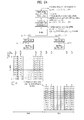
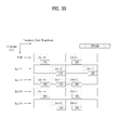
- FIG. 15 explains a concept that one MAC layer manages multiple carriers in a BS.
- FIG. 16 explains a concept that one MAC layer manages multiple carriers in a UE.
- one MAC layer manages one or more frequency carriers so as to perform transmission and reception. Since the frequency carriers managed by one MAC layer need not be contiguous, more flexible resource management is possible.
- one physical layer PHY means one CC for convenience.
- one PHY does not necessarily mean an independent Radio Frequency (RF) device.
- RF Radio Frequency
- one independent RF device means one PHY but is not limited thereto.
- One RF device may include several PHYs.
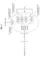
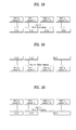
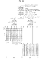
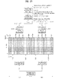
- FIG. 17 explains a concept that a plurality of MAC layers manages multiple carriers in a BS and FIG. 18 explains a concept that a plurality of MAC layers manages multiple carriers in a UE.
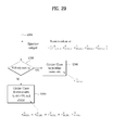
- FIG. 19 explains another concept that a plurality of MAC layers manages multiple carriers in a BS and FIG. 20 explains another concept that a plurality of MAC layers manages multiple carriers in a UE.
- multiple MAC layers may control a plurality of CCs as shown in FIGs. 17 to 20 .
- each MAC layer may control each carrier in one-to-one correspondence.
- each MAC layer may control each carrier in one-to-one correspondence with respect to partial carriers and one MAC layer may control one or more carriers with respect to the other carriers.
- the system applied to the above description is a system supporting one carrier to N multiple carriers and carriers may be contiguous or non-contiguous carriers, regardless of UL/DL.
- a TDD system is configured to manage N carriers each including DL and UL transmission and an FDD system is configured to respectively use multiple carriers in UL and DL.
- the FDD system may support asymmetric CA in which the numbers of aggregated carriers and/or the bandwidths of carriers in UL and DL are different.
- CCs aggregated in UL is equal to the number of CCs aggregated in DL, it is possible to configure CCs such that all CCs are compatible with CCs used in a legacy system. However, CCs that do not support compatibility are not excluded from the present invention.
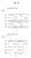
- FIGs. 21 and 22 illustrate slot level structures of PUCCH formats 1a and 1b for ACK/NACK transmission.
- FIG. 21 illustrates PUCCH formats 1a and 1b in case of normal CP and FIG. 22 illustrates PUCCH formats 1a and 1b in case of extended CP.
- the same control information is repeated on a slot basis in a subframe in PUCCH formats 1a and 1b
- a UE transmits ACK/NACK signals through different resources of different Cyclic Shifts (CSs) (frequency-domain codes) and Orthogonal Cover (OC) or Orthogonal Cover Codec (OCCc) (time-domain spreading codec) of a Computer-Generated Constant Amplitude Zero Auto Correlation (CG-CAZAC) sequence.
- An OC includes, for example, a Walsh/DFT orthogonal code.
- a total of 18 UEs may be multiplexed in the same Physical Resource Block (PRB) based on a single antenna.
- PRB Physical Resource Block
- Orthogonal sequences w0, w1, w2, and w3 are applied in an arbitrary time domain (after FFT modulation) or in an arbitrary frequency domain (before FFT modulation).
- PUCCH format 1 for SR transmission and PUCCH formats 1a and 1b are the same in slot level structure and different in modulation scheme.
- PUCCH resources comprised of a CS, an OC, and a PRB may be allocated to a UE by Radio Resource Control (RRC) signaling, for SR transmission and for ACK/NACK feedback for Semi-Persistent Scheduling (SPS).
- RRC Radio Resource Control
- SPS Semi-Persistent Scheduling
- a PUCCH resource may be implicitly allocated to a UE using the lowest CCE index of a PDCCH corresponding to a PDSCH or a PDCCH for SPS release.
- FIG. 23 illustrates a scenario of transmitting UCI in a wireless communication system supporting CA.
- UCI is ACK/NACK (A/N).
- UCI may include control information such as CSI (e.g. CQI, PMI, and RI) and scheduling request information (e.g. SR), without restriction.
- CSI e.g. CQI, PMI, and RI
- scheduling request information e.g. SR
- FIG. 23 illustrates exemplary asymmetrical CA in which five DL CCs are linked to a single UL CC.
- This asymmetrical CA may be set from the perspective of transmitting UCI. That is, DL CC-UL CC linkage for UCI may be set to be different from DL CC-UL CC linkage for data. For convenience, if it is assumed that each DL CC can carry up to two codewords and the number of ACKs/NACKs for each CC depends on the maximum number of codewords set per CC (e.g.
- ACKs/NACKs for the CC are set to 2 which is the maximum number of codewords on the CC
- at least two UL ACK/NACK bits are needed for each DL CC.
- at least 10 ACK/NACK bits are needed to transmit ACKs/NACKs to data received on five DL CCs on a single UL CC.
- DTX Discontinuous Transmission
- this structure cannot transmit increased ACK/NACK information.
- CA is given as an example of a cause to increase the amount of UCI
- this situation may also occur due to an increase in the number of antennas and existence of a backhaul subframe in a TDD system and a relay system.
- the amount of control information to be transmitted is also increased when control information related to a plurality of DL CCs is transmitted on a single UL CC. For example, transmission of CQI/PMI/RI information related to a plurality of DL CCs may increase UCI payload.
- a UL anchor CC (also referred to as a UL PCC or a UL primary CC) is a CC on which a PUCCH or UCI is transmitted and may be cell-specifically/UE-specifically determined.
- a DTX state may be explicitly fed back or may be fed back so as to share the same state as NACK.
- the new PUCCH format proposed by the present invention is referred to as a CA PUCCH format, or PUCCH format 3 relative to PUCCH format 2 defined in legacy LTE Release 8/9.
- the technical features of the proposed PUCCH format may be easily applied to any physical channel (e.g. a PUSCH) that can deliver UCI in the same manner or in a similar manner.
- a PUSCH physical channel
- an embodiment of the present invention is applicable to a periodic PUSCH structure for periodically transmitting control information or an aperiodic PUSCH structure for aperiodically transmitting control information.
- the following drawings and embodiment of the present invention will be described, focusing on the case of using the UCI/RS symbol structure of PUCCH formats 1/1a/1b (a normal CP) of legacy LTE as a subframe/slot level UCI/RS symbol structure applied to PUCCH format 3.
- the subframe/slot level UCI/RS symbol structure of PUCCH format 3 is exemplarily defined for convenience and the present invention is not limited to such a specific structure.
- the number and positions of UCI/RS symbols may be changed freely in PUCCH format 3 of the present invention according to system design.
- PUCCH format 3 according to an embodiment of the present invention may be defined using the RS symbol structure of PUCCH formats 2/2a/2b of legacy LTE.
- PUCCH format 3 may be used to transmit UCI of any type or size.
- information such as HARQ ACK/NACK, a CQI, a PMI, an RI, and an SR may be transmitted in PUCCH format 3 according to the embodiment of the present invention may.
- This information may have a payload of any size.
- the following description will focus on transmission of ACK/NACK information in PUCCH format 3 according to the present invention.
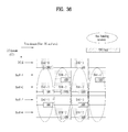
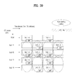
- FIGs. 24 to 27 illustrate a PUCCH format structure for feeding back a plurality of ACK/NACK bits and a signal processing operation therefor.
- the PUCCH format may be used when a plurality ACK/NACK bits is fed back in a multi-carrier environment.
- Such a PUCCH format may be referred to as PUCCH format 3 to distinguish it from a conventional series of PUCCH formats 1 and 2.
- FIGs. 24 to 27 illustrate a DFT-based PUCCH format structure.
- a PUCCH is DFT-precoded and a time-domain OC is applied thereto at an SC-FDMA level prior to transmission.
- the DFT-based PUCCH format will be referred to as PUCCH format 3.
- a channel coding block channel-encodes information bits a_0, a_1, . . .,a_M-1 (e.g. multiple ACK/NACK bits) and generates coded bits (or a codeword), b_0, b_1, . . .,b_N-1.
- M is the size of information bits
- N is the size of coded bits.
- the information bits include UCI, for example, multiple ACKs/NACKs to a plurality of data (or PDSCHs) received on a plurality of DL CCs.
- the information bits a_0, a_1, . . .,a_M-1 are jointly encoded irrespective of the type/number/size of UCI constituting the information bits.
- the information bits include multiple ACKs/NACKs for a plurality of DL CCs
- channel coding is performed on the entire bit information, rather than per DL CC or per individual ACK/NACK bit.
- a single codeword is generated by channel coding.
- Channel coding includes, but is not limited to, repetition, simplex coding, Reed Muller (RM) coding, punctured RM coding, Tail-Biting Convolutional Coding (TBCC), Low-Density Parity-Check (LDPC) coding, or turbo coding.
- RM Reed Muller
- TBCC Tail-Biting Convolutional Coding
- LDPC Low-Density Parity-Check
- the coded bits may be rate-matched, in consideration of modulation order and the amount of resources.
- the rate matching function may be partially incorporated into the channel coding block or implemented in a separate functional block.
- the channel coding block may obtain a single codeword by performing (32, 0) RM coding with respect to a plurality of control information and may perform cyclic buffer rate-matching.
- a modulator generates modulation symbols c_0, c_1, . . .,c_L-1 by modulating the coded bits b_0, b_1, . . .,b_M-1.
- L is the size of modulation symbols.
- a modulation scheme is performed by changing the amplitude and phase of a transmission signal.
- the modulation scheme includes, for example, n-Phase Shift Keying (n-PSK) and n-Quadrature Amplitude Modulation (QAM) (where n is an integer of 2 or more).
- the modulation scheme includes Binary PSK (BPSK), Quadrature PSK (QPSK), 8-PSK, QAM, 16-QAM, or 64-QAM.
- a divider divides the modulation symbols c_0, c_1, . . .,c_L-1 into slots.
- the order/pattern/scheme of dividing modulation symbols into slots is not limited to a specific one.
- the divider may divide the modulation symbols into slots, sequentially starting from the first modulation symbol (localized scheme).
- the modulation symbols c_0, c_1, . . .,c_L/2-1 may be allocated to slot 0 and the modulation symbols c_L/2, c_L/2+1, . . .,c_L-1 may be allocated to slot 1.
- the modulation symbols may be interleaved (or permuted). For example, even-numbered modulation symbols may be allocated to slot 0 and odd-numbered modulation symbols may be allocated to slot 1.
- the modulation process and the division process are interchangeable in order.
- a DFT precoder performs DFT precoding (e.g. 12-point DFT) with respect to the modulation symbols divided into the slots in order to generate a single carrier waveform.
- DFT precoding e.g. 12-point DFT
- the modulation symbols c_0, c_1, . . .,c_L/2-1 allocated to slot 0 are DFT-precoded to DFT symbols d_0, d_1, . . .,d_L/2-1
- the modulation symbols c_L/2, c_L/2+1, . . .,c_L-1 allocated to slot 1 are DFT-precoded to DFT symbols d_L/2, d_L/2+1, . . .,d_L-1.
- DFT precoding may be replaced with another linear operation (e.g. Walsh precoding).
- a spreading block spreads the DFT-precoded signals at an SC-FDMA symbol level (in the time domain).
- Time-domain spreading at the SC-FDMA symbol level is performed using a spreading code (sequence).
- the spreading code includes a quasi-orthogonal code and an orthogonal code.
- the quasi-orthogonal code includes, but is not limited to, a Pseudo Noise (PN) code.
- the orthogonal code includes, but is not limited to, a Walsh code and a DFT code. While the orthogonal code is described as a typical example of the spreading code for convenience of description, the orthogonal code may be replaced with the quasi-orthogonal code.
- the maximum value of a spreading code size or an SF is limited by the number of SC-FDMA symbols used for transmission of control information. For example, if four SC-FDMA symbols are used for control information transmission in one slot, an orthogonal code of length 4, w0, w1, w2, and w3 can be used in each slot.
- the SF means the degree of spreading of control information and may be related to the multiplexing order or antenna multiplexing order of a UE.
- the SF may be changed to 1, 2, 3, 4, . . . depending on system requirements.
- the SF may be predefined between a BS and a UE or the BS may indicate an SF to the UE by DCI or RRC signaling.
- a signal generated from the above operation is mapped to subcarriers in a PRB and converted into a time-domain signal by IFFT.
- a CP is added to the time-domain signal and the generated SC-FDMA symbols are transmitted through an RF end.
- ACK/NACK bits for the PDSCHs may be 12 bits, including a DTX state.
- the size of a coding block (after rate matching) may be 48 bits.
- the coded bits are modulated to 24 QPSK symbols and the QPSK symbols are divided into two slots each including 12 QPSK symbols.
- the 12 QPSK symbols in each slot are converted into 12 DFT symbols by 12-point DFT.
- the basic signal processing operation is performed in the same manner as described with reference to FIG. 25 except for the number and positions of UCI SC-FDMA symbols and RS SC-FDMA symbols.
- a spreading block may be applied in advance at the front end of the DFT precoder.
- RSs may use the same structure as those used in the LTE system.
- a base sequence may be cyclically shifted.
- the multiplexing capacity of an RS part is determined by a CS interval ⁇ shift PUCCH .
- the multiplexing capacity may be 12/ ⁇ shift PUCCH .
- the multiplexing capacity of the RS part is 4 in case of ⁇ shift PUCCH . Therefore, overall multiplexing capacity may be limited to the smaller of the two values, 4.
- FIG. 26 illustrates an exemplary structure of PUCCH format 3 that can increase a multiplexing capacity at a slot level.
- Overall multiplexing capacity can be increased by applying SC-FDMA symbol-level spreading described with reference to FIGs. 24 and 25 to RSs.
- the multiplexing capacity is doubled by applying a Walsh cover (or a DFT code cover) within a slot. Then, the multiplexing capacity is 8 even in case of ⁇ shift PUCCH , thereby preventing the multiplexing capacity of a data part from decreasing.
- [y1 y2] [1 1]
- [y1 y2] [1 -1]
- a linear transform thereof e.g. [j j] [j -j], [1 j] [1 -j], etc.
- FIG. 27 illustrates an exemplary PUCCH format 3 structure that can increase multiplexing capacity at a subframe level.
- the multiplexing capacity is doubled again by applying a Walsh cover in units of a slot.
- PUCCH format 3 is not limited to the orders illustrated in FIGs. 24 to 27 .
- Channel selection refers to expression/transmission of specific information by selecting a specific resource from among a plurality of resources.
- General channel selection is a scheme of transmitting specific information by a combination of a resource and constellation.
- the resource may be specified by a physical time-frequency resource and/or a sequence resource (e.g. a CS value).
- a specific resource may be selected by a combination of an OC, a CS, and a Physical Resource Unit (PRU).
- PRU Physical Resource Unit
- a channel selection method shown in the following Table 3 may be used. [Table 3] Ch1 Ch2 RS Data RS Data ACK a b 0 0 NACK 0 0 a b
- the values expressed as a, b, c,... may be values multiplexed, scrambled, or covered by an allocated sequence or an allocated code, rather than the constellation values.
- the values expressed as a, b, c,... with respect to Ch-x may be values capable of distinguishing therebetween and a method for distinguishing between the values is not restricted.
- the values expressed as a, b, c,... with respect to Ch-x are referred to as modulated values, for convenience of description.
- a, b, c,... may be predetermined specific values rather than 0.
- a may be '+1' and b may be '-1'.
- ACK ACK
- NACK NACK
- a value a is transmitted in an RS part of resource 1 (i.e. Ch1) and a value b is transmitted in a data part of resource 1.
- a value b is transmitted in an RS part of resource 2 (i.e. Ch2) and b is transmitted in a data part of resource 2.
- channel selection a method for transmitting different information depending on through which resource a signal is transmitted.
- Table 4 shows an example using two types of distinguishable constellation mapping (e.g. BPSK).
- a, b, and c may be specific values other than 0. Notably, it is preferable that b and c be distant from each other on constellation.
- a may be used as '+1' and b and c may be used as '+1' and '-1', respectively or '-1' and '+1', respectively.
- a value modulated to b is transmitted in resource 1 (Ch1) for ACK/ACK transmission and a value modulated c is transmitted in resource 1 (Ch1) for ACK/NACK transmission.
- a value modulated to b is transmitted in resource 2 (Ch2) for NACK/ACK transmission and a value modulated to c is transmitted in resource 2 (Ch2) for NACK/NACK.
- TDD ACK/NACK multiplexing may have the same meaning as TDD ACK/NACK channel selection but they have different meanings in a multicarrier support system (e.g. LTE-A or LTE-release-10) which will be described later.
- a value M may be determined by a DL related set index K: ⁇ k 0 ,k 1 , ⁇ k M -1 ⁇ (defined as in Table 12 which will be described later) in a TDD system.
- K a DL related set index
- two PUCCH resources n PUCCH , 0 1 and n PUCCH , 1 1 and a QPSK constellation ' b (0), b (1)' in each PUCCH resource may be used to transmit two types of ACK/NACK information including spatial bundling (i.e. ACK/NACK bundling for a plurality of codewords).
- the UE transmits bits ' b (0), b (1)' on an ACK/NACK resource n PUCCH 1 using PUCCH format 1b in subframe n.
- HARQ-ACK(i) indicates a HARQ ACK/NACK/DTX result for an i-th data unit (0 ⁇ i ⁇ 3).
- DTX means that there is no data unit transmitted for corresponding HARQ-ACK(i) or the data unit corresponding to HARQ-ACK(i) has not been detected by the UE.
- HARQ-ACK is used interchangeably with ACK/NACK.
- a maximum of four PUCCH resources i.e. n (1) PUCCH,0 to n (1) PUCCH,3 ) may be occupied for each data unit. Multiplexed ACK/NACK signals are transmitted through one PUCCH resource selected from among the occupied PUCCH resources.
- n (1) PUCCH,x indicates a PUCCH resource used for actual ACK/NACK transmission
- 'b(0)b(1)' indicates two bits transmitted through the selected PUCCH resource, which is modulated using QPSK. For example, if the UE successfully decodes four data units as in Table 7, the UE transmits (1, 1) to the BS through a PUCCH resource connected to n (1) PUCCH,1 . Since combinations of PUCCH resources and QPSK symbols cannot represent all of available ACK/NACK, NACK and DTX are coupled (expressed as NACK/DTX) except in some cases.
- a channel selection mapping relationship which is used to apply the channel selection method.
- a channel selection mapping relationship for transmitting ACK/NACK information as shown in Tables 8 to 10 may be defined.
- Table 8 defines a mapping relationship for 2-bit ACK/NACK
- Table 9 defines mapping relationship for 3-bit ACK/NACK
- Table 10 defines a mapping relationship for 4-bit ACK/NACK.
- channel mapping relationships for 1-bit to 4-bit ACK/NACK as shown in Table 11 may be defined.
- b0 may be generated and transmitted for 1-bit ACK/NACK information
- b0 and b1 may be generated and transmitted for 2-bit ACK/NACK information
- b0, b1, and b2 may be generated and transmitted for 3-bit ACK/NACK information
- b0, b1, b2, and b3 may be generated and transmitted for 4-bit ACK/NACK information.
- DL resources may be defined as a DL CC and UL resources may be defined as a UL CC.
- a combination of DL resources and UL resources may be referred to as a cell.
- the cell may refer to only the DL CCs (or UL CCs). For example, if a specific UE is configured with one serving cell, one DL CC and one UL CC are present. However, if a specific UE is configured with two or more serving cells, DL CCs which is equals in number to the cells and UL CCs which is equal to or less than the DL CCs in number are present.
- a multicarrier environment in which the number of UL CCs is greater than the number of DL CCs may be supported.
- Linkage between carrier frequencies (center frequencies of a cell) of the DL and UL resources may be indicated by system information transmitted on the DL resources.
- a combination of the DL resources and the UL resources may be configured by linkage defined by an SIB2.
- CA may refer to an aggregate of two or more cells having different carrier frequencies. That is, the case in which a specific UE is configured with two or more serving cells having different carrier frequencies may be referred to as a CA environment.
- one or more SCells may be aggregated with a PCell to support increased bandwidth.
- the serving cell may be a PCell or an SCell.
- serving cells refer to a set of one or more cells including a PCell and SCells.
- the PCell is a central cell of control related communication among serving cells configured in a CA environment.
- the PCell is a cell indicated or used by a UE in an initial connection establishment procedure, a connection re-establishment procedure, or a handover procedure.
- the UE may receive and transmit a PUCCH only on the PCell thereof.
- the UE may perform a monitoring procedure for system information acquisition and change only on the PCell.
- a BS may change only through a handover procedure using an RRCConnectionReconfiguration message including mobilityControlInfo.
- SCells refer to cells except for the PCell among serving cells configured in a CA environment. No PUCCHs are present on the SCell.
- the BS may provide all system information related to an operation on the SCell of an RRC_CONNECTED state to the UE supporting CA through dedicated signaling. For the SCell, change in system information may be performed by release and addition of the SCell through one RRCConnectionReconfiguration message.
- the BS may transmit dedicated signaling having a different parameter from a parameter included in a broadcast message on the SCell to the UE.
- the BS may configure one or more SCells in addition to the PCell (a cell configured as a serving cell during a connection establishment procedure) for the UE.
- the PCell may be used to provide security input and higher-layer system information and the SCell may be used to provide additional DL resources and, when necessary, UL resources.
- the BS may independently add, eliminate, or correct the SCell through an RRC reconnection reconfiguration procedure using an RRCConnectionReconfiguration message which includes or does not include mobilityControlInfo.
- PhyCellId may have an integer ranging from 0 to 503 and may be used as a physical layer identifier of a cell.
- SCellIndex may have an integer ranging from 1 to 7 and may be used as an identifier of an SCell.
- ServCellIndex may have an integer ranging from 0 to 7 and may be used as an identifier of a serving cell (PCell or SCell).
- PCell or SCell serving cell
- ServCellIndex having a value of 0 may be applied to the PCell and, for the SCell, SCellIndex may be applied. That is, a cell having the smallest (or lowest) cell index in ServCellIndex may be defined as the PCell.
- multiple carriers in CA are divided into a PCell and an SCell which are UE-specific parameters.
- a specific UE may have one or more configured serving cells. If a plurality of configured serving cells is present, one of the serving cells is a PCell and the other cells are SCells. If the UE has a plurality of configured serving cells in TDD, UL-DL configurations indicating which UL subframe is used to transmit ACK/NACK for a PDSCH transmitted in a specific DL subframe may be equal in all cells.
- the UE may transmit UCI such as CSI (including CQI, RI, PMI, etc.) and HARQ ACK/NACK, measured from one or more CCs, to the BS in one predetermined CC. For example, if a plurality of ACK/NACK feedbacks is needed, the UE may gather the ACK/NACK feedbacks (e.g. ACK/NACK multiplexing or ACK/NACK bundling) received from a PCell DL CC and SCell DL CC(s) and may transmit the gathered ACK/NACK feedbacks to the BS in a UL CC of the PCell using one PUCCH.
- CSI including CQI, RI, PMI, etc.
- HARQ ACK/NACK measured from one or more CCs
- a unit (one or more subframes and/or one or more carriers) constituting the plurality of DL transmissions is referred to as a bundling window. That is, time domain bundling refers to bundling ACK/NACK signals for DL transmissions in a plurality of subframes.
- CC domain bundling refers to bundling ACK/NACK signals for DL transmissions in a plurality of CCs.
- Time domain/CC domain bundling refers to bundling ACK/NACK signals for DL transmissions in a plurality of subframes and a plurality of CCs.
- a unit for actually performing time domain bundling and/or CC domain bundling using a logical AND (or logical OR) operation may be referred to as a real bundling window. That is, one or more real bundling windows may be present in one bundling window. In other words, the size of a bundling window is equal to or greater than the size of a real bundling window.
- spatial bundling for a plurality of ACK/NACK bits for one DL transmission i.e. ACK/NACK bundling for a plurality of codewords
- ACK/NACK bundling for a plurality of codewords may be applied regardless of the bundling window or the real bundling window.
- a DL related set index K ⁇ k 0 , k 1 , ⁇ k M- 1 ⁇ may be given per UL-DL configuration of Table 1 as shown in Table 12 with respect to the relationship between subframe n and subframe n-k.
- ACK/NACK for DL transmission in subframe n-k is transmitted in subframe n
- the DL transmission in subframe n-k may correspond to one or more of the following three cases.
- Case 1 is when ACK/NACK feedback for a PDSCH(s) indicated by a PDCCH(s) detected in a subframe(s) n-k is needed.
- k ⁇ K
- K varies according to subframe index n and UL-DL configuration and includes M elements ⁇ k 0 , k 1 ,...k M-1 ⁇ .
- the following Table 12 shows K: ⁇ k 0 , k 1 ,...k M-1 ⁇ .
- Case 1 relates to a PDSCH(s) requiring general ACK/NACK feedback.
- Case 1 is referred to as 'ACK/NACK for a PDSCH' or 'ACK/NACK for a PDSCH with a PDCCH'.
- Case 2 is when ACK/NACK feedback for a PDCCH(s) indicating DL SPS release in a subframe(s) n-k is needed.
- k ⁇ K and K denotes the same index as in the description given in Case 1.
- ACK/NACK of Case 2 means ACK/NACK feedback for a PDCCH(s) for SPS release. Meanwhile, while ACK/NACK feedback for DL SPS release is performed, ACK/NACK feedback for a PDCCH(s) indicating SPS activation is not performed.
- Case 2 is referred to as 'ACK/NACK for DL SPS release PDCCH'.
- Case 3 is when ACK/NACK feedback for transmission of a PDSCH(s) without corresponding a PDCCH(s) detected in subframe(s) n-k is needed.
- k ⁇ K and K denotes the same index as in description given in Case 1.
- Case 3 relates to a PDSCH(s) without a PDCCH(s) and means ACK/NACK feedback for an SPS PDSCH(s). In the following description, Case 3 is referred to as 'ACK/NACK for DL SPS PDSCH'.
- a PDSCH with a corresponding PDCCH, a PDSCH for DL SPS release, and a PDSCH without a corresponding PDCCH are collectively referred to as DL transmission requiring ACK/NACK transmission.
- time-domain bundling and/or CC-domain bundling means a logical AND operation.
- time-domain bundling and/or CC-domain bundling may be performed through other methods such as a logic OR operation, etc. That is, time-domain bundling or CC-domain bundling refers to a method for expressing a plurality of ACKs/NACKs over a plurality of subframes or CCs as ACK/NACK information having less bits, in an ACK/NACK response using a single PUCCH format.
- time domain bundling or CC domain bundling refers to an arbitrary method for expressing M-bit ACK/NACK information as N bits (M ⁇ N).
- a plurality of ACK/NACK bits may be transmitted by channel selection using PUCCH format 1a/1b PUCCH format 3, or channel selection using PUCCH format 3.
- PUCCH resource indexes for the PUCCH formats implicit mapping, explicit mapping, or a composite of implicit and explicit mapping may be used.
- Implicit mapping may use a method for deriving a PUCCH resource index based on the lowest CCE index of a corresponding PDCCH.
- Explicit mapping may use a method for indicating or deriving the PUCCH resource index among sets predetermined by RRC configuration by an ACK/NACK Resource Indicator (ARI) in the PDCCH.
- ARI ACK/NACK Resource Indicator
- resource allocation of PUCCH format 3 is basically performed based on explicit resource allocation.
- a UE configured as PUCCH format 3 may be explicitly (e.g. through RRC signaling) assigned an orthogonal resource for the format.
- a final PUCCH resource may be determined by an ARI value in a PDCCH for a PDSCH transmitted on the SCell among orthogonal resources predetermined by RRC configuration.
- the ARI may be used as an offset based on an explicitly signaled PUCCH resource value or may be used to indicate which one among one or more PUCCH resource sets is to be used.
- the PDCCH may include a Transmit Power Control (TPC) field.
- TPC Transmit Power Control
- An original purpose of the TPC field is to control transmit power of a PUCCH and/or a PUSCH and may consist of 2 bits.
- a TPC field in the PDCCH on the SCell may be reused as the ARI.
- the TPC field in the PDCCH on the PCell may be used for transmit power control of a PUCCH.
- the meaning that the UE receives the PDSCH only on the PCell may be equivalent to the meaning that the UE receives the PDCCH only on the PCell.
- Explicit ACK/NACK resource allocation configured by RRC signaling may be performed as follows.
- a PDCCH corresponding to a PDSCH on an SCell may include information (e.g. ARI) for deriving a specific PUCCH resource from an RRC-configured resource(s).
- information e.g. ARI
- a PDCCH corresponding to a PDSCH is not received on SCells and the PDSCH is received on a PCell, one of the following cases may be applied.
- a PUCCH resource i.e. PUCCH format 1a/1b
- LTE release-8 a PUCCH resource defined in LTE release-8
- a PDCCH corresponding to a PDSCH on the PCell may include information (e.g. ARI) for deriving a specific PUCCH resource from an RRC-configured resource(s).
- the UE may assume that all PDCCHs corresponding to PDSCHs on SCells have the same ARI.
- ARI information is defined to be transmitted only on the SCells
- the UE receives only a PDSCH(s) for the PCell (or receives a PDCCH(s) only on the PCell) in a multicarrier and/or TDD system
- a final resource index for a PUCCH format (PUCCH format 3) to be used by the UE cannot be determined.
- the present invention devised to solve the above problem proposes methods for determining a final resource index for a PUCCH format even when the UE receives only a PDSCH(s) for a PCell (or receives a PDCCH(s) only on the PCell).
- the case in which a UE receives only a PDSCH(s) for a PCell is briefly referred to as a 'PCell-only-receiving', for convenience of description.
- PCell-only-receiving is defined in terms of reception of the UE.
- the UE may have one configured cell or a plurality of configured cells. If the UE has one configured cell, the cell may be a PCell and if the UE has a plurality of configured cells, the cells may be comprised of one PCell and one or more SCells.
- the present invention may be applied to one of the two cases or to both cases. Namely, the PCell-only-receiving case may be applied to both a CA environment and a non-CA environment.
- a new PUCCH format i.e. PUCCH format 3
- PUCCH format 3 may be used for ACK/NACK transmission for DL transmission received through a plurality of DL subframes in a TDD system even when the UE includes one configured cell.
- PUCCH format 3 may also be used in an FDD or TDD system when the UE includes a plurality of configured cells. That is, PUCCH format 3 may be used in a CA system or non-CA TDD system.
- a candidate set of resources used for PUCCH format 3 may be RRC-configured.
- a specific PUCCH resource in the PUCCH resource candidate set may be determined by or derived from a value of ARI information (which may expressed as reuse of a TPC field of a PDCCH).
- a PUCCH format 3 resource to be used by the UE is derived from an ARI included in a PDCCH among RRC-configured resource candidates.
- the ARI has a size of X bits and X may be defined as 2 when the ARI is expressed by reuse of the TPC field (of 2 bits in size) of the PDCCH on the SCell as described above.
- one resource of four PUCCH resource candidates may be expressed using a 2-bit ARI.
- the present invention is described on the assumption that transmission is performed through a single antenna requiring one orthogonal resource, for convenience of description associated with application of PUCCH format 3.
- the present invention is not limited thereto and the principle of the present invention is applicable in the same manner even when a multi-antenna transmit diversity scheme such as Spatial Orthogonal-Resource Transmit Diversity (SORTD) is applied to PUCCH format 3.
- SORTD Spatial Orthogonal-Resource Transmit Diversity
- a resource for PUCCH format 3 may be expressed as n PUCCH 3 and four orthogonal resource candidates for PUCCH format 3 may be expressed as n PUCCH , 0 3 , n PUCCH , 1 3 , n PUCCH , 2 3 , and n PUCCH , 3 3 .
- An arbitrary UE may be assigned such four orthogonal resources through RRC signaling.
- RRC signaling may be, for example, four separate RRC signals.
- UE may be informed of one set n PUCCH , 0 3 n PUCCH , 1 3 n PUCCH , 2 3 n PUCCH , 3 3 consisting of four orthogonal resources through one RRC signaling.
- the UE that has been assigned the four PUCCH resource candidates may finally determine one PUCCH resource n PUCCH 3 among the four PUCCH resource candidates based on a value indicated by an additionally received ARI.
- Table 13 shows exemplary resource allocation for PUCCH format 3 in single-antenna transmission.
- Value of ARI or TPC command for PUCCH on SCells
- ARI or TPC command for PUCCH on SCells
- the first PUCCH resource index n PUCCH , 0 3 configured by the higher layers '01'
- the second PUCCH resource index n PUCCH , 1 3 configured by the higher layers '10'
- the third PUCCH resource index n PUCCH , 2 3 configured by the higher layers '11'
- the fourth PUCCH resource index n PUCCH , 3 3 configured by the higher layers
- the present embodiment 1 relates to a method of using predefined resource allocation in a PCell-only-receiving case (i.e. the case of receiving only a PDSCH(s) for a PCell or the case of receiving a PDCCH(s) only on the PCell).
- a PCell-only-receiving case i.e. the case of receiving only a PDSCH(s) for a PCell or the case of receiving a PDCCH(s) only on the PCell.
- the UE may derive a PUCCH resource index from an ARI received on an SCell, whereas in the PCell-only-receiving, the UE may use a predetermined PUCCH resource index.
- a new index may be predetermined so that the UE can determine a PUCCH format 3 resource to be used in the PCell-only-receiving case.
- the new index may have the same meaning as the ARI on the SCell.
- the index may be used to indicate any one of resource candidate sets configured through RRC signaling.
- the index may be defined in the form of a predefined rule (or a specific value) indicating a resource of a specific order (e.g. the first resource or last resource) among the resource candidate sets.
- the index capable of determining the PUCCH format 3 resource may be defined as a system-specific value.
- the index may be RRC-configured as an eNB-specific value or as a UE-specific value.
- FIG. 28 is a flowchart illustrating predefined resource allocation for PUCCH resource determination in a PCell-only-receiving case.
- a UE may receive a PUCCH resource candidate set n PUCCH , 0 3 n PUCCH , 1 3 n PUCCH , 2 3 n PUCCH , 3 3 including four resources for PUCCH format 3 through higher-layer configuration (e.g. RRC signaling).
- higher-layer configuration e.g. RRC signaling
- step S2820 when PUCCH format 3 is used for ACK/NACK transmission, the UE may determine whether a situation is a PCell-only-receiving case. If a determination result in step S2820 is NO (i.e. a non-PCell-only-receiving case), step S2830 is performed and if YES (i.e. a PCell-only-receiving case), step S2840 is performed.
- the UE may calculate/select one PUCCH resource (i.e. one resource index) to be used thereby from the four PUCCH resource candidates using an ARI indicated by reuse of a TPC field in a PDCCH(s) of an SCell.
- one PUCCH resource i.e. one resource index
- the UE may select one PUCCH resource from among the four PUCCH resource candidates according to a predefined rule (or a predefined index).
- the predefined rule is to select the last PUCCH resource index in the PUCCH resource candidate set. That is, in step S2840, the UE may calculate/select n PUCCH , 3 3 .
- the UE may transmit ACK/NACK information through PUCCH format 3 using a resource corresponding to the calculated/selected index.
- the present embodiment 2 relates to a method for predetermining an additional resource index and using the additional resource index for PUCCH resource allocation in a PCell-only-receiving case (i.e. the case of receiving only a PDSCH(s) for a PCell or the case of receiving a PDCCH(s) only on the PCell).
- a PCell-only-receiving case i.e. the case of receiving only a PDSCH(s) for a PCell or the case of receiving a PDCCH(s) only on the PCell.
- the UE may derive a PUCCH resource index from an ARI received on an SCell in a non-PCell-only-receiving case, whereas the UE may use a predetermined additional PUCCH resource index in the PCell-only-receiving case.
- the predetermined index in the above Embodiment 1 is a predetermined index for one of the PUCCH resource candidates configured for the UE and Embodiment 2 is different from Embodiment 1 in that the additional resource index separate from the PUCCH resource candidates configured for the UE is predetermined.
- one additional resource candidate may be signaled to the UE through RRC signaling.
- an RRC-configured resource candidate set includes five PUCCH resource indexes and one predetermined resource index (e.g. the last index) thereamong may be defined as being used only in the PCell-only-receiving case.
- one resource candidate for PCell-only-receiving may be defined separately from the four PUCCH resource candidates.
- a reserved resource index for only the PCell-only-receiving case i.e.
- a resource index which is not designated by an ARI on an SCell may be allocated to the UE.
- a resource index which is not designated by an ARI on an SCell may be allocated to the UE.
- overlapping may be permitted in some cases.
- FIG. 29 is a flowchart illustrating additional predefined resource allocation for PUCCH resource determination in a PCell-only-receiving case
- a UE may receive a PUCCH resource candidate set ⁇ n PUCCH , 0 3 , n PUCCH , 1 3 , n PUCCH , 2 3 , n PUCCH , 3 3 , n PUCCH , 4 3 ⁇ including four resources for PUCCH format 3 through higher-layer configuration (e.g. RRC signaling).
- step S2920 when PUCCH format 3 is used for ACK/NACK transmission, the UE may determine whether a situation is a PCell-only-receiving case. If a determination result in step S2920 is NO (i.e. a non-PCell-only-receiving case), step S2830 is performed and if YES (i.e. a PCell-only-receiving case), step S2940 is performed.
- the UE may calculate/select one PUCCH resource to be used thereby from among four PUCCH resource candidates n PUCCH , 0 3 n PUCCH , 1 3 n PUCCH , 2 3 n PUCCH , 3 3 using an ARI indicated by reuse of a TPC field in a PDCCH(s) of an SCell, among four PUCCH resource candidates (e.g. four low-index PUCCH resources n PUCCH , 0 3 , n PUCCH , 1 3 , n PUCCH , 2 3 , and n PUCCH , 3 3 ) which are predetermined according to a prescribed rule from the five PUCCH resource candidates.
- PUCCH resource candidates e.g. four low-index PUCCH resources n PUCCH , 0 3 , n PUCCH , 1 3 , n PUCCH , 2 3 , and n PUCCH , 3 3
- the UE may select one PUCCH resource according to a predefined rule.
- the predefined rule may be a rule for selecting the last resource n PUCCH , 4 3 from among the five RRC-configured PUCCH resource candidates. It may be defined not to overlap the rule for determining four among five PUCCH resource candidates in step S2930 with the rule for determining one among five PUCCH resource candidates in step S2940. However, in some cases, a rule may be defined such that an overlapped resource candidate is selected.
- the UE may transmit ACK/NACK information through PUCCH format 3 using a resource corresponding to the calculated/selected index.
- Embodiment 3 relates to a method of using a Downlink Assignment Index (DAI) for PUCCH resource allocation in a PCell-only-receiving case (i.e. the case of receiving only a PDSCH(s) for a PCell or the case of receiving a PDCCH(s) only on the PCell).
- DAI Downlink Assignment Index
- Embodiment 3 relates to a method defining and using information capable of performing the function of the ARI among physical layer signals received on a PCell, although the ARI cannot be received on an SCell as in an existing scheme due to absence of a PDCCH on the SCell.
- this embodiment relates to a method of using DAI information included in a PDCCH as ARI information in the PCell-only-receiving case.
- a DAI field in the PDCCH is defined in a TDD system and a DAI is assigned with respect to DL allocation (or PDSCH scheduling).
- a DAI is assigned with respect to DL allocation (or PDSCH scheduling).
- the UE transmits ACK/NACK signals for multiple DL assignments (PDSCHs) in one UL subframe
- information about the number of DL assignments (PDSCHs) for which ACK/NACK signals are to be transmitted may be derived from the DAI.
- the UE transmits ACK/NACK signals (using ACK/NACK bundling) for multiple DL assignments (PDSCHs) to a BS, the case in which the UE fails to receive (i.e. miss) a part of multiple PDCCHs may occur.
- a DAI as an ARI for determining PUCCH resource assignment in consideration of the case in which the DAI in the PDCCH of a PCell is not used for an original purpose when PUCCH format 3 is used.
- DAI information is not needed in operation as ACK/NACK full multiplexing mode in which time-domain bundling or CC-domain (or frequency-domain) bundling is not performed.
- the DAI field may be reused as the ARI for PCell-only-receiving.
- FIG. 30 is a flowchart illustrating an example of using a DAI field as an ARI for PUCCH resource determination in a PCell-only-receiving case.
- a UE may receive a PUCCH resource candidate set n PUCCH , 0 3 n PUCCH , 1 3 n PUCCH , 2 3 n PUCCH , 3 3 including four resources for PUCCH format 3 through higher-layer configuration (e.g. RRC signaling).
- higher-layer configuration e.g. RRC signaling
- step S3020 when PUCCH format 3 is used for ACK/NACK transmission, the UE may determine whether a situation is a PCell-only-receiving case. If the determination result in step S3020 is NO (i.e. a non-PCell-only-receiving case), step S3030 is performed and if YES (i.e. a PCell-only-receiving case), step S3040 is performed.
- the UE may calculate/select one PUCCH resource (i.e. one resource index) to be used thereby from among the four PUCCH resource candidates using an ARI indicated by reuse of a TPC field in a PDCCH(s) of an SCell.
- one PUCCH resource i.e. one resource index
- the UE may select one PUCCH resource (i.e. one resource index) to be used thereby from among the four PUCCH resource candidates using an ARI indicated by reuse of the DAI field in a PDCCH of a PCell.
- the UE may transmit ACK/NACK information through PUCCH format using a resource corresponding to the calculated/selected index.
- Embodiment 3-1 relates to an example of applying the same ARI value in bundling subframes in a PCell-only-receiving case (i.e. the case of receiving only a PDSCH(s) for a PCell or the case of receiving a PDCCH(s) only on the PCell).
- a PCell-only-receiving case i.e. the case of receiving only a PDSCH(s) for a PCell or the case of receiving a PDCCH(s) only on the PCell.
- bundling subframes or bundling window used in description of the present invention means one unit consisting of DL subframes when ACK/NACK responses for the DL subframes in a bundling window are transmitted through one UL PUCCH, rather than a unit of really performing bundling in the time domain or CC domain (or frequency domain).
- a definition as to which previous DL subframe(s) (subframe n-k) are used to transmit an ACK/NACK response to DL transmissions in a specific UL subframe (subframe n) is given as shown in the above Table 12 (showing a DL related set index K: ⁇ k 0 , k 1 , ⁇ k M- 1 ⁇ ).
- the specific DL subframe(s) are referred to as bundling subframes.
- bundling subframes for UL subframe 2 are DL subframes 12
- 8, 7, and 11 and bundling subframes for UL subframe 3 are DL subframes 6, 5, 4, and 7.
- PUCCH format 3 is used in TDD, ACK/NACK responses to DL transmissions in multiple DL subframes may be transmitted through one UL PUCCH as described previously.
- ACK/NACK responses to DL transmissions in multiple DL subframes may be transmitted through one UL PUCCH as described previously.
- ARI or DAI
- ARI values i.e. values of the DAI fields
- Embodiment 3-2 relates to an example of applying the same ARI value in bundled CCs.
- bundling subframes used in description of the present invention means one unit consisting of DL CCs when ACK/NACK responses to the DL CCs in a bundling window are transmitted through one UL PUCCH irrespective of presence/absence of bundling, rather than a unit of actually performing bundling in the time domain or CC domain (or frequency domain).
- bundling subframes or bundling window used in description of the present invention means one unit consisting of DL CCs when ACK/NACK responses to the DL CCs in a bundling window are transmitted through one UL PUCCH irrespective of presence/absence of bundling, rather than a unit of actually performing bundling in the time domain or CC domain (or frequency domain).
- bundled CCs may have the same meaning as the number of CCs configured for the UE.
- PUCCH format 3 is used in a TDD or FDD system, the case in which ACK/NACK responses to multiple DL CCs are transmitted through one UL PUCCH may occur as described previously.
- the meaning of 'ACK/NACK responses to multiple DL CCs are transmitted' may indicate that DL transmission exists in a PCell and one or more SCells.
- an ARI value in a PDCCH of the PCell is different from an ARI value in a PDCCH of the SCell, it is unclear which ARI value is used to calculate/select a PUCCH resource.
- a value of a field (DAI field) used for an ARI purpose on the PCell and a value of a field (TPC field) used for an ARI purpose on the SCell should be identically maintained.
- Embodiment 3-3 relates to an example of applying the same ARI value in bundled CCs and subframes.
- Embodiments 3-1 and 3-2 are considered (e.g. when multiple CCs and multiple subframes are one bundling unit), if ARI values in respective cells or respective subframes are different, calculation/selection of PUCCH resources may be unclear. Therefore, ARI values in PDCCHs in multiple subframes should also be identically maintained in addition to maintenance of equality of the ARI values in the PDCCHs on the PCell and the SCell.
- Embodiment 4 relates to a method of using a TPC field for PUCCH resource allocation in a PCell-only-receiving case (i.e. the case of receiving only a PDSCH(s) for a PCell or the case of receiving a PDCCH(s) only on the PCell).
- Embodiment 4 may be applied to both cases in which ACK/NACK full multiplexing is applied or is not applied.
- Embodiment 4 may also be applied to both cases in which spatial bundling (ACK/NACK bundling for multiple codewords) is applied or is not applied.
- Embodiment 3 relates to an example of using the DAI for ARI purpose when the DAI is not used as original usage (usage of indexes sequentially assigned for DL allocation (or PDSCH scheduling)). Accordingly, when PUCCH format 3 is used in the TDD system, if time domain bundling or CC domain (or frequency domain) bundling is supported, DAI information needs to be used for an original purpose in order to generate correct ACK/NACK information.
- Embodiment 4 the DAI is not used for other purposes in a PCell-only-receiving case.
- the present embodiment 4 proposes a method of reusing a TPC field in a PDCCH(s) on the PCell as an ARI in the PCell-only-receiving case.
- the TPC field on the SCell is reused for the ARI as mentioned above.
- the PCell-only-receiving case since there is no transmission of the TPC field on the SCell, it is necessary to define a new method for transmitting correct ACK/NACK.
- a TPC field in a specific PDCCH(s) determined according to a predetermined rule on the PCell may be used for an original transmit power control purpose and a TPC field of the another PDCCH(s) may be used for an ARI purpose.
- the UE may use only a TPC field of a specific PDCCH(s) determined according to a predetermined rule on the PCell for an original power control purpose and, upon receiving the other PDCCH(s) on the PCell, the UE may interpret a TPC field of the corresponding PDCCH(s) as an ARI.
- the UE may miss a PDCCH including the TPC field used for power control or if the BS does not schedule the PDCCH, dynamic control performance for UL transmission power determination of the UE may be slightly reduced.
- the TPC value in the PDCCH is not an absolute value and a relative offset value for previous transmission power. Further, even if the UE does not update the TPC value once or twice, preset transmission power may be maintained.
- supplemental power control methods are provided (this departs from the scope of the present invention and, therefore, will not be described in detail). Accordingly, missing of the TPC value does not have a substantial influence on network performance.
- the TPC fields of one or more PDCCHs on the PCell according to a predetermined rule may be used for an original purpose (power control purpose).
- an original purpose power control purpose
- examples of the predetermined rule will be described.
- a TPC field of a PDCCH transmitted in an n-th subframe of bundling subframes may be defined as being used for an original purpose.
- n may be a value indicating a partial subframe(s) among the bundling subframes.
- n may be determined as a value indicating a 0-th subframe or a last subframe.
- n may be differently determined according to the number of bundling subframes (or the size of the bundling subframes).
- the number of bundling subframes may be, for example, 1, 2, 3, 4, or 9, in a similar manner as indicted in Table 12.
- n may indicate a set of multiple subframes among bundling subframes. For example, when n is 0 and 1, the TPC fields of PDCCHs transmitted in the 0-th and 1-th subframes among the bundling subframes may be used for an original purpose.
- the number of PDCCHs received for a fallback test which will be described later, is increased by the number of n values. For example, if n has two values, the number of PDCCHs received for the fallback test should be 2.
- n has one value for convenience of description.
- the TPC field in a PDCCH having an n-th DAI value in bundling subframes may be defined as being used for an original purpose.
- n may be one of 0, 1, 2, 3, ....
- the DAI value is interpreted as 1, 2, 3, 4, ...
- n may be determined as one value of 1, 2, 3, 4, ....
- the DAI field may be included in a PDCCH(s) on the PCell.
- n may be determined in the form of a set of multiple values.
- n when n is 0 and 1, this may indicate that the TPC fields in PDCCHs having zeroth and first DAI values are used for an original purpose.
- the DAI value when the DAI value is interpreted as starting from 1, if n is 1 and 2, the TPC fields in PDCCHs having the first and second DAI values may be indicated as being used for an original purpose.
- the number of PDCCHs received for a fallback test which will be described later, is increased by the number of n values. For example, if n has two values, the number of PDCCHs received for the fallback test should be 2.
- n has one value as an example for convenience of description.
- the DAI value may mean successive (sequential) counters for a PDCCH(s) allocated with a size of two bits to the UE.
- An actually transmitted value of the DAI field may be one of 0, 1, 2, and 3 (or 00, 01, 10, and 11 when expressed as a 2-bit value) which may be interpreted by the UE as DAI values 1, 2, 3, and 4. This will be described as follows in terms of a DAI value actually transmitted and a DAI value interpreted by the UE.
- An actually transmitted value of the DAI field may be 0, 1, 2, or 3 and the UE may interpret the value as a 1st, 2nd, 3rd, or 4th PDCCH.
- n 0 (among a set of 0, 1, 2, and 3) in a specific UE indicates the first PDCCH.
- An actually transmitted value of the DAI field may be 0, 1, 2, or 3 and the UE may interpret the value as a 1st, 2nd, 3rd, or 4th PDCCH.
- n 1 (among a set of 1, 2, 3, and 4) in a specific UE indicates the first PDCCH.
- the actual DAI field values 00, 01, 10, and 11 included in the PDCCHs may be mapped to the DAI values 1, 2, 3, 4 interpreted by the UE, respectively.
- FIG. 31 is a flowchart illustrating an example of using a TPC field as an ARI for PUCCH resource determination in a PCell-only-receiving case.
- a TPC field of one specific PDCCH determined according to predefined rule is used for an original purpose and a TPC field of the other PDCCH(s) is reused as an ARI.
- a UE may receive a PUCCH resource candidate set n PUCCH , 0 3 n PUCCH , 1 3 n PUCCH , 2 3 n PUCCH , 3 3 including four resources for PUCCH format 3 through higher-layer configuration (e.g. RRC signaling).
- higher-layer configuration e.g. RRC signaling
- step S3120 when PUCCH format 3 is used for ACK/NACK transmission, the UE may determine whether a situation is a PCell-only-receiving case. If a determination result in step S3120 is NO (i.e. a non-PCell-only-receiving case), step S3130 is performed and if YES (i.e. a PCell-only-receiving case), step S3140 is performed.
- the UE may calculate/select one PUCCH resource (i.e. one resource index) to be used thereby from the four PUCCH resource candidates using an ARI indicated by reuse of a TPC field in a PDCCH(s) of an SCell.
- one PUCCH resource i.e. one resource index
- step S3140 the UE may determine whether the number of received PDCCHs is 1. Since step S3140 is performed when PDCCHs are not received on the SCell, the number of received PDCCHs indicates the number of PDCCHs received on the PCell. If a determination result in step S3140 is YES (i.e. the number of PDCCHs received on the PCell is 1), step S3150 is performed and, if the determination result in step S3140 is NO (i.e. the number of PDCCHs received on the PCell is greater than 1), step S3160 is performed.
- step S3150 if the UE receives only one PDCCH on the PCell, the UE may use a TPC field of the PDCCH for an original purpose (power control) and, since there are no other PDCCHs, the UE may determine that an ARI value is not received. In this case, it is defined that the UE operates in legacy LTE release-8 mode. This may be referred to as operation in fallback mode.
- the fallback mode is the same as an ACK/NACK transmission operation using a conventionally defined PUCCH format 1a/1b and, therefore, a detailed description thereof will be omitted. Determination as to whether the number of received PDCCHs is 1 in step S3140 may be referred to as a fallback test in that whether to apply fallback mode is determined.
- step S3160 is performed when the number of PDCCHs received on the PCell is greater than 1, the UE may use a TPC field in one of the PDCCHs for an original use purpose and may interpret a TPC field of the other PDCCH(s) as being used for an ARI. Then the UE may calculate/select one PUCCH resource (i.e. one resource index) to be used thereby from among the four PUCCH resource candidates using the ARI indicated by reuse of the TPC field in the PDCCH of the PCell.
- one PUCCH resource i.e. one resource index
- the UE may transmit ACK/NACK information through PUCCH format 3 using a resource corresponding to the calculated/selected index.
- a TPC field of the PDCCH may be used for an original purpose or may be reused for an ARI purpose. Accordingly, when the number of received PDCCHs is 1, the fallback mode operation is not always performed and it is preferable that detailed determination be performed.
- FIG. 32 is a flowchart illustrating another example of using a TPC field as an ARI for PUCCH resource determination in a PCell-only-receiving case.
- a TPC field of one specific PDCCH determined according to a predefined rule is used for an original purpose and a TPC field of the other PDCCH(s) is reused as an ARI.
- step S3210, S3220, S3230, and S3240 description of the same operations as those of FIG. 31 are omitted.
- Step S3250 is performed when a determination result of step S3240 is YES (i.e. when the number of PDCCHs received on the PCell is 1).
- DAI DAI value of 1
- step S3260 since the TPC field in one received PDCCH should be used for an original purpose, the UE may consider the ARI unknown and may operate in fallback mode (ACK/NACK transmission using PUCCH format 1a/1b).
- Step S3270 may be performed when the result of step S3240 is NO. Namely, if the number of received PDCCHs is greater than 1, since it is assumed that there is only one PDCCH in which a TPC field is used for an original purpose, the UE may recognize that a TPC field of at least one PDCCH is reused as the ARI. The UE may calculate/select one PUCCH resource (i.e. one resource index) to be used thereby among the four PUCCH resource candidates using the ARI value from the TPC field of the corresponding PDCCH.
- one PUCCH resource i.e. one resource index
- Step S3270 may also be performed when a determination result of step S3250 is NO. That is, if the number of received PDCCHs is 1, since the corresponding PDCCH is not a PDCCH in which the TPC field is used for an original purpose, the UE may recognize that the TPC field of the corresponding one PDCCH is reused for the ARI. The UE may calculate/select one PUCCH resource (i.e. one resource index) to be used thereby among the four PUCCH resource candidates using the ARI value from the TPC field of the corresponding PDCCH.
- one PUCCH resource i.e. one resource index
- the UE may transmit ACK/NACK information through PUCCH format 3 using a resource corresponding to the calculated/selected index.
- Embodiment 4 relates to an example of applying the same ARI value in bundling subframes in a PCell-only-receiving case (i.e. the case of receiving only a PDSCH(s) for a PCell or the case of receiving a PDCCH(s) only on the PCell).
- a PCell-only-receiving case i.e. the case of receiving only a PDSCH(s) for a PCell or the case of receiving a PDCCH(s) only on the PCell.
- bundling subframes or bundling window used in description of the present invention means one unit consisting of DL subframes when ACK/NACK responses to DL transmissions in the DL subframes in a bundling window are transmitted through one UL PUCCH, rather than a unit of actually performing bundling in the time domain or CC domain (or frequency domain).
- a definition as to which previous DL subframe(s) (subframe n-k) are used to transmit ACK/NACK responses to DL transmissions in a specific UL subframe (subframe n) is given as shown in the above Table 12 (showing a DL related set index K: ⁇ k 0 ,k 1 , ⁇ k M- 1 ⁇ ) .
- the specific DL subframe(s) is referred to as bundling subframes.
- bundling subframes for UL subframe 2 are DL subframes 12
- 8, 7, and 11 and bundling subframes for UL subframe 3 are DL subframes 6, 5, 4, and 7.
- PUCCH format 3 is used in TDD, ACK/NACK responses to DL transmissions in multiple DL subframes may be transmitted through one UL PUCCH as described previously.
- a plurality of PDCCHs is detected in multiple DL subframes in a PCell-only-receiving case according to the above-described Embodiment 4. If ARI (or TPC) values indicated by the PDCCHs having TPC fields reused as ARIs are different, it is ambiguous which ARI value is used to calculate/select a PUCCH resource.
- DAI>1 PDCCHs with a DAI value greater than 1
- the ARI values (i.e. values of the TPC fields) of PDCCHs having TPC fields reused as ARIs (i.e. PDCCHs except for a PDCCH having a TPC field used for an original purpose), transmitted on the PCell in bundling subframes, should be identically maintained.
- Embodiment 4-2 relates to an example of applying the same ARI value on bundled CCs.
- bundled CCs means one unit consisting of DL CCs when ACK/NACK responses to the DL CCs in a bundling window are transmitted through one UL PUCCH irrespective of presence/absence of bundling, rather than a unit of actually performing bundling in the time domain or CC domain (or frequency domain).
- bundled CCs may have the same meaning as the number of CCs configured for the UE.
- ACK/NACK responses to multiple DL CCs may be transmitted through one UL PUCCH as described previously.
- the meaning that ACK/NACK responses to multiple DL CCs are transmitted may correspond to the case in which DL transmissions exist on a PCell and one or more SCells.
- an ARI value in a PDCCH having a TPC field used as an ARI on the PCell is different from an ARI value in a PDCCH on the SCell, it is ambiguous which ARI value is used to calculate/select a PUCCH resource.
- the value of the field (TPC field) used as the ARI on the PCell and the value of the field (TPC field) used as the ARI on the SCell should be identically maintained.
- ARI values for PDCCHs e.g. PDCCHs with DAI>1
- Embodiment 4-3 relates to an example of applying the same ARI value in bundled CCs and subframes.
- Embodiments 4-1 and 4-1 are simultaneously considered (e.g. when a plurality of CCs and a plurality of subframes becomes one bundling unit), if ARI values in the respective cells or respective subframes are different, it may be ambiguous to calculate/select a PUCCH resource. Accordingly, ARIs in PUCCHs on the PCell and SCell should be identically maintained and simultaneously ARIs in PDCCHs in the plurality of subframes should be identically maintained.
- ARI values for PDCCHs e.g. PDCCHs with DAI>1
- FIG. 33 is a diagram illustrating an embodiment of using a TPC field for an original purpose or an ARI purpose according to a DAI value on a PCell.
- a DAI field value is used as an accumulation counter of PDCCHs per cell. That is, a DAI value is sequentially increased by one in every PUCCH of one cell.
- the PDCCH is not always present in all subframes.
- PDCCHs for DL allocation are present in first and third subframes.
- the DAI value is 0 in the PDCCH of the first subframe and is 1 in the PDCCH of the third subframe.
- DAI values are sequentially given in PDCCHs for DL allocation.
- DAI values of 0, 1, 2, 3, 0, 1, 2, 3,... are illustrated but these values have the same meaning as DAI values of 1, 2, 3, 4, 1, 2, 3, 4,... from the viewpoint of the UE.
- TPC fields in the PDCCHs may be used for an original purpose or an ARI purpose according to a DAI value on the PCell.
- a TPC field in a PDCCH in which the DAI value on the PCell is 0 (or 1 from the viewpoint of the UE) i.e. a TPC field in a PDCCH in the first subframe of the PCell in FIG. 33
- an original purpose i.e. power control
- a TPC field in the other PDCCH on the PCell is reused for an ARI purpose.
- ARI values in bundled subframes and/or bundled cells may be identically maintained. For example, if a bundling window is applied over four subframes and five cells in the illustrated example of FIG. 33 , the UE may assume that values of TPC fields of PDCCHs on the PCell and SCells (i.e. TPC fields used for an ARI purpose) are the same, except for the TPC field in the first subframe (where DAI is 0) of the PCell.
- Embodiment 5 relates to a method of using a TPC field for PUCCH resource allocation in a PCell-only-receiving case (i.e. the case of receiving only a PDSCH(s) for a PCell or the case of receiving a PDCCH(s) only on the PCell).
- Embodiment 5 is applied to partial ACK/NACK bundling.
- Partial bundling refers to bundling only in a time domain or in a CC domain (or frequency domain).
- a DAI field is basically used for an original purpose (i.e. for an accumulation counter of PDCCHs on each cell) as in the above Embodiment 4 and a TPC field in a PDCCH may be reused as an ARI.
- a TPC field of a predetermined specific PDCCH is used for an original purpose.
- the specific PDCCH may be determined as a PDCCH of an n-th subframe in bundling subframes (this part has been described in the above Embodiment 4 and, therefore, a repeated description is omitted).
- a PDCCH in which a TPC field is used for an original purpose may be determined based on a DAI value.
- FIG. 31 or 32 may be substantially identically applied to Embodiment 5 as a basic operation and a repeated description which has been given in the above Embodiment 4 is omitted.
- a TPC field in a PDCCH having an n-th DAI value in bundling subframes of a PCell may be defined as being used for an original purpose.
- Values of the DAI fields may be given as 0, 1, 2, 3,... or may be given as 1, 2, 3, 4,... from the viewpoint of the UE.
- DAI fields may be included in a PDCCH(s) on the PCell.
- values of the DAI fields included in the PDCCH(s) of the PCell should be determined based on a predetermined rule and a detailed proposal of the present invention therefor will be described hereinbelow.
- a DAI field of a PDCCH(s) may be determined in a various manner as follows.
- a DAI indicates an accumulated value of PDCCHs allocated to a UE and, if the DAI is simply applied to a multicarrier environment, the DAI may be used as an accumulated value of PDCCHs allocated to the UE over all cells (or CCs). For example, as shown in FIG. 34 , when ACK/NACK bundling is applied in four subframes and on two CCs, the DAI value may be determined such that the DAI value is increased in the direction that a CC index in a bundling window is increased. However, it is difficult to apply this scheme to partial bundling. Accordingly, in LTE release-10 TDD mode in which a plurality of CCs (or cells) is configured, another method for determining the DAI value needs to be provided.
- FIG. 35 is a diagram illustrating examples for determining DAI values in a CA TDD system.
- a DAI value may indicate the accumulated number of PDCCHs allocated to the UE in a plurality of subframes per cell ( FIG. 35(a) ).
- a method for determining the DAI value is preferably used when bundling is applied in the time domain.
- the accumulated number of PDCCHs may be applied in a manner of counting PDCCHs in all subframes in one radio frame.
- the accumulated number of PDCCHs may be applied in a manner of counting PDCCHs in a real bundling window (a unit for actually performing ACK/NACK bundling) in the time domain.
- a real bundling window a unit for actually performing ACK/NACK bundling
- DAIs in PDCCHs in three subframes in a real bundling window of a unit of four subframes on SCell #2 are determined as 0, 1, and 2 and this is an example of using DAI fields as accumulation counters indicating that corresponding PUCCHs are a first PDCCH, a second PDCCH, and a third PDCCH, respectively.
- a DAI value may indicate the total number of PDCCHs allocated to the UE on a plurality of CCs (or cells) per subframe ( FIG. 35(b) ).
- a DAI value determination method is preferably used when partial bundling is applied in the CC domain.
- the total number of PDCCHs may be determined as the number of PDCCHs in all CCs configured for the UE.
- the total number of PDCCHs may be determined as the number of PDCCHs in a real bundling window (a unit for really performing ACK/NACK bundling) in the CC domain.
- the DAI value in PDCCHs in the first subframe is 2 and this is an example of using a DAI field as an indicator indicating the total number of PDCCHs in the corresponding subframe is 3.
- the DAI value may be determined as the accumulated counter of PDCCHs allocated to the UE in a plurality of CCs (or cells) per subframe.
- the accumulated number of PDCCHs may be counted for every PDCCHs according to an increased order of a CC index (or a cell index) in all CCs configured for the UE or according to an increased order of CC indexes (or cell indexes) in a real bundling window in the CC domain.
- the UE determines which TPC field of a PDCCH of the two PDCCHs on the PCell is used for an ARI purpose and which TPC field of a PDCCH is used for an original purpose.
- the DAI value is determined by the reset scheme of the DAI value per subframe
- the DAI may be used as an accumulation counter of PDCCHs allocated in a real bundling window in the frequency domain (or CC domain) and, on the PCell, the DAI may be used as an indicator (or accumulation counter) of the total number of PDCCHs allocated in a real bundling window in the time domain.
- the DAI at least on the PCell may be defined as an accumulation counter of PDCCHs in the time domain. Accordingly, the DAI of the PDCCH(s) on the PCell may be used as the accumulation counter of the PDCCH allocated in a real bundling window in the time domain and the DAI of a PDCCH(s) on the SCell may be used in the same or different manner as or from the DAI used on the PCell.
- a DAI field in a PDCCH may be used as an accumulation counter of PDCCHs allocated in a plurality of subframes in a bundling window per CC. That is, DAI values are independently determined on each CC.
- bit values 0, 1, 2, and 3 of the DAI field indicate accumulation counts 1, 2, 3, and 4, respectively. That is, bit values expressed as 0, 1, 2, and 3 from the viewpoint of the DAI field may also be expressed as 1, 2, 3, and 4 from the viewpoint of a DAI value interpreted by the UE.
- the DAI field of the PDCCH may also be used an indicator of the total number of PDCCHs allocated on a plurality of CCs in a bundling window in each subframe.
- the bit values 0, 1, 2, and 3 of the DAI field may mean the total numbers 1, 2, 3, and 4, respectively. That is, bit values expressed as 0, 1, 2, and 3 from the viewpoint of the DAI field may also be expressed as 1, 2, 3, and 4 from the viewpoint of the UE.
- FIGs. 36 to 39 illustrate various examples of using DAI fields in CC domain bundling.
- five CCs configured for a UE and a 4DL-1UL configuration in TDD i.e. ACK/NACK responses to DL transmissions in four DL subframes are gathered to transmit the responses through a PUCCH of one UL subframe
- a bundling window includes five CCs and four subframes.
- the cases in which the maximum size of a real bundling window is 4, 5, or 2 are illustrated in FIGs. 36 to 39 .
- FIG. 36 illustrates an example in which CC domain bundling is not applied on a PCell (the maximum size of a real bundling window in the CC domain is 4).
- a DAI field of the PCell is used as an accumulation counter of PDCCHs allocated to subframes on the PCell.
- a DAI field of an SCell may be used as indicators of the total number of PDCCHs allocated to SCells except for the PCell in each subframe.
- FIG. 37 illustrates an example in which CC domain bundling is not applied on a PCell (the maximum size of a CC-domain real bundling window is 4).
- a DAI field of the PCell is used as an accumulation counter of PDCCHs allocated to subframes on the PCell.
- a DAI field of an SCell may be used as an indicator of the total number of PDCCHs allocated to the PCell and SCells in each subframe. Accordingly, the UE can be aware of the total number of PDCCHs allocated by the BS (i.e. the total number of PDCCHs on both the PCell and the SCell) in a corresponding subframe from the DAI of the SCell.
- the UE may determine whether there is a PDCCH that the UE fails to detect/receive in a real bundling window, using the DAI of the PCell together with information about the total number of the allocated PDCCHs. Therefore, CC-domain ACK/NACK bundling in a corresponding subframe can be effectively performed.
- a DAI value in PDCCHs detected by the UE on SCells in the second subframe is 2
- the UE can recognize that the total number of PDCCHs allocated on the PCell and SCells is 3.
- it cannot determined only by the DAI value on the SCells whether the PDCCH which is not received is a PDCCH in a real bundling window (i.e. on the SCell) or a PDCCH in a window (i.e. on the PCell) except for the real bundling window.
- the UE may confirm that DAI values are sequentially provided in the first and third subframes on the PCell and thus confirm that there is no PDCCH that the UE fails to detect on the PCell. Consequently, the UE can be aware of the fact that PDCCH detection fails in one of the SCells in the second subframe.
- FIG. 38 illustrates an example in which CC domain bundling is applied irrespective of a PCell or SCells (the maximum size of a CC-domain real bundling window is 5).
- a DAI field of the PCell is used as an accumulation counter of PDCCHs allocated to subframes on the PCell.
- a DAI field of an SCell may be used to indicate the total number of PDCCHs allocated on both the PCell and the SCell in each subframe. Accordingly, the UE can be aware of the total number of PDCCHs allocated by the BS (the total number of PDCCHs in both the PCell and the SCell) in a subframe by the DAI of the SCell.
- the UE may determine whether there is a PDCCH that the UE fails to detect/receive in the real bundling window. Hence, CC-domain ACK/NACK bundling in a corresponding subframe can be effectively performed.
- FIG. 39 illustrates the case in which the maximum size of a CC-domain real bundling window is 2.
- CC-domain bundling is not applied on a PCell and two real bundling windows having the maximum size of 2 may be configured on four SCells.
- a DAI field of the PCell is used as an accumulation counter of PDCCHs allocated to subframes on the PCell.
- a DAI field of the SCell may be used as an indicator of the total number of PDCCHs allocated on the SCells (a maximum of two SCells) in a real bundling window except for the PCell in each subframe.
- ARI values of PDCCHs in which TPC fields on a PCell in bundled subframes are reused for an ARI purpose can be identically maintained.
- ARI values for PDCCHs e.g.
- the LTE release-8 system supports SPS. If DL SPS transmission is activated, time/frequency resource for SPS transmission may be pre-allocated by a PDCCH and a PDSCH without a corresponding PDCCH may be transmitted through the allocated resource.
- ACK/NACK feedback related to SPS may be divided into two types.
- One type is that ACK/NACK feedback for 'PDCCH indicating DL SPS release detected by a UE within a subframe(s) n-k' is transmitted in subframe n.
- the other type is that ACK/NACK feedback for 'PDSCH transmissions without a corresponding PDCCH within a subframe(s) n-k' is transmitted in subframe n.
- the first type corresponds to the case in which if a PDCCH is present in an (n-k)-th subframe(s) (where k may be one or multiple values), ACK/NACK feedback for the PDCCH is transmitted in an n-th subframe.
- the second type corresponds to the case in which if SRS transmission is received in an (n-k)-th subframe(s) without an additional PDCCH after SPS activation, ACK/NACK feedback for corresponding SPS transmission is regularly transmitted in an n-th subframe.
- SPS transmission For a detailed description related to SPS transmission, reference may be made to a document of 3GPP TS 36.213.
- a PUCCH resource index for ACK/NACK feedback in the LTE release-8 system is basically determined based on a CCE index of a PDCCH. If an ACK/NACK response in one PUCCH in an n-th subframe includes an ACK/NACK response for one or more PDCCHs (including a general PDCCH and a PDCCH indicating DL SPS release) in an (n-k)-th subframe(s), a PUCCH resource index may be derived from a CCE index of the PDCCH. However, if only an ACK/NACK response to SPS without a PDCCH in an (n-k)-th subframe(s) should be transmitted, a PUCCH resource index for the ACK/NACK response cannot be determined.
- a PUCCH resource index set (e.g. one set consisting of four PUCCH resource indexes) for the case in which only 'PDSCH transmission without a corresponding PDCCH' (i.e. SPS PDSCH transmission) is present is pre-indicated through RRC signaling. Moreover, it is determined through a TPC field in a PDCCH indicating SPS activation whether one PUCCH resource of the PUCCH resource index set is used.
- a mapping relationship between a PUCCH resource index n PUCCH 1 for DL SPS and a value of a TPC field is defined in Table 14 shown below.
- a TPC field of the other PDCCH(s) is used for an ARI purpose.
- ARI information may be provided by other methods.
- 'SPS without a PDCCH' When an ACK/NACK response to 'PDSCH transmission without a corresponding PDCCH' (hereinafter, referred to as 'SPS without a PDCCH') in an (n-k)-th subframe(s) is transmitted in an n-th subframe, SPS without a PDCCH may be received in the (n-k)-th subframe(s) and, in addition thereto, one PDCCH may be detected. Then, an ACK/NACK response to the PDCCH and an ACK/NACK response to the SPS without PDCCHs need to be transmitted.
- one detected PDCCH is a first PDCCH (e.g.
- Case 1 is ACK/NACK for a 'PDSCH with a PDCCH'
- Case 2 is ACK/NACK for a 'DL SPS release PDCCH'
- Case 3 is ACK/NACK to a 'DL SPS PDSCH'.
- Case 3 may be referred to as 'PDSCH without a corresponding PDCCH', ACK/NACK for 'SPS without a PDCCH', or simply ACK/NACK for 'SPS'.
- a PDCCH of 'PDSCH with a PDCCH' may be referred to as a 'PDCCH corresponding to a PDSCH'.
- Embodiment 6 relates to a method for transmitting an ACK/NACK response always using PUCCH format 3.
- a PUCCH format 3 resource index set for SPS only may be indicated to the UE through RRC signaling.
- information about a set consisting of n PUCCH , 0 3 , n PUCCH , 1 3 , n PUCCH , 2 3 , and n PUCCH , 3 3 in the form shown in the above Table 13 may be provided to the UE.
- it may be designated through a TPC field in a PDCCH indicating SPS activation which resource index of the PUCCH format 3 resource index set is to be used.
- a specific PUCCH format 3 resource index indicated through an SPS activation PDCCH out of an RRC configured set may be selected and used. That is, ACK/NACK only for SPS without a PDCCH may be transmitted using PUCCH format 3.
- the following methods may be applied to the case in which ACK/NACK feedback for 'SPS without a PDCCH' and 'one PDSCH with a PDCCH' is needed.
- a first method is to select and use a PUCCH format 3 resource index indicated through an SPS activation PDCCH, That is, ACK/NACK responses to the 'SPS without a PDCCH' and 'one PDSCH with a PDCCH' may also be transmitted PUCCH format 3.
- a second method is again divided into two methods according to whether ARI information is included in one 'PDCCH corresponding to a PDSCH'.
- a PUCCH format 3 resource index indicated through SPS activation PDCCH may be selected and used. That is, even through the ARI information is not acquired from the 'PDCCH corresponding to a PDSCH', ACK/NACK responses to the 'SRS without a PDCCH' and 'one PDSCH with a PDCCH' may be transmitted using PUCCH format 3.
- one 'PDCCH corresponding to a PDSCH' is a PDCCH including the ARI information (e.g. a PDCCH which does not have a first DAI (DAI>1) (this case may be when the UE misses a PDCCH having the first DAI), a PUCCH format 3 resource index using an ARI value indicated by a TPC field in the 'PDCCH corresponding to a PDSCH' may be selected and used.
- DAI first DAI
- the PUCCH format 3 resource index may be determined by an ARI value indicated by a TPC field of second or more PDCCHs on a PCell (e.g. PDCCH(s) in which DAI>1) or a PDCCH(s) on an SCell(s).
- Embodiment 7 relates to a method for operating ACK/NACK for transmission of 'only' SPS without a PDCCH always in fallback mode.
- the fallback mode refers to ACK/NACK transmission according to an operation defined in LTE release-8, for example, ACK/NACK transmission using PUCCH format 1a/1b.
- PUCCH format 3 may be used for ACK/NACK transmission for 'SPS without a PDCCH' and other DL transmission (a PDSCH with a PDCCH).
- a PUCCH format 1a/1b resource index set to be used for transmission of 'only' SPS may be indicated to the UE through RRC signaling.
- the PUCCH format 1a/1b resource index set may be configured as shown in Table 14 or may be configured according to other schemes.
- SPS activation is indicated, which index of the PUCCH resource index set is to be used may be designated through a TPC field in an SPS activation PDCCH.
- the BS and the UE know when ACK/NACK feedback for the 'SPS without a PDCCH' is transmitted and received. Accordingly, in a bundling window including SPS to a specific UE, the BS may use TPC fields of all PDCCHs for an ARI purpose without separately distinguishing between PDCCHs on a PCell. That is, during transmission of ACK/NACK feedback for only the SPS without a PDCCH, a PDCCH(s) transmitted in a bundling window including SPS without a PDCCH may use all TPC fields for an ARI purpose without distinguishing between a PCell and SCells.
- a TPC field of a PDCCH is not used for an original purpose (UL transmit power control) with respect to a PUCCH transmitting ACK/NACK feedback for the SPS without a PDCCH.
- a TPC value in a PDCCH is a relative offset value for previous transmit power rather than an absolute value and, even if the UE does not update the TPC value once or twice, preset transmit power is maintained.
- supplemental power control methods are provided.
- transmission of SPS without a PDCCH is needed in FDD mode, it is defined that the UE cannot obtain a TPC value of an original purpose. Accordingly, even when TPC of an original purpose is not applied, network performance is not substantially influenced by operation described in the above examples of the present invention in TDD.
- a specific PUCCH format 1a/1b resource index indicated through an SPS activation PDCCH of an RRC configured set may be selected and used. That is, for ACK/NACK for only the SPS without a PDCCH, a fallback mode operation using PUCCH format 1a/1b may be performed.
- a PUCCH format 3 resource index may be selected and used according to an ARI value indicated by a TPC field of one detected PDCCH.
- the PUCCH format 3 resource index may be determined by an ARI value(s) indicated by a TPC field of a PDCCH(s) on a PCell and/or an SCell.
- Embodiment 8 relates to a method for performing ACK/NACK for DL transmission 'including' SPS transmission without a PDCCH always in fallback mode.
- a PUCCH format 1a/1b resource index set to be used for transmission of 'only' SPS without a PUCCH may be indicated to the UE through RRC signaling.
- the PUCCH format 1a/1b resource index set may be configured as shown in Table 14 or may be configured according to other schemes.
- SPS activation is indicated, which index of the PUCCH resource index set is to be used may be designated through a TPC field in an SPS activation PDCCH.
- a specific PUCCH format 1a/1b resource index indicated through an SPS activation PDCCH of an RRC configured set may be selected and used. That is, for ACK/NACK of only SPS without a PDCCH, fallback mode using PUCCH format 1a/1b may be performed.
- ACK/NACK feedback for SPS without a PDCCH may have a size of 1 or 2 bits according to the number of codewords and PUCCH format 1a or 1b may be used.
- ACK/NACK feedbacks for 'SPS without a PDCCH' and 'one PDSCH with a PDCCH' are needed, a specific PUCCH format 1a/1b resource index indicated through an SPS activation PDCCH of an RRC configured set may be selected and used. That is, even for ACK/NACK feedback for transmission including SPS without a PDCCH, fallback mode using PUCCH format 1a/1b may be performed.
- a 2-bit to 4-bit feedback payload is needed according to the number of codewords for each of the 'SPS without a PDCCH' and 'one PDSCH with a PDCCH' (this is because a 1-bit ACK/NACK response bit is generated with respect to one codeword when spatial bundling is not applied).
- the size of an ACK/NACK feedback payload for 'SPS without a PDCCH' and 'one PDSCH with a PDCCH' is 2 to 4 bits and, to transmit the ACK/NACK feedbacks without any loss, a channel selection scheme using two, three, or four PUCCH formats 1b (or PUCCH formats 1a) may be applied.
- PUCCH formats 1b or PUCCH formats 1a
- one PUCCH format 1b (or 1a) resource is derived from a CCE index of a 'PDCCH corresponding to a PDSCH' and another PUCCH format 1b (or 1a) resource may be indicated through a PDCCH indicating SPS activation.
- ACK/NACK information may be transmitted by the channel selection scheme of selecting one of the two PUCCH format 1b (or 1a) resources.
- a PUCCH resource corresponding to a value (CCE index + offset) obtained by adding a prescribed offset (e.g. 1) to a CCE index of a 'PDCCH corresponding to a PDSCH' may be used for channel selection.
- a PUCCH resource corresponding to a value obtained by adding a resource index assigned through an SPS activation PDCCH to the prescribed offset (e.g. 1) may be used for channel selection, instead of or together with an additional resource based on the CCE index of the 'PDCCH corresponding to a PDSCH'.
- a channel selection scheme using PUCCH format 1a/1b resource indexes explicitly and/or implicitly determined from information related to the 'SPS without a PDCCH' and 'one PDSCH with a PDCCH' may be applied.
- the BS may attempt to receive ACK/NACK information with respect to three cases of a PUCCH format 3 region, a PUCCH format 1a/1b region, and a channel selection (PUCCH format 1b (or 1a)) region.
- the BS should perform blind decoding in the above three cases.
- Embodiment 8-2 relates to a method of using fallback mode using PUCCH format 1b (or 1a) defined in LTE release-8 using spatial bundling (i.e. ACK/NACK bundling for multiple codewords) when ACK/NACK feedbacks for 'SPS without a PDCCH' and 'one PDSCH with a PDCCH' are needed.
- spatial bundling i.e. ACK/NACK bundling for multiple codewords
- spatial bundling is performed on an ACK/NACK response thereto.
- spatial bundling is performed on an ACK/NACK response thereto. If only one of the 'SPS without a PDCCH' and 'one PDSCH with a PDCCH' is one-codeword transmission and the other is two-codeword transmission, spatial bundling is performed only with respect to two-codeword transmission.
- the size of an ACK/NACK payload for the 'SPS without a PDCCH' and 'one PDSCH with a PDCCH' is reduced to two bits when spatial bundling is performed as compared with two to four bits when spatial bundling is not performed.
- 2-bit ACK/NACK feedback may be transmitted through PUCCH format 1b (or 1a) of legacy LTE release-8. That is, if spatial bundling is performed, ACK/NACK feedback may operate in fallback mode using PUCCH format 1b (or 1a) of LTE release-8.
- a PUCCH format 1a/1b resource index derived from a CCE index of one 'PDCCH corresponding to a PDSCH' may be selected and used.
- a PUCCH format 1a/1b resource index indicated through an SPS activation PDCCH out of an RRC configured resource index set may be selected and used.
- respective ACK/NACK responses fall back to PUCCH format 1a and multiplexed through phase rotation, i.e. one of two ACK/NACK responses is mapped to an I channel and the other is mapped to a Q channel.
- two ACK/NACK responses fall back to PUCCH format 1b and multiplexed.
- a Most Significant Bit MMS
- LSB Least Significant Bit
- ACK/NACKs may be mapped in the reverse of the above example.
- ACKs/NACKs may be mapped in the reverse manner to the above example.
- ACK/NACK for first reception of the 'SPS without a PDCCH' and 'one PDSCH with a PDCCH' is mapped to the I axis and ACK/NACK for later reception may be mapped to the Q axis.
- ACKs/NACKs may be mapped in the reverse manner to the above example.
- the BS may receive an ACK/NACK response for at least SPS.
- a constellation location when ACK/NACK for the 'SPS without a PDCCH' is mapped to the I axis is equal to a constellation location when ACK/NACK for 'only' the 'SPS without a PDCCH' is transmitted using BPSK constellation (i.e. I axis) using PUCCH format 1a.
- the respective ACKs/NACKs may be mapped in the reverse manner to the above example.
- the above constellation mapping may be identically applied to the case where transmission mode in each cell is MIMO mode and the other cases.
- the above constellation mapping may also be applied irrespective of whether spatial bundling is actually applied (i.e. irrespective of whether 2-codeword transmission is present).
- Embodiment 8-2 spatial bundling may be applied even to ACK/NACK feedback for 'only' SPS without PDCCH.
- the BS should perform blind decoding for three cases of a PUCCH format 1a/1b region for ACK/NACK for 'only' SPS, a PUCCH format 1a/1b region for ACK/NACK for the 'SPS without a PDCCH' and 'the PDSCH with a PDCCH', and a PUCCH format 3 region.
- Embodiment 8-2 instead of a resource index derived from a CCE index of the 'PDCCH corresponding to a PDSCH' as a PUCCH resource, a PUCCH resource index designated through an SPS activation PDCCH of an RRC configured PUCCH resource set may be used and the other parts may be identically applied.
- a channel selection scheme for PUCCH format 1b (or 1a) defined in LTE release-8 this may be expressed as a fallback mode operation using the channel selection scheme of LTE release-8.
- spatial bundling is performed on an ACK/NACK response thereto.
- spatial bundling is performed on an ACK/NACK response thereto. If one of the 'SPS without a PDCCH' and 'one PDSCH with a PDCCH' is one codeword and the other is two codewords, spatial bundling is performed only with respect to transmission of the two codewords.
- the size of an ACK/NACK payload for the 'SPS without a PDCCH' and 'one PDSCH with a PDCCH' is reduced to two bits when spatial bundling is performed as compared with two to four bits when spatial bundling is not performed.
- 2-bit ACK/NACK feedback may be transmitted through PUCCH format 1b (or 1a) of legacy LTE release-8.
- detection performance of the BS can be improved by using channel selection.
- the first PUCCH resource may use a PUCCH format 1a/1b resource index designated through an SPS activation PDCCH and the second PUCCH resource may use a PUCCH format 1a/1b resource index derived from a CCE index of the 'PDCCH corresponding to a PDSCH'.
- the first and second PUCCH resources may be mapped to a PUCCH resource index designated through the SPS activation PDCCH and a PUCCH resource index derived from a CCE index of the 'PDCCH corresponding to a PSDCH', respectively.
- ACK/NACK information can be transmitted by the channel selection scheme of selecting one of two PUCCH format 1b (or 1a) resources.
- a channel selection mapping relationship between ACK/NACK information and a PUCCH resource may be configured as shown in, for example, Table 5 or Table 8. However, this is purely exemplary and a new channel selection mapping relationship may be defined and used.
- a channel mapping relationship using PUCCH format 1b is given as shown in Table 5.
- n PUCCH , 0 1 and n PUCCH , 1 1 used for channel mapping a PUCCH resource designated through the SPS activation PDCCH may be mapped to n PUCCH , 0 1 and a PUCCH resource derived from a CCE index of the 'PDCCH corresponding to a PDSCH' may be mapped to n PUCCH , 1 1 .
- Such mapping configuration may be determined regardless of a reception order (a received time) of the 'SPS without a PDCCH' and the 'PDCCH corresponding to a PDSCH'.
- the UE may receive an ACK/NACK response to at least the SPS.
- a PUCCH resource n PUCCH , 0 1 used for ACK/NACK transmission for the 'SPS without a PDCCH' is identical to a PUCCH resource n PUCCH , 0 1 used for ACK/NACK transmission for 'only' the SPS without a PDCCH.
- the respective PUCCH resources and DL transmission types may be mapped oppositely to the above example or may be mapped according to order of received time.
- the BS may receive an ACK/NACK response to at least SPS transmission.
- a constellation location when ACK/NACK for the 'SPS without a PDCCH' is mapped to the I axis in the case of failure of PDCCH detection is identical to a constellation location when the UE transmits an ACK/NACK response for 'only' the SPS without a PDCCH using BPSK constellation (i.e. I axis) using PUCCH format 1a.
- a mapping relationship opposite to the above example may be configured and mapping may be performed according to order of received time.
- the channel selection mapping relationship may be configured such that a PUCCH resource to which ACK/NACK for SPS transmission is mapped is identical to a PUCCH resource on which ACK/NACK for 'only' SPS is transmitted.
- Table 15 shows modulation symbols (or constellation) for PUCCH formats 1a and 1b in legacy LTE release-8/9.
- the BS may receive and detect information about at least one preceding bit b(0) even through the BS does not know whether received ACK/NACK feedback is transmitted using PUCCH format 1a or PUCCH format 1b.
- a channel selection mapping relationship may be configured such that ACK/NACK for the 'SPS without a PDCCH' uses a PUCCH resource mapped to one preceding bit b(0). Therefore, the BS can guarantee reception of ACK/NACK for at least SPS.
- a channel selection mapping relationship shown in the following Table 16 may be used.
- Table 16 HARQ-ACK(0), HARQ-ACK(1) n PUCCH 1 b (0) b (1) ACK, ACK n PUCCH , 1 1 1, 0 ACK, NACK/DTX n PUCCH , 0 1 1, 1 NACK/DTX, ACK n PUCCH , 1 1 0, 1 NACK, NACK/DTX n PUCCH , 0 1 0, 0 DTX, NACK/DTX No transmission
- ACK/NACK for SPS is mapped to HARQ-ACK(0) and ACK/NACK for 'PDSCH with a PDCCH' may be mapped to HARQ-ACK(1).
- an ACK/NACK response to the SPS may be transmitted using PUCCH format 1a.
- channel selection when the 'PDSCH with a PDCCH' is received together with the SPS, channel selection according to the present invention may be used.
- a PUCCH resource indicated through an SPS activation PDCCH out of a higher-layer configured PUCCH resource set for the SPS may be used as n PUCCH , 0 1 of Table 16.
- a PUCCH resource derived (implicitly by a predetermined rule) from a CCE index of the 'PDCCH corresponding to a PDSCH' may be used as n PUCCH , 1 1 of Table 16.
- the BS should be capable of receiving an ACK/NACK response to the SPS irrespective of whether the UE misses the 'PDCCH corresponding to a PDSCH'.
- n PUCCH , 0 1 is used.
- Table 16 a resource on which an ACK/NACK response to the SPS may be confirmed in Table 16.
- the BS may confirm an ACK/NACK response for at least SPS upon detecting a signal on n PUCCH , 0 1 irrespective of whether the BS has received an ACK/NACK response for the SPS or ACK/NACK responses for the SPS and the 'PDSCH with a PDCCH'.
- an ACK/NACK response may be transmitted using a resource derived from a CCE index of the 'PDCCH corresponding to a PDSCH', i.e. using n PUCCH , 1 1 .
- the BS may confirm that an ACK/NACK response to the 'SPS without a PDCCH' and the 'PDSCH with a PDCCH' is received.
- PUCCH format 1a has been described for convenience, the same principle of the present invention may be applied to PUCCH format 1b.
- an ACK/NACK response to 'only' the SPS having two codewords may be transmitted using PUCCH format 1b.
- spatial bundling may be used according to the example of the present invention.
- ACK/NACK information for the SPS is transmitted through the same channel (PUCCH resource) and modulation symbol. More specifically, ACK/ACK, ACK/NACK, NACK/ACK, and NACK/NACK for two codewords of the SPS become ACK, NACK, NACK, and NACK by applying spatial bundling (e.g. logical product).
- the BS may confirm an ACK/NACK response as a spatial bundling result according to whether a preceding signal (e.g. b(0)) for at least the SPS is ACK or NACK, irrespective of whether the BS has received an ACK/NACK response to the SPS or ACK/NACK responses for the SPS and the 'PDSCH with a PDCCH'.
- a preceding signal e.g. b(0)
- the above constellation mapping may be identically applied to the case where the transmission mode in each cell is MIMO mode and the other cases.
- the constellation mapping may also be applied irrespective of whether spatial bundling is actually applied (i.e. irrespective of whether 2-codeword transmission is present).
- a preceding bit e.g. b(0)
- a PUCCH format 1a/1b resource index indicated through an SPS activation PDCCH for ACK/NACK for 'only' the SPS is used as a first resource index used for channel selection, it is possible to distinguish between the case in which channel selection is used and the case in which channel selection is not used.
- ACK/NACK responses to the 'SPS without a PDCCH' and the 'PDSCH with a PDCCH' are detected, an ACK/NACK response for 'only' the SPS is automatically detected.
- the BS may perform blind decoding in two regions for ACK/NACK detection (including ACK/NACK detection for 'only' the SPS) on a PUCCH format 1a/1b resource for channel selection and for ACK/NACK detection on a PUCCH format 3.
- Embodiment 8-3 will be described.
- Case 1 relates to a PDSCH with a corresponding PDCCH
- Case 2 relates to a PDCCH indicating DL SPS release
- Case 3 relates to a PDSCH without a corresponding PDCCH.
- Case 3 is also referred to as ACK/NACK for an SPS PDSCH.
- a 'PDCCH' related to an ACK/NACK response indicates Case 1 or Case 2 and an 'SPS PDSCH' indicates Case 3.
- An ACK/NACK response transmitted in an n-th UL subframe has a relationship of an ACK/NACK response to DL transmission for the above three cases in an (n-k)-th subframe(s) (where k ⁇ K and K: ⁇ k 0 , k 1 , ⁇ k M -1 ⁇ and see Table 12). Description of an ACK/NACK transmission subframe location will be omitted hereinbelow.
- a predefined channel selection scheme (defined in LTE release-8 or release-10) through PUCCH format 1a may be used.
- TPC field use of a TPC field is determined as follows.
- a (2-bit) TPC field in a PDCCH in which DL DAI 1 is used for a TPC command of an original purpose.
- a (2-bit) TPC field in a PDCCH in DL DAI>1 is used for an ARI purpose.
- the UE assumes that, in all PDCCHs in which DL DAI>1, ARI values are the same.
- PUCCH format is determined as follows.
- an LTE release-8 PUCCH format 1a/1b resource is used (i.e. operation in fallback mode).
- an LTE release-8 PUCCH format 1a/1b resource is used (i.e. operation in fallback mode).
- a predefined channel selection scheme through PUCCH format 1a (a channel selection scheme defined in LTE release-8 or release-10) is used.
- PUCCH format 3 is used as a configured PUCCH format.
- TPC field is determined as follows.
- a (2-bit) TPC field in a PDCCH in which DL DAI 1 only on a PCell is used for a TPC command of an original purpose.
- a (2-bit) TPC field of each of all other PDCCH(s) on the PCell and SCell(s) is used for a TPC command of an original purpose.
- the UE assumes that, in all PDCCH(s) on the PCell and SCell(s), ARI values are the same.
- PUCCH format is determined as follows.
- an LTE release-8 PUCCH format 1a/1b resource is used (i.e. operation in fallback mode).
- an LTE release-8 PUCCH format 1a/1b resource is used (i.e. operation in fallback mode).
- a predefined channel selection scheme through PUCCH format 1a (a channel selection scheme defined in LTE release-8 or release-10) is used.
- PUCCH format 3 is used as a configured PUCCH format.
- a 'PDCCH' related to an ACK/NACK response indicates Case 1 or Case 2 and an 'SPS PDSCH' indicates Case 3, as described in the above Embodiment 8-3-1.
- LTE release-8 TDD channel selection the UE transmits two ACK/NACK bits.
- one of a channel selection mapping relationship in LTE release-8 e.g. the above Tables 5 to 7
- a channel selection mapping relationship in LTE release-10 e.g. the above Tables 8 to 11
- n PUCCH , 0 1 is determined by an SPS PUCCH resource (i.e. a resource indicated by an SPS activation PDCCH of a higher-layer configured resource set, see Table 14).
- SPS PUCCH resource i.e. a resource indicated by an SPS activation PDCCH of a higher-layer configured resource set, see Table 14.
- ACK/NACK bundling is not applied, ACK/NACK bits may be transmitted without loss of ACK/NACK information.
- the first method is to reuse resource allocation for FDD PUCCH format 3 in CA.
- a TPC field(s) on a PCell may be used for an original purpose and a TPC field(s) on an SCell(s) may be used for an ARI purpose. If the UE receives PDSCHs only on the PCell, ACK/NACK bundling defined in LTE release-8 may be used.
- LTE release-8 PUCCH format 1a/1b may be used (i.e. fallback mode operation).
- LTE release-8 channel selection is used.
- Mode 1 and mode 2 are defined.
- Mode 1 may support an ACK/NACK payload size of up to 20 bits. If the number of indicated ACK/NACK bits exceeds 20, spatial bundling is used. If the number of ACK/NACK bits indicated in Mode 1 is less than 20, no bundling is supported.
- Mode 2 is a scheme in which partial bundling (bundling in a time domain or bundling in a CC domain) is applied along with spatial bundling. That is, in Mode 2, if the number of indicated ACK/NACK bits exceeds x, spatial bundling is performed simultaneously with partial bundling.
- Mode a and Mode b are defined.
- Mode a is a scheme in which no bundling is supported when the number of indicated ACK/NACK bits is less than 4.
- Mode b is a scheme in which partial bundling (bundling in a time domain or bundling in a CC domain) is applied along with spatial bundling when the number of indicated ACK/NACK bits exceeds 4.
- resource allocation for PUCCH format 3 is defined as follows.
- a (2-bit) TPC field in a PDCCH corresponding to a PDSCH on a PCell is used for a TPC command of an original purpose.
- a (2-bit) TPC field of a PDCCH corresponding to a PDSCH on an SCell is used for an ARI purpose. If a PDCCH corresponding to a PDSCH on an SCell is not received and a PDSCH on a PCell is received, PUCCH format 1a/1b is used by a scheme defined LTE release-8.
- Embodiment 9 relates to spatial bundling in Mode 1.
- Mode 1 for TDD may support individual ACK/NACK transmission of up to 20 bits. However, if the number of indicated ACK/NACK bits exceeds 20, spatial bundling needs to be applied. Since individual ACK/NACK information is not sure to be fed back when spatial bundling is applied, efficiency of a HARQ operation may be reduced and thus it is necessary to maximally transmit individual ACK/NACK information without bundling. That is, simple application of spatial bundling to all ACK/NACK bits is not desirable in terms of DL throughput performance. Moreover, since Mode 1 is a scheme for transmitting individual ACK/NACK feedback without change, spatial bundling should be minimally applied. Therefore, spatial bundling needs to be performed such that the number of ACK/NACK bits is nearest 20 but less than 20.
- spatial bundling in the unit of CCs may be considered.
- spatial bundling may be applied over all DL subframes in one specific CC. In this way, spatial bundling may be performed throughout all subframes with respect to other CCs until the number of ACK/NACK bits to be actually transmitted is less than 20. Assuming that a PCell is more frequently scheduled relative to an SCell, spatial bundling may be applied lastly on the PCell.
- TTD When TTD is configured as 9DL:1UL (i.e. configuration for transmitting ACK/NACK for DL transmission in 9 DL subframes is transmitted in one UL subframe, e.g. see subframe 2 of UL-DL configuration 5 of Table 12), if the number of configured CCs exceeds 2, an ACK/NACK payload size exceeds 20 bits even though spatial bundling is applied to all CCs. Accordingly, when the number of configured CCs is 2, spatial bundling may be applied to all CCs.
- N configuredDLsubframe is the number of DL subframes in which ACK/NACK is fed back on one CC.
- N CW_SF is the total number of codewords for which ACK/NACK is fed back in one subframe on all DL CCs. That is, N CW_SF may be determined as indicated by Equation 2.
- N CW,i is the number of codewords configured on an i-th CC.
- spatial bundling in the unit of subframes may be considered.
- spatial bundling may be applied over all CCs in one specific DL subframe. In this way, spatial bundling may be performed throughout all CCs with respect to other DL subframes until the number of ACK/NACK bits to be actually transmitted is less than 20.
- the number of bundled ACK/NACK bits is 18, 19, or 20.
- the number of ACK/NACK bits when the first or second method is applied is shown in the following Table 17. [Table 17] No. of configured CCs Option 1 Option 2 2 18, or 18 18, or 18 3 20 18 4 20, 18, 20, 18, or 20 20, 18, 19, 20, or 20 5 20, 18, 20, 18, 20, 18, 20, 18, 20, 18, or 20 20, 19, 20, 18, 20, 19, 20, 20, or 20
- the first method may maximally support individual ACK/NACK transmission for a PCell relative to the second method and may be simply expressed. If the number of indicated ACK/NACK bits exceeds 20, it is preferable to perform spatial bundling in CC-wise (i.e. to apply the first method).
- Mode 2 is a scheme in which partial bundling (bundling in a time domain or bundling in a CC domain) is applied along with spatial bundling for ACK/NACK feedback in TDD using PUCCH format 3.
- Mode b is a scheme in which partial bundling (bundling in a time domain or bundling in a CC domain) is applied along with spatial bundling for ACK/NACK feedback in TDD using PUCCH format 1b, when channel selection is applied in the case in which the number of indicated ACK/NACK bits exceeds 4.
- Mode 2 may be favorably applied to improve ACK/NACK performance with respect to a power-limited UE.
- TDD When comparing FDD supporting ACK/NACK of up to 10 bits with TDD supporting ACK/NACK of up to 20 bits, TDD has less UL coverage than FDD.
- Mode 1 in which spatial bundling is applied when the number of indicated ACK/NACK bits exceeds 20 and spatial bundling is not applied when the number of indicated ACK/NACK bits is 20 or less) cannot support ACK/NACK feedback when the number of DL CCs exceeds 2 in TDD 9DL-1UL configuration.
- Embodiment 10-1 spatial bundling in a time domain is described. Time-domain bundling in this embodiment may be performed in addition to spatial bundling.
- Time-domain bundling as spatial bundling may be performed without additionally modifying a 2-bit DAI defined in LTE release-8 on each CC. Further, in applying time-domain bundling, time-domain bundling may be simply applied on each CC without the need to consider various forms of CA. That is, it is sufficient to determine one time-domain bundling method for various cases of CA. Since the size of ACK/NACK information bits which are an application result of time-domain bundling is 10 bits, a PUCCH format 3 structure of LTE release-10 may be used as a PUCCH format to be used for ACK/NACK transmission.
- a DAI value is sequentially increased with respect to allocated PDCCHs. Therefore, when a DAI is used, a UE cannot recognize the case of missing the last PDCCH in a time-domain bundling window. To solve this problem, a DAI value for the last detected PDCCH on each CC may be input to an ACK/NACK mapper and then encoded.
- FIG. 40 is a diagram illustrating exemplary time-domain partial bundling.
- ACK/NACK bundling is applied over 4 subframes on each CC.
- FIG. 40 shows the case in which each of PDSCHs scheduled by the received PDCCHs is successfully decoded (i.e. ACK) and, as a result, ACK is generated as bundled ACK/NACK information.
- the time-domain bundling operation on the second CC of FIG. 40 is similar to that on the first CC.
- FIG. 40 shows the case in which each of PDSCHs scheduled by the received PDCCHs is successfully decoded (i.e. ACK), the UE may generate NACK as bundled ACK/NACK information because transmission of one PDCCH is missed.
- FIG. 40 shows the case in which a PDSCH scheduled by a PDCCH received by the UE is not successfully decoded (i.e. NACK). Accordingly, the UE may generate NACK information.
- a (2-bit) TDD DAI of LTE release-8 may be reused (i.e. as a PDCCH accumulation counter) on each CC without modification.
- an ACK/NACK state per CC before channel coding may be defined as indicated in Table 18.
- Mode 2 The principle of the present invention for the above-described Mode 2 may be identically applied to Mode b.
- a relationship between a channel selection mapping relationship (a mapping relationship between a PUCCH resource and ACK/NACK bits) and a NACK/DAI value may be defined.
- each ACK/NACK response on each CC may be expressed as bundling ACK/NACK information.
- Time-domain bundling in this embodiment may be performed in addition to spatial bundling.
- a DAI as an indicator indicating the total number of scheduled PDSCHs (or corresponding PDCCHs) in a bundling window comprised of a plurality of CCs in one subframe, rather than a DAI as an accumulation counter of scheduled PDSCHs (or corresponding PDCCHs) in a plurality of subframes on each CC as in a conventional DAI.
- a DAI indicates the total number of PDSCHs (or PDCCHs) per subframe, there is no need to provide a solution for the case in which the UE misses the last PDCCH in time.
- the UE may transmit ACK when the number of ACKs generated for successfully decoded DL transmission in a bundling window is equal to the total number of PDSCHs (or PDCCHs) in the bundling window and, otherwise, the UE transmits NACK (at this time, DTX is expressed as NACK).
- Channel selection for application of CC-domain bundling to Mode b is described with reference to FIG. 41 .
- a PUCCH resource linked dynamically with a PDCCH for scheduling on a PCC may be selected first in each subframe.
- ACK/NACK resource mapping in LTE release-8 (e.g. the above Tables 5 to 7) may be applied. That is, an operation of fallback mode in LTE release-8 may be performed.
- a PUCCH resource is determined from a CCE index of a PDCCH for scheduling the SCC PDSCH.
- a PUCCH resource may be determined from a CCE index of a PDCCH for scheduling a PCC PDSCH.
- a channel selection operation may be used using such PUCCH resources. For example, ACK/NACK transmission may be performed using the channel selection mapping relationship as shown in Table 8.
- PDSCHs are scheduled only on a PCC in all subframes.
- a fallback mode operation may be performed as described above.
- ACK/NACK transmission may be performed through PUCCH format 1b using the channel selection mapping relationship as shown in Table 6.
- PUCCH resources may be determined based on a CCE index of a PDCCH for scheduling a PDSCH on the PCC. Since a PDSCH is not scheduled in the second subframe and is scheduled only on one cell (PCC or SCC) in the third and fourth subframes, PUCCH resources may be determined based on a CCE index of PDCCHs of the corresponding PDSCHs. In this way, a channel selection operation may be performed using the determined PUCCH resources. For example, ACK/NACK transmission may be performed using the channel selection mapping relationship shown in Table 10.
- the maximum number of ACK/NACK bits is 12 and a maximum bundling window is 2 (i.e. a maximum of two CCs is included in one bundling window).
- bundling is gradually applied until the number of ACK/NACK bits is nearest 12 and less than 12.
- a PCell (or PCC) is not included in a bundling window. That is, the bundling window is configured for only SCells (SCCs).
- the bundling window may be applied in ascending order of CC index.
- CC-domain bundling may gradually apply a bundling window (comprised of 2 CCs) until the number of ACK/NACK bits (the number of ACK/NACK bits after spatial bundling is applied) becomes 12 or less.
- the bundling window is not configured.
- a bundling window is configured.
- the number of ACK/NACK bits after the bundling window for two CCs (SCC3 and SCC4) is configured is 12 and, therefore, the bundling window is not configured any more.
- a bundling window is configured.
- a bundling window for two CCs SCC3 and SCC4
- a 16-bit ACK/NACK is generated and thus an additional bundling window is configured.
- the additional bundling window is configured for two CCs (SCC1 and SCC2), 12-bit ACK/NACK is generated and, therefore, a bundling window is not configured any more.
- a bundling result for all ACK/NACK bits in the bundling window (e.g. a result of logical AND operation) is transmitted as ACK/NACK information.
- a DAI in a PDCCH indicates the total number of PDSCHs scheduled on all CCs in one subframe.
- a maximum size of the bundling window for PUCCH format 3 may be determined as 2 (i.e. a maximum of two CCs (or cells) may configure one bundling window).
- Embodiment 11 relates to an ACK/NACK transmission method through PUCCH format 3 when PDCCH/PDSCH is received only on a PCell (hereinafter, referred to as PCell-only-receiving). Especially, PCell-only-receiving in TDD is described in detail.
- a PUCCH format 1a/1b resource of LTE release-8 may be used (i.e. may operate in fallback mode).
- the fallback mode may be applied for the purpose of using a PUCCH resource defined in LTE release-8 and the purpose of definitely determining the PUCCH resource even without receiving an ARI on SCells.
- an ACK/NACK resource may be ambiguous in a PCell-only-receiving case.
- ACK/NACK multiplexing or ACK/NACK bundling defined in an LTE release-8 TDD system may be applied.
- some ACK/NACK information cannot be transmitted and, therefore, substantial loss of DL throughput may be generated.
- partial ACK/NACK states are overlapped in an ACK/NACK mapping relationship, ACK/NACK performance for 4-bit ACK/NACK in an LTE release-8 TDD system cannot be guaranteed.
- a resource of PUCCH format 1a/1b defined in LTE release-8 may be used when a single PDSCH is received on a PCell.
- use of a DAI and an ARI may be defined as follows.
- FIG. 43 is a diagram illustrating an example of use of a DAI and a TPC.
- DAIs on a PCell may be used as an accumulation counter of a PDCCH (or PDSCH) as in an LTE release-8 TDD system.
- DAIs on SCells may be used as an accumulation counter of a PDCCH (or PDSCH) as in an LTE release-8 TDD system.
- the DAIs on SCells may be configured as '00'.
- DAI values of PDCCHs of SCells are all configured as '00'. If the DAI values of PDCCHs on SCells are configured identically as '00', PDCCH DCI may also be scheduled even in a common search space.
- the predefined value of '00' may be used as a virtual CRC (i.e. for error detection when a DAI value is not '00') in terms of UE implementation.
- UE behavior in this case may be defined as follows.
- Embodiment 11-1 is applicable to all cases including a 9DL:1UL subframe configuration for TDD ACK/NACK feedback and time-domain/CC-domain bundling for Mode 1 and Mode 2.
- Embodiment 11-1 is summarized as follows.
- PUCCH format 1a/1b and PUCCH format 1a/1b are used in (1) the case where there is 'a single PDSCH without a corresponding PDCCH' on a PCell, (2) the case where there is 'a single PDSCH with a corresponding PDCCH' only on a PCell and a DAI value in the PDCCH is 00, or (3) the case where there is 'a single PDCCH indicating DL SPS release' only on a PCell and a DAI value in the PDCCH is 00.
- LTE release-8 PUCCH format 3 is used for cases except for the above (1), (2), and (3) cases.
- a TPC field of the PDCCH is used for an actual TPC command. If there is a 'PDCCH indicating DL SPS release' and a DAI value of the PDCCH is 00, a TPC field of the PDCCH is used for an actual TPC command. In the other cases, all TPC fields are used as ARIs.
- TPC fields on SCells are used for an ARI purpose and TPC fields on a PCell are used for an original TPC purpose.
- TPC fields in PDCCHs on the PCell are used for an original TPC purpose and TPC fields in PDCCHs on SCells are used for an ARI purposes, in a similar manner as in FDD.
- the same PUCCH power control operation as an operation in legacy LTE release-8 may be performed without modification.
- FIG. 44 is a diagram illustrating another example of use of a DAI and a TPC.
- DAI fields of PDCCHs on a PCell may be used for an ARI purpose with respect to a UE receiving PDSCHs only on the PCell.
- Using such DAI fields is available in Mode 1 because Mode 1 does not need to support a DAI in time-domain/CC-domain bundling.
- fields used as ARIs of PDCCHs should have the same value.
- DAI values of PDCCHs on the SCells are all configured as '00'. A description thereof is omitted because it is the same as that of FIG. 43 .
- the above embodiments 9 to 11 mainly relate to a detailed application example of the present invention for ACK/NACK transmission through a PUCCH in a TDD system.
- Embodiment 12 examples in which the present invention reusing a TPC field on a PCell as an ARI is applied to FDD and TDD systems will be described in detail.
- Embodiment 12 relates to a method for transmitting ACK/NACK through PUCCH format 3 by reusing a TPC field of a 'PDCCH indicating DL SPS release', when a single 'PDCCH indicating DL SPS release' on a PCell is received in the case where there are no PDSCH on an SCell(s) and an SPS PDSCH (i.e. a PDSCH without a corresponding PDCCH) on the PCell. That is, the method for transmitting ACK/NACK when there is no SPS PDSCH (i.e. a PDSCH without a corresponding PDCCH) and a single PDSCH is received on the PCell have been described.
- an additional ACK/NACK transmission method when a PDSCH (a PDSCH with/without a corresponding PDCCH) is not present and a 'PDCCH indicating DL SPS release' is received on the PCell is described.
- a method of using an ARI in FDD is as follows.
- a TPC field of a 'PDCCH indicating DL SPS release' on a PCell is used for an ARI purpose.
- a TPC field of a PDCCH except for the 'PDCCH indicating DL SPS release' is used on the PCell for a TPC command of an original purpose.
- a TPC field of a PDCCH on SCells is used as an ARI. The UE assumes that all ARI values on the PCell and SCells are the same.
- UE behavior based on the above description may be defined as follows.
- a method of using a DAI and an ARI in TDD is as follows.
- a DAI on a PCell is used as an accumulation counter of PDCCHs/PDSCHs as in LTE release-8.
- DAIs for SCells are configured as a preset value (e.g. '00') so that DCI is scheduled on a common search space.
- the preset value may be used as a virtual CRC in terms of UE implementation.
- TPC fields of all other PDCCHs i.e. the other PDCCHs on the PCell and PDCCHs on SCells
- the UE assumes that all ARI values are the same.
- UE behavior based on the above description may be defined as follows.
- Embodiment 13 relates to a method of using different TPC fields according to whether an SPS PDSCH is present.
- Case 1 relates to a PDSCH with a corresponding PDCCH
- Case 2 relates to a PDCCH indicating DL SPS release
- Case 3 relates to a PDSCH without a corresponding PDCCH.
- Case 3 is also referred to as ACK/NACK for an SPS PDSCH.
- a 'PDCCH' related to an ACK/NACK response indicates Case 1 or Case 2 and an 'SPS PDSCH' indicates Case 3.
- An ACK/NACK response transmitted in an n-th UL subframe has a relationship of an ACK/NACK response to DL transmission of the above three cases in an (n-k)-th subframe(s) (where k ⁇ K and K: ⁇ k 0 , k 1 , ⁇ k M -1 ⁇ and see Table 12). Description of an ACK/NACK transmission subframe location will be omitted hereinbelow.
- ACK/NACK is transmitted from the UE through various formats, complexity of blind decoding for the BS to interpret ACK/NACK is increased.
- a PUCCH format as configured by a higher layer may be used.
- a method of using different TPC fields depending on whether an SPS PDSCH is present will be described in detail.
- TPC files in all PDCCHs may be used as ARIs and the UE may assume that ARI values are the same in all PDCCHs.
- the UE may assume that ARI values are the same in all PDCCHs with DL DAI>1.
- PUCCH format 3 may be used as a PUCCH format configured by a higher layer.
- resource allocation of TDD PUCCH format 3 in CA may be identical to resource allocation in a single carrier (or non-CA). That is, a resource allocation method for a PCell may use the same method as the resource allocation method in non-CA.
- PUCCH resource allocation for multiple cells may be determined as follows.
- TPC field may be determined as follows.
- TPC fields of all PDCCHs on a PCell and an SCell(s) may be used for an ARI purpose and the UE may assume that ARI values on all PDCCHs on the PCell and SCell(s) are the same.
- the UE may assume that ARI values on all PDCCHs on the PCell and SCell(s) are the same.
- Embodiment 14 relates to a PUCCH resource allocation method for TDD HARQ ACK/NACK response transmission in consideration of the above-described embodiments.
- ACK/NACK bundling spatial bundling and/or time-domain bundling
- a prescribed bit size e.g. 4 bits
- PUCCH format 3 is designed so as to support transmission of individual ACK/NACK information of up to 20 bits.
- a CA and/or TDD support system since the case in which ACK/NACK of 20 bits or more is transmitted may occur, a method of efficiently using resources while transmitting ACK/NACK information without any loss is needed.
- FIG. 45 is a diagram illustrating an example of the present invention for use of a TPC field in a PDCCH.
- an ARI is information indicating a resource of PUCCH format 3 for ACK/NACK transmission.
- TPC fields of the other PDCCHs on the PCell and an SCell are used as ARIs.
- the UE may assume that ARI values on the PCell and SCell are the same. Therefore, even if only one ARI is detected, a resource of PUCCH format 3 may be determined.
- an ACK/NACK response may be transmitted using PUCCH format 3 indicated by the ARI.
- the UE cannot obtain ARI information and cannot determine the PUCCH format 3 resource.
- an ACK/NACK response may be transmitted without information loss using a legacy format, i.e. PUCCH format 1a/1b of LTE release-8/9.
- a resource allocation method capable of transmitting an ACK/NACK response to DL transmission (PDCCHs and/or PDSCHs) transmitted in one or more DL subframes without any loss may be provided.
- a PUCCH format and a PUCCH resource are determined in the same manner irrespective of CA or non-CA, the operations of the BS and the UE can be specified simply and clearly.
- FIG. 46 is an overall flowchart explaining various embodiments proposed in the present invention.
- a description is given on the premise that PUCCH format 3 is configured for the UE by a higher layer.
- the UE may transmit ACK/NACK using PUCCH format 1a/1b.
- a resource of PUCCH format 1a/1b may be determined by implicit mapping (i.e. by a PUCCH resource index derived from a CCE index of the PDCCH).
- step S4630 the UE determines whether a single PDSCH without a PDCCH only on the PCell has been received.
- step S4640 is performed. Since the UE has not received the PDCCH, the UE cannot acquire the ARI information and does not use PUCCH format 3. The UE may transmit ACK/NACK using PUCCH format 1a/1b. Here, since the PDCCH has not been received, the UE cannot derive the PUCCH resource index derived from the PDCCH CCE index. Accordingly, the UE may determine the PUCCH resource index according to information included in an SPS activation PDCCH (e.g. information indicated by reuse of a TPC field in the SPS activation PDCCH).
- information included in an SPS activation PDCCH e.g. information indicated by reuse of a TPC field in the SPS activation PDCCH.
- step S4660 is performed.
- the UE uses PUCCH format 1a/1b instead of PUCCH format 3.
- the UE may transmit ACK/NACK information by a channel selection scheme in order to prevent loss of ACK/NACK information.
- a value of A may be determined according to the number of codewords (or transport blocks) of the PDSCH.
- step S4670 the UE may determine whether a value of an ARI (i.e. TPC field) of a PDCCH in which a DAI value is not 1 (i.e. DAI>1) on the PCell is equal to ARI (i.e. TPC field) values of all PDCCHs on the SCell(s).
- ARI i.e. TPC field
- step S4680 is performed.
- the UE may transmit ACK/NACK information using a PUCCH format 3 resource indicated by the ARI.
- the UE assumes that ARI values are the same in all PDCCHs and may perform step S4680 using an ARI value in at least one PDCCH.
- step S4670 if a result of step S4670 is NO (i.e. if ARI values on the PCell and SCell(s) are not equal), the UE may discard the received PDCCHs.
- a 'PDSCH with a PDCCH' a 'PDSCH without a PDCCH (SPS-PDSCH)', and an 'SPS release PDCCH', for which the UE should transmit ACK/NACK
- SPS-PDSCH PDCCH
- 'SPS release PDCCH' for which the UE should transmit ACK/NACK
- the range of the present invention is not limited thereto and TDD HARQ ACK/NACK resource allocation and transmission operation may be performed by an available combination of various embodiments of the present invention.
- operation of a non-CA system may be identical to a 'PCell-only-receiving' operation in a CA environment. That is, the TDD HARQ ACK/NACK resource allocation and transmission operation when one serving cell is configured for the UE may be the same as a TDD HARQ ACK/NACK resource allocation and transmission operation when a PDSCH and/or a PDCCH is received only on the PCell in the case where more than one serving cell is configured. Therefore, hereinafter, description of operation on the PCell may be replaced with operation on a serving cell when only one serving cell is configured.
- a DAI in a PDCCH corresponding to a PDSCH on a PCell is 1, a TPC field is used for an original power control purpose. If the DAI in the PDCCH corresponding to the PDSCH is greater than 1, the TPC field is used as an ARI. TPC fields in the PDCCHs corresponding to all PDSCHs on an SCell are used as ARIs. The UE assumes that all ARI values are the same.
- the UE If the UE receives only one SPS-PDSCH only on the PCell, the UE falls back to PUCCH format 1a/1b.
- the UE falls back to PUCCH format 1a/1b.
- ACK/NACK transmission is performed by a channel selection scheme using PUCCH format 1b.
- the number of PUCCH resources used for channel selection, A, is 2 or 3.
- ACK/NACK transmission is performed using a PUCCH format 3 resource indicated by an ARI.
- ACK/NACK transmission is performed using a PUCCH format 3 resource indicated by an ARI.
- ACK/NACK information can be correctly and efficiently transmitted without losing ACK/NACK information.
- Embodiment 15 relates to a resource allocation method for PUCCH format 3. The case where one serving cell is configured will be described first and the case where more than one serving cell is configured will be described later.
- the UE may use an implicit resource allocation (e.g. Table 5) rule of LTE release-8 or conform to a mapping relationship (e.g. Table 8) of LTE release-10.
- HARQ-ACK(0) may be mapped to an ACK/NACK/DTX response to transmission of an SPS PDSCH and HARQ-ACK(1) may be mapped to an ACK/NACK/DTX response to transmission of a PDSCH with a corresponding PDCCH.
- the UE may transmit ACK/NACK using PUCCH format 1a/1b.
- the first PUCCH resource index n PUCCH , 0 1 may be derived from a CCE index of a PDCCH corresponding to a PDSCH or may be configured to use an SPS PUCCH resource indicated by a TPC field of an SPS activation PDCCH.
- the second PUCCH resource index n PUCCH , 1 1 may be derived from 'CCE index + 1' by applying an offset to the CCE index of the PDCCH corresponding to the PDSCH or may be configured to use the second PUCCH resource of the SPS PUCCH resource.
- resource allocation for FDD PUCCH format 3 in CA may be reused.
- a TPC field(s) of a PDCCH(s) on a PCell may be used for an original TPC purpose and a TPC field(s) on a PDCCH(s) on an SCell(s) may be used for an ARI purpose.
- ACK/NACK bundling defined in LTE release-8 may be used.
- PUCCH format 1a/1b defined in LTE release-8 may be used.
- a channel selection method of using one or more PUCCH formats 1a/1b defined in LTE release-8 may be used.
- UCI that the UE transmits includes ACK/NACK, SR, CSI, etc.
- the CSI may include an RI, PMIs (a first PMI and a second PMI), a CQI, etc.
- ACK/NACK information needs to be transmitted together with other UCI (SR or CSI), i.e. in the same subframe.
- SR or CSI UCI
- the case in which ACK/NACK, SR, and CSI are transmitted through a PUCCH is described. That is, the scope of the present invention is not applied to the case in which ACK/NACK, SR, and CSI to be transmitted are piggybacked on the PUSCH.
- Embodiment 16 relates to a transmission method when two ACK/NACK responses should be transmitted and simultaneously SR transmission is needed.
- the two ACK/NACK responses may be a response to one SPS PDSCH and a response to one 'PDSCH with a corresponding PDCCH'.
- the two ACK/NACK responses may be a response to one SPS PDSCH and a response to one 'DL SPS release PDCCH'.
- a DL DAI value of a PDCCH for example, in the 'PDSCH with a corresponding PDCCH' or in the 'DL SPS release PDCCH' may be 1.
- one ACK/NACK response in the present invention may correspond to a single ACK/NACK response group and, therefore, two ACK/NACK responses may indicate two ACK/NACK responses.
- the present invention proposes transmission of one ACK/NACK response (or one ACK/NACK response group) and another bundled ACK/NACK response (or another bundled ACK/NACK response group) using PUCCH format 1b through an SR resource, when two ACK/NACK responses and SR need to be simultaneously transmitted.
- an ACK/NACK payload is reduced to 2 bits relative to 2, 3, or 4 bits prior to spatial bundling.
- spatial bundling may be performed when necessary and, thus, a 2-bit ACK/NACK response may be transmitted through a PUCCH format 1b (or 1a).
- a first PUCCH resource for PUCCH format 1b(/1a) may use a resource of PUCCH format 1 allocated for SR transmission.
- a second PUCCH resource for PUCCH format 1b(/1a) may use a second resource of PUCCH format 1 allocated for RS transmission.
- Such PUCCH format and resource allocation may indicate that the respective two ACK/NACK responses fall back to PUCCH format 1a and multiplexed through phase rotation, i.e. one of the two ACK/NACK responses is mapped to the I channel and the other is mapped to the Q channel.
- such PUCCH format and resource allocation may indicate that two ACK/NACK responses fall back to PUCCH format 1b.
- an SR may be performed by transmitting ACK/NACK information using an SR resource and ACK/NACK for an 'SPS PDSCH' and ACK/NACK for a 'PDSCH corresponding to a PDCCH' or a 'DL SPS release PDCCH' may be transmitted through constellation mapping in the SR resource.
- the respective ACK/NACK responses may be mapped to the MSB and LSB in the reverse manner of the above example.
- the mapped 2-bit ACK/NACK information may be transmitted through an SR resource.
- the respective ACK/NACK responses may be mapped to the I axis and Q axis in the reverse manner of the above example.
- the respective ACK/NACK responses may be mapped to the I axis and Q axis in the reverse manner of the above example.
- the mapped 2-bit ACK/NACK information may be transmitted through an SR resource.
- the respective ACK/NACK responses may be mapped to the I axis and Q axis in the reverse manner of the above example.
- the mapped 2-bit ACK/NACK information may be transmitted through an SR resource.
- Mapping of ACK/NACK for DL transmission in the QPSK constellation as in the above examples may be applied in the same manner irrespective of whether a Transport Mode (TM) of each cell is MIMO or whether spatial bundling is actually applied.
- TM Transport Mode
- bundling of ACK/NACK information transmitted through SR resource is minimized and an ACK/NACK response to the SPS PDSCH can be robustly transmitted.
- the transmission method of the two ACK/NACK responses may be extended and applied to transmission of more than two ACK/NACK responses. That is, more than two ACK/NACK responses may be designated as two virtual ACK/NACK response groups and may be transmitted through QPSK constellation mapping as in the above examples.
- ACK/NACK information for the 'SPS PDSCH' may be mapped to the I axis and other ACK/NACK information (i.e., ACK/NACK information for the 'PDSCH corresponding to a PDCCH' and/or the 'DL SPS release PDCCH') may be generated as 1-bit ACK/NACK information through spatial bundling and time-domain bundling and may be mapped to the Q axis.
- the mapped 2-bit ACK/NACK information may be transmitted through an SR resource.
- ACK/NACK information for the SPS PDSCH can be distinguished from ACK/NACK information for other DL transmission, detection performance of ACK/NACK for the SPS PDSCH can be raised.
- an ACK/NACK counter may be transmitted using PUCCH format 1b through an SR resource.
- Transmission of the ACK/NACK counter means that information only as to how many ACK responses are generated among all ACK/NACK responses is fed back without transmitting an individual ACK/NACK response (or bundled ACK/NACK information).
- the number of ACK responses (ACK counter information) may be mapped to a QPSK constellation and then transmitted.
- '00' may indicate that there is no ACK
- '01' may indicate that there is one ACK response
- '10' may indicate that there are two ACK responses
- '11' may indicate that there are three ACK responses.
- an ACK/NACK transmission payload is reduced to 2 bits relative to 2 to 4 bits.
- 2-bit ACK/NACK information may be transmitted through PUCCH format 1b(/1a).
- a first PUCCH resource for PUCCH format 1b(/1a) may use a resource of PUCCH format 1 allocated for SR transmission.
- a second PUCCH resource for PUCCH format 1b(/1a) may use a second resource of PUCCH format 1 allocated for RS transmission.
- Such PUCCH format and resource allocation may indicate that respective bits denoting the ACK/NACK counter fall back to PUCCH format 1a and are multiplexed through phase rotation, i.e. one of the bits indicating the ACK/NACK counter information is mapped to the I channel and the other is mapped to the Q channel.
- such PUCCH format and resource allocation may indicate that the two bits fall back to PUCCH format 1b. That is, an SR may be performed by transmitting ACK/NACK information using an SR resource and the ACK/NACK counter information may be transmitted through constellation mapping in the SR resource.
- the principle of the present invention may be applied to transmission of more than two ACK/NACK responses.
- the ACK/NACK counter information may be repeatedly mapped to two bits, for more than two ACK/NACK responses.
- '00' may indicate that there is no ACK
- '01' may indicate that there are one or four ACK responses
- '10' may indicate that there are 2 or 5 ACK responses
- '11' may indicate that there are 3 or 6 ACK responses.
- PUCCH format 2/2a/2b is defined to transmit CSI (CQI/PMI/RI).
- CSI CQI/PMI/RI
- PUCCH format 2a/2b may be used.
- ACK/NACK information may be transmitted by applying modulation to an RS symbol of PUCCH format 2a/2b.
- one modulation symbol (d(10) may be generated by performing modulation with respect to 1-bit (b(20)) or 2-bit (b(20), b(21)) ACK/NACK information.
- the generated modulation symbol (d(10)) may be multiplied during generation of an RS sequence of a PUCCH and then transmitted using PUCCH format 2a/2b.
- PUCCH format 2a/2b For details related to PUCCH format 2a/2b, reference may be made to section 5.4.2 of 3GPP TS 36.211.
- Embodiment 17 a method for simultaneously transmitting ACK/NACK and CSI (i.e. in the same subframe) in a situation in which two ACK/NACK responses should be transmitted is described in detail. It is assumed that simultaneous transmission of ACK/NACK and CSI is configured by a higher layer (i.e. an ACK/NACK and CSI simultaneous transmission parameter is set to TRUE). The meaning of 'ACK/NACK and CSI simultaneous transmission parameter is set to TRUE' is that ACK/NACK and CSI are simultaneously transmitted without dropping CSI when ACK/NACK transmission collides with CSI transmission.
- the two ACK/NACK responses may be a response to one 'SPS PDSCH' and a response to one 'PDSCH with a corresponding PDCCH'.
- the two ACK/NACK responses may be a response to one 'SPS PDSCH' and a response to one 'DL SPS release PDCCH'.
- the PDCCH in the 'PDSCH with a corresponding PDCCH' or 'DL SPS release PDCCH' may have a DL DAI value of 1.
- one ACK/NACK response may correspond to one ACK/NACK response group.
- two ACK/NACK responses may mean two ACK/NACK response groups.
- the present invention proposes transmission of one ACK/NACK response (or one ACK/NACK response group) and one bundled ACK/NACK response (or one bundled ACK/NACK response group) using the RS modulation symbol as shown in Table 19 through PUCCH format 2a(/2b) when two ACK/NACK responses and CSI need to be simultaneously transmitted.
- spatial bundling may be performed first with respect to an ACK/NACK response to 2-CW DL transmission.
- one of the two ACK/NACK responses is about 1 CW and the other is about 2 CWs
- spatial bundling may be performed only with respect to 2 CWs.
- an ACK/NACK payload is reduced to 2 bits relative to 2, 3, or 4 bits prior to spatial bundling. Accordingly, a 2-bit ACK/NACK response may be transmitted through PUCCH format 2b(/2a) by performing spatial bundling when necessary.
- Such PUCCH format and resource allocation may indicate that the respective two ACK/NACK responses are multiplexed using PUCCH format 2a through phase rotation, i.e. one of the two ACK/NACK responses is mapped to the I channel and the other is mapped to the Q channel.
- PUCCH format and resource allocation may indicate that the two ACK/NACK responses are multiplexed to PUCCH format 2b.
- ACK/NACK for the 'SPS PDSCH' and ACK/NACK for the 'PDSCH corresponding to a PDCCH' or the 'DL SPS release PDCCH' may be transmitted through constellation mapping in an RS modulation symbol in PUCCH format 2b(/2a).
- the respective ACK/NACK responses may be mapped to the MSB and LSB in the reverse manner of the above example. In this way, the 2-bit ACK/NACK information may be mapped to an RS modulation symbol and transmitted through PUCCH format 2b(/2a).
- the respective ACK/NACK responses may be mapped to the I axis and Q axis in the reverse manner of the above example.
- the respective ACK/NACK responses may be mapped to the I axis and Q axis in the reverse scheme of the above example.
- the 2-bit ACK/NACK information may be mapped to an RS modulation symbol and transmitted through PUCCH format 2b(/2a).
- the respective ACK/NACK responses may be mapped to the I axis and Q axis in the reverse scheme of the above example.
- the 2-bit ACK/NACK information may be mapped to an RS modulation symbol and transmitted through PUCCH format 2b(/2a).
- Mapping of ACK/NACK for DL transmission in the QPSK constellation as in the above examples may be applied in the same manner irrespective of whether a TM of each cell is MIMO or whether spatial bundling is actually applied.
- bundling of ACK/NACK information transmitted through a CSI channel resource is minimized and an ACK/NACK response to the SPS PDSCH can be robustly transmitted.
- the transmission method of the two ACK/NACK responses may be applied to transmission of more than the two ACK/NACK responses. That is, more than two ACK/NACK responses may be designated as two virtual ACK/NACK response groups and may be transmitted through QPSK constellation mapping as in the above examples.
- ACK/NACK information for the 'SPS PDSCH' may be mapped to the I axis and other ACK/NACK information (i.e., ACK/NACK information for the 'PDSCH corresponding to a PDCCH' and/or the 'DL SPS release PDCCH') may be generated as 1-bit ACK/NACK information through spatial bundling and time-domain bundling and may be mapped to the Q axis.
- the 2-bit ACK/NACK information may be mapped to an RS modulation symbol and transmitted through PUCCH format 2b(/2a).
- PUCCH format 2b(/2a) since ACK/NACK information for the SPS PDSCH can be distinguished from other ACK/NACK information for DL transmission, detection performance of ACK/NACK for the SPS PDSCH can be raised.
- an ACK/NACK counter may be transmitted using PUCCH format 2b(/2a) as a method for simultaneously transmitting ACK/NACK and CSI (i.e. in the same subframe).
- Transmission of the ACK/NACK counter means that information as to how many ACK responses are generated among all ACK/NACK responses is fed back without transmitting an individual ACK/NACK response (or bundled ACK/NACK information).
- the number of ACK responses may be mapped to the QPSK constellation of the RS modulation symbol d(10) as shown in Table 19 and then transmitted.
- '00' may indicate that there is no ACK
- '01' may indicate that there is one ACK response
- '10' may indicate that there are two ACK responses
- '11' may indicate that there are three ACK responses.
- an ACK/NACK transmission payload is reduced to 2 bits relative to 2 to 4 bits (2 or 3 bits).
- 2-bit ACK/NACK information may be transmitted through PUCCH format 2b(/2a).
- the principle of the present invention may be applied to transmission of more than two ACK/NACK responses.
- the ACK/NACK counter information for more than two ACK/NACK responses may be repeatedly mapped to two bits.
- '00' on QPSK constellation may indicate that there is no ACK
- '01' may indicate that there are one or four ACK responses
- '10' may indicate that there are 2 or 5 ACK responses
- '11' may indicate that there are 3 or 6 ACK responses.
- Embodiment 18 a method for transmitting ACK/NACK for DL transmission together with another UCI (SR or CSI) in an FDD system is described.
- PUCCH format 3 is basically used for ACK/NACK feedback in a CA-configured FDD system. It is also assumed that a TPC field in a PDCCH for a PDSCH transmitted on a PCell or in a PDCCH for DL SPS release is used for an original TPC command and a TPC field in a PDCCH(s) transmitted on an SCell(s) is used for an ARI purpose.
- PUCCH format 3 may be used for ACK/NACK feedback.
- a resource and ACK/NACK mapping rule of PUCCH format 1a/1b may be used. Specifically, if a PDCCH and a PDSCH are not present on the PCell in a situation in which a PDCCH corresponding to a PDSCH is not present on the SCells, since there is no DL transmission (i.e. DTX), PUCCH format 1a/1b is not transmitted.
- ACK/NACK may be transmitted through PUCCH format 1a/1b.
- the following operation may be performed in the case in which ACK/NACK should be transmitted in a subframe in which SR transmission is configured by a higher layer.
- SR and ACK/NACK information may be joint-coded or multiplexed and transmitted through PUCCH format 3.
- PUCCH format 1a/1b is not transmitted.
- positive/negative SR is transmitted by an On-Off Keying (OOK) scheme. That is, transmission on an SR resource corresponds to a positive SR and non-transmission on the SR resource corresponds to a negative SR.
- OOK On-Off Keying
- SR and ACK/NACK information may be transmitted by transmitting ACK/NACK information using PUCCH format 1a/1b on an SR resource. Specifically, in the case of a positive SR, ACK/NACK information is transmitted on an SR PUCCH resource and, in the case of a negative SR, ACK/NACK information may be transmitted on an ACK/NACK PUCCH resource.
- simultaneous transmission of ACK/NACK and CSI will be described.
- simultaneous transmission of ACK/NACK and CSI is configured by a higher layer.
- PUCCH format 1a/1b is not transmitted.
- periodic CSI may be transmitted without ACK/NACK transmission using a series of PUCCH format 2.
- ACK/NACK information and CSI may be multiplexed and transmitted using a series of PUCCH format 2. Specifically, ACK/NACK information may be transmitted through an RS modulation symbol of PUCCH format 2/2a/2b.
- CSI and ACK/NACK information may be transmitted using PUCCH format 2a/2b and, in the case of an extended CP, joint-coded CSI and ACK/NACK may be transmitted using PUCCH format 2.
- Embodiment 19 a method for transmitting ACK/NACK for DL transmission together with another UCI (SR or CSI) in a CA-configured TDD system is described. Specifically, this embodiment relates to the case in which a DAI field of a PDCCH is used as an ARI.
- PUCCH format 3 is basically used for ACK/NACK feedback in a CA-configured TDD system. It is assumed that a TPC field in a PDCCH for a PDSCH transmitted on a PCell is used for an original TPC command and a DAI field in the PDCCH for the PDSCH transmitted on the PCell is used for an ARI purpose. In addition, it is assumed that a TPC field (or DAI field) in a PDCCH(s) for a PDSCH transmitted on an SCell(s) is used as an ARI.
- a TPC field in the PDCCH may be used for a TPC command and a DAI field of the PDCCH may be used as an ARI for PUCCH format 3.
- a TPC field of a PDCCH for scheduling a PDSCH on the SCells may be used as an ARI for PUCCH format 3.
- PUCCH format 3 may be used for ACK/NACK feedback.
- a resource and ACK/NACK mapping rule of PUCCH format 1a/1b of LTE release-8 may be used. Specifically, if an SPS PDSCH is not present in the case where PDSCHs corresponding to PDCCHs are not present on the PCell and SCells, transmission corresponds to DTX and PUCCH format 1a/1b is not transmitted.
- ACK/NACK may be transmitted through PUCCH format 1a/1b.
- Transmission of ACK/NACK and SR may be performed as follows.
- SR and ACK/NACK information may be joint-coded or multiplexed and transmitted through PUCCH format 3.
- SR transmission may be performed by an OOK scheme.
- SR and ACK/NACK information may be transmitted by transmitting ACK/NACK information using PUCCH format 1a/1b on an SR resource.
- Transmission of ACK/NACK and CSI may be configured as follows.
- PDCCHs corresponding to PDSCHs are not present on the PCell and SCells and an SPS PDSCH is not present, transmission corresponds to DTX and PUCCH format 1a/1b is not transmitted.
- periodic CSI may be transmitted using a series of PUCCH format 2
- ACK/NACK information and CSI are multiplexed and transmitted.
- CSI and ACK/NACK information may be transmitted using PUCCH format 2a/2b and, in the case of an extended CP, joint-coded CSI and ACK/NACK may be transmitted using PUCCH format 2.
- Embodiment 20 a method for transmitting ACK/NACK for DL transmission together with another UCI (SR or CSI) in a CA-configured TDD system is described. Specifically, the embodiment relates to the case in which a TPC field of a PDCCH is used as an ARI.
- a DAI field and a TPC field of a PDCCH are defined as follows.
- a DAI field on a PCell is used as a counter of a PDCCH on the PCell.
- a DAI field on an SCell may be used as one of the following schemes.
- a first scheme is that a DAI field on an SCell is used as a PDCCH counter on the corresponding SCell.
- Another scheme is that a DAI field on the SCell is set to '00' so that DCI is scheduled even in a common search space.
- the predefined value '00' may also be used as a virtual CRC in terms of UE implementation.
- the TPC fields of the other all PDCCHs (PDCCHs with DAI>1 on the PCell and all PDCCHs on the SCell) are used for an ARI purpose. It is assumed that ARI values on all PDCCHs corresponding to one PUCCH transmission are the same.
- the UE may transmit ACK/NACK using PUCCH format 1a/1b.
- ACK/NACK may be transmitted using PUCCH format 3.
- PUCCH format 3 may be used.
- all TPC fields of the PDCCHs are used for an ARI purpose.
- the UE assumes that values of fields used as ARIs in all PDCCHs corresponding to one PUCCH transmission are the same.
- a positive SR needs to be transmitted together with ACK/NACK in a subframe in which SR transmission is configured by a higher layer under the state in which ACK/NACK transmission is performed as described above, the following operation may be performed.
- SR and ACK/NACK information may be transmitted by transmitting ACK/NACK information using PUCCH format 1a/1b on an SR resource.
- the UE may transmit an ACK/NACK counter through an SR resource using PUCCH format 1b.
- the ACK/NACK counter is information indicating the number of ACK responses among a plurality of the ACK/NACK responses. For example, if the ACK/NACK counter is expressed as 2 bits (b(0),b(1)), '00' denotes that there is no ACK, '01' denotes that there is one ACK response, '10' denotes that there are two ACK responses, and '11' denotes that there are three ACK responses.
- '00' may indicate that there is no ACK
- '01' may indicate there are one or four ACK responses
- '10' may indicate that there are 2 or 5 ACK responses
- '11' may indicate that there are 3 or 6 ACK responses.
- the UE transmit an ACK/NACK response (e.g. a bundled ACK/NACK response) through an ACK/NACK PUCCH resource.
- SR and ACK/NACK are joint-coded and multiplexed and transmitted using PUCCH format 3.
- simultaneous transmission of ACK/NACK and CSI will be described.
- simultaneous transmission of ACK/NACK and CSI is configured by a higher layer.
- ACK/NACK information and CSI may be multiplexed and transmitted using a series of PUCCH format 2. Specifically, ACK/NACK information may be transmitted through an RS modulation symbol of PUCCH format 2/2a/2b.
- CSI and ACK/NACK information may be transmitted using PUCCH format 2a/2b and, in the case of an extended CP, joint-coded CSI and ACK/NACK may be transmitted using PUCCH format 2.
- ACK/NACK counter information may be transmitted through an RS modulation symbol of PUCCH format 2/2a/2b.
- the ACK/NACK counter is expressed as 2 bits (b(0),b(1)), '00' denotes that there is no ACK, '01' denotes that there is one or four ACK responses, '10' denotes that there are two ACK responses, and '11' denotes that there are three ACK responses.
- ACK/NACK counter information may be transmitted together with CSI using PUCCH format 2b and, in the case of an extended CP, the ACK/NACK counter information may be transmitted together with CSI using PUCCH format 2.
- the present invention is applicable to various mobile communication systems.
Abstract
Description
- The present invention relates to a radio communication system, and more particularly, to a method and apparatus for transmitting and receiving uplink control information.
- Wireless communication systems have been widely deployed to provide various types of communication services such as voice or data services. Generally, a wireless communication system is a multiple access system capable of supporting communication with multiple users by sharing available system resources (bandwidth, transmission power, etc.). Multiple access systems include, for example, a Code Division Multiple Access (CDMA) system, a Frequency Division Multiple Access (FDMA) system, a Time Division Multiple Access (TDMA) system, an Orthogonal Frequency Division Multiple Access (OFDMA) system, a Single Carrier Frequency Division Multiple Access (SC-FDMA) system, and a Multi-Carrier Frequency Division Multiple Access (MC-FDMA) system.
- An object of the present invention is to provide a method for efficiently transmitting control information in a wireless communication system and an apparatus therefor. Another object of the present invention is to provide a channel format and signal processing method for efficiently transmitting control information and an apparatus therefor. Still another object of the present invention is to provide a method for efficiently allocating resources for control information transmission.
- It will be appreciated by persons skilled in the art that that the technical objects that can be achieved through the present invention are not limited to what has been particularly described hereinabove and other technical objects of the present invention will be more clearly understood from the following detailed description.
- The object of the present invention can be achieved by providing a method for transmitting Acknowledgement/Negative Acknowledgement (ACK/NACK) information at a User Equipment (UE) in a wireless communication system, including determining whether transmission of a scheduling request is configured in one subframe in which ACK/NACK information for downlink transmission is to be transmitted; determining a Physical Uplink Control Channel (PUCCH) format and resource through which the ACK/NACK information is to be transmitted; and transmitting the ACK/NACK information using the PUCCH format and resource, wherein, if transmission of the scheduling request is configured in the one subframe, the ACK/NACK information and the scheduling request are transmitted using
PUCCH format 1a/1b, when the ACK/NACK information corresponds only to a Physical Downlink Shared Channel (PDSCH) received only on a Primary Cell (PCell). - In another aspect of the present invention, provided herein is a User Equipment (UE) for transmitting Acknowledgement/Negative Acknowledgement (ACK/NACK) information in a wireless communication system, including a reception module for receiving a downlink signal from a Base Station (BS); a transmission module for transmitting an uplink signal to the BS; and a processor for controlling the UE including the reception module and the transmission module, wherein the processor is configured to determine whether transmission of a scheduling request is configured in one subframe in which ACK/NACK information for downlink transmission is to be transmitted, determine a Physical Uplink Control Channel (PUCCH) format and resource through which the ACK/NACK information is to be transmitted, and transmit the ACK/NACK information using the PUCCH format and resource through the transmission module, and wherein, if transmission of the scheduling request is configured in the one subframe, the ACK/NACK information and the scheduling request are transmitted using
PUCCH format 1a/1b, when the ACK/NACK information corresponds only to a Physical Downlink Shared Channel (PDSCH) received only on a Primary Cell (PCell). - The following may be commonly applied to the above embodiments of the present invention.
- The ACK/NACK information and the scheduling request may be transmitted using
PUCCH format 1a/1b, when the ACK/NACK information corresponds only to a PDCCH indicating Semi-Persistent Scheduling (SPS) release received only on the PCell. - In the case of a positive scheduling request, the ACK/NACK information may be transmitted on a PUCCH resource allocated for the scheduling request and, in the case of a negative scheduling request, the ACK/NACK information may be transmitted on a PUCCH resource allocated for the ACK/NACK information.
- The ACK/NACK information and the scheduling request may be multiplexed and transmitted using
PUCCH format 3, unless the ACK/NACK information corresponds only to a PDSCH received only on the PCell or corresponds only to a PDCCH indicating downlink SPS release received only on the PCell. - Transmission of the scheduling request in the one subframe may be configured by a higher layer.
- The ACK/NACK information for downlink transmission received in a subframe n-4 may be transmitted in a subframe n.
- The wireless communication system may be a Frequency Division Duplex (FDD) system.
- More than one serving cell may be configured for the UE and the more than one serving cell may include the PCell and at least one Secondary Cell (SCell).
- In still another aspect of the present invention, provided herein is a method for transmitting Acknowledgement/Negative Acknowledgement (ACK/NACK) information at a User Equipment (UE) in a wireless communication system, including determining whether transmission of channel state information is configured in one subframe in which ACK/NACK information for downlink transmission is to be transmitted; determining a Physical Uplink Control Channel (PUCCH) format and resource through which the ACK/NACK information is to be transmitted; and transmitting the ACK/NACK information using the PUCCH format and resource, wherein, if transmission of the channel state information is configured in the one subframe, the ACK/NACK information and the channel state information are transmitted using
PUCCH format 2/2a/2b, when the ACK/NACK information corresponds only to a Physical Downlink Shared Channel (PDSCH) received only on a Primary Cell (PCell). - In another aspect of the present invention, provided herein is a User Equipment (UE) for transmitting Acknowledgement/Negative Acknowledgement (ACK/NACK) information in a wireless communication system, including a reception module for receiving a downlink signal from a Base Station (BS); a transmission module for transmitting an uplink signal to the BS; and a processor for controlling the UE including the reception module and the transmission module, wherein the processor is configured to determine whether transmission of channel state information is configured in one subframe in which ACK/NACK information for downlink transmission is to be transmitted, determine a Physical Uplink Control Channel (PUCCH) format and resource through which the ACK/NACK information is to be transmitted, and transmit the ACK/NACK information using the PUCCH format and resource through the transmission module, and wherein, if transmission of the channel state information is configured in the one subframe, the ACK/NACK information and the channel state information are transmitted using
PUCCH format 2/2a/2b, when the ACK/NACK information corresponds only to a Physical Downlink Shared Channel (PDSCH) received only on a Primary Cell (PCell). - The following may be commonly applied to the above embodiments of the present invention.
- The ACK/NACK information and the channel state information may be transmitted using
PUCCH format 2/2a/2b, when the ACK/NACK information corresponds only to a PDCCH indicating Semi-Persistent Scheduling (SPS) release received only on the PCell. - Simultaneous transmission of the ACK/NACK information and the channel state information may be configured by a higher layer.
- The channel state information may be periodically transmitted through a PUCCH.
- If the one subframe is configured with a normal Cyclic Prefix (CP), the ACK/NACK information and the channel state information may be multiplexed and transmitted using PUCCH format 2a/2b and, if the one subframe is configured with an extended CP, the ACK/NACK information and the channel state information may be joint-coded and transmitted using
PUCCH format 2. - The ACK/NACK information for downlink transmission received in a subframe n-4 is transmitted in a subframe n.
- The wireless communication system may be a Frequency Division Duplex (FDD) system.
- More than one serving cell may be configured for the UE and the more than one serving cell may include the PCell and at least one Secondary Cell (SCell).
- The above overall description and a later detailed description of the present invention are purely exemplary and given as an additional description of the present invention determined by the appended claims.
- According to the present invention, control information can be efficiently transmitted in a wireless communication system. Further, a channel format and a signal processing method for efficiently transmitting control information are provided. Furthermore, resources for control information transmission can be efficiently allocated.
- The accompanying drawings, which are included to provide a further understanding of the invention, illustrate embodiments of the invention and together with the description serve to explain the principle of the invention. In the drawings:
-
FIG. 1 is a block diagram illustrating constituent elements of a UE and a BS performing the present invention; -
FIG. 2 illustrates an exemplary structure of a transmitter in each of a UE and a BS; -
FIG. 3 illustrates examples of mapping input symbols to subcarriers in the frequency domain while satisfying a single-carrier property; -
FIGs. 4 to 6 illustrate examples of mapping an input symbol to a single carrier by clustered DFT-s-OFDM; -
FIG. 7 illustrates a signal processing operation in segmented SC-FDMA; -
FIG. 8 illustrates exemplary radio frame structures used in a wireless communication system; -
FIG. 9 illustrates an exemplary DL/UL slot structure in a wireless communication system; -
FIG. 10 illustrates an exemplary DL subframe structure in a wireless communication system; -
FIG. 11 illustrates an exemplary UL subframe structure in a wireless communication system; -
FIG. 12 illustrates an example for determining PUCCH resources for ACK/NACK; -
FIG. 13 illustrates exemplary communication in a single-carrier situation; -
FIG. 14 illustrates exemplary communication in a multi-carrier situation; -
FIG. 15 explains a concept that one MAC layer manages multiple carriers in a BS; -
FIG. 16 explains a concept that one MAC layer manages multiple carriers in a UE; -
FIG. 17 explains a concept that a plurality of MAC layers manages multiple carriers in a BS; -
FIG. 18 explains a concept that a plurality of MAC layers manages multiple carriers in a UE; -
FIG. 19 explains another concept that a plurality of MAC layers manages multiple carriers in a BS; -
FIG. 20 explains another concept that a plurality of MAC layers manages multiple carriers in a UE -
FIGs. 21 and 22 illustrate slot level structures ofPUCCH formats -
FIG. 23 illustrates a scenario of transmitting UCI in a wireless communication system supporting CA; -
FIGs. 24 to 27 illustrate a PUCCH format structure for feeding back a plurality of ACK/NACK bits and a signal processing operation therefor; -
FIG. 28 is a flowchart illustrating predefined resource allocation for PUCCH resource determination in a PCell-only-receiving case; -
FIG. 29 is a flowchart illustrating additional predefined resource allocation for PUCCH resource determination in a PCell-only-receiving case; -
FIG. 30 is a flowchart illustrating an example of using a DAI field as an ARI for PUCCH resource determination in a PCell-only-receiving case; -
FIG. 31 is a flowchart illustrating an example of using a TPC field as an ARI for PUCCH resource determination in a PCell-only-receiving case; -
FIG. 32 is a flowchart illustrating another example of using a TPC field as an ARI for PUCCH resource determination in a PCell-only-receiving case; -
FIG. 33 is a diagram illustrating an embodiment of using a TPC field for an original purpose or an ARI purpose according to a DAI value on a PCell; -
FIG. 34 is a diagram illustrating an example of increasing a DAI value in ascending order of CC index in a bundling window; -
FIG. 35 is a diagram illustrating examples for determining DAI values in a CA TDD system; -
FIGs. 36 to 39 illustrate various examples of using DAI fields in CC domain bundling; -
FIG. 40 is a diagram illustrating exemplary time-domain partial bundling; -
FIG. 41 is a diagram explaining channel selection usingPUCCH format 1b in CC-domain bundling; -
FIG. 42 is a diagram explaining channel selection usingPUCCH format 3 in CC-domain bundling; -
FIG. 43 is a diagram illustrating an example of use of a DAI and a TPC; -
FIG. 44 is a diagram illustrating another example of use of a DAI and a TPC; -
FIG. 45 is a diagram illustrating an example of the present invention for use of a TPC field in a PDCCH; and -
FIG. 46 is an overall flowchart explaining an ACK/NACK transmission method for various DL transmissions according to an example of the present invention. - The embodiments of the present invention described hereinbelow are combinations of elements and features of the present invention in a predetermined form. The elements or features may be considered selective unless otherwise mentioned. Each element or feature may be practiced without being combined with other elements or features. Further, an embodiment of the present invention may be constructed by combining parts of the elements and/or features. Operation orders described in embodiments of the present invention may be rearranged. Some constructions of any one embodiment may be included in another embodiment and may be replaced with corresponding constructions of another embodiment.
- In the embodiments of the present invention, a description is given of a data transmission and reception relationship between a Base Station (BS) and a terminal. Here, the BS refers to a terminal node of a network communicating directly with the terminal. In some cases, a specific operation described as being performed by the BS may be performed by an upper node of the BS.
- In other words, it is apparent that, in a network comprised of a plurality of network nodes including the BS, various operations performed for communication with a terminal may be performed by the BS, or network nodes other than the BS. The term 'BS' may be replaced with terms such as fixed station, Node B, eNode B (eNB), Access Point (AP), etc. Also, in the present document, the term BS may be used as a concept including a cell or a sector. Meanwhile, 'relay' may be replaced with terms such as Relay Node (RN), Relay Station (RS), etc. The term 'terminal' may be replaced with terms such as User Equipment (UE), Mobile Station (MS), Mobile Subscriber Station (MSS), Subscriber Station (SS), etc.
- Specific terms disclosed in the present invention are proposed to aid in understanding the present invention, and the use of these specific terms may be changed to another format within the technical scope or spirit of the present invention.
- In some instances, well-known structures and devices may be omitted in order to avoid obscuring the concepts of the present invention and the important functions of the structures and devices may be shown in block diagram form. The same reference numbers will be used throughout the drawings to refer to the same or like parts.
- The embodiments of the present invention can be supported by standard documents disclosed in at least one of wireless access systems including an Institute of Electrical and Electronics Engineers (IEEE) 802 system, a 3rd Generation Partnership Project (3GPP) system, a 3GPP Long Term Evolution (LTE) system, a 3GPP LTE-Advanced (LTE-A) system, and a 3GPP2 system. In particular, steps or parts, which are not described to clearly reveal the technical idea of the present invention, in the embodiments of the present invention may be supported by the above documents. All terminology used herein may be supported by the above-mentioned documents.
- The following technique can be used for a variety of radio access systems, for example, Code Division Multiple Access (CDMA), Frequency Division Multiple Access (FDMA), Time Division Multiple Access (TDMA), Orthogonal Frequency Division Multiple Access (OFDMA), Single Carrier Frequency Division Multiple Access (SC-FDMA), and the like. CDMA may be embodied through radio technology such as Universal Terrestrial Radio Access (UTRA) or CDMA2000. TDMA may be embodied through radio technology such as Global System for Mobile communications (GSM)/General Packet Radio Service (GPRS)/Enhanced Data Rates for GSM Evolution (EDGE). OFDMA may be embodied through radio technology such as Institute of Electrical and Electronics Engineers (IEEE) 802.11 (Wi-Fi), IEEE 802.16 (WiMAX), IEEE 802-20, and Evolved UTRA (E-UTRA). UTRA is a part of the Universal Mobile Telecommunications System (UMTS). 3GPP LTE is a part of Evolved UMTS (E-UMTS) using E-UTRA. 3GPP LTE employs OFDMA in downlink and employs SC-FDMA in uplink. LTE-A is an evolved version of 3GPP LTE. WiMAX can be explained by an IEEE 802.16e (WirelessMAN-OFDMA Reference System) and an advanced IEEE 802.16m (WirelessMAN-OFDMA Advanced System). For clarity, the following description focuses on the 3GPP LTE and LTE-A systems. However, technical features of the present invention are not limited thereto.
-
FIG. 1 is a block diagram illustrating constituent elements of a UE and a BS performing the present invention. - The UE operates as a transmitter on uplink and as a receiver on downlink. On the contrary, the BS operates as a receiver on uplink and as a transmitter on downlink.
- The UE and the BS include
antennas transmitters receivers memories processors transmitter 100a, thereceiver 300a, thememory 200a, and theprocessor 400a of the UE may be configured as independent components by separate chips or two or more thereof may be integrated into one chip. Thetransmitter 100b, thereceiver 300b, thememory 200b, and theprocessor 400b of the BS may be configured as independent components by separate chips or two or more thereof may be integrated into one chip. The transmitter and the receiver may be integrated into a single transceiver in the UE or the BS. - The
antennas transmitters receivers antennas device 20. A Reference Signal (RS) transmitted in correspondence to the antenna port defines an antenna port viewed from the UE and enables the UE to perform channel estimation for the antenna port, irrespective of whether a channel is a single radio channel from one physical channel or composite channels from a plurality of physical antenna elements including the antenna port. That is, an antenna port is defined such that a channel for transmitting a symbol on the antenna port can be derived from the channel through which another symbol on the same antenna port is transmitted. If a transmitter and a receiver support Multiple Input Multiple Output (MIMO) in which data is transmitted and received using a plurality of antennas, each of the transmitter and the receiver may be connected to two or more antennas. - The
processor processors processors processors processors processors memories processors - The
transmitters processors antennas transmitters antennas transmitters receivers - The
memories processors memories memories -
FIG. 2 illustrates an exemplary structure of a transmitter in each of the UE and the BS. Operations of thetransmitters FIG. 2 . - Referring to
FIG. 2 , each of thetransmitters scramblers 301,modulation mappers 302, alayer mapper 303, aprecoder 304, Resource Element (RE)mappers 305, and Orthogonal Frequency Division Multiplexing (OFDM)signal generators 306. - The
transmitters scramblers 301 scramble the coded bits of each codeword, for transmission on a physical channel. A codeword may be referred to as a data stream and is equivalent to a data block provided from a MAC layer. The data block provided from the MAC layer is referred to as a transport block. - The
modulation mappers 302 modulate the scrambled bits into complex-valued modulation symbols. Themodulation mappers 302 may modulate the scrambled bits to complex-valued modulation symbols representing positions on signal constellation according to a predetermined modulation scheme. The modulation scheme is not limited and m-Phase Shift Keying (m-PSK) and m-Quadrature Amplitude Modulation (m-QAM) may be used to modulate the coded data. - The
layer mapper 303 maps the complex-valued modulation symbols to one or several transmission layers. - The
precoder 304 may precode the complex modulation symbols on each layer, for transmission through the antenna ports. More specifically, theprecoder 304 generates antenna-specific symbols by processing the complex-valued modulation symbols for multiple transmission antennas 500-1 to 500-Nt in a MIMO scheme and distributes the antenna-specific symbols to theRE mappers 305. That is, theprecoder 304 maps the transmission layers to the antenna ports. Theprecoder 304 may multiply an output x of thelayer mapper 303 by an Nt×Mt precoding matrix W and output the resulting product in the form of an Nt×MF matrix z. - The RE mappers 305 map/allocate the complex-valued modulation symbols for the respective antenna ports to REs. The RE mappers 305 may allocate the complex-valued modulation symbols for the respective antenna ports to appropriate subcarriers and may multiplex the same according to UEs.
- The
OFDM signal generators 306 modulate the complex-valued modulation symbols for the respective antenna ports, that is, the antenna-specific symbols, through OFDM or Single Carrier Frequency Division Multiplexing (SC-FDM), thereby producing a complex-value time domain OFDM or SC-FDM symbol signal. TheOFDM signal generators 306 may perform Inverse Fast Fourier Transform (IFFT) on the antenna-specific symbols and insert a Cyclic Prefix (CP) into the resulting IFFT time domain symbol. The OFDM symbol is transmitted through the transmission antennas 500-1 to 500-Nt to a receiver after digital-to-analog conversion, frequency up-conversion, etc. TheOFDM signal generators 306 may include an IFFT module, a CP inserter, a Digital-to-Analog Converter (DAC), a frequency up-converter, etc. - Meanwhile, if the
transmitters transmitters RE mappers 305. SC-FDMA is a transmission scheme for transmitting signals by lowering Peak-to-Average Power Ratio (PAPR) or Cubic Metric (CM) of the signals. According to SC-FDMA, signals can be transmitted without passing through the non-linear distortion area of a power amplifier. Accordingly, even when the transmitter transmits a signal at lower power than power in a conventional OFDM scheme, the receiver can receive a signal satisfying constant intensity and error rate. That is, the power consumption of the transmitter can be reduced by SC-FDMA. - In a conventional OFDM signal generator, signals carried on each subcarrier are simultaneously transmitted in parallel with each other by Multi-Carrier Modulation (MCM) while passing through IFFT, thereby lowering efficiency of a power amplifier. On the other hand, in SC-FDMA, information undergoes DFT/FFT before signals are mapped to subcarriers. Signals passing through the DFT/
FFT module 307 have increased PAPR by a DFT/FFT effect. The DFT/FFT-processed signals are mapped to subcarriers, IFFT-processed, and converted into time-domain signals. That is, the SC-FDMA transmitter further performs a DFT or FFT operation prior to the OFDM signal generator so that PAPR of a transmission signal is increased at the IFFT input stage and is finally reduced while passing again through IFFT. This scheme is called DFT-spread OFDM (DFT-s-OFDM) because it seems as if the DFT module (or FFT module) 307 is added before the existing OFDM signal generator. - SC-FDMA should satisfy a single-carrier property.
FIG. 3 illustrates examples of mapping input symbols to subcarriers in the frequency domain while satisfying the single-carrier property. If DFT symbols are allocated to subcarriers according to one of the schemes illustrated inFIGs. 3(a) and 3(b) , a transmission signal satisfying the single-carrier property may be obtained.FIG. 3(a) illustrates localized mapping andFIG. 3(b) illustrates distributed mapping. - Meanwhile, the
transmitters FFT module 307 and theprecoder 304 is divided into a predetermined number of sub-blocks and mapped to subcarriers in a non-contiguous manner.FIGs. 4 to 6 illustrate examples of mapping an input symbol to a single carrier by clustered DFT-s-OFDM. -
FIG. 4 illustrates a signal processing operation for mapping DFT processed output samples to a single carrier in clustered SC-FDMA.FIGs. 5 and6 illustrate signal processing operations for mapping DFT processed output samples to multiple carriers in clustered SC-FDMA.FIG. 4 illustrates the application of intra-carrier clustered SC-FDMA, whereasFIGs. 5 and6 illustrate the application of inter-carrier clustered SC-FDMA.FIG. 5 illustrates signal generation through a single IFFT block in the case where subcarrier spacings between contiguous component subcarriers are aligned in a situation in which component carriers are contiguously allocated in the frequency domain.FIG. 6 illustrates signal generation through a plurality of IFFT blocks in a situation in which component carriers are non-contiguously allocated in the frequency domain. -
FIG. 7 illustrates a signal processing operation in segmented SC-FDMA. - As the number of DFT blocks is equal to the number of IFFT blocks and thus the DFT blocks and the IFFT blocks are in one-to-one correspondence, segmented SC-FDMA is a simple extension of the DFT spreading and IFFT subcarrier mapping structure of conventional SC-FDMA and may be expressed as NxSC-FDMA or NxDFT-s-OFDMA. In this disclosure, segmented SC-FDMA includes all these terms. Referring to
FIG. 7 , in segmented SC-FDMA, all modulation symbols in the time domain are divided into N groups (where N is an integer greater than 1) and subjected to a DFT process in units of a group in order to relieve single-carrier property constraints. - Referring back to
FIG. 2 , thereceivers transmitters receivers antennas processors antenna receivers transmitter receivers - Meanwhile, if the
receivers FIGs. 3 to 7 , each of thereceivers - While it has been described in
FIGs. 1 to 7 that each of thetransmitters scramblers 301, themodulation mappers 302, thelayer mapper 303, theprecoder 304, the RE mappers 305, and theOFDM signal generators 306, it may be further contemplated that thescramblers 301, themodulation mappers 302, thelayer mapper 303, theprecoder 304, the RE mappers 305, and theOFDM signal generators 306 are incorporated into each of theprocessors transmitters FIGs. 1 to 7 that each of thereceivers processors receivers scramblers 301, themodulation mappers 302, thelayer mapper 303, theprecoder 304, the RE mappers 305, and the OFDM signal generators 306 (in case of the SC-FDMA scheme, theDFT modules 307 are further included) are included in thetransmitters processors receivers processors scramblers 301, themodulation mappers 302, thelayer mapper 303, theprecoder 304, the RE mappers 305, and the OFDM generators 306 (and 307) are included in theprocessors processors -
FIG. 8 illustrates exemplary radio frame structures used in a wireless communication system. Specifically,FIG. 8(a) illustrates a radio frame of Frame Structure type 1 (FS-1) in a 3GPP LTE/LTE-A system andFIG. 8(b) illustrates a radio frame of Frame Structure type 2 (FS-2) in the 3GPP LTE/LTE-A system. The frame structure ofFIG. 8(a) may be applied to Frequency Division Duplex (FDD) mode and half-FDD (H-FDD) mode, while the frame structure ofFIG. 8(b) may be applied to Time Division Duplex (TDD) mode. - Referring to
FIG. 8 , a radio frame has a length of 10 ms (307200 Ts) in 3GPP LTE/LTE-A, including 10 equally sized subframes. The 10 subframes of the radio frame may be numbered. Herein, Ts is a sampling time, expressed as Ts=1/(2048 x 15 kHz). Each subframe is 1ms long, including two slots. The 20 slots of the radio frame may be sequentially numbered from 0 to 19. Each slot has a length of 0.5 ms. A time required to transmit one subframe is defined as a Transmission Time Interval (TTI). Time resources may be identified by a radio frame number (or a radio frame index), a subframe number (or a subframe index), and a slot number (or a slot index). - Different radio frames may be configured according to duplex mode. For example, in FDD mode, since downlink transmission and uplink transmission are distinguished by frequency, the radio frame includes either downlink subframes or uplink subframes.
- On the other hand, in TDD mode, since downlink transmission and uplink transmission are distinguished by time, the subframes in the frame are divided into downlink subframes and uplink subframes. Table 1 shows an exemplary uplink-downlink configuration in TDD mode.
[Table 1] Uplink-downlink configuration Subframe number 0 1 2 3 4 5 6 7 8 9 0 D S U U U D S U U U 1 D S U U D D S U U D 2 D S U D D D S U D D 3 D S U U U D D D D D 4 D S U U D D D D D D 5 D S U D D D D D D D 6 D S U U U D S U U D - In Table 1, D denotes a downlink subframe, U denotes an uplink subframe, and S denotes a special subframe. The special subframe includes three fields of a Downlink Pilot Time Slot (DwPTS), a Guard Period (GP), an Uplink Pilot Time Slot (UpPTS). DwPTS is a time slot reserved for downlink transmission and UpPTS is a time slot reserved for uplink transmission.
-
FIG. 9 illustrates an exemplary downlink/uplink (DL/UL) slot structure in a wireless communication system. In particular,FIG. 9 illustrates the structure of a resource grid of a 3GPP LTE/LTE-A system. One resource grid exists per antenna port. - Referring to
FIG. 9 , a slot includes a plurality of Orthogonal Frequency Division Multiplexing (OFDM) symbols in a time domain and includes a plurality of Resource Blocks (RBs) in a frequency domain. The OFDM symbol may mean one symbol duration. An RB includes a plurality of subcarriers in the frequency domain. An OFDM symbol may be called an OFDM symbol, an SC-FDM symbol, etc. according to a multiple access scheme. The number of OFDM symbols per slot may vary depending on a channel bandwidth and cyclic Prefix (CP) length. For instance, one slot includes 7 OFDM symbols in case of a normal CP, whereas one slot includes 6 OFDM symbols in case of an extended CP. While a subframe is shown inFIG. 8 as having a slot with 7 OFDM symbols for illustrative purposes, embodiments of the present invention are also applicable to subframes with any other number of OFDM symbols. A resource including one OFDM symbol by one subcarrier is referred to as a Reference Element (RE) or a tone. - Referring to
FIG. 9 , a signal transmitted in each slot may be described by a resource grid including NDL/UL RBNRB sc subcarriers and NDL/UL symb OFDM or SC-FDM symbols. NDL RB represents the number of RBs in a DL slot and NUL RB represents the number of RBs in a UL slot. NDL RB and NUL RB depend on a DL transmission bandwidth and a UL transmission bandwidth, respectively. Each OFDM symbol includes NDL/UL RBNRB sc subcarriers in the frequency domain. The number of subcarriers in one carrier is determined according to FFT magnitude. The type of the subcarrier may be divided into a data subcarrier for data transmission, an RS subcarrier for RS transmission, and a null subcarrier for a guard band and a DC component. The null subcarrier for the DC component remains unused and is mapped to a carrier frequency f0 in a process of generating an OFDM signal. The carrier frequency is also called a center frequency. NDL symb denotes the number of OFDM or SC-FDMA symbols in a DL slot, NUL symb denotes the number of OFDM or SC-FDMA symbols in a UL slot, and NRB sc denotes the number of subcarriers configuring one RB. - In other words, a Physical Resource Block (PRB) is defined as NDL/UL symb consecutive OFDM symbols or SC-FDMA symbols in the time domain by NRB sc consecutive subcarriers in the frequency domain. Therefore, one PRB includes NDL/UL symb×NRB sc REs.
- Each RE in the resource grid may be uniquely identified by an index pair (k, 1) in a slot. k is a frequency-domain index ranging from 0 to NDL/UL RB×NRB sc-1 and 1 is a time-domain index ranging from 0 to NDL/UL symb-1.
-
FIG. 10 illustrates an exemplary DL subframe structure in a wireless communication system. - Referring to
FIG. 10 , each subframe may be divided into a control region and a data region. The control region includes one or more OFDM symbols starting from the first OFDM symbol. The number of OFDM symbols used in the control region in the subframe may be independently configured in each subframe. Information about the number of OFDM symbols is transmitted through a Physical Control Format Indicator Channel (PCFICH). A BS may transmit various control information to a UE(s) through the control region. For control information transmission, a Physical Downlink Control Channel (PDCCH), a PCFICH, and a Physical Hybrid automatic repeat request Indicator Channel (PHICH) may be allocated to the control region. - The BS transmits information associated with resource allocation of a Paging Channel (PCH) and a Downlink-Shared Channel (DL-SCH) which are transport channels, a UL scheduling grant, Hybrid Automatic Repeat Request (HARQ) information, a Downlink Assignment Index (DAI), etc. to each UE or UE group on the PDCCH.
- The BS may transmit data for UEs or UE groups through the data region. Data transmitted through the data region is also referred to as user data. For transmission of user data, a Physical Downlink Shared Channel (PDSCH) may be allocated to the data region. The PCH and DL-SCH are transmitted through the PDSCH. The UE may read data transmitted through the PDSCH by decoding control information transmitted through the PDCCH. Information indicating to which UE or UE group PDSCH data is transmitted and information indicating how the UE or UE group should receive and decode the PDSCH data are transmitted over the PDCCH. For example, it is assumed that a specific PDCCH is CRC-masked with a Radio Network Temporary Identity (RNTI) 'A' and information about data transmitted using a radio resource 'B' (e.g. frequency location) and using transport format information 'C' (e.g. transmission block size, modulation scheme, coding information, etc.) is transmitted through a specific subframe. Then, a UE in a cell monitors the PDCCH using RNTI information thereof. The UE having the RNTI 'A' receives the PDCCH and receives the PDSCH indicated by 'B' and 'C' through information of the received PDCCH.
- A plurality of PDCCHs may be transmitted in the control region. A UE may monitor the plurality of PDCCHs to detect a PDCCH thereof. Downlink Control Information (DCI) carried by the PDCCH may be different in size and purpose according to a DCI format and in size according to coding rate.
- The DCI format may be independently applied for each UE, and the PDCCHs of multiple UEs may be multiplexed in one subframe. The PDCCH of each UE may be independently channel-coded so that a Cyclic Redundancy Check (CRC) can be added to the PDCCH. The CRC is masked with a unique identifier of each UE so that each UE can receive the PDCCH thereof. However, since the UE is essentially unaware of the position to which the PDCCH thereof is transmitted, the UE is required to perform blind detection (also referred to as blind decoding) on all PDCCHs of the corresponding DCI format in every subframe, until the PDCCH having the identifier thereof is received.
-
FIG. 11 illustrates an exemplary UL subframe structure in a wireless communication system - Referring to
FIG. 11 , a UL subframe may be divided into a control region and a data region in the frequency domain. One or multiple Physical Uplink Control Channels (PUCCHs) may be allocated to the control region to carry Uplink Control Information (UCI). One or multiple Physical Uplink Shared Channels (PUSCHs) may be allocated to the data region to carry user data. If the UE adopts an SC-FDMA scheme for uplink transmission, the PUCCH and the PUSCH cannot be simultaneously transmitted in order to maintain a single-carrier property. - The UCI carried by the PUCCH may be different in size and purpose according to a PUCCH format and in size according to coding rate. For example, the PUCCH format may be defined as follows.
[Table 2] PUCCH format Modulation scheme Number of bits per subframe Usage Etc. 1 N/A N/A (exist or absent) SR (Scheduling Request) 1a BPSK 1 ACK/NACK or SR + ACK/NACK One codeword 1b QPSK 2 ACK/NACK or SR + ACK/ NACK Two codeword 2 QPSK 20 CQI/PMI/RI Joint coding ACK/NACK (extended CP) 2a QPSK+ BPSK 21 CQI/PMI/RI + ACK/NACK Normal CP only 2b QPSK+ QPSK 22 CQI/PMI/RI + ACK/NACK Normal CP only 3 QPSK 48 ACK/NACK or SR + ACK/NACK or CQI/PMI/RI + ACK/NACK - In a UL subframe, subcarriers distant from a Direct Current (DC) subcarrier are used as the control region. In other words, subcarriers located at both ends of a UL transmission bandwidth are assigned for UL control information transmission. DC subcarriers are reserved without being used in signal transmission and are mapped to a carrier frequency f0 in a frequency up-conversion process caused by the OFDM/SC-
FDMA signal generator 306. - A PUCCH for a UE is allocated to an RB pair in a subframe. The RBs of the RB pair occupy different subcarriers in two slots. This is called frequency hopping of an RB pair allocated to a PUCCH over a slot boundary. However, if frequency hopping is not used, an RB pair occupies the same subcarriers. Irrespective of the frequency hopping, a PUCCH for one UE is assigned to an RB pair in one subframe and therefore the same PUCCH is transmitted once through one RB in each slot, a total of two times, in one UL subframe.
- Hereinafter, an RB pair used for each PUCCH transmission of one subframe is called a PUCCH region or a PUCCH resource. In addition, for convenience of description, a PUCCH carrying Acknowledgement/Negative Acknowledgement (ACK/NACK) is referred to as an ACK/NACK PUCCH, a PUCCH carrying Channel Quality Indicator (CQI)/Precoding Matrix Indicator (PMI)/Rank Information (RI) is referred to as a Channel State Information (CSI) PUCCH, and a PUCCH carrying Scheduling Request (SR) is referred to as an SR PUCCH.
- The UE is assigned PUCCH resources for UCI transmission from the BS according to the explicit or implicit scheme.
- UCI such as ACK/NACK, CQI, PMI, RI, SR, etc. may be transmitted over a control region of the UL subframe.
- In a wireless communication system, the BS and the UE mutually transmit/receive signals or data. If the BS/UE transmits data to the UE/BS, the UE/BS decodes the received data. If the data is successfully decoded, ACK is transmitted to the BS/UE. If data decoding fails, NACK is transmitted to the BS/UE. In the 3GPP LTE system, the UE receives a data unit (e.g., PDSCH) from the BS and transmits ACK/NACK to the data unit to the BS through implicit PUCCH resources decided by PDCCH resources carrying scheduling information for the data unit.
-
FIG. 12 illustrates an example for determining PUCCH resources for ACK/NACK. - In the LTE system, a PUCCH resource for ACK/NACK is not previously allocated to each UE and multiple UEs located in a cell use a plurality of PUCCH resources in a divided manner at every time point. Specifically, the PUCCH resource used for ACK/NACK transmission of the UE is implicitly determined based on a PDCCH that carries scheduling information of a PDSCH that carries corresponding DL data. An entire region in which a PDCCH is transmitted in a DL subframe includes a plurality of Control Channel Elements (CCEs) and a PDCCH transmitted to the UE includes one or more CCEs. Each CCE includes a plurality of Resource Element Groups (REGs) (e.g. 9 REGs). One REG is comprised of four contiguous REs when a Reference Signal (RS) is excluded. The UE transmits ACK/NACK through an implicit PUCCH resource that is derived or calculated using a function of a specific CCE index (e.g. the first or lowest CCE index) from among indexes of CCEs that constitute the PDCCH received by the UE.
- Referring to
FIG. 12 , each PUCCH resource index corresponds to a PUCCH resource for ACK/NACK. As shown inFIG. 12 , assuming that PDSCH scheduling information is transmitted to the UE through a PDCCH consisting of CCEs numbered 4 to 6, the UE transmits ACK/NACK to the BS through a PUCCH derived or calculated fromCCE number 4, which is the lowest CCE of the PDCCH, for example, throughPUCCH number 4.FIG. 12 shows an example in which up to M'CCEs are present in a DL subframe and up to M PUCCH resources are present in a UL subframe. Although M' may be equal to M, M' may be different from M and CCEs and PUCCH resources may be mapped in an overlapping manner. - For example, a PUCCH resource index may be determined as follows.

- Here, n(1) PUCCH is a PUCCH resource index for ACK/NACK transmission, N(1) PUCCH is a signaling value received from a higher layer, and nCCE denotes the lowest CCE index used for PDCCH transmission.
-
FIG. 13 illustrates exemplary communication in a single carrier situation.FIG. 13 may correspond to an example of communication in the LTE system. - Referring to
FIG. 13 , a general FDD wireless communication system transmits and receives data through one DL band and one UL band corresponding to the DL band. A BS and a UE transmit and receive data and/or control information scheduled in a subframe unit. The data is transmitted and received through a data region configured in UL/DL subframes and the control information is transmitted and received through a control region configured in the UL/DL subframes. To this end, the UL/DL subframes carry signals on various physical channels. Although a description ofFIG. 13 is given based on an FDD scheme for convenience, the above description may also be applied to a TDD scheme by dividing the radio frame ofFIG. 8 into UL and DL frames in the time domain. -
FIG. 14 illustrates exemplary communication in a multi-carrier situation. - The LTE-A system uses carrier aggregation or bandwidth aggregation that uses a wider UL/DL bandwidth by aggregating a plurality of UL/DL frequency blocks in order to employ a wider frequency band. A multicarrier system or Carrier Aggregation (CA) system refers to a system aggregating a plurality of carriers each having a narrower bandwidth than a target bandwidth, for broadband support. When a plurality of carriers having a narrower bandwidth than a target bandwidth is aggregated, the bandwidth of the aggregated carriers may be limited to a bandwidth used in a legacy system in order to maintain backward compatibility with the legacy system. For example, an LTE system may support bandwidths of 1.4, 3, 5, 10, 15, and 20MHz and the LTE-Advanced (LTE-A) system improved from the LTE system may support bandwidths wider than 20MHz using the bandwidths supported in the LTE system. In addition, a new bandwidth may be defined to support CA irrespective of bandwidth used in the legacy system. The term multicarrier is used interchangeably with the terms CA and bandwidth aggregation. Contiguous CA and non-contiguous CA are collectively referred to as CA. For reference, when only one Component Carrier (CC) is used for communication in TDD, this corresponds to communication in the single carrier situation (non-CA) of
FIG. 13 . A UL CC and a DL CC are also referred to as UL resources and DL resources, respectively. - For example, referring to
FIG. 14 , five CCs, each of 20MHz, may be aggregated on each of UL and DL to support a bandwidth of 100MHz. The respective CCs may be contiguous or non-contiguous in the frequency domain. For convenience,FIG. 14 shows the case in which the bandwidth of a UL CC is the same as the bandwidth of a DL CC and the two are symmetrical. However, the bandwidth of each CC may be independently determined. For example, the bandwidth of the UL CC may be configured in a manner of 5MHz (UL CC0) + 20MHz (UL CC1) + 20MHz (UL CC2) + 20MHz (UL CC3) + 5MHz (UL CC4). It is also possible to configure asymmetric CA in which the number of UL CCs is different from the number of DL CCs. Asymmetric CA may be generated due to limitation of available frequency bands or may be intentionally formed by network configuration. For example, even when the BS manages X DL CCs, a frequency band which can be received by a specific UE may be limited to Y (≤X) DL CCs. In this case, the UE needs to monitor DL signals/data transmitted through the Y CCs. In addition, even when the BS manages L UL CCs, a frequency band which can be received by a specific UE may be limited to M (≤L) UL CCs. The limited DL CCs or UL CCs for a specific UE are referred to as serving UL or DL CCs configured in a specific UE. The BS may allocate a prescribed number of CCs to the UE by activating some or all of the CCs managed by the BS or by deactivating some CCs managed by the BS. The BS may change the activated/deactivated CCs and change the number of activated/deactivated CCs. Meanwhile, the BS may cell-specifically or UE-specifically configure Z DL CCs (where 1≤Z≤Y≤X) that the UE should first monitor/receive as main DL CCs. Further, the BS may cell-specifically or UE-specifically configure N UL CCs (where 1≤N≤M≤L) that the UE should first transmit as main UL CCs. In this way, the restricted main DL or UL CCs for a specific UE are also referred to as serving UL or DL CCs configured in a specific UE. Various parameters for CA may be configured cell-specifically, UE group-specifically, or UE-specifically. - Once the BS allocates available CCs to the UE cell-specifically or UE-specifically, at least one of the allocated CCs is not deactivated, unless overall CC allocation to the UE is reconfigured or the UE is handed over. Hereinafter, the CC which is not deactivated unless the overall CC allocation to the UE is reconfigured is referred to as a Primary CC (PCC) and a CC that the BS can freely activate/deactivate is referred to as a Secondary CC (SCC). Single carrier communication uses one PCC for communication between the UE and the BS and does not use the SCC for communication. Meanwhile, the PCC and SCC may also be distinguished based on control information. For example, specific control information may be set to be transmitted/received only through a specific CC. Such a specific CC may be referred to as a PCC and the other CC(s) may be referred to as SCC(s). For instance, control information transmitted through a PUCCH may correspond to such specific control information. Thus, if control information transmitted on the PUCCH can be transmitted to the BS from the UE only through the PCC, a UL CC in which the PUCCH of the UE is present may be referred to as a UL PCC and the other UL CC(s) may be referred to as UL SCC(s). As another example, if a UE-specific CC is used, the specific UE may receive a DL Synchronization Signal (SS) from the BS as specific control information. In this case, a DL CC with which the specific UE establishes synchronization of initial DL time by receiving the DL SS (i.e. a DL CC used for attempting to access a network of the BS) may be referred to as a DL PCC and the other DL CC(s) may be referred to as DL SCC(s). In a communication system according to LTE-A release-10, multicarrier communication uses one PCC and no SCC or one or more SCC(s) per UE. However, this is the definition according to LTE-A and communication using multiple PCCs per UE will be able to be permitted in the future. The PCC may be referred to as a primary CC, an anchor CC, or a primary carrier and the SCC may be referred to as a secondary CC or a secondary carrier.
- LTE-A uses the concept of cells to manage radio resources. A cell is defined as a combination of DL resources and UL resources, that is, a DL CC and a UL CC. Here, the UL resources are not an indispensible component. However, this is defined in the current LTE-A standard and, in the future, it may be permitted that a cell is configured using the UL resources alone. Accordingly, the cell can be configured with the DL resources alone, or with both the DL resources and UL resources. When CA is supported, linkage between carrier frequency of the DL resources (or DL CC) and carrier frequency of the UL resources (or UL CC) may be indicated by system information. For example, a combination of the DL resources and the UL resources may be indicated by a System Information Block type 2 (SIB2). Here, the carrier frequency refers to a center frequency of each cell or CC. A cell that operates on a primary frequency (or PCC) may be referred to as a Primary Cell (PCell) and a cell(s) that operates on a secondary frequency (or SCC) may be referred to as a Secondary Cell(s) (SCell(s)). The primary frequency (or PCC) refers to a frequency (or CC) used for the UE to perform an initial connection establishment or connection reestablishment procedure. PCell may refer to a cell indicated during a handover process. The secondary frequency (or SCC) refers to a frequency (or CC) that is configurable after RRC connection setup is performed and is usable to provide additional radio resources. The PCell and SCell may be collectively referred to as a serving cell. Accordingly, for a UE that is in an RRC_CONNECTED state, for which CA is not configured or CA is not supported, only one serving cell comprised of only the PCell is present. Meanwhile, for a UE in an RRC_CONNECTED state, for which CA is configured, one or more serving cells may be present and all serving cells may include one PCell and one or more SCells. However, in the future, it may be permitted that the serving cell includes a plurality of PCells. For CA, a network may configure one or more SCells for a UE that supports CA in addition to the PCell initially configured in the connection establishment procedure after an initial security activation procedure is initiated. However, even if the UE supports CA, the network may configure only the PCell for the UE, without adding the SCells. The PCell may be referred to as a primary CC, an anchor CC, or a primary carrier and the SCell may be referred to as a secondary CC or a secondary carrier.
- In a multicarrier system, the BS may transmit a plurality of data units to the UE in a given cell(s) (or CC(s)) and the UE may transmit ACK/NACK signals for the plurality of data units in one subframe. The UE may be allocated one or plural cells (or DL CCs) for receiving a PDSCH for DL data reception. A cell (or DL CC(s)) for the UE may be semi-statically configured or reconfigured by RRC signaling. Moreover, a cell (or DL CC(s)) for the UE may be dynamically activated/deactivated by L1/L2 (Medium Access Control (MAC)) control signaling. Therefore, the maximum number of ACK/NACK bits to be transmitted by the UE varies according to cells (or DL CCs) available to the UE. That is, the maximum number of ACK/NACK bits to be transmitted by the UE is configured/reconfigured by RRC or varies with an activated DL CC (or configured serving cell(s)) by L1/L2 signaling.
-
FIG. 15 explains a concept that one MAC layer manages multiple carriers in a BS.FIG. 16 explains a concept that one MAC layer manages multiple carriers in a UE. - Referring to
FIGs. 15 and FIG. 16 , one MAC layer manages one or more frequency carriers so as to perform transmission and reception. Since the frequency carriers managed by one MAC layer need not be contiguous, more flexible resource management is possible. InFIGs. 15 and 16 , one physical layer (PHY) means one CC for convenience. Here, one PHY does not necessarily mean an independent Radio Frequency (RF) device. In general, one independent RF device means one PHY but is not limited thereto. One RF device may include several PHYs. -
FIG. 17 explains a concept that a plurality of MAC layers manages multiple carriers in a BS andFIG. 18 explains a concept that a plurality of MAC layers manages multiple carriers in a UE.FIG. 19 explains another concept that a plurality of MAC layers manages multiple carriers in a BS andFIG. 20 explains another concept that a plurality of MAC layers manages multiple carriers in a UE. - In addition to the structures as shown in
FIGs. 15 and 16 , multiple MAC layers rather than one MAC layer may control a plurality of CCs as shown inFIGs. 17 to 20 . - As shown in
FIGs. 17 and18 , each MAC layer may control each carrier in one-to-one correspondence. As shown inFIGs. 19 and 20 , each MAC layer may control each carrier in one-to-one correspondence with respect to partial carriers and one MAC layer may control one or more carriers with respect to the other carriers. - The system applied to the above description is a system supporting one carrier to N multiple carriers and carriers may be contiguous or non-contiguous carriers, regardless of UL/DL. A TDD system is configured to manage N carriers each including DL and UL transmission and an FDD system is configured to respectively use multiple carriers in UL and DL. The FDD system may support asymmetric CA in which the numbers of aggregated carriers and/or the bandwidths of carriers in UL and DL are different.
- If the number of CCs aggregated in UL is equal to the number of CCs aggregated in DL, it is possible to configure CCs such that all CCs are compatible with CCs used in a legacy system. However, CCs that do not support compatibility are not excluded from the present invention.
- For convenience of description, although description will be given under the assumption that when a PDCCH is transmitted on a
DL CC # 0, a PDSCH corresponding to the PDCCH is transmitted on theDL CC # 0, it is apparent that cross-carrier scheduling may be applied so that the PDSCH is transmitted on a DL CC different from theDL CC # 0. -
FIGs. 21 and 22 illustrate slot level structures of PUCCH formats 1a and 1b for ACK/NACK transmission. -
FIG. 21 illustrates PUCCH formats 1a and 1b in case of normal CP andFIG. 22 illustrates PUCCH formats 1a and 1b in case of extended CP. The same control information is repeated on a slot basis in a subframe inPUCCH formats PUCCH format 1 for SR transmission andPUCCH formats - PUCCH resources comprised of a CS, an OC, and a PRB may be allocated to a UE by Radio Resource Control (RRC) signaling, for SR transmission and for ACK/NACK feedback for Semi-Persistent Scheduling (SPS). As explained with reference to
FIG. 12 , for dynamic ACK/NACK (or ACK/NACK for non-persistent scheduling) feedback or ACK/NACK feedback for the PDCCH indicating SPS release, a PUCCH resource may be implicitly allocated to a UE using the lowest CCE index of a PDCCH corresponding to a PDSCH or a PDCCH for SPS release. -
FIG. 23 illustrates a scenario of transmitting UCI in a wireless communication system supporting CA. For convenience of description, it is assumed in this example that UCI is ACK/NACK (A/N). However, UCI may include control information such as CSI (e.g. CQI, PMI, and RI) and scheduling request information (e.g. SR), without restriction. -
FIG. 23 illustrates exemplary asymmetrical CA in which five DL CCs are linked to a single UL CC. This asymmetrical CA may be set from the perspective of transmitting UCI. That is, DL CC-UL CC linkage for UCI may be set to be different from DL CC-UL CC linkage for data. For convenience, if it is assumed that each DL CC can carry up to two codewords and the number of ACKs/NACKs for each CC depends on the maximum number of codewords set per CC (e.g. if a BS sets up to two codewords for a specific CC, even though a specific PDCCH uses only one codeword on the CC, ACKs/NACKs for the CC are set to 2 which is the maximum number of codewords on the CC), at least two UL ACK/NACK bits are needed for each DL CC. In this case, at least 10 ACK/NACK bits are needed to transmit ACKs/NACKs to data received on five DL CCs on a single UL CC. If a Discontinuous Transmission (DTX) state is also to be indicated for each DL CC, at least 12 bits (=56=3125=11.61 bits) are required for ACK/NACK transmission. Since up to two ACK/NACK bits are available in the conventional PUCCH formats 1a and 1b, this structure cannot transmit increased ACK/NACK information. While CA is given as an example of a cause to increase the amount of UCI, this situation may also occur due to an increase in the number of antennas and existence of a backhaul subframe in a TDD system and a relay system. Similarly to ACK/NACK transmission, the amount of control information to be transmitted is also increased when control information related to a plurality of DL CCs is transmitted on a single UL CC. For example, transmission of CQI/PMI/RI information related to a plurality of DL CCs may increase UCI payload. - In
FIG. 23 , a UL anchor CC (also referred to as a UL PCC or a UL primary CC) is a CC on which a PUCCH or UCI is transmitted and may be cell-specifically/UE-specifically determined. In addition, a DTX state may be explicitly fed back or may be fed back so as to share the same state as NACK. - Hereinafter, a method for efficiently transmitting increased UCI will be proposed with reference to the drawings. Specifically, a new PUCCH format/signal processing operation/resource allocation method for transmitting increased UCI are proposed. The new PUCCH format proposed by the present invention is referred to as a CA PUCCH format, or
PUCCH format 3 relative toPUCCH format 2 defined inlegacy LTE Release 8/9. The technical features of the proposed PUCCH format may be easily applied to any physical channel (e.g. a PUSCH) that can deliver UCI in the same manner or in a similar manner. For example, an embodiment of the present invention is applicable to a periodic PUSCH structure for periodically transmitting control information or an aperiodic PUSCH structure for aperiodically transmitting control information. - The following drawings and embodiment of the present invention will be described, focusing on the case of using the UCI/RS symbol structure of PUCCH formats 1/1a/1b (a normal CP) of legacy LTE as a subframe/slot level UCI/RS symbol structure applied to
PUCCH format 3. However, the subframe/slot level UCI/RS symbol structure ofPUCCH format 3 is exemplarily defined for convenience and the present invention is not limited to such a specific structure. The number and positions of UCI/RS symbols may be changed freely inPUCCH format 3 of the present invention according to system design. For example,PUCCH format 3 according to an embodiment of the present invention may be defined using the RS symbol structure of PUCCH formats 2/2a/2b of legacy LTE. -
PUCCH format 3 according to the embodiment of the present invention may be used to transmit UCI of any type or size. For example, information such as HARQ ACK/NACK, a CQI, a PMI, an RI, and an SR may be transmitted inPUCCH format 3 according to the embodiment of the present invention may. This information may have a payload of any size. For convenience of description, the following description will focus on transmission of ACK/NACK information inPUCCH format 3 according to the present invention. -
FIGs. 24 to 27 illustrate a PUCCH format structure for feeding back a plurality of ACK/NACK bits and a signal processing operation therefor. For example, the PUCCH format may be used when a plurality ACK/NACK bits is fed back in a multi-carrier environment. Such a PUCCH format may be referred to asPUCCH format 3 to distinguish it from a conventional series of PUCCH formats 1 and 2. -
FIGs. 24 to 27 illustrate a DFT-based PUCCH format structure. According to the DFT-based PUCCH structure, a PUCCH is DFT-precoded and a time-domain OC is applied thereto at an SC-FDMA level prior to transmission. Hereinafter, the DFT-based PUCCH format will be referred to asPUCCH format 3. -
FIG. 24 illustrates an exemplary structure ofPUCCH format 3 using an OC of Spreading Factor (SF) of 4 (SF=4). Referring toFIG. 24 , a channel coding block channel-encodes information bits a_0, a_1, . . .,a_M-1 (e.g. multiple ACK/NACK bits) and generates coded bits (or a codeword), b_0, b_1, . . .,b_N-1. M is the size of information bits and N is the size of coded bits. The information bits include UCI, for example, multiple ACKs/NACKs to a plurality of data (or PDSCHs) received on a plurality of DL CCs. Herein, the information bits a_0, a_1, . . .,a_M-1 are jointly encoded irrespective of the type/number/size of UCI constituting the information bits. For example, if the information bits include multiple ACKs/NACKs for a plurality of DL CCs, channel coding is performed on the entire bit information, rather than per DL CC or per individual ACK/NACK bit. A single codeword is generated by channel coding. Channel coding includes, but is not limited to, repetition, simplex coding, Reed Muller (RM) coding, punctured RM coding, Tail-Biting Convolutional Coding (TBCC), Low-Density Parity-Check (LDPC) coding, or turbo coding. Although not shown, the coded bits may be rate-matched, in consideration of modulation order and the amount of resources. The rate matching function may be partially incorporated into the channel coding block or implemented in a separate functional block. For example, the channel coding block may obtain a single codeword by performing (32, 0) RM coding with respect to a plurality of control information and may perform cyclic buffer rate-matching. - A modulator generates modulation symbols c_0, c_1, . . .,c_L-1 by modulating the coded bits b_0, b_1, . . .,b_M-1. L is the size of modulation symbols. A modulation scheme is performed by changing the amplitude and phase of a transmission signal. The modulation scheme includes, for example, n-Phase Shift Keying (n-PSK) and n-Quadrature Amplitude Modulation (QAM) (where n is an integer of 2 or more). Specifically, the modulation scheme includes Binary PSK (BPSK), Quadrature PSK (QPSK), 8-PSK, QAM, 16-QAM, or 64-QAM.
- A divider divides the modulation symbols c_0, c_1, . . .,c_L-1 into slots. The order/pattern/scheme of dividing modulation symbols into slots is not limited to a specific one. For instance, the divider may divide the modulation symbols into slots, sequentially starting from the first modulation symbol (localized scheme). In this case, the modulation symbols c_0, c_1, . . .,c_L/2-1 may be allocated to
slot 0 and the modulation symbols c_L/2, c_L/2+1, . . .,c_L-1 may be allocated toslot 1. When the modulation symbols are divided into slots, the modulation symbols may be interleaved (or permuted). For example, even-numbered modulation symbols may be allocated toslot 0 and odd-numbered modulation symbols may be allocated toslot 1. The modulation process and the division process are interchangeable in order. - A DFT precoder performs DFT precoding (e.g. 12-point DFT) with respect to the modulation symbols divided into the slots in order to generate a single carrier waveform. Referring to
FIG. 24 , the modulation symbols c_0, c_1, . . .,c_L/2-1 allocated to slot 0 are DFT-precoded to DFT symbols d_0, d_1, . . .,d_L/2-1 and the modulation symbols c_L/2, c_L/2+1, . . .,c_L-1 allocated to slot 1 are DFT-precoded to DFT symbols d_L/2, d_L/2+1, . . .,d_L-1. DFT precoding may be replaced with another linear operation (e.g. Walsh precoding). - A spreading block spreads the DFT-precoded signals at an SC-FDMA symbol level (in the time domain). Time-domain spreading at the SC-FDMA symbol level is performed using a spreading code (sequence). The spreading code includes a quasi-orthogonal code and an orthogonal code. The quasi-orthogonal code includes, but is not limited to, a Pseudo Noise (PN) code. The orthogonal code includes, but is not limited to, a Walsh code and a DFT code. While the orthogonal code is described as a typical example of the spreading code for convenience of description, the orthogonal code may be replaced with the quasi-orthogonal code. The maximum value of a spreading code size or an SF is limited by the number of SC-FDMA symbols used for transmission of control information. For example, if four SC-FDMA symbols are used for control information transmission in one slot, an orthogonal code of
length 4, w0, w1, w2, and w3 can be used in each slot. The SF means the degree of spreading of control information and may be related to the multiplexing order or antenna multiplexing order of a UE. The SF may be changed to 1, 2, 3, 4, . . . depending on system requirements. The SF may be predefined between a BS and a UE or the BS may indicate an SF to the UE by DCI or RRC signaling. For example, if one of SC-FDMA symbols for control information is punctured to transmit an SRS, a spreading code with a decreased SF (e.g. SF=3 instead of SF=4) may be applied to the control information in a corresponding slot. - A signal generated from the above operation is mapped to subcarriers in a PRB and converted into a time-domain signal by IFFT. A CP is added to the time-domain signal and the generated SC-FDMA symbols are transmitted through an RF end.
- Each operation will be described in more detail on the assumption that ACKs/NACKs are transmitted for five DL CCs. If each DL CC can transmit two PDSCHs, ACK/NACK bits for the PDSCHs may be 12 bits, including a DTX state. Under the assumption of QPSK and time spreading of SF=4, the size of a coding block (after rate matching) may be 48 bits. The coded bits are modulated to 24 QPSK symbols and the QPSK symbols are divided into two slots each including 12 QPSK symbols. The 12 QPSK symbols in each slot are converted into 12 DFT symbols by 12-point DFT. The 12 DFT symbols in each slot are spread to four SC-FDMA symbols using a spreading code of SF=4 in the time domain and then mapped. Since 12 bits are transmitted on [2 bits x 12 subcarriers x 8 SC-FDMA symbols], the coding rate is 0.0625 (=12/192). If SF=4, a maximum of four UEs may be multiplexed per PRB.
-
FIG. 25 illustrates an exemplary structure ofPUCCH format 3 using an OC of SF=5. - The basic signal processing operation is performed in the same manner as described with reference to
FIG. 25 except for the number and positions of UCI SC-FDMA symbols and RS SC-FDMA symbols. A spreading block may be applied in advance at the front end of the DFT precoder. - In
FIG. 25 , RSs may use the same structure as those used in the LTE system. For example, a base sequence may be cyclically shifted. The multiplexing capacity of a data part is 5 due to SF=5. However, the multiplexing capacity of an RS part is determined by a CS interval Δshift PUCCH. For example, the multiplexing capacity may be 12/Δshift PUCCH. In this case, the multiplexing capacities for the cases in which Δshift PUCCH=1, Δshift PUCCH=2, and Δshift PUCCH=3 are 12, 6, and 4, respectively. InFIG. 25 , while the multiplexing capacity of the data part is 5 due to SF=5, the multiplexing capacity of the RS part is 4 in case of Δshift PUCCH. Therefore, overall multiplexing capacity may be limited to the smaller of the two values, 4. -
FIG. 26 illustrates an exemplary structure ofPUCCH format 3 that can increase a multiplexing capacity at a slot level. - Overall multiplexing capacity can be increased by applying SC-FDMA symbol-level spreading described with reference to
FIGs. 24 and25 to RSs. Referring toFIG. 26 , the multiplexing capacity is doubled by applying a Walsh cover (or a DFT code cover) within a slot. Then, the multiplexing capacity is 8 even in case of Δshift PUCCH, thereby preventing the multiplexing capacity of a data part from decreasing. InFIG. 26 , [y1 y2]=[1 1], [y1 y2]=[1 -1], or a linear transform thereof (e.g. [j j] [j -j], [1 j] [1 -j], etc.) may be used for an OC for RSs. -
FIG. 27 illustrates anexemplary PUCCH format 3 structure that can increase multiplexing capacity at a subframe level. - Without applying slot-level frequency hopping, the multiplexing capacity is doubled again by applying a Walsh cover in units of a slot. As described before, [x1 x2]=[1 1], [1 - 1], or a transformation thereof may be used as an OC.
- For reference, the processing operation of
PUCCH format 3 is not limited to the orders illustrated inFIGs. 24 to 27 . - Channel selection refers to expression/transmission of specific information by selecting a specific resource from among a plurality of resources. General channel selection is a scheme of transmitting specific information by a combination of a resource and constellation.
- Here, the resource may be specified by a physical time-frequency resource and/or a sequence resource (e.g. a CS value). For example, in LTE release-8
PUCCH format 1/1a/1b, a specific resource may be selected by a combination of an OC, a CS, and a Physical Resource Unit (PRU). It may be assumed that a plurality of resources on which channel selection is performed is distinguished by a combination of the above three resources. For example, a channel selection method shown in the following Table 3 may be used.[Table 3] Ch1 Ch2 RS Data RS Data ACK a b 0 0 NACK 0 0 a b - In the above Table 3 and in the following description, values expressed as a, b, c,... may mean constellation values caused by modulation (e.g. BPSK, QPSK, etc.) in a channel Ch-x (x=1, 2, 3,...). Alternatively, the values expressed as a, b, c,... may be values multiplexed, scrambled, or covered by an allocated sequence or an allocated code, rather than the constellation values. Thus, the values expressed as a, b, c,... with respect to Ch-x may be values capable of distinguishing therebetween and a method for distinguishing between the values is not restricted. Notably, in the following description, the values expressed as a, b, c,... with respect to Ch-x are referred to as modulated values, for convenience of description.
- In addition, the values expressed as a, b, c,... may be predetermined specific values rather than 0. For example, a may be '+1' and b may be '-1'.
- In the example of Table 3, even if the same value is transmitted, different information (i.e. ACK or NACK) may be transmitted depending on which channel is used for transmission. For example, for ACK transmission, a value a is transmitted in an RS part of resource 1 (i.e. Ch1) and a value b is transmitted in a data part of
resource 1. For NACK transmission, a is transmitted in an RS part of resource 2 (i.e. Ch2) and b is transmitted in a data part ofresource 2. In this way, a method for transmitting different information depending on through which resource a signal is transmitted may be referred to as channel selection. - In Table 3, a simple example without using complicated constellation mapping is shown but additional constellation mapping may be used to transmit more information.
- Table 4 shows an example using two types of distinguishable constellation mapping (e.g. BPSK).
[Table 4] Ch1 Ch2 RS Data RS Data A/A a b 0 0 A/N a c 0 0 N/ A 0 0 a b N/ N 0 0 a c - In the above Table 4, a, b, and c may be specific values other than 0. Notably, it is preferable that b and c be distant from each other on constellation. For example, a may be used as '+1' and b and c may be used as '+1' and '-1', respectively or '-1' and '+1', respectively. In the example of Table 4, a value modulated to b is transmitted in resource 1 (Ch1) for ACK/ACK transmission and a value modulated c is transmitted in resource 1 (Ch1) for ACK/NACK transmission. In addition, a value modulated to b is transmitted in resource 2 (Ch2) for NACK/ACK transmission and a value modulated to c is transmitted in resource 2 (Ch2) for NACK/NACK.
- A mapping relationship for channel selection for ACK/NACK transmission in TDD, used in legacy LTE release-8/9, is defined in Tables 5, 6, and 7 shown below. In LTE release-8/9, TDD ACK/NACK multiplexing may have the same meaning as TDD ACK/NACK channel selection but they have different meanings in a multicarrier support system (e.g. LTE-A or LTE-release-10) which will be described later.
- In the following Tables 5, 6, and 7, a value M may be determined by a DL related set index K: {k 0 ,k 1 ,···k M-1} (defined as in Table 12 which will be described later) in a TDD system. For example, if M=2 in Table 5, two PUCCH resources


- Specifically, the UE transmits bits 'b(0),b(1)' on an ACK/NACK
resource 
PUCCH format 1b in subframe n. The value 'b(0),b(1)' and the ACK/NACKresource 
[Table 5] HARQ-ACK(0), HARQ-ACK(1) 
b(0),b(1) ACK, ACK 
1, 1 ACK, NACK/DTX 
0, 1 NACK/DTX, ACK 
0, 0 NACK/DTX, NACK 
1, 0 NACK, DTX 
1, 0 DTX, DTX N/A N/A [Table 6] HARQ-ACK(0), HARQ-ACK(1), HARQ-ACK(2) 
b(0),b(1) ACK, ACK, ACK 
1, 1 ACK, ACK, NACK/DTX 
1, 1 ACK, NACK/DTX, ACK 
1, 1 ACK, NACK/DTX, NACK/DTX 
0, 1 NACK/DTX, ACK, ACK 
1, 0 NACK/DTX, ACK, NACK/DTX 
0, 0 NACK/DTX, NACK/DTX, ACK 
0, 0 DTX, DTX, NACK 
0, 1 DTX, NACK, NACK/DTX 
1, 0 NACK, NACK/DTX, NACK/DTX 
1, 0 DTX, DTX, DTX N/A N/A [Table 7] HARQ-ACK(0), HARQ-ACK(1), HARQ-ACK(2), HARQ-ACK(3) 
b(0),b(1) ACK, ACK, ACK, ACK 
1, 1 ACK, ACK, ACK, NACK/DTX 
1, 0 NACK/DTX,NACK/DTX,NACK,DTX 
1, 1 ACK, ACK, NACK/DTX, ACK 
1, 0 NACK, DTX, DTX, DTX 
1, 0 ACK, ACK, NACK/DTX, NACK/DTX 
1, 0 ACK, NACK/DTX, ACK, ACK 
0, 1 NACK/DTX, NACK/DTX, NACK/DTX, NACK 
1, 1 ACK, NACK/DTX, ACK, NACK/DTX 
0, 1 ACK, NACK/DTX, NACK/DTX, ACK 
0, 1 ACK, NACK/DTX, NACK/DTX, NACK/DTX 
1, 1 NACK/DTX, ACK, ACK, ACK 
0, 1 NACK/DTX, NACK, DTX, DTX 
0, 0 NACK/DTX, ACK, ACK, NACK/DTX 
1, 0 NACK/DTX, ACK, NACK/DTX, ACK 
1, 0 NACK/DTX, ACK, NACK/DTX, NACK/DTX 
0, 1 NACK/DTX, NACK/DTX, ACK, ACK 
0, 1 NACK/DTX, NACK/DTX, ACK, NACK/DTX 
0, 0 NACK/DTX, NACK/DTX, NACK/DTX, ACK 
0, 0 DTX, DTX, DTX, DTX N/A N/A - In Tables 5, 6, and 7, HARQ-ACK(i) indicates a HARQ ACK/NACK/DTX result for an i-th data unit (0≦i≦3). DTX means that there is no data unit transmitted for corresponding HARQ-ACK(i) or the data unit corresponding to HARQ-ACK(i) has not been detected by the UE. In this specification, HARQ-ACK is used interchangeably with ACK/NACK. A maximum of four PUCCH resources (i.e. n(1) PUCCH,0 to n(1) PUCCH,3) may be occupied for each data unit. Multiplexed ACK/NACK signals are transmitted through one PUCCH resource selected from among the occupied PUCCH resources. In Tables 5, 6, and 7, n(1) PUCCH,x indicates a PUCCH resource used for actual ACK/NACK transmission, and 'b(0)b(1)' indicates two bits transmitted through the selected PUCCH resource, which is modulated using QPSK. For example, if the UE successfully decodes four data units as in Table 7, the UE transmits (1, 1) to the BS through a PUCCH resource connected to n(1) PUCCH,1. Since combinations of PUCCH resources and QPSK symbols cannot represent all of available ACK/NACK, NACK and DTX are coupled (expressed as NACK/DTX) except in some cases.
- Meanwhile, in an LTE-A (or LTE release-10) system to which the present invention is applied, there are no particular restrictions as to a channel selection mapping relationship which is used to apply the channel selection method. For example, a channel selection mapping relationship for transmitting ACK/NACK information as shown in Tables 8 to 10 may be defined. Table 8 defines a mapping relationship for 2-bit ACK/NACK, Table 9 defines mapping relationship for 3-bit ACK/NACK, and Table 10 defines a mapping relationship for 4-bit ACK/NACK.
[Table 8] A/N state ACK/NACK resource 1 2 A, A -1 A, N/D -1 N/D, A +1 N, N/D +1 D, N/D No transmission [Table 9] A/N state ACK/NACK resource 1 2 3 A, A, A -1 A, N/D, A +j N/D, A, A -j N/D, N/D, A -1 A, A, N/D -1 A, N/D, N/D +j N/D, A, N/D -j N/D, N/D, N +1 N/D, N/D, D (except for D, D, D) +1 D, D, D No transmission [Table 10] A/N state ACK/NACK resource 1 2 3 4 A, A, A, A -1 A, N/D, A, A -j N/D, A, A, A -j N/D, N/D, A, A -1 A, A, A, N/D +j A, N/D, A, N/D +1 N/D, A, A, N/D +1 N/D, N/D, A, N/D +j A, A, N/D, A -1 A, N/D, N/D, A +j N/D, A, N/D, A -j N/D, N/D, N/D, A +1 A, A, N/D, N/D -1 A, N/D, N/D, N/D +j N/D, A, N/D, N/D -j N/D, N/D, N/D, N/D (except for D, D, N/D, N/D) +1 D, D, N/D, N/D No transmission - Alternatively, channel mapping relationships for 1-bit to 4-bit ACK/NACK as shown in Table 11 may be defined. In the example of Table 11, b0 may be generated and transmitted for 1-bit ACK/NACK information, b0 and b1 may be generated and transmitted for 2-bit ACK/NACK information, b0, b1, and b2 may be generated and transmitted for 3-bit ACK/NACK information, and b0, b1, b2, and b3 may be generated and transmitted for 4-bit ACK/NACK information.


- In a multicarrier system or a CA support system, DL resources may be defined as a DL CC and UL resources may be defined as a UL CC. In addition, a combination of DL resources and UL resources may be referred to as a cell. If DL CCs and UL CCs are asymmetrically configured, the cell may refer to only the DL CCs (or UL CCs). For example, if a specific UE is configured with one serving cell, one DL CC and one UL CC are present. However, if a specific UE is configured with two or more serving cells, DL CCs which is equals in number to the cells and UL CCs which is equal to or less than the DL CCs in number are present. When a specific UE is configured with a plurality of serving cells, a multicarrier environment in which the number of UL CCs is greater than the number of DL CCs may be supported.
- Linkage between carrier frequencies (center frequencies of a cell) of the DL and UL resources may be indicated by system information transmitted on the DL resources. For example, a combination of the DL resources and the UL resources may be configured by linkage defined by an SIB2.
- According to the above definition, CA may refer to an aggregate of two or more cells having different carrier frequencies. That is, the case in which a specific UE is configured with two or more serving cells having different carrier frequencies may be referred to as a CA environment. For UEs supporting CA, one or more SCells may be aggregated with a PCell to support increased bandwidth.
- In this case, the serving cell may be a PCell or an SCell. For a UE that is in an RRC_CONNECTED state without supporting CA, only one serving cell including a PCell is present. Meanwhile, for a UE in an RRC_CONNECTED state, for which CA is configured, serving cells refer to a set of one or more cells including a PCell and SCells.
- The PCell is a central cell of control related communication among serving cells configured in a CA environment. The PCell is a cell indicated or used by a UE in an initial connection establishment procedure, a connection re-establishment procedure, or a handover procedure. The UE may receive and transmit a PUCCH only on the PCell thereof. In addition, the UE may perform a monitoring procedure for system information acquisition and change only on the PCell. For a CA support UE, a BS may change only through a handover procedure using an RRCConnectionReconfiguration message including mobilityControlInfo.
- Next, SCells refer to cells except for the PCell among serving cells configured in a CA environment. No PUCCHs are present on the SCell. If an SCell is added, the BS may provide all system information related to an operation on the SCell of an RRC_CONNECTED state to the UE supporting CA through dedicated signaling. For the SCell, change in system information may be performed by release and addition of the SCell through one RRCConnectionReconfiguration message. The BS may transmit dedicated signaling having a different parameter from a parameter included in a broadcast message on the SCell to the UE. After an initial security activation procedure, the BS may configure one or more SCells in addition to the PCell (a cell configured as a serving cell during a connection establishment procedure) for the UE. The PCell may be used to provide security input and higher-layer system information and the SCell may be used to provide additional DL resources and, when necessary, UL resources. The BS may independently add, eliminate, or correct the SCell through an RRC reconnection reconfiguration procedure using an RRCConnectionReconfiguration message which includes or does not include mobilityControlInfo.
- In the CA environment, PhyCellId, SCellIndex, and ServCellIndex may be defined as RRC related parameters/Information Elements (IEs). PhyCellId may have an integer ranging from 0 to 503 and may be used as a physical layer identifier of a cell. SCellIndex may have an integer ranging from 1 to 7 and may be used as an identifier of an SCell. ServCellIndex may have an integer ranging from 0 to 7 and may be used as an identifier of a serving cell (PCell or SCell). ServCellIndex having a value of 0 may be applied to the PCell and, for the SCell, SCellIndex may be applied. That is, a cell having the smallest (or lowest) cell index in ServCellIndex may be defined as the PCell.
- In summary, multiple carriers in CA are divided into a PCell and an SCell which are UE-specific parameters. A specific UE may have one or more configured serving cells. If a plurality of configured serving cells is present, one of the serving cells is a PCell and the other cells are SCells. If the UE has a plurality of configured serving cells in TDD, UL-DL configurations indicating which UL subframe is used to transmit ACK/NACK for a PDSCH transmitted in a specific DL subframe may be equal in all cells.
- In addition, the UE may transmit UCI such as CSI (including CQI, RI, PMI, etc.) and HARQ ACK/NACK, measured from one or more CCs, to the BS in one predetermined CC. For example, if a plurality of ACK/NACK feedbacks is needed, the UE may gather the ACK/NACK feedbacks (e.g. ACK/NACK multiplexing or ACK/NACK bundling) received from a PCell DL CC and SCell DL CC(s) and may transmit the gathered ACK/NACK feedbacks to the BS in a UL CC of the PCell using one PUCCH.
- In the present invention, when a plurality of ACK/NACK signals for a plurality of DL transmissions is transmitted through one PUCCH, a unit (one or more subframes and/or one or more carriers) constituting the plurality of DL transmissions is referred to as a bundling window. That is, time domain bundling refers to bundling ACK/NACK signals for DL transmissions in a plurality of subframes. CC domain bundling refers to bundling ACK/NACK signals for DL transmissions in a plurality of CCs. Time domain/CC domain bundling refers to bundling ACK/NACK signals for DL transmissions in a plurality of subframes and a plurality of CCs. Although ACK/NACK bundling may be performed by logical AND operation, the present invention is not limited thereto and other operations such as logical OR may be used.
- In addition, a unit for actually performing time domain bundling and/or CC domain bundling using a logical AND (or logical OR) operation may be referred to as a real bundling window. That is, one or more real bundling windows may be present in one bundling window. In other words, the size of a bundling window is equal to or greater than the size of a real bundling window. Here, spatial bundling for a plurality of ACK/NACK bits for one DL transmission (i.e. ACK/NACK bundling for a plurality of codewords) may be applied regardless of the bundling window or the real bundling window.
- Examples in which ACK/NACK for DL transmission is needed, defined in the 3GPP LTE system, will now be described. Here, when ACK/NACK is transmitted in subframe n, the ACK/NACK relates to DL transmission in subframe n-k.
- In a TDD system, a DL related set index K: {k 0,k 1,···k M-1} may be given per UL-DL configuration of Table 1 as shown in Table 12 with respect to the relationship between subframe n and subframe n-k.
[Table 12] UL-DL Configuration Subframe n 0 1 2 3 4 5 6 7 8 9 0 - - 6 - 4 - - 6 - 4 1 - - 7,6 4 - - - 7,6 4 - 2 - - 8,7,4,6 - - - - 8,7,4,6 - - 3 - - 7, 6, 11 6, 5 5,4 - - - - - 4 - - 12, 8, 7, 11 6,5,4,7 - - - - - - 5 - - 13, 12, 9, 8, 7, 5, 4, 11, 6 - - - - - - - 6 - - 7 7 5 - - 7 7 - - In FDD, M is always 1 and K always satisfies {k0}={4}. When ACK/NACK for DL transmission in subframe n-k is transmitted in subframe n, the DL transmission in subframe n-k may correspond to one or more of the following three cases.
-
Case 1 is when ACK/NACK feedback for a PDSCH(s) indicated by a PDCCH(s) detected in a subframe(s) n-k is needed. Here, k∈K, and K varies according to subframe index n and UL-DL configuration and includes M elements {k0, k1,...kM-1}. The following Table 12 shows K: {k0, k1,...kM-1}.Case 1 relates to a PDSCH(s) requiring general ACK/NACK feedback. In the following description,Case 1 is referred to as 'ACK/NACK for a PDSCH' or 'ACK/NACK for a PDSCH with a PDCCH'. -
Case 2 is when ACK/NACK feedback for a PDCCH(s) indicating DL SPS release in a subframe(s) n-k is needed. Here, k∈K and K denotes the same index as in the description given inCase 1. ACK/NACK ofCase 2 means ACK/NACK feedback for a PDCCH(s) for SPS release. Meanwhile, while ACK/NACK feedback for DL SPS release is performed, ACK/NACK feedback for a PDCCH(s) indicating SPS activation is not performed. In the following description,Case 2 is referred to as 'ACK/NACK for DL SPS release PDCCH'. -
Case 3 is when ACK/NACK feedback for transmission of a PDSCH(s) without corresponding a PDCCH(s) detected in subframe(s) n-k is needed. Here, k∈K and K denotes the same index as in description given inCase 1.Case 3 relates to a PDSCH(s) without a PDCCH(s) and means ACK/NACK feedback for an SPS PDSCH(s). In the following description,Case 3 is referred to as 'ACK/NACK for DL SPS PDSCH'. - In the following description, a PDSCH with a corresponding PDCCH, a PDSCH for DL SPS release, and a PDSCH without a corresponding PDCCH are collectively referred to as DL transmission requiring ACK/NACK transmission.
- Examples of the present invention when the above ACK/NACK for DL transmission is applied to a multicarrier system will be described hereinbelow in detail.
- For convenience of description, the examples of the present invention will be described under the following assumptions. However, the embodiments of the present invention are not limited to the following assumptions.
- (1) One PCell and one or more SCells may be present.
- (2) A PDSCH with a corresponding PDCCH may be present on a PCell and an SCell(s).
- (3) A PDCCH indicating DL SPS release may be present only on a PCell.
- (4) A PDSCH without a corresponding PDCCH (=SPS PDSCH) may be present only on a PCell.
- (5) Cross-scheduling from a PCell to a SCell(s) may be supported.
- (6) Cross-scheduling from an SCell(s) to a PCell is not supported.
- (7) Cross-scheduling from an SCell(s) to another SCell (or other SCells) may be supported.
- In description of the present invention, time-domain bundling and/or CC-domain bundling means a logical AND operation. However, time-domain bundling and/or CC-domain bundling may be performed through other methods such as a logic OR operation, etc. That is, time-domain bundling or CC-domain bundling refers to a method for expressing a plurality of ACKs/NACKs over a plurality of subframes or CCs as ACK/NACK information having less bits, in an ACK/NACK response using a single PUCCH format. In other words, time domain bundling or CC domain bundling refers to an arbitrary method for expressing M-bit ACK/NACK information as N bits (M≥N).
- In a system to which multiple carriers and/or TDD are applied, a plurality of ACK/NACK bits may be transmitted by channel selection using
PUCCH format 1a/1b PUCCH format 3, or channel selection usingPUCCH format 3. For PUCCH resource indexes for the PUCCH formats, implicit mapping, explicit mapping, or a composite of implicit and explicit mapping may be used. Implicit mapping may use a method for deriving a PUCCH resource index based on the lowest CCE index of a corresponding PDCCH. Explicit mapping may use a method for indicating or deriving the PUCCH resource index among sets predetermined by RRC configuration by an ACK/NACK Resource Indicator (ARI) in the PDCCH. - In relation to the present invention, when a new format (e.g.
PUCCH format 3 described with reference toFIGs. 24 to 27 ) for transmitting a plurality of ACK/NACK bits, resource allocation ofPUCCH format 3 is basically performed based on explicit resource allocation. - Specifically, a UE configured as
PUCCH format 3 may be explicitly (e.g. through RRC signaling) assigned an orthogonal resource for the format. In addition, a final PUCCH resource may be determined by an ARI value in a PDCCH for a PDSCH transmitted on the SCell among orthogonal resources predetermined by RRC configuration. In this case, the ARI may be used as an offset based on an explicitly signaled PUCCH resource value or may be used to indicate which one among one or more PUCCH resource sets is to be used. - To contain ARI information in a PDCCH, a method of reusing a field defined in an existing PDCCH for an ARI purpose may be considered. The PDCCH may include a Transmit Power Control (TPC) field. An original purpose of the TPC field is to control transmit power of a PUCCH and/or a PUSCH and may consist of 2 bits.
- As described above, when the ARI is transmitted only on the SCell, a TPC field in the PDCCH on the SCell may be reused as the ARI. Meanwhile, the TPC field in the PDCCH on the PCell may be used for transmit power control of a PUCCH.
- In the LTE release-10 system, since a PDCCH for scheduling a PDSCH of a PCell cannot be received on an SCell (i.e. cross-carrier scheduling of the PDSCH of the PCell from the PDCCH of the SCell is not permitted), the meaning that the UE receives the PDSCH only on the PCell may be equivalent to the meaning that the UE receives the PDCCH only on the PCell.
- Explicit ACK/NACK resource allocation configured by RRC signaling may be performed as follows.
- First, a PDCCH corresponding to a PDSCH on an SCell (i.e. a PDCCH for scheduling a PDSCH) may include information (e.g. ARI) for deriving a specific PUCCH resource from an RRC-configured resource(s).
- Next, if a PDCCH corresponding to a PDSCH is not received on SCells and the PDSCH is received on a PCell, one of the following cases may be applied. First, a PUCCH resource (i.e.
PUCCH format 1a/1b) defined in LTE release-8 may be used. Second, a PDCCH corresponding to a PDSCH on the PCell may include information (e.g. ARI) for deriving a specific PUCCH resource from an RRC-configured resource(s). - The UE may assume that all PDCCHs corresponding to PDSCHs on SCells have the same ARI.
- In this way, when ARI information is defined to be transmitted only on the SCells, if the UE receives only a PDSCH(s) for the PCell (or receives a PDCCH(s) only on the PCell) in a multicarrier and/or TDD system, since the UE is unable to know ARI information transmitted from the SCell, a final resource index for a PUCCH format (PUCCH format 3) to be used by the UE cannot be determined.
- The present invention devised to solve the above problem proposes methods for determining a final resource index for a PUCCH format even when the UE receives only a PDSCH(s) for a PCell (or receives a PDCCH(s) only on the PCell).
- In various examples of the present invention, the case in which a UE receives only a PDSCH(s) for a PCell (or the case in which the UE receives a PDCCH(s) only on the PCell) is briefly referred to as a 'PCell-only-receiving', for convenience of description. Here, PCell-only-receiving is defined in terms of reception of the UE. If the present invention is applied to a multicarrier environment, the UE may have one configured cell or a plurality of configured cells. If the UE has one configured cell, the cell may be a PCell and if the UE has a plurality of configured cells, the cells may be comprised of one PCell and one or more SCells. The present invention may be applied to one of the two cases or to both cases. Namely, the PCell-only-receiving case may be applied to both a CA environment and a non-CA environment.
- Moreover, as described previously, a new PUCCH format, i.e.
PUCCH format 3, may be used for ACK/NACK transmission for DL transmission received through a plurality of DL subframes in a TDD system even when the UE includes one configured cell.PUCCH format 3 may also be used in an FDD or TDD system when the UE includes a plurality of configured cells. That is,PUCCH format 3 may be used in a CA system or non-CA TDD system. - Further, in various examples of the present invention, a candidate set of resources used for
PUCCH format 3 may be RRC-configured. A specific PUCCH resource in the PUCCH resource candidate set may be determined by or derived from a value of ARI information (which may expressed as reuse of a TPC field of a PDCCH). In brief, aPUCCH format 3 resource to be used by the UE is derived from an ARI included in a PDCCH among RRC-configured resource candidates. The ARI has a size of X bits and X may be defined as 2 when the ARI is expressed by reuse of the TPC field (of 2 bits in size) of the PDCCH on the SCell as described above. For example, one resource of four PUCCH resource candidates may be expressed using a 2-bit ARI. - The present invention is described on the assumption that transmission is performed through a single antenna requiring one orthogonal resource, for convenience of description associated with application of
PUCCH format 3. However, it is apparent that the present invention is not limited thereto and the principle of the present invention is applicable in the same manner even when a multi-antenna transmit diversity scheme such as Spatial Orthogonal-Resource Transmit Diversity (SORTD) is applied toPUCCH format 3. - An exemplary assumption of the present invention for
PUCCH format 3 resource allocation will now be described based on the above description. - A resource for
PUCCH format 3 may be expressed as
PUCCH format 3 may be expressed as


resource 
- The following Table 13 shows exemplary resource allocation for
PUCCH format 3 in single-antenna transmission.[Table 13] Value of ARI (or TPC command for PUCCH on SCells) 
'00' The first PUCCH resource index 
'01' The second PUCCH resource index 
'10' The third PUCCH resource index 
'11' The fourth PUCCH resource index 
- Hereinafter, various embodiments of the present invention will be described in detail based on the above description.
- The
present embodiment 1 relates to a method of using predefined resource allocation in a PCell-only-receiving case (i.e. the case of receiving only a PDSCH(s) for a PCell or the case of receiving a PDCCH(s) only on the PCell). - In the PCell-only-receiving case, it is possible to predetermine a resource index of
PUCCH format 3. That is, in a non-PCell-only-receiving case, the UE may derive a PUCCH resource index from an ARI received on an SCell, whereas in the PCell-only-receiving, the UE may use a predetermined PUCCH resource index. - Specifically, a new index may be predetermined so that the UE can determine a
PUCCH format 3 resource to be used in the PCell-only-receiving case. The new index may have the same meaning as the ARI on the SCell. In other words, the index may be used to indicate any one of resource candidate sets configured through RRC signaling. The index may be defined in the form of a predefined rule (or a specific value) indicating a resource of a specific order (e.g. the first resource or last resource) among the resource candidate sets. - For example, in the PCell-only-receiving case, the index capable of determining the
PUCCH format 3 resource may be defined as a system-specific value. Alternatively, the index may be RRC-configured as an eNB-specific value or as a UE-specific value. -
FIG. 28 is a flowchart illustrating predefined resource allocation for PUCCH resource determination in a PCell-only-receiving case. - In step S2810, a UE may receive a PUCCH resource candidate set

PUCCH format 3 through higher-layer configuration (e.g. RRC signaling). - In step S2820, when
PUCCH format 3 is used for ACK/NACK transmission, the UE may determine whether a situation is a PCell-only-receiving case. If a determination result in step S2820 is NO (i.e. a non-PCell-only-receiving case), step S2830 is performed and if YES (i.e. a PCell-only-receiving case), step S2840 is performed. - In step S2830, the UE may calculate/select one PUCCH resource (i.e. one resource index) to be used thereby from the four PUCCH resource candidates using an ARI indicated by reuse of a TPC field in a PDCCH(s) of an SCell.
- Meanwhile, since a PDCCH is not received on the SCell in step S2840, the UE may select one PUCCH resource from among the four PUCCH resource candidates according to a predefined rule (or a predefined index). In the illustrated example of
FIG. 28 , the predefined rule is to select the last PUCCH resource index in the PUCCH resource candidate set. That is, in step S2840, the UE may calculate/select
- After step S2830 or step S2840, the UE may transmit ACK/NACK information through
PUCCH format 3 using a resource corresponding to the calculated/selected index. - The
present embodiment 2 relates to a method for predetermining an additional resource index and using the additional resource index for PUCCH resource allocation in a PCell-only-receiving case (i.e. the case of receiving only a PDSCH(s) for a PCell or the case of receiving a PDCCH(s) only on the PCell). - In the PCell-only-receiving case, it is possible to predetermine an additional resource index of
PUCCH format 3. That is, the UE may derive a PUCCH resource index from an ARI received on an SCell in a non-PCell-only-receiving case, whereas the UE may use a predetermined additional PUCCH resource index in the PCell-only-receiving case. The predetermined index in theabove Embodiment 1 is a predetermined index for one of the PUCCH resource candidates configured for the UE andEmbodiment 2 is different fromEmbodiment 1 in that the additional resource index separate from the PUCCH resource candidates configured for the UE is predetermined. - According to this embodiment, for example, if a 2-bit ARI is used and a set of four RRC-configured resource candidates is defined, one additional resource candidate may be signaled to the UE through RRC signaling. Then, an RRC-configured resource candidate set includes five PUCCH resource indexes and one predetermined resource index (e.g. the last index) thereamong may be defined as being used only in the PCell-only-receiving case. Alternatively, one resource candidate for PCell-only-receiving may be defined separately from the four PUCCH resource candidates. In both of the above two cases, a reserved resource index for only the PCell-only-receiving case (i.e. a resource index which is not designated by an ARI on an SCell) may be allocated to the UE. Here, while it is preferable not to overlap one additional resource candidate for PCell-only-receiving with the four existing RRC-configured resource candidates, overlapping may be permitted in some cases.
-
FIG. 29 is a flowchart illustrating additional predefined resource allocation for PUCCH resource determination in a PCell-only-receiving case - In step S2910, a UE may receive a PUCCH resource candidate set


PUCCH format 3 through higher-layer configuration (e.g. RRC signaling). - In step S2920, when
PUCCH format 3 is used for ACK/NACK transmission, the UE may determine whether a situation is a PCell-only-receiving case. If a determination result in step S2920 is NO (i.e. a non-PCell-only-receiving case), step S2830 is performed and if YES (i.e. a PCell-only-receiving case), step S2940 is performed. - In step S2930, the UE may calculate/select one PUCCH resource to be used thereby from among four PUCCH resource candidates


- Meanwhile, since a PDCCH is not received on the SCell in step S2940, the UE may select one PUCCH resource according to a predefined rule. The predefined rule may be a rule for selecting the last resource

- After step S2930 or step S2940, the UE may transmit ACK/NACK information through
PUCCH format 3 using a resource corresponding to the calculated/selected index. -
Embodiment 3 relates to a method of using a Downlink Assignment Index (DAI) for PUCCH resource allocation in a PCell-only-receiving case (i.e. the case of receiving only a PDSCH(s) for a PCell or the case of receiving a PDCCH(s) only on the PCell). - In the above-described
Embodiments PUCCH format 3 in PCell-only-receiving without additional physical layer signaling (e.g. PDCCH signaling) has been described.Embodiment 3 relates to a method defining and using information capable of performing the function of the ARI among physical layer signals received on a PCell, although the ARI cannot be received on an SCell as in an existing scheme due to absence of a PDCCH on the SCell. Specifically, this embodiment relates to a method of using DAI information included in a PDCCH as ARI information in the PCell-only-receiving case. - A DAI field in the PDCCH is defined in a TDD system and a DAI is assigned with respect to DL allocation (or PDSCH scheduling). When the UE transmits ACK/NACK signals for multiple DL assignments (PDSCHs) in one UL subframe, information about the number of DL assignments (PDSCHs) for which ACK/NACK signals are to be transmitted may be derived from the DAI. For example, when the UE transmits ACK/NACK signals (using ACK/NACK bundling) for multiple DL assignments (PDSCHs) to a BS, the case in which the UE fails to receive (i.e. miss) a part of multiple PDCCHs may occur. At this time, since the UE cannot be aware of the fact that a PDSCH corresponding to a reception-failed PDCCH has been transmitted thereto, an error may occur in ACK/NACK generation. Such a problem may be solved using the DAI. In an existing TDD system, for example, in the case in which one UL subframe corresponds to N DL subframes, if DAIs are sequentially assigned (i.e. sequentially counted) to PDCCHs transmitted in the N DL subframes, the UE is able to know whether previous PDCCHs have been correctly received through DAI information in the PDCCH.
- In this embodiment, it is proposed to reuse a DAI as an ARI for determining PUCCH resource assignment in consideration of the case in which the DAI in the PDCCH of a PCell is not used for an original purpose when
PUCCH format 3 is used. Specifically, even thoughPUCCH format 3 is used in the TDD system, DAI information is not needed in operation as ACK/NACK full multiplexing mode in which time-domain bundling or CC-domain (or frequency-domain) bundling is not performed. Accordingly, the DAI field may be reused as the ARI for PCell-only-receiving. -
FIG. 30 is a flowchart illustrating an example of using a DAI field as an ARI for PUCCH resource determination in a PCell-only-receiving case. - In step S3010, a UE may receive a PUCCH resource candidate set

PUCCH format 3 through higher-layer configuration (e.g. RRC signaling). - In step S3020, when
PUCCH format 3 is used for ACK/NACK transmission, the UE may determine whether a situation is a PCell-only-receiving case. If the determination result in step S3020 is NO (i.e. a non-PCell-only-receiving case), step S3030 is performed and if YES (i.e. a PCell-only-receiving case), step S3040 is performed. - In step S3030, the UE may calculate/select one PUCCH resource (i.e. one resource index) to be used thereby from among the four PUCCH resource candidates using an ARI indicated by reuse of a TPC field in a PDCCH(s) of an SCell.
- Meanwhile, in step S3040, since the PDCCH is not received on the SCell, the UE may select one PUCCH resource (i.e. one resource index) to be used thereby from among the four PUCCH resource candidates using an ARI indicated by reuse of the DAI field in a PDCCH of a PCell.
- After step S3030 or step S3040, the UE may transmit ACK/NACK information through PUCCH format using a resource corresponding to the calculated/selected index.
- Embodiment 3-1 relates to an example of applying the same ARI value in bundling subframes in a PCell-only-receiving case (i.e. the case of receiving only a PDSCH(s) for a PCell or the case of receiving a PDCCH(s) only on the PCell).
- The term bundling subframes (or bundling window) used in description of the present invention means one unit consisting of DL subframes when ACK/NACK responses for the DL subframes in a bundling window are transmitted through one UL PUCCH, rather than a unit of really performing bundling in the time domain or CC domain (or frequency domain).
- For instance, in an LTE release-8 TDD system, a definition as to which previous DL subframe(s) (subframe n-k) are used to transmit an ACK/NACK response to DL transmissions in a specific UL subframe (subframe n) is given as shown in the above Table 12 (showing a DL related set index K: {k 0,k 1,···k M-1}). In describing bundling subframes by way of example of Table 12, when an ACK/NACK response to DL transmission in a specific DL subframe(s) is transmitted in a specific UL subframe, the specific DL subframe(s) are referred to as bundling subframes. For example, in UL-
DL configuration 4, bundling subframes forUL subframe 2 areDL subframes UL subframe 3 areDL subframes - If
PUCCH format 3 is used in TDD, ACK/NACK responses to DL transmissions in multiple DL subframes may be transmitted through one UL PUCCH as described previously. Here, when one or more PDCCHs are detected in multiple DL subframes in a PCell-only-receiving case according toEmbodiment 3, if ARI (or DAI) values indicated by the respective PDCCHs are different, it is unclear which ARI value is used to calculate/select a PUCCH resource. - To prevent this problem, the ARI values (i.e. values of the DAI fields) of PDCCHs transmitted on the PCell in bundling subframes should be identically maintained.
- Embodiment 3-2 relates to an example of applying the same ARI value in bundled CCs.
- The term bundling subframes (or bundling window) used in description of the present invention means one unit consisting of DL CCs when ACK/NACK responses to the DL CCs in a bundling window are transmitted through one UL PUCCH irrespective of presence/absence of bundling, rather than a unit of actually performing bundling in the time domain or CC domain (or frequency domain). For example, when ACK/NACK full multiplexing is applied, bundled CCs may have the same meaning as the number of CCs configured for the UE.
- If
PUCCH format 3 is used in a TDD or FDD system, the case in which ACK/NACK responses to multiple DL CCs are transmitted through one UL PUCCH may occur as described previously. Here, the meaning of 'ACK/NACK responses to multiple DL CCs are transmitted' may indicate that DL transmission exists in a PCell and one or more SCells. At this time, if an ARI value in a PDCCH of the PCell is different from an ARI value in a PDCCH of the SCell, it is unclear which ARI value is used to calculate/select a PUCCH resource. - Accordingly, to prevent the above problem, a value of a field (DAI field) used for an ARI purpose on the PCell and a value of a field (TPC field) used for an ARI purpose on the SCell should be identically maintained.
- Embodiment 3-3 relates to an example of applying the same ARI value in bundled CCs and subframes.
- When both Embodiments 3-1 and 3-2 are considered (e.g. when multiple CCs and multiple subframes are one bundling unit), if ARI values in respective cells or respective subframes are different, calculation/selection of PUCCH resources may be unclear. Therefore, ARI values in PDCCHs in multiple subframes should also be identically maintained in addition to maintenance of equality of the ARI values in the PDCCHs on the PCell and the SCell.
-
Embodiment 4 relates to a method of using a TPC field for PUCCH resource allocation in a PCell-only-receiving case (i.e. the case of receiving only a PDSCH(s) for a PCell or the case of receiving a PDCCH(s) only on the PCell).Embodiment 4 may be applied to both cases in which ACK/NACK full multiplexing is applied or is not applied.Embodiment 4 may also be applied to both cases in which spatial bundling (ACK/NACK bundling for multiple codewords) is applied or is not applied. - In the
above Embodiments 3, the method for determining a resource index of a PUCCH resource (e.g. a resource of PUCCH format 3) even in PCell-only-receiving without additional physical layer signaling has been described.Embodiment 3 relates to an example of using the DAI for ARI purpose when the DAI is not used as original usage (usage of indexes sequentially assigned for DL allocation (or PDSCH scheduling)). Accordingly, whenPUCCH format 3 is used in the TDD system, if time domain bundling or CC domain (or frequency domain) bundling is supported, DAI information needs to be used for an original purpose in order to generate correct ACK/NACK information. - Accordingly, in
Embodiment 4, the DAI is not used for other purposes in a PCell-only-receiving case. Thepresent embodiment 4 proposes a method of reusing a TPC field in a PDCCH(s) on the PCell as an ARI in the PCell-only-receiving case. - In a non-PCell-only-receiving case (i.e. there is PDCCH transmission in an SCell), the TPC field on the SCell is reused for the ARI as mentioned above. However, in the PCell-only-receiving case, since there is no transmission of the TPC field on the SCell, it is necessary to define a new method for transmitting correct ACK/NACK.
- According to
Embodiment 4, in the PCell-only-receiving case, a TPC field in a specific PDCCH(s) determined according to a predetermined rule on the PCell may be used for an original transmit power control purpose and a TPC field of the another PDCCH(s) may be used for an ARI purpose. The UE may use only a TPC field of a specific PDCCH(s) determined according to a predetermined rule on the PCell for an original power control purpose and, upon receiving the other PDCCH(s) on the PCell, the UE may interpret a TPC field of the corresponding PDCCH(s) as an ARI. - If the TPC field is not used for an original purpose, the UE may miss a PDCCH including the TPC field used for power control or if the BS does not schedule the PDCCH, dynamic control performance for UL transmission power determination of the UE may be slightly reduced. However, the TPC value in the PDCCH is not an absolute value and a relative offset value for previous transmission power. Further, even if the UE does not update the TPC value once or twice, preset transmission power may be maintained. In addition to the transmission power control method using the TPC field in the PDCCH, supplemental power control methods are provided (this departs from the scope of the present invention and, therefore, will not be described in detail). Accordingly, missing of the TPC value does not have a substantial influence on network performance.
- In applying the present invention, the TPC fields of one or more PDCCHs on the PCell according to a predetermined rule may be used for an original purpose (power control purpose). Hereinafter, examples of the predetermined rule will be described.
- As a first example, a TPC field of a PDCCH transmitted in an n-th subframe of bundling subframes may be defined as being used for an original purpose. Here, n may be a value indicating a partial subframe(s) among the bundling subframes. For example, if one of the bundling subframes is indicated, n may be determined as a value indicating a 0-th subframe or a last subframe. Moreover, n may be differently determined according to the number of bundling subframes (or the size of the bundling subframes). The number of bundling subframes may be, for example, 1, 2, 3, 4, or 9, in a similar manner as indicted in Table 12. Alternatively, a different number of subframes may be bundled according to a newly defined bundling scheme. Furthermore, n may indicate a set of multiple subframes among bundling subframes. For example, when n is 0 and 1, the TPC fields of PDCCHs transmitted in the 0-th and 1-th subframes among the bundling subframes may be used for an original purpose. Thus, if n has a plurality of values, the number of PDCCHs received for a fallback test, which will be described later, is increased by the number of n values. For example, if n has two values, the number of PDCCHs received for the fallback test should be 2. In the following exemplary description of the present invention, n has one value for convenience of description.
- As a second example, the TPC field in a PDCCH having an n-th DAI value in bundling subframes may be defined as being used for an original purpose. Here, n may be one of 0, 1, 2, 3, .... Alternatively, if the DAI value is interpreted as 1, 2, 3, 4, ..., n may be determined as one value of 1, 2, 3, 4, .... In this case, even in ACK/NACK full multiplexing mode (the case in which time domain or CC domain (or frequency domain) bundling is not applied), the DAI field may be included in a PDCCH(s) on the PCell. Further, n may be determined in the form of a set of multiple values. For example, when n is 0 and 1, this may indicate that the TPC fields in PDCCHs having zeroth and first DAI values are used for an original purpose. Alternatively, when the DAI value is interpreted as starting from 1, if n is 1 and 2, the TPC fields in PDCCHs having the first and second DAI values may be indicated as being used for an original purpose. Thus, when n has a plurality of values, the number of PDCCHs received for a fallback test, which will be described later, is increased by the number of n values. For example, if n has two values, the number of PDCCHs received for the fallback test should be 2. In the following description of the present invention, n has one value as an example for convenience of description.
- In the above second example, the DAI value may mean successive (sequential) counters for a PDCCH(s) allocated with a size of two bits to the UE. An actually transmitted value of the DAI field may be one of 0, 1, 2, and 3 (or 00, 01, 10, and 11 when expressed as a 2-bit value) which may be interpreted by the UE as DAI values 1, 2, 3, and 4. This will be described as follows in terms of a DAI value actually transmitted and a DAI value interpreted by the UE.
- An actually transmitted value of the DAI field may be 0, 1, 2, or 3 and the UE may interpret the value as a 1st, 2nd, 3rd, or 4th PDCCH. In this case, in terms of the actually transmitted DAI value, n=0 (among a set of 0, 1, 2, and 3) in a specific UE indicates the first PDCCH.
- An actually transmitted value of the DAI field may be 0, 1, 2, or 3 and the UE may interpret the value as a 1st, 2nd, 3rd, or 4th PDCCH. In this case, in terms of the DAI value interpreted by the UE, n=1 (among a set of 1, 2, 3, and 4) in a specific UE indicates the first PDCCH.
- In summary, the actual DAI field values 00, 01, 10, and 11 included in the PDCCHs may be mapped to the DAI values 1, 2, 3, 4 interpreted by the UE, respectively.
- As described in the above examples, a TPC field in a PDCCH(s) of an n-th subframe or a PDCCH(s) of DAI=n, determined by the value of n, is used for an original purpose (power control) and a TPC field in the other PDCCH(s) may be reused as an ARI.
-
FIG. 31 is a flowchart illustrating an example of using a TPC field as an ARI for PUCCH resource determination in a PCell-only-receiving case. In an example ofFIG. 31 , it is assumed that a TPC field of one specific PDCCH determined according to predefined rule is used for an original purpose and a TPC field of the other PDCCH(s) is reused as an ARI. - In step S3110, a UE may receive a PUCCH resource candidate set

PUCCH format 3 through higher-layer configuration (e.g. RRC signaling). - In step S3120, when
PUCCH format 3 is used for ACK/NACK transmission, the UE may determine whether a situation is a PCell-only-receiving case. If a determination result in step S3120 is NO (i.e. a non-PCell-only-receiving case), step S3130 is performed and if YES (i.e. a PCell-only-receiving case), step S3140 is performed. - In step S3130, the UE may calculate/select one PUCCH resource (i.e. one resource index) to be used thereby from the four PUCCH resource candidates using an ARI indicated by reuse of a TPC field in a PDCCH(s) of an SCell.
- Meanwhile, in step S3140, the UE may determine whether the number of received PDCCHs is 1. Since step S3140 is performed when PDCCHs are not received on the SCell, the number of received PDCCHs indicates the number of PDCCHs received on the PCell. If a determination result in step S3140 is YES (i.e. the number of PDCCHs received on the PCell is 1), step S3150 is performed and, if the determination result in step S3140 is NO (i.e. the number of PDCCHs received on the PCell is greater than 1), step S3160 is performed.
- In step S3150, if the UE receives only one PDCCH on the PCell, the UE may use a TPC field of the PDCCH for an original purpose (power control) and, since there are no other PDCCHs, the UE may determine that an ARI value is not received. In this case, it is defined that the UE operates in legacy LTE release-8 mode. This may be referred to as operation in fallback mode. The fallback mode is the same as an ACK/NACK transmission operation using a conventionally defined
PUCCH format 1a/1b and, therefore, a detailed description thereof will be omitted. Determination as to whether the number of received PDCCHs is 1 in step S3140 may be referred to as a fallback test in that whether to apply fallback mode is determined. - Meanwhile, since step S3160 is performed when the number of PDCCHs received on the PCell is greater than 1, the UE may use a TPC field in one of the PDCCHs for an original use purpose and may interpret a TPC field of the other PDCCH(s) as being used for an ARI. Then the UE may calculate/select one PUCCH resource (i.e. one resource index) to be used thereby from among the four PUCCH resource candidates using the ARI indicated by reuse of the TPC field in the PDCCH of the PCell.
- After step S3130 or step S3160, the UE may transmit ACK/NACK information through
PUCCH format 3 using a resource corresponding to the calculated/selected index. - In the illustrated example of
FIG. 31 , a description has been given under the assumption that the UE checks only the number of received (or detected) PDCCHs and the TPC field of the corresponding PDCCH is used for an original purpose when the number of received PDCCHs is 1. - However, if the number of received PDCCHs is 1, a TPC field of the PDCCH may be used for an original purpose or may be reused for an ARI purpose. Accordingly, when the number of received PDCCHs is 1, the fallback mode operation is not always performed and it is preferable that detailed determination be performed.
-
FIG. 32 is a flowchart illustrating another example of using a TPC field as an ARI for PUCCH resource determination in a PCell-only-receiving case. In an example ofFIG. 31 , it is assumed that a TPC field of one specific PDCCH determined according to a predefined rule is used for an original purpose and a TPC field of the other PDCCH(s) is reused as an ARI. - In the illustrated example of
FIG. 32 , description of the same operations (steps S3210, S3220, S3230, and S3240) as those ofFIG. 31 are omitted. - Step S3250 is performed when a determination result of step S3240 is YES (i.e. when the number of PDCCHs received on the PCell is 1). In Step S3250, it is determined whether the one received PDCCH is a predefined PDCCH (i.e. whether the TPC field of the PDCCH is used for an original purpose). For example, it may be determined whether the received PDCCH is a PDCCH in the first subframe of bundling subframes. As another example, it may be determined whether the received PDCCH is a PDCCH with having a DAI value of 1 (hereinafter, DAI=1). If a determination result is YES, step S3260 is performed and, if NO, step S3270 is performed.
- In step S3260, since the TPC field in one received PDCCH should be used for an original purpose, the UE may consider the ARI unknown and may operate in fallback mode (ACK/NACK transmission using
PUCCH format 1a/1b). - Step S3270 may be performed when the result of step S3240 is NO. Namely, if the number of received PDCCHs is greater than 1, since it is assumed that there is only one PDCCH in which a TPC field is used for an original purpose, the UE may recognize that a TPC field of at least one PDCCH is reused as the ARI. The UE may calculate/select one PUCCH resource (i.e. one resource index) to be used thereby among the four PUCCH resource candidates using the ARI value from the TPC field of the corresponding PDCCH.
- Step S3270 may also be performed when a determination result of step S3250 is NO. That is, if the number of received PDCCHs is 1, since the corresponding PDCCH is not a PDCCH in which the TPC field is used for an original purpose, the UE may recognize that the TPC field of the corresponding one PDCCH is reused for the ARI. The UE may calculate/select one PUCCH resource (i.e. one resource index) to be used thereby among the four PUCCH resource candidates using the ARI value from the TPC field of the corresponding PDCCH.
- After step S3270, the UE may transmit ACK/NACK information through
PUCCH format 3 using a resource corresponding to the calculated/selected index. -
Embodiment 4 relates to an example of applying the same ARI value in bundling subframes in a PCell-only-receiving case (i.e. the case of receiving only a PDSCH(s) for a PCell or the case of receiving a PDCCH(s) only on the PCell). - The term bundling subframes (or bundling window) used in description of the present invention means one unit consisting of DL subframes when ACK/NACK responses to DL transmissions in the DL subframes in a bundling window are transmitted through one UL PUCCH, rather than a unit of actually performing bundling in the time domain or CC domain (or frequency domain).
- For example, in an LTE release-8 TDD system, a definition as to which previous DL subframe(s) (subframe n-k) are used to transmit ACK/NACK responses to DL transmissions in a specific UL subframe (subframe n) is given as shown in the above Table 12 (showing a DL related set index K: {k 0 ,k 1 ,···k M-1}). In describing bundling subframes by way of example of Table 12, when ACK/NACK responses to DL transmissions in a specific DL subframe(s) is transmitted in a specific UL subframe, the specific DL subframe(s) is referred to as bundling subframes. For example, in the UL-
DL configuration 4, bundling subframes forUL subframe 2 areDL subframes UL subframe 3 areDL subframes - If
PUCCH format 3 is used in TDD, ACK/NACK responses to DL transmissions in multiple DL subframes may be transmitted through one UL PUCCH as described previously. Here, a plurality of PDCCHs is detected in multiple DL subframes in a PCell-only-receiving case according to the above-describedEmbodiment 4. If ARI (or TPC) values indicated by the PDCCHs having TPC fields reused as ARIs are different, it is ambiguous which ARI value is used to calculate/select a PUCCH resource. - Here, PDCCHs having TPC fields reused as ARIs may correspond to PDCCHs (e.g. PDCCHs with a DAI value greater than 1 (hereinafter, referred to as DAI>1) except for a PDCCH having a TPC field determined to be used for an original purpose according to a predefined rule (e.g. a PDCCH with DAI=1).
- Accordingly, to prevent this problem, the ARI values (i.e. values of the TPC fields) of PDCCHs having TPC fields reused as ARIs (i.e. PDCCHs except for a PDCCH having a TPC field used for an original purpose), transmitted on the PCell in bundling subframes, should be identically maintained.
- Embodiment 4-2 relates to an example of applying the same ARI value on bundled CCs.
- The term bundled CCs (or bundling window) used in description of the present invention means one unit consisting of DL CCs when ACK/NACK responses to the DL CCs in a bundling window are transmitted through one UL PUCCH irrespective of presence/absence of bundling, rather than a unit of actually performing bundling in the time domain or CC domain (or frequency domain). For example, when ACK/NACK full multiplexing is applied, bundled CCs may have the same meaning as the number of CCs configured for the UE.
- If
PUCCH format 3 is used in a TDD or FDD system, ACK/NACK responses to multiple DL CCs may be transmitted through one UL PUCCH as described previously. Here, the meaning that ACK/NACK responses to multiple DL CCs are transmitted may correspond to the case in which DL transmissions exist on a PCell and one or more SCells. At this time, if an ARI value in a PDCCH having a TPC field used as an ARI on the PCell is different from an ARI value in a PDCCH on the SCell, it is ambiguous which ARI value is used to calculate/select a PUCCH resource. - Accordingly, to prevent such a problem, the value of the field (TPC field) used as the ARI on the PCell and the value of the field (TPC field) used as the ARI on the SCell should be identically maintained.
- Here, ARI values for PDCCHs (e.g. PDCCHs with DAI>1), except for a PDCCH determined to use a TPC field for an original purpose according to a predefined rule (e.g. a PDCCH with DAI=1), on the PCell and ARI values on the SCell may be identically maintained.
- Embodiment 4-3 relates to an example of applying the same ARI value in bundled CCs and subframes.
- Namely, when the above-described Embodiments 4-1 and 4-1 are simultaneously considered (e.g. when a plurality of CCs and a plurality of subframes becomes one bundling unit), if ARI values in the respective cells or respective subframes are different, it may be ambiguous to calculate/select a PUCCH resource. Accordingly, ARIs in PUCCHs on the PCell and SCell should be identically maintained and simultaneously ARIs in PDCCHs in the plurality of subframes should be identically maintained.
- Here, on the PCell, ARI values for PDCCHs (e.g. PDCCHs with DAI>1), except for a PDCCH determined to use a TPC field for an original purpose according to a predefined rule (e.g. a PDCCH with DAI=1), may be identically maintained.
-
FIG. 33 is a diagram illustrating an embodiment of using a TPC field for an original purpose or an ARI purpose according to a DAI value on a PCell. - A DAI field value is used as an accumulation counter of PDCCHs per cell. That is, a DAI value is sequentially increased by one in every PUCCH of one cell. The PDCCH is not always present in all subframes.
- In the illustrated example of
FIG. 33 , on a PCell, PDCCHs for DL allocation are present in first and third subframes. The DAI value is 0 in the PDCCH of the first subframe and is 1 in the PDCCH of the third subframe. On SCells, DAI values are sequentially given in PDCCHs for DL allocation. InFIG. 33 , DAI values of 0, 1, 2, 3, 0, 1, 2, 3,... are illustrated but these values have the same meaning as DAI values of 1, 2, 3, 4, 1, 2, 3, 4,... from the viewpoint of the UE. - In relation to the above-described
Embodiment 4, TPC fields in the PDCCHs may be used for an original purpose or an ARI purpose according to a DAI value on the PCell. For example, a TPC field in a PDCCH in which the DAI value on the PCell is 0 (or 1 from the viewpoint of the UE), i.e. a TPC field in a PDCCH in the first subframe of the PCell inFIG. 33 , is used for an original purpose (i.e. power control) and a TPC field in the other PDCCH on the PCell is reused for an ARI purpose. - In relation to the above-described Embodiments 4-1 to 4-3, ARI values in bundled subframes and/or bundled cells may be identically maintained. For example, if a bundling window is applied over four subframes and five cells in the illustrated example of
FIG. 33 , the UE may assume that values of TPC fields of PDCCHs on the PCell and SCells (i.e. TPC fields used for an ARI purpose) are the same, except for the TPC field in the first subframe (where DAI is 0) of the PCell. -
Embodiment 5 relates to a method of using a TPC field for PUCCH resource allocation in a PCell-only-receiving case (i.e. the case of receiving only a PDSCH(s) for a PCell or the case of receiving a PDCCH(s) only on the PCell).Embodiment 5 is applied to partial ACK/NACK bundling. Partial bundling refers to bundling only in a time domain or in a CC domain (or frequency domain). - A DAI field is basically used for an original purpose (i.e. for an accumulation counter of PDCCHs on each cell) as in the
above Embodiment 4 and a TPC field in a PDCCH may be reused as an ARI. In this case, a TPC field of a predetermined specific PDCCH is used for an original purpose. The specific PDCCH may be determined as a PDCCH of an n-th subframe in bundling subframes (this part has been described in theabove Embodiment 4 and, therefore, a repeated description is omitted). Alternatively, a PDCCH in which a TPC field is used for an original purpose may be determined based on a DAI value. - The above examples of
FIG. 31 or32 may be substantially identically applied toEmbodiment 5 as a basic operation and a repeated description which has been given in theabove Embodiment 4 is omitted. - Hereinafter, a detailed method of using the TPC field for an original purpose or an ARI purpose based on a DAI value when partial ACK/NACK bundling is applied will be described.
- First, a TPC field in a PDCCH having an n-th DAI value in bundling subframes of a PCell may be defined as being used for an original purpose. Values of the DAI fields may be given as 0, 1, 2, 3,... or may be given as 1, 2, 3, 4,... from the viewpoint of the UE.
- In this case, in an ACK/NACK partial bundling mode (applied to time domain bundling or CC domain (or frequency domain) bundling), DAI fields may be included in a PDCCH(s) on the PCell. Here, values of the DAI fields included in the PDCCH(s) of the PCell should be determined based on a predetermined rule and a detailed proposal of the present invention therefor will be described hereinbelow.
- When ACK/NACK partial bundling is applied, if a TPC field in a PDCCH of DAI=n is used for an original purpose (power control), a DAI field of a PDCCH(s) may be determined in a various manner as follows.
- In legacy (LTE release-8) TDD mode, a DAI indicates an accumulated value of PDCCHs allocated to a UE and, if the DAI is simply applied to a multicarrier environment, the DAI may be used as an accumulated value of PDCCHs allocated to the UE over all cells (or CCs). For example, as shown in
FIG. 34 , when ACK/NACK bundling is applied in four subframes and on two CCs, the DAI value may be determined such that the DAI value is increased in the direction that a CC index in a bundling window is increased. However, it is difficult to apply this scheme to partial bundling. Accordingly, in LTE release-10 TDD mode in which a plurality of CCs (or cells) is configured, another method for determining the DAI value needs to be provided. -
FIG. 35 is a diagram illustrating examples for determining DAI values in a CA TDD system. - As an example, a DAI value may indicate the accumulated number of PDCCHs allocated to the UE in a plurality of subframes per cell (
FIG. 35(a) ). For example, such a method for determining the DAI value is preferably used when bundling is applied in the time domain. The accumulated number of PDCCHs may be applied in a manner of counting PDCCHs in all subframes in one radio frame. Alternatively, the accumulated number of PDCCHs may be applied in a manner of counting PDCCHs in a real bundling window (a unit for actually performing ACK/NACK bundling) in the time domain. In the example ofFIG. 35(a) , DAIs in PDCCHs in three subframes in a real bundling window of a unit of four subframes onSCell # 2 are determined as 0, 1, and 2 and this is an example of using DAI fields as accumulation counters indicating that corresponding PUCCHs are a first PDCCH, a second PDCCH, and a third PDCCH, respectively. - As another example, a DAI value may indicate the total number of PDCCHs allocated to the UE on a plurality of CCs (or cells) per subframe (
FIG. 35(b) ). For example, such a DAI value determination method is preferably used when partial bundling is applied in the CC domain. The total number of PDCCHs may be determined as the number of PDCCHs in all CCs configured for the UE. Alternatively, the total number of PDCCHs may be determined as the number of PDCCHs in a real bundling window (a unit for really performing ACK/NACK bundling) in the CC domain. In the example ofFIG. 35(b) , the DAI value in PDCCHs in the first subframe is 2 and this is an example of using a DAI field as an indicator indicating the total number of PDCCHs in the corresponding subframe is 3. - Alternatively, the DAI value may be determined as the accumulated counter of PDCCHs allocated to the UE in a plurality of CCs (or cells) per subframe. The accumulated number of PDCCHs may be counted for every PDCCHs according to an increased order of a CC index (or a cell index) in all CCs configured for the UE or according to an increased order of CC indexes (or cell indexes) in a real bundling window in the CC domain. For instance, in the example of
FIG. 35(b) , DAI values in the third subframe are determined as DAI=0 on a PCell, DAI=1 onSCell # 2, DAI=2 onSCell # 3, and DAI=3 onSCell # 4. - As illustrated in
FIG. 35(a) , if the DAI is used as the accumulation counter of PDCCHs allocated in a real bundling window in the time domain (i.e. if the DAI value is reset on each CC), the embodiment of the present invention using the TPC fields of PDCCHs on a PCell and SCells, except for a PDCCH having a specific DAI value (e.g. DAI=0) on the PCell, for an ARI purpose may be identically applied. - Meanwhile, as illustrated in
FIG. 35(b) , if the DAI is used as the total number (or accumulation counter) of PDCCHs allocated in a real bundling window in the CC domain (or frequency domain), the embodiment of the present invention using the TPC fields of PDCCHs on a PCell and SCells, except for a PDCCH having a specific DAI value (e.g. DAI=0) on the PCell, for an ARI purpose may be difficult to apply. - For example, it may be assumed that PDCCHs are allocated to a specific UE in the first subframe and the second subframe and PDCCHs are not allocated on SCells. Although this case corresponds to PCell-only-receiving, DAI values of the PDCCHs received by the UE are the same in the two subframes (e.g. DAI=0) (if the DAI field is used as an indicator or accumulation counter of the total number of PDCCHs in a corresponding subframe, a DAI value is 0 according to the above assumption). Then, it is ambiguous for the UE to determine which TPC field of a PDCCH of the two PDCCHs on the PCell is used for an ARI purpose and which TPC field of a PDCCH is used for an original purpose. In other words, if the DAI value is determined by the reset scheme of the DAI value per subframe, the embodiment of the present invention of using the TPC fields of PDCCHs on a PCell and SCells, except for a PDCCH having a specific DAI value (e.g. DAI=0) on the PCell, for an ARI purpose cannot be applied.
- To solve the above problem, different DAI value determination methods may be applied on the PCell and SCell. For example, on the SCell, the DAI may be used as an accumulation counter of PDCCHs allocated in a real bundling window in the frequency domain (or CC domain) and, on the PCell, the DAI may be used as an indicator (or accumulation counter) of the total number of PDCCHs allocated in a real bundling window in the time domain.
- Alternatively, to apply the present embodiment, it is necessary to define the DAI at least on the PCell as an accumulation counter of PDCCHs in the time domain. Accordingly, the DAI of the PDCCH(s) on the PCell may be used as the accumulation counter of the PDCCH allocated in a real bundling window in the time domain and the DAI of a PDCCH(s) on the SCell may be used in the same or different manner as or from the DAI used on the PCell.
- In the examples of the present invention which will be described hereinbelow, it is assumed that a DAI field of a PDCCH is used as follows.
- First, a DAI field in a PDCCH may be used as an accumulation counter of PDCCHs allocated in a plurality of subframes in a bundling window per CC. That is, DAI values are independently determined on each CC. Here, bit values 0, 1, 2, and 3 of the DAI field indicate accumulation counts 1, 2, 3, and 4, respectively. That is, bit values expressed as 0, 1, 2, and 3 from the viewpoint of the DAI field may also be expressed as 1, 2, 3, and 4 from the viewpoint of a DAI value interpreted by the UE.
- Next, the DAI field of the PDCCH may also be used an indicator of the total number of PDCCHs allocated on a plurality of CCs in a bundling window in each subframe. The bit values 0, 1, 2, and 3 of the DAI field may mean the
total numbers -
FIGs. 36 to 39 illustrate various examples of using DAI fields in CC domain bundling. In the examples ofFIGs. 36 to 39 , five CCs configured for a UE and a 4DL-1UL configuration in TDD (i.e. ACK/NACK responses to DL transmissions in four DL subframes are gathered to transmit the responses through a PUCCH of one UL subframe) are illustrated. In addition, in the illustrated examples ofFIGs. 36 to 39 , a bundling window includes five CCs and four subframes. However, the cases in which the maximum size of a real bundling window is 4, 5, or 2 are illustrated inFIGs. 36 to 39 . -
FIG. 36 illustrates an example in which CC domain bundling is not applied on a PCell (the maximum size of a real bundling window in the CC domain is 4). In this case, a DAI field of the PCell is used as an accumulation counter of PDCCHs allocated to subframes on the PCell. A DAI field of an SCell may be used as indicators of the total number of PDCCHs allocated to SCells except for the PCell in each subframe. -
FIG. 37 illustrates an example in which CC domain bundling is not applied on a PCell (the maximum size of a CC-domain real bundling window is 4). In this case, a DAI field of the PCell is used as an accumulation counter of PDCCHs allocated to subframes on the PCell. A DAI field of an SCell may be used as an indicator of the total number of PDCCHs allocated to the PCell and SCells in each subframe. Accordingly, the UE can be aware of the total number of PDCCHs allocated by the BS (i.e. the total number of PDCCHs on both the PCell and the SCell) in a corresponding subframe from the DAI of the SCell. The UE may determine whether there is a PDCCH that the UE fails to detect/receive in a real bundling window, using the DAI of the PCell together with information about the total number of the allocated PDCCHs. Therefore, CC-domain ACK/NACK bundling in a corresponding subframe can be effectively performed. - For example, in the illustrated example of
FIG. 37 , if a DAI value in PDCCHs detected by the UE on SCells in the second subframe is 2, the UE can recognize that the total number of PDCCHs allocated on the PCell and SCells is 3. Here, it may be assumed that the UE does not receive a PDCCH inSCell# 2. In this case, it cannot determined only by the DAI value on the SCells whether the PDCCH which is not received is a PDCCH in a real bundling window (i.e. on the SCell) or a PDCCH in a window (i.e. on the PCell) except for the real bundling window. Because a DAI value on the PCell is given as an accumulation count in the time domain, the UE may confirm that DAI values are sequentially provided in the first and third subframes on the PCell and thus confirm that there is no PDCCH that the UE fails to detect on the PCell. Consequently, the UE can be aware of the fact that PDCCH detection fails in one of the SCells in the second subframe. -
FIG. 38 illustrates an example in which CC domain bundling is applied irrespective of a PCell or SCells (the maximum size of a CC-domain real bundling window is 5). In this case, a DAI field of the PCell is used as an accumulation counter of PDCCHs allocated to subframes on the PCell. A DAI field of an SCell may be used to indicate the total number of PDCCHs allocated on both the PCell and the SCell in each subframe. Accordingly, the UE can be aware of the total number of PDCCHs allocated by the BS (the total number of PDCCHs in both the PCell and the SCell) in a subframe by the DAI of the SCell. Since the DAI value indicates the number of PDCCHs in a real bundling window, the UE may determine whether there is a PDCCH that the UE fails to detect/receive in the real bundling window. Hence, CC-domain ACK/NACK bundling in a corresponding subframe can be effectively performed. -
FIG. 39 illustrates the case in which the maximum size of a CC-domain real bundling window is 2. At this time, CC-domain bundling is not applied on a PCell and two real bundling windows having the maximum size of 2 may be configured on four SCells. A DAI field of the PCell is used as an accumulation counter of PDCCHs allocated to subframes on the PCell. A DAI field of the SCell may be used as an indicator of the total number of PDCCHs allocated on the SCells (a maximum of two SCells) in a real bundling window except for the PCell in each subframe. - ACK/NACK partial bundling (bundling in the time domain or frequency domain) is applied to
Embodiment 5 and, even in this case, the ACK/NACK bundling operation may be unclear when ARI (=TPC field) values in a bundling window are different. - Accordingly, in a PCell-only-receiving case, ARI values of PDCCHs in which TPC fields on a PCell in bundled subframes are reused for an ARI purpose (i.e. except for a PDCCH in which a TPC is used for an original purpose) can be identically maintained. In addition, on bundled CCs, values of fields (=TPC fields) used for an ARI purpose on a PCell can be identically maintained with values of fields (=TPC fields) used for an ARI purpose) on an SCell. Further, on bundled CCs and subframes, ARI values for PDCCHs (e.g. PDCCHs with DAI>1), except for a PDCCH determined to use a TPC field for an original use according to a predefined rule (e.g. PDCCH with DAI=1), on a PCell can be identically maintained. In association therewith, the principle of the present invention described in the above Embodiments 4-1 to 4-3 may be applied in the same manner to the
present Embodiment 5. For clarity, description of repetitive parts is omitted. - The LTE release-8 system supports SPS. If DL SPS transmission is activated, time/frequency resource for SPS transmission may be pre-allocated by a PDCCH and a PDSCH without a corresponding PDCCH may be transmitted through the allocated resource.
- ACK/NACK feedback related to SPS may be divided into two types. One type is that ACK/NACK feedback for 'PDCCH indicating DL SPS release detected by a UE within a subframe(s) n-k' is transmitted in subframe n. The other type is that ACK/NACK feedback for 'PDSCH transmissions without a corresponding PDCCH within a subframe(s) n-k' is transmitted in subframe n. The first type corresponds to the case in which if a PDCCH is present in an (n-k)-th subframe(s) (where k may be one or multiple values), ACK/NACK feedback for the PDCCH is transmitted in an n-th subframe. The second type corresponds to the case in which if SRS transmission is received in an (n-k)-th subframe(s) without an additional PDCCH after SPS activation, ACK/NACK feedback for corresponding SPS transmission is regularly transmitted in an n-th subframe. For a detailed description related to SPS transmission, reference may be made to a document of 3GPP TS 36.213.
- A PUCCH resource index for ACK/NACK feedback in the LTE release-8 system is basically determined based on a CCE index of a PDCCH. If an ACK/NACK response in one PUCCH in an n-th subframe includes an ACK/NACK response for one or more PDCCHs (including a general PDCCH and a PDCCH indicating DL SPS release) in an (n-k)-th subframe(s), a PUCCH resource index may be derived from a CCE index of the PDCCH. However, if only an ACK/NACK response to SPS without a PDCCH in an (n-k)-th subframe(s) should be transmitted, a PUCCH resource index for the ACK/NACK response cannot be determined. To solve such a problem, in the LTE release-8 system, a PUCCH resource index set (e.g. one set consisting of four PUCCH resource indexes) for the case in which only 'PDSCH transmission without a corresponding PDCCH' (i.e. SPS PDSCH transmission) is present is pre-indicated through RRC signaling. Moreover, it is determined through a TPC field in a PDCCH indicating SPS activation whether one PUCCH resource of the PUCCH resource index set is used. A mapping relationship between a PUCCH resource
index 
[Table 14] Value of 'TPC command for PUCCH' 
'00' The first PUCCH resource index configured by the higher layers '01' The second PUCCH resource index configured by the higher layers '10' The third PUCCH resource index configured by the higher layers '11' The fourth PUCCH resource index configured by the higher layers - If the above-mentioned DL SPS transmission is performed in a multicarrier support system, it is necessary to provide an ACK/NACK transmission method considering DL SPS transmission.
- Various embodiments of the present invention therefor are described on the premise that, similarly to the above-described
Embodiments - When an ACK/NACK response to 'PDSCH transmission without a corresponding PDCCH' (hereinafter, referred to as 'SPS without a PDCCH') in an (n-k)-th subframe(s) is transmitted in an n-th subframe, SPS without a PDCCH may be received in the (n-k)-th subframe(s) and, in addition thereto, one PDCCH may be detected. Then, an ACK/NACK response to the PDCCH and an ACK/NACK response to the SPS without PDCCHs need to be transmitted. Here, if one detected PDCCH is a first PDCCH (e.g. a PDCCH with DAI=1), since a TPC field of the PDCCH is used for an original purpose, this case is when the UE does not receive ARI information. Therefore, the UE cannot determine a resource index for
PUCCH format 3. Hereinafter, various embodiments of the present invention for solving the above problem will be described. - In the following description, ACK/NACK transmission is needed in one of the following three cases. In summary,
Case 1 is ACK/NACK for a 'PDSCH with a PDCCH',Case 2 is ACK/NACK for a 'DL SPS release PDCCH', andCase 3 is ACK/NACK to a 'DL SPS PDSCH'. -
Case 3 may be referred to as 'PDSCH without a corresponding PDCCH', ACK/NACK for 'SPS without a PDCCH', or simply ACK/NACK for 'SPS'. InCase 1, a PDCCH of 'PDSCH with a PDCCH' may be referred to as a 'PDCCH corresponding to a PDSCH'. -
Embodiment 6 relates to a method for transmitting an ACK/NACK response always usingPUCCH format 3. - A
PUCCH format 3 resource index set for SPS only may be indicated to the UE through RRC signaling. For example, information about a set consisting of


PUCCH format 3 resource index set is to be used. - As an example, when ACK/NACK feedback for only SPS without a PDCCH is needed, a
specific PUCCH format 3 resource index indicated through an SPS activation PDCCH out of an RRC configured set may be selected and used. That is, ACK/NACK only for SPS without a PDCCH may be transmitted usingPUCCH format 3. - As another example, the following methods may be applied to the case in which ACK/NACK feedback for 'SPS without a PDCCH' and 'one PDSCH with a PDCCH' is needed.
- A first method is to select and use a
PUCCH format 3 resource index indicated through an SPS activation PDCCH, That is, ACK/NACK responses to the 'SPS without a PDCCH' and 'one PDSCH with a PDCCH' may also be transmittedPUCCH format 3. - A second method is again divided into two methods according to whether ARI information is included in one 'PDCCH corresponding to a PDSCH'.
- When one 'PDCCH corresponding to a PDSCH' is a PDCCH which does not include ARI information (e.g. a PDCCH in which a first DAI (DAI=1)), a
PUCCH format 3 resource index indicated through SPS activation PDCCH may be selected and used. That is, even through the ARI information is not acquired from the 'PDCCH corresponding to a PDSCH', ACK/NACK responses to the 'SRS without a PDCCH' and 'one PDSCH with a PDCCH' may be transmitted usingPUCCH format 3. - If one 'PDCCH corresponding to a PDSCH' is a PDCCH including the ARI information (e.g. a PDCCH which does not have a first DAI (DAI>1) (this case may be when the UE misses a PDCCH having the first DAI), a
PUCCH format 3 resource index using an ARI value indicated by a TPC field in the 'PDCCH corresponding to a PDSCH' may be selected and used. - Meanwhile, when a plurality of ACK/NACK feedbacks including ACK/NACK for the 'SPS without a PDCCH' is transmitted, the
PUCCH format 3 resource index may be determined by an ARI value indicated by a TPC field of second or more PDCCHs on a PCell (e.g. PDCCH(s) in which DAI>1) or a PDCCH(s) on an SCell(s). -
Embodiment 7 relates to a method for operating ACK/NACK for transmission of 'only' SPS without a PDCCH always in fallback mode. Here, the fallback mode refers to ACK/NACK transmission according to an operation defined in LTE release-8, for example, ACK/NACK transmission usingPUCCH format 1a/1b. On the other hand, for ACK/NACK transmission for 'SPS without a PDCCH' and other DL transmission (a PDSCH with a PDCCH),PUCCH format 3 may be used. - To this end, a
PUCCH format 1a/1b resource index set to be used for transmission of 'only' SPS may be indicated to the UE through RRC signaling. ThePUCCH format 1a/1b resource index set may be configured as shown in Table 14 or may be configured according to other schemes. When SPS activation is indicated, which index of the PUCCH resource index set is to be used may be designated through a TPC field in an SPS activation PDCCH. - Because time/frequency resources for SPS transmission are preset between the BS and the UE, the BS and the UE know when ACK/NACK feedback for the 'SPS without a PDCCH' is transmitted and received. Accordingly, in a bundling window including SPS to a specific UE, the BS may use TPC fields of all PDCCHs for an ARI purpose without separately distinguishing between PDCCHs on a PCell. That is, during transmission of ACK/NACK feedback for only the SPS without a PDCCH, a PDCCH(s) transmitted in a bundling window including SPS without a PDCCH may use all TPC fields for an ARI purpose without distinguishing between a PCell and SCells.
- In this case, a TPC field of a PDCCH is not used for an original purpose (UL transmit power control) with respect to a PUCCH transmitting ACK/NACK feedback for the SPS without a PDCCH. However, a TPC value in a PDCCH is a relative offset value for previous transmit power rather than an absolute value and, even if the UE does not update the TPC value once or twice, preset transmit power is maintained. In addition to the transmit power control method of using the TPC field in the PDCCH, supplemental power control methods are provided. Furthermore, when transmission of SPS without a PDCCH is needed in FDD mode, it is defined that the UE cannot obtain a TPC value of an original purpose. Accordingly, even when TPC of an original purpose is not applied, network performance is not substantially influenced by operation described in the above examples of the present invention in TDD.
- According to the example of
Embodiment 7, when ACK/NACK feedback for only SPS without a PDCCH is needed, aspecific PUCCH format 1a/1b resource index indicated through an SPS activation PDCCH of an RRC configured set may be selected and used. That is, for ACK/NACK for only the SPS without a PDCCH, a fallback mode operation usingPUCCH format 1a/1b may be performed. - As another example, when ACK/NACK feedbacks for 'SPS without a PDCCH' and 'one PDSCH with a PDCCH' are needed, since TPC fields of all PDCCHs in a bundling window are used for an ARI purpose as described previously, a
PUCCH format 3 resource index may be selected and used according to an ARI value indicated by a TPC field of one detected PDCCH. - Meanwhile, when a plurality of ACK/NACK feedbacks including ACK/NACK for SPS without a PDCCH is transmitted, since TPC fields of all PDCCHs in a bundling window are used for an ARI purpose as described above, the
PUCCH format 3 resource index may be determined by an ARI value(s) indicated by a TPC field of a PDCCH(s) on a PCell and/or an SCell. -
Embodiment 8 relates to a method for performing ACK/NACK for DL transmission 'including' SPS transmission without a PDCCH always in fallback mode. - To this end, a
PUCCH format 1a/1b resource index set to be used for transmission of 'only' SPS without a PUCCH may be indicated to the UE through RRC signaling. ThePUCCH format 1a/1b resource index set may be configured as shown in Table 14 or may be configured according to other schemes. When SPS activation is indicated, which index of the PUCCH resource index set is to be used may be designated through a TPC field in an SPS activation PDCCH. - According to an example of
Embodiment 8, when ACK/NACK feedback for 'only' SPS without a PDCCH is needed, aspecific PUCCH format 1a/1b resource index indicated through an SPS activation PDCCH of an RRC configured set may be selected and used. That is, for ACK/NACK of only SPS without a PDCCH, fallback mode usingPUCCH format 1a/1b may be performed. Here, ACK/NACK feedback for SPS without a PDCCH may have a size of 1 or 2 bits according to the number of codewords andPUCCH format - As another example, ACK/NACK feedbacks for 'SPS without a PDCCH' and 'one PDSCH with a PDCCH' are needed, a
specific PUCCH format 1a/1b resource index indicated through an SPS activation PDCCH of an RRC configured set may be selected and used. That is, even for ACK/NACK feedback for transmission including SPS without a PDCCH, fallback mode usingPUCCH format 1a/1b may be performed. Here, a 2-bit to 4-bit feedback payload is needed according to the number of codewords for each of the 'SPS without a PDCCH' and 'one PDSCH with a PDCCH' (this is because a 1-bit ACK/NACK response bit is generated with respect to one codeword when spatial bundling is not applied). - Hereinafter, detailed examples of the present invention will be described when ACK/NACK feedbacks for SPS without a PDCCH' and 'one PDSCH with a PDCCH' are needed.
- Embodiment 8-1 relates to a method of using a channel selection scheme of M=2, 3, or 4 when ACK/NACK feedbacks for SPS without a PDCCH' and 'one PDSCH with a PDCCH' are needed. Namely, the size of an ACK/NACK feedback payload for 'SPS without a PDCCH' and 'one PDSCH with a PDCCH' is 2 to 4 bits and, to transmit the ACK/NACK feedbacks without any loss, a channel selection scheme using two, three, or four
PUCCH formats 1b (orPUCCH formats 1a) may be applied. When use of a channel selection scheme forPUCCH format 1b (or 1a) defined in LTE release-8 may be expressed as operation in fallback mode using a channel selecting scheme of LTE release-8. - Among a plurality of resources used for channel selection, one
PUCCH format 1b (or 1a) resource is derived from a CCE index of a 'PDCCH corresponding to a PDSCH' and anotherPUCCH format 1b (or 1a) resource may be indicated through a PDCCH indicating SPS activation. ACK/NACK information may be transmitted by the channel selection scheme of selecting one of the twoPUCCH format 1b (or 1a) resources. - Additionally, if a PUCCH resource is further needed (e.g. M=3 or 4), a PUCCH resource corresponding to a value (CCE index + offset) obtained by adding a prescribed offset (e.g. 1) to a CCE index of a 'PDCCH corresponding to a PDSCH' may be used for channel selection. A PUCCH resource corresponding to a value obtained by adding a resource index assigned through an SPS activation PDCCH to the prescribed offset (e.g. 1) may be used for channel selection, instead of or together with an additional resource based on the CCE index of the 'PDCCH corresponding to a PDSCH'.
- Alternatively, similarly to the above scheme, a channel selection scheme using
PUCCH format 1a/1b resource indexes explicitly and/or implicitly determined from information related to the 'SPS without a PDCCH' and 'one PDSCH with a PDCCH' may be applied. - When the UE determines PUCCH resources for transmitting ACK/NACK information according to Embodiment 8-1, the BS may attempt to receive ACK/NACK information with respect to three cases of a
PUCCH format 3 region, aPUCCH format 1a/1b region, and a channel selection (PUCCH format 1b (or 1a)) region. - Since the UE may transmit ACK/NACK information using any one of the three cases, the BS should perform blind decoding in the above three cases.
- Embodiment 8-2 relates to a method of using fallback mode using
PUCCH format 1b (or 1a) defined in LTE release-8 using spatial bundling (i.e. ACK/NACK bundling for multiple codewords) when ACK/NACK feedbacks for 'SPS without a PDCCH' and 'one PDSCH with a PDCCH' are needed. - First, when an 'SPS without a PDCCH' corresponds to transmission of multiple (e.g. two) codewords, spatial bundling is performed on an ACK/NACK response thereto. Similarly, when 'one PDSCH with a PDCCH' corresponds to transmission of multiple (e.g. two) codewords, spatial bundling is performed on an ACK/NACK response thereto. If only one of the 'SPS without a PDCCH' and 'one PDSCH with a PDCCH' is one-codeword transmission and the other is two-codeword transmission, spatial bundling is performed only with respect to two-codeword transmission.
- Accordingly, the size of an ACK/NACK payload for the 'SPS without a PDCCH' and 'one PDSCH with a PDCCH' is reduced to two bits when spatial bundling is performed as compared with two to four bits when spatial bundling is not performed.
- 2-bit ACK/NACK feedback may be transmitted through
PUCCH format 1b (or 1a) of legacy LTE release-8. That is, if spatial bundling is performed, ACK/NACK feedback may operate in fallback mode usingPUCCH format 1b (or 1a) of LTE release-8. - In this case, a
PUCCH format 1a/1b resource index derived from a CCE index of one 'PDCCH corresponding to a PDSCH' may be selected and used. Alternatively, aPUCCH format 1a/1b resource index indicated through an SPS activation PDCCH out of an RRC configured resource index set may be selected and used. In other words, respective ACK/NACK responses fall back toPUCCH format 1a and multiplexed through phase rotation, i.e. one of two ACK/NACK responses is mapped to an I channel and the other is mapped to a Q channel. Alternatively, two ACK/NACK responses fall back toPUCCH format 1b and multiplexed. - For example, in two-bit ACK/NACK used in
PUCCH format 1b used in LTE release-8, a Most Significant Bit (MBS) may be mapped to ACK/NACK for the 'SPS without a PDCCH' and a Least Significant Bit (LSB) may be mapped to ACK/NACK for the 'one PDSCH with a PDCCH' (e.g. a PDCCH with DAI=1). Alternatively, ACKs/NACKs may be mapped in the reverse of the above example. - As another embodiment, ACK/NACK for the 'SPS without a PDCCH' is mapped to the I axis of a QPSK constellation and ACK/NACK for the 'one PDSCH with a PDCCH' (e.g. a PDCCH with DAI=1) may be mapped to the Q axis of a QPSK constellation. Alternatively, ACKs/NACKs may be mapped in the reverse manner to the above example. In addition, according to a received time order, ACK/NACK for first reception of the 'SPS without a PDCCH' and 'one PDSCH with a PDCCH' is mapped to the I axis and ACK/NACK for later reception may be mapped to the Q axis. Alternatively, ACKs/NACKs may be mapped in the reverse manner to the above example.
- For example, when ACK/NACK for the 'SPS without a PDCCH' is mapped to the I axis and the 'one PDSCH with a PDCCH' (e.g. a PDCCH with DAI=1) is mapped to the Q axis, even if the UE fails to detect a PDCCH (i.e. a 'PDCCH corresponding to a PDSCH'), the BS may receive an ACK/NACK response for at least SPS. This is because, when the UE fails to detect a PDCCH, a constellation location when ACK/NACK for the 'SPS without a PDCCH' is mapped to the I axis is equal to a constellation location when ACK/NACK for 'only' the 'SPS without a PDCCH' is transmitted using BPSK constellation (i.e. I axis) using
PUCCH format 1a. - As another example, '1,1' and '0,0' of the QPSK constellation may be mapped to ACK/NACK for the 'SPS without PDCCH' and '0,1' and '1,0' may be mapped to ACK/NACK for the 'one PDSCH with a PDCCH' (e.g. a PDCCH with DAI=1). Alternatively, the respective ACKs/NACKs may be mapped in the reverse manner to the above example.
- The above constellation mapping may be identically applied to the case where transmission mode in each cell is MIMO mode and the other cases. The above constellation mapping may also be applied irrespective of whether spatial bundling is actually applied (i.e. irrespective of whether 2-codeword transmission is present).
- In applying Embodiment 8-2, spatial bundling may be applied even to ACK/NACK feedback for 'only' SPS without PDCCH. In this case, the BS should perform blind decoding for three cases of a
PUCCH format 1a/1b region for ACK/NACK for 'only' SPS, aPUCCH format 1a/1b region for ACK/NACK for the 'SPS without a PDCCH' and 'the PDSCH with a PDCCH', and aPUCCH format 3 region. - Additionally, in applying Embodiment 8-2, instead of a resource index derived from a CCE index of the 'PDCCH corresponding to a PDSCH' as a PUCCH resource, a PUCCH resource index designated through an SPS activation PDCCH of an RRC configured PUCCH resource set may be used and the other parts may be identically applied.
- Embodiment 8-3 relates to a method for applying spatial bundling (i.e. ACK/NACK bundling for multiple codewords) and using a channel selection scheme of M=2, when ACK/NACK feedbacks for an 'SPS without a PDCCH' and 'one PDSCH with a PDCCH' are needed. When a channel selection scheme for
PUCCH format 1b (or 1a) defined in LTE release-8 is used, this may be expressed as a fallback mode operation using the channel selection scheme of LTE release-8. - First, in the case of transmission of multiple (e.g. two) codewords for the 'SPS without a PDCCH', spatial bundling is performed on an ACK/NACK response thereto. Similarly, in the case of transmission of multiple (e.g. two) codewords for the 'one PDSCH with a PDCCH', spatial bundling is performed on an ACK/NACK response thereto. If one of the 'SPS without a PDCCH' and 'one PDSCH with a PDCCH' is one codeword and the other is two codewords, spatial bundling is performed only with respect to transmission of the two codewords.
- Accordingly, the size of an ACK/NACK payload for the 'SPS without a PDCCH' and 'one PDSCH with a PDCCH' is reduced to two bits when spatial bundling is performed as compared with two to four bits when spatial bundling is not performed.
- 2-bit ACK/NACK feedback may be transmitted through
PUCCH format 1b (or 1a) of legacy LTE release-8. Here, a channel selection scheme of M=2 usingPUCCH format 1b (/1a) may be used. That is, 2-bit ACK/NACK feedback as a result of performing spatial bundling may be transmitted using fallback mode ofPUCCH format 1b (/1a). - Here, M=2 may mean transmission of two types of ACK/NACK information (2-bit ACK/NACK information) as a spatial bundling result or may mean channel selection using two PUCCH resources. Thus, detection performance of the BS can be improved by using channel selection.
- Of two PUCCH resources for channel selection, the first PUCCH resource may use a
PUCCH format 1a/1b resource index designated through an SPS activation PDCCH and the second PUCCH resource may use aPUCCH format 1a/1b resource index derived from a CCE index of the 'PDCCH corresponding to a PDSCH'. As opposed to the above example, the first and second PUCCH resources may be mapped to a PUCCH resource index designated through the SPS activation PDCCH and a PUCCH resource index derived from a CCE index of the 'PDCCH corresponding to a PSDCH', respectively. ACK/NACK information can be transmitted by the channel selection scheme of selecting one of twoPUCCH format 1b (or 1a) resources. - In the present embodiment, a channel selection mapping relationship between ACK/NACK information and a PUCCH resource may be configured as shown in, for example, Table 5 or Table 8. However, this is purely exemplary and a new channel selection mapping relationship may be defined and used.
- As an example of this embodiment, it is assumed that a channel mapping relationship using
PUCCH format 1b is given as shown in Table 5. Of two PUCCH resources


- As another example of this embodiment, in a channel mapping relationship using
PUCCH format 1b, ACK/NACK for SPS may be mapped to an MSB of 2-bit ACK/NACK (i.e. ACK/NACK for SPS is mapped to the first bit) and ACK/NACK for the 'one PDSCH with a PDCCH' (e.g. a PDCCH with DAI=1) may be mapped to an LSB (i.e. ACK/NACK for PDSCH with PDCCH is mapped to the second bit). Alternatively, even if the UE fails to detect a PDCCH (i.e. the 'PDCCH corresponding to a PDSCH') when ACK/NACK for SPS is mapped to I axis and ACK/NACK for the 'one PDSCH with a PDCCH' (e.g. PDCCH with DAI=1) is mapped to the Q axis, the BS may receive an ACK/NACK response to at least SPS transmission. This is because a constellation location when ACK/NACK for the 'SPS without a PDCCH' is mapped to the I axis in the case of failure of PDCCH detection is identical to a constellation location when the UE transmits an ACK/NACK response for 'only' the SPS without a PDCCH using BPSK constellation (i.e. I axis) usingPUCCH format 1a. Alternatively, a mapping relationship opposite to the above example may be configured and mapping may be performed according to order of received time. - In order to guarantee the BS to receive an ACK/NACK response for at least SPS, it is possible to map specific information to a specific PUCCH resource in various ACK/NACK feedback transmission cases. For example, the channel selection mapping relationship may be configured such that a PUCCH resource to which ACK/NACK for SPS transmission is mapped is identical to a PUCCH resource on which ACK/NACK for 'only' SPS is transmitted.
- The following Table 15 shows modulation symbols (or constellation) for
PUCCH formats [Table 15] PUCCH format b(0),...b(M bit-1) d(0) 1a 0 1 1 -1 1b 00 1 01 -j 10 j 11 -1 - In Table 15, it is assumed that a value '0' of b(0) is NACK and '1' is ACK. Then, a value '00' of b(0),b(1) denotes ACK/ACK and '11' denotes NACK/NACK. In this case, at least one preceding bit b(0) has the same modulation symbol as in
PUCCH formats PUCCH format 1a orPUCCH format 1b. A channel selection mapping relationship may be configured such that ACK/NACK for the 'SPS without a PDCCH' uses a PUCCH resource mapped to one preceding bit b(0). Therefore, the BS can guarantee reception of ACK/NACK for at least SPS. - For example, when M=2, a channel selection mapping relationship shown in the following Table 16 may be used.
[Table 16] HARQ-ACK(0), HARQ-ACK(1) 
b(0)b(1) ACK, ACK 
1, 0 ACK, NACK/DTX 
1, 1 NACK/DTX, ACK 
0, 1 NACK, NACK/DTX 
0, 0 DTX, NACK/DTX No transmission - In Table 16, ACK/NACK for SPS is mapped to HARQ-ACK(0) and ACK/NACK for 'PDSCH with a PDCCH' may be mapped to HARQ-ACK(1).
- For example, it is assumed that only the SPS having one codeword is received and the 'PDSCH with a PDCCH' is not received. In this case, an ACK/NACK response to the SPS may be transmitted using
PUCCH format 1a. - Meanwhile, when the 'PDSCH with a PDCCH' is received together with the SPS, channel selection according to the present invention may be used. In this case, a PUCCH resource indicated through an SPS activation PDCCH out of a higher-layer configured PUCCH resource set for the SPS may be used as


- As described above, if the UE transmits an ACK/NACK response to the SPS,


- Meanwhile, in the case of 'ACK, ACK' and the case of 'NACK/DTX, ACK' in Table 16, an ACK/NACK response may be transmitted using a resource derived from a CCE index of the 'PDCCH corresponding to a PDSCH', i.e. using


- In the above example, while
PUCCH format 1a has been described for convenience, the same principle of the present invention may be applied toPUCCH format 1b. - For example, an ACK/NACK response to 'only' the SPS having two codewords may be transmitted using
PUCCH format 1b. Meanwhile, when the 'PDSCH with a PDCCH' is received along with the SPS, spatial bundling may be used according to the example of the present invention. In the above two cases, ACK/NACK information for the SPS is transmitted through the same channel (PUCCH resource) and modulation symbol. More specifically, ACK/ACK, ACK/NACK, NACK/ACK, and NACK/NACK for two codewords of the SPS become ACK, NACK, NACK, and NACK by applying spatial bundling (e.g. logical product). If ACK/NACK responses to the SPS and the 'PDSCH with a PDCCH' are simultaneously transmitted, the ACK/NACK response to the SPS becomes ACK or NACK according to a spatial bundling result and the responses are the same as ACK/NACK and NACK/NACK, respectively, of a channel and modulation symbol used for an ACK/NACK response to only the SPS. Therefore, upon detecting a signal
- The above constellation mapping may be identically applied to the case where the transmission mode in each cell is MIMO mode and the other cases. The constellation mapping may also be applied irrespective of whether spatial bundling is actually applied (i.e. irrespective of whether 2-codeword transmission is present).
- In applying Embodiment 8-3, spatial bundling may be applied to ACK/NACK feedback transmission even for 'only' the SPS without a PDCCH. Compared with Embodiment 8-1 or 8-2, this case can reduce the number of regions in which blind decoding should be performed by the BS. More specifically, in a channel selection scheme defined in LTE release-8, a channel selection scheme for M of a large value is comprised of a superset of a channel selection scheme for M of a small value. For example, transmission of one preceding bit (e.g. b(0)) or only ACK/NACK in channel selection of M=2 has the same result as transmission of 1-bit ACK/NACK using
PUCCH format 1a without applying channel selection. Accordingly, when aPUCCH format 1a/1b resource index indicated through an SPS activation PDCCH for ACK/NACK for 'only' the SPS is used as a first resource index used for channel selection, it is possible to distinguish between the case in which channel selection is used and the case in which channel selection is not used. In this case, ACK/NACK responses to the 'SPS without a PDCCH' and the 'PDSCH with a PDCCH' are detected, an ACK/NACK response for 'only' the SPS is automatically detected. Accordingly, the BS may perform blind decoding in two regions for ACK/NACK detection (including ACK/NACK detection for 'only' the SPS) on aPUCCH format 1a/1b resource for channel selection and for ACK/NACK detection on aPUCCH format 3. - Hereinafter, detailed application examples of Embodiment 8-3 will be described.
- As described above, an ACK/NACK response is generated with respect to three cases.
Case 1 relates to a PDSCH with a corresponding PDCCH,Case 2 relates to a PDCCH indicating DL SPS release, andCase 3 relates to a PDSCH without a corresponding PDCCH.Case 3 is also referred to as ACK/NACK for an SPS PDSCH. - In description of this embodiment, a 'PDCCH' related to an ACK/NACK response indicates
Case 1 orCase 2 and an 'SPS PDSCH' indicatesCase 3. An operation in which a specific UE performs DL reception for the above three cases and performs ACK/NACK for DL reception. An ACK/NACK response transmitted in an n-th UL subframe has a relationship of an ACK/NACK response to DL transmission for the above three cases in an (n-k)-th subframe(s) (where k∈K and K: {k 0,k 1,···k M-1} and see Table 12). Description of an ACK/NACK transmission subframe location will be omitted hereinbelow. - In this embodiment, to support dynamic transmit power caused by a TPC command without lowering performance, a predefined channel selection scheme (defined in LTE release-8 or release-10) through
PUCCH format 1a may be used. - The case in which one serving cell is configured will now be described first.
- In this case, use of a TPC field is determined as follows.
- A (2-bit) TPC field in a PDCCH in which DL DAI=1 is used for a TPC command of an original purpose.
- A (2-bit) TPC field in a PDCCH in DL DAI>1 is used for an ARI purpose. The UE assumes that, in all PDCCHs in which DL DAI>1, ARI values are the same.
- In addition, the use of a PUCCH format is determined as follows.
- If the UE receives only an SPS PDSCH, an LTE release-8
PUCCH format 1a/1b resource is used (i.e. operation in fallback mode). - If the UE receives one PDCCH in which DL DAI=1, an LTE release-8
PUCCH format 1a/1b resource is used (i.e. operation in fallback mode). - If the UE receives an SPS PDSCH and an additional PDCCH with DL DAI=1, a predefined channel selection scheme through
PUCCH format 1a (a channel selection scheme defined in LTE release-8 or release-10) is used. Here, a first PUCCH resource is determined by higher layer configuration (e.g. by a resource indicated by an ARI of an SPS PDCCH out of an RRC configured resource set) and a second PUCCH resource is determined based on a number (or index) of a first CCE used for transmission of a corresponding PDCCH (i.e. a PDCCH in which DL DAI=1). - In the other cases,
PUCCH format 3 is used as a configured PUCCH format. - Meanwhile, the case in which more than one serving cell is configured will now be described.
- Here, the use of a TPC field is determined as follows.
- A (2-bit) TPC field in a PDCCH in which DL DAI=1 only on a PCell is used for a TPC command of an original purpose.
- A (2-bit) TPC field of each of all other PDCCH(s) on the PCell and SCell(s) is used for a TPC command of an original purpose. The UE assumes that, in all PDCCH(s) on the PCell and SCell(s), ARI values are the same.
- In addition, the use of a PUCCH format is determined as follows.
- If the UE receives only an SPS PDSCH, an LTE release-8
PUCCH format 1a/1b resource is used (i.e. operation in fallback mode). - If the UE receives one PDCCH in which DL DAI=1, an LTE release-8
PUCCH format 1a/1b resource is used (i.e. operation in fallback mode). - If the UE receives an SPS PDSCH and an additional PDCCH in which DL DAI=1 only on the PCell, a predefined channel selection scheme through
PUCCH format 1a (a channel selection scheme defined in LTE release-8 or release-10) is used. Here, a first PUCCH resource is determined by higher layer configuration (e.g. by a resource (see Table 14) indicated by an ARI of an SPS activation PDCCH out of an RRC configured resource set) and a second PUCCH resource is determined based on a number (or index) of a first CCE used for transmission of a corresponding PDCCH (i.e. a PDCCH in which DL DAI=1). - In the other cases,
PUCCH format 3 is used as a configured PUCCH format. - In description of this embodiment, a 'PDCCH' related to an ACK/NACK response indicates
Case 1 orCase 2 and an 'SPS PDSCH' indicatesCase 3, as described in the above Embodiment 8-3-1. The term 'PDSCH with DAI=1' or 'PDSCH with DL DAI>1' refers to a DL DAI indicated by a PDCCH corresponding to the PDSCH is 1 or is greater than 1. Description of an ACK/NACK transmission subframe location will be omitted hereinbelow. - If the UE receives an SPS PDSCH and a PDSCH with DL DAI=1, since there is no ARI information, the UE cannot be aware of available PUCCH resources. To solve this problem, the following methods may be considered.
- The case in which channel selection of M=2 in LTE release-8 is used will now be described first.
- If the UE receives only an SPS PDSCH and a PDSCH with DL DAI=1 and does not receive a PDSCH with DL DAI>1, the UE transmits ACK/NACK by TDD channel selection of M=2 in LTE release-8 while applying spatial bundling for the PDSCHs. When LTE release-8 TDD channel selection is used, the UE transmits two ACK/NACK bits. Here, one of a channel selection mapping relationship in LTE release-8 (e.g. the above Tables 5 to 7) and a channel selection mapping relationship in LTE release-10 (e.g. the above Tables 8 to 11) may be used and this may be determined by RRC configuration.
- In applying LTE release-8 channel selection, a value of

- In this case, a TPC field of a PDCCH with DL DAI=1 may be actually used for PUCCH power control. However, in a cell supporting MIMO transmission (or 2-codeword transmission), loss of an ACK/NACK bit may occur due to spatial bundling for a PDSCH with DAI=1 may occur.
- Meanwhile, the case in which
PUCCH format 3 is used may be considered. - If the UE receives both an SPS PDSCH and a PDSCH with DL DAI=1, the UE may assume that a TPC field of a PDCCH with DL DAI=1 is used for an ARI purpose. Then, the UE may transmit 2-bit ACK/NACK (on a non-MIMO cell) or 3-bit ACK/NACK (on a MIMO cell) using
PUCCH format 3. - In this case, since ACK/NACK bundling is not applied, ACK/NACK bits may be transmitted without loss of ACK/NACK information. Meanwhile, since a TPC field used for an original TPC command purpose is not present (since a TPC field of a PDCCH with DL DAI=1 is used for an ARI purpose), PUCCH power control may not be correctly performed.
- In consideration of this fact, the following two methods are proposed for resource allocation for
TDD PUCCH format 3 in CA. - The first method is to reuse resource allocation for
FDD PUCCH format 3 in CA. In this case, a TPC field(s) on a PCell may be used for an original purpose and a TPC field(s) on an SCell(s) may be used for an ARI purpose. If the UE receives PDSCHs only on the PCell, ACK/NACK bundling defined in LTE release-8 may be used. - The second method is to reuse resource allocation for
TDD PUCCH format 3 when CA is not supported (i.e. in non-CA). Then, a TPC field of a PDCCH with DAI=1 on a PCell may be used for an original purpose and TPC fields of all other PDCCHs on the PCell and SCells may be used for an ARI purpose. When the UE receives an SPS PDSCH or a PDSCH with DL DAI=1 only on the PCell, LTE release-8PUCCH format 1a/1b may be used (i.e. fallback mode operation). When the UE receives an SPS PDSCH and a PDSCH with DL DAI=1 but does not receive PDSCHs with DL DAI>1, LTE release-8 channel selection is used. - An ACK/NACK bundling method and a resource allocation method in LTE-A (or LTE release-10) are described.
- For ACK/NACK feedback in TDD using
PUCCH format 3,mode 1 andmode 2 are defined.Mode 1 may support an ACK/NACK payload size of up to 20 bits. If the number of indicated ACK/NACK bits exceeds 20, spatial bundling is used. If the number of ACK/NACK bits indicated inMode 1 is less than 20, no bundling is supported. Meanwhile,Mode 2 is a scheme in which partial bundling (bundling in a time domain or bundling in a CC domain) is applied along with spatial bundling. That is, inMode 2, if the number of indicated ACK/NACK bits exceeds x, spatial bundling is performed simultaneously with partial bundling. - When channel selection is applied to ACK/NACK feedback in TDD using
PUCCH format 1b, Mode a and Mode b are defined. Mode a is a scheme in which no bundling is supported when the number of indicated ACK/NACK bits is less than 4. Mode b is a scheme in which partial bundling (bundling in a time domain or bundling in a CC domain) is applied along with spatial bundling when the number of indicated ACK/NACK bits exceeds 4. - On the other hand, resource allocation for
PUCCH format 3 is defined as follows. A (2-bit) TPC field in a PDCCH corresponding to a PDSCH on a PCell is used for a TPC command of an original purpose. A (2-bit) TPC field of a PDCCH corresponding to a PDSCH on an SCell is used for an ARI purpose. If a PDCCH corresponding to a PDSCH on an SCell is not received and a PDSCH on a PCell is received,PUCCH format 1a/1b is used by a scheme defined LTE release-8. - Hereinafter, when DL reception is present only on a PCell, an ACK/NACK bundling method and a resource allocation method will be described.
-
Embodiment 9 relates to spatial bundling inMode 1. -
Mode 1 for TDD may support individual ACK/NACK transmission of up to 20 bits. However, if the number of indicated ACK/NACK bits exceeds 20, spatial bundling needs to be applied. Since individual ACK/NACK information is not sure to be fed back when spatial bundling is applied, efficiency of a HARQ operation may be reduced and thus it is necessary to maximally transmit individual ACK/NACK information without bundling. That is, simple application of spatial bundling to all ACK/NACK bits is not desirable in terms of DL throughput performance. Moreover, sinceMode 1 is a scheme for transmitting individual ACK/NACK feedback without change, spatial bundling should be minimally applied. Therefore, spatial bundling needs to be performed such that the number of ACK/NACK bits is nearest 20 but less than 20. - A detailed method for performing spatial bundling when the number indicated ACK/NACK bits exceeds 20 will be described hereinbelow.
- As a first method, spatial bundling in the unit of CCs (CC-wise) may be considered. According to the first method, spatial bundling may be applied over all DL subframes in one specific CC. In this way, spatial bundling may be performed throughout all subframes with respect to other CCs until the number of ACK/NACK bits to be actually transmitted is less than 20. Assuming that a PCell is more frequently scheduled relative to an SCell, spatial bundling may be applied lastly on the PCell.
- When TTD is configured as 9DL:1UL (i.e. configuration for transmitting ACK/NACK for DL transmission in 9 DL subframes is transmitted in one UL subframe, e.g. see
subframe 2 of UL-DL configuration 5 of Table 12), if the number of configured CCs exceeds 2, an ACK/NACK payload size exceeds 20 bits even though spatial bundling is applied to all CCs. Accordingly, when the number of configured CCs is 2, spatial bundling may be applied to all CCs. - When TDD configuration is not 9DL:1UL, spatial bundling is applied to (NconfiguredDLsubframe + NCW_SF - 9) CC(s) having two configured codewords starting from a CC having the last index (or highest index) on a logical index. Spatial bundling may be applied lastly to the PCell (i.e. the lowest logical index may be assigned to the PCell). Here, NconfiguredDLsubframe is the number of DL subframes in which ACK/NACK is fed back on one CC. NCW_SF is the total number of codewords for which ACK/NACK is fed back in one subframe on all DL CCs. That is, NCW_SF may be determined as indicated by
Equation 2.
- In
Equation 2, NCW,i is the number of codewords configured on an i-th CC. - As a second method, spatial bundling in the unit of subframes (subframe-wise) may be considered. According to the second method, spatial bundling may be applied over all CCs in one specific DL subframe. In this way, spatial bundling may be performed throughout all CCs with respect to other DL subframes until the number of ACK/NACK bits to be actually transmitted is less than 20.
- According to the aforementioned first or second method, the number of bundled ACK/NACK bits is 18, 19, or 20. According to the number of CCs configured for the UE, the number of ACK/NACK bits when the first or second method is applied is shown in the following Table 17.
[Table 17] No. of configured CCs Option 1 Option 22 18, or 18 18, or 18 3 20 18 4 20, 18, 20, 18, or 20 20, 18, 19, 20, or 20 5 20, 18, 20, 18, 20, 18, 20, 18, or 20 20, 19, 20, 18, 20, 19, 20, 20, or 20 - The first method may maximally support individual ACK/NACK transmission for a PCell relative to the second method and may be simply expressed. If the number of indicated ACK/NACK bits exceeds 20, it is preferable to perform spatial bundling in CC-wise (i.e. to apply the first method).
- In
Embodiment 10, a detailed application example of theaforementioned Mode 2 and Mode b is described.Mode 2 is a scheme in which partial bundling (bundling in a time domain or bundling in a CC domain) is applied along with spatial bundling for ACK/NACK feedback in TDD usingPUCCH format 3. Mode b is a scheme in which partial bundling (bundling in a time domain or bundling in a CC domain) is applied along with spatial bundling for ACK/NACK feedback in TDD usingPUCCH format 1b, when channel selection is applied in the case in which the number of indicated ACK/NACK bits exceeds 4. -
Mode 2 may be favorably applied to improve ACK/NACK performance with respect to a power-limited UE. When comparing FDD supporting ACK/NACK of up to 10 bits with TDD supporting ACK/NACK of up to 20 bits, TDD has less UL coverage than FDD. In addition, Mode 1 (in which spatial bundling is applied when the number of indicated ACK/NACK bits exceeds 20 and spatial bundling is not applied when the number of indicated ACK/NACK bits is 20 or less) cannot support ACK/NACK feedback when the number of DL CCs exceeds 2 in TDD 9DL-1UL configuration. For example, to support ACK/NACK feedback on 5 DL CCs and in the TDD 9DL-1UL configuration, a total of 45 ACK/NACK bits are needed even if spatial bundling is applied. Accordingly, to support ACK/NACK feedback in at least TDD 9DL-1UL configuration, it is necessary to support the above-mentionedMode 2 forPUCCH format 3. - Hereinafter, spatial bundling applied to
Mode 2 and Mode b will be described in detail. - In Embodiment 10-1, spatial bundling in a time domain is described. Time-domain bundling in this embodiment may be performed in addition to spatial bundling.
- Time-domain bundling as spatial bundling may be performed without additionally modifying a 2-bit DAI defined in LTE release-8 on each CC. Further, in applying time-domain bundling, time-domain bundling may be simply applied on each CC without the need to consider various forms of CA. That is, it is sufficient to determine one time-domain bundling method for various cases of CA. Since the size of ACK/NACK information bits which are an application result of time-domain bundling is 10 bits, a
PUCCH format 3 structure of LTE release-10 may be used as a PUCCH format to be used for ACK/NACK transmission. - A DAI value is sequentially increased with respect to allocated PDCCHs. Therefore, when a DAI is used, a UE cannot recognize the case of missing the last PDCCH in a time-domain bundling window. To solve this problem, a DAI value for the last detected PDCCH on each CC may be input to an ACK/NACK mapper and then encoded.
-
FIG. 40 is a diagram illustrating exemplary time-domain partial bundling. In the example ofFIG. 40 , ACK/NACK bundling is applied over 4 subframes on each CC. - In the first CC of
FIG. 40 , the UE has received a PDCCH with DAI=0 in the first subframe and a PDCCH with DAI=1 in the second subframe but has not received a PDCCH with DAI=2 in the third subframe. Then, since the UE does not know whether the last PDCCH (DAI=2) has been transmitted, the UE may recognize that all PDCCHs in a time-domain bundling window have been received. In addition,FIG. 40 shows the case in which each of PDSCHs scheduled by the received PDCCHs is successfully decoded (i.e. ACK) and, as a result, ACK is generated as bundled ACK/NACK information. Together with the generated ACK information, the UE may encode the last received DAI value, i.e. DAI=1. The UE encodes and transmits ACK and DAI (DAI=1) and then the BS may recognize that the UE misses a PDCCH (DAI=2). - The time-domain bundling operation on the second CC of
FIG. 40 is similar to that on the first CC. The UE may encode a last received DAI value (i.e. DAI=0) together with ACK information. Since the UE encodes and transmits ACK and a DAI (DAI=0), the BS may recognize that the UE misses a PDCCH (DAI=1). - In the third CC of
FIG. 40 , the UE receives a PDCCH (DAI=0) in the first subframe and receives a PDCCH (DAI=2) in the third subframe. Even though the UE does not recognize transmission of PDCCH (DAI=1) in the second subframe, the UE may recognize that itself misses a PDCCH (DAI=1) because DAI values of received PDCCHs are not sequentially increased. AlthoughFIG. 40 shows the case in which each of PDSCHs scheduled by the received PDCCHs is successfully decoded (i.e. ACK), the UE may generate NACK as bundled ACK/NACK information because transmission of one PDCCH is missed. - In the fourth CC of
FIG. 40 , the UE receives only a PDCCH (DAI=0) and generates ACK information upon successfully decoding a PDSCH scheduled by the PDCCH. The generated ACK information may be encoded together with the last received DAI value (DAI=0). - In the fifth CC of
FIG. 40 , the UE receives only a PDCCH with DAI=0. The UE does not know that a PDCCH with DAI=1 has been transmitted in the fourth subframe.FIG. 40 shows the case in which a PDSCH scheduled by a PDCCH received by the UE is not successfully decoded (i.e. NACK). Accordingly, the UE may generate NACK information. - Thus, when time-domain spatial bundling is applied, a (2-bit) TDD DAI of LTE release-8 may be reused (i.e. as a PDCCH accumulation counter) on each CC without modification.
- As an example of
PUCCH format 3 for application ofMode 2, an ACK/NACK state per CC before channel coding may be defined as indicated in Table 18.[Table 18] Bundled ACK/NACK with DAI value ot the last received PDCCH A/N states per CC [information bits] ACK w DAI=0 or 3 00 ACK w DAI=1 01 ACK w DAI=2 10 NACK w any DAI 11 - A result of bundled ACK/NACK encoded together with a DAI value of a last received PDCCH on each CC in
FIG. 40 , using the ACK/NACK state of Table 18, is expressed as follows: '01 (DAI=1)' on the first CC, '01 (DAI=0)' on the second CC, '11 (NACK)' on the third CC, '00 (DAI=0)' on the fourth CC, and '11 (NACK)' on the fifth CC. - An aggregate of ACK/NACK payloads for five CCs before channel coding is performed in
PUCCH format 3 to whichMode 2 is applied is '0100110011'. - The principle of the present invention for the above-described
Mode 2 may be identically applied to Mode b. For application to Mode b, a relationship between a channel selection mapping relationship (a mapping relationship between a PUCCH resource and ACK/NACK bits) and a NACK/DAI value may be defined. - Accordingly, when time-domain bundling is used, each ACK/NACK response on each CC may be expressed as bundling ACK/NACK information.
- In Embodiment 10-2, CC-domain partial bundling is described. Time-domain bundling in this embodiment may be performed in addition to spatial bundling.
- In CC-domain bundling, it is preferable to use a DAI as an indicator indicating the total number of scheduled PDSCHs (or corresponding PDCCHs) in a bundling window comprised of a plurality of CCs in one subframe, rather than a DAI as an accumulation counter of scheduled PDSCHs (or corresponding PDCCHs) in a plurality of subframes on each CC as in a conventional DAI. This is because, when the DAI indicates the total number of PDSCHs (or PDCCHs) per subframe, there is no need to provide a solution for the case in which the UE misses the last PDCCH in time.
- Then, the UE may transmit ACK when the number of ACKs generated for successfully decoded DL transmission in a bundling window is equal to the total number of PDSCHs (or PDCCHs) in the bundling window and, otherwise, the UE transmits NACK (at this time, DTX is expressed as NACK).
- Hereinafter, application of CC-domain bundling to Mode b and
Mode 2 will be described in detail. - Channel selection for application of CC-domain bundling to Mode b is described with reference to
FIG. 41 . - In this case, it is basically assumed that a channel selection mapping relationship of LTE release-10 (e.g. the above Tables 8 to 11) is applied.
- If an ACK/NACK PUCCH resource which is implicitly determined (i.e. derived from a CCE index of a PDCCH) is used, a PUCCH resource linked dynamically with a PDCCH for scheduling on a PCC (or PCell) may be selected first in each subframe.
- If PDSCHs are scheduled only on a PCC (or PCell) in a multi-CC configuration, ACK/NACK resource mapping in LTE release-8 (e.g. the above Tables 5 to 7) may be applied. That is, an operation of fallback mode in LTE release-8 may be performed.
- In the example of
FIG. 41 , it is assumed that two cells (a PCC and an SCell) are configured in each subframe. - In a TDD 2DL:1UL configuration of
FIG. 41 , in the first subframe, since a PDSCH is not scheduled on a PCC and is scheduled on an SCC, a PUCCH resource is determined from a CCE index of a PDCCH for scheduling the SCC PDSCH. In the second subframe, a PUCCH resource may be determined from a CCE index of a PDCCH for scheduling a PCC PDSCH. A channel selection operation may be used using such PUCCH resources. For example, ACK/NACK transmission may be performed using the channel selection mapping relationship as shown in Table 8. - In a TDD 3DL:1UL configuration, PDSCHs are scheduled only on a PCC in all subframes. In this case, a fallback mode operation may be performed as described above. For example, ACK/NACK transmission may be performed through
PUCCH format 1b using the channel selection mapping relationship as shown in Table 6. - In a TDD 4DL:1UL configuration, since PDSCHs are scheduled on both a PCC and an SCC in the first subframe, PUCCH resources may be determined based on a CCE index of a PDCCH for scheduling a PDSCH on the PCC. Since a PDSCH is not scheduled in the second subframe and is scheduled only on one cell (PCC or SCC) in the third and fourth subframes, PUCCH resources may be determined based on a CCE index of PDCCHs of the corresponding PDSCHs. In this way, a channel selection operation may be performed using the determined PUCCH resources. For example, ACK/NACK transmission may be performed using the channel selection mapping relationship shown in Table 10.
- An example of applying CC-domain bundling to
Mode 2 is described with reference toFIG. 42 . - In the example of
FIG. 42 , it is assumed that the maximum number of ACK/NACK bits is 12 and a maximum bundling window is 2 (i.e. a maximum of two CCs is included in one bundling window). - To keep individual ACK/NACK transmission, bundling is gradually applied until the number of ACK/NACK bits is nearest 12 and less than 12.
- In addition, a PCell (or PCC) is not included in a bundling window. That is, the bundling window is configured for only SCells (SCCs). The bundling window may be applied in ascending order of CC index.
- As illustrated in
FIG. 42 , CC-domain bundling may gradually apply a bundling window (comprised of 2 CCs) until the number of ACK/NACK bits (the number of ACK/NACK bits after spatial bundling is applied) becomes 12 or less. - In a 2DL:1UL configuration of
FIG. 42 , since the number ACK/NACK bits after spatial bundling is performed is 10, the bundling window is not configured. - In a 3DL:1UL configuration, since the number ACK/NACK bits after spatial bundling is performed is 15, a bundling window is configured. The number of ACK/NACK bits after the bundling window for two CCs (SCC3 and SCC4) is configured is 12 and, therefore, the bundling window is not configured any more.
- In a 4DL:1UL configuration of
FIG. 42 , since the number of ACK/NACK bits after spatial bundling is performed is 20, a bundling window is configured. When a bundling window for two CCs (SCC3 and SCC4) is configured, a 16-bit ACK/NACK is generated and thus an additional bundling window is configured. If the additional bundling window is configured for two CCs (SCC1 and SCC2), 12-bit ACK/NACK is generated and, therefore, a bundling window is not configured any more. - Accordingly, when CC-domain partial bundling is used, a bundling result for all ACK/NACK bits in the bundling window (e.g. a result of logical AND operation) is transmitted as ACK/NACK information. A DAI in a PDCCH indicates the total number of PDSCHs scheduled on all CCs in one subframe. A maximum size of the bundling window for
PUCCH format 3 may be determined as 2 (i.e. a maximum of two CCs (or cells) may configure one bundling window). -
Embodiment 11 relates to an ACK/NACK transmission method throughPUCCH format 3 when PDCCH/PDSCH is received only on a PCell (hereinafter, referred to as PCell-only-receiving). Especially, PCell-only-receiving in TDD is described in detail. - When a PDCCH corresponding to a PDSCH is not received on SCells and is received only on a PCell, a
PUCCH format 1a/1b resource of LTE release-8 may be used (i.e. may operate in fallback mode). - In FDD, the fallback mode may be applied for the purpose of using a PUCCH resource defined in LTE release-8 and the purpose of definitely determining the PUCCH resource even without receiving an ARI on SCells.
- If a TPC field is used for an ARI purpose on SCells, an ACK/NACK resource may be ambiguous in a PCell-only-receiving case. To solve such a problem, ACK/NACK multiplexing or ACK/NACK bundling defined in an LTE release-8 TDD system may be applied. However, if ACK/NACK bundling or time domain bundling is applied, some ACK/NACK information cannot be transmitted and, therefore, substantial loss of DL throughput may be generated. Further, since partial ACK/NACK states are overlapped in an ACK/NACK mapping relationship, ACK/NACK performance for 4-bit ACK/NACK in an LTE release-8 TDD system cannot be guaranteed.
- Accordingly, an ACK/NACK transmission method for a PCell-only-receiving case is proposed hereinbelow.
- According to this embodiment, a resource of
PUCCH format 1a/1b defined in LTE release-8 may be used when a single PDSCH is received on a PCell. In this case, use of a DAI and an ARI may be defined as follows. -
FIG. 43 is a diagram illustrating an example of use of a DAI and a TPC. - As illustrated in
FIG. 43 , DAIs on a PCell may be used as an accumulation counter of a PDCCH (or PDSCH) as in an LTE release-8 TDD system. DAIs on SCells may be used as an accumulation counter of a PDCCH (or PDSCH) as in an LTE release-8 TDD system. The DAIs on SCells may be configured as '00'. In the illustrated example ofFIG. 43 , DAI values of PDCCHs of SCells are all configured as '00'. If the DAI values of PDCCHs on SCells are configured identically as '00', PDCCH DCI may also be scheduled even in a common search space. The predefined value of '00' may be used as a virtual CRC (i.e. for error detection when a DAI value is not '00') in terms of UE implementation. - As illustrated in
FIG. 43 , a TPC field of a PDCCH allocated first on a PCell (i.e. a PDCCH with DAI=00) is used for a TPC command of an original purpose. TPC fields of all other PDCCHs (including the PCell and SCells), except for the PDCCH with DAI=00 on the PCell, are used for an ARI purpose. Fields used for the ARI purpose in the PDCCHs should have the same value in all PDCCHs. - UE behavior in this case may be defined as follows.
- ➢ If there is PDSCH transmission without a corresponding PDCCH on a PCell (i.e. only SPS PDSCH),
- ✔ if there is no other PDSCH transmission,
- ● LTE release-8
PUCCH format 1a/1b is used.
- ● LTE release-8
- ✔ Else,
- ●
PUCCH format 3 is used.- Exceptionally, a TPC field in a PDCCH with DAI='00' is used as an ARI.
- ●
- ✔ if there is no other PDSCH transmission,
- ➢ Else,
- ✔ if there is a single PDSCH with DAI='00' on a PCell or there is a single PDCCH with DAI='00' indicating DL SPS release on a PCell,
- ● LTE release-8
PUCCH format 1a/1b is used.
- ● LTE release-8
- ✔ Else,
- ●
PUCCH format 3 is used.
- ●
- ✔ if there is a single PDSCH with DAI='00' on a PCell or there is a single PDCCH with DAI='00' indicating DL SPS release on a PCell,
- In the above description, the case where 'there is PDSCH transmission without a corresponding PDCCH' corresponds to a DL SPS PDSCH. Moreover, 'a single PDSCH with DAI='00' indicates that a DAI field in a PDCCH corresponding to the PDSCH is 00.
- Embodiment 11-1 is applicable to all cases including a 9DL:1UL subframe configuration for TDD ACK/NACK feedback and time-domain/CC-domain bundling for
Mode 1 andMode 2. - The above-described Embodiment 11-1 is summarized as follows.
- Resources of LTE release-8
PUCCH format 1a/1b andPUCCH format 1a/1b are used in (1) the case where there is 'a single PDSCH without a corresponding PDCCH' on a PCell, (2) the case where there is 'a single PDSCH with a corresponding PDCCH' only on a PCell and a DAI value in the PDCCH is 00, or (3) the case where there is 'a single PDCCH indicating DL SPS release' only on a PCell and a DAI value in the PDCCH is 00. - LTE release-8
PUCCH format 3 is used for cases except for the above (1), (2), and (3) cases. - If there is no 'PDSCH without a corresponding PDCCH (i.e. DL SPS PDSCH)' on a PCell, the following operation is performed. If there is a 'PDSCH with a corresponding PDCCH' on the PCell and a DAI value of the PDCCH is 00, a TPC field of the PDCCH is used for an actual TPC command. If there is a 'PDCCH indicating DL SPS release' and a DAI value of the PDCCH is 00, a TPC field of the PDCCH is used for an actual TPC command. In the other cases, all TPC fields are used as ARIs.
- In the other cases (i.e. there is a 'PDSCH without a corresponding PDCCH (i.e. DL SPS PDSCH) on a PCell), all TPC fields of PDCCHs are used as ARIs.
- In addition, in all of the above cases, all fields used as ARIs in PDCCHs have the same value.
- In FDD, TPC fields on SCells are used for an ARI purpose and TPC fields on a PCell are used for an original TPC purpose. According to this embodiment, in TDD, TPC fields in PDCCHs on the PCell are used for an original TPC purpose and TPC fields in PDCCHs on SCells are used for an ARI purposes, in a similar manner as in FDD. In this case, the same PUCCH power control operation as an operation in legacy LTE release-8 may be performed without modification.
-
FIG. 44 is a diagram illustrating another example of use of a DAI and a TPC. - As in the example of
FIG. 44 , DAI fields of PDCCHs on a PCell may be used for an ARI purpose with respect to a UE receiving PDSCHs only on the PCell. Using such DAI fields is available inMode 1 becauseMode 1 does not need to support a DAI in time-domain/CC-domain bundling. In addition, fields used as ARIs of PDCCHs (DAI fields on the PCell and TPC fields on SCells) should have the same value. - In the illustrated example of
FIG. 44 , DAI values of PDCCHs on the SCells are all configured as '00'. A description thereof is omitted because it is the same as that ofFIG. 43 . - UE behavior based on the above description is defined as follows.
- ➢ For a PDCCH(s) which schedules a PDSCH(s) or indicate SPS release on a PCell,
- ✔ a TPC field is used for a TPC command.
- ✔ A DAI field is used as an ARI for
PUCCH format 3.
- ➢ For PDCCHs which schedule PDSCHs on SCells,
- ➢ a TPC field is used as an ARI for
PUCCH format 3.
- ➢ a TPC field is used as an ARI for
- ➢ Exceptionally, for only an SPS PDSCH without a PDCCH,
- ✔ LTE release-8
PUCCH format 1a/1b (RRC-configured for SPS) is used.
- ✔ LTE release-8
- ➢ All fields used as ARIs in PDCCHs have the same value.
- The
above embodiments 9 to 11 mainly relate to a detailed application example of the present invention for ACK/NACK transmission through a PUCCH in a TDD system. In the followingEmbodiment 12, examples in which the present invention reusing a TPC field on a PCell as an ARI is applied to FDD and TDD systems will be described in detail. - In this
Embodiment 12, a method of using an ARI in a 'PDCCH indicating DL SPS release' on a PCell is described. - Specifically,
Embodiment 12 relates to a method for transmitting ACK/NACK throughPUCCH format 3 by reusing a TPC field of a 'PDCCH indicating DL SPS release', when a single 'PDCCH indicating DL SPS release' on a PCell is received in the case where there are no PDSCH on an SCell(s) and an SPS PDSCH (i.e. a PDSCH without a corresponding PDCCH) on the PCell. That is, the method for transmitting ACK/NACK when there is no SPS PDSCH (i.e. a PDSCH without a corresponding PDCCH) and a single PDSCH is received on the PCell have been described. In this embodiment, an additional ACK/NACK transmission method when a PDSCH (a PDSCH with/without a corresponding PDCCH) is not present and a 'PDCCH indicating DL SPS release' is received on the PCell is described. - A method of using an ARI in FDD is as follows.
- A TPC field of a 'PDCCH indicating DL SPS release' on a PCell is used for an ARI purpose. A TPC field of a PDCCH except for the 'PDCCH indicating DL SPS release' is used on the PCell for a TPC command of an original purpose. Further, a TPC field of a PDCCH on SCells is used as an ARI. The UE assumes that all ARI values on the PCell and SCells are the same.
- UE behavior based on the above description may be defined as follows.
- ➢ If there is a single PDSCH without a corresponding PDCCH on a PCell (i.e. only SPS PDSCH),
- ✔ LTE release-8
PUCCH format 1a/1b is used.- ● A PUCCH resource may be selected from among RRC-configured resources, by a TPC field of a PDCCH corresponding to SPS or by a value of a TPC field in a PDCCH during SPS activation when a corresponding PDCCH is not present (explicit mapping).
- ● When a corresponding PDCCH is present, a PUCCH resource may be selected by a prescribed rule based on a CCE index of the PDCCH (e.g. by an equation defined in LTE release-8 (implicit mapping).
- ✔ LTE release-8
- ➢ Else if there is a single PDCCH indicating DL SPS release only on a PCell (i.e. only SPS release PDCCH).
- ✔
PUCCH format 3 is used. - ✔ Exceptionally, a TPC field of a PDCCH indicating DL SPS release may also be used as an ARI.
- ✔
- ➢ Else,
- ✔
PUCCH format 3 is used.
- ✔
- Next, a method of using a DAI and an ARI in TDD is as follows.
- A DAI on a PCell is used as an accumulation counter of PDCCHs/PDSCHs as in LTE release-8. DAIs for SCells are configured as a preset value (e.g. '00') so that DCI is scheduled on a common search space. The preset value may be used as a virtual CRC in terms of UE implementation.
- A TPC field of a PDCCH allocated first on a PCell (i.e. a PDCCH with DAI=1 or DAI=00) is used for a TPC command of an original purpose. TPC fields of all other PDCCHs (i.e. the other PDCCHs on the PCell and PDCCHs on SCells) except for the PDCCH allocated first on the PCell are used for an ARI purpose. TPC fields when DAI='00' in the above other PDCCHs are also used as ARIs. In addition, the UE assumes that all ARI values are the same.
- UE behavior based on the above description may be defined as follows.
- ➢ If there is a PDSCH transmission on a PCell and there is no PDCCH corresponding to the PDSCH (i.e. SPS PDSCH),
- ✔ if there is no other PDSCH transmissions (i.e. if only an SPS PDSCH is present),
- ● LTE release-8
PUCCH format 1a/1b is used. - ● A PUCCH resource may be selected from among RRC-configured resources, by a TPC field of a PDCCH corresponding to SPS or by a value of a TPC field in a PDCCH during SPS activation when a corresponding PDCCH is not present (explicit mapping).
- ● When a corresponding PDCCH is present, a PUCCH resource may be selected by a prescribed rule based on a CCE index of the PDCCH (e.g. by an equation defined in LTE release-8 (implicit mapping)).
- ● LTE release-8
- ✔ Else if (i.e. if an SPS PDSCH includes other additional transmissions),
- ●
PUCCH format 3 is used/ - ● Exceptionally, a TPC field in a PDCCH with DAI='00' is also used as an ARI.
- ●
- ✔ if there is no other PDSCH transmissions (i.e. if only an SPS PDSCH is present),
- ➢ Else, no SPS
- ✔ If there is a single PDSCH transmission only on PCell only with DAI= '00', (only first PDCCH)
- Rel-8
PUCCH format 1a/1b is used.- ● Implicit mapping may be used by a rule such as an equation in Rel-8 TDD based on a CCE index of the PDCCH.
- ● A PUCCH resource may be selected from among RRC-configured resources, by a TPC field of a PDCCH corresponding to SPS or by a value of a TPC field in a PDCCH during SPS activation (when a corresponding PDCCH is not present) (explicit mapping).
- Rel-8
- ✔ Else if there is a single PDCCH only on PCell only indicating downlink SPS release on PCell (only SPS release),
- •
PUCCH format 3 is used. - • As an exceptional case, the TPC field in PDCCH indicating downlink SPS release is also used as ARI
- •
- ✔ Else,
- •
PUCCH format 3 is used.
- •
- ✔ If there is a single PDSCH transmission only on PCell only with DAI= '00', (only first PDCCH)
-
Embodiment 13 relates to a method of using different TPC fields according to whether an SPS PDSCH is present. - As described above, an ACK/NACK response is generated with respect to three cases.
Case 1 relates to a PDSCH with a corresponding PDCCH,Case 2 relates to a PDCCH indicating DL SPS release, andCase 3 relates to a PDSCH without a corresponding PDCCH.Case 3 is also referred to as ACK/NACK for an SPS PDSCH. - In description of this embodiment, a 'PDCCH' related to an ACK/NACK response indicates
Case 1 orCase 2 and an 'SPS PDSCH' indicatesCase 3. An operation in which a specific UE performs DL reception for the above three cases and performs ACK/NACK for DL reception. An ACK/NACK response transmitted in an n-th UL subframe has a relationship of an ACK/NACK response to DL transmission of the above three cases in an (n-k)-th subframe(s) (where k∈K and K: {k 0,k 1,···k M-1} and see Table 12). Description of an ACK/NACK transmission subframe location will be omitted hereinbelow. - If ACK/NACK is transmitted from the UE through various formats, complexity of blind decoding for the BS to interpret ACK/NACK is increased. To improve performance in the BS, such as complicated blind decoding, and to efficiently use resources, a PUCCH format as configured by a higher layer may be used. Hereinafter, a method of using different TPC fields depending on whether an SPS PDSCH is present will be described in detail.
- When one serving cell is configured, use of a (2-bit) TPC field may be determined as follows. When an SPS PDSCH is present, TPC files in all PDCCHs may be used as ARIs and the UE may assume that ARI values are the same in all PDCCHs. Meanwhile, if the SPS PDSCH is not present, a TPC field of a PDCCH with DL DAI=1 may be used for an original TPC command and a TPC field of a PDCCH with DL DAI>1 may be used as an ARI. The UE may assume that ARI values are the same in all PDCCHs with DL DAI>1.
- In addition, when one serving cell is configured, use of a PUCCH format may be determined as follows. If the UE receives 'only' the SPS PDSCH, LTE release-8
PUCCH format 1a/1b may be used. Alternatively, if the UE receives 'only' a single PDCCH with DL DAI=1, LTE release-8PUCCH format 1a/1b may be used. In the other cases,PUCCH format 3 may be used as a PUCCH format configured by a higher layer. - If a DL DAI is used as a simple counter (PDCCH accumulation counter), resource allocation of
TDD PUCCH format 3 in CA may be identical to resource allocation in a single carrier (or non-CA). That is, a resource allocation method for a PCell may use the same method as the resource allocation method in non-CA. In the case of CA, PUCCH resource allocation for multiple cells may be determined as follows. - If more than one serving cell is configured, use of a TPC field may be determined as follows. When an SPS PDSCH is present, TPC fields of all PDCCHs on a PCell and an SCell(s) may be used for an ARI purpose and the UE may assume that ARI values on all PDCCHs on the PCell and SCell(s) are the same. Meanwhile, if the SPS PDSCH is not present, a TPC field of a PDCCH with DL DAI=1 only on the PCell may be used for an original TPC command and TPC fields of all other PDCCHs on the PCell and SCell(s) may be used for an ARI purpose. The UE may assume that ARI values on all PDCCHs on the PCell and SCell(s) are the same.
- If more than one serving cell is configured, use of a PUCCH format may be used as follows. If the UE receives 'only' an SPS PDSCH, LTE release-8
PUCCH format 1a/1b may be used. Alternatively, if the UE receives 'only' a single PDCCH with DL DAI=1, LTE release-8PUCCH format 1a/1b may be used. For the other cases,PUCCH format 3 may be used as a PUCCH format configured by a higher layer. -
Embodiment 14 relates to a PUCCH resource allocation method for TDD HARQ ACK/NACK response transmission in consideration of the above-described embodiments. - In a legacy LTE release-8/9 system, since ACK/NACK bundling (spatial bundling and/or time-domain bundling) is applied to ACK/NACK transmission exceeding a prescribed bit size (e.g. 4 bits), loss of individual ACK/NACK information has been generated. In an LTE release-10 (or LTE-A system) system,
PUCCH format 3 is designed so as to support transmission of individual ACK/NACK information of up to 20 bits. In a CA and/or TDD support system, since the case in which ACK/NACK of 20 bits or more is transmitted may occur, a method of efficiently using resources while transmitting ACK/NACK information without any loss is needed. -
FIG. 45 is a diagram illustrating an example of the present invention for use of a TPC field in a PDCCH. In the example ofFIG. 45 , an ARI is information indicating a resource ofPUCCH format 3 for ACK/NACK transmission. Although a TPC field of a PDCCH with DL DAI=1 on a PCell is used for an original TPC command, TPC fields of the other PDCCHs on the PCell and an SCell are used as ARIs. The UE may assume that ARI values on the PCell and SCell are the same. Therefore, even if only one ARI is detected, a resource ofPUCCH format 3 may be determined. - When a TPC field is reused as an ARI, accuracy of PUCCH power control may be reduced. However, since a resource of
PUCCH format 3 can be certainly determined through ARI information, transmission of ACK/NACK information without loss usingPUCCH format 3 may be preferable for overall system relative to reduction in accuracy of PUCCH power control. - In the example of
FIG. 45 , when the UE succeeds in detecting at least one PDCCH including an ARI, an ACK/NACK response may be transmitted usingPUCCH format 3 indicated by the ARI. However, if the UE detects 'only' a PDCCH without an ARI (i.e. a PDCCH with DAI=1 on a PCell), the UE cannot obtain ARI information and cannot determine thePUCCH format 3 resource. In this case, an ACK/NACK response may be transmitted without information loss using a legacy format, i.e.PUCCH format 1a/1b of LTE release-8/9. - Accordingly, a resource allocation method capable of transmitting an ACK/NACK response to DL transmission (PDCCHs and/or PDSCHs) transmitted in one or more DL subframes without any loss may be provided. In addition, since a PUCCH format and a PUCCH resource are determined in the same manner irrespective of CA or non-CA, the operations of the BS and the UE can be specified simply and clearly.
-
FIG. 46 is an overall flowchart explaining various embodiments proposed in the present invention. In the example ofFIG. 46 , a description is given on the premise thatPUCCH format 3 is configured for the UE by a higher layer. - In step S4610, a UE determines whether one PDSCH with DAI=1 (i.e. a PDSCH corresponding to a PDCCH with DAI=1) is received only on a PCell.
- If a result of step S4610 is YES, step S4620 is performed. Since a TPC field of the PDCCH with DAI=1 on the PCell is used for an original TPC command, the UE cannot acquire ARI information upon receiving only the PDCCH with DAI=1. Accordingly, the UE does not use
PUCCH format 3. The UE may transmit ACK/NACK usingPUCCH format 1a/1b. A resource ofPUCCH format 1a/1b may be determined by implicit mapping (i.e. by a PUCCH resource index derived from a CCE index of the PDCCH). - Meanwhile, if the result of step S4610 is NO, step S4630 is performed. In step S4630, the UE determines whether a single PDSCH without a PDCCH only on the PCell has been received.
- If a result of step S4630 is YES, step S4640 is performed. Since the UE has not received the PDCCH, the UE cannot acquire the ARI information and does not use
PUCCH format 3. The UE may transmit ACK/NACK usingPUCCH format 1a/1b. Here, since the PDCCH has not been received, the UE cannot derive the PUCCH resource index derived from the PDCCH CCE index. Accordingly, the UE may determine the PUCCH resource index according to information included in an SPS activation PDCCH (e.g. information indicated by reuse of a TPC field in the SPS activation PDCCH). - If a result of step S4630 is NO, step S4650 is performed. In step S4650, the UE determines whether a 'PDSCH with DAI=1' and, additionally, 'a PDSCH without a PDCCH' only on the PCell have been received.
- If a result of step S4650 is YES, step S4660 is performed. Even in this case, since the ARI information cannot be obtained, the UE uses
PUCCH format 1a/1b instead ofPUCCH format 3. Here, the UE may transmit ACK/NACK information by a channel selection scheme in order to prevent loss of ACK/NACK information. Channel selection may be performed such that a PUCCH resource is selected from among A (=2 or 3) PUCCH resources. Here, a value of A may be determined according to the number of codewords (or transport blocks) of the PDSCH. - Meanwhile, if a result of step S4650 is NO, step S4670 is performed. In step S4670, the UE may determine whether a value of an ARI (i.e. TPC field) of a PDCCH in which a DAI value is not 1 (i.e. DAI>1) on the PCell is equal to ARI (i.e. TPC field) values of all PDCCHs on the SCell(s).
- If a result of step S4670 is YES, step S4680 is performed. In this case, the UE may transmit ACK/NACK information using a
PUCCH format 3 resource indicated by the ARI. The UE assumes that ARI values are the same in all PDCCHs and may perform step S4680 using an ARI value in at least one PDCCH. - Meanwhile, if a result of step S4670 is NO (i.e. if ARI values on the PCell and SCell(s) are not equal), the UE may discard the received PDCCHs.
- In summary, for a 'PDSCH with a PDCCH', a 'PDSCH without a PDCCH (SPS-PDSCH)', and an 'SPS release PDCCH', for which the UE should transmit ACK/NACK, the following UE behavior may be defined. However, the range of the present invention is not limited thereto and TDD HARQ ACK/NACK resource allocation and transmission operation may be performed by an available combination of various embodiments of the present invention.
- First, operation of a non-CA system may be identical to a 'PCell-only-receiving' operation in a CA environment. That is, the TDD HARQ ACK/NACK resource allocation and transmission operation when one serving cell is configured for the UE may be the same as a TDD HARQ ACK/NACK resource allocation and transmission operation when a PDSCH and/or a PDCCH is received only on the PCell in the case where more than one serving cell is configured. Therefore, hereinafter, description of operation on the PCell may be replaced with operation on a serving cell when only one serving cell is configured.
- If a DAI in a PDCCH corresponding to a PDSCH on a PCell is 1, a TPC field is used for an original power control purpose. If the DAI in the PDCCH corresponding to the PDSCH is greater than 1, the TPC field is used as an ARI. TPC fields in the PDCCHs corresponding to all PDSCHs on an SCell are used as ARIs. The UE assumes that all ARI values are the same.
- If the UE receives only one SPS-PDSCH only on the PCell, the UE falls back to
PUCCH format 1a/1b. - If the UE receives only one PDSCH with DAI=1 (i.e. a PDSCH with DAI=1, corresponding to PDCCH), the UE falls back to
PUCCH format 1a/1b. - If one PDSCH with DAI=1 and one SPS-PDSCH are received only on the PCell, ACK/NACK transmission is performed by a channel selection scheme using
PUCCH format 1b. The number of PUCCH resources used for channel selection, A, is 2 or 3. - If one or more PDSCHs with DAI>1 (PDCCHs with DAI>1, corresponding to PDSCHs) are received, ACK/NACK transmission is performed using a
PUCCH format 3 resource indicated by an ARI. - If one or more PDSCHs are received on an SCell, ACK/NACK transmission is performed using a
PUCCH format 3 resource indicated by an ARI. - Accordingly, for all cases of receiving one of a 'PDSCH with a PDCCH', a 'PDSCH without a PDCCH (SPS-PDSCH)', and an 'SPS release PDCCH' only on a PCell or on a PCell and an SCell(s), ACK/NACK information can be correctly and efficiently transmitted without losing ACK/NACK information.
-
Embodiment 15 relates to a resource allocation method forPUCCH format 3. The case where one serving cell is configured will be described first and the case where more than one serving cell is configured will be described later. - If one serving cell is configured,
PUCCH format 3 may be used, channel selection of M=2 may be used, orPUCCH format 1a/1b may be used. - When
PUCCH format 3 is used, if an SPS PDSCH is present in a bundling window, a UE may assume that a TPC field of a PDCCH with DL DAI=1 is also used for an ARI purpose. Then, the UE may determine aPUCCH format 3 resource and may transmit ACK/NACK usingPUCCH format 3. - In the case in which channel selection of M=2 is used, the following operation may be performed.
- If the UE receives an SPS PDSCH and only a PDCCH with DL DAI=1 and does not receive a PDCCH with DL DAI>1, the UE may transmit ACK/NACK using channel selection of M=2 while applying spatial bundling for ACK/NACK of a PDSCH indicated by the SPS PDSCH and the PDCCH with DL DAI=1. To transmit 2-bit ACK/NACK, the UE may use an implicit resource allocation (e.g. Table 5) rule of LTE release-8 or conform to a mapping relationship (e.g. Table 8) of LTE release-10.
- Assuming that the UE transmits ACK/NACK by a channel selection scheme according to a mapping relationship of LTE release-8, it may be ambiguous to distinguish between the case where an SPS PDSCH and a PDCCH with DAI=1 are present and the case where only an SPS PDSCH is present or between the case where the SPS PDSCH and the PDCCH with DAI=1 are present and the case where only the PDCCH with DAI=1 is present.
- In applying resource allocation for channel selection to solve this problem, it is possible to determine


- Next, when the UE receives the SPS PDSCH and only the PDCCH with DL DAI=1 and does not receive a PDCCH(s) with DL DAI>1, the UE may transmit ACK/NACK using
PUCCH format 1a/1b. - In this case, the first PUCCH resource index


- Meanwhile, more than one serving cell is configured, the following two methods may be applied.
- As a first method, resource allocation for
FDD PUCCH format 3 in CA may be reused. In this case, a TPC field(s) of a PDCCH(s) on a PCell may be used for an original TPC purpose and a TPC field(s) on a PDCCH(s) on an SCell(s) may be used for an ARI purpose. If the UE receives an SPS PDSCH or a PDCCH only on the PCell, ACK/NACK bundling defined in LTE release-8 may be used. - As a second method, resource allocation for
TDD PUCCH format 3 in non-CA may be reused. That is, when an SPS PDSCH is not present, a TPC field of a PDCCH with DAI=1 only on the PCell may be used for an original TPC purpose and TPC fields of all other PDCCHs on the PCell and the SCell may be used for an ARI purpose. On the other hand, if the SPS PDSCH is present, all TPC fields on the PCell and SCell(s) may also be used for an ARI purpose. The UE may assume that all ARIs have the same value. When the UE receives the SPS PDSCH or the PDCCH with DL DAI=1 only on the PCell,PUCCH format 1a/1b defined in LTE release-8 may be used. When the UE receives the SPS PDSCH and the PDCCH with DL DAI=1 only on the PCell, a channel selection method of using one ormore PUCCH formats 1a/1b defined in LTE release-8 may be used. - In the
aforementioned embodiments 1 to 15 of the present invention, various examples for ACK/NACK transmission have been described with respect to a 'PDSCH with a corresponding PDCCH', a 'PDSCH without a corresponding PDCCH (an SPS PDSCH)', and a 'DL SPS release PDCCH' in CA, non-CA, and a PCell-only-receiving case under the state thatPUCCH format 3 is configured for the UE. - UCI that the UE transmits includes ACK/NACK, SR, CSI, etc. The CSI may include an RI, PMIs (a first PMI and a second PMI), a CQI, etc. In some cases, ACK/NACK information needs to be transmitted together with other UCI (SR or CSI), i.e. in the same subframe. Herein, the case in which ACK/NACK, SR, and CSI are transmitted through a PUCCH is described. That is, the scope of the present invention is not applied to the case in which ACK/NACK, SR, and CSI to be transmitted are piggybacked on the PUSCH.
- Hereinafter, examples of the present invention will be described when SR is transmitted together with ACK/NACK or CSI is transmitted together with ACK/NACK, under the state that
PUCCH format 3 is configured for the UE. In other words, a method for simultaneously transmitting ACK/NACK and SR or ACK/NACK and CSI (i.e. periodic CSI) using a proper PUCCH format will be described hereinbelow. -
Embodiment 16 relates to a transmission method when two ACK/NACK responses should be transmitted and simultaneously SR transmission is needed. - In this case, the two ACK/NACK responses may be a response to one SPS PDSCH and a response to one 'PDSCH with a corresponding PDCCH'. Alternatively, the two ACK/NACK responses may be a response to one SPS PDSCH and a response to one 'DL SPS release PDCCH'. In the two responses, a DL DAI value of a PDCCH, for example, in the 'PDSCH with a corresponding PDCCH' or in the 'DL SPS release PDCCH' may be 1. In addition, one ACK/NACK response in the present invention may correspond to a single ACK/NACK response group and, therefore, two ACK/NACK responses may indicate two ACK/NACK responses.
- The present invention proposes transmission of one ACK/NACK response (or one ACK/NACK response group) and another bundled ACK/NACK response (or another bundled ACK/NACK response group) using
PUCCH format 1b through an SR resource, when two ACK/NACK responses and SR need to be simultaneously transmitted. - Of the two ACK/NACK responses, spatial bundling may be performed first with respect to DL transmission of two codewords (2 CWs). For example, if one of the two ACK/NACK responses relates to one codeword (1 CW) and the other of the two relates to 2 CWs, spatial bundling is performed only for the 2 CWs. Since only 1 CW is present in an SPS PDSCH in LTE release-8/9, no spatial bundling may be performed upon the SPS PDSCH and spatial bundling may be performed only when a 'PDSCH corresponding to a PDCCH with DAI=1' or a 'DL SPS release PDCCH with DAI=1' is configured as 2 CWs. Then, an ACK/NACK payload is reduced to 2 bits relative to 2, 3, or 4 bits prior to spatial bundling. In this way, spatial bundling may be performed when necessary and, thus, a 2-bit ACK/NACK response may be transmitted through a
PUCCH format 1b (or 1a). - At this time, a first PUCCH resource for
PUCCH format 1b(/1a) may use a resource ofPUCCH format 1 allocated for SR transmission. When necessary (in case of using SORTD), a second PUCCH resource forPUCCH format 1b(/1a) may use a second resource ofPUCCH format 1 allocated for RS transmission. Such PUCCH format and resource allocation may indicate that the respective two ACK/NACK responses fall back toPUCCH format 1a and multiplexed through phase rotation, i.e. one of the two ACK/NACK responses is mapped to the I channel and the other is mapped to the Q channel. Alternatively, such PUCCH format and resource allocation may indicate that two ACK/NACK responses fall back toPUCCH format 1b. - In other words, an SR may be performed by transmitting ACK/NACK information using an SR resource and ACK/NACK for an 'SPS PDSCH' and ACK/NACK for a 'PDSCH corresponding to a PDCCH' or a 'DL SPS release PDCCH' may be transmitted through constellation mapping in the SR resource.
- For example, of 2-bit ACK/NACK responses used in
PUCCH format 1b defined in LTE release-8, an MSB may be mapped to ACK/NACK for the 'SPS PDSCH' and an LSB may be mapped to ACK/NACK for the 'PDSCH corresponding to a PDCCH with DAI=1' or for the 'DL SPS release PDCCH with DAI=1'. Alternatively, the respective ACK/NACK responses may be mapped to the MSB and LSB in the reverse manner of the above example. The mapped 2-bit ACK/NACK information may be transmitted through an SR resource. - As another example, in a QPSK constellation, ACK/NACK for the 'SPS PDSCH' may be mapped to the I axis and the 'PDSCH corresponding to a PDCCH with DAI=1' or ACK/NACK for the 'DL SPS release PDCCH with DAI=1' may be mapped to the Q axis. Alternatively, the respective ACK/NACK responses may be mapped to the I axis and Q axis in the reverse manner of the above example. Further, of ACK/NACK for the 'SPS PDSCH' and ACK/NACK for the 'PDSCH corresponding a PDCCH with DAI=1' or the 'SPS release PDCCH with DAI=1', ACK/NACK for a first received channel may be mapped to the I axis and ACK/NACK for a later received channel may be mapped to the Q axis according to time order. Alternatively, the respective ACK/NACK responses may be mapped to the I axis and Q axis in the reverse manner of the above example. The mapped 2-bit ACK/NACK information may be transmitted through an SR resource.
- As still another example, in a QPSK constellation, '1,1' and '0,0' may be mapped to ACK/NACK for the 'SPS PDSCH' and '0,1' and '1,0' may be mapped to the 'PDSCH corresponding to a PDCCH with DAI=1' or 'DL SPS release PDCCH with DAI=1'. Alternatively, the respective ACK/NACK responses may be mapped to the I axis and Q axis in the reverse manner of the above example. The mapped 2-bit ACK/NACK information may be transmitted through an SR resource.
- Mapping of ACK/NACK for DL transmission in the QPSK constellation as in the above examples may be applied in the same manner irrespective of whether a Transport Mode (TM) of each cell is MIMO or whether spatial bundling is actually applied.
- According to the above examples, bundling of ACK/NACK information transmitted through SR resource is minimized and an ACK/NACK response to the SPS PDSCH can be robustly transmitted.
- In the above examples, although it is assumed that two ACK/NACK responses are transmitted for convenience of description, the transmission method of the two ACK/NACK responses may be extended and applied to transmission of more than two ACK/NACK responses. That is, more than two ACK/NACK responses may be designated as two virtual ACK/NACK response groups and may be transmitted through QPSK constellation mapping as in the above examples. For instance, ACK/NACK information for the 'SPS PDSCH' may be mapped to the I axis and other ACK/NACK information (i.e., ACK/NACK information for the 'PDSCH corresponding to a PDCCH' and/or the 'DL SPS release PDCCH') may be generated as 1-bit ACK/NACK information through spatial bundling and time-domain bundling and may be mapped to the Q axis. The mapped 2-bit ACK/NACK information may be transmitted through an SR resource. According to this example, since ACK/NACK information for the SPS PDSCH can be distinguished from ACK/NACK information for other DL transmission, detection performance of ACK/NACK for the SPS PDSCH can be raised.
- In the case where ACK/NACK and SR need to be simultaneously transmitted when the UE receives one 'SPS PDSCH' and receives one 'PDSCH corresponding to a PDCCH with DAI=1' or one 'DL SPS release PDCCH' in TDD, an ACK/NACK counter may be transmitted using
PUCCH format 1b through an SR resource. - Transmission of the ACK/NACK counter means that information only as to how many ACK responses are generated among all ACK/NACK responses is fed back without transmitting an individual ACK/NACK response (or bundled ACK/NACK information). The number of ACK responses (ACK counter information) may be mapped to a QPSK constellation and then transmitted.
- For example, in a QPSK constellation, '00' may indicate that there is no ACK, '01' may indicate that there is one ACK response, '10' may indicate that there are two ACK responses, and '11' may indicate that there are three ACK responses. Then, an ACK/NACK transmission payload is reduced to 2 bits relative to 2 to 4 bits. 2-bit ACK/NACK information may be transmitted through
PUCCH format 1b(/1a). - In this case, a first PUCCH resource for
PUCCH format 1b(/1a) may use a resource ofPUCCH format 1 allocated for SR transmission. When necessary (in case of using SORTD), a second PUCCH resource forPUCCH format 1b(/1a) may use a second resource ofPUCCH format 1 allocated for RS transmission. Such PUCCH format and resource allocation may indicate that respective bits denoting the ACK/NACK counter fall back toPUCCH format 1a and are multiplexed through phase rotation, i.e. one of the bits indicating the ACK/NACK counter information is mapped to the I channel and the other is mapped to the Q channel. Alternatively, such PUCCH format and resource allocation may indicate that the two bits fall back toPUCCH format 1b. That is, an SR may be performed by transmitting ACK/NACK information using an SR resource and the ACK/NACK counter information may be transmitted through constellation mapping in the SR resource. - While, in the above example, transmission of two ACK/NACK responses has been described for convenience of description, the principle of the present invention may be applied to transmission of more than two ACK/NACK responses. For example, the ACK/NACK counter information may be repeatedly mapped to two bits, for more than two ACK/NACK responses. For example, in the QPSK constellation, '00' may indicate that there is no ACK, '01' may indicate that there are one or four ACK responses, '10' may indicate that there are 2 or 5 ACK responses, and '11' may indicate that there are 3 or 6 ACK responses.
- In a legacy LTE release-8 system,
PUCCH format 2/2a/2b is defined to transmit CSI (CQI/PMI/RI). To simultaneously transmit ACK/NACK together with CSI, PUCCH format 2a/2b may be used. Specifically, ACK/NACK information may be transmitted by applying modulation to an RS symbol of PUCCH format 2a/2b. - For example, as shown in the following Table 19, one modulation symbol (d(10) may be generated by performing modulation with respect to 1-bit (b(20)) or 2-bit (b(20), b(21)) ACK/NACK information.
[Table 19] PUCCH format b(20),...,b(M bit-1) d(10) 2a 0 1 1 -1 2b 00 1 01 -j 10 j 11 -1 - The generated modulation symbol (d(10)) may be multiplied during generation of an RS sequence of a PUCCH and then transmitted using PUCCH format 2a/2b. For details related to PUCCH format 2a/2b, reference may be made to section 5.4.2 of 3GPP TS 36.211.
- In
Embodiment 17, a method for simultaneously transmitting ACK/NACK and CSI (i.e. in the same subframe) in a situation in which two ACK/NACK responses should be transmitted is described in detail. It is assumed that simultaneous transmission of ACK/NACK and CSI is configured by a higher layer (i.e. an ACK/NACK and CSI simultaneous transmission parameter is set to TRUE). The meaning of 'ACK/NACK and CSI simultaneous transmission parameter is set to TRUE' is that ACK/NACK and CSI are simultaneously transmitted without dropping CSI when ACK/NACK transmission collides with CSI transmission. - The two ACK/NACK responses may be a response to one 'SPS PDSCH' and a response to one 'PDSCH with a corresponding PDCCH'. Alternatively, the two ACK/NACK responses may be a response to one 'SPS PDSCH' and a response to one 'DL SPS release PDCCH'. Among these channels, the PDCCH in the 'PDSCH with a corresponding PDCCH' or 'DL SPS release PDCCH' may have a DL DAI value of 1. In the present invention, one ACK/NACK response may correspond to one ACK/NACK response group. Namely, two ACK/NACK responses may mean two ACK/NACK response groups.
- The present invention proposes transmission of one ACK/NACK response (or one ACK/NACK response group) and one bundled ACK/NACK response (or one bundled ACK/NACK response group) using the RS modulation symbol as shown in Table 19 through PUCCH format 2a(/2b) when two ACK/NACK responses and CSI need to be simultaneously transmitted.
- Of the two ACK/NACK responses, spatial bundling may be performed first with respect to an ACK/NACK response to 2-CW DL transmission. For example, one of the two ACK/NACK responses is about 1 CW and the other is about 2 CWs, spatial bundling may be performed only with respect to 2 CWs. In LTE release-8/9, since only 1 CW is present in an SPS PDSCH, spatial bundling need not be performed upon the SPS PDSCH and spatial bundling may be performed only when a 'PDSCH corresponding to a PUCCH with DAI=1' or a 'DL SPS release PDCCH with DAI=1' is composed of 2 CWs. Then, an ACK/NACK payload is reduced to 2 bits relative to 2, 3, or 4 bits prior to spatial bundling. Accordingly, a 2-bit ACK/NACK response may be transmitted through PUCCH format 2b(/2a) by performing spatial bundling when necessary.
- Such PUCCH format and resource allocation may indicate that the respective two ACK/NACK responses are multiplexed using PUCCH format 2a through phase rotation, i.e. one of the two ACK/NACK responses is mapped to the I channel and the other is mapped to the Q channel. Alternatively, such PUCCH format and resource allocation may indicate that the two ACK/NACK responses are multiplexed to PUCCH format 2b.
- In other words, ACK/NACK for the 'SPS PDSCH' and ACK/NACK for the 'PDSCH corresponding to a PDCCH' or the 'DL SPS release PDCCH' may be transmitted through constellation mapping in an RS modulation symbol in PUCCH format 2b(/2a).
- For example, of the 2 bits in the RS modulation symbol d(10) in Table 19, an MSB may be mapped to ACK/NACK for the 'SPS PDSCH' and an LSB may be mapped to ACK/NACK for the 'PDSCH corresponding to a PDCCH with DAI=1' or the 'DL SPS release PDCCH with DAI=1'. Alternatively, the respective ACK/NACK responses may be mapped to the MSB and LSB in the reverse manner of the above example. In this way, the 2-bit ACK/NACK information may be mapped to an RS modulation symbol and transmitted through PUCCH format 2b(/2a).
- As another example, in the QPSK constellation of the RS modulation symbol d(10) of Table 19, ACK/NACK for the 'SPS PDSCH' is mapped to the I axis and the 'PDSCH corresponding to a PDCCH with DAI=1' or ACK/NACK for the 'DL SPS release PDCCH with DAI=1' may be mapped to the Q axis. Alternatively, the respective ACK/NACK responses may be mapped to the I axis and Q axis in the reverse manner of the above example. Further, of ACK/NACK for the 'SPS PDSCH' and ACK/NACK for the 'PDSCH corresponding a PDCCH with DAI=1' or the 'SPS release PDCCH DAI=1', ACK/NACK for a first received channel is mapped to the I axis and ACK/NACK for a later received channel may be mapped to the Q axis according to time order. Alternatively, the respective ACK/NACK responses may be mapped to the I axis and Q axis in the reverse scheme of the above example. Thus, the 2-bit ACK/NACK information may be mapped to an RS modulation symbol and transmitted through PUCCH format 2b(/2a).
- As still another example, in the QPSK constellation in the RS modulation symbol d(10) of Table 19, '1,1' and '0,0' may be mapped to ACK/NACK for the 'SPS PDSCH' and '0,1' and '1,0' may be mapped to ACK/NACK for the 'PDSCH corresponding to a PDCCH with DAI=1' or 'DL SPS release PDCCH with DAI=1'. Alternatively, the respective ACK/NACK responses may be mapped to the I axis and Q axis in the reverse scheme of the above example. Thus, the 2-bit ACK/NACK information may be mapped to an RS modulation symbol and transmitted through PUCCH format 2b(/2a).
- Mapping of ACK/NACK for DL transmission in the QPSK constellation as in the above examples may be applied in the same manner irrespective of whether a TM of each cell is MIMO or whether spatial bundling is actually applied.
- According to the above examples, bundling of ACK/NACK information transmitted through a CSI channel resource is minimized and an ACK/NACK response to the SPS PDSCH can be robustly transmitted.
- In the above examples, although it is assumed that two ACK/NACK responses are transmitted for convenience of description, the transmission method of the two ACK/NACK responses may be applied to transmission of more than the two ACK/NACK responses. That is, more than two ACK/NACK responses may be designated as two virtual ACK/NACK response groups and may be transmitted through QPSK constellation mapping as in the above examples. For instance, ACK/NACK information for the 'SPS PDSCH' may be mapped to the I axis and other ACK/NACK information (i.e., ACK/NACK information for the 'PDSCH corresponding to a PDCCH' and/or the 'DL SPS release PDCCH') may be generated as 1-bit ACK/NACK information through spatial bundling and time-domain bundling and may be mapped to the Q axis. Thus, the 2-bit ACK/NACK information may be mapped to an RS modulation symbol and transmitted through PUCCH format 2b(/2a). According to this example, since ACK/NACK information for the SPS PDSCH can be distinguished from other ACK/NACK information for DL transmission, detection performance of ACK/NACK for the SPS PDSCH can be raised.
- ACK/NACK and CSI need to be simultaneously transmitted when the UE receives one 'SPS PDSCH' and one 'PDSCH corresponding to a PDCCH with DAI=1' or 'DL SPS release PDCCH' in TDD. In the case in which simultaneous transmission of ACK/NACK and CSI is configured by a higher layer (ACK/NACK and CSI simultaneous transmission parameter=TRUE), an ACK/NACK counter may be transmitted using PUCCH format 2b(/2a) as a method for simultaneously transmitting ACK/NACK and CSI (i.e. in the same subframe).
- Transmission of the ACK/NACK counter means that information as to how many ACK responses are generated among all ACK/NACK responses is fed back without transmitting an individual ACK/NACK response (or bundled ACK/NACK information). The number of ACK responses (ACK counter information) may be mapped to the QPSK constellation of the RS modulation symbol d(10) as shown in Table 19 and then transmitted.
- For example, in the QPSK constellation, '00' may indicate that there is no ACK, '01' may indicate that there is one ACK response, '10' may indicate that there are two ACK responses, and '11' may indicate that there are three ACK responses. Then, an ACK/NACK transmission payload is reduced to 2 bits relative to 2 to 4 bits (2 or 3 bits). 2-bit ACK/NACK information may be transmitted through PUCCH format 2b(/2a).
- While, in the above example, transmission of two ACK/NACK responses has been described for convenience of description, the principle of the present invention may be applied to transmission of more than two ACK/NACK responses. For example, the ACK/NACK counter information for more than two ACK/NACK responses may be repeatedly mapped to two bits. For example, '00' on QPSK constellation may indicate that there is no ACK, '01' may indicate that there are one or four ACK responses, '10' may indicate that there are 2 or 5 ACK responses, and '11' may indicate that there are 3 or 6 ACK responses.
- In
Embodiment 18, a method for transmitting ACK/NACK for DL transmission together with another UCI (SR or CSI) in an FDD system is described. - First, it is assumed that
PUCCH format 3 is basically used for ACK/NACK feedback in a CA-configured FDD system. It is also assumed that a TPC field in a PDCCH for a PDSCH transmitted on a PCell or in a PDCCH for DL SPS release is used for an original TPC command and a TPC field in a PDCCH(s) transmitted on an SCell(s) is used for an ARI purpose. - If at least one PDSCH is present on the SCell(s),
PUCCH format 3 may be used for ACK/NACK feedback. - If there is no PDSCH transmission on the SCell, a resource and ACK/NACK mapping rule of
PUCCH format 1a/1b may be used. Specifically, if a PDCCH and a PDSCH are not present on the PCell in a situation in which a PDCCH corresponding to a PDSCH is not present on the SCells, since there is no DL transmission (i.e. DTX),PUCCH format 1a/1b is not transmitted. Meanwhile, if a PDSCH (an SPS PDSCH or a PDSCH corresponding to a PDCCH) is present on the PCell or a PDCCH indicating DL SPS release is present on the PCell in a situation in which a PDCCH corresponding to a PDSCH is not present on the SCells, ACK/NACK may be transmitted throughPUCCH format 1a/1b. - When the above ACK/NACK transmission operation is assumed, the following operation may be performed in the case in which ACK/NACK should be transmitted in a subframe in which SR transmission is configured by a higher layer.
- If at least one PDCCH corresponding to a PDSCH is present on the PCell and SCell, SR and ACK/NACK information may be joint-coded or multiplexed and transmitted through
PUCCH format 3. - If a PDCCH and a PDSCH are not present on the PCell in a situation in which a PDCCH corresponding to a PDSCH is not present on the SCells, since there is no DL transmission (i.e. DTX),
PUCCH format 1a/1b is not transmitted. In this case, positive/negative SR is transmitted by an On-Off Keying (OOK) scheme. That is, transmission on an SR resource corresponds to a positive SR and non-transmission on the SR resource corresponds to a negative SR. - If a PDSCH (an SPS PDSCH or a PDSCH corresponding to a PDCCH) is present on the PCell or a PDCCH indicating DL SPS release is present on the PCell in a situation in which a PDCCH corresponding to a PDSCH is not present on the SCells, SR and ACK/NACK information may be transmitted by transmitting ACK/NACK information using
PUCCH format 1a/1b on an SR resource. Specifically, in the case of a positive SR, ACK/NACK information is transmitted on an SR PUCCH resource and, in the case of a negative SR, ACK/NACK information may be transmitted on an ACK/NACK PUCCH resource. - Next, simultaneous transmission of ACK/NACK and CSI will be described. In this embodiment, it is assumed that simultaneous transmission of ACK/NACK and CSI is configured by a higher layer.
- If a PDCCH and a PDSCH are not present on the PCell in a situation in which a PDCCH corresponding to a PDSCH is not present on the SCells, since there is no DL transmission (i.e. DTX),
PUCCH format 1a/1b is not transmitted. In this case, periodic CSI may be transmitted without ACK/NACK transmission using a series ofPUCCH format 2. - If a PDSCH (an SPS PDSCH or a PDSCH corresponding to a PDCCH) is present on the PCell and a PDCCH indicating DL SPS release is present on the PCell in a situation in which a PDCCH corresponding to a PDSCH is not present on the SCells, ACK/NACK information and CSI may be multiplexed and transmitted using a series of
PUCCH format 2. Specifically, ACK/NACK information may be transmitted through an RS modulation symbol ofPUCCH format 2/2a/2b. In addition, in the case of a normal CP, CSI and ACK/NACK information may be transmitted using PUCCH format 2a/2b and, in the case of an extended CP, joint-coded CSI and ACK/NACK may be transmitted usingPUCCH format 2. - In
Embodiment 19, a method for transmitting ACK/NACK for DL transmission together with another UCI (SR or CSI) in a CA-configured TDD system is described. Specifically, this embodiment relates to the case in which a DAI field of a PDCCH is used as an ARI. - First, it is assumed that
PUCCH format 3 is basically used for ACK/NACK feedback in a CA-configured TDD system. It is assumed that a TPC field in a PDCCH for a PDSCH transmitted on a PCell is used for an original TPC command and a DAI field in the PDCCH for the PDSCH transmitted on the PCell is used for an ARI purpose. In addition, it is assumed that a TPC field (or DAI field) in a PDCCH(s) for a PDSCH transmitted on an SCell(s) is used as an ARI. - In more detail, in a PDCCH for scheduling a PDSCH or a PDCCH indicating SPS release on the PCell, a TPC field in the PDCCH may be used for a TPC command and a DAI field of the PDCCH may be used as an ARI for
PUCCH format 3. A TPC field of a PDCCH for scheduling a PDSCH on the SCells may be used as an ARI forPUCCH format 3. Here, it is assumed that ARI values of all PDCCHs on the PCell and the SCell are the same. - If at least one PDSCH is present on the SCells or at least one PDSCH is present on the PCell,
PUCCH format 3 may be used for ACK/NACK feedback. - If there are no PDSCHs corresponding to PDCCHs on the PCell and SCells, a resource and ACK/NACK mapping rule of
PUCCH format 1a/1b of LTE release-8 may be used. Specifically, if an SPS PDSCH is not present in the case where PDSCHs corresponding to PDCCHs are not present on the PCell and SCells, transmission corresponds to DTX andPUCCH format 1a/1b is not transmitted. - Meanwhile, if an SPS PDSCH is present on the PCell in a situation in which PDSCHs corresponding to PDCCHs are not present on the PCell and SCells, ACK/NACK may be transmitted through
PUCCH format 1a/1b. - Transmission of ACK/NACK and SR may be performed as follows.
- If at least one PDCCH corresponding to a PDSCH is present on the PCell and SCell, SR and ACK/NACK information may be joint-coded or multiplexed and transmitted through
PUCCH format 3. - If PDSCHs corresponding to PDCCHs are not present on the PCell and SCells and an SPS PDSCH is also not present, transmission corresponds to DTX and
PUCCH format 1a/1b is not transmitted. In this case, SR transmission may be performed by an OOK scheme. - If PDSCHs corresponding to PDCCHs are not present on the PCell the SCells and an SPS PDSCH is present on the PCell, SR and ACK/NACK information may be transmitted by transmitting ACK/NACK information using
PUCCH format 1a/1b on an SR resource. - Transmission of ACK/NACK and CSI may be configured as follows.
- If PDCCHs corresponding to PDSCHs are not present on the PCell and SCells and an SPS PDSCH is not present, transmission corresponds to DTX and
PUCCH format 1a/1b is not transmitted. In this case, periodic CSI may be transmitted using a series ofPUCCH format 2 - If PDSCHs corresponding to PDCCHs are not present on the PCell and SCells and an SPS PDSCH is transmitted on the PCell, ACK/NACK information and CSI are multiplexed and transmitted. Specifically, in the case of a normal CP, CSI and ACK/NACK information may be transmitted using PUCCH format 2a/2b and, in the case of an extended CP, joint-coded CSI and ACK/NACK may be transmitted using
PUCCH format 2. - In
Embodiment 20, a method for transmitting ACK/NACK for DL transmission together with another UCI (SR or CSI) in a CA-configured TDD system is described. Specifically, the embodiment relates to the case in which a TPC field of a PDCCH is used as an ARI. - In this embodiment, it is assumed that a DAI field and a TPC field of a PDCCH are defined as follows.
- A DAI field on a PCell is used as a counter of a PDCCH on the PCell. A DAI field on an SCell may be used as one of the following schemes. A first scheme is that a DAI field on an SCell is used as a PDCCH counter on the corresponding SCell. Another scheme is that a DAI field on the SCell is set to '00' so that DCI is scheduled even in a common search space. The predefined value '00' may also be used as a virtual CRC in terms of UE implementation.
- Meanwhile, a TPC field allocated first on the PCell (i.e. a PDCCH with DAI='00' or DAI=1) is used for an original TPC purpose. The TPC fields of the other all PDCCHs (PDCCHs with DAI>1 on the PCell and all PDCCHs on the SCell) are used for an ARI purpose. It is assumed that ARI values on all PDCCHs corresponding to one PUCCH transmission are the same.
- If there is PDSCH transmission on the PCell and there is no PDCCH corresponding to PDSCH transmission, the UE operates as follows. If there is no PDSCH transmission, the UE may transmit ACK/NACK using
PUCCH format 1a/1b. Meanwhile, if there is PDSCH transmission, the UE may transmit ACK/NACK using PUCCH format 3 (exceptionally, a TPC field of a PDCCH with DAI='00' may be used as an ARI). - In the other cases, if one PDSCH corresponding to a PDCCH (a PDCCH with DAI='00' (or DAI=1)) is present on the PCell or if one PDCCH indicating DL SPS release (a PDCCH with DAI='00' (or DAI=1)) on the PCell, the UE may transmit ACK/NACK using
PUCCH format 1a/1b. In the other cases, ACK/NACK may be transmitted usingPUCCH format 3. - In summary,
PUCCH format 1a/1b may be used, when there is one PDSCH (SPS PDSCH) without a corresponding PDCCH on the PCell, there is one PDSCH with a corresponding PDCCH (PDCCH with DAI='00' (or DAI=1) only on the PCell, or there is one PDCCH (PDCCH with DAI='00' (or DAI=1) indicating DL SPS release only on the PCell in the case where a PDSCH is not present on the SCell. In the other cases,PUCCH format 3 may be used. Here, when there is no PDSCH without a corresponding PDCCH on the PCell, a TPC field of a PDCCH with DAI='00' (or DAI=1) (a PDCCH corresponding to a PDSCH or a PDCCH indicating DL SPS release) is used for a TPC field command and TPC fields of the other PDCCHs are used for an ARI purpose. In the other cases, all TPC fields of the PDCCHs are used for an ARI purpose. The UE assumes that values of fields used as ARIs in all PDCCHs corresponding to one PUCCH transmission are the same. - If a positive SR needs to be transmitted together with ACK/NACK in a subframe in which SR transmission is configured by a higher layer under the state in which ACK/NACK transmission is performed as described above, the following operation may be performed.
- When one PDSCH without a corresponding PDCCH is present on the PCell, one PDSCH corresponding to a PDCCH with DAI=1 (or DAI='00') is present only on the PCell, or one PDCCH having DAI=1 (or DAI='00') and indicating DL SPS release is present only on the PCell, SR and ACK/NACK information may be transmitted by transmitting ACK/NACK information using
PUCCH format 1a/1b on an SR resource. - For example, if it is configured that ACK/NACK information and SR are transmitted in the same frame in a TDD system as in the above-described PCell-only-receiving case, the UE may transmit an ACK/NACK counter through an SR resource using
PUCCH format 1b. The ACK/NACK counter is information indicating the number of ACK responses among a plurality of the ACK/NACK responses. For example, if the ACK/NACK counter is expressed as 2 bits (b(0),b(1)), '00' denotes that there is no ACK, '01' denotes that there is one ACK response, '10' denotes that there are two ACK responses, and '11' denotes that there are three ACK responses. Alternatively, if it is permitted to repeatedly map ACK counter information to the 2 bits (b(0),b(1)), '00' may indicate that there is no ACK, '01' may indicate there are one or four ACK responses, '10' may indicate that there are 2 or 5 ACK responses, and '11' may indicate that there are 3 or 6 ACK responses. On the other hand, for negative SR transmission, the UE transmit an ACK/NACK response (e.g. a bundled ACK/NACK response) through an ACK/NACK PUCCH resource. - In the other cases (i.e. cases except for the cases in which there is one PDSCH without a corresponding PDCCH on the PCell, there is one PDSCH corresponding to a PDCCH with DAI=1 (or DAI='00') only on the PCell, or one PDCCH having DAI=1 (or DAI='00') and indicating DL SPS release is present only on the PCell), SR and ACK/NACK are joint-coded and multiplexed and transmitted using
PUCCH format 3. - Next, simultaneous transmission of ACK/NACK and CSI will be described. In this embodiment, it is assumed that simultaneous transmission of ACK/NACK and CSI is configured by a higher layer.
- If one PDSCH without a corresponding PDCCH is present on the PCell, one PDSCH corresponding to a PDCCH with DAI=1 (or DAI='00') is present only on the PCell, or one PDCCH having DAI=1 (or DAI='00') and indicating DL SPS release is present only on the PCell, ACK/NACK information and CSI may be multiplexed and transmitted using a series of
PUCCH format 2. Specifically, ACK/NACK information may be transmitted through an RS modulation symbol ofPUCCH format 2/2a/2b. In addition, in the case of a normal CP, CSI and ACK/NACK information may be transmitted using PUCCH format 2a/2b and, in the case of an extended CP, joint-coded CSI and ACK/NACK may be transmitted usingPUCCH format 2. - If it is configured that ACK/NACK information and CSI (CQI/PMI/RI) are transmitted in the same frame in a TDD system as in the above-described PCell-only-receiving case and simultaneous transmission of ACK/NACK information and CSI is performed using a series of
PUCCH format 2, ACK/NACK counter information may be transmitted through an RS modulation symbol ofPUCCH format 2/2a/2b. For example, if the ACK/NACK counter is expressed as 2 bits (b(0),b(1)), '00' denotes that there is no ACK, '01' denotes that there is one or four ACK responses, '10' denotes that there are two ACK responses, and '11' denotes that there are three ACK responses. Alternatively, if it is permitted to repeatedly map ACK counter information to the 2 bits (b(0),b(1)), '00' may indicate that there is no ACK, '01' may indicate there is 1 or 4 ACK responses, '10' may indicate that there are 2 or 5 ACK responses, and '11' may indicate that there are 3 or 6 ACK responses. In the case of a normal CP, the ACK/NACK counter information may be transmitted together with CSI using PUCCH format 2b and, in the case of an extended CP, the ACK/NACK counter information may be transmitted together with CSI usingPUCCH format 2. - The detailed description of the preferred embodiments of the present invention has been given to enable those skilled in the art to implement and practice the invention. Although the invention has been described with reference to the preferred embodiments, those skilled in the art will appreciate that various modifications and variations can be made in the present invention without departing from the spirit or scope of the invention described in the appended claims. Accordingly, the invention should not be limited to the specific embodiments described herein, but should be accorded the broadest scope consistent with the principles and novel features disclosed herein.
- Those skilled in the art will appreciate that the present invention may be embodied in other specific forms than those set forth herein without departing from the spirit and essential characteristics of the present invention. The above description is therefore to be construed in all aspects as illustrative and not restrictive. The scope of the invention should be determined by reasonable interpretation of the appended claims and all changes coming within the equivalency range of the invention are intended to be within the scope of the invention. In addition, claims which are not explicitly dependent on each other can be combined to provide an embodiment or new claims can be added through amendment after this application is filed.
- The present invention is applicable to various mobile communication systems.
Claims (20)
- A method for transmitting Acknowledgement/Negative Acknowledgement (ACK/NACK) information at a User Equipment (UE) in a wireless communication system, comprising:determining whether transmission of a scheduling request is configured in one subframe in which ACK/NACK information for downlink transmission is to be transmitted;determining a Physical Uplink Control Channel (PUCCH) format and resource through which the ACK/NACK information is to be transmitted; andtransmitting the ACK/NACK information using the PUCCH format and resource, wherein, if transmission of the scheduling request is configured in the one subframe, the ACK/NACK information and the scheduling request are transmitted using PUCCH format 1a/1b, when the ACK/NACK information corresponds only to a Physical Downlink Shared Channel (PDSCH) received only on a Primary Cell (PCell).
- The method according to claim 1, wherein the ACK/NACK information and the scheduling request are transmitted using PUCCH format 1a/1b, when the ACK/NACK information corresponds only to a PDCCH indicating Semi-Persistent Scheduling (SPS) release received only on the PCell.
- The method according to claim 1 or 2, wherein, in the case of a positive scheduling request, the ACK/NACK information is transmitted on a PUCCH resource allocated for the scheduling request and, in the case of a negative scheduling request, the ACK/NACK information is transmitted on a PUCCH resource allocated for the ACK/NACK information.
- The method according to claim 1, wherein the ACK/NACK information and the scheduling request are multiplexed and transmitted using PUCCH format 3, unless the ACK/NACK information correspond only to a PDSCH received only on the PCell or correspond only to a PDCCH indicating downlink SPS release received only on the PCell.
- The method according to claim 1, wherein transmission of the scheduling request in the one subframe is configured by a higher layer.
- The method according to claim 1, wherein the ACK/NACK information for downlink transmission received in a subframe n-4 is transmitted in a subframe n.
- The method according to claim 1, wherein the wireless communication system is a Frequency Division Duplex (FDD) system.
- The method according to claim 1, wherein more than one serving cell is configured for the UE and the more than one serving cell includes the PCell and at least one Secondary Cell (SCell).
- A User Equipment (UE) for transmitting Acknowledgement/Negative Acknowledgement (ACK/NACK) information in a wireless communication system, comprising:a reception module for receiving a downlink signal from a Base Station (BS);a transmission module for transmitting an uplink signal to the BS; anda processor for controlling the UE including the reception module and the transmission module,wherein the processor is configured to,determine whether transmission of a scheduling request is configured in one subframe in which ACK/NACK information for downlink transmission is to be transmitted;determine a Physical Uplink Control Channel (PUCCH) format and resource through which the ACK/NACK information is to be transmitted; andtransmit the ACK/NACK information using the PUCCH format and resource through the transmission module, andwherein, if transmission of the scheduling request is configured in the one subframe, the ACK/NACK information and the scheduling request are transmitted using PUCCH format 1a/1b, when the ACK/NACK information corresponds only to a Physical Downlink Shared Channel (PDSCH) received only on a Primary Cell (PCell).
- The UE according to claim 9, wherein the ACK/NACK information and the scheduling request are transmitted using PUCCH format 1a/1b, when the ACK/NACK information corresponds only to a PDCCH indicating Semi-Persistent Scheduling (SPS) release.
- A method for transmitting Acknowledgement/Negative Acknowledgement (ACK/NACK) information at a User Equipment (UE) in a wireless communication system, comprising:determining whether transmission of channel state information is configured in one subframe in which ACK/NACK information for downlink transmission is to be transmitted;determining a Physical Uplink Control Channel (PUCCH) format and resource through which the ACK/NACK information is to be transmitted; andtransmitting the ACK/NACK information using the PUCCH format and resource, wherein, if transmission of the channel state information is configured in the one subframe, the ACK/NACK information and the channel state information are transmitted using PUCCH format 2/2a/2b, when the ACK/NACK information corresponds only to a Physical Downlink Shared Channel (PDSCH) received only on a Primary Cell (PCell).
- The method according to claim 11, wherein the ACK/NACK information and the channel state information are transmitted using PUCCH format 2/2a/2b, when the ACK/NACK information corresponds only to a PDCCH indicating Semi-Persistent Scheduling (SPS) release received only on the PCell.
- The method according to claim 11, wherein simultaneous transmission of the ACK/NACK information and the channel state information is configured by a higher layer.
- The method according to claim 11, wherein the channel state information is periodically transmitted through a PUCCH.
- The method according to claim 11 or 12, wherein, if the one subframe is configured with a normal Cyclic Prefix (CP), the ACK/NACK information and the channel state information are multiplexed and transmitted using PUCCH format 2a/2b and, if the one subframe is configured with an extended CP, the ACK/NACK information and the channel state information are joint-coded and transmitted using PUCCH format 2.
- The method according to claim 11, wherein the ACK/NACK information for downlink transmission received in a subframe n-4 is transmitted in a subframe n.
- The method according to claim 11, wherein the wireless communication system is a Frequency Division Duplex (FDD) system.
- The method according to claim 11, wherein more than one serving cell is configured for the UE and the more than one serving cell includes the PCell and at least one Secondary Cell (SCell).
- A User Equipment (UE) for transmitting Acknowledgement/Negative Acknowledgement (ACK/NACK) information in a wireless communication system, comprising:a reception module for receiving a downlink signal from a Base Station (BS);a transmission module for transmitting an uplink signal to the BS; anda processor for controlling the UE including the reception module and the transmission module,wherein the processor is configured to,determine whether transmission of channel state information is configured in one subframe in which ACK/NACK information for downlink transmission is to be transmitted;determine a Physical Uplink Control Channel (PUCCH) format and resource through which the ACK/NACK information is to be transmitted; andtransmit the ACK/NACK information using the PUCCH format and resource through the transmission module, andwherein, if transmission of the channel state information is configured in the one subframe, the ACK/NACK information and the channel state information are transmitted using PUCCH format 2/2a/2b, when the ACK/NACK information corresponds only to a Physical Downlink Shared Channel (PDSCH) received only on a Primary Cell (PCell).
- The UE according to claim 19, wherein the ACK/NACK information and the channel state information are transmitted using PUCCH format 2/2a/2b, when the ACK/NACK information corresponds only to a PDCCH indicating Semi-Persistent Scheduling (SPS) release received only on the PCell.
Priority Applications (1)
| Application Number | Priority Date | Filing Date | Title |
|---|---|---|---|
| EP19184470.3A EP3570474B1 (en) | 2010-11-11 | 2011-11-11 | Uplink control information transmitting/receiving method and device in a wireless communication system |
Applications Claiming Priority (3)
| Application Number | Priority Date | Filing Date | Title |
|---|---|---|---|
| US41240510P | 2010-11-11 | 2010-11-11 | |
| US201161483763P | 2011-05-09 | 2011-05-09 | |
| PCT/KR2011/008632 WO2012064153A2 (en) | 2010-11-11 | 2011-11-11 | Uplink control information transmitting/receiving method and device in a wireless communication system |
Related Child Applications (1)
| Application Number | Title | Priority Date | Filing Date |
|---|---|---|---|
| EP19184470.3A Division EP3570474B1 (en) | 2010-11-11 | 2011-11-11 | Uplink control information transmitting/receiving method and device in a wireless communication system |
Publications (3)
| Publication Number | Publication Date |
|---|---|
| EP2639984A2 true EP2639984A2 (en) | 2013-09-18 |
| EP2639984A4 EP2639984A4 (en) | 2017-03-22 |
| EP2639984B1 EP2639984B1 (en) | 2019-07-31 |
Family
ID=46051455
Family Applications (4)
| Application Number | Title | Priority Date | Filing Date |
|---|---|---|---|
| EP11840282.5A Active EP2639986B1 (en) | 2010-11-11 | 2011-11-11 | Uplink control information transmitting/receiving method and device in a wireless communication system |
| EP19184470.3A Active EP3570474B1 (en) | 2010-11-11 | 2011-11-11 | Uplink control information transmitting/receiving method and device in a wireless communication system |
| EP11839830.4A Active EP2639984B1 (en) | 2010-11-11 | 2011-11-11 | Uplink control information transmitting/receiving method and device in a wireless communication system |
| EP11839846.0A Active EP2639985B1 (en) | 2010-11-11 | 2011-11-11 | Uplink control information transmitting/receiving method and device in a wireless communication system |
Family Applications Before (2)
| Application Number | Title | Priority Date | Filing Date |
|---|---|---|---|
| EP11840282.5A Active EP2639986B1 (en) | 2010-11-11 | 2011-11-11 | Uplink control information transmitting/receiving method and device in a wireless communication system |
| EP19184470.3A Active EP3570474B1 (en) | 2010-11-11 | 2011-11-11 | Uplink control information transmitting/receiving method and device in a wireless communication system |
Family Applications After (1)
| Application Number | Title | Priority Date | Filing Date |
|---|---|---|---|
| EP11839846.0A Active EP2639985B1 (en) | 2010-11-11 | 2011-11-11 | Uplink control information transmitting/receiving method and device in a wireless communication system |
Country Status (6)
| Country | Link |
|---|---|
| US (6) | US9510326B2 (en) |
| EP (4) | EP2639986B1 (en) |
| JP (7) | JP5834087B2 (en) |
| KR (3) | KR101899820B1 (en) |
| CN (3) | CN103299571B (en) |
| WO (3) | WO2012064153A2 (en) |
Cited By (10)
| Publication number | Priority date | Publication date | Assignee | Title |
|---|---|---|---|---|
| NL2012390A (en) * | 2012-07-02 | 2014-04-29 | Intel Corp | Harq reception status determination and transmission. |
| EP2874339A4 (en) * | 2012-08-17 | 2015-07-01 | Huawei Tech Co Ltd | Method and device for transmitting uplink control information |
| EP2901602A1 (en) * | 2012-09-28 | 2015-08-05 | Intel Corporation | TRANSMISSION OF UPLINK CONTROL INFORMATION IN INTER-eNB CARRIER AGGREGATION |
| WO2016120827A3 (en) * | 2015-01-30 | 2016-10-27 | Telefonaktiebolaget Lm Ericsson (Publ) | Harq/csi ack feedback method over unlicensed carrier |
| EP3253109A4 (en) * | 2015-01-28 | 2018-09-05 | Sharp Kabushiki Kaisha | Terminal device, base station device, communication method, and integrated circuit |
| EP3343987A4 (en) * | 2015-09-22 | 2018-09-12 | Huawei Technologies Co., Ltd. | Method and device for transmitting uplink control information (uci) in carrier aggregation |
| EP3253159A4 (en) * | 2015-01-28 | 2018-10-03 | Sharp Kabushiki Kaisha | Terminal device, base station device, communication method, and integrated circuit |
| WO2018203791A1 (en) * | 2017-05-05 | 2018-11-08 | Telefonaktiebolaget Lm Ericsson (Publ) | Allocation of acknowledgement resources |
| EP3429154A4 (en) * | 2016-04-06 | 2019-04-03 | Huawei Technologies Co., Ltd. | Information processing method and device |
| EP4133835A4 (en) * | 2020-04-08 | 2024-02-21 | Apple Inc | Uplink control information reporting |
Families Citing this family (124)
| Publication number | Priority date | Publication date | Assignee | Title |
|---|---|---|---|---|
| WO2010105667A1 (en) * | 2009-03-17 | 2010-09-23 | Nokia Siemens Networks Oy | Configuring the transmission of periodic feedback information on a physical uplink shared channel (pusch) |
| US20110116454A1 (en) * | 2009-05-04 | 2011-05-19 | Qualcomm Incorporated | Semi-persistent scheduling for multi-carrier wireless communication |
| KR101832276B1 (en) | 2010-03-31 | 2018-02-27 | 삼성전자주식회사 | Indexing resources for transmission of acknowledgement signals in multi-cell tdd communication systems |
| JP5443317B2 (en) * | 2010-04-30 | 2014-03-19 | 株式会社Nttドコモ | Mobile terminal device and wireless communication method |
| CN103314547B (en) | 2010-11-02 | 2016-08-10 | Lg电子株式会社 | The method and apparatus launching/receive uplink control information in a wireless communication system |
| CN105391522B (en) * | 2010-11-11 | 2019-06-14 | Lg电子株式会社 | Uplink control information transmitting/method of reseptance and device in wireless communication system |
| JP5834087B2 (en) | 2010-11-11 | 2015-12-16 | エルジー エレクトロニクス インコーポレイティド | Method and apparatus for transmitting / receiving uplink control information in wireless communication system |
| RU2573639C2 (en) * | 2011-01-05 | 2016-01-27 | Панасоник Интеллекчуал Проперти Корпорэйшн оф Америка | Terminal device, base station device, transmission method and receiving method |
| CN105827375B (en) * | 2011-03-04 | 2019-11-26 | Lg电子株式会社 | The method of signal is handled in TDD radio communication system |
| CN103444119B (en) * | 2011-03-13 | 2016-08-24 | Lg电子株式会社 | For sending/receive method and the device thereof of signal |
| WO2012148222A2 (en) * | 2011-04-27 | 2012-11-01 | Lg Electronics Inc. | Method and apparatus for transmitting control information in wireless communication system |
| CN102202415B (en) * | 2011-05-18 | 2019-01-22 | 中兴通讯股份有限公司 | A kind of transmission method and system of Physical Random Access Channel |
| EP2564611B1 (en) | 2011-07-01 | 2015-02-18 | Ofinno Technologies, LLC | Synchronization signal and control messages in multicarrier OFDM |
| US8369280B2 (en) | 2011-07-01 | 2013-02-05 | Ofinno Techologies, LLC | Control channels in multicarrier OFDM transmission |
| US8582527B2 (en) | 2011-07-01 | 2013-11-12 | Ofinno Technologies, Llc | Hybrid automatic repeat request in multicarrier systems |
| WO2013043023A2 (en) * | 2011-09-23 | 2013-03-28 | 엘지전자 주식회사 | Method for transmitting control information and apparatus for same |
| KR101979850B1 (en) * | 2011-09-23 | 2019-08-28 | 엘지전자 주식회사 | Method for transmitting control information and apparatus therefore |
| US8427976B1 (en) * | 2011-12-04 | 2013-04-23 | Ofinno Technology, LLC | Carrier information exchange between base stations |
| KR20130069284A (en) | 2011-12-16 | 2013-06-26 | 주식회사 팬택 | Transmission/reception point, timing configuration method thereof, user equipment, and pdsch a/n transmitting method thereof |
| US9838194B2 (en) | 2011-12-16 | 2017-12-05 | Goldpeak Innovations Inc | User equipment, PDSCH A/N transmitting method thereof, transmission/reception point, and PDSCH A/N receiving method thereof |
| JP5873708B2 (en) * | 2011-12-19 | 2016-03-01 | シャープ株式会社 | Mobile station apparatus, method and integrated circuit |
| JP5961282B2 (en) | 2011-12-22 | 2016-08-02 | インターデイジタル パテント ホールディングス インコーポレイテッド | Control signaling in LTE carrier aggregation |
| CN103188062B (en) * | 2011-12-31 | 2018-08-17 | 中兴通讯股份有限公司 | Hybrid automatic repeat-request response message sending method and device |
| CN105227266B (en) * | 2012-01-12 | 2019-06-14 | 华为技术有限公司 | Method, user equipment and the base station of transmitting uplink control information |
| CN108616347B (en) | 2012-03-23 | 2021-01-22 | 联发科技股份有限公司 | Method and device for allocating scheduling request resources in mobile communication network |
| US9497756B2 (en) | 2012-03-25 | 2016-11-15 | Comcast Cable Communications, Llc | Base station radio resource management |
| US9462587B2 (en) * | 2012-04-05 | 2016-10-04 | Lg Electronics Inc. | Method and apparatus for aggregating carriers in wireless communication systems |
| US9949265B2 (en) | 2012-05-04 | 2018-04-17 | Comcast Cable Communications, Llc | Control channel in a wireless communication system |
| US8953635B2 (en) * | 2012-05-17 | 2015-02-10 | Sharp Kabushiki Kaisha | Devices for sending and receiving feedback information |
| CN102769509B (en) * | 2012-06-07 | 2015-10-21 | 华为技术有限公司 | A kind of sending method of physical layer signal, Apparatus and system |
| JP5969124B2 (en) * | 2012-07-11 | 2016-08-17 | ノキア ソリューションズ アンド ネットワークス オサケユキチュア | Uplink control channel resource allocation for semi-persistent scheduling of user equipment |
| WO2014046374A1 (en) * | 2012-09-19 | 2014-03-27 | 엘지전자 주식회사 | Method and device for transmitting uplink control information |
| IN2015MN00564A (en) * | 2012-10-31 | 2015-08-07 | Lg Electronics Inc | |
| JP6180732B2 (en) * | 2012-12-17 | 2017-08-16 | 株式会社Nttドコモ | User terminal, radio base station, and radio communication method |
| US9397796B2 (en) | 2013-03-13 | 2016-07-19 | Samsung Electronics Co., Ltd. | Computing and transmitting channel state information in adaptively configured TDD communication systems |
| KR20150029998A (en) | 2013-09-11 | 2015-03-19 | 현대자동차주식회사 | Method and apparatus for controlling of gear actuator |
| CA2925372C (en) * | 2013-09-27 | 2020-07-28 | Nokia Solutions And Networks Oy | Harq-ack resource allocation and use for eimta |
| WO2015076000A1 (en) | 2013-11-25 | 2015-05-28 | ソニー株式会社 | Communication control apparatus, communication control method and terminal apparatus |
| KR20150090727A (en) * | 2014-01-29 | 2015-08-06 | 삼성전자주식회사 | Apparatus and method for transmitting control channel in a carrier aggregation system |
| US9577814B2 (en) * | 2014-02-07 | 2017-02-21 | Samsung Electronics Co., Ltd. | Method and apparatus for allocating resources in carrier aggregation system |
| US9973362B2 (en) * | 2014-03-07 | 2018-05-15 | Huawei Technologies Co., Ltd. | Common broadcast channel low PAPR signaling in massive MIMO systems |
| JP6321201B2 (en) * | 2014-03-12 | 2018-05-09 | エルジー エレクトロニクス インコーポレイティド | Method and apparatus for transmitting uplink control channel in wireless communication system supporting changing usage of radio resource |
| US9408158B2 (en) | 2014-03-14 | 2016-08-02 | Sharp Laboratories Of America, Inc. | Systems and methods for feedback reporting |
| MX2017003085A (en) * | 2014-09-10 | 2017-05-23 | ERICSSON TELEFON AB L M (publ) | Radio access node, communication terminal and methods performed therein. |
| US10064181B2 (en) * | 2014-10-03 | 2018-08-28 | Intel IP Corporation | Sub-band allocation techniques for reduced-bandwidth machine-type communication (MTC) devices |
| EP3242433B1 (en) | 2014-12-31 | 2020-03-11 | LG Electronics Inc. | Method for transmitting ack/nack in wireless communication system and device using same |
| CN107210889B (en) * | 2015-01-20 | 2021-03-09 | Lg 电子株式会社 | Method for transmitting uplink control information and apparatus therefor |
| US20180020430A1 (en) * | 2015-01-28 | 2018-01-18 | Sharp Kabushiki Kaisha | Terminal device, base station device, communication method, and integrated circuit |
| FI3251245T3 (en) | 2015-01-28 | 2023-06-20 | Interdigital Patent Holdings Inc | Uplink feedback methods for operating with a large number of carriers |
| CN106160957B (en) * | 2015-01-29 | 2021-07-23 | 北京三星通信技术研究有限公司 | HARQ-ACK information feedback method and device |
| ES2935264T3 (en) * | 2015-01-29 | 2023-03-03 | Samsung Electronics Co Ltd | HARQ-ACK Information Feedback Apparatus and Procedure |
| US10182406B2 (en) | 2015-03-09 | 2019-01-15 | Comcast Cable Communications, Llc | Power headroom report for a wireless device and a base station |
| US9820298B2 (en) | 2015-03-09 | 2017-11-14 | Ofinno Technologies, Llc | Scheduling request in a wireless device and wireless network |
| US10700845B2 (en) | 2015-03-09 | 2020-06-30 | Comcast Cable Communications, Llc | Secondary cell deactivation in a wireless device and a base station |
| US9860029B2 (en) * | 2015-03-09 | 2018-01-02 | Ofinno Technologies, Llc | Modification of secondary cells in carrier aggregation |
| US10327236B2 (en) | 2015-03-09 | 2019-06-18 | Comcast Cable Communications, Llc | Secondary cell in a wireless device and wireless network |
| US9820264B2 (en) | 2015-03-09 | 2017-11-14 | Ofinno Technologies, Llc | Data and multicast signals in a wireless device and wireless network |
| EP3270535B1 (en) | 2015-03-30 | 2021-02-24 | Huawei Technologies Co., Ltd. | Method, user equipment and base station for sending control information |
| US9877334B2 (en) * | 2015-04-05 | 2018-01-23 | Ofinno Technologies, Llc | Cell configuration in a wireless device and wireless network |
| US11641255B2 (en) | 2015-04-05 | 2023-05-02 | Comcast Cable Communications, Llc | Uplink control information transmission in a wireless network |
| EP4161194A1 (en) | 2015-04-08 | 2023-04-05 | Huawei Technologies Co., Ltd. | Network node and method thereof |
| WO2016161602A1 (en) * | 2015-04-09 | 2016-10-13 | Telefonaktiebolaget Lm Ericsson (Publ) | Pucch resource allocation and fallback operation |
| US10200177B2 (en) | 2015-06-12 | 2019-02-05 | Comcast Cable Communications, Llc | Scheduling request on a secondary cell of a wireless device |
| US9894681B2 (en) | 2015-06-12 | 2018-02-13 | Ofinno Technologies, Llc | Uplink scheduling in a wireless device and wireless network |
| US9948487B2 (en) | 2015-06-15 | 2018-04-17 | Ofinno Technologies, Llc | Uplink resource allocation in a wireless network |
| WO2016208927A1 (en) * | 2015-06-21 | 2016-12-29 | 엘지전자 주식회사 | Method and device for transmitting uplink in unlicensed band |
| MY182873A (en) * | 2015-07-07 | 2021-02-05 | Sony Corp | Communication device and communication method |
| US10433328B2 (en) * | 2015-07-20 | 2019-10-01 | Lg Electronics Inc. | Method for receiving a signal in wireless communication system and a device therefor |
| KR102412484B1 (en) * | 2015-08-06 | 2022-06-24 | 씨스코 시스템즈, 인코포레이티드 | Apparatus and method for dynamic resource allocation for uplink control channel |
| US10674478B2 (en) * | 2015-08-07 | 2020-06-02 | Sharp Kabushiki Kaisha | Terminal device, communication method, and integrated circuit |
| US10314018B2 (en) * | 2015-08-12 | 2019-06-04 | Lg Electronics Inc. | Method for transmitting and receiving wireless signal and apparatus therefor |
| CN107925911A (en) * | 2015-08-13 | 2018-04-17 | 株式会社Ntt都科摩 | Wireless base station, user terminal and wireless communications method |
| WO2017026402A1 (en) * | 2015-08-13 | 2017-02-16 | 株式会社Nttドコモ | User terminal, wireless base station, and wireless communication method |
| CN112040545A (en) * | 2015-08-14 | 2020-12-04 | 华为技术有限公司 | Feedback information sending method, user equipment and base station |
| EP3340673A4 (en) * | 2015-08-21 | 2019-04-17 | Ntt Docomo, Inc. | User terminal, wireless base station, and wireless communication method |
| EP3350951B1 (en) | 2015-09-17 | 2021-10-27 | Apple Inc. | Transmission of uplink control information in wireless systems |
| CN107294665A (en) * | 2016-04-01 | 2017-10-24 | 北京三星通信技术研究有限公司 | The feedback method and equipment of HARQ-ACK information |
| US10735146B2 (en) * | 2015-09-25 | 2020-08-04 | Samsung Electronics Co., Ltd. | Method and device for feeding back and receiving HARQ-ACK information |
| WO2017061909A1 (en) * | 2015-10-05 | 2017-04-13 | Telefonaktiebolaget Lm Ericsson (Publ) | Method and apparatus to account for effective downlink channels arising from beamforming uplink reference signals |
| US11076387B2 (en) * | 2015-11-03 | 2021-07-27 | Samsung Electronics Co., Ltd. | Method and device for transmitting or receiving control information in wireless communication system |
| KR102511925B1 (en) | 2015-11-06 | 2023-03-20 | 주식회사 아이티엘 | Apparatus and method for performing hybrid automatic repeat request operation in wireless communication system supporting carrier aggregation |
| US10448285B2 (en) * | 2015-12-22 | 2019-10-15 | Huawei Technologies Co., Ltd. | Mobility handling in ultra dense networks |
| CN107027181B (en) * | 2016-02-02 | 2020-02-04 | 电信科学技术研究院 | Method and device for transmitting uplink control information |
| CN108605313B (en) * | 2016-02-03 | 2023-07-28 | 索尼公司 | Terminal device, base station device, and communication method |
| EP3398389B1 (en) * | 2016-02-04 | 2021-10-27 | Lenovo Innovations Limited (Hong Kong) | Transmitting acknowledgements |
| JP6323473B2 (en) | 2016-02-25 | 2018-05-16 | トヨタ自動車株式会社 | Travel control device |
| US11844073B2 (en) * | 2016-02-26 | 2023-12-12 | Apple Inc. | Physical uplink control channel procedures |
| KR102597950B1 (en) * | 2016-03-30 | 2023-11-02 | 인터디지탈 패튼 홀딩스, 인크 | Reducing latency in physical channels in an lte network |
| CN108886772B (en) * | 2016-04-01 | 2023-04-07 | 联想创新有限公司(香港) | Carrier determination for a device |
| US10790942B2 (en) | 2016-04-01 | 2020-09-29 | Samsung Electronics Co., Ltd | Method and apparatus for feeding back HARQ-ACK information |
| CN109156022B (en) | 2016-06-22 | 2022-08-09 | 英特尔公司 | Communication device and method for full duplex scheduling |
| US10397944B2 (en) * | 2016-07-28 | 2019-08-27 | Qualcomm Incorporated | Apparatus and method for estimating downlink channel conditions at cell-edge |
| US10440706B2 (en) * | 2016-08-08 | 2019-10-08 | Sharp Kabushiki Kaisha | Systems and methods for PUCCH resource allocation and HARQ-ACK reporting with processing time reduction |
| US10404340B2 (en) | 2016-10-11 | 2019-09-03 | Qualcomm Incorporated | Dynamic adjustment of transmission properties with continuous precoding |
| CA3042571C (en) | 2016-11-03 | 2024-01-30 | Fraunhofer-Gesellschaft Zur Foerderung Der Angewandten Forschung E.V. | User equipment, base station, wireless communication network, data signal and method to provide enhanced sps control and continuous sps after handover |
| US9838173B1 (en) * | 2016-12-05 | 2017-12-05 | Telefonaktiebolaget Lm Ericsson (Publ) | Method and apparatus for transmission in a wireless communication network |
| CN108282881B (en) * | 2017-01-06 | 2020-12-15 | 华为技术有限公司 | Resource allocation method and device |
| JP6963611B2 (en) | 2017-02-05 | 2021-11-10 | エルジー エレクトロニクス インコーポレイティドLg Electronics Inc. | Uplink control information transmission method of terminals in wireless communication systems and devices that support them |
| US10411864B2 (en) * | 2017-02-06 | 2019-09-10 | Qualcomm Incorporated | Resource allocation for physical uplink control channel (PUCCH) |
| US10028210B1 (en) | 2017-03-23 | 2018-07-17 | At&T Intellectual Property I, L.P. | Encoding and decoding data for group common control channels |
| US20180315132A1 (en) * | 2017-04-28 | 2018-11-01 | Linkedin Corporation | Machine-language-based model for identifying peers on an online social network |
| CN110771107B (en) * | 2017-06-15 | 2022-06-14 | 日本电气株式会社 | Method and apparatus for cross-digital basic configuration scheduling |
| KR102374139B1 (en) | 2017-08-04 | 2022-03-15 | 주식회사 윌러스표준기술연구소 | Method, apparatus, and system for transmitting and receiving a data channel and a control channel in a wireless communication system |
| US10278184B2 (en) | 2017-08-10 | 2019-04-30 | At&T Intellectual Property I, L.P. | Radio resource management framework for 5G or other next generation network |
| KR102518205B1 (en) | 2017-09-08 | 2023-04-04 | 지티이 코포레이션 | Uplink Control Channel Resource Allocation Methods and Devices |
| CN109803393B (en) | 2017-11-17 | 2024-03-15 | 中兴通讯股份有限公司 | Information sending method and device |
| CN110035541B (en) * | 2018-01-11 | 2021-05-28 | 展讯通信(上海)有限公司 | Method and device for sending and processing scheduling request, storage medium, terminal and base station |
| US11172430B2 (en) * | 2018-01-12 | 2021-11-09 | Qualcomm Incorporated | Uplink control channel resource allocation |
| CN116318248A (en) * | 2018-02-14 | 2023-06-23 | Lg电子株式会社 | Method and apparatus for transmitting and receiving wireless signal in wireless communication system |
| KR102147448B1 (en) * | 2018-02-28 | 2020-08-24 | 엘지전자 주식회사 | A method of transmitting ack/nack of base station in wireless communication system |
| US10779289B2 (en) | 2018-02-28 | 2020-09-15 | Lg Electronics Inc. | Method for adjusting contention window size in wireless communication system and apparatus using same |
| US20210022082A1 (en) * | 2018-04-06 | 2021-01-21 | Telefonaktiebolaget Lm Ericsson (Publ) | Power Control for Feedback Signaling |
| US11330569B2 (en) * | 2018-04-06 | 2022-05-10 | Apple Inc. | Multiplexing of multiple uplink control information types on an uplink physical control channel in new radio |
| EP3834324A1 (en) | 2018-08-07 | 2021-06-16 | IDAC Holdings, Inc. | Methods and apparatus for harq enhancement |
| US20200107319A1 (en) * | 2018-09-28 | 2020-04-02 | Lenovo (Singapore) Pte. Ltd. | Method and apparatus for generating a csi report |
| US20200245334A1 (en) * | 2019-01-25 | 2020-07-30 | Qualcomm Incorporated | Preconfigured uplink resource techniques in wireless communications |
| US11818718B2 (en) | 2019-10-03 | 2023-11-14 | Qualcomm Incorporated | Physical uplink control channel format for single uplink operation in dual connectivity mode with time division duplexing primary cell |
| WO2021086150A1 (en) * | 2019-10-31 | 2021-05-06 | 엘지전자 주식회사 | Method and device for transmitting sidelink control channel in nr v2x |
| US11758513B2 (en) | 2020-04-20 | 2023-09-12 | Qualcomm Incorporated | Physical uplink control channel with uplink message short data field |
| US11523301B2 (en) * | 2020-04-20 | 2022-12-06 | Qualcomm Incorporated | Physical uplink control channel with buffer status report |
| US11705949B2 (en) * | 2020-04-24 | 2023-07-18 | Qualcomm Incorporated | Techniques for channel state information report transmission triggered by negative acknowledgment (NACK) |
| US11877173B2 (en) * | 2020-05-20 | 2024-01-16 | Qualcomm Incorporated | Optimization of channel quality indicator (CQI) feedback for multiple component carriers |
| US20210391953A1 (en) * | 2020-06-12 | 2021-12-16 | Qualcomm Incorporated | Hybrid automatic repeat request feedback with multiple uplink channels |
| US20210399833A1 (en) * | 2020-06-19 | 2021-12-23 | Qualcomm Incorporated | Group feedback for multicast communications |
Family Cites Families (26)
| Publication number | Priority date | Publication date | Assignee | Title |
|---|---|---|---|---|
| US8036166B2 (en) | 2007-06-18 | 2011-10-11 | Nokia Corporation | Signaling of implicit ACK/NACK resources |
| KR20090015778A (en) | 2007-08-08 | 2009-02-12 | 엘지전자 주식회사 | Method for transmitting scheduling request signal |
| JP4574659B2 (en) * | 2007-10-01 | 2010-11-04 | 株式会社エヌ・ティ・ティ・ドコモ | Mobile station apparatus, uplink transmission method, and communication system |
| KR100905385B1 (en) | 2008-03-16 | 2009-06-30 | 엘지전자 주식회사 | Method for effective transmission of a control signal in a wireless communication system |
| CN102017462B (en) | 2008-04-21 | 2014-06-18 | Lg电子株式会社 | Method of transmitting control signal in wireless communication system |
| CN101616492B (en) | 2008-06-26 | 2012-04-04 | 中兴通讯股份有限公司 | Feedback method of ascending response message |
| EP2308184A4 (en) | 2008-07-30 | 2014-08-20 | Lg Electronics Inc | Method and apparatus of monitoring pdcch in wireless communication system |
| CN101651890A (en) | 2008-08-11 | 2010-02-17 | 夏普株式会社 | Method for feeding back uplink control signaling, base station, user equipment and communication system |
| KR101441147B1 (en) | 2008-08-12 | 2014-09-18 | 엘지전자 주식회사 | Method of transmitting sr in wireless communication system |
| CN101383683B (en) | 2008-09-22 | 2014-04-09 | 中兴通讯股份有限公司 | Feedback information sending method and device |
| AR073833A1 (en) | 2008-10-20 | 2010-12-01 | Interdigital Patent Holdings | METHODS FOR THE ASCENDING CONTROL OF INFORMATION TRANSMISSION TO ADD CARRIER ONA |
| CN101431774B (en) | 2008-11-28 | 2010-09-29 | 华为技术有限公司 | Resource allocation method and apparatus for physical uplink control channel, and base station |
| KR101588308B1 (en) | 2008-12-02 | 2016-01-25 | 삼성전자 주식회사 | Transmission of scheduling assignments in multiple operating bandwidths |
| US20100177694A1 (en) | 2009-01-09 | 2010-07-15 | Industrial Technology Research Institute | Apparatus and method for transmitting uplink control information |
| US8295253B2 (en) * | 2009-02-05 | 2012-10-23 | Qualcomm Incorporated | Efficient ACK transmission for uplink semi-persistent scheduling release in LTE |
| CN101801025B (en) * | 2009-02-06 | 2013-10-02 | 电信科学技术研究院 | Method and equipment for confirming scheduling resource release |
| KR101590010B1 (en) | 2009-02-27 | 2016-01-29 | 엘지전자 주식회사 | Method of transmitting channel quality information of downlink multi carriers in a wireless communication system |
| KR101715938B1 (en) | 2009-03-03 | 2017-03-14 | 엘지전자 주식회사 | Method and apparatus for transmitting harq ack/nack signal in multiple antenna system |
| WO2010123304A2 (en) | 2009-04-24 | 2010-10-28 | Samsung Electronics Co., Ltd. | Multiplexing large payloads of control information from user equipments |
| WO2011019795A1 (en) * | 2009-08-13 | 2011-02-17 | Interdigital Patent Holdings, Inc. | Multiplexing uplink l1/l2 control and data |
| US9485060B2 (en) * | 2009-10-01 | 2016-11-01 | Interdigital Patent Holdings, Inc. | Uplink control data transmission |
| CN101783718A (en) | 2010-02-10 | 2010-07-21 | 中兴通讯股份有限公司 | Multiplexing method of scheduling request messages and correct and wrong answer messages |
| CN101834658B (en) | 2010-05-05 | 2016-01-20 | 中兴通讯股份有限公司 | A kind of uplink control signaling sending method and equipment |
| KR20130031892A (en) * | 2010-06-18 | 2013-03-29 | 노키아 지멘스 네트웍스 오와이 | Enhanced physical uplink control channel format resource allocation for time division duplex mode |
| JP5834087B2 (en) | 2010-11-11 | 2015-12-16 | エルジー エレクトロニクス インコーポレイティド | Method and apparatus for transmitting / receiving uplink control information in wireless communication system |
| CN105391522B (en) | 2010-11-11 | 2019-06-14 | Lg电子株式会社 | Uplink control information transmitting/method of reseptance and device in wireless communication system |
-
2011
- 2011-11-11 JP JP2013538659A patent/JP5834087B2/en active Active
- 2011-11-11 WO PCT/KR2011/008632 patent/WO2012064153A2/en active Application Filing
- 2011-11-11 EP EP11840282.5A patent/EP2639986B1/en active Active
- 2011-11-11 CN CN201180063620.4A patent/CN103299571B/en active Active
- 2011-11-11 JP JP2013538658A patent/JP5946838B2/en active Active
- 2011-11-11 EP EP19184470.3A patent/EP3570474B1/en active Active
- 2011-11-11 WO PCT/KR2011/008633 patent/WO2012064154A2/en active Application Filing
- 2011-11-11 CN CN201180063616.8A patent/CN103283172B/en active Active
- 2011-11-11 EP EP11839830.4A patent/EP2639984B1/en active Active
- 2011-11-11 KR KR1020137012635A patent/KR101899820B1/en active IP Right Grant
- 2011-11-11 US US13/884,922 patent/US9510326B2/en active Active
- 2011-11-11 KR KR1020137012637A patent/KR101901933B1/en active IP Right Grant
- 2011-11-11 US US13/884,818 patent/US9369994B2/en active Active
- 2011-11-11 JP JP2013538656A patent/JP5873503B2/en active Active
- 2011-11-11 WO PCT/KR2011/008627 patent/WO2012064151A2/en active Application Filing
- 2011-11-11 KR KR1020137012636A patent/KR101842202B1/en active IP Right Grant
- 2011-11-11 US US13/884,905 patent/US9344999B2/en active Active
- 2011-11-11 CN CN201180063482.XA patent/CN103283171B/en active Active
- 2011-11-11 EP EP11839846.0A patent/EP2639985B1/en active Active
-
2015
- 2015-10-30 JP JP2015213683A patent/JP6001752B2/en active Active
-
2016
- 2016-01-15 JP JP2016005745A patent/JP6162266B2/en active Active
- 2016-04-14 US US15/099,414 patent/US10057037B2/en active Active
- 2016-05-05 US US15/147,708 patent/US10069612B2/en active Active
- 2016-06-01 JP JP2016110044A patent/JP6322225B2/en active Active
- 2016-09-01 JP JP2016170856A patent/JP6220431B2/en active Active
- 2016-11-01 US US15/340,741 patent/US10142080B2/en active Active
Non-Patent Citations (1)
| Title |
|---|
| See references of WO2012064153A2 * |
Cited By (28)
| Publication number | Priority date | Publication date | Assignee | Title |
|---|---|---|---|---|
| NL2012390A (en) * | 2012-07-02 | 2014-04-29 | Intel Corp | Harq reception status determination and transmission. |
| US8958331B2 (en) | 2012-07-02 | 2015-02-17 | Intel Corporation | HARQ-ACK handling for unintended downlink sub-frames |
| US9106420B2 (en) | 2012-07-02 | 2015-08-11 | Intel Corporation | HARQ-ACK handling for unintended downlink sub-frames |
| USRE49490E1 (en) | 2012-07-02 | 2023-04-11 | Apple Inc. | HARQ-ACK handling for unintended downlink sub-frames |
| BE1023180B1 (en) * | 2012-07-02 | 2016-12-12 | Intel Corporation | HARQ-ACK SUPPORT FOR INVOLUNTARY DOWNLINK PACKAGES |
| US9673939B2 (en) | 2012-07-02 | 2017-06-06 | Intel Corporation | HARQ-ACK handling for unintended downlink sub-frames |
| US10027446B2 (en) | 2012-07-02 | 2018-07-17 | Intel Corporation | HARQ-ACK handling for unintended downlink sub-frames |
| EP2874339A4 (en) * | 2012-08-17 | 2015-07-01 | Huawei Tech Co Ltd | Method and device for transmitting uplink control information |
| US9807742B2 (en) | 2012-08-17 | 2017-10-31 | Huawei Technologies Co., Ltd. | Method and device for transmitting uplink control information |
| EP2901602A1 (en) * | 2012-09-28 | 2015-08-05 | Intel Corporation | TRANSMISSION OF UPLINK CONTROL INFORMATION IN INTER-eNB CARRIER AGGREGATION |
| EP2901602B1 (en) * | 2012-09-28 | 2018-05-30 | Intel Corporation | Transmission of uplink control information in inter-enb carrier aggregation |
| EP3253159A4 (en) * | 2015-01-28 | 2018-10-03 | Sharp Kabushiki Kaisha | Terminal device, base station device, communication method, and integrated circuit |
| US10154490B2 (en) | 2015-01-28 | 2018-12-11 | Sharp Kabushiki Kaisha | Terminal device, base station device, communication method, and integrated circuit |
| EP3253109A4 (en) * | 2015-01-28 | 2018-09-05 | Sharp Kabushiki Kaisha | Terminal device, base station device, communication method, and integrated circuit |
| WO2016120827A3 (en) * | 2015-01-30 | 2016-10-27 | Telefonaktiebolaget Lm Ericsson (Publ) | Harq/csi ack feedback method over unlicensed carrier |
| US10063352B2 (en) | 2015-01-30 | 2018-08-28 | Telefonaktiebolaget L M Ericsson (Publ) | HARQ/CSI ACK feedback method over unlicensed carrier |
| US10433290B2 (en) | 2015-09-22 | 2019-10-01 | Huawei Technologies Co., Ltd. | Uplink control information transmission method and apparatus in carrier aggregation |
| CN108809610A (en) * | 2015-09-22 | 2018-11-13 | 华为技术有限公司 | Uplink control information transmission method and device under carrier wave polymerization |
| CN108809610B (en) * | 2015-09-22 | 2019-06-11 | 华为技术有限公司 | Uplink control information transmission method and device under carrier wave polymerization |
| EP3343987A4 (en) * | 2015-09-22 | 2018-09-12 | Huawei Technologies Co., Ltd. | Method and device for transmitting uplink control information (uci) in carrier aggregation |
| EP3429154A4 (en) * | 2016-04-06 | 2019-04-03 | Huawei Technologies Co., Ltd. | Information processing method and device |
| US10827382B2 (en) | 2016-04-06 | 2020-11-03 | Huawei Technologies Co., Ltd. | Information processing method and apparatus |
| WO2018203791A1 (en) * | 2017-05-05 | 2018-11-08 | Telefonaktiebolaget Lm Ericsson (Publ) | Allocation of acknowledgement resources |
| US20190394767A1 (en) * | 2017-05-05 | 2019-12-26 | Telefonaktiebolaget Lm Ericsson (Publ) | Allocation of acknowledgement resources |
| JP2020519148A (en) * | 2017-05-05 | 2020-06-25 | テレフオンアクチーボラゲット エルエム エリクソン(パブル) | Allocation of acknowledgment resources |
| US10757689B2 (en) | 2017-05-05 | 2020-08-25 | Telefonaktiebolaget Lm Ericsson (Publ) | Allocation of acknowledgement resources |
| JP6997802B2 (en) | 2017-05-05 | 2022-01-18 | テレフオンアクチーボラゲット エルエム エリクソン(パブル) | Approval resource allocation |
| EP4133835A4 (en) * | 2020-04-08 | 2024-02-21 | Apple Inc | Uplink control information reporting |
Also Published As
Similar Documents
| Publication | Publication Date | Title |
|---|---|---|
| USRE49379E1 (en) | Method and device for transmitting/receiving uplink control information in wireless communication system | |
| US10142080B2 (en) | Uplink control information transmitting/receiving method and device in a wireless communication system |
Legal Events
| Date | Code | Title | Description |
|---|---|---|---|
| PUAI | Public reference made under article 153(3) epc to a published international application that has entered the european phase |
Free format text: ORIGINAL CODE: 0009012 |
|
| 17P | Request for examination filed |
Effective date: 20130523 |
|
| AK | Designated contracting states |
Kind code of ref document: A2 Designated state(s): AL AT BE BG CH CY CZ DE DK EE ES FI FR GB GR HR HU IE IS IT LI LT LU LV MC MK MT NL NO PL PT RO RS SE SI SK SM TR |
|
| DAX | Request for extension of the european patent (deleted) | ||
| A4 | Supplementary search report drawn up and despatched |
Effective date: 20170221 |
|
| RIC1 | Information provided on ipc code assigned before grant |
Ipc: H04W 72/04 20090101ALI20170215BHEP Ipc: H04L 27/26 20060101ALI20170215BHEP Ipc: H04L 1/16 20060101AFI20170215BHEP Ipc: H04B 7/26 20060101ALI20170215BHEP |
|
| GRAP | Despatch of communication of intention to grant a patent |
Free format text: ORIGINAL CODE: EPIDOSNIGR1 |
|
| STAA | Information on the status of an ep patent application or granted ep patent |
Free format text: STATUS: GRANT OF PATENT IS INTENDED |
|
| INTG | Intention to grant announced |
Effective date: 20190206 |
|
| RAP1 | Party data changed (applicant data changed or rights of an application transferred) |
Owner name: LG ELECTRONICS INC. |
|
| GRAS | Grant fee paid |
Free format text: ORIGINAL CODE: EPIDOSNIGR3 |
|
| GRAA | (expected) grant |
Free format text: ORIGINAL CODE: 0009210 |
|
| STAA | Information on the status of an ep patent application or granted ep patent |
Free format text: STATUS: THE PATENT HAS BEEN GRANTED |
|
| AK | Designated contracting states |
Kind code of ref document: B1 Designated state(s): AL AT BE BG CH CY CZ DE DK EE ES FI FR GB GR HR HU IE IS IT LI LT LU LV MC MK MT NL NO PL PT RO RS SE SI SK SM TR |
|
| REG | Reference to a national code |
Ref country code: CH Ref legal event code: EP Ref country code: GB Ref legal event code: FG4D |
|
| REG | Reference to a national code |
Ref country code: AT Ref legal event code: REF Ref document number: 1162100 Country of ref document: AT Kind code of ref document: T Effective date: 20190815 |
|
| REG | Reference to a national code |
Ref country code: IE Ref legal event code: FG4D |
|
| REG | Reference to a national code |
Ref country code: DE Ref legal event code: R096 Ref document number: 602011060945 Country of ref document: DE |
|
| REG | Reference to a national code |
Ref country code: NL Ref legal event code: FP |
|
| REG | Reference to a national code |
Ref country code: SE Ref legal event code: TRGR |
|
| REG | Reference to a national code |
Ref country code: LT Ref legal event code: MG4D |
|
| REG | Reference to a national code |
Ref country code: AT Ref legal event code: MK05 Ref document number: 1162100 Country of ref document: AT Kind code of ref document: T Effective date: 20190731 |
|
| PG25 | Lapsed in a contracting state [announced via postgrant information from national office to epo] |
Ref country code: AT Free format text: LAPSE BECAUSE OF FAILURE TO SUBMIT A TRANSLATION OF THE DESCRIPTION OR TO PAY THE FEE WITHIN THE PRESCRIBED TIME-LIMIT Effective date: 20190731 Ref country code: NO Free format text: LAPSE BECAUSE OF FAILURE TO SUBMIT A TRANSLATION OF THE DESCRIPTION OR TO PAY THE FEE WITHIN THE PRESCRIBED TIME-LIMIT Effective date: 20191031 Ref country code: HR Free format text: LAPSE BECAUSE OF FAILURE TO SUBMIT A TRANSLATION OF THE DESCRIPTION OR TO PAY THE FEE WITHIN THE PRESCRIBED TIME-LIMIT Effective date: 20190731 Ref country code: PT Free format text: LAPSE BECAUSE OF FAILURE TO SUBMIT A TRANSLATION OF THE DESCRIPTION OR TO PAY THE FEE WITHIN THE PRESCRIBED TIME-LIMIT Effective date: 20191202 Ref country code: LT Free format text: LAPSE BECAUSE OF FAILURE TO SUBMIT A TRANSLATION OF THE DESCRIPTION OR TO PAY THE FEE WITHIN THE PRESCRIBED TIME-LIMIT Effective date: 20190731 Ref country code: BG Free format text: LAPSE BECAUSE OF FAILURE TO SUBMIT A TRANSLATION OF THE DESCRIPTION OR TO PAY THE FEE WITHIN THE PRESCRIBED TIME-LIMIT Effective date: 20191031 |
|
| PG25 | Lapsed in a contracting state [announced via postgrant information from national office to epo] |
Ref country code: LV Free format text: LAPSE BECAUSE OF FAILURE TO SUBMIT A TRANSLATION OF THE DESCRIPTION OR TO PAY THE FEE WITHIN THE PRESCRIBED TIME-LIMIT Effective date: 20190731 Ref country code: ES Free format text: LAPSE BECAUSE OF FAILURE TO SUBMIT A TRANSLATION OF THE DESCRIPTION OR TO PAY THE FEE WITHIN THE PRESCRIBED TIME-LIMIT Effective date: 20190731 Ref country code: RS Free format text: LAPSE BECAUSE OF FAILURE TO SUBMIT A TRANSLATION OF THE DESCRIPTION OR TO PAY THE FEE WITHIN THE PRESCRIBED TIME-LIMIT Effective date: 20190731 Ref country code: GR Free format text: LAPSE BECAUSE OF FAILURE TO SUBMIT A TRANSLATION OF THE DESCRIPTION OR TO PAY THE FEE WITHIN THE PRESCRIBED TIME-LIMIT Effective date: 20191101 Ref country code: AL Free format text: LAPSE BECAUSE OF FAILURE TO SUBMIT A TRANSLATION OF THE DESCRIPTION OR TO PAY THE FEE WITHIN THE PRESCRIBED TIME-LIMIT Effective date: 20190731 Ref country code: IS Free format text: LAPSE BECAUSE OF FAILURE TO SUBMIT A TRANSLATION OF THE DESCRIPTION OR TO PAY THE FEE WITHIN THE PRESCRIBED TIME-LIMIT Effective date: 20191130 |
|
| PG25 | Lapsed in a contracting state [announced via postgrant information from national office to epo] |
Ref country code: TR Free format text: LAPSE BECAUSE OF FAILURE TO SUBMIT A TRANSLATION OF THE DESCRIPTION OR TO PAY THE FEE WITHIN THE PRESCRIBED TIME-LIMIT Effective date: 20190731 |
|
| PG25 | Lapsed in a contracting state [announced via postgrant information from national office to epo] |
Ref country code: PL Free format text: LAPSE BECAUSE OF FAILURE TO SUBMIT A TRANSLATION OF THE DESCRIPTION OR TO PAY THE FEE WITHIN THE PRESCRIBED TIME-LIMIT Effective date: 20190731 Ref country code: RO Free format text: LAPSE BECAUSE OF FAILURE TO SUBMIT A TRANSLATION OF THE DESCRIPTION OR TO PAY THE FEE WITHIN THE PRESCRIBED TIME-LIMIT Effective date: 20190731 Ref country code: EE Free format text: LAPSE BECAUSE OF FAILURE TO SUBMIT A TRANSLATION OF THE DESCRIPTION OR TO PAY THE FEE WITHIN THE PRESCRIBED TIME-LIMIT Effective date: 20190731 Ref country code: DK Free format text: LAPSE BECAUSE OF FAILURE TO SUBMIT A TRANSLATION OF THE DESCRIPTION OR TO PAY THE FEE WITHIN THE PRESCRIBED TIME-LIMIT Effective date: 20190731 |
|
| PG25 | Lapsed in a contracting state [announced via postgrant information from national office to epo] |
Ref country code: SM Free format text: LAPSE BECAUSE OF FAILURE TO SUBMIT A TRANSLATION OF THE DESCRIPTION OR TO PAY THE FEE WITHIN THE PRESCRIBED TIME-LIMIT Effective date: 20190731 Ref country code: CZ Free format text: LAPSE BECAUSE OF FAILURE TO SUBMIT A TRANSLATION OF THE DESCRIPTION OR TO PAY THE FEE WITHIN THE PRESCRIBED TIME-LIMIT Effective date: 20190731 Ref country code: SK Free format text: LAPSE BECAUSE OF FAILURE TO SUBMIT A TRANSLATION OF THE DESCRIPTION OR TO PAY THE FEE WITHIN THE PRESCRIBED TIME-LIMIT Effective date: 20190731 Ref country code: IS Free format text: LAPSE BECAUSE OF FAILURE TO SUBMIT A TRANSLATION OF THE DESCRIPTION OR TO PAY THE FEE WITHIN THE PRESCRIBED TIME-LIMIT Effective date: 20200224 |
|
| REG | Reference to a national code |
Ref country code: DE Ref legal event code: R097 Ref document number: 602011060945 Country of ref document: DE |
|
| REG | Reference to a national code |
Ref country code: CH Ref legal event code: PL |
|
| PLBE | No opposition filed within time limit |
Free format text: ORIGINAL CODE: 0009261 |
|
| STAA | Information on the status of an ep patent application or granted ep patent |
Free format text: STATUS: NO OPPOSITION FILED WITHIN TIME LIMIT |
|
| PG2D | Information on lapse in contracting state deleted |
Ref country code: IS |
|
| PG25 | Lapsed in a contracting state [announced via postgrant information from national office to epo] |
Ref country code: LI Free format text: LAPSE BECAUSE OF NON-PAYMENT OF DUE FEES Effective date: 20191130 Ref country code: CH Free format text: LAPSE BECAUSE OF NON-PAYMENT OF DUE FEES Effective date: 20191130 Ref country code: MC Free format text: LAPSE BECAUSE OF FAILURE TO SUBMIT A TRANSLATION OF THE DESCRIPTION OR TO PAY THE FEE WITHIN THE PRESCRIBED TIME-LIMIT Effective date: 20190731 Ref country code: LU Free format text: LAPSE BECAUSE OF NON-PAYMENT OF DUE FEES Effective date: 20191111 Ref country code: IS Free format text: LAPSE BECAUSE OF FAILURE TO SUBMIT A TRANSLATION OF THE DESCRIPTION OR TO PAY THE FEE WITHIN THE PRESCRIBED TIME-LIMIT Effective date: 20191030 |
|
| 26N | No opposition filed |
Effective date: 20200603 |
|
| REG | Reference to a national code |
Ref country code: BE Ref legal event code: MM Effective date: 20191130 |
|
| PG25 | Lapsed in a contracting state [announced via postgrant information from national office to epo] |
Ref country code: SI Free format text: LAPSE BECAUSE OF FAILURE TO SUBMIT A TRANSLATION OF THE DESCRIPTION OR TO PAY THE FEE WITHIN THE PRESCRIBED TIME-LIMIT Effective date: 20190731 |
|
| PG25 | Lapsed in a contracting state [announced via postgrant information from national office to epo] |
Ref country code: IE Free format text: LAPSE BECAUSE OF NON-PAYMENT OF DUE FEES Effective date: 20191111 |
|
| PG25 | Lapsed in a contracting state [announced via postgrant information from national office to epo] |
Ref country code: BE Free format text: LAPSE BECAUSE OF NON-PAYMENT OF DUE FEES Effective date: 20191130 |
|
| PG25 | Lapsed in a contracting state [announced via postgrant information from national office to epo] |
Ref country code: CY Free format text: LAPSE BECAUSE OF FAILURE TO SUBMIT A TRANSLATION OF THE DESCRIPTION OR TO PAY THE FEE WITHIN THE PRESCRIBED TIME-LIMIT Effective date: 20190731 |
|
| PG25 | Lapsed in a contracting state [announced via postgrant information from national office to epo] |
Ref country code: HU Free format text: LAPSE BECAUSE OF FAILURE TO SUBMIT A TRANSLATION OF THE DESCRIPTION OR TO PAY THE FEE WITHIN THE PRESCRIBED TIME-LIMIT; INVALID AB INITIO Effective date: 20111111 Ref country code: MT Free format text: LAPSE BECAUSE OF FAILURE TO SUBMIT A TRANSLATION OF THE DESCRIPTION OR TO PAY THE FEE WITHIN THE PRESCRIBED TIME-LIMIT Effective date: 20190731 |
|
| PG25 | Lapsed in a contracting state [announced via postgrant information from national office to epo] |
Ref country code: MK Free format text: LAPSE BECAUSE OF FAILURE TO SUBMIT A TRANSLATION OF THE DESCRIPTION OR TO PAY THE FEE WITHIN THE PRESCRIBED TIME-LIMIT Effective date: 20190731 |
|
| P01 | Opt-out of the competence of the unified patent court (upc) registered |
Effective date: 20230524 |
|
| PGFP | Annual fee paid to national office [announced via postgrant information from national office to epo] |
Ref country code: NL Payment date: 20231006 Year of fee payment: 13 |
|
| PGFP | Annual fee paid to national office [announced via postgrant information from national office to epo] |
Ref country code: GB Payment date: 20231006 Year of fee payment: 13 |
|
| PGFP | Annual fee paid to national office [announced via postgrant information from national office to epo] |
Ref country code: SE Payment date: 20231006 Year of fee payment: 13 Ref country code: IT Payment date: 20231009 Year of fee payment: 13 Ref country code: FR Payment date: 20231006 Year of fee payment: 13 Ref country code: FI Payment date: 20231005 Year of fee payment: 13 Ref country code: DE Payment date: 20231005 Year of fee payment: 13 |