WO2012063550A1 - 熱処理装置および熱処理方法 - Google Patents
熱処理装置および熱処理方法 Download PDFInfo
- Publication number
- WO2012063550A1 WO2012063550A1 PCT/JP2011/070858 JP2011070858W WO2012063550A1 WO 2012063550 A1 WO2012063550 A1 WO 2012063550A1 JP 2011070858 W JP2011070858 W JP 2011070858W WO 2012063550 A1 WO2012063550 A1 WO 2012063550A1
- Authority
- WO
- WIPO (PCT)
- Prior art keywords
- heat treatment
- vibrating body
- vibrator
- treatment apparatus
- reflector
- Prior art date
- Legal status (The legal status is an assumption and is not a legal conclusion. Google has not performed a legal analysis and makes no representation as to the accuracy of the status listed.)
- Ceased
Links
Images







Classifications
-
- C—CHEMISTRY; METALLURGY
- C03—GLASS; MINERAL OR SLAG WOOL
- C03B—MANUFACTURE, SHAPING, OR SUPPLEMENTARY PROCESSES
- C03B5/00—Melting in furnaces; Furnaces so far as specially adapted for glass manufacture
- C03B5/16—Special features of the melting process; Auxiliary means specially adapted for glass-melting furnaces
- C03B5/18—Stirring devices; Homogenisation
- C03B5/183—Stirring devices; Homogenisation using thermal means, e.g. for creating convection currents
-
- B—PERFORMING OPERATIONS; TRANSPORTING
- B65—CONVEYING; PACKING; STORING; HANDLING THIN OR FILAMENTARY MATERIAL
- B65G—TRANSPORT OR STORAGE DEVICES, e.g. CONVEYORS FOR LOADING OR TIPPING, SHOP CONVEYOR SYSTEMS OR PNEUMATIC TUBE CONVEYORS
- B65G54/00—Non-mechanical conveyors not otherwise provided for
-
- C—CHEMISTRY; METALLURGY
- C03—GLASS; MINERAL OR SLAG WOOL
- C03B—MANUFACTURE, SHAPING, OR SUPPLEMENTARY PROCESSES
- C03B29/00—Reheating glass products for softening or fusing their surfaces; Fire-polishing; Fusing of margins
- C03B29/04—Reheating glass products for softening or fusing their surfaces; Fire-polishing; Fusing of margins in a continuous way
- C03B29/06—Reheating glass products for softening or fusing their surfaces; Fire-polishing; Fusing of margins in a continuous way with horizontal displacement of the products
- C03B29/08—Glass sheets
-
- C—CHEMISTRY; METALLURGY
- C03—GLASS; MINERAL OR SLAG WOOL
- C03B—MANUFACTURE, SHAPING, OR SUPPLEMENTARY PROCESSES
- C03B29/00—Reheating glass products for softening or fusing their surfaces; Fire-polishing; Fusing of margins
- C03B29/04—Reheating glass products for softening or fusing their surfaces; Fire-polishing; Fusing of margins in a continuous way
- C03B29/06—Reheating glass products for softening or fusing their surfaces; Fire-polishing; Fusing of margins in a continuous way with horizontal displacement of the products
- C03B29/08—Glass sheets
- C03B29/12—Glass sheets being in a horizontal position on a fluid support, e.g. a gas or molten metal
-
- C—CHEMISTRY; METALLURGY
- C03—GLASS; MINERAL OR SLAG WOOL
- C03B—MANUFACTURE, SHAPING, OR SUPPLEMENTARY PROCESSES
- C03B5/00—Melting in furnaces; Furnaces so far as specially adapted for glass manufacture
- C03B5/16—Special features of the melting process; Auxiliary means specially adapted for glass-melting furnaces
- C03B5/235—Heating the glass
Definitions
- the present invention relates to a heat treatment apparatus and a heat treatment method.
- Patent Document 1 has a problem in that, for example, if the outer peripheral surface of the roll has foreign matter or scratches, the surface of the article is damaged each time the roll rotates once. This problem is significant when the article is softened by heat.
- Patent Document 2 the technique described in Patent Document 2 is based on the premise that the article at room temperature is supported in a non-contact manner, and there is no mention of supporting the article at a temperature higher than room temperature in a non-contact manner.
- This invention was made in view of the said subject, Comprising: It aims at providing the heat processing apparatus and heat processing method which can suppress the damage of the articles
- the heat treatment apparatus of the present invention comprises: A heat treatment furnace for heat-treating the article, a vibrator that is at least partially disposed inside the heat treatment furnace, and a vibrator that excites the vibrator, In the heat treatment furnace, the article is floated above the vibrating body by radiation pressure of sound waves from the vibrating body.
- the vibrating body protrudes outside the heat treatment furnace, and the vibrator is provided outside the heat treatment furnace.
- the upper surface of the vibrator has a plurality of portions having different normal directions.
- a reflector that reflects sound waves from the vibrating body toward the vibrating body is provided below the vibrating body.
- the width of the reflector is preferably 50% or more of the width of the vibrator.
- the reflector preferably has a Young's modulus of 70 GPa or more.
- the reflector preferably has a melting point of 1300 ° C. or higher.
- the vibrator is made of stainless steel or carbon.
- the vibrator is made of aluminum or an aluminum alloy.
- the frequency of the vibrating body excited by the vibrator is 15 to 50 kHz.
- the heat treatment apparatus further includes a heat insulation box provided outside the heat treatment furnace in which the amplitude of the vibrator excited by the vibrator is 0.25 to 50 ⁇ m, and the vibrator includes the heat insulation box It is preferable to arrange in.
- thermoelectric apparatus it is preferable to further include a cooling device for cooling the inside of the heat insulating box.
- the heat treatment apparatus further includes a conveyance member that conveys the article in the heat treatment furnace in a predetermined direction.
- the heat treatment apparatus further includes a support roll provided inside the heat treatment furnace and capable of supporting the article, and the support roll is capable of moving up and down relatively with respect to the vibrating body. .
- the vibrator and the support roll are alternately arranged in the conveyance direction of the article.
- the heat treatment method of the present invention comprises: In this heat treatment method, a vibrating body is excited inside a heat treatment furnace for heat-treating the article, and the article is floated above the vibrating body by radiation pressure of sound waves from the vibrating body.
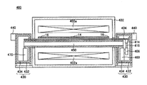
- FIG. 1 is a side cross-sectional view of a flat glass manufacturing apparatus including a heat treatment apparatus according to an embodiment of the present invention at a steady state.
- FIG. 2 is a side cross-sectional view of the plate glass manufacturing apparatus 100 at the time of startup.
- FIG. 3 is a sectional view taken along line III-III in FIG.
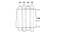
- FIG. 4 is a top view showing the internal structure of the heat treatment furnace 402 of FIG.
- FIG. 5 is a side view showing the internal structure of the heat treatment furnace 402 of FIG.
- FIGS. 6A and 6B are front views of a first modification and a second modification of the transport roll.
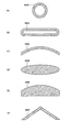
- FIGS. 7A to 7F are cross-sectional views of first to sixth modifications of the vibrator.
- FIGS. 8G to 8L are cross-sectional views of seventh to twelfth modifications of the vibrator.
- FIGS. 9M to 9P are cross-sectional views of thirteenth to sixteenth modifications of the vibrator.
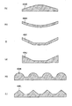
- FIGS. 10A and 10B are cross-sectional views of a first modification and a second modification of the reflector.
- FIG. 11C and FIG. 11D are front views of a third modification and a fourth modification of the reflector.
- FIG. 12 is a cross-sectional view showing a fifth modification (tilt mechanism) of the reflector.
- FIGS. 13F to 13J are cross-sectional views of sixth to tenth modifications of the reflector.
- a heat treatment apparatus for a plate glass manufacturing apparatus will be described.
- this heat treatment apparatus may be applied to a heat treatment apparatus that heat treats glass products (for example, window glass for automobiles),
- the present invention may be applied to a heat treatment apparatus for heat treating ceramics, resin, metal, or the like.
- the shape of the article to be heat-treated by the heat treatment apparatus 400 may not be a plate shape.
- FIG. 1 is a side sectional view of a flat glass manufacturing apparatus provided with a heat treatment apparatus according to an embodiment of the present invention at a steady state.
- FIG. 2 is a side cross-sectional view of the plate glass manufacturing apparatus 100 at the time of startup.
- FIG. 3 is a sectional view taken along line III-III in FIG.
- the plate glass manufacturing apparatus 100 heats and melts the glass raw material 10 to form a melting apparatus 200 for producing a molten glass 12 and a molten glass 12 produced by the melting apparatus 200.
- a molding apparatus 300 for producing the plate-shaped molded glass 14 and a heat treatment apparatus 400 for heat-treating the molded glass 14 produced by the molding apparatus 300 are provided.
- the melting device 200 is a device that melts the glass raw material 10 to produce the molten glass 12.
- the melting apparatus 200 may be a general one, and includes a raw material inlet 202 and a melting tank 204.
- the glass raw material 10 charged into the melting tank 204 from the raw material charging port 202 is heated by flame heat from the burner 206 and gradually melts into the molten glass 12 accommodated in the melting tank 204.
- the glass raw material 10 is prepared by mixing a plurality of types of materials according to the use of the product. For example, when manufacturing the glass substrate for liquid crystal displays (LCD), the glass raw material 10 is prepared so that it may become an alkali free glass substantially not containing an alkali metal oxide. Moreover, when manufacturing the glass substrate for plasma displays (PDP) and the window glass for motor vehicles, the glass raw material 10 is prepared so that it may become soda-lime glass.
- LCD liquid crystal displays
- PDP plasma displays
- the glass raw material 10 is prepared so that it may become soda-lime glass.
- the forming apparatus 300 is an apparatus that forms the molten glass 12 produced by the melting apparatus 200 to produce the band-shaped shaped glass 14.
- the molding apparatus 300 may be a general apparatus, for example, a float molding apparatus as shown in FIG.
- the float forming apparatus is an apparatus that continuously supplies the molten glass 12 to the bath surface of the molten tin 304 in the bathtub 302 and forms it into a strip shape.
- the molding apparatus 300 is not limited to a float molding apparatus, and may be a fusion molding apparatus, for example.
- the fusion molding apparatus is an apparatus that continuously supplies the molten glass 12 into the inside of the ridge, and joins the molten glass 12 overflowing from the ridge to the left and right sides at the lower edge of the ridge to form a strip.
- the heat treatment apparatus 400 is an apparatus that heat-treats the molded glass 14 molded by the molding apparatus 300.
- the heat treatment apparatus 400 includes a heat treatment furnace 402 that heat-treats the shaped glass (corresponding to the article of the present invention) 14, a vibrator 404 that is at least partially disposed inside the heat treatment furnace 402, and a vibrator that excites the vibrator 404. 406 (see FIG. 3).
- a plurality of electric heaters 402a are installed in order to precisely control the ambient temperature and the temperature of the formed glass 14.
- the position and size of the heater 402a are determined according to the thermal balance in the heat treatment furnace 402.
- the heater 402a is suspended from the ceiling in the furnace, installed on the hearth, or installed on the side wall in the furnace.
- the heater 402 a extends in the width direction of the heat treatment furnace 402 (direction parallel to the width direction of the formed glass 14). Note that a plurality of heaters 402 a may be arranged in the width direction of the heat treatment furnace 402.
- This heat treatment apparatus 400 floats the molded glass 14 above the vibrating body 404 by the radiation pressure of the sound wave from the vibrating body 404 inside the heat treatment furnace 402. Thereby, the molded glass 14 can be supported in a non-contact manner, and damage to the molded glass 14 can be suppressed.
- the heat treatment furnace 402 is a furnace for heat-treating the molded glass 14 at a temperature higher than room temperature.
- an electric furnace or a gas furnace is used as the heat treatment furnace 402.
- the heat treatment furnace 402 may be set so that its internal temperature becomes lower or lower as it goes from the inlet 408 to the outlet 410.
- An example of the heat treatment furnace that gradually decreases in temperature is a slow cooling furnace.
- the formed glass 14 is conveyed from the inlet 408 of the heat treatment furnace 402 to the outlet 410, and after being gradually cooled, is cut into a desired dimensional shape to become a product plate glass.
- molding glass 14 are the parts cut off by a cutting process normally, and are parts which do not become a product.
- thermoelectric furnace 402 may be appropriately set according to the application of the heat treatment apparatus 400.
- the vibrating body 404 As shown in FIG. 3, at least a part of the vibrating body 404 is disposed inside the heat treatment furnace 402.
- the vibrating body 404 is formed, for example, in a strip shape and is disposed substantially horizontally.
- the shape and arrangement of the vibrating body 404 are not particularly limited, and may be set as appropriate according to the shape and arrangement of the molded glass 14.
- One end in the longitudinal direction of the vibrating body 404 is connected to the vibrator 406 via a vibration transmitting member such as a horn 414 or a booster 416.
- the vibration of the vibrator 406 is transmitted to one end in the longitudinal direction of the vibrating body 404 by the vibration transmitting member.
- the vibration transmitting member may be omitted, and in this case, the vibrating body 404 and the vibrator 406 are directly connected.
- the other longitudinal end of the vibrating body 404 is a free end.
- the other end portion in the longitudinal direction of the vibrating body 404 may be a fixed end portion, or may be connected to the vibrator 406 via a vibration transmitting member, similarly to the one end portion in the longitudinal direction of the vibrating body 404. .
- a part of the vibrating body 404 is outside the heat treatment furnace 402.
- the vibrating body 404 penetrates the heat treatment furnace 402 in the width direction, and both longitudinal ends of the vibration body 404 are exposed to the outside of the heat treatment furnace 402.
- the vibrator 406 outside the heat treatment furnace 402 by taking a part of the vibrating body 404 out of the heat treatment furnace 402. Further, the first elevating device 460 that supports the vibrator 406 so as to be movable up and down can be provided outside the heat treatment furnace 402.
- a plurality of vibrating bodies 404 are installed at intervals along the conveying direction of the formed glass 14 over the entire area of the heat treatment furnace 402.
- the vibrating body 404 is installed at least in a high temperature region in the heat treatment furnace 402 (for example, near the inlet 408 of the heat treatment furnace 402). This is because, in the high temperature region, the molded glass 14 is softened, so that it is easily damaged.
- the vibrating body 404 is formed of a material corresponding to the internal temperature of the heat treatment furnace 402 and the like.
- a material of the vibrating body 404 for example, stainless steel, carbon, aluminum, an aluminum alloy, titanium, a titanium alloy, nickel, a nickel alloy, or the like is used. Since stainless steel and carbon have a relatively high melting point, they have excellent heat resistance, and aluminum and aluminum alloys have excellent toughness.
- carbon is used as the material of the vibrating body 404, it is preferable to make the inside of the heat treatment furnace 402 an inert atmosphere such as a nitrogen atmosphere in order to prevent oxidation of the vibrating body 404.
- ceramics, manganese steel, cast iron, or the like can be used as a material of the vibrating body 404.
- the vibrating body 404 may be a substrate whose surface is coated to improve corrosion resistance and oxidation resistance.
- a thermal spraying method for example, a thermal spraying method, a plating method, a vapor deposition method (including a PVD method and a CVD method) or the like is used.
- the coding layer formed by the thermal spraying method is made of, for example, a super hard material such as tungsten carbide, ceramics, or a heat resistant alloy such as a Ni-based alloy or a Cr-based alloy.
- the coding layer formed by the plating method is made of, for example, a Cr-based alloy or a Ni-based alloy.
- the coding layer formed by the vapor deposition method is made of, for example, diamond-like carbon (DLC).
- DLC diamond-like carbon
- both ends in the longitudinal direction of the vibrating body 404 are taken out of the heat treatment furnace 402, but only one end in the longitudinal direction of the vibrating body 404 may be put out of the heat treatment furnace 402. Also in this case, the vibrator 406 and the like can be provided outside the heat treatment furnace 402.
- the longitudinal direction of the vibrating body 404 is parallel to the width direction of the heat treatment furnace 402, but may be vertical or oblique.
- the vibrator 406 is fixed directly or indirectly (for example, via a lifting device) to the furnace wall or hearth of the heat treatment furnace 402.
- the vibrator 406 excites the vibrating body 404 and is provided for each vibrating body 404.
- the plurality of vibrators 406 may vibrate with the same phase or with different phases.
- the vibrator 406 may be an ultrasonic vibrator, and is composed of, for example, a piezoelectric element or a magnetostrictive element.
- the vibrator 406 vibrates longitudinally under the control of a control device such as a computer. When this longitudinal vibration is transmitted to the vibrating body 404, the vibrating body 404 bends and vibrates in the vertical direction, and a sound wave is generated from the vibrating body 404 in the vertical direction.
- the waveform formed by the flexural vibration of the vibrating body 404 is preferably a standing wave.
- the molded glass 14 may be conveyed in an unintended direction by the radiation pressure of the sound wave from the vibrating body 404.
- the molded glass 14 can be transported in a desired direction using the radiation pressure of sound waves from the vibrating body 404.
- the frequency of flexural vibration of the vibrating body 404 is appropriately set according to the shape and dimensions of the vibrating body 404, for example, but is preferably 15 to 50 kHz. If it falls below 15 kHz, it becomes a human audible range, which is an obstacle to work. Moreover, it is difficult to generate vibration exceeding 50 kHz due to the nature of the power source and the vibrator 406.
- the frequency is more preferably 18 to 30 kHz, and further preferably about 19.5 kHz.
- the amplitude of the flexural vibration of the vibrating body 404 is preferably 0.25 to 50 ⁇ m.
- “amplitude” means the maximum displacement from the center of vibration.
- the molded glass 14 can be sufficiently floated, and when it is 50 ⁇ m or less, the occurrence of breakage of the vibrating body 404 or the like can be suppressed.
- the vibrator 406 is installed outside the heat treatment furnace 402 as shown in FIG. Thereby, thermal deterioration of the vibrator 406 can be reduced.
- the vibrator 406 may be disposed in a heat insulating box 430 provided outside the heat treatment furnace 402. It is desirable to cool.
- the heat treatment apparatus 400 includes a heat insulating box 430, a cooling apparatus 440, a reflector 450, first and second elevating apparatuses 460 and 470, a conveyance roll 480 (see FIG. 1) as a conveyance member, And a support roll 490 (see FIG. 1).
- a heat insulating box 430 As shown in FIG. 3 and the like, the heat treatment apparatus 400 includes a heat insulating box 430, a cooling apparatus 440, a reflector 450, first and second elevating apparatuses 460 and 470, a conveyance roll 480 (see FIG. 1) as a conveyance member, And a support roll 490 (see FIG. 1).
- a conveyance roll 480 see FIG. 1
- a support roll 490 see FIG. 1
- the heat insulation box 430 is installed outside the heat treatment furnace 402 as shown in FIG.
- the heat insulating box 430 is provided at least on the vibrator 406 side, but may be provided on both sides. Inside the heat insulation box 430 (on the vibrator 406 side), the vibrator 406, the first lifting device 460, and the like are arranged. When the heat insulation boxes 430 are provided on both sides, the second lifting device 470 and the like are disposed in the other heat insulation box 430. As a result, thermal deterioration of the vibrator 406, the first and second lifting devices 460, 470, and the like can be suppressed.
- the heat insulation box 430 includes, for example, a housing 432 and a heat insulating material 434 attached to the inner wall surface of the housing 432.
- the housing 432 is made of, for example, heat resistant steel such as SS material, and functions as a sound insulating member that blocks noise generated by the vibrator 406 and the like.
- the heat insulating material 434 is made of, for example, glass wool or gypsum board, and also functions as a sound absorbing material that absorbs noise generated by the vibrator 406 and the like.
- the heat insulation box 430 may be fixed so as to be in contact with the heat treatment furnace 402. However, in order to limit heat transfer from the heat treatment furnace 402, for example, as shown in FIG. You may do it.
- the cooling device 440 is a device that cools the inside of the heat insulating box 430.
- the cooling device 440 is provided for each heat insulation box 430 and is fixed to the heat insulation box 430.
- the cooling device 440 cools the inside of the heat insulation box 430 by blowing cooling gas into the heat insulation box 430 or cooling the outer wall of the heat insulation box 430, for example. Thereby, it is possible to further suppress the thermal deterioration of the vibrator 406, the first and second elevating devices 460, 470, etc. arranged in the heat insulating box 430.
- the reflector 450 is provided below the vibrating body 404 and reflects sound waves from the vibrating body 404 toward the vibrating body 404.
- the vibrating body 404 can be floated above the reflector 450 by the radiation pressure of the reflected wave, and deformation of the vibrating body 404 by its own weight can be suppressed. This effect is remarkable when the other longitudinal end of the vibrating body 404 is a free end.
- the reflector 450 may be provided for each vibrating body 404, or may be configured such that a plurality of vibrating bodies 404 share one reflector.
- the reflector 450 is fixed directly or indirectly to the furnace wall or hearth of the heat treatment furnace 402 (for example, via a lifting device).
- the reflector 450 is installed in parallel with the vibrating body 404, and the upper surface thereof is a horizontal plane.
- the shape and arrangement of the reflector 450 are not particularly limited, and may be set as appropriate according to the shape and arrangement of the vibrating body 404.
- the reflector 450 is formed in a square ring shape as shown in FIG. 1, for example, in order to increase the moment of inertia of the cross section.
- the cross-sectional shape is an inverted U shape, an I shape, a T shape, an inverted L shape, a Z shape, or the like. There may be.
- a part of the reflector 450 comes out of the heat treatment furnace 402.
- the reflector 450 passes through the heat treatment furnace 402 in the width direction, and both longitudinal ends of the reflector 450 are exposed to the outside of the heat treatment furnace 402.
- At least one of the first and second elevating devices 460 and 470 that support the reflector 450 so as to be able to move up and down is attached to the heat treatment furnace 402. It can be provided outside.
- the width W1 (see FIG. 5) of the reflector 450 is preferably 50% or more of the width W2 of the vibrator 404 when the reflector 450 is provided for each vibrator 404. By setting it to 50% or more, the radiation pressure of the sound wave from the reflector 450 can be sufficiently increased, and the vibrating body 404 can be sufficiently supported without contact. A more preferable range is 80% or more.
- the width W1 of the reflector 450 exceeds 150% of the width W2 of the vibrator 404, the radiation pressure of the sound wave from the reflector 450 becomes saturated, and the installation space for the reflector 450 becomes excessive. . Therefore, the width W1 of the reflector 450 is preferably 150% or less of the width W2 of the vibrating body 404.
- the Young's modulus of the reflector 450 is preferably 70 GPa or more. By setting it as 70 GPa or more, the weight change of the reflector 450 can fully be suppressed.
- a more preferable range is 190 GPa or more, and a further preferable range is 210 GPa or more.
- the melting point of the reflector 450 is preferably 1300 ° C. or higher. By setting it as 1300 degreeC or more, softening of the reflector 450 can fully be suppressed. A more preferable range is 1500 ° C. or higher, and a further preferable range is 1700 ° C. or higher.
- the material of the reflector 450 is not particularly limited, but may be a heat-resistant steel such as stainless steel or a ceramic material such as silica.
- a heat-resistant steel such as stainless steel or a ceramic material such as silica.
- SUS310S is used as the stainless steel.
- the first lifting device 460 is a device that supports the vibrator 406 (and thus the vibrating body 404) so as to be lifted and lowered with respect to the hearth of the heat treatment furnace 402.
- the first lifting device 460 may have a general configuration, and is configured with a hydraulic jack or the like. Thereby, the positional relationship between the vibrating body 404 and the molded glass 14 can be optimized.
- the first lifting device 460 is provided for each vibrating body 404.
- the first lifting device 460 is provided outside the heat treatment furnace 402. Thereby, the thermal degradation of the first lifting device 460 can be suppressed.
- the first lifting device 460 may be disposed in the heat insulation box 430. In that case, the inside of the heat insulation box 430 is cooled by the cooling device 440. Is desirable.
- the first elevating device 460 has a function of supporting the one end in the longitudinal direction of the reflector 450 so as to be movable up and down in addition to the function of supporting the vibrating body 404 so as to be movable up and down with respect to the hearth of the heat treatment furnace 402. ing. It is desirable that the vibrating body 404 and the reflector 450 can be moved up and down independently. Thereby, the positional relationship between the reflector 450 and the vibrating body 404 can be optimized.
- the second lifting device 470 is a device that supports the other end portion of the reflector 450 in the longitudinal direction with respect to the hearth of the heat treatment furnace 402 so as to be lifted and lowered. Similar to the first lifting device 460, the second lifting device 470 may have a general configuration. The second lifting device 470 is provided for each reflector 450.
- the second lifting device 470 is provided outside the heat treatment furnace 402 as shown in FIG. Thereby, the thermal deterioration of the second lifting device 470 can be suppressed. Similar to the first lifting device 460, the second lifting device 470 may be disposed in the heat insulation box 430. In that case, it is desirable to cool the heat insulation box 430 by the cooling device 440.
- one or more lifting devices are provided so as to support the center in the longitudinal direction of the reflector 450 or the vicinity thereof. Also good. When the reflector 450 is long, its center may bend due to its own weight and the floating of the vibrating body 404 may become unstable, but the third lifting device supports the center of the reflector 450 in the longitudinal direction or the vicinity thereof. Therefore, the deflection of the vibrating body 404 can be stabilized.
- the transport roll 480 transports the molded glass 14 in the heat treatment furnace 402 in a predetermined direction. This makes it possible to change the temperature of the formed glass 14 with the lapse of time using the temperature distribution in the heat treatment furnace 402.
- a plurality of transport rolls 480 are provided at intervals along the transport direction of the shaped glass 14.
- the plurality of transport rolls 480 are driven to rotate around the respective central axes, and transport the molded glass 14 in contact with the outer peripheral surface thereof.
- the peripheral speed of each transport roll 480 is substantially the same as the transport speed of the molded glass 14.
- Each conveyance roll 480 is, for example, a columnar shape and may have a hollow structure.
- the transport roll 480 is preferably installed in a low temperature region in order to suppress damage to the molded glass 14.
- the transport roll 480 may be installed near the outlet 410 outside the heat treatment furnace 402 as shown in FIG. 1, or may be installed near the outlet 410 or near the center in the heat treatment furnace 402.
- the transport roll 480 may be installed near the inlet 408 in the heat treatment furnace 402. Also in this case, the contact pressure between the transport roll 480 and the molded glass 14 is reduced by the radiation pressure of the sound wave from the vibrating body 404, so that damage to the molded glass 14 can be suppressed.
- FIGS. 6A and 6B are front views of a first modification and a second modification of the transport roll.
- the transport rolls 480A and 480B shown in FIGS. 6A and 6B can be used instead of the transport roll 480 shown in FIG.
- a transport roll 480A shown in FIG. 6 (A) includes rotatable rotating portions 482A and 482A that are in contact with both end portions 16 in the width direction of the formed glass 14, and a rotating shaft portion 484A that coaxially connects the rotating portions 482A and 482A. It consists of.
- the outer diameter of the rotating shaft portion 484A is smaller than the outer diameter of the rotating portion 482A, and the transport roll 480A contacts only the width direction both ends 16 of the molded glass 14.
- Both end portions 16 in the width direction of the formed glass 14 are portions that are cut off during the manufacturing process of the plate glass, and are portions that do not become products. Therefore, damage to the formed glass 14 by the transport roll 480A does not become a problem.
- a transport roll 480B shown in FIG. 6 (B) has rotatable rotating parts 482B and 482B that are in contact with both ends 16 in the width direction of the formed glass 14, and a rotating shaft part 484B that coaxially connects the rotating parts 482B and 482B. And an annular projecting portion 486B projecting radially outward from the rotating shaft portion 484B.
- the outer peripheral surface of the protruding portion 486B contacts the planned cutting portion of the molded glass 14.
- the planned cutting part is a part scheduled to cut the molded glass 14 into a plurality of plate glasses. The part to be cut becomes the outer edge part of the plate glass after cutting.
- the outer edge portion of the glass substrate is a portion where a thin film transistor (TFT), a color filter (CF), or the like is not formed.
- the support roll 490 is provided inside the heat treatment furnace 402 and can support the molded glass 14.
- a plurality of support rolls 490 are provided at intervals along the conveying direction of the molded glass 14.
- the plurality of support rolls 490 are rotationally driven around their respective central axes, and convey the molded glass 14 in contact with the outer peripheral surface thereof.
- the peripheral speed of each support roll 490 is substantially the same as the conveyance speed of the molded glass 14.
- Each support roll 490 has, for example, a cylindrical shape, but may have the same shape as the transport rolls 480A and 480B shown in FIGS. 6 (A) and 6 (B).
- Each support roll 490 may have a hollow structure.
- one vibrating body 404 is disposed one by one. That is, the support roll 490 and the vibrating body 404 are alternately and repeatedly arranged at intervals along the conveying direction of the molded glass 14.
- the conveyance by the vibrating body 404 hardly damages the molded glass 14, and the conveyance by the support roll 490 can stably convey the molded glass 14.
- the arrangement order of the support roll 490 and the vibrating body 404 is not particularly limited, and may be appropriately set according to the application.
- the support roll 490 can be moved up and down relatively with respect to the vibrating body 404. That is, at least one of the support roll 490 and the vibrating body 404 can be moved up and down with respect to the hearth of the heat treatment furnace 402. Thereby, as shown in FIG. 1, the support roll 490 can be separated from the molded glass 14 as necessary.
- the support roll 490 of this embodiment is installed over the whole region of the heat treatment furnace 402, the installation position is not limited.
- the support roll 490 may be installed only in a high temperature region in the heat treatment furnace 402 (for example, in the vicinity of the inlet 408 in the heat treatment furnace 402).
- the molded glass 14 tends to be thick or the thickness and shape thereof are not uniform, so that the molded glass 14 is disposed above the vibrating body 404 by the radiation pressure of sound waves from the vibrating body 404. May be difficult to surface.
- the support roll 490 is brought into contact with the molded glass 14 to support the molded glass 14, and the support roll 490 is rotationally driven to convey the molded glass 14 in a predetermined direction.
- the support roll 490 is separated from the molded glass 14 as shown in FIG. Thereby, damage to the molded glass 14 by the support roll 490 can be prevented. Note that the rotation of the support roll 490 may be stopped after the support roll 490 is separated from the molded glass 14. Note that the support roll 490 can be omitted by arranging the plurality of vibrating bodies 404 densely.
- FIG. 9P shows the first to sixteenth modifications of the vibrator.
- FIG. The cross section is a cross section perpendicular to the longitudinal direction (extending direction) of the vibrating body.
- the longitudinal direction of the vibrating body is the horizontal direction.
- the horizontal direction in FIGS. 7A to 7F, 8G to 8L, and 9M to 9P is the longitudinal direction of the vibrating body and the vertical direction. It is a direction perpendicular to both directions.
- FIG. 9P shows a vibrating body 404P and a reflector 450P that reflects a sound wave from the vibrating body 404P toward the vibrating body 404P.
- the upper surfaces of the vibrating bodies 404A to 404L shown in FIGS. 7 (A) to 7 (F) and FIGS. 8 (G) to 8 (L) disperse the radiation pressure of the sound waves from the vibrating body toward the molded glass. In order to concentrate, it has several parts from which a normal line direction differs.
- the upper surfaces of the vibrating bodies 404A to 404G shown in FIGS. 7A to 7F and 8G are for diffusing the radiation pressure of sound waves from the vibrating body toward the molded glass in the left-right direction.
- the left and right end portions are configured to be positioned below the left and right center portion.
- the upper surface of the vibrating body is configured by a curved surface, a plurality of planes, or a combination of a curved surface and a plane.
- the upper surface of the vibrating body is an arc surface as shown in FIG. 7 (A), a horizontal plane as shown in FIG. 7 (B), and an arc surface extending downward from both left and right ends of the plane. 7C, a curved surface convex upward as shown in FIGS.
- the vibrating body may be solid or hollow, and the configuration of the lower surface of the vibrating body is not particularly limited.
- the upper surfaces of the vibrating bodies 404H to 404J shown in FIGS. 8 (H) to 8 (J) concentrate the radiation pressure of the sound wave directed from the vibrating body to the molded glass in the left and right direction, so that both ends in the left and right direction are It is comprised so that it may be located below rather than the center part in the left-right direction.
- the upper surface of the vibrating body is configured by a curved surface, a plurality of planes, or a combination of a curved surface and a plane.
- the upper surface of the vibrating body is a downwardly convex curved surface as shown in FIG. 8 (H), a horizontal plane as shown in FIGS. 8 (I) to 8 (J), and both left and right ends of the plane. It is comprised by the combination with the inclined surface extended diagonally upwards from a part.
- the vibrating body may be solid or hollow, and the configuration of the lower surface of the vibrating body is not particularly limited.
- the upper surfaces of the vibrating bodies 404K and 404L shown in FIGS. 8 (K) and 8 (L) concentrate or diffuse the radiation pressure of the sound waves from the vibrating body toward the molded glass in the left-right direction. It has unevenness along the left-right direction.
- the upper surface of the vibrating body is configured by a curved surface, a plurality of planes, or a combination of a curved surface and a plane.
- the vibrating body may be solid or hollow, and the configuration of the lower surface of the vibrating body is not particularly limited.
- the vibrating bodies 404M and 404N shown in FIGS. 9M and 9N have a quadrangular cross-sectional shape as shown in FIG. 9M, and are shown in FIG. 9N. Thus, it is formed in an inverted U shape. Note that the vibrating bodies 404A to 404E shown in FIGS. 7A to 7E also have relatively high rigidity.
- the vibrating body 404O shown in FIG. 9O has a cross-sectional shape formed in a comb shape. A portion having a long vertical dimension is difficult to vibrate in the vertical direction, and a portion having a short vertical dimension is likely to vibrate in the vertical direction. Therefore, the vibrating body 404O can be vibrated by being divided into a plurality of regions in the width direction, and vibration unevenness in the width direction of the vibrating body 404O can be suppressed. The same effect can be obtained when the cross-sectional shape is T-shaped.
- the vibrating body 404P shown in FIG. 9 (P) is plate-shaped and has a plurality of through holes 404Pa penetrating in the plate thickness direction.
- a rectangular tube-shaped reflector 450P is disposed below the vibrating body 404P, and a plurality of ejection holes 450Pa for ejecting the gas supplied to the inner space of the reflector 450P to the outside are formed above the reflector 450P. Yes.
- the gas ejected from the ejection hole 450Pa is blown to the lower surface of the formed glass through the through-hole 404Pa formed in the vibrating body 404P.
- the rising of the shaped glass can be supported by the wind pressure of the gas.
- the temperature distribution can be adjusted by the gas carrying heat.
- FIGS. 10A and 10B are cross-sectional views of a first modification and a second modification of the reflector.
- the cross section is a cross section perpendicular to the longitudinal direction (extending direction) of the reflector.
- the longitudinal direction of the reflector is a horizontal direction and is substantially parallel to the longitudinal direction of the vibrating body.
- the left-right direction in FIGS. 10A and 10B is a direction perpendicular to both the longitudinal direction and the up-down direction of the reflector.
- the upper surface of the reflectors 450A and 450B is a curved surface along the lower surface of the vibrator.
- the upper surface of the reflector 450A shown in FIG. 10 (A) is a convex curved surface that goes upward as it goes from the left and right ends to the center in the left and right direction.
- This convex curved surface is applied to, for example, the vibrating bodies 404C, 404F, and 404N shown in FIGS. 7C, 7F, and 9N.
- the upper surface of the reflector 450B shown in FIG. 10B is a concave curved surface that goes downward as it goes from the left and right ends to the center in the left and right direction.
- This concave curved surface is applied to the vibrating bodies 404A, 404D, 404H and 404I shown in FIGS. 7A, 7D, 8H and 8I, for example.
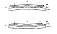
- FIG. 11C and FIG. 11D are front views of a third modification and a fourth modification of the reflector. 11C and 11D show the reflectors 450C and 450D, the vibrating body 404, and the molded glass 14. FIG. The left-right direction in FIGS. 11C and 11D is a direction parallel to the width direction of the formed glass 14.
- the upper surface of the reflector 450C shown in FIG. 11C is a convex curved surface that goes upward as it goes from the left and right ends to the center in the left and right direction.
- the upper surface of the vibrating body 404 becomes a convex curved surface that goes upward as it goes from the left and right ends to the center in the left and right direction. Therefore, since the radiation pressure of the sound wave from the vibrating body 404 acts so as to stretch the molded glass 14 outward in the width direction, the wrinkles of the molded glass 14 are removed. At this time, gravity also contributes to removing wrinkles of the molded glass 14.
- the upper surface of the reflector 450D shown in FIG. 11D is a concave curved surface that goes downward from the left and right end portions toward the left and right direction central portion.
- the upper surface of the vibrating body 404 becomes a concave curved surface that goes downward from the both ends in the left-right direction toward the center in the left-right direction. Therefore, since the radiation pressure of the sound wave from the vibrating body 404 acts so as to bring the molded glass 14 inward in the width direction, it is possible to limit the shift in the width direction when the molded glass 14 is conveyed in the longitudinal direction. it can.
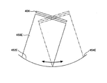
- FIG. 12 is a side view showing a reflector provided with a tilt mechanism.
- a solid line indicates a state when the reflector 450E is at the left end position of the rotation range
- a two-dot chain line indicates a state when the reflector 450E is at the right end position of the rotation range.
- the heat treatment apparatus 400 may have a tilt mechanism that rotates the reflector 450E around an axis parallel to the longitudinal direction (horizontal direction) of the reflector 450E.
- the tilt mechanism includes an arcuate support surface 454E that rotatably supports an arcuate lower surface 452E of the reflector 450E.
- the center of curvature of the support surface 454E becomes the rotation axis of the reflector 450E. This rotation axis is set so as to be located at the center of the thickness direction of the molded glass or in the vicinity thereof.
- the reflector 450E When the reflector 450E is rotated by a motor or the like, the direction of the radiation pressure of the reflected wave from the reflector 450E changes. As a result, since the posture of the vibrating body 404 changes, the direction of the radiation pressure of the sound wave from the vibrating body 404 can be adjusted. In order to reduce unevenness in the radiation pressure of the sound wave from the vibrating body 404, the reflector 450E may be rotated forward and backward repeatedly.
- the heat treatment apparatus 400 includes a slide mechanism that slides the reflector 450 in the width direction and / or the longitudinal direction of the heat treatment furnace 402, and another structure that rotates the reflector 450 about an axis parallel to the longitudinal direction of the heat treatment furnace 402. You may further have a tilt mechanism.
Landscapes
- Chemical & Material Sciences (AREA)
- Engineering & Computer Science (AREA)
- Materials Engineering (AREA)
- Organic Chemistry (AREA)
- Physics & Mathematics (AREA)
- Thermal Sciences (AREA)
- Re-Forming, After-Treatment, Cutting And Transporting Of Glass Products (AREA)
- Glass Compositions (AREA)
- Jigging Conveyors (AREA)
- Apparatuses For Generation Of Mechanical Vibrations (AREA)
Abstract
Description
物品を熱処理する熱処理炉と、該熱処理炉の内部に少なくとも一部が配置される振動体と、該振動体を励振させる振動子とを備え、
前記熱処理炉の内部において、前記振動体からの音波の放射圧によって前記振動体の上方に前記物品を浮かす熱処理装置である。
物品を熱処理する熱処理炉の内部において、振動体を励振させ、該振動体からの音波の放射圧によって前記振動体の上方に前記物品を浮かす熱処理方法である。
溶解装置200は、ガラス原料10を溶解して、溶融ガラス12を作製する装置である。溶解装置200は、一般的なものであって良く、原料投入口202および溶解槽204を備えている。原料投入口202から溶解槽204へ投入されたガラス原料10は、バーナー206からの火炎熱などによって加熱され、溶解槽204内に収容される溶融ガラス12に徐々に融け込む。
成形装置300は、溶解装置200で作製された溶融ガラス12を成形して、帯板状の成形ガラス14を作製する装置である。成形装置300は、一般的なものであって良く、例えば図1に示すように、フロート成形装置であって良い。フロート成形装置は、浴槽302内の溶融錫304の浴面に溶融ガラス12を連続的に供給して、帯板状に成形する装置である。
熱処理装置400は、成形装置300で成形された成形ガラス14を熱処理する装置である。熱処理装置400は、成形ガラス(本発明の物品に相当)14を熱処理する熱処理炉402と、熱処理炉402の内部に少なくとも一部が配置される振動体404と、振動体404を励振させる振動子406(図3参照)とを備える。
熱処理炉402は、成形ガラス14を室温よりも高温で熱処理する炉である。熱処理炉402としては、例えば電気炉、ガス炉などが用いられる。熱処理炉402はその内部温度が入口408から出口410に行くほど低温になるように設定しても高温になるように設定してもよい。徐々に低温になる熱処理炉としては徐冷炉が挙げられる。
振動体404は、図3に示すように、熱処理炉402の内部に少なくとも一部が配置される。振動体404は、例えば帯板状に形成され、略水平に配置される。なお、振動体404の形状や配置は、特に制限はなく、成形ガラス14の形状や配置などに応じて適宜設定して良い。
振動子406は、図3に示すように、熱処理炉402の炉壁又は炉床に対して直接的又は間接的に(例えば昇降装置を介して)固定されている。振動子406は、振動体404を励振させるものであって、振動体404毎に設けられる。複数の振動子406は、同じ位相で振動しても良いし、異なる位相で振動しても良い。
熱処理装置400は、図3などに示すように、断熱ボックス430、冷却装置440、反射体450、第1および第2の昇降装置460、470、搬送部材である搬送ロール480(図1参照)、ならびに支持ロール490(図1参照)をさらに備えている。以下、各構成について説明する。
断熱ボックス430は、図3に示すように、熱処理炉402の外部に設置されている。断熱ボックス430は、少なくとも振動子406側に設けるが、両側に設けてもよい。断熱ボックス430(振動子406側)の内部には、振動子406、第1の昇降装置460などが配置される。断熱ボックス430が両側に設けられている場合、他方の断熱ボックス430内には、第2の昇降装置470などが配置される。これによって、振動子406、第1および第2の昇降装置460、470などの熱劣化を抑制することができる。
冷却装置440は、図3に示すように、断熱ボックス430内を冷却する装置である。冷却装置440は、断熱ボックス430毎に設けられ、断熱ボックス430に固定されている。
反射体450は、図3に示すように、振動体404の下方に設けられ、振動体404からの音波を振動体404に向けて反射する。その反射波の放射圧によって、反射体450の上方に振動体404を浮かすことができ、振動体404の自重変形を抑えることができる。この効果は、振動体404の長手方向他端部が自由端部である場合に顕著である。
なお、反射体450の形状や配置は、特に制限はなく、振動体404の形状や配置などに応じて適宜設定して良い。
第1の昇降装置460は、図3に示すように、熱処理炉402の炉床に対して振動子406(ひいては、振動体404)を昇降可能に支持する装置である。第1の昇降装置460は、一般的な構成であって良く、油圧ジャッキなどで構成される。これによって、振動体404と成形ガラス14との位置関係を最適化することができる。第1の昇降装置460は、振動体404毎に設けられる。
第2の昇降装置470は、熱処理炉402の炉床に対して、反射体450の長手方向他端部を昇降可能に支持する装置である。第2の昇降装置470は、第1の昇降装置460と同様に、一般的な構成であって良い。第2の昇降装置470は、反射体450毎に設けられる。
搬送ロール480は、図1に示すように、熱処理炉402の内部にある成形ガラス14を所定方向に搬送する。これによって、熱処理炉402内の温度分布を利用して、成形ガラス14の温度を経時変化させることができる。
図6(A)および図6(B)は、搬送ロールの第1変形例および第2変形例の正面図である。図6(A)および図6(B)に示す搬送ロール480Aおよび480Bは、図1に示す搬送ロール480に代えて用いることができる。
支持ロール490は、例えば図2に示すように、熱処理炉402の内部に設けられ、成形ガラス14を支持可能なものである。支持ロール490は、成形ガラス14の搬送方向に沿って、間隔をおいて複数設けられている。複数の支持ロール490は、それぞれの中心軸の周りに回転駆動され、その外周面に接触する成形ガラス14を搬送する。各支持ロール490の周速度は、成形ガラス14の搬送速度と略同一になっている。各支持ロール490は、例えば円柱状であるが、図6(A)および図6(B)に示す搬送ロール480Aおよび480Bと同様の形状であってもよい。また、各支持ロール490は、中空構造を有して良い。
例えば、板ガラス製造装置100のスタートアップ時には、成形ガラス14が厚くなったり、厚さや形状が不均一になる傾向があるので、振動体404からの音波の放射圧によって振動体404の上方に成形ガラス14を浮上させることが困難な場合がある。このような場合、図2に示すように、支持ロール490を成形ガラス14に接触させて成形ガラス14を支持すると共に、支持ロール490を回転駆動して成形ガラス14を所定方向に搬送する。
なお、複数の振動体404を密に配置することで、支持ロール490を用いないことも可能である。
図7(A)~図7(F)、図8(G)~図8(L)、および図9(M)~図9(P)は、振動体の第1変形例~第16変形例の断面図である。断面は、振動体の長手方向(延びる方向)と垂直な断面である。振動体の長手方向は水平方向である。図7(A)~図7(F)、図8(G)~図8(L)、および図9(M)~図9(P)中の左右方向は、振動体の長手方向、および上下方向の両方向に対して垂直な方向である。図9(P)は、振動体404Pと、振動体404Pからの音波を振動体404Pに向けて反射する反射体450Pとを示す。
図10(A)および図10(B)は反射体の第1変形例および第2変形例の断面図である。断面は、反射体の長手方向(延びる方向)と垂直な断面である。反射体の長手方向は、水平方向であって、振動体の長手方向と略平行である。図10(A)および図10(B)中の左右方向は、反射体の長手方向、および上下方向の両方向に対して垂直な方向である。
図12は、チルト機構を備えた反射体示す側面である。図12において、実線は反射体450Eが回動範囲の左端位置にあるときの状態を示し、2点鎖線は反射体450Eが回動範囲の右端位置にあるときの状態を示す。
本出願は、2010年11月8日出願の日本特許出願2010-250170に基づくものであり、その内容はここに参照として取り込まれる。
12 溶融ガラス
14 成形ガラス(物品)
100 板ガラス製造装置
200 溶解装置
300 成形装置
400 熱処理装置
402 熱処理炉
404 振動体
406 振動子
430 断熱ボックス
440 冷却装置
450 反射体
460 第1の昇降装置
470 第2の昇降装置
480 搬送ロール(搬送部材)
490 支持ロール
Claims (17)
- 物品を熱処理する熱処理炉と、該熱処理炉の内部に少なくとも一部が配置される振動体と、該振動体を励振させる振動子とを備え、
前記熱処理炉の内部において、前記振動体からの音波の放射圧によって前記振動体の上方に前記物品を浮かす熱処理装置。 - 前記振動体の一部が前記熱処理炉の外部に出ており、
前記振動子は前記熱処理炉の外部に設けられる請求項1に記載の熱処理装置。 - 前記振動体の上側の面は、法線方向が異なる複数の部分を有する請求項1又は2に記載の熱処理装置。
- 前記振動体の下方には、前記振動体からの音波を前記振動体に向けて反射する反射体が設けられる請求項1~3のいずれか一項に記載の熱処理装置。
- 前記反射体の幅は前記振動体の幅の50%以上である請求項4に記載の熱処理装置。
- 前記反射体のヤング率が70GPa以上である請求項4または5に記載の熱処理装置。
- 前記反射体の融点が1300℃以上である請求項4~6のいずれか1項に記載の熱処理装置。
- 前記振動体は、ステンレス鋼またはカーボンで形成される請求項1~7のいずれか1項に記載の熱処理装置。
- 前記振動体は、アルミニウムまたはアルミニウム合金で形成される請求項1~7のいずれか1項に記載の熱処理装置。
- 前記振動子によって励振された前記振動体の撓み振動の周波数が15~50kHzである請求項1~9のいずれか1項に記載の熱処理装置。
- 前記振動子によって励振された前記振動体の撓み振動の振幅が0.25~50μmである請求項1~10のいずれか1項に記載の熱処理装置。
- 前記熱処理炉の外部に設けられる断熱ボックスをさらに備え、
前記振動子は、前記断熱ボックス内に配置される請求項1~11のいずれか1項に記載の熱処理装置。 - 前記断熱ボックス内を冷却する冷却装置をさらに備える請求項12に記載の熱処理装置。
- 前記熱処理炉の内部にある前記物品を所定方向に搬送する搬送部材をさらに備える請求項1~13のいずれか1項に記載の熱処理装置。
- 前記熱処理炉の内部に設けられ、前記物品を支持可能な支持ロールをさらに備え、
前記支持ロールは、前記振動体に対して相対的に昇降可能である請求項14に記載の熱処理装置。 - 前記振動体と前記支持ロールは、前記物品の搬送方向に沿って、間隔をおいて交互に配置されている請求項15に記載の熱処理装置。
- 物品を熱処理する熱処理炉の内部において、振動体を励振させ、該振動体からの音波の放射圧によって前記振動体の上方に前記物品を浮かす熱処理方法。
Priority Applications (3)
| Application Number | Priority Date | Filing Date | Title |
|---|---|---|---|
| CN201180031740.6A CN102958856B (zh) | 2010-11-08 | 2011-09-13 | 热处理装置以及热处理方法 |
| JP2012524433A JP5874634B2 (ja) | 2010-11-08 | 2011-09-13 | 熱処理装置および熱処理方法 |
| KR1020127021274A KR101229184B1 (ko) | 2010-11-08 | 2011-09-13 | 열처리 장치 및 열처리 방법 |
Applications Claiming Priority (2)
| Application Number | Priority Date | Filing Date | Title |
|---|---|---|---|
| JP2010-250170 | 2010-11-08 | ||
| JP2010250170 | 2010-11-08 |
Publications (1)
| Publication Number | Publication Date |
|---|---|
| WO2012063550A1 true WO2012063550A1 (ja) | 2012-05-18 |
Family
ID=46050706
Family Applications (1)
| Application Number | Title | Priority Date | Filing Date |
|---|---|---|---|
| PCT/JP2011/070858 Ceased WO2012063550A1 (ja) | 2010-11-08 | 2011-09-13 | 熱処理装置および熱処理方法 |
Country Status (5)
| Country | Link |
|---|---|
| JP (1) | JP5874634B2 (ja) |
| KR (1) | KR101229184B1 (ja) |
| CN (1) | CN102958856B (ja) |
| TW (1) | TWI568694B (ja) |
| WO (1) | WO2012063550A1 (ja) |
Cited By (1)
| Publication number | Priority date | Publication date | Assignee | Title |
|---|---|---|---|---|
| JP2015032656A (ja) * | 2013-08-01 | 2015-02-16 | 東レエンジニアリング株式会社 | 基板浮上装置 |
Families Citing this family (1)
| Publication number | Priority date | Publication date | Assignee | Title |
|---|---|---|---|---|
| KR101876463B1 (ko) * | 2017-06-14 | 2018-07-16 | 한국생산기술연구원 | 초음파 부상모듈 및 초음파를 이용한 대상물 부상장치 |
Citations (4)
| Publication number | Priority date | Publication date | Assignee | Title |
|---|---|---|---|---|
| JPH09169427A (ja) * | 1995-12-22 | 1997-06-30 | Kaijo Corp | 浮揚装置及び該装置を具備した基板搬送装置 |
| JP2003290811A (ja) * | 2002-03-29 | 2003-10-14 | Jfe Steel Kk | 金属帯のパスライン安定方法及びその装置 |
| JP2005231812A (ja) * | 2004-02-19 | 2005-09-02 | Toyota Industries Corp | 音波浮揚装置 |
| JP2006029644A (ja) * | 2004-07-14 | 2006-02-02 | Koyo Thermo System Kk | 連続熱処理炉 |
Family Cites Families (5)
| Publication number | Priority date | Publication date | Assignee | Title |
|---|---|---|---|---|
| JPS5943724A (ja) * | 1982-09-02 | 1984-03-10 | Tokyo Erekutoron Kk | 超音波浮上型搬送装置 |
| JP3967855B2 (ja) * | 1999-09-28 | 2007-08-29 | 株式会社豊田自動織機 | 物体浮揚装置 |
| JP4048313B2 (ja) * | 2001-07-27 | 2008-02-20 | 株式会社豊田自動織機 | 物体浮揚装置 |
| JP3938554B2 (ja) * | 2003-03-26 | 2007-06-27 | 光洋サーモシステム株式会社 | 熱処理炉 |
| JP4001136B2 (ja) * | 2003-11-13 | 2007-10-31 | 株式会社豊田自動織機 | 音波浮揚装置 |
-
2011
- 2011-09-13 CN CN201180031740.6A patent/CN102958856B/zh not_active Expired - Fee Related
- 2011-09-13 WO PCT/JP2011/070858 patent/WO2012063550A1/ja not_active Ceased
- 2011-09-13 JP JP2012524433A patent/JP5874634B2/ja not_active Expired - Fee Related
- 2011-09-13 KR KR1020127021274A patent/KR101229184B1/ko not_active Expired - Fee Related
- 2011-09-22 TW TW100134200A patent/TWI568694B/zh not_active IP Right Cessation
Patent Citations (4)
| Publication number | Priority date | Publication date | Assignee | Title |
|---|---|---|---|---|
| JPH09169427A (ja) * | 1995-12-22 | 1997-06-30 | Kaijo Corp | 浮揚装置及び該装置を具備した基板搬送装置 |
| JP2003290811A (ja) * | 2002-03-29 | 2003-10-14 | Jfe Steel Kk | 金属帯のパスライン安定方法及びその装置 |
| JP2005231812A (ja) * | 2004-02-19 | 2005-09-02 | Toyota Industries Corp | 音波浮揚装置 |
| JP2006029644A (ja) * | 2004-07-14 | 2006-02-02 | Koyo Thermo System Kk | 連続熱処理炉 |
Cited By (1)
| Publication number | Priority date | Publication date | Assignee | Title |
|---|---|---|---|---|
| JP2015032656A (ja) * | 2013-08-01 | 2015-02-16 | 東レエンジニアリング株式会社 | 基板浮上装置 |
Also Published As
| Publication number | Publication date |
|---|---|
| TW201219328A (en) | 2012-05-16 |
| KR101229184B1 (ko) | 2013-02-01 |
| JPWO2012063550A1 (ja) | 2014-05-12 |
| TWI568694B (zh) | 2017-02-01 |
| JP5874634B2 (ja) | 2016-03-02 |
| CN102958856B (zh) | 2016-04-06 |
| CN102958856A (zh) | 2013-03-06 |
| KR20120097420A (ko) | 2012-09-03 |
Similar Documents
| Publication | Publication Date | Title |
|---|---|---|
| CN102378742B (zh) | 玻璃陶瓷物品、以及用于使玻璃陶瓷化的方法和设备 | |
| CN104271520B (zh) | 声波浮起装置、声波浮起方法、板玻璃制造装置、及板玻璃制造方法 | |
| JP6379392B2 (ja) | ガラス基板の切断方法及びガラス基板の製造方法 | |
| CN103832826B (zh) | 浮起搬送热处理装置 | |
| CN103302009B (zh) | 热处理装置 | |
| JP5874634B2 (ja) | 熱処理装置および熱処理方法 | |
| JP2003048733A (ja) | ガラス板用ホルダー | |
| JP2000327355A (ja) | ガラス板支持リング | |
| WO2012118083A1 (ja) | 板状ガラス部材の割断方法、および割断装置 | |
| JP2006008350A (ja) | 物体浮上ユニットおよび物体浮上装置 | |
| JP4400158B2 (ja) | 板状体の加熱方法 | |
| WO2011122679A1 (ja) | ガラス板の成形強化装置およびガラス板の製造方法 | |
| JP2008512333A (ja) | ガラスシートの加熱方法およびその装置 | |
| JP2005239391A (ja) | 物体浮揚装置及び物体浮揚搬送装置 | |
| JP6454188B2 (ja) | ガラス基板の製造方法 | |
| JPH09113144A (ja) | 加熱炉 | |
| JP6053468B2 (ja) | 浮上搬送熱処理装置 | |
| JP3938554B2 (ja) | 熱処理炉 | |
| JP2931726B2 (ja) | 板ガラス成形体及びその製造法 | |
| TW201936539A (zh) | 具有減少的靜電電荷的玻璃片及其生產方法 | |
| JP4198830B2 (ja) | 成膜装置 | |
| JPH10306304A (ja) | 移動型炉床炉の操業方法 | |
| KR20160002392A (ko) | 유리 기판의 제조 방법 및 유리 기판 | |
| WO2019138787A1 (ja) | ガラス基板の製造方法 | |
| JP2012121715A (ja) | 搬送機構、及び、これを用いた真空処理装置 |
Legal Events
| Date | Code | Title | Description |
|---|---|---|---|
| WWE | Wipo information: entry into national phase |
Ref document number: 201180031740.6 Country of ref document: CN |
|
| WWE | Wipo information: entry into national phase |
Ref document number: 2012524433 Country of ref document: JP |
|
| 121 | Ep: the epo has been informed by wipo that ep was designated in this application |
Ref document number: 11839028 Country of ref document: EP Kind code of ref document: A1 |
|
| ENP | Entry into the national phase |
Ref document number: 20127021274 Country of ref document: KR Kind code of ref document: A |
|
| NENP | Non-entry into the national phase |
Ref country code: DE |
|
| 122 | Ep: pct application non-entry in european phase |
Ref document number: 11839028 Country of ref document: EP Kind code of ref document: A1 |