WO2012063393A1 - Automobile floor structure - Google Patents
Automobile floor structure Download PDFInfo
- Publication number
- WO2012063393A1 WO2012063393A1 PCT/JP2011/005214 JP2011005214W WO2012063393A1 WO 2012063393 A1 WO2012063393 A1 WO 2012063393A1 JP 2011005214 W JP2011005214 W JP 2011005214W WO 2012063393 A1 WO2012063393 A1 WO 2012063393A1
- Authority
- WO
- WIPO (PCT)
- Prior art keywords
- floor
- cross member
- vehicle body
- cross
- frame
- Prior art date
Links
Images


Classifications
-
- B—PERFORMING OPERATIONS; TRANSPORTING
- B62—LAND VEHICLES FOR TRAVELLING OTHERWISE THAN ON RAILS
- B62D—MOTOR VEHICLES; TRAILERS
- B62D25/00—Superstructure or monocoque structure sub-units; Parts or details thereof not otherwise provided for
- B62D25/20—Floors or bottom sub-units
-
- B—PERFORMING OPERATIONS; TRANSPORTING
- B60—VEHICLES IN GENERAL
- B60K—ARRANGEMENT OR MOUNTING OF PROPULSION UNITS OR OF TRANSMISSIONS IN VEHICLES; ARRANGEMENT OR MOUNTING OF PLURAL DIVERSE PRIME-MOVERS IN VEHICLES; AUXILIARY DRIVES FOR VEHICLES; INSTRUMENTATION OR DASHBOARDS FOR VEHICLES; ARRANGEMENTS IN CONNECTION WITH COOLING, AIR INTAKE, GAS EXHAUST OR FUEL SUPPLY OF PROPULSION UNITS IN VEHICLES
- B60K1/00—Arrangement or mounting of electrical propulsion units
- B60K1/04—Arrangement or mounting of electrical propulsion units of the electric storage means for propulsion
-
- B—PERFORMING OPERATIONS; TRANSPORTING
- B60—VEHICLES IN GENERAL
- B60L—PROPULSION OF ELECTRICALLY-PROPELLED VEHICLES; SUPPLYING ELECTRIC POWER FOR AUXILIARY EQUIPMENT OF ELECTRICALLY-PROPELLED VEHICLES; ELECTRODYNAMIC BRAKE SYSTEMS FOR VEHICLES IN GENERAL; MAGNETIC SUSPENSION OR LEVITATION FOR VEHICLES; MONITORING OPERATING VARIABLES OF ELECTRICALLY-PROPELLED VEHICLES; ELECTRIC SAFETY DEVICES FOR ELECTRICALLY-PROPELLED VEHICLES
- B60L50/00—Electric propulsion with power supplied within the vehicle
- B60L50/50—Electric propulsion with power supplied within the vehicle using propulsion power supplied by batteries or fuel cells
- B60L50/60—Electric propulsion with power supplied within the vehicle using propulsion power supplied by batteries or fuel cells using power supplied by batteries
- B60L50/64—Constructional details of batteries specially adapted for electric vehicles
-
- B—PERFORMING OPERATIONS; TRANSPORTING
- B60—VEHICLES IN GENERAL
- B60L—PROPULSION OF ELECTRICALLY-PROPELLED VEHICLES; SUPPLYING ELECTRIC POWER FOR AUXILIARY EQUIPMENT OF ELECTRICALLY-PROPELLED VEHICLES; ELECTRODYNAMIC BRAKE SYSTEMS FOR VEHICLES IN GENERAL; MAGNETIC SUSPENSION OR LEVITATION FOR VEHICLES; MONITORING OPERATING VARIABLES OF ELECTRICALLY-PROPELLED VEHICLES; ELECTRIC SAFETY DEVICES FOR ELECTRICALLY-PROPELLED VEHICLES
- B60L50/00—Electric propulsion with power supplied within the vehicle
- B60L50/50—Electric propulsion with power supplied within the vehicle using propulsion power supplied by batteries or fuel cells
- B60L50/60—Electric propulsion with power supplied within the vehicle using propulsion power supplied by batteries or fuel cells using power supplied by batteries
- B60L50/66—Arrangements of batteries
-
- B—PERFORMING OPERATIONS; TRANSPORTING
- B60—VEHICLES IN GENERAL
- B60L—PROPULSION OF ELECTRICALLY-PROPELLED VEHICLES; SUPPLYING ELECTRIC POWER FOR AUXILIARY EQUIPMENT OF ELECTRICALLY-PROPELLED VEHICLES; ELECTRODYNAMIC BRAKE SYSTEMS FOR VEHICLES IN GENERAL; MAGNETIC SUSPENSION OR LEVITATION FOR VEHICLES; MONITORING OPERATING VARIABLES OF ELECTRICALLY-PROPELLED VEHICLES; ELECTRIC SAFETY DEVICES FOR ELECTRICALLY-PROPELLED VEHICLES
- B60L53/00—Methods of charging batteries, specially adapted for electric vehicles; Charging stations or on-board charging equipment therefor; Exchange of energy storage elements in electric vehicles
- B60L53/80—Exchanging energy storage elements, e.g. removable batteries
-
- B—PERFORMING OPERATIONS; TRANSPORTING
- B60—VEHICLES IN GENERAL
- B60L—PROPULSION OF ELECTRICALLY-PROPELLED VEHICLES; SUPPLYING ELECTRIC POWER FOR AUXILIARY EQUIPMENT OF ELECTRICALLY-PROPELLED VEHICLES; ELECTRODYNAMIC BRAKE SYSTEMS FOR VEHICLES IN GENERAL; MAGNETIC SUSPENSION OR LEVITATION FOR VEHICLES; MONITORING OPERATING VARIABLES OF ELECTRICALLY-PROPELLED VEHICLES; ELECTRIC SAFETY DEVICES FOR ELECTRICALLY-PROPELLED VEHICLES
- B60L58/00—Methods or circuit arrangements for monitoring or controlling batteries or fuel cells, specially adapted for electric vehicles
- B60L58/10—Methods or circuit arrangements for monitoring or controlling batteries or fuel cells, specially adapted for electric vehicles for monitoring or controlling batteries
- B60L58/18—Methods or circuit arrangements for monitoring or controlling batteries or fuel cells, specially adapted for electric vehicles for monitoring or controlling batteries of two or more battery modules
- B60L58/21—Methods or circuit arrangements for monitoring or controlling batteries or fuel cells, specially adapted for electric vehicles for monitoring or controlling batteries of two or more battery modules having the same nominal voltage
-
- B—PERFORMING OPERATIONS; TRANSPORTING
- B62—LAND VEHICLES FOR TRAVELLING OTHERWISE THAN ON RAILS
- B62D—MOTOR VEHICLES; TRAILERS
- B62D21/00—Understructures, i.e. chassis frame on which a vehicle body may be mounted
- B62D21/15—Understructures, i.e. chassis frame on which a vehicle body may be mounted having impact absorbing means, e.g. a frame designed to permanently or temporarily change shape or dimension upon impact with another body
- B62D21/157—Understructures, i.e. chassis frame on which a vehicle body may be mounted having impact absorbing means, e.g. a frame designed to permanently or temporarily change shape or dimension upon impact with another body for side impacts
-
- B—PERFORMING OPERATIONS; TRANSPORTING
- B62—LAND VEHICLES FOR TRAVELLING OTHERWISE THAN ON RAILS
- B62D—MOTOR VEHICLES; TRAILERS
- B62D25/00—Superstructure or monocoque structure sub-units; Parts or details thereof not otherwise provided for
- B62D25/02—Side panels
- B62D25/025—Side sills thereof
-
- B—PERFORMING OPERATIONS; TRANSPORTING
- B62—LAND VEHICLES FOR TRAVELLING OTHERWISE THAN ON RAILS
- B62D—MOTOR VEHICLES; TRAILERS
- B62D25/00—Superstructure or monocoque structure sub-units; Parts or details thereof not otherwise provided for
- B62D25/20—Floors or bottom sub-units
- B62D25/2009—Floors or bottom sub-units in connection with other superstructure subunits
- B62D25/2036—Floors or bottom sub-units in connection with other superstructure subunits the subunits being side panels, sills or pillars
-
- B—PERFORMING OPERATIONS; TRANSPORTING
- B60—VEHICLES IN GENERAL
- B60K—ARRANGEMENT OR MOUNTING OF PROPULSION UNITS OR OF TRANSMISSIONS IN VEHICLES; ARRANGEMENT OR MOUNTING OF PLURAL DIVERSE PRIME-MOVERS IN VEHICLES; AUXILIARY DRIVES FOR VEHICLES; INSTRUMENTATION OR DASHBOARDS FOR VEHICLES; ARRANGEMENTS IN CONNECTION WITH COOLING, AIR INTAKE, GAS EXHAUST OR FUEL SUPPLY OF PROPULSION UNITS IN VEHICLES
- B60K1/00—Arrangement or mounting of electrical propulsion units
- B60K1/04—Arrangement or mounting of electrical propulsion units of the electric storage means for propulsion
- B60K2001/0405—Arrangement or mounting of electrical propulsion units of the electric storage means for propulsion characterised by their position
- B60K2001/0438—Arrangement under the floor
-
- Y—GENERAL TAGGING OF NEW TECHNOLOGICAL DEVELOPMENTS; GENERAL TAGGING OF CROSS-SECTIONAL TECHNOLOGIES SPANNING OVER SEVERAL SECTIONS OF THE IPC; TECHNICAL SUBJECTS COVERED BY FORMER USPC CROSS-REFERENCE ART COLLECTIONS [XRACs] AND DIGESTS
- Y02—TECHNOLOGIES OR APPLICATIONS FOR MITIGATION OR ADAPTATION AGAINST CLIMATE CHANGE
- Y02T—CLIMATE CHANGE MITIGATION TECHNOLOGIES RELATED TO TRANSPORTATION
- Y02T10/00—Road transport of goods or passengers
- Y02T10/60—Other road transportation technologies with climate change mitigation effect
- Y02T10/70—Energy storage systems for electromobility, e.g. batteries
-
- Y—GENERAL TAGGING OF NEW TECHNOLOGICAL DEVELOPMENTS; GENERAL TAGGING OF CROSS-SECTIONAL TECHNOLOGIES SPANNING OVER SEVERAL SECTIONS OF THE IPC; TECHNICAL SUBJECTS COVERED BY FORMER USPC CROSS-REFERENCE ART COLLECTIONS [XRACs] AND DIGESTS
- Y02—TECHNOLOGIES OR APPLICATIONS FOR MITIGATION OR ADAPTATION AGAINST CLIMATE CHANGE
- Y02T—CLIMATE CHANGE MITIGATION TECHNOLOGIES RELATED TO TRANSPORTATION
- Y02T10/00—Road transport of goods or passengers
- Y02T10/60—Other road transportation technologies with climate change mitigation effect
- Y02T10/7072—Electromobility specific charging systems or methods for batteries, ultracapacitors, supercapacitors or double-layer capacitors
Definitions
- the present invention relates to an automobile floor structure, and more particularly to an automobile floor structure in which a large battery unit is mounted at the bottom bottom of an electric vehicle or the like.
- a car equipped with a large battery unit such as an electric car, has a floor structure with left and right side sills extending in the longitudinal direction of the car body, a front floor panel disposed between the left and right side sills, and a vehicle body width that is greater than the left and right side sills.
- the left and right floor frames (side members) that extend in the vehicle longitudinal direction on the inside of the direction, and the upper side of the front floor panel (inside the vehicle compartment) extend in the vehicle body width direction, and both ends are joined to the left and right floor frames.
- the battery unit is arranged in a plane between the left and right floor frames on the lower side of the front floor panel, that is, on the inner side in the vehicle width direction from the floor frame.
- an outrigger is arranged between the side sill and the floor frame, and the energy of the side collision is absorbed by the crushing deformation of the outrigger (for example, Further, there is a technique in which a reinforcing member (brace) is joined to a floor frame to prevent the floor frame from falling down at the time of a side collision (for example, Patent Document 2).
- a cross member that extends in the vehicle body width direction and is joined to the left and right side sills or the left and right floor frames is arranged in the arrangement portion of the front floor panel, and from the floor frame on one side of the side collision load Transmission of the collision load to the floor frame on the other side is performed by a cross member (for example, Patent Documents 1, 2, and 3).
- the thickness of the cross member must be increased or the cross-sectional dimension must be increased, which leads to an increase in the size and weight of the vehicle body.
- an increase in the size of the cross member disposed on the vehicle interior side causes a narrower living space in the vehicle interior.
- the problem to be solved by the present invention is that the collision load is efficiently and appropriately transmitted from the floor frame on one side to the floor frame on the other side of the side collision load, and the battery unit is sufficiently protected from damage.
- the cross-section of the cross member arranged on the vehicle interior side is reduced, and the vehicle body is designed to be compact. The purpose is to increase the vehicle interior space and reduce the weight of the vehicle body.
- the vehicle floor structure according to the present invention includes left and right side sills (10) extending in the longitudinal direction of the vehicle body, a front floor panel (12) disposed between the left and right side sills (10), and the front floor panel (12 ) And left and right floor frames (14) extending in the vehicle longitudinal direction from the left and right side sills (10), respectively,
- the side collision load input to the floor frame (14) is divided into the upper first cross member (22) and the lower first cross member (24) in the vertical direction so that one floor has both. It is transmitted from the frame (14) to the other floor frame (14).
- each load transmission burden of the upper first cross member (22) and the lower first cross member (24) is reduced, and the load transmission in the vehicle body width direction is performed efficiently and satisfactorily.
- the upper first cross member (22) can be made smaller than the conventional one.
- the upper first cross member (22) and the lower first cross member (24) are in the same position in the longitudinal direction of the vehicle body, and further, they are the same in the longitudinal direction of the vehicle body.
- a first outrigger (32) is disposed at a position between the side sill (10) and the floor frame (12), joined to the both and crushed by side collision energy.
- the side collision energy is absorbed between the side sill (10) and the floor frame (14). This avoids deformation of the floor frame (14) due to a side collision. Further, the transmission of the side collision load from the side sill (10) to the floor frame (14), the upper first cross member (22), and the lower first cross member (24) via the first outrigger (32) is linear. And the floor frame (14) becomes more difficult to deform.
- positioned between the left and right floor frames (14) is achieved.
- the first outrigger (32) is joined to the side sill (10) and the floor frame (14), and the side sill is joined to the side sill (10). It coincides with the side wall height of (10), and coincides with the side wall height of the floor frame (14) at the junction with the floor frame (14).
- the first outrigger (32) is on the side from the entire height direction of the side wall of the side sill (10) while receiving the reaction force over the entire height direction of the side wall of the floor frame (14).
- the entire first outrigger (32) is effectively crushed and the collision energy between the side sill (10) and the floor frame (10) can be absorbed by the first outrigger (32).
- the amount is improved. Thereby, deformation of the floor frame (14) is highly avoided.
- the upper first cross member (22) has a strength of portions (22A, 22E) extending between the side sill (10) and the floor frame (14).
- the strength of the portions (22B, 22C, 22D) extending inward in the vehicle body width direction is lower than that.
- the upper first cross member (22) has a portion (22A, 22E) extending between the side sill (10) and the floor frame (14) so that the strength of the upper first cross member (22) is inward in the vehicle body width direction. Since the strength of the extended portions (22B, 22C, 22D) is lower, the portions (22A, 22E) extending between the side sill (10) and the floor frame (14) are crushed by the side collision load. Acts as an energy absorbing member (crush member). Thus, absorption of the side collision energy is performed between the side sill (10) and the floor frame (14), and deformation of the floor frame (14) due to the side collision is avoided.
- the side collision load input to the upper first cross member (22) can be controlled.
- the lower first cross members (24) are fixed to the lower bottom portions of the left and right floor frames (14), respectively, and left and right bracket members (hanging from the lower bottom portions).
- 24E) and a cross member main body (25) which is joined to the lower ends of the left and right bracket members (24E) and extends between the left and right bracket members (24E) in the vehicle body width direction.
- the strength and rigidity of the bracket member (24E), in particular, the strength in the height direction are increased, and the allowable transmission value of the side collision load by the lower first cross member (24) is increased.
- the floor frame (14) includes a groove-shaped cross-sectional shape, and an upper portion of a collar nut member (28) for fastening the bolt of the bracket member (24E) is disposed inside the groove.
- a support member (26) for supporting is joined.
- the attachment strength of the collar nut member (28) to the floor frame (14) is increased, and the support member (26) also functions as a reinforcing member for the lower first cross member (24).
- the strength of the floor frame (14) of the portion to which the one cross member (24) is connected increases, and it is strong against side collision.
- the cross member body (25) is constituted by a joined body of a lower member (24A) and an upper member (24C) and has a closed cross-sectional shape.
- the rigidity of the cross member main body (25) is increased, and the transmission allowable value of the side collision load by the lower first cross member (24) is increased.
- the lower first cross member (22) is detachably fixed to the left and right floor frames (14), and the battery unit is attached to the lower first cross member (22). It is fixed.
- the battery unit (50) can be attached / detached together with the lower first cross member (24) by attaching / detaching the lower first cross member (22) to / from the floor frame (14). ) Can be easily performed from below.
- a lower side of the front floor panel (12) extends in the vehicle body width direction at a vehicle rearward position from the lower first cross member (24), and both ends thereof are A second cross member (34) that is joined to the left and right floor frames (12) and includes a groove-shaped cross section, and extends over the entire length of the second cross member (34), and extends in the groove-shaped cross section.
- a nut support member (36) having a top surface (36A) parallel to the groove bottom (34A) at a predetermined distance above the groove bottom (34A) of the second cross member (34),
- the nut support extends between the groove bottom (34A) of the second cross member (34) and the upper surface (36A) of the nut support member (36) and is arranged at a predetermined interval in the vehicle width direction.
- a plurality of collar nut members (38) fixed to the upper surface portion (36A) of the nut member (36), and the battery by means of a mounting bolt (66) that is screw-engaged with the collar nut member (38).
- a unit (50) is detachably fixed to the lower side of the front floor panel (12).
- the nut support member (36) acts as a reinforcing member for the second cross member (34) together with the support of the collar nut member (38), it is necessary to protect the battery unit (50).
- the cross section of the second cross member (34) can be reduced while ensuring the strength and rigidity.
- the vehicle body can be reduced in size, the vehicle body weight can be reduced, and the support strength (50) of the battery unit is also increased by improving the support strength of the collar nut member (38).
- the second cross member (34) extends between the left and right floor frames (14) in a straight line without any step difference.
- the transmission of the side collision load between the left and right floor frames (14) by the second cross member (34) is favorably performed without generating a bending moment in the second cross member (34).
- size reduction of the 2nd cross member (34) is attained.
- the upper surface portion (36A) of the nut support member (36) is at the same height as the height of the cross-sectional center of the side sill (10) or its vicinity.
- the second cross member (34) can accurately receive a side collision load by the upper surface portion (36A) of the nut support member (36) in a planar shape, and the side sill (10) can be tilted.
- the side collision load is transmitted more efficiently and satisfactorily by the second cross member (34) without being generated.
- the automobile floor structure according to the present invention preferably further has the side sill (10) and the floor frame (12) at the same position as seen in the longitudinal direction of the vehicle body and joined to the both.
- a second outrigger (40) that is crushed by the side collision energy is arranged.
- the second outrigger (40) is crushed by the side collision energy, so that the side collision energy is absorbed between the side sill (10) and the floor frame (14).
- transmission of the side collision load from the side sill (10) to the floor frame (14) and the second cross member (34) via the second outrigger (40) is performed in a straight line, and the floor frame ( 14) becomes more difficult to deform. This also protects the battery unit (50) disposed between the left and right floor frames (14).
- the second outrigger (40) is coincident with the side wall height of the side sill (10) at the junction with the side sill (10), and the floor frame (14) In the joint portion, the side wall height of the floor frame (14) coincides.
- the second outrigger (40) is on the side from the entire height direction of the side wall of the side sill (10) while receiving the reaction force over the entire height direction of the side wall of the floor frame (14).
- the second outrigger (40) is effectively crushed and the collision energy between the side sill (10) and the floor frame (10) can be absorbed by the second outrigger (40).
- the amount is improved. This also highly avoids deformation of the floor frame (14).
- the floor frame (14) is located at the same vehicle longitudinal direction position as the vehicle body longitudinal direction position of the second cross member (34).
- a plate-like bulkhead member (42) extending along the groove-shaped cross section and closing the groove-shaped cross section is joined.
- the bulkhead member (42) effectively improves the strength and rigidity of the floor frame (14) that transmits the side collision load to the second cross member (34), and the floor frame (14).
- transmission of the side collision load to the second cross member (34) can be performed satisfactorily.
- the battery unit (50) has a battery frame (54) at the bottom, and the battery frame (54) has the second cross member (34) at the tip.
- the collar member (64) through which the mounting bolt (66) passes is joined.
- the support strength of the battery unit (50) is improved by tightening the rigid screws.
- the front floor panel (12) has a panel main surface portion (12A) and a center portion in the vehicle body width direction that protrudes upward from the panel main surface portion (12A).
- the tunnel portion (12B) extending in the front-rear direction and the left and right sides of the tunnel portion (12B) on the front side of the vehicle body from the upper first cross member (22) are depressed below the panel main surface portion (12A).
- the battery unit (50) is disposed behind the hollow portion (12C).
- the recess (12C) can be secured regardless of the arrangement of the battery unit (50) under the floor, and the recess (12C) can be used as a footrest space for the front seat occupant seated on the front seat (FS).
- the seating posture can be facilitated without excessively raising the arrangement height of the front seat (FS), that is, without reducing the ease of getting on and off.
- the front floor panel (12) is disposed at a position where the left and right floor frames (14) are arranged at a rear portion of the vehicle body from the upper first cross member (22). (14) It has an inclination part (12F) which forms the bending ridgeline (a, b) extended in the same direction in the extending direction.
- the floor frame (14) forms a polygonal box-shaped cross section including the bent ridge lines (a, b) in cooperation with the front floor panel (12). 14) The rigidity in the longitudinal direction of the vehicle body is improved.
- the side collision load input to the floor frame is divided into the upper first cross member and the lower first cross member in the vertical direction so that both have the other than the other floor frame. Since it is transmitted to the floor frame, the load transmission load of each of the upper first cross member and the lower first cross member is reduced, and load transmission in the vehicle body width direction is performed efficiently and satisfactorily.
- the upper first cross member can be made smaller than the conventional one, and the vehicle body can be downsized and the interior space of the passenger compartment can be expanded.
- FIG. 3 is a cross-sectional view taken along line VIII-VIII in FIG. 2.
- FIG. 3 is a partial enlarged cross-sectional view of a main part taken along line VIII-VIII in FIG. 2.
- FIG. 3 is a cross-sectional view taken along line XIII-XIII in FIG.
- joining is joining by welding such as spot welding unless otherwise specified.
- the “hat-shaped cross-sectional shape” is a cross-sectional shape including a groove-shaped cross-sectional shape portion and having flange pieces (welding allowance) extending outwardly on both side pieces of the groove-shaped cross-sectional shape portion.
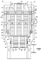
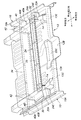
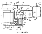
- the floor structure has left and right side sills 10 extending in parallel with each other in the longitudinal direction of the vehicle body, as shown in FIGS.
- the side sill 10 has a closed cross-sectional shape by an inner member 10A and an outer member 10B (see FIGS. 8 and 9) made of a high-strength steel plate (high strength steel plate) having a hat-shaped cross-sectional shape.
- a side sill extension member 11 that connects the side sill 10 and the left and right rear side frames 18 is joined to the rear end of the vehicle body of the side sill 10 (see FIG. 3).
- the left and right edges of the front floor panel 12 disposed between the left and right side sills 10 are joined to the inner member 10A.
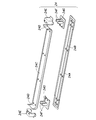
- the floor frame 14 has a hat-shaped cross-sectional shape, is joined to the lower bottom surface (vehicle outer surface) of the front floor panel 12, and forms a closed cross-sectional shape in cooperation with the front floor panel 12.
- the rear ends of the left and right front side frames 16 (see FIGS. 2 and 3) extending in the longitudinal direction of the vehicle body are joined to the vehicle body front ends of the left and right floor frames 14.
- the vehicle body rear ends of the left and right side sills 10 and the left and right floor frames 14 are joined to the front ends of left and right rear side frames 18 (see FIG. 3) that extend in the vehicle body front-rear direction.
- the floor frame 14, the front side frame 16, and the rear side frame 18 each form a skeleton of the vehicle body and form a main transmission path of the collision load in the longitudinal direction of the vehicle body, and are composed of high-tensile steel plates.
- the floor frame 14 has a uniform hat-shaped cross-sectional shape over its entire length and extends in a straight line, so that the transmission of the collision load in the longitudinal direction of the vehicle body can be satisfactorily transmitted without generating a bending moment.
- the floor frame 14 may be joined with a normal steel plate patch member in accordance with the raised height and depression depth of the front floor panel 12, and is closed in cross-section in cooperation with the front floor panel 12 over its entire length. It is possible to have a structure having a shape.
- the front floor panel 12 is made of a pressed steel plate, has a substantially flat panel main surface portion 12A, a tunnel portion 12B that protrudes upward from the panel main surface portion 12A and extends in the vehicle body longitudinal direction in the vehicle width direction, and a tunnel Left and right depressions 12C that are located on the left and right sides of the front side of the vehicle body of the portion 12B and that are recessed below the panel main surface 12A, and both left and right edges (joint edge side with the inner member 10A) are directed toward the depression 12C with a predetermined lateral width And left and right inclined portions 12D inclined downward.
- a plurality of beads 12E extending in the longitudinal direction of the vehicle body are press-formed on the panel main surface portion 12A.
- an upside down pad-shaped upper tunnel member 20 is joined.
- the left and right hollow portions 12C are respectively located on the front side of the vehicle body from an upper first cross member 22 described later, and each serves as a footrest space for a front seat occupant. In addition, if it sees on the basis of the floor height of the hollow part 12C, 12A of panel main surface parts will become a raised floor part.
- the left and right inclined portions 12D are respectively located on the rear side of the vehicle body from an upper first cross member 22 described later, and the side surface on the inner side in the vehicle width direction of the inclined portion 12D is an inclined side surface 12F that is tilted in the vehicle width direction.
- 2, 8, and 9 two bent ridge lines a each extending in the longitudinal direction of the vehicle body at the same position in the vehicle width direction as the position of the floor frame 14 in the vehicle width direction. , B are formed.
- the floor frame 14 forms a polygonal box-shaped cross-sectional shape including the bent ridge lines a and b in cooperation with the front floor panel 12.
- This box-shaped cross-sectional shape improves the rigidity (bending rigidity) of the floor frame 14 in the longitudinal direction of the vehicle body.
- the transmission of the collision load in the longitudinal direction of the vehicle body can be performed satisfactorily without causing bending deformation in the floor frame 14 portion, resulting in a floor structure (vehicle body) that is resistant to front and rear collisions.
- the upper first cross member 22 includes a right end member 22A, a right side member 22B, a tunnel center member 22C, a left side member 22D, and a left end member 22E.
- the foremost portion of the panel main surface portion 12A extends in the vehicle body width direction, and the right end member 22A and the left end member 22E forming the left and right end portions are joined to the inner members 10A of the left and right side sills 10.
- the right end member 22A and the left end member 22E each have a hat-shaped cross section as shown in FIGS. 9 and 10, and connect the inner member 10A of the side sill 10 and the floor frame 14 in the vehicle body width direction.
- the front floor panel 12, the inner member 10A of the side sill 10, and the floor frame 14 are joined to form a closed sectional shape on the front floor panel 12.
- the right member 22B extends on the panel main surface portion 12A in the vehicle body width direction between the right end member 22A and the right outer wall of the tunnel portion 12B, as well shown in FIGS. 1, 2, and 8.
- the front floor panel 12, the right end member 22A, and the right outer wall of the tunnel portion 12B are joined to form a closed cross-sectional shape on the front floor panel 12.
- the left side member 22D extends in the vehicle body width direction on the panel main surface portion 12A between the left end member 22E and the left outer wall of the tunnel portion 12B, as well shown in FIGS.
- the front floor panel 12, the left end member 22E, and the left outer wall of the tunnel portion 12B are joined to form a closed cross-sectional shape on the front floor panel 12.
- the center member 22C in the tunnel has a hat-shaped cross section as well shown in FIGS. 4 and 8, and is located in the tunnel portion 12B and between the right inner wall and the left inner wall of the tunnel portion 12B. It extends in the width direction and is joined to the inner wall of the tunnel portion 12B to form a closed cross-sectional shape at the lower bottom portion (inside the tunnel portion 12B) of the front floor panel 12.
- the right end member 22A and the left end member 22E are configured to have lower strength and lower rigidity (weakness) than the right side member 22B, the tunnel center member 22C, and the left side member 22D.
- the right end member 22A and the left end member 22E are crushed and deformed by a load. It is comprised as a collision energy absorption member (crush member).
- the right member 22B, the tunnel center member 22C, and the left member 22D are set to have strength and rigidity that do not easily deform due to a side collision load.
- each member constituting the upper first cross member 22 can be set according to the shape, thickness, material, etc. of each member constituting the upper first cross member 22 in a divided manner.
- the right end member 22A and the left end member 22E may be made of ordinary steel plates
- the right side member 22B, the tunnel center member 22C, and the left side member 22D may be made of high-tensile steel plates.
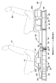
- a lower first cross member 24 is provided which extends to the right and left ends and is joined to the left and right floor frames 14.
- the lower first cross member 24 has a long rectangular lower member 24A formed with a bead 24B, and a long piece having bent piece portions 24D standing at both left and right ends.
- a rectangular upper member 24C, left and right bracket members 24E having a predetermined height, and two cylindrical mounting bolt penetrating collar members 24F each having the same height as the bracket member 24E are welded to the left and right
- the joined body of the lower member 24A and the upper member 24C constitutes a cross member body 25 having a closed cross-sectional shape that is joined to the lower ends of the left and right bracket members 24E and extends horizontally in the vehicle body width direction between the left and right bracket members 24E.
- the bracket member 24E has a hollow cubic shape closed by joining the bent piece 24D and the stiffener 24G.
- the bracket member 24E includes a collar member 24F inside and a lower first cross member from the lower bottom surface of the floor frame 14. 24 droop length is set.
- the lower first cross member 24 is made of a high-strength steel plate for all of the stiffeners 24G except the lower member 24A, the upper member 24C, the bracket member 24E, and the collar member 24F in order to ensure strength and rigidity that are not easily deformed by a side collision load. It is configured. Further, the bracket member 24 has a hollow box shape in cooperation with the bent piece portion 24D, and the collar member 24F having the same height as the bracket member 24E is provided in the bracket member 24E. Thus, the strength and rigidity of the bracket member 24E, particularly the strength in the height direction (vertical direction) is high.
- the vehicle body longitudinal direction position is the same as the vehicle body longitudinal direction position inside the groove of the left and right floor frames 14 and the lower first cross member 24 is disposed.
- the nut support member 26 is joined.
- the nut support member 26 has a groove shape having an upper surface portion 26A parallel to the groove bottom portion 14A of the floor frame 14, and has a welding allowance 26B bent at each side portion (all of the groove opening edge portions). It is welded to the bottom surface and both side surfaces inside the groove 14.
- the upper end portions of two cylindrical nut members 28 are joined to the upper surface portion 26A of the nut support member 26.
- the collar nut member 28 is for fastening the bolt of the bracket member 24E, and is fixed to the upper surface portion 26A through a through hole 26C (see FIGS. 9 and 12) formed in the upper surface portion 26A of the nut support member 26. Then, it hangs down from the upper surface portion 26 ⁇ / b> A into the nut support member 26, and the tip (lower end) is in contact with the groove bottom portion of the floor frame 14.
- the collar nut member 28 is sandwiched between the nut support member 26 and the groove bottom portion of the lower frame 14, and is fixed to the floor frame 14 with high mounting strength.
- There are two color nut members 28 corresponding to the number of collar members 24F, and they are spaced in the longitudinal direction of the vehicle body.
- the nut support member 26 is a mounting mount for attaching the collar nut member 28 to the lower first cross member 24, and reinforcement that reinforces the floor frame 14 in the arrangement portion of the nut support member 26 against a side collision load. Also acts as a member.
- the lower first cross member 24 has left and right floor frames attached to the left and right floor frames by a plurality of (four in total) mounting bolts 30 that pass through the collar member 24F from the lower member 24A side and are screw-engaged with the collar nut member 28. 14 is detachably attached to the lower bottom portion of the body. As a result, the left and right bracket members 24E are respectively fixed to the lower bottom portions of the left and right floor frames 14 and suspended from the lower bottom portions, and the cross member main body 25 is lowered from the lower bottom portions of the floor frame 14 by its own height dimension. Place horizontally horizontally below.
- a height h (see FIG. 5) corresponding to the sum of the height dimension of the floor frame 14 and the height dimension of the bracket member 24E between the panel main surface portion 12A and the upper member 24C of the lower first cross member 24. 9) is provided.
- FIGS. 3 and 4 show the positions in the vehicle front-rear direction between the left and right side sills 10 and the left and right floor frames 14, which are the same as the vehicle front-rear direction positions of the upper first cross member 22 and the lower first cross member 24.
- left and right first outriggers 32 are disposed.
- the upper first cross member 22, the lower first cross member 24, the left and right first outriggers 32, and the left and right nut support members 26 are all arranged at the same position in the longitudinal direction of the vehicle body. That is, they are aligned in a straight line in the vehicle body width direction.
- the first outrigger 32 has a groove shape and has a welding allowance 32A that is bent at each side portion (all of the groove opening edges). 12 is joined to the inner member 10A of the side sill 10 and the side surface of the floor frame 14, and forms a box shape in cooperation with the front floor panel 12 to connect the side sill 10 and the floor frame 14 to each other in the vehicle width direction. ing. As shown in FIGS. 8 and 9, the first outrigger 32 matches the height of the side wall of the inner member 10 ⁇ / b> A at the joint with the inner member 10 ⁇ / b> A, and the side wall of the floor frame 14 at the joint with the floor frame 14. It matches the height.
- the first outrigger 32 has a low strength, low rigidity, and is fragile as compared to the side sill 10 and the floor frame 14.
- the first outrigger 32 is formed of a normal steel plate having a thin plate thickness and is crushed (plastic) by side collision energy. It acts as a collision energy absorbing member (crush member) that deforms.
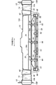
- a second cross member 34 is disposed below the front floor panel 12 at the rear of the vehicle body from the lower first cross member 24.
- the second cross member 34 is made of a high-strength steel plate and has a hat-shaped cross-sectional shape.
- the second cross member 34 extends between the left and right floor frames 14 in a straight line shape in the vehicle body width direction without any vertical difference, and is joined to the lower bottom surface of the front floor panel 12 to cooperate with the front floor panel 12 to have a closed cross section. Make up shape.
- the second cross member 34 is further joined to the left and right floor frames 14 at the left and right ends without any step difference.
- the height (vertical dimension) of the lower first cross member 24 is the height (vertical dimension) of the front floor panel 12. It means that the height of the floor frame 14 from the lower bottom surface of the front floor panel 12 and the height of the second cross member 34 are the same. Also, the fact that the second cross member 34 extends in a straight line with no vertical step means that the second cross member 34 is a flat surface (horizontal surface) of the panel main surface portion 12A, as well shown in FIG. ) Along the vehicle body width direction.
- a nut support member 36 having a hat-shaped cross section is joined over the entire length thereof.
- the nut support member 36 has an upper surface portion 36A that is separated from the groove bottom portion 34A of the second cross member 34 by a predetermined distance and parallel to the groove bottom portion 34A.
- a collar nut member 38 disposed between the groove bottom portion 34A of the second cross member 34 and the upper surface portion 36A of the nut support member 36 is joined (fixed) to the upper surface portion 36A of the nut support member 36.
- a plurality of collar nut members 38 are provided at predetermined intervals in the vehicle width direction.
- the nut support member 36 functions as a reinforcing member for the second cross member 34 together with the support of the collar nut member 38.
- the upper surface portion 36A of the nut support member 36 is preferably at the same height as the height of the center of the cross section of the side sill 10 or the vicinity thereof as a useful reinforcing member.
- the vehicle body longitudinal direction position between the left and right side sills 10 and the left and right floor frames 14 is the same as the vehicle body longitudinal direction position of the second cross member 34.
- left and right second outriggers 40 are disposed. That is, the second cross member 34 and the left and right second outriggers 40 are arranged in a straight line in the vehicle body width direction.
- the second outrigger 40 has a groove shape and has a welding allowance 40A that is bent at each side (all of the groove opening edges) on the lower bottom surface of the front floor panel 12 and the side surfaces of the inner member 10A and the floor frame 14. It is joined and forms a box shape in cooperation with the front floor panel 12. As shown in FIGS. 13 and 14, the second outrigger 40 coincides with the height of the side wall of the inner member 10 ⁇ / b> A at the joint with the inner member 10 ⁇ / b> A in the same manner as the first outrigger 32. At the joint portion, it coincides with the side wall height of the floor frame 14.
- the second outrigger 40 is configured to be weaker and less rigid than the side sill 10 and the floor frame 14.
- the second outrigger 40 is configured by a plain steel plate having a small thickness. And acts as a collision energy absorbing member (crush member) that is crushed (plastically deformed) by side collision energy.
- the vehicle body of the second outrigger 40 is strictly located at the same vehicle longitudinal direction position as the vehicle body longitudinal direction position of the second cross member 34.
- Two flat left and right bulkhead members 42 are joined to the front-rear direction of the vehicle body in the front-rear direction of the front and rear side surface portions 40B.
- the bulkhead member 42 is a substantially quadrilateral plate material, so as to block the groove-shaped section of the floor frame 14 in a direction transverse to the groove-shaped section of the floor frame 14 so as to divide the groove-shaped section of the floor frame 14 forward and backward.
- each side is joined to the inner surface of the groove of the floor frame 14, the groove bottom surface and the lower bottom surface of the front floor panel 12 to close one groove-shaped cross section of the floor frame 14.
- the bulkhead member 42 in this arrangement functions as a reinforcing member that reinforces the floor frame 14 against a side collision load.
- a battery unit 50 is fixedly disposed as shown in FIGS.
- the battery unit 50 is laid with a plurality of vertical frames 52 extending parallel to each other in the longitudinal direction of the vehicle body and without gaps in the longitudinal direction of the vehicle body, and each extending in the width direction of the vehicle body and joined to the adjacent vertical frames 52 at both ends.
- the joint structure of the vertical frame 52 and the horizontal frame 54 is referred to as a battery frame, and the battery frame exists over the entire bottom of the square flat battery unit 50.
- the vertical frame 52 and the horizontal frame 54 may each be constituted by hollow pillars made of aluminum by extrusion to reduce weight, and these may be joined to each other by MIG welding or the like.
- the front portion of the battery unit 50 is disposed between the lower first cross member 24 and the front floor panel 12 having a height h interval, and the lower member 24A.
- the lower first cross member 24 is detachably fixed to the lower first cross member 24 by a plurality of bolts 62 that are threadedly engaged with nut members 60 that pass through the lower first cross member 24 and are fixed to the vertical frame 52.
- the upper first cross member 22 and the lower first cross member 24 connect the left and right floor frames 14 in the vehicle width direction with the battery unit 50 interposed therebetween.
- the middle part of the battery unit 50 in the front-rear direction includes a horizontal frame 54 and a collar member 64 provided between the horizontal frame 54 and the upper cover member 58.
- the collar member 64 is joined (fixed) to the battery frame, in this embodiment, the horizontal frame 54, and is in contact with the lower bottom surface of the second cross member 34 at the tip (upper end). Since the mounting bolt 66 passes through the collar member 64 and is screw-engaged with the nut member 38 supported by the nut support member 36, a rigid screw fastening is achieved. Thereby, the strength and reliability of the suspension support from the second cross member 34 of the battery unit 50 are improved.
- the upper cover member 58 of the battery unit 50 has a groove 59 extending in the vehicle width direction at a portion corresponding to the second cross member 34.
- a collar member 64 is provided at 59, and the second cross member 34 is received in the recessed groove 59 to avoid interference between the battery unit 50 and the second cross member 34.
- the battery unit 50 is bolted to a bracket 68 in which a rear end portion of the vertical frame 52 is detachably fixed to the left and right floor frames 14 by bolts 67.
- the bracket 68 supports the left and right sides of the rear end portion from the left and right floor frames 14.
- another battery unit 80 is provided between the left and right rear side frames 18 at the rear of the vehicle body from the arrangement position of the battery unit 50.
- the battery unit 80 is laid with a plurality of vertical frames 82 extending in parallel with each other in the longitudinal direction of the vehicle body and without gaps in the longitudinal direction of the vehicle body, and extends in the vehicle body width direction and is adjacent to both ends.
- a horizontal frame 84 joined to the vertical frame 82, a plurality of battery main bodies 86 installed on the horizontal frame 84, and an upper cover member 88 that is attached to the upper portion of the vertical frame 82 and accommodates the battery main body 86 therein. It is comprised by.
- An outer frame 90 is fixed to the vertical frame 82 located on the left and right sides.
- the vertical frame 82 and the horizontal frame 84 may each be constituted by hollow pillars made of aluminum by extrusion to reduce weight, and these may be joined together by MIG welding or the like.
- a rear cross member 92 is provided between the left and right rear side frames 18, extending in the vehicle body width direction and having left and right ends joined to the left and right rear side frames 18. .
- Brackets 94 are attached to the left and right sides of the rear cross member 92. As shown in FIGS. 14 and 15, the bracket 94 is bolted to the outer frame 90 and supports the battery unit 80 in a detachable manner.
- a battery control unit 74 is installed in the internal space of the upper tunnel member 20.
- a front seat FS is disposed on the upper tunnel member 20.
- a rear floor panel 48 is connected to the rear of the vehicle body of the front floor panel 12.
- the rear seat RS is disposed on the raised portion 48 ⁇ / b> A of the rear floor panel 48.
- the first outrigger 32 coincides with the side wall height of the inner member 10A at the joint portion with the inner member 10A, and coincides with the side wall height of the floor frame 14 at the joint portion with the floor frame 14, so that the entire height is increased.
- the side collision load is received as a compression load.
- the first outrigger 32 inputs a side collision load from the entire height direction of the side wall of the side sill 10 in a state where the reaction force is received over the entire height direction of the side wall of the floor frame 14.
- the entire first outrigger 32 is effectively crushed. Thereby, the absorbable amount of collision energy between the side sill 10 and the floor frame 10 by the first outrigger 32 is improved. Thereby, deformation of the floor frame 14 is highly avoided.
- the second outrigger 40 matches the side wall height of the inner member 10A at the joint portion with the inner member 10A, and matches the side wall height of the floor frame 14 at the joint portion with the floor frame 14. Receives side impact loads as compression loads throughout the height. That is, the second outrigger 40 also receives a side collision load from the entire height direction of the side wall of the side sill 10 in a state where the reaction force is received over the entire height direction of the side wall of the floor frame 14. The entire second outrigger 40 is effectively crushed. Thereby, the absorbable amount of collision energy between the side sill 10 and the floor frame 10 by the second outrigger 32 is also improved. Also by this, deformation of the floor frame 14 is highly avoided.
- the side collision load input to the floor frame 14 after the second outrigger 40 is crushed is split up and down into the upper first cross member 22 and the lower first cross member 24, and both are separated from one floor frame 14. To the floor frame 14.
- the upper first cross member 22 arranged in the vehicle interior can be made smaller than the conventional one, and the vehicle body can be downsized and the vehicle interior can be reduced.
- the living space can be expanded.
- the right end member 22A and the left end member 22E of the upper first cross member 22 have lower strength than the lower first cross member 24 and act as a collision energy absorbing member that is crushed by a side collision load.
- the ratio of the side collision load input to the first cross member 22 and the side collision load input to the lower first cross member 24 can be set to an optimum specification.
- the lower first cross member 24 has a cross member body with a closed cross-sectional shape and high rigidity, the collar member 24F is used to increase the rigidity of the bracket member 24E, and the bolt of the bracket member 24E.
- the upper portion of the fastening collar nut member 28 is fixed to a nut support member 26 joined to the floor frame 14 and the mounting strength of the collar nut member 28 with respect to the floor frame 14 is strengthened.
- the tolerance value is high. That is, the lower first cross member 24 is entirely robust and is not easily deformed by a side collision load. Thereby, the allowable transmission value of the side collision load by the lower first cross member 24 is increased, and the allowable input amount of the side collision load to the lower first cross member 24 can be increased.
- the first outrigger 32 including after the first outrigger 32 is crushed is used.
- the transmission of the side collision load from the side sill 10 to the floor frame 14, the upper first cross member 22, and the lower first cross member 24 is performed linearly and satisfactorily. This also makes it difficult for the floor frame 14 to deform.
- the second cross member 34 extends in a straight line in the vehicle body width direction without vertical steps, and the left and right ends are joined to the left and right floor frames 14 without vertical steps, the left and right sides of the second cross member 34
- the transmission of the side collision load between the floor frames 14 is also favorably performed without generating a bending moment in the second cross member 34. This reliably and highly avoids deformation of the floor frame 14 on the side collision load input side. This also prevents a collision load from acting on the battery unit 50 disposed between the left and right floor frames 14, and the battery unit 50 is reliably protected against a side collision.
- the nut support member 36 acts as a reinforcing member for the second cross member 34 together with the support of the collar nut member 38, the second strength member is secured with sufficient strength and rigidity for protecting the battery unit 50.
- the cross section of the cross member 34 can be reduced. Thereby, the miniaturization design of a vehicle body is attained, and a vehicle body weight can also be reduced. Further, since the support strength of the collar nut member 38 is improved, the support strength of the battery unit 50 is also increased.
- the second cross member 34 does not cause the side sill 10 to fall down and the nut support member.
- the side collision load can be received in a planar shape by the upper surface portion 36A of 36, and the side collision load can be received in a planar shape, and the transmission of the side collision load by the second cross member 34 can be performed efficiently and satisfactorily. Will come to be.
- the provision of the bulkhead member 42 effectively improves the strength and rigidity of the floor frame 14 at the side collision load transmitting portion to the second cross member 34, and the entire cross section of the second cross member 34 is improved.
- the side collision load can be transmitted well.
- the battery unit 50 can be attached and detached by removing the lower first cross member 24 from the floor frame 14 by removing the mounting bolt 30, removing the mounting bolt 66, and removing the brat 68 from the floor frame 14 by removing the bolt 67.
- the entire first cross member 24 can be carried out from below the front floor panel 12.
- the battery unit 50 can be easily attached / detached and replaced from under the vehicle floor after the battery unit 50 is reliably protected against the side collision.
- the front floor panel 12 has recesses 12C that are recessed below the panel main surface 12A on the left and right sides of the tunnel portion 12B on the front side of the vehicle body from the upper first cross member 22. Therefore, the recess 12C can be secured regardless of the arrangement of the battery unit 50 below the floor.
- the recessed portion 12C becomes a footrest space for the front seat occupant seated on the front seat FS, and does not excessively increase the arrangement height of the front seat FS, that is, without deteriorating the ease of getting on and off. You can ease your posture.
- the flat panel main surface portion 12A on which the second cross member 34 is arranged is secured in front of the rear seat RS regardless of the arrangement of the battery unit 50 below the floor, the rear seat occupant seated on the rear seat RS Good footrest space for can be secured.
- the seating posture can be eased and the side collision load can be efficiently transmitted linearly by the second cross member 34.
- the left and right bracket members 24E of the lower first cross member 24 are not necessarily required. If the height h is shortened by reducing the thickness of the battery unit 50, the lower first cross member 24 may be connected to the lower member 24A and the upper member. It may be constituted only by a polymer with 24C, that is, the cross member main body 25.
Abstract
Description
10A インナメンバ
10B アウタメンバ
11 サイドシルエクステンションメンバ
12 フロントフロアパネル
12A パネル主面部
12B トンネル部
12C 窪み部
12D 傾斜部
12F 傾斜側面
14 フロアフレーム
16 フロントサイドフレーム
18 リアサイドフレーム
20 アッパトンネルメンバ
22 上部第1クロスメンバ
22A 右端部材
22B 右側部材
22C トンネル内中央部材
22D 左側部材
22E 左端部材
24 下部第1クロスメンバ
24A ロワーメンバ
24C アッパメンバ
24E ブラケット部材
24F カラー部材
25 クロスメンバ本体
26 ナットサポート部材
28 カラー部材
30 ボルト
32 第1アウトリガ
34 第2クロスメンバ
36 ナットサポート部材
38 カラーナット部材
48 リアフロアパネル
40 第2アウトリガ
42 バルクヘッドメンバ
50 バッテリユニット
68 ブラケット
80 バッテリユニット
92 リアクロスメンバ DESCRIPTION OF
Claims (17)
- 車体前後方向に延在する左右のサイドシルと、前記左右のサイドシル間に配置されたフロントフロアパネルと、前記フロントフロアパネルの下側で前記左右のサイドシルより車体幅方向の内側を各々車体前後方向に延在する左右のフロアフレームとを有し、前記フロントフロアパネルの下側の前記左右のフロアフレーム間にバッテリユニットを配置される自動車のフロア構造であって、
車体幅方向に延在して両端を前記左右のサイドシルに接合された上部第1クロスメンバと、
前記フロントフロアパネルの下側で前記上部第1クロスメンバの下方位置を車体幅方向に延在して両端を前記左右のフロアフレームに固定され、前記上部第1クロスメンバとで前記バッテリユニットを上下に挟む下部第1クロスメンバと、
を有する自動車のフロア構造。 Left and right side sills extending in the longitudinal direction of the vehicle body, a front floor panel disposed between the left and right side sills, and an inner side in the vehicle width direction from the left and right side sills below the front floor panel, respectively in the longitudinal direction of the vehicle body A floor structure of an automobile having left and right floor frames extending, wherein a battery unit is disposed between the left and right floor frames below the front floor panel,
An upper first cross member extending in the vehicle body width direction and having both ends joined to the left and right side sills;
The lower position of the upper first cross member extends in the vehicle body width direction below the front floor panel and both ends are fixed to the left and right floor frames, and the battery unit is moved up and down with the upper first cross member. A lower first cross member sandwiched between,
An automobile floor structure having - 前記上部第1クロスメンバと前記下部第1クロスメンバとは車体前後方向に同じ位置にあり、更にこれらと車体前後方向に同じ位置に、前記サイドシルと前記フロアフレームとの間にあって当該両者に接合されて側部衝突エネルギにより圧潰する第1アウトリガが配置されている請求項1に記載の自動車のフロア構造。 The upper first cross member and the lower first cross member are at the same position in the longitudinal direction of the vehicle body, and further, at the same position in the longitudinal direction of the vehicle body, between the side sill and the floor frame and joined to both. The automobile floor structure according to claim 1, wherein a first outrigger that is crushed by side collision energy is disposed.
- 前記第1アウトリガは、前記サイドシルとの接合部では当該サイドシルの側壁高さに一致し、前記フロアフレームとの接合部では当該フロアフレームの側壁高さに一致している請求項2に記載の自動車のフロア構造。 The automobile according to claim 2, wherein the first outrigger coincides with a side wall height of the side sill at a joint portion with the side sill, and coincides with a side wall height of the floor frame at a joint portion with the floor frame. Floor structure.
- 上部第1クロスメンバは、前記サイドシルと前記フロアフレームとの間に延在する部分の強度が、それより車体幅方向内側に延在する部分の強度より低い請求項1から3の何れか一項に記載の自動車のフロア構造。 4. The upper first cross member according to claim 1, wherein the strength of the portion extending between the side sill and the floor frame is lower than the strength of the portion extending inward in the vehicle width direction. 5. The automobile floor structure described in 1.
- 前記下部第1クロスメンバは、各々前記左右のフロアフレームの下底部に固定されて当該下底部より垂下した左右のブラケット部材と、前記左右のブラケット部材の下端に接合されて前記左右のブラケット部材間を車体幅方向に延在するクロスメンバ本体とを有し、ブラケット部材は、中空箱形をなし、内部に取付ボルトが貫通するカラー部材が固定配置されている請求項1から4の何れか一項に記載の記載の自動車のフロア構造。 The lower first cross members are respectively fixed to the lower bottoms of the left and right floor frames and joined to the left and right bracket members hanging from the lower bottoms, and joined to the lower ends of the left and right bracket members. And a cross member body extending in the vehicle body width direction, the bracket member has a hollow box shape, and a collar member through which a mounting bolt passes is fixedly disposed. The automobile floor structure according to the item.
- 前記フロアフレームは溝形断面形状を含み、その溝内側に、前記ブラケット部材のボルト締結用のカラーナット部材の上部を支持するサポート部材が接合されている請求項5に記載の自動車のフロア構造。 The automobile floor structure according to claim 5, wherein the floor frame includes a groove-shaped cross-sectional shape, and a support member that supports an upper portion of a collar nut member for fastening the bolt of the bracket member is joined to the inside of the groove.
- 前記クロスメンバ本体は、ロワーメンバとアッパメンバとの接合体により構成され、閉じ断面形状をなしている請求項5または6に記載の自動車のフロア構造。 The automobile floor structure according to claim 5 or 6, wherein the cross member body is constituted by a joined body of a lower member and an upper member and has a closed cross-sectional shape.
- 前記下部第1クロスメンバは前記左右のフロアフレームに着脱可能に固定され、当該下部第1クロスメンバに前記バッテリユニットが固定されている請求項1から7の何れか一項に記載の記載の自動車のフロア構造。 The automobile according to any one of claims 1 to 7, wherein the lower first cross member is detachably fixed to the left and right floor frames, and the battery unit is fixed to the lower first cross member. Floor structure.
- 前記下部第1クロスメンバより車体後方位置において前記フロントフロアパネルの下側を車体幅方向に延在して両端を前記左右のフロアフレームに接合され、溝形断面部を含む形状の第2クロスメンバと、
前記第2クロスメンバの全長に亘って延在して前記溝形断面部内に接合され、前記第2クロスメンバの溝底部より上方に所定距離だけ離れて溝底部と平行な上面部を有するナットサポート部材と、
前記第2クロスメンバの溝底部と前記ナットサポート部材の前記上面部との間に延在し、車幅方向に所定間隔をおいて配置されて前記ナットサポート部材の前記上面部に固定された複数個のカラーナット部材とを有し、
前記カラーナット部材にねじ係合する取付ボルトによって前記バッテリユニットが前記フロントフロアパネルの下側に固定されている請求項1から8の何れか一項に記載の自動車のフロア構造。 A second cross member having a shape in which a lower side of the front floor panel extends in the vehicle body width direction from the lower first cross member in the vehicle body width direction, both ends are joined to the left and right floor frames, and includes a groove-shaped cross section. When,
A nut support that extends over the entire length of the second cross member and is joined to the groove-shaped cross-section, and has a top surface that is spaced a predetermined distance above the groove bottom of the second cross member and parallel to the groove bottom. Members,
A plurality of portions extending between a groove bottom portion of the second cross member and the upper surface portion of the nut support member, arranged at a predetermined interval in the vehicle width direction and fixed to the upper surface portion of the nut support member. A plurality of collar nut members,
The automobile floor structure according to any one of claims 1 to 8, wherein the battery unit is fixed to a lower side of the front floor panel by a mounting bolt that is screw-engaged with the collar nut member. - 前記第2クロスメンバは前記左右のフロアフレーム間を上下段差なく一直線状に延在している請求項9に記載の自動車のフロア構造。 The automobile floor structure according to claim 9, wherein the second cross member extends in a straight line between the left and right floor frames without any step difference.
- 前記ナットサポート部材の前記上面部は前記サイドシルの断面中央あるいはその近傍の高さと同じ高さにある請求項9または10に記載の自動車のフロア構造。 The automobile floor structure according to claim 9 or 10, wherein the upper surface portion of the nut support member is at the same height as the height of the cross-sectional center of the side sill or the vicinity thereof.
- 前記第2クロスメンバと車体前後方向で見て同じ位置に、前記サイドシルと前記フロアフレームの間に当該両者に接合して側部衝突エネルギにより圧潰する第2アウトリガが配置されている請求項9から11の何れか一項に記載の自動車のフロア構造。 The second outrigger that is joined to both the side sill and the floor frame and is crushed by side collision energy is disposed at the same position when viewed in the longitudinal direction of the vehicle body from the second cross member. The automobile floor structure according to claim 11.
- 前記第2アウトリガは、前記サイドシルとの接合部では当該サイドシルの側壁高さに一致し、前記フロアフレームとの接合部では当該前記フロアフレームの側壁高さに一致している請求項12に記載の自動車のフロア構造。 13. The second outrigger according to claim 12, wherein the second outrigger coincides with a side wall height of the side sill at a joint portion with the side sill, and coincides with a side wall height of the floor frame at a joint portion with the floor frame. Car floor structure.
- 前記フロアフレーム内に、前記第2クロスメンバの車体前後方向位置と同じ車体前後方向位置に、当該フロアフレームの溝形断面を塞ぐように延在して当該溝形断面を閉じる板状のバルクヘッドメンバが接合されている請求項9から13の何れか一項に記載の自動車のフロア構造。 A plate-shaped bulkhead that extends in the floor frame to close the groove-shaped cross section of the floor frame at the same position in the vehicle longitudinal direction as the position of the second cross member in the vehicle longitudinal direction. The automobile floor structure according to any one of claims 9 to 13, wherein the members are joined.
- 前記バッテリユニットは底部にバッテリフレームを有し、前記バッテリフレームには、先端にて前記第2クロスメンバと当接し、前記取付ボルトが貫通するカラー部材が接合している請求項9から14の何れか一項に記載の自動車のフロア構造。 15. The battery unit according to claim 9, wherein the battery unit has a battery frame at the bottom, and a collar member that contacts the second cross member at the tip and through which the mounting bolt passes is joined to the battery frame. The automobile floor structure according to claim 1.
- 前記フロントフロアパネルは、パネル主面部と、前記パネル主面部より上方に隆起して車体幅方向の中央部を車体前後方向に延在するトンネル部と、前記上部第1クロスメンバより車体前側の前記トンネル部の左右両側にあって前記パネル主面部より下方に陥没した窪み部とを有し、前記窪み部より車体後方に前記バッテリユニットを配置された請求項1から15の何れか一項に記載の自動車のフロア構造。 The front floor panel includes a panel main surface portion, a tunnel portion that protrudes upward from the panel main surface portion and extends in the vehicle body longitudinal direction in the vehicle body width direction, and the vehicle body front side of the upper first cross member. 16. The battery unit according to claim 1, further comprising: a recessed portion which is located on both left and right sides of the tunnel portion and is depressed below the panel main surface portion, and wherein the battery unit is disposed rearward of the vehicle body from the recessed portion. Car floor structure.
- 前記フロントフロアパネルは、前記上部第1クロスメンバより車体後方部において前記左右のフロアフレームの配置位置に、当該フロアフレームの延在方向に同方向に延在する折曲稜線を形成する傾斜部を有する請求項1から16の何れか一項に記載の自動車のフロア構造。 The front floor panel has an inclined portion that forms a bent ridge line extending in the same direction in the extending direction of the floor frame at the arrangement position of the left and right floor frames at the rear portion of the vehicle body from the upper first cross member. The automobile floor structure according to any one of claims 1 to 16.
Priority Applications (4)
| Application Number | Priority Date | Filing Date | Title |
|---|---|---|---|
| BR112013011355A BR112013011355A2 (en) | 2010-11-10 | 2011-09-15 | automotive floor structure |
| EP11840435.9A EP2620353B1 (en) | 2010-11-10 | 2011-09-15 | Automobile floor structure |
| US13/823,800 US8939246B2 (en) | 2010-11-10 | 2011-09-15 | Automotive floor structure |
| JP2012542790A JP5654039B2 (en) | 2010-11-10 | 2011-09-15 | Car floor structure |
Applications Claiming Priority (6)
| Application Number | Priority Date | Filing Date | Title |
|---|---|---|---|
| JP2010252070 | 2010-11-10 | ||
| JP2010-252071 | 2010-11-10 | ||
| JP2010252071 | 2010-11-10 | ||
| JP2010252065 | 2010-11-10 | ||
| JP2010-252065 | 2010-11-10 | ||
| JP2010-252070 | 2010-11-10 |
Publications (1)
| Publication Number | Publication Date |
|---|---|
| WO2012063393A1 true WO2012063393A1 (en) | 2012-05-18 |
Family
ID=46050566
Family Applications (1)
| Application Number | Title | Priority Date | Filing Date |
|---|---|---|---|
| PCT/JP2011/005214 WO2012063393A1 (en) | 2010-11-10 | 2011-09-15 | Automobile floor structure |
Country Status (5)
| Country | Link |
|---|---|
| US (1) | US8939246B2 (en) |
| EP (1) | EP2620353B1 (en) |
| JP (1) | JP5654039B2 (en) |
| BR (1) | BR112013011355A2 (en) |
| WO (1) | WO2012063393A1 (en) |
Cited By (43)
| Publication number | Priority date | Publication date | Assignee | Title |
|---|---|---|---|---|
| US20120160088A1 (en) * | 2010-12-22 | 2012-06-28 | Tesla Motors, Inc. | Vehicle Battery Pack Ballistic Shield |
| WO2013053433A1 (en) * | 2011-10-12 | 2013-04-18 | Volkswagen Aktiengesellschaft | Assembly structure for an electrically driven passenger motor vehicle |
| EP2685523A1 (en) * | 2012-07-13 | 2014-01-15 | Mitsubishi Jidosha Kogyo Kabushiki Kaisha | Battery pack tray |
| US8696051B2 (en) | 2010-12-22 | 2014-04-15 | Tesla Motors, Inc. | System for absorbing and distributing side impact energy utilizing a side sill assembly with a collapsible sill insert |
| EP2741343A1 (en) * | 2012-12-04 | 2014-06-11 | Mitsubishi Jidosha Kogyo K.K. | Battery pack with housing and reinforcement fittings and attachement members for a vehicle |
| US8875828B2 (en) | 2010-12-22 | 2014-11-04 | Tesla Motors, Inc. | Vehicle battery pack thermal barrier |
| JP2015074244A (en) * | 2013-10-04 | 2015-04-20 | トヨタ自動車株式会社 | Car body frame and vehicle underfloor structure |
| DE102014115090A1 (en) | 2013-10-17 | 2015-04-23 | Fuji Jukogyo Kabushiki Kaisha | MOUNTING ARRANGEMENT FOR A BATTERY GROUP |
| US9045030B2 (en) | 2010-12-22 | 2015-06-02 | Tesla Motors, Inc. | System for absorbing and distributing side impact energy utilizing an integrated battery pack |
| US9061712B2 (en) | 2011-07-08 | 2015-06-23 | Thyssenkrupp Steel Europe Ag | Understructure for a vehicle |
| JP2015150927A (en) * | 2014-02-12 | 2015-08-24 | 日産自動車株式会社 | On-vehicle structure of battery |
| JP2016164051A (en) * | 2015-03-06 | 2016-09-08 | トヨタ自動車株式会社 | Battery unit mounting structure |
| JP2017081201A (en) * | 2015-10-22 | 2017-05-18 | 本田技研工業株式会社 | Vehicle body side part structure |
| CN107078247A (en) * | 2014-10-24 | 2017-08-18 | 爱信轻金属株式会社 | Protecting frame tectosome |
| JP2017193289A (en) * | 2016-04-21 | 2017-10-26 | トヨタ自動車株式会社 | Battery-mounting structure for vehicle |
| JP2017193299A (en) * | 2016-04-22 | 2017-10-26 | トヨタ自動車株式会社 | Battery-mounting structure for vehicle |
| JP2017222345A (en) * | 2016-06-13 | 2017-12-21 | ドクター エンジニール ハー ツェー エフ ポルシェ アクチエンゲゼルシャフトDr. Ing. h.c. F. Porsche Aktiengesellschaft | Battery housing for traction battery in automobile |
| JP2018012354A (en) * | 2016-07-19 | 2018-01-25 | トヨタ自動車株式会社 | Battery case |
| KR20180091010A (en) * | 2015-12-09 | 2018-08-14 | 아르셀러미탈 | A vehicle underbody structure comprising a transverse beam whose plastic deformation is variable |
| JP2018131061A (en) * | 2017-02-15 | 2018-08-23 | スズキ株式会社 | Structure of side sill part |
| JP2018131136A (en) * | 2017-02-17 | 2018-08-23 | 本田技研工業株式会社 | Vehicle body lower part structure |
| JP2018131060A (en) * | 2017-02-15 | 2018-08-23 | スズキ株式会社 | Structure of side sill part |
| WO2018163815A1 (en) * | 2017-03-10 | 2018-09-13 | マツダ株式会社 | Lower vehicle body structure for vehicle |
| JP2018161934A (en) * | 2017-03-24 | 2018-10-18 | 三菱自動車工業株式会社 | Floor structure of vehicle body |
| WO2018216614A1 (en) * | 2017-05-22 | 2018-11-29 | 本田技研工業株式会社 | Structure for lower part of vehicle body |
| CN109291768A (en) * | 2017-07-25 | 2019-02-01 | 丰田自动车株式会社 | Structure for side portion of vehicle |
| CN109565010A (en) * | 2016-08-11 | 2019-04-02 | 蒂森克虏伯钢铁欧洲股份公司 | Battery case |
| JP2019127054A (en) * | 2018-01-22 | 2019-08-01 | トヨタ自動車株式会社 | Vehicle lower structure |
| JP2019130978A (en) * | 2018-01-30 | 2019-08-08 | トヨタ自動車株式会社 | Vehicle floor structure |
| JP2019155965A (en) * | 2018-03-07 | 2019-09-19 | トヨタ自動車株式会社 | Vehicular body structure |
| JP2020032738A (en) * | 2018-08-27 | 2020-03-05 | トヨタ自動車株式会社 | Vehicle lower part structure |
| JP2020097349A (en) * | 2018-12-19 | 2020-06-25 | スズキ株式会社 | Vehicle lower part structure |
| CN111661171A (en) * | 2019-03-06 | 2020-09-15 | 马自达汽车株式会社 | Lower body structure of vehicle |
| EP3738863A1 (en) | 2019-05-15 | 2020-11-18 | Mazda Motor Corporation | Lower vehicle-body structure of electric vehicle |
| EP3738864A1 (en) | 2019-05-15 | 2020-11-18 | Mazda Motor Corporation | Lower vehicle-body structure of an electric vehicle, vehicle-body structure of an electric vehicle, and electric vehicle |
| EP3741652A1 (en) | 2019-05-15 | 2020-11-25 | Mazda Motor Corporation | Lower vehicle-body structure of an electric vehicle, vehicle-body structure of an electric vehicle, and electric vehicle |
| KR20210007902A (en) * | 2019-07-11 | 2021-01-20 | 도요타 지도샤(주) | Vehicle |
| JP2021113006A (en) * | 2020-01-21 | 2021-08-05 | 本田技研工業株式会社 | Floor structure of vehicle |
| JP2021113007A (en) * | 2020-01-21 | 2021-08-05 | 本田技研工業株式会社 | Floor structure of vehicle |
| JP2021138228A (en) * | 2020-03-03 | 2021-09-16 | トヨタ自動車株式会社 | Vehicle lower part structure |
| WO2022224959A1 (en) * | 2021-04-19 | 2022-10-27 | 三菱自動車工業株式会社 | Lower structure for vehicle |
| JP2022172931A (en) * | 2021-05-07 | 2022-11-17 | 株式会社神戸製鋼所 | Vehicle body structure for electric vehicle |
| EP4098523A1 (en) * | 2021-06-01 | 2022-12-07 | Mazda Motor Corporation | Vehicle-body structure of electric automotive vehicle |
Families Citing this family (92)
| Publication number | Priority date | Publication date | Assignee | Title |
|---|---|---|---|---|
| US9022152B2 (en) * | 2010-12-24 | 2015-05-05 | Honda Motor Co., Ltd. | Automobile body structure |
| JP5477322B2 (en) * | 2011-04-01 | 2014-04-23 | マツダ株式会社 | Vehicle electrical component arrangement structure |
| US8925991B2 (en) * | 2011-06-08 | 2015-01-06 | Ford Global Technologies, Llc | Reinforced frame-to-body attachment |
| JP5734453B2 (en) * | 2011-11-14 | 2015-06-17 | 本田技研工業株式会社 | Battery built-in structure |
| JP5880086B2 (en) * | 2012-01-31 | 2016-03-08 | 三菱自動車工業株式会社 | Battery container |
| JP6168139B2 (en) * | 2013-02-20 | 2017-07-26 | トヨタ自動車株式会社 | Body structure |
| DE102013004793A1 (en) * | 2013-03-20 | 2014-09-25 | GM Global Technology Operations LLC (n. d. Ges. d. Staates Delaware) | Floor structure of a motor vehicle body |
| JP5900481B2 (en) * | 2013-12-25 | 2016-04-06 | トヨタ自動車株式会社 | Vehicle panel structure |
| JP5870992B2 (en) * | 2013-12-25 | 2016-03-01 | トヨタ自動車株式会社 | Battery mounting structure for vehicles |
| KR101506422B1 (en) * | 2014-04-16 | 2015-03-27 | 지엠 글로벌 테크놀러지 오퍼레이션스 엘엘씨 | An apparatus for protecting the batteries of an electronic vehicle |
| FR3020613B1 (en) * | 2014-05-05 | 2016-04-29 | Peugeot Citroen Automobiles Sa | DOOR THRESHOLDING ELEMENT OF A MOTOR VEHICLE |
| DE102014107388A1 (en) * | 2014-05-26 | 2015-11-26 | Dr. Ing. H.C. F. Porsche Aktiengesellschaft | Underbody unit for a motor vehicle |
| DE102014108160A1 (en) * | 2014-06-11 | 2015-12-17 | Dr. Ing. H.C. F. Porsche Aktiengesellschaft | Underbody unit for a motor vehicle |
| FR3026682B1 (en) * | 2014-10-02 | 2016-11-18 | Peugeot Citroen Automobiles Sa | EMBROIDERED TOOL ASSEMBLY FOR SUPPORTING THE BATTERY OF AN ELECTRIC OR HYBRID VEHICLE HAVING A STIFFENER |
| US9505442B2 (en) | 2015-03-05 | 2016-11-29 | Ford Global Technologies, Llc | Energy absorbing rocker assembly |
| US10358169B2 (en) * | 2015-03-06 | 2019-07-23 | Ford Global Technologies, Llc | Coverless battery assembly for electrified vehicle |
| US9694854B2 (en) * | 2015-03-27 | 2017-07-04 | Ford Global Technologies, Llc | Vehicle structural reinforcing device |
| FR3038288B1 (en) * | 2015-07-02 | 2017-07-28 | Peugeot Citroen Automobiles Sa | FLOOR OF MOTOR VEHICLE |
| DE102015112138A1 (en) * | 2015-07-24 | 2017-01-26 | Dr. Ing. H.C. F. Porsche Aktiengesellschaft | Underbody of an electrically driven motor vehicle |
| US9533600B1 (en) | 2015-09-03 | 2017-01-03 | GM Global Technology Operations LLC | Structurally integrated propulsion battery |
| JP6235621B2 (en) * | 2016-01-12 | 2017-11-22 | 本田技研工業株式会社 | Auto body structure |
| JP6605347B2 (en) * | 2016-02-04 | 2019-11-13 | 本田技研工業株式会社 | 4 wheel vehicle |
| DE102016203209B4 (en) | 2016-02-29 | 2020-11-19 | Ford Global Technologies, Llc | At least partially electrically operated motor vehicle |
| DE102016203210A1 (en) | 2016-02-29 | 2017-08-31 | Ford Global Technologies, Llc | At least partially electrically operable motor vehicle |
| JP6512162B2 (en) * | 2016-04-21 | 2019-05-15 | トヨタ自動車株式会社 | Vehicle battery mounting structure |
| JP6520808B2 (en) * | 2016-04-21 | 2019-05-29 | トヨタ自動車株式会社 | Vehicle battery mounting structure |
| JP6540588B2 (en) * | 2016-04-28 | 2019-07-10 | トヨタ自動車株式会社 | Vehicle battery mounting structure |
| KR101795399B1 (en) * | 2016-06-22 | 2017-11-10 | 현대자동차 주식회사 | Under body for electric vehicle |
| WO2018033880A2 (en) | 2016-08-17 | 2018-02-22 | Shape Corp. | Battery support and protection structure for a vehicle |
| US10343554B2 (en) * | 2016-09-07 | 2019-07-09 | Thunder Power New Energy Vehicle Development Company Limited | Seat rail |
| US20180065461A1 (en) * | 2016-09-07 | 2018-03-08 | Thunder Power New Energy Vehicle Development Company Limited | Cross member in the floor with special geometry for mounting the battery pack |
| US10308290B1 (en) | 2016-09-20 | 2019-06-04 | Apple Inc. | Vehicle floor and subassemblies thereof |
| US10431791B2 (en) * | 2016-11-01 | 2019-10-01 | Ford Global Technologies, Llc | Traction battery pack shield and shielding method |
| US10381621B2 (en) * | 2016-11-01 | 2019-08-13 | Ford Global Technologies, Llc | Traction battery energy absorbing method and assembly |
| KR101896336B1 (en) * | 2016-11-16 | 2018-09-07 | 현대자동차 주식회사 | Reinforcement unit of side sill for electric vehicles |
| KR102506842B1 (en) * | 2016-11-17 | 2023-03-08 | 현대자동차주식회사 | Battery support structure of vehicle body |
| JP6555235B2 (en) * | 2016-11-30 | 2019-08-07 | トヨタ自動車株式会社 | Lower body structure |
| US11214137B2 (en) | 2017-01-04 | 2022-01-04 | Shape Corp. | Vehicle battery tray structure with nodal modularity |
| DE102017206988A1 (en) | 2017-04-26 | 2018-10-31 | Mahle Lnternational Gmbh | accumulator |
| DE102017206986A1 (en) * | 2017-04-26 | 2018-10-31 | Mahle International Gmbh | accumulator |
| JP6977307B2 (en) * | 2017-04-28 | 2021-12-08 | トヨタ自動車株式会社 | Vehicle undercarriage |
| JP6977309B2 (en) * | 2017-04-28 | 2021-12-08 | トヨタ自動車株式会社 | Vehicle undercarriage |
| WO2018213306A1 (en) | 2017-05-16 | 2018-11-22 | Shape Corp. | Vehicle battery tray having tub-based component |
| US11211656B2 (en) | 2017-05-16 | 2021-12-28 | Shape Corp. | Vehicle battery tray with integrated battery retention and support feature |
| WO2018213475A1 (en) | 2017-05-16 | 2018-11-22 | Shape Corp. | Polarized battery tray for a vehicle |
| JP6596466B2 (en) * | 2017-06-06 | 2019-10-23 | 株式会社Subaru | Vehicle panel structure |
| US10556624B2 (en) * | 2017-06-16 | 2020-02-11 | Ford Global Technologies, Llc | Vehicle underbody component protection assembly |
| JP6541724B2 (en) * | 2017-07-10 | 2019-07-10 | 株式会社Subaru | Car vehicle |
| JP6977361B2 (en) * | 2017-07-24 | 2021-12-08 | スズキ株式会社 | Vehicle undercarriage |
| WO2019055658A2 (en) | 2017-09-13 | 2019-03-21 | Shape Corp. | Vehicle battery tray with tubular peripheral wall |
| DE112018005556T5 (en) | 2017-10-04 | 2020-06-25 | Shape Corp. | BATTERY RACK FLOOR ASSEMBLY FOR ELECTRIC VEHICLES |
| JP6859933B2 (en) * | 2017-11-17 | 2021-04-14 | トヨタ自動車株式会社 | Vehicle battery case and its manufacturing method |
| KR102474370B1 (en) * | 2018-01-08 | 2022-12-05 | 현대자동차 주식회사 | Side vehicle body reinforcing structure |
| EP3759761A4 (en) | 2018-03-01 | 2021-09-08 | Shape Corp. | Cooling system integrated with vehicle battery tray |
| JP6988590B2 (en) * | 2018-03-09 | 2022-01-05 | トヨタ自動車株式会社 | Vehicle rear structure |
| JP7006390B2 (en) * | 2018-03-09 | 2022-01-24 | トヨタ自動車株式会社 | Vehicle lower body structure |
| US11688910B2 (en) | 2018-03-15 | 2023-06-27 | Shape Corp. | Vehicle battery tray having tub-based component |
| JP6724061B2 (en) * | 2018-04-18 | 2020-07-15 | 本田技研工業株式会社 | Battery pack |
| JP6757362B2 (en) * | 2018-05-25 | 2020-09-16 | 本田技研工業株式会社 | Body undercarriage |
| JP6662953B2 (en) * | 2018-05-25 | 2020-03-11 | 本田技研工業株式会社 | Lower body structure |
| JP7035832B2 (en) | 2018-06-13 | 2022-03-15 | トヨタ自動車株式会社 | Vehicle undercarriage |
| DE102018210121A1 (en) * | 2018-06-21 | 2019-12-24 | Volkswagen Aktiengesellschaft | Battery housing and motor vehicle with such a battery housing |
| US10780923B2 (en) * | 2018-07-13 | 2020-09-22 | Ford Global Technologies, Llc | Vehicle platform |
| JP7014075B2 (en) * | 2018-07-19 | 2022-02-01 | トヨタ自動車株式会社 | Body side structure |
| DE102018213517A1 (en) * | 2018-08-10 | 2020-02-13 | Bayerische Motoren Werke Aktiengesellschaft | Battery storage arrangement, use of a carrier, method for mounting a battery storage arrangement and working device |
| US10494030B1 (en) * | 2018-08-20 | 2019-12-03 | Ford Global Technologies, Llc | Collapsible battery pack support assembly and supporting method |
| JP2020035717A (en) * | 2018-08-31 | 2020-03-05 | 本田技研工業株式会社 | Battery pack and method for manufacturing battery pack |
| JP6747615B1 (en) * | 2018-09-14 | 2020-08-26 | 日本製鉄株式会社 | Panel material |
| JP6734334B2 (en) * | 2018-09-14 | 2020-08-05 | 本田技研工業株式会社 | Vehicle substructure |
| CN109204574A (en) * | 2018-10-16 | 2019-01-15 | 广州汽车集团股份有限公司 | A kind of new-energy automobile body structure |
| DE102018132258A1 (en) * | 2018-12-14 | 2020-06-18 | Bayerische Motoren Werke Aktiengesellschaft | Energy storage floor assembly for a car body shell |
| DE102018132255A1 (en) * | 2018-12-14 | 2020-06-18 | Bayerische Motoren Werke Aktiengesellschaft | Energy storage floor assembly for a car body shell |
| US10476061B1 (en) * | 2018-12-31 | 2019-11-12 | Chongqing Jinkang New Energy Vehicle Co., Ltd. | Electric vehicle cabin floor structure |
| FR3091687B1 (en) | 2019-01-15 | 2023-07-14 | Suzuki Motor Corp | LOWER VEHICLE STRUCTURE |
| KR102610755B1 (en) * | 2019-01-22 | 2023-12-07 | 현대자동차주식회사 | Vehicle floor structure |
| DE102019203042A1 (en) | 2019-03-06 | 2020-09-10 | Ford Global Technologies, Llc | Assembly with vehicle battery and vehicle seat for a hybrid vehicle |
| KR102645055B1 (en) * | 2019-04-10 | 2024-03-08 | 현대자동차주식회사 | Vehicle center floor structure |
| US11312220B2 (en) | 2019-05-30 | 2022-04-26 | Mazda Motor Corporation | Battery unit mounting structure of electric vehicle |
| US11186158B2 (en) * | 2019-05-30 | 2021-11-30 | Mazda Motor Corporation | Battery unit mounting structure of electric vehicle |
| CN114502401A (en) * | 2019-07-01 | 2022-05-13 | Sabic环球技术有限责任公司 | Hybrid energy absorption for vehicle battery pack frame |
| KR20210071619A (en) * | 2019-12-06 | 2021-06-16 | 현대자동차주식회사 | Seat crossmember and vehicle floor structure having the same |
| JP7331757B2 (en) * | 2020-03-31 | 2023-08-23 | マツダ株式会社 | electric vehicle undercarriage |
| DE102020111356A1 (en) | 2020-04-27 | 2021-10-28 | Bayerische Motoren Werke Aktiengesellschaft | Underbody arrangement and method for providing an underbody arrangement |
| KR102453341B1 (en) * | 2020-06-15 | 2022-10-11 | 현대모비스 주식회사 | Vehicle battery mount structure |
| DE102020119480A1 (en) | 2020-07-23 | 2022-01-27 | Benteler Automobiltechnik Gmbh | vehicle floor assembly |
| KR20220048785A (en) * | 2020-10-13 | 2022-04-20 | 현대자동차주식회사 | Body for vehicle |
| JP7369681B2 (en) * | 2020-11-11 | 2023-10-26 | 本田技研工業株式会社 | Vehicles equipped with battery packs |
| JP7372228B2 (en) * | 2020-11-25 | 2023-10-31 | 本田技研工業株式会社 | Vehicles equipped with battery packs |
| KR20220085133A (en) * | 2020-12-15 | 2022-06-22 | 현대자동차주식회사 | Side sill for mounting sliding door of vehicle |
| JP2022111515A (en) * | 2021-01-20 | 2022-08-01 | スズキ株式会社 | Attachment structure of electric component |
| DE102021005378A1 (en) * | 2021-10-29 | 2021-12-16 | Daimler Ag | Vehicle with an electrical energy storage device |
| CN115257952A (en) * | 2022-09-02 | 2022-11-01 | 浙江吉利控股集团有限公司 | Car frame construction and car |
Citations (13)
| Publication number | Priority date | Publication date | Assignee | Title |
|---|---|---|---|---|
| JPH0664452A (en) * | 1992-08-21 | 1994-03-08 | Otec Japan:Kk | Individually driven electric automobile and tandem motor for individually driven electric automobile |
| JPH06115362A (en) * | 1992-10-06 | 1994-04-26 | Toyota Motor Corp | Body construction of electric automobile |
| JPH0781624A (en) * | 1993-09-20 | 1995-03-28 | Nissan Motor Co Ltd | Car body floor structure |
| JPH07156826A (en) * | 1993-12-06 | 1995-06-20 | Honda Motor Co Ltd | Assembly structure of electric car |
| JPH08175419A (en) * | 1994-12-27 | 1996-07-09 | Nissan Motor Co Ltd | Lower part structure of car body |
| JP2891072B2 (en) | 1993-12-07 | 1999-05-17 | 日産自動車株式会社 | Electric car floor structure |
| JP3132261B2 (en) | 1993-09-20 | 2001-02-05 | 日産自動車株式会社 | Body floor structure |
| JP2006182295A (en) * | 2004-12-28 | 2006-07-13 | Honda Motor Co Ltd | Car body structure for electric automobile |
| JP2008174181A (en) * | 2007-01-22 | 2008-07-31 | Nissan Motor Co Ltd | Vehicle body lower part structure |
| JP2009083600A (en) * | 2007-09-28 | 2009-04-23 | Mitsubishi Motors Corp | Electric automobile |
| JP2010252071A (en) | 2009-04-16 | 2010-11-04 | Panasonic Corp | Mobile type digital broadcast receiver and channel search method in the same |
| JP2010252065A (en) | 2009-04-16 | 2010-11-04 | Konica Minolta Medical & Graphic Inc | Acoustic lens, ultrasonic probe, and ultrasonic diagnostic apparatus |
| JP2010252070A (en) | 2009-04-16 | 2010-11-04 | Panasonic Corp | Metadata processing apparatus, apparatus and system for processing video |
Family Cites Families (13)
| Publication number | Priority date | Publication date | Assignee | Title |
|---|---|---|---|---|
| US4489482A (en) | 1983-06-06 | 1984-12-25 | Fairchild Camera & Instrument Corp. | Impregnation of aluminum interconnects with copper |
| JPS6115362A (en) | 1984-06-29 | 1986-01-23 | インタ−ナショナル ビジネス マシ−ンズ コ−ポレ−ション | Dynamic ram cell |
| US5501289A (en) * | 1993-01-22 | 1996-03-26 | Nissan Motor Co., Ltd. | Floor structure of electric vehicle |
| US6085854A (en) * | 1994-12-13 | 2000-07-11 | Nissan Motor Co., Ltd. | Battery frame structure for electric motorcar |
| JP3198960B2 (en) * | 1996-04-04 | 2001-08-13 | トヨタ自動車株式会社 | Lower body structure of vehicle |
| JP2000040535A (en) * | 1998-07-21 | 2000-02-08 | Honda Motor Co Ltd | Cooling structure of electric vehicle |
| JP2002302071A (en) * | 2001-04-06 | 2002-10-15 | Honda Motor Co Ltd | Floor panel for vehicle |
| JP2003260939A (en) * | 2002-03-12 | 2003-09-16 | Nissan Motor Co Ltd | Floor structure for fuel cell electric vehicle |
| US6834912B2 (en) * | 2002-10-18 | 2004-12-28 | Honda Motor Co., Ltd. | Structure for controlled deformation of body side structure |
| US7051825B2 (en) * | 2003-05-21 | 2006-05-30 | Honda Motor Co., Ltd. | Structure for installing high-voltage equipment component to vehicle |
| EP2006191B1 (en) * | 2007-06-19 | 2010-04-21 | Honda Motor Co., Ltd. | Vehicle body floor structure |
| CN103025598B (en) * | 2010-07-26 | 2015-11-25 | 日产自动车株式会社 | The down structure of vehicle body |
| DE102011051698A1 (en) * | 2011-07-08 | 2013-01-10 | Thyssenkrupp Steel Europe Ag | Floor structure for a vehicle |
-
2011
- 2011-09-15 US US13/823,800 patent/US8939246B2/en active Active
- 2011-09-15 WO PCT/JP2011/005214 patent/WO2012063393A1/en active Application Filing
- 2011-09-15 EP EP11840435.9A patent/EP2620353B1/en not_active Not-in-force
- 2011-09-15 BR BR112013011355A patent/BR112013011355A2/en not_active IP Right Cessation
- 2011-09-15 JP JP2012542790A patent/JP5654039B2/en not_active Expired - Fee Related
Patent Citations (14)
| Publication number | Priority date | Publication date | Assignee | Title |
|---|---|---|---|---|
| JPH0664452A (en) * | 1992-08-21 | 1994-03-08 | Otec Japan:Kk | Individually driven electric automobile and tandem motor for individually driven electric automobile |
| JPH06115362A (en) * | 1992-10-06 | 1994-04-26 | Toyota Motor Corp | Body construction of electric automobile |
| JP3070353B2 (en) | 1993-09-20 | 2000-07-31 | 日産自動車株式会社 | Body floor structure |
| JPH0781624A (en) * | 1993-09-20 | 1995-03-28 | Nissan Motor Co Ltd | Car body floor structure |
| JP3132261B2 (en) | 1993-09-20 | 2001-02-05 | 日産自動車株式会社 | Body floor structure |
| JPH07156826A (en) * | 1993-12-06 | 1995-06-20 | Honda Motor Co Ltd | Assembly structure of electric car |
| JP2891072B2 (en) | 1993-12-07 | 1999-05-17 | 日産自動車株式会社 | Electric car floor structure |
| JPH08175419A (en) * | 1994-12-27 | 1996-07-09 | Nissan Motor Co Ltd | Lower part structure of car body |
| JP2006182295A (en) * | 2004-12-28 | 2006-07-13 | Honda Motor Co Ltd | Car body structure for electric automobile |
| JP2008174181A (en) * | 2007-01-22 | 2008-07-31 | Nissan Motor Co Ltd | Vehicle body lower part structure |
| JP2009083600A (en) * | 2007-09-28 | 2009-04-23 | Mitsubishi Motors Corp | Electric automobile |
| JP2010252071A (en) | 2009-04-16 | 2010-11-04 | Panasonic Corp | Mobile type digital broadcast receiver and channel search method in the same |
| JP2010252065A (en) | 2009-04-16 | 2010-11-04 | Konica Minolta Medical & Graphic Inc | Acoustic lens, ultrasonic probe, and ultrasonic diagnostic apparatus |
| JP2010252070A (en) | 2009-04-16 | 2010-11-04 | Panasonic Corp | Metadata processing apparatus, apparatus and system for processing video |
Non-Patent Citations (1)
| Title |
|---|
| See also references of EP2620353A4 * |
Cited By (89)
| Publication number | Priority date | Publication date | Assignee | Title |
|---|---|---|---|---|
| US9045030B2 (en) | 2010-12-22 | 2015-06-02 | Tesla Motors, Inc. | System for absorbing and distributing side impact energy utilizing an integrated battery pack |
| US8286743B2 (en) * | 2010-12-22 | 2012-10-16 | Tesla Motors, Inc. | Vehicle battery pack ballistic shield |
| US8393427B2 (en) | 2010-12-22 | 2013-03-12 | Tesla Motors, Inc. | Vehicle battery pack ballistic shield |
| US10023038B2 (en) | 2010-12-22 | 2018-07-17 | Tesla, Inc. | System for absorbing and distributing side impact energy utilizing an integrated battery pack |
| US10780767B2 (en) | 2010-12-22 | 2020-09-22 | Tesla, Inc. | System for absorbing and distributing side impact energy utilizing an integrated battery pack |
| US20120160088A1 (en) * | 2010-12-22 | 2012-06-28 | Tesla Motors, Inc. | Vehicle Battery Pack Ballistic Shield |
| US8696051B2 (en) | 2010-12-22 | 2014-04-15 | Tesla Motors, Inc. | System for absorbing and distributing side impact energy utilizing a side sill assembly with a collapsible sill insert |
| US8702161B2 (en) | 2010-12-22 | 2014-04-22 | Tesla Motors, Inc. | System for absorbing and distributing side impact energy utilizing an integrated battery pack and side sill assembly |
| US8833499B2 (en) | 2010-12-22 | 2014-09-16 | Tesla Motors, Inc. | Integration system for a vehicle battery pack |
| US8875828B2 (en) | 2010-12-22 | 2014-11-04 | Tesla Motors, Inc. | Vehicle battery pack thermal barrier |
| US9061712B2 (en) | 2011-07-08 | 2015-06-23 | Thyssenkrupp Steel Europe Ag | Understructure for a vehicle |
| WO2013053433A1 (en) * | 2011-10-12 | 2013-04-18 | Volkswagen Aktiengesellschaft | Assembly structure for an electrically driven passenger motor vehicle |
| US8967312B2 (en) | 2012-07-13 | 2015-03-03 | Mitsubishi Jidosha Kogyo Kabushiki Kaisha | Battery pack tray |
| JP2014019203A (en) * | 2012-07-13 | 2014-02-03 | Mitsubishi Motors Corp | Battery pack tray |
| EP2685523A1 (en) * | 2012-07-13 | 2014-01-15 | Mitsubishi Jidosha Kogyo Kabushiki Kaisha | Battery pack tray |
| CN103538455A (en) * | 2012-07-13 | 2014-01-29 | 三菱自动车工业株式会社 | Battery pack tray |
| EP2741343A1 (en) * | 2012-12-04 | 2014-06-11 | Mitsubishi Jidosha Kogyo K.K. | Battery pack with housing and reinforcement fittings and attachement members for a vehicle |
| CN105593043A (en) * | 2013-10-04 | 2016-05-18 | 丰田自动车株式会社 | Vehicle body frame and vehicle underfloor structure |
| JP2015074244A (en) * | 2013-10-04 | 2015-04-20 | トヨタ自動車株式会社 | Car body frame and vehicle underfloor structure |
| CN105593043B (en) * | 2013-10-04 | 2018-03-09 | 丰田自动车株式会社 | Vehicle body frame and vehicle floor lower structure |
| US9321338B2 (en) | 2013-10-17 | 2016-04-26 | Fuji Jukogyo Kabushiki Kaisha | Mounting structure of battery pack |
| DE102014115090B4 (en) | 2013-10-17 | 2021-11-11 | Subaru Corporation | FASTENING ARRANGEMENT FOR A BATTERY GROUP |
| DE102014115090A1 (en) | 2013-10-17 | 2015-04-23 | Fuji Jukogyo Kabushiki Kaisha | MOUNTING ARRANGEMENT FOR A BATTERY GROUP |
| JP2015150927A (en) * | 2014-02-12 | 2015-08-24 | 日産自動車株式会社 | On-vehicle structure of battery |
| CN107078247B (en) * | 2014-10-24 | 2020-05-05 | 爱信轻金属株式会社 | Protective frame structure |
| CN107078247A (en) * | 2014-10-24 | 2017-08-18 | 爱信轻金属株式会社 | Protecting frame tectosome |
| JP2016164051A (en) * | 2015-03-06 | 2016-09-08 | トヨタ自動車株式会社 | Battery unit mounting structure |
| JP2017081201A (en) * | 2015-10-22 | 2017-05-18 | 本田技研工業株式会社 | Vehicle body side part structure |
| JP2018536583A (en) * | 2015-12-09 | 2018-12-13 | アルセロールミタル | Vehicle undercarriage with transverse beam with varying resistance to plastic deformation |
| KR20180091010A (en) * | 2015-12-09 | 2018-08-14 | 아르셀러미탈 | A vehicle underbody structure comprising a transverse beam whose plastic deformation is variable |
| KR102575797B1 (en) * | 2015-12-09 | 2023-09-06 | 아르셀러미탈 | Vehicle underbody structure including transverse beams with variable plastic deformation resistance |
| US10946903B2 (en) | 2015-12-09 | 2021-03-16 | Arcelormittal | Vehicle underbody structure comprising a transversal beam of varying resistance to plastic deformation |
| JP2017193289A (en) * | 2016-04-21 | 2017-10-26 | トヨタ自動車株式会社 | Battery-mounting structure for vehicle |
| JP2017193299A (en) * | 2016-04-22 | 2017-10-26 | トヨタ自動車株式会社 | Battery-mounting structure for vehicle |
| JP2017222345A (en) * | 2016-06-13 | 2017-12-21 | ドクター エンジニール ハー ツェー エフ ポルシェ アクチエンゲゼルシャフトDr. Ing. h.c. F. Porsche Aktiengesellschaft | Battery housing for traction battery in automobile |
| JP2018012354A (en) * | 2016-07-19 | 2018-01-25 | トヨタ自動車株式会社 | Battery case |
| CN109565010B (en) * | 2016-08-11 | 2021-10-01 | 蒂森克虏伯钢铁欧洲股份公司 | Battery case |
| CN109565010A (en) * | 2016-08-11 | 2019-04-02 | 蒂森克虏伯钢铁欧洲股份公司 | Battery case |
| JP2018131061A (en) * | 2017-02-15 | 2018-08-23 | スズキ株式会社 | Structure of side sill part |
| JP2018131060A (en) * | 2017-02-15 | 2018-08-23 | スズキ株式会社 | Structure of side sill part |
| JP2018131136A (en) * | 2017-02-17 | 2018-08-23 | 本田技研工業株式会社 | Vehicle body lower part structure |
| JPWO2018163815A1 (en) * | 2017-03-10 | 2020-01-09 | マツダ株式会社 | Lower body structure of vehicle |
| US11077881B2 (en) | 2017-03-10 | 2021-08-03 | Mazda Motor Corporation | Lower vehicle body structure for vehicle |
| CN110352157A (en) * | 2017-03-10 | 2019-10-18 | 马自达汽车株式会社 | The underbody structure of vehicle |
| WO2018163815A1 (en) * | 2017-03-10 | 2018-09-13 | マツダ株式会社 | Lower vehicle body structure for vehicle |
| CN110352157B (en) * | 2017-03-10 | 2022-03-25 | 马自达汽车株式会社 | Lower body structure of vehicle |
| JP2018161934A (en) * | 2017-03-24 | 2018-10-18 | 三菱自動車工業株式会社 | Floor structure of vehicle body |
| CN110636968A (en) * | 2017-05-22 | 2019-12-31 | 本田技研工业株式会社 | Vehicle body lower structure |
| WO2018216614A1 (en) * | 2017-05-22 | 2018-11-29 | 本田技研工業株式会社 | Structure for lower part of vehicle body |
| US11370287B2 (en) | 2017-05-22 | 2022-06-28 | Honda Motor Co., Ltd. | Vehicle body substructure |
| CN110636968B (en) * | 2017-05-22 | 2022-04-08 | 本田技研工业株式会社 | Vehicle body lower structure |
| JP2019025935A (en) * | 2017-07-25 | 2019-02-21 | トヨタ自動車株式会社 | Vehicle lateral structure |
| CN109291768A (en) * | 2017-07-25 | 2019-02-01 | 丰田自动车株式会社 | Structure for side portion of vehicle |
| JP2019127054A (en) * | 2018-01-22 | 2019-08-01 | トヨタ自動車株式会社 | Vehicle lower structure |
| JP7010021B2 (en) | 2018-01-22 | 2022-01-26 | トヨタ自動車株式会社 | Vehicle undercarriage |
| JP2019130978A (en) * | 2018-01-30 | 2019-08-08 | トヨタ自動車株式会社 | Vehicle floor structure |
| JP2019155965A (en) * | 2018-03-07 | 2019-09-19 | トヨタ自動車株式会社 | Vehicular body structure |
| JP2020032738A (en) * | 2018-08-27 | 2020-03-05 | トヨタ自動車株式会社 | Vehicle lower part structure |
| JP7044013B2 (en) | 2018-08-27 | 2022-03-30 | トヨタ自動車株式会社 | Vehicle undercarriage |
| JP2020097349A (en) * | 2018-12-19 | 2020-06-25 | スズキ株式会社 | Vehicle lower part structure |
| JP2023011827A (en) * | 2018-12-19 | 2023-01-24 | スズキ株式会社 | Vehicle lower structure |
| JP7380806B2 (en) | 2018-12-19 | 2023-11-15 | スズキ株式会社 | Vehicle undercarriage structure |
| JP7465456B2 (en) | 2018-12-19 | 2024-04-11 | スズキ株式会社 | Vehicle underbody structure |
| JP7465455B2 (en) | 2018-12-19 | 2024-04-11 | スズキ株式会社 | Vehicle underbody structure |
| JP7380805B2 (en) | 2018-12-19 | 2023-11-15 | スズキ株式会社 | Vehicle undercarriage structure |
| JP7172554B2 (en) | 2018-12-19 | 2022-11-16 | スズキ株式会社 | vehicle undercarriage |
| JP2023012521A (en) * | 2018-12-19 | 2023-01-25 | スズキ株式会社 | Vehicle lower structure |
| JP2023002825A (en) * | 2018-12-19 | 2023-01-10 | スズキ株式会社 | Vehicle lower part structure |
| JP2023011826A (en) * | 2018-12-19 | 2023-01-24 | スズキ株式会社 | Vehicle lower part structure |
| US11091016B2 (en) | 2019-03-06 | 2021-08-17 | Mazda Motor Corporation | Lower vehicle-body structure of vehicle |
| CN111661171B (en) * | 2019-03-06 | 2023-03-10 | 马自达汽车株式会社 | Lower body structure of vehicle |
| EP3708468A1 (en) | 2019-03-06 | 2020-09-16 | Mazda Motor Corporation | Lower vehicle-body structure |
| CN111661171A (en) * | 2019-03-06 | 2020-09-15 | 马自达汽车株式会社 | Lower body structure of vehicle |
| EP3741652A1 (en) | 2019-05-15 | 2020-11-25 | Mazda Motor Corporation | Lower vehicle-body structure of an electric vehicle, vehicle-body structure of an electric vehicle, and electric vehicle |
| EP3738864A1 (en) | 2019-05-15 | 2020-11-18 | Mazda Motor Corporation | Lower vehicle-body structure of an electric vehicle, vehicle-body structure of an electric vehicle, and electric vehicle |
| EP3738863A1 (en) | 2019-05-15 | 2020-11-18 | Mazda Motor Corporation | Lower vehicle-body structure of electric vehicle |
| KR102384154B1 (en) | 2019-07-11 | 2022-04-08 | 도요타 지도샤(주) | Vehicle |
| KR20210007902A (en) * | 2019-07-11 | 2021-01-20 | 도요타 지도샤(주) | Vehicle |
| JP7008734B2 (en) | 2020-01-21 | 2022-01-25 | 本田技研工業株式会社 | Vehicle floor structure |
| JP2021113007A (en) * | 2020-01-21 | 2021-08-05 | 本田技研工業株式会社 | Floor structure of vehicle |
| JP2021113006A (en) * | 2020-01-21 | 2021-08-05 | 本田技研工業株式会社 | Floor structure of vehicle |
| JP2021138228A (en) * | 2020-03-03 | 2021-09-16 | トヨタ自動車株式会社 | Vehicle lower part structure |
| JP7413844B2 (en) | 2020-03-03 | 2024-01-16 | トヨタ自動車株式会社 | Vehicle undercarriage structure |
| JPWO2022224959A1 (en) * | 2021-04-19 | 2022-10-27 | ||
| WO2022224959A1 (en) * | 2021-04-19 | 2022-10-27 | 三菱自動車工業株式会社 | Lower structure for vehicle |
| JP7415240B2 (en) | 2021-04-19 | 2024-01-17 | 三菱自動車工業株式会社 | Vehicle undercarriage |
| JP2022172931A (en) * | 2021-05-07 | 2022-11-17 | 株式会社神戸製鋼所 | Vehicle body structure for electric vehicle |
| JP7325475B2 (en) | 2021-05-07 | 2023-08-14 | 株式会社神戸製鋼所 | Body structure for electric vehicles |
| EP4098523A1 (en) * | 2021-06-01 | 2022-12-07 | Mazda Motor Corporation | Vehicle-body structure of electric automotive vehicle |
Also Published As
| Publication number | Publication date |
|---|---|
| EP2620353A4 (en) | 2014-02-26 |
| EP2620353B1 (en) | 2015-09-02 |
| EP2620353A1 (en) | 2013-07-31 |
| US20130229030A1 (en) | 2013-09-05 |
| JPWO2012063393A1 (en) | 2014-05-12 |
| BR112013011355A2 (en) | 2016-08-09 |
| JP5654039B2 (en) | 2015-01-14 |
| US8939246B2 (en) | 2015-01-27 |
Similar Documents
| Publication | Publication Date | Title |
|---|---|---|
| JP5654039B2 (en) | Car floor structure | |
| CN110239624B (en) | Vehicle lower structure | |
| US8585134B2 (en) | Vehicle body lower structure | |
| JP6332250B2 (en) | Vehicle floor structure | |
| US9010847B2 (en) | Vehicle body rear structure | |
| JP5411235B2 (en) | Lower body structure of automobile | |
| US10173730B2 (en) | Vehicle front structure | |
| US10850597B2 (en) | Vehicle body lower structure | |
| JP6511078B2 (en) | Electric car floor structure | |
| JP2007038839A (en) | Rear part car body structure for vehicle | |
| JP5414387B2 (en) | Vehicle-mounted frame structure for vehicle battery module | |
| CN103029754A (en) | Vehicle rear structure | |
| JP2019131007A (en) | Vehicle body rear part structure | |
| CN101274610B (en) | Front underrun protection device of extended type for industrial or commercial vehicle | |
| JP5852623B2 (en) | Body structure | |
| US11472483B2 (en) | Motor vehicle provided with a release system for uncoupling a cross member in the engine compartment in case of a front crash | |
| CN114571974A (en) | Battery support structure | |
| JP2014091422A (en) | Floor structure of motor vehicle | |
| JP5329382B2 (en) | Body front structure | |
| JP6585689B2 (en) | Car body rear structure | |
| US20200086929A1 (en) | Lower structure of vehicle | |
| JP6360679B2 (en) | Vehicle body structure and vehicle body manufacturing method | |
| JP6407390B2 (en) | Vehicle body structure and vehicle body manufacturing method | |
| JP6307652B2 (en) | Vehicle with electric drive device | |
| JP6180264B2 (en) | Vehicle with electric drive device |
Legal Events
| Date | Code | Title | Description |
|---|---|---|---|
| 121 | Ep: the epo has been informed by wipo that ep was designated in this application |
Ref document number: 11840435 Country of ref document: EP Kind code of ref document: A1 |
|
| WWE | Wipo information: entry into national phase |
Ref document number: 2012542790 Country of ref document: JP |
|
| WWE | Wipo information: entry into national phase |
Ref document number: 2011840435 Country of ref document: EP |
|
| NENP | Non-entry into the national phase |
Ref country code: DE |
|
| WWE | Wipo information: entry into national phase |
Ref document number: 13823800 Country of ref document: US |
|
| REG | Reference to national code |
Ref country code: BR Ref legal event code: B01A Ref document number: 112013011355 Country of ref document: BR |
|
| ENP | Entry into the national phase |
Ref document number: 112013011355 Country of ref document: BR Kind code of ref document: A2 Effective date: 20130508 |