EP3708468A1 - Lower vehicle-body structure - Google Patents
Lower vehicle-body structure Download PDFInfo
- Publication number
- EP3708468A1 EP3708468A1 EP20159975.0A EP20159975A EP3708468A1 EP 3708468 A1 EP3708468 A1 EP 3708468A1 EP 20159975 A EP20159975 A EP 20159975A EP 3708468 A1 EP3708468 A1 EP 3708468A1
- Authority
- EP
- European Patent Office
- Prior art keywords
- vehicle
- cross member
- wall portion
- width direction
- vehicle width
- Prior art date
- Legal status (The legal status is an assumption and is not a legal conclusion. Google has not performed a legal analysis and makes no representation as to the accuracy of the status listed.)
- Withdrawn
Links
Images


Classifications
-
- B—PERFORMING OPERATIONS; TRANSPORTING
- B62—LAND VEHICLES FOR TRAVELLING OTHERWISE THAN ON RAILS
- B62D—MOTOR VEHICLES; TRAILERS
- B62D21/00—Understructures, i.e. chassis frame on which a vehicle body may be mounted
- B62D21/15—Understructures, i.e. chassis frame on which a vehicle body may be mounted having impact absorbing means, e.g. a frame designed to permanently or temporarily change shape or dimension upon impact with another body
- B62D21/157—Understructures, i.e. chassis frame on which a vehicle body may be mounted having impact absorbing means, e.g. a frame designed to permanently or temporarily change shape or dimension upon impact with another body for side impacts
-
- B—PERFORMING OPERATIONS; TRANSPORTING
- B60—VEHICLES IN GENERAL
- B60K—ARRANGEMENT OR MOUNTING OF PROPULSION UNITS OR OF TRANSMISSIONS IN VEHICLES; ARRANGEMENT OR MOUNTING OF PLURAL DIVERSE PRIME-MOVERS IN VEHICLES; AUXILIARY DRIVES FOR VEHICLES; INSTRUMENTATION OR DASHBOARDS FOR VEHICLES; ARRANGEMENTS IN CONNECTION WITH COOLING, AIR INTAKE, GAS EXHAUST OR FUEL SUPPLY OF PROPULSION UNITS IN VEHICLES
- B60K1/00—Arrangement or mounting of electrical propulsion units
- B60K1/04—Arrangement or mounting of electrical propulsion units of the electric storage means for propulsion
-
- B—PERFORMING OPERATIONS; TRANSPORTING
- B62—LAND VEHICLES FOR TRAVELLING OTHERWISE THAN ON RAILS
- B62D—MOTOR VEHICLES; TRAILERS
- B62D25/00—Superstructure or monocoque structure sub-units; Parts or details thereof not otherwise provided for
- B62D25/20—Floors or bottom sub-units
-
- B—PERFORMING OPERATIONS; TRANSPORTING
- B62—LAND VEHICLES FOR TRAVELLING OTHERWISE THAN ON RAILS
- B62D—MOTOR VEHICLES; TRAILERS
- B62D25/00—Superstructure or monocoque structure sub-units; Parts or details thereof not otherwise provided for
- B62D25/02—Side panels
- B62D25/025—Side sills thereof
-
- B—PERFORMING OPERATIONS; TRANSPORTING
- B62—LAND VEHICLES FOR TRAVELLING OTHERWISE THAN ON RAILS
- B62D—MOTOR VEHICLES; TRAILERS
- B62D25/00—Superstructure or monocoque structure sub-units; Parts or details thereof not otherwise provided for
- B62D25/20—Floors or bottom sub-units
- B62D25/2009—Floors or bottom sub-units in connection with other superstructure subunits
- B62D25/2036—Floors or bottom sub-units in connection with other superstructure subunits the subunits being side panels, sills or pillars
-
- B—PERFORMING OPERATIONS; TRANSPORTING
- B60—VEHICLES IN GENERAL
- B60K—ARRANGEMENT OR MOUNTING OF PROPULSION UNITS OR OF TRANSMISSIONS IN VEHICLES; ARRANGEMENT OR MOUNTING OF PLURAL DIVERSE PRIME-MOVERS IN VEHICLES; AUXILIARY DRIVES FOR VEHICLES; INSTRUMENTATION OR DASHBOARDS FOR VEHICLES; ARRANGEMENTS IN CONNECTION WITH COOLING, AIR INTAKE, GAS EXHAUST OR FUEL SUPPLY OF PROPULSION UNITS IN VEHICLES
- B60K1/00—Arrangement or mounting of electrical propulsion units
- B60K1/04—Arrangement or mounting of electrical propulsion units of the electric storage means for propulsion
- B60K2001/0405—Arrangement or mounting of electrical propulsion units of the electric storage means for propulsion characterised by their position
- B60K2001/0438—Arrangement under the floor
-
- B—PERFORMING OPERATIONS; TRANSPORTING
- B60—VEHICLES IN GENERAL
- B60Y—INDEXING SCHEME RELATING TO ASPECTS CROSS-CUTTING VEHICLE TECHNOLOGY
- B60Y2306/00—Other features of vehicle sub-units
- B60Y2306/01—Reducing damages in case of crash, e.g. by improving battery protection
-
- H—ELECTRICITY
- H01—ELECTRIC ELEMENTS
- H01M—PROCESSES OR MEANS, e.g. BATTERIES, FOR THE DIRECT CONVERSION OF CHEMICAL ENERGY INTO ELECTRICAL ENERGY
- H01M10/00—Secondary cells; Manufacture thereof
- H01M10/05—Accumulators with non-aqueous electrolyte
- H01M10/052—Li-accumulators
- H01M10/0525—Rocking-chair batteries, i.e. batteries with lithium insertion or intercalation in both electrodes; Lithium-ion batteries
-
- Y—GENERAL TAGGING OF NEW TECHNOLOGICAL DEVELOPMENTS; GENERAL TAGGING OF CROSS-SECTIONAL TECHNOLOGIES SPANNING OVER SEVERAL SECTIONS OF THE IPC; TECHNICAL SUBJECTS COVERED BY FORMER USPC CROSS-REFERENCE ART COLLECTIONS [XRACs] AND DIGESTS
- Y02—TECHNOLOGIES OR APPLICATIONS FOR MITIGATION OR ADAPTATION AGAINST CLIMATE CHANGE
- Y02E—REDUCTION OF GREENHOUSE GAS [GHG] EMISSIONS, RELATED TO ENERGY GENERATION, TRANSMISSION OR DISTRIBUTION
- Y02E60/00—Enabling technologies; Technologies with a potential or indirect contribution to GHG emissions mitigation
- Y02E60/10—Energy storage using batteries
Definitions
- the present invention relates to a lower vehicle-body structure of a vehicle, and in particular, relates to the lower vehicle-body structure of the vehicle which comprises a battery unit provided between a pair of floor frames and a seat bracket provided at an outward-side end portion, in a vehicle width direction, of a cross member which interconnects a pair of side sills in a vehicle width direction.
- the battery unit comprises a plurality of battery modules which are composed of a battery-cell assembly, such as lithium-ion battery cells, an upper cover and a lower cover which store (accommodate) these plural battery modules, a support member which supports these covers at a vehicle body, and so on.
- a battery-cell assembly such as lithium-ion battery cells
- an upper cover and a lower cover which store (accommodate) these plural battery modules
- a support member which supports these covers at a vehicle body, and so on.
- a floor structure of an automotive vehicle disclosed in WO2012/063393 ( US Patent Application Publication No. 2013/0229030 A1 ) comprises a pair of right-and-left side sills extending in a vehicle longitudinal direction, a floor panel provided to extend between the pair of side sills, a pair of right-and-left floor frames extending in the vehicle longitudinal direction between the pair of side sills on a downward side of the floor panel, a battery unit provided between the pair of floor frames, an upper cross member interconnecting the pair of side sills on an upward side of the floor panel, and a lower cross member interconnecting the pair of side sills on a downward side of the floor panel at a position located below the upper cross member, wherein the battery unit is interposed between the upper cross member and the lower cross member.
- the upper cross member is configured such that a part thereof which extends between the side sill and the floor frame has a thinner plate thickness than another part thereof which extends on an inward side, in the vehicle width direction, of the floor frame in order to suppress deformation of the floor frames in a vehicle side collision.
- H7-81625 comprises a cross member interconnecting a pair of side sills on the upward side of a floor panel and a battery unit provided between a pair of floor frame on the downward side of the floor panel, wherein bead portions which respectively extend in a longitudinal direction are formed at respective sections of an upper face portion of the cross member which are located at respective positions corresponding to a cross point of the cross member and the floor frame and a point positioned on the outward side, in the vehicle width direction, of this cross point.
- the cross member interconnecting the pair of side sills forms a closed-cross section extending in the vehicle width direction together with an upper surface of the floor panel, which is one of major rigidity members which constitute a framework (skeleton) of the vehicle body. Therefore, seat brackets to support a seat capable of seating a passenger are provided at an outward-side (side-sill side) end portion, in the vehicle width direction, of the cross member which is a rigidity member and an inward-side (tunnel side) end portion, in the vehicle width direction, of the cross member.
- the seat bracket is required to have the passenger-supporting rigidity which is so high in the vertical direction that an appropriate driving position can be secured regardless of a vehicle-traveling condition. That is, even if the structure in which a low-rigidity portion, the bead portions or the like are provided at the cross member is adopted as shown in the above-described patent documents, in a case where the high-rigidity seat bracket is provided at a part of the cross member which is interposed between the side sill and the floor frame, an increase of the rigidity of the part of the cross member provided with the seat bracket may improperly hinder the smooth collapse deformation of the cross member, so that there is a concern that the expected EA (energy absorption) performance may not be secured.
- EA energy absorption
- Japanese Patent Laid-Open Publication No. 2016-153269 which is irrelevant to the technology of improving the above-described EA performance of the cross member in the vehicle side collision, discloses a vehicle-body structure of an automotive vehicle in which at a front end portion of a side sill inner is provided a front-side reinforcement which extends from an upper wall portion to an inward end portion, whereby a front wheel is preventing from coming into a cabin in a small-overlap vehicle collision.
- an object of the present invention is to provide a low vehicle-body structure of a vehicle which can compatibly secure the support rigidity of the seat bracket and the energy absorption (EA) performance of the cross member.
- the present invention is a lower vehicle-body structure of a vehicle, comprising a pair of side sills extending in a vehicle longitudinal direction, a floor panel provided to extend between the pair of side sills, a pair of floor frames extending in the vehicle longitudinal direction between the pair of side sills on a downward side of the floor panel, a battery unit provided between the pair of floor frames, a first cross member interconnecting the pair of side sills on an upward side of the floor panel, and a seat bracket supporting a seat capable of seating a passenger and provided on the first cross member, wherein the seat bracket comprises a protrusion portion which partially covers an upper face portion of the first cross member and is upwardly spaced apart from the upper face portion of the first cross member, and a deformation portion is formed at a part of the upper face portion of the first cross member which is located at a position corresponding to and/or covered by the protrusion portion of the seat bracket.
- the deformation portion is a low-rigidity portion configured to make rigidity of the part of the upper face portion of the first cross member where the deformation portion is formed be lower than that of the other part of the upper face of the cross member where the deformation portion is not formed.
- the seat bracket is provided at an outward end portion, in a vehicle width direction, of the first cross member.
- the floor frames may in particular be floor frame members.
- the seat bracket comprises the protrusion portion which partially covers the upper face portion of the first cross member and is upwardly spaced apart from the upper face portion of the first cross member
- the first cross member is provided with the part of the upper face portion thereof which is spaced apart from the seat bracket and also the seat bracket can be disposed at the first cross member.
- the deformation portion is formed at the part of the upper face portion of the first cross member which is located at the position corresponding to the protrusion portion of the seat bracket and this deformation portion is configured to make rigidity of the part of the upper face portion of the first cross member where the deformation portion is formed be lower than that of the other part of the upper face of the cross member where the deformation portion is not formed, the above-described part of the upper face portion of the first cross member can be properly collapsed and deformed inwardly, in the vehicle width direction, by a load inputted in the vehicle side collision, without improperly decreasing the rigidity of a vertical wall portion (the front wall portion and the rear wall portion) of the first cross member which contributes to the support rigidity of the seat bracket.
- the deformation portion comprises or is formed by one or plural bead portions which are configured to extend in the vehicle longitudinal direction at the part of the upper face portion of the first cross member.
- the above-described part of the upper face portion of the first cross member can be properly collapsed and deformed inwardly, in the vehicle width direction, with a simple structure.
- the deformation portion comprises or is formed by an opening portion which is formed at the part of the upper face portion of the first cross member.
- the above-described part of the upper face portion of the first cross member can be properly collapsed and deformed inwardly, in the vehicle width direction, achieving weight reduction.
- the deformation portion comprises or is formed by an opening portion and a bead portion which are formed at the part of the upper face portion of the first cross member such that the bead portion extends in the vehicle longitudinal direction, overlapping the opening portion in the vehicle width direction.
- the energy absorption (EA) performance in the case of the vehicle side collision can be further improved.
- the seat bracket further comprises a front wall portion, a rear wall portion which faces the front wall portion, and an upper wall portion which connects respective upper ends of the front wall portion and the rear wall portion, and a bead portion which extends in a vertical direction is formed at each of the front wall portion and the rear wall portion.
- the seat bracket can be bent and deformed inwardly in the vehicle width direction, without reducing the rigidity, in the vertical direction, of the front wall portion and the rear wall portion of the seat bracket, and the first cross member can be allowed to have inwardly-generated collapse deformation which is caused by the load inputted in the vehicle side collision.
- an opening portion is formed at a portion of the upper face portion of the first cross member which is enclosed by the bead portions formed at the front wall portion and the rear wall portion.
- the bending deformation of the seat bracket which is caused by the bead portion and the collapse deformation of the first cross member which is caused by the opening portion can be synchronized, so that the collapse deformation of the first cross member can be promoted.
- each of the front wall portion and the rear wall portion of the seat bracket is joined to the first cross member at portions thereof which interpose the bead portion between the portions.
- the seat bracket can be joined to the first cross member, without hindering the bending deformation of the seat bracket.
- the lower vehicle-body structure further comprises a second cross member interconnecting the pair of side sills at a foot space of a passenger seated in a rear seat which is positioned on a rearward side, in the vehicle longitudinal direction, of the first cross member.
- the first cross member forms a first closed-cross section extending in a vehicle width direction together with the floor panel
- the second cross member forms a second closed-cross section extending in the vehicle width direction together with the floor panel
- the second closed-cross section is set to have a lower sectional height and/or a smaller sectional area than the first closed-cross section.
- the second closed-cross section may have a lower sectional height and/or a smaller sectional area than the first closed-cross section at at least one position in the vehicle width direction.
- the second closed-cross section may have a lower sectional height and/or a smaller sectional area than the first closed-cross section when averaged over the vehicle width direction and/or along at least 70% of their extension in the vehicle width direction, preferably over at least 80% and 90% of their extension in the vehicle width direction.
- a position of an inward end of a low-rigidity portion which is formed at the second cross member is located on an inward side, in the vehicle width direction, of a position of an inward end of a low-rigidity portion which is formed at the first cross member.
- the low-rigidity portion is a side portion of the first cross member formed from a different material and/or a plate having a different thickness, in particular from a steel plate having a lower rigidity and/or lower thickness, than a middle portion of the first cross member.
- the foot space of the passenger seated in the rear seat can be secured properly by lowering the sectional height of the second cross member and also deterioration of the energy absorption performance in the case of the vehicle side collision can be suppressed by decreasing the sectional area of the second cross member and positioning the inward end of the low-rigidity portion at the inward side in the vehicle width direction.
- each of the pair of floor frames extends obliquely such that a rearward side thereof is located on an outward side, in the vehicle width direction, of a forward side thereof, the position of the inward end of the low-rigidity portion formed at the first cross member is located at a position overlapping with the position, in the vehicle width direction, of the floor frame, and the position of the inward end of the low-rigidity portion formed at the second cross member is located on the inward side, in the vehicle width direction, of the floor frame.
- the inward end of the low-rigidity portion formed at the first cross member may be located at the same position, in the vehicle width direction, as the floor frame and in particular at the same position as an inner side wall of the floor frame.
- the deterioration of the energy absorption performance in the case of the vehicle side collision which may be caused by setting the second cross member to have the smaller sectional area than the first cross member can be properly suppressed by collapsing of the floor frame in addition to collapsing of the low-rigidity portion.
- the second cross member comprises a deformation portion formed at a part of its upper wall portion.
- the deformation portion may be formed at an outward end portion, in a vehicle width direction, of the second cross member.
- the deformation portion may comprise a step portion where an outer side portion is higher than an inner side portion of the step portion.
- the step portion may extend between the sill and a position of the frame member in a vehicle width direction.
- the second cross member may comprise ridgeline portions in a front wall and a back wall connected by the upper wall portion, the ridgeline portions extending obliquely downward and outward from the step portion.
- the deformation portion may comprise a bead portion extending in the vehicle longitudinal direction.
- the lower vehicle-body structure further comprises a second cross member interconnecting the pair of side sills at a position which is located on an upward side of the battery unit via the floor panel and on a rearward side of the first cross member, wherein a reinforcing member which extends substantially horizontally is provided inside each of the pair of side sills, and the reinforcing member is provided to extend at least from the first cross member to the second cross member.
- the reinforcing member extending substantially horizontally is provided inside each of the pair of side sills, the rigidity, in the vehicle width direction, of the side sill can be effectively increased by the reinforcing member. Further, since the reinforcing member is provided to extend at least from the first cross member to the second cross member, a load path reaching the first and second cross members can be created via the reinforcing member regardless of an input position of a collision load in the vehicle side collision, so that the load applied in the vehicle side collision can be dispersed by utilizing the framework structure of the vehicle body.
- each of the first and second cross members is configured such that an outward-side portion thereof which is positioned on an outward side, in the vehicle width direction, of the floor frame has lower rigidity than an inward-side portion thereof which is positioned on an inward side, in the vehicle width direction, of the floor frame.
- the outward-side portions are formed from a different material and/or a plate having a different thickness, in particular are formed from a steel plate having a lower rigidity and/or lower thickness, than at least a part of the inward side portions and in particular a middle portion of the respective cross member.
- the respective outward-side portions of the first and second cross members which are positioned on the outward side, in the vehicle width direction, of the floor frame can be made to have the inwardly-generated collapse deformation, so that the energy absorption performance in the case of the vehicle side collision can be improved.
- each of the pair of side sills comprises a side sill outer wall member which forms an outward-side portion, in the vehicle width direction, thereof and a side sill inner wall member which forms an inward-side portion, in the vehicle width direction, thereof, and the reinforcing member is provided to extend from an inward end, in the vehicle width direction, of the side sill inner wall member to an outward end, in the vehicle width direction, of the side sill inner wall member .
- the load applied in the vehicle side collision can be dispersed, preventing buckling of the side sill.
- the side sill inner wall member comprises an upper wall portion, a lower wall portion which faces the upper wall portion, and an inward-side wall portion which connects respective inward-side ends, in the vehicle width direction, of the upper wall portion and the lower wall portion, and the reinforcing member is provided to extend from the upper wall portion to the inward-side wall portion.
- the load applied in the vehicle side collision can be dispersed, preventing sectional collapsing of the side sill.
- the reinforcing member is provided to extend from a front end of the side sill inner wall member to a rear end of the side sill inner.
- the load path reaching the first and second cross members can be created even when the input position of the collision load is far away from the first and second cross members.
- the lower vehicle-body structure further comprises a stopper bracket which is provided to connect an upper wall portion of side sill inner wall member and a flange portion of the side sill inner wall member so as to suppress a side door of the vehicle from coming into a cabin in a vehicle side collision.
- each of the pair of floor frames extends obliquely such that a rearward side thereof is located on the outward side, in the vehicle width direction, of a forward side thereof, a position of an inward end of a low-rigidity portion which is formed at the first cross member is located at a position, in the vehicle width direction, overlapping with the floor frame, and a position of an inward end of a low-rigidity portion which is formed at the second cross member is located on the inward side, in the vehicle width direction, of the floor frame.
- the inward end of the low-rigidity portion formed at the first cross member may be located at the same position, in the vehicle width direction, as the floor frame and in particular at the same position as an inner side wall of the floor frame.
- the side door can be properly suppressed from coming into the cabin in the vehicle side collision by the stopper bracket and also deterioration of the energy absorption performance of the side sill which may be caused by providing the stopper bracket can be properly suppressed by both collapsing of the low-rigidity portion and the floor frame.
- a vehicle V according to the present embodiment may in particular be a hybrid automotive vehicle which combines an internal combustion engine (not illustrated), such as a gasoline or diesel engine, and an electric motor (motor generator) for driving the vehicle as a drive (power) source, or an electric vehicle.
- an internal combustion engine not illustrated
- an electric motor motor generator
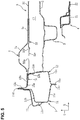
- the vehicle V comprises a pair of right-and-left side sills 1 , a floor panel 2 , a pair of right-and-left floor frame members 3 , called floor frames in the following, a battery unit 4 , first and second cross members 5 , 6 , and others. Further, the vehicle V comprises a pair of seat brackets 7 for supporting a pair of front seats which are provided at right-and-left both end portions of a first cross member 5.
- a direction shown by an arrow F means a forward (front) side, in a longitudinal direction, of the vehicle
- a direction shown by an arrow L means a leftward (left) side, in a width direction, of the vehicle
- a direction shown by an arrow U means an upward (upper) side, in a vertical direction, of the vehicle.
- the vehicle V is configured to be laterally symmetrical, and therefore the followings describe a right-side member or part of the vehicle primarily unless there are special explanations.
- the pair of side sills 1 will be described first.
- the right-side side sill 1 comprises an outer panel 11 which constitutes a right-side wall portion and an inner panel 12 which constitutes a left-side wall portion, and these panels 11 , 12 jointly form a nearly rectangular-shaped closed-cross section extending longitudinally.
- a hinge pillar 8 extending vertically is connected to a front-end-side portion of the side sill 1
- a rear pillar 9 extending vertically is connected to a rear-end-side portion of the side sill 1.
- this vehicle V is provided with a door structure of a so-called hinged double doors type in which a front door is opened/closed around a hinge provided at a front-end portion of the vehicle, a rear door is opened/closed around another hinge provided at a rear-end portion of the vehicle, and no center pillar is provided between the front door and the rear door.
- the outer panel 11 comprises an outward-side wall portion 11a which is provided to be perpendicular to the vehicle width direction, an upper wall portion 11b which extends in a leftward direction from an upper end portion of the outward-side wall portion 11a , a lower wall portion 11c which extends in the leftward direction from a lower end portion of the outward-side wall portion 11a , an upper flange portion 11d which extends upwardly from a leftward end portion of the upper wall portion 11b , and a lower flange portion 11e which extends downwardly from a leftward end portion of the lower end portion 11c.
- the outer panel 11 is configured to have a nearly hat-shaped cross section.
- an outer plate member 13 which is arranged on a rightward side of the outer panel 11 and an outer reinforcement 14 which is arranged on a leftward side of the outer panel 11.
- the outer plate member 13 is configured to cover the upper flange portion 11d , the upper wall portion 11b , and an upward-side portion of the outward-side wall portion 11a from a rightward side (outward side). Accordingly, the outer plate member 13 forms a closed-cross section extending from a front end of the outer panel 11 to a rear end of the outer panel 11 together with the outer panel 11.
- the outer reinforcement 14 is arranged on the rightward side, in the vehicle width direction, of a second cross member 6 in a plan view and have a nearly U-shaped lateral cross section.
- the outer reinforcement 14 is connected such that its upper end portion and its lower end portion are respectively connected to the upper flange portion 11d and the lower flange portion 11e , and a front end portion and a lower end portion of its middle-stage portion are connected to the outward-side wall portion 11a. Accordingly, each support rigidity of a front-door rear end portion and a rear-door front end portion is increased, so that the rigidity, in the vertical direction, of a vehicle-body middle part is secured in cooperation with the front door and the rear door.
- the inner panel 12 comprises an inward-side wall portion 12a which is provided to be perpendicular to the vehicle width direction, an upper wall portion 12b which extends in a rightward direction from an upper end portion of the inward-side wall portion 12a , a lower wall portion 12c which extends in the rightward direction from a lower end portion of the inward-side wall portion 12a , an upper flange portion 12d which extends upwardly from a rightward end portion of the upper wall portion 12b , and a lower flange portion 12e which extends downwardly from a rightward end portion of the lower end portion 12c.
- the inner panel 12 is configured to have a nearly hat-shaped cross section.
- the upper flange portion 12d and the lower flange portion 12e are respectively joined to the upper flange portion 11d and the lower flange portion 11e by spot welding.
- first inner reinforcement 15 (reinforcing member) which is arranged on the rightward side of the inner panel 12 and plural second inner reinforcements 16.
- the first inner reinforcement 15 is made of a ultrahigh tensile strength steel plate having the plate thickness of 2. 0mm, for example, and configured to have a nearly L-shaped cross section. As shown in FIGS. 4 through 8 , the first inner reinforcement 15 is provided to extend, in the lateral direction, from a left end (an inward end, in the vehicle width direction) of the inner panel 12 to a right end (an outward end, in the vehicle width direction) of the inner panel 12 , and extend, in the longitudinal direction, from a front end of the inner panel 12 to a rear end of the inner panel 12.
- This first inner reinforcement 15 comprises an upward-side reinforcement portion 15a which extends substantially horizontally and an inward-side reinforcement portion 15b which extends substantially vertically.
- the upward-side reinforcement portion 15a overlaps a roughly-whole area of the upper wall portion 12b in a close-contact state, and the inward-side reinforcement portion 15b partially overlaps an upward-side portion of the inward-side wall portion 12a in the close-contact state.
- the plural (e.g., four) second inner reinforcements 16 are respectively provided to be perpendicular to the longitudinal direction.
- the second inner reinforcements 16 are respectively joined to the inward-side wall portion 12a , the upper wall portion 12b , and the lower wall portion 12c , whereby at an inward side, in the vehicle width direction, of the closed-cross section of the side sill 1 are formed four gusset portions which partially close the closed-cross section of the side sill 1.
- the foremost second inner reinforcement 16 in the plan view is positioned such that it overlaps the hinge pillar 8 in the lateral direction, and the next second inner reinforcement 16 which is provided on a rearward side of the above-described foremost second inner reinforcement 16 is positioned slightly on a forward side of the first cross member 5.
- the other two second inner reinforcements 16 are positioned such that the second cross member 6 is interposed therebetween in the longitudinal direction, the forward-side one of which is positioned such that it overlaps the outer reinforcement 14 in the lateral direction.
- the floor panel 2 is provided to extend between the pair of side sills 1. Right-and-left both end portions of the floor panel 2 are respectively joined to the inward-side wall portions 12a of the pair of side sills 1 , whereby a floor surface of a cabin of the vehicle V is constituted. Otherwise, the construction of the floor panel and the pair of floor frames 3 is independent from the specifics of the construction of the side sills described above.
- a rear floor panel which forms a kick-up portion which extends obliquely rearwardly-and-upwardly is continuous from a rear end portion of the floor panel 2.
- the floor frames 3 are configured to have a nearly hat-shaped cross section, respectively, and such that a distance therebetween becomes larger as it goes to the rearward side. Accordingly, a distance between the side sill 1 and the floor frame 3 becomes smaller as it goes to the rearward side.
- the floor frame 3 forms a rectangular-shaped closed-cross section extending in the longitudinal direction together with a lower surface of the floor panel 2.
- the battery unit 4 As shown in FIGS. 3 and 4 , the battery unit 4 is arranged in a space below the floor panel 2 in a state where a high-voltage battery connecting plural battery modules in series is stored. Accordingly, the battery unit 4 is configured to have the vibration resistance and the water resistance.
- the battery modules to supply the electric power to the electric motor for driving the vehicle are a rectangular-parallelepiped-shaped battery assembly where plural rectangular-parallelepiped-shaped battery cells to generate a standard voltage are arranged in a laminated state.
- the battery cell is a lithium ion battery which is a kind of secondary battery, for example.
- the battery unit 4 primarily comprises a battery frame 21 , a bottom plate 22 , an upper cover 23 , and plural support members 24.
- the battery frame 21 is configured to have a nearly square-shaped closed-cross-section structural body which is formed by a crank-shaped upper frame and a crank-shaped lower frame (see FIGS. 5 and 6 ).
- the bottom plate 22 is made of metal excellent in thermal conductivity, such as aluminum alloy. An edge portion of the bottom plate 22 is supported at an upper wall portion and a flange portion of the battery frame 21.
- the battery frame 21 and the bottom plate 22 correspond to a lower cover of the battery unit 4.
- the upper cover 23 is fixed to an inner edge of the upper wall portion of the battery frame 21 via a seal gasket (not illustrated) in the close-contact state.
- the four support members 24 protrude outwardly, in the vehicle width direction, from left-and-right side portions of the battery frame 21. These support members 24 are fixedly fastened to respective lower wall portions of the pair of floor frames 3 by means of fastening members.
- the battery unit 4 is arranged below the floor panel 2 and between the pair of floor frames 3.
- the first cross member 5 interconnects respective front-side parts of the pair of side sills 1 and forms a rectangular-shaped first closed-cross section C1 extending laterally together with the upper surface of the floor panel 2 .
- the first cross member 5 comprises a first middle portion 31 and a pair of right-and-left first side portions 32 which extend outwardly, in the vehicle width direction, from right-and-left both end portions of the first middle portion 31.
- the first middle portion 31 is made of a ultrahigh tensile strength steel plate having the plate thickness of 1. 8mm, for example, and configured to have a nearly hat-shaped cross section.
- a flange portion formed at a lower end portion of the first middle portion 31 is joined to the upper surface of the floor panel 2 by welding.
- the pair of first side portions 32 are respectively made of a steel plate having lower toughness and rigidity than the first middle portion 31 , such as a cold rolled steel plate having the plate thickness of 1. 0mm, for example, and configured to have a nearly hat-shaped cross section.
- the right-side first side portion 32 comprises a front wall portion 32a which is provided to be perpendicular to the longitudinal direction, a rear wall portion 32b which faces the front wall portion 32a with a specified distance therebetween, an upper wall portion 32c which connects respective upper end portions of the front wall portion 32a and the rear wall portion 32b , and so on.
- Flange portions formed at respective lower end portions of the front wall portion 32a and the rear wall portion 32b are joined to the upper surface of the floor panel 2 by welding, and a flange portion formed at the right side (the outward side, in the vehicle width direction) thereof is joined to the inward-side wall portion 12a.
- the upper wall portion 32c is joined such that an upper face of a left-side (inward-side, in the vehicle width direction) end portion thereof is welded to a lower face of a right-side end portion of the upper wall portion of the first middle portion 31 and a lower face of a right-side (outward-side, in the vehicle width direction) end portion thereof is welded to an upper face of the upper wall portion 12b of the inner panel 12.
- the construction of the floor panel and the pair of floor frames 3 is independent from the specifics of the construction of the side sills described above.
- the upper wall portion 32c is provided with bead portions 32s , 32t which are respectively configured to be recessed (concaved) downwardly and extend in the longitudinal direction and an opening portion 32u which is configured to penetrate the upper wall portion 32c vertically.
- the bead portion 32s is formed on the right side (the outward side, in the vehicle width direction) of the floor frame 3, and the bead portion 32t is formed on the right side of the bead portion 32s.
- the opening portion 32u is of a nearly oval shape and configured to overlap the bead portion 32t in the vehicle width direction.
- the second cross member 6 interconnects respective middle parts of the pair of side sills 1 in back of the first cross member 5 and forms a rectangular-shaped second closed-cross section C2 extending laterally together with the upper surface of the floor panel 2.
- the second closed-cross section C2 is set to have a smaller sectional area than the first closed-cross section C1 .
- a secondary cross-sectional moment of the second cross member 6 is set to be smaller than that of the first cross member 5.
- the second cross member 6 comprises a second middle portion 41 and a pair of right-and-left second side portions 42 which extend outwardly, in the vehicle width direction, from right-and-left both end portions of the second middle portion 41.
- the second middle portion 41 is made of a ultrahigh tensile strength steel plate having the plate thickness of 2. 3mm, for example, and configured to have a nearly hat-shaped cross section.
- a flange portion formed at a lower end portion of the second middle portion 41 is joined to the upper surface of the floor panel 2 by welding.
- the pair of second side portions 42 are respectively made of a steel plate having lower toughness and rigidity than the second middle portion 41 , such as a cold rolled steel plate having the plate thickness of 2. 3mm, for example, and configured to have a nearly hat-shaped cross section.
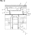
- the right-side second side portion 42 comprises a front wall portion 42a which is provided to be perpendicular to the longitudinal direction, a rear wall portion 42b which faces the front wall portion 42b with a specified distance therebetween, an upper wall portion 42c which connect respective upper end portions of the front wall portion 42a and the rear wall portion 42b , and so on.
- the second side portion 42 is provided with a step portion 42q where the level (height position) of a right-side portion thereof is higher than that of a left-side portion thereof.
- the step portion 42q is a portion which extends between the inner panel 12 and the floor frame 3.
- the present embodiment is configured such that the distance between the inward-side wall portion 12a of the inner panel 12 and the step portion 42q is nearly equal to the distance between the inward-side wall portion 12a of the inner panel 12 and the bead portion 32s .
- a linear-shaped ridgeline portion 42r which protrudes in an opposite direction to the second closed-cross section C2 is formed at each of the front wall portion 42a and the rear wall portion 42b.
- the ridgeline portion 42r is configured such that its upper end portion is located at a position corresponding to the step portion 42q and it extends obliquely downwardly-and-outwardly.
- Flange portions formed at respective lower end portions of the front wall portion 42a and the rear wall portion 42b are joined to the upper surface of the floor panel 2 by welding, and a flange portion formed at the right side (the outward side, in the vehicle width direction) thereof is joined to the inward-side wall portion 12a.
- the upper wall portion 42c is joined such that an upper face of a left-side (inward-side, in the vehicle width direction) end portion thereof is welded to a lower face of a right-side end portion of the upper wall portion of the second middle portion 41 and a lower face of a right-side (outward-side, in the vehicle width direction) end portion thereof is welded to an upper face of the upper wall portion 12b of the inner panel 12.
- the upper wall portion 42c is provided with a bead portion 42s which is configured to be recessed (concaved) downwardly and extend longitudinally.
- the bead portion 42s is formed at a position located on the left side (the inward side, in the vehicle width direction) of the step portion 42q and between the right-and-left vertical wall portion of the floor frame 3.
- a foot space of a passenger seated in the rear seat is secured and deterioration of the energy absorption performance in a case of the vehicle side collision is suppressed. Further, deterioration of the energy absorption performance in the case of the vehicle side collision, which may be caused by the sectional area of the second cross member 6 being smaller than the sectional area of the first cross member 5 , is suppressed by collapsing of the floor frame 3 in addition to collapsing of the first and second side portions 32, 43.
- each of the pair of floor frames 3 extends obliquely such that its rearward side is located on the right side (on the outward side, in the vehicle width direction) of its forward side, a position of an inward end of the first side portion 32 of the first cross member 5 is located at the same position, in the vehicle width direction, as the floor frame 3 , and a position of an inward end of the second side portion 42 of the second cross member 6 is located on the leftward side (on the inward side, in the vehicle width direction) of the floor frame 3.
- a side door (not illustrated) can be properly suppressed from coming into the cabin in the vehicle side collision by the stopper bracket 51 and also deterioration of the energy absorption performance of the side sill 1 which may be caused by providing the stopper bracket 51 can be properly suppressed by both collapsing of the first and second side portions 32 , 42 and the floor frame 3.
- the pair of seat brackets 7 will be described. These are provided as the seat bracket 7 to support a front portion of an outward side, in the vehicle width direction, of a driver's seat seating a driver and the seat bracket 7 to support an front portion of an outward side, in the vehicle width direction, of a driver's assistant seat seating a passenger.
- a seat bracket to support a front portion of each inward side, in the vehicle width direction, of the driver's seat and the driver's assistant seat is provided around a middle portion, in the lateral direction, of the first cross member 5.
- the right-side seat bracket 7 is provided to cover an upper half part of the right-side first side portion 32.
- the seat bracket 7 is made of the cold rolled steel plate having the plate thickness of 2. 3mm, for example, and configured to have a nearly U-shaped cross section.
- the seat bracket 7 comprises a front wall portion 7a which is provided to be perpendicular to the longitudinal direction, a rear wall portion 7b which faces the front wall portion 7a with a specified distance therebetween, an upper wall portion 7c which connects respective upper end portions of the front wall portion 7a and the rear wall portion 7b , and so on.
- the seat bracket 7 is provided with a protrusion portion 7e which is upwardly spaced apart from the upper wall portion 32c of the first cross member 5 (the first side portion 32 ).
- the protrusion portion 7e is a portion which extends between the inner panel 12 and the floor frame 3 and configured to be of a trapezoidal shape in an elevational view.
- the upper wall portion of the first middle portion 31 and the upper wall portion 32c of the pair of first side portions 32 correspond to the upper face portion of the first cross member 5
- a part of the upper wall portion 32c of the first side portions 32 which is covered with the protrusion portion 7e of the seat bracket 7 corresponds to a part of the upper face portion of the first cross member 5 in the claims.
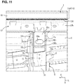
- a bead portion 7s which protrudes in an opposite direction to the protrusion portion 7e and extends vertically is formed at each of the front wall portion 7a and the rear wall portion 7b. As shown in FIGS. 7 , 9 and 11 , the bead portion 7s is arranged on the right side of the bead portion 32t and configured such that its lateral width becomes larger as it goes downwardly from the upper end portion of the front wall portion 7a. Flange portions formed at lower end portions of the front wall portion 7a and the rear wall portion 7b are welded to the front wall portion 32a and the rear wall portion 32b of the first cross member 5 (the first side portion 32 ), respectively, such that the bead portion 7s is laterally interposed therebetween.
- the upper wall portion 7c is configured such that its left-side end portion extends to the inner panel 12 (the inward-side wall portion 12a ) and a lower face of its right-side end portion is joined to an upper face of a right-side end portion of the upper wall portion of the first middle portion 31 by welding.
- the right-side end portion of the upper wall potion of the first middle portion 31 is interposed between the upper wall portion 32c of the first side wall 32 and the upper wall portion 7c , and these three members are joined by welding.
- a collision load is inputted to a part, in a longitudinal direction, of the side sill 1. Since the reinforcements 14 - 16 are provided inside the side sill 1 , sectional collapsing of the side sill 1 is suppressed. In particular, since the first inner reinforcement 15 is formed over a whole length of the side sill 1 , even if the input load is inputted to a specified point of the outer panel 11 , the input load is dispersed to a whole part of the first inner reinforcement 15 through a load path which is composed of the plural framework members, such as the first and second cross members 5 , 6.
- the input load causes inwardly-generated collapse deformation of the side sill 1 as well as upwardly-rotational move of the side sill 1 around its joint portion to the floor panel 2.
- the input load causes bending deformation of the front wall portion 7a and the rear wall portion 7b with its deformation starting point located at the bead portion 7s of the seat bracket 7 , and then causes collapse deformation of the first side portion 32 with its deformation starting point located at the bead portions 32s , 32t and the opening portion 32u which are formed at the upper wall portion 32c. Since the first side portion 32 is configured to have lower toughness than the first middle portion 31 , the sufficient collapse deformation is achieved even if the seat bracket 7 is provided.
- the input load causes bending deformation of the front wall portion 42a and the rear wall portion 42b with its deformation starting point located at the ridgeline portion 42r and collapse deformation of the second side portion 42 with its deformation starting point located at the bead portion 42s.
- the sectional area of the second closed-cross section C2 of the second cross member 6 is set to be smaller than that of the first closed-cross section C1 of the first cross member 5 , so that respective collapse-deformation tendencies of the collapse deformation of the first and second cross members 5 , 6 relative to the floor frame 3 are matched.
- the remaining collision load which has not be absorbed by the collapse deformation of the first side portion 32 and others causes inwardly-generated deformation of the floor frame 3.
- a part of the load inputted at the initial stage is absorbed by the collapse deformation of the first and second side portions 32 , 42 and the bending deformation of the seat bracket 7 , and also another part of the input load is dispersed to the other framework members (e.g., the opposite-side side sill 1 , hinge pillar 8 , rear pillar 9 , and so on) through the first and second cross members 5 , 6 , so that the deformation of the floor frame 3 is suppressed. Thereby, the damage of the battery unit 4 can be minimized.
- the seat bracket 7 comprises the protrusion portion 7e which partially covers the upper wall portion 32c of the first side portion 32 (the first cross member 5 ) and is upwardly spaced apart from the upper wall portion 32c of the first cross member 5
- the first cross member 5 is provided with the part of the upper face portion thereof (i.e., the part of the upper wall portion 32c of the first side portion 32 ) which is spaced apart from the seat bracket 7 and also the seat bracket 7 can be disposed at the first cross member 5.
- the low-rigidity portion is formed at the part of the upper face portion of the first cross member 5 (i.e., the part of the upper wall portion 32c of the first side portion 32 ) which is located at the position corresponding to the protrusion portion 7e of the seat bracket 7 and this low-rigidity portion is configured to make rigidity of the part of the upper face portion of the first cross member 5 (i.e., the part of the upper wall portion 32c of the first side portion 32 ) where the low-rigidity portion is formed be lower than that of the other part of the upper face portion of the cross member 5 where the low-rigidity portion is not formed, the above-described part of the upper face portion of the first cross member 5 (i.e., the part of the upper wall portion 32c of the first side portion 32 ) can be properly collapsed and deformed inwardly, in the vehicle width direction, by the load inputted in the vehicle side collision, without improperly decreasing the rigidity of the front wall portion 32a and the rear wall portion 32b of the
- the low-rigidity portion is the bead portions 32s , 32t which are configured to extend in the vehicle longitudinal direction at the above-described part of the upper face portion of the first cross member 5 (i.e., the part of the upper wall portion 32c of the first side portion 32 ), the above-described part of the upper face portion of the first cross member 5 (i.e., the part of the upper wall portion 32c of the first side portion 32 ) can be properly collapsed and deformed inwardly, in the vehicle width direction, with a simple structure.
- the low-rigidity portion is the opening portion 32u which is formed at the part of the upper face portion of the first cross member 5 (i.e., the part of the upper wall portion 32c of the first side portion 32 )
- the above-described part of the upper face portion of the first cross member 5 i.e., the part of the upper wall portion 32c of the first side portion 32
- the above-described part of the upper face portion of the first cross member 5 i.e., the part of the upper wall portion 32c of the first side portion 32
- the low-rigidity portion is composed by the opening portion 32u and the bead portion 32t which are formed at the part of the upper face portion of the first cross member 5 (i.e., the part of the upper wall portion 32c of the first side portion 32 ) such that the bead portion 32t extends in the vehicle longitudinal direction, overlapping the opening portion 32u in the vehicle width direction, the energy absorption (EA) performance in the case of the vehicle side collision can be further improved.
- EA energy absorption
- the seat bracket 7 further comprises the front wall portion 7a , the rear wall portion 7b which faces the front wall portion 7a , and the upper wall portion 7c which connects the respective upper ends of the front wall portion 7a and the rear wall portion 7b , and the bead portion 7s which extends in the vertical direction is formed at each of the front wall portion 7a and the rear wall portion 7b.
- the seat bracket 7 can be bent and deformed inwardly in the vehicle width direction, without reducing the rigidity, in the vertical direction, of the front wall portion 7a and the rear wall portion 7b of the seat bracket 7 , and the first cross member 1 can be allowed to have inwardly-generated collapse deformation which is caused by the load inputted in the vehicle side collision.
- the opening portion 32u is formed at a portion of the upper face portion of the first cross member 5 which is enclosed by the bead portions 7s formed at the front wall portion 7a and the rear wall portion 7b , the bending deformation of the seat bracket 7 which is caused by the bead portions 7s and the collapse deformation of the first cross member 5 which is caused by the opening portion 32u can be synchronized, so that the collapse deformation of the first cross member 1 can be promoted.
- each of the front wall portion 7a and the rear wall portion 7b of the seat bracket 7 is joined to the first cross member 1 at portions which interpose the bead portion 7s between the portions, the seat bracket 7 can be joined to the first cross member 1 , without hindering the bending deformation of the seat bracket 7.
- the lower vehicle-body structure further comprises the second cross member 6 interconnecting the pair of side sills 1 at the foot space of the passenger seated in the rear seat which is positioned on the rearward side, in the vehicle longitudinal direction, of the first cross member 5 , the first cross member 5 forms the first closed-cross section C1 extending in the vehicle width direction together with the floor panel 3 , the second cross member 6 forms the second closed-cross section C2 extending in the vehicle width direction together with the floor panel 3 , the second closed-cross section C2 is set to have a lower sectional height and the smaller sectional area than the first closed-cross section C1 , and the position of the inward end of the second side portion 42 of the second cross member 6 is located on the inward side, in the vehicle width direction, of the position of the inward end of the first side portion 32 of the first cross member 5.
- the foot space of the passenger seated in the rear seat can be secured properly by lowering the sectional height of the second cross member 6 and also deterioration of the energy absorption performance in the case of the vehicle side collision can be suppressed by decreasing the sectional area of the second cross member 6 and thereby positioning the inward end of the second side portion 42 at the inward side in the vehicle width direction.
- each of the pair of floor frames 3 extends obliquely such that its rearward side is located on the outward side, in the vehicle width direction, of its forward side, the position of the inward end of the first side portion 32 of the first cross member 5 is located at the same position, in the vehicle width direction, as the floor frame 3 , and the position of the inward end of the second side portion 42 of the second cross member 6 is located on the inward side, in the vehicle width direction, of the floor frame 3 , the deterioration of the energy absorption performance in the case of the vehicle side collision which may be caused by setting the second cross member 6 to have the smaller sectional area than the first cross member 5 can be properly suppressed by collapsing of the floor frame 3 in addition to collapsing of the first and second side portions 32 , 42 .
- the rigidity, in the vehicle width direction, of the side sill 1 can be effectively increased by the reinforcing member 15. Further, since the reinforcing member 15 is provided to extend at least from the first cross member 5 to the second cross member 6 , the load path reaching the first and second cross members 5 , 6 can be created via the reinforcing member 15 regardless of the input position of the collision load in the vehicle side collision, so that the load applied in the vehicle side collision can be dispersed by utilizing the framework structure of the vehicle body.
- Each of the first and second cross members 5 , 6 is configured such that its outward-side portion which is positioned on the outward side, in the vehicle width direction, of the floor frame 3 has the lower rigidity than its inward-side portion which is positioned on the inward side, in the vehicle width direction, of the floor frame 3. Accordingly, the respective outward-side portions of the first and second cross members 5 , 6 which are positioned on the outward side, in the vehicle width direction, of the floor frame 3 can be made to have the inwardly-generated collapse deformation, so that the energy absorption performance in the case of the vehicle side collision can be improved.
- each of the pair of side sills 1 comprises the side sill outer 11 which forms the outward-side portion, in the vehicle width direction, thereof and the side sill inner 12 which forms the inward-side portion, in the vehicle width direction, thereof, and the first reinforcing member 15 is provided to extend from the inward end, in the vehicle width direction, of the side sill inner 12 to the outward end, in the vehicle width direction, of the side sill inner 12 , the load applied in the vehicle side collision can be dispersed, preventing buckling of the side sill 1.
- the side sill inner 12 comprises the upper wall portion 12b , the lower wall portion 12c which faces the upper wall portion 12b , and the inward-side wall portion 12a which connects the respective inward-side ends, in the vehicle width direction, of the upper wall portion 12b and the lower wall portion 12c , and the first reinforcing member 15 is provided to extend from the upper wall portion 12b to the inward-side wall portion 12a , the load applied in the vehicle side collision can be dispersed, preventing sectional collapsing of the side sill 1.
- the first reinforcing member 15 is provided to extend from the front end of the side sill inner 12 to the rear end of the side sill inner 12, the load path reaching the first and second cross members 5, 6 can be created even when the input position of the collision load is far away from the first and second cross members 5, 6.
- the lower vehicle-body structure further comprises the stopper bracket 51 which is provided to connect the upper wall portion 12b of side sill inner 12 and the upper flange portion 12d of the side sill inner 12 so as to suppress the side door of the vehicle from coming into the cabin in the vehicle side collision, wherein each of the pair of floor frames 3 extends obliquely such that its rearward side is located on the outward side, in the vehicle width direction, of its forward side, the position of the inward end of the first side portion 32 of the first cross member 5 is located at the same position, in the vehicle width direction, as the floor frame 3, and the position of the inward end of the second side portion 42 of the second cross member 6 is located on the inward side, in the vehicle width direction, of the floor frame 3.
- the side door can be properly suppressed from coming into the cabin in the vehicle side collision by the stopper bracket 51 and also deterioration of the energy absorption performance of the side sill 1 which may be caused by providing the stopper bracket 51 can be properly suppressed by both collapsing of the first and second side portions 32, 42 and the floor frame 3.
Abstract
Description
- The present invention relates to a lower vehicle-body structure of a vehicle, and in particular, relates to the lower vehicle-body structure of the vehicle which comprises a battery unit provided between a pair of floor frames and a seat bracket provided at an outward-side end portion, in a vehicle width direction, of a cross member which interconnects a pair of side sills in a vehicle width direction.
- Conventionally, in an electric vehicle, such as a hybrid vehicle or an electric automotive vehicle, a battery unit is provided by using a space below a vehicle-body floor because a battery as a power source of an electric motor to drive vehicle wheels (e.g., a motor generator or a motor) has a large (high) capacity. In general, the battery unit comprises a plurality of battery modules which are composed of a battery-cell assembly, such as lithium-ion battery cells, an upper cover and a lower cover which store (accommodate) these plural battery modules, a support member which supports these covers at a vehicle body, and so on.
- A floor structure of an automotive vehicle disclosed in
WO2012/063393 (US Patent Application Publication No. 2013/0229030 A1 ) comprises a pair of right-and-left side sills extending in a vehicle longitudinal direction, a floor panel provided to extend between the pair of side sills, a pair of right-and-left floor frames extending in the vehicle longitudinal direction between the pair of side sills on a downward side of the floor panel, a battery unit provided between the pair of floor frames, an upper cross member interconnecting the pair of side sills on an upward side of the floor panel, and a lower cross member interconnecting the pair of side sills on a downward side of the floor panel at a position located below the upper cross member, wherein the battery unit is interposed between the upper cross member and the lower cross member. Herein, the upper cross member is configured such that a part thereof which extends between the side sill and the floor frame has a thinner plate thickness than another part thereof which extends on an inward side, in the vehicle width direction, of the floor frame in order to suppress deformation of the floor frames in a vehicle side collision. - Further, the technologies to improve the energy absorption (EA) performance of the cross member in a case of the vehicle side collision structurally, not by a material itself, such as the plate thickness or the quality of a material, have been proposed. A vehicle-body floor structure disclosed in Japanese Patent Laid-Open Publication No.
H7-81625 - The cross member interconnecting the pair of side sills forms a closed-cross section extending in the vehicle width direction together with an upper surface of the floor panel, which is one of major rigidity members which constitute a framework (skeleton) of the vehicle body. Therefore, seat brackets to support a seat capable of seating a passenger are provided at an outward-side (side-sill side) end portion, in the vehicle width direction, of the cross member which is a rigidity member and an inward-side (tunnel side) end portion, in the vehicle width direction, of the cross member.
- The seat bracket is required to have the passenger-supporting rigidity which is so high in the vertical direction that an appropriate driving position can be secured regardless of a vehicle-traveling condition. That is, even if the structure in which a low-rigidity portion, the bead portions or the like are provided at the cross member is adopted as shown in the above-described patent documents, in a case where the high-rigidity seat bracket is provided at a part of the cross member which is interposed between the side sill and the floor frame, an increase of the rigidity of the part of the cross member provided with the seat bracket may improperly hinder the smooth collapse deformation of the cross member, so that there is a concern that the expected EA (energy absorption) performance may not be secured.
- Herein, Japanese Patent Laid-Open Publication No.
2016-153269 - Accordingly, an object of the present invention is to provide a low vehicle-body structure of a vehicle which can compatibly secure the support rigidity of the seat bracket and the energy absorption (EA) performance of the cross member.
- This object is solved by the lower vehicle-body structure of the vehicle according to the present invention of the independent claim. Preferred embodiments of the present invention are subject of the other dependent claims.
- The present invention is a lower vehicle-body structure of a vehicle, comprising a pair of side sills extending in a vehicle longitudinal direction, a floor panel provided to extend between the pair of side sills, a pair of floor frames extending in the vehicle longitudinal direction between the pair of side sills on a downward side of the floor panel, a battery unit provided between the pair of floor frames, a first cross member interconnecting the pair of side sills on an upward side of the floor panel, and a seat bracket supporting a seat capable of seating a passenger and provided on the first cross member, wherein the seat bracket comprises a protrusion portion which partially covers an upper face portion of the first cross member and is upwardly spaced apart from the upper face portion of the first cross member, and a deformation portion is formed at a part of the upper face portion of the first cross member which is located at a position corresponding to and/or covered by the protrusion portion of the seat bracket.
- Preferably, the deformation portion is a low-rigidity portion configured to make rigidity of the part of the upper face portion of the first cross member where the deformation portion is formed be lower than that of the other part of the upper face of the cross member where the deformation portion is not formed.
- Preferably, the seat bracket is provided at an outward end portion, in a vehicle width direction, of the first cross member.
- The floor frames may in particular be floor frame members.
- According to the present invention, since the seat bracket comprises the protrusion portion which partially covers the upper face portion of the first cross member and is upwardly spaced apart from the upper face portion of the first cross member, the first cross member is provided with the part of the upper face portion thereof which is spaced apart from the seat bracket and also the seat bracket can be disposed at the first cross member. Further, since the deformation portion is formed at the part of the upper face portion of the first cross member which is located at the position corresponding to the protrusion portion of the seat bracket and this deformation portion is configured to make rigidity of the part of the upper face portion of the first cross member where the deformation portion is formed be lower than that of the other part of the upper face of the cross member where the deformation portion is not formed, the above-described part of the upper face portion of the first cross member can be properly collapsed and deformed inwardly, in the vehicle width direction, by a load inputted in the vehicle side collision, without improperly decreasing the rigidity of a vertical wall portion (the front wall portion and the rear wall portion) of the first cross member which contributes to the support rigidity of the seat bracket.
- In an embodiment of the present invention, the deformation portion comprises or is formed by one or plural bead portions which are configured to extend in the vehicle longitudinal direction at the part of the upper face portion of the first cross member.
- According to this embodiment, the above-described part of the upper face portion of the first cross member can be properly collapsed and deformed inwardly, in the vehicle width direction, with a simple structure.
- In another embodiment of the present invention, the deformation portion comprises or is formed by an opening portion which is formed at the part of the upper face portion of the first cross member.
- According to this embodiment, the above-described part of the upper face portion of the first cross member can be properly collapsed and deformed inwardly, in the vehicle width direction, achieving weight reduction.
- In another embodiment of the present invention, the deformation portion comprises or is formed by an opening portion and a bead portion which are formed at the part of the upper face portion of the first cross member such that the bead portion extends in the vehicle longitudinal direction, overlapping the opening portion in the vehicle width direction.
- According to this embodiment, the energy absorption (EA) performance in the case of the vehicle side collision can be further improved.
- In another embodiment of the present invention, the seat bracket further comprises a front wall portion, a rear wall portion which faces the front wall portion, and an upper wall portion which connects respective upper ends of the front wall portion and the rear wall portion, and a bead portion which extends in a vertical direction is formed at each of the front wall portion and the rear wall portion.
- According to this embodiment, the seat bracket can be bent and deformed inwardly in the vehicle width direction, without reducing the rigidity, in the vertical direction, of the front wall portion and the rear wall portion of the seat bracket, and the first cross member can be allowed to have inwardly-generated collapse deformation which is caused by the load inputted in the vehicle side collision.
- In another embodiment of the present invention, an opening portion is formed at a portion of the upper face portion of the first cross member which is enclosed by the bead portions formed at the front wall portion and the rear wall portion.
- According to this embodiment, the bending deformation of the seat bracket which is caused by the bead portion and the collapse deformation of the first cross member which is caused by the opening portion can be synchronized, so that the collapse deformation of the first cross member can be promoted.
- In another embodiment of the present invention, each of the front wall portion and the rear wall portion of the seat bracket is joined to the first cross member at portions thereof which interpose the bead portion between the portions.
- According to this embodiment, the seat bracket can be joined to the first cross member, without hindering the bending deformation of the seat bracket.
- In another embodiment of the present invention, the lower vehicle-body structure further comprises a second cross member interconnecting the pair of side sills at a foot space of a passenger seated in a rear seat which is positioned on a rearward side, in the vehicle longitudinal direction, of the first cross member.
- Preferably, the first cross member forms a first closed-cross section extending in a vehicle width direction together with the floor panel, the second cross member forms a second closed-cross section extending in the vehicle width direction together with the floor panel, the second closed-cross section is set to have a lower sectional height and/or a smaller sectional area than the first closed-cross section. In particular, the second closed-cross section may have a lower sectional height and/or a smaller sectional area than the first closed-cross section at at least one position in the vehicle width direction. Preferably, the second closed-cross section may have a lower sectional height and/or a smaller sectional area than the first closed-cross section when averaged over the vehicle width direction and/or along at least 70% of their extension in the vehicle width direction, preferably over at least 80% and 90% of their extension in the vehicle width direction.
- Preferably, a position of an inward end of a low-rigidity portion which is formed at the second cross member is located on an inward side, in the vehicle width direction, of a position of an inward end of a low-rigidity portion which is formed at the first cross member. In an embodiment, the low-rigidity portion is a side portion of the first cross member formed from a different material and/or a plate having a different thickness, in particular from a steel plate having a lower rigidity and/or lower thickness, than a middle portion of the first cross member.
- According to this embodiment, the foot space of the passenger seated in the rear seat can be secured properly by lowering the sectional height of the second cross member and also deterioration of the energy absorption performance in the case of the vehicle side collision can be suppressed by decreasing the sectional area of the second cross member and positioning the inward end of the low-rigidity portion at the inward side in the vehicle width direction.
- In another embodiment of the present invention, each of the pair of floor frames extends obliquely such that a rearward side thereof is located on an outward side, in the vehicle width direction, of a forward side thereof, the position of the inward end of the low-rigidity portion formed at the first cross member is located at a position overlapping with the position, in the vehicle width direction, of the floor frame, and the position of the inward end of the low-rigidity portion formed at the second cross member is located on the inward side, in the vehicle width direction, of the floor frame. In particular, the inward end of the low-rigidity portion formed at the first cross member may be located at the same position, in the vehicle width direction, as the floor frame and in particular at the same position as an inner side wall of the floor frame.
- According to this embodiment, the deterioration of the energy absorption performance in the case of the vehicle side collision which may be caused by setting the second cross member to have the smaller sectional area than the first cross member can be properly suppressed by collapsing of the floor frame in addition to collapsing of the low-rigidity portion.
- In an embodiment of the present invention, the second cross member comprises a deformation portion formed at a part of its upper wall portion. In particular, the deformation portion may be formed at an outward end portion, in a vehicle width direction, of the second cross member.
- In an embodiment, the deformation portion may comprise a step portion where an outer side portion is higher than an inner side portion of the step portion.
- In an embodiment, the step portion may extend between the sill and a position of the frame member in a vehicle width direction.
- In an embodiment, the second cross member may comprise ridgeline portions in a front wall and a back wall connected by the upper wall portion, the ridgeline portions extending obliquely downward and outward from the step portion.
- In an embodiment, the deformation portion may comprise a bead portion extending in the vehicle longitudinal direction.
- In another embodiment of the present invention, the lower vehicle-body structure further comprises a second cross member interconnecting the pair of side sills at a position which is located on an upward side of the battery unit via the floor panel and on a rearward side of the first cross member, wherein a reinforcing member which extends substantially horizontally is provided inside each of the pair of side sills, and the reinforcing member is provided to extend at least from the first cross member to the second cross member.
- According to this embodiment, since the reinforcing member extending substantially horizontally is provided inside each of the pair of side sills, the rigidity, in the vehicle width direction, of the side sill can be effectively increased by the reinforcing member. Further, since the reinforcing member is provided to extend at least from the first cross member to the second cross member, a load path reaching the first and second cross members can be created via the reinforcing member regardless of an input position of a collision load in the vehicle side collision, so that the load applied in the vehicle side collision can be dispersed by utilizing the framework structure of the vehicle body.
- In another embodiment of the present invention, each of the first and second cross members is configured such that an outward-side portion thereof which is positioned on an outward side, in the vehicle width direction, of the floor frame has lower rigidity than an inward-side portion thereof which is positioned on an inward side, in the vehicle width direction, of the floor frame. In an embodiment, the outward-side portions are formed from a different material and/or a plate having a different thickness, in particular are formed from a steel plate having a lower rigidity and/or lower thickness, than at least a part of the inward side portions and in particular a middle portion of the respective cross member.
- According to this embodiment, the respective outward-side portions of the first and second cross members which are positioned on the outward side, in the vehicle width direction, of the floor frame can be made to have the inwardly-generated collapse deformation, so that the energy absorption performance in the case of the vehicle side collision can be improved.
- In another embodiment of the present invention, each of the pair of side sills comprises a side sill outer wall member which forms an outward-side portion, in the vehicle width direction, thereof and a side sill inner wall member which forms an inward-side portion, in the vehicle width direction, thereof, and the reinforcing member is provided to extend from an inward end, in the vehicle width direction, of the side sill inner wall member to an outward end, in the vehicle width direction, of the side sill inner wall member .
- According to this embodiment, the load applied in the vehicle side collision can be dispersed, preventing buckling of the side sill.
- In another embodiment of the present invention, the side sill inner wall member comprises an upper wall portion, a lower wall portion which faces the upper wall portion, and an inward-side wall portion which connects respective inward-side ends, in the vehicle width direction, of the upper wall portion and the lower wall portion, and the reinforcing member is provided to extend from the upper wall portion to the inward-side wall portion.
- According to this embodiment, the load applied in the vehicle side collision can be dispersed, preventing sectional collapsing of the side sill.
- In another embodiment of the present invention, the reinforcing member is provided to extend from a front end of the side sill inner wall member to a rear end of the side sill inner.
- According to this embodiment, the load path reaching the first and second cross members can be created even when the input position of the collision load is far away from the first and second cross members.
- In another embodiment of the present invention, the lower vehicle-body structure further comprises a stopper bracket which is provided to connect an upper wall portion of side sill inner wall member and a flange portion of the side sill inner wall member so as to suppress a side door of the vehicle from coming into a cabin in a vehicle side collision.
- Preferably, each of the pair of floor frames extends obliquely such that a rearward side thereof is located on the outward side, in the vehicle width direction, of a forward side thereof, a position of an inward end of a low-rigidity portion which is formed at the first cross member is located at a position, in the vehicle width direction, overlapping with the floor frame, and a position of an inward end of a low-rigidity portion which is formed at the second cross member is located on the inward side, in the vehicle width direction, of the floor frame. In particular, the inward end of the low-rigidity portion formed at the first cross member may be located at the same position, in the vehicle width direction, as the floor frame and in particular at the same position as an inner side wall of the floor frame.
- According to this embodiment, the side door can be properly suppressed from coming into the cabin in the vehicle side collision by the stopper bracket and also deterioration of the energy absorption performance of the side sill which may be caused by providing the stopper bracket can be properly suppressed by both collapsing of the low-rigidity portion and the floor frame.
- The present invention will become apparent from the following description which refers to the accompanying drawings.
-
FIG. 1 is a perspective view of an upper part of a lower vehicle body of a vehicle according to an embodiment of the present invention. -
FIG. 2 is a plan view. -
FIG. 3 is a back view. -
FIG. 4 is a partially-exploded perspective view. -
FIG. 5 is a sectional view taken along line V-V ofFIG. 2 . -
FIG. 6 is a sectional view taken along line VI-VI ofFIG. 2 . -
FIG. 7 is a sectional view taken along line VII-VII ofFIG. 2 . -
FIG. 8 is a sectional view taken along line VIII-VIII ofFIG. 2 . -
FIG. 9 is an enlarged view of a major part ofFIG. 1 . -
FIG. 10 is a perspective view in a state where illustration of a seat bracket is omitted fromFIG. 5 . -
FIG. 11 is a sectional view taken along line XI-XI ofFIG. 7 . -
FIG. 12 is a sectional view taken along line XII-XII ofFIG. 8 . -
FIG. 13 is a sectional view taken along line XIII-XIII ofFIG. 7 . - Hereafter, an embodiment of the present invention will be described referring to the drawings. The following description regarding the embodiment relates to merely an exemplified invention and should not limit the present invention and its application or use.
- The present embodiment will be specifically described referring to
FIGS. 1 through 13 . A vehicle V according to the present embodiment may in particular be a hybrid automotive vehicle which combines an internal combustion engine (not illustrated), such as a gasoline or diesel engine, and an electric motor (motor generator) for driving the vehicle as a drive (power) source, or an electric vehicle. - As shown in
FIGS. 1 through 4 , the vehicle V comprises a pair of right-and-left side sills 1, afloor panel 2, a pair of right-and-leftfloor frame members 3, called floor frames in the following, abattery unit 4, first andsecond cross members seat brackets 7 for supporting a pair of front seats which are provided at right-and-left both end portions of afirst cross member 5. In the figures, a direction shown by an arrow F means a forward (front) side, in a longitudinal direction, of the vehicle, a direction shown by an arrow L means a leftward (left) side, in a width direction, of the vehicle, and a direction shown by an arrow U means an upward (upper) side, in a vertical direction, of the vehicle. Further, the vehicle V is configured to be laterally symmetrical, and therefore the followings describe a right-side member or part of the vehicle primarily unless there are special explanations. - The pair of
side sills 1 will be described first. The right-side side sill 1 comprises anouter panel 11 which constitutes a right-side wall portion and aninner panel 12 which constitutes a left-side wall portion, and thesepanels hinge pillar 8 extending vertically is connected to a front-end-side portion of theside sill 1, and arear pillar 9 extending vertically is connected to a rear-end-side portion of theside sill 1. Herein, this vehicle V is provided with a door structure of a so-called hinged double doors type in which a front door is opened/closed around a hinge provided at a front-end portion of the vehicle, a rear door is opened/closed around another hinge provided at a rear-end portion of the vehicle, and no center pillar is provided between the front door and the rear door. - As shown in
FIGS. 5 through 8 , theouter panel 11 comprises an outward-side wall portion 11a which is provided to be perpendicular to the vehicle width direction, anupper wall portion 11b which extends in a leftward direction from an upper end portion of the outward-side wall portion 11a, alower wall portion 11c which extends in the leftward direction from a lower end portion of the outward-side wall portion 11a, anupper flange portion 11d which extends upwardly from a leftward end portion of theupper wall portion 11b, and alower flange portion 11e which extends downwardly from a leftward end portion of thelower end portion 11c. Theouter panel 11 is configured to have a nearly hat-shaped cross section. - At the
outer panel 11 are provided anouter plate member 13 which is arranged on a rightward side of theouter panel 11 and anouter reinforcement 14 which is arranged on a leftward side of theouter panel 11. As shown inFIGS. 5 through 8 and 13, theouter plate member 13 is configured to cover theupper flange portion 11d, theupper wall portion 11b, and an upward-side portion of the outward-side wall portion 11a from a rightward side (outward side). Accordingly, theouter plate member 13 forms a closed-cross section extending from a front end of theouter panel 11 to a rear end of theouter panel 11 together with theouter panel 11. Theouter reinforcement 14 is arranged on the rightward side, in the vehicle width direction, of asecond cross member 6 in a plan view and have a nearly U-shaped lateral cross section. Theouter reinforcement 14 is connected such that its upper end portion and its lower end portion are respectively connected to theupper flange portion 11d and thelower flange portion 11e, and a front end portion and a lower end portion of its middle-stage portion are connected to the outward-side wall portion 11a. Accordingly, each support rigidity of a front-door rear end portion and a rear-door front end portion is increased, so that the rigidity, in the vertical direction, of a vehicle-body middle part is secured in cooperation with the front door and the rear door. - As shown in
FIGS. 5 through 8 , theinner panel 12 comprises an inward-side wall portion 12a which is provided to be perpendicular to the vehicle width direction, anupper wall portion 12b which extends in a rightward direction from an upper end portion of the inward-side wall portion 12a, alower wall portion 12c which extends in the rightward direction from a lower end portion of the inward-side wall portion 12a, anupper flange portion 12d which extends upwardly from a rightward end portion of theupper wall portion 12b, and alower flange portion 12e which extends downwardly from a rightward end portion of thelower end portion 12c. Theinner panel 12 is configured to have a nearly hat-shaped cross section. Theupper flange portion 12d and thelower flange portion 12e are respectively joined to theupper flange portion 11d and thelower flange portion 11e by spot welding. - At the
inner panel 12 are provided a first inner reinforcement 15 (reinforcing member) which is arranged on the rightward side of theinner panel 12 and plural secondinner reinforcements 16. The firstinner reinforcement 15 is made of a ultrahigh tensile strength steel plate having the plate thickness of 2. 0mm, for example, and configured to have a nearly L-shaped cross section. As shown inFIGS. 4 through 8 , the firstinner reinforcement 15 is provided to extend, in the lateral direction, from a left end (an inward end, in the vehicle width direction) of theinner panel 12 to a right end (an outward end, in the vehicle width direction) of theinner panel 12, and extend, in the longitudinal direction, from a front end of theinner panel 12 to a rear end of theinner panel 12. This firstinner reinforcement 15 comprises an upward-side reinforcement portion 15a which extends substantially horizontally and an inward-side reinforcement portion 15b which extends substantially vertically. The upward-side reinforcement portion 15a overlaps a roughly-whole area of theupper wall portion 12b in a close-contact state, and the inward-side reinforcement portion 15b partially overlaps an upward-side portion of the inward-side wall portion 12a in the close-contact state. - As shown in
FIGS. 4 ,7 ,8 and13 , the plural (e.g., four) secondinner reinforcements 16 are respectively provided to be perpendicular to the longitudinal direction. The secondinner reinforcements 16 are respectively joined to the inward-side wall portion 12a, theupper wall portion 12b, and thelower wall portion 12c, whereby at an inward side, in the vehicle width direction, of the closed-cross section of theside sill 1 are formed four gusset portions which partially close the closed-cross section of theside sill 1. The foremost secondinner reinforcement 16 in the plan view is positioned such that it overlaps thehinge pillar 8 in the lateral direction, and the next secondinner reinforcement 16 which is provided on a rearward side of the above-described foremost secondinner reinforcement 16 is positioned slightly on a forward side of thefirst cross member 5. The other two secondinner reinforcements 16 are positioned such that thesecond cross member 6 is interposed therebetween in the longitudinal direction, the forward-side one of which is positioned such that it overlaps theouter reinforcement 14 in the lateral direction. - Next, the
floor panel 2 and the pair of floor frames 3 will be described. Thefloor panel 2 is provided to extend between the pair ofside sills 1. Right-and-left both end portions of thefloor panel 2 are respectively joined to the inward-side wall portions 12a of the pair ofside sills 1, whereby a floor surface of a cabin of the vehicle V is constituted. Otherwise, the construction of the floor panel and the pair of floor frames 3 is independent from the specifics of the construction of the side sills described above. A rear floor panel which forms a kick-up portion which extends obliquely rearwardly-and-upwardly is continuous from a rear end portion of thefloor panel 2. - As shown in
FIGS. 3 through 8 , the floor frames 3 are configured to have a nearly hat-shaped cross section, respectively, and such that a distance therebetween becomes larger as it goes to the rearward side. Accordingly, a distance between theside sill 1 and thefloor frame 3 becomes smaller as it goes to the rearward side. Thefloor frame 3 forms a rectangular-shaped closed-cross section extending in the longitudinal direction together with a lower surface of thefloor panel 2. - Hereafter, the
battery unit 4 will be described. As shown inFIGS. 3 and4 , thebattery unit 4 is arranged in a space below thefloor panel 2 in a state where a high-voltage battery connecting plural battery modules in series is stored. Accordingly, thebattery unit 4 is configured to have the vibration resistance and the water resistance. The battery modules to supply the electric power to the electric motor for driving the vehicle are a rectangular-parallelepiped-shaped battery assembly where plural rectangular-parallelepiped-shaped battery cells to generate a standard voltage are arranged in a laminated state. The battery cell is a lithium ion battery which is a kind of secondary battery, for example. Thebattery unit 4 primarily comprises abattery frame 21, abottom plate 22, an upper cover 23, andplural support members 24. - The
battery frame 21 is configured to have a nearly square-shaped closed-cross-section structural body which is formed by a crank-shaped upper frame and a crank-shaped lower frame (seeFIGS. 5 and6 ). Thebottom plate 22 is made of metal excellent in thermal conductivity, such as aluminum alloy. An edge portion of thebottom plate 22 is supported at an upper wall portion and a flange portion of thebattery frame 21. Thebattery frame 21 and thebottom plate 22 correspond to a lower cover of thebattery unit 4. The upper cover 23 is fixed to an inner edge of the upper wall portion of thebattery frame 21 via a seal gasket (not illustrated) in the close-contact state. The foursupport members 24 protrude outwardly, in the vehicle width direction, from left-and-right side portions of thebattery frame 21. Thesesupport members 24 are fixedly fastened to respective lower wall portions of the pair of floor frames 3 by means of fastening members. Thus, thebattery unit 4 is arranged below thefloor panel 2 and between the pair of floor frames 3. - Subsequently, the
first cross member 5 will be described. As shown inFIGS. 1 ,2 ,5 ,7 ,9 through 11 and 13, thefirst cross member 5 interconnects respective front-side parts of the pair ofside sills 1 and forms a rectangular-shaped first closed-cross section C1 extending laterally together with the upper surface of thefloor panel 2. Thefirst cross member 5 comprises a firstmiddle portion 31 and a pair of right-and-leftfirst side portions 32 which extend outwardly, in the vehicle width direction, from right-and-left both end portions of the firstmiddle portion 31. The firstmiddle portion 31 is made of a ultrahigh tensile strength steel plate having the plate thickness of 1. 8mm, for example, and configured to have a nearly hat-shaped cross section. A flange portion formed at a lower end portion of the firstmiddle portion 31 is joined to the upper surface of thefloor panel 2 by welding. - The pair of
first side portions 32 are respectively made of a steel plate having lower toughness and rigidity than the firstmiddle portion 31, such as a cold rolled steel plate having the plate thickness of 1. 0mm, for example, and configured to have a nearly hat-shaped cross section. The right-sidefirst side portion 32 comprises afront wall portion 32a which is provided to be perpendicular to the longitudinal direction, arear wall portion 32b which faces thefront wall portion 32a with a specified distance therebetween, anupper wall portion 32c which connects respective upper end portions of thefront wall portion 32a and therear wall portion 32b, and so on. Flange portions formed at respective lower end portions of thefront wall portion 32a and therear wall portion 32b are joined to the upper surface of thefloor panel 2 by welding, and a flange portion formed at the right side (the outward side, in the vehicle width direction) thereof is joined to the inward-side wall portion 12a. - As shown in
FIGS. 5 ,10 and11 , theupper wall portion 32c is joined such that an upper face of a left-side (inward-side, in the vehicle width direction) end portion thereof is welded to a lower face of a right-side end portion of the upper wall portion of the firstmiddle portion 31 and a lower face of a right-side (outward-side, in the vehicle width direction) end portion thereof is welded to an upper face of theupper wall portion 12b of theinner panel 12. Otherwise, the construction of the floor panel and the pair of floor frames 3 is independent from the specifics of the construction of the side sills described above. Theupper wall portion 32c is provided withbead portions opening portion 32u which is configured to penetrate theupper wall portion 32c vertically. Thebead portion 32s is formed on the right side (the outward side, in the vehicle width direction) of thefloor frame 3, and thebead portion 32t is formed on the right side of thebead portion 32s. Theopening portion 32u is of a nearly oval shape and configured to overlap thebead portion 32t in the vehicle width direction. - Next, the
second cross member 6 will be described. As shown inFIGS. 1 ,2 ,6 ,8 through 10, 12 and 13, thesecond cross member 6 interconnects respective middle parts of the pair ofside sills 1 in back of thefirst cross member 5 and forms a rectangular-shaped second closed-cross section C2 extending laterally together with the upper surface of thefloor panel 2. Herein, the second closed-cross section C2 is set to have a smaller sectional area than the first closed-cross section C1. In other words, a secondary cross-sectional moment of thesecond cross member 6 is set to be smaller than that of thefirst cross member 5. - The
second cross member 6 comprises a secondmiddle portion 41 and a pair of right-and-leftsecond side portions 42 which extend outwardly, in the vehicle width direction, from right-and-left both end portions of the secondmiddle portion 41. The secondmiddle portion 41 is made of a ultrahigh tensile strength steel plate having the plate thickness of 2. 3mm, for example, and configured to have a nearly hat-shaped cross section. A flange portion formed at a lower end portion of the secondmiddle portion 41 is joined to the upper surface of thefloor panel 2 by welding. - The pair of
second side portions 42 are respectively made of a steel plate having lower toughness and rigidity than the secondmiddle portion 41, such as a cold rolled steel plate having the plate thickness of 2. 3mm, for example, and configured to have a nearly hat-shaped cross section. The right-sidesecond side portion 42 comprises afront wall portion 42a which is provided to be perpendicular to the longitudinal direction, arear wall portion 42b which faces thefront wall portion 42b with a specified distance therebetween, anupper wall portion 42c which connect respective upper end portions of thefront wall portion 42a and therear wall portion 42b, and so on. Further, thesecond side portion 42 is provided with astep portion 42q where the level (height position) of a right-side portion thereof is higher than that of a left-side portion thereof. Thestep portion 42q is a portion which extends between theinner panel 12 and thefloor frame 3. The present embodiment is configured such that the distance between the inward-side wall portion 12a of theinner panel 12 and thestep portion 42q is nearly equal to the distance between the inward-side wall portion 12a of theinner panel 12 and thebead portion 32s. - A linear-shaped
ridgeline portion 42r which protrudes in an opposite direction to the second closed-cross section C2 is formed at each of thefront wall portion 42a and therear wall portion 42b. As shown inFIGS. 8 through 10 ,12 and13 , theridgeline portion 42r is configured such that its upper end portion is located at a position corresponding to thestep portion 42q and it extends obliquely downwardly-and-outwardly. Flange portions formed at respective lower end portions of thefront wall portion 42a and therear wall portion 42b are joined to the upper surface of thefloor panel 2 by welding, and a flange portion formed at the right side (the outward side, in the vehicle width direction) thereof is joined to the inward-side wall portion 12a. - As shown in
FIGS. 6 and8 through 10, theupper wall portion 42c is joined such that an upper face of a left-side (inward-side, in the vehicle width direction) end portion thereof is welded to a lower face of a right-side end portion of the upper wall portion of the secondmiddle portion 41 and a lower face of a right-side (outward-side, in the vehicle width direction) end portion thereof is welded to an upper face of theupper wall portion 12b of theinner panel 12. Otherwise, the construction of the floor panel and the pair of floor frames 3 is independent from the specifics of the construction of the side sills described above. Theupper wall portion 42c is provided with abead portion 42s which is configured to be recessed (concaved) downwardly and extend longitudinally. Thebead portion 42s is formed at a position located on the left side (the inward side, in the vehicle width direction) of thestep portion 42q and between the right-and-left vertical wall portion of thefloor frame 3. - Thereby, a foot space of a passenger seated in the rear seat is secured and deterioration of the energy absorption performance in a case of the vehicle side collision is suppressed. Further, deterioration of the energy absorption performance in the case of the vehicle side collision, which may be caused by the sectional area of the
second cross member 6 being smaller than the sectional area of thefirst cross member 5, is suppressed by collapsing of thefloor frame 3 in addition to collapsing of the first andsecond side portions 32, 43. - As shown in
FIGS. 9 and10 , astopper bracket 51 is provided to connect theupper wall portion 12b and theupper flange portion 12d of theinner panel 12 beside thesecond cross member 6. Herein, each of the pair of floor frames 3 extends obliquely such that its rearward side is located on the right side (on the outward side, in the vehicle width direction) of its forward side, a position of an inward end of thefirst side portion 32 of thefirst cross member 5 is located at the same position, in the vehicle width direction, as thefloor frame 3, and a position of an inward end of thesecond side portion 42 of thesecond cross member 6 is located on the leftward side (on the inward side, in the vehicle width direction) of thefloor frame 3. Accordingly, a side door (not illustrated) can be properly suppressed from coming into the cabin in the vehicle side collision by thestopper bracket 51 and also deterioration of the energy absorption performance of theside sill 1 which may be caused by providing thestopper bracket 51 can be properly suppressed by both collapsing of the first andsecond side portions floor frame 3. - Next, the pair of
seat brackets 7 will be described. These are provided as theseat bracket 7 to support a front portion of an outward side, in the vehicle width direction, of a driver's seat seating a driver and theseat bracket 7 to support an front portion of an outward side, in the vehicle width direction, of a driver's assistant seat seating a passenger. Herein, a seat bracket to support a front portion of each inward side, in the vehicle width direction, of the driver's seat and the driver's assistant seat is provided around a middle portion, in the lateral direction, of thefirst cross member 5. - As shown in
FIGS. 1 ,2 ,5 ,7 ,9 and11 , the right-side seat bracket 7 is provided to cover an upper half part of the right-sidefirst side portion 32. Theseat bracket 7 is made of the cold rolled steel plate having the plate thickness of 2. 3mm, for example, and configured to have a nearly U-shaped cross section. Theseat bracket 7 comprises afront wall portion 7a which is provided to be perpendicular to the longitudinal direction, arear wall portion 7b which faces thefront wall portion 7a with a specified distance therebetween, anupper wall portion 7c which connects respective upper end portions of thefront wall portion 7a and therear wall portion 7b, and so on. - Further, the
seat bracket 7 is provided with aprotrusion portion 7e which is upwardly spaced apart from theupper wall portion 32c of the first cross member 5 (the first side portion 32). Theprotrusion portion 7e is a portion which extends between theinner panel 12 and thefloor frame 3 and configured to be of a trapezoidal shape in an elevational view. Herein, the upper wall portion of the firstmiddle portion 31 and theupper wall portion 32c of the pair offirst side portions 32 correspond to the upper face portion of thefirst cross member 5, and a part of theupper wall portion 32c of thefirst side portions 32 which is covered with theprotrusion portion 7e of theseat bracket 7 corresponds to a part of the upper face portion of thefirst cross member 5 in the claims. - A
bead portion 7s which protrudes in an opposite direction to theprotrusion portion 7e and extends vertically is formed at each of thefront wall portion 7a and therear wall portion 7b. As shown inFIGS. 7 ,9 and11 , thebead portion 7s is arranged on the right side of thebead portion 32t and configured such that its lateral width becomes larger as it goes downwardly from the upper end portion of thefront wall portion 7a. Flange portions formed at lower end portions of thefront wall portion 7a and therear wall portion 7b are welded to thefront wall portion 32a and therear wall portion 32b of the first cross member 5 (the first side portion 32), respectively, such that thebead portion 7s is laterally interposed therebetween. - As shown in
FIGS. 5 ,7 and9 , theupper wall portion 7c is configured such that its left-side end portion extends to the inner panel 12 (the inward-side wall portion 12a) and a lower face of its right-side end portion is joined to an upper face of a right-side end portion of the upper wall portion of the firstmiddle portion 31 by welding. The right-side end portion of the upper wall potion of the firstmiddle portion 31 is interposed between theupper wall portion 32c of thefirst side wall 32 and theupper wall portion 7c, and these three members are joined by welding. - Hereafter, the mechanism of the energy absorption in the case of the side collision of the vehicle V will be described. At an initial stage of the vehicle side collision, a collision load is inputted to a part, in a longitudinal direction, of the
side sill 1. Since the reinforcements 14 - 16 are provided inside theside sill 1, sectional collapsing of theside sill 1 is suppressed. In particular, since the firstinner reinforcement 15 is formed over a whole length of theside sill 1, even if the input load is inputted to a specified point of theouter panel 11, the input load is dispersed to a whole part of the firstinner reinforcement 15 through a load path which is composed of the plural framework members, such as the first andsecond cross members - At a middle stage of the vehicle side collision, there occur deformations of the
side sill 1 and the first andsecond cross members side sill 1 as well as upwardly-rotational move of theside sill 1 around its joint portion to thefloor panel 2. Almost at the same time, the input load causes bending deformation of thefront wall portion 7a and therear wall portion 7b with its deformation starting point located at thebead portion 7s of theseat bracket 7, and then causes collapse deformation of thefirst side portion 32 with its deformation starting point located at thebead portions opening portion 32u which are formed at theupper wall portion 32c. Since thefirst side portion 32 is configured to have lower toughness than the firstmiddle portion 31, the sufficient collapse deformation is achieved even if theseat bracket 7 is provided. - At the
second cross member 6, the input load causes bending deformation of thefront wall portion 42a and therear wall portion 42b with its deformation starting point located at theridgeline portion 42r and collapse deformation of thesecond side portion 42 with its deformation starting point located at thebead portion 42s. While a portion of thesecond cross member 6 which is positioned between theside sill 1 and thefloor frame 3 is smaller (shorter) than a portion of thefirst cross member 5 which is positioned between theside sill 1 and thefloor frame 3, the sectional area of the second closed-cross section C2 of thesecond cross member 6 is set to be smaller than that of the first closed-cross section C1 of thefirst cross member 5, so that respective collapse-deformation tendencies of the collapse deformation of the first andsecond cross members floor frame 3 are matched. - At a later stage of the vehicle side collision, the remaining collision load which has not be absorbed by the collapse deformation of the
first side portion 32 and others causes inwardly-generated deformation of thefloor frame 3. A part of the load inputted at the initial stage is absorbed by the collapse deformation of the first andsecond side portions seat bracket 7, and also another part of the input load is dispersed to the other framework members (e.g., the opposite-side side sill 1, hingepillar 8,rear pillar 9, and so on) through the first andsecond cross members floor frame 3 is suppressed. Thereby, the damage of thebattery unit 4 can be minimized. - Next, the operations and effects of the above-described lower vehicle-body structure will be described. According to the lower vehicle-body structure of the present embodiment, since the
seat bracket 7 comprises theprotrusion portion 7e which partially covers theupper wall portion 32c of the first side portion 32 (the first cross member 5) and is upwardly spaced apart from theupper wall portion 32c of thefirst cross member 5, thefirst cross member 5 is provided with the part of the upper face portion thereof (i.e., the part of theupper wall portion 32c of the first side portion 32) which is spaced apart from theseat bracket 7 and also theseat bracket 7 can be disposed at thefirst cross member 5. Since the low-rigidity portion is formed at the part of the upper face portion of the first cross member 5 (i.e., the part of theupper wall portion 32c of the first side portion 32) which is located at the position corresponding to theprotrusion portion 7e of theseat bracket 7 and this low-rigidity portion is configured to make rigidity of the part of the upper face portion of the first cross member 5 (i.e., the part of theupper wall portion 32c of the first side portion 32) where the low-rigidity portion is formed be lower than that of the other part of the upper face portion of thecross member 5 where the low-rigidity portion is not formed, the above-described part of the upper face portion of the first cross member 5 (i.e., the part of theupper wall portion 32c of the first side portion 32) can be properly collapsed and deformed inwardly, in the vehicle width direction, by the load inputted in the vehicle side collision, without improperly decreasing the rigidity of thefront wall portion 32a and therear wall portion 32b of thefirst cross member 5 which contribute to the support rigidity of theseat bracket 7. - Since the low-rigidity portion is the
bead portions upper wall portion 32c of the first side portion 32), the above-described part of the upper face portion of the first cross member 5 (i.e., the part of theupper wall portion 32c of the first side portion 32) can be properly collapsed and deformed inwardly, in the vehicle width direction, with a simple structure. - Since the low-rigidity portion is the
opening portion 32u which is formed at the part of the upper face portion of the first cross member 5 (i.e., the part of theupper wall portion 32c of the first side portion 32), the above-described part of the upper face portion of the first cross member 5 (i.e., the part of theupper wall portion 32c of the first side portion 32) can be properly collapsed and deformed inwardly, in the vehicle width direction, achieving weight reduction. - Since the low-rigidity portion is composed by the
opening portion 32u and thebead portion 32t which are formed at the part of the upper face portion of the first cross member 5 (i.e., the part of theupper wall portion 32c of the first side portion 32) such that thebead portion 32t extends in the vehicle longitudinal direction, overlapping theopening portion 32u in the vehicle width direction, the energy absorption (EA) performance in the case of the vehicle side collision can be further improved. - The
seat bracket 7 further comprises thefront wall portion 7a, therear wall portion 7b which faces thefront wall portion 7a, and theupper wall portion 7c which connects the respective upper ends of thefront wall portion 7a and therear wall portion 7b, and thebead portion 7s which extends in the vertical direction is formed at each of thefront wall portion 7a and therear wall portion 7b. According to this structure, theseat bracket 7 can be bent and deformed inwardly in the vehicle width direction, without reducing the rigidity, in the vertical direction, of thefront wall portion 7a and therear wall portion 7b of theseat bracket 7, and thefirst cross member 1 can be allowed to have inwardly-generated collapse deformation which is caused by the load inputted in the vehicle side collision. - Since the
opening portion 32u is formed at a portion of the upper face portion of thefirst cross member 5 which is enclosed by thebead portions 7s formed at thefront wall portion 7a and therear wall portion 7b, the bending deformation of theseat bracket 7 which is caused by thebead portions 7s and the collapse deformation of thefirst cross member 5 which is caused by theopening portion 32u can be synchronized, so that the collapse deformation of thefirst cross member 1 can be promoted. - Since each of the
front wall portion 7a and therear wall portion 7b of theseat bracket 7 is joined to thefirst cross member 1 at portions which interpose thebead portion 7s between the portions, theseat bracket 7 can be joined to thefirst cross member 1, without hindering the bending deformation of theseat bracket 7. - The lower vehicle-body structure further comprises the
second cross member 6 interconnecting the pair ofside sills 1 at the foot space of the passenger seated in the rear seat which is positioned on the rearward side, in the vehicle longitudinal direction, of thefirst cross member 5, thefirst cross member 5 forms the first closed-cross section C1 extending in the vehicle width direction together with thefloor panel 3, thesecond cross member 6 forms the second closed-cross section C2 extending in the vehicle width direction together with thefloor panel 3, the second closed-cross section C2 is set to have a lower sectional height and the smaller sectional area than the first closed-cross section C1, and the position of the inward end of thesecond side portion 42 of thesecond cross member 6 is located on the inward side, in the vehicle width direction, of the position of the inward end of thefirst side portion 32 of thefirst cross member 5. Accordingly, the foot space of the passenger seated in the rear seat can be secured properly by lowering the sectional height of thesecond cross member 6 and also deterioration of the energy absorption performance in the case of the vehicle side collision can be suppressed by decreasing the sectional area of thesecond cross member 6 and thereby positioning the inward end of thesecond side portion 42 at the inward side in the vehicle width direction. - Since each of the pair of floor frames 3 extends obliquely such that its rearward side is located on the outward side, in the vehicle width direction, of its forward side, the position of the inward end of the
first side portion 32 of thefirst cross member 5 is located at the same position, in the vehicle width direction, as thefloor frame 3, and the position of the inward end of thesecond side portion 42 of thesecond cross member 6 is located on the inward side, in the vehicle width direction, of thefloor frame 3, the deterioration of the energy absorption performance in the case of the vehicle side collision which may be caused by setting thesecond cross member 6 to have the smaller sectional area than thefirst cross member 5 can be properly suppressed by collapsing of thefloor frame 3 in addition to collapsing of the first andsecond side portions - Since the first reinforcing
member 15 extending substantially horizontally is provided inside each of the pair ofside sills 1, the rigidity, in the vehicle width direction, of theside sill 1 can be effectively increased by the reinforcingmember 15. Further, since the reinforcingmember 15 is provided to extend at least from thefirst cross member 5 to thesecond cross member 6, the load path reaching the first andsecond cross members member 15 regardless of the input position of the collision load in the vehicle side collision, so that the load applied in the vehicle side collision can be dispersed by utilizing the framework structure of the vehicle body. - Each of the first and
second cross members floor frame 3 has the lower rigidity than its inward-side portion which is positioned on the inward side, in the vehicle width direction, of thefloor frame 3. Accordingly, the respective outward-side portions of the first andsecond cross members floor frame 3 can be made to have the inwardly-generated collapse deformation, so that the energy absorption performance in the case of the vehicle side collision can be improved. - Since each of the pair of
side sills 1 comprises the side sill outer 11 which forms the outward-side portion, in the vehicle width direction, thereof and the side sill inner 12 which forms the inward-side portion, in the vehicle width direction, thereof, and the first reinforcingmember 15 is provided to extend from the inward end, in the vehicle width direction, of the side sill inner 12 to the outward end, in the vehicle width direction, of the side sill inner 12, the load applied in the vehicle side collision can be dispersed, preventing buckling of theside sill 1. - Since the side sill inner 12 comprises the
upper wall portion 12b, thelower wall portion 12c which faces theupper wall portion 12b, and the inward-side wall portion 12a which connects the respective inward-side ends, in the vehicle width direction, of theupper wall portion 12b and thelower wall portion 12c, and the first reinforcingmember 15 is provided to extend from theupper wall portion 12b to the inward-side wall portion 12a, the load applied in the vehicle side collision can be dispersed, preventing sectional collapsing of theside sill 1. - Since the first reinforcing
member 15 is provided to extend from the front end of the side sill inner 12 to the rear end of the side sill inner 12, the load path reaching the first andsecond cross members second cross members - The lower vehicle-body structure further comprises the
stopper bracket 51 which is provided to connect theupper wall portion 12b of side sill inner 12 and theupper flange portion 12d of the side sill inner 12 so as to suppress the side door of the vehicle from coming into the cabin in the vehicle side collision, wherein each of the pair of floor frames 3 extends obliquely such that its rearward side is located on the outward side, in the vehicle width direction, of its forward side, the position of the inward end of thefirst side portion 32 of thefirst cross member 5 is located at the same position, in the vehicle width direction, as thefloor frame 3, and the position of the inward end of thesecond side portion 42 of thesecond cross member 6 is located on the inward side, in the vehicle width direction, of thefloor frame 3. Accordingly, the side door can be properly suppressed from coming into the cabin in the vehicle side collision by thestopper bracket 51 and also deterioration of the energy absorption performance of theside sill 1 which may be caused by providing thestopper bracket 51 can be properly suppressed by both collapsing of the first andsecond side portions floor frame 3. - Lastly, partially-modified examples of the above-described embodiment will be described.
- 1] While the above-described embodiment exemplified the hybrid automotive vehicle provided with the internal combustion engine and the electric motor, the present invention is applicable to an electric automotive vehicle provided with the electric motor only as long as the vehicle is equipped with the battery unit. Further, the door structure of the hinged double doors type which has no center pillar may not be indispensable, but the present invention is applicable to a two-door type vehicle which has no rear door.
- 2] While the above-described embodiment exemplified the case where the seat bracket is provided at the first cross member only, the seat bracket may be provided with the second cross member. In this case, the low-rigidity portion can be provided at the second cross member based on the desired energy absorption performance.
- 3] While the above-described embodiment exemplified the case where the two bead portions and the single opening portion as the low-rigidity portion are provided at the first cross member, the bead portions may be provided only without providing the opening portion or the opening portion may be provided only without providing the bead portion. Also, the number of the bead portion or the opening portion can be set properly according to the design. Moreover, the low rigidity portion which has a materially low rigidity may be applied instead of the low rigidity portion which has the structural low rigidity, such as the above-described bead portion. For example, the part of the cross member to have the low rigidity may be made of a kind of the steel plate having the relatively-low toughness, compared to the steel plate which makes the other part of the cross member, or the part of the cross member to have the low rigidity may be made of the steel plate having the relatively-thin plate thickness, compared to the same kind of steel plate which makes the other part of the cross member.
- 4] While the above-described embodiment exemplified the nearly L-shaped first inner reinforcement which is joined to the upper wall portion and the inward-side wall portion of the inner panel, a nearly U-shaped first inner reinforcement which is joined to the upper wall portion, the lower wall portion and the inward-side wall portion is useable instead as long as the upward-side reinforcement portion is provided at least.
- 5] While the above-described embodiment exemplified the case where the four second inner reinforcements are provided, the number of the second inner reinforcements provided may be set at three or less, or five or more.
- 6] The present invention should not be limited to the above-described embodiment or modified examples and any other modifications or improvements may be applied within the scope of the claims of the present invention.
Claims (15)
- A lower vehicle-body structure of a vehicle, comprising:a pair of side sills (1) extending in a vehicle longitudinal direction;a floor panel (2) provided to extend between the pair of side sills (1);a pair of floor frames (3) extending in the vehicle longitudinal direction between the pair of side sills on a downward side of the floor panel (2);a battery unit (4) provided between the pair of floor frames (3);a first cross member (5) interconnecting the pair of side sills (1) on an upward side of the floor panel (2); anda seat bracket (7) for supporting a passenger seat provided on the first cross member (5),characterized in thatsaid seat bracket (7) comprises a protrusion portion (7e) which partially covers an upper face portion (32c) of said first cross member (5) and is upwardly spaced apart from the upper face portion (32c) of the first cross member (5), and wherein a deformation portion (32u, 32s, 32t) is formed at a part of the upper face portion (32c) of the first cross member (5) which is located at a position corresponding to and/or covered by said protrusion portion (7e) of the seat bracket (7).
- The lower vehicle-body structure of the vehicle of claim 1, wherein the seat bracket (7) is provided at an outward end portion (32) of the first cross member, and/or wherein the deformation portion (32u, 32s, 32t) is a low rigidity portion configured to make rigidity of said part of the upper face potion (32c) of the first cross member (5) where the deformation portion (32u, 32s, 32t) is formed to be lower than that of the other part of the upper face (32c) of the cross member (5) where the deformation portion is not formed.
- The lower vehicle-body structure of the vehicle of claim 1 or 2, wherein said deformation portion comprises one or plural bead portions (32s, 32t) which are configured to extend in the vehicle longitudinal direction at said part of the upper face portion (32c) of the first cross member (5) and/or an opening portion (32u) which is formed at said part of the upper face portion (32c) of the first cross member (5).
- The lower vehicle-body structure of the vehicle of any one of the preceding claims, wherein said deformation portion comprises an opening portion (32u) and a bead portion (32t) which are formed at said part of the upper face portion (32c) of the first cross member (5) such that the bead portion (32t) extends in the vehicle longitudinal direction, overlapping the opening portion (32u) in the vehicle width direction and/or extending on one or both sides of the opening portion (32u) in the vehicle width direction.
- The lower vehicle-body structure of the vehicle of any of the preceding claims, wherein said seat bracket (7) further comprises a front wall portion (7a), a rear wall portion (7b) which faces the front wall portion (7a), and an upper wall portion (7c) which connects respective upper ends of the front wall portion (7a) and the rear wall portion (7b), and a bead portion (7s) which extends in a vertical direction is respectively formed at said front wall portion (7a) and said rear wall portion (7b).
- The lower vehicle-body structure of the vehicle of claim 5, wherein an opening portion (32u) is formed at a portion of the upper face portion (32c) of said first cross member (5) at a position corresponding to said bead portions (7s) formed at the front wall portion (7a) and the rear wall portion (7b), and/or wherein each of said front wall portion (7a) and said rear wall portion (7b) of the seat bracket is joined to said first cross member (5) at both sides of said bead portion (7s) in a vehicle width direction.
- The lower vehicle-body structure of any one of the preceding claims, further comprising a second cross member (6) interconnecting said pair of side sills (1) at a foot space of a passenger seated in a rear seat which is positioned on a rearward side, in the vehicle longitudinal direction, of said first cross member (5), wherein preferably said first cross member (5) forms a first closed-cross section extending in a vehicle width direction together with said floor panel (2), said second cross member (6) forms a second closed-cross section extending in the vehicle width direction together with said floor panel (2), said second closed-cross section is set to have a lower sectional height and/or a smaller sectional area than said first closed-cross section, and/or a position of an inward end of a low-rigidity portion (42) which is formed at said second cross member (6) is located on an inward side, in the vehicle width direction, of a position of an inward end of a low-rigidity portion (32) which is formed at the first cross member (5).
- The lower vehicle-body structure of the vehicle of claim 7, wherein each of said pair of floor frames (3) extends obliquely such that a rearward side thereof is located on an outward side, in the vehicle width direction, of a forward side thereof, said position of the inward end of the low-rigidity portion (32) formed at the first cross member (5) is located at a position overlapping with the position, in the vehicle width direction, of the floor frame (3), and said position of the inward end of the low-rigidity portion (42) formed at the second cross member (6) is located on the inward side, in the vehicle width direction, of the floor frame (3).
- The lower vehicle-body structure of the vehicle of any of claims 1 through 6, further comprising a second cross member (6) interconnecting said pair of side sills (1) at a position which is located above said battery unit (4) via said floor panel (2) and on a rearward side of said first cross member (5), wherein a reinforcing member (15) which extends substantially horizontally is provided inside each of said pair of side sills (1), and said reinforcing member (15) is provided to extend at least from said first cross member (5) to said second cross member (6).
- The lower vehicle-body structure of the vehicle of claim 9, wherein each of said first and second cross members (5, 6) is configured such that an outward-side portion (32, 42) thereof which is positioned on an outward side, in the vehicle width direction, of said floor frame (2) has lower rigidity than an inward-side portion (31, 41) thereof which is positioned on an inward side, in the vehicle width direction, of said floor frame (2).
- The lower vehicle-body structure of the vehicle of claims 9 or 10, wherein each of said pair of side sills (1) comprises a side sill outer wall member (11) which forms an outward-side portion, in the vehicle width direction, thereof and a side sill inner wall member (1) which forms an inward-side portion, in the vehicle width direction, thereof, and said reinforcing member (15) is provided to extend from an inward end, in the vehicle width direction, of said side sill inner wall member (1) to an outward end, in the vehicle width direction, of the side sill inner wall member (1).
- The lower vehicle-body structure of the vehicle of any of claims 9 through 11, wherein said side sill inner wall member (12) comprises an upper wall portion (lb), a lower wall portion (1c) which faces the upper wall portion (1b), and an inward-side wall portion (1a) which connects respective inward-side ends, in the vehicle width direction, of the upper wall portion (1b) and the lower wall portion (1c), and said reinforcing member (15) is provided to extend from said upper wall portion (1b) to said inward-side wall portion (1a).
- The lower vehicle-body structure of the vehicle of any of claims 9 through 12, wherein said reinforcing member (15) is provided to extend from a front end of said side sill inner wall member (1) to a rear end of said side sill inner wall member (12).
- The lower vehicle-body structure of the vehicle of any of claims 10 through 13, further comprising a stopper bracket (51) which is provided to connect an upper wall portion (lb) of side sill inner wall member (12) and a flange portion (1d) of said side sill inner wall member (12) so as to suppress a side door of the vehicle from coming into a cabin in a vehicle side collision, wherein preferably each of said pair of floor frames (3) extends obliquely such that a rearward side thereof is located on the outward side, in the vehicle width direction, of a forward side thereof, a position of an inward end of a low-rigidity portion (32) which is formed at said first cross member (5) is located at a position, in the vehicle width direction, overlapping with the floor frame (3), and a position of an inward end of a low-rigidity portion (42) which is formed at said second cross member (6) is located on the inward side, in the vehicle width direction, of the floor frame (3).
- A vehicle comprising a lower vehicle-body structure according to any one of the preceding claims.
Applications Claiming Priority (2)
| Application Number | Priority Date | Filing Date | Title |
|---|---|---|---|
| JP2019040169A JP7223325B2 (en) | 2019-03-06 | 2019-03-06 | vehicle underbody structure |
| JP2019040170A JP7256445B2 (en) | 2019-03-06 | 2019-03-06 | vehicle underbody structure |
Publications (1)
| Publication Number | Publication Date |
|---|---|
| EP3708468A1 true EP3708468A1 (en) | 2020-09-16 |
Family
ID=69742876
Family Applications (1)
| Application Number | Title | Priority Date | Filing Date |
|---|---|---|---|
| EP20159975.0A Withdrawn EP3708468A1 (en) | 2019-03-06 | 2020-02-28 | Lower vehicle-body structure |
Country Status (3)
| Country | Link |
|---|---|
| US (1) | US11091016B2 (en) |
| EP (1) | EP3708468A1 (en) |
| CN (1) | CN111661171B (en) |
Cited By (1)
| Publication number | Priority date | Publication date | Assignee | Title |
|---|---|---|---|---|
| GB2604010A (en) * | 2020-12-07 | 2022-08-24 | Porsche Ag | Body floor for a battery electric vehicle |
Families Citing this family (16)
| Publication number | Priority date | Publication date | Assignee | Title |
|---|---|---|---|---|
| JP7070068B2 (en) * | 2018-05-14 | 2022-05-18 | マツダ株式会社 | Vehicle side body structure |
| JP6915592B2 (en) * | 2018-06-15 | 2021-08-04 | マツダ株式会社 | Lower body structure |
| US10919577B2 (en) * | 2019-04-16 | 2021-02-16 | GM Global Technology Operations LLC | Rocker assembly for an automotive vehicle |
| JP7275836B2 (en) * | 2019-05-15 | 2023-05-18 | マツダ株式会社 | Lower body structure of electric vehicle |
| JP7172887B2 (en) * | 2019-07-02 | 2022-11-16 | トヨタ自動車株式会社 | Underbody structure |
| JP2021041817A (en) * | 2019-09-11 | 2021-03-18 | マツダ株式会社 | Vehicular body structure |
| JP7316513B2 (en) * | 2019-09-11 | 2023-07-28 | マツダ株式会社 | vehicle body structure |
| KR20220048138A (en) * | 2020-10-12 | 2022-04-19 | 현대자동차주식회사 | Scrum type Side Sill Structure for Electronic Vehicle |
| KR20220048785A (en) * | 2020-10-13 | 2022-04-20 | 현대자동차주식회사 | Body for vehicle |
| KR20220086056A (en) * | 2020-12-16 | 2022-06-23 | 현대자동차주식회사 | Connecting structure of electric vehicle |
| US11769923B2 (en) * | 2021-01-11 | 2023-09-26 | Ford Global Technologies, Llc | Rigid linkages for battery packs |
| US10994795B1 (en) * | 2021-01-25 | 2021-05-04 | Vantage Mobility International, Llc | Mobility-assist hybrid conversion vehicles and methods of manufacturing the same |
| CN112896319A (en) * | 2021-03-10 | 2021-06-04 | 长城汽车股份有限公司 | Lateral energy-absorbing force-transferring structure of electric automobile |
| US11535129B1 (en) | 2021-08-17 | 2022-12-27 | Honda Motor Co., Ltd. | Vehicle seat mounting bracket for energy attenuating member |
| KR20230099253A (en) * | 2021-12-27 | 2023-07-04 | 현대자동차주식회사 | Rear vehicle body structure |
| CN114447503A (en) * | 2022-01-26 | 2022-05-06 | 广州小鹏汽车科技有限公司 | Battery package box side limit roof beam, battery package and electric automobile |
Citations (7)
| Publication number | Priority date | Publication date | Assignee | Title |
|---|---|---|---|---|
| JPH0781625A (en) | 1993-09-20 | 1995-03-28 | Nissan Motor Co Ltd | Car body floor structure |
| WO2012063393A1 (en) | 2010-11-10 | 2012-05-18 | 本田技研工業株式会社 | Automobile floor structure |
| JP2016153269A (en) | 2015-02-20 | 2016-08-25 | マツダ株式会社 | Automobile body structure |
| WO2018055855A1 (en) * | 2016-09-21 | 2018-03-29 | 本田技研工業株式会社 | Seat mounting structure |
| JP2018095137A (en) * | 2016-12-15 | 2018-06-21 | 三菱自動車工業株式会社 | Vehicle body floor structure |
| WO2018163815A1 (en) * | 2017-03-10 | 2018-09-13 | マツダ株式会社 | Lower vehicle body structure for vehicle |
| JP2019023029A (en) * | 2017-07-24 | 2019-02-14 | スズキ株式会社 | Vehicle lower structure |
Family Cites Families (25)
| Publication number | Priority date | Publication date | Assignee | Title |
|---|---|---|---|---|
| JP3852252B2 (en) * | 1999-10-14 | 2006-11-29 | 日産自動車株式会社 | Body structure |
| JP3788780B2 (en) * | 2002-11-19 | 2006-06-21 | 本田技研工業株式会社 | Arrangement structure of vehicle canister |
| JP4432674B2 (en) * | 2003-12-18 | 2010-03-17 | マツダ株式会社 | Vehicle seat device |
| WO2012014776A1 (en) * | 2010-07-26 | 2012-02-02 | 日産自動車株式会社 | Structure for vehicle body lower portion |
| US8894130B2 (en) * | 2011-02-15 | 2014-11-25 | Toyota Jidosha Kabushiki Kaisha | Vehicle lower section structure |
| JP5900480B2 (en) * | 2013-05-24 | 2016-04-06 | トヨタ自動車株式会社 | Vehicle battery mounting structure |
| JP6187487B2 (en) * | 2015-01-21 | 2017-08-30 | マツダ株式会社 | Lower body structure of the vehicle |
| CN204775529U (en) * | 2015-06-29 | 2015-11-18 | 长城汽车股份有限公司 | Floor and vehicle before vehicle |
| JP6215896B2 (en) * | 2015-10-22 | 2017-10-18 | 本田技研工業株式会社 | Vehicle structure |
| JP6823825B2 (en) * | 2016-09-20 | 2021-02-03 | スズキ株式会社 | Body floor structure |
| JP6397534B1 (en) * | 2017-04-25 | 2018-09-26 | 本田技研工業株式会社 | Body floor structure |
| US10710638B2 (en) * | 2017-04-28 | 2020-07-14 | Toyota Jidosha Kabushiki Kaisha | Vehicle lower portion structure |
| JP6977497B2 (en) * | 2017-11-15 | 2021-12-08 | トヨタ自動車株式会社 | Vehicle side structure |
| CN207549934U (en) * | 2017-11-30 | 2018-06-29 | 上海汽车集团股份有限公司 | For new energy car battery three-dimensional safety protection device |
| JP7052333B2 (en) * | 2017-12-18 | 2022-04-12 | トヨタ自動車株式会社 | Undercarriage structure |
| JP6572964B2 (en) * | 2017-12-28 | 2019-09-11 | マツダ株式会社 | Lower body structure |
| JP6881326B2 (en) * | 2018-01-16 | 2021-06-02 | マツダ株式会社 | Lower body structure |
| CN108407897A (en) * | 2018-04-03 | 2018-08-17 | 南京天河汽车零部件股份有限公司 | Reinforcing beam assembly before floor afterwards |
| JP6881395B2 (en) * | 2018-06-15 | 2021-06-02 | マツダ株式会社 | Lower body structure |
| JP6683777B2 (en) * | 2018-08-28 | 2020-04-22 | 本田技研工業株式会社 | Battery case fixing structure |
| JP7275836B2 (en) * | 2019-05-15 | 2023-05-18 | マツダ株式会社 | Lower body structure of electric vehicle |
| CN111942481B (en) * | 2019-05-15 | 2022-10-28 | 马自达汽车株式会社 | Lower body structure of vehicle |
| CN111942480B (en) * | 2019-05-15 | 2022-11-22 | 马自达汽车株式会社 | Lower vehicle body structure of electric vehicle |
| JP7331448B2 (en) * | 2019-05-15 | 2023-08-23 | マツダ株式会社 | Lower body structure of electric vehicle |
| JP7338251B2 (en) * | 2019-06-07 | 2023-09-05 | マツダ株式会社 | Lower body structure of electric vehicle |
-
2020
- 2020-01-03 US US16/733,937 patent/US11091016B2/en active Active
- 2020-02-28 EP EP20159975.0A patent/EP3708468A1/en not_active Withdrawn
- 2020-03-06 CN CN202010150826.1A patent/CN111661171B/en active Active
Patent Citations (8)
| Publication number | Priority date | Publication date | Assignee | Title |
|---|---|---|---|---|
| JPH0781625A (en) | 1993-09-20 | 1995-03-28 | Nissan Motor Co Ltd | Car body floor structure |
| WO2012063393A1 (en) | 2010-11-10 | 2012-05-18 | 本田技研工業株式会社 | Automobile floor structure |
| US20130229030A1 (en) | 2010-11-10 | 2013-09-05 | Honda Motor Co., Ltd. | Automotive floor structure |
| JP2016153269A (en) | 2015-02-20 | 2016-08-25 | マツダ株式会社 | Automobile body structure |
| WO2018055855A1 (en) * | 2016-09-21 | 2018-03-29 | 本田技研工業株式会社 | Seat mounting structure |
| JP2018095137A (en) * | 2016-12-15 | 2018-06-21 | 三菱自動車工業株式会社 | Vehicle body floor structure |
| WO2018163815A1 (en) * | 2017-03-10 | 2018-09-13 | マツダ株式会社 | Lower vehicle body structure for vehicle |
| JP2019023029A (en) * | 2017-07-24 | 2019-02-14 | スズキ株式会社 | Vehicle lower structure |
Cited By (2)
| Publication number | Priority date | Publication date | Assignee | Title |
|---|---|---|---|---|
| GB2604010A (en) * | 2020-12-07 | 2022-08-24 | Porsche Ag | Body floor for a battery electric vehicle |
| GB2604010B (en) * | 2020-12-07 | 2023-04-12 | Porsche Ag | Body floor for a battery electric vehicle |
Also Published As
| Publication number | Publication date |
|---|---|
| CN111661171B (en) | 2023-03-10 |
| CN111661171A (en) | 2020-09-15 |
| US11091016B2 (en) | 2021-08-17 |
| US20200282816A1 (en) | 2020-09-10 |
Similar Documents
| Publication | Publication Date | Title |
|---|---|---|
| EP3708468A1 (en) | Lower vehicle-body structure | |
| US10752292B2 (en) | Vehicle lower section structure | |
| US7204547B2 (en) | Automobile underbody structure | |
| US7431378B2 (en) | Interlocked pillar and roof rail joint | |
| EP1029773B1 (en) | Vehicle body structure for an automotive vehicle | |
| EP2792526B1 (en) | Vehicle body structure | |
| US11192594B2 (en) | Rear vehicle-body structure of vehicle | |
| US11192593B2 (en) | Vehicle body structure of vehicle | |
| EP2783951B1 (en) | Vehicle body superstructure | |
| JP2007008398A (en) | Body lower part structure of slide door vehicle | |
| US11155308B2 (en) | Vehicle side body structure | |
| JP4539480B2 (en) | Upper body structure of automobile | |
| US11260915B2 (en) | Vehicle side body structure | |
| JP7223325B2 (en) | vehicle underbody structure | |
| JP5170188B2 (en) | Lower body structure of sliding door car | |
| JP7366342B2 (en) | Lower body structure of electric vehicle | |
| JP2007015637A (en) | Lower vehicle body structure for slide door vehicle | |
| JP7256445B2 (en) | vehicle underbody structure | |
| JP4505781B2 (en) | Vehicle floor structure | |
| US20200086929A1 (en) | Lower structure of vehicle | |
| JP4853164B2 (en) | Body panel joint structure | |
| US11591025B2 (en) | Front vehicle-body structure of vehicle | |
| JP2006069397A (en) | Door module structure for vehicle | |
| JPH05278643A (en) | Car body structure |
Legal Events
| Date | Code | Title | Description |
|---|---|---|---|
| PUAI | Public reference made under article 153(3) epc to a published international application that has entered the european phase |
Free format text: ORIGINAL CODE: 0009012 |
|
| STAA | Information on the status of an ep patent application or granted ep patent |
Free format text: STATUS: THE APPLICATION HAS BEEN PUBLISHED |
|
| AK | Designated contracting states |
Kind code of ref document: A1 Designated state(s): AL AT BE BG CH CY CZ DE DK EE ES FI FR GB GR HR HU IE IS IT LI LT LU LV MC MK MT NL NO PL PT RO RS SE SI SK SM TR |
|
| AX | Request for extension of the european patent |
Extension state: BA ME |
|
| STAA | Information on the status of an ep patent application or granted ep patent |
Free format text: STATUS: REQUEST FOR EXAMINATION WAS MADE |
|
| 17P | Request for examination filed |
Effective date: 20210209 |
|
| RBV | Designated contracting states (corrected) |
Designated state(s): AL AT BE BG CH CY CZ DE DK EE ES FI FR GB GR HR HU IE IS IT LI LT LU LV MC MK MT NL NO PL PT RO RS SE SI SK SM TR |
|
| STAA | Information on the status of an ep patent application or granted ep patent |
Free format text: STATUS: THE APPLICATION HAS BEEN WITHDRAWN |
|
| 18W | Application withdrawn |
Effective date: 20210429 |