WO2012056896A1 - 撮像装置および撮像方法 - Google Patents
撮像装置および撮像方法 Download PDFInfo
- Publication number
- WO2012056896A1 WO2012056896A1 PCT/JP2011/073541 JP2011073541W WO2012056896A1 WO 2012056896 A1 WO2012056896 A1 WO 2012056896A1 JP 2011073541 W JP2011073541 W JP 2011073541W WO 2012056896 A1 WO2012056896 A1 WO 2012056896A1
- Authority
- WO
- WIPO (PCT)
- Prior art keywords
- unit
- image data
- compression rate
- imaging
- compression
- Prior art date
- Legal status (The legal status is an assumption and is not a legal conclusion. Google has not performed a legal analysis and makes no representation as to the accuracy of the status listed.)
- Ceased
Links
Images






Classifications
-
- H—ELECTRICITY
- H04—ELECTRIC COMMUNICATION TECHNIQUE
- H04N—PICTORIAL COMMUNICATION, e.g. TELEVISION
- H04N19/00—Methods or arrangements for coding, decoding, compressing or decompressing digital video signals
- H04N19/10—Methods or arrangements for coding, decoding, compressing or decompressing digital video signals using adaptive coding
- H04N19/189—Methods or arrangements for coding, decoding, compressing or decompressing digital video signals using adaptive coding characterised by the adaptation method, adaptation tool or adaptation type used for the adaptive coding
- H04N19/196—Methods or arrangements for coding, decoding, compressing or decompressing digital video signals using adaptive coding characterised by the adaptation method, adaptation tool or adaptation type used for the adaptive coding being specially adapted for the computation of encoding parameters, e.g. by averaging previously computed encoding parameters
- H04N19/197—Methods or arrangements for coding, decoding, compressing or decompressing digital video signals using adaptive coding characterised by the adaptation method, adaptation tool or adaptation type used for the adaptive coding being specially adapted for the computation of encoding parameters, e.g. by averaging previously computed encoding parameters including determination of the initial value of an encoding parameter
-
- H—ELECTRICITY
- H04—ELECTRIC COMMUNICATION TECHNIQUE
- H04N—PICTORIAL COMMUNICATION, e.g. TELEVISION
- H04N19/00—Methods or arrangements for coding, decoding, compressing or decompressing digital video signals
- H04N19/10—Methods or arrangements for coding, decoding, compressing or decompressing digital video signals using adaptive coding
- H04N19/134—Methods or arrangements for coding, decoding, compressing or decompressing digital video signals using adaptive coding characterised by the element, parameter or criterion affecting or controlling the adaptive coding
- H04N19/146—Data rate or code amount at the encoder output
- H04N19/149—Data rate or code amount at the encoder output by estimating the code amount by means of a model, e.g. mathematical model or statistical model
-
- H—ELECTRICITY
- H04—ELECTRIC COMMUNICATION TECHNIQUE
- H04N—PICTORIAL COMMUNICATION, e.g. TELEVISION
- H04N19/00—Methods or arrangements for coding, decoding, compressing or decompressing digital video signals
- H04N19/10—Methods or arrangements for coding, decoding, compressing or decompressing digital video signals using adaptive coding
- H04N19/189—Methods or arrangements for coding, decoding, compressing or decompressing digital video signals using adaptive coding characterised by the adaptation method, adaptation tool or adaptation type used for the adaptive coding
- H04N19/196—Methods or arrangements for coding, decoding, compressing or decompressing digital video signals using adaptive coding characterised by the adaptation method, adaptation tool or adaptation type used for the adaptive coding being specially adapted for the computation of encoding parameters, e.g. by averaging previously computed encoding parameters
- H04N19/198—Methods or arrangements for coding, decoding, compressing or decompressing digital video signals using adaptive coding characterised by the adaptation method, adaptation tool or adaptation type used for the adaptive coding being specially adapted for the computation of encoding parameters, e.g. by averaging previously computed encoding parameters including smoothing of a sequence of encoding parameters, e.g. by averaging, by choice of the maximum, minimum or median value
-
- H—ELECTRICITY
- H04—ELECTRIC COMMUNICATION TECHNIQUE
- H04N—PICTORIAL COMMUNICATION, e.g. TELEVISION
- H04N19/00—Methods or arrangements for coding, decoding, compressing or decompressing digital video signals
- H04N19/50—Methods or arrangements for coding, decoding, compressing or decompressing digital video signals using predictive coding
- H04N19/593—Methods or arrangements for coding, decoding, compressing or decompressing digital video signals using predictive coding involving spatial prediction techniques
Definitions
- the present invention relates to an imaging apparatus and an imaging method for storing image data generated by continuous imaging (continuous shooting) by performing compression encoding processing by intra prediction encoding.
- the data area of the storage medium is effectively used by storing the image data after compressing and encoding the data to reduce the data capacity. It has a function to do.
- JPEG Joint Photographic Experts Group
- Motion JPEG Motion JPEG which applies this to moving images.
- These encoding methods have poor compression efficiency at the same bit rate compared to MPEG (Moving Picture Experts Group) etc., but since the difference information between the screens is not used, the processing at the time of encoding and decoding is light.
- MPEG Motion Picture Experts Group
- any part can be easily edited.
- the present invention is based on the premise that this intra-picture encoding method such as JPEG is used.
- Some imaging devices have a function of continuously capturing images by continuously pressing a release switch. In such continuous imaging, a large amount of image data is generated at one time. Therefore, the compression encoding process must be appropriately controlled so that the data capacity of the generated image data is within a desired data capacity.
- a plurality of captured image data (raw data) is provisionally subjected to compression encoding processing using predetermined compression parameters, the parameters are changed according to the result, and compression encoding is performed again. The process of performing the process is repeated, and the process of bringing the data capacity of all continuously captured image data close to the desired data capacity has been performed (for example, Patent Document 1).
- the compression encoding process of the image signal is performed with the maximum value and the minimum value of the initial value of the search range of the compression rate, respectively, and the data capacity obtained by the compression encoding process with the maximum value and the compression encoding process with the minimum value are performed.
- a technique for obtaining a correlation between the compression rate and the data volume after the compression encoding process based on the obtained data volume, and estimating a compression rate candidate capable of obtaining the target data capacity after the compression encoding process for example, patent document 2.
- the image data is continuously extracted and the compression rate is calculated, and the next image data is compressed according to the compression rate calculated immediately before the imaging operation is performed.
- a technique for performing an encoding process is disclosed (for example, Patent Document 3).
- a technique for comparing the data capacity of one image data after compression encoding processing with a target value and determining the next compression rate so that the data capacity substantially matches the target value for example, Patent Document 4.
- JP 2008-141591 A Japanese Patent Laid-Open No. 10-150633 Japanese Patent Laid-Open No. 11-122573 JP 2000-125255 A
- the captured image data in order to store a large number of continuously captured image data in a storage medium with a limited data capacity, the captured image data must be subjected to compression encoding processing.
- compression encoding processing is performed according to a preset target compression rate.
- the target compression rate and the actual compression rate may deviate significantly.
- the present invention has been made in view of such a problem, and an object of the present invention is to provide an imaging apparatus and an imaging method capable of performing compression encoding processing at the time of continuous imaging with high accuracy and high speed.
- the present invention provides the following imaging device and imaging method. (1) Based on an imaging unit that generates a plurality of image data continuous in the time direction by continuous imaging and a correction element for correcting the image data, the compression rate of the image data generated by the imaging unit is corrected.
- An image processing unit that performs compression encoding using an intra prediction encoding method, a data control unit that stores the image data compressed and encoded by the image processing unit in an image storage unit, and the image processing unit A current compression rate deriving unit for deriving a current compression rate that is an actual compression rate of the compression-encoded image data; and a plurality of the current compression rates derived by the current compression rate deriving unit in a time direction.
- next compression rate prediction unit that predicts a next compression rate that is a compression rate of image data to be compression-encoded, and a correction element derivation that derives the correction element based on the next compression rate predicted by the next compression rate prediction unit
- an imaging device e.g.
- the next compression rate prediction unit averages a difference value between the current compression rates adjacent in the time direction of a predetermined number of the current compression rates, and adds the average value to the latest current compression rate.
- the next compression rate prediction unit averages a change rate of the current compression rate that is adjacent in a time direction to a predetermined number of the current compression rates, and multiplies the average value by the latest current compression rate.
- the next compression ratio prediction unit averages a predetermined number of the current compression ratios, and averages the difference values of the current compression ratios adjacent to each other in the time direction of the current compression ratio.
- the image processing unit is a frequency response processing unit that converts a frequency domain characteristic of image data based on a frequency response characteristic as the correction element, and the correction element derivation unit includes the next compression ratio and
- the imaging apparatus according to any one of (1) to (5), wherein the imaging apparatus is a frequency response deriving unit that derives the frequency response characteristics based on a target compression rate.
- the frequency response deriving unit selects one frequency response characteristic using the frequency response table, wherein the frequency response table is (6).
- the image processing unit is a gradation processing unit that converts a gradation of image data based on a gradation characteristic as the correction element, and the correction element derivation unit includes the next compression rate and the target compression.
- the imaging apparatus according to any one of (1) to (5), wherein the imaging apparatus is a gradation derivation unit that derives the gradation characteristics based on a rate.
- the imaging apparatus according to (8), wherein the gradation deriving unit selects one gradation characteristic using the gradation table.
- the image processing unit is a compression processing unit that performs compression encoding processing on image data based on a quantization table as the correction element, and the correction element derivation unit includes the next compression rate and the target.
- the imaging apparatus (11) a plurality of predetermined quantization tables, and a quantization correspondence table in which a difference value between the next compression rate and the target compression rate is associated with the plurality of quantization tables,
- the imaging apparatus wherein the quantization table deriving unit selects one quantization table using the quantization correspondence table.
- the generation speed of the image data of the imaging unit is set higher than an imaging storage speed, which is a speed at which the image data is stored, according to an arbitrary trigger, and at a predetermined timing after the arbitrary trigger,
- the imaging apparatus further including a generation speed management unit that switches to an imaging storage speed.
- the generation speed management unit determines the generation speed of the image data of the imaging unit after storing the compression-encoded image data in the image storage unit until the arbitrary trigger occurs.
- the plurality of imaging units each generate a plurality of pieces of image data continuous in a time direction by continuous imaging, and the plurality of image processing units include a plurality of plurality of image data generated by the plurality of imaging units.
- the compression rate of the image data is corrected and compressed and encoded using an intra-screen predictive coding method, and the current compression rate derivation unit is compressed and encoded by one image processing unit among the plurality of image processing units Deriving a current compression rate that is an actual compression rate of the image data, the correction element deriving unit derives the correction element based on the next compression rate predicted by the next compression rate prediction unit, and An image processing unit is updated, and the data control unit stores in the image storage unit the image data that has been compression-encoded by an image processing unit different from the one image processing unit.
- the image data of the part is the image of 1
- the imaging apparatus according to the above (1) characterized in that produced by the coated portion is higher than the production rate of the image data of the image pickup unit according to different image processing unit first production rate.
- the current compression rate deriving unit, the current compression rate holding unit, the next compression rate prediction unit, and the correction element deriving unit start processing in response to an arbitrary trigger
- the image data of the imaging unit according to the first image processing unit is stored in the first image processing unit from when the data control unit starts storing the compression-encoded image data in the image storage unit until the arbitrary trigger is generated.
- the imaging apparatus further including a generation speed management unit that generates at a second generation speed lower than one generation speed or does not generate image data.
- the generation speed management unit stores the image generation unit in the first image processing unit for a predetermined period until the storage is performed.
- the image pickup apparatus according to (17), wherein the image data of the image pickup unit is generated at a first generation speed.
- the imaging apparatus according to any one of (16) to (18), wherein the arbitrary trigger is a preparation process for storing the image data.
- the data control unit stores, in the image storage unit, only the image data that has been compression-encoded lastly among the plurality of image data that has been compression-encoded.
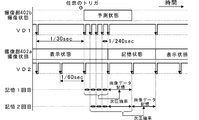
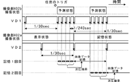
- FIG. 1 is a functional block diagram illustrating a schematic configuration of an imaging apparatus according to a first embodiment. It is explanatory drawing for demonstrating operation
- FIG. 11 is a functional block diagram illustrating a schematic configuration of an imaging apparatus according to Modification 1. It is a timing chart for demonstrating the production speed of image data. It is a timing chart for demonstrating the production speed of image data.
- image data refers to data for one screen generated by one imaging by the imaging device of the imaging unit.
- Imaging refers to an operation of generating image data through the imaging unit, and
- memory refers to an operation of storing the generated image data in a storage medium.
- continuous imaging refers to a series of operations that sequentially generate image data in the time direction. For example, one or more image data per second is generated as a result.
- the speed at which continuous imaging is performed and the image data is stored continuously is referred to as an imaging storage speed, and the imaging storage speed is a value of 1 sheet / sec or more, for example, 60 sheets / sec.
- Single-shot imaging refers to an operation for generating at least one piece of image data, and may include an operation for storing that single piece of image data, but before storing the image data, the image data is generated. It is not excluded to execute the operation to be performed multiple times.
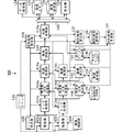
- FIG. 1 is a functional block diagram illustrating a schematic configuration of the imaging apparatus 100 according to the first embodiment.
- the imaging apparatus 100 includes an imaging unit 102, an imaging control unit 104, a synchronization signal generation unit (SSG: Synchronizing Signal Generator) 106, a timing generation unit (TG: Timing Generator) 108, a release switch 110, and a Y / C.
- SSG Synchronizing Signal Generator
- TG Timing Generator
- Processing unit 112 frequency response processing unit 114, gradation processing unit 116, compression processing unit 118, system internal bus 120, image memory 122, data control unit 124, image storage unit 126, display unit 128, the current compression rate deriving unit 130, the current compression rate holding unit 132, the next compression rate prediction unit 134, the frequency response deriving unit 136, the frequency response holding unit 138, the tone deriving unit 140, A holding unit 142, a quantization table deriving unit 144, and a quantization table holding unit 146 are configured.
- the frequency response processing unit 114, the gradation processing unit 116, and the compression processing unit 118 correct the compression rate of the image data generated by the imaging unit 102 based on the correction element, and perform intra-screen predictive coding. It functions as an image processing unit that performs compression encoding using a method.
- the frequency response deriving unit 136, the gradation deriving unit 140, and the quantization table deriving unit 144 function as a correction element deriving unit that derives a correction element.
- the correction element is one or more elements selected from the group of frequency response characteristics, gradation characteristics, and quantization tables used in the image processing unit. The frequency response characteristics, gradation characteristics, and quantization table will be described in detail later.
- the data control unit 124, the current compression rate deriving unit 130, the next compression rate prediction unit 134, the frequency response deriving unit 136, the gradation deriving unit 140, and the quantization table deriving unit 144 may be configured by hardware.
- the program may be implemented by software through a central processing unit (CPU) that operates in cooperation with a ROM storing a program, a RAM as a work area, and the like.
- the gradation processing unit 116 is cascaded subsequent to the frequency response processing unit 114, but this order may be reversed.
- the imaging unit 102 includes a lens and an imaging element that photoelectrically converts incident light incident through the lens and generates image data.
- the imaging unit 102 generates and generates a plurality of image data continuous in the time direction by continuous imaging.
- the plurality of pieces of image data are sequentially transmitted to the Y / C processing unit 112.
- the imaging control unit 104 controls the driving unit of the imaging unit 102 so that the focus, the aperture, and the zoom magnification of the imaging unit 102 are equal.
- the synchronization signal generation unit 106 generates a horizontal synchronization signal and a vertical synchronization signal in synchronization with the internal clock in correspondence with the horizontal size and the vertical size of the generated image data, and transmits them to the timing generation unit 108.
- the timing generation unit 108 generates a control signal for changing the clock timing of the image sensor of the imaging unit 102 based on the horizontal synchronization signal and the vertical synchronization signal generated by the synchronization signal generation unit 106.
- the imaging unit 102 generates image data according to the control signal.
- the release switch 110 is configured by a button switch or the like, receives an operation input from the photographer, and generates a control signal that serves as a trigger (trigger) for image data generation in the imaging unit 102. Further, in the imaging apparatus 100 of the present embodiment, continuous imaging can be performed by the photographer continuously holding the release switch 110.
- the Y / C processing unit 112 performs processing for separating and converting the image data into luminance data (Y) and color data (C).
- the frequency response processing unit 114 converts the frequency domain characteristics of the image data through the Y / C processing unit 112 based on the frequency response characteristics derived by the frequency response deriving unit 136 described later.
- the gradation processing unit 116 converts the gradation of the image data subjected to the frequency response characteristic conversion processing based on the gradation characteristic derived by the gradation deriving unit 140 described later.
- the compression processing unit 118 performs compression encoding processing based on the quantization table for the image data subjected to the gradation characteristic conversion processing according to the JPEG compression method, and the image data subjected to the compression encoding processing is The image data is transmitted to the image memory 122 through the system internal bus 120. Since the JPEG compression method is an existing technology, detailed description thereof is omitted here. The compression processing unit 118 can employ various existing still image compression methods other than the JPEG compression method.
- the image memory 122 is configured by a buffer such as SRAM or DRAM, and temporarily holds the image data transmitted from the compression processing unit 118.
- the data control unit 124 transfers the image data temporarily held in the image memory 122 to the image storage unit 126 through the system internal bus 120 to hold the image data, or the image data held in the image memory 122. An image based on the data is displayed on the display unit 128.
- the image storage unit 126 is configured by a storage medium such as a flash memory or an HDD formed integrally with the imaging device 100, and holds one or a plurality of image data.
- a storage medium such as a flash memory or an HDD formed integrally with the imaging device 100
- an optical disk medium such as a DVD or a BD (Blu-ray ⁇ ⁇ Disc)
- a magnetic medium such as a magnetic tape or a magnetic disk
- an external storage medium such as a flash memory, a portable HDD, or the like that is detachable from the imaging apparatus 100 You may apply.
- the HDD is precisely a device, but for the sake of convenience of explanation, in the present embodiment, it is treated as synonymous with other storage media.
- the display unit 128 includes a liquid crystal display, an organic EL (Electro Luminescence) display, or the like.
- the current compression rate deriving unit 130 compares the data capacity of the image data before the compression encoding process is performed by the compression processing unit 118 with the data capacity of the image data after the compression encoding process is performed, The current compression rate that is the latest and actual compression rate in the compression encoding process is derived.
- the derived current compression rate is sequentially held in the current compression rate holding unit 132.
- the current compression rate holding unit 132 holds a plurality of current compression rates derived by the current compression rate deriving unit 130 continuously in the time direction. Therefore, the current compression rate holding unit 132 holds the current compression rate for a plurality of past times.
- the next compression rate prediction unit 134 acquires the current compression rate over the past multiple times including the most recent current compression rate from the current compression rate holding unit 132, and the plurality of current compression rates or the plurality of held current compressions.
- the next compression rate that is the compression rate of the image data to be compressed and encoded next time is predicted from the rate and the compression rate of the image data to be compression encoded this time.
- the frequency response deriving unit 136 includes the previous frequency response characteristic held in the frequency response holding unit 138 and the next compression rate predicted by the next compression rate prediction unit 134 so that the predicted next compression rate approaches the target compression rate. And a frequency response characteristic used by the frequency response processing unit 114 is derived based on a preset target compression rate in continuous imaging.
- the gradation deriving unit 140 determines the previous gradation characteristics held in the gradation holding unit 142 and the next compression rate predicted by the next compression rate prediction unit 134 so that the predicted next compression rate approaches the target compression rate. And the gradation characteristics used by the gradation processing unit 116 are derived based on the preset target compression rate in continuous imaging.
- the quantization table deriving unit 144 uses the previous quantization table held in the quantization table holding unit 146 and the next compression predicted by the next compression rate prediction unit 134 so that the predicted next compression rate approaches the target compression rate.
- a quantization table used by the compression processing unit 118 is derived based on the compression rate and a preset target compression rate in continuous imaging.
- next compression rate prediction unit 134 obtains the current compression rate over the past plural times including the most recent current compression rate from the current compression rate holding unit 132, and the plurality of current compression rates or the plurality of current compression rates are held.
- the next compression rate which is the compression rate of the image data to be encoded next time, is predicted from the plurality of current compression rates and the compression rate of the image data to be compression encoded this time.
- the prediction of the next compression rate is performed using (1) average value, (2) difference value, and (3) change rate of a plurality of current compression rates.
- the derivation process of the next compression rate in each will be described in detail.
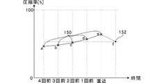
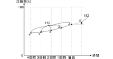
- FIG. 2 to 4 are explanatory diagrams for explaining the operation of the next compression rate prediction unit 134.
- FIG. 2 shows a case where (1) an average value is used
- FIG. 3 shows a case where (2) a difference value is used
- FIG. 4 shows a case where (3) a change rate is used.
- the next compression rate prediction unit 134 predicts the next compression rate 152 based on the current compression rate 150 for five times, including the most recent current compression rate and the current compression rate for the past four times.
- the number of current compression rates 150 used in the next compression rate prediction unit 134 is not limited to 5 and may be 2 or more.
- the next compression rate prediction unit 134 uses the following formula 1 to calculate the current compression rate 150 for the five times including the latest (a, b, c, d, The average value f of e) is obtained. ... (Formula 1) The average value f thus obtained becomes the next compression rate 152.
- the rate 152 can be derived.
- the next compression rate predicting unit 134 shows the current compression rate 150 for five times including the latest (a, b, c in FIG. 3).
- D, e) are obtained (b ⁇ a, c ⁇ b, d ⁇ c, ed), and a difference value between the current compression rates 150 adjacent to each other in the time direction is calculated, and the average value is calculated as the latest current compression rate 150.
- the value g using the difference value obtained in this way becomes the next compression rate 152.
- the difference value is used in this way, when the compression rate continues to change in one direction, such as a large amount of movement between images, or the change direction is biased, an appropriate follow-up change is followed.
- the next compression rate 152 can be derived.
- the next compression rate prediction unit 134 shows the current compression rate 150 for five times including the latest (a, b, c in FIG. 4).
- D, e) are obtained (b / a, c / b, d / c, e / d) between the current compression ratios 150 adjacent to each other in the time direction, and the average value is calculated as the latest current compression ratio 150.
- the value h using the change rate obtained in this way becomes the next compression rate 152. If the rate of change is used in this way, when the compression rate continues to change in one direction, such as a large amount of movement between images, or the direction of change is biased, an appropriate follow-up change is followed.
- the next compression rate 152 can be derived.
- the number of the current compression ratios 150 used by the next compression ratio prediction unit 134 may be two or more.
- the number of the current compression ratios 150 is a predetermined number as in the case of starting continuous imaging. If it is less, the next compression rate prediction unit 134 uses the most recent current compression rate 150 held in the current compression rate holding unit 132 as the next compression rate 152 as it is, or holds it in the current compression rate holding unit 132.
- the next compression rate 152 may be predicted by reflecting only the current compression rate 150 that is less than the predetermined number.
- the frequency response processing unit 114, the gradation processing unit 116, and the compression processing unit 118 are prepared in advance. Conversion processing or compression coding processing is performed based on the standard frequency response characteristics, gradation characteristics, and quantization table. These standard frequency response characteristics, gradation characteristics, and quantization tables are set based on a target compression rate set by the user through an external operation. Then, the next compression rate prediction unit 134 sets the current compression rate 150 of the image data obtained by the change processing and compression encoding processing as the next compression rate 152 as it is.
- the frequency response processing unit 114, the gradation processing unit 116, and the compression processing unit 118 perform the current compression for one time. Conversion processing or compression coding processing is performed based on the new frequency response characteristics, gradation characteristics, and quantization table derived from the next compression ratio 152 by the ratio 150.
- next compression rate prediction unit 134 holds the current compression rate less than the predetermined number held in the current compression rate holding unit 132 until the number of the current compression rate 150 reaches the predetermined number.
- the frequency response processing unit 114, the gradation processing unit 116, and the compression processing unit 118 predict new frequency response characteristics, gradation characteristics, and quantization derived from the next compression ratio 152. Conversion processing or compression encoding processing is performed based on the table.
- the data control unit 124 does not store in the image storage unit 126 the image data until the number of the current compression rate 150 reaches a predetermined number among the generated image data. You can even start remembering after you reach the number.
- the frequency response processing unit 114, the gradation processing unit 116, and the compression processing unit 118 are held in the current compression rate holding unit 132 until a predetermined number is reached from the imaging of the second image data in the continuous imaging.
- the conversion process or the compression encoding process is performed based on the new frequency response characteristic, gradation characteristic, and quantization table using the current compression ratio 150.
- the present invention is not limited to this.
- the conversion process or the compression encoding process may be performed based on standard frequency response characteristics, gradation characteristics, and a quantization table prepared in advance until a predetermined number is reached.
- time position at which the plurality of current compression ratios 150 are taken out is not limited to one or more times in the past and the past as described above, and may be a predetermined number in the past excluding the latest.
- next compression rate prediction unit 134 (1) the above-described process of averaging a predetermined number of current compression rates 150, and (2) the difference value between the current compression rates 150 adjacent to each other in the time direction of the current compression rate 150. (3) A process of multiplying the latest current compression ratio 150 by the average value of the rate of change of the current compression ratio 150 adjacent in the time direction of the current compression ratio 150, The processing of 2 or 3 selected from these groups may be switched according to the change mode (direction of change and magnitude) of the current compression rate 150 to predict the next compression rate 152.
- a process of averaging a predetermined number of current compression ratios 150 and (2) an average value of difference values of current compression ratios 150 adjacent to each other in the time direction of the current compression ratio 150 are the latest current compression ratios. It is assumed that the process of adding to 150 is combined so as to be switchable.
- the next compression rate prediction unit 134 monitors the change mode of the current compression rate 150. For example, the compression rate continuously changes in one direction, such as a large movement amount between images, or the change direction is biased.
- the next compression rate 152 is predicted using the difference value and an irregular image is captured, or when there is a large change in the compression rate in a short time, (1) the average value is used.
- the next compression rate 152 is predicted. In this way, by using an effective method for deriving the next compression ratio in accordance with the change mode of the current compression ratio 150, the data capacity of the image data after compression coding can be made closer to the target value with higher accuracy. It becomes possible.
- the correction of the compression rate of the image data is performed by the frequency response processing unit 114, the gradation processing unit 116, and the compression processing unit 118, each performing conversion processing or compression encoding processing based on the frequency response characteristics, gradation characteristics, and quantization table. It is done by doing. Therefore, by correcting (a) frequency response characteristics, (b) gradation characteristics, and (c) quantization table, the compression ratio of the image data changes relatively, and the current compression ratio is obtained throughout the continuous imaging. 150 can be brought close to the target compression rate.
- the target compression rate is a compression rate of 1 set by the photographer or selected from a plurality of options (imaging mode such as standard mode and fine mode).
- the target compression rate may be determined based on the data capacity per frame obtained by dividing the total data capacity that can be stored in one continuous imaging by the number of continuous imaging.
- the frequency response deriving unit 136 derives the frequency response characteristic used by the frequency response processing unit 114 based on the previous frequency response characteristic, the next compression rate 152, and the target compression rate.
- the frequency response deriving unit 136 first compares the next compression rate 152 predicted by the next compression rate prediction unit 134 with the target compression rate, and determines whether the compression effect should be reduced or increased. For example, when the frequency response characteristic is expressed as a frequency response characteristic by LPF (Low Pass Filter), if the frequency response deriving unit 136 determines that the compression effect should be reduced, the cut-off frequency fc (generally 30 ⁇ If it is determined that the compression effect should be increased (increase the pass bandwidth), the cut-off frequency fc of the LPF is decreased (narrow the pass bandwidth).
- LPF Low Pass Filter
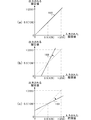
- FIG. 5 is an explanatory diagram for explaining the correction of the compression ratio based on the frequency response characteristics.
- the horizontal axis indicates the frequency
- the vertical axis indicates the response to the frequency.
- the frequency response deriving unit 136 converts the previously derived frequency response characteristic to the frequency response as shown in FIG. If it is obtained from the holding unit 138 (obtains the cut-off frequency fc of the previous LPF) and determines that the compression effect should be reduced, as shown in FIG. 5B, the cut-off frequency fc of the previous LPF is The frequency is increased by a frequency determined according to the difference value between the next compression rate 152 and the target compression rate.
- the frequency response deriving unit 136 determines that the compression effect should be increased, as shown in FIG. 5C, the frequency response deriving unit 136 sets the previous LPF cutoff frequency fc to the difference between the next compression rate 152 and the target compression rate. Decrease by the frequency determined according to the value.
- the reason why the frequency response characteristic is used for correcting the compression ratio is as follows. That is, in the image data, the larger the high frequency component, the larger the data capacity of the image data. Therefore, in order to bring the compression rate close to the target compression rate, the bandwidth of the image data may be adjusted at a stage before the compression encoding process is performed. Therefore, in this embodiment, when the compression effect of the next compression rate 152 is larger than the compression effect of the target compression rate, it is determined that the compression effect should be reduced, and the bandwidth of the frequency response characteristic is widened. If the compression effect is smaller than the compression effect of the target compression rate, it is determined that the compression effect should be increased, and the bandwidth of the frequency response characteristic is narrowed.
- the bandwidth of the frequency response characteristic is changed according to the difference value between the next compression ratio 152 and the target compression ratio, and the frequency response characteristic is obtained each time.
- the present invention is not limited to this case.
- a plurality of predetermined frequency response characteristics for example, a plurality of predetermined cut-off frequencies fc
- a difference value between the next compression ratio 152 and the target compression ratio and a plurality of frequency response characteristics are associated with each other.
- a suitable frequency response characteristic may be selected based on a difference value between the next compression ratio 152 and the target compression ratio.
- the frequency response deriving unit 136 transmits the new frequency response characteristic obtained in this way to the frequency response processing unit 114, and the frequency response processing unit 114 converts the image data based on the new frequency response characteristic. . Further, the frequency response deriving unit 136 overwrites the derived frequency response characteristic on the frequency response characteristic of the frequency response holding unit 138 to prepare for the next processing.
- the gradation deriving unit 140 derives the gradation characteristic used by the gradation processing unit 116 based on the previous gradation characteristic, the next compression rate 152, and the target compression rate.
- the gradation derivation unit 140 first compares the next compression rate 152 predicted by the next compression rate prediction unit 134 with the target compression rate, and determines whether the compression effect should be lowered or increased. When the gradation deriving unit 140 determines that the compression effect should be reduced, for example, the overall gradient of the gradation conversion curve (here, a straight line) that is the gradation characteristic should be increased to increase the compression effect. If it is determined, the overall gradient of the gradation conversion curve is reduced.
- the overall gradient of the gradation conversion curve here, a straight line
- FIG. 6 is an explanatory diagram for explaining the correction of the compression rate based on the gradation characteristics.
- the horizontal axis indicates the gradation value of the image data input to the gradation processing unit 116
- the vertical axis indicates the gradation value of the image data output from the gradation processing unit 116.
- the gradation deriving unit 140 acquires the previously derived gradation characteristic from the gradation holding unit 142 as illustrated in FIG. 6A (the inclination of the previous gradation conversion curve 160 (here, for example, the inclination). If “1”) is obtained) and it is determined that the compression effect should be lowered, as shown in FIG.
- the gradient of the previous gradation conversion curve 160 is changed between the next compression ratio 152 and the target compression ratio. Increase by the value determined according to the difference value.
- the gradient of the previous gradation conversion curve 160 is calculated between the next compression ratio 152 and the target compression ratio. Decrease by the value determined according to the difference value.
- the gradation conversion curve 160 is set so that the output gradation value is also 0.5. The offset of is adjusted.
- the reason why the gradation characteristic is used for correcting the compression rate is as follows. That is, in the image data, the greater the range that the gradation value can take, the greater the contrast, and the corresponding increase in the data capacity of the image data. Therefore, the compression effect must be increased accordingly.
- the contrast of the gradation value of the image data may be changed at a stage before the compression encoding process is performed. Therefore, in this embodiment, when the compression effect of the next compression rate 152 is larger than the compression effect of the target compression rate, it is determined that the compression effect should be reduced, and the gradient of the gradation conversion curve 160 which is the gradation characteristic is increased to increase the contrast. Conversely, if the compression effect of the next compression ratio 152 is smaller than the compression effect of the target compression ratio, it is determined that the compression effect should be increased, and the gradient of the gradation conversion curve 160 is lowered to reduce the contrast. .
- the gradation conversion curve 160 which is the gradation characteristic, has been described as an example of a straight line (primary curve). Can also be configured. In this case, the gradation derivation unit 140 may change the gradation conversion curve 160 so that the slope of the approximate straight line of the gradation conversion curve 160 is large or small. Moreover, although the example of 8-bit input and 8-bit output was shown as a gradation value, another bit value may be sufficient.
- the gradient conversion curve 160 which is the gradation characteristic, is changed in accordance with the difference value between the next compression ratio 152 and the target compression ratio, and the gradation characteristic is obtained each time.
- the present invention is not limited to this, and a plurality of predetermined tone characteristics (for example, slopes of a plurality of predetermined tone conversion curves 160), a difference value between the next compression rate 152 and the target compression rate, and a plurality of A gradation table corresponding to the inclination of the gradation conversion curve 160 is prepared, and an appropriate inclination of the gradation conversion curve 160 is determined based on the difference value between the next compression ratio 152 and the target compression ratio.
- a configuration may be selected.
- the processing load of the gradation deriving unit 140 can be reduced, and the gradation characteristics can be quickly obtained, so that the time spent for the compression encoding process of the image data can be shortened. It is also possible to shorten the generation interval.
- the gradation derivation unit 140 transmits the new gradation characteristic (the slope of the gradation conversion curve 160) obtained in this way to the gradation processing unit 116, and the gradation processing unit 116 transmits the new gradation characteristic.
- the image data is converted based on the characteristics. Further, the gradation deriving unit 140 overwrites the derived gradation characteristic on the gradation characteristic of the gradation holding unit 142 to prepare for the next process.
- the quantization table deriving unit 144 derives a quantization table used by the compression processing unit 118 based on the previous quantization table, the next compression rate 152, and the target compression rate.
- the quantization table is arranged with different coefficients for dividing the image data in order to omit relatively high frequency components of the image data after discrete cosine transform (DCT) in JPEG. For example, when an image block is represented by 8 pixels ⁇ 8 pixels, the table is similarly arranged with 8 ⁇ 8 coefficients.
- the quantization table deriving unit 144 first compares the next compression rate 152 predicted by the next compression rate prediction unit 134 with the target compression rate, and determines whether the compression effect should be lowered or increased. When the quantization table deriving unit 144 determines that the compression effect should be reduced, for example, when each coefficient of the quantization table is set to a relatively small value (divisor is small) and it is determined that the compression effect should be increased, Each coefficient of the quantization table is set to a relatively large value (divisor is large).
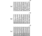
- FIG. 7 is an explanatory diagram for explaining the correction of the compression ratio by the quantization table 170.
- the quantization table 170 is represented by an array of 8 ⁇ 8 coefficients according to the image block. Further, the quantization table 170 is a coefficient corresponding to the low frequency component of the image block toward the upper left in FIG. 7, and is a coefficient corresponding to the high frequency component of the image block toward the lower right.
- the quantization table deriving unit 144 obtains the previously derived quantization table 170 as illustrated in FIG. 7A from the quantization table holding unit 146 and determines that the compression effect should be reduced, FIG.
- each coefficient is multiplied by 0.5 by a value determined according to the difference value between the next compression ratio 152 and the target compression ratio, thereby reducing each coefficient. If the quantization table deriving unit 144 determines that the compression effect should be increased, as shown in FIG. 7C, the quantization table deriving unit 144 determines a value determined according to the difference value between the next compression rate 152 and the target compression rate. For example, each coefficient is multiplied by 2 to increase each coefficient.
- the reason why the quantization table 170 is used for correcting the compression rate is as follows. That is, in the image data, the compression effect increases as the coefficients of the quantization table 170 increase, and the compression effect decreases as the coefficients of the quantization table 170 decrease. More specifically, for example, the data capacity of image data before compression is S, the predicted data capacity of image data after compression is Sa, the data capacity of target image data is Sb, and quantization is performed once before. Assuming that each coefficient of the table 170 is Qorg i, j (i, j are integers, which indicate the row and column of the quantization table 170, respectively), the coefficient Q i, j (i, j of the quantization table 170 to be obtained). Is an integer) using Equation 4. ... (Formula 4)
- Sa / S indicates the next compression ratio 152
- Sb / S indicates the target compression ratio.
- the current compression rate 150 is 20% when the quantization table 170 shown in FIG. 7A is used, the coefficient of the quantization table 170 shown in FIG. 7A is multiplied by 0.5.
- the current compression rate is 40%.
- the current compression rate is 10%.
- Such compression encoding processing is an example, and the compression rate changes depending on the content of the image data that is the basis, but the amount of change in the compression rate with respect to the ratio of the coefficients in the quantization table 170 has a substantially inverse relationship.
- the compression effect of the next compression rate 152 is larger than the compression effect of the target compression rate, it is determined that the compression effect should be reduced, and the coefficient of the quantization table 170 is lowered. If the compression effect is smaller than the compression effect of the target compression rate, it is determined that the compression effect should be increased, and the coefficient of the quantization table 170 is increased.
- the quantization table 170 is changed according to the difference value between the next compression ratio 152 and the target compression ratio, and the quantization table 170 is obtained each time.
- the present invention is not limited to this.
- a plurality of predetermined quantization tables 170 for example, FIGS. 7A, 7B, and 7C
- a difference value between the next compression rate 152 and the target compression rate and a plurality of quantization tables 170 may be prepared, and an appropriate one quantization table 170 may be selected based on a difference value between the next compression rate 152 and the target compression rate.
- the processing load of the quantization table deriving unit 144 can be reduced, and the quantization table 170 can be quickly obtained, so that the time spent for compression encoding processing of image data can be shortened. It is also possible to shorten the data generation interval.
- the quantization table deriving unit 144 transmits the new quantization table 170 thus obtained to the compression processing unit 118, and the compression processing unit 118 compresses the image data based on the new quantization table 170. Encoding process is performed. Also, the quantization table deriving unit 144 overwrites the derived quantization table 170 on the quantization table 170 of the quantization table holding unit 146 to prepare for the next processing.
- the compression rate correction is performed by all of the frequency response processing unit 114, the gradation processing unit 116, and the compression processing unit 118 has been described.
- the frequency response processing unit 114, the gradation processing unit 116, and the compression processing are performed. It is also possible to correct the compression rate with only one or two functional units selected from the unit 118.
- the function units to be adopted may be adopted in the order of the compression processing unit 118, the frequency response processing unit 114, and the gradation processing unit 116 in consideration of the degree of influence of the compression rate.
- the compression processing unit 118 directly performs the compression encoding process using the quantization table, it is easy to control the compression rate, and the frequency response processing unit 114 converts the existing LPF into the frequency response characteristics of this embodiment. Therefore, the gradation processing unit 116 can reduce the number of parts by using an existing amplifier circuit or gamma correction circuit for conversion of gradation characteristics. Further, when the compression rate is corrected by any one of the functional units or a combination of the two, the correction elements of the other functional units are fixed.
- FIG. 8 is a functional block diagram illustrating another example of the imaging apparatus 100.
- the compression processing unit 118 directly compresses and encodes the image data output from the gradation processing unit 116, but the gradation processing unit 116 performs the gradation characteristic conversion processing.
- the image data may be temporarily held in the image memory 122 through the system internal bus 120.
- the compression processing unit 118 acquires image data from the image memory 122 during or after the continuously captured image data is accumulated in the image memory 122, and compresses the image data based on the quantization table.
- the image data is transmitted to the image memory 122 through the system internal bus 120 again.
- Such a configuration in which the compression processing unit 118 temporarily stores the image data in the image memory 122 can also be used in a second embodiment described later.
- the generation of image data and the compression encoding process are made independent, only the generation of image data is performed during continuous imaging to reduce the time, and the compression encoding process is performed using a time other than during continuous imaging. To improve time efficiency.
- the image data can be quickly acquired from the image memory 122 during the compression encoding process, and the image data in the image memory 122 can be deleted at an early stage. Can be done.
- continuous imaging is executed with respect to generation of image data, and the data control unit 124 only selects the last compression-encoded image data among the plurality of compression-encoded image data.
- the single-shot imaging process can also be used in a second embodiment described later. With this configuration, the compression rate correction processing by continuous imaging can be used even in single-shot imaging, and the data capacity of image data in single-shot imaging can be brought close to a desired data capacity.
- a program that functions as the imaging device 100 by a computer and a storage medium that stores the program are also provided. Further, the program may be read from a storage medium and taken into a computer, or may be transmitted via a communication network and taken into a computer.
- Imaging method Next, a description will be given of an imaging method in which the above-described imaging device 100 is used to perform compression encoding processing on images that have been continuously captured (continuous shooting) and stored.
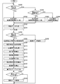
- FIG. 9 is a flowchart showing a processing flow of the imaging method according to the first embodiment.
- the imaging unit 102 of the imaging apparatus 100 When performing continuous imaging by the photographer, the imaging unit 102 of the imaging apparatus 100 generates a plurality of image data continuous in the time direction by continuous imaging (S202: imaging step), and the Y / C processing unit 112 performs image processing. A process of separating and converting the data into luminance data (Y) and color data (C) is performed (S204). Subsequently, the frequency response processing unit 114 converts the frequency domain characteristics of the image data through the Y / C processing unit 112 based on the frequency response characteristics derived by the frequency response deriving unit 136 (S206: Image).
- the gradation processing unit 116 converts the gradation of the image data that has been subjected to the frequency response characteristic conversion processing based on the gradation characteristic derived by the gradation derivation unit 140 described later (S208).
- the image processing step 2), the compression processing unit 118 performs compression encoding processing on the image data subjected to the gradation characteristic conversion processing based on the quantization table, and stores it in the image memory 122 through the system internal bus 120. Transmit (S210: Image processing step 3).
- the current compression rate deriving unit 130 compares the data capacity of the image data before the compression encoding process is performed by the compression processing unit 118 with the data capacity of the image data after the compression encoding process is performed,
- the current compression rate 150 which is the latest and actual compression rate in the compression encoding process is derived (S212: current compression rate deriving step), and the derived current compression rate 150 is held in the current compression rate holding unit 132 (S214: Current compression rate retention step).
- the next compression rate prediction unit 134 acquires the current compression rate held in the current compression rate holding unit 132 over the past multiple times including the most recent current compression rate, and the next compression rate is calculated from the plurality of current compression rates.
- the next compression rate that is the rate is predicted (S216: next compression rate prediction step).
- the prediction of the next compression rate is performed using any one of (1) average value, (2) difference value, and (3) change rate of a plurality of current compression rates.
- the frequency response processing unit 114, the gradation processing unit 116, and the compression processing unit 118 are respectively prepared in advance. Conversion processing or compression encoding processing is performed based on standard frequency response characteristics, gradation characteristics, and quantization tables. Then, the next compression rate prediction unit 134 sets the current compression rate 150 by the change process and the compression encoding process as the next compression rate 152. In the imaging of the second image data, the frequency response processing unit 114, the gradation processing unit 116, and the compression processing unit 118 use the new frequency derived from the next compression rate 152 by the current compression rate 150 for one time. Conversion processing or compression coding processing is performed based on the response characteristics, gradation characteristics, and quantization table.
- the frequency response deriving unit 136 derives a frequency response characteristic used by the frequency response processing unit 114 based on the previous frequency response characteristic held in the frequency response holding unit 138, the next compression rate 152, and the target compression rate (S218).
- the tone derivation unit 140 derives the tone characteristics used by the tone processing unit 116 based on the previous tone characteristics, the next compression rate 152, and the target compression rate held in the tone holding unit 142 (S220). : Correction element derivation step 2).
- the quantization table deriving unit 144 derives the quantization table used by the compression processing unit 118 based on the previous quantization table held in the quantization table holding unit 146, the next compression rate 152, and the target compression rate ( S222: Correction element derivation step 3).
- the frequency response deriving unit 136, the gradation deriving unit 140, and the quantization table deriving unit 144 use the frequency response table, the gradation table, and the quantization correspondence table, respectively, to obtain a frequency response characteristic, a gradation characteristic, and a quantum table.
- a conversion table may be selected.
- the data control unit 124 transfers the compression-encoded image data held in the image memory 122 to the image storage unit 126 through the system internal bus 120 and holds the image data (S224: data control). Step).
- the conventional method of repeatedly performing compression encoding processing takes a long time for compression encoding, and there has been a technique to execute without repeating compression encoding processing, but using only the compression rate of the immediately preceding image data Since the parameters for the next compression encoding were determined, the prediction accuracy was low.
- the next compression rate 152 is predicted from the current compression rate 150 of the immediately preceding plurality of image data.
- the imaging interval is shortened as the compression encoding speeds up, so that the compression rate can be appropriately predicted based on more similar image data.
- the compression rate does not become extremely out of value, It is possible to perform the compression encoding process at the time of continuous imaging with high accuracy and high speed.
- the imaging apparatus 100 described in the first embodiment it is possible to perform compression encoding processing with high accuracy and high speed by predicting the next compression rate from the current compression rate of a plurality of immediately preceding image data. .
- the imaging apparatus 100 refers to the current compression rate 150 of a plurality of image data over the past in order to predict the compression rate of image data to be stored, image data with an appropriate compression rate is stored. Until this is done, the imaging time required to generate a plurality of image data is required.
- image data is stored in the image storage unit 126 or at least image data is left in the image memory 122 for storage in the image storage unit 126.
- a certain imaging storage speed is 60 sheets / sec
- the compression encoding process is performed with high accuracy by controlling the generation speed of image data at the time of continuous imaging, and in a short time.
- the purpose is to start storing image data.
- FIG. 10 is a functional block diagram illustrating a schematic configuration of the imaging apparatus 300 according to the second embodiment.
- the imaging apparatus 300 includes an imaging unit 102, an imaging control unit 104, a synchronization signal generation unit 306, a timing generation unit 308, a release switch 110, a Y / C processing unit 112, a frequency response processing unit 114, a floor, Key processing unit 116, compression processing unit 118, system internal bus 120, image memory 122, data control unit 124, image storage unit 126, display unit 128, current compression rate deriving unit 130, current compression A rate holding unit 132, a next compression rate prediction unit 134, a frequency response deriving unit 136, a frequency response holding unit 138, a tone deriving unit 140, a tone holding unit 142, a quantization table deriving unit 144, And a quantization table holding unit 146.
- the synchronization signal generation unit 306 and the timing generation unit 308 function as a generation rate management unit that manages the generation rate
- a compression processing unit 118 a system internal bus 120, an image memory 122, a data control unit 124, an image storage unit 126, a display unit 128, a current compression rate deriving unit 130, a current compression rate holding unit 132, Next-order compression rate prediction unit 134, frequency response deriving unit 136, frequency response holding unit 138, tone deriving unit 140, tone holding unit 142, quantization table deriving unit 144, and quantization table holding unit 146 are substantially the same in function and will not be described repeatedly.
- the synchronization signal generation unit 306 and the timing generation unit 308 having different configurations are exemplified. In terms of changing the growth rate will be described. However, in the first embodiment, a plurality of current compression ratios are required to obtain the next compression ratio. However, in the second embodiment, the next compression ratio may be obtained only from the most recent current compression ratio.
- the synchronization signal generation unit 306 generates a horizontal synchronization signal and a vertical synchronization signal in correspondence with the horizontal size and vertical size of the generated image data, and transmits them to the timing generation unit 308.
- the timing generation unit 308 generates a control signal for changing the clock timing of the image sensor of the imaging unit 102 based on the horizontal synchronization signal and the vertical synchronization signal generated by the synchronization signal generation unit 306.
- the imaging element of the imaging unit 102 When receiving an optical signal from the outside, the imaging element of the imaging unit 102 outputs an image signal (image data) in synchronization with the clock timing.
- one of the purposes is to control the generation speed of imaging data by the imaging unit 102.
- the synchronization signal generation unit 306 increases the horizontal synchronization signal and the vertical synchronization in order to increase the generation speed of image data. In order to shorten the signal generation cycle, while reducing the generation rate of the image data, the generation cycle of the horizontal synchronization signal and the vertical synchronization signal is increased.
- a method for controlling the generation speed of image data will be described.
- the imaging unit 102 when the imaging unit 102 is driven with a predetermined clock, the upper limit of the data capacity of image data that can be read out per unit time from one output bus of the imaging device is determined. For this reason, generally, the higher the generation speed of image data, the smaller the data capacity of the generated image data, and the lower the generation speed of image data, the larger the data capacity of the image data.
- This is a technique using so-called pixel mixing, and a specific implementation method is disclosed in, for example, Japanese Patent Application Laid-Open No. 2006-217355.
- a plurality of output buses are provided, and image data is obtained simultaneously from the plurality of output buses at the same timing, whereby the image data generation speed is high. Also, it is possible to obtain image data having a large data capacity.
- the technique for providing the multiple output buses described above does not reduce the data capacity of the image data even if the image data generation speed increases. In other words, since the data capacity of the image data does not depend on the image data generation speed, it is possible to always set the image data generation speed high.
- a technique of providing a plurality of output buses is used, and it is assumed that the image data has the same data capacity even when the image data generation speed is switched.
- the synchronization signal generation unit 306 temporarily increases the generation speed of the image data of the imaging unit 102 in accordance with an arbitrary trigger from the imaging storage speed for the purpose of storing the image data, and at a predetermined timing after the arbitrary trigger.
- the arbitrary trigger is a preparation process for storing image data.
- the photographer presses the release switch 110 halfway to cause the autofocus of the imaging unit 102 to function.
- the imaging unit 102 moves the focus lens to focus on the subject, and also makes the image data generation speed higher than the imaging storage speed.
- the next compression rate 152 is predicted quickly using image data generated at a high generation speed.
- the preparatory process is not limited to the above-described autofocus function start operation, but is a start operation for detecting a smile of a subject, a start operation for detecting a change in an image within a predetermined image range, or an image memory for image data. It may be an auto timer setting operation that uses a timer for the storage timing to 122.
- the image data generation speed is returned to the imaging storage speed, and the image memory 122 is stored. Be started.
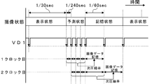
- FIG. 11 is a timing chart for explaining changes in the generation speed of image data.
- the imaging state for example, a storage state for the purpose of storing image data, a prediction state for predicting the next compression rate 152 mainly for compression encoding of image data, and a preceding stage thereof.
- the three state transitions of the display state in which the image data is mainly displayed on the display unit 128 in order to browse the generated image data are shown.
- the synchronization signal generation unit 306 sets the image data generation speed to 60 frames / sec (period 1/60 sec) equal to the imaging storage speed in the display state until an arbitrary trigger occurs, and the data control unit 124 generates Image data is displayed on the display unit 128.
- the imaging state is changed from the display state to the predicted state.
- the synchronization signal generator 306 controls the vertical synchronization signal VD1 to switch the image data generation speed to, for example, 240 images / sec (cycle 1/240 sec) (60 images / sec), which is higher than the imaging storage speed. sec ⁇ 240 sheets / sec).
- the synchronization signal generation unit 306 controls the vertical synchronization signal VD1 to switch the image data generation speed to the imaging storage speed (240 images / sec ⁇ 60 images / sec). .
- the data control unit 124 starts storing the image data held in the image memory 122 in the image storage unit 126.
- the image data is compressed and encoded at an appropriate compression rate in the storage state.
- FIG. 11 will be described.
- the imaging apparatus 300 transitions the imaging state to the prediction state, and the image processing unit (frequency response processing unit 114, gradation processing unit 116, compression processing unit). 118) starts the correction of the compression rate of the image data, and the correction element deriving unit (frequency response deriving unit 136, gradation deriving unit 140, quantization table deriving unit 144) is a correction element necessary for correcting the compression rate.
- the current compression ratio 150 is held in the current compression ratio holding unit 132 by the first vertical synchronization signal VD1 in the predicted state.
- the prediction state continues for four clocks of the vertical synchronization signal VD1.
- the imaging state transitions from the predicted state to the storage state.
- the next compression rate prediction unit 134 can appropriately predict the next compression rate 152 based on the average value of the four current compression rates 150 accumulated in the prediction state.
- the deriving unit 136, the gradation deriving unit 140, and the quantization table deriving unit 144) appropriately correct the correction elements based on the next compression rate 152 and the target compression rate from the first clock of the vertical synchronization signal VD1 in the storage state.
- the image processing unit (frequency response processing unit 114, gradation processing unit 116, compression processing unit 118) can correct the compression rate of the image data based on the appropriate correction factor. .
- the image data thus compression-encoded is stored in the image storage unit 126 by the data control unit 124, for example.
- the next compression rate prediction unit 134 includes the three current compression rates 150 acquired immediately before in the prediction state and the current compression rate 150 of the first image data in the storage state.
- the next compression rate is predicted based on the average value and the like. Therefore, the compression rate between the three image data generated at 240 images / sec and the one image data generated at 60 images / sec is referred to.
- the synchronization signal generation unit 306 and the timing generation unit 308 are used to match the image data generation speed of the imaging unit 102 and the storage speed of the image data stored in the image storage unit 126 of the data control unit 124.
- continuous imaging can be performed smoothly.
- the data control unit 124 stores two image data in the image storage unit 126. Automatically changes to the display state.
- the image data generation speed is maintained at the imaging storage speed (60 images / sec).
- the upper limit of the number of image data to be stored in continuous imaging is two, but it is of course possible to set it to one or three or more.
- the number of the current compression ratios 150 for predicting the next compression ratio 152 is four, but the number of the current compression ratios 150 may be one or more.
- the correction element deriving unit takes into account the reduction of high-frequency components by switching the generation rate of image data as parameters for deriving correction elements. There is a need to.
- Compressed encoding operates as follows by switching the image data generation speed described above. That is, the current compression rate 150 is stored at a high speed (a higher speed than the imaging storage speed) before the storage of the image data in the image memory 122 is started, and an appropriate next compression ratio is predicted in a short time, and thereafter Continues correction of the compression rate at the imaging storage speed.
- the generation interval of image data is short, not only the time required for prediction of the next compression rate 152 is shortened, but also the continuous image data becomes an approximate image, and the prediction accuracy of the next compression rate 152 is improved.
- the synchronization signal generation unit 306 determines the generation speed of the image data of the imaging unit 102 until the arbitrary trigger occurs and after the last compression-coded image data is stored in the image storage unit. It may be lower.
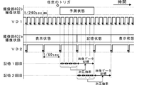
- FIG. 12 is a timing chart for explaining another example of the change in the generation speed of the image data. Also in FIG. 12, three state transitions of the storage state, the prediction state, and the display state are shown as the imaging state.
- FIG. 12 shows a vertical synchronization signal VD1 for generating image data, compression encoding, and storing the image data in the image storage unit 126.
- the vertical synchronization signal VD1 changes according to the imaging state.
- the synchronization signal generation unit 306 has a generation rate of image data of 30 images / sec (period 1/60 sec), which is lower than the image capture storage speed of 60 images / sec (period 1/60 sec) in a display state until an arbitrary trigger occurs. 30 sec), the data control unit 124 causes the display unit 128 to display the generated image data.
- the image data generation speed is 30 sheets / sec.
- the imaging state is changed from the display state to the predicted state.
- the synchronization signal generation unit 306 controls the vertical synchronization signal VD1 to switch the image data generation speed to, for example, 240 sheets / sec (cycle 1/240 sec) higher than the imaging storage speed (30 sheets / 240 sec). sec ⁇ 240 sheets / sec).
- the synchronization signal generation unit 306 controls the vertical synchronization signal VD1 to switch the image data generation speed to the imaging storage speed (240 images / sec ⁇ 60 images / sec). .
- the data control unit 124 starts storing the image data held in the image memory 122 in the image storage unit 126 based on the vertical synchronization signal VD1 switched to the imaging storage speed.
- the image data is compressed and encoded at an appropriate compression rate in the storage state.
- the synchronization signal generation unit 306 and the timing generation unit 308 control the vertical synchronization signal VD1 so that the image data generation speed becomes the imaging storage speed, and the compression processing unit 118
- the image data compressed and encoded in accordance with the storage timing of the image data by the data control unit 124 is transmitted to the image memory 122. Therefore, it is possible to efficiently execute from generation to storage of image data, and to realize overall time reduction of compression encoding.
- the imaging apparatus 300 displays image data on the display unit 128 at 30 sheets / sec in order to reduce power consumption and heat generation until an arbitrary trigger is received.
- the imaging state of the imaging apparatus 300 becomes a predicted state, and the image processing unit (frequency response processing unit 114, gradation processing unit 116, compression processing unit 118) starts correcting the compression rate of the image data.
- the correction element deriving unit (frequency response deriving unit 136, gradation deriving unit 140, quantization table deriving unit 144) starts deriving correction elements necessary for correcting the compression rate.
- the current compression ratio 150 is held in the current compression ratio holding unit 132 by the first vertical synchronization signal VD1 in the predicted state.
- the prediction state continues for four clocks of the vertical synchronization signal VD1.
- the imaging state transitions from the predicted state to the storage state.
- the next compression rate prediction unit 134 can appropriately predict the next compression rate 152 based on the average value of the four current compression rates 150 accumulated in the prediction state.
- the deriving unit 136, the gradation deriving unit 140, and the quantization table deriving unit 144) appropriately correct the correction elements based on the next compression rate 152 and the target compression rate from the first clock of the vertical synchronization signal VD1 in the storage state.
- the image processing unit (frequency response processing unit 114, gradation processing unit 116, compression processing unit 118) can correct the compression rate of the image data based on the appropriate correction factor. .
- the image data thus compression-encoded is stored in the image storage unit 126 by the data control unit 124, for example.
- the next compression rate prediction unit 134 includes the three current compression rates 150 acquired immediately before in the prediction state and the current compression rate 150 of the first image data in the storage state.
- the next compression rate is predicted based on the average value and the like. Therefore, the compression rate between the three image data generated at 240 images / sec and the one image data generated at 60 images / sec is referred to.
- the state transition of FIG. 12 will be described from the viewpoint of the photographer.
- the imaging state when no operation is performed is the display state, and the photographer can display the subject when the image data is generated through the display unit 128.
- the position and size can be confirmed.
- the generation speed of the image data at this time is set to a low value (for example, 30 sheets / sec) within a range that the image data update speed on the display unit 128 can accept.
- the image capturing apparatus 300 When the photographer presses the release switch 110 halfway, the image capturing apparatus 300 performs an autofocus function to focus on the subject, transitions the image capturing state to the predicted state, and generates a high image data generation speed (for example, 240 sheets / sec), the prediction of the next compression rate 152 in the compression encoding process is started. Subsequently, when the photographer fully presses the release switch 110, the imaging apparatus 300 changes the imaging state to the storage state, switches the image data generation speed to the image data storage speed (60 frames / sec), and continuously. The captured image data is stored. When the photographer opens the release switch 110, the imaging apparatus 300 returns the image data generation speed to a low value (for example, 30 images / sec).
- a low value for example, 30 images / sec.
- the imager can arbitrarily determine the image capturing and storage timing by operating the release switch 110 and the like, and can take advantage of the high accuracy and high speed compression encoding processing according to the present embodiment.
- Image data can be generated at a desired timing.
- a program that functions as the imaging device 300 by a computer and a storage medium that stores the program are also provided. Further, the program may be read from a storage medium and taken into a computer, or may be transmitted via a communication network and taken into a computer.
- Imaging method Next, a description will be given of an imaging method in which the above-described imaging device 300 is used to perform compression encoding processing on images that have been continuously captured (continuous shooting) and stored.
- FIG. 13 is a flowchart showing a flow of processing of the imaging method according to the second embodiment. Also here, since the processing (S202 to S224) already described in the imaging method in the first embodiment is substantially the same processing, redundant description is omitted.
- the imaging method first, it is determined whether or not the imaging state is the predicted state or the storage state (S350), and the synchronization signal is displayed while the imaging state is the standard display state (NO in S350).
- the generation unit 306 sets the imaging data generation speed to be lower than the imaging storage speed (S352).
- the imaging state is a predicted state or a storage state (S354), and the imaging state is determined. Is in the display state (NO in S354), the imaging apparatus 300 directly stores the generated image data in the image memory 122 without performing compression encoding processing (S356). The image data held in the image memory 122 is displayed on the display unit 128. When the image data holding process S356 is completed, the process returns to the imaging state determination step S350.
- the imaging state transitions from the display state to the predicted state. If it is determined in the imaging state determination step S350 that the imaging state is a predicted state (YES in S350), it is determined whether or not the imaging state is a storage state (S358). If the imaging state is not the storage state, that is, if the imaging state is the prediction state (NO in S358), the synchronization signal generator 306 sets the image data generation speed higher than the imaging storage speed (S360).
- the imaging state determination step S354 If it is determined in the imaging state determination step S354 that the imaging state is the predicted state (YES in S354), compression encoding processing (S206 to S222) is performed. Then, it is determined whether or not the imaging state is the storage state (S362). If the imaging state is not the storage state (NO in S362), the process returns to the imaging state determination step S350.
- the imaging state transitions from the predicted state to the memory state.
- the imaging state determination step S350 determines that the imaging state is the storage state (YES in S350)
- the imaging state determination step S358 it is determined that the imaging state is the storage state (YES in S358).
- the synchronization signal generator 306 sets the image data generation speed to the imaging storage speed (S364).
- the compression encoding process (S206 to S222) is performed as in the prediction state.
- the imaging state determination step S362 determines whether the imaging state is the storage state (YES in S362)
- the image data is stored in the image storage unit 126 by the data control unit 124 (S224).
- the image data holding process S224 is completed, the process returns to the imaging state determination step S350.
- the next compression rate 152 is predicted from the current compression rate 150 of the immediately preceding one or a plurality of image data.
- the change in the time direction of the image data can be properly grasped, and the compression rate can be brought closer to the target compression rate with higher accuracy.
- the generation speed of image data it is possible to predict the compression rate of the image data with higher accuracy and speed, and in the display state that does not affect the storage of the image data, power consumption and heat generation Can be reduced. Such an effect can be expected not only in continuous imaging but also in single-shot imaging.
- the third embodiment proposes an imaging apparatus 400 that can perform compression encoding processing at the time of continuous imaging with high accuracy and high speed while maintaining a stable storage operation.
- Imaging device 400 There is a stereoscopic image technique in which two images having horizontal parallax are presented on a display unit, and the viewer perceives the subject image as if it exists stereoscopically.
- the two images used in this technique are images captured based on each of a plurality of different optical axes (viewpoints) by a plurality of imaging units. The user can perceive the subject three-dimensionally by visually recognizing the two images with the left and right eyes.
- an imaging apparatus provided with a plurality of imaging units, it is possible to capture a 2D image through one imaging unit (storage imaging unit) of the plurality of imaging units as well as a stereoscopic image.
- the imaging apparatus performs continuous imaging through the storage imaging unit, and appropriately sets the compression rate in the compression encoding process in the continuous imaging independently from the storage imaging unit through another imaging unit (predictive imaging unit). To control. Therefore, it is possible to perform the compression encoding process at the time of continuous imaging with high accuracy and high speed while maintaining a stable storage operation.
- a schematic configuration of the imaging device will be described, and the image data generation speed of the storage imaging unit and the prediction imaging unit will be described in detail.
- FIG. 14 is a functional block diagram illustrating a schematic configuration of the imaging apparatus 400.
- the imaging apparatus 400 includes an imaging unit 402 (indicated by 402a and 402b in FIG. 14), an imaging control unit 404, a synchronization signal generation unit (SSG: Synchronizing Signal Generator) 406, and a timing generation unit (TG: Timing Generator). 408, a release switch 110, a Y / C processing unit 412 (indicated by 412a and 412b in FIG. 14), a frequency response processing unit 414 (indicated by 414a and 414b in FIG. 14), and gradation.
- a processing unit 416 (indicated by 416a and 416b in FIG.
- a compression processing unit 418 (indicated by 418a and 418b in FIG. 14), a system internal bus 120, an image memory 122, and a data control unit 124.
- An image storage unit 126 a display unit 128, a current compression rate deriving unit 130, a current compression rate holding unit 132, and a next compression rate prediction unit 134.
- the current compression rate deriving unit 130, the current compression rate holding unit 132, the next compression rate prediction unit 134, the frequency response deriving unit 136, the frequency response holding unit 138, the tone deriving unit 140, and the tone holding unit 142, the quantization table deriving unit 144, and the quantization table holding unit 146 are substantially the same in function, and thus redundant description thereof will be omitted.
- the imaging unit 402, the imaging control unit 404, and the like having different configurations are described.
- the imaging units 402a and 402b include a lens, an imaging element that photoelectrically converts incident light incident through the lens and generates image data, a driving unit that moves the optical axis, and the like, for example, continuous in the time direction by continuous imaging.
- a plurality of image data are generated, and the generated plurality of image data are sequentially transmitted to the Y / C processing units 412a and 412b, respectively.
- the imaging units 402a and 402b may be arranged such that both optical axes are positioned on a horizontal plane in the reference posture, and the two optical axes may intersect at an angle of convergence.
- the left-eye imaging unit 402a in the case of capturing a stereoscopic image is used as a storage imaging unit for generating and storing 2D image data
- the right-eye imaging unit 402b is used in compression encoding processing. It is used as a predictive imaging unit for performing compression rate prediction processing.
- the imaging control unit 404 controls the driving units of the imaging units 402a and 402b so that the focal points, the apertures, and the zoom magnifications of the two imaging units 402a and 402b are equal.
- the convergence angle is adjusted by rotating the optical axes of the imaging units 402a and 402b by the same angle in opposite directions around an axis perpendicular to the plane including the optical axis.
- the convergence point is positioned at the focal position (subject position) of the imaging unit 402a, which is a storage imaging unit, so that the focal point and angle of view of the imaging unit 402b are made equal to the focal point and angle of view of the imaging unit 402a. It is possible to predict the compression rate with high accuracy by using approximate image data.
- the synchronization signal generation unit 406 generates a horizontal synchronization signal and a vertical synchronization signal in synchronization with the internal clock in correspondence with the horizontal size and vertical size of the generated image data, and transmits them to the timing generation unit 408.
- the timing generation unit 408 generates a control signal for changing the clock timing of the image sensor of the imaging unit 402 based on the horizontal synchronization signal and the vertical synchronization signal generated by the synchronization signal generation unit 406.
- the imaging unit 402 generates image data according to the control signal.
- the synchronization signal generator 406 since one of the purposes is to control the generation speed of the imaging data by the imaging unit 402b, the synchronization signal generator 406 generates a horizontal synchronization signal in order to increase (fasten) the generation speed of the image data.
- the generation cycle of the horizontal synchronization signal and the vertical synchronization signal is lengthened in order to shorten the generation cycle of the vertical synchronization signal, while reducing the generation speed of the image data.
- the Y / C processing units 412a and 412b perform processing for separating and converting the image data into luminance data (Y) and color data (C).
- the frequency response processing units 414a and 414b convert the frequency domain characteristics of the image data through the Y / C processing units 412a and 412b based on the frequency response characteristics derived by the frequency response deriving unit 136 described later.
- the gradation processing units 416a and 416b convert the gradation of the image data subjected to the frequency response characteristic conversion processing based on the gradation characteristic derived by the gradation derivation unit 140 described later.
- the compression processing units 418a and 418b perform compression coding processing on the image data subjected to the gradation characteristic conversion processing according to the JPEG compression method based on the quantization table, and the compression processing unit 418a performs compression coding.
- the processed image data is transmitted to the image memory 122 through the system internal bus 120, and the compression processing unit 418b transmits the image data subjected to the compression encoding process to the current compression rate deriving unit 130.
- the synchronization signal generation unit 406 in the imaging apparatus 400 adjusts the generation cycle of the horizontal synchronization signal and the vertical synchronization signal, and sets the image data generation speed in the imaging unit 402b and the image data generation speed in the imaging unit 402a. Make it higher.
- the synchronization signal generation unit 406 is configured to capture the image data in the image capturing unit 402b when the image data generation speed (imaging storage speed) in the image capturing unit 402a is fixed to 60 frames / sec (period 1/60 sec: 60 fps).
- the generation speed of the image data is controlled to be the first generation speed, for example, 240 sheets / sec (period 1/240: 240 fps).
- a compression rate prediction process using the imaging unit 402b is started at a predetermined timing after an arbitrary trigger.
- the arbitrary trigger is a preparation process for storing image data.
- the imaging apparatus 400 quickly predicts the next compression rate 152 using image data generated at a high generation speed (240 images / sec) in the imaging unit 402b.
- the imaging unit 402a starts continuous imaging and storage of the generated image data.
- the preparatory process is not limited to the above-described autofocus function start operation, but is a start operation for detecting a smile of a subject, a start operation for detecting a change in an image within a predetermined image range, or an image memory for image data. It may be an auto timer setting operation that uses a timer for the storage timing to 122.
- FIG. 15 is a timing chart for explaining the generation speed of image data.
- the imaging state for example, a “storage state” for storing image data generated by the imaging unit 402 a and the preceding stage
- the image generation unit 402 b generates mainly for compression encoding of the image data.
- the data control unit 124 causes the display unit 128 to display the image data generated by the imaging unit 402a at 60 images / sec (period 1/60 sec) equal to the imaging storage speed. Yes.
- the imaging unit upon receiving an arbitrary trigger (for example, an autofocus function start operation) that is a preparation process for storing image data through the operation of the release switch 110 by the imager, the imaging unit at a predetermined timing thereafter.
- the imaging state of 402b becomes a prediction state, and the imaging unit 402b generates image data at 240 frames / sec (cycle 1/240 sec), which is higher than the imaging storage speed, and compression rate prediction processing is performed at the same generation speed.
- the compression rate prediction process is started in response to an arbitrary trigger for reducing power consumption and heat generation, but the compression rate prediction process can be always performed.
- the imaging unit When a predetermined time elapses from an arbitrary trigger, or when a new trigger (for example, full press operation) is obtained through the operation of the release switch 110 of the photographer after the elapse of the predetermined time from the arbitrary trigger, the imaging unit The imaging state 402a transitions from the display state to the storage state. Then, the data control unit 124 starts storing the image data held in the image memory 122 in the image storage unit 126.
- the imaging apparatus 400 transitions the imaging state of the imaging unit 402b to a predicted state, and image processing units (frequency response processing units 414a and 414b, gradation processing).
- the units 416a and 416b and the compression processing units 418a and 418b) start correcting the compression rate of the image data, and the correction element deriving unit (frequency response deriving unit 136, gradation deriving unit 140, and quantization table deriving unit 144) Derivation of correction factors necessary for correction of the compression ratio begins.
- the current compression rate 150 is held in the current compression rate holding unit 132 at the first clock of the predicted state in the vertical synchronization signal VD1 of the imaging unit 402b.
- the prediction state continues for four clocks of the vertical synchronization signal VD1.
- the imaging state of the imaging unit 402a changes from the display state to the storage state.
- the next compression rate prediction unit 134 can appropriately predict the next compression rate 152 based on the average value of the four current compression rates 150 accumulated in the prediction state.
- the deriving unit 136, the gradation deriving unit 140, and the quantization table deriving unit 144) can appropriately determine a correction element based on the next compression rate 152 and the target compression rate, and the image processing unit (frequency response unit).
- the processing unit 414a, the gradation processing unit 416a, and the compression processing unit 418a) compress the image data based on the appropriate correction element from the first clock of the storage state in the vertical synchronization signal VD2 of the imaging unit 402a in the storage state.
- the rate can be corrected.
- the image data compression-encoded by the compression processing unit 418a in this way is stored in the image storage unit 126 by the data control unit 124 (first storage).
- next compression rate prediction unit 134 predicts the next compression rate based on the average value of the four current compression rates 150 acquired immediately before the imaging unit 402b in the prediction state, and the image processing unit The compression rate of the image data can be corrected based on the appropriate correction element.
- the upper limit of the number of image data to be stored in continuous imaging is two, but it is of course possible to set it to one or three or more.
- the number of the current compression ratios 150 for predicting the next compression ratio 152 is four, but the number of the current compression ratios 150 may be one or more.
- the accumulation of the current compression rate 150 before the storage of the image data generated by the imaging unit 402a in the image memory 122 is started using the imaging unit 402b (the imaging storage speed). Higher speed) and predict the appropriate next compression rate in a short time.
- the generation interval of image data is short, not only the time required for prediction of the next compression rate 152 is shortened, but also the continuous image data becomes an approximate image, and the prediction accuracy of the next compression rate 152 is improved.
- the generation speed of image data of either of the imaging units 402a and 402b can be fixed, it is a case where an imaging device that does not support switching of the frame rate or has a restriction is used. However, there is an advantage that the effect can be obtained, and the selection range of the image sensor is widened.
- the synchronization signal generation unit 406 first generates the image data of the imaging unit 402b from when the data control unit 124 starts storing the compression-encoded image data to the image storage unit 126 until an arbitrary trigger is generated. It is also possible to generate at a second generation speed lower than the speed, or not to generate image data.
- the synchronization signal generation unit 406 performs the second generation of the image data generation rate of the imaging unit 402b while fixing the image data generation rate (imaging storage speed) in the imaging unit 402a to 60 images / sec.
- the speed is controlled to be, for example, 30 sheets / sec (period 1/30 sec: 30 fps), and the image data generation speed of the imaging unit 402b is changed from 30 sheets / sec at a predetermined timing after an arbitrary trigger. Switch to 240 frames / sec, which is higher than the imaging storage speed.
- the image data generation speed is switched by changing the frame rate of the image sensor of the imaging unit 402b.
- the arbitrary trigger is a preparation process for storing the above-described image data.
- the image data generation speed of the imaging unit 402b is returned to 30 sheets / sec, and the imaging unit 402a
- the storage of the image data generated in step S1 into the image memory 122 is started.
- the image data generation speed is set to 30 sheets / sec.
- the image data generation speed is not limited to this, and an arbitrary generation speed may be used.
- the image data itself is not generated (0 sheets / sec). It can also be.
- FIG. 16 is a functional block diagram showing a schematic configuration of the imaging apparatus 500 in the first modification
- FIG. 17 is a timing chart for explaining the generation speed of the image data.
- an image switching unit 548 that switches the input source of image data to the compression processing unit 418a between the gradation processing unit 416b and the gradation processing unit 416a is added to the imaging apparatus 400 described above. Is different.
- the data control unit 124 causes the display unit 128 to display the image data generated by the imaging unit 402a at 60 images / sec (period 1/60 sec) equal to the imaging storage speed. Yes.
- the imaging state of the imaging unit 402b becomes a predicted state at a predetermined timing thereafter
- the synchronization signal generation unit 406 controls the vertical synchronization signal VD1 to switch the image data generation rate of the imaging unit 402b to a higher rate than the imaging storage rate, for example, 240 images / sec (cycle 1/240 sec).
- the compression rate prediction process is performed.
- the imaging unit When a predetermined time elapses from an arbitrary trigger, or when a new trigger (for example, full press operation) is obtained through the operation of the release switch 110 of the photographer after the elapse of the predetermined time from the arbitrary trigger, the imaging unit The imaging state of 402a transitions from the display state to the storage state, and at the same time, the synchronization signal generation unit 406 controls the vertical synchronization signal VD1 so that the image data generation rate of the imaging unit 402b is 30 frames / sec. Switch (240 sheets / sec ⁇ 30 sheets / sec). Then, the data control unit 124 starts storing the image data held in the image memory 122 in the image storage unit 126.
- a new trigger for example, full press operation
- the imaging apparatus 500 receives an arbitrary trigger
- the imaging state of the imaging unit 402b transitions to a predicted state
- the synchronization signal generation unit 406 generates image data of the imaging unit 402b.
- the speed is switched from 30 sheets / sec to 240 sheets / sec
- the image processing unit (frequency response processing units 414a, 414b, gradation processing units 416a, 416b, compression processing unit 418a) starts correcting the compression rate of the image data.
- the correction element deriving unit (frequency response deriving unit 136, gradation deriving unit 140, quantization table deriving unit 144) starts deriving correction elements necessary for correcting the compression rate.
- the current compression rate 150 is held in the current compression rate holding unit 132 at the first clock of the predicted state in the vertical synchronization signal VD1 of the imaging unit 402b.
- the prediction state continues for four clocks of the vertical synchronization signal VD1.
- the imaging state of the imaging unit 402a changes from the display state to the storage state.
- the next compression rate prediction unit 134 can appropriately predict the next compression rate 152 based on the average value of the four current compression rates 150 accumulated in the prediction state.
- the deriving unit 136, the gradation deriving unit 140, and the quantization table deriving unit 144) can appropriately determine a correction element based on the next compression rate 152 and the target compression rate, and the image processing unit (frequency response unit).
- the processing unit 414a, the gradation processing unit 416a, and the compression processing unit 418a) compress the image data based on the appropriate correction element from the first clock of the storage state in the vertical synchronization signal VD2 of the imaging unit 402a in the storage state. The rate can be corrected.
- the image data compression encoded by the compression processing unit 418a is stored in the image storage unit 126 by the data control unit 124 (first storage), for example. Further, the synchronization signal generation unit 406 controls the vertical synchronization signal VD1 at a timing corresponding to the first clock of the storage state in the vertical synchronization signal VD2, and returns the image data generation rate of the imaging unit 402b to 30 sheets / sec. .
- the next compression rate prediction unit 134 includes the three current compression rates 150 acquired immediately before in the prediction state of the imaging unit 402b, and the other current compression rate 150.
- the next compression rate is predicted based on the average value of.
- the synchronization signal generation unit 406 obtains image data because the image data generation rate of the imaging unit 402b has been returned to 30 sheets / sec or image data has not been generated. I can't.
- the image switching unit 548 switches the input source of the image data to the compression processing unit 418a from the gradation processing unit 416b to the gradation processing unit 416a, whereby the current compression rate of the first image data in the storage state.
- the compression rate between the three image data generated at 240 images / sec and the one image data generated at 60 images / sec is referred to.
- the image processing unit can correct the compression rate of the image data based on the appropriate correction element (second storage).
- the current compression rate 150 is accumulated at a high speed (imaging storage speed) before the storage of the image data generated by the imaging unit 402a in the image memory 122 is started. Higher speed) and predict the appropriate next compression rate in a short time.
- the generation interval of image data is short, not only the time required for prediction of the next compression rate 152 is shortened, but also the continuous image data becomes an approximate image, and the prediction accuracy of the next compression rate 152 is improved.
- the image data of the imaging unit 402b By reducing the generation speed and not generating image data, it is possible to reduce power consumption and heat generation.
- the image switching unit 548 is used to predict the compression rate using the image data of the imaging unit 402b from the first clock of the storage state in the vertical synchronization signal VD2 of the imaging unit 402a in the storage state. Since processing is not performed, it is not necessary to perform compression processing in parallel between the imaging unit 402b and the imaging unit 402a. Therefore, as shown in FIG. 16, one compression processing unit 418b can be omitted, and the number of parts can be reduced, and power consumption and heat generation can be reduced.
- the synchronization signal generation unit 406 of the imaging apparatus 400 receives the image data of the imaging unit 402b from when the data control unit 124 starts storing the compression-encoded image data in the image storage unit 126 until an arbitrary trigger occurs. Each time the data control unit 124 stores the compressed and encoded image data in the image storage unit 126 after generating the second generation rate lower than the first generation rate or not generating the image data.
- the image data of the imaging unit 402b may be generated at the first generation speed for a predetermined period until the storage is performed.
- the synchronization signal generation unit 406 performs the second generation of the image data generation speed of the imaging unit 402b while fixing the generation speed (imaging storage speed) of the image data in the imaging unit 402a to 30 frames / sec. For example, at a predetermined timing after an arbitrary trigger, the image data generation speed of the imaging unit 402b is increased from 30 sheets / sec to 240 sheets / second higher than the imaging storage speed. Switch to sec. When a predetermined number of current compression rates 150 are held and the next compression rate is appropriately predicted, the image data generation rate of the imaging unit 402b is returned to 30 sheets / sec, and the image memory 122 is restored. Memory is started (first memory).
- the imaging unit 402a when the next storage (for example, the second storage) of the image data of the imaging unit 402a is assumed, the imaging unit is configured for a predetermined period (four clocks here) until the storage timing arrives.
- the image data of 402b is generated at 240 frames / sec, and compression rate prediction processing is performed using the image data of the imaging unit 402b.
- FIG. 18 is a timing chart for explaining the generation speed of the image data.
- the data control unit 124 causes the display unit 128 to display the image data generated by the imaging unit 402a at 30 sheets / sec (period 1/30 sec) equal to the imaging storage speed. Yes.
- the imaging state of the imaging unit 402b becomes a predicted state at a predetermined timing thereafter.
- the synchronization signal generation unit 406 controls the vertical synchronization signal VD1 to switch the image data generation rate of the imaging unit 402b to a higher rate than the imaging storage rate, for example, 240 images / sec (cycle 1/240 sec).
- the compression rate prediction process is performed.
- the imaging state of the imaging unit 402a is displayed.
- the state transitions from the state to the storage state, and the synchronization signal generation unit 406 controls the vertical synchronization signal VD1 to switch the image data generation speed of the imaging unit 402b to 30 sheets / sec (240 sheets / sec ⁇ 30 sheets / sec. sec).
- the data control unit 124 starts storing the image data held in the image memory 122 in the image storage unit 126.
- the series of operations up to the storage is repeated for the number of image data stored in the continuous imaging.
- the imaging apparatus 400 receives an arbitrary trigger, the imaging state of the imaging unit 402b transitions to a predicted state, and the synchronization signal generation unit 406 generates image data of the imaging unit 402b.
- the image processing unit (frequency response processing units 414a, 414b, gradation processing units 416a, 416b, compression processing units 418a, 418b) switches the speed from 30 sheets / sec to 240 sheets / sec, and corrects the compression rate of the image data.
- the correction element deriving unit (frequency response deriving unit 136, gradation deriving unit 140, quantization table deriving unit 144) starts deriving correction elements necessary for correcting the compression rate. Then, the current compression rate 150 is held in the current compression rate holding unit 132 at the first clock of the predicted state in the vertical synchronization signal VD1 of the imaging unit 402b.
- the prediction state continues for four clocks of the vertical synchronization signal VD1.
- the imaging state of the imaging unit 402a changes from the display state to the storage state.
- the next compression rate prediction unit 134 can appropriately predict the next compression rate 152 based on the average value of the four current compression rates 150 accumulated in the prediction state.
- the deriving unit 136, the gradation deriving unit 140, and the quantization table deriving unit 144) can appropriately determine a correction element based on the next compression rate 152 and the target compression rate, and the image processing unit (frequency response unit).
- the processing unit 414a, the gradation processing unit 416a, and the compression processing unit 418a) compress the image data based on the appropriate correction element from the first clock of the storage state in the vertical synchronization signal VD2 of the imaging unit 402a in the storage state. The rate can be corrected.
- the image data compression encoded by the compression processing unit 418a is stored in the image storage unit 126 by the data control unit 124 (first storage), for example.
- the synchronization signal generation unit 406 controls the vertical synchronization signal VD1 at a timing corresponding to the first clock of the storage state in the vertical synchronization signal VD2, and temporarily sets the image data generation speed of the imaging unit 402b to 30 sheets / sec. (However, in FIG. 18, the clock is generated with the start of the prediction state, so it looks like 60 / sec.) Or the generation of the image data is stopped.
- the compression rate prediction process using the imaging unit 402b is performed from a predetermined period before the second storage timing of the image data of the imaging unit 402a as in the first storage.
- the next compression rate prediction unit 134 can predict the next compression rate based on an average value of the four current compression rates 150 acquired immediately before the imaging unit 402b in the prediction state. Therefore, the correction element deriving unit can appropriately determine the correction element based on the next compression rate 152 and the target compression rate, and the image processing unit can detect the vertical synchronization signal VD2 of the imaging unit 402a in the storage state.
- the compression rate of the image data can be corrected based on the appropriate correction factor (second storage).
- the synchronization signal generation unit 406 controls the vertical synchronization signal VD1 to temporarily return the image data generation speed of the imaging unit 402b to 30 sheets / sec, or the image data Generation of.
- the accumulation of the current compression rate 150 before the storage of the image data generated by the imaging unit 402a in the image memory 122 is started using the imaging unit 402b (the imaging storage speed). At a higher speed) and predicting an appropriate next compression rate in a short time.
- the generation interval of image data is short, not only the time required for prediction of the next compression rate 152 is shortened, but also the continuous image data becomes an approximate image, and the prediction accuracy of the next compression rate 152 is improved.
- it is possible to reduce power consumption and heat generation by reducing the generation speed of the image data of the imaging unit 402b during a period in which the compression rate prediction process is unnecessary, or by not generating the image data.
- the imager can arbitrarily determine the image capturing and storage timing by operating the release switch 110 and the like, and the desired image data while receiving the benefits of the high-accuracy and high-speed compression encoding processing according to the present embodiment. Can be generated at a desired timing.
- a program that functions as the imaging device 400 and the imaging device 500 by a computer, and a storage medium that stores the program. Further, the program may be read from a storage medium and taken into a computer, or may be transmitted via a communication network and taken into a computer.
- the plurality of imaging units 402a and 402b are used in parallel, the image data generation speed is changed, and the compression rate prediction processing time is shortened. An approximate image can be taken out, and the prediction accuracy of the next compression rate 152 can be improved.
- the imaging unit 402a that stores the generated image data can maintain a stable storage operation by fixing the generation speed, and a desired image can be obtained.
- another image capturing unit that is not used is used for the compression rate prediction process, thereby improving the resource efficiency. It can also be used.
- the compression processing unit 418a directly compresses and encodes image data output from the gradation processing unit 416a.
- the gradation processing unit 416a performs gradation characteristic conversion processing.
- the applied image data may be temporarily held in the image memory 122 through the system internal bus 120.
- the compression processing unit 418a acquires the image data from the image memory 122 during or after the continuously captured image data is accumulated in the image memory 122, and compresses the image data based on the quantization table.
- the image data is transmitted to the image memory 122 through the system internal bus 120.
- the generation of image data and the compression encoding process are made independent, only the generation of image data is performed during continuous imaging to reduce the time, and the compression encoding process is performed using a time other than during continuous imaging. To improve time efficiency.
- the image data can be quickly acquired from the image memory 122 during the compression encoding process and the image data in the image memory 122 can be deleted at an early stage, the compression encoding can be performed with high accuracy and high speed. Is possible.
- continuous imaging is mentioned, but the imaging devices 100, 300, 400, and 500 can also be applied to single-shot imaging.
- single-shot imaging continuous imaging is executed with respect to generation of image data, and the data control unit 124 stores only the last compression-encoded image data in the image storage unit 126 among the plurality of compression-encoded image data. To do.
- the compression rate correction processing by continuous imaging can be used even in single-shot imaging, and the data capacity of image data in single-shot imaging can be brought close to a desired data capacity.
- processing described as the imaging method in the present specification does not necessarily have to be processed in time series in the order described in the flowchart, and may include processing in parallel or by a subroutine.
- the present invention can be used for an imaging apparatus and an imaging method that store image data generated by continuous imaging by performing compression encoding processing by intra-screen predictive encoding.
Landscapes
- Engineering & Computer Science (AREA)
- Multimedia (AREA)
- Signal Processing (AREA)
- Computing Systems (AREA)
- Theoretical Computer Science (AREA)
- Algebra (AREA)
- Physics & Mathematics (AREA)
- General Physics & Mathematics (AREA)
- Mathematical Analysis (AREA)
- Mathematical Optimization (AREA)
- Pure & Applied Mathematics (AREA)
- Compression Or Coding Systems Of Tv Signals (AREA)
- Compression Of Band Width Or Redundancy In Fax (AREA)
- Studio Devices (AREA)
Abstract
撮像装置100は、連続撮像により時間方向に連続する複数の画像データを生成する撮像部102と、画像データを補正するための補正要素に基づいて画像データの圧縮率を補正し、画面内予測符号化方式を用いて圧縮符号化する画像加工部と、圧縮符号化された画像データを画像記憶部に記憶するデータ制御部124と、圧縮符号化された画像データの現実の圧縮率である現圧縮率を導出する現圧縮率導出部130と、現圧縮率を時間方向に連続して複数保持する現圧縮率保持部132と、保持された複数の現圧縮率、または、保持された複数の現圧縮率と今回圧縮符号化する画像データの圧縮率とから、次回圧縮符号化する画像データの圧縮率である次圧縮率を予測する次圧縮率予測部134と、次圧縮率に基づいて補正要素を導出する補正要素導出部とを備える。
Description
本発明は、連続撮像(連写)により生成された画像データに画面内予測符号化による圧縮符号化処理を施して記憶する撮像装置および撮像方法に関する。
撮像した画像をデジタルデータ(画像データ)として記憶する撮像装置(デジタル撮像装置)には、画像データを圧縮符号化しデータ容量を小さくしてから記憶することで、記憶媒体のデータ領域を有効に利用する機能が搭載されている。このような圧縮符号化方法のひとつとして、JPEG(Joint Photographic Experts Group)圧縮と呼ばれる画面内予測符号化方式がある。この方式は主に静止画を圧縮する際に用いられるものであるが、これを動画に応用したMotion JPEGという方式もある。これらの符号化方式は、MPEG(Moving Picture Experts Group)などと比較して同一ビットレートでの圧縮効率は悪いが、画面間の差分情報を用いないため、符号化、復号時の処理が軽く、また、任意の箇所を簡単に編集することが可能であるという利点がある。本発明は、このJPEG等の画面内符号化方式を用いることを前提としたものである。
また、撮像装置には、リリーススイッチを連続的に押止することで、画像を連続撮像する機能を有するものもある。このような連続撮像では、一度に多くの画像データが生成されるため、生成された画像データのデータ容量が所望のデータ容量に収まるように圧縮符号化処理を適切に制御しなければならない。従来は、撮像後の複数の画像データ(ローデータ)に、予め定められた圧縮に関するパラメータを用いて暫定的に圧縮符号化処理を施し、その結果に応じてパラメータを変更し、再度圧縮符号化処理を施すといった動作を繰り返して、連続撮像した画像データ全てのデータ容量を所望のデータ容量に近づける処理が行われていた(例えば、特許文献1)。
また、圧縮率の探索範囲の初期値の最大値および最小値によって画像信号の圧縮符号化処理をそれぞれ行い、最大値による圧縮符号化処理で得られたデータ容量および最小値による圧縮符号化処理で得られたデータ容量に基づいて圧縮率と圧縮符号化処理後のデータ容量との相関を求め、圧縮符号化処理後の目標データ容量が得られる圧縮率の候補を推定する技術も知られている(例えば、特許文献2)。
また、短時間の圧縮符号化処理を実現するため、画像データの取り出しおよび圧縮率の算出を継続的に行い、撮像操作がなされる直前に算出されていた圧縮率に従って、次回の画像データの圧縮符号化処理を行う技術が開示されている(例えば、特許文献3)。同様に、圧縮符号化処理後の1の画像データのデータ容量と目標値とを比較し、データ容量が目標値とほぼ一致するように次回の圧縮率を決定する技術も開示されている(例えば、特許文献4)。
上述したように、データ容量が限られた記憶媒体に、連続撮像した多数の画像データを記憶するためには、撮像された画像データに圧縮符号化処理を施さなければならない。また、連続撮像した多数の画像データを所望のデータ容量に収めるには、圧縮符号化処理における圧縮率を適切に制御する必要もある。撮像装置では、例えば、予め設定された目標圧縮率に従って圧縮符号化処理を行う。しかし、画像データによっては、目標圧縮率と現実の圧縮率が大幅にずれてしまう場合がある。
所望するデータ容量に収めるには、このような圧縮率のずれを補正しなければならないが、例えば、特許文献1および特許文献2の技術では、暫定的な圧縮符号化処理に加え、その結果に基づく圧縮符号化処理が繰り返し行われるので、最終的な圧縮率が決定するまでに長時間を要するといった問題があった。また、特許文献3および特許文献4の技術では、画像データの圧縮率を直前の画像データの圧縮率のみに基づいて予測しているので、イレギュラーな画像が撮像されたり、画像間の移動量が大きい場合に圧縮率の予測精度が低くなってしまう問題があった。
本発明は、このような課題に鑑み、連続撮像時における圧縮符号化処理を高精度かつ高速に行うことが可能な撮像装置および撮像方法を提供することを目的としている。
上記課題を解決するために、本発明は下記の撮像装置および撮像方法を提供するものである。
(1)連続撮像により時間方向に連続する複数の画像データを生成する撮像部と、画像データを補正するための補正要素に基づいて、前記撮像部で生成された前記画像データの圧縮率を補正し、画面内予測符号化方式を用いて圧縮符号化する画像加工部と、前記画像加工部によって圧縮符号化された前記画像データを画像記憶部に記憶するデータ制御部と、前記画像加工部によって圧縮符号化された前記画像データの現実の圧縮率である現圧縮率を導出する現圧縮率導出部と、前記現圧縮率導出部によって導出された前記現圧縮率を時間方向に連続して複数保持する現圧縮率保持部と、前記現圧縮率保持部によって保持された複数の前記現圧縮率、または、保持された前記複数の現圧縮率と今回圧縮符号化する画像データの圧縮率とから、次回圧縮符号化する画像データの圧縮率である次圧縮率を予測する次圧縮率予測部と、前記次圧縮率予測部によって予測された前記次圧縮率に基づいて前記補正要素を導出する補正要素導出部と、を備えることを特徴とする撮像装置。
(2)前記次圧縮率予測部は、予め定められた数の前記現圧縮率を平均し、その平均値を次圧縮率とすることを特徴とする上記(1)に記載の撮像装置。
(3)前記次圧縮率予測部は、予め定められた数の前記現圧縮率の時間方向に隣接する前記現圧縮率の差分値を平均し、その平均値を最新の前記現圧縮率に加算して次圧縮率とすることを特徴とする上記(1)に記載の撮像装置。
(4)前記次圧縮率予測部は、予め定められた数の前記現圧縮率の時間方向に隣接する前記現圧縮率の変化率を平均し、その平均値を最新の前記現圧縮率に乗算して次圧縮率とすることを特徴とする上記(1)に記載の撮像装置。
(5)前記次圧縮率予測部は、予め定められた数の前記現圧縮率を平均する処理、前記現圧縮率の時間方向に隣接する前記現圧縮率の差分値の平均値を最新の前記現圧縮率に加算する処理、前記現圧縮率の時間方向に隣接する前記現圧縮率の変化率の平均値を最新の前記現圧縮率に乗算する処理の群から選択された2または3の処理を、前記現圧縮率の変化態様に応じて切り換え、次圧縮率を予測することを特徴とする上記(1)に記載の撮像装置。
(6)前記画像加工部は、画像データの周波数領域の特性を、前記補正要素としての周波数応答特性に基づいて変換する周波数応答処理部であり、前記補正要素導出部は、前記次圧縮率と目標圧縮率とに基づいて前記周波数応答特性を導出する周波数応答導出部であることを特徴とする上記(1)から(5)のいずれかに記載の撮像装置。
(7)予め定められた複数の前記周波数応答特性と、前記次圧縮率と前記目標圧縮率との差分値と複数の前記周波数応答特性とを対応させた周波数応答テーブルとをさらに有し、前記周波数応答導出部は、前記周波数応答テーブルを用いて1の周波数応答特性を選択することを特徴とする上記(6)に記載の撮像装置。
(8)前記画像加工部は、画像データの階調を、前記補正要素としての階調特性に基づいて変換する階調処理部であり、前記補正要素導出部は、前記次圧縮率と目標圧縮率とに基づいて前記階調特性を導出する階調導出部であることを特徴とする上記(1)から(5)のいずれかに記載の撮像装置。
(9)予め定められた複数の前記階調特性と、前記次圧縮率と前記目標圧縮率との差分値と複数の前記階調特性とを対応させた階調テーブルとをさらに有し、前記階調導出部は、前記階調テーブルを用いて1の階調特性を選択することを特徴とする上記(8)に記載の撮像装置。
(10)前記画像加工部は、画像データに対し、前記補正要素としての量子化テーブルに基づいて圧縮符号化処理を行う圧縮処理部であり、前記補正要素導出部は、前記次圧縮率と目標圧縮率とに基づいて前記量子化テーブルを導出する量子化テーブル導出部であることを特徴とする上記(1)から(5)のいずれかに記載の撮像装置。
(11)予め定められた複数の量子化テーブルと、前記次圧縮率と前記目標圧縮率との差分値と複数の前記量子化テーブルとを対応させた量子化対応テーブルとをさらに有し、前記量子化テーブル導出部は、前記量子化対応テーブルを用いて1の量子化テーブルを選択することを特徴とする上記(10)に記載の撮像装置。
(12)前記撮像部の画像データの生成速度を、任意のトリガに応じて、前記画像データが記憶される速度である撮像記憶速度より高くし、前記任意のトリガ以降の所定のタイミングで、前記撮像記憶速度に切り換える生成速度管理部をさらに備えることを特徴とする上記(1)に記載の撮像装置。
(13)前記生成速度管理部は、前記任意のトリガがあるまでと、最後に圧縮符号化された画像データを前記画像記憶部に記憶した以降の、前記撮像部の画像データの生成速度を、前記撮像記憶速度より低くすることを特徴とする上記(12)に記載の撮像装置。
(14)前記任意のトリガは、前記画像データを記憶するための準備処理であることを特徴とする上記(12)または(13)に記載の撮像装置。
(15)前記撮像部は、複数であり、連続撮像により時間方向に連続する複数の画像データをそれぞれ生成し、前記画像加工部は、複数であり、前記複数の撮像部で生成された複数の画像データの圧縮率を補正し、画面内予測符号化方式を用いて圧縮符号化し、前記現圧縮率導出部は、前記複数の画像加工部のうち1の画像加工部で圧縮符号化された前記画像データの現実の圧縮率である現圧縮率を導出し、前記補正要素導出部は、前記次圧縮率予測部によって予測された前記次圧縮率に基づいて前記補正要素を導出し、前記複数の画像加工部を更新し、前記データ制御部は、前記1の画像加工部と異なる画像加工部で圧縮符号化された前記画像データを画像記憶部に記憶し、前記1の画像加工部に係る撮像部の画像データは、前記1の画像加工部と異なる画像加工部に係る撮像部の画像データの生成速度より高い第1生成速度で生成されることを特徴とする上記(1)に記載の撮像装置。
(16)前記現圧縮率導出部、前記現圧縮率保持部、前記次圧縮率予測部、前記補正要素導出部は、任意のトリガに応じて処理を開始することを特徴とする上記(15)に記載の撮像装置。
(17)前記データ制御部が圧縮符号化された画像データを前記画像記憶部に記憶開始してから前記任意のトリガがあるまで、前記1の画像加工部に係る撮像部の画像データを前記第1生成速度より低い第2生成速度で生成させる、または、画像データを生成させない生成速度管理部をさらに備えることを特徴とする上記(16)に記載の撮像装置。
(18)前記生成速度管理部は、前記データ制御部が圧縮符号化された画像データを前記画像記憶部に記憶する毎に、記憶が為されるまでの所定期間、前記1の画像加工部に係る撮像部の画像データを第1生成速度で生成させることを特徴とする上記(17)に記載の撮像装置。
(19)前記任意のトリガは、前記画像データを記憶するための準備処理であることを特徴とする上記(16)から(18)のいずれか1項に記載の撮像装置。
(20)前記データ制御部は、前記圧縮符号化された複数の画像データのうち、最後に圧縮符号化された画像データのみ前記画像記憶部に記憶することを特徴とする上記(1)から(19)のいずれか1項に記載の撮像装置。
(21)連続撮像により時間方向に連続する複数の画像データを生成する撮像ステップ、画像データを補正するための補正要素に基づいて前記撮像ステップにおいて生成された前記画像データの圧縮率を補正し、画面内予測符号化方式を用いて圧縮符号化する画像加工ステップ、前記画像加工ステップにおいて圧縮符号化された前記画像データを画像記憶部に記憶させるデータ制御ステップ、前記画像加工ステップにおいて圧縮符号化された前記画像データの現実の圧縮率である現圧縮率を導出する現圧縮率導出ステップ、前記現圧縮率導出ステップにおいて導出された前記現圧縮率を時間方向に連続して複数保持する現圧縮率保持ステップ、前記現圧縮率保持ステップにおいて保持された複数の前記現圧縮率、または、保持された前記複数の現圧縮率と今回圧縮符号化する画像データの圧縮率とから、次回圧縮符号化する画像データの圧縮率である次圧縮率を予測する次圧縮率予測ステップ、前記次圧縮率予測ステップにおいて予測された前記次圧縮率に基づいて前記補正要素を導出する補正要素導出ステップ、を有することを特徴とする撮像方法。
(1)連続撮像により時間方向に連続する複数の画像データを生成する撮像部と、画像データを補正するための補正要素に基づいて、前記撮像部で生成された前記画像データの圧縮率を補正し、画面内予測符号化方式を用いて圧縮符号化する画像加工部と、前記画像加工部によって圧縮符号化された前記画像データを画像記憶部に記憶するデータ制御部と、前記画像加工部によって圧縮符号化された前記画像データの現実の圧縮率である現圧縮率を導出する現圧縮率導出部と、前記現圧縮率導出部によって導出された前記現圧縮率を時間方向に連続して複数保持する現圧縮率保持部と、前記現圧縮率保持部によって保持された複数の前記現圧縮率、または、保持された前記複数の現圧縮率と今回圧縮符号化する画像データの圧縮率とから、次回圧縮符号化する画像データの圧縮率である次圧縮率を予測する次圧縮率予測部と、前記次圧縮率予測部によって予測された前記次圧縮率に基づいて前記補正要素を導出する補正要素導出部と、を備えることを特徴とする撮像装置。
(2)前記次圧縮率予測部は、予め定められた数の前記現圧縮率を平均し、その平均値を次圧縮率とすることを特徴とする上記(1)に記載の撮像装置。
(3)前記次圧縮率予測部は、予め定められた数の前記現圧縮率の時間方向に隣接する前記現圧縮率の差分値を平均し、その平均値を最新の前記現圧縮率に加算して次圧縮率とすることを特徴とする上記(1)に記載の撮像装置。
(4)前記次圧縮率予測部は、予め定められた数の前記現圧縮率の時間方向に隣接する前記現圧縮率の変化率を平均し、その平均値を最新の前記現圧縮率に乗算して次圧縮率とすることを特徴とする上記(1)に記載の撮像装置。
(5)前記次圧縮率予測部は、予め定められた数の前記現圧縮率を平均する処理、前記現圧縮率の時間方向に隣接する前記現圧縮率の差分値の平均値を最新の前記現圧縮率に加算する処理、前記現圧縮率の時間方向に隣接する前記現圧縮率の変化率の平均値を最新の前記現圧縮率に乗算する処理の群から選択された2または3の処理を、前記現圧縮率の変化態様に応じて切り換え、次圧縮率を予測することを特徴とする上記(1)に記載の撮像装置。
(6)前記画像加工部は、画像データの周波数領域の特性を、前記補正要素としての周波数応答特性に基づいて変換する周波数応答処理部であり、前記補正要素導出部は、前記次圧縮率と目標圧縮率とに基づいて前記周波数応答特性を導出する周波数応答導出部であることを特徴とする上記(1)から(5)のいずれかに記載の撮像装置。
(7)予め定められた複数の前記周波数応答特性と、前記次圧縮率と前記目標圧縮率との差分値と複数の前記周波数応答特性とを対応させた周波数応答テーブルとをさらに有し、前記周波数応答導出部は、前記周波数応答テーブルを用いて1の周波数応答特性を選択することを特徴とする上記(6)に記載の撮像装置。
(8)前記画像加工部は、画像データの階調を、前記補正要素としての階調特性に基づいて変換する階調処理部であり、前記補正要素導出部は、前記次圧縮率と目標圧縮率とに基づいて前記階調特性を導出する階調導出部であることを特徴とする上記(1)から(5)のいずれかに記載の撮像装置。
(9)予め定められた複数の前記階調特性と、前記次圧縮率と前記目標圧縮率との差分値と複数の前記階調特性とを対応させた階調テーブルとをさらに有し、前記階調導出部は、前記階調テーブルを用いて1の階調特性を選択することを特徴とする上記(8)に記載の撮像装置。
(10)前記画像加工部は、画像データに対し、前記補正要素としての量子化テーブルに基づいて圧縮符号化処理を行う圧縮処理部であり、前記補正要素導出部は、前記次圧縮率と目標圧縮率とに基づいて前記量子化テーブルを導出する量子化テーブル導出部であることを特徴とする上記(1)から(5)のいずれかに記載の撮像装置。
(11)予め定められた複数の量子化テーブルと、前記次圧縮率と前記目標圧縮率との差分値と複数の前記量子化テーブルとを対応させた量子化対応テーブルとをさらに有し、前記量子化テーブル導出部は、前記量子化対応テーブルを用いて1の量子化テーブルを選択することを特徴とする上記(10)に記載の撮像装置。
(12)前記撮像部の画像データの生成速度を、任意のトリガに応じて、前記画像データが記憶される速度である撮像記憶速度より高くし、前記任意のトリガ以降の所定のタイミングで、前記撮像記憶速度に切り換える生成速度管理部をさらに備えることを特徴とする上記(1)に記載の撮像装置。
(13)前記生成速度管理部は、前記任意のトリガがあるまでと、最後に圧縮符号化された画像データを前記画像記憶部に記憶した以降の、前記撮像部の画像データの生成速度を、前記撮像記憶速度より低くすることを特徴とする上記(12)に記載の撮像装置。
(14)前記任意のトリガは、前記画像データを記憶するための準備処理であることを特徴とする上記(12)または(13)に記載の撮像装置。
(15)前記撮像部は、複数であり、連続撮像により時間方向に連続する複数の画像データをそれぞれ生成し、前記画像加工部は、複数であり、前記複数の撮像部で生成された複数の画像データの圧縮率を補正し、画面内予測符号化方式を用いて圧縮符号化し、前記現圧縮率導出部は、前記複数の画像加工部のうち1の画像加工部で圧縮符号化された前記画像データの現実の圧縮率である現圧縮率を導出し、前記補正要素導出部は、前記次圧縮率予測部によって予測された前記次圧縮率に基づいて前記補正要素を導出し、前記複数の画像加工部を更新し、前記データ制御部は、前記1の画像加工部と異なる画像加工部で圧縮符号化された前記画像データを画像記憶部に記憶し、前記1の画像加工部に係る撮像部の画像データは、前記1の画像加工部と異なる画像加工部に係る撮像部の画像データの生成速度より高い第1生成速度で生成されることを特徴とする上記(1)に記載の撮像装置。
(16)前記現圧縮率導出部、前記現圧縮率保持部、前記次圧縮率予測部、前記補正要素導出部は、任意のトリガに応じて処理を開始することを特徴とする上記(15)に記載の撮像装置。
(17)前記データ制御部が圧縮符号化された画像データを前記画像記憶部に記憶開始してから前記任意のトリガがあるまで、前記1の画像加工部に係る撮像部の画像データを前記第1生成速度より低い第2生成速度で生成させる、または、画像データを生成させない生成速度管理部をさらに備えることを特徴とする上記(16)に記載の撮像装置。
(18)前記生成速度管理部は、前記データ制御部が圧縮符号化された画像データを前記画像記憶部に記憶する毎に、記憶が為されるまでの所定期間、前記1の画像加工部に係る撮像部の画像データを第1生成速度で生成させることを特徴とする上記(17)に記載の撮像装置。
(19)前記任意のトリガは、前記画像データを記憶するための準備処理であることを特徴とする上記(16)から(18)のいずれか1項に記載の撮像装置。
(20)前記データ制御部は、前記圧縮符号化された複数の画像データのうち、最後に圧縮符号化された画像データのみ前記画像記憶部に記憶することを特徴とする上記(1)から(19)のいずれか1項に記載の撮像装置。
(21)連続撮像により時間方向に連続する複数の画像データを生成する撮像ステップ、画像データを補正するための補正要素に基づいて前記撮像ステップにおいて生成された前記画像データの圧縮率を補正し、画面内予測符号化方式を用いて圧縮符号化する画像加工ステップ、前記画像加工ステップにおいて圧縮符号化された前記画像データを画像記憶部に記憶させるデータ制御ステップ、前記画像加工ステップにおいて圧縮符号化された前記画像データの現実の圧縮率である現圧縮率を導出する現圧縮率導出ステップ、前記現圧縮率導出ステップにおいて導出された前記現圧縮率を時間方向に連続して複数保持する現圧縮率保持ステップ、前記現圧縮率保持ステップにおいて保持された複数の前記現圧縮率、または、保持された前記複数の現圧縮率と今回圧縮符号化する画像データの圧縮率とから、次回圧縮符号化する画像データの圧縮率である次圧縮率を予測する次圧縮率予測ステップ、前記次圧縮率予測ステップにおいて予測された前記次圧縮率に基づいて前記補正要素を導出する補正要素導出ステップ、を有することを特徴とする撮像方法。
以上説明したように本発明によれば、連続撮像時における圧縮符号化処理を高精度かつ高速に行うことが可能となる。
以下に添付図面を参照しながら、本発明の好適な実施形態について詳細に説明する。かかる実施形態に示す寸法、材料、その他具体的な数値などは、発明の理解を容易とするための例示にすぎず、特に断る場合を除き、本発明を限定するものではない。尚、本明細書及び図面において、実質的に同一の機能、構成を有する要素については、同一の符号を付することにより重複説明を省略し、また本発明に直接関係のない要素は図示を省略する。
本実施形態において「画像データ」は、撮像部の撮像素子による一度の撮像で生成される1画面分のデータを言う。「撮像」は、撮像部を通じて画像データを生成する動作を言い、「記憶」は、生成された画像データを記憶媒体に記憶する動作を言う。
また、「連続撮像」は、画像データを、時間方向に連続して、順次生成する一連の動作を言い、例えば、結果として1秒あたり1枚以上の画像データが生成される。また、本実施形態では、連続撮像し、さらにその画像データを連続的に記憶する場合の速度を撮像記憶速度と言い、撮像記憶速度は、1枚/sec以上の、例えば60枚/secといった値をとる。「単写撮像」は、少なくとも1枚の画像データを生成する動作を言い、その1枚の画像データを記憶する動作までを含む場合もあるが、画像データを記憶する前に、画像データを生成する動作を複数回実行することを排除するものではない。
(第1の実施形態:撮像装置100)
図1は、第1の実施形態にかかる撮像装置100の概略的な構成を示した機能ブロック図である。撮像装置100は、撮像部102と、撮像制御部104と、同期信号発生部(SSG:Synchronizing Signal Generator)106と、タイミング発生部(TG:Timing Generator)108と、リリーススイッチ110と、Y/C処理部112と、周波数応答処理部114と、階調処理部116と、圧縮処理部118と、システム内部バス120と、画像メモリ122と、データ制御部124と、画像記憶部126と、表示部128と、現圧縮率導出部130と、現圧縮率保持部132と、次圧縮率予測部134と、周波数応答導出部136と、周波数応答保持部138と、階調導出部140と、階調保持部142と、量子化テーブル導出部144と、量子化テーブル保持部146とを含んで構成される。
図1は、第1の実施形態にかかる撮像装置100の概略的な構成を示した機能ブロック図である。撮像装置100は、撮像部102と、撮像制御部104と、同期信号発生部(SSG:Synchronizing Signal Generator)106と、タイミング発生部(TG:Timing Generator)108と、リリーススイッチ110と、Y/C処理部112と、周波数応答処理部114と、階調処理部116と、圧縮処理部118と、システム内部バス120と、画像メモリ122と、データ制御部124と、画像記憶部126と、表示部128と、現圧縮率導出部130と、現圧縮率保持部132と、次圧縮率予測部134と、周波数応答導出部136と、周波数応答保持部138と、階調導出部140と、階調保持部142と、量子化テーブル導出部144と、量子化テーブル保持部146とを含んで構成される。
また、周波数応答処理部114と、階調処理部116と、圧縮処理部118とは、補正要素に基づいて、撮像部102で生成された画像データの圧縮率を補正し、画面内予測符号化方式を用いて圧縮符号化する画像加工部として機能する。周波数応答導出部136と、階調導出部140と、量子化テーブル導出部144とは、補正要素を導出する補正要素導出部として機能する。ここで、補正要素とは、画像加工部で用いられる、周波数応答特性、階調特性、量子化テーブルの群から選択された1または複数の要素を言う。周波数応答特性、階調特性、量子化テーブルに関しては後ほど詳述する。
なお、データ制御部124、現圧縮率導出部130、次圧縮率予測部134、周波数応答導出部136、階調導出部140、量子化テーブル導出部144は、ハードウェアで構成してもよいし、プログラム等が格納されたROM、ワークエリアとしてのRAM等と協働して動作する中央処理装置(CPU)を通じてソフトウェアで遂行されてもよい。また、図1においては、周波数応答処理部114の後段に階調処理部116が縦続されているが、この順序は逆でもよい。
撮像部102は、レンズや、レンズを通じて入射した入射光を光電変換し画像データを生成する撮像素子等で構成され、例えば、連続撮像により時間方向に連続する複数の画像データを生成して、生成した複数の画像データを、順次Y/C処理部112に送信する。撮像制御部104は、撮像部102の焦点、絞り、ズーム倍率が等しくなるよう撮像部102の駆動部を制御する。同期信号発生部106は、生成される画像データの水平サイズと垂直サイズに対応させ、内部クロックに同期して、水平同期信号と垂直同期信号を生成しタイミング発生部108に送信する。
タイミング発生部108は、同期信号発生部106で生成された水平同期信号と垂直同期信号に基づいて撮像部102の撮像素子のクロックタイミングを変化させる制御信号を生成する。撮像部102は、かかる制御信号に応じて画像データを生成する。リリーススイッチ110は、ボタンスイッチ等で構成され、撮像者の操作入力を受け付け、撮像部102における画像データ生成のトリガ(契機)となる制御信号を生成する。また、本実施形態の撮像装置100では、撮像者がリリーススイッチ110を押止し続けることで連続撮像を行うことができる。
Y/C処理部112は、画像データを輝度データ(Y)と色データ(C)に分離、変換する処理を行う。周波数応答処理部114は、Y/C処理部112を通じた画像データの周波数領域の特性を、後述する周波数応答導出部136で導出された周波数応答特性に基づいて変換する。階調処理部116は、周波数応答特性の変換処理が施された画像データの階調を、後述する階調導出部140で導出された階調特性に基づいて変換する。
圧縮処理部118は、JPEG圧縮方式に従い、階調特性の変換処理が施された画像データに対し、量子化テーブルに基づいて圧縮符号化処理を行い、圧縮符号化処理を施した画像データを、システム内部バス120を通じて画像メモリ122に送信する。JPEG圧縮方式は既存の技術であるので、ここではその詳細な説明を省略する。また、圧縮処理部118は、JPEG圧縮方式以外の様々な既存の静止画圧縮方式を採用することが可能である。
画像メモリ122は、SRAMやDRAM等のバッファで構成され、圧縮処理部118から送信された画像データを一時的に保持する。データ制御部124は、画像メモリ122に一時的に保持されている画像データを、システム内部バス120を通じて画像記憶部126に転送して画像データを保持させたり、画像メモリ122に保持されている画像データに基づく画像を表示部128に表示させたりする。
画像記憶部126は、撮像装置100と一体的に形成された、フラッシュメモリ、HDD等の記憶媒体で構成され、1または複数の画像データを保持する。また、画像記憶部126として、撮像装置100から着脱可能な、DVDやBD(Blu-ray Disc)といった光ディスク媒体や、磁気テープ、磁気ディスクといった磁気媒体、フラッシュメモリ、ポータブルHDD等の外部記憶媒体を適用してもよい。なお、HDDは正確には装置であるが、説明の便宜上、本実施形態では他の記憶媒体と同義として扱う。表示部128は、液晶ディスプレイ、有機EL(Electro Luminescence)ディスプレイ等で構成される。
現圧縮率導出部130は、圧縮処理部118によって圧縮符号化処理が施される前の画像データのデータ容量と、圧縮符号化処理が施された後の画像データのデータ容量を比較して、圧縮符号化処理における直近かつ現実の圧縮率である現圧縮率を導出する。また、導出された現圧縮率を現圧縮率保持部132に順次保持させる。現圧縮率保持部132は、現圧縮率導出部130が導出した現圧縮率を時間方向に連続して複数保持する。したがって、現圧縮率保持部132には、過去の複数回に渡る現圧縮率が保持されていることとなる。
次圧縮率予測部134は、直近の現圧縮率を含む過去複数回に渡る現圧縮率を現圧縮率保持部132から取得し、その複数の現圧縮率、または、保持された複数の現圧縮率と今回圧縮符号化する画像データの圧縮率とから、次回圧縮符号化する画像データの圧縮率である次圧縮率を予測する。
周波数応答導出部136は、予測された次圧縮率が目標圧縮率に近づくように、周波数応答保持部138に保持された前回の周波数応答特性と、次圧縮率予測部134が予測した次圧縮率と、予め設定されている連続撮像における目標圧縮率とに基づいて、周波数応答処理部114が用いる周波数応答特性を導出する。
階調導出部140は、予測された次圧縮率が目標圧縮率に近づくように、階調保持部142に保持された前回の階調特性と、次圧縮率予測部134が予測した次圧縮率と、予め設定されている連続撮像における目標圧縮率とに基づいて、階調処理部116が用いる階調特性を導出する。
量子化テーブル導出部144は、予測された次圧縮率が目標圧縮率に近づくように、量子化テーブル保持部146に保持された前回の量子化テーブルと、次圧縮率予測部134が予測した次圧縮率と、予め設定されている連続撮像における目標圧縮率とに基づいて、圧縮処理部118が用いる量子化テーブルを導出する。
以下、次圧縮率予測部134、周波数応答導出部136、階調導出部140、量子化テーブル導出部144の各処理を具体的に説明する。
(次圧縮率の予測処理)
次圧縮率予測部134は、上述したように、直近の現圧縮率を含む過去複数回に渡る現圧縮率を現圧縮率保持部132から取得し、その複数の現圧縮率、または、保持された複数の現圧縮率と今回圧縮符号化する画像データの圧縮率とから、次回圧縮符号化する画像データの圧縮率である次圧縮率を予測する。かかる次圧縮率の予測は、複数の現圧縮率の(1)平均値、(2)差分値、(3)変化率を用いて行う。以下、それぞれにおける次圧縮率の導出処理を詳述する。
次圧縮率予測部134は、上述したように、直近の現圧縮率を含む過去複数回に渡る現圧縮率を現圧縮率保持部132から取得し、その複数の現圧縮率、または、保持された複数の現圧縮率と今回圧縮符号化する画像データの圧縮率とから、次回圧縮符号化する画像データの圧縮率である次圧縮率を予測する。かかる次圧縮率の予測は、複数の現圧縮率の(1)平均値、(2)差分値、(3)変化率を用いて行う。以下、それぞれにおける次圧縮率の導出処理を詳述する。
図2~4は、次圧縮率予測部134の動作を説明するための説明図である。特に図2は(1)平均値を用いる場合を、図3は(2)差分値を用いる場合を、図4は(3)変化率を用いる場合を示している。ここで、次圧縮率予測部134は、直近の現圧縮率と過去4回分の現圧縮率と合わせて5回分の現圧縮率150に基づいて次圧縮率152を予測している。ただし、次圧縮率予測部134で用いる現圧縮率150の数は、かかる5に限らず2以上であればよい。
図2のように平均値を用いる場合、次圧縮率予測部134は、以下の数式1を用いて、直近を含む5回分の現圧縮率150(図2中、a、b、c、d、e)の平均値fを求める。

…(数式1)
こうして求められた平均値fが次圧縮率152となる。このように平均値を用いると、イレギュラーな画像が撮像された等、圧縮率に短時間に大きな変化があった場合であっても、その変化に安易に追従することなく、適切な次圧縮率152を導出することが可能となる。
こうして求められた平均値fが次圧縮率152となる。このように平均値を用いると、イレギュラーな画像が撮像された等、圧縮率に短時間に大きな変化があった場合であっても、その変化に安易に追従することなく、適切な次圧縮率152を導出することが可能となる。
また、図3のように差分値を用いる場合、次圧縮率予測部134は、以下の数式2に示すように、直近を含む5回分の現圧縮率150(図3中、a、b、c、d、e)のそれぞれ時間方向に隣接する現圧縮率150同士の差分値を求め(b-a、c-b、d-c、e-d)、その平均値を直近の現圧縮率150(ここではe)に加算する。

…(数式2)
こうして求められた、差分値を利用した値gが次圧縮率152となる。このように差分値を用いると、画像間の移動量が大きい等、圧縮率が連続的に大小一方向に変化し続けたり、その変化方向が偏っている場合に、その変化に追従した適切な次圧縮率152を導出することが可能となる。
こうして求められた、差分値を利用した値gが次圧縮率152となる。このように差分値を用いると、画像間の移動量が大きい等、圧縮率が連続的に大小一方向に変化し続けたり、その変化方向が偏っている場合に、その変化に追従した適切な次圧縮率152を導出することが可能となる。
さらに、図4のように変化率を用いる場合、次圧縮率予測部134は、以下の数式3に示すように、直近を含む5回分の現圧縮率150(図4中、a、b、c、d、e)のそれぞれ時間方向に隣接する現圧縮率150同士の変化率を求め(b/a、c/b、d/c、e/d)、その平均値を直近の現圧縮率150(ここではe)に乗算する。

…(数式3)
こうして求められた、変化率を利用した値hが次圧縮率152となる。このように変化率を用いると、画像間の移動量が大きい等、圧縮率が連続的に大小一方向に変化し続けたり、その変化方向が偏っている場合に、その変化に追従した適切な次圧縮率152を導出することが可能となる。
こうして求められた、変化率を利用した値hが次圧縮率152となる。このように変化率を用いると、画像間の移動量が大きい等、圧縮率が連続的に大小一方向に変化し続けたり、その変化方向が偏っている場合に、その変化に追従した適切な次圧縮率152を導出することが可能となる。
上述したように、次圧縮率予測部134で用いる現圧縮率150の数は2以上であれば足りるが、例えば、連続撮像開始時のように、現圧縮率150の数が予め定められた数に満たない場合、次圧縮率予測部134は、現圧縮率保持部132に保持された直近の現圧縮率150をそのまま次圧縮率152としたり、現圧縮率保持部132に保持している、予め定められた数に満たない現圧縮率150のみを反映して次圧縮率152を予測してもよい。
例えば、連続撮像における1枚目の画像データの撮像では1回前の現圧縮率150が存在しないため、周波数応答処理部114、階調処理部116、圧縮処理部118は、それぞれ、予め準備されている標準の周波数応答特性、階調特性、量子化テーブルに基づいて変換処理または圧縮符号化処理を行う。なお、これらの、標準の周波数応答特性、階調特性、量子化テーブルは、ユーザが外部操作によって設定した目標となる圧縮率に基づいて設定されるものである。そして、次圧縮率予測部134は、その変更処理および圧縮符号化処理による画像データの現圧縮率150をそのまま次圧縮率152とする。また、2枚目の画像データの撮像では、1回分の現圧縮率150しか保持されていないものの、周波数応答処理部114、階調処理部116、圧縮処理部118は、その1回分の現圧縮率150による次圧縮率152から導出された新たな周波数応答特性、階調特性、量子化テーブルに基づいて変換処理または圧縮符号化処理を行う。
同様に、現圧縮率150の数が予め定められた数に達するまで、次圧縮率予測部134は、現圧縮率保持部132に保持している、予め定められた数に満たない現圧縮率150を用いて次圧縮率を予測し、周波数応答処理部114、階調処理部116、圧縮処理部118は、その次圧縮率152から導出された新たな周波数応答特性、階調特性、量子化テーブルに基づいて変換処理または圧縮符号化処理を行う。このとき、データ制御部124は、生成された画像データのうち、現圧縮率150の数が予め定められた数に達するまでの画像データを画像記憶部126には記憶せず、予め定められた数に達した後に記憶し始めるとすることもできる。
ここでは、連続撮像における2枚目の画像データの撮像から予め定められた数に達するまで、周波数応答処理部114、階調処理部116、圧縮処理部118は、現圧縮率保持部132に保持している現圧縮率150を用いた新たな周波数応答特性、階調特性、量子化テーブルに基づいて変換処理または圧縮符号化処理を行うとしたが、かかる場合に限らず、1枚目同様、予め定められた数に達するまで予め準備さている標準の周波数応答特性、階調特性、量子化テーブルに基づいて変換処理または圧縮符号化処理を行ってもよい。
また、複数の現圧縮率150を取り出す時間的位置は、上述したように直近および過去の1または複数回に限られず、直近を除く過去の所定回とすることもできる。
さらに、次圧縮率予測部134は、上述した(1)予め定められた数の現圧縮率150を平均する処理、(2)現圧縮率150の時間方向に隣接する現圧縮率150の差分値の平均値を最新の現圧縮率150に加算する処理、(3)現圧縮率150の時間方向に隣接する現圧縮率150の変化率の平均値を最新の現圧縮率150に乗算する処理、の群から選択された2または3の処理を、現圧縮率150の変化態様(変化の向きやその大きさ)に応じて切り換え、次圧縮率152を予測するとしてもよい。
例えば、(1)予め定められた数の現圧縮率150を平均する処理と、(2)現圧縮率150の時間方向に隣接する現圧縮率150の差分値の平均値を最新の現圧縮率150に加算する処理とを切換可能に組み合わせたとする。次圧縮率予測部134は、現圧縮率150の変化態様を監視し、例えば、画像間の移動量が大きい等、圧縮率が連続的に大小一方向に変化し続けたり、その変化方向が偏っている場合、(2)差分値を用いて次圧縮率152を予測し、イレギュラーな画像が撮像された等、圧縮率に短時間に大きな変化があった場合、(1)平均値を用いて次圧縮率152を予測する。このように現圧縮率150の変化態様に応じて、それぞれ次圧縮率の効果的な導出方法を用いることで、より高精度に圧縮符号化後の画像データのデータ容量を目標値に近づけることが可能となる。
続いて、画像データの圧縮率の補正について説明する。画像データの圧縮率の補正は、周波数応答処理部114、階調処理部116、圧縮処理部118それぞれが、周波数応答特性、階調特性、量子化テーブルに基づいて変換処理または圧縮符号化処理を行うことで為される。したがって、(a)周波数応答特性、(b)階調特性、(c)量子化テーブルを補正することで結果的に画像データの圧縮率が相対的に変化し、連続撮像全時間を通じて現圧縮率150を目標圧縮率に近づけることができる。
ここで、目標圧縮率は、撮像者が設定した、または複数の選択肢(標準モードやファインモードといった撮像モード等)から選択した1の圧縮率である。また、目標圧縮率は、一度の連続撮像で記憶可能な総データ容量を連続撮像の枚数で除算した1枚当たりのデータ容量に基づいて決定されるとしてもよい。
(周波数応答特性の導出処理)
周波数応答導出部136は、前回の周波数応答特性と、次圧縮率152と、目標圧縮率とに基づいて、周波数応答処理部114が用いる周波数応答特性を導出する。
周波数応答導出部136は、前回の周波数応答特性と、次圧縮率152と、目標圧縮率とに基づいて、周波数応答処理部114が用いる周波数応答特性を導出する。
具体的に、周波数応答導出部136は、まず、次圧縮率予測部134が予測した次圧縮率152と、目標圧縮率とを比較し、圧縮効果を下げるべきか上げるべきか判断する。例えば、周波数応答特性がLPF(Low Pass Filter)による周波数応答特性として表されている場合、周波数応答導出部136は、圧縮効果を下げるべきと判断すると、そのLPFのカットオフ周波数fc(大凡30~40MHz程度)を上げ(通過帯域幅を拡げ)、圧縮効果を上げるべきと判断した場合、LPFのカットオフ周波数fcを下げる(通過帯域幅を狭める)。
図5は、周波数応答特性による圧縮率の補正を説明するための説明図である。図5では、横軸は周波数、縦軸は周波数に対する応答(レスポンス)を示す。上記のように、周波数応答特性がLPFによる周波数応答特性として表されている場合、周波数応答導出部136は、図5(a)に示されたような、前回導出された周波数応答特性を周波数応答保持部138から取得し(前回のLPFのカットオフ周波数fcを取得し)、圧縮効果を下げるべきと判断した場合、図5(b)に示すように、前回のLPFのカットオフ周波数fcを、次圧縮率152と目標圧縮率との差分値に応じて決定される周波数分だけ上げる。また、周波数応答導出部136は、圧縮効果を上げるべきと判断した場合、図5(c)に示すように、前回のLPFのカットオフ周波数fcを、次圧縮率152と目標圧縮率との差分値に応じて決定される周波数分だけ下げる。
ここで、圧縮率の補正に周波数応答特性を用いたのは以下の理由による。即ち、画像データでは、高周波成分が多いほど、画像データのデータ容量が大きくなる。したがって、圧縮率を目標圧縮率に近づけるためには、圧縮符号化処理が施される前の段階で画像データの帯域幅を調整すればよいことになる。そこで、本実施形態では、次圧縮率152の圧縮効果が目標圧縮率の圧縮効果より大きい場合、圧縮効果を下げるべきと判断して周波数応答特性の帯域幅を拡げ、逆に、次圧縮率152の圧縮効果が目標圧縮率の圧縮効果より小さい場合、圧縮効果を上げるべきと判断して周波数応答特性の帯域幅を狭めている。
また、上記では、周波数応答特性の帯域幅を、次圧縮率152と目標圧縮率との差分値に応じて変化させ、その都度、周波数応答特性を求める例を挙げたが、かかる場合に限られず、例えば、予め定められた複数の周波数応答特性(例えば、予め定められた複数のカットオフ周波数fc)と、次圧縮率152と目標圧縮率との差分値と複数の周波数応答特性とを対応させた周波数応答テーブルとを準備しておき、次圧縮率152と目標圧縮率との差分値に基づいて、適切な1の周波数応答特性を選択する構成としてもよい。かかる構成によって、周波数応答導出部136の処理負荷を軽減でき、また、周波数応答特性が迅速に求められるため、画像データの圧縮符号化処理に費やす時間を短縮でき、ひいては、連続撮像における画像データの生成間隔を短縮することも可能となる。
周波数応答導出部136は、このようにして求められた新たな周波数応答特性を周波数応答処理部114に送信し、周波数応答処理部114は、かかる新たな周波数応答特性に基づいて画像データを変換する。また、周波数応答導出部136は、導出された周波数応答特性を周波数応答保持部138の周波数応答特性に上書きして次回の処理に備える。
(階調特性の導出処理)
階調導出部140は、前回の階調特性と、次圧縮率152と、目標圧縮率とに基づいて、階調処理部116が用いる階調特性を導出する。
階調導出部140は、前回の階調特性と、次圧縮率152と、目標圧縮率とに基づいて、階調処理部116が用いる階調特性を導出する。
具体的に、階調導出部140は、まず、次圧縮率予測部134が予測した次圧縮率152と、目標圧縮率とを比較し、圧縮効果を下げるべきか上げるべきか判断する。そして、階調導出部140は、圧縮効果を下げるべきと判断した場合、例えば、階調特性である階調変換曲線(ここでは直線)の全体的な傾きを大きくし、圧縮効果を上げるべきと判断した場合、階調変換曲線の全体的な傾きを小さくする。
図6は、階調特性による圧縮率の補正を説明するための説明図である。図6では、横軸は階調処理部116に入力された画像データの階調値を、縦軸は階調処理部116から出力される画像データの階調値を示す。階調導出部140は、図6(a)に示されたような、前回導出された階調特性を階調保持部142から取得し(前回の階調変換曲線160の傾き(ここでは例えば傾き「1」)を取得し)、圧縮効果を下げるべきと判断した場合、図6(b)に示すように、前回の階調変換曲線160の傾きを、次圧縮率152と目標圧縮率との差分値に応じて決定される値分だけ上げる。また、階調導出部140は、圧縮効果を上げるべきと判断した場合、図6(c)に示すように、前回の階調変換曲線160の傾きを、次圧縮率152と目標圧縮率との差分値に応じて決定される値分だけ下げる。ただし、図6(a)~(c)のように、入力された階調値が0.5であった場合、出力される階調値も0.5となるように、階調変換曲線160のオフセットが調整される。
ここで、圧縮率の補正に階調特性を用いたのは以下の理由による。即ち、画像データでは、階調値がとりうる範囲が大きいほどコントラストが大きくなり、それに伴って画像データのデータ容量が大きくなるので、その分、圧縮効果を上げなければならない。圧縮率を目標圧縮率に近づけるためには、圧縮符号化処理が施される前の段階で画像データの階調値のコントラストを変えればよい。そこで、本実施形態では、次圧縮率152の圧縮効果が目標圧縮率の圧縮効果より大きい場合、圧縮効果を下げるべきと判断して階調特性である階調変換曲線160の傾きを上げてコントラストを大きくし、逆に、次圧縮率152の圧縮効果が目標圧縮率の圧縮効果より小さい場合、圧縮効果を上げるべきと判断して階調変換曲線160の傾きを下げてコントラストを小さくしている。
ここでは、階調特性である階調変換曲線160が直線(1次の曲線)となる例を挙げて説明したが、階調変換曲線160は直線に限られず、折線や2次以上の漸増曲線で構成することもできる。この場合、階調導出部140は、階調変換曲線160の近似直線の傾きが大きく、または小さくなるように階調変換曲線160を変化させるとしてもよい。また、階調値として、8bit入力、8bit出力の例を示したが、別のbit値でもよい。
また、上記では、階調特性である階調変換曲線160の傾きを、次圧縮率152と目標圧縮率との差分値に応じて変化させ、その都度、階調特性を求める例を挙げたが、かかる場合に限られず、予め定められた複数の階調特性(例えば、予め定められた複数の階調変換曲線160の傾き)と、次圧縮率152と目標圧縮率との差分値と複数の階調変換曲線160の傾きとを対応させた階調テーブルとを準備しておき、次圧縮率152と目標圧縮率との差分値に基づいて、適切な1の階調変換曲線160の傾きを選択する構成としてもよい。かかる構成によって、階調導出部140の処理負荷を軽減でき、また、階調特性が迅速に求められるため、画像データの圧縮符号化処理に費やす時間を短縮でき、ひいては、連続撮像における画像データの生成間隔を短縮することも可能となる。
階調導出部140は、このようにして求められた新たな階調特性(階調変換曲線160の傾き)を階調処理部116に送信し、階調処理部116は、かかる新たな階調特性に基づいて画像データを変換する。また、階調導出部140は、導出された階調特性を階調保持部142の階調特性に上書きして次回の処理に備える。
(量子化テーブルの導出処理)
量子化テーブル導出部144は、前回の量子化テーブルと、次圧縮率152と、目標圧縮率とに基づいて、圧縮処理部118が用いる量子化テーブルを導出する。ここで、量子化テーブルは、JPEGにおける離散コサイン変換(DCT:Discrete Cosine Transform)後の画像データの、比較的高い周波数成分を省略するために、その画像データを除算する係数をそれぞれ異ならせて配した表を言い、例えば、画像ブロックが8画素×8画素で表される場合、同じく8×8の係数が配された表となる。
量子化テーブル導出部144は、前回の量子化テーブルと、次圧縮率152と、目標圧縮率とに基づいて、圧縮処理部118が用いる量子化テーブルを導出する。ここで、量子化テーブルは、JPEGにおける離散コサイン変換(DCT:Discrete Cosine Transform)後の画像データの、比較的高い周波数成分を省略するために、その画像データを除算する係数をそれぞれ異ならせて配した表を言い、例えば、画像ブロックが8画素×8画素で表される場合、同じく8×8の係数が配された表となる。
具体的に、量子化テーブル導出部144は、まず、次圧縮率予測部134が予測した次圧縮率152と、目標圧縮率とを比較し、圧縮効果を下げるべきか上げるべきか判断する。そして、量子化テーブル導出部144は、圧縮効果を下げるべきと判断した場合、例えば、量子化テーブルの各係数を比較的小さい(除数が小さい)値にし、圧縮効果を上げるべきと判断した場合、量子化テーブルの各係数を比較的大きい(除数が大きい)値にする。
図7は、量子化テーブル170による圧縮率の補正を説明するための説明図である。図7では、量子化テーブル170が画像ブロックに合わせて8×8の係数の配列によって表されている。また、量子化テーブル170は、図7中、左上に向かって画像ブロックの低周波数成分に対応した係数となり、右下に向かって画像ブロックの高周波数成分に対応した係数となっている。量子化テーブル導出部144は、図7(a)に示されたような、前回導出した量子化テーブル170を量子化テーブル保持部146から取得し、圧縮効果を下げるべきと判断した場合、図7(b)に示すように、次圧縮率152と目標圧縮率との差分値に応じて決定される値分だけ、例えば、各係数に0.5を乗算して、各係数を小さくする。また、量子化テーブル導出部144は、圧縮効果を上げるべきと判断した場合、図7(c)に示すように、次圧縮率152と目標圧縮率との差分値に応じて決定される値分だけ、例えば、各係数に2を乗算して、各係数を大きくする。
ここで、圧縮率の補正に量子化テーブル170を用いたのは以下の理由による。即ち、画像データでは、量子化テーブル170の各係数が大きいほど圧縮効果が大きくなり、量子化テーブル170の各係数が小さいほど圧縮効果が小さくなる。具体的に説明すると、例えば、圧縮前の画像データのデータ容量をS、圧縮後の画像データの予測データ容量をSa、目標とする画像データのデータ容量をSb、1回前に用いた量子化テーブル170の各係数をQorgi,j(i,jは整数であり、それぞれ量子化テーブル170の行、列を示す。)とすると、求める量子化テーブル170の係数Qi,j(i,jは整数)は数式4を用いて求められる。

…(数式4)
ここでSa/Sは次圧縮率152を示し、Sb/Sは目標圧縮率を示す。
ここでSa/Sは次圧縮率152を示し、Sb/Sは目標圧縮率を示す。
例えば、図7(a)に示した量子化テーブル170を用いた場合に現圧縮率150が20%となったとすると、図7(a)の量子化テーブル170の係数を0.5で乗算した図7(b)の量子化テーブル170では、現圧縮率が40%となる。また、同様に、図7(a)の量子化テーブル170の係数を2で乗算した図7(c)の量子化テーブル170では、現圧縮率が10%となる。かかる圧縮符号化処理は一例であり、圧縮率は基となる画像データの内容によって変化するが、量子化テーブル170の係数の比に対する圧縮率の変化量はほぼ反比例の関係となる。
そこで、本実施形態では、次圧縮率152の圧縮効果が目標圧縮率の圧縮効果より大きい場合、圧縮効果を下げるべきと判断して量子化テーブル170の係数を下げ、逆に、次圧縮率152の圧縮効果が目標圧縮率の圧縮効果より小さい場合、圧縮効果を上げるべきと判断して量子化テーブル170の係数を上げる。
また、上記では、量子化テーブル170を、次圧縮率152と目標圧縮率との差分値に応じて変化させ、その都度、量子化テーブル170を求める例を挙げたが、かかる場合に限られず、例えば、予め定められた複数の量子化テーブル170(例えば、図7(a)、(b)、(c)等)と、次圧縮率152と目標圧縮率との差分値と複数の量子化テーブル170とを対応させた量子化対応テーブルとを準備しておき、次圧縮率152と目標圧縮率との差分値に基づいて、適切な1の量子化テーブル170を選択する構成としてもよい。かかる構成によって、量子化テーブル導出部144の処理負荷を軽減でき、また、量子化テーブル170が迅速に求められるため、画像データの圧縮符号化処理に費やす時間を短縮でき、ひいては、連続撮像における画像データの生成間隔を短縮することも可能となる。
量子化テーブル導出部144は、このようにして求められた新たな量子化テーブル170を圧縮処理部118に送信し、圧縮処理部118は、かかる新たな量子化テーブル170に基づいて画像データに圧縮符号化処理を施す。また、量子化テーブル導出部144は、導出された量子化テーブル170を量子化テーブル保持部146の量子化テーブル170に上書きして次回の処理に備える。
また、ここでは、周波数応答処理部114、階調処理部116、圧縮処理部118の全てで圧縮率の補正を行う例を挙げたが、周波数応答処理部114、階調処理部116、圧縮処理部118のうち選択された1または2の機能部のみで圧縮率の補正を行うことも可能である。このとき、採用する機能部を、圧縮率の影響度を踏まえて、圧縮処理部118、周波数応答処理部114、階調処理部116の順に優先して採用するとしてもよい。
例えば、圧縮処理部118は、量子化テーブルを用いた圧縮符号化処理を直接行っているので、圧縮率を制御し易く、周波数応答処理部114は、既存のLPFを本実施形態の周波数応答特性の変換に用いることで部品点数を少なくでき、階調処理部116は、既存の増幅回路やガンマ補正回路を階調特性の変換に用いることで部品点数を少なくすることができる。また、いずれか1の機能部または2つの組み合わせで圧縮率の補正を行う場合、他の機能部の補正要素は固定する。
図8は、撮像装置100の他の例を示した機能ブロック図である。上述した撮像装置100では、階調処理部116から出力された画像データを圧縮処理部118が直接圧縮符号化処理しているが、階調処理部116が、階調特性の変換処理を施した画像データを、システム内部バス120を通じて画像メモリ122に一旦保持させてもよい。この場合、連続撮像された画像データが画像メモリ122に蓄積される途中、または、蓄積された後、圧縮処理部118は、画像メモリ122から画像データを取得し、量子化テーブルに基づいて圧縮符号化処理を行い、再び、システム内部バス120を通じて画像メモリ122に送信する。このような圧縮処理部118が画像データを画像メモリ122に一旦保持させる構成は後述する第2の実施形態でも用いることができる。
ここでは、画像データの生成と圧縮符号化処理とを独立させ、連続撮像時には画像データの生成のみを行い時間短縮を図ると共に、連続撮像時以外の時間を利用して圧縮符号化処理を行うことで時間効率を高めている。本実施形態では、圧縮符号化処理時に画像メモリ122から迅速に画像データを取得することができ、早期に画像メモリ122内の画像データを削除することが可能なので、高精度かつ高速に圧縮符号化を行うことが可能である。
また、本実施形態の単写撮像では、画像データの生成に関して連続撮像が実行され、データ制御部124が、圧縮符号化された複数の画像データのうち、最後に圧縮符号化された画像データのみ画像記憶部126に記憶する。当該単写撮像の処理は、後述する第2の実施形態でも用いることができる。かかる構成により、連続撮像による圧縮率の補正処理を単写撮像においても利用することができ、単写撮像における画像データのデータ容量を所望のデータ容量に近づけることが可能となる。
また、コンピュータによって撮像装置100として機能するプログラムや、当該プログラムを記憶した記憶媒体も提供される。さらに、当該プログラムは、記憶媒体から読み取られてコンピュータに取り込まれてもよいし、通信ネットワークを介して伝送されてコンピュータに取り込まれてもよい。
(撮像方法)
次に、上述した撮像装置100を用いて、連続撮像(連写)した画像に圧縮符号化処理を施して記憶する撮像方法にについて説明する。
次に、上述した撮像装置100を用いて、連続撮像(連写)した画像に圧縮符号化処理を施して記憶する撮像方法にについて説明する。
図9は、第1の実施形態にかかる撮像方法の処理の流れを示したフローチャートである。撮像者による連続撮像を実行する際、撮像装置100の撮像部102は、連続撮像により時間方向に連続する複数の画像データを生成し(S202:撮像ステップ)、Y/C処理部112は、画像データを輝度データ(Y)と色データ(C)に分離、変換する処理を行う(S204)。続いて、周波数応答処理部114は、Y/C処理部112を通じた画像データの周波数領域の特性を、後述する周波数応答導出部136で導出された周波数応答特性に基づいて変換し(S206:画像加工ステップ1)、階調処理部116は、周波数応答特性の変換処理が施された画像データの階調を、後述する階調導出部140で導出された階調特性に基づいて変換し(S208:画像加工ステップ2)、圧縮処理部118は、階調特性の変換処理が施された画像データに対し、量子化テーブルに基づいて圧縮符号化処理を行い、システム内部バス120を通じて画像メモリ122に送信する(S210:画像加工ステップ3)。
現圧縮率導出部130は、圧縮処理部118によって圧縮符号化処理が施される前の画像データのデータ容量と、圧縮符号化処理が施された後の画像データのデータ容量を比較して、圧縮符号化処理における直近かつ現実の圧縮率である現圧縮率150を導出し(S212:現圧縮率導出ステップ)、導出された現圧縮率150を現圧縮率保持部132に保持させる(S214:現圧縮率保持ステップ)。そして、次圧縮率予測部134は、現圧縮率保持部132に保持された、直近の現圧縮率を含む過去複数回に渡る現圧縮率を取得し、その複数の現圧縮率から次回の圧縮率である次圧縮率を予測する(S216:次圧縮率予測ステップ)。かかる次圧縮率の予測は、複数の現圧縮率の(1)平均値、(2)差分値、(3)変化率のいずれかを用いて行う。
また、連続撮像における1枚目の画像データ撮像では1回前の現圧縮率が存在しないため、周波数応答処理部114、階調処理部116、圧縮処理部118は、それぞれ、予め準備されている標準の周波数応答特性、階調特性、量子化テーブルに基づいて変換処理または圧縮符号化処理を行う。そして、次圧縮率予測部134は、その変更処理および圧縮符号化処理による現圧縮率150を次圧縮率152とする。また、2枚目の画像データの撮像では、周波数応答処理部114、階調処理部116、圧縮処理部118は、その1回分の現圧縮率150による次圧縮率152から導出された新たな周波数応答特性、階調特性、量子化テーブルに基づいて変換処理または圧縮符号化処理を行う。
周波数応答導出部136は、周波数応答保持部138に保持された前回の周波数応答特性と次圧縮率152と目標圧縮率とに基づいて、周波数応答処理部114が用いる周波数応答特性を導出する(S218:補正要素導出ステップ1)。階調導出部140は、階調保持部142に保持された前回の階調特性と次圧縮率152と目標圧縮率とに基づいて、階調処理部116が用いる階調特性を導出する(S220:補正要素導出ステップ2)。量子化テーブル導出部144は、量子化テーブル保持部146に保持された前回の量子化テーブルと次圧縮率152と目標圧縮率とに基づいて、圧縮処理部118が用いる量子化テーブルを導出する(S222:補正要素導出ステップ3)。ここで、周波数応答導出部136、階調導出部140、量子化テーブル導出部144は、それぞれ、周波数応答テーブル、階調テーブル、量子化対応テーブルを用いて、周波数応答特性、階調特性、量子化テーブルを選択するとしてもよい。最後に、データ制御部124は、画像メモリ122に保持されている圧縮符号化処理された画像データを、システム内部バス120を通じて画像記憶部126に転送し、画像データを保持させる(S224:データ制御ステップ)。
従来の圧縮符号化処理を繰り返し行う方法では圧縮符号化に長時間を要し、また、圧縮符号化処理を繰り返すことなく実行する技術もあったが、直前の画像データの圧縮率のみを用いて次回の圧縮符号化のためのパラメータを決定していたので、予測精度が低かった。本実施形態の撮像装置100や撮像方法では、直前の複数の画像データの現圧縮率150から次圧縮率152を予測しているので、連続撮像という短時間の画像の時間方向の変化を適切に把握することができ、より高精度に現圧縮率を目標圧縮率に近づけることが可能となる。特に、本実施形態では圧縮符号化の高速化に従い、撮像間隔も短縮されるので、より類似した画像データに基づいて圧縮率を適切に予測することができる。したがって、イレギュラーな画像が撮像されたり、画像間の移動量が大きい(フォーカス、ズーム、パン・チルト動作時等)場合であっても、圧縮率が極端に外れた値になることもなく、連続撮像時における圧縮符号化処理を高精度かつ高速に行うことが可能となる。
(第2の実施形態)
第1の実施形態で説明した撮像装置100では、直前の複数の画像データの現圧縮率から次圧縮率を予測することで、圧縮符号化処理を高精度かつ高速に行うことが可能となった。ただし、撮像装置100では、記憶対象となる画像データの圧縮率を予測するために、過去に渡る複数の画像データの現圧縮率150を参照しているため、適切な圧縮率の画像データを記憶するまでには、複数の画像データを生成する分だけの撮像時間を要することとなる。
第1の実施形態で説明した撮像装置100では、直前の複数の画像データの現圧縮率から次圧縮率を予測することで、圧縮符号化処理を高精度かつ高速に行うことが可能となった。ただし、撮像装置100では、記憶対象となる画像データの圧縮率を予測するために、過去に渡る複数の画像データの現圧縮率150を参照しているため、適切な圧縮率の画像データを記憶するまでには、複数の画像データを生成する分だけの撮像時間を要することとなる。
例えば、撮像部102で生成された画像データが記憶される(画像記憶部126に画像データを記憶する、または、画像記憶部126に記憶するために少なくとも画像メモリ122に画像データを残す)速度である撮像記憶速度が60枚/secであった場合、記憶する画像データの圧縮率を予測するのに、直近の画像データと1回前の画像データとの2枚分の画像データを得るため、最低でも1/60×2=1/30秒必要となる。このため、撮像を行う場合の起動に時間がかかってしまい、撮影のタイミングを逃してしまう可能性がある。
そこで、第2の実施形態では、第1の実施形態における撮像装置100を前提に、連続撮像時の画像データの生成速度を制御することで、圧縮符号化処理を高精度に行うと共に、短時間で画像データの記憶を開始することを目的とする。
(撮像装置300)
図10は、第2の実施形態にかかる撮像装置300の概略的な構成を示した機能ブロック図である。撮像装置300は、撮像部102と、撮像制御部104と、同期信号発生部306と、タイミング発生部308と、リリーススイッチ110と、Y/C処理部112と、周波数応答処理部114と、階調処理部116と、圧縮処理部118と、システム内部バス120と、画像メモリ122と、データ制御部124と、画像記憶部126と、表示部128と、現圧縮率導出部130と、現圧縮率保持部132と、次圧縮率予測部134と、周波数応答導出部136と、周波数応答保持部138と、階調導出部140と、階調保持部142と、量子化テーブル導出部144と、量子化テーブル保持部146とを含んで構成される。ここで、同期信号発生部306と、タイミング発生部308とは、画像データの生成速度を管理する生成速度管理部として機能する。
図10は、第2の実施形態にかかる撮像装置300の概略的な構成を示した機能ブロック図である。撮像装置300は、撮像部102と、撮像制御部104と、同期信号発生部306と、タイミング発生部308と、リリーススイッチ110と、Y/C処理部112と、周波数応答処理部114と、階調処理部116と、圧縮処理部118と、システム内部バス120と、画像メモリ122と、データ制御部124と、画像記憶部126と、表示部128と、現圧縮率導出部130と、現圧縮率保持部132と、次圧縮率予測部134と、周波数応答導出部136と、周波数応答保持部138と、階調導出部140と、階調保持部142と、量子化テーブル導出部144と、量子化テーブル保持部146とを含んで構成される。ここで、同期信号発生部306と、タイミング発生部308とは、画像データの生成速度を管理する生成速度管理部として機能する。
第1の実施形態における構成要素として既に述べた撮像部102と、撮像制御部104と、リリーススイッチ110と、Y/C処理部112と、周波数応答処理部114と、階調処理部116と、圧縮処理部118と、システム内部バス120と、画像メモリ122と、データ制御部124と、画像記憶部126と、表示部128と、現圧縮率導出部130と、現圧縮率保持部132と、次圧縮率予測部134と、周波数応答導出部136と、周波数応答保持部138と、階調導出部140と、階調保持部142と、量子化テーブル導出部144と、量子化テーブル保持部146とは、実質的に機能が同一なので重複説明を省略し、ここでは、構成が相違する同期信号発生部306とタイミング発生部308とを挙げ、特に、画像データの生成速度を変化させる構成について説明する。ただし、第1の実施形態では、次圧縮率を求めるために要する現圧縮率を複数としたが、第2の実施形態では、直近の現圧縮率のみによって次圧縮率を求めてもよい。
同期信号発生部306は、生成される画像データの水平サイズと垂直サイズに対応させて、水平同期信号と垂直同期信号を生成し、タイミング発生部308に送信する。タイミング発生部308は、同期信号発生部306で生成された水平同期信号と垂直同期信号に基づいて撮像部102の撮像素子のクロックタイミングを変化させる制御信号を生成する。撮像部102の撮像素子は、外部から光信号を受光すると、クロックタイミングに同期して画像信号(画像データ)を出力する。本実施形態では、撮像部102による撮像データの生成速度を制御することを目的の1つとしているので、同期信号発生部306は、画像データの生成速度を高くするために水平同期信号および垂直同期信号の発生周期を短くし、一方、画像データの生成速度を低くするために水平同期信号および垂直同期信号の発生周期を長くする。ここで、画像データの生成速度の制御方法に関して触れておく。
画像データの生成速度の制御方法に関し、所定のクロックで撮像部102を駆動した場合、撮像素子の1系統の出力バスから単位時間に読み出せる画像データのデータ容量の上限は決まっている。このため、一般的には、画像データの生成速度が高くなるほど、生成された画像データのデータ容量は小さくなり、画像データの生成速度が低くなるほど、画像データのデータ容量は大きくなる。これは、所謂画素混合を用いた手法であり、例えば、特開2006-217355号公報等に具体的な実現方法が示されている。また、特開平10-191184号公報のように、複数系統の出力バスを設け、複数系統の出力バスから同一のタイミングで同時に画像データを得ることにより、画像データの生成速度が高い場合であってもデータ容量の大きい画像データを得ることができる。
したがって、上述した複数系統の出力バスを設ける技術では、1系統の出力バスを設けた場合と異なり、画像データの生成速度が高速になっても画像データのデータ容量が小さくならない。即ち、画像データのデータ容量が画像データの生成速度に依存しないので、常に画像データの生成速度を高く設定しておくことも可能である。本実施形態では、複数系統の出力バスを設ける技術を用い、画像データの生成速度が切り換わった場合であっても画像データのデータ容量が等しいことを前提とする。
同期信号発生部306は、撮像部102の画像データの生成速度を、任意のトリガに応じて、画像データの記憶を目的とした撮像記憶速度より一旦高くし、任意のトリガ以降の所定のタイミングで、撮像記憶速度に切り換える。ここで、任意のトリガは、画像データを記憶するための準備処理である。撮像者は、撮像(記憶)を開始する前段の準備処理として、例えば、リリーススイッチ110を半押しし、撮像部102のオートフォーカスを機能させる。このとき撮像部102は、フォーカスレンズを移動することで被写体に焦点を合わせると共に、画像データの生成速度を撮像記憶速度より高くする。撮像装置300では、高い生成速度で生成された画像データを用いて迅速に次圧縮率152を予測する。そして、半押し以降の所定のタイミングで、撮像者が、リリーススイッチ110を全押しすると、連続撮像、および、生成された画像データの記憶が開始される。
前段の準備処理は、上記オートフォーカス機能の開始操作に限らず、被写体のスマイル検知の開始操作であったり、所定の画像範囲内の画像の変化の検知開始操作であったり、画像データの画像メモリ122への記憶タイミングにタイマを用いるオートタイマの設定操作であってもよい。
そして、予め定められた数の現圧縮率150が保持され、次圧縮率が適切に予測されるようになったら、画像データの生成速度を撮像記憶速度に戻して、画像メモリ122への記憶が開始される。
図11は、画像データの生成速度の変化を説明するためのタイミングチャートである。図11においては、撮像状態として、例えば、画像データの記憶を目的とした記憶状態と、その前段で、主として画像データの圧縮符号化のため次圧縮率152を予測する予測状態と、さらにその前段で、生成された画像データを閲覧させるため主として画像データを表示部128に表示させる表示状態との3つの状態遷移を示している。
同期信号発生部306は、任意のトリガがあるまでの表示状態において、画像データの生成速度を、撮像記憶速度と等しい60枚/sec(周期1/60sec)とし、データ制御部124は、生成した画像データを表示部128に表示させている。
ここで、撮像者によるリリーススイッチ110の操作を通じて、画像データを記憶するための準備処理である任意のトリガ(例えば、オートフォーカス機能の開始操作)を受けると、撮像状態は、表示状態から予測状態に遷移し、同期信号発生部306は、垂直同期信号VD1を制御し、画像データの生成速度を、撮像記憶速度より高い、例えば、240枚/sec(周期1/240sec)に切り換える(60枚/sec→240枚/sec)。
また、任意のトリガから所定の時間が経過すると、もしくは、任意のトリガから所定時間経過後にさらに撮像者のリリーススイッチ110の操作を通じた新たなトリガ(例えば、全押し操作)を得ると、撮像状態は、予測状態から記憶状態に遷移し、同期信号発生部306が、垂直同期信号VD1を制御することで画像データの生成速度を、撮像記憶速度に切り換える(240枚/sec→60枚/sec)。そして、データ制御部124は、画像メモリ122に保持された画像データの画像記憶部126への記憶を開始する。ここでは、予測状態において次圧縮率152を予測するのに十分な現圧縮率150が取得されているので、記憶状態では、適切な圧縮率で画像データの圧縮符号化が行われる。
図11をさらに具体的に説明すると、撮像装置300は、任意のトリガを受けると、撮像状態を予測状態に遷移し、画像加工部(周波数応答処理部114、階調処理部116、圧縮処理部118)は画像データの圧縮率の補正を開始し、補正要素導出部(周波数応答導出部136、階調導出部140、量子化テーブル導出部144)は、その圧縮率の補正に必要な補正要素を導出し始める。そして、予測状態の1回目の垂直同期信号VD1で現圧縮率保持部132に現圧縮率150が保持される。
例えば、次圧縮率152を予測するための現圧縮率150の数を4とした場合、予測状態は、垂直同期信号VD1の4クロック分継続する。そして、現圧縮率保持部132に現圧縮率150が4つ保持されると、撮像状態は予測状態から記憶状態に遷移する。
このとき、次圧縮率予測部134は、予測状態で蓄積された4つの現圧縮率150の平均値等により、次圧縮率152を適切に予測することができるので、補正要素導出部(周波数応答導出部136、階調導出部140、量子化テーブル導出部144)は、記憶状態における、垂直同期信号VD1の1クロック目から、その次圧縮率152と目標圧縮率とに基づいて適切に補正要素を決定することが可能となり、画像加工部(周波数応答処理部114、階調処理部116、圧縮処理部118)は、その適切な補正要素に基づいて画像データの圧縮率を補正することができる。こうして圧縮符号化された画像データは、例えば、データ制御部124によって画像記憶部126に記憶される。
記憶状態における垂直同期信号VD1の2クロック目では、次圧縮率予測部134は、予測状態における直前に取得された3つの現圧縮率150と、記憶状態における1回目の画像データの現圧縮率150との平均値等により次圧縮率を予測する。したがって、240枚/secで生成した3枚の画像データと60枚/secで生成した1枚の画像データとの圧縮率を参照していることとなる。
本実施形態では、同期信号発生部306およびタイミング発生部308を用いて、撮像部102の画像データの生成速度と、データ制御部124の画像データの画像記憶部126への記憶速度とを合わせることで連続撮像をスムーズに行うことが可能となる。
連続撮像において記憶する画像データの枚数の上限を例えば2枚に設定している場合、データ制御部124が画像記憶部126に画像データを2枚記憶したことに応じて、撮像状態は、記憶状態から表示状態に自動的に遷移する。ただし、図11の例では、画像データの生成速度は、撮像記憶速度(60枚/sec)に維持される。ここでは、連続撮像において記憶する画像データの枚数の上限を2枚としたが、1枚や3枚以上とすることも勿論可能である。また、本実施形態では、次圧縮率152の予測を行うための現圧縮率150の数を4としたが、現圧縮率150の数は1以上であればよい。
ところで、本実施形態では、画像データの生成速度を切り換えても画像データのデータ容量は変わらないことを前提としたが、切換前後で画像データのデータ容量が変わる場合、画素混合等を用いているため、撮像部102で生成された画像データの高周波成分が、その前に生成された画像データの高周波成分と異なってしまう可能性がある。したがって、補正要素導出部(周波数応答導出部136、階調導出部140、量子化テーブル導出部144)は、補正要素を導出するパラメータとして、画像データの生成速度の切り換えによる高周波成分の低減を加味する必要がある。
上述した画像データの生成速度の切り換えによって、圧縮符号化は以下のように動作する。即ち、画像データの画像メモリ122への記憶が開始される前の現圧縮率150の蓄積を高速(撮像記憶速度より高い速度)で行い、短時間で適切な次圧縮率を予測し、それ以降は、撮像記憶速度で圧縮率の補正を継続する。画像データの生成間隔が短いと、次圧縮率152の予測に必要な時間が短くなるのみならず、連続する画像データが近似した画像となり、次圧縮率152の予測精度も向上する。
また、同期信号発生部306は、任意のトリガがあるまでと、最後に圧縮符号化された画像データを画像記憶部に記憶した以降の、撮像部102の画像データの生成速度を、撮像記憶速度より低くしてもよい。
図12は、画像データの生成速度の変化の他の例を説明するためのタイミングチャートである。図12においても、撮像状態として、記憶状態と、予測状態と、表示状態との3つの状態遷移が示される。図12では、画像データの生成、圧縮符号化、および画像データの画像記憶部126への記憶を行うための垂直同期信号VD1が示されている。垂直同期信号VD1は撮像状態に応じて変化する。
同期信号発生部306は、任意のトリガがあるまでの表示状態において、画像データの生成速度を、撮像記憶速度である60枚/sec(周期1/60sec)より低い30枚/sec(周期1/30sec)とし、データ制御部124は、生成した画像データを表示部128に表示させている。ここでは、画像データの記憶に影響のない表示状態における画像データの生成速度を下げることで、消費電力や発熱を低減している。ただし、画像データの生成速度を下げすぎると、表示部128が、撮像者が所望する画像データの閲覧機能を果たせなくなる可能性があるので、本実施形態では、画像データの生成速度を30枚/secとしている。
ここで、撮像者によるリリーススイッチ110の操作を通じて、画像データを記憶するための準備処理である任意のトリガ(例えば、オートフォーカス機能の開始操作)を受けると、撮像状態は、表示状態から予測状態に遷移し、同期信号発生部306は、垂直同期信号VD1を制御し、画像データの生成速度を、撮像記憶速度より高い、例えば、240枚/sec(周期1/240sec)に切り換える(30枚/sec→240枚/sec)。
また、任意のトリガから所定の時間が経過すると、もしくは、任意のトリガから所定時間経過後にさらに撮像者のリリーススイッチ110の操作を通じた新たなトリガ(例えば、全押し操作)を得ると、撮像状態は、予測状態から記憶状態に遷移し、同期信号発生部306が、垂直同期信号VD1を制御することで画像データの生成速度を、撮像記憶速度に切り換える(240枚/sec→60枚/sec)。データ制御部124は、撮像記憶速度に切り換えた垂直同期信号VD1に基づいて、画像メモリ122に保持された画像データの画像記憶部126への記憶を開始する。ここでは、予測状態において次圧縮率152を予測するのに十分な現圧縮率150が取得されているので、記憶状態では、適切な圧縮率で画像データの圧縮符号化が行われる。
ここで、撮像状態が記憶状態となると、同期信号発生部306とタイミング発生部308とが、画像データの生成速度が撮像記憶速度となるように垂直同期信号VD1を制御し、圧縮処理部118は、データ制御部124による画像データの記憶タイミングに合わせて圧縮符号化した画像データを画像メモリ122に送信している。したがって、画像データの生成から記憶までを効率的に実行でき、ひいては圧縮符号化の全体的な時間短縮を実現することができる。
図12をさらに具体的に説明すると、撮像装置300は、任意のトリガを受けるまで、消費電力や発熱を低減すべく、30枚/secで表示部128に画像データを表示している。任意のトリガを受けると、撮像装置300の撮像状態は予測状態となり、画像加工部(周波数応答処理部114、階調処理部116、圧縮処理部118)は画像データの圧縮率の補正を開始し、補正要素導出部(周波数応答導出部136、階調導出部140、量子化テーブル導出部144)は、その圧縮率の補正に必要な補正要素を導出し始める。そして、予測状態の1回目の垂直同期信号VD1で現圧縮率保持部132に現圧縮率150が保持される。
例えば、図11同様、次圧縮率152を予測するための現圧縮率150の数を4とした場合、予測状態は、垂直同期信号VD1の4クロック分継続する。そして、現圧縮率保持部132に現圧縮率150が4つ保持されると、撮像状態が予測状態から記憶状態に遷移する。
このとき、次圧縮率予測部134は、予測状態で蓄積された4つの現圧縮率150の平均値等により、次圧縮率152を適切に予測することができるので、補正要素導出部(周波数応答導出部136、階調導出部140、量子化テーブル導出部144)は、記憶状態における、垂直同期信号VD1の1クロック目から、その次圧縮率152と目標圧縮率とに基づいて適切に補正要素を決定することが可能となり、画像加工部(周波数応答処理部114、階調処理部116、圧縮処理部118)は、その適切な補正要素に基づいて画像データの圧縮率を補正することができる。こうして圧縮符号化された画像データは、例えば、データ制御部124によって画像記憶部126に記憶される。
記憶状態における垂直同期信号VD1の2クロック目では、次圧縮率予測部134は、予測状態における直前に取得された3つの現圧縮率150と、記憶状態における1回目の画像データの現圧縮率150との平均値等により次圧縮率を予測する。したがって、240枚/secで生成した3枚の画像データと60枚/secで生成した1枚の画像データとの圧縮率を参照していることとなる。
図12の状態遷移を、撮像者の視点で説明すると、何らの操作を行っていないときの撮像状態が表示状態であり、撮像者は、表示部128を通じて、画像データを生成した場合の被写体の位置や大きさを確認することができる。このときの画像データの生成速度は、表示部128における画像データの更新速度が撮像者に許容できる範囲で低い値(例えば、30枚/sec)に設定されている。
そして、撮像者がリリーススイッチ110を半押しすると、撮像装置300は、オートフォーカス機能を遂行し被写体に焦点を合わせると共に、撮像状態を予測状態に遷移し、画像データの生成速度が高い状態(例えば、240枚/sec)で圧縮符号化処理における次圧縮率152の予測を開始する。続いて、撮像者がリリーススイッチ110を全押しすると、撮像装置300は、撮像状態を記憶状態に遷移し、画像データの生成速度を画像データの撮像記憶速度(60枚/sec)に切り換え、連続撮像された画像データを記憶する。そして、撮像者がリリーススイッチ110を開放すると、撮像装置300は、画像データの生成速度を低い値(例えば、30枚/sec)に戻す。
このように撮像者は、リリーススイッチ110等を操作することで、撮像および記憶タイミングを任意に決めることができ、本実施形態による高精度かつ高速な圧縮符号化処理の恩恵を受けつつ、所望する画像データを所望するタイミングで生成することが可能となる。
また、コンピュータによって撮像装置300として機能するプログラムや、当該プログラムを記憶した記憶媒体も提供される。さらに、当該プログラムは、記憶媒体から読み取られてコンピュータに取り込まれてもよいし、通信ネットワークを介して伝送されてコンピュータに取り込まれてもよい。
(撮像方法)
次に、上述した撮像装置300を用いて、連続撮像(連写)した画像に圧縮符号化処理を施して記憶する撮像方法にについて説明する。
次に、上述した撮像装置300を用いて、連続撮像(連写)した画像に圧縮符号化処理を施して記憶する撮像方法にについて説明する。
図13は、第2の実施形態にかかる撮像方法の処理の流れを示したフローチャートである。ここでも、第1の実施形態における撮像方法で既に述べた処理(S202~S224)は、実質的に処理が同一なので重複説明を省略する。
当該撮像方法においては、まず、撮像状態が予測状態または記憶状態であるか否か判定され(S350)、撮像状態が標準の状態である表示状態となっている間(S350におけるNO)、同期信号発生部306は、撮像データの生成速度を撮像記憶速度より低く設定する(S352)。
撮像部102が生成した画像データがY/C処理部112によってY/C処理が施されると(S204)、撮像状態が予測状態または記憶状態であるか否か判定され(S354)、撮像状態が表示状態である間(S354におけるNO)、撮像装置300は、生成した画像データを、圧縮符号化処理を施すことなく、直接、画像メモリ122に保持させる(S356)。画像メモリ122に保持された画像データは表示部128に表示される。画像データ保持処理S356が完了すると撮像状態判定ステップS350に戻る。
表示状態の間に、任意のトリガとして画像データを記憶するための準備処理、例えば、撮像者によるリリーススイッチ110の半押し操作を受けると、撮像状態は、表示状態から予測状態に遷移する。撮像状態判定ステップS350において、撮像状態が予測状態であると判定されると(S350におけるYES)、撮像状態が記憶状態であるか否か判定される(S358)。撮像状態が記憶状態でなければ、即ち、撮像状態が予測状態であれば(S358におけるNO)、同期信号発生部306は、画像データの生成速度を撮像記憶速度より高く設定する(S360)。
また、撮像状態判定ステップS354において、撮像状態が予測状態であると判定されると(S354におけるYES)、圧縮符号化処理(S206~S222)が遂行される。そして、撮像状態が記憶状態であるか否か判定され(S362)、撮像状態が記憶状態でなければ(S362におけるNO)、撮像状態判定ステップS350に戻る。
続いて、任意のトリガに基づく所定のタイミング、例えば、任意のトリガから所定の時間経過後に撮像者によるリリーススイッチ110の全押し操作を受けると、撮像状態は予測状態から記憶状態に遷移する。撮像状態判定ステップS350において、撮像状態が記憶状態であると判定され(S350におけるYES)、かつ、撮像状態判定ステップS358において、撮像状態が記憶状態であると判定されると(S358におけるYES)、同期信号発生部306は、画像データの生成速度を撮像記憶速度に設定する(S364)。
また、撮像状態判定ステップS354において、撮像状態が記憶状態であると判定されると(S354におけるYES)、予測状態同様、圧縮符号化処理(S206~S222)が遂行される。そして、撮像状態判定ステップS362において、撮像状態が記憶状態であると判定されると(S362におけるYES)、データ制御部124によって画像データが画像記憶部126に記憶される(S224)。画像データ保持処理S224が完了すると撮像状態判定ステップS350に戻る。
以上、説明した撮像装置300や撮像方法によれば、直前の1または複数の画像データの現圧縮率150から次圧縮率152を予測しているので、撮像装置300は、連続撮像という短時間の画像データの時間方向の変化を適切に把握することができ、より高精度に圧縮率を目標圧縮率に近づけることが可能となる。さらに、画像データの生成速度を切換制御することで、画像データの圧縮率の予測をさらに高精度かつ高速に行うことができ、また、画像データの記憶に影響がない表示状態において消費電力や発熱を低減することが可能となる。かかる効果は連続撮像のみならず単写撮像においても期待することができる。
(第3の実施形態)
第2の実施形態で説明した撮像装置300によって、直前の1または複数の画像データの圧縮率を用いて圧縮率のずれを補正すると共に、1の撮像部における画像データの生成速度を切り換えることで、圧縮符号化処理を高精度かつ高速に行うことが可能となった。しかし、記憶対象となる画像データの生成速度が切り換わると記憶速度も切り換わることとなり、記憶動作が不安定になる可能性がある。そこで、第3の実施形態では、安定的な記憶動作を維持しつつ、連続撮像時における圧縮符号化処理を高精度かつ高速に行うことが可能な撮像装置400を提案する。
第2の実施形態で説明した撮像装置300によって、直前の1または複数の画像データの圧縮率を用いて圧縮率のずれを補正すると共に、1の撮像部における画像データの生成速度を切り換えることで、圧縮符号化処理を高精度かつ高速に行うことが可能となった。しかし、記憶対象となる画像データの生成速度が切り換わると記憶速度も切り換わることとなり、記憶動作が不安定になる可能性がある。そこで、第3の実施形態では、安定的な記憶動作を維持しつつ、連続撮像時における圧縮符号化処理を高精度かつ高速に行うことが可能な撮像装置400を提案する。
(撮像装置400)
表示部上に、水平視差を有する2つの画像を提示し、観察者に対してあたかも被写体像が立体的に存在するように知覚させる立体画像の技術が存在する。かかる技術で用いられる2つの画像は、複数の撮像部による異なる複数の光軸(視点)それぞれに基づいて撮像された画像である。ユーザは、その2つの画像を左右眼で個別に視認することで被写体を立体的に知覚できる。このような複数の撮像部が設けられた撮像装置では、立体画像用の用途のみならず、複数の撮像部のうち1の撮像部(記憶撮像部)を通じて2D画像を撮像することもできる。本実施形態における撮像装置は、記憶撮像部を通じて連続撮像を行うと共に、他の撮像部(予測撮像部)を通じ、記憶撮像部と独立して、その連続撮像における圧縮符号化処理における圧縮率を適切に制御する。したがって、安定的な記憶動作を維持しつつ、連続撮像時における圧縮符号化処理を高精度かつ高速に行うことが可能となる。以下、撮像装置の概略的な構成を述べ、記憶撮像部と予測撮像部の画像データ生成速度について詳細に説明する。
表示部上に、水平視差を有する2つの画像を提示し、観察者に対してあたかも被写体像が立体的に存在するように知覚させる立体画像の技術が存在する。かかる技術で用いられる2つの画像は、複数の撮像部による異なる複数の光軸(視点)それぞれに基づいて撮像された画像である。ユーザは、その2つの画像を左右眼で個別に視認することで被写体を立体的に知覚できる。このような複数の撮像部が設けられた撮像装置では、立体画像用の用途のみならず、複数の撮像部のうち1の撮像部(記憶撮像部)を通じて2D画像を撮像することもできる。本実施形態における撮像装置は、記憶撮像部を通じて連続撮像を行うと共に、他の撮像部(予測撮像部)を通じ、記憶撮像部と独立して、その連続撮像における圧縮符号化処理における圧縮率を適切に制御する。したがって、安定的な記憶動作を維持しつつ、連続撮像時における圧縮符号化処理を高精度かつ高速に行うことが可能となる。以下、撮像装置の概略的な構成を述べ、記憶撮像部と予測撮像部の画像データ生成速度について詳細に説明する。
図14は、撮像装置400の概略的な構成を示した機能ブロック図である。撮像装置400は、撮像部402(図14中、402aおよび402bで示す。)と、撮像制御部404と、同期信号発生部(SSG:Synchronizing Signal Generator)406と、タイミング発生部(TG:Timing Generator)408と、リリーススイッチ110と、Y/C処理部412(図14中、412aおよび412bで示す。)と、周波数応答処理部414(図14中、414aおよび414bで示す。)と、階調処理部416(図14中、416aおよび416bで示す。)と、圧縮処理部418(図14中、418aおよび418bで示す。)と、システム内部バス120と、画像メモリ122と、データ制御部124と、画像記憶部126と、表示部128と、現圧縮率導出部130と、現圧縮率保持部132と、次圧縮率予測部134と、周波数応答導出部136と、周波数応答保持部138と、階調導出部140と、階調保持部142と、量子化テーブル導出部144と、量子化テーブル保持部146とを含んで構成される。
第1の実施形態および第2の実施形態における構成要素として既に述べたリリーススイッチ110と、システム内部バス120と、画像メモリ122と、データ制御部124と、画像記憶部126と、表示部128と、現圧縮率導出部130と、現圧縮率保持部132と、次圧縮率予測部134と、周波数応答導出部136と、周波数応答保持部138と、階調導出部140と、階調保持部142と、量子化テーブル導出部144と、量子化テーブル保持部146とは、実質的に機能が同一なので重複説明を省略し、ここでは、構成が相違する撮像部402と、撮像制御部404と、Y/C処理部412と、周波数応答処理部414と、階調処理部416と、圧縮処理部418を挙げ、特に、画像データの生成速度を変化させる構成について説明する。
撮像部402a、402bは、レンズや、レンズを通じて入射した入射光を光電変換し画像データを生成する撮像素子、光軸を移動する駆動部等で構成され、例えば、連続撮像により時間方向に連続する複数の画像データを生成して、生成した複数の画像データを、それぞれ順次Y/C処理部412a、412bに送信する。また、撮像部402a、402bは、基準姿勢において両光軸が水平面に位置するように配され、両光軸が輻輳角を成して交差してもよい。本実施形態においては立体画像を撮像する場合における左眼用の撮像部402aを2Dの画像データを生成、記憶するための記憶撮像部として用い、右眼用の撮像部402bを圧縮符号化処理における圧縮率の予測処理を行うための予測撮像部として用いる。
撮像制御部404は、2つの撮像部402a、402bの焦点、絞り、ズーム倍率が等しくなるよう撮像部402a、402bそれぞれの駆動部を制御する。また、撮像部402a、402bそれぞれの光軸を、光軸を含む面に垂直な軸を中心に互いに逆方向に同角度回転することで輻輳角を調整する。本実施形態では、記憶撮像部である撮像部402aの焦点位置(被写体位置)に輻輳点を位置させることで、撮像部402bの焦点や画角を撮像部402aの焦点や画角と等しくすることができ、近似する画像データによって高精度に圧縮率を予測することが可能となる。
同期信号発生部406は、生成される画像データの水平サイズと垂直サイズに対応させ、内部クロックに同期して、水平同期信号と垂直同期信号を生成しタイミング発生部408に送信する。タイミング発生部408は、同期信号発生部406で生成された水平同期信号と垂直同期信号に基づいて撮像部402の撮像素子のクロックタイミングを変化させる制御信号を生成する。撮像部402は、かかる制御信号に応じて画像データを生成する。本実施形態では、撮像部402bによる撮像データの生成速度を制御することを目的の1つとしているので、同期信号発生部406は、画像データの生成速度を高く(速く)するために水平同期信号および垂直同期信号の発生周期を短くし、一方、画像データの生成速度を低く(遅く)するために水平同期信号および垂直同期信号の発生周期を長くする。
Y/C処理部412a、412bは、画像データを輝度データ(Y)と色データ(C)に分離、変換する処理を行う。周波数応答処理部414a、414bは、Y/C処理部412a、412bを通じた画像データの周波数領域の特性を、後述する周波数応答導出部136で導出された周波数応答特性に基づいて変換する。階調処理部416a、416bは、周波数応答特性の変換処理が施された画像データの階調を、後述する階調導出部140で導出された階調特性に基づいて変換する。
圧縮処理部418a、418bは、JPEG圧縮方式に従い、階調特性の変換処理が施された画像データに対し、量子化テーブルに基づいて圧縮符号化処理を行い、圧縮処理部418aは、圧縮符号化処理を施した画像データを、システム内部バス120を通じて画像メモリ122に送信し、圧縮処理部418bは、圧縮符号化処理を施した画像データを現圧縮率導出部130に送信する。
(生成速度の制御処理)
本実施形態の撮像装置400における同期信号発生部406は、水平同期信号および垂直同期信号の発生周期を調整して、撮像部402bにおける画像データの生成速度を、撮像部402aにおける画像データの生成速度より高くする。
本実施形態の撮像装置400における同期信号発生部406は、水平同期信号および垂直同期信号の発生周期を調整して、撮像部402bにおける画像データの生成速度を、撮像部402aにおける画像データの生成速度より高くする。
本実施形態において、同期信号発生部406は、撮像部402aにおける画像データの生成速度(撮像記憶速度)を60枚/sec(周期1/60sec:60fps)に固定している場合に、撮像部402bの画像データの生成速度を、第1生成速度である、例えば240枚/sec(周期1/240:240fps)となるよう制御する。そして、任意のトリガ以降の所定のタイミングで、撮像部402bを用いた圧縮率の予測処理が開始される。ここで、任意のトリガは、画像データを記憶するための準備処理である。撮像者は、撮像(記憶)を開始する前段の準備処理として、例えば、リリーススイッチ110を半押しし、撮像部402a、402bのオートフォーカスを機能させ、フォーカスレンズを移動することで被写体に焦点を合わせる。このとき、撮像装置400では、撮像部402bにおいて高い生成速度(240枚/sec)で生成された画像データを用いて迅速に次圧縮率152を予測する。そして、半押し以降の所定のタイミングで、撮像者が、リリーススイッチ110を全押しすると、撮像部402aにおいて、連続撮像、および、生成された画像データの記憶が開始される。
前段の準備処理は、上記オートフォーカス機能の開始操作に限らず、被写体のスマイル検知の開始操作であったり、所定の画像範囲内の画像の変化の検知開始操作であったり、画像データの画像メモリ122への記憶タイミングにタイマを用いるオートタイマの設定操作であってもよい。
図15は、画像データの生成速度を説明するためのタイミングチャートである。図15においては、撮像状態として、例えば、撮像部402aで生成した画像データの記憶を目的とする「記憶状態」と、その前段で、主として画像データの圧縮符号化のため、撮像部402bで生成した画像データを用いて次圧縮率152を予測する「予測状態」と、画像データを閲覧させるため主として撮像部402aで生成された画像データを表示部128に表示させる「表示状態」との3つの状態遷移を示している。ただし、上記記憶状態においても、画像データの記憶と並行して、閲覧のための画像データの表示を継続することができる。
任意のトリガがあるまでの表示状態において、データ制御部124は、撮像記憶速度と等しい60枚/sec(周期1/60sec)で、撮像部402aが生成した画像データを表示部128に表示させている。
ここで、撮像者によるリリーススイッチ110の操作を通じて、画像データを記憶するための準備処理である任意のトリガ(例えば、オートフォーカス機能の開始操作)を受けると、それ以降の所定のタイミングで撮像部402bの撮像状態は、予測状態となり、撮像部402bは、撮像記憶速度より高い、240枚/sec(周期1/240sec)で画像データを生成し、同生成速度で圧縮率の予測処理が為される。ここでは、消費電力や発熱低減のため任意のトリガを受けて圧縮率の予測処理を開始しているが、圧縮率の予測処理を常時行うことも可能である。
また、任意のトリガから所定の時間が経過すると、もしくは、任意のトリガから所定時間経過後にさらに撮像者のリリーススイッチ110の操作を通じた新たなトリガ(例えば、全押し操作)を得ると、撮像部402aの撮像状態は、表示状態から記憶状態に遷移する。そして、データ制御部124は、画像メモリ122に保持された画像データの画像記憶部126への記憶を開始する。
図15をさらに具体的に説明すると、撮像装置400は、任意のトリガを受けると、撮像部402bの撮像状態を予測状態に遷移し、画像加工部(周波数応答処理部414a、414b、階調処理部416a、416b、圧縮処理部418a、418b)は画像データの圧縮率の補正を開始し、補正要素導出部(周波数応答導出部136、階調導出部140、量子化テーブル導出部144)は、その圧縮率の補正に必要な補正要素を導出し始める。そして、撮像部402bの垂直同期信号VD1における予測状態の1クロック目で現圧縮率保持部132に現圧縮率150が保持される。
例えば、次圧縮率152を予測するための現圧縮率150の数を4とした場合、予測状態は、垂直同期信号VD1の4クロック分継続する。そして、現圧縮率保持部132に現圧縮率150が4つ保持されると、撮像部402aの撮像状態は表示状態から記憶状態に遷移する。
このとき、次圧縮率予測部134は、予測状態で蓄積された4つの現圧縮率150の平均値等により、次圧縮率152を適切に予測することができるので、補正要素導出部(周波数応答導出部136、階調導出部140、量子化テーブル導出部144)は、その次圧縮率152と目標圧縮率とに基づいて適切に補正要素を決定することが可能となり、画像加工部(周波数応答処理部414a、階調処理部416a、圧縮処理部418a)は、記憶状態における、撮像部402aの垂直同期信号VD2における記憶状態の1クロック目から、その適切な補正要素に基づいて画像データの圧縮率を補正することができる。こうして圧縮処理部418aで圧縮符号化された画像データは、データ制御部124によって画像記憶部126に記憶される(記憶1回目)。
引き続き、記憶2回目においても、次圧縮率予測部134は、撮像部402bの予測状態における直前に取得された4つの現圧縮率150の平均値等により次圧縮率を予測し、画像加工部は、その適切な補正要素に基づいて画像データの圧縮率を補正することができる。
連続撮像において記憶する画像データの枚数の上限を例えば2枚に設定している場合、データ制御部124が画像記憶部126に画像データを2枚記憶したことに応じて、撮像部402aの撮像状態は、記憶状態から表示状態に自動的に遷移する。ここでは、連続撮像において記憶する画像データの枚数の上限を2枚としたが、1枚や3枚以上とすることも勿論可能である。また、本実施形態では、次圧縮率152の予測を行うための現圧縮率150の数を4としたが、現圧縮率150の数は1以上であればよい。
このように、撮像装置400では、撮像部402aで生成された画像データの画像メモリ122への記憶が開始される前の現圧縮率150の蓄積を、撮像部402bを用いて高速(撮像記憶速度より高い速度)に行い、短時間で適切な次圧縮率を予測する。画像データの生成間隔が短いと、次圧縮率152の予測に必要な時間が短くなるのみならず、連続する画像データが近似した画像となり、次圧縮率152の予測精度も向上する。また、かかる実施形態では、撮像部402a、402bいずれの画像データの生成速度も固定できるので、フレームレートの切換に対応していない、または、制限が設けられた撮像素子を利用する場合であっても、当該効果を得ることが可能となり、撮像素子の選択範囲が広がるメリットがある。
(変形例1)
また、同期信号発生部406は、データ制御部124が圧縮符号化された画像データを画像記憶部126に記憶開始してから任意のトリガがあるまで、撮像部402bの画像データを、第1生成速度より低い第2生成速度で生成させたり、または、画像データを生成させないとすることもできる。
また、同期信号発生部406は、データ制御部124が圧縮符号化された画像データを画像記憶部126に記憶開始してから任意のトリガがあるまで、撮像部402bの画像データを、第1生成速度より低い第2生成速度で生成させたり、または、画像データを生成させないとすることもできる。
かかる変形例1において、同期信号発生部406は、撮像部402aにおける画像データの生成速度(撮像記憶速度)を60枚/secに固定しつつ、撮像部402bの画像データの生成速度を第2生成速度である、例えば30枚/sec(周期1/30sec:30fps)となるように制御し、任意のトリガ以降の所定のタイミングで、撮像部402bの画像データの生成速度を30枚/secから、撮像記憶速度より高い240枚/secに切り換える。具体的には、撮像部402bの撮像素子のフレームレートを変更することで画像データの生成速度を切り換えている。ここで、任意のトリガは、上述した画像データを記憶するための準備処理である。そして、予め定められた数の現圧縮率150が保持され、次圧縮率が適切に予測されるようになると、撮像部402bの画像データの生成速度が30枚/secに戻され、撮像部402aで生成された画像データの画像メモリ122への記憶が開始される。ここでは、一例として画像データの生成速度を30枚/secとしているが、かかる場合に限られず、任意の生成速度としてもよいし、上述したように画像データそのものを生成させない(0枚/sec)とすることもできる。
図16は、変形例1における撮像装置500の概略的な構成を示した機能ブロック図であり、図17は、画像データの生成速度を説明するためのタイミングチャートである。撮像装置500は、上述した撮像装置400に対して、圧縮処理部418aへの画像データの入力元を、階調処理部416bと、階調処理部416aとで切り換える画像切換部548が追加されている点で異なる。
任意のトリガがあるまでの表示状態において、データ制御部124は、撮像記憶速度と等しい60枚/sec(周期1/60sec)で、撮像部402aが生成した画像データを表示部128に表示させている。
ここで、撮像者によるリリーススイッチ110の操作を通じて、画像データを記憶するための準備処理である任意のトリガを受けると、それ以降の所定のタイミングで撮像部402bの撮像状態は、予測状態となり、同期信号発生部406は、垂直同期信号VD1を制御し、撮像部402bの画像データの生成速度を、撮像記憶速度より高い、例えば、240枚/sec(周期1/240sec)に切り換え、同生成速度で圧縮率の予測処理が為される。
また、任意のトリガから所定の時間が経過すると、もしくは、任意のトリガから所定時間経過後にさらに撮像者のリリーススイッチ110の操作を通じた新たなトリガ(例えば、全押し操作)を得ると、撮像部402aの撮像状態は、表示状態から記憶状態に遷移し、それと同時に、同期信号発生部406が、垂直同期信号VD1を制御することで撮像部402bの画像データの生成速度を、30枚/secに切り換える(240枚/sec→30枚/sec)。そして、データ制御部124は、画像メモリ122に保持された画像データの画像記憶部126への記憶を開始する。
図17をさらに具体的に説明すると、撮像装置500は、任意のトリガを受けると、撮像部402bの撮像状態を予測状態に遷移し、同期信号発生部406は、撮像部402bの画像データの生成速度を30枚/secから240枚/secに切り換え、画像加工部(周波数応答処理部414a、414b、階調処理部416a、416b、圧縮処理部418a)は画像データの圧縮率の補正を開始し、補正要素導出部(周波数応答導出部136、階調導出部140、量子化テーブル導出部144)は、その圧縮率の補正に必要な補正要素を導出し始める。そして、撮像部402bの垂直同期信号VD1における予測状態の1クロック目で現圧縮率保持部132に現圧縮率150が保持される。
例えば、次圧縮率152を予測するための現圧縮率150の数を4とした場合、予測状態は、垂直同期信号VD1の4クロック分継続する。そして、現圧縮率保持部132に現圧縮率150が4つ保持されると、撮像部402aの撮像状態は表示状態から記憶状態に遷移する。
このとき、次圧縮率予測部134は、予測状態で蓄積された4つの現圧縮率150の平均値等により、次圧縮率152を適切に予測することができるので、補正要素導出部(周波数応答導出部136、階調導出部140、量子化テーブル導出部144)は、その次圧縮率152と目標圧縮率とに基づいて適切に補正要素を決定することが可能となり、画像加工部(周波数応答処理部414a、階調処理部416a、圧縮処理部418a)は、記憶状態における、撮像部402aの垂直同期信号VD2における記憶状態の1クロック目から、その適切な補正要素に基づいて画像データの圧縮率を補正することができる。こうして圧縮処理部418aで圧縮符号化された画像データは、例えば、データ制御部124によって画像記憶部126に記憶される(記憶1回目)。また、同期信号発生部406は、垂直同期信号VD2における記憶状態の1クロック目に対応するタイミングで、垂直同期信号VD1を制御し、撮像部402bの画像データの生成速度を30枚/secに戻す。
記憶状態における垂直同期信号VD1の2クロック目では、次圧縮率予測部134は、撮像部402bの予測状態における直前に取得された3つの現圧縮率150と、他の1の現圧縮率150との平均値等により次圧縮率を予測する。しかし、上述したように、同期信号発生部406は、撮像部402bの画像データの生成速度を、30枚/secに戻しているか、または、画像データの生成を行っていないので、画像データを得ることができない。ここでは、画像切換部548が、圧縮処理部418aへの画像データの入力元を、階調処理部416bから階調処理部416aに切り換えることで、記憶状態における1回目の画像データの現圧縮率150を参照することができる。したがって、240枚/secで生成した3枚の画像データと60枚/secで生成した1枚の画像データとの圧縮率を参照していることとなる。画像加工部は、その適切な補正要素に基づいて画像データの圧縮率を補正することができる(記憶2回目)。
このように、撮像装置500では、撮像部402aで生成された画像データの画像メモリ122への記憶が開始される前の現圧縮率150の蓄積を、撮像部402bを用いて高速(撮像記憶速度より高い速度)に行い、短時間で適切な次圧縮率を予測する。画像データの生成間隔が短いと、次圧縮率152の予測に必要な時間が短くなるのみならず、連続する画像データが近似した画像となり、次圧縮率152の予測精度も向上する。また、圧縮率の予測処理が不要な、データ制御部124が圧縮符号化された画像データを画像記憶部126に記憶開始してから任意のトリガがあるまでの期間、撮像部402bの画像データの生成速度を低くすることで、また、画像データを生成しないことで、消費電力や発熱の低減を図ることが可能となる。
また、かかる変形例1では、画像切換部548を用いることによって、記憶状態における、撮像部402aの垂直同期信号VD2における記憶状態の1クロック目から撮像部402bの画像データを用いた圧縮率の予測処理が行われなくなるので、撮像部402bと撮像部402aとで圧縮処理を並行して行う必要がない。したがって、図16に示したように、一方の圧縮処理部418bを省略することができ、部品点数の削減および消費電力や発熱の低減を図ることができる。
(変形例2)
また、撮像装置400の同期信号発生部406は、データ制御部124が圧縮符号化された画像データを画像記憶部126に記憶開始してから任意のトリガがあるまで、撮像部402bの画像データを、第1生成速度より低い第2生成速度で生成させたり、または、画像データを生成させないとした上で、データ制御部124が圧縮符号化された画像データを画像記憶部126に記憶する毎に、記憶が為されるまでの所定期間、撮像部402bの画像データを第1生成速度で生成さてもよい。
また、撮像装置400の同期信号発生部406は、データ制御部124が圧縮符号化された画像データを画像記憶部126に記憶開始してから任意のトリガがあるまで、撮像部402bの画像データを、第1生成速度より低い第2生成速度で生成させたり、または、画像データを生成させないとした上で、データ制御部124が圧縮符号化された画像データを画像記憶部126に記憶する毎に、記憶が為されるまでの所定期間、撮像部402bの画像データを第1生成速度で生成さてもよい。
かかる変形例2において、同期信号発生部406は、撮像部402aにおける画像データの生成速度(撮像記憶速度)を30枚/secに固定しつつ、撮像部402bの画像データの生成速度を第2生成速度である、例えば30枚/secとなるように制御し、任意のトリガ以降の所定のタイミングで、撮像部402bの画像データの生成速度を30枚/secから、撮像記憶速度より高い240枚/secに切り換える。そして、予め定められた数の現圧縮率150が保持され、次圧縮率が適切に予測されるようになると、撮像部402bの画像データの生成速度を30枚/secに戻して、画像メモリ122への記憶が開始される(記憶1回目)。さらに、変形例2では、撮像部402aの画像データの次回の記憶(例えば、記憶2回目)が想定される場合、記憶タイミングが到来するまでの所定期間(ここでは、4クロック分)、撮像部402bの画像データを240枚/secで生成し、撮像部402bの画像データを用いて圧縮率の予測処理を行う。
図18は、画像データの生成速度を説明するためのタイミングチャートである。任意のトリガがあるまでの表示状態において、データ制御部124は、撮像記憶速度と等しい30枚/sec(周期1/30sec)で、撮像部402aが生成した画像データを表示部128に表示させている。
ここで、撮像者によるリリーススイッチ110の操作を通じて、画像データを記憶するための準備処理である任意のトリガを受けると、それ以降の所定のタイミングで、撮像部402bの撮像状態は予測状態となり、同期信号発生部406は、垂直同期信号VD1を制御し、撮像部402bの画像データの生成速度を、撮像記憶速度より高い、例えば、240枚/sec(周期1/240sec)に切り換え、同生成速度で圧縮率の予測処理が為される。
また、任意のトリガから所定の時間が経過すると、もしくは、任意のトリガから所定時間経過後にさらに撮像者のリリーススイッチ110の操作を通じた新たなトリガを得ると、撮像部402aの撮像状態は、表示状態から記憶状態に遷移し、同期信号発生部406が、垂直同期信号VD1を制御することで撮像部402bの画像データの生成速度を、30枚/secに切り換える(240枚/sec→30枚/sec)。そして、データ制御部124は、画像メモリ122に保持された画像データの画像記憶部126への記憶を開始する。変形例2では、かかる記憶までの一連の動作を、連続撮像において記憶する画像データの枚数分だけ繰り返す。
図18をさらに具体的に説明すると、撮像装置400は、任意のトリガを受けると、撮像部402bの撮像状態を予測状態に遷移し、同期信号発生部406は、撮像部402bの画像データの生成速度を30枚/secから240枚/secに切り換え、画像加工部(周波数応答処理部414a、414b、階調処理部416a、416b、圧縮処理部418a、418b)は画像データの圧縮率の補正を開始し、補正要素導出部(周波数応答導出部136、階調導出部140、量子化テーブル導出部144)は、その圧縮率の補正に必要な補正要素を導出し始める。そして、撮像部402bの垂直同期信号VD1における予測状態の1クロック目で現圧縮率保持部132に現圧縮率150が保持される。
例えば、次圧縮率152を予測するための現圧縮率150の数を4とした場合、予測状態は、垂直同期信号VD1の4クロック分継続する。そして、現圧縮率保持部132に現圧縮率150が4つ保持されると、撮像部402aの撮像状態は表示状態から記憶状態に遷移する。
このとき、次圧縮率予測部134は、予測状態で蓄積された4つの現圧縮率150の平均値等により、次圧縮率152を適切に予測することができるので、補正要素導出部(周波数応答導出部136、階調導出部140、量子化テーブル導出部144)は、その次圧縮率152と目標圧縮率とに基づいて適切に補正要素を決定することが可能となり、画像加工部(周波数応答処理部414a、階調処理部416a、圧縮処理部418a)は、記憶状態における、撮像部402aの垂直同期信号VD2における記憶状態の1クロック目から、その適切な補正要素に基づいて画像データの圧縮率を補正することができる。こうして圧縮処理部418aで圧縮符号化された画像データは、例えば、データ制御部124によって画像記憶部126に記憶される(記憶1回目)。また、同期信号発生部406は、垂直同期信号VD2における記憶状態の1クロック目に対応するタイミングで、垂直同期信号VD1を制御し、撮像部402bの画像データの生成速度を一旦30枚/secに戻す(ただし、図18中では、予測状態の開始に伴いクロックが発生するので60/secに見える。)、または、画像データの生成を停止する。
記憶状態における垂直同期信号VD1の2クロック目においても、記憶1回目同様、撮像部402aの画像データの記憶2回目の記憶タイミングの所定期間前から、撮像部402bを用いた圧縮率の予測処理が実行され、次圧縮率予測部134は、撮像部402bの予測状態における直前に取得された4つの現圧縮率150の平均値等により次圧縮率を予測することができる。したがって、補正要素導出部は、その次圧縮率152と目標圧縮率とに基づいて適切に補正要素を決定することが可能となり、画像加工部は、記憶状態における、撮像部402aの垂直同期信号VD2における記憶状態の2クロック目においても、その適切な補正要素に基づいて画像データの圧縮率を補正することができる(記憶2回目)。同期信号発生部406は、垂直同期信号VD2における記憶状態が終わると、垂直同期信号VD1を制御することで撮像部402bの画像データの生成速度を、一旦30枚/secに戻す、または、画像データの生成を停止する。
このように、撮像装置400では、撮像部402aで生成された画像データの画像メモリ122への記憶が開始される前の現圧縮率150の蓄積を、撮像部402bを用いて高速(撮像記憶速度より高い速度)で行い、短時間で適切な次圧縮率を予測する。画像データの生成間隔が短いと、次圧縮率152の予測に必要な時間が短くなるのみならず、連続する画像データが近似した画像となり、次圧縮率152の予測精度も向上する。また、圧縮率の予測処理が不要な期間、撮像部402bの画像データの生成速度を低くすることで、もしくは、画像データを生成しないことで、消費電力や発熱の低減を図ることが可能となる。さらに、変形例2では、連続撮像した画像データの記憶開始時のみならず、連続撮像中の圧縮率の予測処理も高精度に行うことが可能となるので、連続撮像全体の圧縮率の予測精度を高めることが可能となる。
こうして撮像者は、リリーススイッチ110等を操作することで、撮像および記憶タイミングを任意に決めることができ、本実施形態による高精度かつ高速な圧縮符号化処理の恩恵を受けつつ、所望する画像データを所望するタイミングで生成することが可能となる。
また、コンピュータによって撮像装置400や撮像装置500として機能するプログラムや、当該プログラムを記憶した記憶媒体も提供される。さらに、当該プログラムは、記憶媒体から読み取られてコンピュータに取り込まれてもよいし、通信ネットワークを介して伝送されてコンピュータに取り込まれてもよい。
以上説明したように本実施形態の撮像装置400、500では、複数の撮像部402a、402bを並行して用い、画像データの生成速度を異ならせ、圧縮率の予測処理の時間短縮を図ることで近似した画像を取り出すことができ、次圧縮率152の予測精度を向上することが可能となる。また、生成した画像データの記憶を行う撮像部402aでは、その生成速度を固定することで、安定的な記憶動作を維持することができ、所望する画像を得ることができる。さらに、ここでは、複数の撮像部を有する立体画像撮像装置において1の撮像部で2D画像を連続撮像する場合に、利用されない他の撮像部を圧縮率の予測処理に用いることで、リソースの有効利用も図ることができる。
以上、添付図面を参照しながら本発明の好適な実施形態について説明したが、本発明はかかる実施形態に限定されないことは言うまでもない。当業者であれば、特許請求の範囲に記載された範疇において、各種の変更例または修正例に想到し得ることは明らかであり、それらについても当然に本発明の技術的範囲に属するものと了解される。
例えば、第3の実施形態では、階調処理部416aから出力された画像データを圧縮処理部418aが直接圧縮符号化処理しているが、階調処理部416aが、階調特性の変換処理を施した画像データを、システム内部バス120を通じて画像メモリ122に一旦保持させてもよい。この場合、連続撮像された画像データが画像メモリ122に蓄積される途中、または、蓄積された後、圧縮処理部418aは、画像メモリ122から画像データを取得し、量子化テーブルに基づいて圧縮符号化処理を行い、また、システム内部バス120を通じて画像メモリ122に送信する。ここでは、画像データの生成と圧縮符号化処理とを独立させ、連続撮像時には画像データの生成のみを行い時間短縮を図ると共に、連続撮像時以外の時間を利用して圧縮符号化処理を行うことで時間効率を高めている。また、圧縮符号化処理時に画像メモリ122から迅速に画像データを取得することができ、早期に画像メモリ122内の画像データを削除することが可能なので、高精度かつ高速に圧縮符号化を行うことが可能である。
また、上述した実施形態では連続撮像について言及しているが、撮像装置100、300、400、500は単写撮像にも適用できる。単写撮像では、画像データの生成に関して連続撮像が実行され、データ制御部124が、圧縮符号化された複数の画像データのうち、最後に圧縮符号化された画像データのみ画像記憶部126に記憶する。かかる構成により、連続撮像による圧縮率の補正処理を単写撮像においても利用することができ、単写撮像における画像データのデータ容量を所望のデータ容量に近づけることが可能となる。
なお、本明細書の撮像方法として挙げた各処理は、必ずしもフローチャートとして記載された順序に沿って時系列に処理する必要はなく、並列的あるいはサブルーチンによる処理を含んでもよい。
本発明は、連続撮像により生成された画像データに画面内予測符号化による圧縮符号化処理を施して記憶する撮像装置および撮像方法に利用することができる。
100、300、400、500 …撮像装置
102、402(402a、402b) …撮像部
106、306、406 …同期信号発生部
108、308、408 …タイミング発生部
114、414(414a、414b) …周波数応答処理部
116、416(416a、416b) …階調処理部
118、418(418a、418b) …圧縮処理部
124 …データ制御部
126 …画像記憶部
130 …現圧縮率導出部
132 …現圧縮率保持部
134 …次圧縮率予測部
136 …周波数応答導出部
138 …周波数応答保持部
140 …階調導出部
142 …階調保持部
144 …量子化テーブル導出部
146 …量子化テーブル保持部
150 …現圧縮率
152 …次圧縮率
160 …階調変換曲線
170 …量子化テーブル
548 …画像切換部
102、402(402a、402b) …撮像部
106、306、406 …同期信号発生部
108、308、408 …タイミング発生部
114、414(414a、414b) …周波数応答処理部
116、416(416a、416b) …階調処理部
118、418(418a、418b) …圧縮処理部
124 …データ制御部
126 …画像記憶部
130 …現圧縮率導出部
132 …現圧縮率保持部
134 …次圧縮率予測部
136 …周波数応答導出部
138 …周波数応答保持部
140 …階調導出部
142 …階調保持部
144 …量子化テーブル導出部
146 …量子化テーブル保持部
150 …現圧縮率
152 …次圧縮率
160 …階調変換曲線
170 …量子化テーブル
548 …画像切換部
Claims (21)
- 連続撮像により時間方向に連続する複数の画像データを生成する撮像部と、
画像データを補正するための補正要素に基づいて、前記撮像部で生成された前記画像データの圧縮率を補正し、画面内予測符号化方式を用いて圧縮符号化する画像加工部と、
前記画像加工部によって圧縮符号化された前記画像データを画像記憶部に記憶するデータ制御部と、
前記画像加工部によって圧縮符号化された前記画像データの現実の圧縮率である現圧縮率を導出する現圧縮率導出部と、
前記現圧縮率導出部によって導出された前記現圧縮率を時間方向に連続して複数保持する現圧縮率保持部と、
前記現圧縮率保持部によって保持された複数の前記現圧縮率、または、保持された前記複数の現圧縮率と今回圧縮符号化する画像データの圧縮率とから、次回圧縮符号化する画像データの圧縮率である次圧縮率を予測する次圧縮率予測部と、
前記次圧縮率予測部によって予測された前記次圧縮率に基づいて前記補正要素を導出する補正要素導出部と、
を備えることを特徴とする撮像装置。 - 前記次圧縮率予測部は、予め定められた数の前記現圧縮率を平均し、その平均値を次圧縮率とすることを特徴とする請求項1に記載の撮像装置。
- 前記次圧縮率予測部は、予め定められた数の前記現圧縮率の時間方向に隣接する前記現圧縮率の差分値を平均し、その平均値を最新の前記現圧縮率に加算して次圧縮率とすることを特徴とする請求項1に記載の撮像装置。
- 前記次圧縮率予測部は、予め定められた数の前記現圧縮率の時間方向に隣接する前記現圧縮率の変化率を平均し、その平均値を最新の前記現圧縮率に乗算して次圧縮率とすることを特徴とする請求項1に記載の撮像装置。
- 前記次圧縮率予測部は、予め定められた数の前記現圧縮率を平均する処理、前記現圧縮率の時間方向に隣接する前記現圧縮率の差分値の平均値を最新の前記現圧縮率に加算する処理、前記現圧縮率の時間方向に隣接する前記現圧縮率の変化率の平均値を最新の前記現圧縮率に乗算する処理の群から選択された2または3の処理を、前記現圧縮率の変化態様に応じて切り換え、次圧縮率を予測することを特徴とする請求項1に記載の撮像装置。
- 前記画像加工部は、画像データの周波数領域の特性を、前記補正要素としての周波数応答特性に基づいて変換する周波数応答処理部であり、
前記補正要素導出部は、前記次圧縮率と目標圧縮率とに基づいて前記周波数応答特性を導出する周波数応答導出部であることを特徴とする請求項1から5のいずれか1項に記載の撮像装置。 - 予め定められた複数の前記周波数応答特性と、前記次圧縮率と前記目標圧縮率との差分値と複数の前記周波数応答特性とを対応させた周波数応答テーブルとをさらに有し、
前記周波数応答導出部は、前記周波数応答テーブルを用いて1の周波数応答特性を選択することを特徴とする請求項6に記載の撮像装置。 - 前記画像加工部は、画像データの階調を、前記補正要素としての階調特性に基づいて変換する階調処理部であり、
前記補正要素導出部は、前記次圧縮率と目標圧縮率とに基づいて前記階調特性を導出する階調導出部であることを特徴とする請求項1から5のいずれか1項に記載の撮像装置。 - 予め定められた複数の前記階調特性と、前記次圧縮率と前記目標圧縮率との差分値と複数の前記階調特性とを対応させた階調テーブルとをさらに有し、
前記階調導出部は、前記階調テーブルを用いて1の階調特性を選択することを特徴とする請求項8に記載の撮像装置。 - 前記画像加工部は、画像データに対し、前記補正要素としての量子化テーブルに基づいて圧縮符号化処理を行う圧縮処理部であり、
前記補正要素導出部は、前記次圧縮率と目標圧縮率とに基づいて前記量子化テーブルを導出する量子化テーブル導出部であることを特徴とする請求項1から5のいずれか1項に記載の撮像装置。 - 予め定められた複数の量子化テーブルと、前記次圧縮率と前記目標圧縮率との差分値と複数の前記量子化テーブルとを対応させた量子化対応テーブルとをさらに有し、
前記量子化テーブル導出部は、前記量子化対応テーブルを用いて1の量子化テーブルを選択することを特徴とする請求項10に記載の撮像装置。 - 前記撮像部の画像データの生成速度を、任意のトリガに応じて、前記画像データが記憶される速度である撮像記憶速度より高くし、前記任意のトリガ以降の所定のタイミングで、前記撮像記憶速度に切り換える生成速度管理部をさらに備えることを特徴とする請求項1に記載の撮像装置。
- 前記生成速度管理部は、前記任意のトリガがあるまでと、最後に圧縮符号化された画像データを前記画像記憶部に記憶した以降の、前記撮像部の画像データの生成速度を、前記撮像記憶速度より低くすることを特徴とする請求項12に記載の撮像装置。
- 前記任意のトリガは、前記画像データを記憶するための準備処理であることを特徴とする請求項12または13に記載の撮像装置。
- 前記撮像部は、複数であり、連続撮像により時間方向に連続する複数の画像データをそれぞれ生成し、
前記画像加工部は、複数であり、前記複数の撮像部で生成された複数の画像データの圧縮率を補正し、画面内予測符号化方式を用いて圧縮符号化し、
前記現圧縮率導出部は、前記複数の画像加工部のうち1の画像加工部で圧縮符号化された前記画像データの現実の圧縮率である現圧縮率を導出し、
前記補正要素導出部は、前記次圧縮率予測部によって予測された前記次圧縮率に基づいて前記補正要素を導出し、前記複数の画像加工部を更新し、
前記データ制御部は、前記1の画像加工部と異なる画像加工部で圧縮符号化された前記画像データを画像記憶部に記憶し、
前記1の画像加工部に係る撮像部の画像データは、前記1の画像加工部と異なる画像加工部に係る撮像部の画像データの生成速度より高い第1生成速度で生成されることを特徴とする請求項1に記載の撮像装置。 - 前記現圧縮率導出部、前記現圧縮率保持部、前記次圧縮率予測部、前記補正要素導出部は、任意のトリガに応じて処理を開始することを特徴とする請求項15に記載の撮像装置。
- 前記データ制御部が圧縮符号化された画像データを前記画像記憶部に記憶開始してから前記任意のトリガがあるまで、前記1の画像加工部に係る撮像部の画像データを前記第1生成速度より低い第2生成速度で生成させる、または、画像データを生成させない生成速度管理部をさらに備えることを特徴とする請求項16に記載の撮像装置。
- 前記生成速度管理部は、前記データ制御部が圧縮符号化された画像データを前記画像記憶部に記憶する毎に、記憶が為されるまでの所定期間、前記1の画像加工部に係る撮像部の画像データを第1生成速度で生成させることを特徴とする請求項17に記載の撮像装置。
- 前記任意のトリガは、前記画像データを記憶するための準備処理であることを特徴とする請求項16から18のいずれか1項に記載の撮像装置。
- 前記データ制御部は、前記圧縮符号化された複数の画像データのうち、最後に圧縮符号化された画像データのみ前記画像記憶部に記憶することを特徴とする請求項1から19のいずれか1項に記載の撮像装置。
- 連続撮像により時間方向に連続する複数の画像データを生成する撮像ステップ、
画像データを補正するための補正要素に基づいて前記撮像ステップにおいて生成された前記画像データの圧縮率を補正し、画面内予測符号化方式を用いて圧縮符号化する画像加工ステップ、
前記画像加工ステップにおいて圧縮符号化された前記画像データを画像記憶部に記憶させるデータ制御ステップ、
前記画像加工ステップにおいて圧縮符号化された前記画像データの現実の圧縮率である現圧縮率を導出する現圧縮率導出ステップ、
前記現圧縮率導出ステップにおいて導出された前記現圧縮率を時間方向に連続して複数保持する現圧縮率保持ステップ、
前記現圧縮率保持ステップにおいて保持された複数の前記現圧縮率、または、保持された前記複数の現圧縮率と今回圧縮符号化する画像データの圧縮率とから、次回圧縮符号化する画像データの圧縮率である次圧縮率を予測する次圧縮率予測ステップ、
前記次圧縮率予測ステップにおいて予測された前記次圧縮率に基づいて前記補正要素を導出する補正要素導出ステップ、
を有することを特徴とする撮像方法。
Priority Applications (1)
| Application Number | Priority Date | Filing Date | Title |
|---|---|---|---|
| US13/879,823 US8670654B2 (en) | 2010-10-29 | 2011-10-13 | Image capturing device and image capturing method |
Applications Claiming Priority (6)
| Application Number | Priority Date | Filing Date | Title |
|---|---|---|---|
| JP2010-243214 | 2010-10-29 | ||
| JP2010-243213 | 2010-10-29 | ||
| JP2010243214A JP2012099879A (ja) | 2010-10-29 | 2010-10-29 | 撮像装置および撮像方法 |
| JP2010243213A JP5464125B2 (ja) | 2010-10-29 | 2010-10-29 | 撮像装置および撮像方法 |
| JP2011025246A JP5494520B2 (ja) | 2011-02-08 | 2011-02-08 | 撮像装置および撮像方法 |
| JP2011-025246 | 2011-02-08 |
Publications (1)
| Publication Number | Publication Date |
|---|---|
| WO2012056896A1 true WO2012056896A1 (ja) | 2012-05-03 |
Family
ID=45993621
Family Applications (1)
| Application Number | Title | Priority Date | Filing Date |
|---|---|---|---|
| PCT/JP2011/073541 Ceased WO2012056896A1 (ja) | 2010-10-29 | 2011-10-13 | 撮像装置および撮像方法 |
Country Status (2)
| Country | Link |
|---|---|
| US (1) | US8670654B2 (ja) |
| WO (1) | WO2012056896A1 (ja) |
Families Citing this family (3)
| Publication number | Priority date | Publication date | Assignee | Title |
|---|---|---|---|---|
| KR101560521B1 (ko) * | 2014-06-05 | 2015-10-14 | 길영준 | 혈압을 실시간으로 모니터링하기 위한 방법, 시스템 및 비일시성의 컴퓨터 판독 가능한 기록 매체 |
| US10356408B2 (en) * | 2015-11-27 | 2019-07-16 | Canon Kabushiki Kaisha | Image encoding apparatus and method of controlling the same |
| CN111817722B (zh) * | 2020-07-09 | 2025-07-11 | 北京奥星贝斯科技有限公司 | 数据压缩方法、装置及计算机设备 |
Citations (4)
| Publication number | Priority date | Publication date | Assignee | Title |
|---|---|---|---|---|
| JPH0817137A (ja) * | 1994-04-28 | 1996-01-19 | Sanyo Electric Co Ltd | 記録方法及び装置、再生方法及び装置、記録媒体及びその製造方法、並びに記録媒体の原版及びその製造方法 |
| JPH1146280A (ja) * | 1997-07-25 | 1999-02-16 | Canon Inc | 画像形成装置、画像形成方法、及び記憶媒体 |
| JP2001036904A (ja) * | 1999-07-16 | 2001-02-09 | Fuji Photo Film Co Ltd | 信号処理装置 |
| JP2002237984A (ja) * | 2002-01-23 | 2002-08-23 | Sanyo Electric Co Ltd | ディジタルカメラ |
Family Cites Families (2)
| Publication number | Priority date | Publication date | Assignee | Title |
|---|---|---|---|---|
| CN100477735C (zh) | 1999-02-08 | 2009-04-08 | 三洋电机株式会社 | 移动图像记录装置与数码照相机 |
| JP4304795B2 (ja) * | 1999-09-28 | 2009-07-29 | 株式会社ニコン | 電子カメラ |
-
2011
- 2011-10-13 WO PCT/JP2011/073541 patent/WO2012056896A1/ja not_active Ceased
- 2011-10-13 US US13/879,823 patent/US8670654B2/en active Active
Patent Citations (4)
| Publication number | Priority date | Publication date | Assignee | Title |
|---|---|---|---|---|
| JPH0817137A (ja) * | 1994-04-28 | 1996-01-19 | Sanyo Electric Co Ltd | 記録方法及び装置、再生方法及び装置、記録媒体及びその製造方法、並びに記録媒体の原版及びその製造方法 |
| JPH1146280A (ja) * | 1997-07-25 | 1999-02-16 | Canon Inc | 画像形成装置、画像形成方法、及び記憶媒体 |
| JP2001036904A (ja) * | 1999-07-16 | 2001-02-09 | Fuji Photo Film Co Ltd | 信号処理装置 |
| JP2002237984A (ja) * | 2002-01-23 | 2002-08-23 | Sanyo Electric Co Ltd | ディジタルカメラ |
Also Published As
| Publication number | Publication date |
|---|---|
| US20130202266A1 (en) | 2013-08-08 |
| US8670654B2 (en) | 2014-03-11 |
Similar Documents
| Publication | Publication Date | Title |
|---|---|---|
| TWI458338B (zh) | 使用近端及遠端聚焦影像之三維記錄及顯示系統 | |
| JPH03267877A (ja) | 画像符号化装置及びその方法 | |
| JP2008228282A (ja) | 画像処理装置 | |
| EP2258114A1 (en) | Moving image encoding apparatus and moving image encoding method | |
| CN101964917A (zh) | 立体图像显示设备、方法、记录介质和图像拾取装置 | |
| EP2819396B1 (en) | Moving image generating apparatus and moving image generating method | |
| JP4641892B2 (ja) | 動画像符号化装置、方法、及びプログラム | |
| WO2012056896A1 (ja) | 撮像装置および撮像方法 | |
| TW201034449A (en) | Image processing apparatus and storage medium | |
| JP5494520B2 (ja) | 撮像装置および撮像方法 | |
| JP2018074523A (ja) | 撮像装置、その制御方法、プログラムならびに記録媒体 | |
| US20170318258A1 (en) | Image processing device, image processing method, and program | |
| JP5464125B2 (ja) | 撮像装置および撮像方法 | |
| JP2012099879A (ja) | 撮像装置および撮像方法 | |
| CN102547339B (zh) | 编码设备及其控制方法 | |
| JP2015012490A (ja) | 撮像装置、その制御方法及び制御プログラム | |
| JP5219678B2 (ja) | 撮像装置 | |
| JP2015192227A (ja) | 撮像装置およびその制御方法、ならびにプログラム | |
| JP2004242000A (ja) | 符号化装置および方法、並びに復号装置および方法 | |
| JP6378589B2 (ja) | 撮像装置、その制御方法、及びプログラム | |
| JP2012028836A (ja) | 画像処理装置およびそれを用いた撮像装置 | |
| JP2016058792A (ja) | 撮像装置、その制御方法、及びプログラム | |
| WO2010035378A1 (ja) | 画像符号化装置、画像符号化方法及び撮像システム | |
| JP2011087194A (ja) | 画像処理装置および画像処理方法 | |
| JP2006295492A (ja) | 画像処理装置 |
Legal Events
| Date | Code | Title | Description |
|---|---|---|---|
| 121 | Ep: the epo has been informed by wipo that ep was designated in this application |
Ref document number: 11836035 Country of ref document: EP Kind code of ref document: A1 |
|
| WWE | Wipo information: entry into national phase |
Ref document number: 13879823 Country of ref document: US |
|
| NENP | Non-entry into the national phase |
Ref country code: DE |
|
| 122 | Ep: pct application non-entry in european phase |
Ref document number: 11836035 Country of ref document: EP Kind code of ref document: A1 |