WO2012043293A1 - 警報管理装置 - Google Patents
警報管理装置 Download PDFInfo
- Publication number
- WO2012043293A1 WO2012043293A1 PCT/JP2011/071312 JP2011071312W WO2012043293A1 WO 2012043293 A1 WO2012043293 A1 WO 2012043293A1 JP 2011071312 W JP2011071312 W JP 2011071312W WO 2012043293 A1 WO2012043293 A1 WO 2012043293A1
- Authority
- WO
- WIPO (PCT)
- Prior art keywords
- time
- alarm
- maintenance
- list
- database
- Prior art date
- Legal status (The legal status is an assumption and is not a legal conclusion. Google has not performed a legal analysis and makes no representation as to the accuracy of the status listed.)
- Ceased
Links
Images



Classifications
-
- G—PHYSICS
- G08—SIGNALLING
- G08B—SIGNALLING SYSTEMS, e.g. PERSONAL CALLING SYSTEMS; ORDER TELEGRAPHS; ALARM SYSTEMS
- G08B25/00—Alarm systems in which the location of the alarm condition is signalled to a central station, e.g. fire or police telegraphic systems
- G08B25/14—Central alarm receiver or annunciator arrangements
-
- G—PHYSICS
- G06—COMPUTING OR CALCULATING; COUNTING
- G06Q—INFORMATION AND COMMUNICATION TECHNOLOGY [ICT] SPECIALLY ADAPTED FOR ADMINISTRATIVE, COMMERCIAL, FINANCIAL, MANAGERIAL OR SUPERVISORY PURPOSES; SYSTEMS OR METHODS SPECIALLY ADAPTED FOR ADMINISTRATIVE, COMMERCIAL, FINANCIAL, MANAGERIAL OR SUPERVISORY PURPOSES, NOT OTHERWISE PROVIDED FOR
- G06Q10/00—Administration; Management
- G06Q10/20—Administration of product repair or maintenance
Definitions
- the present invention relates to an alarm management device.
- Remote monitoring systems may be introduced to manage equipment such as refrigeration equipment, air conditioning, and kitchen equipment installed in stores such as supermarkets and convenience stores. As one of the functions of these remote monitoring systems, there is an alarm management function for notifying a maintenance staff in charge when an abnormality occurs in a refrigeration device or air conditioning in a store.
- the above-mentioned technology notifies maintenance personnel of important alarms in preference to minor alarms, and in some cases, minor alarms may be left for a long time.
- alarm management technology for notifying maintenance personnel of alarms, such as causing problems when multiple alarms occur at the same time that cannot be handled by a single maintenance worker.
- the present invention has been made in view of such circumstances, and an object of the present invention is to provide an apparatus capable of flexibly managing a plurality of alarms having different degrees of importance.
- An aspect of the present invention is an alarm management device.
- This device includes an alarm collection unit that acquires alarms transmitted from a plurality of devices and their occurrence times, a first database that stores alarm information, and correspondence completion time expected for the alarms in association with each other.
- the response completion time is obtained by referring to the database, and the actual time is obtained by referring to the second database, and the response is obtained from the alarm occurrence time collected by the alarm collection unit, the obtained correspondence completion time and the actual time.
- a limit time calculation unit that calculates a corresponding start limit time that is not in time for an expected response completion scheduled time.
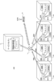
- FIG. 1 is a diagram schematically showing an overall configuration of a remote monitoring system 100 according to an embodiment.
- the remote monitoring system 100 includes a plurality of stores collectively referred to as a store 10, a communication network 14 such as the Internet or a mobile phone, and a service center 12 that collects and manages alarms transmitted from the store 10 via the communication network 14. .
- the store 10 is a food supermarket or a convenience store, and the store 10 is installed with devices such as a cooling device, an air conditioner, and a kitchen device.
- a controller is installed in the store 10. The controller detects an abnormality that has occurred in the device installed in the store 10 and transmits an alarm to the service center 12.
- the service center 12 is provided with an alarm management device 16 for collecting and managing alarms transmitted from the store 10.
- the warning management device 16 receives the warning, the warning management device 16 notifies the warning to the portable terminal 18 of the maintenance engineer in charge.
- the alarm management device 16 also includes a database 20 for accumulating and managing acquired alarms.
- the alarm management device 16 determines an expected time for completing a response for each assumed alarm, and is expected to receive a plurality of alarms transmitted from the store 10. Arrange them in the order of scheduled response completion times and notify maintenance personnel. Compared to arranging according to a fixed value such as the importance of an alarm, in the embodiment, the order is appropriately rearranged according to the progress of the alarm response, so that a plurality of alarms can be managed flexibly.
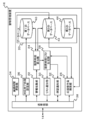
- FIG. 2 is a diagram schematically showing the internal configuration of the alarm management device 16 according to the embodiment.
- the alarm management device 16 includes a database 20, an alarm collection unit 22, a limit time calculation unit 24, a support maintenance staff search unit 26, a limit time list generation unit 28, a list notification unit 30, a confirmation notification unit 32, an actual time update unit 34, A correspondence completion time setting unit 36 and a transmission / reception unit 38 are included.
- the database 20 further includes a first database 40, a second database 42, and a third database 44.
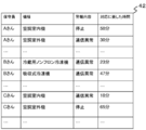
- the alarm collection unit 22 acquires the alarms transmitted from a plurality of devices installed in the store 10 and their occurrence times via the communication network 14 and the transmission / reception unit 38. As shown in FIG. 3, the alarm collection unit 22 is a list in which collected alarms are associated with stores where alarms are generated, devices and models where alarms are generated, alarm contents, and alarm generation times.
- the “current alarm table” is stored in a work memory (not shown).
- the communication network 14 and the transmission / reception unit 38 are simply assumed. It is described as “transmission” or “reception”.
- the first database 40, the second database 42, and the third database 44 in the database 20 will be described with reference to FIG. 4, FIG. 5, and FIG.
- FIG. 4 is a diagram schematically showing the structure of the first database 40 according to the embodiment.
- the first database 40 associates the store, the device and model in which the alarm has occurred, the content of the alarm, the response completion time expected by the maintenance personnel for the alarm, and information on who the maintenance engineer is.
- the “corresponding completion time request table”, which is a stored table, is stored.
- “contents of alarm” is information for specifying the state of the device that generated the alarm, for example, information such as device stoppage or communication abnormality.
- Equipment means individual devices such as “showcase near entrance” and “second-floor window air conditioner”, and “model” means, for example, a freezer open showcase or an air conditioner indoor unit. Means a category of such devices. Therefore, if the “device” can be specified, it is possible to specify in which store where the device is installed. Therefore, hereinafter, the device and model in which the alarm has occurred and the content of the alarm will be referred to as “alarm information”.
- FIG. 5 is a diagram schematically showing the structure of the second database 42 according to the embodiment.
- the second database 42 includes the model in which the alarm has occurred, the content of the alarm, information on who the maintenance staff should respond to the alarm, and the actual time corresponding to the alarm in the past for each maintenance staff.
- "Correspondence record table” which is a table in which is associated.
- FIG. 6 is a diagram schematically showing the structure of the third database 44 according to the embodiment.
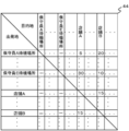
- the third database 44 stores the time required to move between a plurality of stores.
- the third database 44 also stores the time required to move from the maintenance staff standby location to each store.
- FIG. 6 shows that, for example, the time required to move from the standby location of the maintenance staff A to the store A is 5 minutes.
- the limit time calculation unit 24 refers to the “response completion time request table” stored in the first database 40 based on the alarm information collected by the alarm collection unit 22. Get the expected response completion time for that alarm.
- the limit time calculation unit 24 also refers to the “correspondence record table” stored in the second database 42 based on the alarm information collected by the alarm collection unit 22, and the maintenance personnel Acquire the actual time required for handling.
- the limit time calculation unit 24 is a time that will not be in time for the expected response completion time unless the response is started from the alarm generation time collected by the alarm collection unit 22 and the acquired response completion time and actual time.
- the limit time list generation unit 28 creates a limit time list, which is a list in which the corresponding start limit time calculated by the limit time calculation unit 24, the corresponding alarm, and the information of the maintenance staff in charge are arranged in association with each maintenance staff. .
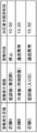
- FIG. 7 is a diagram illustrating an example of the limit time list created by the limit time list generation unit 28.
- the limit time list generation unit 28 may create the limit time list by arranging the corresponding start limit times in order from the earliest. For example, when there is an operator who operates the alarm management device 16 at the service center 12, it is advantageous in that the order of alarms to be handled can be grasped at a glance.
- the portable terminal 18 possessed by the maintenance engineer may rearrange the acquired limit time list in order of the corresponding start limit time. When the number of devices managed by the alarm management device 16 is large, it is advantageous in that the processing can be distributed.
- the list notification unit 30 transmits the limit time list created by the limit time list generation unit 28 to the portable terminal 18 held by each maintenance staff and notifies it.
- the maintenance engineer who receives the notification looks at the limit time list and starts to respond in order from the alarm with the earliest response start time limit.
- the support maintenance worker search unit 26 detects whether or not a corresponding maintenance worker is in time for a certain alarm by a corresponding start limit time. Specifically, the corresponding end time is estimated for each alarm based on the limit time list generated by the limit time list generation unit 28 and the actual time of maintenance personnel stored in the second database 42. It is detected whether the time is in time for one of the corresponding start limit times. More specifically, the support maintenance engineer search unit 26 determines whether or not a certain maintenance engineer is in time for the limit time by checking whether or not the following formula (2) is satisfied. May be.
- the “i-th store” should correspond to the store where the next device to be supported is installed, and the “i + 1-th store” should correspond after the “i-th store” has been handled. Represents a store where equipment is installed.
- “scheduled response start time for the i-th store” is calculated by the following equation (3).
- Expected start time of correspondence to the i-th store (scheduled start time of correspondence to the (i ⁇ 1) -th store + corresponding actual time + travel time from the (i ⁇ 1) -th store to the i-th store (3)
- the support maintenance staff member searching unit 26 refers to the second database 42 when the maintenance staff member in charge detects that the corresponding start person is not in time by the corresponding start time limit for a certain alarm. Search for maintenance personnel who are ready to start.
- the specific maintenance personnel search method is as follows. That is, the support maintenance worker search unit 26 acquires the current position of each maintenance worker, refers to the third database 44 based on the current position, and goes to the installation location of the device to which each maintenance worker has transmitted an alarm. Estimate the time. Based on the estimation result, a maintenance person who arrives in time by the corresponding start time limit is selected as a maintenance person in time.
- the support maintenance personnel search unit 26 selects the maintenance personnel with the shortest response record. Or you may select the maintenance person with the shortest movement time until it goes to the installation place of the apparatus which transmitted the alarm.
- each maintenance staff transmits a corresponding start time and a corresponding end time for a certain alarm to the alarm management device 16.
- the support maintenance worker search unit 26 acquires which store each maintenance worker is currently in based on the information of the corresponding start time and the corresponding end time transmitted from the maintenance personnel.
- the support maintenance staff search unit 26 acquires GPS information from the mobile terminal 18, and based on the information, The current position of the maintenance staff may be acquired.
- the limit time list generation unit 28 detects that the support maintenance worker search unit 26 detects that the corresponding maintenance start is not in time for the alarm with the support start time limit, and the support maintenance worker search unit 26 searches for the new support
- the limit time list is updated with the maintenance engineer as the maintenance engineer.
- the list notification unit 30 transmits the limit time list updated by the limit time list generation unit 28 to the maintenance staff posted in the limit time list for notification.
- the list notification unit 30 notifies the maintenance staff of the updated time limit list, it is possible to confirm an alarm that the user has to deal with. This makes it possible to quickly select a new maintenance person to replace the maintenance staff and notify it even if the warning response is not in time due to multiple warnings occurring within a short period of time, for example. It becomes.
- each maintenance staff transmits a corresponding start time and a corresponding end time for a certain alarm to the alarm management device 16.
- the confirmation notifying unit 32 periodically checks the all limit time list and checks the transmission of the corresponding start time from the maintenance staff in charge, so that the maintenance staff has not yet responded even if it is a predetermined time before the corresponding start limit time. Detect whether or not to start. As a result, when it is detected that the maintenance staff has not yet taken action, the confirmation notifying unit 32 transmits a notification to that effect to the maintenance staff.
- the “predetermined time” is, for example, a predetermined time for giving a notice in advance to give notice to a maintenance worker who has forgotten the response. This is the time required for traveling. Specifically, it may be determined adaptively from the relationship between the current position of the maintenance staff and the store where the alarm is generated, or may be a fixed value such as 30 minutes.
- the actual time update unit 34 receives the corresponding start time and the corresponding end time for each of the alarms corresponding to the maintenance staff transmitted from the maintenance staff.
- the actual time update unit 34 updates the actual time for the alarm in the second database 42 based on the actual time calculated from the received corresponding start time and corresponding end time. For example, the actual time stored in the second database is replaced with the latest actual time. Or you may replace with the average value of the past performance time so far, and the longest performance time which required the longest time until now.
- the response completion time setting unit 36 changes the setting of the response completion time expected for the alarm individually set for each device stored in the first database 40. This is performed by an operator of the service center 12 via a user interface (not shown) such as a keyboard or a mouse. Alternatively, a maintenance person who has heard a request from a customer at a place where each device is installed may transmit information from the mobile terminal 18 and change the information. By changing the response completion time depending on the newly installed equipment and the difference in the contents of the maintenance service set for each equipment, it becomes possible to provide a more detailed service with higher customer satisfaction.
- FIG. 2 shows a functional configuration for realizing the alarm management device 16 according to the embodiment, and other configurations are omitted.
- each element described as a functional block for performing various processes can be configured by a CPU (Central Processing Unit), main memory, and other LSI (Large Scale Integration) in hardware.
- CPU Central Processing Unit
- main memory main memory
- LSI Large Scale Integration
- software it is realized by a program loaded in the main memory. Therefore, it is understood by those skilled in the art that these functional blocks can be realized in various forms by hardware only, software only, or a combination thereof, and is not limited to any one.
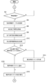
- FIG. 8 is the first half of a flowchart for explaining the flow of processing in the alarm management device 16 according to the embodiment. The processing in this flowchart starts when the alarm management device 16 is activated.
- the alarm collection unit 22 waits without performing any special processing while not receiving an alarm from each store 10 (N in S2). When an alarm is received (Y in S2), it is added to the “current alarm table” and updated (S4).
- the limit time list generation unit 28 acquires alarm information from the alarm collection unit 22, refers to the “response completion time request table” stored in the first database 40, and expects the response completion expected for the alarm. Time is acquired (S6).
- the limit time calculation unit 24 also refers to the “correspondence record table” stored in the second database 42 based on the alarm information collected by the alarm collection unit 22, and maintains the alarm to be handled.
- the member information is acquired (S8).
- the limit time list generation unit 28 determines the expected response completion time if the response is not started from the alarm occurrence time collected by the alarm collection unit 22, the response completion time, and the actual time of the maintenance staff in charge.
- the corresponding start limit time which is the time that is not in time, is calculated and acquired (S10).
- the limit time list generation unit 28 checks whether or not a limit time list is created for each maintenance person. If the limit time list does not exist (N in S12), the limit time list generation unit 28 creates a limit time list for the maintenance person (N). S14). When the limit time list exists (Y in S12), the corresponding start limit time calculated by the limit time list generation unit 28 is added to the limit time list (S16). In addition, the limit time list generation unit 28 rearranges the limit time list in order from the earliest corresponding start limit time (S18).
- FIG. 9 is the latter half of the flowchart for explaining the flow of processing in the alarm management device 16 according to the embodiment.
- the support maintenance worker search unit 26 secures the loop variable i in a work memory (not shown) and initializes the loop variable i with 1 (S20).
- the support maintenance worker search unit 26 acquires the limit time list from the limit time list generation unit 28 and confirms whether or not the i + 1-th alarm exists in the limit time list.
- the support maintenance staff search unit 26 detects whether the i + 1th corresponding start limit time is in time even if the ith alarm is dealt with. (S24).
- the support maintenance staff search unit 26 searches for support maintenance staff (S28), and causes the limit time list generation unit 28 to update the limit time list (S30).
- the support maintenance worker search unit 26 replaces the loop variable i with i + 1 and updates (S32), The process returns to S22 and continues.
- the list notification unit 30 notifies the maintenance personnel who have changed the limit time list and the updated limit. A time list is transmitted and notified (S34). Thereafter, the process returns to step S2 in FIG. 8, and the above processing is repeated.
- FIG. 10 is a flowchart for explaining the processing flow of the confirmation notifying unit 32 according to the embodiment.
- the confirmation notifying unit 32 acquires the current time from a timer (not shown) (S36).
- the confirmation notification unit 32 confirms whether or not the current time has passed until the first corresponding start limit time has passed, and if the predetermined time has elapsed (Y in S38), the confirmation notification unit 32 is subject to confirmation notification.
- An alarm is searched (S40). If the time has not elapsed (N in S38), the process returns to step S36.
- the confirmation notification unit 32 determines whether or not the searched notification has already been confirmed, and if the confirmation notification has been completed (Y in S42), the process returns to step S36.
- the confirmation notification unit 32 notifies the responsible maintenance staff of confirmation (S44).
- the confirmation notification unit 32 updates the limit time list by filling in a predetermined column (not shown) in the limit time list indicating that the confirmation notification has been completed (S46). After updating the limit time list, the process returns to step S36 to continue the above-described processing.
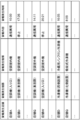
- FIG. 11 illustrates the alarm occurrence time and the corresponding timing at each maintenance staff.
- the vertical solid half-line indicates the expected response completion time expected for each alarm.
- a communication error is treated as a minor alarm, and a stop of the device is treated as an important alarm, and the maintenance staff is notified accordingly.
- an alarm may not occur in time for the response start time limit.
- the responsible maintenance staff A has already exceeded the response start limit time of the alarm generated at the store C when the response to the alarm generated at the store B is completed, and the response is delayed. As a result, the response of the alarm generated at the store C cannot be completed by the expected response completion scheduled time.
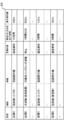
- FIG. 12 is a diagram illustrating a timetable corresponding to an alarm in the alarm management device 16 according to the embodiment.
- Each alarm in FIG. 12 is generated at the same timing as each alarm in FIG.
- the support maintenance worker search unit 26 detects that the maintenance start does not meet before the response start limit time of the alarm generated at the store C, and searches for the maintenance worker B as the support maintenance worker.
- the maintenance staff B responds to the alarm generated at the store C, so that the alarm can be completed by the expected response completion scheduled time.
- the maintenance staff A replaces the response of the alarm generated at the store I, which the maintenance staff B was scheduled to handle, so that the alarm generated at the store I is completed by the expected response completion time. Can do.
- the alarm management device 16 transmits the corresponding response start limit time for each alarm or the expected response completion scheduled time to the controller of the store where the alarm is generated, and the controller starts the response start limit time or expected. It is also possible to display the expected completion time of response. Thereby, it can respond efficiently by preparing in advance the system which receives a maintenance worker in the store where the alarm has occurred. Further, since the store side can grasp in advance the expected response completion time for the alarm, a sense of security can be obtained. Furthermore, since inquiries regarding the completion of the response from the store side can be reduced, the burden on the service center can be reduced.
- the alarm management device 16 As described above, according to the alarm management device 16 according to the embodiment, a plurality of alarms having different importance levels can be flexibly managed. In addition, even fewer maintenance personnel can respond efficiently than in the prior art.
- 10 stores, 12 service centers, 14 communication networks, 16 alarm management devices, 18 mobile terminals, 20 databases, 22 alarm collection units, 24 limit time calculation units, 26 support maintenance staff search units, 28 limit time list generation units, 30 lists Notification section, 32 confirmation notification section, 34 actual time update section, 36 corresponding completion time setting section, 38 transmission / reception section, 40 first database, 42 second database, 44 third database, 100 remote monitoring system.
Landscapes
- Business, Economics & Management (AREA)
- Physics & Mathematics (AREA)
- Human Resources & Organizations (AREA)
- Engineering & Computer Science (AREA)
- General Physics & Mathematics (AREA)
- Entrepreneurship & Innovation (AREA)
- Operations Research (AREA)
- Quality & Reliability (AREA)
- Strategic Management (AREA)
- Tourism & Hospitality (AREA)
- Marketing (AREA)
- General Business, Economics & Management (AREA)
- Economics (AREA)
- Theoretical Computer Science (AREA)
- Emergency Management (AREA)
- Management, Administration, Business Operations System, And Electronic Commerce (AREA)
- Alarm Systems (AREA)
- Telephonic Communication Services (AREA)
Abstract
【課題】重要度の異なる複数の警報を柔軟に管理できる装置を提供する。 【解決手段】警報収集部22は、複数の機器から送信される警報とその発生時刻とを取得する。第1のデータベース40は、警報の情報と、その警報について期待される対応完了時間とを関連づけて格納する。第2のデータベース42は、警報の情報と、その警報について保守員が過去に対応に要した実績時間とを関連づけて格納する。限界時刻算出部24は、警報収集部22が収集した警報の情報をもとに、第1のデータベース40を参照して対応完了時間、および第2のデータベース42を参照して実績時間を取得し、警報収集部22が収集した警報の発生時刻と取得した対応完了時間と実績時間とから、対応を開始しなければ期待される対応完了時間に間に合わなくなる時刻である対応着手限界時刻を算出する。
Description
本発明は警報管理装置に関する。
スーパーマーケットやコンビニエンスストア等の店舗に設置されている冷設機器、空調、厨房機器等の機器を管理するために、遠隔監視システムが導入されることがある。これら遠隔監視システムの機能のひとつとして、店舗内の冷設機器や空調に異常が発生したとき、担当の保守員に警報を通知する警報管理機能がある。
通常、警報には迅速に対応すべき重要な警報と、比較的軽微な警報とが混在する。そのため、警報を重要度で分類し、警報を重要度とともに担当の保守員に通知する技術が考案されている。軽微な警報が連続して発生した場合には警報通知を停止することで、重要な警報が軽微な警報に埋もれて見落とされることを抑制することも目的としている(特許文献1参照)。
上記の技術は、軽微な警報に優先して重要な警報を保守員に通知するため、場合によっては軽微な警報が長く放置されるということにもなりかねない。また一人の保守員では対応しきれないほど複数の警報が同時期に発生した場合に支障をきたす等、警報を保守員に通知する警報管理技術には改良の余地があると考えられる。
本発明はこうした状況に鑑みなされたものであり、その目的は、重要度の異なる複数の警報を柔軟に管理できる装置を提供することにある。
本発明のある態様は警報管理装置である。この装置は、複数の機器から送信される警報とその発生時刻とを取得する警報収集部と、警報の情報と、その警報について期待される対応完了時間とを関連づけて格納する第1のデータベースと、警報の情報と、その警報について保守員が過去に対応に要した実績時間とを関連づけて格納する第2のデータベースと、前記警報収集部が収集した警報の情報をもとに、前記第1のデータベースを参照して対応完了時間、および前記第2のデータベースを参照して実績時間を取得し、前記警報収集部が収集した警報の発生時刻と取得した対応完了時間と実績時間とから、対応を開始しなければ期待される対応完了予定時刻に間に合わなくなる時刻である対応着手限界時刻を算出する限界時刻算出部とを含む。
なお、以上の構成要素の任意の組み合わせ、本発明の表現を方法、システム、記録媒体、コンピュータプログラムなどの間で変換したものもまた、本発明の態様として有効である。
本発明によれば、重要度の異なる複数の警報を柔軟に管理できる装置を提供することができる。
図1は、実施の形態に係る遠隔監視システム100の全体構成を模式的に示した図である。遠隔監視システム100は、店舗10と総称する複数の店舗と、インターネットや携帯電話等による通信網14と、通信網14を介して店舗10から送信される警報を収集および管理するサービスセンター12を含む。
店舗10は、食品スーパーやコンビニエンスストアであり、店舗10には、冷設機器、空調、厨房機器等の機器が設置されている。これらの機器を統括的に制御するために、店舗10には、コントローラが設置されている。コントローラは、店舗10内に設置された機器に発生した異常を検出し、サービスセンター12に対して警報を送信する。
サービスセンター12には、店舗10から送信された警報を収集し管理するための警報管理装置16が設置されている。警報管理装置16は警報を受信すると、担当保守員の携帯端末18に警報を通知する。また、警報管理装置16は、取得した警報を蓄積したり管理したりするためのデータベース20を含む。
以上を前提として実施の形態の概要を述べる。実施の形態にかかる警報管理装置16は、想定される警報毎にその警報についての対応を完了するのに期待される時間を定めておき、店舗10から送信された複数の警報を、期待される対応完了予定時刻の順序に並べ替えて保守員に通知する。警報の重要度のように固定された値にしたがって並べることと比較して、実施の形態では警報対応の進行状況によって適宜順序が並べ替えられるため、複数の警報を柔軟に管理できる。
図2は、実施の形態に係る警報管理装置16の内部構成を模式的に示した図である。警報管理装置16は、データベース20、警報収集部22、限界時刻算出部24、応援保守員検索部26、限界時刻リスト生成部28、リスト通知部30、確認通知部32、実績時間更新部34、対応完了時間設定部36、および送受信部38を含む。またデータベース20は、第1のデータベース40、第2のデータベース42、および第3のデータベース44をさらに含む。
警報収集部22は、店舗10に設置された複数の機器から送信される警報とその発生時刻とを、通信網14および送受信部38を介して取得する。図3に示すように、警報収集部22は、収集した警報を、警報が発生した店舗と、警報が発生した機器および機種と、警報の内容と、警報の発生時刻とを関連づけたリストである「現在警報テーブル」を、ワークメモリ(図示せず)内に格納する。以下、本実施の形態において、警報管理装置16の各部が通信網14および送受信部38を介して警報管理装置16の外部と情報を送受信する場合、通信網14および送受信部38を前提として、単に「送信」または「受信」と記載する。
ここで、データベース20内の第1のデータベース40、第2のデータベース42、および第3のデータベース44について、図4、図5、および図6を参照して説明する。
図4は、実施の形態に係る第1のデータベース40の構造を模式的に示す図である。第1のデータベース40は、店舗と、警報が発生した機器および機種と、警報の内容と、その警報について保守員に期待される対応完了時間と、担当保守員が誰であるかの情報が関連づけられたテーブルである「対応完了時間要望テーブル」が格納されている。
ここで、「警報の内容」とは、その警報を発生した装置がどのような状態かを特定する情報であり、例えば装置の停止や通信異常といった情報である。また、「機器」とは、例えば「入り口付近ショーケース」や「2階窓際空調機」のように、個々の装置を意味し、「機種」とは、例えば冷凍オープンショーケースや空調室内機のような装置のカテゴリを意味する。したがって、「機器」が特定できれば、その装置がどの店舗のどこに設置されているかを特定することができる。そこで、以下、警報が発生した機器および機種とその警報の内容とをあわせて「警報の情報」ということにする。
図5は、実施の形態に係る第2のデータベース42の構造を模式的に示す図である。第2のデータベース42は、警報が発生した機種と、警報の内容と、その警報を対応すべき保守員が誰であるかの情報と、保守員毎に過去にその警報について対応した実績時間とが関連づけられたテーブルである「対応実績テーブル」が格納されている。
図6は、実施の形態に係る第3のデータベース44の構造を模式的に示す図である。第3のデータベース44は、複数の店舗間を移動するために要する時間を格納する。また、第3のデータベース44は、保守員の待機場所から各店舗まで移動するために要する時間も格納する。図6において、例えば保守員Aの待機場所から店舗Aまで移動するために要する時間は5分であることを示している。
図2の説明に戻り、限界時刻算出部24は、警報収集部22が収集した警報の情報をもとに、第1のデータベース40に格納されている「対応完了時間要望テーブル」を参照してその警報について期待される対応完了時間を取得する。限界時刻算出部24はまた、警報収集部22が収集した警報の情報をもとに、第2のデータベース42に格納されている「対応実績テーブル」を参照して、その警報について保守員が過去に対応に要した実績時間を取得する。その後限界時刻算出部24は、警報収集部22が収集した警報の発生時刻と、取得した対応完了時間および実績時間とから、対応を開始しなければ期待される対応完了予定時刻に間に合わなくなる時刻である対応着手限界時刻を、以下の式(1)を用いて算出する。
対応着手限界時刻=警報の発生時刻+対応完了時間-実績時間 (1)
対応着手限界時刻=警報の発生時刻+対応完了時間-実績時間 (1)
例えば、ある警報が13時に発生し、その警報について2時間以内、すなわち15時までに対応することが期待されているとする。保守員がその警報について過去に1時間で対応を完了した実績があるとするならば、13時+2時間-1時間=14時には、遅くとも対応に着手しなければならない。したがって、この場合の対応着手限界時刻は14時となる。
限界時刻リスト生成部28は、限界時刻算出部24が算出した対応着手限界時刻と該当する警報、および担当する保守員の情報を関連づけて並べたリストである限界時刻リストを保守員毎に作成する。図7は、限界時刻リスト生成部28が作成する限界時刻リストの一例を示す図である。ここで限界時刻リスト生成部28は、対応着手限界時刻を早い順に並べて限界時刻リストを作成してもよい。例えばサービスセンター12で警報管理装置16を操作するオペレータがいるような場合、対応すべき警報の順番を一見して把握できる点で有利である。また、担当保守員が所持する携帯端末18が、取得した限界時刻リストを、対応着手限界時刻の早い順に並べ替えてもよい。警報管理装置16が管理する機器の数が多い場合、処理を分散できる点で有利である。
リスト通知部30は、限界時刻リスト生成部28が作成した限界時刻リストを、各担当保守員が持つ携帯端末18に送信して通知する。通知を受けた担当保守員は、限界時刻リストを見て対応着手限界時刻の早い警報から順番に対応を着手する。
応援保守員検索部26は、ある警報について担当保守員が対応着手限界時刻までに対応着手が間に合うか否かを検出する。具体的には、限界時刻リスト生成部28が生成した限界時刻リストと第2のデータベース42に格納されている保守員の実績時間とをもとに、各警報について対応終了時刻を推定し、その時刻がいずれかの対応着手限界時刻に間に合うか否かを検出する。より具体的には、応援保守員検索部26は、ある保守員が限界時刻に間に合うか否かの判定は、以下の式(2)を満たすか否かを調べ、満たす場合は間に合うと判定してもよい。
i番目の店舗への対応開始予定時刻+対応実績時間+(i+1)番目の店舗への移動時間<(i+1)番目の対応着手限界時刻 (2)
ここで「i番目の店舗」は、次に対応すべき機器が設置されている店舗、「i+1番目の店舗」は、「i番目の店舗」における対応が終了した後、その次に対応すべき機器が設置されている店舗を表す。
i番目の店舗への対応開始予定時刻+対応実績時間+(i+1)番目の店舗への移動時間<(i+1)番目の対応着手限界時刻 (2)
ここで「i番目の店舗」は、次に対応すべき機器が設置されている店舗、「i+1番目の店舗」は、「i番目の店舗」における対応が終了した後、その次に対応すべき機器が設置されている店舗を表す。
また、「i番目の店舗への対応開始予定時刻」については、以下の式(3)で計算する。
i番目の店舗への対応開始予定時刻=(i-1)番目の店舗への対応開始予定時刻+対応実績時間+(i-1)番目の店舗からi番目の店舗への移動時間 (3)
ただし、i=1のとき、i番目の店舗への対応開始予定時刻=現在時刻+1番目の店舗への移動時間とする。
i番目の店舗への対応開始予定時刻=(i-1)番目の店舗への対応開始予定時刻+対応実績時間+(i-1)番目の店舗からi番目の店舗への移動時間 (3)
ただし、i=1のとき、i番目の店舗への対応開始予定時刻=現在時刻+1番目の店舗への移動時間とする。
応援保守員検索部26は、ある警報について担当保守員が対応着手限界時刻までに対応着手が間に合わないことを検出した場合、第2のデータベース42を参照して、その検出について対応着手限界時刻までに対応着手が間に合う保守員を検索する。具体的な保守員の検索方法を以下のとおりである。すなわち、応援保守員検索部26は、保守員それぞれの現在位置を取得し、その現在位置を元に第3のデータベース44を参照して各保守員が警報を送信した機器の設置場所に赴くまでの時間を推定する。推定結果をもとに、対応着手限界時刻までに到着が間に合う保守員を対応着手が間に合う保守員として選び出す。
応援保守員検索部26は、候補となる保守員が複数検出した場合には、応援保守員検索部26は、対応実績が最も短い保守員を選択する。あるいは、警報を送信した機器の設置場所に赴くまでの移動時間が最も短い保守員を選択してもよい。
ここで各保守員は、ある警報について対応着手時刻および対応終了時刻をそれぞれ警報管理装置16に送信するものとする。応援保守員検索部26は、保守員から送信された対応着手時刻および対応終了時刻の情報をもとに、各保守員が現在どの店舗にいるかを取得する。あるいは、各保守員が保持する携帯端末18にGPS(Global Positioning System)機能がある場合には、応援保守員検索部26は、携帯端末18からGPS情報を取得し、その情報をもとに各保守員の現在位置を取得してもよい。
限界時刻リスト生成部28は、応援保守員検索部26がある警報について担当保守員が対応着手限界時刻までに対応着手が間に合わないことを検出した場合、応援保守員検索部26が検索した新しい応援保守員を担当保守員として限界時刻リストを更新する。また、リスト通知部30は、限界時刻リスト生成部28が更新した限界時刻リストを、限界時刻リストに掲載されている保守員に送信して通知する。リスト通知部30が更新された限界時刻リストを保守員に通知することにより、自分が対応すべきことになった警報を確認することができる。これにより、例えば短期間のうちに複数の警報が発生することによって警報の対応が間に合わなくなったとしても、その保守員を代替する新たな保守員を迅速に選び出してその旨を通知することが可能となる。
上述したとおり、各保守員は、ある警報について対応着手時刻および対応終了時刻をそれぞれ警報管理装置16に送信する。確認通知部32は、全限界時刻リストを定期的に確認し、担当保守員から対応着手時刻の送信を調べることにより、対応着手限界時刻の所定時間前となっても、保守員による対応が未着手であるか否かを検出する。その結果、保守員による対応が未着手であることが検出された場合、確認通知部32は、その保守員にその旨を送信して通知する。
ここで「所定時間」とは、例えば、万が一対応を失念している保守員に気づきを与えるために前もって通知を行うために定められた時間であり、確認通知を受けた保守員が、対応に赴くまでに要する移動時間程度の時間である。具体的には保守員の現在位置と警報が発生した店舗との関係から適応的に定めてもよいし、30分等の固定値でもよい。
実績時間更新部34は、保守員から送信される、その保守員が対応する警報それぞれについてその対応着手時刻および対応終了時刻を受信する。実績時間更新部34は、受信した対応着手時刻および対応終了時刻から計算した実績時間をもとに、第2のデータベース42におけるその警報についての実績時間を更新する。更新の仕方は、例えば第2のデータベースに格納されている実績時間を最新の実績時間で置き換える。あるいは、これまでの実績時間の平均値や、これまでに最も長い時間を要した最長実績時間で置き換えてもよい。
対応完了時間設定部36は、第1のデータベース40に格納されている、機器毎に個々に設定された警報について期待される対応完了時間の設定を変更する。これは例えばキーボードやマウス等の図示しないユーザインターフェースを介して、サービスセンター12のオペレータによって行われる。あるいは、各機器の設置された場所において顧客からの要望を聞いた保守員が、携帯端末18から情報を送信して変更するようにしてもよい。新しく設置した機器や、機器毎に設定される保守サービスの内容の違いによって対応完了時間を変更することにより、より顧客満足の高いきめ細やかなサービスを提供することが可能となる。
図2は、実施の形態に係る警報管理装置16を実現するための機能構成を示しており、その他の構成は省略している。図2において、さまざまな処理を行う機能ブロックとして記載される各要素は、ハードウェア的には、CPU(Central Processing Unit)、メインメモリ、その他のLSI(Large Scale Integration)で構成することができ、ソフトウェア的には、メインメモリにロードされたプログラムなどによって実現される。したがって、これらの機能ブロックがハードウェアのみ、ソフトウェアのみ、またはそれらの組み合わせによっていろいろな形で実現できることは当業者には理解されるところであり、いずれかに限定されるものではない。
図8は、実施の形態に係る警報管理装置16内の処理の流れを説明するフローチャートの前半部分である。本フローチャートにおける処理は、警報管理装置16が起動すると開始する。
警報収集部22は、各店舗10から警報を受信しない間は(S2のN)、特段の処理をせずに待機する。警報を受信すると(S2のY)、「現在警報テーブル」に追加して更新する(S4)。
限界時刻リスト生成部28は、警報収集部22から警報の情報を取得して、第1のデータベース40に格納されている「対応完了時間要望テーブル」を参照してその警報について期待される対応完了時間を取得する(S6)。限界時刻算出部24はまた、警報収集部22が収集した警報の情報をもとに、第2のデータベース42に格納されている「対応実績テーブル」を参照して、その警報を対応すべき保守員の情報を取得する(S8)。
続いて限界時刻リスト生成部28は、警報収集部22が収集した警報の発生時刻と、対応完了時間および担当保守員の実績時間とから、対応を開始しなければ期待される対応完了予定時刻に間に合わなくなる時刻である対応着手限界時刻を算出して取得する(S10)。
限界時刻リスト生成部28は、各保守員別に限界時刻リストが作成されているか否かを調べ、限界時刻リストが存在しない場合(S12のN)、その保守員用の限界時刻リストを作成する(S14)。限界時刻リストが存在する場合(S12のY)、限界時刻リスト生成部28が算出した対応着手限界時刻を限界時刻リストに追加する(S16)。また、限界時刻リスト生成部28は、対応着手限界時刻の早い順に限界時刻リストを並べ替える(S18)
図9は、実施の形態に係る警報管理装置16内の処理の流れを説明するフローチャートの後半部分である。
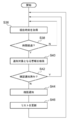
応援保守員検索部26は、図示しないワークメモリ内にループ変数iを確保して、ループ変数iを1で初期化する(S20)。応援保守員検索部26は、限界時刻リスト生成部28から限界時刻リストを取得し、限界時刻リストにi+1番目の警報が存在するか否かを確認する。限界時刻リストにi+1番目警報が存在する場合(S22のY)、応援保守員検索部26は、i番目の警報について対応しても、i+1番目の対応着手限界時刻に間に合うか否かを検出する(S24)。間に合わない場合(S26のN)、応援保守員検索部26は応援保守員を検索し(S28)、限界時刻リスト生成部28に限界時刻リストを更新させる(S30)。
間に合う場合(S26のY)か、あるいは限界時刻リスト生成部28に限界時刻リストを更新させた後、応援保守員検索部26はループ変数iをi+1に置き換えて更新し(S32)、上述のステップS22に戻って処理を継続する。ループ変数iを更新することによって限界時刻リストにi+1番目警報が存在しなくなった場合(S22のN)、リスト通知部30は、限界時刻リストに変更がある保守員にその旨および更新された限界時刻リストを送信して通知する(S34)。その後図8におけるステップS2に戻り、以上の処理を繰り返す。
図10は、実施の形態に係る確認通知部32の処理の流れを説明するフローチャートである。
確認通知部32は、図示しないタイマから現在時刻を取得する(S36)。確認通知部32は、現在時刻が1番目の対応着手限界時刻まで所定時間を切るほど経過したかどうかを確認し、所定時間が経過している場合(S38のY)、確認通知の対象となる警報を検索する(S40)。時間が経過していない場合(S38のN)はステップS36に戻る。
確認通知部32は、検索した通知が既に確認通知済みか否かを判断し、確認通知済みの場合(S42のY)、ステップS36に戻る。確認通知済みでない場合(S42のN)、確認通知部32は担当保守員に確認通知を行う(S44)。確認通知後、確認通知部32は、限界時刻リスト内の図示しない所定欄に確認通知済みの旨を記入して限界時刻リストを更新する(S46)。限界時刻リスト更新後ステップS36に戻って上述の処理を継続する。
以上の構成による警報管理装置16の動作の具体例を、以下図面を参照して説明する。なお、図11および図12中の「対応中」とは、移動時間と対応を行った時間との合計を示すものである。
まず、図11を参照して、従来技術における警報対応の進行を説明する。図11は、警報発生時刻と、各保守員における対応のタイミングとを図示したものである。図11において、縦の実線の半直線は、それぞれ各警報について期待される対応完了予定時刻を示している。
従来技術では、例えば通信異常は軽微な警報として、機器の停止は重要な警報とし扱われ、その旨が担当保守員に通知される。しかし、各警報についていつまでに対応を完了する必要があるかの情報は担当保守員通知されないため、場合によっては対応着手限界時刻に間に合わない警報が発生することもあり得る。図11の例では、担当保守員Aは店舗Bで発生した警報の対応を終了した時点で、既に店舗Cで発生した警報の対応着手限界時刻を越えており、対応に遅れが生じている。この結果、店舗Cで発生した警報の対応は、期待される対応完了予定時刻までに完了させることができていない。
図12は、実施の形態に係る警報管理装置16における警報対応のタイムテーブルを示す図である。図12における各警報は、図11における各警報と同じタイミングで発生している。応援保守員検索部26は、保守員Aが、店舗Cで発生した警報の対応着手限界時刻までに対応着手が間に合会わないことを検出し、応援保守員として保守員Bを検索する。店舗Cで発生した警報については保守員Bが対応することにより、その警報を期待される対応完了予定時刻までに完了させることが可能となる。また、保守員Bが担当する予定であった店舗Iで発生した警報の対応は保守員Aが代替することにより、店舗Iで発生した警報についても期待される対応完了予定時刻までに完了させることができる。
ここで、警報管理装置16は、各警報に対する対応着手限界時刻あるいは期待される対応完了予定時刻を、当該警報が発生している店舗のコントローラに送信し、当該コントローラに対応着手限界時刻あるいは期待される対応完了予定時刻を表示させることもできる。これにより、警報が発生している店舗において、保守員を受け入れる体制を予め整えることで、効率よく対応することができる。また、店舗側が警報に対する期待される対応完了予定時刻を事前に把握できるため、安心感を得ることができる。さらに、店舗側から対応完了に関する問い合わせを削減することができるため、サービスセンターの負担を軽減することができる。
以上説明したように実施の形態に係る警報管理装置16によれば、重要度の異なる複数の警報を柔軟に管理することができる。また、従来技術と比較して、少ない保守員でも、効率よく対応することができる。
以上、本発明を実施の形態をもとに説明した。この実施の形態は例示であり、それらの各構成要素や各処理プロセスの組み合わせにいろいろな変形例が可能なこと、またそうした変形例も本発明の範囲にあることは当業者に理解されるところである。
10 店舗、 12 サービスセンター、 14 通信網、 16 警報管理装置、 18 携帯端末、 20 データベース、 22 警報収集部、 24 限界時刻算出部、 26 応援保守員検索部、 28 限界時刻リスト生成部、 30 リスト通知部、 32 確認通知部、 34 実績時間更新部、 36 対応完了時間設定部、 38 送受信部、 40 第1のデータベース、 42 第2のデータベース、 44 第3のデータベース、 100 遠隔監視システム。
Claims (11)
- 複数の機器から送信される警報とその発生時刻とを取得する警報収集部と、
警報の情報と、その警報について期待される対応完了時間とを関連づけて格納する第1のデータベースと、
警報の情報と、その警報について保守員が過去に対応に要した実績時間とを関連づけて格納する第2のデータベースと、
前記警報収集部が収集した警報の情報をもとに、前記第1のデータベースを参照して対応完了時間、および前記第2のデータベースを参照して実績時間を取得し、前記警報収集部が収集した警報の発生時刻と取得した対応完了時間と実績時間とから、対応を開始しなければ期待される対応完了予定時刻に間に合わなくなる時刻である対応着手限界時刻を算出する限界時刻算出部とを含むことを特徴とする警報管理装置。 - 前記第2のデータベースは複数の保守員の情報を含み、かつ、保守員毎に過去に対応に要した時間を関連づけて格納するものであり、
前記第1のデータベースは警報の情報と、その警報について対応する保守員の情報も関連づけて格納するものであり、
本警報管理装置はさらに、ある警報について担当保守員が対応着手限界時刻までに対応着手が間に合わないことを検出した場合、前記第2のデータベースを参照して当該対応着手限界時刻までに対応着手が間に合う保守員を検索する応援保守員検索部を含むことを特徴とする請求項1に記載の警報管理装置。 - 複数の機器の設置場所間を移動するために要する時間を格納する第3のデータベースをさらに含み、
前記応援保守員検索部は、ある警報について担当保守員が対応着手限界時刻までに対応着手が間に合わないことを検出した場合、保守員それぞれの現在位置を取得し、当該現在位置を元に前記第3のデータベースを参照して各保守員が警報を送信した機器の設置場所に赴くまでの時間を推定することにより、当該対応着手限界時刻までに対応着手が間に合う保守員を検索することを特徴とする請求項2に記載の警報管理装置。 - 前記限界時刻算出部が算出した対応着手限界時刻と該当する警報、および担当する保守員の情報を関連づけて並べたリストを作成する限界時刻リスト生成部と、
前記限界時刻リスト生成部が作成したリストを担当保守員に通知するリスト通知部とをさらに含むことを特徴とする請求項2または3に記載の警報管理装置。 - 前記限界時刻リスト生成部は、対応着手限界時刻を早い順に並べたリストを作成するものであり、
前記リスト通知部は、前記限界時刻リスト生成部が作成した対応着手限界時刻を早い順に並べたリストを担当保守員に通知することを特徴とする請求項4に記載の警報管理装置。 - 前記限界時刻リスト生成部は、前記応援保守員検索部がある警報について担当保守員が対応着手限界時刻までに対応着手が間に合わないことを検出した場合、前記応援保守員検索部が検索した新しい保守員を担当保守員としてリストを更新し、
前記リスト通知部は、前記限界時刻リスト生成部が更新したリストを、リストに掲載されている保守員に通知することを特徴とする請求項4または5に記載の警報管理装置。 - 前記対応着手限界時刻の所定時間前に保守員による対応が未着手であることを検出し、当該保守員にその旨を通知する確認通知部をさらに含むことを特徴とする請求項1から6のいずれかに記載の警報管理装置。
- 対応する警報と、その対応開始時刻と対応終了時刻とを保守員から取得し、前記第2のデータベースにおける当該警報について対応に要した実績時間を更新する実績時間更新部をさらに含むことを特徴とする請求項1から7のいずれかに記載の警報管理装置。
- 前記第1のデータベースに格納されている、警報について期待される対応完了時間を、個々の機器毎に設定する対応完了時間設定部をさらに含むことを特徴とする請求項1から8のいずれかに記載の警報管理装置。
- 請求項1から9のいずれかに記載の警報管理装置から前記対応着手限界時刻及び/又は前記対応完了予定時刻を受信し、
当該対応着手限界時刻及び/又は前記対応完了予定時刻を表示することを特徴とする前記機器のコントローラ。 - 請求項4から9のいずれかに記載の警報管理装置の前記リスト通知部から前記リストを受信し、
当該リストを表示することを特徴とする前記保守員の携帯端末。
Applications Claiming Priority (2)
| Application Number | Priority Date | Filing Date | Title |
|---|---|---|---|
| JP2010-218822 | 2010-09-29 | ||
| JP2010218822A JP2013254230A (ja) | 2010-09-29 | 2010-09-29 | 警報管理装置 |
Publications (1)
| Publication Number | Publication Date |
|---|---|
| WO2012043293A1 true WO2012043293A1 (ja) | 2012-04-05 |
Family
ID=45892757
Family Applications (1)
| Application Number | Title | Priority Date | Filing Date |
|---|---|---|---|
| PCT/JP2011/071312 Ceased WO2012043293A1 (ja) | 2010-09-29 | 2011-09-20 | 警報管理装置 |
Country Status (2)
| Country | Link |
|---|---|
| JP (1) | JP2013254230A (ja) |
| WO (1) | WO2012043293A1 (ja) |
Citations (4)
| Publication number | Priority date | Publication date | Assignee | Title |
|---|---|---|---|---|
| JP2005070865A (ja) * | 2003-08-27 | 2005-03-17 | Seiko Epson Corp | 修理依頼スケジューリングシステム、修理依頼スケジューリング方法及び修理依頼スケジューリングプログラム |
| JP2006106861A (ja) * | 2004-09-30 | 2006-04-20 | Ricoh Co Ltd | 保守管理方法及び保守管理プログラム |
| JP2006277685A (ja) * | 2005-03-30 | 2006-10-12 | Fujitsu Ltd | 障害発生通知プログラム、および通知装置。 |
| JP2007048192A (ja) * | 2005-08-12 | 2007-02-22 | Hitachi Ltd | 保守計画支援システム |
-
2010
- 2010-09-29 JP JP2010218822A patent/JP2013254230A/ja active Pending
-
2011
- 2011-09-20 WO PCT/JP2011/071312 patent/WO2012043293A1/ja not_active Ceased
Patent Citations (4)
| Publication number | Priority date | Publication date | Assignee | Title |
|---|---|---|---|---|
| JP2005070865A (ja) * | 2003-08-27 | 2005-03-17 | Seiko Epson Corp | 修理依頼スケジューリングシステム、修理依頼スケジューリング方法及び修理依頼スケジューリングプログラム |
| JP2006106861A (ja) * | 2004-09-30 | 2006-04-20 | Ricoh Co Ltd | 保守管理方法及び保守管理プログラム |
| JP2006277685A (ja) * | 2005-03-30 | 2006-10-12 | Fujitsu Ltd | 障害発生通知プログラム、および通知装置。 |
| JP2007048192A (ja) * | 2005-08-12 | 2007-02-22 | Hitachi Ltd | 保守計画支援システム |
Also Published As
| Publication number | Publication date |
|---|---|
| JP2013254230A (ja) | 2013-12-19 |
Similar Documents
| Publication | Publication Date | Title |
|---|---|---|
| EP3662427B1 (en) | System and method for managing an industrial equipment system | |
| US9864417B2 (en) | Server rack for improved data center management | |
| JP2016173782A (ja) | 故障予測システム、故障予測方法、故障予測装置、学習装置、故障予測プログラム及び学習プログラム | |
| US12425894B2 (en) | Predicting future wireless coverage based on weather | |
| JP5903121B2 (ja) | 災害復旧支援システムおよび災害復旧支援プログラム | |
| US20240205642A1 (en) | Synchronization/resynchronization of data assets based on entering a wireless dead zone geofence | |
| US20240205707A1 (en) | Synchronization/resynchronization of data assets based on wireless dead zone geofence changes | |
| JP4744856B2 (ja) | 医用機器管理装置及び医用機器の管理方法 | |
| US12501278B2 (en) | Generating wireless coverage maps | |
| WO2018005684A1 (en) | Systems and methods for tracking items | |
| JPH0749712A (ja) | 設備保全管理装置 | |
| JP2004127044A (ja) | 処理人員割当方法 | |
| JPWO2016199251A1 (ja) | 設備保守管理システム、設備保守装置及びプログラム | |
| US11915178B2 (en) | Cascading notification system | |
| JP2014199618A (ja) | 故障監視システム | |
| JP6402468B2 (ja) | 部品交換サービスシステム | |
| JP6161990B2 (ja) | 外部インタフェース装置制御システム及び外部インタフェース装置制御方法 | |
| JP5360090B2 (ja) | 多店舗型施設の設備運用システムとその処理方法とプログラム | |
| JP2013254230A (ja) | 警報管理装置 | |
| CN106407069B (zh) | 用于管理能量管理系统中的数据库的设备和方法 | |
| WO2024136945A1 (en) | Generating and using wireless coverage maps | |
| JP5899448B2 (ja) | データ通信システム | |
| JP2019128754A (ja) | 不具合対応システム | |
| JP6833669B2 (ja) | 設備監視システム | |
| JP4359572B2 (ja) | 状態管理装置及び方法 |
Legal Events
| Date | Code | Title | Description |
|---|---|---|---|
| 121 | Ep: the epo has been informed by wipo that ep was designated in this application |
Ref document number: 11828850 Country of ref document: EP Kind code of ref document: A1 |
|
| NENP | Non-entry into the national phase |
Ref country code: DE |
|
| 122 | Ep: pct application non-entry in european phase |
Ref document number: 11828850 Country of ref document: EP Kind code of ref document: A1 |
|
| NENP | Non-entry into the national phase |
Ref country code: JP |