WO2012042880A1 - Biomolecule detection device and biomolecule detection method - Google Patents
Biomolecule detection device and biomolecule detection method Download PDFInfo
- Publication number
- WO2012042880A1 WO2012042880A1 PCT/JP2011/005487 JP2011005487W WO2012042880A1 WO 2012042880 A1 WO2012042880 A1 WO 2012042880A1 JP 2011005487 W JP2011005487 W JP 2011005487W WO 2012042880 A1 WO2012042880 A1 WO 2012042880A1
- Authority
- WO
- WIPO (PCT)
- Prior art keywords
- light
- orientation control
- fluorescence
- molecule
- orientation
- Prior art date
Links
- 238000001514 detection method Methods 0.000 title claims abstract description 163
- 239000013076 target substance Substances 0.000 claims abstract description 54
- 230000001360 synchronised effect Effects 0.000 claims abstract description 17
- 230000005284 excitation Effects 0.000 claims description 136
- 230000007704 transition Effects 0.000 claims description 57
- 239000000126 substance Substances 0.000 claims description 18
- 230000001678 irradiating effect Effects 0.000 claims description 6
- 238000000605 extraction Methods 0.000 claims description 5
- 230000027455 binding Effects 0.000 abstract description 184
- 238000005259 measurement Methods 0.000 abstract description 43
- 238000005286 illumination Methods 0.000 abstract 1
- 239000003153 chemical reaction reagent Substances 0.000 description 103
- 238000010586 diagram Methods 0.000 description 46
- 239000000427 antigen Substances 0.000 description 42
- 102000036639 antigens Human genes 0.000 description 42
- 108091007433 antigens Proteins 0.000 description 42
- 230000010287 polarization Effects 0.000 description 38
- 238000006243 chemical reaction Methods 0.000 description 37
- 230000008859 change Effects 0.000 description 21
- 238000000034 method Methods 0.000 description 20
- 230000003287 optical effect Effects 0.000 description 18
- 230000005653 Brownian motion process Effects 0.000 description 16
- 238000005537 brownian motion Methods 0.000 description 16
- KZMAWJRXKGLWGS-UHFFFAOYSA-N 2-chloro-n-[4-(4-methoxyphenyl)-1,3-thiazol-2-yl]-n-(3-methoxypropyl)acetamide Chemical compound S1C(N(C(=O)CCl)CCCOC)=NC(C=2C=CC(OC)=CC=2)=C1 KZMAWJRXKGLWGS-UHFFFAOYSA-N 0.000 description 10
- 230000007423 decrease Effects 0.000 description 10
- 238000001506 fluorescence spectroscopy Methods 0.000 description 10
- 102000039446 nucleic acids Human genes 0.000 description 10
- 108020004707 nucleic acids Proteins 0.000 description 10
- 150000007523 nucleic acids Chemical class 0.000 description 10
- 239000000523 sample Substances 0.000 description 9
- IGAZHQIYONOHQN-UHFFFAOYSA-N Alexa Fluor 555 Chemical compound C=12C=CC(=N)C(S(O)(=O)=O)=C2OC2=C(S(O)(=O)=O)C(N)=CC=C2C=1C1=CC=C(C(O)=O)C=C1C(O)=O IGAZHQIYONOHQN-UHFFFAOYSA-N 0.000 description 6
- 239000012109 Alexa Fluor 568 Substances 0.000 description 6
- 239000008280 blood Substances 0.000 description 6
- 210000004369 blood Anatomy 0.000 description 6
- 238000002875 fluorescence polarization Methods 0.000 description 6
- 238000005070 sampling Methods 0.000 description 6
- 229920006395 saturated elastomer Polymers 0.000 description 6
- 239000007790 solid phase Substances 0.000 description 6
- 239000002904 solvent Substances 0.000 description 5
- 102000007066 Prostate-Specific Antigen Human genes 0.000 description 4
- 108010072866 Prostate-Specific Antigen Proteins 0.000 description 4
- 238000004364 calculation method Methods 0.000 description 4
- 238000011088 calibration curve Methods 0.000 description 4
- 239000007788 liquid Substances 0.000 description 4
- 238000002360 preparation method Methods 0.000 description 4
- 230000003321 amplification Effects 0.000 description 3
- 230000000694 effects Effects 0.000 description 3
- 238000003018 immunoassay Methods 0.000 description 3
- 239000007791 liquid phase Substances 0.000 description 3
- 239000003068 molecular probe Substances 0.000 description 3
- 238000003199 nucleic acid amplification method Methods 0.000 description 3
- 230000000737 periodic effect Effects 0.000 description 3
- 230000002093 peripheral effect Effects 0.000 description 3
- 238000003127 radioimmunoassay Methods 0.000 description 3
- 206010041823 squamous cell carcinoma Diseases 0.000 description 3
- 241000894006 Bacteria Species 0.000 description 2
- 102000004856 Lectins Human genes 0.000 description 2
- 108090001090 Lectins Proteins 0.000 description 2
- 108091005804 Peptidases Proteins 0.000 description 2
- 239000004365 Protease Substances 0.000 description 2
- 102100037486 Reverse transcriptase/ribonuclease H Human genes 0.000 description 2
- 241000700605 Viruses Species 0.000 description 2
- 230000008901 benefit Effects 0.000 description 2
- 210000001124 body fluid Anatomy 0.000 description 2
- 238000001917 fluorescence detection Methods 0.000 description 2
- 239000002523 lectin Substances 0.000 description 2
- 239000003446 ligand Substances 0.000 description 2
- 230000005389 magnetism Effects 0.000 description 2
- 102000044158 nucleic acid binding protein Human genes 0.000 description 2
- 108700020942 nucleic acid binding protein Proteins 0.000 description 2
- 239000012071 phase Substances 0.000 description 2
- 102000004169 proteins and genes Human genes 0.000 description 2
- 238000011002 quantification Methods 0.000 description 2
- 230000035945 sensitivity Effects 0.000 description 2
- 238000000926 separation method Methods 0.000 description 2
- 235000000346 sugar Nutrition 0.000 description 2
- 210000002700 urine Anatomy 0.000 description 2
- 108091005461 Nucleic proteins Proteins 0.000 description 1
- 206010036790 Productive cough Diseases 0.000 description 1
- 238000002835 absorbance Methods 0.000 description 1
- 238000004458 analytical method Methods 0.000 description 1
- 238000013459 approach Methods 0.000 description 1
- 239000010839 body fluid Substances 0.000 description 1
- 238000013461 design Methods 0.000 description 1
- 238000003745 diagnosis Methods 0.000 description 1
- 239000006185 dispersion Substances 0.000 description 1
- 239000000975 dye Substances 0.000 description 1
- 230000005684 electric field Effects 0.000 description 1
- 238000010291 electrical method Methods 0.000 description 1
- 230000005281 excited state Effects 0.000 description 1
- 230000005283 ground state Effects 0.000 description 1
- 239000012456 homogeneous solution Substances 0.000 description 1
- 238000007689 inspection Methods 0.000 description 1
- 230000003993 interaction Effects 0.000 description 1
- 239000004973 liquid crystal related substance Substances 0.000 description 1
- 230000007246 mechanism Effects 0.000 description 1
- 238000012986 modification Methods 0.000 description 1
- 230000004048 modification Effects 0.000 description 1
- 230000009149 molecular binding Effects 0.000 description 1
- 239000010813 municipal solid waste Substances 0.000 description 1
- 230000008569 process Effects 0.000 description 1
- 108090000623 proteins and genes Proteins 0.000 description 1
- 230000005855 radiation Effects 0.000 description 1
- 239000000941 radioactive substance Substances 0.000 description 1
- 230000004044 response Effects 0.000 description 1
- 210000003802 sputum Anatomy 0.000 description 1
- 208000024794 sputum Diseases 0.000 description 1
- 108010088201 squamous cell carcinoma-related antigen Proteins 0.000 description 1
- 150000008163 sugars Chemical class 0.000 description 1
- 210000004243 sweat Anatomy 0.000 description 1
Images


Classifications
-
- G—PHYSICS
- G01—MEASURING; TESTING
- G01N—INVESTIGATING OR ANALYSING MATERIALS BY DETERMINING THEIR CHEMICAL OR PHYSICAL PROPERTIES
- G01N21/00—Investigating or analysing materials by the use of optical means, i.e. using sub-millimetre waves, infrared, visible or ultraviolet light
- G01N21/62—Systems in which the material investigated is excited whereby it emits light or causes a change in wavelength of the incident light
- G01N21/63—Systems in which the material investigated is excited whereby it emits light or causes a change in wavelength of the incident light optically excited
- G01N21/64—Fluorescence; Phosphorescence
- G01N21/6486—Measuring fluorescence of biological material, e.g. DNA, RNA, cells
-
- G—PHYSICS
- G01—MEASURING; TESTING
- G01N—INVESTIGATING OR ANALYSING MATERIALS BY DETERMINING THEIR CHEMICAL OR PHYSICAL PROPERTIES
- G01N21/00—Investigating or analysing materials by the use of optical means, i.e. using sub-millimetre waves, infrared, visible or ultraviolet light
- G01N21/62—Systems in which the material investigated is excited whereby it emits light or causes a change in wavelength of the incident light
- G01N21/63—Systems in which the material investigated is excited whereby it emits light or causes a change in wavelength of the incident light optically excited
- G01N21/64—Fluorescence; Phosphorescence
- G01N21/6445—Measuring fluorescence polarisation
-
- G—PHYSICS
- G01—MEASURING; TESTING
- G01N—INVESTIGATING OR ANALYSING MATERIALS BY DETERMINING THEIR CHEMICAL OR PHYSICAL PROPERTIES
- G01N21/00—Investigating or analysing materials by the use of optical means, i.e. using sub-millimetre waves, infrared, visible or ultraviolet light
- G01N21/62—Systems in which the material investigated is excited whereby it emits light or causes a change in wavelength of the incident light
- G01N21/63—Systems in which the material investigated is excited whereby it emits light or causes a change in wavelength of the incident light optically excited
- G01N21/64—Fluorescence; Phosphorescence
- G01N21/6428—Measuring fluorescence of fluorescent products of reactions or of fluorochrome labelled reactive substances, e.g. measuring quenching effects, using measuring "optrodes"
-
- G—PHYSICS
- G01—MEASURING; TESTING
- G01N—INVESTIGATING OR ANALYSING MATERIALS BY DETERMINING THEIR CHEMICAL OR PHYSICAL PROPERTIES
- G01N33/00—Investigating or analysing materials by specific methods not covered by groups G01N1/00 - G01N31/00
- G01N33/48—Biological material, e.g. blood, urine; Haemocytometers
- G01N33/50—Chemical analysis of biological material, e.g. blood, urine; Testing involving biospecific ligand binding methods; Immunological testing
- G01N33/53—Immunoassay; Biospecific binding assay; Materials therefor
- G01N33/543—Immunoassay; Biospecific binding assay; Materials therefor with an insoluble carrier for immobilising immunochemicals
- G01N33/54366—Apparatus specially adapted for solid-phase testing
- G01N33/54373—Apparatus specially adapted for solid-phase testing involving physiochemical end-point determination, e.g. wave-guides, FETS, gratings
-
- G—PHYSICS
- G01—MEASURING; TESTING
- G01N—INVESTIGATING OR ANALYSING MATERIALS BY DETERMINING THEIR CHEMICAL OR PHYSICAL PROPERTIES
- G01N21/00—Investigating or analysing materials by the use of optical means, i.e. using sub-millimetre waves, infrared, visible or ultraviolet light
- G01N21/62—Systems in which the material investigated is excited whereby it emits light or causes a change in wavelength of the incident light
- G01N21/63—Systems in which the material investigated is excited whereby it emits light or causes a change in wavelength of the incident light optically excited
- G01N21/64—Fluorescence; Phosphorescence
- G01N21/6428—Measuring fluorescence of fluorescent products of reactions or of fluorochrome labelled reactive substances, e.g. measuring quenching effects, using measuring "optrodes"
- G01N2021/6439—Measuring fluorescence of fluorescent products of reactions or of fluorochrome labelled reactive substances, e.g. measuring quenching effects, using measuring "optrodes" with indicators, stains, dyes, tags, labels, marks
Definitions
- the present invention relates to a technique for detecting a detection target substance in a solution, and more particularly to a biomolecule detection apparatus and a biomolecule detection method capable of detecting biomolecules, viruses, nucleic acids, proteins, bacteria, and the like in a specimen. .
- the biomolecule detection method is a method that selectively detects only a substance to be detected from a bodily fluid having a plurality of components such as blood, urine, and sweat by high selectivity using a specific reaction such as an antigen-antibody reaction. is there.
- a biomolecule detection method is widely used particularly for detection, inspection, quantification and analysis of biomolecules such as viruses, nucleic acids, proteins and bacteria.
- Radioimmunoassay has been put to practical use as a biomolecule detection method.
- an antigen or antibody labeled with an isotope is used to detect the presence or absence of an antibody or antigen that specifically binds to the antigen or antibody.
- the radioimmunoassay quantifies a detection target substance such as an antibody or an antigen by measuring the radiation dose of an isotope, and can perform highly sensitive measurement.
- Fluorescence immunoassay is a biomolecule detection method that does not use radioactive substances.
- the antibody is immobilized on the reaction layer in advance (the reaction layer on which the antibody is immobilized is referred to as a solid phase), and the solution to be measured and the antibody labeled with the fluorescent molecule are passed through the reaction layer.
- An apparatus for measuring the concentration of an antigen specifically bound to an antibody by measuring the nearby fluorescence is known (see, for example, Patent Document 1).
- the fluorescence immunoassay using a solid phase has a problem that it takes a high cost to prepare the solid phase.
- a method for detecting a biomolecule in a liquid without using a solid phase that is, using only the liquid phase
- the fluorescence polarization method is a method for detecting a change in the value of the degree of fluorescence polarization based on a change in Brownian motion, which occurs when another molecule binds to a fluorescently labeled molecule and the size of the molecule changes.
- a biomolecule detection method using a fluorescence polarization method is known as a simple and quick detection method for a substance to be detected in a specimen (see, for example, Patent Document 2).
- the conventional fluorescence polarization method has a problem in that there is a limit in measurement sensitivity because it uses a change in Brownian motion, which is a random motion.
- the fluorescence lifetime needs to be long enough to be affected by the change in Brownian motion.
- the measurement results obtained by the method of Patent Document 2 may vary.
- the present invention has been made in view of the above circumstances, and an object thereof is to provide a biomolecule detection apparatus and a biomolecule detection method capable of highly sensitive measurement.
- a biomolecule detection apparatus comprises: Fluorescence generated from a first complex having a substance that specifically binds to the detection target substance and a fluorescent molecule, and fluorescence generated from a second complex in which the first complex and the detection target substance are bound
- Fluorescence generated from a first complex having a substance that specifically binds to the detection target substance and a fluorescent molecule, and fluorescence generated from a second complex in which the first complex and the detection target substance are bound Is a biomolecule detection device that detects or quantifies a detection target substance present in a solution, A light source that emits excitation light having a linearly polarized component in a specific direction to excite fluorescent molecules; A light receiving portion for detecting fluorescence generated from the fluorescent molecules; An orientation control means for periodically switching and orienting the second complex in the solution; Synchronous component extraction means for extracting a component synchronized with the period in which the second complex is oriented among the fluorescence detected by the light receiving unit; And a calculation unit that detects or quantifies the detection target
- the orientation control means includes a first direction in which the transition moment of the fluorescent molecule included in the second complex is parallel to the vibration direction of the linearly polarized component of the excitation light, and The transition moment is preferably switched and oriented in the second direction perpendicular to the vibration direction.
- the cycle of switching and orienting the second complex includes the molecular weight or volume of the detection target substance, the molecular weight of the substance that specifically binds to the detection target substance, and the fluorescent molecule or It is preferably determined based on the volume and the strength of orientation control by the orientation control means.
- the orientation control means preferably includes an orientation control light source that orients the second complex by irradiating light having a wavelength different from that of the excitation light.
- the orientation control light source irradiates the solution with the light having a wavelength different from that of the excitation light from a plurality of positions.
- the orientation control means includes an orientation control light source
- the orientation control light source irradiates the light having a wavelength different from that of the excitation light in the direction of exiting from the plane of the solution holding portion through the solution, and the excitation light is emitted at the interface between the solution and the plane. It is preferable to focus on the light having different wavelengths.
- the light receiving unit includes a spectroscopic unit that splits light.
- the spectroscopic means is a plurality of filters having different characteristics, and the light receiving unit switches the plurality of filters in accordance with the wavelength of fluorescence.
- the biomolecule detection method includes: Fluorescence generated from a first complex having a substance that specifically binds to the detection target substance and a fluorescent molecule, and fluorescence generated from a second complex in which the first complex and the detection target substance are bound Is a biomolecule detection method for detecting or quantifying a detection target substance present in a solution, Irradiating excitation light having a linearly polarized light component in a specific direction and exciting fluorescent molecules; Periodically switching and orienting the second complex in solution; Detecting fluorescence generated from fluorescent molecules; Extracting a component synchronized with the period in which the second complex is orientated from the detected fluorescence; Detecting or quantifying the detection target substance based on the extracted component.
- biomolecule detection can be performed.
- FIG. 3 is a schematic diagram for explaining an outline of an antigen-antibody reaction of the biomolecule detection apparatus according to the first embodiment.
- FIG. 3 is a schematic diagram for explaining an outline of an antigen-antibody reaction of the biomolecule detection apparatus according to the first embodiment. It is the model showing the case where the vibration direction of excitation light and the transition moment of a fluorescent molecule are mutually parallel. It is a schematic diagram showing the case where the vibration direction of excitation light and the transition moment of fluorescent molecules are perpendicular to each other.
- FIG. 5 is a schematic diagram showing free molecules (fluorescent molecules and antibodies to which no antigen is bound).
- FIG. 3 is a schematic diagram showing binding molecules (fluorescent molecules and antibodies bound by an antigen).
- FIG. 1 is an external perspective view of a biomolecule detection apparatus according to Embodiment 1.
- FIG. 2 is an external perspective view of the biomolecule detection device according to Embodiment 1 with an opening / closing part opened.
- FIG. It is a block diagram which shows the main structures of a biomolecule detection apparatus. It is the schematic diagram which looked at switching of the irradiation direction of the orientation control light irradiated from the light source part for orientation control from the upper surface. It is the schematic diagram showing the irradiation direction with orientation control light, and the orientation direction of a binding molecule. It is the schematic diagram showing the irradiation direction of the orientation control light orthogonal to the irradiation direction in FIG. 7A, and the orientation direction of a binding molecule.
- FIG. 4 is a schematic diagram illustrating a detailed configuration of a light receiving unit in the biomolecule detection apparatus according to Embodiment 1.
- FIG. It is the figure which represented typically the flow from sample preparation to disposal.
- 4 is a graph showing an orientation control signal and PD output in the biomolecule detection apparatus according to Embodiment 1.
- 3 is a graph showing a lock-in amplifier output in the biomolecule detection apparatus according to the first embodiment.
- 6 is a schematic diagram for explaining an outline of an antigen-antibody reaction of the biomolecule detection apparatus according to Embodiment 2.
- FIG. 6 is a schematic diagram for explaining an outline of an antigen-antibody reaction of the biomolecule detection apparatus according to Embodiment 2.
- FIG. 6 is a block diagram illustrating a main configuration of a biomolecule detection apparatus according to Embodiment 2.
- 6 is a schematic diagram illustrating a detailed configuration of a light receiving unit in a biomolecule detection apparatus according to Embodiment 2.
- FIG. 10 is a graph showing PD output for one detection target substance in the second embodiment.
- 6 is a graph showing a PD output for the other detection target substance in the second embodiment. It is a conceptual diagram showing the relationship between the direction of the transition moment of a fluorescent molecule and the vibration direction of randomly polarized excitation light when the orientation control light is irradiated from one side.
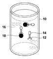
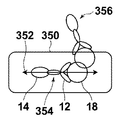
- FIGS. 1A and 1B are schematic diagrams showing an outline of an antigen-antibody reaction in the biomolecule detection apparatus according to Embodiment 1 of the present invention.
- the antigen-antibody reaction in the liquid will be described with reference to FIGS. 1A and 1B.
- one type of antibody is used and one type of antigen is detected in a homogeneous solution.
- the dried antibody 12 is placed in the cylindrical reagent cup 10.
- the antibody 12 is labeled with a fluorescent molecule 14.
- the specimen is plasma 16 separated from whole blood.
- the plasma 16 is dispensed into the reagent cup 10 and stirred, if an antigen 18 that specifically binds to the antibody 12 is present in the plasma 16, an antigen-antibody reaction occurs between the antibody 12 and the antigen 18. As shown in 1B, antibody 12 and antigen 18 are specifically bound and present in the plasma solution.
- plasma 16 separated from whole blood is used as a specimen, and PSA (Prostate Specific Antigen) is detected as an antigen 18 that is a detection target substance, and a substance that specifically binds to the detection target substance.
- PSA Prostate Specific Antigen
- a case where an anti-PSA antibody is used as an antibody 12 will be described.
- the fluorescent molecule 14 Alexa Fluor 568 (trade name of Molecular Probes) was used. Alexa Fluor 568 has a peak at a wavelength of about 610 nm and emits fluorescence having a wavelength of about 550 nm to 700 nm.
- the antibody 12 Since the antibody 12 is contained in a sufficiently large amount with respect to the antigen 18, a part of the antibody 12 remains in the plasma 16 without undergoing an antigen-antibody reaction.
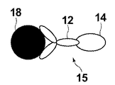
- the complex of the antibody 12 and the antigen 18 and the fluorescent molecule 14 bound by the antigen-antibody reaction is called a binding molecule
- the complex of the antibody 12 and the fluorescent molecule 14 floating in the liquid without the antigen-antibody reaction is called a free molecule.
- Binding molecules and free molecules are mixed in plasma 16.
- components other than the antigen 18 exist in the plasma 16
- components other than the antigen 18 are omitted in FIGS. 1A and 1B for the sake of simplicity.
- the biomolecule detection apparatus irradiates excitation light to a solution in which free molecules and binding molecules are mixed due to the liquid phase, and receives fluorescence generated from the fluorescent molecules 14. Then, the antigen 18 is detected and quantified. Therefore, it is desirable to detect only the fluorescence generated from the binding molecule containing the antigen 18.
- fluorescence is also generated from the fluorescent molecules 14 associated with the free molecules. This fluorescence becomes an unnecessary component in relation to the fluorescence generated from the fluorescent molecule 14 accompanying the binding molecule.
- the biomolecule detection apparatus detects fluorescence while switching the orientation of the binding molecule with light, and binds from the total fluorescence data based on the change in fluorescence intensity associated with the orientation change. The contribution of fluorescence generated from the fluorescent molecule 14 accompanying the molecule is calculated.
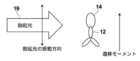
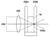
- FIG. 2A is a schematic diagram illustrating a case where the vibration direction of the excitation light 19 and the direction of the transition moment of the fluorescent molecule 14 are parallel to each other
- FIG. 2B illustrates the vibration direction of the excitation light 19 and the direction of the transition moment of the fluorescent molecule 14. It is a schematic diagram showing the case where is perpendicular.
- the longitudinal direction of the fluorescent molecule 14 (the long axis direction of the fluorescent molecule 14 indicated by an ellipse) and the direction of the transition moment are parallel to each other. That is, FIGS.
- FIGS. 2A and 2B are diagrams depicting a case where the direction of the fluorescent molecule 14 (the long axis direction of the fluorescent molecule 14 indicated by an ellipse) and the direction of the transition moment coincide.
- the “vibration direction” of light means the vibration direction of an electric field, and has the same meaning as the polarization direction when light is polarized.
- Fluorescent molecules 14 transition to an excited state when absorbing light energy, and emit fluorescence in the process of returning to the ground state.
- the fluorescent molecule 14 when the fluorescent molecule 14 is excited with linearly polarized excitation light, the fluorescent molecule 14 emits fluorescence polarized in the same direction as the vibration direction of the excitation light.
- the degree of polarization of the fluorescence generated from the fluorescent molecule 14 depends on the rotational speed of the fluorescent molecule 14. In other words, if the fluorescent molecule 14 does not rotate, the fluorescent molecule 14 emits fluorescence polarized in the same direction as the vibration direction of the excitation light. The faster the fluorescent molecule 14 rotates, the more the fluorescent molecule 14 is generated. The degree of polarization of fluorescent light is small.
- the fluorescent molecule 14 When the fluorescent molecule 14 is excited, a vector in the fluorescent molecule 14 called a transition moment determined by the molecular structure of the fluorescent molecule 14 interacts with the excitation light 19.
- the transition moment has a specific direction in the fluorescent molecule 14, and the relationship between the direction of the transition moment and the vibration direction of the excitation light 19 determines the excitation efficiency of the fluorescent molecule 14.
- the fluorescent molecule 14 selectively absorbs light that vibrates in a direction parallel to the direction of the transition moment. Therefore, as shown in FIGS. 2A and 2B, when the excitation light 19 travels from left to right while oscillating up and down on the paper surface and hits the fluorescent molecule 14, the vibration direction of the linearly polarized excitation light 19 is the transition of the fluorescent molecule 14.
- the excitation efficiency is highest when parallel to the direction of the moment (FIG. 2A), and the excitation efficiency decreases as the angle between the vibration direction of the linearly polarized excitation light 19 and the direction of the transition moment of the fluorescent molecule 14 increases.
- the vibration direction of the linearly polarized excitation light 19 is orthogonal to the direction of the transition moment of the fluorescent molecule 14 (FIG. 2B)
- the excitation efficiency becomes zero. Since the direction of the transition moment varies depending on the direction of the fluorescent molecule 14, the direction of the fluorescent molecule 14 in the solution affects the excitation efficiency of the fluorescent molecule 14.
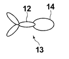
- FIG. 3A is a schematic diagram showing the antibody 12 and the fluorescent molecule 14 constituting the free molecule 13.
- FIG. 3B is a schematic diagram showing the antibody 12, the antigen 18, and the fluorescent molecule 14 constituting the binding molecule.
- the free molecules 13 and the binding molecules 15 move irregularly (Brownian motion) in the solution, and move and rotate in the solution. It is known that the Brownian motion of a molecule in a solution is affected by the absolute temperature, the volume of the molecule, the molecular weight (mass) of the molecule, the viscosity of the solvent, and the like.
- the binding molecule 15 has a volume larger than that of the free molecule 13 by the amount of the antigen 18, and does not easily perform Brownian motion in the solution.
- a method for detecting the binding molecule 15 from a change in Brownian motion by utilizing the ease of Brownian motion of the free molecule 13 and the binding molecule 15 in a solution is known. Since motion is used, detection sensitivity is limited.
- the biomolecule detection apparatus periodically aligns the binding molecules 15 in the solution using a laser, and detects only the signals that match the alignment period, thereby detecting the binding molecules 15. The contribution of the fluorescence generated from is calculated.
- the free molecules 13 and the binding molecules 15 in the solution When the free molecules 13 and the binding molecules 15 in the solution are irradiated with laser, the free molecules 13 and the binding molecules 15 in the solution receive an external force.
- the external force received by the binding molecule 15 by the laser is Fb
- the external force received by the free molecule 13 is Ff
- the free molecule 13 and the binding molecule 15 have different volumes and molecular weights depending on the presence or absence of the antigen 18, and therefore when the laser is irradiated.
- the magnitudes of the external forces received by Fb are different from each other and Fb> Ff.
- the free molecules 13 and the binding molecules 15 are different in the ease of Brownian motion of these molecules in the solution due to differences in volume or molecular weight. Since the free molecules 13 are smaller in volume and molecular weight than the binding molecules 15, they are more likely to perform Brownian motion. If the force required to orient the binding molecule 15 is Bb, and the force necessary to orient the free molecule 13 is Bf, then Bb> Bf. If Fb> Bb, the binding molecules 15 are oriented, and if Ff ⁇ Bf, the free molecules 13 are not oriented.
- the biomolecule detection apparatus calculates the contribution of fluorescence generated from the binding molecule 15 by periodically aligning only the binding molecule 15 and detecting only the signal that matches the alignment period. I do.
- the factors such as the absolute temperature of the solution, the volume of the molecule, the molecular weight, the viscosity of the solvent, and the laser intensity are determined so that Fb> Bb and Ff ⁇ Bf.
- the biomolecule detection apparatus mainly uses the absolute solution.
- the biomolecule detection apparatus has a function of adjusting the temperature of the solution and a function of adjusting the intensity of the laser.
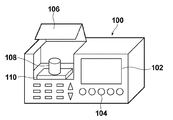
- FIG. 4A is an external perspective view of the biomolecule detection apparatus 100.
- a display unit 102 On the side surface of the biomolecule detection apparatus 100, there are a display unit 102, a user input unit 104, and an opening / closing unit 106.
- the display unit 102 displays measurement results and the like.
- the user input unit 104 is a part where the user sets a mode and inputs sample information.
- the opening / closing unit 106 is configured to be able to open and close the upper lid. The upper lid is opened when the specimen is set, and the upper lid is closed during measurement. With this configuration, external light is prevented from affecting the measurement.
- FIG. 4B is an external perspective view of the biomolecule detection apparatus 100 when the opening / closing part 106 is opened.
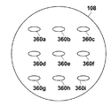
- the opening / closing part 106 When the opening / closing part 106 is opened, there are a reagent cup 108 and a holding table 110 inside.
- the reagent cup 108 is held on the holding table 110 and is detachable from the holding table 110.
- the reagent cup 108 is a cylindrical container for storing a solution.
- the user dispenses the sample into the reagent cup 108 and closes the upper lid to perform measurement.
- the biomolecule detection apparatus 100 has a reagent tank and a dispensing unit. When measurement is started, the dispensing unit sucks up the reagent from the reagent tank and dispenses it into the reagent cup 108.
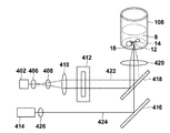
- FIG. 5 is a functional block diagram for explaining the main configuration of the biomolecule detection apparatus 100.
- the biomolecule detection apparatus 100 includes a display unit 102, a user input unit 104, a reagent cup 108, a reagent tank 112, a dispensing unit 114, an orientation control light source unit 116, an excitation light source unit 118, an AOD (Acousto Optical Defector) 120, an FG. (Function Generator) 122, light receiving unit 124, amplification unit 126, lock-in amplifier 127, A / D conversion unit 128, sampling clock generation unit 130, CPU 132, and dichroic mirror 138.
- a display unit 102 includes a display unit 102, a user input unit 104, a reagent cup 108, a reagent tank 112, a dispensing unit 114, an orientation control light source unit 116, an excitation light source unit 118, an AOD (Acousto Optical Defector) 120, an FG
- the reagent cup 108 is a container for reacting a reagent stored in the reagent tank 112 with a sample collected from a patient or the like.
- the reagent cup 108 is detachable from the biomolecule detection apparatus 100.
- the volume of the reagent cup 108 is about 120 ⁇ L, for example.
- the reagent tank 112 is a tank that stores a plurality of types of reagents.
- the free molecules 13 are stored as reagents in the reagent tank 112.
- the dispensing unit 114 is configured by a detachable pipette or a suction device. In accordance with an instruction from the CPU 132, the dispensing unit 114 sucks up the reagent used for measurement from the reagent tank 112 with a pipette and dispenses it into the reagent cup 108.
- the alignment control light source 116 irradiates the alignment control light 117 toward the AOD 120 and applies an external force to the binding molecules existing in the solution in the reagent cup 108 to align the binding molecules. That is, in this specification, the orientation control light source unit 116 corresponds to the orientation control means in the present invention.
- the orientation control light 117 for example, a laser having a wavelength of 980 nm and an output of 700 mW is used.
- the orientation control light 117 is a laser having a wavelength that the fluorescent molecules 14 do not absorb, and has an intensity that does not affect the dye of the fluorescent molecules 14 such as breakage.
- the orientation control light 117 has a width that illuminates the entire solution of the reagent cup 108.
- the excitation light source unit 118 excites the fluorescent molecules 14 by irradiating the reagent cup 108 with the excitation light 119 linearly polarized by the polarizer provided therein through the dichroic mirror 138.
- the excitation light for example, light having a wavelength of 532 nm and an output of 10 mW is used.
- the dichroic mirror 138 is a mirror that reflects light of a specific wavelength and transmits light of other wavelengths.
- the dichroic mirror 138 reflects the orientation control light 117 and transmits the excitation light 119.
- the AOD 120 switches the traveling direction of incident light by changing the internal refractive index based on the input voltage using the acousto-optic effect.
- the AOD 120 changes the internal refractive index based on a voltage input by a voltage signal output from an FG (Function Generator) 122 (hereinafter, an output signal to the AOD 120 is referred to as an alignment control signal), thereby controlling the alignment control light 117.
- an output signal to the AOD 120 is referred to as an alignment control signal
- Switch the direction of travel In other words, the traveling direction of the alignment control light 117 is determined by the alignment control signal generated by the FG 122.
- the AOD 120 alternates the direction in which the orientation control light 117 travels in the direction in which the reagent cup 108 is irradiated (indicated by an arrow 134 in the figure) and in the direction in which the dichroic mirror 138 is irradiated (indicated by an arrow 136 in the figure). Switch.
- the FG 122 is a device that can generate voltage signals having various frequencies and waveforms, and outputs a voltage signal to the AOD 120, the lock-in amplifier 127, and the sampling clock generator 130 in response to a command output from the CPU 132. .
- the CPU 132 controls the timing at which the AOD 120 switches the traveling direction of the orientation control light 117 by designating the orientation control signal output to the FG 122.
- the light receiving unit 124 is configured by a filter, a photodiode, or the like.
- the light receiving unit 124 is provided below the reagent cup 108, receives fluorescence 123 generated from the fluorescent molecules 14 in the reagent cup 108 at the lower part of the reagent cup 108, and receives the received light signal as an analog electrical signal (analog fluorescence data). ) And output to the amplifying unit 126.
- the amplifying unit 126 amplifies the analog fluorescence data output from the light receiving unit 124 and outputs the amplified data to the lock-in amplifier 127.
- the lock-in amplifier 127 converts the analog fluorescence data to a direct current.
- the lock-in amplifier 127 receives a square wave as a reference signal from the FG 122.
- the lock-in amplifier 127 detects a frequency component equal to the frequency of the reference signal from the analog fluorescence data output from the amplification unit 126.
- the lock-in amplifier 127 converts only a frequency component equal to the frequency of the reference signal into a DC signal by synchronous detection, and passes only the DC signal through a low-pass filter provided therein.
- the lock-in amplifier 127 outputs a DC signal to the A / D conversion unit 128.
- the lock-in amplifier 127 corresponds to the synchronous component extraction means in the present invention.
- the sampling clock generation unit 130 outputs to the A / D conversion unit 128 a sampling clock that specifies the timing at which the A / D conversion unit 128 samples the analog fluorescence data based on the voltage signal output from the FG 122.
- the A / D converter 128 samples the analog fluorescence data output from the lock-in amplifier 127 based on the sampling clock output from the sampling clock generator 130, and converts the sampled analog fluorescence data into digital data. To the CPU 132.
- the CPU 132 calculates the digital data output from the A / D conversion unit 128 and outputs the result to the display unit 102. Further, the CPU 132 receives an input from the user input unit 104 and issues an instruction command for operations of the orientation control light source unit 116, the excitation light source unit 118, the dispensing unit 114, and the FG 122. Specifically, the CPU 132 issues an ON / OFF command to the orientation control light source unit 116 and the excitation light source unit 118, and instructs the dispensing unit 114 to specify a reagent to be used and a dispensing operation. A start command is issued, and an instruction command and an output command for the waveform of the voltage signal to be output are issued to the FG 122.
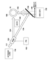
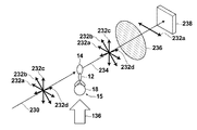
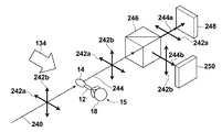
- FIG. 6 is a schematic view of the inside of the biomolecule detection apparatus 100 as viewed from the upper surface side in order to explain switching of the irradiation direction of the laser irradiated from the light source unit 116 for orientation control.
- the alignment control light 117 irradiated from the alignment control light source unit 116 is irradiated to the reagent cup 108 through the AOD 120.
- the orientation control light 117 has a width that illuminates the entire solution of the reagent cup 108.
- the AOD 120 alternately switches the irradiation direction of the alignment control light 117 irradiated from the alignment control light source unit 116 in two directions. Specifically, the AOD 120 advances the orientation control light 117 in the direction of the arrow 134 when a 5V orientation control signal is output from the FG 122, and when the FG 122 outputs a 0V orientation control signal. Then, the orientation control light 117 is advanced in the direction of the arrow 136.
- the orientation control light 117 traveling in the direction of the arrow 134 is incident on the side surface of the reagent cup 108 as it is.
- the orientation control light 117 traveling in the direction of the arrow 136 is reflected by the dichroic mirror 138, travels in a direction perpendicular to the direction of the arrow 134, and enters the side surface of the reagent cup 108. If the reagent cup 108 viewed from the top is compared to a clock face, the orientation control light 117 traveling in the direction of the arrow 134 enters from the 9 o'clock position, proceeds in the 3 o'clock direction, and proceeds in the direction of the arrow 136.
- the alignment control light 117 enters from the 6 o'clock position and travels in the 12 o'clock direction. That is, the direction in which the orientation control light 117 traveling in the direction of the arrow 134 enters the reagent cup 108 and the direction in which the orientation control light 117 advanced in the direction of the arrow 136 enters the reagent cup 108 are orthogonal to each other.
- the dichroic mirror 138 reflects only light having the wavelength used for the orientation control light 117 and transmits light having other wavelengths. Excitation light 119 emitted from the excitation light source unit 118 passes through the dichroic mirror 138, travels in the same direction as the orientation control light 117 reflected by the dichroic mirror 138, and enters the side surface of the reagent cup 108.
- the biomolecule detection apparatus 100 controls the AOD 120 by inputting an orientation control signal from the FG 122, whereby the directions in which the orientation control light 117 enters the reagent cup 108 are different from each other by 90 degrees. It can be switched alternately in one direction.
- the biomolecule detection apparatus 100 is configured so that the orientation control light 117 traveling in directions other than the directions indicated by the arrows 134 and 136 is not irradiated to the reagent cup 108. ing.
- the orientation control light 117 is incident on the side surface of the cylindrical reagent cup 108 when traveling in either direction of the arrows 134 and 136. Since the reagent cup 108 is a cylinder, even if the traveling direction of the orientation control light 117 is switched, the shape of the side surface of the reagent cup 108 on which the orientation control light 117 is incident is the same.
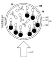
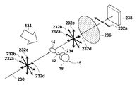
- FIG. 7A is a schematic diagram showing one irradiation direction of the orientation control light 117 and the orientation direction of the binding molecule
- FIG. 7B shows the other irradiation direction of the orientation control light 117 and the orientation direction of the binding molecule.
- FIG. 7A and 7B are views of the reagent cup 108 as viewed from above.
- the “orientation direction” with respect to free molecules and binding molecules means the direction in which antibodies and fluorescent molecules are arranged in a state where the switching of the orientation is completed.
- the binding molecules 15 in the reagent cup 108 irradiated with the orientation control light 117 are subjected to an external force by the orientation control light 117 and are oriented in a specific direction.
- the external force due to the alignment control light 117 is generated as a reaction in which the alignment control light 117 strikes the binding molecule 15 and scatters.
- the direction in which the force is applied is determined by the relationship with the direction (the direction in which the fluorescent molecule 14, the antibody 12, and the antigen 18 are arranged).
- the binding molecules 15 irradiated with the alignment control light 117 traveling from the left to the right of the paper surface receive a force in a direction (rotation direction) rotated by the alignment control light 117, and the alignment control light 117.
- the external force of the orientation control light 117 is stabilized in the direction in which the rotational force in various directions exerted on the binding molecule 15 is balanced.
- the binding molecule 15 receives an external force of clockwise rotation or counterclockwise rotation when the traveling direction of the alignment control light 117 and the longitudinal direction of the binding molecule 15 do not face the same direction.
- the binding molecules 15 in the reagent cup 108 are all oriented in the same direction (a direction in which the traveling direction of the orientation control light 117 and the longitudinal direction of the binding molecule 15 are parallel) when irradiated with the orientation control light 117. That is, the transition moments of the fluorescent molecules 14 associated with all the binding molecules 15 are aligned in the same direction.
- the free molecules 13 in the reagent cup 108 are not oriented because the force for performing the Brownian motion is stronger than the external force received by the orientation control light 117, and the Brownian motion is performed in the solution.
- the binding molecules 15 that are oriented toward the right side of the paper receive a force in the direction of rotating counterclockwise.
- the binding molecule 15 that has received the orientation control light 117 traveling from the bottom to the top of the paper is stabilized in a direction perpendicular to the direction oriented by the orientation control light 117 traveling from the left to the right of the paper.
- the transition moments of the fluorescent molecules 14 attached to all the binding molecules 15 are aligned so as to be directed in the same direction.
- the free molecules 13 in the reagent cup 108 are not oriented because the force for performing the Brownian motion is stronger than the external force received by the orientation control light 117, and the Brownian motion is performed in the solution.
- the orientation direction of the binding molecules 15 in the solution can be switched by changing the irradiation direction of the orientation control light 117.
- the direction of the transition moment of the fluorescent molecule 14 accompanying the binding molecule 15 oriented by the orientation control light 117 proceeding in the direction of the arrow 134 is parallel to the direction in which the linearly polarized excitation light 119 vibrates. And the excitation efficiency of the fluorescent molecules 14 is maximized.
- the direction of the transition moment of the fluorescent molecule 14 associated with the binding molecule oriented by the orientation control light 117 proceeding in the direction of the arrow 136 is perpendicular to the direction in which the linearly polarized excitation light 119 vibrates. The excitation efficiency of becomes zero.
- switching of the irradiation direction of the orientation control light 117 by the AOD 120 switches the excitation efficiency of the fluorescent molecule 14 accompanying the binding molecule 15 with respect to the linearly polarized excitation light 119 between maximum and minimum (when excitation is not possible). It will be.
- the orientation control signal input to the AOD 120 is 5V
- the excitation efficiency of the fluorescent molecule 14 associated with the binding molecule 15 is maximized
- the orientation control signal input to the AOD 120 is 0V
- the excitation efficiency is associated with the binding molecule 15.
- the excitation efficiency of the fluorescent molecule 14 is minimized.
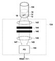
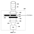
- FIG. 8 is a schematic diagram illustrating a detailed configuration of the light receiving unit 124.
- the light receiving unit 124 includes a lens 142, a filter 144, a polarizer 146, a lens 148, and a PD (photodiode) 150.
- the light receiving unit 124 receives fluorescence from the bottom side of the reagent cup 108.
- Fluorescence 147 generated from the fluorescent molecules 14 in the reagent cup 108 and incident on the left side portion of the light receiving unit 124 and the right side portion of the light receiving unit 124 is condensed and collimated by the lens 142.
- the light enters the PD 150 through the filter 144, the polarizer 146, and the lens 148.
- fluorescence also exists between the fluorescence 147 and the fluorescence 149, and the behavior thereof can be predicted by those skilled in the art, and thus the description thereof is omitted.
- the filter 144 is a band-pass filter that cuts light other than fluorescence generated from the fluorescent molecules 14 and prevents light other than fluorescence, such as excitation light, from entering the PD 150.
- the polarizer 146 transmits only the light polarized in the same direction as the vibration direction of the linearly polarized excitation light 119.
- the excitation light scattered in the reagent cup 108 and the fluorescence emitted from the fluorescent molecules 14 while switching the orientation directions of the free molecules and the binding molecules are different in vibration direction from the original excitation light. Therefore, the light cannot pass through the polarizer 146.
- the PD 150 is configured by an APD (Avalanche Photodiode), receives the fluorescence condensed by the lens 148, generates a charge corresponding to the intensity of the fluorescence, and outputs it to the amplification unit 126.
- APD Anagonal Photodiode
- the light receiving unit 124 converts the fluorescence generated from the fluorescent molecules 14 whose orientation has been switched into charges.
- the light receiving unit 124 since the light receiving unit 124 receives fluorescence on the bottom surface side of the reagent cup 108, the light receiving unit 124 is not easily affected by the orientation control light 117 and the excitation light 119.
- “the switching of the orientation has been completed” means that the molecule has become stable with respect to the external force due to the orientation control light after switching the irradiation direction of the orientation control light.
- FIG. 9 is a diagram schematically showing the flow from sample preparation to disposal.
- whole blood 156 collected from a patient is centrifuged at 50 ⁇ L to separate plasma 16.
- the separated plasma 16 is set in the specimen setting unit 152 of the biomolecule detection apparatus 100. The work so far is done by the user.
- the biomolecule detection apparatus 100 dispenses the plasma set in the sample setting unit 152 into an unused reagent cup 108 stocked in the reagent cup stock unit 160. Subsequently, the biomolecule detection apparatus 100 sucks up the anti-PSA antibody in the reagent tank 112 with the pipette 158 and dispenses it into the reagent cup 108.
- the biomolecule detection apparatus 100 in which the plasma and the anti-PSA antibody are placed in the reagent cup 108 causes the antigen-antibody reaction by vibrating the reagent cup 108 with a built-in vortex mixer while controlling the temperature at 37 ° C. Thereafter, the biomolecule detection apparatus 100 performs irradiation with excitation light and fluorescence detection, and discards the reagent cup 108 in the built-in trash box 154 after the fluorescence detection is completed.
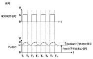
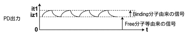
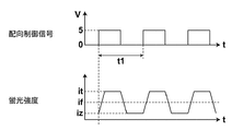
- FIG. 10B An example of an orientation control signal output by the FG 122 during measurement, an example of a PD output output by the PD 150 during measurement, and an example of a lock-in amplifier output output by the lock-in amplifier 127 during measurement are shown in FIG. 10B. Shown in Here, for ease of explanation, graphs are schematically shown for the PD output and the lock-in amplifier output.
- the orientation control signal output from the FG 122 is 0 V before measurement.
- the orientation control signal is a square wave having a period of 2T that outputs a signal of 5 V from 0 to T (seconds) and outputs a 0 V signal from T to 2 T (seconds).
- the orientation control signal is 0 V, the orientation control light 136 is irradiated to the reagent cup 108, and all the binding molecules are oriented in the same direction.
- the biomolecule detection apparatus 100 sets the orientation control signal to 5 V at time T1 and irradiates the reagent cup 108 with excitation light. Thereafter, when the orientation control signal becomes 5V, the AOD 120 switches the traveling direction of the orientation control light 117, and the traveling direction of the orientation control light 117 is switched from the direction of the arrow 136 to the direction of the arrow 134. As the direction of travel of the orientation control light 117 is switched, the irradiation direction of the orientation control light 117 on the reagent cup 108 is also switched by 90 degrees.
- the orientation direction of the binding molecule 15 is switched, and fluorescence 123 is generated when the vibration direction of the excitation light 119 and the direction of the transition moment of the fluorescent molecule 14 are not perpendicular to each other. . Most of the fluorescence generated from the fluorescent molecules 14 accompanying the binding molecules 15 in the course of switching the orientation is blocked by the polarizer 146 because it is not polarized.
- the direction of transition moment is parallel to the vibration direction of the excitation light 119, and the excitation efficiency is maximized. Since the fluorescence generated from the fluorescent molecules accompanying the binding molecules 15 whose orientation has been switched is polarized in the same direction as the excitation light, it reaches the PD 150 without being blocked by the polarizer 146.
- the PD output outputs the value iz.
- the PD output iz is a value including fluorescence generated from the fluorescent molecules 14 associated with some free molecules 13 in the solution and a noise component derived from the device or the like. Since the fluorescent molecules 14 associated with the binding molecules 15 are not excited when the orientation control signal is 0 V, they do not contribute to the PD output.
- the PD output When the orientation control signal changes from 0V to 5V and the fluorescence 123 generated by the fluorescent molecules 14 accompanying the binding molecules 15 whose orientation has been changed reaches the PD, the PD output also increases from iz. Most of the fluorescence 123 generated from the fluorescent molecules 14 accompanying the binding molecules 15 in the middle of switching the orientation is blocked by the polarizer 146 because it is not polarized.
- the PD output increases as the number of binding molecules 15 for which the switching of the orientation is completed increases, and when the switching of the orientations of all the binding molecules 15 is completed, the PD output is saturated at the value it.
- the orientation control signal becomes 0V after the output of 5V continues for T seconds.
- This T second takes a period longer than the switching of the orientation of all the binding molecules 15 is completed, that is, a period longer than the PD output is saturated at the value it.
- the orientation control signal changes from 5V to 0V.
- the orientation control signal changes from 5 V to 0 V, the direction of the transition moment of the fluorescent molecule 14 associated with the binding molecule 15 and the vibration direction of the excitation light 119 become perpendicular to each other, and the excitation efficiency of the fluorescent molecule 14 associated with the binding molecule 15 Becomes 0 and fluorescence 123 is not generated.
- the PD output gradually decreases to iz.
- the fluorescence 123 generated from the fluorescent molecules 14 accompanying the binding molecules 15 in the middle of switching the orientation is blocked by the polarizer 146 because most of the fluorescence 123 is not polarized.
- the PD output increases and becomes saturated at the value it.
- the period during which the orientation control signal was set to 0 V was set to the same T seconds as the period during which the orientation control signal was set to 5 V. This is because, under the condition that the output of the orientation control light 117 is constant, the time required to complete the switching of the orientation of the binding molecules 15 in the solution is the same as when the orientation control signal is changed from 0 V to 5 V. This is because it is almost the same as when V is changed from 5V to 0V.
- the lock-in amplifier 127 detects a component that repeatedly increases and decreases in synchronization with the reference signal from the input signal.
- the same signal as the orientation control signal is input to the lock-in amplifier 127 as a reference signal. That is, the lock-in amplifier 127 detects a component synchronized with the orientation control signal from the PD output.
- the PD output is a periodic signal having a period of 2T as in the case of the orientation control signal, but what contributes to the periodic component of the PD output is the fluorescence associated with the binding molecules 15 oriented by the orientation control signal. Fluorescence generated from the molecule 14.
- the lock-in amplifier output is initially an unstable output that repeatedly increases and decreases, but gradually converges to the value S.
- the value S is the PD output based on the total amount of fluorescence generated from the fluorescent molecule 14 associated with the binding molecule 15.
- the CPU 132 calculates the concentration C of the detection target substance from the lock-in amplifier output S. Specifically, it is obtained by the following equation (1).
- C f (S) (1)
- f (S) is a calibration curve function.
- the biomolecule detection apparatus 100 has a calibration curve function different for each measurement item in advance, and converts the measurement value S into a diagnostic value C.
- the CPU 132 outputs the obtained diagnostic value C to the display unit 102.
- the orientation direction of the binding molecule 15 in the solution can be switched by switching the irradiation direction of the orientation control light 117.
- the orientation direction of the binding molecule 15 by the orientation control light 117 is the direction in which the direction of the transition moment of the fluorescent molecule 14 accompanying the binding molecule 15 and the vibration direction of the linearly polarized excitation light are parallel to each other, or the binding molecule 15
- the biomolecule detection apparatus 100 it is possible to switch between the case where the fluorescent molecule 14 accompanying the binding molecule 15 is excited by the linearly polarized excitation light and the case where it is not excited by switching the irradiation direction of the orientation control light 117. It becomes.
- the lock-in amplifier 127 detects a component synchronized with the alignment control signal instructing switching of the irradiation direction of the alignment control light 117 from the received fluorescence data. 15 can be calculated, and the concentration of the detection target substance can be accurately measured with a simple configuration.
- the biomolecule detection apparatus 100 switches all the orientations of the binding molecules 15 in the same direction by an external force by the orientation control light 117, so that the measurement is performed using a random motion called Brownian motion. Therefore, highly sensitive measurement can be performed.
- Alexa Fluor 568 is used as the fluorescent molecule, but the fluorescent molecule is not limited to these.
- the fluorescent molecule may be anything as long as it has a transition moment, is excited by excitation light, and generates light detectable by PD.
- the case of using an antigen-antibody reaction has been described as an example.
- the combination of a detection target substance and a substance that specifically binds to the detection target substance is not limited to the case described here.
- detecting an antibody using an antigen detecting a nucleic acid that hybridizes with the nucleic acid using a specific nucleic acid, binding a nucleic acid-binding protein using a nucleic acid, a ligand is used. It can also be applied to the detection of receptors using, the detection of lectins using sugars, the use of protease detection, the use of higher order structural changes, and the like.
- the period during which the orientation control signal is 5 V or 0 V based on the molecular weight of the binding molecule, the volume, the viscosity of the solvent, the temperature of the solution, or the like.
- the time required from the time when the irradiation direction of the orientation control light 117 to the binding molecule starts to be switched to the completion of the orientation switching is determined by the molecular weight of the binding molecule, the volume, the viscosity of the solvent, or the temperature of the solution. It depends on the ease of rotation of the molecule. If the binding molecule is difficult to rotate in the solution, the time required for completing the switching of the orientation of the binding molecule becomes long.
- the period during which the orientation control signal is set to 5 V or 0 V is set to the extent that the switching of the orientation is completed. It is desirable to make it longer. Further, it is desirable to increase the period for setting the orientation control signal to 5 V or 0 V as the molecular weight of the binding molecule increases, and to shorten the period for setting the orientation control signal to 5 V or 0 V as the molecular weight of the binding molecule decreases.
- a laser having a wavelength of 980 nm and an output of 700 mW is used as the orientation control light 117, but the laser used as the orientation control light is not limited to this.
- the wavelength and output of the orientation control light 117 are determined based on the ease of rotation of the free molecule and the binding molecule in the solution due to the volume, molecular weight, solvent viscosity, absolute temperature, etc. of the free molecule and the binding molecule. It is desirable that only the output be oriented.
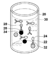
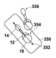
- Embodiment 2 are schematic diagrams showing an outline of an antigen-antibody reaction of the biomolecule detection apparatus according to Embodiment 2 of the present invention.
- Embodiment 2 two types of antibodies are used, and two types of antigens are detected in a uniform solution.
- the antibody 22 and the antibody 26 are placed in the reagent cup 20.
- the antibody 22 and the antibody 26 are labeled with a fluorescent molecule 24 and a fluorescent molecule 28, respectively.
- an antigen 32 that specifically binds to the antibody 22 is present in the specimen, an antigen-antibody reaction occurs between the antibody 22 and the antigen 32, and the antibody 22 And antigen 32 specifically binds.
- an antigen 34 that specifically binds to the antibody 26 is present in the sample, an antigen-antibody reaction occurs between the antibody 26 and the antigen 34, and the antibody 26 and the antigen 34 bind specifically.
- the antibody 22, antigen 32 and fluorescent molecule 24 that have undergone antigen-antibody reaction are referred to as binding molecule 1
- antibody 22 and fluorescent molecule 24 that have not undergone antigen-antibody reaction are referred to as free molecule 1.
- the antibody 26, antigen 34 and fluorescent molecule 28 that have undergone antigen-antibody reaction are referred to as binding molecule 2
- antibody 26 and fluorescent molecule 28 that have not undergone antigen-antibody reaction are referred to as free molecule 2.
- the antigen 32 as the detection target substance is PSA and the antigen 34 is an SCC (Squamous Cell Carcinoma) antigen.
- an anti-PSA antibody that specifically binds to PSA is used as the antibody 22
- an SCC antibody that specifically binds to the SCC antigen is used as the antibody 26.
- Alexa Fluor 568 (trade name of Molecular Probes) was used as the fluorescent molecule 24
- Alexa Fluor 555 (trade name of Molecular Probes) was used as the fluorescent molecule 28.
- Alexa Fluor 555 emits fluorescence having a wavelength of about 540-700 nm, and emits fluorescence having a wavelength of about 570 nm most strongly.
- the biomolecule detection apparatus irradiates a solution containing two types of free molecules and two types of binding molecules with excitation light to detect or quantify the target binding molecules.
- FIG. 12 is a block diagram showing the main configuration of the biomolecule detection apparatus 200 according to Embodiment 2 of the present invention.
- symbol is attached
- the biomolecule detection apparatus 200 is mainly different from the configuration of the biomolecule detection apparatus 100 shown in Embodiment 1 in a light receiving unit 202, a dispensing unit 204, a reagent tank 206, and a CPU 208.
- the dispensing unit 204 sucks up two types of antibodies from the reagent tank 206 in which a plurality of antibodies are contained in separate containers, and dispenses them into the reagent cup 108.
- the light receiving unit 202 detects the fluorescence generated from the fluorescent molecules in the reagent cup 108, and receives the command (S1) from the CPU 208 and the fluorescence generated from the fluorescent molecules 24 and the fluorescence generated from the fluorescent molecules 28. And can receive light separately.
- the CPU 208 calculates the digital data output from the A / D conversion unit 128 and outputs the result to the display unit 102. Further, the CPU 208 receives an input from the user input unit 104 and issues an instruction command for the operations of the orientation control light source unit 116, the excitation light source unit 118, the dispensing unit 204, the FG 122, and the light receiving unit 202. Specifically, the CPU 208 issues ON / OFF commands to the orientation control light source unit 116 and the excitation light source unit 118, and instructs the dispensing unit 204 to specify a reagent to be used and a dispensing operation. A start command is issued, an instruction command and an output command for a waveform of a voltage signal to be output are given to the FG 122, and a filter switching command is given to the light receiving unit 202.
- FIG. 13 is a schematic diagram illustrating a detailed configuration of the light receiving unit 202 in the biomolecule detection apparatus 200 according to the second embodiment.
- the filter switching unit 210 in the light receiving unit 202 includes two types of filters, a filter 212 and a filter 214.
- the two types of filters are movable, and the filters through which the light condensed and collimated by the lens 142 pass can be switched.
- the fluorescence 216 generated from the fluorescent molecules 14 in the reagent cup 108 and incident on the left side portion of the light receiving unit 202 on the paper surface and the fluorescent light 218 incident on the right side portion of the light receiving unit 202 on the paper surface are collected by the lens 142 and are filtered by the filter 212 or The light enters the polarizer 146 through the filter 214 and enters the PD 150 through the lens 148.
- fluorescence also exists between the fluorescence 216 and the fluorescence 218, and the behavior thereof can be predicted by those skilled in the art, and thus the description thereof is omitted.
- the filter switching unit 210 receives a command from the CPU 208 and switches a filter to be used.
- a light receiving side filter of a SpRed-A filter (trade name of Semirock) set is used as the filter 212.
- the light receiving side filter of the SpRed-A filter set is a bandpass filter that transmits light having a wavelength of about 605 nm to 650 nm.
- a light receiving side filter of a SpOr-A filter (trade name of Semirock) is used as the filter 214.
- the light receiving side filter of the SpOr-A filter set is a bandpass filter that transmits light having a wavelength of about 575 to 600 nm.
- the measurement operation of the biomolecule detection apparatus 200 is basically the same as the measurement operation of the biomolecule detection apparatus 100 described in the first embodiment, but differs in small points. Since the reason why the free molecule and the binding molecule can be detected separately has been described in the first embodiment, here, a method for separating and detecting two types of binding molecules will be described.
- the biomolecule detection apparatus 200 first determines which of the two types of binding molecules is detected first. This can be arbitrarily determined by the user through the user input unit 104 or the like. Here, the binding molecule 1 having Alexa Fluor 568 as a fluorescent molecule is detected first.
- the CPU 208 issues a command to instruct the filter switching unit 210 in the light receiving unit 202 to use the filter 212.
- the filter switching unit 210 receives a command from the CPU 208 and moves the filter 212 to a position where light condensed and collimated by the lens 142 passes.
- the orientation control signal changes to 5 V and excitation light is irradiated toward the reagent cup 108, the fluorescent molecules 24 and the fluorescent molecules 28 in the solution generate fluorescence.
- the fluorescence generated from the fluorescent molecules 24 and 28 is condensed and collimated by the lens 142 and enters the filter 212. Since the filter 212 passes only light having a wavelength of about 605 nm to 650 nm, the fluorescence generated from the fluorescent molecule 24 passes through the filter, and the fluorescence generated from the fluorescent molecule 28 is almost completely blocked by the filter. In this way, the light receiving unit 202 can detect only the fluorescence generated from the fluorescent molecules 24.
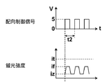
- FIG. 14A shows a PD output as a result of measuring the number of cycles of the orientation control signal by the biomolecule detection apparatus 200 and detecting the fluorescence generated from the fluorescent molecules 24.
- a graph is schematically shown for easy calculation.
- the PD output outputs a signal having the same cycle as that of the orientation control signal.
- the lock-in amplifier detects a component synchronized with the period of the orientation control signal from the PD output, and outputs a value S1.
- the CPU 208 calculates the concentration of the binding molecule 1 from the obtained value S1. Specifically, the measured value S1 is converted to the concentration C1 using the calibration curve function f1 (S) as in the first embodiment. The CPU 208 outputs the obtained density C1 to the display unit 102.
- the biomolecule detection apparatus 200 measures the binding molecule 2.
- the CPU 208 issues a command to instruct the filter switching unit 210 in the light receiving unit 202 to use the filter 214.
- the filter switching unit 210 receives a command from the CPU 208 and moves the filter 214 to a position where light condensed and collimated by the lens 142 passes. Since the filter 214 passes only light having a wavelength of about 575 nm to 600 nm, the fluorescence generated from the fluorescent molecule 24 is blocked by the filter, and the fluorescence generated from the fluorescent molecule 28 passes through the filter. In this way, the light receiving unit 202 can detect only the fluorescence generated from the fluorescent molecules 28.
- FIG. 14B shows a PD output as a result of measuring the number of cycles of the orientation control signal by the biomolecule detection apparatus 200 and detecting the fluorescence generated from the fluorescent molecules 28.
- a graph is schematically shown for easy calculation.
- the PD output outputs a signal having the same cycle as that of the orientation control signal.
- the switching timing of the orientation control signal when measuring the binding molecule 2 is different from that when measuring the binding molecule 1. This is because the binding molecule 1, the free molecule 1, the binding molecule 2 and the free molecule 2 have different volumes and molecular weights, so that the time required for each molecule to complete the switching of the orientation is different.
- the timing at which the increase and decrease of the PD output are switched is the same, but the maximum value and the minimum value of the PD output are changed. Are different from each other. This is caused by the difference in concentration between the binding molecule 1 and the binding molecule 2 in the solution and the difference in concentration between the free molecule 1 and the free molecule 2 in the solution.
- the CPU 208 obtains the concentration of the binding molecule 2 from the obtained value S2. Specifically, the measured value S2 is converted into the concentration C2 using the calibration curve function f2 (S). The CPU 208 outputs the obtained density C2 to the display unit 102.
- the biomolecule detection apparatus 200 in addition to the configuration of the biomolecule detection apparatus 100 described in Embodiment 1, it specifically binds to the detection target substance.
- Two types of antibodies and fluorescent molecules were used as substances, and the filter switching unit 210 was configured to be able to switch between two types of filters. Therefore, by using a filter corresponding to the fluorescent molecule associated with the binding molecule containing the detection target substance, only the fluorescence generated from the fluorescent molecule accompanying the binding molecule containing the detection target substance can be detected. The concentrations of the two types of detection target substances contained in the specimen can be accurately measured.
- Alexa Fluor 568 and Alexa Fluor 555 are used as fluorescent molecules, but the fluorescent molecules are not limited to these.
- a plurality of substances that specifically bind to each of the plurality of detection target substances may be labeled with a plurality of fluorescent molecules that have different fluorescence wavelengths, excitation wavelengths, or fluorescence lifetimes to such an extent that they can be separated by a filter.
- the detection target substance and the substance that specifically binds to the detection target substance is not limited thereto.
- the present invention can be applied to the detection of an antibody using an antigen, a nucleic acid that hybridizes with a specific nucleic acid and the nucleic acid, a nucleic acid and a nucleic acid-binding protein, a ligand and a receptor, a sugar and a lectin, a protease detection, a higher-order structure It can also be applied to changes and the like.
- the case where there are two types of detection target substances has been described.
- the number of detection target substances may be larger.
- a plurality of substances that specifically bind to each of the plurality of detection target substances are used, the plurality of substances are labeled with a plurality of different fluorescent molecules, and fluorescence generated from each fluorescent molecule is emitted.
- the respective detection target substances can be separated from each other and detected.
- the types of detection target substances increase, the types of fluorescent molecules also increase, and a plurality of fluorescences generated from a plurality of fluorescent molecules will be mixed, so it may be difficult to separate the fluorescence only with a filter. .
- separation of fluorescence can be facilitated by increasing the types of excitation light.
- the absorbance of the fluorescent molecule depends on the wavelength of the excitation light, and there is a wavelength band that is easily absorbed for each type of fluorescent molecule. Therefore, by changing the wavelength of the excitation light, only some of the fluorescent molecules generate fluorescence, and the separation of the fluorescence with the filter becomes easy. Further, by using a bandpass filter having a narrower pass band, it is possible to easily detect fluorescence generated from the target fluorescent molecule.
- a filter is used as a spectroscopic means for dispersing light in the light receiving unit, but it is not always necessary to use a filter.
- light may be dispersed using a diffraction grating or a prism, and only light having a specific wavelength may be received by a photodiode.
- the switching of the orientation of the binding molecules in the solution is not limited to using a laser, and a magnetic method or an electrical method may be used as long as only the binding molecules can be oriented.
- the irradiation direction of the orientation control light does not necessarily have to be switched by AOD.
- the orientation control light irradiation direction may be switched by providing a plurality of alignment control light source units and switching the light source itself, or the orientation control light irradiation direction may be switched using a drive mirror or the like.
- the alignment molecules are aligned using a linearly polarized laser as the alignment control light, and the liquid crystal phase modulation device that can be controlled by a ⁇ / 2 wavelength plate or an electric signal is used to switch the direction in which the laser is linearly polarized.
- the orientation direction of molecules may be switched.
- the traveling direction of the orientation control light 117 is a direction in which the direction of the transition moment of the fluorescent molecule associated with the binding molecule and the vibration direction of the linearly polarized excitation light are parallel to each other
- the irradiation direction of the orientation control light is alternately switched in two directions orthogonal to each other, in which the direction of the transition moment of the fluorescent molecule associated with the binding molecule and the vibration direction of the linearly polarized excitation light are perpendicular to each other. It is not always necessary to switch between the two directions orthogonal to each other.
- one of the two irradiation directions of the orientation control light to be set is the direction of the transition moment of the fluorescent molecule associated with the binding molecule and the vibration direction of the excitation light linearly polarized And the direction in which the excitation light that is linearly polarized cannot excite the fluorescent molecule is sufficient.
- the fluorescent molecules are oriented in a direction in which the excitation light cannot excite the fluorescent molecules, no fluorescence is generated, so that the PD output is only the output due to some free molecules and noise caused by the device.
- the time required to complete the switching of the orientation of the binding molecule is maximized, and the S / N is the best.
- the angle formed by the two directions in which the orientation control light 117 travels is 60 degrees
- the switching of the orientation of the binding molecule is completed as compared with the case where the two travel directions of the orientation control light 117 are orthogonal to each other.
- the time required until the time is shortened, and the time required for the measurement is also shortened.
- the angle formed by the two directions in which the orientation control light 117 travels is smaller than 90 degrees, the time required to complete the switching of the orientation of the binding molecule is shortened, and the measurement time is also shortened.
- orientation direction of the orientation control light 117 may be switched alternately, and the direction of the transition moment of the fluorescent molecule associated with the binding molecule and the vibration direction of the linearly polarized excitation light are not necessarily included. Also good. If there is a time difference in switching the orientation of the binding molecule, the difference appears in the fluorescence data, so the presence of the binding molecule can be confirmed.
- the number of reagent cups is not necessarily one, and a plurality of reagent cups are provided in the apparatus. It is good also as a structure which can provide and can set a some sample. In that case, if the apparatus is configured to perform the measurement by sequentially moving the reagent cups to the measurement position, a plurality of specimens can be automatically measured.
- an example using an antibody labeled with a fluorescent molecule has been described.
- the antibody and antigen binding and the antibody and fluorescent molecule binding may be performed simultaneously in the reagent cup.
- the user prepares the antibody and the fluorescent molecule in separate reagent tanks, and at the time of measurement, the biomolecule detection device dispenses the antibody, the fluorescent molecule, and the specimen into the respective reagent cups and causes them to react.
- orientation control light source unit 116 and the excitation light source unit 118 may be detachable and may be replaced with appropriate ones according to the detection target substance, fluorescent molecules, and the like.
- the predetermined time interval for switching the direction of orientation control is based on the molecular weight or volume of each of the detection target substance, the substance that specifically binds to the detection target substance and the fluorescent molecule, and the strength of the external force of the orientation control means. It is desirable to obtain the time required to complete the switching of the orientation of the binding molecule and set that time as a predetermined time interval. In such a case, even after the switching of the orientation of all the binding molecules is completed, the orientation control light is not irradiated in the same direction, and the power consumption can be reduced. Further, the measurement is not continued until unnecessary, and the measurement time can be shortened.
- the time required to complete the switching of the orientation of all binding molecules may be obtained based on the PD output or the A / D converter output. For example, if you repeat the measurement for several cycles, you can roughly know how long it will take for each output to saturate. The time interval may be determined.
- each molecule When controlling the orientation of molecules by orientation control light, a complicated mechanism is not required compared to controlling the orientation of molecules by magnetic force or the like. For example, in order to control the orientation of molecules using magnetic force, each molecule must have magnetism or it is necessary to prepare a molecule with magnetism and bind it to the molecule whose orientation is to be controlled. Preparation for measurement is complicated.
- the sample is not limited to plasma separated from whole blood, and the detection target substance is dispersed in the solution. If so, body fluids such as urine and sputum can be used as the specimen.
- the binding molecules are oriented and the free molecules are not oriented has been described as an example.
- the free molecules are not necessarily oriented. Even when free molecules are oriented by the orientation control light, the free molecules and the binding molecules have different volumes and molecular weights, and the orientation speeds are different. For this reason, even when the irradiation direction of the orientation control light is switched, the time required for completing the switching of the orientation of these molecules is different from each other, and therefore the periods in which fluorescence is generated are also different. Therefore, if a reference signal is input to the lock-in amplifier that takes twice the time required for switching the orientation of the binding molecule after the orientation control signal is switched, it will be generated from the fluorescent molecule associated with the binding molecule.
- the fluorescent component to be detected can be detected.
- measurement can be performed in a liquid phase in which an antigen, an antibody, and a fluorescent molecule are dispersed in a liquid.
- pretreatment is simple.
- the antigen and free molecules are not fixed to the solid phase, the antigen and free molecules can freely move around in the solution, and there is an advantage that the reaction is faster than the measurement in the solid phase.
- each embodiment according to the present invention does not examine changes in the degree of polarization of fluorescence due to changes in Brownian motion as in the conventional fluorescence polarization method, so that the components of the specimen affect the fluorescence lifetime of the fluorescent molecule. Even if given, it has little effect on the measurement.
- the case where the solution is irradiated with the excitation light 119 linearly polarized in one direction that is, the case where the solution is irradiated with the excitation light 119 having a single polarization plane is described.
- the excitation light 119 does not necessarily need to be linearly polarized light having a single polarization plane.
- the excitation light 119 only needs to have at least one linearly polarized light component in a specific direction.
- the light having a linearly polarized light component in a specific direction means that the relationship between the direction of the transition moment of the fluorescent molecule and the vibration direction of the linearly polarized light component of the excitation light changes due to the change in the orientation direction of the fluorescent molecule,
- it may be configured to irradiate randomly polarized excitation light and provide an analyzer in front of the light receiving unit so as to receive only linearly polarized light components in a specific direction from the fluorescence generated from the fluorescent molecules.
- the random polarization means that the vibration direction of light is random, and linearly polarized light components that vibrate in various directions exist.
- 15A and 15B are conceptual diagrams showing the orientation direction of the fluorescent molecules 14 and the vibration direction of the randomly polarized excitation light 230 when irradiated with the orientation control lights 136 and 134, respectively.
- the vibration directions 232a to 232d of the excitation light 230 represent the vibration directions of light in a plane perpendicular to the traveling direction of the excitation light 230.
- 15A and 15B show that the vibration directions of the excitation light 230 are various directions depending on the vibration directions 232a to 232d.
- the illustrated components but also more components in all angular directions are present. include.
- the fluorescent molecule when a fluorescent molecule stationary in a solution is excited with linearly polarized excitation light, the fluorescent molecule generates fluorescence polarized in the same direction as the polarization direction of the excitation light.
- the randomly polarized fluorescence 234 is also generated from the fluorescent molecules 14 associated with the binding molecules.
- the analyzer 236 transmits a component that vibrates in a specific direction among the randomly polarized fluorescence 234 generated from the fluorescent molecules 14 and blocks a component that vibrates in the other direction.
- the light transmitted through the analyzer 236 becomes light that vibrates only in a specific direction.
- the component of the fluorescence 234 that vibrates in a specific direction that can pass through the analyzer 236 is a component that vibrates in the vibration direction 232a. Therefore, the vibration direction of the fluorescence 234 that has passed through the analyzer 236 is only the vibration direction 232a in FIGS. 15A and 15B.
- the component that vibrates in the vibration direction 232 a included in the fluorescence 234 is generated by being excited by the excitation light component linearly polarized in the vibration direction 232 a of the excitation light 230. That is, only the fluorescent component generated by being excited by the excitation light component linearly polarized in the vibration direction 232 a included in the excitation light 230 can reach the photodiode 238. Therefore, with such a configuration, even when randomly polarized light is used as the excitation light 230, the same measurement as that in Embodiment 1 in which measurement is performed using excitation light that vibrates in a specific direction is performed. Can do.
- the component of the fluorescence 234 that vibrates in a specific direction transmitted by the analyzer 236 is not necessarily limited to the component that vibrates in the direction shown here, and excitation of the fluorescent molecule 14 with a change in the orientation direction of the fluorescent molecule 14. Any component that causes a difference in efficiency may be used.
- 15A and 15B show an example in which the amplitude is constant when the excitation light 230 vibrates in any direction, but the amplitude does not necessarily have to be constant in all directions. Since the component of the fluorescence 234 received by the photodiode 238 is only a component that vibrates in a specific direction among the randomly polarized fluorescence 234, components that vibrate in other directions are blocked.
- the orientation control signal when the orientation control signal is 0 V, the direction of the transition moment of the fluorescent molecules 14 oriented by the orientation control light 136 and the vibration direction of the light that can pass through the analyzer 236 are perpendicular to each other. In this case, the excitation efficiency of the fluorescent molecule 14 due to the component that vibrates in the vibration direction 232a included in the excitation light 230 is minimized. Therefore, the component that reaches the photodiode 238 through the analyzer 236 in the fluorescence 234 generated from the fluorescent molecule 14 is minimized.
- the orientation control signal is 5 V
- the direction of the transition moment of the fluorescent molecules 14 oriented by the orientation control light 134 and the vibration direction of the light that can pass through the analyzer 236 are parallel.
- the excitation efficiency of the fluorescent molecule 14 by the component that vibrates in the vibration direction 232a included in the excitation light 230 is maximized. Therefore, the component that reaches the photodiode 238 through the analyzer 236 among the fluorescence 234 generated from the fluorescent molecules 14 is maximized.
- the orientation direction of the fluorescent molecule 14 changes, and the direction of the transition moment of the fluorescent molecule 14 and the light that can be transmitted through the analyzer 236 are changed.
- the direction of vibration gradually approaches parallel.
- the excitation efficiency of the fluorescent molecule 14 due to the component included in the excitation light 230 that vibrates in the direction that can pass through the analyzer 236 increases, and the component of the fluorescence 234 generated from the fluorescent molecule 14
- the component which vibrates in the direction which can be transmitted increases. That is, the fluorescence intensity detected by the photodiode 238 gradually increases as in the first embodiment.
- the fluorescence intensity received by the photodiode 238 is changed by switching only the orientation of the binding molecule 15 with the switching of the orientation control light. Therefore, even in the case of such a configuration, the graph of the photodiode output with respect to time when the orientation control signal is changed from 0 V to 5 V has the same shape as FIG. 10A. That is, also in this case, the concentration of the detection target substance can be measured by performing the same calculation as that of the first embodiment on the graph of the photodiode output.
- excitation light 240 having only two components that are linearly polarized in two directions orthogonal to each other may be used.
- the excitation light 240 has only two components each linearly polarized in the vibration directions 242a and 242b in a plane perpendicular to the traveling direction. That is, the vibration direction 242a and the vibration direction 242b are orthogonal to each other.
- the fluorescent molecules 14 excited by such excitation light 240 emit fluorescence 244 having a component that vibrates in the same direction as the vibration direction of the excitation light 240. That is, the fluorescent light 244 has two components each linearly polarized in the vibration directions 242a and 242b.
- FIG. 16A is a conceptual diagram when the orientation control signal is 0V.
- the orientation control light 136 is emitted.
- the fluorescent molecules 14 irradiated with the alignment control light 136 are aligned so that the direction of the transition moment is the same as the vibration direction 242b. That is, the direction of the transition moment of the fluorescent molecule 14 when the orientation control signal is 0 V and the vibration direction 242b of one component of the excitation light 240 are parallel to each other.
- the polarization beam splitter 246 transmits the linearly polarized light component 244a that vibrates in the vibration direction 242a of the fluorescence 244, and reflects the linearly polarized light component 244b that vibrates in the vibration direction 242b.
- the linearly polarized light component 244 a of the fluorescence 244 that has passed through the polarization beam splitter 246 reaches the photodiode 248.
- the linearly polarized component 244 b of the fluorescence 244 reflected by the polarization beam splitter 246 reaches the photodiode 250.
- FIG. 16B is a conceptual diagram when the orientation control signal is 5V.
- the orientation control signal is 5V
- the orientation control light 134 is emitted.
- the fluorescent molecules 14 irradiated with the alignment control light 134 are aligned so that the direction of the transition moment is the same as the vibration direction 242a. That is, when the orientation control signal is 5 V, the direction of the transition moment of the fluorescent molecule 14 and the vibration direction 242a of the other component of the excitation light 240 are parallel to each other.
- the linearly polarized light component 244a of the fluorescent light 244 that has passed through the polarizing beam splitter 246 is the same as that in the first embodiment.
- the time change of the output of the photodiode 248 is a graph similar to the graph shown in FIG. 10A described in the first embodiment. That is, as the orientation direction of the orientation control light is changed, the orientation direction of the binding molecules starts to change, and the output of the photodiode 248 increases.
- the output of the photodiode 248 reaches the maximum value.
- the orientation control signal becomes 0V after the output of 5V continues for T seconds.
- the orientation control signal is switched from 5V to 0V, the orientation direction of the binding molecule is switched again, and the output of the photodiode 248 decreases.
- the amount of the linearly polarized component 244b of the fluorescence 244 is maximum, and therefore the output of the photodiode 250 that receives the linearly polarized component 244b of the fluorescence 244 reflected by the polarization beam splitter 246. But it will be the maximum until then.
- the orientation control light irradiation direction the orientation direction of the binding molecules begins to switch, and the output of the photodiode 250 decreases. Then, at the time when the switching of the orientation of all the binding molecules is completed, the output of the photodiode 250 becomes the minimum value.
- the orientation control signal becomes 0V after the output of 5V continues for T seconds.
- the orientation control signal When the orientation control signal is switched from 5V to 0V, the orientation direction of the binding molecule is switched again, and the output of the photodiode 250 increases. This is because the vibration direction 242b of the other component of the excitation light 240 and the transition moment direction of the fluorescent molecule 14 return to a parallel state.
- the received light data is normalized.
- the received light data is normalized.
- the concentration of the binding molecule is calculated from the normalized light reception data.
- the concentration of the binding molecule is obtained based on the value of the saturated fluorescence intensity, but it is not always necessary to obtain it by such a method.
- lock-in detection may be performed using such a high frequency that the irradiation direction of the orientation control light returns to the original value before the fluorescence intensity is saturated after switching the orientation direction of the orientation control light.
- FIG. 17A is a graph showing the output of an orientation control signal for which the orientation control signal is 5 V long enough to saturate the fluorescence intensity, and the fluorescence intensity detected using the orientation control signal.
- 17B is a graph showing the output of an orientation control signal with a short period during which the orientation control signal is 5 V so that the fluorescence intensity is not saturated, and the fluorescence intensity detected using the orientation control signal.
- the period t1 of the orientation control signal is sufficiently long and the period during which the orientation control signal is 5 V is long, all the binding molecules are oriented and the fluorescence intensity becomes the maximum value, and the output of the lock-in amplifier Becomes the maximum value i1.
- FIG. 17A since the period t1 of the orientation control signal is sufficiently long and the period during which the orientation control signal is 5 V is long, all the binding molecules are oriented and the fluorescence intensity becomes the maximum value, and the output of the lock-in amplifier Becomes the maximum value i1.
- FIG. 17A since the period t1
- the number of orientation control light source units is not necessarily one for one irradiation direction, and a plurality of orientation control light source units are provided, and a plurality of orientation control light source units are provided in the same direction. You may irradiate alignment control light.
- each optical system that controls the direction of the transition moment of the fluorescent molecule by changing the direction in which the orientation control light is irradiated as in each of the embodiments according to the present invention the beam diameter of the orientation control light is narrowed down.
- multiple stages of optical systems are prepared to broaden the irradiation range by simultaneously irradiating multiple points of orientation control light from a certain direction. You may do it.
- the multi-stage optical system may have a plurality of optical paths at least before the alignment control light enters the reagent cup.
- the orientation control light is emitted from each of the three orientation control light source sections, and the orientation control light is emitted to three points from a certain direction to the reagent cup. it can.
- the orientation control light can be irradiated at a plurality of points corresponding to the branched portion.
- the alignment control light can be simultaneously irradiated to multiple points, and the transition moments of the fluorescent molecules can be rotated at a plurality of locations.
- the direction of the transition moment of the fluorescent molecule is controlled by switching the direction in which the orientation control light is irradiated.
- the method of controlling the direction of the transition moment of the fluorescent molecule is described. Is not limited to this. For example, even if the transition moment of the fluorescent molecule is controlled by controlling the vibration direction of the linearly polarized orientation control light by utilizing the phenomenon that the transition moment of the fluorescent molecule follows the vibration direction of the linearly polarized light, Good.
- the polarization axis of the orientation control light is changed.
- the binding molecules irradiated with the linearly polarized alignment control light are aligned in a specific direction determined by the polarization axis of the alignment control light.
- the polarization axis of the linearly polarized orientation control light can be controlled by using a ⁇ / 2 wavelength plate.
- the ⁇ / 2 wavelength plate is a phase plate having a function of setting the optical path difference between two orthogonal components of light to 1 ⁇ 2 wavelength, and is used to rotate the polarization axis of light.
- Light linearly polarized in a direction parallel to the optical axis direction of the ⁇ / 2 wavelength plate passes through the ⁇ / 2 wavelength plate, but is linearly polarized in a direction that forms an angle of 45 degrees with the optical axis direction of the ⁇ / 2 wavelength plate.
- Light is transmitted with the polarization axis rotated by 90 degrees.
- the orientation control light is passed through and the orientation control light is transmitted by rotating the polarization axis of the orientation control light by 90 degrees.
- the binding molecules can be oriented in two directions by rotating the polarization axis of the orientation control light linearly polarized using the ⁇ / 2 wavelength plate.
- the binding molecule 354 located on the rotation axis (the rotation center of the polarization axis 352) immediately follows the rotation of the polarization axis 352. Then rotate.
- the binding molecules 356 positioned at the peripheral edge of the orientation control light 350 cannot immediately follow the rotation of the polarization axis 352 and are separated from the polarization axis 352. After a while, the binding molecule 356 is also drawn into the orientation control light 350 and starts to rotate following the rotation of the polarization axis 352.
- the movement of the binding molecule 354 located on the rotation axis is a behavior that rotates in synchronization with the rotation of the polarization axis 352 of the orientation control light 350, but the binding molecule 356 located at the peripheral edge of the orientation control light 350 The movement does not synchronize with the rotation of the polarization axis 352 of the orientation control light 350 and revolves around the rotation axis.
- the orientation control light is simultaneously incident on multiple points from a predetermined direction. For example, as shown in FIG. 19 (top view of the reagent cup 108), nine orientation control lights respectively corresponding to nine points 360a to 360i may be incident on the reagent cup 108. In this way, the number of binding molecules positioned at the center of the polarization axis of the orientation control light increases, so that the influence on the measurement can be reduced.
- the number of points on which the orientation control light is simultaneously incident is not limited to nine points, and may be more or less than nine points. It is desirable to make the light incident on more points as the orientation control light is reduced. Thereby, the binding molecule can be rotated in synchronization with the rotation of the orientation control light at a plurality of locations. As a result, sudden fluctuations in fluorescence intensity can be reduced, and the coefficient of variation (Coefficient of Variation), which is an index representing relative dispersion, can be improved.
- FIG. 20 shows the structure of the orientation control light source unit 402 for allowing the orientation control light to enter multiple points simultaneously from a predetermined direction.
- the orientation control light source unit 402 is a 3 ⁇ 3 two-dimensional laser array.
- the orientation control light source unit 402 emits light from nine light emitting points 404a to 404i.
- the size of the light emitting point is 1 ⁇ m in the vertical direction and 100 ⁇ m in the horizontal direction.
- the distance between the light emitting points is about 100 ⁇ m.
- FIG. 21 shows an example of an optical system using the orientation control light source unit 402 shown in FIG.
- components other than the optical system of the orientation control light and the excitation light are omitted.
- the linearly polarized orientation control light 422 output from the orientation control light source unit 402 passes through the collimator lens 406 and becomes a parallel light beam at the focal point.
- the orientation control light 422 that has passed through the collimator lens 406 is incident on the ⁇ / 2 wavelength plate 412 through the beam expander 408 and the beam expander 410.
- the orientation control light 422 that has passed through the beam expander 408 and the beam expander 410 is spread into a parallel light beam having a specific magnification.
- the ⁇ / 2 wavelength plate 412 is on the rotary stage and is rotatable. Thereby, the vibration direction of the orientation control light 422 can be rotated.
- the orientation control light 422 transmitted through the ⁇ / 2 wavelength plate 412 is reflected by the dichroic mirror 418, collected by the lens 420, and incident upward from the bottom surface of the reagent cup 108.
- the excitation light 424 output from the light source unit 414 passes through the lens 426 and is reflected by the dichroic mirror 416.
- the excitation light 424 reflected by the dichroic mirror 416 passes through the dichroic mirror 418, is collected by the lens 420, and enters upward from the bottom surface of the reagent cup 108.
- the magnification is 1.29 times. Therefore, on the bottom surface of the reagent cup 108, the size of the orientation control light 422 is about 1.3 ⁇ m ⁇ 130 ⁇ m, and the pitch is about 129 ⁇ m.
- FIG. 22 As well, components other than the optical system of the orientation control light and the excitation light are omitted.
- the same components as those in FIG. 21 are denoted by the same reference numerals, and the description thereof is omitted.
- the orientation control light source unit 116 is the same as that in the first embodiment.
- the orientation control light 432 passes through the collimator lens 406, the beam expander 408, and the beam expander 410 and enters the microlens array 428.
- the microlens array 428 has a plurality of microlenses 428a arranged in a lattice pattern.
- the orientation control light 432 that has passed through the microlens array 428 becomes a plurality of light beams that are focused at different positions, like light emitted from a plurality of light sources.
- the orientation control light 432 is focused by the pinhole array 430, reflected by the dichroic mirror 418, and incident upward from the bottom surface of the reagent cup 108 through the lens 420. As described above, even when the microlens array is used, the orientation control light can be simultaneously incident on multiple points from a predetermined direction.
- the reagent cup has a cylindrical shape, but the reagent cup does not necessarily have a cylindrical shape.
- a reagent cup 432 having a quadrangular prism shape and having a quadrangular prism-shaped solution holding portion inside may be used.
- the reagent cup 432 having such a quadrangular column-shaped solution holding portion is particularly suitable for pressing binding molecules against the inner side wall surface of the reagent cup 432 using the pressure of the alignment control light acting in the traveling direction of the alignment control light. ing. This is a phenomenon that occurs when the mass of the binding molecule is light, and is caused by the binding molecule moving in the solution under the pressure of the orientation control light.
- the binding molecules are oriented while being pressed against the interface between the solution and the reagent cup 432.
- the interface is flat and the pressure by the orientation control light acts in a direction perpendicular to the interface, the binding molecule moves in a direction parallel to the interface and goes out of the irradiation range of the orientation control light. There is no.
- FIG. 25 is a diagram illustrating an example of the positional relationship between the focus of the focused orientation control light and the reagent cup.
- the orientation control light 434 enters the lens 436 and forms a focal point 434a at the interface between the plasma 16 and the side wall part 432b of the reagent cup (the inner side wall surface of the side wall part 432b). Since the intensity of the orientation control light 434 is strongest at the position of the focal point 434a of the orientation control light 434, the binding molecules can be pressed with a stronger pressure.
- the binding molecules can be more efficiently oriented while pressing the binding molecules against the inner side wall surface of the side wall portion 432b at the position of the focal point 434a. Also in this case, the orientation direction of the binding molecule can be changed at the position of the focal point 434a by rotating the vibration direction of the linearly polarized orientation control light 434.
- the solution holding portion does not necessarily have a quadrangular prism shape, and it is sufficient that the solution holding portion has a flat surface on at least one surface.
- the biomolecule detection apparatus and the biomolecule detection method according to the present invention perform detection or quantification of a detection target substance using, for example, an interaction between a detection target substance and a substance that specifically binds to the detection target substance. It can be used for a device to perform.
Landscapes
- Health & Medical Sciences (AREA)
- Immunology (AREA)
- Life Sciences & Earth Sciences (AREA)
- Chemical & Material Sciences (AREA)
- Physics & Mathematics (AREA)
- Engineering & Computer Science (AREA)
- Analytical Chemistry (AREA)
- Biochemistry (AREA)
- General Health & Medical Sciences (AREA)
- General Physics & Mathematics (AREA)
- Pathology (AREA)
- Biomedical Technology (AREA)
- Nuclear Medicine, Radiotherapy & Molecular Imaging (AREA)
- Molecular Biology (AREA)
- Hematology (AREA)
- Urology & Nephrology (AREA)
- Chemical Kinetics & Catalysis (AREA)
- Optics & Photonics (AREA)
- Biotechnology (AREA)
- Cell Biology (AREA)
- Microbiology (AREA)
- Food Science & Technology (AREA)
- Medicinal Chemistry (AREA)
- Investigating, Analyzing Materials By Fluorescence Or Luminescence (AREA)
Abstract
[Problem] To provide a biomolecule detection device capable of high-sensitivity measurement. [Solution] The orientation direction of binding molecules (15) in a solution is switched periodically by periodically switching the illumination direction of orientation-controlling light (117). From fluorescence (123) produced by fluorescent molecules (14) in said solution, a component synchronized with the orientation period of the binding molecules (15) is extracted and detected, making it possible to accurately measure the concentration of a target substance using a simple configuration.
Description
本発明は、溶液中の検出対象物質を検出する技術に係り、特に、検体内の生体分子、ウイルス、核酸、蛋白質および細菌等を検出することが可能な生体分子検出装置および生体分子検出方法に関する。
The present invention relates to a technique for detecting a detection target substance in a solution, and more particularly to a biomolecule detection apparatus and a biomolecule detection method capable of detecting biomolecules, viruses, nucleic acids, proteins, bacteria, and the like in a specimen. .
近年、医師や技師等が診療の現場で生体分子検出を行い、その場で測定結果を得て診断や治療に役立てる生体分子検出法が注目されている。生体分子検出法は、抗原抗体反応等の特異的な反応を利用した高い選択性により、血液、尿、汗といった複数成分を有する体液の中から、検出対象物質だけを選択的に検出する方法である。このような生体分子検出法は、特に、ウイルス、核酸、蛋白質および細菌等の生体分子の微量検出、検査、定量および分析などに広く用いられている。
In recent years, a biomolecule detection method in which doctors, engineers, etc. detect biomolecules at a medical treatment site and obtain measurement results on the spot for use in diagnosis and treatment has attracted attention. The biomolecule detection method is a method that selectively detects only a substance to be detected from a bodily fluid having a plurality of components such as blood, urine, and sweat by high selectivity using a specific reaction such as an antigen-antibody reaction. is there. Such a biomolecule detection method is widely used particularly for detection, inspection, quantification and analysis of biomolecules such as viruses, nucleic acids, proteins and bacteria.
生体分子検出法として、ラジオイムノアッセイが実用化されている。ラジオイムノアッセイは、アイソトープで標識された抗原または抗体を用い、その抗原または抗体と特異的に結合する抗体または抗原の有無を検出するものである。ラジオイムノアッセイは、アイソトープの放射線量を測定することにより抗体または抗原等の検出対象物質を定量するもので、高感度な測定が可能である。
Radioimmunoassay has been put to practical use as a biomolecule detection method. In radioimmunoassay, an antigen or antibody labeled with an isotope is used to detect the presence or absence of an antibody or antigen that specifically binds to the antigen or antibody. The radioimmunoassay quantifies a detection target substance such as an antibody or an antigen by measuring the radiation dose of an isotope, and can perform highly sensitive measurement.
放射性物質を用いない生体分子検出法として蛍光イムノアッセイがある。蛍光イムノアッセイとしては、予め反応層に抗体を固定しておき(抗体が固定された反応層を固相という)、当該反応層に、測定対象溶液および蛍光分子で標識された抗体を流し、反応層近傍の蛍光を測定することにより、抗体に特異的に結合した抗原の濃度を測定する装置が知られている(例えば特許文献1参照)。
Fluorescence immunoassay is a biomolecule detection method that does not use radioactive substances. In the fluorescence immunoassay, the antibody is immobilized on the reaction layer in advance (the reaction layer on which the antibody is immobilized is referred to as a solid phase), and the solution to be measured and the antibody labeled with the fluorescent molecule are passed through the reaction layer. An apparatus for measuring the concentration of an antigen specifically bound to an antibody by measuring the nearby fluorescence is known (see, for example, Patent Document 1).
しかしながら、固相を利用した蛍光イムノアッセイは、固相を作成するのにコストがかかるという問題があった。固相を用いず液体中で生体分子検出を行う(すなわち、液相のみを用いる)方法として、蛍光偏光法を利用して抗原抗体反応を確認する方法がある。蛍光偏光法は、蛍光標識した分子に別の分子が結合し分子の大きさが変化することにより生じる、ブラウン運動の変化に基づく蛍光偏光度の値の変化を検出する方法である。蛍光偏光法を利用した生体分子検出法は、検体中の検出対象物質の簡便かつ迅速な検知法として知られている(例えば特許文献2参照)。
However, the fluorescence immunoassay using a solid phase has a problem that it takes a high cost to prepare the solid phase. As a method for detecting a biomolecule in a liquid without using a solid phase (that is, using only the liquid phase), there is a method for confirming an antigen-antibody reaction using a fluorescence polarization method. The fluorescence polarization method is a method for detecting a change in the value of the degree of fluorescence polarization based on a change in Brownian motion, which occurs when another molecule binds to a fluorescently labeled molecule and the size of the molecule changes. A biomolecule detection method using a fluorescence polarization method is known as a simple and quick detection method for a substance to be detected in a specimen (see, for example, Patent Document 2).
しかしながら、従来の蛍光偏光法は、ランダムな運動であるブラウン運動の変化を利用しているため、測定感度に限界があるという問題がある。また、特許文献2の方法では、ブラウン運動の変化による影響を受ける程度に蛍光寿命が長い必要がある。しかし、蛍光寿命は検体内の成分によって影響を受けるため、特許文献2の方法による測定結果は、ばらつきが生じることがある。
However, the conventional fluorescence polarization method has a problem in that there is a limit in measurement sensitivity because it uses a change in Brownian motion, which is a random motion. In the method of Patent Document 2, the fluorescence lifetime needs to be long enough to be affected by the change in Brownian motion. However, since the fluorescence lifetime is affected by the components in the specimen, the measurement results obtained by the method of Patent Document 2 may vary.
本発明は上記事情に鑑みてなされたものであり、高感度測定が可能な生体分子検出装置および生体分子検出方法を提供することを目的とする。
The present invention has been made in view of the above circumstances, and an object thereof is to provide a biomolecule detection apparatus and a biomolecule detection method capable of highly sensitive measurement.
上記目的を達成するために、本発明に係る生体分子検出装置は、
検出対象物質に特異的に結合する物質と蛍光分子とを有する第1の複合体から発生する蛍光と、第1の複合体と検出対象物質とが結合した第2の複合体から発生する蛍光とを検出して、溶液中に存在する検出対象物質の検出または定量を行う生体分子検出装置であって、
特定方向の直線偏光成分を有し蛍光分子を励起する励起光を照射する光源と、
蛍光分子から発生する蛍光を検出する受光部と、
溶液中の第2の複合体を周期的に切り換えて配向させる配向制御手段と、
受光部によって検出された上記蛍光の内、第2の複合体が配向する周期に同期した成分を抽出する同期成分抽出手段と、
同期成分抽出手段によって抽出された上記成分に基づいて検出対象物質の検出または定量を行う演算部とを具備する構成をとる。 In order to achieve the above object, a biomolecule detection apparatus according to the present invention comprises:
Fluorescence generated from a first complex having a substance that specifically binds to the detection target substance and a fluorescent molecule, and fluorescence generated from a second complex in which the first complex and the detection target substance are bound Is a biomolecule detection device that detects or quantifies a detection target substance present in a solution,
A light source that emits excitation light having a linearly polarized component in a specific direction to excite fluorescent molecules;
A light receiving portion for detecting fluorescence generated from the fluorescent molecules;
An orientation control means for periodically switching and orienting the second complex in the solution;
Synchronous component extraction means for extracting a component synchronized with the period in which the second complex is oriented among the fluorescence detected by the light receiving unit;
And a calculation unit that detects or quantifies the detection target substance based on the component extracted by the synchronous component extraction unit.
また、本発明に係る生体分子検出装置において、配向制御手段は、第2の複合体が有する蛍光分子の遷移モーメントが励起光の上記直線偏光成分の振動方向と平行となる第1の方向、および、上記遷移モーメントが上記振動方向と垂直となる第2の方向に、第2の複合体を切り換えて配向させるものであることが好ましい。
In the biomolecule detection apparatus according to the present invention, the orientation control means includes a first direction in which the transition moment of the fluorescent molecule included in the second complex is parallel to the vibration direction of the linearly polarized component of the excitation light, and The transition moment is preferably switched and oriented in the second direction perpendicular to the vibration direction.
また、本発明に係る生体分子検出装置において、第2の複合体を切り換えて配向させる周期は、検出対象物質の分子量または体積と、検出対象物質と特異的に結合する物質および蛍光分子の分子量または体積と、配向制御手段による配向制御の強度とに基づいて決定されることが好ましい。
In the biomolecule detection apparatus according to the present invention, the cycle of switching and orienting the second complex includes the molecular weight or volume of the detection target substance, the molecular weight of the substance that specifically binds to the detection target substance, and the fluorescent molecule or It is preferably determined based on the volume and the strength of orientation control by the orientation control means.
また、本発明に係る生体分子検出装置において、配向制御手段は、励起光と波長が異なる光を照射して第2の複合体を配向させる配向制御光源を備えることが好ましい。この場合において、配向制御光源は、励起光と波長が異なる上記光を溶液に対し複数の位置から照射するものであることが好ましい。
In the biomolecule detection apparatus according to the present invention, the orientation control means preferably includes an orientation control light source that orients the second complex by irradiating light having a wavelength different from that of the excitation light. In this case, it is preferable that the orientation control light source irradiates the solution with the light having a wavelength different from that of the excitation light from a plurality of positions.
さらに、配向制御手段が配向制御光源を備える場合において、溶液を保持する溶液保持部であって少なくとも一面に平面を有する溶液保持部を備えることが好ましい。この場合において、配向制御光源は、溶液を通って溶液保持部の上記平面から出射する方向に、励起光と波長が異なる上記光を照射し、かつ、溶液と上記平面との界面において励起光と波長が異なる上記光に焦点を結ばせるものであることが好ましい。
Furthermore, when the orientation control means includes an orientation control light source, it is preferable to provide a solution holding unit that holds a solution and has a flat surface on at least one surface. In this case, the orientation control light source irradiates the light having a wavelength different from that of the excitation light in the direction of exiting from the plane of the solution holding portion through the solution, and the excitation light is emitted at the interface between the solution and the plane. It is preferable to focus on the light having different wavelengths.
また、本発明に係る生体分子検出装置において、受光部は、光を分光する分光手段を備えることが好ましい。この場合において、分光手段は、特性の異なる複数のフィルタであり、受光部は、蛍光の波長に応じて複数のフィルタを切り替えるものであることが好ましい。
In the biomolecule detection apparatus according to the present invention, it is preferable that the light receiving unit includes a spectroscopic unit that splits light. In this case, it is preferable that the spectroscopic means is a plurality of filters having different characteristics, and the light receiving unit switches the plurality of filters in accordance with the wavelength of fluorescence.
また、本発明に係る生体分子検出方法は、
検出対象物質に特異的に結合する物質と蛍光分子とを有する第1の複合体から発生する蛍光と、第1の複合体と検出対象物質とが結合した第2の複合体から発生する蛍光とを検出して、溶液中に存在する検出対象物質の検出または定量を行う生体分子検出方法であって、
特定方向の直線偏光成分を有し蛍光分子を励起する励起光を照射するステップと、
溶液中の第2の複合体を周期的に切り換えて配向させるステップと、
蛍光分子から発生する蛍光を検出するステップと、
検出された上記蛍光の内、第2の複合体が配向する周期に同期した成分を抽出するステップと、
抽出された上記成分に基づいて検出対象物質の検出または定量を行うステップとを具備する。 The biomolecule detection method according to the present invention includes:
Fluorescence generated from a first complex having a substance that specifically binds to the detection target substance and a fluorescent molecule, and fluorescence generated from a second complex in which the first complex and the detection target substance are bound Is a biomolecule detection method for detecting or quantifying a detection target substance present in a solution,
Irradiating excitation light having a linearly polarized light component in a specific direction and exciting fluorescent molecules;
Periodically switching and orienting the second complex in solution;
Detecting fluorescence generated from fluorescent molecules;
Extracting a component synchronized with the period in which the second complex is orientated from the detected fluorescence;
Detecting or quantifying the detection target substance based on the extracted component.
本発明によれば、高感度な生体分子検出をすることができる。
According to the present invention, highly sensitive biomolecule detection can be performed.
以下、添付図面を参照しながら本発明の実施の形態について説明する。生体分子検出には様々な特異的な反応が利用されるが、各実施の形態では、抗原および抗体の特異的な反応を利用し、当該抗体に標識された蛍光分子から発生する蛍光を基に、抗体と反応した抗原を検出する装置を例にとって説明する。
Hereinafter, embodiments of the present invention will be described with reference to the accompanying drawings. Various specific reactions are used for biomolecule detection. In each embodiment, specific reactions of antigens and antibodies are used, and fluorescence generated from fluorescent molecules labeled with the antibodies is used as a basis. An apparatus for detecting an antigen that has reacted with an antibody will be described as an example.
(実施の形態1)
図1Aおよび図1Bは、本発明の実施の形態1に係る生体分子検出装置における抗原抗体反応の概要を示した模式図である。図1Aおよび1Bを用いて、液中での抗原抗体反応について説明する。実施の形態1では、1種類の抗体を使用し、均一溶液中で1種類の抗原を検出する。ここでは、円筒形の試薬カップ10の中に乾燥した抗体12が入れられている場合を考える。抗体12は、蛍光分子14で標識されている。 (Embodiment 1)
1A and 1B are schematic diagrams showing an outline of an antigen-antibody reaction in the biomolecule detection apparatus according toEmbodiment 1 of the present invention. The antigen-antibody reaction in the liquid will be described with reference to FIGS. 1A and 1B. In Embodiment 1, one type of antibody is used and one type of antigen is detected in a homogeneous solution. Here, consider a case where the dried antibody 12 is placed in the cylindrical reagent cup 10. The antibody 12 is labeled with a fluorescent molecule 14.
図1Aおよび図1Bは、本発明の実施の形態1に係る生体分子検出装置における抗原抗体反応の概要を示した模式図である。図1Aおよび1Bを用いて、液中での抗原抗体反応について説明する。実施の形態1では、1種類の抗体を使用し、均一溶液中で1種類の抗原を検出する。ここでは、円筒形の試薬カップ10の中に乾燥した抗体12が入れられている場合を考える。抗体12は、蛍光分子14で標識されている。 (Embodiment 1)
1A and 1B are schematic diagrams showing an outline of an antigen-antibody reaction in the biomolecule detection apparatus according to
本実施の形態において、検体は、全血から分離した血漿16である。試薬カップ10に血漿16を分注して撹拌すると、抗体12と特異的に結合する抗原18が血漿16中に存在する場合は、抗体12と抗原18との間で抗原抗体反応が起こり、図1Bに示すように抗体12および抗原18が特異的に結合して血漿溶液中に存在する。
In this embodiment, the specimen is plasma 16 separated from whole blood. When the plasma 16 is dispensed into the reagent cup 10 and stirred, if an antigen 18 that specifically binds to the antibody 12 is present in the plasma 16, an antigen-antibody reaction occurs between the antibody 12 and the antigen 18. As shown in 1B, antibody 12 and antigen 18 are specifically bound and present in the plasma solution.
本実施の形態では、検体として全血から分離した血漿16を用い、検出対象物質である抗原18としてPSA(Prostate Specific Antigen)を検出する場合を考え、検出対象物質と特異的に結合する物質である抗体12として抗PSA抗体を用いた場合について示す。蛍光分子14としては、Alexa Fluor 568(Molecular Probes社の商品名)を用いた。Alexa Fluor 568は、波長610nm程度にピークを持ち、550nm-700nm程度の波長を持った蛍光を発する。
In the present embodiment, it is assumed that plasma 16 separated from whole blood is used as a specimen, and PSA (Prostate Specific Antigen) is detected as an antigen 18 that is a detection target substance, and a substance that specifically binds to the detection target substance. A case where an anti-PSA antibody is used as an antibody 12 will be described. As the fluorescent molecule 14, Alexa Fluor 568 (trade name of Molecular Probes) was used. Alexa Fluor 568 has a peak at a wavelength of about 610 nm and emits fluorescence having a wavelength of about 550 nm to 700 nm.
抗体12は、抗原18に対して十分に多い量が入れられているため、一部の抗体12は抗原抗体反応をしないまま血漿16中に残る。以下、抗原抗体反応で結合した抗体12および抗原18ならびに蛍光分子14の複合体をバインディング分子、抗原抗体反応をせず液中に漂っている抗体12および蛍光分子14の複合体をフリー分子と呼ぶ。バインディング分子およびフリー分子は、血漿16中に混在している。なお、血漿16中には抗原18以外の成分も存在するが、説明を簡単にするため、図1Aおよび1Bでは抗原18以外の成分は省略してある。
Since the antibody 12 is contained in a sufficiently large amount with respect to the antigen 18, a part of the antibody 12 remains in the plasma 16 without undergoing an antigen-antibody reaction. Hereinafter, the complex of the antibody 12 and the antigen 18 and the fluorescent molecule 14 bound by the antigen-antibody reaction is called a binding molecule, and the complex of the antibody 12 and the fluorescent molecule 14 floating in the liquid without the antigen-antibody reaction is called a free molecule. . Binding molecules and free molecules are mixed in plasma 16. In addition, although components other than the antigen 18 exist in the plasma 16, components other than the antigen 18 are omitted in FIGS. 1A and 1B for the sake of simplicity.
本発明の実施の形態1に係る生体分子検出装置は、液相であることによりフリー分子およびバインディング分子が混在している溶液に対し、励起光を照射し、蛍光分子14から発生する蛍光を受光して、抗原18の検出および定量を行う。従って、抗原18を含むバインディング分子から発生する蛍光のみを検出することが望ましい。しかしながら、フリー分子およびバインディング分子は溶液中に混在しているため、溶液に励起光を照射すると、フリー分子に付随する蛍光分子14からも蛍光が発生する。この蛍光はバインディング分子に付随する蛍光分子14から発生する蛍光との関係で不要成分となる。そこで、本発明の実施の形態1に係る生体分子検出装置は、バインディング分子の配向を光により切り替えつつ蛍光を検出し、配向の切り替えに伴う蛍光強度の変化に基づいて全蛍光データの中からバインディング分子に付随する蛍光分子14から発生する蛍光の寄与分を算出する。
The biomolecule detection apparatus according to Embodiment 1 of the present invention irradiates excitation light to a solution in which free molecules and binding molecules are mixed due to the liquid phase, and receives fluorescence generated from the fluorescent molecules 14. Then, the antigen 18 is detected and quantified. Therefore, it is desirable to detect only the fluorescence generated from the binding molecule containing the antigen 18. However, since free molecules and binding molecules are mixed in the solution, when the solution is irradiated with excitation light, fluorescence is also generated from the fluorescent molecules 14 associated with the free molecules. This fluorescence becomes an unnecessary component in relation to the fluorescence generated from the fluorescent molecule 14 accompanying the binding molecule. Therefore, the biomolecule detection apparatus according to Embodiment 1 of the present invention detects fluorescence while switching the orientation of the binding molecule with light, and binds from the total fluorescence data based on the change in fluorescence intensity associated with the orientation change. The contribution of fluorescence generated from the fluorescent molecule 14 accompanying the molecule is calculated.
本発明の実施の形態1に係る生体分子検出装置において、バインディング分子から発生する蛍光の寄与分とフリー分子から発生する蛍光の寄与分とを算出する原理を説明するために、直線偏光した励起光による蛍光分子14の励起効率について図2Aおよび2Bを用いて説明する。
In the biomolecule detection apparatus according to Embodiment 1 of the present invention, in order to explain the principle of calculating the fluorescence contribution generated from the binding molecule and the fluorescence contribution generated from the free molecule, linearly polarized excitation light Excitation efficiency of the fluorescent molecule 14 due to is described with reference to FIGS. 2A and 2B.
図2Aは、励起光19の振動方向と蛍光分子14の遷移モーメントの方向とが互いに平行な場合を表す模式図、図2Bは、励起光19の振動方向と蛍光分子14の遷移モーメントの方向とが垂直な場合を表す模式図である。本明細書では、説明を分かりやすくするため、蛍光分子14の長手方向(楕円で示された蛍光分子14の長軸方向)と遷移モーメントの方向とは互いに平行となっているものとする。つまり図2Aおよび2Bは、蛍光分子14の向き(楕円で示された蛍光分子14の長軸方向)と遷移モーメントの向きとが一致している場合を描いた図である。なお本明細書において、光の「振動方向」とは電場の振動方向を意味し、光が偏光している場合にはその偏光方向と同義である。
2A is a schematic diagram illustrating a case where the vibration direction of the excitation light 19 and the direction of the transition moment of the fluorescent molecule 14 are parallel to each other, and FIG. 2B illustrates the vibration direction of the excitation light 19 and the direction of the transition moment of the fluorescent molecule 14. It is a schematic diagram showing the case where is perpendicular. In this specification, for the sake of easy understanding, it is assumed that the longitudinal direction of the fluorescent molecule 14 (the long axis direction of the fluorescent molecule 14 indicated by an ellipse) and the direction of the transition moment are parallel to each other. That is, FIGS. 2A and 2B are diagrams depicting a case where the direction of the fluorescent molecule 14 (the long axis direction of the fluorescent molecule 14 indicated by an ellipse) and the direction of the transition moment coincide. In this specification, the “vibration direction” of light means the vibration direction of an electric field, and has the same meaning as the polarization direction when light is polarized.
蛍光分子14は、光エネルギーを吸収すると励起状態に遷移し、基底状態に戻る過程で蛍光を発する。一般に、直線偏光した励起光で蛍光分子14を励起すると、蛍光分子14は当該励起光の振動方向と同じ方向に偏光した蛍光を発する。蛍光分子14から発生する蛍光の偏光度は、蛍光分子14の回転運動の速度に依存する。すなわち蛍光分子14が回転運動していなければ、蛍光分子14は当該励起光の振動方向と同じ方向に偏光した蛍光を発し、蛍光分子14が速い回転運動をしているほど、蛍光分子14から発生する蛍光の偏光度は小さい。
Fluorescent molecules 14 transition to an excited state when absorbing light energy, and emit fluorescence in the process of returning to the ground state. In general, when the fluorescent molecule 14 is excited with linearly polarized excitation light, the fluorescent molecule 14 emits fluorescence polarized in the same direction as the vibration direction of the excitation light. The degree of polarization of the fluorescence generated from the fluorescent molecule 14 depends on the rotational speed of the fluorescent molecule 14. In other words, if the fluorescent molecule 14 does not rotate, the fluorescent molecule 14 emits fluorescence polarized in the same direction as the vibration direction of the excitation light. The faster the fluorescent molecule 14 rotates, the more the fluorescent molecule 14 is generated. The degree of polarization of fluorescent light is small.
蛍光分子14が励起される場合、蛍光分子14の分子構造によって決まる遷移モーメントという蛍光分子14内のベクトルが励起光19と相互作用する。遷移モーメントは、蛍光分子14内で、ある固有の方向を持っており、遷移モーメントの方向と励起光19の振動方向との関係が蛍光分子14の励起効率を決定する。具体的には、蛍光分子14は、遷移モーメントの方向と平行な方向に振動する光を選択的に吸収する。従って、図2Aおよび2Bに示すように、励起光19が紙面上下に振動しながら紙面左から右に進行して蛍光分子14に当たる場合、直線偏光した励起光19の振動方向が蛍光分子14の遷移モーメントの方向と平行な場合(図2A)に最も励起効率が高くなり、直線偏光した励起光19の振動方向と蛍光分子14の遷移モーメントの方向とのなす角の角度が大きくなるほど励起効率は下がり、直線偏光した励起光19の振動方向が蛍光分子14の遷移モーメントの方向と直交している場合(図2B)に励起効率が0となる。遷移モーメントの向きは、蛍光分子14の向きによって変わるため、溶液中における蛍光分子14の向きは、蛍光分子14の励起効率に影響を与える。
When the fluorescent molecule 14 is excited, a vector in the fluorescent molecule 14 called a transition moment determined by the molecular structure of the fluorescent molecule 14 interacts with the excitation light 19. The transition moment has a specific direction in the fluorescent molecule 14, and the relationship between the direction of the transition moment and the vibration direction of the excitation light 19 determines the excitation efficiency of the fluorescent molecule 14. Specifically, the fluorescent molecule 14 selectively absorbs light that vibrates in a direction parallel to the direction of the transition moment. Therefore, as shown in FIGS. 2A and 2B, when the excitation light 19 travels from left to right while oscillating up and down on the paper surface and hits the fluorescent molecule 14, the vibration direction of the linearly polarized excitation light 19 is the transition of the fluorescent molecule 14. The excitation efficiency is highest when parallel to the direction of the moment (FIG. 2A), and the excitation efficiency decreases as the angle between the vibration direction of the linearly polarized excitation light 19 and the direction of the transition moment of the fluorescent molecule 14 increases. When the vibration direction of the linearly polarized excitation light 19 is orthogonal to the direction of the transition moment of the fluorescent molecule 14 (FIG. 2B), the excitation efficiency becomes zero. Since the direction of the transition moment varies depending on the direction of the fluorescent molecule 14, the direction of the fluorescent molecule 14 in the solution affects the excitation efficiency of the fluorescent molecule 14.
溶液中における蛍光分子14の向きを考えるため、図3Aおよび3Bを用いて、溶液中におけるフリー分子13およびバインディング分子15の運動について説明する。図3Aは、フリー分子13を構成する抗体12および蛍光分子14を示した模式図である。図3Bは、バインディング分子を構成する抗体12、抗原18および蛍光分子14を示した模式図である。
In order to consider the orientation of the fluorescent molecules 14 in the solution, the movement of the free molecules 13 and the binding molecules 15 in the solution will be described with reference to FIGS. 3A and 3B. FIG. 3A is a schematic diagram showing the antibody 12 and the fluorescent molecule 14 constituting the free molecule 13. FIG. 3B is a schematic diagram showing the antibody 12, the antigen 18, and the fluorescent molecule 14 constituting the binding molecule.
フリー分子13およびバインディング分子15は、溶液中で不規則に運動(ブラウン運動)しており、溶液中の移動および回転運動を行っている。溶液中での分子のブラウン運動は、絶対温度、分子の体積、分子の分子量(質量)および溶媒の粘度等の影響を受けることが知られている。バインディング分子15は、抗原18の分だけフリー分子13より体積が大きく、溶液中でブラウン運動しにくい。溶液中でフリー分子13およびバインディング分子15のブラウン運動のしやすさが異なることを利用して、ブラウン運動の変化からバインディング分子15の検出を行う方法が知られているが、ブラウン運動というランダムな運動を利用しているため、検出感度に限界がある。
The free molecules 13 and the binding molecules 15 move irregularly (Brownian motion) in the solution, and move and rotate in the solution. It is known that the Brownian motion of a molecule in a solution is affected by the absolute temperature, the volume of the molecule, the molecular weight (mass) of the molecule, the viscosity of the solvent, and the like. The binding molecule 15 has a volume larger than that of the free molecule 13 by the amount of the antigen 18, and does not easily perform Brownian motion in the solution. A method for detecting the binding molecule 15 from a change in Brownian motion by utilizing the ease of Brownian motion of the free molecule 13 and the binding molecule 15 in a solution is known. Since motion is used, detection sensitivity is limited.
そこで、本発明の実施の形態1に係る生体分子検出装置は、レーザーを利用して溶液中のバインディング分子15を周期的に配向させ、配向周期に合った信号のみを検出することでバインディング分子15から発生する蛍光の寄与分の算出を行う。
Therefore, the biomolecule detection apparatus according to Embodiment 1 of the present invention periodically aligns the binding molecules 15 in the solution using a laser, and detects only the signals that match the alignment period, thereby detecting the binding molecules 15. The contribution of the fluorescence generated from is calculated.
溶液中のフリー分子13およびバインディング分子15にレーザーを照射すると、溶液中のフリー分子13およびバインディング分子15は、外力を受ける。レーザーによりバインディング分子15が受ける外力をFb、フリー分子13が受ける外力をFfとすると、フリー分子13およびバインディング分子15は、抗原18の有無により体積および分子量が互いに異なるため、レーザーを照射された場合に受ける外力の大きさも互いに異なり、Fb>Ffとなる。
When the free molecules 13 and the binding molecules 15 in the solution are irradiated with laser, the free molecules 13 and the binding molecules 15 in the solution receive an external force. When the external force received by the binding molecule 15 by the laser is Fb, and the external force received by the free molecule 13 is Ff, the free molecule 13 and the binding molecule 15 have different volumes and molecular weights depending on the presence or absence of the antigen 18, and therefore when the laser is irradiated. The magnitudes of the external forces received by Fb are different from each other and Fb> Ff.
また、フリー分子13およびバインディング分子15では、体積または分子量等の差異により溶液中でのこれらの分子のブラウン運動のしやすさが互いに異なる。フリー分子13の方が、バインディング分子15より体積および分子量が小さいため、ブラウン運動をしやすい。バインディング分子15を配向させるために必要な力をBb、フリー分子13を配向させるために必要な力をBfとすると、Bb>Bfとなる。Fb>Bbであればバインディング分子15は配向し、Ff<Bfであればフリー分子13は配向しない。
Also, the free molecules 13 and the binding molecules 15 are different in the ease of Brownian motion of these molecules in the solution due to differences in volume or molecular weight. Since the free molecules 13 are smaller in volume and molecular weight than the binding molecules 15, they are more likely to perform Brownian motion. If the force required to orient the binding molecule 15 is Bb, and the force necessary to orient the free molecule 13 is Bf, then Bb> Bf. If Fb> Bb, the binding molecules 15 are oriented, and if Ff <Bf, the free molecules 13 are not oriented.
本発明の実施の形態1に係る生体分子検出装置は、バインディング分子15のみを周期的に配向させ、配向周期に合った信号のみを検出することでバインディング分子15から発生する蛍光の寄与分の算出を行う。バインディング分子15を配向させ、フリー分子13を配向させないために、Fb>Bb、Ff<Bfとなるように溶液の絶対温度、分子の体積、分子量、溶媒の粘度およびレーザーの強度等の要因を決定する。分子の体積および分子量は検出対象物質により決定されることが多く、溶液の粘度は検体に依存することが多いため、本発明の実施の形態1に係る生体分子検出装置は、主に溶液の絶対温度およびレーザーの強度を変更しながらバインディング分子15のみを配向させるような条件の調整を行う。そのため、本発明の実施の形態1に係る生体分子検出装置は、溶液の温度を調節する機能とレーザーの強度を調節する機能とを有している。
The biomolecule detection apparatus according to Embodiment 1 of the present invention calculates the contribution of fluorescence generated from the binding molecule 15 by periodically aligning only the binding molecule 15 and detecting only the signal that matches the alignment period. I do. In order to orient the binding molecules 15 and not the free molecules 13, the factors such as the absolute temperature of the solution, the volume of the molecule, the molecular weight, the viscosity of the solvent, and the laser intensity are determined so that Fb> Bb and Ff <Bf. To do. Since the volume and molecular weight of a molecule are often determined by the substance to be detected, and the viscosity of the solution often depends on the specimen, the biomolecule detection apparatus according to Embodiment 1 of the present invention mainly uses the absolute solution. The conditions are adjusted so that only the binding molecules 15 are oriented while changing the temperature and the intensity of the laser. Therefore, the biomolecule detection apparatus according to Embodiment 1 of the present invention has a function of adjusting the temperature of the solution and a function of adjusting the intensity of the laser.
本発明の実施の形態1に係る生体分子検出装置100の構成について説明する。図4Aは、生体分子検出装置100の外観斜視図である。生体分子検出装置100の側面には、表示部102、ユーザー入力部104および開閉部106がある。表示部102は、測定結果等を表示する。ユーザー入力部104は、ユーザーがモードの設定および検体情報の入力等を行う部分である。開閉部106は、上蓋の開閉が可能な構成となっており、検体のセット時には上蓋が開けられ、測定時には上蓋が閉じられる。この構成により、外部の光が測定に影響を与えることを防いでいる。
The configuration of the biomolecule detection apparatus 100 according to Embodiment 1 of the present invention will be described. FIG. 4A is an external perspective view of the biomolecule detection apparatus 100. On the side surface of the biomolecule detection apparatus 100, there are a display unit 102, a user input unit 104, and an opening / closing unit 106. The display unit 102 displays measurement results and the like. The user input unit 104 is a part where the user sets a mode and inputs sample information. The opening / closing unit 106 is configured to be able to open and close the upper lid. The upper lid is opened when the specimen is set, and the upper lid is closed during measurement. With this configuration, external light is prevented from affecting the measurement.
図4Bは、開閉部106が開いた場合における生体分子検出装置100の外観斜視図である。開閉部106を開くと、中には試薬カップ108および保持台110がある。試薬カップ108は、保持台110に保持されており、保持台110から着脱可能となっている。試薬カップ108は、溶液を入れる円柱状の容器である。ユーザーは、試薬カップ108に検体を分注し、上蓋を閉じて測定を行う。図示しないが、生体分子検出装置100内には試薬タンクおよび分注部があり、測定が開始されると、分注部は試薬タンク内から試薬を吸い上げて試薬カップ108内に分注する。
FIG. 4B is an external perspective view of the biomolecule detection apparatus 100 when the opening / closing part 106 is opened. When the opening / closing part 106 is opened, there are a reagent cup 108 and a holding table 110 inside. The reagent cup 108 is held on the holding table 110 and is detachable from the holding table 110. The reagent cup 108 is a cylindrical container for storing a solution. The user dispenses the sample into the reagent cup 108 and closes the upper lid to perform measurement. Although not shown, the biomolecule detection apparatus 100 has a reagent tank and a dispensing unit. When measurement is started, the dispensing unit sucks up the reagent from the reagent tank and dispenses it into the reagent cup 108.
図5は、生体分子検出装置100の主要な構成を説明するための機能ブロック図である。生体分子検出装置100は、表示部102、ユーザー入力部104、試薬カップ108、試薬タンク112、分注部114、配向制御用光源部116、励起光源部118、AOD(Acousto Optic Deflector)120、FG(Function Generator)122、受光部124、増幅部126、ロックインアンプ127、A/D変換部128、サンプリングクロック発生部130、CPU132およびダイクロイックミラー138を有する。
FIG. 5 is a functional block diagram for explaining the main configuration of the biomolecule detection apparatus 100. The biomolecule detection apparatus 100 includes a display unit 102, a user input unit 104, a reagent cup 108, a reagent tank 112, a dispensing unit 114, an orientation control light source unit 116, an excitation light source unit 118, an AOD (Acousto Optical Defector) 120, an FG. (Function Generator) 122, light receiving unit 124, amplification unit 126, lock-in amplifier 127, A / D conversion unit 128, sampling clock generation unit 130, CPU 132, and dichroic mirror 138.
試薬カップ108は、試薬タンク112に保存してある試薬と患者等から採取した検体とを反応させる容器である。試薬カップ108は、生体分子検出装置100から着脱可能となっている。試薬カップ108の容量は、例えば約120μLである。
The reagent cup 108 is a container for reacting a reagent stored in the reagent tank 112 with a sample collected from a patient or the like. The reagent cup 108 is detachable from the biomolecule detection apparatus 100. The volume of the reagent cup 108 is about 120 μL, for example.
試薬タンク112は複数種類の試薬を貯めておくタンクである。フリー分子13は試薬タンク112中に試薬として保存されている。
The reagent tank 112 is a tank that stores a plurality of types of reagents. The free molecules 13 are stored as reagents in the reagent tank 112.
分注部114は、着脱可能なピペットや吸引器によって構成される。分注部114は、CPU132からの命令に従い、測定に使用する試薬を試薬タンク112からピペットで吸い上げ、試薬カップ108へ分注する。
The dispensing unit 114 is configured by a detachable pipette or a suction device. In accordance with an instruction from the CPU 132, the dispensing unit 114 sucks up the reagent used for measurement from the reagent tank 112 with a pipette and dispenses it into the reagent cup 108.
配向制御用光源部116は、配向制御光117をAOD120に向けて照射し、試薬カップ108内の溶液中に存在するバインディング分子に外力を加えてバインディング分子を配向させる。つまり本明細書において、配向制御用光源部116が本発明における配向制御手段に相当する。配向制御光117としては、例えば、波長980nm、出力700mWのレーザーを用いる。配向制御光117は、蛍光分子14が吸収しない波長のレーザーであり、蛍光分子14の色素が壊れる等の影響を与えない程の強度を有する。配向制御光117は、試薬カップ108の溶液全体を照らす程度の幅を有している。
The alignment control light source 116 irradiates the alignment control light 117 toward the AOD 120 and applies an external force to the binding molecules existing in the solution in the reagent cup 108 to align the binding molecules. That is, in this specification, the orientation control light source unit 116 corresponds to the orientation control means in the present invention. As the orientation control light 117, for example, a laser having a wavelength of 980 nm and an output of 700 mW is used. The orientation control light 117 is a laser having a wavelength that the fluorescent molecules 14 do not absorb, and has an intensity that does not affect the dye of the fluorescent molecules 14 such as breakage. The orientation control light 117 has a width that illuminates the entire solution of the reagent cup 108.
励起光源部118は、内部に備えた偏光子により直線偏光した励起光119を、ダイクロイックミラー138を介して試薬カップ108に向けて照射して蛍光分子14を励起する。励起光としては、例えば波長532nm、出力10mWの光を用いる。
The excitation light source unit 118 excites the fluorescent molecules 14 by irradiating the reagent cup 108 with the excitation light 119 linearly polarized by the polarizer provided therein through the dichroic mirror 138. As the excitation light, for example, light having a wavelength of 532 nm and an output of 10 mW is used.
ダイクロイックミラー138は、特定波長の光を反射し、その他の波長の光を透過させるミラーである。ダイクロイックミラー138は、配向制御光117を反射し、励起光119を透過させる。
The dichroic mirror 138 is a mirror that reflects light of a specific wavelength and transmits light of other wavelengths. The dichroic mirror 138 reflects the orientation control light 117 and transmits the excitation light 119.
AOD120は、音響光学効果を利用して入力電圧に基づいて内部の屈折率を変化させることで入射した光の進行方向を切り替える。AOD120は、FG(Function Generator)122から出力された電圧信号(以下このAOD120への出力信号を配向制御信号という)によって入力される電圧に基づいて、内部の屈折率を変化させて配向制御光117の進行方向を切り替える。換言すれば、配向制御光117の進行方向は、FG122が発生させる配向制御信号によって決まる。AOD120は、配向制御光117の進行方向を、試薬カップ108に照射させる方向(図中では矢印134で示す)と、ダイクロイックミラー138に照射させる方向(図中では矢印136で示す)とで交互に切り替える。
The AOD 120 switches the traveling direction of incident light by changing the internal refractive index based on the input voltage using the acousto-optic effect. The AOD 120 changes the internal refractive index based on a voltage input by a voltage signal output from an FG (Function Generator) 122 (hereinafter, an output signal to the AOD 120 is referred to as an alignment control signal), thereby controlling the alignment control light 117. Switch the direction of travel. In other words, the traveling direction of the alignment control light 117 is determined by the alignment control signal generated by the FG 122. The AOD 120 alternates the direction in which the orientation control light 117 travels in the direction in which the reagent cup 108 is irradiated (indicated by an arrow 134 in the figure) and in the direction in which the dichroic mirror 138 is irradiated (indicated by an arrow 136 in the figure). Switch.
FG122は、様々な周波数と波形をもった電圧信号を発生させることのできる装置で、CPU132から出力された命令を受けて、AOD120、ロックインアンプ127およびサンプリングクロック発生部130へ電圧信号を出力する。
The FG 122 is a device that can generate voltage signals having various frequencies and waveforms, and outputs a voltage signal to the AOD 120, the lock-in amplifier 127, and the sampling clock generator 130 in response to a command output from the CPU 132. .
CPU132は、FG122に対して出力する配向制御信号を指定することで、AOD120が配向制御光117の進行方向を切り替えるタイミングを制御する。
The CPU 132 controls the timing at which the AOD 120 switches the traveling direction of the orientation control light 117 by designating the orientation control signal output to the FG 122.
受光部124は、フィルタやフォトダイオード等によって構成される。受光部124は、試薬カップ108の下部に設けられ、試薬カップ108内の蛍光分子14から発生する蛍光123を試薬カップ108の下部で受光し、受光した光の信号をアナログ電気信号(アナログ蛍光データ)に変換して増幅部126へ出力する。
The light receiving unit 124 is configured by a filter, a photodiode, or the like. The light receiving unit 124 is provided below the reagent cup 108, receives fluorescence 123 generated from the fluorescent molecules 14 in the reagent cup 108 at the lower part of the reagent cup 108, and receives the received light signal as an analog electrical signal (analog fluorescence data). ) And output to the amplifying unit 126.
増幅部126は、受光部124から出力されたアナログ蛍光データを増幅してロックインアンプ127へ出力する。
The amplifying unit 126 amplifies the analog fluorescence data output from the light receiving unit 124 and outputs the amplified data to the lock-in amplifier 127.
ロックインアンプ127は、アナログ蛍光データを直流に周波数変換する。ロックインアンプ127には、FG122から参照信号である方形波が入力される。ロックインアンプ127は、増幅部126から出力されたアナログ蛍光データから、参照信号の周波数と等しい周波数成分の検出を行う。具体的には、ロックインアンプ127は、参照信号の周波数と等しい周波数成分のみを同期検波により直流信号に変換し、内部に設けられたローパスフィルタにより直流信号のみを通過させる。ロックインアンプ127は、直流信号をA/D変換部128へ出力する。つまり本明細書において、ロックインアンプ127が本発明における同期成分抽出手段に相当する。
The lock-in amplifier 127 converts the analog fluorescence data to a direct current. The lock-in amplifier 127 receives a square wave as a reference signal from the FG 122. The lock-in amplifier 127 detects a frequency component equal to the frequency of the reference signal from the analog fluorescence data output from the amplification unit 126. Specifically, the lock-in amplifier 127 converts only a frequency component equal to the frequency of the reference signal into a DC signal by synchronous detection, and passes only the DC signal through a low-pass filter provided therein. The lock-in amplifier 127 outputs a DC signal to the A / D conversion unit 128. In other words, in this specification, the lock-in amplifier 127 corresponds to the synchronous component extraction means in the present invention.
サンプリングクロック発生部130は、FG122から出力された電圧信号に基づいて、A/D変換部128がアナログ蛍光データをサンプリングするタイミングを指定するサンプリングクロックをA/D変換部128に出力する。
The sampling clock generation unit 130 outputs to the A / D conversion unit 128 a sampling clock that specifies the timing at which the A / D conversion unit 128 samples the analog fluorescence data based on the voltage signal output from the FG 122.
A/D変換部128は、サンプリングクロック発生部130から出力されたサンプリングクロックに基づいて、ロックインアンプ127から出力されたアナログ蛍光データのサンプリングを行い、サンプリングしたアナログ蛍光データをデジタルデータに変換してCPU132へ出力する。
The A / D converter 128 samples the analog fluorescence data output from the lock-in amplifier 127 based on the sampling clock output from the sampling clock generator 130, and converts the sampled analog fluorescence data into digital data. To the CPU 132.
CPU132は、A/D変換部128から出力されたデジタルデータの演算を行い、その結果を表示部102へ出力する。また、CPU132は、ユーザー入力部104から入力を受けて、配向制御用光源部116、励起光源部118、分注部114およびFG122の動作の指示命令を行う。具体的には、CPU132は、配向制御用光源部116および励起光源部118に対してはそのON/OFF命令を行い、分注部114に対しては使用する試薬を指定する命令および分注動作開始命令を行い、FG122に対しては出力する電圧信号の波形の指示命令および出力命令を行う。
The CPU 132 calculates the digital data output from the A / D conversion unit 128 and outputs the result to the display unit 102. Further, the CPU 132 receives an input from the user input unit 104 and issues an instruction command for operations of the orientation control light source unit 116, the excitation light source unit 118, the dispensing unit 114, and the FG 122. Specifically, the CPU 132 issues an ON / OFF command to the orientation control light source unit 116 and the excitation light source unit 118, and instructs the dispensing unit 114 to specify a reagent to be used and a dispensing operation. A start command is issued, and an instruction command and an output command for the waveform of the voltage signal to be output are issued to the FG 122.
図6は、配向制御用光源部116から照射されるレーザーの照射方向の切り替えを説明するため、生体分子検出装置100の内部を上面側から見た模式図である。
FIG. 6 is a schematic view of the inside of the biomolecule detection apparatus 100 as viewed from the upper surface side in order to explain switching of the irradiation direction of the laser irradiated from the light source unit 116 for orientation control.
配向制御用光源部116から照射される配向制御光117は、AOD120を通って試薬カップ108へ照射される。配向制御光117は、試薬カップ108の溶液全体を照らす程度の幅を持っている。
The alignment control light 117 irradiated from the alignment control light source unit 116 is irradiated to the reagent cup 108 through the AOD 120. The orientation control light 117 has a width that illuminates the entire solution of the reagent cup 108.
AOD120は、配向制御用光源部116から照射された配向制御光117の照射方向を2方向で交互に切り替える。具体的には、AOD120は、FG122から5Vの配向制御信号が出力された場合には、配向制御光117を矢印134の方向へ進ませ、FG122から0Vの配向制御信号が出力された場合には、配向制御光117を矢印136の方向へ進ませる。
The AOD 120 alternately switches the irradiation direction of the alignment control light 117 irradiated from the alignment control light source unit 116 in two directions. Specifically, the AOD 120 advances the orientation control light 117 in the direction of the arrow 134 when a 5V orientation control signal is output from the FG 122, and when the FG 122 outputs a 0V orientation control signal. Then, the orientation control light 117 is advanced in the direction of the arrow 136.
矢印134の方向に進んだ配向制御光117は、そのまま試薬カップ108の側面に入射する。矢印136の方向に進んだ配向制御光117は、ダイクロイックミラー138によって反射され、矢印134の方向と垂直な方向に進んで試薬カップ108の側面に入射する。上面から見た試薬カップ108を時計の文字盤に例えると、矢印134の方向へ進んだ配向制御光117は9時の位置から入射して3時の方向へ進行し、矢印136の方向へ進んだ配向制御光117は6時の位置から入射して12時の方向へ進行する。すなわち、矢印134の方向へ進んだ配向制御光117が試薬カップ108へ入射する方向と、矢印136の方向へ進んだ配向制御光117が試薬カップ108へ入射する方向とは互いに直交する。
The orientation control light 117 traveling in the direction of the arrow 134 is incident on the side surface of the reagent cup 108 as it is. The orientation control light 117 traveling in the direction of the arrow 136 is reflected by the dichroic mirror 138, travels in a direction perpendicular to the direction of the arrow 134, and enters the side surface of the reagent cup 108. If the reagent cup 108 viewed from the top is compared to a clock face, the orientation control light 117 traveling in the direction of the arrow 134 enters from the 9 o'clock position, proceeds in the 3 o'clock direction, and proceeds in the direction of the arrow 136. The alignment control light 117 enters from the 6 o'clock position and travels in the 12 o'clock direction. That is, the direction in which the orientation control light 117 traveling in the direction of the arrow 134 enters the reagent cup 108 and the direction in which the orientation control light 117 advanced in the direction of the arrow 136 enters the reagent cup 108 are orthogonal to each other.
ダイクロイックミラー138は、配向制御光117に用いた波長の光のみを反射し、その他の波長の光を透過させる。励起光源部118から照射された励起光119は、ダイクロイックミラー138を透過し、ダイクロイックミラー138で反射した配向制御光117と同じ方向に進行して試薬カップ108の側面へ入射する。
The dichroic mirror 138 reflects only light having the wavelength used for the orientation control light 117 and transmits light having other wavelengths. Excitation light 119 emitted from the excitation light source unit 118 passes through the dichroic mirror 138, travels in the same direction as the orientation control light 117 reflected by the dichroic mirror 138, and enters the side surface of the reagent cup 108.
このような構成により、生体分子検出装置100は、FG122からの配向制御信号の入力によりAOD120を制御することで、配向制御光117が試薬カップ108へ入射する方向を、角度が互いに90度異なる2つの方向で交互に切り替えることができる。
With such a configuration, the biomolecule detection apparatus 100 controls the AOD 120 by inputting an orientation control signal from the FG 122, whereby the directions in which the orientation control light 117 enters the reagent cup 108 are different from each other by 90 degrees. It can be switched alternately in one direction.
AOD120と試薬カップ108との間には遮光板140があり、生体分子検出装置100は、矢印134および矢印136が示す方向以外に進行する配向制御光117が試薬カップ108へ照射されないように構成されている。また、配向制御光117は、矢印134および矢印136のいずれの方向に進行した場合においても、円柱状の試薬カップ108の側面へ入射する。試薬カップ108は円柱であるため、配向制御光117の進行方向が切り替わっても、配向制御光117が入射する試薬カップ108の側面の形状は同じである。
There is a light shielding plate 140 between the AOD 120 and the reagent cup 108, and the biomolecule detection apparatus 100 is configured so that the orientation control light 117 traveling in directions other than the directions indicated by the arrows 134 and 136 is not irradiated to the reagent cup 108. ing. In addition, the orientation control light 117 is incident on the side surface of the cylindrical reagent cup 108 when traveling in either direction of the arrows 134 and 136. Since the reagent cup 108 is a cylinder, even if the traveling direction of the orientation control light 117 is switched, the shape of the side surface of the reagent cup 108 on which the orientation control light 117 is incident is the same.
配向制御光117の照射方向の切り替えに対する試薬カップ108内のバインディング分子の動きについて、図7Aおよび7Bを用いて説明する。図7Aは、配向制御光117の一方の照射方向とバインディング分子の配向方向とを表した模式図であり、図7Bは、配向制御光117の他方の照射方向とバインディング分子の配向方向とを表した模式図である。図7Aおよび7Bは、試薬カップ108を上面から見た図である。なお、本明細書において、フリー分子およびバインディング分子に関して「配向方向」とは、配向の切り替えが完了した状態における抗体および蛍光分子が並んだ方向を意味するものとする。
The movement of the binding molecule in the reagent cup 108 with respect to switching of the irradiation direction of the orientation control light 117 will be described with reference to FIGS. 7A and 7B. FIG. 7A is a schematic diagram showing one irradiation direction of the orientation control light 117 and the orientation direction of the binding molecule, and FIG. 7B shows the other irradiation direction of the orientation control light 117 and the orientation direction of the binding molecule. FIG. 7A and 7B are views of the reagent cup 108 as viewed from above. In the present specification, the “orientation direction” with respect to free molecules and binding molecules means the direction in which antibodies and fluorescent molecules are arranged in a state where the switching of the orientation is completed.
配向制御光117を照射された試薬カップ108内のバインディング分子15は、配向制御光117によって外力を受けて特定の方向に配向する。配向制御光117による外力は、配向制御光117がバインディング分子15に当たって散乱する反作用として生じるものであり、配向制御光117が進行する方向とバインディング分子15の溶液中での向き(バインディング分子15の長手方向(蛍光分子14、抗体12、抗原18が並んだ方向))との関係によって力を及ぼす方向が決まる。
The binding molecules 15 in the reagent cup 108 irradiated with the orientation control light 117 are subjected to an external force by the orientation control light 117 and are oriented in a specific direction. The external force due to the alignment control light 117 is generated as a reaction in which the alignment control light 117 strikes the binding molecule 15 and scatters. The direction in which the force is applied is determined by the relationship with the direction (the direction in which the fluorescent molecule 14, the antibody 12, and the antigen 18 are arranged).
通常フリー分子およびバインディング分子は、溶液中でランダムな方向を向いて分散している。しかしながら図7Aのように、紙面左から右に進行する配向制御光117を照射されたバインディング分子15は、配向制御光117によって回転するような方向(回転方向)の力を受け、配向制御光117の照射範囲内で、配向制御光117の外力がバインディング分子15に及ぼす様々な方向への回転方向の力が釣り合う方向を向いて安定する。換言すれば、バインディング分子15は、配向制御光117の進行方向とバインディング分子15の長手方向とが同じ方向を向いていない場合は、右回転または左回転の外力を受けるが、配向制御光117の進行方向とバインディング分子15の長手方向とが同じ方向を向いている場合は、右回転および左回転の外力が釣り合うため、安定する。試薬カップ108内のバインディング分子15は、配向制御光117を照射されると全て同一方向(配向制御光117の進行方向とバインディング分子15の長手方向とが平行となる方向)を向いて配向する。すなわち、全てのバインディング分子15に付随する蛍光分子14の遷移モーメントが同一方向を向くように揃う。一方、試薬カップ108内のフリー分子13は、配向制御光117によって受ける外力より、ブラウン運動を行う力の方が強いため配向されず、溶液中でブラウン運動を行う。
Usually, free molecules and binding molecules are dispersed in random directions in the solution. However, as shown in FIG. 7A, the binding molecules 15 irradiated with the alignment control light 117 traveling from the left to the right of the paper surface receive a force in a direction (rotation direction) rotated by the alignment control light 117, and the alignment control light 117. Within the irradiation range, the external force of the orientation control light 117 is stabilized in the direction in which the rotational force in various directions exerted on the binding molecule 15 is balanced. In other words, the binding molecule 15 receives an external force of clockwise rotation or counterclockwise rotation when the traveling direction of the alignment control light 117 and the longitudinal direction of the binding molecule 15 do not face the same direction. When the advancing direction and the longitudinal direction of the binding molecule 15 are in the same direction, the external force of the right rotation and the left rotation is balanced, which is stable. The binding molecules 15 in the reagent cup 108 are all oriented in the same direction (a direction in which the traveling direction of the orientation control light 117 and the longitudinal direction of the binding molecule 15 are parallel) when irradiated with the orientation control light 117. That is, the transition moments of the fluorescent molecules 14 associated with all the binding molecules 15 are aligned in the same direction. On the other hand, the free molecules 13 in the reagent cup 108 are not oriented because the force for performing the Brownian motion is stronger than the external force received by the orientation control light 117, and the Brownian motion is performed in the solution.
そして図7Bのように、配向制御光117の進行方向が紙面左右から紙面上下に切り替わると、紙面右を向いて配向していたバインディング分子15は、左回転する方向の力を受ける。紙面下から上に進行する配向制御光117を受けたバインディング分子15は、紙面左から右へ進行する配向制御光117によって配向した方向に対して垂直な方向を向いて安定する。この場合も、全てのバインディング分子15に付随する蛍光分子14の遷移モーメントが同一方向を向くように揃う。また、試薬カップ108内のフリー分子13は、配向制御光117によって受ける外力より、ブラウン運動を行う力の方が強いため配向されず、溶液中でブラウン運動を行う。このように、配向制御光117の照射方向を変えることにより、溶液内でのバインディング分子15の配向方向を切り替えることができる。
Then, as shown in FIG. 7B, when the traveling direction of the orientation control light 117 is switched from the left and right sides of the paper to the top and bottom of the paper, the binding molecules 15 that are oriented toward the right side of the paper receive a force in the direction of rotating counterclockwise. The binding molecule 15 that has received the orientation control light 117 traveling from the bottom to the top of the paper is stabilized in a direction perpendicular to the direction oriented by the orientation control light 117 traveling from the left to the right of the paper. Also in this case, the transition moments of the fluorescent molecules 14 attached to all the binding molecules 15 are aligned so as to be directed in the same direction. Further, the free molecules 13 in the reagent cup 108 are not oriented because the force for performing the Brownian motion is stronger than the external force received by the orientation control light 117, and the Brownian motion is performed in the solution. Thus, the orientation direction of the binding molecules 15 in the solution can be switched by changing the irradiation direction of the orientation control light 117.
本実施の形態では、矢印134の方向に進んだ配向制御光117によって配向されたバインディング分子15に付随する蛍光分子14の遷移モーメントの方向は、直線偏光された励起光119が振動する方向と平行であり、蛍光分子14の励起効率が最大となる。また、矢印136の方向に進んだ配向制御光117によって配向されたバインディング分子に付随する蛍光分子14の遷移モーメントの方向は、直線偏光された励起光119が振動する方向と垂直となり、蛍光分子14の励起効率が0となる。従って、AOD120による配向制御光117の照射方向の切り替えは、直線偏光された励起光119に対するバインディング分子15に付随する蛍光分子14の励起効率を、最大と最小(励起できない場合)との間で切り替えることになる。AOD120に入力される配向制御信号が5Vの場合は、バインディング分子15に付随する蛍光分子14の励起効率が最大となり、AOD120に入力される配向制御信号が0Vの場合は、バインディング分子15に付随する蛍光分子14の励起効率が最小となる。
In the present embodiment, the direction of the transition moment of the fluorescent molecule 14 accompanying the binding molecule 15 oriented by the orientation control light 117 proceeding in the direction of the arrow 134 is parallel to the direction in which the linearly polarized excitation light 119 vibrates. And the excitation efficiency of the fluorescent molecules 14 is maximized. In addition, the direction of the transition moment of the fluorescent molecule 14 associated with the binding molecule oriented by the orientation control light 117 proceeding in the direction of the arrow 136 is perpendicular to the direction in which the linearly polarized excitation light 119 vibrates. The excitation efficiency of becomes zero. Therefore, switching of the irradiation direction of the orientation control light 117 by the AOD 120 switches the excitation efficiency of the fluorescent molecule 14 accompanying the binding molecule 15 with respect to the linearly polarized excitation light 119 between maximum and minimum (when excitation is not possible). It will be. When the orientation control signal input to the AOD 120 is 5V, the excitation efficiency of the fluorescent molecule 14 associated with the binding molecule 15 is maximized, and when the orientation control signal input to the AOD 120 is 0V, the excitation efficiency is associated with the binding molecule 15. The excitation efficiency of the fluorescent molecule 14 is minimized.
続いて図8を用いて受光部124の詳細な構成について説明する。図8は、受光部124の詳細な構成を表した模式図である。受光部124は、レンズ142、フィルタ144、偏光子146、レンズ148およびPD(フォトダイオード)150を含む。受光部124は、試薬カップ108の底面側から蛍光を受光する。
Next, a detailed configuration of the light receiving unit 124 will be described with reference to FIG. FIG. 8 is a schematic diagram illustrating a detailed configuration of the light receiving unit 124. The light receiving unit 124 includes a lens 142, a filter 144, a polarizer 146, a lens 148, and a PD (photodiode) 150. The light receiving unit 124 receives fluorescence from the bottom side of the reagent cup 108.
試薬カップ108内の蛍光分子14から発生して、受光部124の紙面左側部分に入射した蛍光147および受光部124の紙面右側部分に入射した蛍光149は、レンズ142によって集光、平行化され、フィルタ144、偏光子146およびレンズ148を通ってPD150へ入射する。なお、図示しないが蛍光147と蛍光149との間にも蛍光が存在し、それらの挙動は当業者であれば予測可能であるので説明を省略する。
Fluorescence 147 generated from the fluorescent molecules 14 in the reagent cup 108 and incident on the left side portion of the light receiving unit 124 and the right side portion of the light receiving unit 124 is condensed and collimated by the lens 142. The light enters the PD 150 through the filter 144, the polarizer 146, and the lens 148. Although not shown, fluorescence also exists between the fluorescence 147 and the fluorescence 149, and the behavior thereof can be predicted by those skilled in the art, and thus the description thereof is omitted.
フィルタ144は、蛍光分子14から発生する蛍光以外の光をカットするバンドパスフィルタであり、励起光等の蛍光以外の光がPD150へ入射することを防いでいる。
The filter 144 is a band-pass filter that cuts light other than fluorescence generated from the fluorescent molecules 14 and prevents light other than fluorescence, such as excitation light, from entering the PD 150.
偏光子146は、直線偏光した励起光119の振動方向と同じ方向に偏光した光のみを透過させる。試薬カップ108内で散乱された励起光や、フリー分子およびバインディング分子の配向方向を切り替えている途中で蛍光分子14から発光した蛍光は、その振動方向が元々の励起光の振動方向と異なっているため、偏光子146を透過できない。
The polarizer 146 transmits only the light polarized in the same direction as the vibration direction of the linearly polarized excitation light 119. The excitation light scattered in the reagent cup 108 and the fluorescence emitted from the fluorescent molecules 14 while switching the orientation directions of the free molecules and the binding molecules are different in vibration direction from the original excitation light. Therefore, the light cannot pass through the polarizer 146.
PD150は、APD(Avalanche Photodiode)によって構成され、レンズ148によって集光された蛍光を受光し、蛍光の強度に応じた電荷を発生させて増幅部126へ出力する。
The PD 150 is configured by an APD (Avalanche Photodiode), receives the fluorescence condensed by the lens 148, generates a charge corresponding to the intensity of the fluorescence, and outputs it to the amplification unit 126.
このようにして受光部124は、配向の切り替えが完了した蛍光分子14から発生した蛍光を電荷に変換する。また、受光部124は、試薬カップ108の底面側で蛍光を受光するため、配向制御光117および励起光119の影響を受けにくい。本明細書において、「配向の切り替えが完了した」とは、配向制御光の照射方向の切り替え後、配向制御光による外力に対して分子が安定状態になったことを意味する。
In this way, the light receiving unit 124 converts the fluorescence generated from the fluorescent molecules 14 whose orientation has been switched into charges. In addition, since the light receiving unit 124 receives fluorescence on the bottom surface side of the reagent cup 108, the light receiving unit 124 is not easily affected by the orientation control light 117 and the excitation light 119. In the present specification, “the switching of the orientation has been completed” means that the molecule has become stable with respect to the external force due to the orientation control light after switching the irradiation direction of the orientation control light.
続いて生体分子検出装置100の測定時における動作について説明する。図9は、検体の準備から廃棄までの流れを模式的に表した図である。
Subsequently, the operation of the biomolecule detection apparatus 100 during measurement will be described. FIG. 9 is a diagram schematically showing the flow from sample preparation to disposal.
測定の準備にあたり、まず患者から採集した全血156を50μL遠心分離し、血漿16を分離する。分離して取り出した血漿16を、生体分子検出装置100の検体セット部152にセットする。ここまでの作業はユーザーが行う。
In preparation for measurement, first, whole blood 156 collected from a patient is centrifuged at 50 μL to separate plasma 16. The separated plasma 16 is set in the specimen setting unit 152 of the biomolecule detection apparatus 100. The work so far is done by the user.
生体分子検出装置100は、検体セット部152にセットされた血漿を、試薬カップストック部160にストックしてある未使用の試薬カップ108の中に分注する。続いて、生体分子検出装置100は、試薬タンク112の中にある抗PSA抗体をピペット158で吸い上げ、試薬カップ108の中に分注する。試薬カップ108内に血漿および抗PSA抗体を入れた生体分子検出装置100は、試薬カップ108を37℃で温調しながら、内蔵したボルテックスミキサーによって振動させ、抗原抗体反応を起こさせる。その後、生体分子検出装置100は、励起光の照射および蛍光の検出を行い、蛍光の検出終了後に試薬カップ108を内蔵のごみ箱154へ廃棄する。
The biomolecule detection apparatus 100 dispenses the plasma set in the sample setting unit 152 into an unused reagent cup 108 stocked in the reagent cup stock unit 160. Subsequently, the biomolecule detection apparatus 100 sucks up the anti-PSA antibody in the reagent tank 112 with the pipette 158 and dispenses it into the reagent cup 108. The biomolecule detection apparatus 100 in which the plasma and the anti-PSA antibody are placed in the reagent cup 108 causes the antigen-antibody reaction by vibrating the reagent cup 108 with a built-in vortex mixer while controlling the temperature at 37 ° C. Thereafter, the biomolecule detection apparatus 100 performs irradiation with excitation light and fluorescence detection, and discards the reagent cup 108 in the built-in trash box 154 after the fluorescence detection is completed.
測定の際にFG122が出力する配向制御信号、測定の際にPD150が出力するPD出力の例を図10Aに、および測定の際にロックインアンプ127が出力するロックインアンプ出力の例を図10Bに示す。なお、ここでは説明を容易にするため、PD出力およびロックインアンプ出力については、グラフを模式的に示してある。
An example of an orientation control signal output by the FG 122 during measurement, an example of a PD output output by the PD 150 during measurement, and an example of a lock-in amplifier output output by the lock-in amplifier 127 during measurement are shown in FIG. 10B. Shown in Here, for ease of explanation, graphs are schematically shown for the PD output and the lock-in amplifier output.
FG122から出力される配向制御信号は、測定前は0Vとなっている。配向制御信号は、0~T(秒)までの間は5Vの信号を出力し、T~2T(秒)までの間は0Vの信号を出力する周期2Tの方形波である。測定前においては、配向制御信号が0Vであるから配向制御光136が試薬カップ108に照射され、すべてのバインディング分子が同一方向に配向している。
The orientation control signal output from the FG 122 is 0 V before measurement. The orientation control signal is a square wave having a period of 2T that outputs a signal of 5 V from 0 to T (seconds) and outputs a 0 V signal from T to 2 T (seconds). Before the measurement, since the orientation control signal is 0 V, the orientation control light 136 is irradiated to the reagent cup 108, and all the binding molecules are oriented in the same direction.
生体分子検出装置100は、時刻T1で配向制御信号を5Vにすると共に、励起光を試薬カップ108に向けて照射する。その後配向制御信号が5Vになると、AOD120が配向制御光117の進行方向を切り替え、配向制御光117が進行する方向が矢印136の方向から矢印134の方向に切り替わる。配向制御光117の進行方向の切り替えに伴い、試薬カップ108に対する配向制御光117の照射方向も90度切り替わる。
The biomolecule detection apparatus 100 sets the orientation control signal to 5 V at time T1 and irradiates the reagent cup 108 with excitation light. Thereafter, when the orientation control signal becomes 5V, the AOD 120 switches the traveling direction of the orientation control light 117, and the traveling direction of the orientation control light 117 is switched from the direction of the arrow 136 to the direction of the arrow 134. As the direction of travel of the orientation control light 117 is switched, the irradiation direction of the orientation control light 117 on the reagent cup 108 is also switched by 90 degrees.
配向制御光117の照射方向が切り替わったことに伴い、バインディング分子15の配向方向が切り替わり、励起光119の振動方向と蛍光分子14の遷移モーメントの方向とが互いに垂直でなくなると蛍光123が発生する。配向を切り替える途中のバインディング分子15に付随する蛍光分子14から発生した蛍光は、大半が偏光していないため偏光子146によって遮断される。
As the irradiation direction of the orientation control light 117 is switched, the orientation direction of the binding molecule 15 is switched, and fluorescence 123 is generated when the vibration direction of the excitation light 119 and the direction of the transition moment of the fluorescent molecule 14 are not perpendicular to each other. . Most of the fluorescence generated from the fluorescent molecules 14 accompanying the binding molecules 15 in the course of switching the orientation is blocked by the polarizer 146 because it is not polarized.
配向の切り替えが完了したバインディング分子15に付随する蛍光分子14では、遷移モーメントの方向が励起光119の振動方向と平行となり励起効率が最大となる。配向の切り替えが完了したバインディング分子15に付随する蛍光分子から発生する蛍光は、励起光と同じ方向に偏光しているため、偏光子146によって遮断されずPD150に到達する。
In the fluorescent molecule 14 associated with the binding molecule 15 whose orientation has been switched, the direction of transition moment is parallel to the vibration direction of the excitation light 119, and the excitation efficiency is maximized. Since the fluorescence generated from the fluorescent molecules accompanying the binding molecules 15 whose orientation has been switched is polarized in the same direction as the excitation light, it reaches the PD 150 without being blocked by the polarizer 146.
時刻T1で励起光119が試薬カップ108に照射された瞬間において、PD出力はizの値を出力する。PD出力izは、溶液中の一部のフリー分子13に付随する蛍光分子14から発生する蛍光と、装置等由来のノイズ成分を含んだ値である。バインディング分子15に付随する蛍光分子14は、配向制御信号が0Vの場合には励起されないため、PD出力に寄与しない。
At the moment when the reagent cup 108 is irradiated with the excitation light 119 at time T1, the PD output outputs the value iz. The PD output iz is a value including fluorescence generated from the fluorescent molecules 14 associated with some free molecules 13 in the solution and a noise component derived from the device or the like. Since the fluorescent molecules 14 associated with the binding molecules 15 are not excited when the orientation control signal is 0 V, they do not contribute to the PD output.
配向制御信号が0Vから5Vに変わり、配向の切り替えが完了したバインディング分子15に付随する蛍光分子14が発生する蛍光123がPDに到達することにより、PD出力もizから増加していく。配向を切り替える途中のバインディング分子15に付随する蛍光分子14から発生した蛍光123は、大半が偏光していないため偏光子146によって遮断される。配向の切り替えが完了したバインディング分子15が増加することに伴ってPD出力は増加し、全てのバインディング分子15の配向の切り替えが完了すると値itで飽和する。
When the orientation control signal changes from 0V to 5V and the fluorescence 123 generated by the fluorescent molecules 14 accompanying the binding molecules 15 whose orientation has been changed reaches the PD, the PD output also increases from iz. Most of the fluorescence 123 generated from the fluorescent molecules 14 accompanying the binding molecules 15 in the middle of switching the orientation is blocked by the polarizer 146 because it is not polarized. The PD output increases as the number of binding molecules 15 for which the switching of the orientation is completed increases, and when the switching of the orientations of all the binding molecules 15 is completed, the PD output is saturated at the value it.
配向制御信号は、5Vの出力がT秒間続いた後0Vとなる。このT秒は、少なくとも全てのバインディング分子15の配向の切り替えが完了する以上の期間、すなわちPD出力が値itで飽和をする以上の期間を取る。全てのバインディング分子15の配向の切り替えが完了し、時刻T2になると配向制御信号が5Vから0Vに変わる。配向制御信号が5Vから0Vに変わると、バインディング分子15に付随する蛍光分子14の遷移モーメントの方向と励起光119の振動方向とが互いに垂直となり、バインディング分子15に付随する蛍光分子14の励起効率が0となって蛍光123が発生しなくなる。そのため、PD出力は徐々に減少してizとなる。この場合においても、配向を切り替える途中のバインディング分子15に付随する蛍光分子14から発生した蛍光123は、大半が偏光していないため偏光子146によって遮断される。
The orientation control signal becomes 0V after the output of 5V continues for T seconds. This T second takes a period longer than the switching of the orientation of all the binding molecules 15 is completed, that is, a period longer than the PD output is saturated at the value it. When the switching of the orientation of all the binding molecules 15 is completed and the time T2 is reached, the orientation control signal changes from 5V to 0V. When the orientation control signal changes from 5 V to 0 V, the direction of the transition moment of the fluorescent molecule 14 associated with the binding molecule 15 and the vibration direction of the excitation light 119 become perpendicular to each other, and the excitation efficiency of the fluorescent molecule 14 associated with the binding molecule 15 Becomes 0 and fluorescence 123 is not generated. For this reason, the PD output gradually decreases to iz. In this case as well, the fluorescence 123 generated from the fluorescent molecules 14 accompanying the binding molecules 15 in the middle of switching the orientation is blocked by the polarizer 146 because most of the fluorescence 123 is not polarized.
時刻T2から時間Tが経過し、時刻T3で再び配向制御信号が5Vとなると、PD出力も増加して値itで飽和する。ここで、配向制御信号を0Vとする期間は、配向制御信号を5Vとしていた期間と同じT秒とした。これは、配向制御光117の出力が一定という条件下では、溶液中のバインディング分子15の配向の切り替えが完了するまでに要する時間は、配向制御信号を0Vから5Vにする場合と、配向制御信号を5Vから0Vにする場合とで、ほぼ同じだからである。
When the time T elapses from the time T2 and the orientation control signal becomes 5V again at the time T3, the PD output increases and becomes saturated at the value it. Here, the period during which the orientation control signal was set to 0 V was set to the same T seconds as the period during which the orientation control signal was set to 5 V. This is because, under the condition that the output of the orientation control light 117 is constant, the time required to complete the switching of the orientation of the binding molecules 15 in the solution is the same as when the orientation control signal is changed from 0 V to 5 V. This is because it is almost the same as when V is changed from 5V to 0V.
時刻T3から時間Tが経過し、時刻T4で配向制御信号が0Vとなることに伴い、PD出力も減少して値izとなる。なお、配向制御信号の1周期は2Tであるため、T4-T3=T3-T2=T2-T1=Tである。つまり、PD出力は配向制御信号と同様に周期2Tで値の増減を繰り返す周期的な出力となる。
As time T elapses from time T3 and the orientation control signal becomes 0 V at time T4, the PD output also decreases to the value iz. Since one period of the orientation control signal is 2T, T4-T3 = T3-T2 = T2-T1 = T. That is, the PD output is a periodic output that repeatedly increases and decreases with a period of 2T, similarly to the orientation control signal.
ロックインアンプ127は、入力された信号から参照信号と同期して増減を繰り返す成分を検出する。生体分子検出装置100では、配向制御信号と同じ信号が参照信号としてロックインアンプ127に入力されている。すなわち、ロックインアンプ127は、PD出力から配向制御信号に同期した成分を検出する。PD出力は、配向制御信号と同様に周期2Tの周期的な信号であるが、PD出力の周期的な成分に寄与しているものは、配向制御信号により配向されるバインディング分子15に付随した蛍光分子14から発生した蛍光である。従って、ロックインアンプ127により、配向制御信号と同期した成分を抽出すると、PD出力の中からバインディング分子15による寄与分を抽出することができる。ロックインアンプ出力は、当初は増減を繰り返す不安定な出力であるが、徐々に値Sに収束する。値Sが、バインディング分子15に付随した蛍光分子14から発生した蛍光の総量によるPD出力である。
The lock-in amplifier 127 detects a component that repeatedly increases and decreases in synchronization with the reference signal from the input signal. In the biomolecule detection apparatus 100, the same signal as the orientation control signal is input to the lock-in amplifier 127 as a reference signal. That is, the lock-in amplifier 127 detects a component synchronized with the orientation control signal from the PD output. The PD output is a periodic signal having a period of 2T as in the case of the orientation control signal, but what contributes to the periodic component of the PD output is the fluorescence associated with the binding molecules 15 oriented by the orientation control signal. Fluorescence generated from the molecule 14. Therefore, if a component synchronized with the orientation control signal is extracted by the lock-in amplifier 127, a contribution due to the binding molecule 15 can be extracted from the PD output. The lock-in amplifier output is initially an unstable output that repeatedly increases and decreases, but gradually converges to the value S. The value S is the PD output based on the total amount of fluorescence generated from the fluorescent molecule 14 associated with the binding molecule 15.
CPU132は、ロックインアンプ出力Sから検出対象物質の濃度Cを算出する。具体的には、次式(1)によって求める。
C=f(S)・・・(1) TheCPU 132 calculates the concentration C of the detection target substance from the lock-in amplifier output S. Specifically, it is obtained by the following equation (1).
C = f (S) (1)
C=f(S)・・・(1) The
C = f (S) (1)
ここで、f(S)は、検量線関数である。生体分子検出装置100は、あらかじめ測定項目ごとに異なる検量線関数を持っておき、測定値Sを診断値Cに変換する。CPU132は、得られた診断値Cを表示部102へ出力する。
Where f (S) is a calibration curve function. The biomolecule detection apparatus 100 has a calibration curve function different for each measurement item in advance, and converts the measurement value S into a diagnostic value C. The CPU 132 outputs the obtained diagnostic value C to the display unit 102.
以上説明したように、本発明の実施の形態1に係る生体分子検出装置100によれば、配向制御光117の照射方向の切り替えにより、溶液中のバインディング分子15の配向方向を切り替えることが可能な構成とした。配向制御光117によるバインディング分子15の配向方向は、バインディング分子15に付随する蛍光分子14の遷移モーメントの方向と直線偏光した励起光の振動方向とが互いに平行となる方向、またはバインディング分子15に付随する蛍光分子の遷移モーメントの方向と直線偏光した励起光の振動方向とが互いに垂直となる方向の2つである。すなわち生体分子検出装置100では、配向制御光117の照射方向の切り替えにより、バインディング分子15に付随する蛍光分子14が、直線偏光した励起光により励起される場合と励起されない場合とを切り替えることが可能となる。
As described above, according to the biomolecule detection apparatus 100 according to Embodiment 1 of the present invention, the orientation direction of the binding molecule 15 in the solution can be switched by switching the irradiation direction of the orientation control light 117. The configuration. The orientation direction of the binding molecule 15 by the orientation control light 117 is the direction in which the direction of the transition moment of the fluorescent molecule 14 accompanying the binding molecule 15 and the vibration direction of the linearly polarized excitation light are parallel to each other, or the binding molecule 15 There are two directions in which the direction of the transition moment of the fluorescent molecules and the vibration direction of the linearly polarized excitation light are perpendicular to each other. That is, in the biomolecule detection apparatus 100, it is possible to switch between the case where the fluorescent molecule 14 accompanying the binding molecule 15 is excited by the linearly polarized excitation light and the case where it is not excited by switching the irradiation direction of the orientation control light 117. It becomes.
また、ロックインアンプ127は、受光した蛍光データの中から、配向制御光117の照射方向の切り替えを指示する配向制御信号と同期した成分を検出するため、配向制御光117により配向されるバインディング分子15に付随する蛍光の寄与分を算出することができ、簡便な構成で検出対象物質の濃度を正確に測定することができる。
The lock-in amplifier 127 detects a component synchronized with the alignment control signal instructing switching of the irradiation direction of the alignment control light 117 from the received fluorescence data. 15 can be calculated, and the concentration of the detection target substance can be accurately measured with a simple configuration.
また、以上の構成において、生体分子検出装置100は、配向制御光117による外力によって、バインディング分子15の配向を全て同じ方向に切り替えるため、ブラウン運動というランダムな運動を利用して測定する場合に比べて、高感度な測定をすることができる。
Further, in the above configuration, the biomolecule detection apparatus 100 switches all the orientations of the binding molecules 15 in the same direction by an external force by the orientation control light 117, so that the measurement is performed using a random motion called Brownian motion. Therefore, highly sensitive measurement can be performed.
なお、本実施の形態では、蛍光分子としてAlexa Fluor568を用いたが、蛍光分子はこれらに限られない。蛍光分子は、遷移モーメントを有し、励起光によって励起され、PDで検出可能な光を発生するものであれば何でもよい。
In this embodiment, Alexa Fluor 568 is used as the fluorescent molecule, but the fluorescent molecule is not limited to these. The fluorescent molecule may be anything as long as it has a transition moment, is excited by excitation light, and generates light detectable by PD.
なお、本実施の形態では、抗原抗体反応を利用する場合を例にとって説明したが、検出対象物質と検出対象物質に特異的に結合する物質との組み合わせは、ここで説明した場合に限られない。例えば本願発明は、抗原を用いて抗体を検出する場合や、特定の核酸を用いて当該核酸とハイブリダイゼーションをする核酸を検出する場合、核酸を用いて核酸結合性たんぱく質を結合する場合、リガンドを用いてレセプターを検出する場合、糖を用いてレクチンを検出する場合、プロテアーゼ検出を利用する場合、高次構造変化を用いる場合等にも適用することができる。
In this embodiment, the case of using an antigen-antibody reaction has been described as an example. However, the combination of a detection target substance and a substance that specifically binds to the detection target substance is not limited to the case described here. . For example, in the present invention, when detecting an antibody using an antigen, detecting a nucleic acid that hybridizes with the nucleic acid using a specific nucleic acid, binding a nucleic acid-binding protein using a nucleic acid, a ligand is used. It can also be applied to the detection of receptors using, the detection of lectins using sugars, the use of protease detection, the use of higher order structural changes, and the like.
また、配向制御信号を5Vまたは0Vとする期間は、バインディング分子の分子量、体積、溶媒の粘度、または溶液の温度等に基づいて変化させることが望ましい。バインディング分子に対する配向制御光117の照射方向が切り替わり始めた時から配向の切り替えが完了するまでに要する時間は、バインディング分子の分子量、体積、溶媒の粘度、または溶液の温度等によって決まる溶液中におけるバインディング分子の回転しやすさによって決まる。バインディング分子が溶液中で回転しにくい場合は、バインディング分子の配向の切り替えが完了するまでに要する時間が長くなるため、配向制御信号を5Vまたは0Vとする期間を、配向の切り替えが完了する程度まで長くすることが望ましい。また、バインディング分子の分子量が大きいほど配向制御信号を5Vまたは0Vとする期間を長くし、バインディング分子の分子量が小さいほど配向制御信号を5Vまたは0Vとする期間を短くすることが望ましい。
Also, it is desirable to change the period during which the orientation control signal is 5 V or 0 V based on the molecular weight of the binding molecule, the volume, the viscosity of the solvent, the temperature of the solution, or the like. The time required from the time when the irradiation direction of the orientation control light 117 to the binding molecule starts to be switched to the completion of the orientation switching is determined by the molecular weight of the binding molecule, the volume, the viscosity of the solvent, or the temperature of the solution. It depends on the ease of rotation of the molecule. If the binding molecule is difficult to rotate in the solution, the time required for completing the switching of the orientation of the binding molecule becomes long. Therefore, the period during which the orientation control signal is set to 5 V or 0 V is set to the extent that the switching of the orientation is completed. It is desirable to make it longer. Further, it is desirable to increase the period for setting the orientation control signal to 5 V or 0 V as the molecular weight of the binding molecule increases, and to shorten the period for setting the orientation control signal to 5 V or 0 V as the molecular weight of the binding molecule decreases.
また、本実施の形態では、配向制御光117として波長980nm、出力700mWのレーザーを用いたが、配向制御光として用いるレーザーはこれに限られない。配向制御光117の波長および出力は、フリー分子およびバインディング分子の体積、分子量、溶媒の粘度、絶対温度等に起因する溶液中でのフリー分子およびバインディング分子の回転しやすさに基づいて、バインディング分子のみを配向する出力とすることが望ましい。
In this embodiment, a laser having a wavelength of 980 nm and an output of 700 mW is used as the orientation control light 117, but the laser used as the orientation control light is not limited to this. The wavelength and output of the orientation control light 117 are determined based on the ease of rotation of the free molecule and the binding molecule in the solution due to the volume, molecular weight, solvent viscosity, absolute temperature, etc. of the free molecule and the binding molecule. It is desirable that only the output be oriented.
(実施の形態2)
図11Aおよび11Bは、本発明の実施の形態2に係る生体分子検出装置の抗原抗体反応の概要を示した模式図である。実施の形態2では、2種類の抗体を使用し、均一溶液中で2種類の抗原を検出する。 (Embodiment 2)
11A and 11B are schematic diagrams showing an outline of an antigen-antibody reaction of the biomolecule detection apparatus according to Embodiment 2 of the present invention. In Embodiment 2, two types of antibodies are used, and two types of antigens are detected in a uniform solution.
試薬カップ20の中に、抗体22および抗体26が入れられている場合を考える。抗体22および抗体26は、それぞれ蛍光分子24および蛍光分子28で標識されている。
Consider a case where the antibody 22 and the antibody 26 are placed in the reagent cup 20. The antibody 22 and the antibody 26 are labeled with a fluorescent molecule 24 and a fluorescent molecule 28, respectively.
試薬カップ20の中に検体30を入れて撹拌すると、抗体22と特異的に結合する抗原32が検体中に存在する場合は、抗体22と抗原32との間で抗原抗体反応が起こり、抗体22および抗原32が特異的に結合する。同様に抗体26と特異的に結合する抗原34が検体中に存在する場合は、抗体26と抗原34の間で抗原抗体反応が起こり、抗体26および抗原34が特異的に結合する。
When the specimen 30 is placed in the reagent cup 20 and stirred, if an antigen 32 that specifically binds to the antibody 22 is present in the specimen, an antigen-antibody reaction occurs between the antibody 22 and the antigen 32, and the antibody 22 And antigen 32 specifically binds. Similarly, when an antigen 34 that specifically binds to the antibody 26 is present in the sample, an antigen-antibody reaction occurs between the antibody 26 and the antigen 34, and the antibody 26 and the antigen 34 bind specifically.
実施の形態1で説明した場合と同様に、一部の抗体は、抗原抗体反応をしないまま溶液中に存在する。以下、抗原抗体反応をした抗体22、抗原32および蛍光分子24をバインディング分子1、抗原抗体反応をしなかった抗体22および蛍光分子24をフリー分子1と呼ぶ。抗原抗体反応をした抗体26、抗原34および蛍光分子28をバインディング分子2、抗原抗体反応をしなかった抗体26および蛍光分子28をフリー分子2と呼ぶ。本実施の形態では、検出対象物質である抗原32はPSA、抗原34はSCC(Squamous Cell Carcinoma)抗原とする。また、抗体22としてPSAと特異的に結合する抗PSA抗体を用い、抗体26としてSCC抗原と特異的に結合するSCC抗体を用いる。蛍光分子24として、Alexa Fluor 568(Molecular Probes社の商品名)を用い、蛍光分子28として、Alexa Fluor 555(Molecular Probes社の商品名)を用いた。Alexa Fluor 555は、540-700nm程度の波長を持った蛍光を発し、570nm程度の波長の蛍光を最も強く発する。
As in the case described in Embodiment 1, some antibodies exist in the solution without undergoing an antigen-antibody reaction. Hereinafter, the antibody 22, antigen 32 and fluorescent molecule 24 that have undergone antigen-antibody reaction are referred to as binding molecule 1, and antibody 22 and fluorescent molecule 24 that have not undergone antigen-antibody reaction are referred to as free molecule 1. The antibody 26, antigen 34 and fluorescent molecule 28 that have undergone antigen-antibody reaction are referred to as binding molecule 2, and antibody 26 and fluorescent molecule 28 that have not undergone antigen-antibody reaction are referred to as free molecule 2. In the present embodiment, it is assumed that the antigen 32 as the detection target substance is PSA and the antigen 34 is an SCC (Squamous Cell Carcinoma) antigen. Further, an anti-PSA antibody that specifically binds to PSA is used as the antibody 22, and an SCC antibody that specifically binds to the SCC antigen is used as the antibody 26. Alexa Fluor 568 (trade name of Molecular Probes) was used as the fluorescent molecule 24, and Alexa Fluor 555 (trade name of Molecular Probes) was used as the fluorescent molecule 28. Alexa Fluor 555 emits fluorescence having a wavelength of about 540-700 nm, and emits fluorescence having a wavelength of about 570 nm most strongly.
本発明の実施の形態2に係る生体分子検出装置は、2種類のフリー分子および2種類のバインディング分子が混在する溶液に励起光を照射し、目的のバインディング分子の検出または定量を行う。
The biomolecule detection apparatus according to Embodiment 2 of the present invention irradiates a solution containing two types of free molecules and two types of binding molecules with excitation light to detect or quantify the target binding molecules.
図12は、本発明の実施の形態2に係る生体分子検出装置200の主要な構成を示すブロック図である。なお、実施の形態1で示した生体分子検出装置100と同一の構成要素には同一の符号を付し、その説明を省略する。
FIG. 12 is a block diagram showing the main configuration of the biomolecule detection apparatus 200 according to Embodiment 2 of the present invention. In addition, the same code | symbol is attached | subjected to the component same as the biomolecule detection apparatus 100 shown in Embodiment 1, and the description is abbreviate | omitted.
生体分子検出装置200は、実施の形態1で示した生体分子検出装置100の構成に対して、受光部202、分注部204、試薬タンク206およびCPU208が主に異なる。
The biomolecule detection apparatus 200 is mainly different from the configuration of the biomolecule detection apparatus 100 shown in Embodiment 1 in a light receiving unit 202, a dispensing unit 204, a reagent tank 206, and a CPU 208.
分注部204は、複数の抗体がそれぞれ別の容器に入った試薬タンク206から2種類の抗体を吸い上げ、試薬カップ108内へ分注する。
The dispensing unit 204 sucks up two types of antibodies from the reagent tank 206 in which a plurality of antibodies are contained in separate containers, and dispenses them into the reagent cup 108.
受光部202は、試薬カップ108内の蛍光分子から発生した蛍光を検出するものであるが、CPU208からの命令(S1)を受けて、蛍光分子24から発生した蛍光と蛍光分子28から発生した蛍光とを分離して受光できるように構成されている。
The light receiving unit 202 detects the fluorescence generated from the fluorescent molecules in the reagent cup 108, and receives the command (S1) from the CPU 208 and the fluorescence generated from the fluorescent molecules 24 and the fluorescence generated from the fluorescent molecules 28. And can receive light separately.
CPU208は、A/D変換部128から出力されたデジタルデータの演算を行い、その結果を表示部102へ出力する。また、CPU208は、ユーザー入力部104から入力を受けて、配向制御用光源部116、励起光源部118、分注部204、FG122および受光部202の動作の指示命令を行う。具体的には、CPU208は、配向制御用光源部116および励起光源部118に対してはそのON/OFF命令を行い、分注部204に対しては使用する試薬を指定する命令および分注動作開始命令を行い、FG122に対しては出力する電圧信号の波形の指示命令および出力命令を行い、受光部202に対してはフィルタの切り替え命令を行う。
The CPU 208 calculates the digital data output from the A / D conversion unit 128 and outputs the result to the display unit 102. Further, the CPU 208 receives an input from the user input unit 104 and issues an instruction command for the operations of the orientation control light source unit 116, the excitation light source unit 118, the dispensing unit 204, the FG 122, and the light receiving unit 202. Specifically, the CPU 208 issues ON / OFF commands to the orientation control light source unit 116 and the excitation light source unit 118, and instructs the dispensing unit 204 to specify a reagent to be used and a dispensing operation. A start command is issued, an instruction command and an output command for a waveform of a voltage signal to be output are given to the FG 122, and a filter switching command is given to the light receiving unit 202.
受光部202の構成について、図13を用いて具体的に説明する。図13は、実施の形態2に係る生体分子検出装置200における受光部202の詳細な構成を表した模式図である。受光部202内のフィルタ切替部210は、フィルタ212およびフィルタ214の2種類のフィルタを備えている。2種類のフィルタは、可動式となっており、レンズ142によって集光、平行化された光が通るフィルタを切り替えることができる。
The configuration of the light receiving unit 202 will be specifically described with reference to FIG. FIG. 13 is a schematic diagram illustrating a detailed configuration of the light receiving unit 202 in the biomolecule detection apparatus 200 according to the second embodiment. The filter switching unit 210 in the light receiving unit 202 includes two types of filters, a filter 212 and a filter 214. The two types of filters are movable, and the filters through which the light condensed and collimated by the lens 142 pass can be switched.
試薬カップ108内の蛍光分子14から発生して、受光部202の紙面左側部分に入射した蛍光216および受光部202の紙面右側部分に入射した蛍光218は、レンズ142によって集光され、フィルタ212またはフィルタ214を通って偏光子146へ入射し、レンズ148を通ってPD150へ入射する。なお、図示しないが蛍光216と蛍光218との間にも蛍光が存在し、それらの挙動は当業者であれば予測可能であるので説明を省略する。
The fluorescence 216 generated from the fluorescent molecules 14 in the reagent cup 108 and incident on the left side portion of the light receiving unit 202 on the paper surface and the fluorescent light 218 incident on the right side portion of the light receiving unit 202 on the paper surface are collected by the lens 142 and are filtered by the filter 212 or The light enters the polarizer 146 through the filter 214 and enters the PD 150 through the lens 148. Although not shown, fluorescence also exists between the fluorescence 216 and the fluorescence 218, and the behavior thereof can be predicted by those skilled in the art, and thus the description thereof is omitted.
フィルタ切替部210は、CPU208からの命令を受けて、使用するフィルタを切り替える。本実施の形態では、フィルタ212として、SpRed-Aフィルタ(Semrock社の商品名)セットの受光側フィルタを用いる。SpRed-Aフィルタセットの受光側フィルタは、605nm-650nm程度の波長の光を透過するバンドパスフィルタである。一方フィルタ214としては、SpOr-Aフィルタ(Semrock社の商品名)セットの受光側フィルタを用いる。SpOr-Aフィルタセットの受光側フィルタは、575-600nm程度の波長の光を透過するバンドパスフィルタである。
The filter switching unit 210 receives a command from the CPU 208 and switches a filter to be used. In this embodiment, a light receiving side filter of a SpRed-A filter (trade name of Semirock) set is used as the filter 212. The light receiving side filter of the SpRed-A filter set is a bandpass filter that transmits light having a wavelength of about 605 nm to 650 nm. On the other hand, as the filter 214, a light receiving side filter of a SpOr-A filter (trade name of Semirock) is used. The light receiving side filter of the SpOr-A filter set is a bandpass filter that transmits light having a wavelength of about 575 to 600 nm.
続いて生体分子検出装置200の測定動作について説明する。生体分子検出装置200の測定動作は基本的には、実施の形態1で説明した生体分子検出装置100の測定動作と同じであるが、細かな点で異なる。フリー分子とバインディング分子を分離して検出できる理由については、実施の形態1で説明したため、ここでは2種類のバインディング分子を分離して検出する方法を説明する。
Subsequently, the measurement operation of the biomolecule detection apparatus 200 will be described. The measurement operation of the biomolecule detection apparatus 200 is basically the same as the measurement operation of the biomolecule detection apparatus 100 described in the first embodiment, but differs in small points. Since the reason why the free molecule and the binding molecule can be detected separately has been described in the first embodiment, here, a method for separating and detecting two types of binding molecules will be described.
生体分子検出装置200は、まず2種類のバインディング分子のどちらを先に検出するか決定する。これは、ユーザーが、ユーザー入力部104を通して入力する等して任意に決定することができる。ここでは、Alexa Fluor 568を蛍光分子として持つバインディング分子1から先に検出する。CPU208は、受光部202内のフィルタ切替部210に、フィルタ212の使用を指示する命令を出す。フィルタ切替部210は、CPU208からの命令を受け、レンズ142で集光、平行化された光が通る位置にフィルタ212を移動させる。配向制御信号が5Vに変わり、試薬カップ108に向けて励起光が照射されると、溶液内の蛍光分子24および蛍光分子28は、蛍光を発生する。蛍光分子24および蛍光分子28から発生した蛍光は、レンズ142によって集光、平行化され、フィルタ212へ入射する。フィルタ212は、605nm-650nm程度の波長の光のみを通すため、蛍光分子24から発生した蛍光は当該フィルタを透過し、蛍光分子28から発生した蛍光は当該フィルタによりほぼ全て遮断される。このようにして、受光部202は、蛍光分子24から発生した蛍光のみを検出することができる。
The biomolecule detection apparatus 200 first determines which of the two types of binding molecules is detected first. This can be arbitrarily determined by the user through the user input unit 104 or the like. Here, the binding molecule 1 having Alexa Fluor 568 as a fluorescent molecule is detected first. The CPU 208 issues a command to instruct the filter switching unit 210 in the light receiving unit 202 to use the filter 212. The filter switching unit 210 receives a command from the CPU 208 and moves the filter 212 to a position where light condensed and collimated by the lens 142 passes. When the orientation control signal changes to 5 V and excitation light is irradiated toward the reagent cup 108, the fluorescent molecules 24 and the fluorescent molecules 28 in the solution generate fluorescence. The fluorescence generated from the fluorescent molecules 24 and 28 is condensed and collimated by the lens 142 and enters the filter 212. Since the filter 212 passes only light having a wavelength of about 605 nm to 650 nm, the fluorescence generated from the fluorescent molecule 24 passes through the filter, and the fluorescence generated from the fluorescent molecule 28 is almost completely blocked by the filter. In this way, the light receiving unit 202 can detect only the fluorescence generated from the fluorescent molecules 24.
実施の形態1と同様に、生体分子検出装置200によって配向制御信号の数周期分の測定を行い、蛍光分子24から発生した蛍光の検出を行った結果のPD出力を、図14Aに示す。なお、図14Aにおいては、計算を容易にするためグラフを模式的に示してある。PD出力は、配向制御信号の周期と同じ周期を有する信号を出力する。図示しないが、ロックインアンプは、PD出力の中から配向制御信号の周期に同期した成分を検出して、値S1を出力する。
As in the first embodiment, FIG. 14A shows a PD output as a result of measuring the number of cycles of the orientation control signal by the biomolecule detection apparatus 200 and detecting the fluorescence generated from the fluorescent molecules 24. In FIG. 14A, a graph is schematically shown for easy calculation. The PD output outputs a signal having the same cycle as that of the orientation control signal. Although not shown, the lock-in amplifier detects a component synchronized with the period of the orientation control signal from the PD output, and outputs a value S1.
続いて、CPU208は、得られた値S1から、バインディング分子1の濃度を算出する。具体的には、実施の形態1と同様に検量線関数f1(S)を用いて、測定値S1から濃度C1に変換する。CPU208は、得られた濃度C1を表示部102へ出力する。
Subsequently, the CPU 208 calculates the concentration of the binding molecule 1 from the obtained value S1. Specifically, the measured value S1 is converted to the concentration C1 using the calibration curve function f1 (S) as in the first embodiment. The CPU 208 outputs the obtained density C1 to the display unit 102.
次に、生体分子検出装置200は、バインディング分子2の測定を行う。CPU208は、受光部202内のフィルタ切替部210に、フィルタ214の使用を指示する命令を出す。フィルタ切替部210は、CPU208からの命令を受け、レンズ142で集光、平行化された光が通る位置にフィルタ214を移動させる。フィルタ214は、575nm-600nm程度の波長の光のみを通すため、蛍光分子24から発生した蛍光は当該フィルタにより遮断され、蛍光分子28から発生した蛍光は当該フィルタを透過する。このようにして、受光部202は、蛍光分子28から発生した蛍光のみを検出することができる。
Next, the biomolecule detection apparatus 200 measures the binding molecule 2. The CPU 208 issues a command to instruct the filter switching unit 210 in the light receiving unit 202 to use the filter 214. The filter switching unit 210 receives a command from the CPU 208 and moves the filter 214 to a position where light condensed and collimated by the lens 142 passes. Since the filter 214 passes only light having a wavelength of about 575 nm to 600 nm, the fluorescence generated from the fluorescent molecule 24 is blocked by the filter, and the fluorescence generated from the fluorescent molecule 28 passes through the filter. In this way, the light receiving unit 202 can detect only the fluorescence generated from the fluorescent molecules 28.
生体分子検出装置200によって配向制御信号の数周期分の測定を行い、蛍光分子28から発生した蛍光の検出を行った結果のPD出力を、図14Bに示す。なお、図14Bにおいては、計算を容易にするためグラフを模式的に示してある。PD出力は、配向制御信号の周期と同じ周期を有する信号を出力する。
FIG. 14B shows a PD output as a result of measuring the number of cycles of the orientation control signal by the biomolecule detection apparatus 200 and detecting the fluorescence generated from the fluorescent molecules 28. In FIG. 14B, a graph is schematically shown for easy calculation. The PD output outputs a signal having the same cycle as that of the orientation control signal.
バインディング分子2を測定する場合の配向制御信号の切り替えタイミングは、バインディング分子1を測定する場合と異なる。これは、バインディング分子1、フリー分子1、バインディング分子2およびフリー分子2それぞれの体積および分子量が異なるため、それぞれの分子が配向の切り替えが完了するまでに要する時間が異なるためである。
The switching timing of the orientation control signal when measuring the binding molecule 2 is different from that when measuring the binding molecule 1. This is because the binding molecule 1, the free molecule 1, the binding molecule 2 and the free molecule 2 have different volumes and molecular weights, so that the time required for each molecule to complete the switching of the orientation is different.
図14Aおよび14Bに示したように、バインディング分子1を測定する場合と、バインディング分子2を測定する場合とでは、PD出力の増加および減少が切り替わるタイミングは同じだが、PD出力の最大値および最小値は互いに異なる。これは、バインディング分子1とバインディング分子2との溶液中での濃度の違いおよびフリー分子1とフリー分子2との溶液中での濃度の違いに起因する。
As shown in FIGS. 14A and 14B, when the binding molecule 1 is measured and when the binding molecule 2 is measured, the timing at which the increase and decrease of the PD output are switched is the same, but the maximum value and the minimum value of the PD output are changed. Are different from each other. This is caused by the difference in concentration between the binding molecule 1 and the binding molecule 2 in the solution and the difference in concentration between the free molecule 1 and the free molecule 2 in the solution.
続いて、CPU208は、得られた値S2からバインディング分子2の濃度を求める。具体的には、検量線関数f2(S)を用いて、測定値S2から濃度C2に変換する。CPU208は、得られた濃度C2を、表示部102へ出力する。
Subsequently, the CPU 208 obtains the concentration of the binding molecule 2 from the obtained value S2. Specifically, the measured value S2 is converted into the concentration C2 using the calibration curve function f2 (S). The CPU 208 outputs the obtained density C2 to the display unit 102.
以上説明したように、本発明の実施の形態2に係る生体分子検出装置200によれば、実施の形態1で説明した生体分子検出装置100の構成に加え、検出対象物質と特異的に結合する物質として2種類の抗体および蛍光分子を用い、フィルタ切替部210を2種類のフィルタの切り替えが可能な構成とした。そのため、検出対象物質を含むバインディング分子に付随する蛍光分子に対応したフィルタを使用することで、検出対象物質を含むバインディング分子に付随する蛍光分子から発生する蛍光のみを検出することができ、一の検体に含まれる2種類の検出対象物質のそれぞれの濃度を正確に測定することができる。
As described above, according to the biomolecule detection apparatus 200 according to Embodiment 2 of the present invention, in addition to the configuration of the biomolecule detection apparatus 100 described in Embodiment 1, it specifically binds to the detection target substance. Two types of antibodies and fluorescent molecules were used as substances, and the filter switching unit 210 was configured to be able to switch between two types of filters. Therefore, by using a filter corresponding to the fluorescent molecule associated with the binding molecule containing the detection target substance, only the fluorescence generated from the fluorescent molecule accompanying the binding molecule containing the detection target substance can be detected. The concentrations of the two types of detection target substances contained in the specimen can be accurately measured.
なお、本実施の形態では、蛍光分子としてAlexa Fluor568およびAlexa Fluor555を用いたが、蛍光分子はこれらに限られない。複数の検出対象物質のそれぞれとそれぞれ特異的に結合する複数の物質を、フィルタで分離できる程度に蛍光波長、励起波長または蛍光寿命が互いに異なる複数の蛍光分子でそれぞれ標識すれば良い。
In this embodiment, Alexa Fluor 568 and Alexa Fluor 555 are used as fluorescent molecules, but the fluorescent molecules are not limited to these. A plurality of substances that specifically bind to each of the plurality of detection target substances may be labeled with a plurality of fluorescent molecules that have different fluorescence wavelengths, excitation wavelengths, or fluorescence lifetimes to such an extent that they can be separated by a filter.
なお、本実施の形態では、抗原抗体反応を利用する場合を例にとって説明したが、検出対象物質と検出対象物質に特異的に結合する物質との組み合わせは、これに限られない。例えば本願発明は、抗原を用いて抗体を検出する場合や、特定の核酸と当該核酸とハイブリダイゼーションをする核酸、核酸と核酸結合性たんぱく質、リガンドとレセプター、糖とレクチン、プロテアーゼ検出、高次構造変化等にも適用することができる。
In the present embodiment, the case where the antigen-antibody reaction is used has been described as an example. However, the combination of the detection target substance and the substance that specifically binds to the detection target substance is not limited thereto. For example, the present invention can be applied to the detection of an antibody using an antigen, a nucleic acid that hybridizes with a specific nucleic acid and the nucleic acid, a nucleic acid and a nucleic acid-binding protein, a ligand and a receptor, a sugar and a lectin, a protease detection, a higher-order structure It can also be applied to changes and the like.
また、本実施の形態では検出対象物質が2種類の場合について説明したが、検出対象物質の種類は、それより多くても良い。その場合においても、複数の検出対象物質のそれぞれとそれぞれ特異的に結合する複数の物質を用い、互いに異なる複数の蛍光分子で当該複数の物質をそれぞれ標識し、それぞれの蛍光分子から発生する蛍光を、それぞれの蛍光に対応した複数のフィルタで分離して検出することで、それぞれの検出対象物質を互いに分離して検出することができる。
In the present embodiment, the case where there are two types of detection target substances has been described. However, the number of detection target substances may be larger. Even in this case, a plurality of substances that specifically bind to each of the plurality of detection target substances are used, the plurality of substances are labeled with a plurality of different fluorescent molecules, and fluorescence generated from each fluorescent molecule is emitted. By separating and detecting with a plurality of filters corresponding to the respective fluorescence, the respective detection target substances can be separated from each other and detected.
なお、検出対象物質の種類が増えるほど蛍光分子の種類も増え、複数の蛍光分子から発生する複数の蛍光が混在することになるため、フィルタのみで蛍光を分離することが困難となる場合がある。その場合は、励起光の種類を増やすことで蛍光の分離を容易にすることができる。蛍光分子の吸光度は励起光の波長に依存し、蛍光分子の種類ごとに吸収しやすい波長帯がある。そのため、励起光の波長を変えることで、一部の蛍光分子のみが蛍光を発生するようになり、フィルタでの蛍光の分離が容易となる。また、より狭い通過帯域を持つバンドパスフィルタを用いることで、目的の蛍光分子から発生する蛍光を検出しやすくすることができる。
As the types of detection target substances increase, the types of fluorescent molecules also increase, and a plurality of fluorescences generated from a plurality of fluorescent molecules will be mixed, so it may be difficult to separate the fluorescence only with a filter. . In that case, separation of fluorescence can be facilitated by increasing the types of excitation light. The absorbance of the fluorescent molecule depends on the wavelength of the excitation light, and there is a wavelength band that is easily absorbed for each type of fluorescent molecule. Therefore, by changing the wavelength of the excitation light, only some of the fluorescent molecules generate fluorescence, and the separation of the fluorescence with the filter becomes easy. Further, by using a bandpass filter having a narrower pass band, it is possible to easily detect fluorescence generated from the target fluorescent molecule.
また、本実施の形態では、受光部において光を分光する分光手段としてフィルタを用いたが、必ずしもフィルタを用いる必要はない。例えば、回折格子やプリズムを用いて光を分光して、特定の波長を有する光のみをフォトダイオードで受光してもよい。
In the present embodiment, a filter is used as a spectroscopic means for dispersing light in the light receiving unit, but it is not always necessary to use a filter. For example, light may be dispersed using a diffraction grating or a prism, and only light having a specific wavelength may be received by a photodiode.
(実施の形態1および実施の形態2の設計変更)
なお、以上説明した本発明に係る各実施の形態は、本発明の一例を示すものであり、本発明の構成を限定するものではない。本発明に係る生体分子検出装置は、上記各実施の形態に限定されず、本発明の目的を逸脱しない範囲で種々変更して実施することが可能である。 (Design change ofEmbodiment 1 and Embodiment 2)
Each of the embodiments according to the present invention described above shows an example of the present invention, and does not limit the configuration of the present invention. The biomolecule detection apparatus according to the present invention is not limited to the above embodiments, and can be implemented with various modifications without departing from the object of the present invention.
なお、以上説明した本発明に係る各実施の形態は、本発明の一例を示すものであり、本発明の構成を限定するものではない。本発明に係る生体分子検出装置は、上記各実施の形態に限定されず、本発明の目的を逸脱しない範囲で種々変更して実施することが可能である。 (Design change of
Each of the embodiments according to the present invention described above shows an example of the present invention, and does not limit the configuration of the present invention. The biomolecule detection apparatus according to the present invention is not limited to the above embodiments, and can be implemented with various modifications without departing from the object of the present invention.
例えば、溶液中のバインディング分子の配向の切り替えは、レーザーによるものに限られず、バインディング分子のみを配向できれば、磁気的な方法や電気的な方法としても良い。また、配向制御光の照射方向は、必ずしもAODで切り替える必要はない。例えば、配向制御用光源部を複数設けて光源自体を切り替えることにより配向制御光を照射する方向を切り替えても良く、また駆動式ミラー等を使って配向制御光の照射方向を切り替えても良い。また、配向制御光として直線偏光したレーザーを用いてバインディング分子を配向させ、λ/2波長板や電気信号で制御可能な液晶位相変調デバイスを用いることでレーザーが直線偏光する方向を切り替えることでバインディング分子の配向方向を切り替えても良い。
For example, the switching of the orientation of the binding molecules in the solution is not limited to using a laser, and a magnetic method or an electrical method may be used as long as only the binding molecules can be oriented. Further, the irradiation direction of the orientation control light does not necessarily have to be switched by AOD. For example, the orientation control light irradiation direction may be switched by providing a plurality of alignment control light source units and switching the light source itself, or the orientation control light irradiation direction may be switched using a drive mirror or the like. In addition, the alignment molecules are aligned using a linearly polarized laser as the alignment control light, and the liquid crystal phase modulation device that can be controlled by a λ / 2 wavelength plate or an electric signal is used to switch the direction in which the laser is linearly polarized. The orientation direction of molecules may be switched.
また、本発明に係る各実施の形態では、配向制御光117の進行方向を、バインディング分子に付随する蛍光分子の遷移モーメントの方向と直線偏光した励起光の振動方向とが互いに平行となる方向、および、バインディング分子に付随する蛍光分子の遷移モーメントの方向と直線偏光した励起光の振動方向とが互いに垂直となる方向の互いに直交する2つの方向で配向制御光の照射方向を交互に切り替えたが、必ずしもこの互いに直交する2つの方向で切り替える必要はない。例えば、検出対象物質の定量を行いたい場合は、設定すべき配向制御光の2つの照射方向のうち一方が、バインディング分子に付随する蛍光分子の遷移モーメントの方向と直線偏光した励起光の振動方向とが垂直となる方向、すなわち直線偏光した励起光が蛍光分子を励起不可能な方向であれば良い。この場合、励起光が蛍光分子を励起できない方向に蛍光分子を配向させれば、蛍光が発生しないためPD出力は一部のフリー分子による出力および装置等に起因するノイズのみとなる。すると、配向制御光117の照射をもう一方の方向に切り替えた時、配向の切り替えが完了したバインディング分子に付随する蛍光分子から発生する蛍光のみがPD出力の変化となって表れる。換言すれば、バインディング分子に付随する蛍光分子の発光を一旦リセットすることができるため、不要な蛍光を受光することがなくなり、不要な蛍光によるノイズがなくなる。
Further, in each embodiment according to the present invention, the traveling direction of the orientation control light 117 is a direction in which the direction of the transition moment of the fluorescent molecule associated with the binding molecule and the vibration direction of the linearly polarized excitation light are parallel to each other, In addition, the irradiation direction of the orientation control light is alternately switched in two directions orthogonal to each other, in which the direction of the transition moment of the fluorescent molecule associated with the binding molecule and the vibration direction of the linearly polarized excitation light are perpendicular to each other. It is not always necessary to switch between the two directions orthogonal to each other. For example, when it is desired to quantify the detection target substance, one of the two irradiation directions of the orientation control light to be set is the direction of the transition moment of the fluorescent molecule associated with the binding molecule and the vibration direction of the excitation light linearly polarized And the direction in which the excitation light that is linearly polarized cannot excite the fluorescent molecule is sufficient. In this case, if the fluorescent molecules are oriented in a direction in which the excitation light cannot excite the fluorescent molecules, no fluorescence is generated, so that the PD output is only the output due to some free molecules and noise caused by the device. Then, when the irradiation of the orientation control light 117 is switched in the other direction, only the fluorescence generated from the fluorescent molecules associated with the binding molecule whose orientation has been switched appears as a change in the PD output. In other words, since the emission of the fluorescent molecule associated with the binding molecule can be reset once, unnecessary fluorescence is not received, and noise due to unnecessary fluorescence is eliminated.
この場合、配向制御光117が進行する2つの方向が互いに直交していれば、バインディング分子の配向の切り替えが完了するまでに要する時間が最大となって、最もS/Nが良くなる。一方で、例えば配向制御光117が進行する2つの方向の成す角度が60度であれば、配向制御光117の2つの進行方向が互いに直交する場合と比べ、バインディング分子の配向の切り替えが完了するまでに要する時間が短くなり、測定に要する時間も短くなる。このように配向制御光117が進行する2つの方向の成す角度が90度より小さいほど、バインディング分子の配向の切り替えが完了するまでに要する時間が短くなり、測定時間も短くなる。
In this case, if the two directions in which the orientation control light 117 travels are orthogonal to each other, the time required to complete the switching of the orientation of the binding molecule is maximized, and the S / N is the best. On the other hand, for example, when the angle formed by the two directions in which the orientation control light 117 travels is 60 degrees, the switching of the orientation of the binding molecule is completed as compared with the case where the two travel directions of the orientation control light 117 are orthogonal to each other. The time required until the time is shortened, and the time required for the measurement is also shortened. Thus, as the angle formed by the two directions in which the orientation control light 117 travels is smaller than 90 degrees, the time required to complete the switching of the orientation of the binding molecule is shortened, and the measurement time is also shortened.
また、溶液中に検出対象物質が存在するか否か、すなわちバインディング分子が存在するかしないかのみを測定したい場合は、バインディング分子の配向の切り替えに時間差が生じる程度だけ角度をつけた2つの方向で配向制御光117の照射方向を交互に切り替えれば良く、必ずしもバインディング分子に付随する蛍光分子の遷移モーメントの方向と直線偏光した励起光の振動方向とが互いに垂直となる方向が含まれていなくても良い。バインディング分子の配向の切り替えに時間差が生じれば、その差は蛍光データに表れるため、バインディング分子の存在を確認できる。
In addition, when it is desired to measure only whether or not a detection target substance is present in the solution, that is, whether or not a binding molecule is present, two directions that are angled so as to cause a time difference in switching the binding molecule orientation. The orientation direction of the orientation control light 117 may be switched alternately, and the direction of the transition moment of the fluorescent molecule associated with the binding molecule and the vibration direction of the linearly polarized excitation light are not necessarily included. Also good. If there is a time difference in switching the orientation of the binding molecule, the difference appears in the fluorescence data, so the presence of the binding molecule can be confirmed.
また、本発明に係る各実施の形態では、生体分子検出装置内に試薬カップを1つ設ける場合を説明したが、必ずしも試薬カップは1つである必要はなく、装置内に複数の試薬カップを設けて複数の検体をセットできる構成としても良い。その場合は、装置が試薬カップを順に測定位置に移動させて測定を行う構成とすれば、自動で複数の検体を測定することができる。
In each of the embodiments according to the present invention, the case where one reagent cup is provided in the biomolecule detection apparatus has been described. However, the number of reagent cups is not necessarily one, and a plurality of reagent cups are provided in the apparatus. It is good also as a structure which can provide and can set a some sample. In that case, if the apparatus is configured to perform the measurement by sequentially moving the reagent cups to the measurement position, a plurality of specimens can be automatically measured.
なお、本発明に係る各実施の形態では、蛍光分子で標識化された抗体を用いた例を説明したが、必ずしも蛍光分子で標識済みの抗体を用いる必要はない。例えば、抗体および抗原の結合と、抗体および蛍光分子の結合とを同時に試薬カップ内で行っても良い。この場合、ユーザーが抗体および蛍光分子をそれぞれ別の試薬タンクに用意しておき、測定時に生体分子検出装置が、抗体、蛍光分子および検体をそれぞれ試薬カップへ分注して、反応させる。
In each of the embodiments according to the present invention, an example using an antibody labeled with a fluorescent molecule has been described. However, it is not always necessary to use an antibody labeled with a fluorescent molecule. For example, the antibody and antigen binding and the antibody and fluorescent molecule binding may be performed simultaneously in the reagent cup. In this case, the user prepares the antibody and the fluorescent molecule in separate reagent tanks, and at the time of measurement, the biomolecule detection device dispenses the antibody, the fluorescent molecule, and the specimen into the respective reagent cups and causes them to react.
また、配向制御用光源部116や励起光源部118は、着脱可能な構成として、検出対象物質および蛍光分子等に応じて、適切なものに交換できるような構成としても良い。
In addition, the orientation control light source unit 116 and the excitation light source unit 118 may be detachable and may be replaced with appropriate ones according to the detection target substance, fluorescent molecules, and the like.
配向制御の方向を切り替える所定の時間間隔は、検出対象物質、検出対象物質と特異的に結合する物質および蛍光分子それぞれの分子量または体積と、配向制御手段の外力の強度とに基づいて、全てのバインディング分子の配向の切り替えが完了するまでに要する時間を求め、その時間を所定の時間間隔とすることが望ましい。このような場合、全てのバインディング分子の配向の切り替えが完了した後も同一方向に配向制御光を照射することがなくなり、消費電力を削減することができる。また、不要な時まで測定を続けることがなくなり、測定時間を短くすることができる。
The predetermined time interval for switching the direction of orientation control is based on the molecular weight or volume of each of the detection target substance, the substance that specifically binds to the detection target substance and the fluorescent molecule, and the strength of the external force of the orientation control means. It is desirable to obtain the time required to complete the switching of the orientation of the binding molecule and set that time as a predetermined time interval. In such a case, even after the switching of the orientation of all the binding molecules is completed, the orientation control light is not irradiated in the same direction, and the power consumption can be reduced. Further, the measurement is not continued until unnecessary, and the measurement time can be shortened.
全てのバインディング分子の配向の切り替えが完了するまでに要する時間は、PD出力やA/D変換部出力に基づいて求めてもよい。例えば、測定を何周期か繰り返せば、それぞれの出力が飽和するまでにどのくらいの時間を要するかおおよそ分かるため、それぞれの出力が飽和するまでに要する時間を加算平均等して、算出した時間を所定の時間間隔として決めれば良い。
The time required to complete the switching of the orientation of all binding molecules may be obtained based on the PD output or the A / D converter output. For example, if you repeat the measurement for several cycles, you can roughly know how long it will take for each output to saturate. The time interval may be determined.
配向制御光により分子の配向制御を行う場合には、磁力等によって分子の配向を制御する場合に比べ複雑な機構が必要ない。例えば、磁力を用いて分子の配向を制御するためには、それぞれの分子が磁性を持ったものであるか、磁性を持った分子を用意して配向を制御したい分子に結合させる必要があり、測定にあたって準備が煩雑となる。
When controlling the orientation of molecules by orientation control light, a complicated mechanism is not required compared to controlling the orientation of molecules by magnetic force or the like. For example, in order to control the orientation of molecules using magnetic force, each molecule must have magnetism or it is necessary to prepare a molecule with magnetism and bind it to the molecule whose orientation is to be controlled. Preparation for measurement is complicated.
なお、本発明に係る各実施の形態では、検体として全血から分離した血漿を用いる場合を例にとって説明したが、検体は全血から分離した血漿に限られず、検出対象物質が溶液中に分散していれば尿や隋液等の体液を検体とすることもできる。
In each embodiment according to the present invention, the case where plasma separated from whole blood is used as an example has been described as an example. However, the sample is not limited to plasma separated from whole blood, and the detection target substance is dispersed in the solution. If so, body fluids such as urine and sputum can be used as the specimen.
なお、本発明に係る各実施の形態では、バインディング分子は配向し、フリー分子は配向しない場合を例にとって説明したが、フリー分子は必ずしも配向しないわけではない。配向制御光によりフリー分子が配向される場合においても、フリー分子とバインディング分子とでは体積および分子量が互いに異なり、配向する速度が互いに異なる。そのため、配向制御光の照射方向を切り替えた場合においても、これらの分子の配向の切り替えが完了するまでに要する時間が互いに異なるため、蛍光が発生する周期も互いに異なる。そのため、配向制御信号が切り替わってからバインディング分子の配向の切り替えが完了するまでに要する時間の2倍を1周期とする参照信号をロックインアンプに入力すれば、バインディング分子に付随する蛍光分子から発生する蛍光成分を検出することができる。
In each embodiment according to the present invention, the case where the binding molecules are oriented and the free molecules are not oriented has been described as an example. However, the free molecules are not necessarily oriented. Even when free molecules are oriented by the orientation control light, the free molecules and the binding molecules have different volumes and molecular weights, and the orientation speeds are different. For this reason, even when the irradiation direction of the orientation control light is switched, the time required for completing the switching of the orientation of these molecules is different from each other, and therefore the periods in which fluorescence is generated are also different. Therefore, if a reference signal is input to the lock-in amplifier that takes twice the time required for switching the orientation of the binding molecule after the orientation control signal is switched, it will be generated from the fluorescent molecule associated with the binding molecule. The fluorescent component to be detected can be detected.
また、本発明に係る各実施の形態では、抗原、抗体および蛍光分子が液体中に分散している液相で測定ができるため、抗原等を反応層に固定して測定を行う固相での測定に比べ、前処理が簡単であるという利点がある。また、抗原およびフリー分子が固相に固定されていないため、抗原およびフリー分子が溶液中を自由に動き回ることができ、固相での測定に比べて反応が早いという利点もある。
In each embodiment according to the present invention, measurement can be performed in a liquid phase in which an antigen, an antibody, and a fluorescent molecule are dispersed in a liquid. Compared to measurement, there is an advantage that pretreatment is simple. In addition, since the antigen and free molecules are not fixed to the solid phase, the antigen and free molecules can freely move around in the solution, and there is an advantage that the reaction is faster than the measurement in the solid phase.
また、本発明に係る各実施の形態は、従来の蛍光偏光法のようにブラウン運動の変化による蛍光の偏光度の変化を調べるものではないため、検体の成分が蛍光分子の蛍光寿命に影響を与えたとしても測定に与える影響は少ない。
In addition, each embodiment according to the present invention does not examine changes in the degree of polarization of fluorescence due to changes in Brownian motion as in the conventional fluorescence polarization method, so that the components of the specimen affect the fluorescence lifetime of the fluorescent molecule. Even if given, it has little effect on the measurement.
また、本発明に係る各実施の形態では、一方向に直線偏光した励起光119を溶液に照射する場合、すなわち偏光面が単一の励起光119を溶液に照射する場合を例にとって説明したが、励起光119は必ずしも単一の偏光面を有する直線偏光した光である必要はない。実施の形態1および実施の形態2の効果と同様の効果を奏するためには、励起光119が特定方向の直線偏光成分を少なくとも1つ有していれば良い。ここで、特定方向の直線偏光成分を有する光とは、蛍光分子の配向方向の変化により、蛍光分子の遷移モーメントの方向と励起光の当該直線偏光成分の振動方向との関係が変化して、当該直線偏光成分による蛍光分子の励起効率に変化が生じる光である。例えば、ランダム偏光した励起光を照射し、受光部の前に検光子を設けて、蛍光分子から発生した蛍光から特定方向の直線偏光成分のみを受光するように構成しても良い。ここでランダム偏光とは、光の振動方向がランダムであり、様々な方向に振動する直線偏光成分が存在することをいう。
In each embodiment according to the present invention, the case where the solution is irradiated with the excitation light 119 linearly polarized in one direction, that is, the case where the solution is irradiated with the excitation light 119 having a single polarization plane is described. The excitation light 119 does not necessarily need to be linearly polarized light having a single polarization plane. In order to achieve the same effects as those of the first and second embodiments, the excitation light 119 only needs to have at least one linearly polarized light component in a specific direction. Here, the light having a linearly polarized light component in a specific direction means that the relationship between the direction of the transition moment of the fluorescent molecule and the vibration direction of the linearly polarized light component of the excitation light changes due to the change in the orientation direction of the fluorescent molecule, This is light that causes a change in the excitation efficiency of fluorescent molecules by the linearly polarized light component. For example, it may be configured to irradiate randomly polarized excitation light and provide an analyzer in front of the light receiving unit so as to receive only linearly polarized light components in a specific direction from the fluorescence generated from the fluorescent molecules. Here, the random polarization means that the vibration direction of light is random, and linearly polarized light components that vibrate in various directions exist.
図15Aおよび図15Bは、それぞれ配向制御光136、134を照射した際の蛍光分子14の配向方向とランダム偏光した励起光230の振動方向とを表した概念図である。励起光230の振動方向232a~232dは、励起光230の進行方向に対して垂直な平面内における光の振動方向を表す。図15Aおよび図15Bでは、振動方向232a~232dによって励起光230の振動方向が様々な方向であることを表しているが、実際は、図示した成分だけでなく、あらゆる角度方向のより多くの成分が含まれている。一般に、溶液中で静止した蛍光分子を直線偏光した励起光で励起すると、蛍光分子は、励起光の偏光方向と同一の方向に偏光した蛍光を発生する。ランダム偏光した励起光230によって配向したバインディング分子が励起されると、バインディング分子に付随する蛍光分子14からもランダム偏光した蛍光234が発生する。
15A and 15B are conceptual diagrams showing the orientation direction of the fluorescent molecules 14 and the vibration direction of the randomly polarized excitation light 230 when irradiated with the orientation control lights 136 and 134, respectively. The vibration directions 232a to 232d of the excitation light 230 represent the vibration directions of light in a plane perpendicular to the traveling direction of the excitation light 230. 15A and 15B show that the vibration directions of the excitation light 230 are various directions depending on the vibration directions 232a to 232d. However, in reality, not only the illustrated components but also more components in all angular directions are present. include. In general, when a fluorescent molecule stationary in a solution is excited with linearly polarized excitation light, the fluorescent molecule generates fluorescence polarized in the same direction as the polarization direction of the excitation light. When the oriented binding molecules are excited by the randomly polarized excitation light 230, the randomly polarized fluorescence 234 is also generated from the fluorescent molecules 14 associated with the binding molecules.
検光子236は、蛍光分子14から発生したランダム偏光した蛍光234のうち特定の方向に振動する成分を透過させ、それ以外の方向に振動する成分を遮断する。換言すれば、検光子236を透過した光は特定の方向にのみ振動する光となる。図15Aおよび15Bにおいて検光子236を透過可能な特定の方向に振動する蛍光234の成分とは、振動方向232aに振動する成分である。従って、検光子236を透過した蛍光234の振動方向は、図15AおよびBにおいて振動方向232aのみとなる。蛍光234に含まれる振動方向232aに振動する成分は、励起光230のうち振動方向232aに直線偏光した励起光成分によって励起されて発生する。つまり、励起光230に含まれる振動方向232aに直線偏光した励起光成分によって励起されて発生した蛍光成分のみをフォトダイオード238に到達させることができる。従って、このような構成にすることで、励起光230としてランダム偏光した光を用いても、特定の方向に振動する励起光を用いて測定を行った実施の形態1と同様の測定を行うことができる。なお、検光子236が透過させる特定の方向に振動する蛍光234の成分とは、必ずしもここで示した方向に振動する成分に限られず、蛍光分子14の配向方向の変化に伴い蛍光分子14に対する励起効率に差が生じる成分であれば何でも良い。
The analyzer 236 transmits a component that vibrates in a specific direction among the randomly polarized fluorescence 234 generated from the fluorescent molecules 14 and blocks a component that vibrates in the other direction. In other words, the light transmitted through the analyzer 236 becomes light that vibrates only in a specific direction. 15A and 15B, the component of the fluorescence 234 that vibrates in a specific direction that can pass through the analyzer 236 is a component that vibrates in the vibration direction 232a. Therefore, the vibration direction of the fluorescence 234 that has passed through the analyzer 236 is only the vibration direction 232a in FIGS. 15A and 15B. The component that vibrates in the vibration direction 232 a included in the fluorescence 234 is generated by being excited by the excitation light component linearly polarized in the vibration direction 232 a of the excitation light 230. That is, only the fluorescent component generated by being excited by the excitation light component linearly polarized in the vibration direction 232 a included in the excitation light 230 can reach the photodiode 238. Therefore, with such a configuration, even when randomly polarized light is used as the excitation light 230, the same measurement as that in Embodiment 1 in which measurement is performed using excitation light that vibrates in a specific direction is performed. Can do. Note that the component of the fluorescence 234 that vibrates in a specific direction transmitted by the analyzer 236 is not necessarily limited to the component that vibrates in the direction shown here, and excitation of the fluorescent molecule 14 with a change in the orientation direction of the fluorescent molecule 14. Any component that causes a difference in efficiency may be used.
また、図15Aおよび図15Bでは励起光230がいずれの方向に振動する場合においても振幅が一定である例を示したが、必ずしも全ての方向において振幅が一定である必要はない。フォトダイオード238が受光する蛍光234の成分は、ランダム偏光した蛍光234のうち特定方向に振動する成分のみであるので、その他の方向に振動する成分は遮断される。
15A and 15B show an example in which the amplitude is constant when the excitation light 230 vibrates in any direction, but the amplitude does not necessarily have to be constant in all directions. Since the component of the fluorescence 234 received by the photodiode 238 is only a component that vibrates in a specific direction among the randomly polarized fluorescence 234, components that vibrate in other directions are blocked.
図15Aに示すように、配向制御信号が0Vの場合、配向制御光136により配向した蛍光分子14の遷移モーメントの方向と検光子236を透過可能な光の振動方向とは垂直となる。この場合、励起光230に含まれる振動方向232aに振動する成分による蛍光分子14の励起効率は最小となる。従って、蛍光分子14から発生する蛍光234のうち、検光子236を通ってフォトダイオード238に到達する成分は最小となる。
As shown in FIG. 15A, when the orientation control signal is 0 V, the direction of the transition moment of the fluorescent molecules 14 oriented by the orientation control light 136 and the vibration direction of the light that can pass through the analyzer 236 are perpendicular to each other. In this case, the excitation efficiency of the fluorescent molecule 14 due to the component that vibrates in the vibration direction 232a included in the excitation light 230 is minimized. Therefore, the component that reaches the photodiode 238 through the analyzer 236 in the fluorescence 234 generated from the fluorescent molecule 14 is minimized.
一方、図15Bに示すように、配向制御信号が5Vの場合、配向制御光134により配向した蛍光分子14の遷移モーメントの方向と検光子236を透過可能な光の振動方向とは平行となる。この場合、励起光230に含まれる振動方向232aに振動する成分による蛍光分子14の励起効率は最大となる。従って、蛍光分子14から発生する蛍光234のうち、検光子236を通ってフォトダイオード238に到達する成分は最大となる。
On the other hand, as shown in FIG. 15B, when the orientation control signal is 5 V, the direction of the transition moment of the fluorescent molecules 14 oriented by the orientation control light 134 and the vibration direction of the light that can pass through the analyzer 236 are parallel. In this case, the excitation efficiency of the fluorescent molecule 14 by the component that vibrates in the vibration direction 232a included in the excitation light 230 is maximized. Therefore, the component that reaches the photodiode 238 through the analyzer 236 among the fluorescence 234 generated from the fluorescent molecules 14 is maximized.
このような構成とした場合においても、配向制御信号を0Vから5Vに変化させると、蛍光分子14の配向方向が変化し、蛍光分子14の遷移モーメントの方向と検光子236を透過可能な光の振動方向とが徐々に平行に近づく。それに伴い、励起光230に含まれる、検光子236を透過可能な方向に振動する成分による蛍光分子14の励起効率が増加し、蛍光分子14から発生する蛍光234の成分であって検光子236を透過可能な方向に振動する成分が増加する。すなわち、フォトダイオード238において検出する蛍光強度は、実施の形態1と同様に徐々に増加する。この場合、配向制御光の切り替えに伴いバインディング分子15の配向のみが切り替わることにより、フォトダイオード238が受光する蛍光強度が変化する。そのため、このような構成とした場合においても、配向制御信号を0Vから5Vに変化させた際の、時間に対するフォトダイオード出力のグラフは、図10Aと同様の形状となる。つまり、この場合においてもフォトダイオード出力のグラフについて実施の形態1と同様の計算を行うことにより、検出対象物質の濃度を測定することができる。
Even in such a configuration, when the orientation control signal is changed from 0 V to 5 V, the orientation direction of the fluorescent molecule 14 changes, and the direction of the transition moment of the fluorescent molecule 14 and the light that can be transmitted through the analyzer 236 are changed. The direction of vibration gradually approaches parallel. Along with this, the excitation efficiency of the fluorescent molecule 14 due to the component included in the excitation light 230 that vibrates in the direction that can pass through the analyzer 236 increases, and the component of the fluorescence 234 generated from the fluorescent molecule 14 The component which vibrates in the direction which can be transmitted increases. That is, the fluorescence intensity detected by the photodiode 238 gradually increases as in the first embodiment. In this case, the fluorescence intensity received by the photodiode 238 is changed by switching only the orientation of the binding molecule 15 with the switching of the orientation control light. Therefore, even in the case of such a configuration, the graph of the photodiode output with respect to time when the orientation control signal is changed from 0 V to 5 V has the same shape as FIG. 10A. That is, also in this case, the concentration of the detection target substance can be measured by performing the same calculation as that of the first embodiment on the graph of the photodiode output.
また、図16Aおよび図16Bに示す概念図のように、互いに直交する2つの方向にそれぞれ直線偏光した2つの成分のみを有する励起光240を用いてもよい。励起光240は、進行方向に対して垂直な平面内において振動方向242a、242bにそれぞれ直線偏光した2つの成分のみを有する。つまり、振動方向242aと振動方向242bとは互いに直交している。このような励起光240によって励起された蛍光分子14は、励起光240の振動方向と同一方向に振動する成分を有する蛍光244を発する。すなわち、蛍光244は振動方向242a、242bにそれぞれ直線偏光した2つの成分を有する。
Further, as shown in the conceptual diagrams shown in FIGS. 16A and 16B, excitation light 240 having only two components that are linearly polarized in two directions orthogonal to each other may be used. The excitation light 240 has only two components each linearly polarized in the vibration directions 242a and 242b in a plane perpendicular to the traveling direction. That is, the vibration direction 242a and the vibration direction 242b are orthogonal to each other. The fluorescent molecules 14 excited by such excitation light 240 emit fluorescence 244 having a component that vibrates in the same direction as the vibration direction of the excitation light 240. That is, the fluorescent light 244 has two components each linearly polarized in the vibration directions 242a and 242b.
図16Aは、配向制御信号が0Vの場合の概念図である。配向制御信号が0Vの場合、配向制御光136が照射される。配向制御光136を照射された蛍光分子14は、遷移モーメントの方向が振動方向242bと同一の方向となるように配向する。つまり、配向制御信号が0Vの場合の蛍光分子14の遷移モーメントの方向と励起光240の一方の成分の振動方向242bとは互いに平行である。
FIG. 16A is a conceptual diagram when the orientation control signal is 0V. When the orientation control signal is 0V, the orientation control light 136 is emitted. The fluorescent molecules 14 irradiated with the alignment control light 136 are aligned so that the direction of the transition moment is the same as the vibration direction 242b. That is, the direction of the transition moment of the fluorescent molecule 14 when the orientation control signal is 0 V and the vibration direction 242b of one component of the excitation light 240 are parallel to each other.
偏光ビームスプリッタ246は、蛍光244のうち振動方向242aに振動する直線偏光成分244aを透過させ、振動方向242bに振動する直線偏光成分244bを反射する。偏光ビームスプリッタ246を透過した蛍光244の直線偏光成分244aは、フォトダイオード248に到達する。偏光ビームスプリッタ246で反射した蛍光244の直線偏光成分244bは、フォトダイオード250に到達する。
The polarization beam splitter 246 transmits the linearly polarized light component 244a that vibrates in the vibration direction 242a of the fluorescence 244, and reflects the linearly polarized light component 244b that vibrates in the vibration direction 242b. The linearly polarized light component 244 a of the fluorescence 244 that has passed through the polarization beam splitter 246 reaches the photodiode 248. The linearly polarized component 244 b of the fluorescence 244 reflected by the polarization beam splitter 246 reaches the photodiode 250.
図16Bは、配向制御信号が5Vの場合の概念図である。配向制御信号が5Vの場合、配向制御光134が照射される。配向制御光134を照射された蛍光分子14は、遷移モーメントの方向が振動方向242aと同一の方向となるように配向する。つまり、配向制御信号が5Vの場合の蛍光分子14の遷移モーメントの方向と励起光240の他方の成分の振動方向242aとは互いに平行である。
FIG. 16B is a conceptual diagram when the orientation control signal is 5V. When the orientation control signal is 5V, the orientation control light 134 is emitted. The fluorescent molecules 14 irradiated with the alignment control light 134 are aligned so that the direction of the transition moment is the same as the vibration direction 242a. That is, when the orientation control signal is 5 V, the direction of the transition moment of the fluorescent molecule 14 and the vibration direction 242a of the other component of the excitation light 240 are parallel to each other.
偏光ビームスプリッタ246を透過した蛍光244の直線偏光成分244aに着目する。この場合、励起光240の一方の成分の振動方向242aと蛍光分子14の遷移モーメントの方向との関係は実施の形態1の場合の関係と同様になる。そして、フォトダイオード248の出力の時間変化は、実施の形態1において説明した図10Aに示したグラフと同様のグラフとなる。つまり、配向制御光の照射方向の切り替えに伴いバインディング分子の配向方向が切り替わり始め、フォトダイオード248の出力は増加する。そして、全てのバインディング分子の配向の切り替えが完了した時刻において、フォトダイオード248の出力は最大値となる。そして、配向制御信号は5Vの出力がT秒間続いた後0Vとなる。配向制御信号が5Vから0Vに切り替わると、バインディング分子の配向方向が再度切り替わり、フォトダイオード248の出力は減少する。
Note the linearly polarized light component 244a of the fluorescent light 244 that has passed through the polarizing beam splitter 246. In this case, the relationship between the vibration direction 242a of one component of the excitation light 240 and the direction of the transition moment of the fluorescent molecule 14 is the same as that in the first embodiment. Then, the time change of the output of the photodiode 248 is a graph similar to the graph shown in FIG. 10A described in the first embodiment. That is, as the orientation direction of the orientation control light is changed, the orientation direction of the binding molecules starts to change, and the output of the photodiode 248 increases. Then, at the time when the switching of the orientation of all the binding molecules is completed, the output of the photodiode 248 reaches the maximum value. The orientation control signal becomes 0V after the output of 5V continues for T seconds. When the orientation control signal is switched from 5V to 0V, the orientation direction of the binding molecule is switched again, and the output of the photodiode 248 decreases.
一方、偏光ビームスプリッタ246で反射した蛍光244の直線偏光成分244bに着目する。この場合、配向制御光の照射方向が切り替わるまでは、励起光240の他方の成分の振動方向242bと蛍光分子14の遷移モーメントの方向とが互いに平行であるため、励起光240の当該他方の成分による蛍光分子14の励起効率は、それまでは最大の状態である。すなわち、配向制御光の照射方向が切り替わるまでは、蛍光244の直線偏光成分244bの量が最大であるため、偏光ビームスプリッタ246で反射する蛍光244の直線偏光成分244bを受光するフォトダイオード250の出力もそれまでは最大となる。配向制御光の照射方向の切り替えに伴いバインディング分子の配向方向が切り替わり始め、フォトダイオード250の出力は減少する。そして、全てのバインディング分子の配向の切り替えが完了した時刻において、フォトダイオード250の出力は最小値となる。配向制御信号は5Vの出力がT秒間続いた後0Vとなる。配向制御信号が5Vから0Vに切り替わると、バインディング分子の配向方向が再度切り替わり、フォトダイオード250の出力は増加する。これは、励起光240の当該他方の成分の振動方向242bと蛍光分子14の遷移モーメントの方向とが互いに平行となる状態に戻るためである。
On the other hand, attention is paid to the linearly polarized light component 244 b of the fluorescence 244 reflected by the polarization beam splitter 246. In this case, since the vibration direction 242b of the other component of the excitation light 240 and the direction of the transition moment of the fluorescent molecule 14 are parallel to each other until the irradiation direction of the orientation control light is switched, the other component of the excitation light 240 Until then, the excitation efficiency of the fluorescent molecule 14 is at its maximum. That is, until the irradiation direction of the orientation control light is switched, the amount of the linearly polarized component 244b of the fluorescence 244 is maximum, and therefore the output of the photodiode 250 that receives the linearly polarized component 244b of the fluorescence 244 reflected by the polarization beam splitter 246. But it will be the maximum until then. With the switching of the orientation control light irradiation direction, the orientation direction of the binding molecules begins to switch, and the output of the photodiode 250 decreases. Then, at the time when the switching of the orientation of all the binding molecules is completed, the output of the photodiode 250 becomes the minimum value. The orientation control signal becomes 0V after the output of 5V continues for T seconds. When the orientation control signal is switched from 5V to 0V, the orientation direction of the binding molecule is switched again, and the output of the photodiode 250 increases. This is because the vibration direction 242b of the other component of the excitation light 240 and the transition moment direction of the fluorescent molecule 14 return to a parallel state.
そして、フォトダイオード248の出力およびフォトダイオード250の出力を用いて、受光データを正規化する。2つのフォトダイオードの出力を用いて受光データを正規化することで、フリー分子およびバインディング分子の濃度ばらつきや、光学系の励起パワー変動などの影響を低減させることができる。
Then, using the output of the photodiode 248 and the output of the photodiode 250, the received light data is normalized. By normalizing the light reception data using the outputs of the two photodiodes, it is possible to reduce the influence of variations in concentration of free molecules and binding molecules, fluctuations in excitation power of the optical system, and the like.
そして、正規化した受光データからバインディング分子の濃度を算出する。
Then, the concentration of the binding molecule is calculated from the normalized light reception data.
また、本発明に係る各実施の形態では、飽和した蛍光強度の値を基にバインディング分子の濃度を求めたが、必ずしもそのような方法で求める必要はない。例えば、配向制御光の照射方向の切り替え後蛍光強度が飽和する前に配向制御光の照射方向が元に戻るような高い周波数を用いてロックイン検波を行ってもよい。
In each of the embodiments according to the present invention, the concentration of the binding molecule is obtained based on the value of the saturated fluorescence intensity, but it is not always necessary to obtain it by such a method. For example, lock-in detection may be performed using such a high frequency that the irradiation direction of the orientation control light returns to the original value before the fluorescence intensity is saturated after switching the orientation direction of the orientation control light.
図17Aは、蛍光強度が飽和する程度に配向制御信号が5Vとなっている期間が充分長い配向制御信号の出力、および当該配向制御信号を用いて検出された蛍光強度を示すグラフであり、図17Bは、蛍光強度が飽和しない程度に配向制御信号が5Vとなっている期間が短い配向制御信号の出力、および当該配向制御信号を用いて検出された蛍光強度を示すグラフである。図17Aにおいては、配向制御信号の周期t1が充分長く、配向制御信号が5Vとなっている期間が長いため、全てのバインディング分子が配向して、蛍光強度は最大値となり、ロックインアンプの出力は最大値i1となる。一方、図17Bは配向制御信号の周期t2が短く、全てのバインディング分子が配向する前に配向制御信号が0Vになるため、蛍光強度は理論上の最大値とならず、ロックインアンプ出力はi2となる。i2はi1より小さい。
FIG. 17A is a graph showing the output of an orientation control signal for which the orientation control signal is 5 V long enough to saturate the fluorescence intensity, and the fluorescence intensity detected using the orientation control signal. 17B is a graph showing the output of an orientation control signal with a short period during which the orientation control signal is 5 V so that the fluorescence intensity is not saturated, and the fluorescence intensity detected using the orientation control signal. In FIG. 17A, since the period t1 of the orientation control signal is sufficiently long and the period during which the orientation control signal is 5 V is long, all the binding molecules are oriented and the fluorescence intensity becomes the maximum value, and the output of the lock-in amplifier Becomes the maximum value i1. On the other hand, in FIG. 17B, since the period t2 of the orientation control signal is short and the orientation control signal becomes 0 V before all the binding molecules are oriented, the fluorescence intensity does not reach the theoretical maximum value, and the lock-in amplifier output is i2. It becomes. i2 is smaller than i1.
また、本発明に係る各実施の形態では、配向制御用光源部は必ずしも1つの照射方向に対して1つである必要はなく、複数の配向制御用光源部を設けて、同一方向に複数の配向制御光を照射しても良い。
In each embodiment according to the present invention, the number of orientation control light source units is not necessarily one for one irradiation direction, and a plurality of orientation control light source units are provided, and a plurality of orientation control light source units are provided in the same direction. You may irradiate alignment control light.
また、本発明に係る各実施の形態のように、配向制御光を照射する方向を変えることにより蛍光分子の遷移モーメントの方向を制御する光学系においては、配向制御光のビーム径を細長く絞った場合に配向制御光で照射できる範囲が減少してしまうことを回避する観点から、配向制御光をある方向から同時に多点に照射して照射範囲をより広くするために、光学系を複数段用意しても良い。複数段の光学系は、少なくとも試薬カップに配向制御光が入射する前の段階で光路が複数存在していればよい。例えば、光源も含めた同様の光学系を3段重ねれば、3つの配向制御用光源部からそれぞれ配向制御光が照射され、試薬カップへある方向から3点に配向制御光を照射することができる。また例えば、光源が1つであっても2次元レーザーアレイやマイクロレンズアレイ等を用いて配向制御光を分岐すれば、分岐した分だけの複数の点で配向制御光を照射することができる。このような場合、配向制御光を同時に多点に照射することができ、複数の箇所で蛍光分子の遷移モーメントを回転させることができる。
Moreover, in each optical system that controls the direction of the transition moment of the fluorescent molecule by changing the direction in which the orientation control light is irradiated as in each of the embodiments according to the present invention, the beam diameter of the orientation control light is narrowed down. In order to avoid reducing the range that can be irradiated with orientation control light in some cases, multiple stages of optical systems are prepared to broaden the irradiation range by simultaneously irradiating multiple points of orientation control light from a certain direction. You may do it. The multi-stage optical system may have a plurality of optical paths at least before the alignment control light enters the reagent cup. For example, if the same optical system including the light source is stacked in three stages, the orientation control light is emitted from each of the three orientation control light source sections, and the orientation control light is emitted to three points from a certain direction to the reagent cup. it can. For example, even if there is only one light source, if the orientation control light is branched using a two-dimensional laser array, a microlens array, or the like, the orientation control light can be irradiated at a plurality of points corresponding to the branched portion. In such a case, the alignment control light can be simultaneously irradiated to multiple points, and the transition moments of the fluorescent molecules can be rotated at a plurality of locations.
また、本発明に係る各実施の形態では、配向制御光を照射する方向を切り替えることにより蛍光分子の遷移モーメントの方向を制御する場合について説明したが、蛍光分子の遷移モーメントの方向を制御する方法はこれに限られない。例えば、蛍光分子の遷移モーメントが直線偏光した光の振動方向に追従する現象を利用して、直線偏光した配向制御光の振動方向を制御することにより蛍光分子の遷移モーメントの方向を制御してもよい。
In each of the embodiments according to the present invention, the case where the direction of the transition moment of the fluorescent molecule is controlled by switching the direction in which the orientation control light is irradiated has been described. However, the method of controlling the direction of the transition moment of the fluorescent molecule is described. Is not limited to this. For example, even if the transition moment of the fluorescent molecule is controlled by controlling the vibration direction of the linearly polarized orientation control light by utilizing the phenomenon that the transition moment of the fluorescent molecule follows the vibration direction of the linearly polarized light, Good.
直線偏光した配向制御光の振動方向を制御することにより蛍光分子の遷移モーメントの方向を制御する方法としては、例えば、一方向に直線偏光した配向制御光を用い、当該配向制御光の偏光軸を回動させてバインディング分子の配向を制御し、蛍光分子の遷移モーメントの方向を制御する方法が挙げられる。直線偏光した配向制御光を照射されたバインディング分子は、配向制御光の偏光軸によって決まる特定の方向に配向する。直線偏光した配向制御光の偏光軸の制御は、λ/2波長板を用いることにより実施できる。λ/2波長板は、光の互いに直交する2成分間の光路差を1/2波長にする機能を有する位相板であり、光の偏光軸を回転操作するために用いられる。λ/2波長板の光学軸方向と平行な方向に直線偏光した光はλ/2波長板を素通りするが、λ/2波長板の光学軸方向と45度の角度をなす方向に直線偏光した光は偏光軸が90度回転された状態で透過する。つまり、直線偏光した配向制御光に対するλ/2波長板の角度を切り替えることにより、配向制御光を素通りさせる場合と配向制御光の偏光軸を90度回転させて配向制御光を透過させる場合とを切り替えることができる。すなわち、λ/2波長板を用いて直線偏光した配向制御光の偏光軸を回転させることにより、バインディング分子を2つの方向へ配向させることができる。
As a method for controlling the direction of the transition moment of the fluorescent molecule by controlling the vibration direction of the linearly polarized orientation control light, for example, using the orientation control light linearly polarized in one direction, the polarization axis of the orientation control light is changed. There is a method of controlling the orientation of the binding molecule by rotating and controlling the direction of the transition moment of the fluorescent molecule. The binding molecules irradiated with the linearly polarized alignment control light are aligned in a specific direction determined by the polarization axis of the alignment control light. The polarization axis of the linearly polarized orientation control light can be controlled by using a λ / 2 wavelength plate. The λ / 2 wavelength plate is a phase plate having a function of setting the optical path difference between two orthogonal components of light to ½ wavelength, and is used to rotate the polarization axis of light. Light linearly polarized in a direction parallel to the optical axis direction of the λ / 2 wavelength plate passes through the λ / 2 wavelength plate, but is linearly polarized in a direction that forms an angle of 45 degrees with the optical axis direction of the λ / 2 wavelength plate. Light is transmitted with the polarization axis rotated by 90 degrees. That is, by switching the angle of the λ / 2 wavelength plate with respect to the linearly polarized orientation control light, the orientation control light is passed through and the orientation control light is transmitted by rotating the polarization axis of the orientation control light by 90 degrees. Can be switched. In other words, the binding molecules can be oriented in two directions by rotating the polarization axis of the orientation control light linearly polarized using the λ / 2 wavelength plate.
また、直線偏光した配向制御光の振動方向を制御することにより蛍光分子の遷移モーメントの方向を制御する場合において、進行方向に垂直な平面での配向制御光の断面形状はどのようなものであっても良い。例えば、図18Aに示すように、偏光軸352を有する直線偏光した配向制御光350が照射される場合を考える。この場合、配向制御光350は、進行方向に垂直な方向の断面形状が略長方形である。このとき、配向制御光350の中心に位置するバインディング分子354と配向制御光350の周縁部に位置するバインディング分子356の挙動を考える。
In addition, when controlling the direction of the transition moment of the fluorescent molecule by controlling the vibration direction of the linearly polarized orientation control light, what is the cross-sectional shape of the orientation control light in a plane perpendicular to the traveling direction? May be. For example, as shown in FIG. 18A, consider the case where linearly polarized orientation control light 350 having a polarization axis 352 is irradiated. In this case, the orientation control light 350 has a substantially rectangular cross-sectional shape in the direction perpendicular to the traveling direction. At this time, consider the behavior of the binding molecule 354 located at the center of the orientation control light 350 and the binding molecule 356 located at the peripheral edge of the orientation control light 350.
図18Bに示すように、配向制御光350を回転させると偏光軸352も回転し、回転軸(偏光軸352の回転中心)上に位置するバインディング分子354は、偏光軸352の回転にすぐに追従して回転する。一方、配向制御光350の周縁部に位置するバインディング分子356は、偏光軸352の回転にすぐには追従できず、偏光軸352から離れることになる。その後しばらくすると、バインディング分子356も、配向制御光350に引き込まれ、偏光軸352の回転に追従して回転を開始する。そして、図18Cのように、配向制御光350の偏光軸352を図18Aの場合における偏光軸352に対して90度回転させた場合、偏光軸352の回転の終了と同時にバインディング分子354の配向の切り替えは完了し、一方、バインディング分子356が偏光軸352の回転にすぐには追従できないためバインディング分子356の配向の切り替えはバインディング分子354の配向の切り替えの完了後しばらくしてから完了する。つまり、回転軸上に位置するバインディング分子354の動きは、配向制御光350の偏光軸352の回転に同期して自転する挙動となるが、配向制御光350の周縁部に位置するバインディング分子356の動きは、配向制御光350の偏光軸352の回転に同期せずかつ回転軸を中心として公転するような動きとなる。
As shown in FIG. 18B, when the orientation control light 350 is rotated, the polarization axis 352 is also rotated, and the binding molecule 354 located on the rotation axis (the rotation center of the polarization axis 352) immediately follows the rotation of the polarization axis 352. Then rotate. On the other hand, the binding molecules 356 positioned at the peripheral edge of the orientation control light 350 cannot immediately follow the rotation of the polarization axis 352 and are separated from the polarization axis 352. After a while, the binding molecule 356 is also drawn into the orientation control light 350 and starts to rotate following the rotation of the polarization axis 352. 18C, when the polarization axis 352 of the orientation control light 350 is rotated by 90 degrees with respect to the polarization axis 352 in the case of FIG. 18A, the orientation of the binding molecule 354 is changed simultaneously with the end of the rotation of the polarization axis 352. On the other hand, since the binding molecule 356 cannot immediately follow the rotation of the polarization axis 352, the switching of the orientation of the binding molecule 356 is completed a while after the switching of the orientation of the binding molecule 354 is completed. That is, the movement of the binding molecule 354 located on the rotation axis is a behavior that rotates in synchronization with the rotation of the polarization axis 352 of the orientation control light 350, but the binding molecule 356 located at the peripheral edge of the orientation control light 350 The movement does not synchronize with the rotation of the polarization axis 352 of the orientation control light 350 and revolves around the rotation axis.
このように、配向制御光350の偏光軸352の回転に追従できないバインディング分子が存在すると測定に影響を与えることがある。そこで、このような影響を低減するため、配向制御光を所定の方向から同時に多点に入射させることが好ましい。例えば図19(試薬カップ108の上面図)に示すように、360a~360iの9点にそれぞれ対応した9本の配向制御光を試薬カップ108入射させるような態様でも良い。このようにすると、配向制御光の偏光軸の中心に位置するバインディング分子の数が増えるため、測定への影響を低減することができる。なお、ここでは9点に配向制御光を入射させる例を示したが、配向制御光を同時に入射させる点は9点に限られず、9点より多くても少なくても良い。配向制御光を絞るほど、多くの点に入射させることが望ましい。これにより、複数箇所で配向制御光の回転に同期してバインディング分子を回転させることができる。その結果、突発的な蛍光強度の変動を低下させることができ、相対的な散らばりを表す指標である変動係数(Coefficient of Variation)を改善することができる。
As described above, the presence of binding molecules that cannot follow the rotation of the polarization axis 352 of the orientation control light 350 may affect the measurement. Therefore, in order to reduce such influence, it is preferable that the orientation control light is simultaneously incident on multiple points from a predetermined direction. For example, as shown in FIG. 19 (top view of the reagent cup 108), nine orientation control lights respectively corresponding to nine points 360a to 360i may be incident on the reagent cup 108. In this way, the number of binding molecules positioned at the center of the polarization axis of the orientation control light increases, so that the influence on the measurement can be reduced. Although an example in which the orientation control light is incident on nine points is shown here, the number of points on which the orientation control light is simultaneously incident is not limited to nine points, and may be more or less than nine points. It is desirable to make the light incident on more points as the orientation control light is reduced. Thereby, the binding molecule can be rotated in synchronization with the rotation of the orientation control light at a plurality of locations. As a result, sudden fluctuations in fluorescence intensity can be reduced, and the coefficient of variation (Coefficient of Variation), which is an index representing relative dispersion, can be improved.
このように、配向制御光を所定の方向から同時に多点に入射させるための配向制御用光源部402の構造について図20に示す。配向制御用光源部402は、3×3の2次元レーザーアレイである。配向制御用光源部402は、発光点404a~404iの9点が発光する。発光点の大きさは縦が1μmで横が100μmである。発光点の間の距離は約100μmである。
FIG. 20 shows the structure of the orientation control light source unit 402 for allowing the orientation control light to enter multiple points simultaneously from a predetermined direction. The orientation control light source unit 402 is a 3 × 3 two-dimensional laser array. The orientation control light source unit 402 emits light from nine light emitting points 404a to 404i. The size of the light emitting point is 1 μm in the vertical direction and 100 μm in the horizontal direction. The distance between the light emitting points is about 100 μm.
図20に示される配向制御用光源部402を用いた光学系の一例を図21に示す。なお図21では、配向制御光および励起光の光学系以外の構成要素は省略して描いてある。
FIG. 21 shows an example of an optical system using the orientation control light source unit 402 shown in FIG. In FIG. 21, components other than the optical system of the orientation control light and the excitation light are omitted.
配向制御用光源部402から出力された直線偏光した配向制御光422は、コリメータレンズ406を通って焦点において平行光線となる。コリメータレンズ406を通った配向制御光422は、ビームエキスパンダ408およびビームエキスパンダ410を通ってλ/2波長板412に入射する。ビームエキスパンダ408およびビームエキスパンダ410を通った配向制御光422は、特定の倍率の平行光束に広げられる。λ/2波長板412は回転ステージ上にあり、回転可能となっている。これにより配向制御光422の振動方向を回転することができる。λ/2波長板412を透過した配向制御光422は、ダイクロイックミラー418で反射してレンズ420により集光されて試薬カップ108の底面から上方に向かって入射する。
The linearly polarized orientation control light 422 output from the orientation control light source unit 402 passes through the collimator lens 406 and becomes a parallel light beam at the focal point. The orientation control light 422 that has passed through the collimator lens 406 is incident on the λ / 2 wavelength plate 412 through the beam expander 408 and the beam expander 410. The orientation control light 422 that has passed through the beam expander 408 and the beam expander 410 is spread into a parallel light beam having a specific magnification. The λ / 2 wavelength plate 412 is on the rotary stage and is rotatable. Thereby, the vibration direction of the orientation control light 422 can be rotated. The orientation control light 422 transmitted through the λ / 2 wavelength plate 412 is reflected by the dichroic mirror 418, collected by the lens 420, and incident upward from the bottom surface of the reagent cup 108.
光源部414から出力された励起光424は、レンズ426を通ってダイクロイックミラー416により反射される。ダイクロイックミラー416により反射された励起光424は、ダイクロイックミラー418を透過してレンズ420により集光されて試薬カップ108の底面から上方に向かって入射する。
The excitation light 424 output from the light source unit 414 passes through the lens 426 and is reflected by the dichroic mirror 416. The excitation light 424 reflected by the dichroic mirror 416 passes through the dichroic mirror 418, is collected by the lens 420, and enters upward from the bottom surface of the reagent cup 108.
図21に示される光学系において、コリメータレンズ406の焦点距離を3.1mm、レンズ420の焦点距離を4mmとすると、倍率は1.29倍となる。そのため、試薬カップ108の底面において、配向制御光422の大きさは約1.3μm×130μmとなり、ピッチは約129μmとなる。
In the optical system shown in FIG. 21, when the focal length of the collimator lens 406 is 3.1 mm and the focal length of the lens 420 is 4 mm, the magnification is 1.29 times. Therefore, on the bottom surface of the reagent cup 108, the size of the orientation control light 422 is about 1.3 μm × 130 μm, and the pitch is about 129 μm.
また、配向制御光を所定の方向から同時に多点に入射させるための別の光学系の例について図22を用いて説明する。なお図22においても、配向制御光および励起光の光学系以外は省略して描いてある。また、図21と同一の構成要素には同一の符号を付し、その説明を省略する。
Further, another example of an optical system for causing the orientation control light to be incident on multiple points simultaneously from a predetermined direction will be described with reference to FIG. In FIG. 22 as well, components other than the optical system of the orientation control light and the excitation light are omitted. In addition, the same components as those in FIG. 21 are denoted by the same reference numerals, and the description thereof is omitted.
図22に示される光学系において、配向制御用光源部116は実施の形態1と同様のものである。配向制御光432は、コリメータレンズ406、ビームエキスパンダ408およびビームエキスパンダ410を通り、マイクロレンズアレイ428へ入射する。マイクロレンズアレイ428は、図23に示されるように、複数のマイクロレンズ428aを格子状に並べたものである。マイクロレンズアレイ428を通った配向制御光432は、複数の光源から照射された光のように、異なる位置で焦点を結ぶ複数の光束となる。配向制御光432は、ピンホールアレイ430によって絞られ、ダイクロイックミラー418で反射し、レンズ420を通って試薬カップ108の底面から上方に向かって入射する。このようにマイクロレンズアレイを用いても、配向制御光を所定の方向から同時に多点に入射させることができる。
In the optical system shown in FIG. 22, the orientation control light source unit 116 is the same as that in the first embodiment. The orientation control light 432 passes through the collimator lens 406, the beam expander 408, and the beam expander 410 and enters the microlens array 428. As shown in FIG. 23, the microlens array 428 has a plurality of microlenses 428a arranged in a lattice pattern. The orientation control light 432 that has passed through the microlens array 428 becomes a plurality of light beams that are focused at different positions, like light emitted from a plurality of light sources. The orientation control light 432 is focused by the pinhole array 430, reflected by the dichroic mirror 418, and incident upward from the bottom surface of the reagent cup 108 through the lens 420. As described above, even when the microlens array is used, the orientation control light can be simultaneously incident on multiple points from a predetermined direction.
また、上記各実施の形態では試薬カップを円柱状の形状としたが、試薬カップは必ずしも円柱状の形状とする必要は無い。例えば、図24に示されるように、四角柱状の形状を有し、内部に四角柱状の溶液保持部を有する試薬カップ432を用いても良い。このような四角柱状の溶液保持部を有する試薬カップ432は、特に、配向制御光の進行方向に働く配向制御光による圧力を利用してバインディング分子を試薬カップ432の内部側壁面に押しつける場合に適している。これは、バインディング分子の質量が軽い場合に起こる現象であり、配向制御光による圧力を受けてバインディング分子が溶液中を移動することが原因である。この場合、溶液保持部が四角柱であると、バインディング分子は溶液と試薬カップ432との界面に押しつけられながら配向する。当該界面が平面でありかつ配向制御光による圧力が当該界面に垂直な方向に作用する場合には、バインディング分子は当該界面に平行な方向に移動して配向制御光の照射範囲の外に出ることがない。
In each of the above embodiments, the reagent cup has a cylindrical shape, but the reagent cup does not necessarily have a cylindrical shape. For example, as shown in FIG. 24, a reagent cup 432 having a quadrangular prism shape and having a quadrangular prism-shaped solution holding portion inside may be used. The reagent cup 432 having such a quadrangular column-shaped solution holding portion is particularly suitable for pressing binding molecules against the inner side wall surface of the reagent cup 432 using the pressure of the alignment control light acting in the traveling direction of the alignment control light. ing. This is a phenomenon that occurs when the mass of the binding molecule is light, and is caused by the binding molecule moving in the solution under the pressure of the orientation control light. In this case, if the solution holding part is a quadrangular prism, the binding molecules are oriented while being pressed against the interface between the solution and the reagent cup 432. When the interface is flat and the pressure by the orientation control light acts in a direction perpendicular to the interface, the binding molecule moves in a direction parallel to the interface and goes out of the irradiation range of the orientation control light. There is no.
また、バインディング分子を試薬カップ432の内部側壁面に押しつける場合には、配向制御光の焦点の位置を工夫することによりこれらの分子をより容易に配向させることができる。図25は、集光された配向制御光の焦点と試薬カップとの位置関係の一例を示す図である。配向制御光434は、レンズ436に入射し、血漿16と試薬カップの側壁部432bとの界面(側壁部432bの内部側壁面)において焦点434aを結ぶ。配向制御光434の焦点434aの位置では、配向制御光434の強度が最も強いため、より強い圧力でバインディング分子を押しつけることができる。従って、図25のように配向制御光434を入射させると、焦点434aの位置においてバインディング分子を側壁部432bの内部側壁面に押しつけつつ、より効率的にバインディング分子を配向させることができる。この場合においても、直線偏光した配向制御光434の振動方向を回転させることで、バインディング分子の配向方向を焦点434aの位置において変化させることができる。
Further, when the binding molecules are pressed against the inner side wall surface of the reagent cup 432, these molecules can be more easily oriented by devising the position of the focus of the orientation control light. FIG. 25 is a diagram illustrating an example of the positional relationship between the focus of the focused orientation control light and the reagent cup. The orientation control light 434 enters the lens 436 and forms a focal point 434a at the interface between the plasma 16 and the side wall part 432b of the reagent cup (the inner side wall surface of the side wall part 432b). Since the intensity of the orientation control light 434 is strongest at the position of the focal point 434a of the orientation control light 434, the binding molecules can be pressed with a stronger pressure. Therefore, when the orientation control light 434 is incident as shown in FIG. 25, the binding molecules can be more efficiently oriented while pressing the binding molecules against the inner side wall surface of the side wall portion 432b at the position of the focal point 434a. Also in this case, the orientation direction of the binding molecule can be changed at the position of the focal point 434a by rotating the vibration direction of the linearly polarized orientation control light 434.
なお、溶液保持部は必ずしも四角柱状の形状を有している必要はなく、少なくとも一面に平面を有していれば良い。その平面において焦点を結ぶように配向制御光を照射すれば、バインディング分子は、当該平面に平行な方向に移動して配向制御光の照射範囲の外に出ることがなく平面に押しつけられながら配向する。
Note that the solution holding portion does not necessarily have a quadrangular prism shape, and it is sufficient that the solution holding portion has a flat surface on at least one surface. When the alignment control light is irradiated so as to focus on the plane, the binding molecules move in a direction parallel to the plane and are aligned while being pressed against the plane without going outside the irradiation range of the alignment control light. .
本発明に係る生体分子検出装置および生体分子検出方法は、例えば、検出対象物質と、その検出対象物質に特異的に結合する物質との相互作用を利用して、検出対象物質の検出又は定量を行う装置に利用することができる。
The biomolecule detection apparatus and the biomolecule detection method according to the present invention perform detection or quantification of a detection target substance using, for example, an interaction between a detection target substance and a substance that specifically binds to the detection target substance. It can be used for a device to perform.
Claims (10)
- 検出対象物質に特異的に結合する物質と蛍光分子とを有する第1の複合体から発生する蛍光と、前記第1の複合体と前記検出対象物質とが結合した第2の複合体から発生する蛍光とを検出して、溶液中に存在する前記検出対象物質の検出または定量を行う生体分子検出装置であって、
特定方向の直線偏光成分を有し前記蛍光分子を励起する励起光を照射する光源と、
前記蛍光分子から発生する蛍光を検出する受光部と、
前記溶液中の前記第2の複合体を周期的に切り換えて配向させる配向制御手段と、
前記受光部によって検出された前記蛍光の内、前記第2の複合体が配向する周期に同期した成分を抽出する同期成分抽出手段と、
該同期成分抽出手段によって抽出された前記成分に基づいて前記検出対象物質の検出または定量を行う演算部とを備えたことを特徴とする生体分子検出装置。 Fluorescence generated from a first complex having a substance that specifically binds to the detection target substance and a fluorescent molecule, and generated from a second complex in which the first complex and the detection target substance are bound A biomolecule detection device that detects fluorescence and detects or quantifies the detection target substance present in a solution,
A light source that emits excitation light having a linearly polarized light component in a specific direction to excite the fluorescent molecule;
A light receiving unit for detecting fluorescence generated from the fluorescent molecule;
Orientation control means for periodically switching and orienting the second complex in the solution;
Synchronous component extraction means for extracting a component synchronized with the period in which the second complex is oriented, among the fluorescence detected by the light receiving unit,
A biomolecule detection apparatus comprising: an arithmetic unit that detects or quantifies the detection target substance based on the component extracted by the synchronous component extraction means. - 前記配向制御手段が、前記第2の複合体が有する前記蛍光分子の遷移モーメントが前記励起光の前記直線偏光成分の振動方向と平行となる第1の方向、および、前記遷移モーメントが前記振動方向と垂直となる第2の方向に、前記第2の複合体を切り換えて配向させるものであることを特徴とする請求項1に記載の生体分子検出装置。 The orientation control means includes a first direction in which a transition moment of the fluorescent molecule of the second complex is parallel to a vibration direction of the linearly polarized component of the excitation light, and the transition moment is the vibration direction. The biomolecule detection device according to claim 1, wherein the second complex is switched and oriented in a second direction perpendicular to the first direction.
- 前記第2の複合体を切り換えて配向させる周期が、前記検出対象物質の分子量または体積と、前記検出対象物質と特異的に結合する物質および前記蛍光分子の分子量または体積と、前記配向制御手段による配向制御の強度とに基づいて決定されることを特徴とする請求項1または2に記載の生体分子検出装置。 The cycle of switching and orienting the second complex is based on the molecular weight or volume of the detection target substance, the molecular weight or volume of the substance that specifically binds to the detection target substance and the fluorescent molecule, and the orientation control means. The biomolecule detection apparatus according to claim 1, wherein the biomolecule detection apparatus is determined based on an intensity of orientation control.
- 前記配向制御手段が、前記励起光と波長が異なる光を照射して前記第2の複合体を配向させる配向制御光源を備えることを特徴とする請求項1乃至3のいずれか1項に記載の生体分子検出装置。 4. The alignment control light source according to claim 1, wherein the alignment control unit includes an alignment control light source that aligns the second complex by irradiating light having a wavelength different from that of the excitation light. 5. Biomolecule detection device.
- 前記配向制御光源が、前記励起光と波長が異なる前記光を前記溶液に対し複数の位置から照射するものであることを特徴とする請求項4に記載の生体分子検出装置。 The biomolecule detection apparatus according to claim 4, wherein the orientation control light source irradiates the solution with light having a wavelength different from that of the excitation light from a plurality of positions.
- 前記溶液を保持する溶液保持部であって少なくとも一面に平面を有する溶液保持部を備えることを特徴とする請求項4または5に記載の生体分子検出装置。 6. The biomolecule detection device according to claim 4, further comprising a solution holding unit that holds the solution and has a flat surface on at least one surface.
- 前記配向制御光源が、前記溶液を通って前記溶液保持部の前記平面から出射する方向に、前記励起光と波長が異なる前記光を照射し、かつ、前記溶液と前記平面との界面において前記励起光と波長が異なる前記光に焦点を結ばせるものであることを特徴とする請求項6に記載の生体分子検出装置。 The orientation control light source irradiates the light having a wavelength different from that of the excitation light in a direction of passing through the solution and exiting from the plane of the solution holding unit, and the excitation at the interface between the solution and the plane The biomolecule detection apparatus according to claim 6, wherein the light having a wavelength different from that of the light is focused.
- 前記受光部が、光を分光する分光手段を備えることを特徴とする請求項1乃至7のいずれか1項に記載の生体分子検出装置。 The biomolecule detection device according to any one of claims 1 to 7, wherein the light receiving unit includes a spectroscopic unit that splits light.
- 前記分光手段が、特性の異なる複数のフィルタであり、
前記受光部が、前記蛍光の波長に応じて前記複数のフィルタを切り替えるものであることを特徴とする請求項8に記載の生体分子検出装置。 The spectroscopic means is a plurality of filters having different characteristics;
The biomolecule detection device according to claim 8, wherein the light receiving unit switches the plurality of filters according to the wavelength of the fluorescence. - 検出対象物質に特異的に結合する物質と蛍光分子とを有する第1の複合体から発生する蛍光と、前記第1の複合体と前記検出対象物質とが結合した第2の複合体から発生する蛍光とを検出して、溶液中に存在する前記検出対象物質の検出または定量を行う生体分子検出方法であって、
特定方向の直線偏光成分を有し前記蛍光分子を励起する励起光を照射するステップと、
前記溶液中の前記第2の複合体を周期的に切り換えて配向させるステップと、
前記蛍光分子から発生する蛍光を検出するステップと、
検出された前記蛍光の内、前記第2の複合体が配向する周期に同期した成分を抽出するステップと、
抽出された前記成分に基づいて前記検出対象物質の検出または定量を行うステップとを備えたことを特徴とする生体分子検出方法。 Fluorescence generated from a first complex having a substance that specifically binds to the detection target substance and a fluorescent molecule, and generated from a second complex in which the first complex and the detection target substance are bound A biomolecule detection method for detecting fluorescence and detecting or quantifying the detection target substance present in a solution,
Irradiating excitation light having a linearly polarized light component in a specific direction to excite the fluorescent molecule;
Periodically switching and orienting the second complex in the solution;
Detecting fluorescence generated from the fluorescent molecule;
Extracting a component synchronized with a period in which the second complex is oriented from the detected fluorescence;
And a step of detecting or quantifying the detection target substance based on the extracted component.
Priority Applications (3)
| Application Number | Priority Date | Filing Date | Title |
|---|---|---|---|
| CN201180047234.6A CN103140751B (en) | 2010-09-30 | 2011-09-29 | Biomolecule detection device and biomolecule detection method |
| EP20110828446 EP2623959A4 (en) | 2010-09-30 | 2011-09-29 | Biomolecule detection device and biomolecule detection method |
| US13/854,640 US8680486B2 (en) | 2010-09-30 | 2013-04-01 | Biological molecule detecting apparatus and biological molecule detecting method |
Applications Claiming Priority (4)
| Application Number | Priority Date | Filing Date | Title |
|---|---|---|---|
| JP2010-222999 | 2010-09-30 | ||
| JP2010222999 | 2010-09-30 | ||
| JP2011-123101 | 2011-06-01 | ||
| JP2011123101A JP5685492B2 (en) | 2010-09-30 | 2011-06-01 | Biomolecule detection apparatus and biomolecule detection method |
Related Child Applications (1)
| Application Number | Title | Priority Date | Filing Date |
|---|---|---|---|
| US13/854,640 Continuation US8680486B2 (en) | 2010-09-30 | 2013-04-01 | Biological molecule detecting apparatus and biological molecule detecting method |
Publications (1)
| Publication Number | Publication Date |
|---|---|
| WO2012042880A1 true WO2012042880A1 (en) | 2012-04-05 |
Family
ID=45892369
Family Applications (1)
| Application Number | Title | Priority Date | Filing Date |
|---|---|---|---|
| PCT/JP2011/005487 WO2012042880A1 (en) | 2010-09-30 | 2011-09-29 | Biomolecule detection device and biomolecule detection method |
Country Status (5)
| Country | Link |
|---|---|
| US (1) | US8680486B2 (en) |
| EP (1) | EP2623959A4 (en) |
| JP (1) | JP5685492B2 (en) |
| CN (1) | CN103140751B (en) |
| WO (1) | WO2012042880A1 (en) |
Cited By (1)
| Publication number | Priority date | Publication date | Assignee | Title |
|---|---|---|---|---|
| WO2012133048A1 (en) * | 2011-03-31 | 2012-10-04 | 富士フイルム株式会社 | Biomolecule detection device and biomolecule detection method |
Families Citing this family (4)
| Publication number | Priority date | Publication date | Assignee | Title |
|---|---|---|---|---|
| JP5703126B2 (en) * | 2010-09-30 | 2015-04-15 | 富士フイルム株式会社 | Biomolecule detection apparatus and biomolecule detection method |
| JP5562886B2 (en) * | 2011-03-18 | 2014-07-30 | 株式会社日立製作所 | Biomolecule measurement system and biomolecule measurement method |
| JP6256845B2 (en) * | 2013-08-30 | 2018-01-10 | パナソニックIpマネジメント株式会社 | Detection device |
| CN106546537B (en) * | 2016-11-01 | 2019-12-10 | 深圳大学 | Detection device and detection method for protein feature recognition |
Citations (8)
| Publication number | Priority date | Publication date | Assignee | Title |
|---|---|---|---|---|
| JPS61272637A (en) * | 1985-05-29 | 1986-12-02 | Hitachi Ltd | Measuring instrument for polarized fluorescent light |
| JPS6238346A (en) * | 1985-08-14 | 1987-02-19 | Hitachi Ltd | Fluorescent polarized light measuring instrument |
| JPH07120397A (en) | 1993-08-31 | 1995-05-12 | Daikin Ind Ltd | Apparatus and method for optical measurement |
| JPH10104079A (en) * | 1996-09-25 | 1998-04-24 | Bunshi Bio Photonics Kenkyusho:Kk | Depolarization imaging device |
| JP2000019172A (en) * | 1998-07-03 | 2000-01-21 | Matsushita Electric Ind Co Ltd | Multi-wavelength fluorescence polarimetry |
| WO2003024586A1 (en) * | 2001-09-14 | 2003-03-27 | National Institute Of Advanced Industrial Science And Technology | Molecular orientation controlling method and molecular orientation controlling device |
| JP2003315258A (en) * | 2002-04-23 | 2003-11-06 | Aisin Seiki Co Ltd | Infinitesimal substance guiding apparatus |
| JP2008298743A (en) | 2007-06-04 | 2008-12-11 | Olympus Corp | Molecular interaction detecting method by fluorometric analysis |
Family Cites Families (4)
| Publication number | Priority date | Publication date | Assignee | Title |
|---|---|---|---|---|
| US5639668A (en) * | 1995-09-14 | 1997-06-17 | Boehringer Mannheim Corporation | Optical apparatus for performing an immunoassay |
| JP5734091B2 (en) * | 2010-06-04 | 2015-06-10 | 富士フイルム株式会社 | Biomolecule detection apparatus and biomolecule detection method |
| JP2012093338A (en) * | 2010-09-30 | 2012-05-17 | Fujifilm Corp | Biomolecule detection device and biomolecule detection method |
| JP5703126B2 (en) * | 2010-09-30 | 2015-04-15 | 富士フイルム株式会社 | Biomolecule detection apparatus and biomolecule detection method |
-
2011
- 2011-06-01 JP JP2011123101A patent/JP5685492B2/en not_active Expired - Fee Related
- 2011-09-29 EP EP20110828446 patent/EP2623959A4/en not_active Withdrawn
- 2011-09-29 CN CN201180047234.6A patent/CN103140751B/en not_active Expired - Fee Related
- 2011-09-29 WO PCT/JP2011/005487 patent/WO2012042880A1/en active Application Filing
-
2013
- 2013-04-01 US US13/854,640 patent/US8680486B2/en not_active Expired - Fee Related
Patent Citations (8)
| Publication number | Priority date | Publication date | Assignee | Title |
|---|---|---|---|---|
| JPS61272637A (en) * | 1985-05-29 | 1986-12-02 | Hitachi Ltd | Measuring instrument for polarized fluorescent light |
| JPS6238346A (en) * | 1985-08-14 | 1987-02-19 | Hitachi Ltd | Fluorescent polarized light measuring instrument |
| JPH07120397A (en) | 1993-08-31 | 1995-05-12 | Daikin Ind Ltd | Apparatus and method for optical measurement |
| JPH10104079A (en) * | 1996-09-25 | 1998-04-24 | Bunshi Bio Photonics Kenkyusho:Kk | Depolarization imaging device |
| JP2000019172A (en) * | 1998-07-03 | 2000-01-21 | Matsushita Electric Ind Co Ltd | Multi-wavelength fluorescence polarimetry |
| WO2003024586A1 (en) * | 2001-09-14 | 2003-03-27 | National Institute Of Advanced Industrial Science And Technology | Molecular orientation controlling method and molecular orientation controlling device |
| JP2003315258A (en) * | 2002-04-23 | 2003-11-06 | Aisin Seiki Co Ltd | Infinitesimal substance guiding apparatus |
| JP2008298743A (en) | 2007-06-04 | 2008-12-11 | Olympus Corp | Molecular interaction detecting method by fluorometric analysis |
Cited By (1)
| Publication number | Priority date | Publication date | Assignee | Title |
|---|---|---|---|---|
| WO2012133048A1 (en) * | 2011-03-31 | 2012-10-04 | 富士フイルム株式会社 | Biomolecule detection device and biomolecule detection method |
Also Published As
| Publication number | Publication date |
|---|---|
| CN103140751A (en) | 2013-06-05 |
| EP2623959A1 (en) | 2013-08-07 |
| EP2623959A4 (en) | 2014-07-30 |
| CN103140751B (en) | 2014-04-09 |
| JP2012093339A (en) | 2012-05-17 |
| JP5685492B2 (en) | 2015-03-18 |
| US8680486B2 (en) | 2014-03-25 |
| US20130224764A1 (en) | 2013-08-29 |
Similar Documents
| Publication | Publication Date | Title |
|---|---|---|
| JP5734091B2 (en) | Biomolecule detection apparatus and biomolecule detection method | |
| JP5685492B2 (en) | Biomolecule detection apparatus and biomolecule detection method | |
| JP5703098B2 (en) | Biomolecule detection apparatus and biomolecule detection method | |
| EP2331941B1 (en) | Detection system and method | |
| CN102998293B (en) | Multichannel quantitative detection device and detection method of two-photon fluorescence optical tweezers | |
| JP5703126B2 (en) | Biomolecule detection apparatus and biomolecule detection method | |
| JP6991972B2 (en) | Detection chip, detection system and detection method | |
| WO2012042886A1 (en) | Biomolecule detection device and biomolecule detection method | |
| JP2013512450A (en) | Bead reader | |
| JP2005257455A (en) | Measuring apparatus and measuring unit | |
| CN104749162A (en) | Confocal Raman spectrometer and light path device thereof | |
| KR20100017945A (en) | Fret detection method and device | |
| JP2014137319A (en) | Automatic analyzer | |
| CN103743897A (en) | Multi-item mixed fluorescence immune reaction based spectroscopic analysis method | |
| WO2018000664A1 (en) | Capillary electrophoresis detection system and detection method | |
| JP5651061B2 (en) | Biomolecule detection apparatus and biomolecule detection method | |
| JP2008241686A (en) | Target detector and target detection method | |
| JP2007232559A (en) | Method and device for detecting fret | |
| JP2007085744A (en) | Measuring apparatus and method of surface plasmon resonance | |
| JPWO2011089897A1 (en) | Fluorescence detection method | |
| JP2011158327A (en) | Analyzer, and analyzing method | |
| WO2013031141A1 (en) | Molecule detecting apparatus, molecule detecting method, and cartridge for detecting molecules | |
| KR102273586B1 (en) | Diagnostic apparatus for immunoassay | |
| JPWO2016093037A1 (en) | Detection apparatus and detection method | |
| KR20150065149A (en) | Diagnostic Apparatus for Immunoassay |
Legal Events
| Date | Code | Title | Description |
|---|---|---|---|
| WWE | Wipo information: entry into national phase |
Ref document number: 201180047234.6 Country of ref document: CN |
|
| 121 | Ep: the epo has been informed by wipo that ep was designated in this application |
Ref document number: 11828446 Country of ref document: EP Kind code of ref document: A1 |
|
| NENP | Non-entry into the national phase |
Ref country code: DE |
|
| WWE | Wipo information: entry into national phase |
Ref document number: 2011828446 Country of ref document: EP |