WO2012042860A1 - Procédé de décodage d'image, procédé de codage d'image, dispositif de décodage d'image, dispositif de codage d'image, programme et circuit intégré - Google Patents
Procédé de décodage d'image, procédé de codage d'image, dispositif de décodage d'image, dispositif de codage d'image, programme et circuit intégré Download PDFInfo
- Publication number
- WO2012042860A1 WO2012042860A1 PCT/JP2011/005444 JP2011005444W WO2012042860A1 WO 2012042860 A1 WO2012042860 A1 WO 2012042860A1 JP 2011005444 W JP2011005444 W JP 2011005444W WO 2012042860 A1 WO2012042860 A1 WO 2012042860A1
- Authority
- WO
- WIPO (PCT)
- Prior art keywords
- prediction mode
- mode
- prediction
- estimated
- unit
- Prior art date
Links
Images


Classifications
-
- H—ELECTRICITY
- H04—ELECTRIC COMMUNICATION TECHNIQUE
- H04N—PICTORIAL COMMUNICATION, e.g. TELEVISION
- H04N19/00—Methods or arrangements for coding, decoding, compressing or decompressing digital video signals
- H04N19/46—Embedding additional information in the video signal during the compression process
- H04N19/463—Embedding additional information in the video signal during the compression process by compressing encoding parameters before transmission
-
- H—ELECTRICITY
- H04—ELECTRIC COMMUNICATION TECHNIQUE
- H04N—PICTORIAL COMMUNICATION, e.g. TELEVISION
- H04N19/00—Methods or arrangements for coding, decoding, compressing or decompressing digital video signals
- H04N19/10—Methods or arrangements for coding, decoding, compressing or decompressing digital video signals using adaptive coding
- H04N19/102—Methods or arrangements for coding, decoding, compressing or decompressing digital video signals using adaptive coding characterised by the element, parameter or selection affected or controlled by the adaptive coding
- H04N19/103—Selection of coding mode or of prediction mode
-
- H—ELECTRICITY
- H04—ELECTRIC COMMUNICATION TECHNIQUE
- H04N—PICTORIAL COMMUNICATION, e.g. TELEVISION
- H04N19/00—Methods or arrangements for coding, decoding, compressing or decompressing digital video signals
- H04N19/10—Methods or arrangements for coding, decoding, compressing or decompressing digital video signals using adaptive coding
- H04N19/134—Methods or arrangements for coding, decoding, compressing or decompressing digital video signals using adaptive coding characterised by the element, parameter or criterion affecting or controlling the adaptive coding
- H04N19/136—Incoming video signal characteristics or properties
- H04N19/14—Coding unit complexity, e.g. amount of activity or edge presence estimation
-
- H—ELECTRICITY
- H04—ELECTRIC COMMUNICATION TECHNIQUE
- H04N—PICTORIAL COMMUNICATION, e.g. TELEVISION
- H04N19/00—Methods or arrangements for coding, decoding, compressing or decompressing digital video signals
- H04N19/10—Methods or arrangements for coding, decoding, compressing or decompressing digital video signals using adaptive coding
- H04N19/169—Methods or arrangements for coding, decoding, compressing or decompressing digital video signals using adaptive coding characterised by the coding unit, i.e. the structural portion or semantic portion of the video signal being the object or the subject of the adaptive coding
- H04N19/17—Methods or arrangements for coding, decoding, compressing or decompressing digital video signals using adaptive coding characterised by the coding unit, i.e. the structural portion or semantic portion of the video signal being the object or the subject of the adaptive coding the unit being an image region, e.g. an object
- H04N19/176—Methods or arrangements for coding, decoding, compressing or decompressing digital video signals using adaptive coding characterised by the coding unit, i.e. the structural portion or semantic portion of the video signal being the object or the subject of the adaptive coding the unit being an image region, e.g. an object the region being a block, e.g. a macroblock
Definitions
- the present invention relates to an image encoding method for compressing and encoding image and video data with better encoding efficiency, an image decoding method for decoding compression-encoded image and video data, a corresponding image encoding device, and image
- the present invention relates to a decoding device, a program, and an integrated circuit.
- the number of applications for video-on-demand services is rising, and these applications Rely on sending.
- video data is transmitted or recorded, a significant amount of data is transmitted through a conventional transmission line with limited bandwidth or stored in a conventional storage medium with limited data capacity. Is done.
- it is essential to compress or reduce the amount of digital data.
- Such a video coding standard is, for example, H.264. ITU-T standard indicated by 26x and ISO / IEC standard indicated by MPEG-x.
- the latest and most advanced video coding standard is currently H.264. H.264 / MPEG-4 AVC standard (see Non-Patent Document 1).
- the prediction mode used to predict each macroblock is different for each block.
- Most video coding standards use motion detection and motion compensation (interframe prediction) to predict video data from previously encoded and decoded frames.
- block data may be predicted from adjacent blocks in the same frame (intra frame prediction).
- H.264 / AVC standard defines several different intra-frame prediction modes, eg, for reference pixels used for prediction or for the direction in which the pixels are extrapolated.
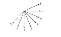
- FIG. 1A shows the conventional H.264 standard. It is a figure which shows an example of the relationship between the object block and reference pixel to which the intra prediction estimation according to H.264 / AVC standard is applied. In addition, FIG. It is a figure which shows the prediction direction contained in the intra prediction mode set according to H.264 / AVC standard.
- the target block 10 of 4 ⁇ 4 pixels is predicted by extrapolating 13 reference pixels 20 located above and to the left of the target block 10 to be predicted.
- a prediction block corresponding to the target block 10 is generated.
- one direction prediction mode is selected from the eight direction prediction modes indicating each of the eight extrapolation directions.
- the DC prediction mode may be selected. In the DC prediction mode, the average value of the reference pixels 20 is used to predict the target block 10.
- the prediction mode to be used for prediction is selected for each macroblock among a plurality of prediction modes, and the encoded target block is encoded by entropy coding together with information related to the selected prediction mode. Compressed and transmitted.
- an estimated value is predicted based on a rule determined in advance by the standard as information related to the selected prediction mode. For example, H.M.
- the estimated value of the intra prediction mode is a number with a smaller number indicating the prediction method among the intra prediction modes of surrounding blocks that have already been encoded. It has been decided.
- the flag indicating the same is transmitted.
- the information to be encoded is transmitted. For example, when the estimated value of the intra prediction mode and the prediction mode actually selected at the time of encoding are the same, only the flag is transmitted. On the other hand, if different, information for restoring the selected prediction mode is transmitted.
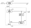
- Figure 2 shows the conventional H.264.
- 2 is a diagram illustrating an example of a detailed configuration of a setting unit 510 that estimates a prediction mode and sets a coding value of a prediction mode, among the configurations of an image encoding device according to the H.264 / AVC standard.
- FIG. 3 shows the conventional H.264 format. It is a figure which shows an example of a detailed structure of the decompression
- the setting unit 510 receives coding mode information SMD indicating a coding mode (intra prediction mode or inter prediction mode).
- a coding mode intra prediction mode or inter prediction mode
- the coding mode information SMD is information IPM indicating the intra prediction mode.
- the coding mode information SMD is position information (motion vector) MV.
- the prediction mode storage memory 511 is a memory for storing the input encoding mode information SMD.
- the prediction mode estimation unit 512 acquires a prediction mode estimation value candidate by a predetermined means from the already encoded encoding mode information input from the prediction mode storage memory 511.
- H.264 for a block size of 4x4 pixels.
- An estimation method of the prediction mode estimation value MPM in the prediction mode estimation units 512 and 624 in the H.264 / AVC standard will be described with reference to FIG. 1A.
- the prediction mode estimation units 512 and 624 perform the intra prediction mode IPM_A of the surrounding block 30 that has already been encoded (or decoded) and the surrounding block 40 with respect to the target block 10 of 4 ⁇ 4 pixels in the encoding and decoding steps. Intra prediction mode IPM_B is acquired. Then, as in Equation 1 below, the mode with the smaller value of IPM_A and IPM_B is set as the prediction mode estimated value MPM.
- MPM Min (PredModeA, PredModeB) (Formula 1)
- PredModeA and PredModeB in Expression 1 indicate index numbers indicating prediction modes used in adjacent blocks, and Min () is a function that outputs one of the smaller indexes.
- the prediction mode estimation unit 512 determines the prediction mode estimation value MPM from the prediction mode estimation value candidates, and outputs the determined prediction mode estimation value MPM.
- the mode information generation unit 515 compares the encoding mode IPM of the encoding target block with the prediction mode estimation value MPM. And when both are the same, the flag which shows that it is the same as the prediction mode estimated value MPM is set to the encoding prediction mode related signal SSMD. On the other hand, if the two are different, the index of the mode signal excluding the corresponding number is output as the encoded prediction mode related signal SSMD.
- a setting method of the mode information generation unit 515 is shown in Expression 2.
- the encoding mode IPM that is an index of the encoding mode of the target block is compared with the prediction mode estimated value MPM calculated by Expression 1. If both are the same, a flag Prev_Intra_Pred_Mode_Flag indicating whether or not the prediction mode estimated value MPM is the same is set to 1, and this flag is output as the encoded prediction mode related signal SSMD.
- Prev_Intra_Pred_Mode_Flag is set to 0 and the size of the index is compared.
- the value of the coding mode IPM is set in the information Rem_Intra_Pred_Mode indicating the coding mode of the target block.
- the index of the encoding mode of the target block is larger than the prediction mode estimated value MPM, a value obtained by subtracting 1 from the IPM value is set in the information Rem_Intra_Pred_Mode indicating the encoding mode of the target block. Then, Prev_Intra_Pred_Mode_Flag and Rem_Intra_Pred_Mode are output as SSMD.
- variable length coding unit 520 entropy codes the coded prediction mode related signal SSMD and outputs it as a bit stream.
- variable length decoding unit 610 outputs the quantized frequency transform coefficient QT and the encoded prediction mode related information SSMD by decoding the input bitstream.
- Coding prediction mode related signal SSMD is input to restoration unit 620, and coding mode information SMD (coding mode MD used for decoding and information or position information (motion vector) MV indicating intra prediction mode IPM). Is output.
- the encoded prediction mode-related signal SSMD is input to the signal determination unit 621, and the flags indicating the same as the prediction mode estimation value MPM in the encoded prediction mode-related signal SSMD are the same.
- the intra prediction mode IPM is output as the prediction mode estimated value MPM. In other cases, the intra prediction mode IPM is set and output from the index information further included in the encoded prediction mode related signal SSMD.
- a setting method of the signal determination unit 621 is shown in Expression 3.
- a flag Prev_Intra_Pred_Mode_Flag indicating whether or not the prediction mode estimated value MPM is the same is read. If this flag is 0, the Prev_Intra_Pred_Mode_Flag is further read to restore the intra prediction mode IPM.
- the prediction mode storage memory 623 is a memory for storing the input coding mode MD and information (intra prediction block size, intra prediction direction, etc.) or position information (motion vector) MV indicating the intra prediction mode IPM.
- the prediction mode estimation unit 624 as shown in Expression 1, from the prediction mode storage memory 623, the already decoded coding mode MD, and information indicating the intra prediction mode IPM or position information (motion vector) MV.
- a plurality of prediction mode estimation value candidates are acquired by means determined in advance.
- the prediction mode estimation unit 624 determines a prediction mode estimation value MPM from among a plurality of prediction mode estimation value candidates, and outputs the determined prediction mode estimation value MPM.
- Non-Patent Document 2 a video encoding method for compressing video data using edge detection has also been proposed, and edge detection may be included in the encoding device and the decoding device.
- a prediction block corresponding to the target block 10 is generated by a method predicted by extrapolating the reference pixel 20 based on an angle obtained by edge detection.
- the In Non-Patent Document 2 the presence / absence of edge detection is replaced with a DC prediction mode that uses the average value of the reference pixels 20. That is, the indexes of the intra prediction mode IPM indicating the DC prediction and the edge prediction are the same, and when a certain condition is satisfied as a result of the edge detection, a prediction block is generated based on the angle obtained by the edge detection. On the other hand, when a certain condition is not satisfied, a prediction block is generated using an average value. Here, whether the magnitude of the edge detected vector exceeds a certain value is used as the certain condition.
- the candidate prediction mode is a prediction mode used for encoding the surrounding blocks of the target block.
- the prediction mode estimation unit 512 and 624 the prediction mode estimation value having a smaller number of prediction mode candidate mode numbers (number shown in FIG. 1B and number 2 showing average value prediction (DC prediction mode)) is selected. Is done.
- the estimated prediction mode of the target block 10 matches one of the prediction modes of the surrounding blocks 30 and 40.
- the edge prediction mode and the DC prediction mode are represented by one code as in Non-Patent Document 2
- the prediction modes of the surrounding blocks 30 and 40 are used as DC prediction or edge prediction. Cannot be expressed, and when the prediction mode of the target block 10 is the edge prediction mode, it is difficult to match the estimated prediction mode. That is, the code amount of the information indicating the prediction mode to be transmitted to the decoder side becomes large.
- the present invention has been made to solve the above-described problems, and encodes image data and video data so that higher encoding efficiency is achieved and a large amount of processing is not required. It is an object of the present invention to provide an image encoding method and an image decoding method for decoding encoded image and video data.
- the image decoding method is a method of decoding encoded image data generated by encoding image data for each block in accordance with prediction based on a prediction mode.
- the image decoding method includes a restoration step of restoring a selected prediction mode that is a prediction mode used for prediction at the time of encoding, based on mode information indicating an estimation result of a prediction mode executed at the time of encoding; And a decoding step of generating a decoded block by decoding a target block of the encoded image data in accordance with prediction based on the selected prediction mode.
- the restoration step includes: a first prediction mode estimation step that determines one prediction mode as a first estimated prediction mode from a plurality of prediction modes; and one different from the first estimated prediction mode from a plurality of prediction modes. Based on the second prediction mode estimation step for determining the prediction mode as the second estimated prediction mode, the mode information, the first estimated prediction mode, and the second estimated prediction mode, the selected prediction mode is determined.
- a prediction mode restoration step of restoring is performed.
- the mode information may include at least flag information indicating a comparison result between the selected prediction mode and the first and second estimated prediction modes.
- the flag information indicates that the selected prediction mode and the first estimated prediction mode match
- the first estimated prediction mode is determined as the selected prediction mode.
- the flag information indicates that the selected prediction mode and the second estimated prediction mode match
- the second estimated prediction mode is determined as the selected prediction mode
- the flag information is When indicating that the selected prediction mode and the first and second estimated prediction modes do not match, the selected prediction mode is determined based on information for specifying the selected prediction mode further included in the mode information. It may be restored.
- the mode information is flag information indicating that the prediction mode used for prediction at the time of encoding matches the prediction mode estimated at the time of encoding, or the flag information is used for prediction at the time of encoding.
- the prediction mode restoration step first decodes first flag information corresponding to the first estimated prediction mode, and the first flag information is used for prediction at the time of encoding.
- the first estimated prediction mode is determined as the selected prediction mode, and the first flag information is When indicating that the prediction mode used for prediction and the prediction mode estimated at the time of encoding do not match, the second flag information corresponding to the second estimated prediction mode is decoded, and the second flag information is Sign When the prediction mode used for prediction at the time and the prediction mode estimated at the time of encoding match, the second estimated prediction mode is determined as the selected prediction mode, and the second flag information is When the prediction mode used for prediction at the time of encoding indicates that the prediction mode estimated at the time of encoding does not match, the selection mode encoding information is decoded, and the selection mode encoding information, the estimated prediction mode, and The selection prediction mode may be restored by comparing the sizes of.
- any one of the first estimated prediction mode and the second estimated prediction mode may be a mode indicating DC / edge prediction.
- the prediction mode having the smallest index number is determined as the first prediction mode among the selected prediction modes of a plurality of blocks adjacent to the target block and already decoded. May be.
- the second estimated prediction mode when the first estimated prediction mode is a planar mode, the second estimated prediction mode is determined as a DC prediction mode, and the first estimated prediction mode is When the mode is not the planar mode, the second estimated prediction mode may be determined as the planar mode.
- the restoration step includes an edge detection step for detecting an edge in the already generated decoded block, and whether the DC / edge prediction mode indicates DC prediction based on the edge detected in the edge detection step, or an edge And a DC / edge prediction determination step for determining whether to indicate prediction.
- first estimated prediction mode or the second estimated prediction mode may be estimated based on the edge direction detected in the edge detection step.
- the image encoding method is a method for encoding image data for each block.
- the image encoding method includes an encoding step of encoding a target block of the image data according to prediction based on a selected prediction mode selected from a plurality of predetermined prediction mode candidates.
- a second prediction mode estimation step for determining one prediction mode different from the first estimation prediction mode as a second estimation prediction mode from the prediction mode, and mode information for restoring the selected prediction mode,
- the output step includes a mode information generation step of generating the mode information based on the first estimated prediction mode, the second estimated prediction mode, and the selected prediction mode.
- the mode information generation step when the selected prediction mode matches one of the first and second estimated prediction modes, flag information indicating which one matches is generated as the mode information, If the selected prediction mode does not match either of the first and second estimated prediction modes, flag information indicating that they do not match and information specifying the selected prediction mode is generated as the mode information. Also good.
- the mode information generation step first, the first estimated prediction mode and the selected prediction mode are compared, and first flag information indicating whether or not they match is generated as the mode information.
- the second estimated prediction mode and the selected prediction mode are further compared, and the second flag information indicating whether or not they match is the mode information.
- the selected prediction mode information is generated as the mode information based on the selected prediction mode and the estimated prediction mode. May be.
- any one of the first estimated prediction mode and the second estimated prediction mode may be a mode indicating DC / edge prediction.
- the prediction mode having the smallest index number among the selected prediction modes of a plurality of blocks that are adjacent to the target block and have already been encoded is referred to as the first prediction mode. You may decide.
- the second estimated prediction mode when the first estimated prediction mode is a planar mode, the second estimated prediction mode is determined as a DC prediction mode, and the first estimated prediction mode is When the mode is not the planar mode, the second estimated prediction mode may be determined as the planar mode.
- the mode information generation step includes an edge detection step for detecting an edge in the already generated decoded block, and whether the DC / edge prediction mode indicates DC prediction based on the edge detected in the edge detection step.
- DC / edge prediction determination step for determining whether to indicate edge prediction.
- first estimated prediction mode or the second estimated prediction mode may be estimated based on the edge direction detected in the edge detection step.
- the image decoding apparatus decodes encoded image data generated by encoding image data for each block according to prediction based on a prediction mode.
- the image decoding apparatus includes: a restoration unit that restores a selected prediction mode that is a prediction mode used for prediction at the time of encoding based on mode information indicating an estimation result of a prediction mode executed at the time of encoding; A decoding unit that generates a decoded block by decoding a target block of the encoded image data in accordance with prediction based on the selected prediction mode.
- the restoration unit is different from the first estimated prediction mode from a first prediction mode estimation unit that determines one prediction mode as a first estimated prediction mode from a plurality of prediction modes, and a plurality of prediction modes.
- the selected prediction A prediction mode restoration unit for restoring the mode.
- the image encoding device encodes image data for each block.
- the image encoding device includes an encoding unit that encodes a target block of the image data in accordance with prediction based on a selected prediction mode selected from a plurality of predetermined prediction mode candidates.
- a decoding unit that generates a decoded block by decoding the encoded target block; a first prediction mode estimation unit that determines one prediction mode as a first estimated prediction mode from a plurality of prediction modes; A second prediction mode estimation unit that determines one prediction mode different from the first estimation prediction mode as a second estimation prediction mode, and mode information for restoring the selected prediction mode,
- an output unit for outputting together with the encoded target block.
- the output unit includes a mode information generation unit that generates the mode information based on the first estimated prediction mode, the second estimated prediction mode, and the selected prediction mode.
- a program causes a computer to decode encoded image data generated by encoding image data for each block according to prediction based on a prediction mode.
- the program restores the selected prediction mode, which is the prediction mode used for prediction at the time of encoding, based on mode information indicating the estimation result of the prediction mode executed at the time of encoding,
- the computer executes a decoding step of generating a decoded block by decoding a target block of the encoded image data.
- the restoration step is different from the first estimated prediction mode from a first prediction mode estimation step for determining one prediction mode as a first estimated prediction mode from a plurality of prediction modes, and a plurality of prediction modes.
- the selected prediction A prediction mode restoration step for restoring a mode.
- a program causes a computer to encode image data for each block.
- the program is encoded with an encoding step for encoding the target block of the image data according to prediction based on a selected prediction mode selected from a plurality of predetermined prediction mode candidates.
- a decoding step for generating a decoded block by decoding the target block, a first prediction mode estimation step for determining one prediction mode as a first estimated prediction mode from a plurality of prediction modes, and a plurality of prediction modes
- a second prediction mode estimation step for determining one prediction mode different from the first estimated prediction mode as a second estimated prediction mode, and mode information for restoring the selected prediction mode.
- the output step includes a mode information generation step of generating the mode information based on the first estimated prediction mode, the second estimated prediction mode, and the selected prediction mode.
- An integrated circuit decodes encoded image data generated by encoding image data for each block in accordance with prediction based on a prediction mode. Specifically, the integrated circuit, based on the mode information indicating the estimation result of the prediction mode executed at the time of encoding, a restoration unit that restores the selected prediction mode that is the prediction mode used for prediction at the time of encoding; A decoding unit that generates a decoded block by decoding a target block of the encoded image data according to prediction based on the selected prediction mode.
- the restoration unit is different from the first estimated prediction mode from a first prediction mode estimation unit that determines one prediction mode as a first estimated prediction mode from a plurality of prediction modes, and a plurality of prediction modes.
- the selected prediction A prediction mode restoration unit for restoring the mode.
- An integrated circuit encodes image data for each block.
- the integrated circuit includes an encoding unit that encodes the target block of the image data in accordance with prediction based on a selected prediction mode selected from a plurality of predetermined prediction mode candidates, A decoding unit that generates a decoded block by decoding the target block, a first prediction mode estimation unit that determines one prediction mode as a first estimated prediction mode from a plurality of prediction modes, and a plurality of predictions A second prediction mode estimation unit that determines, as a second estimated prediction mode, one prediction mode different from the first estimated prediction mode, and mode information for restoring the selected prediction mode from the mode, the code And an output unit for outputting together with the converted target block.
- the output unit includes a mode information generation unit that generates the mode information based on the first estimated prediction mode, the second estimated prediction mode, and the selected prediction mode.
- the present invention can be realized not only as an image encoding method and an image decoding method, but also as an image encoding device and an image decoding device having respective steps included in the image encoding method and the image decoding method as processing units. You can also Moreover, you may implement
- a communication network such as the Internet.
- the system LSI is an ultra-multifunctional LSI manufactured by integrating a plurality of components on a single chip, and specifically includes a microprocessor, ROM, RAM (Random Access Memory), and the like.
- Computer system is an ultra-multifunctional LSI manufactured by integrating a plurality of components on a single chip, and specifically includes a microprocessor, ROM, RAM (Random Access Memory), and the like.
- the prediction mode estimation value can be predicted more accurately, the code amount of the prediction mode can be reduced and the encoding efficiency can be increased.
- FIG. 1A shows the conventional H.264. It is a figure which shows an example of the relationship between the object block and reference pixel to which the intra prediction estimation according to H.264 / AVC standard is applied.
- FIG. 1B shows conventional H.264. It is a figure which shows the prediction direction contained in the intra prediction mode set according to H.264 / AVC standard.
- FIG. It is a figure which shows an example of a detailed structure of an estimation part among the structures of the image coding apparatus according to H.264 / AVC standard.
- FIG. 2 is a diagram illustrating an example of a detailed configuration of a restoration unit in the configuration of an image decoding device according to the H.264 / AVC standard.
- FIG. 4 is a block diagram illustrating an example of a configuration of the image encoding device according to the first embodiment.
- FIG. 5 is a block diagram illustrating an example of a detailed configuration of an image coding apparatus that performs hybrid coding according to the first embodiment.
- FIG. 6A is a block diagram illustrating an example of a detailed configuration of a setting unit included in the image encoding device according to Embodiment 1.
- FIG. 6B is a block diagram illustrating another example of the detailed configuration of the setting unit included in the image coding device according to Embodiment 1.
- FIG. 7A is a flowchart illustrating an example of the operation of the setting unit included in the image encoding device according to the first embodiment.
- FIG. 7B is a flowchart illustrating another example of the operation of the setting unit included in the image coding apparatus according to Embodiment 1.
- FIG. 8 is a flowchart illustrating still another example of the operation of the setting unit included in the image encoding device according to the first embodiment.
- FIG. 9 is a block diagram illustrating an example of the configuration of the image decoding apparatus according to the second embodiment.
- FIG. 10 is a block diagram illustrating an example of a detailed configuration of the image decoding apparatus according to the second embodiment.
- FIG. 11A is a block diagram illustrating an example of a detailed configuration of a restoration unit included in the image decoding device according to Embodiment 2.
- FIG. 11B is a block diagram illustrating another example of the detailed configuration of the restoration unit included in the image decoding device according to Embodiment 2.
- FIG. 12A is a flowchart illustrating an example of the operation of the restoration unit included in the image decoding device according to the second embodiment.
- FIG. 12B is a flowchart illustrating another example of the operation of the restoration unit included in the image decoding device according to Embodiment 2.
- FIG. 13 is a flowchart illustrating still another example of the operation of the restoration unit included in the image decoding device according to the second embodiment.
- FIG. 14 is a block diagram illustrating an example of a detailed configuration of a setting unit included in the image encoding device according to the third embodiment.
- FIG. 15 is a block diagram illustrating an example of a detailed configuration of a restoration unit included in the image decoding device according to the third embodiment.
- FIG. 16 is a flowchart illustrating an example of the operation of the setting unit included in the image encoding device according to the third embodiment.
- FIG. 17 is a flowchart illustrating an example of the operation of the restoration unit included in the image decoding device according to the third embodiment.
- FIG. 18 is a schematic diagram illustrating an example of an edge detection target in the present embodiment.
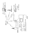
- FIG. 19 is an overall configuration diagram of a content supply system that realizes a content distribution service.
- FIG. 20 is an overall configuration diagram of a digital broadcasting system.
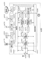
- FIG. 21 is a block diagram illustrating a configuration example of a television.
- FIG. 22 is a block diagram illustrating a configuration example of an information reproducing / recording unit that reads and writes information from and on a recording medium that is an optical disk.
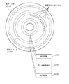
- FIG. 23 is a diagram illustrating a structure example of a recording medium that is an optical disk.
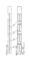
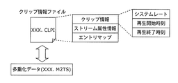
- FIG. 24 is a diagram showing a structure of multiplexed data.
- FIG. 25 is a diagram schematically showing how each stream is multiplexed in the multiplexed data.
- FIG. 26 is a diagram showing in more detail how the video stream is stored in the PES packet sequence.
- FIG. 27 is a diagram illustrating the structure of TS packets and source packets in multiplexed data.
- FIG. 28 shows the data structure of the PMT.
- FIG. 29 is a diagram showing an internal configuration of multiplexed data information.
- FIG. 30 shows the internal structure of stream attribute information.
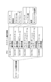
- FIG. 31 is a diagram illustrating steps for identifying video data.
- FIG. 32 is a block diagram illustrating a configuration example of an integrated circuit that implements the moving picture coding method and the moving picture decoding method according to each embodiment.
- FIG. 33 is a diagram illustrating a configuration for switching the driving frequency.
- FIG. 34 is a diagram illustrating steps for identifying video data and switching between driving frequencies.
- FIG. 35 is a diagram illustrating an example of a look-up table in which video data standards are associated with drive frequencies.
- FIG. 36A is a diagram illustrating an example of a configuration for sharing a module of a signal processing unit
- FIG. 36B is a diagram illustrating another example of a configuration for sharing a module of a signal processing unit. is there.
- the image encoding device detects edges included in surrounding blocks located around the target block when encoding image and video data, and performs intra prediction based on the detected edges
- the prediction mode and the DC prediction mode in which intra prediction is performed based on the average value of pixels located in the vicinity are expressed by the same signal (DC / edge prediction mode)
- a plurality of estimated prediction modes are determined, and the mode signal is determined. Is encoded.
- the DC / edge prediction mode is expressed by a short code, thereby reducing the amount of code for the DC / edge prediction mode.
- FIG. 4 is a block diagram illustrating an example of the configuration of the image encoding device 100 according to the present embodiment.
- the image encoding device 100 encodes input image and video data for each block. As illustrated in FIG. 4, the image encoding device 100 includes an encoding unit 110, a decoding unit 120, an output unit 130, and a setting unit 140.
- the encoding unit 110 encodes a target block, which is one of a plurality of blocks constituting image and video data, according to prediction using a selected prediction mode selected from a plurality of prediction mode candidates.
- the plurality of prediction mode candidates are all prediction modes that can be selected when performing prediction. For example, eight prediction modes in advance (see FIG. 1B), DC prediction mode using an average value of reference pixels And an edge prediction mode indicating the direction of the detected edge in the surrounding block.
- the prediction mode is information indicating a reference destination of an image for referring to the predicted image.
- the plurality of prediction mode candidates are not limited to the above example.
- a maximum of 33 direction prediction modes, a DC prediction mode, and a planar mode may be included.
- the number of direction prediction modes can be made variable according to the block size of the target block. For example, 18 directions may be set when the target block is 4 pixels ⁇ 4 pixels, 33 directions may be set when 8 pixels ⁇ 8 pixels to 32 pixels ⁇ 32 pixels, and 2 directions may be set when 64 pixels ⁇ 64 pixels.
- the prana mode is a mode in which each pixel of the target block is predicted by multiplying each pixel value of the surrounding pixels by a weight corresponding to the distance to the prediction pixel and adding the result.
- the weight multiplied by the pixel value of the lower right pixel of the block 40 Is made larger than the weight by which the pixel value of the upper right pixel of the block 30 is multiplied.
- the decoding unit 120 generates a decoded block by decoding the target block encoded by the encoding unit 110.
- the output unit 130 outputs mode information for restoring the selected prediction mode used by the encoding unit 110 together with the target block encoded by the encoding unit 110 as a bit stream.
- the setting unit 140 determines a plurality of estimated prediction modes, and generates mode information for the selected prediction mode, which is a prediction mode used for encoding the target block, using the determined plurality of estimated prediction modes.
- mode information is generated based on two estimation prediction modes.
- the setting unit 140 includes a first prediction mode estimation unit 141, a second prediction mode estimation unit 142, and a mode information generation unit 143.
- the first prediction mode estimation unit 141 determines the estimated prediction mode from the prediction modes of the surrounding blocks that have already been encoded. For example, the method shown in Formula 1 may be used.
- the second prediction mode estimation unit 142 determines an estimated prediction mode other than that determined by the first prediction mode estimation unit 141.
- the mode information generation unit 143 is configured to generate mode information based on the estimated prediction mode set by the first prediction mode estimation unit 141 and the second prediction mode estimation unit 142 and the selected prediction mode selected by the encoding unit 110. Is generated.
- the image coding apparatus 100 determines an estimated prediction mode, and updates the DC / edge prediction mode so as to express it with a short code according to the estimated prediction mode when encoding. It is characterized by.
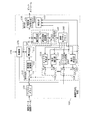
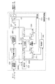
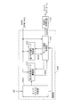
- FIG. 5 is a block diagram illustrating an example of a detailed configuration of the image encoding device 100 according to the present embodiment.
- the image encoding device 100 is an image encoding device that performs hybrid encoding.
- the image encoding device 100 includes an encoding unit 110, a decoding unit 120, an output unit 130, a setting unit 140, a frame memory 150, a reference picture memory 160, a control unit 170, Is provided.
- the same components as those in FIG. 4 are denoted by the same reference numerals.
- the encoding unit 110 includes a subtraction unit 111, a frequency conversion unit 112, a quantization unit 113, an intra prediction mode determination unit 114, a motion detection unit 115, and an intra prediction unit 116. And a motion compensation unit 117 and switches 118 and 119.
- the decoding unit 120 includes an inverse quantization unit 121, an inverse frequency conversion unit 122, and an addition unit 123.
- the output unit 130 includes a variable length encoding unit 131.
- the detailed configuration of the setting unit 140 will be described later with reference to FIGS. 6A and 6B.
- each processing unit will be described along the operation when the image encoding apparatus 100 encodes input video data composed of a plurality of frames.
- Each picture of the input video data is stored in the frame memory 150.
- Each picture is divided into a plurality of blocks and output from the frame memory 150 in units of blocks (for example, in units of macroblocks of 16 horizontal pixels and 16 vertical pixels).
- the input video data may be either a progressive format or an interlace format.
- Each macroblock is encoded in either intra prediction mode or inter prediction mode.
- intra prediction mode either intra prediction mode or inter prediction mode.
- the intra prediction mode (intra frame prediction)
- the macroblock output from the frame memory 150 is input to the intra prediction mode determination unit 114 (at this time, the switch 118 is connected to the terminal “a” by the control unit 170).
- the intra prediction mode determination unit 114 determines how to perform intra prediction on the input macroblock.
- the intra prediction mode determination unit 114 sets an intra prediction block size (one of the following sizes: horizontal 4 pixels ⁇ vertical 4 pixels, horizontal 8 pixels ⁇ ) as an intra prediction mode (IPM: Intra-Prediction Mode). It is necessary to determine 8 vertical pixels, 16 horizontal pixels ⁇ 16 vertical pixels), and the intra prediction direction. For example, the intra prediction mode determination unit 114 determines the intra prediction block size and the intra prediction direction such that the amount of code generated by encoding the target block is smaller than a predetermined threshold. More preferably, the intra prediction mode determination unit 114 determines an intra prediction block size and an intra prediction direction such that the generated code amount is minimized.
- IPM Intra-Prediction Mode
- the target block 10 (4 horizontal pixels ⁇ 4 vertical pixels) illustrated in FIG. 1A may be predicted according to any one of eight predefined intra prediction directions using the reference pixel 20.
- the reference pixel 20 (the diagonally shaded square in FIG. 1A) used for intra prediction has already been encoded and decoded and stored in the reference picture memory 160.
- Information indicating the determined intra prediction mode IPM is output to the intra prediction unit 116 and the setting unit 140.
- the intra prediction unit 116 acquires a reference pixel (intra reference pixel) used for intra prediction from the reference picture memory 160 based on the intra prediction mode IPM determined by the intra prediction mode determination unit 114. Then, the intra prediction unit 116 generates an intra-predicted image IP from the pixel value of the reference pixel, and outputs the generated intra-predicted image IP to the subtraction unit 111 (at this time, the switch 119 is connected to the terminal by the control unit 170). Connected to “a”).
- the subtraction unit 111 receives a macro block (target macro block) of a picture included in the input video data and the intra predicted image IP generated by the intra prediction unit 116 from the frame memory 150. Then, the subtraction unit 111 generates a difference image by calculating a difference (also referred to as a prediction residual) between the target macroblock and the intra predicted image IP, and outputs the generated difference image to the frequency conversion unit 112.
- the frequency conversion unit 112 generates a frequency conversion coefficient by performing frequency conversion such as discrete cosine conversion on the difference image generated by the subtraction unit 111, and outputs the generated frequency conversion coefficient.
- the quantization unit 113 quantizes the frequency conversion coefficient generated by the frequency conversion unit 112, and outputs the quantized frequency conversion coefficient QT.
- the quantization is a process of dividing the frequency conversion coefficient by a predetermined value (quantization step). This quantization step is given by the control unit 170 (the quantization step may be included in the control signal CTL input to the control unit 170).
- the quantized frequency transform coefficient QT is output to the variable length coding unit 131 and the inverse quantization unit 121.
- the inverse quantization unit 121 inversely quantizes the quantized frequency transform coefficient QT and outputs the inversely quantized frequency transform coefficient to the inverse frequency transform unit 122.
- the same quantization step used at the time of quantization by the quantization unit 113 is input from the control unit 170 to the inverse quantization unit 121.
- the inverse frequency transform unit 122 generates a decoded difference image LDD by performing inverse frequency transform on the inversely quantized frequency transform coefficient.
- the inverse frequency conversion unit 122 outputs the generated decoded difference image LDD to the addition unit 123.
- the addition unit 123 generates the decoded image LD by adding the decoded differential image LDD to the intra-predicted image IP (or an inter-predicted image described later in the case of the inter prediction mode) MP.
- the adding unit 123 stores the generated decoded image LD in the reference picture memory 160.
- the decoded image LD stored in the reference picture memory 160 is used as a reference image for later encoding.
- variable-length coding unit 131 performs variable-length coding on the quantized frequency transform coefficient QT input from the quantization unit 113 and receives intra-input from the intra prediction mode determination unit 114 via the setting unit 140.
- Information indicating the prediction mode IPM is processed in the same manner, and a bit stream referred to as an encoded sequence is output. As described above, the detailed configuration of the setting unit 140 will be described later with reference to FIGS. 6A and 6B.
- variable length encoding unit 131 As one of the variable length encoding methods used by the variable length encoding unit 131, the international standard H.264 for encoding moving images is used. There is a context adaptive arithmetic coding method employed in H.264.
- the context adaptive arithmetic coding method is a method of switching a probability table used for arithmetic coding according to target data for variable length coding and data that has already been subjected to variable length coding (context adaptive type). is there.
- the variable length coding unit 131 includes a memory that holds a probability table.
- variable length coding unit 131 may perform variable length coding on the quantized frequency transform coefficient QT using a context adaptive variable length coding method.
- the macroblock output from the frame memory 150 is input to the motion detection unit 115 (at this time, the switch 118 is connected to the terminal “b” by the control unit 170. ).
- the motion detection unit 115 receives motion information (position information (motion vector) for a reference picture (a reconstructed picture held in the reference picture memory 160, which is different from the picture to be encoded) of the input macroblock. )) Is detected.
- position information (motion vector) shown below is generally detected as motion information. That is, it is position information (motion vector) having the minimum difference value between the target block to be encoded and the predicted image and the minimum sum of the weights of the code amount of the position information (motion vector).
- the detected position information (motion vector) is output to the motion compensation unit 117 and the setting unit 140 as motion information for the target block.
- the motion compensation unit 117 acquires a reference pixel (inter reference pixel) used for inter prediction from the reference picture memory 160 based on the motion information (position information (motion vector)) detected by the motion detection unit 115. Then, the motion compensation unit 117 generates the inter predicted image MP and outputs the generated inter predicted image MP to the subtracting unit 111 (at this time, the switch 119 is connected to the terminal “b” by the control unit 170). .
- inter reference pixel used for inter prediction from the reference picture memory 160 based on the motion information (position information (motion vector)) detected by the motion detection unit 115. Then, the motion compensation unit 117 generates the inter predicted image MP and outputs the generated inter predicted image MP to the subtracting unit 111 (at this time, the switch 119 is connected to the terminal “b” by the control unit 170).
- the processing executed by the subtraction unit 111, the frequency conversion unit 112, the quantization unit 113, the inverse quantization unit 121, the inverse frequency conversion unit 122, and the addition unit 123 is the process described in the case of intra prediction. Is the same. Therefore, description of these processes is omitted here.
- variable length coding unit 131 performs variable length coding on the quantized frequency transform coefficient QT input from the quantization unit 113, and also indicates information indicating the coding mode MD output from the setting unit 140 and intra prediction. Variable length coding is performed on mode information including mode IPM or information indicating motion information (position information (motion vector)) MV, and a bit stream is output. As described above, the detailed configuration of the setting unit 140 will be described later with reference to FIGS. 6A and 6B.
- variable length encoding unit 131 when the variable length encoding unit 131 encodes motion information (position information (motion vector)) MV using context adaptive arithmetic encoding, the variable length encoding unit 131 stores a probability table. Is provided.
- the mode information reproduces the prediction executed on the encoder (image encoding device 100) side in the process of encoding the video data on the decoder (for example, image decoding device 300 (see FIG. 9) described later) side.
- the mode information defines for each macroblock which coding mode, that is, whether intra prediction or inter prediction is applied.
- the mode information includes information on how the macroblock is subdivided. H. According to H.264 / AVC, a 16 ⁇ 16 pixel macroblock may be further subdivided into 8 ⁇ 8 or 4 ⁇ 4 pixel blocks, for example, in the case of intra prediction.
- the mode information further identifies a set of position information (position information (motion vector)) used for motion compensation or an intra prediction mode applied to intra-predict the target block. Information to be included.
- control unit 170 selects the encoding mode (intra prediction mode or inter prediction mode).
- control unit 170 may generate an inter prediction image IP generated based on the intra prediction mode IPM and the decoded image LD, or an inter prediction image generated based on the position information (motion vector) MV and the decoded image LD.
- the encoding mode is selected by comparing the MP and the target block image IMG.
- control unit 170 selects an encoding mode having a value that minimizes the sum of weights of the generated bit amount and encoding distortion.
- control unit 170 may A cost function using the H.264 standard bit rate and encoding distortion may be used to determine the best prediction mode for encoding the target block. For each prediction mode, the difference image is orthogonally transformed, quantized, and variable-length coded. Then, the bit rate and coding distortion are calculated for each prediction mode.
- cost function for example, a Lagrangian cost function J represented by Expression 4 is used.
- R is a bit rate used to encode the difference image (also referred to as prediction residual) and prediction mode information.
- D is the coding distortion.
- ⁇ is a Lagrange multiplier calculated according to the quantization parameter QP selected for encoding.
- the control unit 170 selects the prediction mode in which the cost function J is the lowest as the prediction mode for predicting the target block.
- control unit 170 includes a memory that temporarily stores the cost function J in order to select an optimal prediction mode.
- FIG. 6A and 6B are diagrams illustrating an example of a detailed configuration of the setting unit 140 according to the present embodiment.
- the setting unit 140 includes a first prediction mode estimation unit 141, a second prediction mode estimation unit 142, and a mode information generation unit 143.
- the same components as those in FIG. 4 are denoted by the same reference numerals.
- the first prediction mode estimation unit 141 shown in FIG. 6A includes a prediction mode storage memory 211 and a first prediction mode estimation deriving unit 212.
- the setting unit 140 receives coding mode information SMD indicating the coding mode (intra prediction mode or inter prediction mode) selected by the control unit 170.
- the coding mode information SMD is information (intra prediction block size, intra prediction direction, etc.) indicating the intra prediction mode IPM.
- the coding mode information SMD is position information (motion vector) MV.
- the prediction mode storage memory 211 is a memory for storing input coding mode information SMD.
- the first prediction mode estimation deriving unit 212 is a first estimated prediction that is a result of estimating the prediction mode from the prediction mode storage memory 211 by using a predetermined means from the already encoded coding mode information.
- the mode MPM is derived and output to the mode information generation unit 143.
- the prediction mode of an already encoded block adjacent to the top of the encoding target block, and the encoding target block Among the prediction modes of blocks that have already been encoded adjacent to the left part the one with the smaller index number corresponding to the prediction mode may be used as the first estimated prediction mode MPM.
- the prediction mode of the block adjacent to the upper left or upper right of the encoding target block may be further referred to, and the one having a high appearance frequency may be derived as the first estimated prediction mode MPM.
- the derivation of the first estimated prediction mode MPM is not limited to the above-described method as long as it is a derivation method of the prediction mode that is estimated to be generated most.
- the directional prediction mode closest to the estimated prediction mode selected by the above method is selected from the directional prediction modes that can be selected in the encoding target block.
- the first estimated prediction mode MPM may be used.
- the second prediction mode estimation unit 142 acquires a control signal from the mode information generation unit 143, and obtains the second estimated prediction mode SPM, which is an estimated value of the second prediction mode set by a predetermined method, as mode information.
- the data is output to the generation unit 143.
- the second estimated prediction mode SPM to DC / edge prediction, it is possible to efficiently encode and decode one mode information meaning a plurality of prediction modes.
- the mode information generation unit 143 generates mode information based on the first estimated prediction mode MPM, the second estimated prediction mode SPM, and the selected prediction mode SMD selected by the encoding unit 110, and performs encoded prediction.
- the mode-related signal SSMD is output to the variable length coding unit 131.
- the variable length encoding unit 131 performs variable length encoding processing on the encoded prediction mode-related signal SSMD and outputs it as a bit stream.
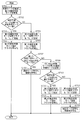
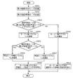
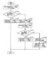
- FIG. 7A is a flowchart illustrating an example of operations of the first prediction mode estimation unit 141, the second prediction mode estimation unit 142, and the mode information generation unit 143 illustrated in FIG. 6A. Generation of mode information in the mode information generation unit 143 will be described in more detail with reference to FIG. 7A.
- the mode information generation unit 143 acquires the first estimated prediction mode MPM derived by the first prediction mode estimation unit 141 (step S701).
- the selected prediction mode SMD matches the first estimated prediction mode MPM (YES in step S702)
- the first estimated prediction mode designation flag is set to “1 (indicates matching)” (step S703)
- the variable-length encoding unit 131 encodes the first estimated prediction mode designation flag as the encoded prediction mode-related signal SSMD (step S704).
- the selected prediction mode SMD does not match the first estimated prediction mode MPM (NO in step S702), “0 (indicates no match)” is set in the first estimated prediction mode designation flag (step S705).
- the first estimated prediction mode designation flag is encoded by the variable length encoding unit 131 as the encoded prediction mode related signal SSMD (step S706).
- the selection prediction mode SMD is set as selection mode encoding information, and the encoding prediction mode related information is added to the flag information.
- the signal SSMD is encoded by the variable length encoding unit 131 (step S708).
- the mode information generation unit 143 outputs a control signal to the second prediction mode estimation unit 142.
- the second prediction mode estimation unit 142 sets the DC / edge prediction mode as the second estimation prediction mode SPM and outputs it to the mode information generation unit 143 (step S709).
- step S710 when the selected prediction mode SMD matches the second estimated prediction mode SPM (YES in step S710), “1 (indicates that they match)” is set in the second estimated prediction mode designation flag (step S710).
- step S710 the second estimated prediction mode designation flag is encoded by the variable length encoding unit 131 as the encoded prediction mode related signal SSMD (step S712).
- the selected prediction mode SMD does not match the second estimated prediction mode SPM (NO in step S710), “0 (indicates no match)” is set in the second estimated prediction mode designation flag (step S713).
- the second estimated prediction mode designation flag is encoded by the variable length encoding unit 131 as the encoded prediction mode related signal SSMD (step S714).
- the selection prediction mode SMD is set as selection mode encoding information, and is encoded by the variable length encoding unit 131 as the encoding prediction mode related signal SSMD in addition to the flag information (step S715).
- the selection prediction mode SMD was encoded as selection mode encoding information as it is here when it does not correspond with 1st estimation prediction mode MPM and 2nd estimation prediction mode SPM, it is not restricted to this.
- the number of estimated prediction modes (FIGS. 6A and 7A) In the example, a value obtained by subtracting 2) at the maximum may be encoded as selection mode encoding information. Thereby, the code amount can be further reduced.
- the MPM index number of the first estimated prediction mode is MPM
- the index number of the selected prediction mode SMD is SMD
- the first estimated prediction mode designation flag is MPMF
- the second estimated prediction mode designation flag is SPMF
- DC / edge prediction is DCEDGE
- the above-described flow can be expressed as shown in Equation 5, for example.
- the index number corresponding to the DC / prediction mode may be “0”.
- the index number of the second estimated prediction mode SPM is always “0”, when encoding the index number of the selected prediction mode SMD, a value obtained by subtracting at least 1 should be encoded. Thus, the code amount can be further reduced.
- Equation 6 An example written in the same manner as Equation 5 is shown in Equation 6.
- FIG. 6B a configuration in which the functions of the first prediction mode estimation unit 141 and the second prediction mode estimation unit 142 are replaced may be employed. This configuration is shown in FIG. 6B.
- the second prediction mode estimation unit 142 illustrated in FIG. 6B includes a prediction mode storage memory 211 and a second prediction mode estimation deriving unit 213.
- the first prediction mode estimation unit 141 outputs the first estimated prediction mode MPM, which is an estimated value of the first prediction mode set by a predetermined method, to the mode information generation unit 143.
- the first estimated prediction mode MPM to DC / edge prediction, it is possible to efficiently encode / decode one mode information meaning a plurality of prediction modes.
- the second prediction mode estimation unit 142 receives the control signal from the mode information generation unit 143, and selects the prediction mode from the prediction mode storage memory 211 by using a predetermined means from the already encoded coding mode information.
- a second estimated prediction mode SPM that is an estimation result is derived and output to the mode information generation unit 143.
- the method for deriving the second estimated prediction mode SPM is the same as the method for deriving the first estimated prediction mode MPM in FIG. 6A, but the first estimated prediction mode MPM is acquired and the second estimation is performed. You may determine so that prediction mode SPM and 1st estimation prediction mode MPM may not overlap. For example, after the first estimation mode MPM is excluded from the candidate modes, the second estimation prediction mode SPM is determined by a predetermined method, whereby different candidates for the first and second estimation prediction modes are used. Can be set, and the amount of codes can be reduced.
- the mode information generation unit 143 generates mode information based on the first estimated prediction mode MPM, the second estimated prediction mode SPM, and the selected prediction mode SMD selected by the encoding unit 110, and performs encoded prediction.
- the mode-related signal SSMD is output to the variable length coding unit 131.
- the variable length encoding unit 131 performs variable length encoding processing on the encoded prediction mode-related signal SSMD and outputs it as a bit stream.
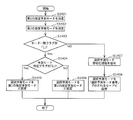
- FIG. 7B is a flowchart illustrating an example of operations of the first prediction mode estimation unit 141, the second prediction mode estimation unit 142, and the mode information generation unit 143 illustrated in FIG. 6B.
- the mode information generation unit 143 sets the DC / edge prediction mode as the first estimated prediction mode MPM in the first prediction mode estimation unit 141, and acquires the set first estimated prediction mode MPM (step) S801).
- the selected prediction mode SMD matches the first estimated prediction mode MPM (YES in step S802), “1 (indicates that they match)” is set in the first estimated prediction mode designation flag (step S803),
- the variable length encoding unit 131 encodes the first estimated prediction mode designation flag as the encoded prediction mode related signal SSMD (step S804).
- the selected prediction mode SMD does not match the first estimated prediction mode MPM (NO in step S802), “0 (indicates no match)” is set in the first estimated prediction mode designation flag (step S805).
- the first estimated prediction mode designation flag is encoded by the variable length encoding unit 131 as the encoded prediction mode related signal SSMD (step S806).
- the mode information generation unit 143 outputs a control signal to the second prediction mode estimation unit 142.
- the second prediction mode estimation unit 142 derives the second estimation prediction mode SPM by a predetermined method, and outputs it to the mode information generation unit 143 (step S807).
- step S808 when the selected prediction mode SMD matches the second estimated prediction mode SPM (YES in step S808), “1 (indicates that they match)” is set to the second estimated prediction mode designation flag (step S808).
- step S7809 the second estimated prediction mode designation flag is encoded by the variable length encoding unit 131 as the encoded prediction mode related signal SSMD (step S810).
- the selected prediction mode SMD does not match the second estimated prediction mode SPM (NO in step S808), “0 (indicates no match)” is set in the second estimated prediction mode designation flag (step S811). ),
- the second estimated prediction mode designation flag is encoded by the variable length encoding unit 131 as the encoded prediction mode related signal SSMD (step S812).
- the selection prediction mode SMD is set as selection mode encoding information, and is encoded by the variable length encoding unit 131 as an encoding prediction mode related signal SSMD in addition to the flag information (step S813).
- the selection prediction mode SMD was encoded as selection mode encoding information as it is here when it does not correspond with 1st estimation prediction mode MPM and 2nd estimation prediction mode SPM, it is not restricted to this.
- Expression 2 there is no number that matches the estimated prediction mode, and therefore when the index number of the selected prediction mode SMD exceeds the index number of the estimated prediction mode, the number of estimated prediction modes (FIGS. 6B and 7B).
- a value obtained by subtracting 2) at the maximum may be encoded as selection mode encoding information. Thereby, the code amount can be further reduced.
- Equation 7 An example written in the same manner as Equations 5 and 6 is shown in Equation 7.
- the index number corresponding to the DC / prediction mode may be set to “0” as in the case of FIG. 7A.
- the index number of the first estimated prediction mode SPM is always “0”, when encoding the index number of the selected prediction mode SMD, it is only necessary to encode a value subtracted by at least 1. Further, the code amount can be reduced.
- Equation 8 An example written in the same manner as Equation 7 is shown in Equation 8.
- the image quality can be improved not only by reducing the prediction mode code amount but also by improving the prediction performance.
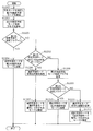
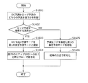
- FIG. 8 is a flowchart according to a modification of the first embodiment.
- the following description is an example in which the setting unit 140 illustrated in FIG. 6A executes the processing in FIG. 8, but is not limited thereto.
- the “mode match flag” appearing in the flowchart of FIG. 8 is that the selected prediction mode matches one of the first and second estimated prediction modes (“1” is set), or matches both. This is a 1-bit flag indicating that no ("0" is set).
- the “prediction mode identification flag” means that the selected prediction mode matches the first estimated prediction mode (“0” is set), or the selected prediction mode matches the second estimated prediction mode ( 1-bit flag indicating that "1" is set).
- the mode match flag and the prediction mode identification flag are encoded as the encoded prediction mode related signal SSMD.
- the first prediction mode estimation unit 141 determines a first estimation prediction mode (S901).
- the method described above can be used as the method of determining the first estimated prediction mode.
- the prediction mode with the smallest index number is determined as the first prediction mode among the prediction modes of a plurality of blocks that are adjacent to the encoding target block and have already been encoded.
- the second prediction mode estimation unit 142 determines a second estimation prediction mode (S902).
- the second estimated prediction mode is different from the first estimated prediction mode.
- the determination method of 2nd estimation prediction mode is not specifically limited, For example, it can determine with the following methods.
- the second prediction mode estimation unit 142 determines whether or not the first estimation prediction mode is the planar mode. If the first estimated prediction mode is the planar mode, the second prediction mode estimation unit 142 determines the second estimated prediction mode as the DC mode. On the other hand, if the first estimated prediction mode is not the planar mode, the second prediction mode estimating unit 142 determines the second estimated prediction mode to be the planar mode.
- the mode information generation unit 143 determines whether or not the selected prediction mode matches any of the first and second estimated prediction modes (S903). If it matches either (Yes in S903), the mode information generation unit 143 sets “1 (indicates that either matches)” to the mode match flag (S904).
- the mode information generation unit 143 determines whether or not the selected prediction mode matches the first estimated prediction mode (S905). Needless to say, it may be determined in step S905 whether or not the selected prediction mode and the second estimated prediction mode match.
- the mode information generation unit 143 When the selected prediction mode and the first estimated prediction mode match (Yes in S905), the mode information generation unit 143 indicates “0 (matches the first estimated prediction mode) in the prediction mode identification flag. ) ”Is set (S906). On the other hand, if they do not match (No in S905), the mode information generation unit 143 sets “1 (indicates that the second estimated prediction mode matches)” to the prediction mode identification flag (S907).
- the mode match flag and prediction mode identification flag set in steps S904 to S907 are encoded by the variable length encoding unit 131 as the encoded prediction mode related signal SSMD (S908).
- step S903 when the selected prediction mode does not match either of the first and second estimated prediction modes (No in S903), the mode information generation unit 143 sets “0 (does not match either) in the mode match flag. ")" Is set (S909). Then, the information specifying the mode match flag and the selected prediction mode set in S909 is encoded by the variable length encoding unit 131 as the encoded prediction mode related signal SSMD (S910).
- the information for specifying the selected prediction mode corresponds to, for example, the selection mode encoding information that can be determined by Equation 5, but if the information can specify the selected prediction mode on the decoding side, It is not limited.
- the image encoding device, the image decoding device, and the corresponding method of the present invention have been described based on the embodiments.
- the present invention is not limited to these embodiments. Unless it deviates from the meaning of this invention, what made the various deformation
- the mode number assigned to each prediction mode may be dynamically changed according to the appearance frequency of the prediction mode. Specifically, a smaller mode number may be assigned to a prediction mode with a higher appearance frequency.
- the present invention relates to H.264. It is not limited to the H.264 video coding standard, but limited to the above-described conventional intra prediction mode prediction values and position information (motion vector) prediction values such as the intra prediction mode (edge prediction mode) using the edge direction of Non-Patent Document 2. Not. In fact, the inventive prediction mode estimation method may be used in any block-based video encoder.
- the edge detection unit in the prediction mode estimation method of the present invention may be shared with some functions of the video encoding method. For example, by applying the present invention to a video encoding method including an edge prediction mode, the edge detection unit can be used together, and resources can be used effectively.
- the present invention is not limited to video encoding applications, and may be used for block-based still image encoding.
- the present invention can be realized not only as an image encoding device and these methods, but also as a program for causing a computer to execute each of the image encoding methods of the present embodiment. . Further, it may be realized as a computer-readable recording medium such as a CD-ROM for recording the program. Furthermore, it may be realized as information, data, or a signal indicating the program. These programs, information, data, and signals may be distributed via a communication network such as the Internet.
- DC prediction and edge prediction are handled as the same prediction index number.
- the present invention is not limited to this point. Instead, the same processing is performed even when the prediction mode in which prediction pixels are generated by a method different from directional prediction and edge prediction are treated as the same prediction index. By performing the above, it becomes possible to efficiently encode and decode the prediction mode.
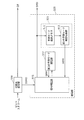
- FIG. 9 is a block diagram showing an example of the configuration of the image decoding apparatus 300 according to the present embodiment.
- the image decoding apparatus 300 decodes the encoded image data generated by encoding the image data for each block according to the prediction using the prediction mode. As illustrated in FIG. 9, the image decoding device 300 includes a decoding unit 310 and a restoration unit 320.
- the decoding unit 310 generates a decoded block by decoding a target block which is one of a plurality of blocks constituting the encoded image data according to the prediction using the selected prediction mode restored by the restoration unit 320.
- the generated decoded block is output as image and video data.
- the plurality of prediction mode candidates are all prediction modes that can be selected when performing prediction, as in the encoder side, and include, for example, eight directional prediction modes, a DC prediction mode, an edge prediction mode, and the like. Contains. Or you may include the 33 direction prediction modes, DC prediction mode, and planar mode which were already demonstrated.
- the restoration unit 320 restores the selected prediction mode from a plurality of prediction mode candidates based on the mode information for restoring the prediction mode selected at the time of encoding.
- the mode information is information indicating the selection result of the prediction mode executed at the time of encoding.
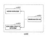
- the restoration unit 320 includes a first prediction mode estimation unit 321, a second prediction mode estimation unit 322, and a signal determination unit 323.
- the first prediction mode estimation unit 321 and the second prediction mode estimation unit 322 are examples of the prediction mode restoration unit according to the present invention, and one of the DC / edge prediction modes is set as the estimated prediction mode, and the DC -It is possible to restore a bitstream with a reduced code amount for the edge prediction mode.
- the image decoding apparatus 300 is characterized by decoding a bitstream in which the code amount of the prediction mode is reduced by estimating a plurality of prediction modes. That is, the image decoding apparatus 300 according to the present embodiment is characterized in that the prediction mode is restored by estimating at least two or more prediction modes.
- FIG. 10 is a block diagram illustrating an example of a detailed configuration of the image decoding apparatus 300 according to the present embodiment.
- the image decoding apparatus 300 includes a decoding unit 310, a restoration unit 320, a variable length decoding unit 330, and a control unit 340.
- the decoding unit 310 includes an inverse quantization unit 311, an inverse frequency conversion unit 312, an addition unit 313, a frame memory 314, a switch 315, an intra prediction unit 316, and motion compensation. A unit 317 and a switch 318.
- the detailed configuration of the restoration unit 320 will be described later with reference to FIGS. 11A and 11B.
- the image decoding apparatus 300 decodes encoded video data including a prediction residual as either intra or interframe predictive encoded blocks for each block, and outputs the decoded data as video data or image data.
- the variable length decoding unit 330 performs variable length decoding on the bitstream based on a predetermined means, and outputs a quantized frequency transform coefficient QT and an encoded prediction mode related signal SSMD.
- the restoration unit 320 receives the encoded prediction mode related signal SSMD and the already decoded image signal LD, and outputs information indicating the encoding mode MD and the intra prediction mode IPM or position information (motion vector) MV. To do. As described above, the detailed configuration of the restoration unit 320 will be described later with reference to FIGS. 11A and 11B.
- the encoding mode MD is input to the control unit 340.
- Information indicating the intra prediction mode IPM or the position information (motion vector) MV is input to the switch 315.
- the quantized frequency transform coefficient QT is input to the inverse quantization unit 311.
- the control unit 340 controls the switches 315 and 318 based on the encoding mode MD.
- the switch 315 When the encoding mode MD indicates intra prediction encoding, the switch 315 is connected to the terminal “a”, and information indicating the intra prediction mode IPM is input to the intra prediction unit 316.
- the switch 315 When the encoding mode MD indicates inter prediction encoding, the switch 315 is connected to the terminal “b”, and the position information (motion vector) MV is input to the motion compensation unit 317.
- the switches 315 and 318 are connected to the terminal “a”.
- Information indicating the intra prediction mode IPM is input to the intra prediction unit 316, and the quantized frequency transform coefficient QT is input to the inverse quantization unit 311.
- the quantized frequency transform coefficient QT corresponds to a prediction residual encoded by an encoder (for example, the image encoding device 100).
- the intra prediction unit 316 acquires an intra prediction reference pixel from the frame memory 314 based on the input intra prediction mode, generates an intra predicted image (prediction block), and outputs the intra prediction image to the addition unit 313. To do.
- the inverse quantization unit 311 inversely quantizes the quantized frequency transform coefficient QT and outputs the inversely quantized frequency transform coefficient to the inverse frequency transform unit 312. Then, the inverse frequency transform unit 312 generates a decoded decoded difference image LDD by performing inverse frequency transform on the inversely quantized frequency transform coefficient.
- the inverse frequency conversion unit 312 outputs the generated decoded difference image LDD to the addition unit 313.
- the addition unit 313 generates a decoded image LD by adding the decoded difference image LDD and the intra predicted image IP.
- the generated decoded image LD is stored in the frame memory 314. Note that the decoded image LD stored in the frame memory 314 is used as a reference picture in later decoding.
- the decoded image LD is output so as to form decoded video data.
- the switches 315 and 316 are connected to the terminal “b”.
- Information indicating the position information (motion vector) MV is input to the motion compensation unit 317, and the quantization frequency transform coefficient QT is input to the inverse quantization unit 311.
- the motion compensation unit 317 acquires a reference pixel from the frame memory 314 based on the input position information (motion vector) MV, generates a predicted picture, and outputs the predicted picture to the addition unit 313.
- the processes of the inverse quantization unit 311, the inverse frequency conversion unit 312, and the addition unit 313 are the same as those described for the intra prediction block.
- the decoded image LD is stored in the frame memory 314.
- the decoded image LD stored in the frame memory 314 is used as a reference picture in later decoding.
- the decoded image LD is output so as to form decoded video data.
- FIG. 11A is a diagram illustrating an example of a detailed configuration of the restoration unit 320 according to the present embodiment.
- the restoration unit 320 includes a first prediction mode estimation unit 321, a second prediction mode estimation unit 322, and a signal determination unit 323.
- the first prediction mode estimation unit 321 includes a prediction mode storage memory 411 and a first prediction mode estimation deriving unit 412.
- the reconstruction unit 320 receives the encoded prediction mode related signal SSMD, and outputs information indicating the encoding mode MD and the intra prediction mode IPM or the position information (motion vector) MV as the encoding mode information SMD.
- the prediction mode storage memory 411 is a memory for storing the input already decoded coding mode information SMD.
- the first prediction mode estimation deriving unit 412 obtains a first estimated prediction that is a result of estimating a prediction mode by a predetermined means from the encoded mode information SMD already decoded from the prediction mode storage memory 411.
- the mode MPM is derived and output to the signal determination unit 323.
- the prediction mode of the already decoded block adjacent to the upper part of the decoding target block and the left part of the decoding target block Of the prediction modes of adjacent blocks that have already been decoded one having a smaller index number corresponding to the prediction mode may be used as the first estimated prediction mode MPM.
- the prediction mode of the block adjacent to the upper left or upper right of the decoding target block may be further referred to, and the one having a high appearance frequency may be derived as the first estimated prediction mode MPM.
- the derivation of the first estimated prediction mode MPM is not limited to the above-described method as long as it is a derivation method of the prediction mode that is estimated to be generated most.
- this estimation method uses the same method as that used when the bitstream is encoded.
- the directional prediction mode closest to the estimated prediction mode selected by the above method is selected from the directional prediction modes that can be selected in the decoding target block.
- the estimated prediction mode MPM may be used.
- the second prediction mode estimation unit 322 acquires a control signal from the signal determination unit 323, and calculates a second estimated prediction mode SPM that is an estimated value of the second prediction mode set by a predetermined method. Output to H.323.
- the signal determination unit 323 includes a first estimated prediction mode MPM, a second estimated prediction mode SPM, and a coded prediction mode related signal SSMD obtained by variable length decoding the bit stream from the variable length decoding unit 330. Based on this, encoding mode information SMD is generated and output.
- the second estimated prediction mode SPM to DC / edge prediction, it is possible to efficiently encode / decode one mode information meaning a plurality of prediction modes.
- FIG. 12A is a flowchart illustrating an example of operations of the first prediction mode estimation unit 321, the second prediction mode estimation unit 322, and the signal determination unit 323 illustrated in FIG. 11A.
- the decoding of the coding mode information in the signal determination unit 323 will be described in more detail using FIG. 12A.
- the signal determination unit 323 acquires the first estimated prediction mode MPM derived by the first prediction mode estimation unit 321 (step S1201). Next, the signal determination unit 323 obtains the encoded prediction mode related information SSMD and decodes the first estimated prediction mode designation flag (step S1202). If the first estimated prediction mode designation flag is “1” (YES in step S1203), the selected prediction mode SMD is set as the first estimated prediction mode MPM (step S1204) and output.
- step S1203 when the first estimated prediction mode designation flag is “0” (NO in step S1203) and the first estimated prediction mode MPM is the DC / edge prediction mode (YES in step S1205). Subsequently, the selected prediction mode coding information is decoded (step S1206). The mode indicated by the selected prediction mode number obtained by decoding is set as the selected prediction mode SMD (step S1207) and output.
- the second estimated prediction mode designation flag is decoded (step S1208). If the second estimated prediction mode designation flag is “1” (YES in step S1209), the selected prediction mode SMD is set as the second estimated prediction mode SPM (step S1210) and output. When the second estimated prediction mode designation flag is “0” (NO in step S1209), the selected prediction mode encoding information is decoded (step S1211). The mode indicated by the selected prediction mode number obtained by decoding is set as the selected prediction mode SMD (step S1212) and output.
- selection prediction mode SMD was encoded as selection mode encoding information as it was was demonstrated. Not exclusively. For example, since there is no number that matches the estimated prediction mode as shown in Equation 3, if the index number of the selected prediction mode SMD exceeds the index number of the estimated prediction mode, the number of estimated prediction modes (FIGS. 6A and 7A) In the example, encoding can be performed by subtracting a maximum of 2). Therefore, at the time of decoding, a value obtained by adding the number of estimated prediction modes (maximum 2 in FIGS. 11A and 12A) is decoded as selection mode encoding information. As a result, it is possible to decode a bitstream with a further reduced code amount.
- Parse () indicates that the data in () is decoded from the encoded prediction mode related signal SSMD, the index number of the first estimated prediction mode MPM is MPM, the index number of the selected prediction mode SMD is SMD,
- the estimated prediction mode designation flag is MPMF
- the second estimated prediction mode designation flag is SPMF
- the DC / edge prediction index number is DCEDGE
- the selection mode encoding information is REM
- the index number corresponding to the DC / prediction mode may be “0”.
- the index number of the second estimated prediction mode SPM is always “0”, when encoding the index number of the selected prediction mode SMD, a value obtained by subtracting at least 1 should be encoded. .
- a bit stream with a further reduced code amount can be decoded by decoding as a value obtained by adding at least 1 at the time of decoding.
- Equation 10 An example written in the same manner as Equation 9 is shown in Equation 10.
- the second prediction mode estimation unit 322 includes a prediction mode storage memory 411 and a second prediction mode estimation derivation unit 413.
- the reconstruction unit 320 receives the encoded prediction mode related signal SSMD, and outputs information indicating the encoding mode MD and the intra prediction mode IPM or the position information (motion vector) MV as the encoding mode information SMD.
- the prediction mode storage memory 411 is a memory for storing the input already decoded coding mode information SMD.
- the second prediction mode estimation / derivation unit 413 obtains the second estimated prediction that is a result of estimating the prediction mode from the prediction mode storage memory 411 by using a predetermined means from the already decoded coding mode information SMD.
- the mode SPM is derived and output to the signal determination unit 323.
- the method for deriving the second estimated prediction mode SPM is the same as the method for deriving the first estimated prediction mode MPM in FIG. 11A.
- the first estimated prediction mode MPM is acquired and the second estimated prediction mode MPM is obtained. You may determine so that mode SPM and 1st estimation prediction mode MPM may not overlap.
- the second estimated prediction mode SPM is determined by a predetermined method, so that the first and second estimated prediction modes are different. Candidates can be set, and a bitstream with a reduced code amount can be decoded. In this estimation method, the same method as that used when the bitstream is encoded is used.
- the first prediction mode estimation unit 321 gives the signal determination unit 323 a first estimated prediction mode MPM that is an estimated value of the first prediction mode set by a predetermined method. Output.
- the first estimated prediction mode MPM DC / edge prediction it is possible to efficiently encode and decode one mode information meaning a plurality of prediction modes.
- the signal determination unit 323 includes a first estimated prediction mode MPM, a second estimated prediction mode SPM, and a coded prediction mode related signal SSMD obtained by variable length decoding the bit stream from the variable length decoding unit 330. Based on this, encoding mode information SMD is generated and output.
- FIG. 12B is a flowchart illustrating an example of operations of the first prediction mode estimation unit 321, the second prediction mode estimation unit 322, and the signal determination unit 323 illustrated in FIG. 11B. Decoding of the encoding mode information SMD in the signal determination unit 323 will be described in more detail with reference to FIG. 12B.
- the signal determination unit 323 acquires the encoded prediction mode related information SSMD and decodes the first estimated prediction mode designation flag (step S1301). If the first estimated prediction mode designation flag is 1 (YES in step S1302), the selected prediction mode SMD is set as the first estimated prediction mode MPM (step S1303) and output.
- the signal determination unit 323 obtains the second estimated prediction mode SPM derived by the second prediction mode estimation unit 322. (Step S1304). Subsequently, the signal determination unit 323 decodes the second estimated prediction mode designation flag from the encoded prediction mode related information SSMD (step S1305).
- the selected prediction mode SMD is set as the second estimated prediction mode SPM (step S1307) and output. If the second estimated prediction mode designation flag is “0” (NO in step S1306), the selected prediction mode encoding information is decoded (step S1308). The mode indicated by the selected prediction mode number obtained by decoding is set as the selected prediction mode SMD (step S1309) and output.
- the index number corresponding to the DC / prediction mode may be set to “0” as in the case of FIG. 12A.
- the index number of the second estimated prediction mode SPM is always “0”
- the index number of the selected prediction mode SMD is encoded, it is only necessary to encode a value obtained by subtracting at least 1. Then, at the time of decoding, it is possible to decode a bit stream with a further reduced code amount by decoding as a value obtained by adding at least 1.
- Equation 12 An example written in the same manner as Equation 11 is shown in Equation 12.
- FIG. 13 is a flowchart according to a modification of the second embodiment.
- the following description is an example in which the restoration unit 320 illustrated in FIG. 11A executes the process in FIG. 13, but is not limited thereto. Also, the flowchart shown in FIG. 13 is typically used when decoding a bitstream encoded by the method of FIG.
- the first prediction mode estimation unit 321 determines a first estimation prediction mode (S1401).
- the method described above can be used as the method of determining the first estimated prediction mode.
- the prediction mode with the smallest index number is determined as the first prediction mode among the prediction modes of a plurality of blocks adjacent to the decoding target block and already decoded.
- the second prediction mode estimation unit 322 determines a second estimation prediction mode (S1402).
- the second estimated prediction mode is different from the first estimated prediction mode.
- the determination method of 2nd estimation prediction mode is not specifically limited, For example, it can determine with the following methods.
- the second prediction mode estimation unit 322 determines whether or not the first estimation prediction mode is the planar mode. If the first estimated prediction mode is the planar mode, the second prediction mode estimation unit 322 determines the second estimated prediction mode as the DC mode. On the other hand, if the first estimated prediction mode is not the planar mode, the second prediction mode estimating unit 322 determines the second estimated prediction mode as the planar mode.
- the signal determination unit 323 determines the value set in the mode match flag included in the encoded prediction mode-related signal SSMD acquired from the variable length decoding unit 330 (S1403). If “1” is set in the mode match flag (Yes in S1403), the signal determination unit 323 determines the value set in the prediction mode identification flag included in the encoded prediction mode-related signal SSMD. (S1404).
- the signal determination unit 323 sets the selected prediction mode to the first estimated prediction mode (S1405).
- the signal determination unit 323 sets the selected prediction mode to the second estimated prediction mode (S1406).
- the signal determination unit 323 decodes the selected prediction mode coding information (S1407). Then, the signal determination unit 323 sets the prediction mode indicated by the selected prediction mode number obtained by decoding as the selected prediction mode SMD (step S1408).
- FIG. 13 is different from the flowchart shown in FIG. 12A and FIG. Common in restoring mode.
- the first estimated prediction is performed when the flag information indicates that the selected prediction mode and the first estimated prediction mode match.
- the mode is determined as the selection prediction mode.
- the flag information indicates that the selected prediction mode and the second estimated prediction mode match
- the second estimated prediction mode is determined as the selected prediction mode.
- the selected prediction mode is selected based on the information further specifying the selected prediction mode included in the mode information. Is restored.
- a smaller number in order from the direction vector close to the first estimated prediction mode MPM or the second estimated prediction mode SPM may be performed by assigning and encoding. As a result, a bit stream obtained by encoding a smaller number is decoded, and the code amount can be reduced.
- the present invention relates to H.264. It is not limited to the H.264 video coding standard, but limited to the above-described conventional intra prediction mode prediction values and position information (motion vector) prediction values such as the intra prediction mode (edge prediction mode) using the edge direction of Non-Patent Document 2. Not. In fact, the inventive prediction mode estimation method may be used in any block-based video encoder.
- the edge detection unit in the prediction mode estimation method of the present invention may be shared with some functions of the video encoding method. For example, by applying the present invention to a video encoding method including an edge prediction mode, the edge detection unit can be used together, and resources can be used effectively.
- the present invention is not limited to video encoding applications, and may be used for block-based still image encoding.
- the present invention can be realized not only as an image decoding apparatus and these methods, but also as a program for causing a computer to execute each of the image decoding methods of the present embodiment. Further, it may be realized as a computer-readable recording medium such as a CD-ROM for recording the program. Furthermore, it may be realized as information, data, or a signal indicating the program. These programs, information, data, and signals may be distributed via a communication network such as the Internet.
- DC prediction and edge prediction are handled as the same prediction index number.
- the present invention is not limited to this point. Instead, the same processing is performed even when the prediction mode in which prediction pixels are generated by a method different from directional prediction and edge prediction are treated as the same prediction index. By performing the above, it becomes possible to efficiently encode and decode the prediction mode.
- FIG. 14 is a diagram illustrating an example of a configuration in which the setting unit 140, which is a part of the image encoding device 100 described in the first embodiment, includes the edge vector determination unit 1401.
- the setting unit 140 includes a first prediction mode estimation unit 141, a second prediction mode estimation unit 142, a mode information generation unit 143, and an edge vector determination unit 1401.
- the same components as those in FIGS. 4, 6A, and 6B are denoted by the same reference numerals.
- the setting unit 140 acquires the selected prediction mode SMD and the image signal LD that has already been encoded and decoded, and variable-length-encodes the encoded prediction mode-related signal SSMD as the encoded signal of the selected prediction mode for the target block. Output to the unit 131.
- the edge vector determination unit 1401 acquires the image signal LD located around the previously encoded and decoded image, performs an edge detection process, and determines whether an edge exists around the image signal LD. This operation will be described in detail with reference to FIG.
- FIG. 18 is a schematic diagram illustrating an example of an edge detection target. As an example, an example in which edge detection is performed on a 4 ⁇ 4 pixel processing target block 1801 as an encoding target will be described. This processing unit is an example, and is not limited to this as long as it is a prediction block unit. Edge detection processing is performed on a region 1802 indicated by hatching among regions encoded and decoded around the processing target block 1801 (the adjacent regions on the left, upper left, upper, and upper right of the target block).
- One square represents one pixel, and processing is performed on nine pixels including eight adjacent pixels with respect to one pixel in a hatched area.
- a Sobel operator shown in Expression 13 is used as the edge detection process. Using the Sobel operator, the edge strength in the horizontal and vertical directions can be obtained. A vector indicating the intensity and direction is called an edge vector.
- vectors 1803 and 1804 having a certain intensity or more are detected, and the strongest vector among them is detected as an edge vector.
- the edge vector determination unit 1401 determines whether to perform DC prediction or edge prediction in the DC / edge prediction according to the detected edge vector, and outputs the determination to the mode information generation unit 143.
- edge prediction may be used, for example, when the magnitude of a vector having the maximum intensity is used, for example, when it has a certain magnitude or more.
- FIG. 16 is a diagram illustrating an example of the operation of the setting unit 140.
- the mode information generation unit 143 acquires information on whether to perform DC prediction or edge prediction from the edge vector determination unit 1401 (step S1601). If the condition is to use edge prediction (YES in step S1602), the DC / edge prediction mode is set as the first estimated prediction mode MPM (step S1603), and thereafter the same flow as in FIG. 7B (steps S801 to S813). In step S1604, the encoding information is determined, and the determined encoding prediction mode-related signal SSMD is output to the variable length encoding unit 131.
- step S1602 if the condition is such that edge prediction is not used (NO in step S1602), the first estimated prediction mode MPM derived by the first prediction mode estimation unit 141 is acquired (step S1605). Subsequently, for example, the encoding information is determined by the method shown in Non-Patent Document 1, and the determined encoding prediction mode-related signal SSMD is output to the variable length encoding unit 131 (step S1606).
- encoding is performed in the conventional method in step S1606, encoding may be performed using the second estimated prediction mode SPM.
- a mode that does not overlap with the first estimated prediction mode MPM and that is frequently used in an already coded block may be set. Thereby, encoding efficiency can be further improved.
- the edge vector determination unit 1401 outputs information on the detected edge vector direction to the second prediction mode estimation unit 142.
- the prediction mode candidate is a sum of eight direction prediction modes, DC / edge prediction indicating one of the DC prediction mode and the edge prediction mode.
- nine prediction mode candidates may be set as the second estimated prediction mode SPM, with the direction prediction mode close to the detected edge direction.
- FIG. 15 is a diagram illustrating an example of a configuration in which the restoration unit 320 that is part of the image decoding device 300 described in Embodiment 2 includes the edge vector determination unit 1501.
- the restoration unit 320 includes a first prediction mode estimation unit 321, a second prediction mode estimation unit 322, a signal determination unit 323, and an edge vector determination unit 1501.
- the same components as those in FIGS. 9, 11A, and 11B are denoted by the same reference numerals.
- the restoration unit 320 obtains the encoded prediction mode-related signal SSMD that has been subjected to variable length decoding and the image signal LD that has already been encoded and decoded, and uses the selected prediction mode SMD as an encoded signal of the selected prediction mode for the target block. Is output.
- the edge vector determination unit 1501 acquires the image signal LD located around the previously encoded and decoded image, performs an edge detection process, and determines whether an edge exists around the image signal LD. As for the operation, the same operation as that at the time of encoding is performed.
- FIG. 17 is a diagram illustrating an example of the operation of the restoration unit 320.
- the signal determination unit 323 obtains information on whether to perform DC prediction or edge prediction from the edge vector determination unit 1501 (step S1701). If the condition is to use edge prediction (YES in step S1702), the first estimated prediction mode MPM is set as the DC / edge prediction mode (step S1703), and thereafter the same flow as in FIG. 12B (steps S1301 to S1309). In step S1704, the decoding process is performed and the selection prediction mode SMD is output.
- the first estimated prediction mode MPM derived by the first prediction mode estimation unit 321 is acquired (step S1705). Thereafter, for example, the selection prediction mode SMD is output by the method shown in Non-Patent Document 1 (step S1706).
- the above operation is an example, and the present invention is not limited to this, and can be changed in the same manner as the encoding method.
- the decoding side can also perform the same.
- a mode that does not overlap with the first estimated prediction mode MPM and that is frequently used in an already coded block may be set. Thereby, encoding efficiency can be further improved.
- the edge vector determination unit 1501 outputs information on the direction of the detected edge vector to the second prediction mode estimation unit 322.
- the prediction mode candidate is a sum of eight direction prediction modes, DC / edge prediction indicating one of the DC prediction mode and the edge prediction mode.
- nine prediction mode candidates may be set as the second estimated prediction mode SPM, with the direction prediction mode close to the detected edge direction.
- encoding is not performed in the order of index numbers, but encoding and decoding are performed by assigning small numbers in order from the direction vector close to the detected edge vector. Also good. Thereby, a smaller number is encoded and decoded, and the amount of codes can be reduced.
- the edge is detected by calculating the gradient using the Sobel operator.
- the present invention is not limited to this point. Instead, any edge detection tool may be used as long as the directionality of the detected edge is calculated.
- the Sobel operator is just one example of a possible edge detection technique. For example, a pre-wit operator shown in Expression 14 may be used.
- the image coding apparatus 100 and the image decoding apparatus 300 not only the reference pixel 20 shown in FIG. 1A but also all the pixels included in the block including the reference pixel 20 are used to perform the edge detection process. Data needs to be stored in the reference picture memory 160 and the frame memory 314. On the other hand, at the same time that the surrounding blocks are decoded, that is, the pixel value of the reference pixel necessary for calculating the gradient is obtained, the gradient calculation processing is performed, and only the gradient calculation processing result is obtained as the reference picture memory 160. And may be stored in the frame memory 314 or other memory.
- the calculated norm is stored in the reference picture memory 160, the frame memory 314, and the like.
- the memory resources included in the image encoding device 100 and the image decoding device 300 can be used effectively.
- the present invention relates to H.264. It is not limited to the H.264 video coding standard, but limited to the above-described conventional intra prediction mode prediction values and position information (motion vector) prediction values such as the intra prediction mode (edge prediction mode) using the edge direction of Non-Patent Document 2. Not. In fact, the inventive prediction mode estimation method may be used in any block-based video encoder.
- the edge detection unit in the prediction mode estimation method of the present invention may be shared with some functions of the video encoding method. For example, by applying the present invention to a video encoding method including an edge prediction mode, the edge detection unit can be used together, and resources can be used effectively.
- the present invention is not limited to video encoding applications, and may be used for block-based still image encoding.
- the present invention can be implemented not only as an image encoding device, an image decoding device, and a method thereof, but also for causing a computer to execute each of the image encoding method and the image decoding method according to the present embodiment.
- It may be realized as a program.
- it may be realized as a computer-readable recording medium such as a CD-ROM for recording the program.
- it may be realized as information, data, or a signal indicating the program.
- These programs, information, data, and signals may be distributed via a communication network such as the Internet.
- the storage medium may be any medium that can record a program, such as a magnetic disk, an optical disk, a magneto-optical disk, an IC card, and a semiconductor memory.
- FIG. 19 is a diagram showing an overall configuration of a content supply system ex100 that realizes a content distribution service.
- a communication service providing area is divided into desired sizes, and base stations ex106, ex107, ex108, ex109, and ex110, which are fixed wireless stations, are installed in each cell.
- This content supply system ex100 includes a computer ex111, a PDA (Personal Digital Assistant) ex112, a camera ex113, a mobile phone ex114, a game machine ex115 via the Internet ex101, the Internet service provider ex102, the telephone network ex104, and the base stations ex106 to ex110. Etc. are connected.
- PDA Personal Digital Assistant
- each device may be directly connected to the telephone network ex104 without going from the base station ex106, which is a fixed wireless station, to ex110.
- the devices may be directly connected to each other via short-range wireless or the like.
- the camera ex113 is a device that can shoot moving images such as a digital video camera
- the camera ex116 is a device that can shoot still images and movies such as a digital camera.
- the mobile phone ex114 is a GSM (Global System for Mobile Communications) system, a CDMA (Code Division Multiple Access) system, a W-CDMA (Wideband-Code Division Multiple Access) system, an LTE (Long Terminal Evolution) system, an HSPA ( High-speed-Packet-Access) mobile phone or PHS (Personal-Handyphone System), etc.
- GSM Global System for Mobile Communications
- CDMA Code Division Multiple Access
- W-CDMA Wideband-Code Division Multiple Access
- LTE Long Terminal Evolution
- HSPA High-speed-Packet-Access
- PHS Personal-Handyphone System
- the camera ex113 and the like are connected to the streaming server ex103 through the base station ex109 and the telephone network ex104, thereby enabling live distribution and the like.
- live distribution the content (for example, music live video) captured by the user using the camera ex113 is encoded as described in the above embodiments, and transmitted to the streaming server ex103.
- the streaming server ex103 stream-distributes the content data transmitted to the requested client. Examples of the client include a computer ex111, a PDA ex112, a camera ex113, a mobile phone ex114, and a game machine ex115 that can decode the encoded data. Each device that receives the distributed data decodes the received data and reproduces it.
- the captured data may be encoded by the camera ex113, the streaming server ex103 that performs data transmission processing, or may be shared with each other.
- the decryption processing of the distributed data may be performed by the client, the streaming server ex103, or may be performed in common with each other.
- still images and / or moving image data captured by the camera ex116 may be transmitted to the streaming server ex103 via the computer ex111.
- the encoding process in this case may be performed by any of the camera ex116, the computer ex111, and the streaming server ex103, or may be performed in a shared manner.
- these encoding / decoding processes are generally performed in the computer ex111 and the LSI ex500 included in each device.
- the LSI ex500 may be configured as a single chip or a plurality of chips.
- moving image encoding / decoding software is incorporated into some recording medium (CD-ROM, flexible disk, hard disk, etc.) that can be read by the computer ex111, etc., and encoding / decoding processing is performed using the software. May be.
- moving image data acquired by the camera may be transmitted.
- the moving image data at this time is data encoded by the LSI ex500 included in the mobile phone ex114.
- the streaming server ex103 may be a plurality of servers or a plurality of computers, and may process, record, and distribute data in a distributed manner.
- the encoded data can be received and reproduced by the client.
- the information transmitted by the user can be received, decrypted and reproduced by the client in real time, and personal broadcasting can be realized even for a user who does not have special rights or facilities.
- At least one of the video encoding device and the video decoding device of each of the above embodiments is incorporated in the digital broadcasting system ex200. be able to.
- the broadcast station ex201 multiplexed data obtained by multiplexing music data and the like on video data is transmitted to a communication or satellite ex202 via radio waves.
- This video data is data encoded by the moving image encoding method described in the above embodiments.
- the broadcasting satellite ex202 transmits a radio wave for broadcasting, and this radio wave is received by a home antenna ex204 capable of receiving satellite broadcasting.
- the received multiplexed data is decoded and reproduced by a device such as the television (receiver) ex300 or the set top box (STB) ex217.
- a reader / recorder ex218 that reads and decodes multiplexed data recorded on a recording medium ex215 such as a DVD or a BD, or encodes a video signal on the recording medium ex215 and, in some cases, multiplexes and writes it with a music signal. It is possible to mount the moving picture decoding apparatus or moving picture encoding apparatus described in the above embodiments. In this case, the reproduced video signal is displayed on the monitor ex219, and the video signal can be reproduced in another device or system using the recording medium ex215 on which the multiplexed data is recorded.
- a moving picture decoding apparatus may be mounted in a set-top box ex217 connected to a cable ex203 for cable television or an antenna ex204 for satellite / terrestrial broadcasting and displayed on the monitor ex219 of the television.
- the moving picture decoding apparatus may be incorporated in the television instead of the set top box.
- FIG. 21 is a diagram illustrating a television (receiver) ex300 that uses the video decoding method and the video encoding method described in each of the above embodiments.
- the television ex300 obtains or outputs multiplexed data in which audio data is multiplexed with video data via the antenna ex204 or the cable ex203 that receives the broadcast, and demodulates the received multiplexed data.
- the modulation / demodulation unit ex302 that modulates multiplexed data to be transmitted to the outside, and the demodulated multiplexed data is separated into video data and audio data, or the video data and audio data encoded by the signal processing unit ex306 Is provided with a multiplexing / demultiplexing unit ex303.
- the television ex300 decodes the audio data and the video data, or encodes each information, the audio signal processing unit ex304, the signal processing unit ex306 including the video signal processing unit ex305, and the decoded audio signal.
- the television ex300 includes an interface unit ex317 including an operation input unit ex312 that receives an input of a user operation.
- the television ex300 includes a control unit ex310 that performs overall control of each unit, and a power supply circuit unit ex311 that supplies power to each unit.
- the interface unit ex317 includes a bridge unit ex313 connected to an external device such as a reader / recorder ex218, a recording unit ex216 such as an SD card, and an external recording unit such as a hard disk.
- a driver ex315 for connecting to a medium, a modem ex316 for connecting to a telephone network, and the like may be included.
- the recording medium ex216 is capable of electrically recording information by using a nonvolatile / volatile semiconductor memory element to be stored.
- Each part of the television ex300 is connected to each other via a synchronous bus.
- the television ex300 receives a user operation from the remote controller ex220 or the like, and demultiplexes the multiplexed data demodulated by the modulation / demodulation unit ex302 by the multiplexing / demultiplexing unit ex303 based on the control of the control unit ex310 having a CPU or the like. Furthermore, in the television ex300, the separated audio data is decoded by the audio signal processing unit ex304, and the separated video data is decoded by the video signal processing unit ex305 using the decoding method described in each of the above embodiments.
- the decoded audio signal and video signal are output from the output unit ex309 to the outside. At the time of output, these signals may be temporarily stored in the buffers ex318, ex319, etc. so that the audio signal and the video signal are reproduced in synchronization. Also, the television ex300 may read multiplexed data from recording media ex215 and ex216 such as a magnetic / optical disk and an SD card, not from broadcasting. Next, a configuration in which the television ex300 encodes an audio signal or a video signal and transmits the signal to the outside or to a recording medium will be described.
- the television ex300 receives a user operation from the remote controller ex220 and the like, encodes an audio signal with the audio signal processing unit ex304, and converts the video signal with the video signal processing unit ex305 based on the control of the control unit ex310. Encoding is performed using the encoding method described in (1).
- the encoded audio signal and video signal are multiplexed by the multiplexing / demultiplexing unit ex303 and output to the outside. When multiplexing, these signals may be temporarily stored in the buffers ex320, ex321, etc. so that the audio signal and the video signal are synchronized.
- a plurality of buffers ex318, ex319, ex320, and ex321 may be provided as illustrated, or one or more buffers may be shared. Further, in addition to the illustrated example, data may be stored in the buffer as a buffer material that prevents system overflow and underflow, for example, between the modulation / demodulation unit ex302 and the multiplexing / demultiplexing unit ex303.
- the television ex300 has a configuration for receiving AV input of a microphone and a camera, and performs encoding processing on the data acquired from them. Also good.
- the television ex300 has been described as a configuration capable of the above-described encoding processing, multiplexing, and external output, but these processing cannot be performed, and only the above-described reception, decoding processing, and external output are possible. It may be a configuration.
- the decoding process or the encoding process may be performed by either the television ex300 or the reader / recorder ex218,
- the reader / recorder ex218 may share with each other.
- FIG. 22 shows a configuration of the information reproducing / recording unit ex400 when data is read from or written to an optical disk.
- the information reproducing / recording unit ex400 includes elements ex401, ex402, ex403, ex404, ex405, ex406, and ex407 described below.
- the optical head ex401 irradiates a laser spot on the recording surface of the recording medium ex215 that is an optical disk to write information, and detects reflected light from the recording surface of the recording medium ex215 to read the information.
- the modulation recording unit ex402 electrically drives a semiconductor laser built in the optical head ex401 and modulates the laser beam according to the recording data.
- the reproduction demodulator ex403 amplifies the reproduction signal obtained by electrically detecting the reflected light from the recording surface by the photodetector built in the optical head ex401, separates and demodulates the signal component recorded on the recording medium ex215, and is necessary To play back information.
- the buffer ex404 temporarily holds information to be recorded on the recording medium ex215 and information reproduced from the recording medium ex215.
- the disk motor ex405 rotates the recording medium ex215.
- the servo controller ex406 moves the optical head ex401 to a predetermined information track while controlling the rotational drive of the disk motor ex405, and performs a laser spot tracking process.
- the system control unit ex407 controls the entire information reproduction / recording unit ex400.
- the system control unit ex407 uses various kinds of information held in the buffer ex404, and generates and adds new information as necessary, and the modulation recording unit ex402, the reproduction demodulation unit This is realized by recording / reproducing information through the optical head ex401 while operating the ex403 and the servo control unit ex406 in a coordinated manner.
- the system control unit ex407 is composed of, for example, a microprocessor, and executes these processes by executing a read / write program.
- the optical head ex401 has been described as irradiating a laser spot.
- a configuration in which higher-density recording is performed using near-field light may be used.
- FIG. 23 shows a schematic diagram of a recording medium ex215 that is an optical disk.
- Guide grooves grooves
- address information indicating the absolute position on the disc is recorded in advance on the information track ex230 by changing the shape of the groove.
- This address information includes information for specifying the position of the recording block ex231 that is a unit for recording data, and the recording block is specified by reproducing the information track ex230 and reading the address information in a recording or reproducing apparatus.
- the recording medium ex215 includes a data recording area ex233, an inner peripheral area ex232, and an outer peripheral area ex234.
- the area used for recording user data is the data recording area ex233, and the inner circumference area ex232 and the outer circumference area ex234 arranged on the inner or outer circumference of the data recording area ex233 are used for specific purposes other than user data recording. Used.
- the information reproducing / recording unit ex400 reads / writes encoded audio data, video data, or multiplexed data obtained by multiplexing these data with respect to the data recording area ex233 of the recording medium ex215.
- an optical disk such as a single-layer DVD or BD has been described as an example.
- the present invention is not limited to these, and an optical disk having a multilayer structure and capable of recording other than the surface may be used.
- an optical disc with a multi-dimensional recording / reproducing structure such as recording information using light of different wavelengths in the same place on the disc, or recording different layers of information from various angles. It may be.
- the car ex210 having the antenna ex205 can receive data from the satellite ex202 and the like, and the moving image can be reproduced on a display device such as the car navigation ex211 that the car ex210 has.
- the configuration of the car navigation ex211 may include a configuration in which a GPS receiving unit is added to the configuration illustrated in FIG.
- the terminal such as the mobile phone ex114 is referred to as a transmission terminal having only an encoder and a receiving terminal having only a decoder. There are three possible mounting formats.
- multiplexed data in which music data is multiplexed with video data is received and transmitted.
- character data related to video is multiplexed. It may be converted data, or may be video data itself instead of multiplexed data.
- the moving picture encoding method or the moving picture decoding method shown in each of the above embodiments can be used in any of the above-described devices / systems. The described effect can be obtained.
- multiplexed data obtained by multiplexing audio data or the like with video data is configured to include identification information indicating which standard the video data conforms to.
- identification information indicating which standard the video data conforms to.
- FIG. 24 is a diagram showing a structure of multiplexed data.
- the multiplexed data is obtained by multiplexing one or more of a video stream, an audio stream, a presentation graphics stream (PG), and an interactive graphics stream.
- the video stream indicates the main video and sub-video of the movie
- the audio stream (IG) indicates the main audio portion of the movie and the sub-audio mixed with the main audio
- the presentation graphics stream indicates the subtitles of the movie.
- the main video indicates a normal video displayed on the screen
- the sub-video is a video displayed on a small screen in the main video.
- the interactive graphics stream indicates an interactive screen created by arranging GUI components on the screen.
- the video stream is encoded by the moving image encoding method or apparatus shown in the above embodiments, or the moving image encoding method or apparatus conforming to the conventional standards such as MPEG-2, MPEG4-AVC, and VC-1. ing.
- the audio stream is encoded by a method such as Dolby AC-3, Dolby Digital Plus, MLP, DTS, DTS-HD, or linear PCM.
- Each stream included in the multiplexed data is identified by PID. For example, 0x1011 for video streams used for movie images, 0x1100 to 0x111F for audio streams, 0x1200 to 0x121F for presentation graphics, 0x1400 to 0x141F for interactive graphics streams, 0x1B00 to 0x1B1F are assigned to video streams used for sub-pictures, and 0x1A00 to 0x1A1F are assigned to audio streams used for sub-audio mixed with the main audio.
- FIG. 25 is a diagram schematically showing how multiplexed data is multiplexed.
- a video stream ex235 composed of a plurality of video frames and an audio stream ex238 composed of a plurality of audio frames are converted into PES packet sequences ex236 and ex239, respectively, and converted into TS packets ex237 and ex240.
- the data of the presentation graphics stream ex241 and interactive graphics ex244 are converted into PES packet sequences ex242 and ex245, respectively, and further converted into TS packets ex243 and ex246.
- the multiplexed data ex247 is configured by multiplexing these TS packets into one stream.
- FIG. 26 shows in more detail how the video stream is stored in the PES packet sequence.
- the first row in FIG. 26 shows a video frame sequence of the video stream.
- the second level shows a PES packet sequence.
- a plurality of Video Presentation Units in the video stream are divided into each picture, and stored in the payload of the PES packet.
- Each PES packet has a PES header, and a PTS (Presentation Time-Stamp) that is a display time of a picture and a DTS (Decoding Time-Stamp) that is a decoding time of a picture are stored in the PES header.
- PTS Presentation Time-Stamp
- DTS Decoding Time-Stamp
- FIG. 27 shows the format of TS packets that are finally written in the multiplexed data.
- the TS packet is a 188-byte fixed-length packet composed of a 4-byte TS header having information such as a PID for identifying a stream and a 184-byte TS payload for storing data.
- the PES packet is divided and stored in the TS payload.
- a 4-byte TP_Extra_Header is added to a TS packet, forms a 192-byte source packet, and is written in multiplexed data.
- TP_Extra_Header information such as ATS (Arrival_Time_Stamp) is described.
- ATS indicates the transfer start time of the TS packet to the PID filter of the decoder.
- source packets are arranged as shown in the lower part of FIG. 27, and the number incremented from the head of the multiplexed data is called SPN (source packet number).
- TS packets included in the multiplexed data include PAT (Program Association Table), PMT (Program Map Table), PCR (Program Clock Reference), and the like in addition to each stream such as video / audio / caption.
- PAT indicates what the PID of the PMT used in the multiplexed data is, and the PID of the PAT itself is registered as 0.
- the PMT has the PID of each stream such as video / audio / subtitles included in the multiplexed data and the attribute information of the stream corresponding to each PID, and has various descriptors related to the multiplexed data.
- the descriptor includes copy control information for instructing permission / non-permission of copying of multiplexed data.
- the PCR corresponds to the ATS in which the PCR packet is transferred to the decoder. Contains STC time information.
- FIG. 28 is a diagram for explaining the data structure of the PMT in detail.
- a PMT header describing the length of data included in the PMT is arranged at the head of the PMT.
- a plurality of descriptors related to multiplexed data are arranged.
- the copy control information and the like are described as descriptors.
- a plurality of pieces of stream information regarding each stream included in the multiplexed data are arranged.
- the stream information includes a stream descriptor in which a stream type, a stream PID, and stream attribute information (frame rate, aspect ratio, etc.) are described to identify a compression codec of the stream.
- the multiplexed data is recorded together with the multiplexed data information file.
- the multiplexed data information file is management information of multiplexed data, has one-to-one correspondence with the multiplexed data, and includes multiplexed data information, stream attribute information, and an entry map.
- the multiplexed data information includes a system rate, a reproduction start time, and a reproduction end time as shown in FIG.
- the system rate indicates a maximum transfer rate of multiplexed data to a PID filter of a system target decoder described later.
- the ATS interval included in the multiplexed data is set to be equal to or less than the system rate.
- the playback start time is the PTS of the first video frame of the multiplexed data
- the playback end time is set by adding the playback interval for one frame to the PTS of the video frame at the end of the multiplexed data.
- the attribute information for each stream included in the multiplexed data is registered for each PID.
- the attribute information has different information for each video stream, audio stream, presentation graphics stream, and interactive graphics stream.
- the video stream attribute information includes the compression codec used to compress the video stream, the resolution of the individual picture data constituting the video stream, the aspect ratio, and the frame rate. It has information such as how much it is.
- the audio stream attribute information includes the compression codec used to compress the audio stream, the number of channels included in the audio stream, the language supported, and the sampling frequency. With information. These pieces of information are used for initialization of the decoder before the player reproduces it.
- the stream type included in the PMT is used.
- video stream attribute information included in the multiplexed data information is used.
- the video encoding shown in each of the above embodiments for the stream type or video stream attribute information included in the PMT.
- FIG. 31 shows the steps of the moving picture decoding method according to the present embodiment.
- step exS100 the stream type included in the PMT or the video stream attribute information included in the multiplexed data information is acquired from the multiplexed data.
- step exS101 it is determined whether or not the stream type or the video stream attribute information indicates multiplexed data generated by the moving picture encoding method or apparatus described in the above embodiments. To do.
- step exS102 the above embodiments are performed. Decoding is performed by the moving picture decoding method shown in the form.
- the conventional information Decoding is performed by a moving image decoding method compliant with the standard.
- FIG. 32 shows a configuration of an LSI ex500 that is made into one chip.
- the LSI ex500 includes elements ex501, ex502, ex503, ex504, ex505, ex506, ex507, ex508, and ex509 described below, and each element is connected via a bus ex510.
- the power supply circuit unit ex505 is activated to an operable state by supplying power to each unit when the power supply is on.
- the LSI ex500 when performing the encoding process, performs the microphone ex117 and the camera ex113 by the AV I / O ex509 based on the control of the control unit ex501 including the CPU ex502, the memory controller ex503, the stream controller ex504, the drive frequency control unit ex512, and the like.
- the AV signal is input from the above.
- the input AV signal is temporarily stored in an external memory ex511 such as SDRAM.
- the accumulated data is divided into a plurality of times as appropriate according to the processing amount and the processing speed and sent to the signal processing unit ex507, and the signal processing unit ex507 encodes an audio signal and / or video. Signal encoding is performed.
- the encoding process of the video signal is the encoding process described in the above embodiments.
- the signal processing unit ex507 further performs processing such as multiplexing the encoded audio data and the encoded video data according to circumstances, and outputs the result from the stream I / Oex 506 to the outside.
- the output multiplexed data is transmitted to the base station ex107 or written to the recording medium ex215. It should be noted that data should be temporarily stored in the buffer ex508 so as to be synchronized when multiplexing.
- the memory ex511 is described as an external configuration of the LSI ex500.
- a configuration included in the LSI ex500 may be used.
- the number of buffers ex508 is not limited to one, and a plurality of buffers may be provided.
- the LSI ex500 may be made into one chip or a plurality of chips.
- control unit ex510 includes the CPU ex502, the memory controller ex503, the stream controller ex504, the drive frequency control unit ex512, and the like, but the configuration of the control unit ex510 is not limited to this configuration.
- the signal processing unit ex507 may further include a CPU.
- the CPU ex502 may be configured to include a signal processing unit ex507 or, for example, an audio signal processing unit that is a part of the signal processing unit ex507.
- the control unit ex501 is configured to include a signal processing unit ex507 or a CPU ex502 having a part thereof.
- LSI LSI
- IC system LSI
- super LSI ultra LSI depending on the degree of integration
- the method of circuit integration is not limited to LSI, and implementation with a dedicated circuit or a general-purpose processor is also possible.
- An FPGA Field Programmable Gate Array
- a reconfigurable processor that can reconfigure the connection and setting of circuit cells inside the LSI may be used.
- FIG. 33 shows a configuration ex800 in the present embodiment.
- the drive frequency switching unit ex803 sets the drive frequency high when the video data is generated by the moving image encoding method or apparatus described in the above embodiments.
- the decoding processing unit ex801 that executes the moving picture decoding method described in each of the above embodiments is instructed to decode the video data.
- the video data is video data compliant with the conventional standard, compared to the case where the video data is generated by the moving picture encoding method or apparatus shown in the above embodiments, Set the drive frequency low. Then, it instructs the decoding processing unit ex802 compliant with the conventional standard to decode the video data.
- the drive frequency switching unit ex803 includes a CPU ex502 and a drive frequency control unit ex512 in FIG.
- the decoding processing unit ex801 that executes the moving picture decoding method described in the above embodiments and the decoding processing unit ex802 that conforms to the conventional standard correspond to the signal processing unit ex507 in FIG.
- the CPU ex502 identifies which standard the video data conforms to.
- the drive frequency control unit ex512 sets the drive frequency.
- the signal processing unit ex507 decodes the video data.
- identification information described in the fifth embodiment may be used.
- the identification information is not limited to that described in the fifth embodiment, and any information that can identify which standard the video data conforms to may be used. For example, it is possible to identify which standard the video data conforms to based on an external signal that identifies whether the video data is used for a television or a disk. In some cases, identification may be performed based on such an external signal.
- the selection of the driving frequency in the CPU ex502 may be performed based on, for example, a lookup table in which video data standards and driving frequencies are associated with each other as shown in FIG. The look-up table is stored in the buffer ex508 or the internal memory of the LSI, and the CPU ex502 can select the drive frequency by referring to the look-up table.
- FIG. 34 shows steps for executing the method of the present embodiment.
- the signal processing unit ex507 acquires identification information from the multiplexed data.
- the CPU ex502 identifies whether the video data is generated by the encoding method or apparatus described in each of the above embodiments based on the identification information.
- the CPU ex502 sends a signal for setting the drive frequency high to the drive frequency control unit ex512. Then, the drive frequency control unit ex512 sets a high drive frequency.
- step exS203 the CPU ex502 drives the signal for setting the drive frequency low. This is sent to the frequency control unit ex512. Then, in the drive frequency control unit ex512, the drive frequency is set to be lower than that in the case where the video data is generated by the encoding method or apparatus described in the above embodiments.
- the power saving effect can be further enhanced by changing the voltage applied to the LSI ex500 or the device including the LSI ex500 in conjunction with the switching of the driving frequency. For example, when the drive frequency is set low, it is conceivable that the voltage applied to the LSI ex500 or the device including the LSI ex500 is set low as compared with the case where the drive frequency is set high.
- the setting method of the driving frequency may be set to a high driving frequency when the processing amount at the time of decoding is large, and to a low driving frequency when the processing amount at the time of decoding is small. It is not limited to the method.
- the amount of processing for decoding video data compliant with the MPEG4-AVC standard is larger than the amount of processing for decoding video data generated by the moving picture encoding method or apparatus described in the above embodiments. It is conceivable that the setting of the driving frequency is reversed to that in the case described above.
- the method for setting the drive frequency is not limited to the configuration in which the drive frequency is lowered.
- the voltage applied to the LSIex500 or the apparatus including the LSIex500 is set high.
- the driving of the CPU ex502 is stopped.
- the CPU ex502 is temporarily stopped because there is room in processing. Is also possible. Even when the identification information indicates that the video data is generated by the moving image encoding method or apparatus described in each of the above embodiments, if there is a margin for processing, the CPU ex502 is temporarily driven. It can also be stopped. In this case, it is conceivable to set the stop time shorter than in the case where the video data conforms to the conventional standards such as MPEG-2, MPEG4-AVC, and VC-1.
- a plurality of video data that conforms to different standards may be input to the above-described devices and systems such as a television and a mobile phone.
- the signal processing unit ex507 of the LSI ex500 needs to support a plurality of standards in order to be able to decode even when a plurality of video data complying with different standards is input.
- the signal processing unit ex507 corresponding to each standard is used individually, there is a problem that the circuit scale of the LSI ex500 increases and the cost increases.
- a decoding processing unit for executing the moving picture decoding method shown in each of the above embodiments and a decoding conforming to a standard such as MPEG-2, MPEG4-AVC, or VC-1
- the processing unit is partly shared.
- An example of this configuration is shown as ex900 in FIG.
- the moving picture decoding method shown in each of the above embodiments and the moving picture decoding method compliant with the MPEG4-AVC standard are processed in processes such as entropy coding, inverse quantization, deblocking filter, and motion compensation. Some contents are common.
- the decoding processing unit ex902 corresponding to the MPEG4-AVC standard is shared, and for the other processing content unique to the present invention not corresponding to the MPEG4-AVC standard, the dedicated decoding processing unit ex901 is used.
- Configuration is conceivable.
- the dedicated decoding processing unit ex901 is used for the filter processing at the boundary of the divided region, and other entropy coding, It is conceivable to share a decoding processing unit for any of the deblocking filter, motion compensation, or all processes.
- the decoding processing unit for executing the moving picture decoding method described in each of the above embodiments is shared, and the processing content specific to the MPEG4-AVC standard As for, a configuration using a dedicated decoding processing unit may be used.
- ex1000 in FIG. 36B shows another example in which processing is partially shared.
- a dedicated decoding processing unit ex1001 corresponding to processing content unique to the present invention
- a dedicated decoding processing unit ex1002 corresponding to processing content specific to other conventional standards
- a moving picture decoding method of the present invention A common decoding processing unit ex1003 corresponding to processing contents common to other conventional video decoding methods is used.
- the dedicated decoding processing units ex1001 and ex1002 are not necessarily specialized in the processing content specific to the present invention or other conventional standards, and may be capable of executing other general-purpose processing.
- the configuration of the present embodiment can be implemented by LSI ex500.
- the circuit scale of the LSI is reduced, and the cost is reduced. It is possible to reduce.
- the image encoding method and the image decoding method of the present invention have an effect that the encoding efficiency can be further improved, and can be used for, for example, a digital camera, a digital television, a BD (Blu-ray Disc) recorder, and the like. .
Abstract
Priority Applications (16)
| Application Number | Priority Date | Filing Date | Title |
|---|---|---|---|
| CA2806511A CA2806511C (fr) | 2010-09-30 | 2011-09-28 | Decodage et codage selon un mode de prediction determine a partir de modes de prediction estimes multiples |
| CN201180037651.2A CN103053162B (zh) | 2010-09-30 | 2011-09-28 | 图像编码方法、图像编码装置 |
| EP18167183.5A EP3383046A1 (fr) | 2010-09-30 | 2011-09-28 | Procédé de décodage d'image, appareil de décodage d'image et programme |
| MX2013001661A MX2013001661A (es) | 2010-09-30 | 2011-09-28 | Metodo de decodificacion de imagen, metodo de codificacion de imagen, aparato de decodificacion de imagen, aparato de codificacion de imagen, programa, y circuito integrado. |
| KR1020137001290A KR101792308B1 (ko) | 2010-09-30 | 2011-09-28 | 화상 복호 방법, 화상 부호화 방법, 화상 복호 장치, 화상 부호화 장치, 프로그램 및 집적 회로 |
| JP2012536206A JP5395274B2 (ja) | 2010-09-30 | 2011-09-28 | 画像復号方法、画像復号装置およびプログラム |
| PL11828426T PL2624564T3 (pl) | 2010-09-30 | 2011-09-28 | Sposób dekodowania obrazu, sposób kodowania obrazu, urządzenie dekodujące obraz, urządzenie kodujące obraz, program i układ scalony |
| EP11828426.4A EP2624564B1 (fr) | 2010-09-30 | 2011-09-28 | Procédé de décodage d'image, procédé de codage d'image, dispositif de décodage d'image, dispositif de codage d'image, programme et circuit intégré |
| KR1020187012728A KR101966605B1 (ko) | 2010-09-30 | 2011-09-28 | 화상 복호 방법, 화상 부호화 방법, 화상 복호 장치, 화상 부호화 장치, 프로그램 및 집적 회로 |
| US13/814,255 US20130136178A1 (en) | 2010-09-30 | 2011-09-28 | Image decoding method, image coding method, image decoding apparatus, image coding apparatus, program, and integrated circuit |
| ES11828426.4T ES2683793T3 (es) | 2010-09-30 | 2011-09-28 | Procedimiento de decodificación de imagen, procedimiento de codificación de imagen, dispositivo de decodificación de imagen, dispositivo de codificación de imagen, programa y circuito integrado |
| KR1020177014640A KR101857935B1 (ko) | 2010-09-30 | 2011-09-28 | 화상 복호 방법, 화상 부호화 방법, 화상 복호 장치, 화상 부호화 장치, 프로그램 및 집적 회로 |
| US14/054,974 US9756338B2 (en) | 2010-09-30 | 2013-10-16 | Image decoding method, image coding method, image decoding apparatus, image coding apparatus, program, and integrated circuit |
| US14/546,111 US10306234B2 (en) | 2010-09-30 | 2014-11-18 | Image decoding method, image coding method, image decoding apparatus, image coding apparatus, program, and integrated circuit |
| US15/233,069 US10887599B2 (en) | 2010-09-30 | 2016-08-10 | Image decoding method, image coding method, image decoding apparatus, image coding apparatus, program, and integrated circuit |
| US17/106,685 US11206409B2 (en) | 2010-09-30 | 2020-11-30 | Image decoding method, image coding method, image decoding apparatus, image coding apparatus, program, and integrated circuit |
Applications Claiming Priority (2)
| Application Number | Priority Date | Filing Date | Title |
|---|---|---|---|
| JP2010-222996 | 2010-09-30 | ||
| JP2010222996 | 2010-09-30 |
Related Child Applications (2)
| Application Number | Title | Priority Date | Filing Date |
|---|---|---|---|
| US13/814,255 A-371-Of-International US20130136178A1 (en) | 2010-09-30 | 2011-09-28 | Image decoding method, image coding method, image decoding apparatus, image coding apparatus, program, and integrated circuit |
| US14/054,974 Division US9756338B2 (en) | 2010-09-30 | 2013-10-16 | Image decoding method, image coding method, image decoding apparatus, image coding apparatus, program, and integrated circuit |
Publications (1)
| Publication Number | Publication Date |
|---|---|
| WO2012042860A1 true WO2012042860A1 (fr) | 2012-04-05 |
Family
ID=45892349
Family Applications (1)
| Application Number | Title | Priority Date | Filing Date |
|---|---|---|---|
| PCT/JP2011/005444 WO2012042860A1 (fr) | 2010-09-30 | 2011-09-28 | Procédé de décodage d'image, procédé de codage d'image, dispositif de décodage d'image, dispositif de codage d'image, programme et circuit intégré |
Country Status (10)
| Country | Link |
|---|---|
| US (5) | US20130136178A1 (fr) |
| EP (2) | EP2624564B1 (fr) |
| JP (3) | JP5395274B2 (fr) |
| KR (3) | KR101792308B1 (fr) |
| CN (2) | CN103053162B (fr) |
| CA (1) | CA2806511C (fr) |
| ES (1) | ES2683793T3 (fr) |
| MX (1) | MX2013001661A (fr) |
| PL (1) | PL2624564T3 (fr) |
| WO (1) | WO2012042860A1 (fr) |
Cited By (3)
| Publication number | Priority date | Publication date | Assignee | Title |
|---|---|---|---|---|
| WO2014054267A1 (fr) * | 2012-10-01 | 2014-04-10 | パナソニック株式会社 | Dispositif de codage d'image et procédé de codage d'image |
| US10264280B2 (en) | 2011-06-09 | 2019-04-16 | Qualcomm Incorporated | Enhanced intra-prediction mode signaling for video coding using neighboring mode |
| WO2020054060A1 (fr) * | 2018-09-14 | 2020-03-19 | 株式会社ソシオネクスト | Procédé de décodage d'image animée, et appareil de décodage d'image animée |
Families Citing this family (15)
| Publication number | Priority date | Publication date | Assignee | Title |
|---|---|---|---|---|
| CN108848379A (zh) | 2010-12-07 | 2018-11-20 | 韩国电子通信研究院 | 视频编解码方法、生成比特流的方法和存储比特流的介质 |
| CN103220506B (zh) * | 2012-01-19 | 2015-11-25 | 华为技术有限公司 | 一种编解码方法和设备 |
| JP6532542B2 (ja) * | 2015-05-12 | 2019-06-19 | サムスン エレクトロニクス カンパニー リミテッド | イントラ予測を行う映像復号方法及びその装置並びにイントラ予測を行う映像符号化方法 |
| US20190215521A1 (en) * | 2016-09-22 | 2019-07-11 | Mediatek Inc. | Method and apparatus for video coding using decoder side intra prediction derivation |
| KR20200012957A (ko) * | 2017-06-30 | 2020-02-05 | 후아웨이 테크놀러지 컴퍼니 리미티드 | 인터-프레임 예측 방법 및 디바이스 |
| WO2019035658A1 (fr) * | 2017-08-17 | 2019-02-21 | 엘지전자 주식회사 | Procédé de traitement d'image basé sur un mode d'intraprédiction et appareil associé |
| CN116389732A (zh) * | 2017-12-22 | 2023-07-04 | 数码士有限公司 | 视频信号处理方法和设备 |
| CN109996066A (zh) * | 2017-12-29 | 2019-07-09 | 富士通株式会社 | 图像编码装置,图像解码装置和电子设备 |
| JP7154770B2 (ja) * | 2018-01-31 | 2022-10-18 | 株式会社豊田自動織機 | ウォータージェット織機の水噴射装置 |
| JP7323014B2 (ja) * | 2018-09-19 | 2023-08-08 | 富士通株式会社 | 映像復号方法 |
| CA3112324A1 (fr) * | 2018-09-19 | 2020-03-26 | Fujitsu Limited | Methode et appareil de codage et de decodage video changeant de mode de prediction selon la combinaison de la forme d'un bloc cible de codage et de la forme d'un bloc adjacent au bloc cible de codage |
| US10848763B2 (en) * | 2018-11-14 | 2020-11-24 | Tencent America LLC | Method and apparatus for improved context design for prediction mode and coded block flag (CBF) |
| CA3222255A1 (fr) | 2018-12-25 | 2020-07-02 | Guangdong Oppo Mobile Telecommunications Corp., Ltd. | Procede et appareil de prediction de decodage et support de stockage informatique |
| KR20210005373A (ko) * | 2019-07-03 | 2021-01-14 | 삼성디스플레이 주식회사 | 압축 영상 비트스트림을 복호화하여 영상을 표시하는 표시 장치, 및 표시 장치의 구동 방법 |
| CN114786012B (zh) * | 2022-06-16 | 2022-09-02 | 深圳比特微电子科技有限公司 | 一种码率控制方法、装置和可读存储介质 |
Citations (3)
| Publication number | Priority date | Publication date | Assignee | Title |
|---|---|---|---|---|
| JP2003520531A (ja) * | 2000-01-21 | 2003-07-02 | ノキア コーポレイション | イメージをコード化する方法およびイメージコーダ |
| JP2005528047A (ja) * | 2002-05-28 | 2005-09-15 | シャープ株式会社 | 画像符号化システム、画像復号システム、及び画像を分割したブロックの画素値の予測方法 |
| JP2007116351A (ja) * | 2005-10-19 | 2007-05-10 | Ntt Docomo Inc | 画像予測符号化装置、画像予測復号装置、画像予測符号化方法、画像予測復号方法、画像予測符号化プログラム、及び画像予測復号プログラム |
Family Cites Families (14)
| Publication number | Priority date | Publication date | Assignee | Title |
|---|---|---|---|---|
| US7289672B2 (en) | 2002-05-28 | 2007-10-30 | Sharp Laboratories Of America, Inc. | Methods and systems for image intra-prediction mode estimation |
| US7236524B2 (en) | 2002-05-28 | 2007-06-26 | Sharp Laboratories Of America, Inc. | Methods and systems for image intra-prediction mode communication |
| US7386048B2 (en) | 2002-05-28 | 2008-06-10 | Sharp Laboratories Of America, Inc. | Methods and systems for image intra-prediction mode organization |
| KR20050112445A (ko) * | 2004-05-25 | 2005-11-30 | 경희대학교 산학협력단 | 예측 부호화/복호화 장치, 예측 부호화/복호화 방법 및 그방법을 수행하는 프로그램이 기록된 컴퓨터 판독가능한기록매체 |
| DE102005051091A1 (de) * | 2005-10-25 | 2007-04-26 | Siemens Ag | Verfahren und Vorrichtungen zur Bestimmung und Rekonstruktion eines prädizierten Bildbereichs |
| KR100750145B1 (ko) * | 2005-12-12 | 2007-08-21 | 삼성전자주식회사 | 영상의 인트라 예측 부호화, 복호화 방법 및 장치 |
| JP4908180B2 (ja) * | 2006-12-20 | 2012-04-04 | 株式会社東芝 | 動画像符号化装置 |
| EP2081386A1 (fr) * | 2008-01-18 | 2009-07-22 | Panasonic Corporation | Prédiction de bord haute précision pour codage intra |
| KR101306834B1 (ko) | 2008-09-22 | 2013-09-10 | 에스케이텔레콤 주식회사 | 인트라 예측 모드의 예측 가능성을 이용한 영상 부호화/복호화 장치 및 방법 |
| KR101567974B1 (ko) | 2009-01-05 | 2015-11-10 | 에스케이 텔레콤주식회사 | 블록 모드 부호화/복호화 방법 및 장치와 그를 이용한 영상부호화/복호화 방법 및 장치 |
| JP5158003B2 (ja) * | 2009-04-14 | 2013-03-06 | ソニー株式会社 | 画像符号化装置と画像符号化方法およびコンピュータ・プログラム |
| US8902978B2 (en) * | 2010-05-30 | 2014-12-02 | Lg Electronics Inc. | Enhanced intra prediction mode signaling |
| US20110317757A1 (en) * | 2010-06-25 | 2011-12-29 | Qualcomm Incorporated | Intra prediction mode signaling for finer spatial prediction directions |
| US9215470B2 (en) | 2010-07-09 | 2015-12-15 | Qualcomm Incorporated | Signaling selected directional transform for video coding |
-
2011
- 2011-09-28 KR KR1020137001290A patent/KR101792308B1/ko active IP Right Grant
- 2011-09-28 CN CN201180037651.2A patent/CN103053162B/zh active Active
- 2011-09-28 CA CA2806511A patent/CA2806511C/fr active Active
- 2011-09-28 ES ES11828426.4T patent/ES2683793T3/es active Active
- 2011-09-28 JP JP2012536206A patent/JP5395274B2/ja active Active
- 2011-09-28 US US13/814,255 patent/US20130136178A1/en not_active Abandoned
- 2011-09-28 WO PCT/JP2011/005444 patent/WO2012042860A1/fr active Application Filing
- 2011-09-28 CN CN201711089646.1A patent/CN107682702B/zh active Active
- 2011-09-28 EP EP11828426.4A patent/EP2624564B1/fr active Active
- 2011-09-28 EP EP18167183.5A patent/EP3383046A1/fr active Pending
- 2011-09-28 KR KR1020177014640A patent/KR101857935B1/ko active IP Right Grant
- 2011-09-28 PL PL11828426T patent/PL2624564T3/pl unknown
- 2011-09-28 MX MX2013001661A patent/MX2013001661A/es active IP Right Grant
- 2011-09-28 KR KR1020187012728A patent/KR101966605B1/ko active IP Right Grant
-
2013
- 2013-10-03 JP JP2013208648A patent/JP5436719B1/ja active Active
- 2013-10-03 JP JP2013208649A patent/JP5728062B2/ja active Active
- 2013-10-16 US US14/054,974 patent/US9756338B2/en active Active
-
2014
- 2014-11-18 US US14/546,111 patent/US10306234B2/en active Active
-
2016
- 2016-08-10 US US15/233,069 patent/US10887599B2/en active Active
-
2020
- 2020-11-30 US US17/106,685 patent/US11206409B2/en active Active
Patent Citations (3)
| Publication number | Priority date | Publication date | Assignee | Title |
|---|---|---|---|---|
| JP2003520531A (ja) * | 2000-01-21 | 2003-07-02 | ノキア コーポレイション | イメージをコード化する方法およびイメージコーダ |
| JP2005528047A (ja) * | 2002-05-28 | 2005-09-15 | シャープ株式会社 | 画像符号化システム、画像復号システム、及び画像を分割したブロックの画素値の予測方法 |
| JP2007116351A (ja) * | 2005-10-19 | 2007-05-10 | Ntt Docomo Inc | 画像予測符号化装置、画像予測復号装置、画像予測符号化方法、画像予測復号方法、画像予測符号化プログラム、及び画像予測復号プログラム |
Non-Patent Citations (1)
| Title |
|---|
| TOMOYUKI YAMAMOTO ET AL.: "Flexible Representation of Intra Prediction Modes", JOINT COLLABORATIVE TEAM ON VIDEO CODING (JCT-VC) OF ITU-T SG16 WP3 AND ISO/IEC JTC1/ SC29/WG11 2ND MEETING, 21 July 2010 (2010-07-21), GENEVA, CH, XP030007643 * |
Cited By (4)
| Publication number | Priority date | Publication date | Assignee | Title |
|---|---|---|---|---|
| US10264280B2 (en) | 2011-06-09 | 2019-04-16 | Qualcomm Incorporated | Enhanced intra-prediction mode signaling for video coding using neighboring mode |
| WO2014054267A1 (fr) * | 2012-10-01 | 2014-04-10 | パナソニック株式会社 | Dispositif de codage d'image et procédé de codage d'image |
| WO2020054060A1 (fr) * | 2018-09-14 | 2020-03-19 | 株式会社ソシオネクスト | Procédé de décodage d'image animée, et appareil de décodage d'image animée |
| US11516481B2 (en) | 2018-09-14 | 2022-11-29 | Socionext Inc. | Video encoding method and video encoding device |
Also Published As
Similar Documents
| Publication | Publication Date | Title |
|---|---|---|
| JP5728062B2 (ja) | 画像符号化復号装置 | |
| JP5859692B2 (ja) | 画像符号化復号化装置 | |
| JP5871906B2 (ja) | 復号方法、プログラムおよび復号装置 | |
| JP6145820B2 (ja) | 画像符号化方法、画像符号化装置、画像復号方法、及び画像復号装置 | |
| JP2017085651A (ja) | フィルタリング方法およびフィルタリング装置 | |
| WO2013187060A1 (fr) | Procédés de codage vidéo et de décodage vidéo, dispositifs de codage vidéo et de décodage vidéo | |
| WO2012042893A1 (fr) | Procédé de décodage d'image, procédé de codage d'image, dispositif de décodage d'image, dispositif de codage d'image, programme et circuit intégré | |
| WO2013161203A1 (fr) | Procédé de codage d'image, procédé de décodage d'image, dispositif de codage d'image, dispositif de décodage d'image et dispositif de codage/décodage d'image | |
| JP6004375B2 (ja) | 画像符号化方法および画像復号化方法 | |
| JP2013526199A (ja) | 予測誤差から導出されるブロック形状を用いた予測符号化 | |
| JP5936939B2 (ja) | 画像符号化方法および画像復号化方法 | |
| WO2011129067A1 (fr) | Procédé de compensation de mouvement, procédé de décodage d'image, procédé d'encodage d'image, dispositif de compensation de mouvement, programme, et circuit intégré | |
| JP5873029B2 (ja) | 動画像符号化方法及び動画像復号化方法 | |
| WO2012081225A1 (fr) | Procédé de codage d'images et procédé de décodage d'images | |
| WO2013001795A1 (fr) | Procédé de codage d'image, procédé de décodage d'image, dispositif de codage d'image et dispositif de décodage d'image | |
| WO2012086166A1 (fr) | Procédé de codage d'image et procédé de décodage d'image | |
| WO2013046616A1 (fr) | Appareil de codage d'image, appareil de décodage d'image, procédé de codage d'image et procédé de décodage d'image |
Legal Events
| Date | Code | Title | Description |
|---|---|---|---|
| WWE | Wipo information: entry into national phase |
Ref document number: 201180037651.2 Country of ref document: CN |
|
| 121 | Ep: the epo has been informed by wipo that ep was designated in this application |
Ref document number: 11828426 Country of ref document: EP Kind code of ref document: A1 |
|
| WWE | Wipo information: entry into national phase |
Ref document number: 2012536206 Country of ref document: JP |
|
| ENP | Entry into the national phase |
Ref document number: 20137001290 Country of ref document: KR Kind code of ref document: A |
|
| ENP | Entry into the national phase |
Ref document number: 2806511 Country of ref document: CA |
|
| WWE | Wipo information: entry into national phase |
Ref document number: 13814255 Country of ref document: US |
|
| WWE | Wipo information: entry into national phase |
Ref document number: 2011828426 Country of ref document: EP |
|
| WWE | Wipo information: entry into national phase |
Ref document number: MX/A/2013/001661 Country of ref document: MX |
|
| NENP | Non-entry into the national phase |
Ref country code: DE |