WO2012035691A1 - 画像処理装置、画像処理方法、動画像ファイルのデータ構造、データ圧縮装置、データ復号装置、データ圧縮方法、データ復号方法、および圧縮動画像ファイルのデータ構造 - Google Patents
画像処理装置、画像処理方法、動画像ファイルのデータ構造、データ圧縮装置、データ復号装置、データ圧縮方法、データ復号方法、および圧縮動画像ファイルのデータ構造 Download PDFInfo
- Publication number
- WO2012035691A1 WO2012035691A1 PCT/JP2011/003871 JP2011003871W WO2012035691A1 WO 2012035691 A1 WO2012035691 A1 WO 2012035691A1 JP 2011003871 W JP2011003871 W JP 2011003871W WO 2012035691 A1 WO2012035691 A1 WO 2012035691A1
- Authority
- WO
- WIPO (PCT)
- Prior art keywords
- data
- image
- moving image
- unit
- sequence
- Prior art date
Links
Images


Classifications
-
- G—PHYSICS
- G06—COMPUTING; CALCULATING OR COUNTING
- G06T—IMAGE DATA PROCESSING OR GENERATION, IN GENERAL
- G06T1/00—General purpose image data processing
- G06T1/60—Memory management
-
- G—PHYSICS
- G06—COMPUTING; CALCULATING OR COUNTING
- G06F—ELECTRIC DIGITAL DATA PROCESSING
- G06F3/00—Input arrangements for transferring data to be processed into a form capable of being handled by the computer; Output arrangements for transferring data from processing unit to output unit, e.g. interface arrangements
- G06F3/01—Input arrangements or combined input and output arrangements for interaction between user and computer
- G06F3/011—Arrangements for interaction with the human body, e.g. for user immersion in virtual reality
-
- H—ELECTRICITY
- H04—ELECTRIC COMMUNICATION TECHNIQUE
- H04N—PICTORIAL COMMUNICATION, e.g. TELEVISION
- H04N19/00—Methods or arrangements for coding, decoding, compressing or decompressing digital video signals
- H04N19/10—Methods or arrangements for coding, decoding, compressing or decompressing digital video signals using adaptive coding
- H04N19/102—Methods or arrangements for coding, decoding, compressing or decompressing digital video signals using adaptive coding characterised by the element, parameter or selection affected or controlled by the adaptive coding
- H04N19/103—Selection of coding mode or of prediction mode
- H04N19/11—Selection of coding mode or of prediction mode among a plurality of spatial predictive coding modes
-
- H—ELECTRICITY
- H04—ELECTRIC COMMUNICATION TECHNIQUE
- H04N—PICTORIAL COMMUNICATION, e.g. TELEVISION
- H04N19/00—Methods or arrangements for coding, decoding, compressing or decompressing digital video signals
- H04N19/10—Methods or arrangements for coding, decoding, compressing or decompressing digital video signals using adaptive coding
- H04N19/102—Methods or arrangements for coding, decoding, compressing or decompressing digital video signals using adaptive coding characterised by the element, parameter or selection affected or controlled by the adaptive coding
- H04N19/119—Adaptive subdivision aspects, e.g. subdivision of a picture into rectangular or non-rectangular coding blocks
-
- H—ELECTRICITY
- H04—ELECTRIC COMMUNICATION TECHNIQUE
- H04N—PICTORIAL COMMUNICATION, e.g. TELEVISION
- H04N19/00—Methods or arrangements for coding, decoding, compressing or decompressing digital video signals
- H04N19/10—Methods or arrangements for coding, decoding, compressing or decompressing digital video signals using adaptive coding
- H04N19/134—Methods or arrangements for coding, decoding, compressing or decompressing digital video signals using adaptive coding characterised by the element, parameter or criterion affecting or controlling the adaptive coding
- H04N19/136—Incoming video signal characteristics or properties
- H04N19/137—Motion inside a coding unit, e.g. average field, frame or block difference
-
- H—ELECTRICITY
- H04—ELECTRIC COMMUNICATION TECHNIQUE
- H04N—PICTORIAL COMMUNICATION, e.g. TELEVISION
- H04N19/00—Methods or arrangements for coding, decoding, compressing or decompressing digital video signals
- H04N19/10—Methods or arrangements for coding, decoding, compressing or decompressing digital video signals using adaptive coding
- H04N19/134—Methods or arrangements for coding, decoding, compressing or decompressing digital video signals using adaptive coding characterised by the element, parameter or criterion affecting or controlling the adaptive coding
- H04N19/136—Incoming video signal characteristics or properties
- H04N19/14—Coding unit complexity, e.g. amount of activity or edge presence estimation
-
- H—ELECTRICITY
- H04—ELECTRIC COMMUNICATION TECHNIQUE
- H04N—PICTORIAL COMMUNICATION, e.g. TELEVISION
- H04N19/00—Methods or arrangements for coding, decoding, compressing or decompressing digital video signals
- H04N19/10—Methods or arrangements for coding, decoding, compressing or decompressing digital video signals using adaptive coding
- H04N19/169—Methods or arrangements for coding, decoding, compressing or decompressing digital video signals using adaptive coding characterised by the coding unit, i.e. the structural portion or semantic portion of the video signal being the object or the subject of the adaptive coding
- H04N19/17—Methods or arrangements for coding, decoding, compressing or decompressing digital video signals using adaptive coding characterised by the coding unit, i.e. the structural portion or semantic portion of the video signal being the object or the subject of the adaptive coding the unit being an image region, e.g. an object
- H04N19/176—Methods or arrangements for coding, decoding, compressing or decompressing digital video signals using adaptive coding characterised by the coding unit, i.e. the structural portion or semantic portion of the video signal being the object or the subject of the adaptive coding the unit being an image region, e.g. an object the region being a block, e.g. a macroblock
-
- H—ELECTRICITY
- H04—ELECTRIC COMMUNICATION TECHNIQUE
- H04N—PICTORIAL COMMUNICATION, e.g. TELEVISION
- H04N19/00—Methods or arrangements for coding, decoding, compressing or decompressing digital video signals
- H04N19/10—Methods or arrangements for coding, decoding, compressing or decompressing digital video signals using adaptive coding
- H04N19/169—Methods or arrangements for coding, decoding, compressing or decompressing digital video signals using adaptive coding characterised by the coding unit, i.e. the structural portion or semantic portion of the video signal being the object or the subject of the adaptive coding
- H04N19/186—Methods or arrangements for coding, decoding, compressing or decompressing digital video signals using adaptive coding characterised by the coding unit, i.e. the structural portion or semantic portion of the video signal being the object or the subject of the adaptive coding the unit being a colour or a chrominance component
-
- H—ELECTRICITY
- H04—ELECTRIC COMMUNICATION TECHNIQUE
- H04N—PICTORIAL COMMUNICATION, e.g. TELEVISION
- H04N19/00—Methods or arrangements for coding, decoding, compressing or decompressing digital video signals
- H04N19/30—Methods or arrangements for coding, decoding, compressing or decompressing digital video signals using hierarchical techniques, e.g. scalability
- H04N19/33—Methods or arrangements for coding, decoding, compressing or decompressing digital video signals using hierarchical techniques, e.g. scalability in the spatial domain
-
- H—ELECTRICITY
- H04—ELECTRIC COMMUNICATION TECHNIQUE
- H04N—PICTORIAL COMMUNICATION, e.g. TELEVISION
- H04N19/00—Methods or arrangements for coding, decoding, compressing or decompressing digital video signals
- H04N19/50—Methods or arrangements for coding, decoding, compressing or decompressing digital video signals using predictive coding
- H04N19/587—Methods or arrangements for coding, decoding, compressing or decompressing digital video signals using predictive coding involving temporal sub-sampling or interpolation, e.g. decimation or subsequent interpolation of pictures in a video sequence
-
- H—ELECTRICITY
- H04—ELECTRIC COMMUNICATION TECHNIQUE
- H04N—PICTORIAL COMMUNICATION, e.g. TELEVISION
- H04N19/00—Methods or arrangements for coding, decoding, compressing or decompressing digital video signals
- H04N19/50—Methods or arrangements for coding, decoding, compressing or decompressing digital video signals using predictive coding
- H04N19/59—Methods or arrangements for coding, decoding, compressing or decompressing digital video signals using predictive coding involving spatial sub-sampling or interpolation, e.g. alteration of picture size or resolution
-
- H—ELECTRICITY
- H04—ELECTRIC COMMUNICATION TECHNIQUE
- H04N—PICTORIAL COMMUNICATION, e.g. TELEVISION
- H04N19/00—Methods or arrangements for coding, decoding, compressing or decompressing digital video signals
- H04N19/50—Methods or arrangements for coding, decoding, compressing or decompressing digital video signals using predictive coding
- H04N19/593—Methods or arrangements for coding, decoding, compressing or decompressing digital video signals using predictive coding involving spatial prediction techniques
-
- H—ELECTRICITY
- H04—ELECTRIC COMMUNICATION TECHNIQUE
- H04N—PICTORIAL COMMUNICATION, e.g. TELEVISION
- H04N19/00—Methods or arrangements for coding, decoding, compressing or decompressing digital video signals
- H04N19/90—Methods or arrangements for coding, decoding, compressing or decompressing digital video signals using coding techniques not provided for in groups H04N19/10-H04N19/85, e.g. fractals
- H04N19/96—Tree coding, e.g. quad-tree coding
Definitions
- the present invention relates to an image processing device and an image processing method for displaying a moving image, and an information processing device and an information processing method for encoding and decoding three-dimensional data such as a moving image.
- a home entertainment system that can not only execute game programs but also play videos has been proposed.
- the GPU generates a three-dimensional image using polygons (see, for example, Patent Document 1).
- the present invention has been made in view of such a problem, and an object thereof is to provide an image processing technique capable of displaying a high-definition moving image with high responsiveness to an operation input related to a display area by a user. It is in. Another object is to provide an information processing technique capable of outputting three-dimensional data such as a moving image with high responsiveness to various requests.
- An aspect of the present invention relates to an image processing apparatus.
- This image processing apparatus relates to a moving image data storage unit storing hierarchical moving image data in which a plurality of image frame sequences representing image frames constituting one moving image at different resolutions are hierarchized in order of resolution, and a display area by a user
- An input information acquisition unit that sequentially acquires operation input information, and display on a display device using hierarchical video data while changing a display area of the video according to the operation input information acquired by the input information acquisition unit
- a display image processing unit that generates a moving image, wherein the display image processing unit switches a layer used for generating a moving image in the hierarchical moving image data in accordance with a change in resolution determined by operation input information.
- Still another aspect of the present invention relates to an image processing method.
- hierarchical moving image data formed by hierarchizing a plurality of image frame sequences representing image frames constituting one moving image at different resolutions in the order of resolution is read from the storage device, and displayed on the display device using the data.
- the method includes a step of switching a hierarchy used for moving image generation in the hierarchy moving image data in accordance with a change in resolution determined by operation input information.
- Still another aspect of the present invention relates to the data structure of a moving image file.
- This data structure is a data structure of a moving image file to be displayed on a display device, and a resolution determined by an operation input related to a display area by a user and a plurality of resolutions representing image frames constituting one moving image at different resolutions. And an image frame sequence that is used by switching according to the resolution.
- Still another aspect of the present invention relates to a data compression apparatus.
- This data compression apparatus divides a data string in a three-dimensional space to be compressed in the three-dimensional direction to form a coding unit, and for each coding unit formed by the data dividing unit, Among them, a palette that holds two values as representative values and information that specifies any one of a plurality of intermediate values and representative values determined by linear interpolation of the representative values are held instead of the original data of the coding unit. And a compression encoding unit that generates an index and generates compressed data.
- Still another aspect of the present invention relates to a data decoding apparatus.
- This moving image data decoding apparatus includes, for each encoding unit formed by dividing a data string in a three-dimensional space in the three-dimensional direction, a palette that holds two of the pixel values as a representative value, and the representative value.
- Compressed data that reads from the storage device compressed data that associates information that specifies any one of a plurality of intermediate values and representative values determined by linear interpolation, instead of the original data of the encoding unit.
- the reading unit and the intermediate value are generated by linearly interpolating the representative value held by the palette, and according to the information held by the index, the data included in each coding unit is determined as either the representative value or the intermediate value, And a decoding unit that reconstructs and generates an original data sequence based on an array of encoding units.
- Still another aspect of the present invention relates to a data compression method.
- This data compression method includes a step of reading a data string in a three-dimensional space to be compressed from a storage device, a step of dividing the data string in a three-dimensional direction to form an encoding unit, and a data unit for each encoding unit.
- a palette that holds two values as representative values, and information that specifies any of a plurality of intermediate values and representative values determined by linear interpolation of the representative values, instead of the original data of the coding unit Generating an index to be stored in a storage device as compressed data.
- Still another aspect of the present invention relates to a data decoding method.
- a data decoding method for each encoding unit formed by dividing a data string in a three-dimensional space in the three-dimensional direction, a palette that holds two of the pixel values as a representative value, and the representative value is linear
- the method includes a step of reconstructing and generating an original data sequence based on the arrangement, and a step of outputting the generated data sequence to an output device.
- Still another aspect of the present invention relates to the data structure of a compressed video file.
- This data structure corresponds to an image frame sequence constituting a moving image, a Y image sequence having a luminance Y as a pixel value, a Cb image sequence having a color difference Cb as a pixel value, and a Cr image sequence having a color difference Cr as a pixel value.
- a palette that holds two of the pixel values as representative values generated for each encoding unit formed by space-time division, and any of a plurality of intermediate values and representative values determined by linear interpolation of the representative values
- An index for holding information for designating each pixel is associated with an image area of an image frame, and is arranged in association with the image area.
- the present invention it is possible to realize a moving image display that can smoothly respond to a user's operation input. Furthermore, random access is possible, and three-dimensional data output with high throughput can be performed.
- the display area corresponding to the user's viewpoint movement request can be moved.
- the viewpoint movement here includes moving the viewpoint closer to or away from the image plane, and the moving image is enlarged and reduced while being reproduced accordingly. Therefore, in the present embodiment, the processing target moving image data has a hierarchical structure in which a plurality of moving image streams each composed of an image frame sequence representing one moving image at different resolutions are hierarchized in the order of resolution.
- the moving image stream used for display is switched to a different layer, so that enlarged display and reduced display are quickly performed.
- moving image data having such a hierarchical structure is also referred to as “hierarchical data”.
- FIG. 1 shows a use environment of an image processing system 1 to which this embodiment can be applied.
- the image processing system 1 includes an image processing device 10 that executes image processing software, and a display device 12 that outputs a processing result by the image processing device 10.
- the display device 12 may be a television having a display that outputs an image and a speaker that outputs sound.
- the display device 12 may be connected to the image processing device 10 by a wired cable, or may be wirelessly connected by a wireless LAN (Local Area Network) or the like.
- the image processing apparatus 10 may be connected to an external network such as the Internet via the cable 14 to download and acquire hierarchical data.
- the image processing apparatus 10 may be connected to an external network by wireless communication.
- the image processing apparatus 10 may be, for example, a game device or a personal computer, and may implement an image processing function by loading an image processing application program.
- the image processing apparatus 10 performs enlargement / reduction processing of a moving image displayed on the display of the display device 12, scroll processing in the vertical and horizontal directions, and the like in response to a viewpoint movement request from the user.
- the display area changing process including such enlargement / reduction is expressed as “movement of the display area”.
- the input device transmits a display area movement request signal to the image processing device 10.
- FIG. 2 shows an external configuration example of the input device 20.
- the input device 20 includes a cross key 21, analog sticks 27a and 27b, and four types of operation buttons 26 as operation means that can be operated by the user.
- the four types of operation buttons 26 include a circle button 22, a x button 23, a square button 24, and a triangle button 25.
- a function for inputting a display image enlargement / reduction request and a vertical / left / right scroll request is assigned to the operation unit of the input device 20.
- the input function of the display image enlargement / reduction request is assigned to the right analog stick 27b.
- the user can input a display image reduction request by pulling the analog stick 27b forward, and can input a display image enlargement request by pressing the analog stick 27b from the front.
- the scroll request input function is assigned to the cross key 21.
- the user can input a scroll request in the direction in which the cross key 21 is pressed by pressing the cross key 21.
- the display area movement request input function may be assigned to another operation means.
- the scroll request input function may be assigned to the analog stick 27a.
- the input device 20 has a function of transmitting an input display area movement request signal to the image processing device 10, and is configured to be capable of wireless communication with the image processing device 10 in the present embodiment.
- the input device 20 and the image processing device 10 may establish a wireless connection using a Bluetooth (registered trademark) protocol, an IEEE802.11 protocol, or the like.
- the input device 20 may be connected to the image processing apparatus 10 via a cable and transmit a display area movement request signal to the image processing apparatus 10.
- the input device 20 is not limited to that shown in FIG. 2, and the type and appearance of the input device 20 are not limited as long as the interface can acquire user's intention as electronic information, such as a keyboard, a touch panel, a button, a camera, and a microphone.
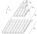
- FIG. 3 conceptually shows hierarchical data of moving images to be processed in the present embodiment.
- the hierarchical data has a hierarchical structure including a 0th hierarchy 30, a first hierarchy 32, a second hierarchy 34, and a third hierarchy 36 in the z-axis direction from the top to the bottom of the figure.
- each layer includes moving image data representing one moving image at different resolutions, that is, data in which a plurality of image frames are arranged in time series.
- each layer is symbolically represented by four image frames, but the number of image frames naturally varies depending on the playback time and frame rate of the moving image.
- the present embodiment is excellent in random accessibility to a three-dimensional space on the image plane and time axis of moving image data. Therefore, for example, by regarding the time axis as “depth”, three-dimensional volume data may be processed instead of moving image data.
- the type of parameter is not particularly limited as long as the data can have redundancy in the three-dimensional direction.
- the hierarchical data has a hierarchical structure of a quadtree, and when the image frames constituting each hierarchy are divided into “tile images” having the same size, the 0th hierarchy 30 is one tile image, and the first hierarchy 32 Is 2 ⁇ 2 tile images, the second layer 34 is 4 ⁇ 4 tile images, the third layer is 8 ⁇ 8 tile images, and the like.
- the resolution of the Nth layer (N is an integer of 0 or more) is 1 ⁇ 2 of the resolution of the (N + 1) th layer in both the left and right (x-axis) directions and the vertical (y-axis) direction on the image plane.
- Hierarchical data can be generated by reducing an image frame in a plurality of stages based on a moving image of the third hierarchy 36 having the highest resolution.
- the viewpoint coordinates at the time of moving image display and the corresponding display area are a virtual three-dimensional space composed of an x-axis representing the horizontal direction of the image, a y-axis representing the vertical direction, and a z-axis representing the resolution.
- x-axis representing the horizontal direction of the image
- y-axis representing the vertical direction
- z-axis representing the resolution.
- the image processing apparatus 10 basically draws image frames in any hierarchy sequentially at a predetermined frame rate along the time axis t. For example, a moving image having a resolution of the 0th hierarchy 30 is displayed as a reference image. If a display area movement request signal is supplied from the input device 20 in the process, the change amount of the display image is derived from the signal, and the coordinates of the four corners of the next frame in the virtual space (frame coordinates) are used by using the change amount. ) Is derived. Then, an image frame corresponding to the frame coordinates is drawn. At this time, by providing a layer switching boundary with respect to the z-axis, the layer of moving image data used for frame drawing is appropriately switched according to the value of z of the frame coordinates.
- the image processing apparatus 10 may derive information for specifying a hierarchy and texture coordinates (UV coordinates) in the hierarchy.
- texture coordinates UV coordinates
- the combination of the hierarchy specifying information and the texture coordinates is also referred to as frame coordinates.
- the hierarchical data is held in the storage device in a compressed state in a predetermined compression format. Data necessary for frame drawing is read from the storage device and decoded.
- FIG. 3 conceptually represents hierarchical data, and does not limit the storage order or format of data stored in the storage device. For example, if the position of the hierarchical data in the virtual space is associated with the storage area for the actual moving image data, the moving image data can be stored in an arbitrary area. As will be described later, space division or time division may be applied to the image frame sequence constituting each layer, and compression coding may be performed in that unit.
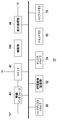
- FIG. 4 shows the configuration of the image processing apparatus 10.
- the image processing apparatus 10 includes a wireless interface 40, a switch 42, a display processing unit 44, a hard disk drive 50, a recording medium mounting unit 52, a disk drive 54, a main memory 60, a buffer memory 70, and a control unit 100.
- the display processing unit 44 has a frame memory that buffers data to be displayed on the display of the display device 12.
- the switch 42 is an Ethernet switch (Ethernet is a registered trademark), and is a device that transmits and receives data by connecting to an external device in a wired or wireless manner.
- the switch 42 is connected to an external network via the cable 14 and configured to receive hierarchical data from the image server.
- the switch 42 is connected to the wireless interface 40, and the wireless interface 40 is connected to the input device 20 using a predetermined wireless communication protocol.
- a display area movement request signal input from the user by the input device 20 is supplied to the control unit 100 via the wireless interface 40 and the switch 42.
- the hard disk drive 50 functions as a storage device that stores data.
- the hierarchical data may be stored in the hard disk drive 50.
- the recording medium mounting unit 52 reads data from the removable recording medium.
- the disk drive 54 drives and recognizes the ROM disk to read data.
- the ROM disk may be an optical disk or a magneto-optical disk.
- Hierarchical data may be stored in these recording media.
- the control unit 100 includes a multi-core CPU, and has one general-purpose processor core and a plurality of simple processor cores in one CPU.
- the general-purpose processor core is called PPU (Power Processing Unit), and the remaining processor cores are called SPU (Synergistic-Processing Unit).
- the control unit 100 may further include a GPU (Graphics Processing Unit).
- the control unit 100 includes a memory controller connected to the main memory 60 and the buffer memory 70.
- the PPU has a register, has a main processor as an operation execution subject, and efficiently assigns a task as a basic processing unit in an application to be executed to each SPU. Note that the PPU itself may execute the task.
- the SPU has a register, and includes a sub-processor as an operation execution subject and a local memory as a local storage area. The local memory may be used as the buffer memory 70.
- the main memory 60 and the buffer memory 70 are storage devices and are configured as a RAM (Random Access Memory).
- the SPU has a dedicated DMA (Direct Memory Access) controller as a control unit, can transfer data between the main memory 60 and the buffer memory 70 at high speed, and the frame memory and the buffer memory 70 in the display processing unit 44 High-speed data transfer can be realized.
- the control unit 100 according to the present embodiment realizes a high-speed image processing function by operating a plurality of SPUs in parallel.
- the display processing unit 44 is connected to the display device 12 and outputs an image processing result according to a request from the user.
- the image processing apparatus 10 sequentially transfers moving image data spatially and temporally close to the currently displayed frame from the hard disk drive 50 to the main memory in order to smoothly perform enlargement / reduction processing and scroll processing of the display image. 60 is loaded. Further, a part of the moving image data loaded in the main memory 60 is decoded and stored in the buffer memory 70. As a result, the display area can be smoothly moved while moving picture reproduction is progressing. At this time, the data to be loaded or decoded may be determined by pre-reading the necessary area based on the movement direction of the display area so far.
- the position in the z-axis direction indicates the resolution.
- the position closer to the 0th hierarchy 30 has a lower resolution, and the position closer to the third hierarchy 36 has a higher resolution.
- the position in the z-axis direction corresponds to the scale ratio.
- the scale ratio of the display image of the third hierarchy 36 is 1
- the scale ratio in the second hierarchy 34 is 1.
- the scale factor in the first hierarchy 32 is 1/16
- the scale factor in the 0th hierarchy 30 is 1/64.
- the display image when the display image changes in the direction from the 0th layer 30 side to the third layer 36 side, the display image expands and the direction from the third layer 36 side to the 0th layer 30 side. In the case of changing to, the display image is reduced. For example, when the scale ratio of the display image is in the vicinity of the second hierarchy 34, the display image is created using the image data of the second hierarchy 34.
- a switching boundary is provided for each intermediate scale ratio of each layer.
- the second hierarchy 34 when the scale ratio of the image to be displayed is between the switching boundary between the first hierarchy 32 and the second hierarchy 34 and the switching boundary between the second hierarchy 34 and the third hierarchy 36, the second hierarchy 34.
- a frame is drawn using the image data.
- the image frame of the second hierarchy 34 is scaled and displayed.
- the image frame of the second layer 34 is enlarged and displayed.
- the scale ratio of each layer is set as a prefetch boundary. For example, at least a part of the image data of the first hierarchy 32 in the reduction direction is transferred from the hard disk drive 50 or the main memory 60 when the requested scale ratio by the display area movement request signal crosses the scale ratio of the second hierarchy 34. Read ahead, decode and write to buffer memory 70.
- a prefetch boundary is set for the image data developed in the buffer memory 70, and the prefetch process is started when the display position by the image change request signal crosses the prefetch boundary.
- FIG. 5 shows in detail the configuration of the control unit 100a having a function of displaying moving images using moving image data having a hierarchical structure in the present embodiment.
- the control unit 100a includes an input information acquisition unit 102 that acquires information input by the user from the input device 20, a frame coordinate determination unit 110 that determines frame coordinates of a region to be newly displayed, and compression of a video stream to be newly loaded.
- a load stream determination unit 106 that determines data and a load unit 108 that loads a necessary moving image stream from the hard disk drive 50 are included.
- the control unit 100a further includes a decoding unit 112 that decodes the compressed data of the moving image stream, and a display image processing unit 114 that draws an image frame.
- each element described as a functional block for performing various processes can be constituted by a CPU (Central Processing Unit), a memory, and other LSIs in terms of hardware. Specifically, it is realized by a program loaded in a memory.
- the control unit 100 includes one PPU and a plurality of SPUs, and each functional block can be configured by the PPU and the SPU individually or in cooperation. Therefore, it is understood by those skilled in the art that these functional blocks can be realized in various forms by hardware only, software only, or a combination thereof, and is not limited to any one.
- the input information acquisition unit 102 acquires request contents such as start / end of moving image reproduction, movement of the display area, and the like input by the user to the input device 20 and notifies the frame coordinate determination unit 110 of them.
- the frame coordinate determination unit 110 determines the frame coordinates of a region to be newly displayed in accordance with the frame coordinates of the current display region and the display region movement request signal input by the user, the load stream determination unit 106, the decoding unit 112, the display
- the image processing unit 114 is notified.
- the load stream determination unit 106 Based on the frame coordinates notified from the frame coordinate determination unit 110, the load stream determination unit 106 identifies compressed video data to be newly loaded from the hard disk drive 50 to the main memory 60, and issues a load request to the load unit 108. Issue.
- the hierarchical data of the present embodiment individually holds a moving image stream for each tile image sequence obtained by spatially dividing the frame image sequence constituting each layer into the same size.
- the load stream determination unit 106 acquires necessary moving image stream identification information. If the compressed data of the corresponding video stream has not been loaded, a load request is issued to the load unit 108. Further, even if the frame coordinates do not change, it is requested that the compressed data of the necessary moving image stream is sequentially loaded according to the progress of the moving image.
- the load stream determination unit 106 identifies a video stream that is predicted to be necessary in addition to the video stream necessary for frame drawing at that time by the pre-read process described above, and issues a load request to the load unit 108. Good.
- the load stream determination unit 106 may make a load request at a predetermined timing in a state where the load unit 108 is not performing the load process, for example, at a predetermined time interval or when the user inputs a display area movement request.
- the load unit 108 performs load processing from the hard disk drive 50 in accordance with a request from the load stream determination unit 106. Specifically, the storage area is specified from the identification information of the moving picture stream to be loaded, and the data read from the storage area is stored in the main memory 60.
- the decoding unit 112 reads and decodes the necessary moving picture stream data from the main memory 60 based on the frame coordinates at each time, and sequentially stores them in the buffer memory 70.
- the decoding target may be a moving image stream unit, and when the frame coordinate area determined by the frame coordinate determining unit 110 extends over a plurality of moving image streams, the plurality of moving image streams are decoded.
- the display image processing unit 114 reads the data of the corresponding image frame from the buffer memory 70 based on the frame coordinates at each time, and draws it in the frame memory of the display processing unit 44.
- the unit for generating the moving image stream and the overall configuration are It can be appropriately changed according to the compression method and the content of the moving image.
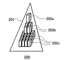
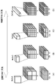
- 6 to 9 show examples of the structure of moving image data to be processed in the present embodiment.
- the triangle represents the hierarchical data of the moving image
- the rectangular parallelepiped represents one moving image stream.
- Each hierarchical data consists of three hierarchies of the zeroth hierarchy, the first hierarchy, and the second hierarchy, but the number of hierarchies is not limited to that.
- one moving image stream is generated for each tile image obtained by dividing the image frame of each layer into the same size.
- the size of the 0th layer image is set as the size of the tile image.
- the moving image data structure 200 shown in FIG. 6 includes one layer data 201 in which each layer is one moving image stream for each tile image from the start to the end of the moving image.
- the 0th layer is one moving image stream 202a
- the first layer is 4 moving image streams 202b
- the second layer is 16 The video stream 202c and the like.
- the length of the moving image stream in the time direction varies depending on the length of the original moving image, that is, the number of original image frames. Therefore, it is advantageous when the number of image frames is originally small, or when a compression method capable of long-term data compression and random access, for example, MPEG (Moving Picture Experts Group) using all frames as I pictures is used. It is.
- MPEG Motion Picture Experts Group
- the moving picture data structure 204 shown in FIG. 7 is composed of one hierarchical data 205 in which the moving picture data is divided by a predetermined number of image frames, and each hierarchy is a plurality of moving picture streams in the time axis direction for each tile image. That is, the moving image stream in FIG. 6 is obtained by dividing each moving image stream shown in FIG. 6 with respect to the time axis which is the vertical direction of the drawing. In this example, the moving picture stream of FIG. 6 is divided into six moving picture streams. Therefore, the 0th layer is composed of 1 ⁇ 6 moving image streams 206a, the first layer is composed of 4 ⁇ 6 moving image streams 206b, the second layer is composed of 16 ⁇ 6 moving image streams 206c, and the like. This structure is used when a compression method that performs compression in units of a fixed number of image frames is used.
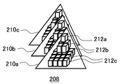
- the moving image data structure 208 shown in FIG. 8 has a configuration in which moving image data is divided by a predetermined number of image frames, and different hierarchical data 210a, 210b, and 210c are generated for each moving image stream generated in that unit. That is, each hierarchical data 210a, 210b, 210c is composed of one moving image stream in the time axis direction for each layer as in FIG. 6, but each moving image stream has a fixed number of image frames. For example, in the hierarchical data 210a, the 0th layer is composed of one moving image stream 212a, the first layer is composed of 4 moving image streams 212b, and the second layer is composed of 16 moving image streams 212c.
- the moving picture data structure 208 in FIG. 8 since it is composed of a plurality of hierarchical data in the time axis direction, only a certain scene is replaced with another hierarchical data, or hierarchical data is inserted or deleted. Easy video editing in any direction.
- the data size is easy to estimate.
- the data of each moving picture stream can have the same structure as the data of the tile image when the still picture has the same hierarchical structure. Coexistence with a still image such as an image display or a partial image as a still image is facilitated.
- the moving picture data structure 214 shown in FIG. 9 has a configuration in which the moving picture data is divided by a predetermined number of image frames, and the moving picture stream generated in that unit is further divided into a predetermined number of pieces to form different hierarchical data 216a, 216b, and 216c. That is, each hierarchical data 216a, 216b, 216c is composed of a plurality of moving image streams in the time axis direction for each layer as in FIG. 7, but the number is fixed regardless of the length of the moving image. In this case, the hierarchy data is divided by using two.
- the 0th layer includes 1 ⁇ 2 moving image streams 218a
- the first layer includes 4 ⁇ 2 moving image streams 218b
- the second layer includes 16 ⁇ 2 moving image streams 218c. Also in this case, it is easy to estimate and adjust the data size of each layer constituting one layer data, and it is easy to edit a moving image in the time axis direction by replacing the layer data.
- FIGS. 6 to 9 all retain the moving image stream so as to cover the entire area of the image frame in each layer. However, some moving image streams depend on the redundancy of the moving image. May be omitted from the moving image data and replaced with a moving image stream of a different level.
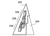
- FIG. 10 schematically shows the data structure of a moving image when a moving image stream of a part of the hierarchy is replaced with a moving image stream of another layer. The way of representing the data structure is the same as in FIG. In the hierarchical data 222 shown in the figure, the moving picture stream corresponding to the area 224 is omitted.
- the number of moving picture streams is smaller in the first hierarchy 228 and the second hierarchy 230. This is a video stream from which this difference is omitted.
- the area represented by the omitted moving image stream has no data in the hierarchy. Therefore, when displaying the corresponding area at a scale ratio that should use data of such a hierarchy, the hierarchy is held up to the hierarchy holding the data of the applicable area, in the example of FIG. And draw.
- Such an aspect can be applied to a case where there is an area that does not require detailed information in the image frame, for example, an area composed of almost a single color such as sky, sea, or lawn.
- the presence or absence of redundancy in the image frame can be detected by image analysis. For example, for each image frame at each time, a difference image between an image obtained by enlarging an image frame on the low resolution side and an image on the high resolution side is generated, and an area where the difference value is equal to or less than a predetermined threshold is detected. . Then, among the video streams included in the area, the high-resolution layer video stream is excluded from the video data.
- the size of the moving image data can be kept small, and a part of the loading processing of the moving image stream can be omitted.
- identification of the moving image stream of the upper layer used in an enlarged manner with respect to the coordinates of the area corresponding to the excluded moving image stream Drawing is possible by associating information and adding information such as an enlargement ratio.
- FIG. 10 is a mode that is realized by the present embodiment having both the feature that the moving image data has a hierarchical structure and the feature that the frame image is spatially divided and the moving image stream is individually generated.
- the data retention format can be locally changed, and data with a lower resolution can be used instead, so some data is omitted.
- Data size can be reduced.
- only a part of moving image streams may be thinned out to reduce the number of image frames, thereby reducing the data size.
- the time resolution of the area handled by the moving picture stream is reduced, it is effective for moving pictures including areas with little temporal change such as the background.
- the temporal redundancy at this time can be specified by, for example, detecting a region having a difference value equal to or less than a predetermined threshold among the difference images between adjacent image frames.
- some moving picture streams can be replaced with still images.
- the compression method may be different for each video stream.
- various image representations can be realized by intentionally shifting the time axis in predetermined units such as for each hierarchy, for each moving picture stream, for each pixel column in the image. It may be.
- the hierarchical structure of the moving image data to be displayed in the present embodiment is not particularly limited with respect to the compression method of each moving image stream, such as JPEG (Joint Photographic Experts Group), MPEG, S3TC (S3 Texture Compression), etc. Any of the existing methods may be applied. However, in order to enable seamless movement of the display area, including layer switching, spatial and random access is possible, and both image quality and decoding throughput are maintained even for high-definition images. It is desirable to be able to do it.
- JPEG Joint Photographic Experts Group
- MPEG Joint Photographic Experts Group
- S3TC S3 Texture Compression
- a method for compressing a moving picture stream in units of a fixed number of image frames which can be applied to the moving picture data structure shown in FIGS.
- the compression method can be applied not only to a plurality of moving image streams constituting hierarchical data but also to a single moving image stream.
- An apparatus that implements this compression technique can also be realized with the same configuration as the image processing apparatus 10 shown in FIG. Hereinafter, the description will be given focusing on the configuration of the control unit 100.
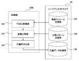
- FIG. 11 shows in detail the configuration of the control unit 100b having the moving image data compression function and the hard disk drive 50 in the present embodiment.
- the control unit 100b includes a YCbCr conversion unit 120 that converts a color space of an image frame constituting a moving image stream to be compressed into YCbCr, an image division unit 122 that generates a coding unit by space-time dividing the converted image sequence, and A compression encoding unit 124 that performs compression encoding processing by quantizing the image data for each of the divided encoding units is included.
- the hard disk drive 50 includes a moving image stream storage unit 126 that stores a moving image stream to be compressed including individual image frame sequences, a division pattern storage unit 128 that stores division patterns when the image dividing unit 122 divides the image sequence, and A compressed data storage unit 130 for storing compressed data generated by compression encoding by the compression encoding unit 124 is included.
- the YCbCr conversion unit 120 sequentially reads out the data of the image frames constituting the moving image stream to be compressed from the moving image stream storage unit 126. Then, by converting the RGB value, which is the pixel value of each image frame, into luminance Y and color differences Cb and Cr, a Y image, a Cb image, and a Cr image having the respective values as pixel values are generated.
- An existing method can be applied to the conversion of the color space from RGB to YCbCr. Since a Y image, a Cb image, and a Cr image are generated from one image frame, a Y image sequence, a Cb image sequence, and a Cr image sequence are generated for a plurality of image frames that form a moving image stream.
- the image dividing unit 122 first reduces each Cb image and Cr image at a predetermined ratio among the Y image sequence, Cb image sequence, and Cr image sequence generated by the YCbCr conversion unit 120. Then, the Y image sequence, the Cb image sequence, and the Cr image sequence are spatiotemporally divided by the division patterns stored in the division pattern storage unit 128. A unit generated by the division is referred to as “coding unit”.
- the image division unit 122 may perform a process of selecting an optimum pattern from a plurality of division patterns stored in the division pattern storage unit 128. .
- the Cb image and the Cr image reduced in the subsequent processing are handled as a set for each corresponding frame.
- such a set of Cb image and Cr image is simply referred to as “CbCr image”.
- the compression encoding unit 124 includes a palette representing two representative values for each encoding unit of the Y image and the CbCr image, and a plurality of intermediate values obtained by linearly interpolating the two representative values and the representative value. By generating an index that designates either one for each pixel, the image data is quantized and compression-coded. Thereby, a palette and an index are generated for each encoding unit of the Y image sequence and each encoding unit of the CbCr image sequence.
- FIG. 12 schematically illustrates a moving image stream compression procedure performed by the image processing apparatus 10 including the control unit 100b.
- the moving image stream 250 to be compressed may correspond to, for example, a moving image stream indicated by a rectangular parallelepiped in FIGS.
- the moving image stream 250 is composed of image frames of RGB images.
- the moving picture stream 250 is compressed every predetermined number of image frames, that is, every 8 frames in the example of FIG.
- the YCbCr conversion unit 120 further divides the image frame for eight frames into a predetermined size and determines a processing unit in a three-dimensional space of the image plane (x, y) and the time axis t.
- data of 8 pixels ⁇ 8 pixels ⁇ 8 frames is used as a processing unit 252.
- eight Y image sequences 254 and CbCr image sequences 256 are generated from the eight RGB images included in the processing unit 252 (S10).
- the CbCr image sequence 256 is an image sequence obtained by reducing the Cb image and Cr image directly obtained from the original RGB image to 1/2 size in both the vertical and horizontal directions. Therefore, the Y image row 254 has 8 image frames of 8 pixels ⁇ 8 pixels, and the CbCr image row 256 has 8 frames of images obtained by connecting a Cb image of 4 pixels ⁇ 4 pixels and a Cr image of 4 pixels ⁇ 4 pixels. .
- the image dividing unit 122 performs space-time division on the Y image sequence 254 and the CbCr image sequence 256 with any one of the division patterns stored in the division pattern storage unit 128 to form a coding unit (S12). ).
- a coding unit S12
- an image block obtained by spatially dividing each image frame of the Y image sequence 254 and the CbCr image sequence 256 with the same size of 4 horizontal pixels ⁇ 2 vertical pixels is divided into two images adjacent in the time direction. Data of 4 pixels ⁇ 2 pixels ⁇ 2 pieces divided for each frame is used as an encoding unit.
- each image frame has “A”, “B”, “C”, “D”, “E”, “F”, “G”, “ The image block “A” is divided into eight image blocks “H”, and the image block “A” of the first frame and the image block “A” of the second frame form an encoding unit 258 (shaded area). The same applies to the other image blocks and image frames.
- the CbCr image sequence 256 is 4 pixels ⁇ 4 pixels for both the Cb image and the Cr image, the former is divided into two image blocks of “I” and “J”, and the latter of “K” and “L”.
- the image blocks “I” and “K” of the first frame and the image blocks “I” and “K” of the second frame form an encoding unit 260 (shaded area).
- the compression encoding unit 124 generates palette and index data for each encoding unit.
- the palette and the index are basically the same as the palette and the index generated from the RGB image in the S3TC texture compression method.
- the number of parameter dimensions is different from that of general S3TC.
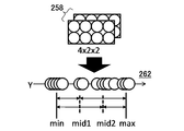
- FIG. 13 schematically shows a method for generating palette and index data from the encoding unit 258 of the Y image sequence 254.
- the luminance Y value that internally divides the line segment between the minimum value and the maximum value by 1: 2 is the first intermediate value (mid1), and the luminance Y value that is internally divided by 2: 1.
- the second intermediate value (mid2) data that stores information specifying any one of the four values of the minimum value, the first intermediate value, the second intermediate value, and the maximum value is used as an index.
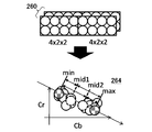
- FIG. 14 schematically shows a method of generating palette and index data from the encoding unit 260 of the CbCr image sequence 256.
- 2 representative values are selected.
- the color difference at the left end and the right end of the straight line is set as a representative value as a minimum value (min) and a maximum value (max), respectively.
- the data holding the binary values is set as a palette.
- each representative value is a two-dimensional parameter having (color difference Cb, color difference Cr) as an element.
- the color difference that internally divides the line segment between the minimum value and the maximum value by 1: 2 is the first intermediate value (mid1)
- the color difference that internally divides by 2: 1 is the second intermediate value (mid2).
- data that stores information specifying any one of the four values of the minimum value, the first intermediate value, the second intermediate value, and the maximum value is used as an index.
- an RGB image of 8 pixels ⁇ 8 pixels ⁇ 8 frames in one processing unit is 256 in total, including a palette of 64 bytes and an index of 128 bytes for a Y image sequence, and a palette of 32 bytes and an index of 32 bytes for a CbCr image sequence. It becomes a byte. That is, the data is 0.5 bytes per pixel.
- the index is information representing the identification numbers of 4 values of RGB values as 0 to 3
- the RGB image is decomposed into a Y image that holds a one-dimensional parameter and a CbCr image that holds a two-dimensional parameter, and then a palette and an index are generated. Therefore, in the case of a one-dimensional Y image, all sample values are distributed on a straight line, and in a two-dimensional CbCr image, the sample deviating from the approximate line is only in the normal direction of the approximate line. Therefore, compared with a general S3TC method in which an RGB image holding three-dimensional parameters is approximated by a straight line and quantized, the quantization error can be suppressed small.
- FIG. 15 shows a variation of a pattern for dividing one processing unit. Pattern (A), pattern (B), pattern (C), and pattern (D) are shown from the left end of the figure, and each of the upper Y image sequence and the lower CbCr image sequence indicates a space division delimiter with a straight line.
- One coding unit is represented by shading.
- Pattern (A) is a pattern divided into 4 horizontal pixels ⁇ 4 vertical pixels ⁇ 1 frame.
- the pattern (B) is the same as the pattern shown in FIG.
- Pattern (C) is a pattern divided into 2 horizontal pixels ⁇ vertical 2 pixels ⁇ 4 frames
- pattern (D) is a pattern divided into 2 horizontal pixels ⁇ 1 vertical pixel ⁇ 8 frames.
- each of these patterns since one processing unit is 16 pixels for the Y image sequence and 16 pixels ⁇ 2 for the CbCr image sequence, the number of samples at the time of quantization is as shown in FIG. 13 and FIG. The same.
- the more detailed time division is performed from the pattern (D) to the pattern (A)
- the more detailed space division is performed from the pattern (A) to the pattern (D).
- Such a division pattern is prepared, and the division pattern is selected according to the characteristics of the image, such as whether it has redundancy in the spatial direction or redundancy in the temporal direction.
- the image has spatial redundancy, such as the sky and turf contain many areas close to a single color, the pixel values tend to be more uniform with respect to the space, and the number of space divisions can be reduced. Since an error due to quantization is difficult to be included, a divided pattern close to the pattern (A) is selected.
- the image has temporal redundancy, such as when a fixed-point view of a scene with little motion is observed, the pixel values are likely to be uniform in the time direction, and even if the number of time divisions is reduced, errors due to quantization are not easily included. Therefore, a division pattern close to the pattern (D) is selected.
- one coding unit has only two pixels in the spatial direction. If there is no time change for 8 frames included in the same encoding unit, the two representative values held in the palette represent the original pixel values as they are, and the quantization error is zero.
- the RGB image is compressed by the S3TC method, the RGB data held in the palette is reduced from the original 24 bits to 16 bits, so that sufficient gradation cannot be obtained when decoding, such as image quality. A decrease may occur.
- an 8-bit palette is prepared for each of the luminance Y and the color differences Cb and Cr, so that there is a high possibility that the original image quality can be maintained.
- the division pattern storage unit 128 stores four types of division patterns (A) to (D) and information for identifying them, for example, four identification numbers 0, 1, 2, and 3 in association with each other. Keep it.
- the image division unit 122 performs all the division patterns stored in the division pattern storage unit 128 for each image sequence generated by the YCbCr conversion unit 120, and selects a division pattern with the least error from the original image.
- this processing causes the compression encoding unit 124 to perform compression encoding of the image sequence when divided by each division pattern, and compares the image obtained by decoding each compressed data with the image before compression for each image frame. To do. Then, a division pattern with a small difference may be selected.
- the image dividing unit 122 notifies the identification number of the selected division pattern to the compression encoding unit 124, and the compression encoding unit 124 includes the information of the identification number in the generated compressed data as final compressed data. And stored in the compressed data storage unit 130.
- the division pattern may be different for each region in the image.
- the procedure for selecting the division pattern for each region may be the same as described above.
- the image division unit 122 generates a map in which the identification number of the selected division pattern is associated with the region, and includes the map in the final compressed data.
- FIG. 16 shows an example of the data structure of the division pattern map. The example in the figure shows a case where one moving picture stream is composed of image frames of 256 pixels ⁇ 256 pixels.
- the minimum unit that can set the division pattern is 8 pixels ⁇ 8 pixels ⁇ 8 frames, which is one processing unit.
- the example of FIG. 16 is a case where the division pattern is set for each minimum unit of 8 pixels ⁇ 8 pixels. Similarly, for example, every 16 pixels ⁇ 16 pixels, every 64 pixels ⁇ 32 pixels, etc. A division pattern may be set for each region obtained by connecting regions of 8 pixels ⁇ 8 pixels in the direction. Also, the setting unit itself can be set variously, such as setting one division pattern for all the areas.
- the division pattern map can be generated by decoding the data that was actually compressed and encoded as described above and with a small error from the original image. In addition, the division pattern map can be set by the test image having the same contents and the division pattern set there You may have prepared.
- the compressed data generated in the present embodiment is composed of palettes and indexes as in the S3TC texture compression method. Therefore, the decoding process can use a general GPU shading function included in the control unit 100 of the image processing apparatus 10 of FIG. 4 as it is.
- the index and palette generated by quantizing the data of the Y image sequence and the index and palette generated by quantizing the data of the CbCr image sequence can be read and decoded in the same manner as a normal texture image. It is desirable to do. Therefore, when storing compressed data, the quantized data of the Y image sequence and the quantized data of the CbCr image sequence representing the same region are combined into one, so that the pixels can be restored with a small number of data accesses.
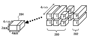
- FIG. 17 is a diagram for explaining the arrangement of compressed data in the compressed data storage unit 130.
- the compressed data 280 for the Y image sequence and the compressed data 282 for the CbCr image sequence representing the same area are collected as one storage unit.
- the rectangular parallelepiped denoted as “I” is generated from one encoding unit
- the rectangular parallelepiped denoted as “P” is generated from one encoding unit. It is a pallet.
- the compressed data 282 for the CbCr image sequence As described above, the index and palette of the Y image sequence are 4 bytes and 2 bytes of data per encoding unit, respectively. Both the index and palette of the CbCr image sequence are 4 bytes of data per encoding unit.
- each palette is 2-byte data, so by arranging two in the depth direction as shown in the figure, 2 ⁇ 4 ⁇ 4 bytes of data in the vertical direction. It becomes.
- the Y image sequence and the CbCr image sequence representing the same area are, for example, the image blocks “A”, “B”, “C”, “D” of the Y image and the image block “I” of the Cb image in FIG. , The image block “K” of the Cr image.
- the compressed data When the compressed data is collected in this way, it can be stored as it is in the storage area 284 for storing RGBA image data of 2 pixels in the vertical direction ⁇ 4 pixels in the horizontal direction.
- 32 encoding units are formed for the Y image sequence and 8 encoding units are formed for the CbCr image sequence per processing unit of 8 pixels ⁇ 8 pixels ⁇ 8 frames, so that there are 8 storage units per processing unit.
- Individually formed Since one storage unit has the same data size as an RGBA image of 2 pixels in the vertical direction and 4 pixels in the horizontal direction, the data is equivalent to an RGBA image of 8 pixels ⁇ 8 pixels per processing unit. This feature is the same for any division pattern shown in FIG.
- FIG. 18 schematically shows the transition of data when the compression encoding process described so far is applied to the entire moving picture stream.
- the moving image stream is composed of image frames of RGB images of 256 pixels ⁇ 256 pixels and is compressed in units of 8 frames.
- 8 image frames are divided into processing units of 8 pixels ⁇ 8 pixels (S20). As a result, 32 processing units are formed in the vertical and horizontal directions.
- YCbCr conversion is performed on each processing unit to generate a Y image and a reduced CbCr image, and each is divided into coding units, and an index and a palette are generated.
- eight storage units are generated per processing unit (S22). As a result, the RGB images for 8 frames are compressed into 1 frame of RGBA image having the same number of pixels.
- each palette stores binary values that are representative values of luminance Y. Therefore, 2-bit information for identifying the four division patterns is embedded using two palettes arranged side by side in the depth direction among the four palettes included in one storage unit.
- FIG. 19 is a diagram for explaining a method of embedding the identification number of the division pattern in the two pallets.
- the two values held by the first pallet 290 are “Pa0” and “Pa1” in order from the head address in the front of the figure, and the two values held by the second pallet 292 are “Pb0” in the address order.
- information of 2 bits in total is represented by the magnitude relationship between “Pa0” and “Pa1” and the magnitude relationship between “Pb0” and “Pb1”.
- 1-bit information is represented by “1” if “Pa0” of the first pallet 290 is larger than “Pa1” and “0” otherwise.
- Pb0 of the second pallet 292 is larger than “Pb1”
- “1” is set, and “0” is expressed otherwise.
- the binary value held by the palette does not affect the decoding process, whichever is stored at the previous address. Therefore, the identification number of the divided pattern can be embedded in the pallet by changing the address in which the larger value is stored in each pallet according to the identification number of the divided pattern.
- the division pattern map can be included in the compressed data without being generated separately from the main body of the compressed data, and the data size can be suppressed as a whole.
- the efficiency in referring is good.
- the same division pattern may be embedded in all 16 pairs of pallets included in the eight storage units.
- the Y image sequence palette in which the division pattern is embedded is read, and the identification number of the division pattern set in the processing unit To identify.
- the pixel can be associated with the storage location of the index and pallet containing the data necessary for drawing the pixel. Accordingly, the index and palette of the Y image sequence and the index and palette of the CbCr image sequence corresponding to the drawing target pixel may be read and decoded.
- Decoding processing can be basically performed in the same manner as S3TC. That is, an intermediate value that interpolates the representative value held by each palette is generated, and the representative value or the intermediate value is set as the pixel value of each pixel according to the designation in the index.
- the determined pixel value is based on the arrangement of the encoding units in the image sequence corresponding to the division pattern, and in the spatial direction and the temporal direction.
- the Y image sequence and the CbCr image sequence are restored by reconstructing the pixel arrangement. Then, by enlarging the CbCr image to generate a Cb image and a Cr image, a YCbCr image corresponding to the original image frame is obtained.
- hierarchical data is generated by hierarchizing a plurality of video streams representing image frames constituting a video at different resolutions, and the display area is moved in response to a viewpoint movement request from the user. To display the video.
- the hierarchy of data used for frame drawing according to the required scale ratio, even a general high-definition image or a moving image with a resolution higher than that can be enlarged to confirm details or have a bird's-eye view. Requests can be sequentially received and displayed with good responsiveness.
- the video stream that configures each layer of the layer data is configured with image frames of the same size in any layer.
- the higher the resolution the greater the number of video streams that make up one hierarchy.
- the entire moving image may not be composed of one hierarchical data, but may be divided on the time axis to be composed of a plurality of hierarchical data.
- the moving picture stream of each layer included in one hierarchical data may be one moving picture compressed data over the entire volume, or may be different moving picture compressed data for each predetermined number of image frames.
- the processing load when displaying moving images can be selected by appropriately selecting the number of hierarchical data, the data structure of the video stream in the hierarchical data, and the compression encoding format depending on the content of the moving image and the playback time. Therefore, an optimum display mode can be realized from various viewpoints such as required image quality.
- the moving image stream is compression-coded for every predetermined number of image frames.
- an image in which the RGB image of the image frame constituting the original moving image stream is represented by luminance Y, color difference Cb, and Cr is generated.
- each image sequence is divided into a predetermined size and a predetermined number of image frames to generate a coding unit.
- palette and index data are generated for each of the Y image sequence and the CbCr image sequence.
- the palette is binary data representing the representative value of each image
- the index is data for designating one of the intermediate value and representative value obtained by linear interpolation of the representative value for each pixel.
- the concept of palette and index is introduced in the S3TC compression method for texture RGB images, but in this embodiment, the binary value of the palette is 8 bits for all of luminance Y, color difference Cb, and color difference Cr. Image quality is unlikely to deteriorate due to retention.
- the quantization is separately performed on the Y image sequence and the CbCr image sequence, the number of parameter dimensions is smaller and the quantization error is smaller than when the RGB three-dimensional parameters are quantized.
- the rendering process can be performed in the same manner as the texture mapping process by the GPU. Therefore, the video stream in the display area is read while the hierarchy is switched, and the image is rendered at a predetermined frame rate. High throughput that can be applied to hierarchically structured video data can be expected.
- the processing load of decoding tends to increase depending on the content of the image.
- MPEG requires decoding of I pictures for each of a plurality of moving picture streams. As a result, the processing load tends to increase, and if I pictures are reduced, there is a problem that latency tends to occur for random access in the time direction. .
- the compression encoding technique in the present embodiment realizes high-speed drawing as compared with the above existing technique by realizing decoding with GPU. As a result, a high-definition moving image can be displayed while reducing the processing load on the CPU. For this reason, it is possible to perform additional processing in the CPU, and the risk of dropping frames is reduced even in a device such as a portable terminal having inferior CPU processing performance. This feature can be said to be suitable for future technological trends in which data reading from a storage device is accelerated with the spread of SSD (Solid Sate Drive) and decoding processing is likely to become a bottleneck.
- SSD Solid Sate Drive
- this compression coding technology can achieve high-throughput rendering while maintaining image quality, and also enables temporal and spatial random access with low latency, so high-definition video can be displayed while changing the display area.
- 1 image processing system 10 image processing device, 12 display device, 20 input device, 30 0th layer, 32 1st layer, 34 2nd layer, 36 3rd layer, 44 display processing unit, 50 hard disk drive, 60 main memory , 70 buffer memory, 100 control unit, 102 input information acquisition unit, 106 load stream determination unit, 108 load unit, 110 frame coordinate determination unit, 112 decoding unit, 114 display image processing unit, 120 YCbCr conversion unit, 122 image division unit , 124 compression encoding unit, 126 video stream storage unit, 128 division pattern storage unit, 130 compressed data storage unit.
- the present invention is applicable to information processing apparatuses such as computers, image processing apparatuses, image display apparatuses, and data compression apparatuses.
Abstract
動画像のデータは、図の上から下へ向かうz軸方向に、第0階層30、第1階層32、第2階層34および第3階層36からなる階層構造とする。各階層は1つの動画像を異なる解像度で表した動画データ、すなわち複数の画像フレームを時系列順に並べたデータで構成する。動画表示時の視点座標およびそれに対応する表示領域は、画像の左右方向を表すx軸、上下方向を表すy軸、解像度を表すz軸からなる仮想的な3次元空間で定まる。z軸に対し階層の切り替え境界を設けておくことにより、フレーム座標のzの値に応じて、フレーム描画に用いる動画データの階層を切り替える。
Description
本発明は、動画像を表示する画像処理装置および画像処理方法、動画像などの3次元データを符号化、復号化する情報処理装置および情報処理方法に関する。
ゲームプログラムを実行するだけでなく、動画を再生できる家庭用エンタテインメントシステムが提案されている。この家庭用エンタテインメントシステムでは、GPUがポリゴンを用いた三次元画像を生成する(例えば特許文献1参照)。
動画、静止画に関わらず、画像をいかに効率よく表示するかは常に重要な問題となる。そのため画像データの圧縮技術、伝送技術、画像処理技術、表示技術など多方面で様々な技術が開発、実用化され、高精細な画像を多様な場面で身近に楽しめるようになってきた。
高精細な画像をユーザの要求に従い応答性よく表示させたい、という要求は常に存在する。例えば表示させた全体画像のうちユーザが着目したい領域を拡大して表示させたり別の領域に移動したり、といった、ユーザの視点に対し自由度のある画像表示を応答性よく実現するためには、サイズの大きな画像データを短時間で処理しつつランダムアクセスをも可能にしなければならず、さらなる技術の進歩が求められている。
本発明はこのような課題に鑑みてなされたものであり、その目的はユーザによる表示領域に係る操作入力に対し応答性よく高精細な動画像を表示することのできる画像処理技術を提供することにある。また別の目的は、様々な要求に対し応答性よく動画像などの3次元データを出力することのできる情報処理技術を提供することにある。
本発明のある態様は画像処理装置に関する。この画像処理装置は、一の動画を構成する画像フレームを異なる解像度で表した複数の画像フレーム列を解像度順に階層化してなる階層動画データを格納した動画データ記憶部と、ユーザによる表示領域に係る操作入力の情報を逐次取得する入力情報取得部と、入力情報取得部が取得した操作入力の情報に従い、動画のうち表示する領域を変化させながら、階層動画データを用いて、表示装置に表示する動画像を生成する表示画像処理部と、を備え、表示画像処理部は、操作入力の情報によって定まる解像度の変化に応じて、階層動画データのうち動画像の生成に用いる階層を切り替えることを特徴とする。
本発明のさらに別の態様は画像処理方法に関する。この画像処理方法は、一の動画を構成する画像フレームを異なる解像度で表した複数の画像フレーム列を解像度順に階層化してなる階層動画データを記憶装置から読み出し、それを用いて表示装置に表示する動画像を生成するステップと、ユーザによる表示領域に係る操作入力の情報を取得するステップと、操作入力の情報に従い、動画のうち表示する領域を変化させるステップと、を含み、変化させるステップは、操作入力の情報によって定まる解像度の変化に応じて、階層動画データのうち動画像の生成に用いる階層を切り替えるステップを含むことを特徴とする。
本発明のさらに別の態様は動画像ファイルのデータ構造に関する。このデータ構造は、表示装置に表示するための動画像ファイルのデータ構造であって、ユーザによる表示領域に係る操作入力によって定まる解像度と、一の動画を構成する画像フレームを異なる解像度で表した複数の画像フレーム列であり、解像度に応じて切り替えて用いられる画像フレーム列と、を対応づけたことを特徴とする。
本発明のさらに別の態様はデータ圧縮装置に関する。このデータ圧縮装置は、圧縮対象の、3次元空間におけるデータ列を当該3次元方向に分割して符号化単位を形成するデータ分割部と、データ分割部が形成した符号化単位ごとに、データのうち2値を代表値として保持するパレットと、当該代表値を線形補間して定まる複数の中間値および代表値のいずれかを指定する情報を、当該符号化単位の元のデータに代えて保持するインデックスと、を生成して圧縮データとする圧縮符号化部と、を備えたことを特徴とする。
本発明のさらに別の態様はデータ復号装置に関する。この動画データ復号装置は、3次元空間におけるデータ列を、当該3次元方向に分割して形成した符号化単位ごとに、画素値のうち2値を代表値として保持するパレットと、当該代表値を線形補間して定まる複数の中間値および代表値のいずれかを指定する情報を、当該符号化単位の元のデータに代えて保持するインデックスと、を対応づけた圧縮データを記憶装置から読み出す圧縮データ読み出し部と、パレットが保持する代表値を線形補間して中間値を生成し、インデックスが保持する情報に従い、各符号化単位に含まれるデータを代表値および中間値のいずれかに決定したうえ、符号化単位の配列に基づき、元のデータ列を再構成して生成する復号部と、を備えたことを特徴とする。
本発明のさらに別の態様はデータ圧縮方法に関する。このデータ圧縮方法は、圧縮対象の、3次元空間におけるデータ列を記憶装置より読み出すステップと、データ列を3次元方向に分割して符号化単位を形成するステップと、符号化単位ごとに、データのうち2値を代表値として保持するパレットと、当該代表値を線形補間して定まる複数の中間値および代表値のいずれかを指定する情報を、当該符号化単位の元のデータに代えて保持するインデックスと、を生成して圧縮データとして記憶装置に格納するステップと、を含むことを特徴とする。
本発明のさらに別の態様はデータ復号方法に関する。このデータ復号方法は、3次元空間におけるデータ列を、当該3次元方向に分割して形成した符号化単位ごとに、画素値のうち2値を代表値として保持するパレットと、当該代表値を線形補間して定まる複数の中間値および代表値のいずれかを指定する情報を、当該符号化単位の元のデータに代えて保持するインデックスと、を対応づけた圧縮データを記憶装置から読み出すステップと、パレットが保持する代表値を線形補間して中間値を生成し、インデックスが保持する情報に従い、各符号化単位に含まれるデータを代表値および中間値のいずれかに決定したうえ、符号化単位の配列に基づき、元のデータ列を再構成して生成するステップと、生成したデータ列を出力装置に出力するステップと、を含むことを特徴とする。
本発明のさらに別の態様は圧縮動画像ファイルのデータ構造に関する。このデータ構造は、動画を構成する画像フレーム列に対応し、輝度Yを画素値とするY画像列、色差Cbを画素値とするCb画像列、色差Crを画素値とするCr画像列を、それぞれ時空間分割して形成した符号化単位ごとに生成された、画素値のうち2値を代表値として保持するパレットと、当該代表値を線形補間して定まる複数の中間値および代表値のいずれかを指定する情報を画素ごとに保持するインデックスと、を対応づけて画像フレームの画像領域に対応させて配列したことを特徴とする。
なお、以上の構成要素の任意の組合せ、本発明の表現を方法、装置、システム、コンピュータプログラムなどの間で変換したものもまた、本発明の態様として有効である。
本発明によると、ユーザの操作入力に対し円滑に応答できる動画像表示を実現できる。さらにランダムアクセスが可能でスループットの高い3次元データ出力を行える。
本実施の形態では動画像表示において、ユーザの視点移動要求に対応した表示領域の移動を可能にする。ここでの視点移動は、画像平面へ視点を近づけたり離したりすることを含み、それに応じて動画像は、再生されつつ拡大および縮小されることになる。そこで本実施の形態では処理対象の動画像データを、1つの動画像を異なる解像度で表した画像フレーム列からそれぞれ構成される複数の動画像ストリームを解像度順に階層化してなる階層構造とする。そして視点の遠近方向の移動要求に対し、表示に使用する動画ストリームを異なる階層へ切り替えることで、拡大表示や縮小表示を迅速に行う。以後、このような階層構造を有する動画像データを「階層データ」とも呼ぶ。
まず、このような階層データの基本的な表示態様について説明する。図1は、本実施の形態を適用できる画像処理システム1の使用環境を示す。画像処理システム1は、画像処理ソフトウェアを実行する画像処理装置10と、画像処理装置10による処理結果を出力する表示装置12とを備える。表示装置12は、画像を出力するディスプレイおよび音声を出力するスピーカを有するテレビであってよい。
表示装置12は、画像処理装置10に有線ケーブルで接続されてよく、また無線LAN(Local Area Network)などにより無線接続されてもよい。画像処理システム1において、画像処理装置10は、ケーブル14を介してインターネットなどの外部ネットワークに接続し、階層データをダウンロードして取得してもよい。なお画像処理装置10は、無線通信により外部ネットワークに接続してもよい。
画像処理装置10は、たとえばゲーム装置やパーソナルコンピュータであってよく、画像処理用のアプリケーションプログラムをロードすることで画像処理機能を実現してもよい。画像処理装置10は、ユーザからの視点移動要求に応じて、表示装置12のディスプレイに表示する動画像の拡大/縮小処理や、上下左右方向へのスクロール処理などを行う。以後、このような拡大/縮小を含めた表示領域の変更処理を「表示領域の移動」と表現する。ユーザが、ディスプレイに表示された画像を見ながら入力装置を操作すると、入力装置が、表示領域移動要求信号を画像処理装置10に送信する。
図2は、入力装置20の外観構成例を示す。入力装置20は、ユーザが操作可能な操作手段として、十字キー21、アナログスティック27a、27bと、4種の操作ボタン26を備える。4種の操作ボタン26は、○ボタン22、×ボタン23、□ボタン24および△ボタン25から構成される。
画像処理システム1において、入力装置20の操作手段には、表示画像の拡大/縮小要求、および上下左右方向へのスクロール要求を入力するための機能が割り当てられる。たとえば、表示画像の拡大/縮小要求の入力機能は、右側のアナログスティック27bに割り当てられる。ユーザはアナログスティック27bを手前に引くことで、表示画像の縮小要求を入力でき、また手前から押すことで、表示画像の拡大要求を入力できる。
また、スクロール要求の入力機能は、十字キー21に割り当てられる。ユーザは十字キー21を押下することで、十字キー21を押下した方向へのスクロール要求を入力できる。なお、表示領域移動要求の入力機能は別の操作手段に割り当てられてもよく、たとえばアナログスティック27aに、スクロール要求の入力機能が割り当てられてもよい。
入力装置20は、入力された表示領域移動要求の信号を画像処理装置10に伝送する機能をもち、本実施の形態では画像処理装置10との間で無線通信可能に構成される。入力装置20と画像処理装置10は、Bluetooth(ブルートゥース)(登録商標)プロトコルやIEEE802.11プロトコルなどを用いて無線接続を確立してもよい。なお入力装置20は、画像処理装置10とケーブルを介して接続して、表示領域移動要求の信号を画像処理装置10に伝送してもよい。なお入力装置20は図2に示したものに限らず、キーボード、タッチパネル、ボタン、カメラ、マイクなど、ユーザの意思などを電子的な情報として取得できるインターフェースであればその種類や外観は限定されない。
図3は、本実施の形態において処理対象とする動画像の階層データを概念的に示している。階層データは、図の上から下へ向かうz軸方向に、第0階層30、第1階層32、第2階層34および第3階層36からなる階層構造を有する。なお同図においては4階層のみ示しているが、階層数はこれに限定されない。上述のとおり各階層は1つの動画像を異なる解像度で表した動画データ、すなわち複数の画像フレームを時系列順に並べたデータで構成される。同図においては各階層を4枚の画像フレームで象徴的に表しているが画像フレームの数は動画像の再生時間やフレームレートによって当然異なる。
なお後述するように本実施の形態は動画像データが有する画像平面および時間軸の3次元空間に対するランダムアクセス性に優れている。そのため例えば時間軸を「奥行き」とみなすことにより、動画像データに代えて3次元ボリュームデータを処理対象としてもよい。同様に3次元方向において冗長性を持ち得るデータであれば、パラメータの種類は特に限定されない。
階層データは例えば4分木の階層構造を有し、各階層を構成する画像フレームを同一サイズを有する「タイル画像」に分割した場合、第0階層30は1個のタイル画像、第1階層32は2×2個のタイル画像、第2階層34は4×4個のタイル画像、第3階層は8×8個のタイル画像、などとなる。このとき第N階層の解像度(Nは0以上の整数)は、画像平面上で左右(x軸)方向、上下(y軸)方向ともに、第(N+1)階層の解像度の1/2となる。階層データは、最高解像度をもつ第3階層36の動画像をもとに、画像フレームを複数段階に縮小するなどして生成することができる。
動画表示時の視点座標およびそれに対応する表示領域は、図3に示すように、画像の左右方向を表すx軸、上下方向を表すy軸、解像度を表すz軸からなる仮想的な3次元空間で表すことができる。なお上述のとおり本実施の形態では複数の画像フレームが連なる動画データを階層として準備するため、実際に表示される画像は再生が開始されてからの時間にも依存し、同図では階層ごとに時間軸tを表している。
画像処理装置10は、基本的には時間軸tに沿っていずれかの階層の画像フレームを所定のフレームレートで順次描画していく。例えば第0階層30の解像度の動画像を基準画像として表示する。その過程で入力装置20から表示領域移動要求信号が供給されたら、当該信号から表示画像の変更量を導出し、その変更量を用いて次のフレームの、仮想空間における4隅の座標(フレーム座標)を導出する。そして当該フレーム座標に対応する画像フレームを描画する。この際、z軸に対し階層の切り替え境界を設けておくことにより、フレーム座標のzの値に応じて適宜、フレーム描画に用いる動画データの階層を切り替える。
なお、仮想空間におけるフレーム座標の代わりに、画像処理装置10は、階層を特定する情報と、その階層におけるテクスチャ座標(UV座標)を導出してもよい。以下、階層特定情報およびテクスチャ座標の組み合わせも、フレーム座標と呼ぶ。
画像処理装置10において、階層データは、所定の圧縮形式で圧縮された状態で記憶装置に保持されている。そしてフレーム描画に必要なデータが記憶装置から読み出されてデコードされる。なお図3は階層データを概念的に表したものであり、記憶装置に格納されるデータの格納順やフォーマットを限定するものではない。例えば階層データの仮想空間における位置と実際の動画データの格納領域とが対応づけてあれば、動画データは任意の領域に格納することができる。また後に述べるように、各階層を構成する画像フレーム列に対し空間分割や時間分割を施し、その単位で圧縮符号化してもよい。
図4は画像処理装置10の構成を示している。画像処理装置10は、無線インタフェース40、スイッチ42、表示処理部44、ハードディスクドライブ50、記録媒体装着部52、ディスクドライブ54、メインメモリ60、バッファメモリ70および制御部100を有して構成される。表示処理部44は、表示装置12のディスプレイに表示するデータをバッファするフレームメモリを有する。
スイッチ42は、イーサネットスイッチ(イーサネットは登録商標)であって、外部の機器と有線または無線で接続して、データの送受信を行うデバイスである。スイッチ42は、ケーブル14を介して外部ネットワークに接続し、画像サーバから階層データを受信できるように構成される。またスイッチ42は無線インタフェース40に接続し、無線インタフェース40は、所定の無線通信プロトコルで入力装置20と接続する。入力装置20においてユーザから入力された表示領域移動要求の信号は、無線インタフェース40、スイッチ42を経由して、制御部100に供給される。
ハードディスクドライブ50は、データを記憶する記憶装置として機能する。階層データはハードディスクドライブ50に格納されてもよい。記録媒体装着部52は、メモリカードなどのリムーバブル記録媒体が装着されると、リムーバブル記録媒体からデータを読み出す。ディスクドライブ54は、読出専用のROMディスクが装着されると、ROMディスクを駆動して認識し、データを読み出す。ROMディスクは、光ディスクや光磁気ディスクなどであってよい。階層データはこれらの記録媒体に格納されていてもよい。
制御部100は、マルチコアCPUを備え、1つのCPUの中に1つの汎用的なプロセッサコアと、複数のシンプルなプロセッサコアを有する。汎用プロセッサコアはPPU(Power Processing Unit)と呼ばれ、残りのプロセッサコアはSPU(Synergistic-Processing Unit)と呼ばれる。制御部100はさらにGPU(Graphics Processing Unit)を備えていてもよい。
制御部100は、メインメモリ60およびバッファメモリ70に接続するメモリコントローラを備える。PPUはレジスタを有し、演算実行主体としてメインプロセッサを備えて、実行するアプリケーションにおける基本処理単位としてのタスクを各SPUに効率的に割り当てる。なお、PPU自身がタスクを実行してもよい。SPUはレジスタを有し、演算実行主体としてのサブプロセッサとローカルな記憶領域としてのローカルメモリを備える。ローカルメモリは、バッファメモリ70として使用されてもよい。
メインメモリ60およびバッファメモリ70は記憶装置であり、RAM(ランダムアクセスメモリ)として構成される。SPUは制御ユニットとして専用のDMA(Direct Memory Access)コントローラをもち、メインメモリ60とバッファメモリ70の間のデータ転送を高速に行うことができ、また表示処理部44におけるフレームメモリとバッファメモリ70の間で高速なデータ転送を実現できる。本実施の形態の制御部100は、複数のSPUを並列動作させることで、高速な画像処理機能を実現する。表示処理部44は、表示装置12に接続されて、ユーザからの要求に応じた画像処理結果を出力する。
画像処理装置10は、表示画像の拡大/縮小処理やスクロール処理をスムーズに行うために、現在表示されているフレームに対し空間的、時間的に近接した動画データを逐次、ハードディスクドライブ50からメインメモリ60にロードしておく。また、メインメモリ60にロードした動画データの一部をデコードしてバッファメモリ70に格納しておく。これにより、動画再生を進捗させつつ表示領域を円滑に移動させることが可能となる。このときロードやデコードの対象となるデータは、それまでの表示領域の移動方向に基づき、以後、必要となる領域を先読みすることによって決定してもよい。
図3に示す階層データにおいて、z軸方向における位置は解像度を示し、第0階層30に近い位置ほど解像度が低く、第3階層36に近い位置ほど解像度は高い。ディスプレイに表示される画像の大きさに注目すると、z軸方向における位置は、縮尺率に対応し、第3階層36の表示画像の縮尺率を1とすると、第2階層34における縮尺率は1/4、第1階層32における縮尺率は1/16となり、第0階層30における縮尺率は1/64となる。
したがってz軸方向において、表示画像が第0階層30側から第3階層36側へ向かう方向に変化する場合、表示画像は拡大していき、第3階層36側から第0階層30側へ向かう方向に変化する場合は、表示画像は縮小していく。例えば表示画像の縮尺率が第2階層34の近傍にある場合、表示画像は、第2階層34の画像データを用いて作成される。
具体的には上述のとおり、各階層の中間の縮尺率などにそれぞれ切り替え境界を設ける。例えば表示する画像の縮尺率が、第1階層32と第2階層34の間の切り替え境界と、第2階層34と第3階層36の間の切り替え境界の間にある場合に、第2階層34の画像データを利用してフレームを描画する。第1階層32と第2階層34の間の切り替え境界と、第2階層34の間の縮尺率では、第2階層34の画像フレームを縮尺して表示する。第2階層34と第3階層36の間の切り替え境界と、第2階層34の間の縮尺率では、第2階層34の画像フレームを拡大して表示する。
一方、表示領域移動要求信号から予測される将来必要な領域を特定してデコードする場合は、各階層の縮尺率などを先読み境界として設定しておく。例えば、表示領域移動要求信号による要求縮尺率が第2階層34の縮尺率をまたいだときなどに、縮小方向にある第1階層32の画像データの少なくとも一部をハードディスクドライブ50またはメインメモリ60から先読みしてデコードし、バッファメモリ70に書き込む。
画像の上下左右方向の先読み処理についても同様である。具体的には、バッファメモリ70に展開されている画像データに先読み境界を設定しておき、画像変更要求信号による表示位置が先読み境界をまたいだときに、先読み処理が開始されるようにする。このようにすることで、ユーザの表示領域移動の要求に応じ、円滑に解像度および表示位置を変化させつつ動画再生も進んでいく態様を実現できる。
図5は本実施の形態において、階層構造を有する動画データを用いて動画を表示する機能を有する制御部100aの構成を詳細に示している。制御部100aは、入力装置20からユーザが入力した情報を取得する入力情報取得部102、新たに表示すべき領域のフレーム座標を決定するフレーム座標決定部110、新たにロードすべき動画ストリームの圧縮データを決定するロードストリーム決定部106、必要な動画ストリームをハードディスクドライブ50からロードするロード部108を含む。制御部100aはさらに、動画ストリームの圧縮データをデコードするデコード部112、および画像フレームを描画する表示画像処理部114を含む。
図5および後述する図10において、さまざまな処理を行う機能ブロックとして記載される各要素は、ハードウェア的には、CPU(Central Processing Unit)、メモリ、その他のLSIで構成することができ、ソフトウェア的には、メモリにロードされたプログラムなどによって実現される。既述したように、制御部100は1つのPPUと複数のSPUとを有し、PPUおよびSPUがそれぞれ単独または協同して、各機能ブロックを構成できる。したがって、これらの機能ブロックがハードウェアのみ、ソフトウェアのみ、またはそれらの組合せによっていろいろな形で実現できることは当業者には理解されるところであり、いずれかに限定されるものではない。
入力情報取得部102は、ユーザが入力装置20に対して入力した、動画再生の開始/終了、表示領域の移動などの要求内容を取得し、フレーム座標決定部110に通知する。フレーム座標決定部110は、現在の表示領域のフレーム座標とユーザが入力した表示領域移動要求信号に従い、新たに表示すべき領域のフレーム座標を決定し、ロードストリーム決定部106、デコード部112、表示画像処理部114に通知する。
ロードストリーム決定部106は、フレーム座標決定部110から通知されたフレーム座標に基づき、ハードディスクドライブ50からメインメモリ60へ新たにロードすべき動画像の圧縮データを特定し、ロード部108にロード要求を発行する。後述するように本実施の形態の階層データは、各階層を構成するフレーム画像列を同じサイズに空間分割してなるタイル画像列ごとに動画ストリームを個別に保持する。
そのため、縮尺率とその表示に用いる階層との対応関係以外に、各階層における空間座標と、その座標に対応する画像データを含む動画ストリームの識別情報およびその格納領域とをあらかじめ対応づけておく。ロードストリーム決定部106はその情報を元に、必要な動画ストリームの識別情報を取得する。そして該当する動画ストリームの圧縮データがロード済みでなければ、ロード部108にロード要求を発行する。また、フレーム座標が変化しない場合であっても、動画の進捗に応じて逐次、必要な動画ストリームの圧縮データがロードされるように要求する。
ロードストリーム決定部106は、その時点のフレーム描画に必要な動画ストリームの他、以後必要と予測される動画ストリームを先に述べた先読み処理などにより特定し、ロード部108にロード要求を発行してよい。ロードストリーム決定部106は、ロード部108がロード処理中でない状態において、例えば所定の時間間隔、あるいは、ユーザが表示領域移動要求を入力した際など、所定のタイミングでロード要求を行ってもよい。ロード部108は、ロードストリーム決定部106からの要求に従い、ハードディスクドライブ50からのロード処理を行う。具体的にはロードすべき動画ストリームの識別情報から格納領域を特定し、当該格納領域から読み出したデータをメインメモリ60に格納する。
デコード部112は各時刻のフレーム座標に基づき、メインメモリ60から必要な動画ストリームのデータを読み出しデコードし、バッファメモリ70に逐次格納していく。デコード対象は動画ストリーム単位でよく、フレーム座標決定部110が決定したフレーム座標の領域が複数の動画ストリームにまたがる場合は当該複数の動画ストリームをデコードしていく。表示画像処理部114は、各時刻のフレーム座標に基づきバッファメモリ70から対応する画像フレームのデータを読み出し、表示処理部44のフレームメモリに描画していく。
一つの動画再生中に拡大縮小を含め表示領域の移動を許す態様においては、全ての階層が時間軸を共有し、利用される動画データの階層が切り替えられたか否かに関わらずシームレスにフレーム描画が進捗することが望ましい。そこで上述のとおり、画像フレームをタイル画像単位の動画ストリームとして階層データを生成しておく。これにより、一度の表示に必要な領域やその後に必要と予測されるデータを優先的にロード、デコードできるため、フレーム描画までに必要な処理の効率を向上させることができる。また時間的にもランダムアクセスが可能な状態でデータを準備することが望ましい。
本実施の形態で処理対象となる動画データは、縮尺率方向を含めた3次元のフレーム座標、および時間、という4次元のパラメータを有するため、動画ストリームを生成する単位や全体的な構成を、圧縮手法や動画の内容などに応じて適宜変化させることができる。図6から図9は本実施の形態において処理対象となる動画データの構造例を示している。
これらの図において三角形は動画の階層データを表し、直方体は1つの動画ストリームを表している。また各階層データは第0階層、第1階層、第2階層の3階層からなるが、階層の数をそれに限る趣旨ではない。上述のとおり1つの動画ストリームは各階層の画像フレームを同じサイズに分割してなるタイル画像ごとに生成され、これらの例では第0階層の画像のサイズをタイル画像のサイズとしている。
まず図6に示す動画データ構造200は、各階層を、動画の開始から終了までを、各タイル画像に対し1つの動画ストリームとした1つの階層データ201からなる。ここで各動画ストリームの画像フレームであるタイル画像は上述のように同じサイズを有するため、第0階層は1個の動画ストリーム202a、第1階層は4個の動画ストリーム202b、第2階層は16個の動画ストリーム202cなどで構成される。
図6の動画データ構造200の場合、動画ストリームの時間方向の長さは、元の動画の長さ、すなわち元の画像フレームの数に応じてが変化する。そのため元々画像フレームの数が少ない場合や、長時間データの圧縮が可能かつランダムアクセスが可能な圧縮方式、例えば全てのフレームをIピクチャとするMPEG(Moving Picture Experts Group)などを利用する場合に有利である。
図7に示す動画データ構造204は、動画データを所定の画像フレーム数で区切り、各階層を、各タイル画像に対し時間軸方向に複数の動画ストリームとした1つの階層データ205で構成される。すなわち同図の動画ストリームは、図6で示した各動画ストリームを、図の縦方向である時間軸に対し分割している。この例では、図6の動画ストリームがそれぞれ6個の動画ストリームに分割されている。したがって第0階層は1×6個の動画ストリーム206a、第1階層は4×6個の動画ストリーム206b、第2階層は16×6個の動画ストリーム206cなどで構成される。固定数の画像フレーム単位で圧縮を行う圧縮方式を利用する場合にこのような構造となる。
図8に示す動画データ構造208は、動画データを所定の画像フレーム数で区切り、その単位で生成した動画ストリームごとに別の階層データ210a、210b、210cを生成した構成を有する。すなわち各階層データ210a、210b、210cは、図6と同様に、階層ごとに時間軸方向に1つの動画ストリームで構成されるが、各動画ストリームは固定数の画像フレームを有する。例えば階層データ210aは、第0階層が1個の動画ストリーム212a、第1階層が4個の動画ストリーム212b、第2階層が16個の動画ストリーム212cで構成されている。
図8の動画データ構造208の場合、時間軸方向に複数の階層データで構成されるため、あるシーンのみ別の階層データに差し替えたり、階層データを挿入、削除したり、というように、時間軸方向での動画編集が容易である。また各動画ストリームの画像フレーム数は固定となるため、データサイズが見積もりやすい。例えば後述する圧縮方式を適用すると、各動画ストリームのデータは静止画像を同様に階層構造としたときのタイル画像のデータと同様の構造とすることが可能であるため、静止画像の表示機構を動画像表示に利用したり、一部の領域を静止画にするなどの静止画像との共存が容易になる。
図9に示す動画データ構造214は、動画データを所定の画像フレーム数で区切り、その単位で生成した動画ストリームをさらに所定数ずつ分けて別の階層データ216a、216b、216cとした構成を有する。すなわち各階層データ216a、216b、216cは、図7と同様に、各階層につき時間軸方向に複数の動画ストリームで構成されるが、その数は動画の長さによらず固定とし、同図の場合は2個とすることで階層データを分けている。
例えば階層データ216aは、第0階層が1×2個の動画ストリーム218a、第1階層は4×2個の動画ストリーム218b、第2階層は16×2個の動画ストリーム218cで構成されている。この場合も、1つの階層データを構成する各階層のデータサイズの見積もりおよび調整が容易であるとともに、階層データを差し替えることにより時間軸方向での動画編集が容易である。
図6から図9に示した動画データ構造は全て、各階層で画像フレームの全領域を網羅するように動画ストリームを保持していたが、動画像が有する冗長性に応じて一部の動画ストリームを動画データから省き、別の階層の動画ストリームで代替するようにしてもよい。図10は一部の階層の動画ストリームを別の階層の動画ストリームで代替させる場合の動画のデータ構造を模式的に示している。データ構造の表し方は図6と同様である。同図に示す階層データ222は、領域224に対応する動画ストリームが省かれている。
図6に示した階層データ201と比較すると、第1階層228および第2階層230において動画ストリームの数が少なくなっている。この差分が省かれた動画ストリームである。この場合、省かれた動画ストリームが表す領域は、その階層にデータが存在しないことになる。そこでそのような階層のデータを用いるべき縮尺率で該当領域を表示するときは、該当領域のデータを保持する階層、同図の例では第0階層226まで階層を遡り、対応する領域を拡大して描画する。
このような態様は、画像フレーム中に詳細な情報を必要としない領域、例えば空、海、芝生などほぼ単色で構成される領域などが存在する場合に適用できる。このように画像フレームにおける冗長性の有無は、画像解析によって検出できる。例えば各時刻の画像フレームごとに、低解像度側の階層の画像フレームを拡大した画像と高解像度側の画像との差分画像を生成し、差分値が所定のしきい値以下となる領域を検出する。そしてその領域に含まれる動画ストリームのうち、高解像度側の階層の動画ストリームを動画データから除外する。
このようにすることで動画データのサイズを小さく抑えることができるとともに、動画ストリームのロード処理の一部を省略することができる。このような場合、前述の階層データが定める3次元座標と動画ストリームとを対応づけた情報において、除外した動画ストリームに対応する領域の座標に対し、拡大して用いる上の階層の動画ストリームの識別情報を対応づけ、さらに拡大倍率などの情報を付加することによって描画が可能となる。
図10の例は、本実施の形態が、動画データを階層構造にする特徴と、フレーム画像を空間分割し、個別に動画ストリームを生成する、という特徴を併せ持つことによって成り立つ態様である。すなわちフレーム画像をタイル画像に分割することによって、局所的にデータの保持形式を異ならせることができ、さらに解像度の低い階層のデータを代替利用することができるため、一部のデータを省略してデータサイズを抑えることができる。同様の発想で、一部の動画ストリームのみ、構成する画像フレームを間引いてその数を減らし、データサイズを抑えてもよい。
このようにすると、当該動画ストリームが担当する領域は時間解像度が低下することになるが、背景など時間的に変化の少ない領域が含まれる動画では有効である。このときの時間冗長性も上述の空間冗長性と同様、例えば隣接する画像フレーム同士の差分画像のうち所定のしきい値以下の差分値を有する領域を検出するなどして特定できる。同様に、一部の動画ストリームを静止画像に置き換えることもできる。
また動画ストリームごとに圧縮方式を異ならせてもよい。さらに、階層データ内で時間軸を共有させず、階層ごと、動画ストリームごと、画像中の画素列ごと、など所定の単位で意図的に時間軸をずらすことによって様々な画像表現が可能となるようにしてもよい。
上述のとおり本実施の形態で表示対象となる動画データの階層構造は、個々の動画ストリームの圧縮方式については特に制限されず、JPEG(Joint Photographic Experts Group)、MPEG、S3TC(S3 Texture Compression)などの既存の方式のいずれを適用してもよい。ただし階層の切り替えを含む表示領域の移動がシームレスに行えるようにするためには、空間的、時間的にランダムアクセスが可能であること、高精細画像であっても画質とデコードスループットの双方を維持できることが望ましい。
次に、図7から図9で示した動画データ構造に適用できる、固定数の画像フレーム単位で動画ストリームを圧縮する手法について説明する。なお同圧縮手法は階層データを構成する複数の動画ストリームのみならず、単体の動画ストリームに対しても適用できる。本圧縮手法を実施する装置も、図4で示した画像処理装置10と同様の構成で実現できる。以下、制御部100の構成に主眼を置き説明する。
図11は本実施の形態において、動画データ圧縮機能を有する制御部100bおよびハードディスクドライブ50の構成を詳細に示している。制御部100bは圧縮対象の動画ストリームを構成する画像フレームの色空間をYCbCrへ変換するYCbCr変換部120、変換後の画像列を時空間分割して符号化単位を生成する画像分割部122、および分割された符号化単位ごとに画像データを量子化することで圧縮符号化処理を行う圧縮符号化部124を含む。
ハードディスクドライブ50は、個々の画像フレーム列からなる圧縮対象の動画ストリームを格納した動画ストリーム記憶部126、画像分割部122が画像列を分割する際の分割パターンを記憶する分割パターン記憶部128、および圧縮符号化部124が圧縮符号化して生成した圧縮データを格納する圧縮データ記憶部130を含む。
YCbCr変換部120は、動画ストリーム記憶部126から圧縮対象の動画ストリームを構成する画像フレームのデータを順次読み出す。そして各画像フレームの画素値であるRGB値を輝度Y、色差CbおよびCrに変換することにより、それぞれの値を画素値とするY画像、Cb画像、Cr画像を生成する。RGBからYCbCrへの色空間の変換は既存の手法を適用することができる。1つの画像フレームからY画像、Cb画像、Cr画像が生成されるため、動画ストリームを構成する複数の画像フレームに対し、Y画像列、Cb画像列、Cr画像列が生成されることになる。
画像分割部122は、YCbCr変換部120が生成したY画像列、Cb画像列、Cr画像列のうち、まず各Cb画像およびCr画像を所定の割合で縮小する。そしてY画像列、Cb画像列、Cr画像列を、分割パターン記憶部128に格納された分割パターンで時空間分割する。分割によって生成された単位を「符号化単位」と呼ぶ。
詳細は後に述べるが、画像の内容によって最適な分割パターンが異なるため、画像分割部122は、分割パターン記憶部128に格納された複数の分割パターンから最適なパターンを選択する処理を行ってもよい。なお以後の処理において縮小されたCb画像およびCr画像は対応するフレームごとに組として扱う。以後、このようなCb画像とCr画像の組を単に「CbCr画像」と呼ぶ。
圧縮符号化部124は、Y画像、CbCr画像の符号化単位ごとに、2つの代表値を表すパレット、および、それら2つの代表値と代表値を線形補間して得られる複数の中間値のうちいずれかを画素ごとに指定するインデックスを生成することにより、画像データを量子化して圧縮符号化する。これにより、Y画像列の符号化単位、およびCbCr画像列の符号化単位ごとに、パレットおよびインデックスが生成される。
図12は、制御部100bを含む画像処理装置10が実施する動画ストリームの圧縮手順を模式的に示している。圧縮対象の動画ストリーム250は、例えば図6から図9において直方体で示した動画ストリームに対応してよい。動画ストリーム250はRGB画像の画像フレームによって構成される。本圧縮手法では、当該動画ストリーム250を所定枚数の画像フレーム、図12の例では8フレームごとに圧縮する。
まずYCbCr変換部120は、8フレーム分の画像フレームをさらに所定のサイズに空間分割して画像平面(x,y)および時間軸tの3次元空間で処理単位を定める。図の例では8画素×8画素×8フレームのデータを処理単位252としている。次に当該処理単位252に含まれる8枚のRGB画像から、8枚のY画像列254、およびCbCr画像列256を生成する(S10)。
ここでCbCr画像列256は上述のとおり、元のRGB画像から直接得られたCb画像、Cr画像を縦横の両方向で1/2のサイズに縮小して得られた画像列である。従ってY画像列254は8画素×8画素の画像フレームが8フレーム、CbCr画像列256は4画素×4画素のCb画像と4画素×4画素のCr画像を連結した画像が8フレーム、となる。
次に画像分割部122は、Y画像列254およびCbCr画像列256を、分割パターン記憶部128に格納された分割パターンのうちいずれかのパターンで時空間分割して符号化単位を形成する(S12)。同図の例では、Y画像列254およびCbCr画像列256の各画像フレームを横4画素×縦2画素の同じサイズで空間分割して得られた画像ブロックを、時間方向に隣接する2つの画像フレームごとに分割してなる、4画素×2画素×2枚のデータを符号化単位としている。
上述のとおりY画像列254は8画素×8画素であるため、各画像フレームは「A」、「B」、「C」、「D」、「E」、「F」、「G」、「H」の8個の画像ブロックに分割され、1番目のフレームの画像ブロック「A」と2番目のフレームの画像ブロック「A」とで符号化単位258を形成する(網掛けされた領域)。その他の画像ブロックおよび画像フレームも同様であり、結果としてY画像列254について空間分割数8×時間分割数4=32個の符号化単位が形成される。
一方、CbCr画像列256はCb画像、Cr画像ともに4画素×4画素であるため、前者は「I」、「J」、後者は「K」、「L」の2個の画像ブロックに分割され、1番目のフレームの画像ブロック「I」および「K」と2番目のフレームの画像ブロック「I」および「K」とで符号化単位260を形成する(網掛けされた領域)。その他の画像ブロックおよび画像フレームも同様であり、結果としてCbCr画像列256について空間分割数2×時間分割数4=8個の符号化単位が形成される。
圧縮符号化部124は、各符号化単位に対しパレットおよびインデックスのデータを生成する。パレットおよびインデックスは、基本的にはS3TCのテクスチャ圧縮方式においてRGB画像から生成されるパレットおよびインデックスと同様である。一方、本実施の形態では、パラメータの次元数が一般的なS3TCと異なる。図13はY画像列254の符号化単位258からパレットおよびインデックスのデータを生成する手法を模式的に示している。
図12で示したパターンで分割した場合、符号化単位258は4×2×2=16画素を含む。同図において画素は円形で模式的に示されている。各画素が画素値として有する輝度Yのサンプル値を輝度Yの軸上に表すと分布262のようになる。その分布262でプロットされた16個のサンプルのうち、2つの代表値を選択する。例えば最小値(min)および最大値(max)を代表値として選択し、当該2値を保持するデータをパレットとする。さらに輝度Yの軸上、最小値と最大値の間の線分を1:2で内分する輝度Yの値を第1中間値(mid1)、2:1で内分する輝度Yの値を第2中間値(mid2)としたとき、最小値、第1中間値、第2中間値、最大値の4値のいずれかを指定する情報を画素ごとに保持するデータをインデックスとする。
すなわちY画像列254の1符号化単位258に対して、パレットは輝度Yを表す8ビット×2値=2バイト、インデックスは4値の識別番号を0~3で表す情報2ビット×16画素=4バイトのデータとなる。上述のとおり1つの処理単位であるY画像列254は32個の符号化単位で構成されるため、Y画像列254全体では、パレットは32×2バイト=64バイト、インデックスは32×4バイト=128バイトのデータとなる。
図14はCbCr画像列256の符号化単位260からパレットおよびインデックスのデータを生成する手法を模式的に示している。図12で示したパターンで分割した場合、符号化単位260は、Cb画像、Cr画像のそれぞれが4×2×2=16画素を含む。そこで、両画像の対応する画素が画素値として有する(色差Cb,色差Cr)を要素とする色差のサンプル値を、色差Cb、色差Crの軸を有する2次元平面上に表すと分布264のようになる。
この分布264にプロットされた16個のサンプルのうち、2つの代表値を選択する。例えば分布264を直線で近似したときに、直線の左端、右端にある色差をそれぞれ最小値(min)および最大値(max)として代表値とする。そして当該2値を保持するデータをパレットとする。このとき各代表値は、(色差Cb,色差Cr)を要素とする2次元パラメータである。また近似直線上で最小値と最大値との間の線分を1:2で内分する色差を第1中間値(mid1)、2:1で内分する色差を第2中間値(mid2)としたとき、最小値、第1中間値、第2中間値、最大値の4値のいずれかを指定する情報を画素ごとに保持するデータをインデックスとする。
すなわちCbCr画像列256の1符号化単位260に対して、パレットは色差CbおよびCrの2要素×各色差を表す8ビット×2値=4バイト、インデックスは4値の識別番号を0~3で表す情報2ビット×16画素=4バイトのデータとなる。上述のとおり1つの処理単位であるCbCr画像列256は8個の符号化単位で構成されるため、CbCr画像列256全体では、パレットは8×4バイト=32バイト、インデックスは8×4バイト=32バイトのデータとなる。
このように圧縮すると、1処理単位の8画素×8画素×8フレームのRGB画像は、Y画像列のパレット64バイトとインデックス128バイト、CbCr画像列のパレット32バイトとインデックス32バイトの、合計256バイトとなる。すなわち1画素あたり0.5バイトのデータとなる。
S3TCを用いて4画素×4画素のRGB画像を圧縮したとき、パレットはRGB値を表す2バイト×2値=4バイト、インデックスはRGB値のうち4値の識別番号を0~3で表す情報2ビット×16画素=4バイトのデータとなるため、圧縮後のデータは1画素あたり、8バイト/16画素=0.5バイトであり、上述の圧縮手法による圧縮後のデータサイズと同一となる。したがってこのような処理単位で動画データを圧縮していくことにより、ハードディスクドライブ50からメインメモリ60へロードするデータの単位やメインメモリ60内でのキャッシュラインのサイズなどの観点で、静止画と動画を同等に扱うことができる。
また本実施の形態では、RGB画像を1次元のパラメータを保持するY画像、および2次元のパラメータを保持するCbCr画像に分解したうえでパレットおよびインデックスを生成した。そのため、1次元のY画像の場合は全てのサンプル値が直線上に分布し、2次元のCbCr画像も、近似直線からはずれるサンプルは当該近似直線の法線方向のみとなる。したがって、3次元のパラメータを保持するRGB画像を直線で近似して量子化する一般的なS3TCの手法と比較し、量子化誤差を小さく抑えることができる。
図12の分割パターンでは、動画ストリームを横4画素×縦2画素×2フレーム分に分割して符号化単位とした。この分割パターンは上述のとおり、画像の内容によって適応的に変化させてもよい。図15は1つの処理単位を分割するパターンのバリエーションを示している。同図左端からパターン(A)、パターン(B)、パターン(C)、パターン(D)とし、上段のY画像列および下段のCbCr画像列のいずれも、空間分割の区切りを直線で示し、1つの符号化単位を網掛けして代表的に表している。
パターン(A)は横4画素×縦4画素×1フレームごとに分割するパターンである。パターン(B)は図12に示したパターンと同一である。パターン(C)は横2画素×縦2画素×4フレームごとに分割するパターン、パターン(D)は横2画素×縦1画素×8フレームごとに分割するパターンである。
これらのパターンはいずれも、1処理単位がY画像列に対し16画素、CbCr画像列に対し16画素×2となるため、量子化する際のサンプル数は図13および図14で示したのと同じである。一方パターン(D)からパターン(A)へ向かうほど、詳細な時間分割を行い、パターン(A)からパターン(D)へ向かうほど詳細な空間分割を行う。このような分割パターンを準備し、空間方向で冗長性を有するか、時間方向で冗長性を有するか、という画像の特性に応じて分割パターンを選択する。
具体的には、空や芝など単色に近い領域が多く含まれるなど、画像が空間冗長性を有する場合、その画素値は空間に対してより一様となりやすく、空間分割数を少なくしても量子化による誤差が含まれにくいため、パターン(A)に近い分割パターンを選択する。一方、動きの少ない景色を定点観測した場合など、画像が時間冗長性を有する場合、その画素値は時間方向で一様となりやすく、時間分割数を少なくしても量子化による誤差が含まれにくいため、パターン(D)に近い分割パターンを選択する。
例えばパターン(D)の場合、1つの符号化単位は空間方向には2画素のみを有する。同じ符号化単位に含まれる8フレーム分で時間変化がなければ、パレットで保持する2つの代表値がそのまま元の画素値を表していることになるため、量子化誤差は0となる。RGB画像に対してS3TCの手法で圧縮を行う場合、パレットに保持されるRGBのデータは本来の24ビットから16ビットへ低下させるため、デコードした際に十分な階調が得られないなど画質の低下が起こる場合がある。本実施の形態では輝度Y、色差Cb、Crのそれぞれに対し8ビットのパレットを準備するため元の画質を保持できる可能性が高い。
分割パターン記憶部128には、パターン(A)~パターン(D)の4種類の分割パターンと、それらを識別する情報、例えば0,1,2,3の4つの識別番号を対応づけて格納しておく。画像分割部122は、YCbCr変換部120が生成した各画像列に対し分割パターン記憶部128に格納された分割パターンを全て実施して、原画像との誤差が最も少ない分割パターンを選択する。
この処理は実際には、各分割パターンで分割したときの画像列の圧縮符号化を圧縮符号化部124に実施させ、各圧縮データをデコードした画像と圧縮前の画像とを画像フレームごとに比較する。そして差分の少ない分割パターンを選択すればよい。画像分割部122は、選択した分割パターンの識別番号を圧縮符号化部124に通知し、圧縮符号化部124は、生成した圧縮データに当該識別番号の情報を含ませて最終的な圧縮データとし、圧縮データ記憶部130に格納する。
分割パターンは、画像内の領域で異ならせるようにしてもよい。領域ごとに分割パターンを選択する手順も上記と同様でよい。そして画像分割部122は選択した分割パターンの識別番号と領域とを対応づけたマップを生成し、最終的な圧縮データに含めるようにする。図16は分割パターンマップのデータ構造例を示している。同図の例は、1つの動画ストリームを256画素×256画素の画像フレームで構成した場合を示している。図15で示した4種類の分割パターンを設定可能とした場合、分割パターンを設定できる最小単位は1処理単位である8画素×8画素×8フレームとする。
もし最小単位ごとに分割パターンを設定する場合は図16に示すように、256画素×256画素の画像フレームに対し、8画素×8画素の領域ごとに分割パターンの識別番号、すなわち0~3の値を対応づける。結果として分割パターンマップ270は32×32×2ビット=256バイトの情報となる。このような分割パターンマップ270を、8フレームごとにに付加すれば、時間方向に対しても分割パターンを異ならせることができる。
図16の例は分割パターンの設定を最小単位の8画素×8画素ごとに行った場合であるが、同様にして、16画素×16画素ごと、64画素×32画素ごとなど、縦方向、横方向に8画素×8画素の領域を連結した領域ごとに分割パターンを設定するようにしてもい。また全ての領域に対し1つの分割パターンを設定するなど、設定単位自体を様々に設定することができる。分割パターンマップは上述のように実際に圧縮符号化したデータをデコードして元の画像との誤差の小ささによって生成できるほか、同様の内容を有するテスト画像によって設定単位やそこに設定する分割パターンを準備しておいてもよい。
次に圧縮符号化部124が、圧縮符号化したデータを圧縮データ記憶部130に格納する手順について説明する。本実施の形態において生成される圧縮データは、S3TCのテクスチャ圧縮方式と同様に、パレットおよびインデックスによって構成される。そのためデコード処理は、図4の画像処理装置10の制御部100に含まれる、一般的なGPUのシェーディング機能をそのまま利用することができる。
そのため、Y画像列のデータを量子化して生成されたインデックスおよびパレットと、CbCr画像列のデータを量子化して生成されたインデックスおよびパレットが、通常のテクスチャ画像と同様に読み出されデコードできるようにすることが望ましい。そこで圧縮データを格納する際は、同じ領域を表すY画像列の量子化データとCbCr画像列の量子化データを1つのまとまりとすることにより、少ないデータアクセスで画素を復元できるようにする。
図17は圧縮データ記憶部130における圧縮データの配列を説明するための図である。上述のとおりY画像列、CbCr画像列に分解したのちに量子化したデータを、RGB画像の圧縮データと同等に扱うためには、同じ領域を表すそれらのデータをまとめて格納することが望ましい。そこで本実施の形態では、Y画像列に対する圧縮データ280と、同じ領域を表すCbCr画像列に対する圧縮データ282とを1つの格納単位としてまとめる。
図中、Y画像列に対する圧縮データ280のうち「I」と表記された直方体はそれぞれ1符号化単位から生成されたインデックス、「P」と表記された直方体はそれぞれ1符号化単位から生成されたパレットである。CbCr画像列に対する圧縮データ282も同様である。上述のとおり、Y画像列のインデックスおよびパレットは、1符号化単位あたりそれぞれ4バイト、2バイトのデータである。CbCr画像列のインデックスおよびパレットはどちらも、1符号化単位あたり4バイトのデータである。
そこで図17に示すように、同じ領域を表す、Y画像列の4符号化単位とCbCr画像列の1符号化単位のデータを、深さ4バイトの記憶領域に配列してまとめる。ここでY画像列に対する圧縮データ280のうち、パレットはそれぞれ2バイトのデータであるため、図のように深さ方向に2つ配置することにより、縦方向2×横方向4×4バイトのデータとなる。ここで同じ領域を表すY画像列とCbCr画像列とは、例えば図12におけるY画像の画像ブロック「A」、「B」、「C」、「D」と、Cb画像の画像ブロック「I」、Cr画像の画像ブロック「K」などである。
このように圧縮データをまとめると、縦方向2画素×横方向4画素分のRGBA画像のデータを格納する記憶領域284にそのまま格納することができる。上述のとおり8画素×8画素×8フレームの処理単位あたり、Y画像列は32個、CbCr画像列は8個の符号化単位が形成されるため、1処理単位あたりこのような格納単位が8個形成される。1格納単位は縦方向2画素×横方向4画素分のRGBA画像と同じデータサイズであるため、1処理単位あたり8画素×8画素のRGBA画像分のデータとなる。この特徴は、図15で示したどの分割パターンでも同様となる。
図18は、これまで述べた圧縮符号化処理を動画ストリーム全体に施したときのデータの変遷を模式的に示している。動画ストリームは256画素×256画素のRGB画像の画像フレームで構成され、それを8フレーム単位で圧縮するとする。まず8枚の画像フレームを8画素×8画素の処理単位に分割する(S20)。これにより縦方向および横方向に32個の処理単位が形成される。
次にそれぞれの処理単位に対し、図12に示すように、YCbCr変換を施してY画像、縮小したCbCr画像を生成し、それぞれを符号化単位に分割したうえインデックスおよびパレットを生成する。それをまとめて1処理単位あたり8個の格納単位を生成する(S22)。結果として8フレーム分のRGB画像が、同じ画素数を有するRGBA画像1フレームに圧縮されたことになる。
ここで上述の分割パターンマップを圧縮データに埋め込む手法について説明する。図17に示すように1つの格納単位にはY画像列のパレットが4つ格納されている。各パレットには輝度Yの代表値である2値が格納されている。そこで、1つの格納単位に含まれる4つのパレットのうち、深さ方向に並べて配置された2つのパレットを用いて、4つの分割パターンを識別するための2ビットの情報を埋め込む。
図19は当該2つのパレットに分割パターンの識別番号を埋め込む手法を説明するための図である。2つのパレットのうち第1のパレット290が保持する2値が、図の手前の先頭アドレスから順に「Pa0」、「Pa1」であり、第2のパレット292が保持する2値がアドレス順に「Pb0」、「Pb1」であるとする。ここで「Pa0」と「Pa1」の大小関係、「Pb0」と「Pb1」の大小関係によって合計2ビットの情報を表す。
例えば第1のパレット290の「Pa0」が「Pa1」より大きければ「1」、それ以外であれば「0」とすることで1ビットの情報を表す。同様に第2のパレット292の「Pb0」が「Pb1」より大きければ「1」、それ以外であれば「0」とすることでさらに1ビットの情報を表す。パレットが保持する2値は、どちらが先のアドレスに格納されていてもデコード処理には影響しない。そこで各パレットにおいて大きい方の値をどちらのアドレスに格納するかを、分割パターンの識別番号に応じて入れ替えることにより、分割パターンの識別番号をパレットに埋め込むことができる。
このようにすることで、分割パターンマップを圧縮データの本体とは別に生成することなく、圧縮データに含めることができ、全体としてデータサイズを抑えることができる。また対応する領域の圧縮データごとに埋め込むため参照する際の効率がよい。上述のとおり分割パターンは最小で1処理単位(=8個の格納単位)であるため、8個の格納単位のうちいずれかのパレットの対に1つの分割パターンを埋め込めばよい。一方、8個の格納単位に含まれるパレットの対16個全てに同じ分割パターンを埋め込んでもよい。
このように分割パターンが埋め込まれた圧縮データを復号する際は、まず処理単位ごとに、分割パターンが埋め込まれたY画像列のパレットを読み出して、当該処理単位に設定された分割パターンの識別番号を特定する。それにより画素と、当該画素を描画するのに必要なデータが含まれているインデックスおよびパレットの格納場所とを対応づけられる。それに従い、描画対象の画素に対応するY画像列のインデックスおよびパレット、CbCr画像列のインデックスおよびパレットを読み出してデコードすればよい。
デコード処理は基本的にS3TCと同様に行える。すなわち各パレットが保持する代表値からそれを補間する中間値を生成し、インデックスにおける指定に従い、代表値または中間値を各画素の画素値とする。一方、本実施の形態では符号化単位ごとにパレットおよびインデックスを生成しているため、決定した画素値を、分割パターンに対応した、画像列における符号化単位の配列に基づき、空間方向および時間方向に画素の配列を再構成することによりY画像列、CbCr画像列を復元する。そしてCbCr画像を拡大してCb画像、Cr画像を生成することにより、元の画像フレームに対応するYCbCr画像が得られる。
以上述べた本実施の形態によれば、動画を構成する画像フレームを異なる解像度で表した複数の動画ストリームを階層化した階層データを生成し、ユーザからの視点移動要求に応じて表示領域を移動させながら動画を表示する。求められる縮尺率によってフレーム描画に用いるデータの階層を切り替えることにより、一般的な高精細画像やそれを超える解像度の動画像であっても、細部を確認するために拡大したり全体を俯瞰するために縮小したり、といった要求を逐次受け付け、反応性よく表示することができる。
階層データの各階層を構成する動画ストリームは、どの階層においても同じサイズの画像フレームで構成されるようにする。結果として高解像度の階層になるほど、1つの階層を構成する動画ストリームの数が増えることになる。このように画像フレームのサイズを揃えることで、表示時のロードやデコードなどの処理を階層によらず均一化できるとともに、表示対象領域の局所性に適合した効率的な描画処理を行える。
また1つの画像を複数の動画ストリームで構成することにより、動画ストリームごとにフレームレートを異ならせたり一部の領域を静止画像とするなどの調整を、画像の空間局所性に鑑み実施できる。またある解像度の階層の画像において、低解像度側の階層の画像を拡大して代用できる領域がある場合は、当該領域を担当する動画ストリーム自体をデータから省くこともできる。
動画像を全編にわたり1つの階層データで構成せず、時間軸上で分割して複数の階層データで構成するようにしてもよい。また1つの階層データに含まれる各階層の動画ストリームを全編にわたり1つの動画圧縮データとしてもよいし、所定数の画像フレームごとに異なる動画圧縮データとしてもよい。このように階層データの数や階層データ内の動画ストリームのデータ構造、圧縮符号化形式を、動画像の内容のや再生時間などによって適宜選択できるようにすることで、動画表示時の処理の負荷、求められる画質など多角的な観点から最適な表示態様を実現できる。
さらに本実施の形態では、所定数の画像フレームごとに動画ストリームを圧縮符号化する。このとき元の動画ストリームを構成する画像フレームのRGB画像を、輝度Y、色差CbおよびCrで表した画像をそれぞれ生成する。そしてCb画像およびCr画像を縮小したうえ、各画像列を所定サイズ、所定画像フレーム数ごとに分割して符号化単位を生成する。そのようにしてY画像列およびCbCr画像列のそれぞれに対しパレットおよびインデックスのデータを生成する。パレットは各画像の代表値を表す2値のデータ、インデックスは、代表値を線形補間して得られる中間値および代表値のうちの1つを画素ごとに指定するデータである。
パレットおよびインデックスの概念は、テクスチャのRGB画像に対するS3TCの圧縮手法で導入されているが、本実施の形態ではパレットの2値が輝度Y、色差Cb、色差Crのいずれに対しても8ビットを保持するため画質が劣化しにくい。またY画像列、およびCbCr画像列に対し別個に量子化を行うため、RGBの3次元パラメータを量子化するのと比較してパラメータの次元数が小さく量子化誤差が少ない。また符号化単位を形成する際の空間分割数、時間分割数の組み合わせを変化させ、画像の持つ空間方向の冗長性、時間方向の冗長性に適応するデータ構造を柔軟に提供できる。
上記の圧縮手法を用いれば、GPUによるテクスチャマッピングの処理と同様に描画処理を行えるため、階層を切り替えつつ表示領域の動画ストリームを読み込み所定のフレームレートで画像を描画していく、という本実施の階層構造の動画データにも適用できる高いスループットを見込める。既存の圧縮符号化方式と比較すると、例えばJPEGを用いて画像フレームごとにデコードする場合、画像の内容によってはデコードの処理負荷が増大しやすい。またMPEGは複数の動画ストリームのそれぞれについてIピクチャの復号が必要となるため結果的に処理負荷が増大しやすく、Iピクチャを減らすと時間方向のランダムアクセスに対しレイテンシが生じやすい、という問題が生じる。
本実施の形態における圧縮符号化技術はGPUでのデコードを実現することによって、上記の既存技術と比較し高速描画が可能である。結果としてCPUにおける処理の負荷を抑えつつ高精細の動画を表示できる。そのためCPUにおいてさらに付加的な処理を行うことも可能であるほか、携帯端末などCPUの処理性能が劣る装置であってもコマ落ちなどのリスクが小さくなる。この特徴は、SSD(Solid Sate Drive)の普及などに伴い記憶装置からのデータ読み出しが高速化され、デコード処理がボトルネックとなりやすい今後の技術動向に適合しているといえる。
結果として本圧縮符号化技術は、画質を保持したまま高スループット描画を実現でき、さらに低レイテンシでの時間的、空間的ランダムアクセスが可能であるため、表示領域を変化させながら高精細動画を表示するために用いる階層構造の動画像データへ適用することにより、より効果的な動画像表示技術を実現できる。
以上、本発明を実施の形態をもとに説明した。上記実施の形態は例示であり、それらの各構成要素や各処理プロセスの組合せにいろいろな変形例が可能なこと、またそうした変形例も本発明の範囲にあることは当業者に理解されるところである。
1 画像処理システム、 10 画像処理装置、 12 表示装置、 20 入力装置、 30 第0階層、 32 第1階層、 34 第2階層、 36 第3階層、 44 表示処理部、 50 ハードディスクドライブ、 60 メインメモリ、 70 バッファメモリ、 100 制御部、 102 入力情報取得部、 106 ロードストリーム決定部、 108 ロード部、 110 フレーム座標決定部、 112 デコード部、 114 表示画像処理部、 120 YCbCr変換部、 122 画像分割部、 124 圧縮符号化部、 126 動画ストリーム記憶部、 128 分割パターン記憶部、 130 圧縮データ記憶部。
以上のように本発明はコンピュータ、画像処理装置、画像表示装置、データ圧縮装置、などの情報処理装置に利用可能である。
Claims (34)
- 一の動画を構成する画像フレームを異なる解像度で表した複数の画像フレーム列を解像度順に階層化してなる階層動画データを格納した動画データ記憶部と、
ユーザによる表示領域に係る操作入力の情報を逐次取得する入力情報取得部と、
前記入力情報取得部が取得した前記操作入力の情報に従い、前記動画のうち表示する領域を変化させながら、前記階層動画データを用いて、表示装置に表示する動画像を生成する表示画像処理部と、
を備え、
前記表示画像処理部は、前記操作入力の情報によって定まる解像度の変化に応じて、前記階層動画データのうち動画像の生成に用いる階層を切り替えることを特徴とする画像処理装置。 - 前記階層動画データの各階層を構成する画像フレーム列は、画像平面を所定のサイズに区分けしてなるタイル画像単位の動画ストリームで構成され、
前記表示画像処理部は、前記操作入力の情報に従い、表示する領域に対応する動画ストリームのデータを前記動画データ記憶部から読み出して動画像を生成することを特徴とする請求項1に記載の画像処理装置。 - 前記階層動画データの各階層を構成する画像フレーム列は、画像平面を所定のサイズに区分けしてなるタイル画像ごと、所定のフレーム数ごとに圧縮符号化された動画ストリームで構成され、
前記表示画像処理部は、前記操作入力の情報および時間経過に応じて、対応する動画ストリームのデータを前記動画データ記憶部から読み出して動画像を生成することを特徴とする請求項1に記載の画像処理装置。 - 前記階層動画データは、前記一の動画を構成する画像フレームの一部の領域に対応する前記動画ストリームを構成から除外した階層を含み、
前記表示画像処理部は、動画像の生成に用いる階層において除外した動画ストリームに代えて、他の階層の動画ストリームの縮尺率を変化させて動画像を生成することを特徴とする請求項2または3に記載の画像処理装置。 - 前記階層動画データは、前記一の動画を構成する画像フレームの一部の領域に対応する前記動画ストリームのフレームレートが、その他の領域に対応する前記動画ストリームのフレームレートと異なる階層を含むことを特徴とする請求項2または3に記載の画像処理装置。
- 前記動画データ記憶部は、前記一の動画を時間分割してなる複数の動画ブロックごとに生成された複数の前記階層動画データを格納し、
前記表示画像処理部は、時間経過に応じて前記階層動画データを前記動画データ記憶部から順次読み出し、動画像を生成することを特徴とする請求項1から5のいずれかに記載の画像処理装置。 - 一の動画を構成する画像フレームを異なる解像度で表した複数の画像フレーム列を解像度順に階層化してなる階層動画データを記憶装置から読み出し、それを用いて表示装置に表示する動画像を生成するステップと、
ユーザによる表示領域に係る操作入力の情報を取得するステップと、
前記操作入力の情報に従い、前記動画のうち表示する領域を変化させるステップと、
を含み、
前記変化させるステップは、前記操作入力の情報によって定まる解像度の変化に応じて、前記階層動画データのうち動画像の生成に用いる階層を切り替えるステップを含むことを特徴とする画像処理方法。 - 一の動画を構成する画像フレームを異なる解像度で表した複数の画像フレーム列を解像度順に階層化してなる階層動画データを記憶装置から読み出し、それを用いて表示装置に表示する動画像を生成する機能と、
ユーザによる表示領域に係る操作入力の情報を取得する機能と、
前記操作入力の情報に従い、前記動画のうち表示する領域を変化させる機能と、
をコンピュータに実現させることを特徴とするコンピュータプログラムであって、
前記変化させる機能は、前記操作入力の情報によって定まる解像度の変化に応じて、前記階層動画データのうち動画像の生成に用いる階層を切り替える機能を含むことを特徴とするコンピュータプログラム。 - 一の動画を構成する画像フレームを異なる解像度で表した複数の画像フレーム列を解像度順に階層化してなる階層動画データを記憶装置から読み出し、それを用いて表示装置に表示する動画像を生成する機能と、
ユーザによる表示領域に係る操作入力の情報を取得する機能と、
前記操作入力の情報に従い、前記動画のうち表示する領域を変化させる機能と、
をコンピュータに実現させることを特徴とするコンピュータプログラムを記録した記録媒体であって、
前記変化させる機能は、前記操作入力の情報によって定まる解像度の変化に応じて、前記階層動画データのうち動画像の生成に用いる階層を切り替える機能を含むことを特徴とするコンピュータプログラムを記録した記録媒体。 - 表示装置に表示するための動画像ファイルのデータ構造であって、
ユーザによる表示領域に係る操作入力によって定まる解像度と、
一の動画を構成する画像フレームを異なる解像度で表した複数の画像フレーム列であり、前記解像度に応じて切り替えて用いられる画像フレーム列と、
を対応づけたことを特徴とする動画像ファイルのデータ構造。 - 前記複数の画像フレーム列はそれぞれ、画像平面を所定のサイズに区分けしてなるタイル画像単位の動画ストリームで構成されることを特徴とする請求項10に記載の動画像ファイルのデータ構造。
- 請求項10または請求項11に記載のデータ構造を有する動画像ファイルを記録した記録媒体。
- 圧縮対象の、3次元パラメータ空間におけるデータ列を当該3次元方向に分割して符号化単位を形成するデータ分割部と、
前記データ分割部が形成した符号化単位ごとに、データのうち2値を代表値として保持するパレットと、当該代表値を線形補間して定まる複数の中間値および前記代表値のいずれかを指定する情報を、当該符号化単位の元のデータに代えて保持するインデックスと、を生成して圧縮データとする圧縮符号化部と、
を備えたことを特徴とするデータ圧縮装置。 - 前記データ列として、画像フレーム平面および時間軸に対する画素値を有する、動画データの各画像フレームにおける画素値を、輝度Yおよび2つの色差Cb、Crに変換することにより前記画像フレームごとに生成した、輝度Yを画素値とするY画像、色差Cbを画素値とするCb画像、色差Crを画素値とするCr画像を時系列順に並べたY画像列、Cb画像列、Cr画像列を生成するYCbCr変換部をさらに備え、
前記データ分割部は、前記YCbCr変換部が生成したY画像列、Cb画像列、およびCr画像列を、それぞれ時空間分割して符号化単位を形成することを特徴とする請求項13に記載のデータ圧縮装置。 - 前記データ分割部は、あらかじめ準備された複数の分割パターンで前記データ列の分割を行うことにより複数の符号化単位のパターンを形成し、前記圧縮符号化部に各パターンでデータ圧縮を行わせ、最も誤差の少ない分割パターンを選択することを特徴とする請求項13または14に記載のデータ圧縮装置。
- 前記データ分割部は、前記3次元パラメータ空間の所定単位の領域ごとに分割パターンを選択し、選択した分割パターンの識別情報と前記所定単位の領域とを対応づけた分割パターンマップを生成し、
前記圧縮符号化部は、選択された分割パターンによって形成された符号化単位ごとに前記パレットと前記インデックスを生成したうえ、前記分割パターンマップを前記圧縮データに含めることを特徴とする請求項13から15のいずれかに記載のデータ圧縮装置。 - 前記圧縮符号化部は、Y画像列の符号化単位ごとに、輝度Yに対するパレットおよびインデックスを生成し、Cb画像列およびCr画像列の符号化単位ごとに、(色差Cb,色差Cr)を要素にもつパラメータに対するパレットおよびインデックスを生成することを特徴とする請求項14に記載のデータ圧縮装置。
- 前記データ分割部は、分割する前に前記Cb画像およびCr画像を画像平面方向に所定の倍率で縮小し、前記符号化単位に含まれる画素数が前記Y画像列、Cb画像列、Cr画像列で等しくなるように時空間分割することを特徴とする請求項14または17に記載のデータ圧縮装置。
- 前記圧縮符号化部は、前記符号化単位ごとに生成したパレットおよびインデックスを、元の3次元パラメータ空間の所定の領域単位でまとめた、格納単位を生成し、当該格納単位ごとに圧縮データとして記憶装置に格納することを特徴とする請求項13から18のいずれかに記載のデータ圧縮装置。
- 前記圧縮符号化部は、前記分割パターンの識別情報を前記パレットが保持する2値の大小関係とその格納順によって表現することにより、前記分割パターンマップを前記符号化単位ごとに生成される前記パレットに埋め込むことを特徴とする請求項16に記載のデータ圧縮装置。
- 前記動画データは、一の動画を構成する画像フレームを異なる解像度で表した複数の画像フレーム列を解像度順に階層化してなる階層動画データを構成し、各階層の画像フレーム列の画像平面を所定のサイズに区分けしてなるタイル画像単位の動画ストリームであることを特徴とする請求項14、17、および18のいずれかに記載のデータ圧縮装置。
- 3次元パラメータ空間におけるデータ列を、当該3次元方向に分割して形成した符号化単位ごとに、画素値のうち2値を代表値として保持するパレットと、当該代表値を線形補間して定まる複数の中間値および前記代表値のいずれかを指定する情報を、当該符号化単位の元のデータに代えて保持するインデックスと、を対応づけた圧縮データを記憶装置から読み出す圧縮データ読み出し部と、
前記パレットが保持する代表値を線形補間して前記中間値を生成し、前記インデックスが保持する情報に従い、各符号化単位に含まれるデータを前記代表値および前記中間値のいずれかに決定したうえ、前記符号化単位の配列に基づき、元のデータ列を再構成して生成する復号部と、
生成したデータ列を出力する出力部と、
を備えたことを特徴とするデータ復号装置。 - 前記圧縮データ読み出し部は、動画を構成する画像フレーム列に対応し、輝度Yを画素値とするY画像列、色差Cbを画素値とするCb画像列、色差Crを画素値とするCr画像列を前記データ列として読み出し、
前記復号部は、前記符号化単位の配列に基づき、画素の配列を再構成することにより前記Y画像列、Cb画像列、Cr画像列のデータを生成し、
前記出力部は、前記Y画像列、Cb画像列、Cr画像列のデータに基づき前記画像フレーム列を表すYCbCr画像列のデータを表示装置に出力することを特徴とする請求項22に記載のデータ復号装置。 - 前記圧縮データは、前記3次元方向の分割パターンを識別する情報を、前記3次元パラメータ空間の所定の領域単位で保持する分割パターンマップをさらに含み、
前記復号部は、前記分割パターンマップが示す分割パターンによって前記符号化単位の配列を特定し、それに基づき元のデータの配列を再構成することを特徴とする請求項22または23に記載のデータ復号装置。 - 前記圧縮データは、前記符号化単位ごとのパレットおよびインデックスが、元の3次元パラメータ空間の所定の領域単位でまとめられた格納単位で記憶装置に格納され、
前記圧縮データ読み出し部は、復号対象の領域ごとに前記格納単位を特定したうえ、当該格納単位に含まれるパレットおよびインデックスを読み出すことを特徴とする請求項22から24のいずれかに記載のデータ復号装置。 - 圧縮対象の、3次元パラメータ空間におけるデータ列を記憶装置より読み出すステップと、
前記データ列を当該3次元方向に分割して符号化単位を形成するステップと、
前記符号化単位ごとに、データのうち2値を代表値として保持するパレットと、当該代表値を線形補間して定まる複数の中間値および前記代表値のいずれかを指定する情報を、当該符号化単位の元のデータに代えて保持するインデックスと、を生成して圧縮データとして記憶装置に格納するステップと、
を含むことを特徴とするデータ圧縮方法。 - 3次元パラメータ空間におけるデータ列を、当該3次元方向に分割して形成した符号化単位ごとに、画素値のうち2値を代表値として保持するパレットと、当該代表値を線形補間して定まる複数の中間値および前記代表値のいずれかを指定する情報を、当該符号化単位の元のデータに代えて保持するインデックスと、を対応づけた圧縮データを記憶装置から読み出すステップと、
前記パレットが保持する代表値を線形補間して前記中間値を生成し、前記インデックスが保持する情報に従い、各符号化単位に含まれるデータを前記代表値および前記中間値のいずれかに決定したうえ、前記符号化単位の配列に基づき、元のデータ列を再構成して生成するステップと、
生成した前記データ列を出力装置に出力するステップと、
を含むことを特徴とするデータ復号方法。 - 圧縮対象の、3次元パラメータ空間におけるデータ列を記憶装置より読み出す機能と、
前記データ列を当該3次元方向に分割して符号化単位を形成する機能と、
前記符号化単位ごとに、データのうち2値を代表値として保持するパレットと、当該代表値を線形補間して定まる複数の中間値および前記代表値のいずれかを指定する情報を、当該符号化単位の元のデータに代えて保持するインデックスと、を生成して圧縮データとして記憶装置に格納する機能と、
をコンピュータに実現させることを特徴とするコンピュータプログラム。 - 3次元パラメータ空間におけるデータ列を、当該3次元方向に分割して形成した符号化単位ごとに、画素値のうち2値を代表値として保持するパレットと、当該代表値を線形補間して定まる複数の中間値および前記代表値のいずれかを指定する情報を、当該符号化単位の元のデータに代えて保持するインデックスと、を対応づけた圧縮データを記憶装置から読み出す機能と、
前記パレットが保持する代表値を線形補間して前記中間値を生成し、前記インデックスが保持する情報に従い、各符号化単位に含まれるデータを前記代表値および前記中間値のいずれかに決定したうえ、前記符号化単位の配列に基づき、元のデータ列を再構成して生成する機能と、
生成した前記データ列を出力装置に出力する機能と、
をコンピュータに実現させることを特徴とするコンピュータプログラム。 - 圧縮対象の、3次元パラメータ空間におけるデータ列を記憶装置より読み出す機能と、
前記データ列を当該3次元方向に分割して符号化単位を形成する機能と、
前記符号化単位ごとに、データのうち2値を代表値として保持するパレットと、当該代表値を線形補間して定まる複数の中間値および前記代表値のいずれかを指定する情報を、当該符号化単位の元のデータに代えて保持するインデックスと、を生成して圧縮データとして記憶装置に格納する機能と、
をコンピュータに実現させることを特徴とするコンピュータプログラムを記録した記録媒体。 - 3次元パラメータ空間におけるデータ列を、当該3次元方向に分割して形成した符号化単位ごとに、画素値のうち2値を代表値として保持するパレットと、当該代表値を線形補間して定まる複数の中間値および前記代表値のいずれかを指定する情報を、当該符号化単位の元のデータに代えて保持するインデックスと、を対応づけた圧縮データを記憶装置から読み出す機能と、
前記パレットが保持する代表値を線形補間して前記中間値を生成し、前記インデックスが保持する情報に従い、各符号化単位に含まれるデータを前記代表値および前記中間値のいずれかに決定したうえ、前記符号化単位の配列に基づき、元のデータ列を再構成して生成する機能と、
生成した前記データ列を出力装置に出力する機能と、
をコンピュータに実現させることを特徴とするコンピュータプログラムを記録した記録媒体。 - 圧縮動画像ファイルのデータ構造であって、
動画を構成する画像フレーム列に対応し、輝度Yを画素値とするY画像列、色差Cbを画素値とするCb画像列、色差Crを画素値とするCr画像列を、それぞれ時空間分割して形成した符号化単位ごとに生成された、画素値のうち2値を代表値として保持するパレットと、当該代表値を線形補間して定まる複数の中間値および前記代表値のいずれかを指定する情報を画素ごとに保持するインデックスと、を対応づけて前記画像フレームの画像領域に対応させて配列したことを特徴とする圧縮動画像ファイルのデータ構造。 - 前記時空間分割時の分割パターンを識別する情報を、前記画像フレームの所定の画像領域単位で保持する分割パターンマップをさらに対応づけたことを特徴とする請求項32に記載の圧縮動画像ファイルのデータ構造。
- 請求項32または請求項33に記載のデータ構造を有する圧縮動画像ファイルを記録した記録媒体。
Priority Applications (5)
| Application Number | Priority Date | Filing Date | Title |
|---|---|---|---|
| EP18150093.5A EP3334161B1 (en) | 2010-09-13 | 2011-07-06 | Image processing device, image processing method, and data structure of moving image file |
| EP11824711.3A EP2618565A4 (en) | 2010-09-13 | 2011-07-06 | Image processing apparatus, image processing method, data structure for video files, data compression apparatus, data decoding apparatus, data compression method, data decoding method, and data structure for compressed video files |
| CN201180043291.7A CN103098466B (zh) | 2010-09-13 | 2011-07-06 | 图像处理装置和图像处理方法 |
| US13/782,185 US9218640B2 (en) | 2010-09-13 | 2013-03-01 | Image processing device for displaying moving image and image processing method thereof |
| US14/940,527 US9607357B2 (en) | 2010-09-13 | 2015-11-13 | Image processing device for displaying moving image and image processing method thereof |
Applications Claiming Priority (4)
| Application Number | Priority Date | Filing Date | Title |
|---|---|---|---|
| JP2010-204805 | 2010-09-13 | ||
| JP2010-204806 | 2010-09-13 | ||
| JP2010204806A JP5484276B2 (ja) | 2010-09-13 | 2010-09-13 | データ圧縮装置、データ復号装置、データ圧縮方法、データ復号方法、および圧縮動画像ファイルのデータ構造 |
| JP2010204805A JP5544253B2 (ja) | 2010-09-13 | 2010-09-13 | 画像処理装置、画像処理方法、および動画像ファイルのデータ構造 |
Related Child Applications (1)
| Application Number | Title | Priority Date | Filing Date |
|---|---|---|---|
| US13/782,185 Continuation US9218640B2 (en) | 2010-09-13 | 2013-03-01 | Image processing device for displaying moving image and image processing method thereof |
Publications (1)
| Publication Number | Publication Date |
|---|---|
| WO2012035691A1 true WO2012035691A1 (ja) | 2012-03-22 |
Family
ID=45831187
Family Applications (1)
| Application Number | Title | Priority Date | Filing Date |
|---|---|---|---|
| PCT/JP2011/003871 WO2012035691A1 (ja) | 2010-09-13 | 2011-07-06 | 画像処理装置、画像処理方法、動画像ファイルのデータ構造、データ圧縮装置、データ復号装置、データ圧縮方法、データ復号方法、および圧縮動画像ファイルのデータ構造 |
Country Status (4)
| Country | Link |
|---|---|
| US (2) | US9218640B2 (ja) |
| EP (2) | EP3334161B1 (ja) |
| CN (1) | CN103098466B (ja) |
| WO (1) | WO2012035691A1 (ja) |
Cited By (1)
| Publication number | Priority date | Publication date | Assignee | Title |
|---|---|---|---|---|
| WO2013099076A1 (ja) * | 2011-12-27 | 2013-07-04 | 株式会社ソニー・コンピュータエンタテインメント | 動画圧縮装置、画像処理装置、動画圧縮方法、画像処理方法、および動画圧縮ファイルのデータ構造 |
Families Citing this family (29)
| Publication number | Priority date | Publication date | Assignee | Title |
|---|---|---|---|---|
| JP5548671B2 (ja) * | 2011-12-27 | 2014-07-16 | 株式会社ソニー・コンピュータエンタテインメント | 画像処理システム、画像提供サーバ、情報処理装置、および画像処理方法 |
| US9979960B2 (en) * | 2012-10-01 | 2018-05-22 | Microsoft Technology Licensing, Llc | Frame packing and unpacking between frames of chroma sampling formats with different chroma resolutions |
| US9544597B1 (en) | 2013-02-11 | 2017-01-10 | Google Inc. | Hybrid transform in video encoding and decoding |
| US9967559B1 (en) * | 2013-02-11 | 2018-05-08 | Google Llc | Motion vector dependent spatial transformation in video coding |
| US9674530B1 (en) | 2013-04-30 | 2017-06-06 | Google Inc. | Hybrid transforms in video coding |
| WO2015140402A2 (en) * | 2014-03-17 | 2015-09-24 | Nokia Technologies Oy | Method and technical equipment for video encoding and decoding |
| CN106464912B (zh) * | 2014-05-23 | 2019-06-21 | 寰发股份有限公司 | 调色板表预测和发信的方法和装置 |
| US10136141B2 (en) * | 2014-06-11 | 2018-11-20 | Qualcomm Incorporated | Determining quantization parameter (QP) values and delta QP values for palette coded blocks in video coding |
| US10687064B2 (en) | 2014-08-04 | 2020-06-16 | Qualcomm Incorporated | Palette mode encoding and decoding with inferred pixel scan order |
| US9565451B1 (en) | 2014-10-31 | 2017-02-07 | Google Inc. | Prediction dependent transform coding |
| US9466124B2 (en) * | 2014-11-10 | 2016-10-11 | Intel Corporation | Compression using index bits in MSAA |
| CN110519604B (zh) * | 2014-11-12 | 2022-04-01 | 寰发股份有限公司 | 索引映射编解码中的跳出像素编解码方法 |
| US20160283483A1 (en) * | 2015-03-27 | 2016-09-29 | Google Inc. | Providing selected images from a set of images |
| US9769499B2 (en) | 2015-08-11 | 2017-09-19 | Google Inc. | Super-transform video coding |
| US10535114B2 (en) * | 2015-08-18 | 2020-01-14 | Nvidia Corporation | Controlling multi-pass rendering sequences in a cache tiling architecture |
| US10277905B2 (en) | 2015-09-14 | 2019-04-30 | Google Llc | Transform selection for non-baseband signal coding |
| US9986135B2 (en) * | 2015-11-13 | 2018-05-29 | Texas Instruments Incorporated | Spatially localized cluster compression |
| US9892542B2 (en) * | 2015-11-19 | 2018-02-13 | Adobe Systems Incorporated | Creating bump and normal maps from images with multi-scale control |
| US9807423B1 (en) | 2015-11-24 | 2017-10-31 | Google Inc. | Hybrid transform scheme for video coding |
| CN108369751B (zh) * | 2015-12-14 | 2023-09-08 | 松下电器(美国)知识产权公司 | 三维数据编码方法、解码方法、编码装置、解码装置 |
| US10552717B2 (en) * | 2016-03-16 | 2020-02-04 | Canon Kabushiki Kaisha | Image processing apparatus, control method thereof, and storage medium |
| CN114359487A (zh) * | 2016-09-16 | 2022-04-15 | 松下电器(美国)知识产权公司 | 三维数据制作方法以及三维数据制作装置 |
| JP6840506B2 (ja) * | 2016-10-20 | 2021-03-10 | キヤノン株式会社 | 画像処理装置、画像処理方法、プログラム |
| WO2018131233A1 (ja) * | 2017-01-16 | 2018-07-19 | ソニーセミコンダクタソリューションズ株式会社 | 送信制御装置、受信制御装置および送受信制御システム |
| CN108010112B (zh) * | 2017-11-28 | 2023-08-22 | 腾讯数码(天津)有限公司 | 动画处理方法、装置及存储介质 |
| CN111221924B (zh) * | 2018-11-23 | 2023-04-11 | 腾讯科技(深圳)有限公司 | 一种数据处理方法、装置、存储介质和网络设备 |
| JP2022051967A (ja) * | 2019-01-08 | 2022-04-04 | ソニーグループ株式会社 | 情報処理装置および情報処理方法 |
| US11122297B2 (en) | 2019-05-03 | 2021-09-14 | Google Llc | Using border-aligned block functions for image compression |
| CN110662071B (zh) * | 2019-09-27 | 2023-10-24 | 腾讯科技(深圳)有限公司 | 视频解码方法和装置、存储介质及电子装置 |
Citations (7)
| Publication number | Priority date | Publication date | Assignee | Title |
|---|---|---|---|---|
| JPH11265461A (ja) * | 1998-03-18 | 1999-09-28 | Matsushita Electric Ind Co Ltd | 動画像再生品質制御装置およびその制御方法 |
| US6563999B1 (en) | 1997-03-27 | 2003-05-13 | Sony Computer Entertainment, Inc. | Method and apparatus for information processing in which image data is displayed during loading of program data, and a computer readable medium and authoring system therefor |
| JP2003317110A (ja) * | 2002-04-23 | 2003-11-07 | Nippon Telegr & Teleph Corp <Ntt> | 3次元動画像データの提供方法とその表示方法、該提供装置と該表示端末、該方法の実行プログラム、および該方法の実行プログラムを記録した記録媒体 |
| JP2003348562A (ja) * | 2002-05-27 | 2003-12-05 | Telecommunication Advancement Organization Of Japan | Cg画像配信システム |
| JP2004234476A (ja) * | 2003-01-31 | 2004-08-19 | Toshiba Corp | 画像データ符号化方式、画像データ復号化方式、および画像データ復号化装置 |
| WO2005059836A1 (en) * | 2003-12-19 | 2005-06-30 | Telefonaktiebolaget Lm Ericsson (Publ) | Image processing |
| WO2006006915A1 (en) * | 2004-07-08 | 2006-01-19 | Telefonaktiebolaget Lm Ericsson (Publ) | Multi-mode image processing |
Family Cites Families (7)
| Publication number | Priority date | Publication date | Assignee | Title |
|---|---|---|---|---|
| WO1997001934A1 (en) * | 1995-06-29 | 1997-01-16 | Thomson Multimedia S.A. | System for encoding and decoding layered compressed video data |
| US6819793B1 (en) * | 2000-06-30 | 2004-11-16 | Intel Corporation | Color distribution for texture and image compression |
| JP4371982B2 (ja) * | 2004-11-08 | 2009-11-25 | キヤノン株式会社 | 画像処理装置及びその制御方法、並びに、コンピュータプログラム及びコンピュータ可読記憶媒体 |
| US7714873B2 (en) * | 2006-06-29 | 2010-05-11 | Microsoft Corporation | Strategies for compressing textures |
| JP4835554B2 (ja) | 2007-09-06 | 2011-12-14 | ソニー株式会社 | 符号化装置及び方法、復号装置及び方法、並びにプログラム |
| GB2457646B (en) * | 2007-10-30 | 2010-03-03 | Imagination Tech Ltd | Method and apparatus for compressing and decompressing data |
| JP4978598B2 (ja) * | 2008-09-17 | 2012-07-18 | コニカミノルタビジネステクノロジーズ株式会社 | 画像処理方法、画像処理装置、および画像処理プログラム |
-
2011
- 2011-07-06 CN CN201180043291.7A patent/CN103098466B/zh active Active
- 2011-07-06 EP EP18150093.5A patent/EP3334161B1/en active Active
- 2011-07-06 WO PCT/JP2011/003871 patent/WO2012035691A1/ja active Application Filing
- 2011-07-06 EP EP11824711.3A patent/EP2618565A4/en not_active Ceased
-
2013
- 2013-03-01 US US13/782,185 patent/US9218640B2/en active Active
-
2015
- 2015-11-13 US US14/940,527 patent/US9607357B2/en active Active
Patent Citations (7)
| Publication number | Priority date | Publication date | Assignee | Title |
|---|---|---|---|---|
| US6563999B1 (en) | 1997-03-27 | 2003-05-13 | Sony Computer Entertainment, Inc. | Method and apparatus for information processing in which image data is displayed during loading of program data, and a computer readable medium and authoring system therefor |
| JPH11265461A (ja) * | 1998-03-18 | 1999-09-28 | Matsushita Electric Ind Co Ltd | 動画像再生品質制御装置およびその制御方法 |
| JP2003317110A (ja) * | 2002-04-23 | 2003-11-07 | Nippon Telegr & Teleph Corp <Ntt> | 3次元動画像データの提供方法とその表示方法、該提供装置と該表示端末、該方法の実行プログラム、および該方法の実行プログラムを記録した記録媒体 |
| JP2003348562A (ja) * | 2002-05-27 | 2003-12-05 | Telecommunication Advancement Organization Of Japan | Cg画像配信システム |
| JP2004234476A (ja) * | 2003-01-31 | 2004-08-19 | Toshiba Corp | 画像データ符号化方式、画像データ復号化方式、および画像データ復号化装置 |
| WO2005059836A1 (en) * | 2003-12-19 | 2005-06-30 | Telefonaktiebolaget Lm Ericsson (Publ) | Image processing |
| WO2006006915A1 (en) * | 2004-07-08 | 2006-01-19 | Telefonaktiebolaget Lm Ericsson (Publ) | Multi-mode image processing |
Non-Patent Citations (1)
| Title |
|---|
| See also references of EP2618565A4 |
Cited By (3)
| Publication number | Priority date | Publication date | Assignee | Title |
|---|---|---|---|---|
| WO2013099076A1 (ja) * | 2011-12-27 | 2013-07-04 | 株式会社ソニー・コンピュータエンタテインメント | 動画圧縮装置、画像処理装置、動画圧縮方法、画像処理方法、および動画圧縮ファイルのデータ構造 |
| JP2013135463A (ja) * | 2011-12-27 | 2013-07-08 | Sony Computer Entertainment Inc | 動画圧縮装置、画像処理装置、動画圧縮方法、画像処理方法、および動画圧縮ファイルのデータ構造 |
| US9693072B2 (en) | 2011-12-27 | 2017-06-27 | Sony Corporation | Moving picture compression apparatus, image processing apparatus, moving picture compression method, image processing method, and data structure of moving picture compression file |
Also Published As
| Publication number | Publication date |
|---|---|
| EP3334161B1 (en) | 2019-08-21 |
| CN103098466A (zh) | 2013-05-08 |
| CN103098466B (zh) | 2016-08-17 |
| EP3334161A1 (en) | 2018-06-13 |
| EP2618565A1 (en) | 2013-07-24 |
| US20130176211A1 (en) | 2013-07-11 |
| EP2618565A4 (en) | 2014-04-16 |
| US20160071235A1 (en) | 2016-03-10 |
| US9218640B2 (en) | 2015-12-22 |
| US9607357B2 (en) | 2017-03-28 |
Similar Documents
| Publication | Publication Date | Title |
|---|---|---|
| WO2012035691A1 (ja) | 画像処理装置、画像処理方法、動画像ファイルのデータ構造、データ圧縮装置、データ復号装置、データ圧縮方法、データ復号方法、および圧縮動画像ファイルのデータ構造 | |
| JP5722761B2 (ja) | 動画圧縮装置、画像処理装置、動画圧縮方法、画像処理方法、および動画圧縮ファイルのデータ構造 | |
| JP5826730B2 (ja) | 動画圧縮装置、画像処理装置、動画圧縮方法、画像処理方法、および動画圧縮ファイルのデータ構造 | |
| US11792405B2 (en) | Codec | |
| US6046773A (en) | Apparatus and method for decoding video images | |
| EP0771504B1 (en) | Interactive image manipulation | |
| CN109983757A (zh) | 全景视频回放期间的视图相关操作 | |
| CN109983500A (zh) | 重新投影全景视频图片的平板投影以通过应用进行渲染 | |
| CN107465939B (zh) | 视频图像数据流的处理方法及装置 | |
| JP5544253B2 (ja) | 画像処理装置、画像処理方法、および動画像ファイルのデータ構造 | |
| AU2018233015A1 (en) | System and method for image processing | |
| JP3645922B2 (ja) | 画像処理方法及び装置 | |
| JP5484276B2 (ja) | データ圧縮装置、データ復号装置、データ圧縮方法、データ復号方法、および圧縮動画像ファイルのデータ構造 | |
| JP5520890B2 (ja) | 画像処理装置、画像データ生成装置、画像処理方法、画像データ生成方法、および画像ファイルのデータ構造 | |
| CN118015107A (en) | Dynamic radiation field real-time streaming rendering method, system, device, chip and medium | |
| JP2004170998A (ja) | 画像処理装置 |
Legal Events
| Date | Code | Title | Description |
|---|---|---|---|
| WWE | Wipo information: entry into national phase |
Ref document number: 201180043291.7 Country of ref document: CN |
|
| 121 | Ep: the epo has been informed by wipo that ep was designated in this application |
Ref document number: 11824711 Country of ref document: EP Kind code of ref document: A1 |
|
| NENP | Non-entry into the national phase |
Ref country code: DE |
|
| WWE | Wipo information: entry into national phase |
Ref document number: 2011824711 Country of ref document: EP |