WO2012035691A1 - Dispositif de traitement d'image, procédé de traitement d'image, structure de données pour fichiers vidéo, dispositif de compression de données, dispositif de décodage de données, procédé de compression de données, procédé de décodage de données et structure de données pour fichiers vidéo compressés - Google Patents
Dispositif de traitement d'image, procédé de traitement d'image, structure de données pour fichiers vidéo, dispositif de compression de données, dispositif de décodage de données, procédé de compression de données, procédé de décodage de données et structure de données pour fichiers vidéo compressés Download PDFInfo
- Publication number
- WO2012035691A1 WO2012035691A1 PCT/JP2011/003871 JP2011003871W WO2012035691A1 WO 2012035691 A1 WO2012035691 A1 WO 2012035691A1 JP 2011003871 W JP2011003871 W JP 2011003871W WO 2012035691 A1 WO2012035691 A1 WO 2012035691A1
- Authority
- WO
- WIPO (PCT)
- Prior art keywords
- data
- image
- moving image
- unit
- sequence
- Prior art date
Links
Images


Classifications
-
- G—PHYSICS
- G06—COMPUTING; CALCULATING OR COUNTING
- G06T—IMAGE DATA PROCESSING OR GENERATION, IN GENERAL
- G06T1/00—General purpose image data processing
- G06T1/60—Memory management
-
- G—PHYSICS
- G06—COMPUTING; CALCULATING OR COUNTING
- G06F—ELECTRIC DIGITAL DATA PROCESSING
- G06F3/00—Input arrangements for transferring data to be processed into a form capable of being handled by the computer; Output arrangements for transferring data from processing unit to output unit, e.g. interface arrangements
- G06F3/01—Input arrangements or combined input and output arrangements for interaction between user and computer
- G06F3/011—Arrangements for interaction with the human body, e.g. for user immersion in virtual reality
-
- H—ELECTRICITY
- H04—ELECTRIC COMMUNICATION TECHNIQUE
- H04N—PICTORIAL COMMUNICATION, e.g. TELEVISION
- H04N19/00—Methods or arrangements for coding, decoding, compressing or decompressing digital video signals
- H04N19/10—Methods or arrangements for coding, decoding, compressing or decompressing digital video signals using adaptive coding
- H04N19/102—Methods or arrangements for coding, decoding, compressing or decompressing digital video signals using adaptive coding characterised by the element, parameter or selection affected or controlled by the adaptive coding
- H04N19/103—Selection of coding mode or of prediction mode
- H04N19/11—Selection of coding mode or of prediction mode among a plurality of spatial predictive coding modes
-
- H—ELECTRICITY
- H04—ELECTRIC COMMUNICATION TECHNIQUE
- H04N—PICTORIAL COMMUNICATION, e.g. TELEVISION
- H04N19/00—Methods or arrangements for coding, decoding, compressing or decompressing digital video signals
- H04N19/10—Methods or arrangements for coding, decoding, compressing or decompressing digital video signals using adaptive coding
- H04N19/102—Methods or arrangements for coding, decoding, compressing or decompressing digital video signals using adaptive coding characterised by the element, parameter or selection affected or controlled by the adaptive coding
- H04N19/119—Adaptive subdivision aspects, e.g. subdivision of a picture into rectangular or non-rectangular coding blocks
-
- H—ELECTRICITY
- H04—ELECTRIC COMMUNICATION TECHNIQUE
- H04N—PICTORIAL COMMUNICATION, e.g. TELEVISION
- H04N19/00—Methods or arrangements for coding, decoding, compressing or decompressing digital video signals
- H04N19/10—Methods or arrangements for coding, decoding, compressing or decompressing digital video signals using adaptive coding
- H04N19/134—Methods or arrangements for coding, decoding, compressing or decompressing digital video signals using adaptive coding characterised by the element, parameter or criterion affecting or controlling the adaptive coding
- H04N19/136—Incoming video signal characteristics or properties
- H04N19/137—Motion inside a coding unit, e.g. average field, frame or block difference
-
- H—ELECTRICITY
- H04—ELECTRIC COMMUNICATION TECHNIQUE
- H04N—PICTORIAL COMMUNICATION, e.g. TELEVISION
- H04N19/00—Methods or arrangements for coding, decoding, compressing or decompressing digital video signals
- H04N19/10—Methods or arrangements for coding, decoding, compressing or decompressing digital video signals using adaptive coding
- H04N19/134—Methods or arrangements for coding, decoding, compressing or decompressing digital video signals using adaptive coding characterised by the element, parameter or criterion affecting or controlling the adaptive coding
- H04N19/136—Incoming video signal characteristics or properties
- H04N19/14—Coding unit complexity, e.g. amount of activity or edge presence estimation
-
- H—ELECTRICITY
- H04—ELECTRIC COMMUNICATION TECHNIQUE
- H04N—PICTORIAL COMMUNICATION, e.g. TELEVISION
- H04N19/00—Methods or arrangements for coding, decoding, compressing or decompressing digital video signals
- H04N19/10—Methods or arrangements for coding, decoding, compressing or decompressing digital video signals using adaptive coding
- H04N19/169—Methods or arrangements for coding, decoding, compressing or decompressing digital video signals using adaptive coding characterised by the coding unit, i.e. the structural portion or semantic portion of the video signal being the object or the subject of the adaptive coding
- H04N19/17—Methods or arrangements for coding, decoding, compressing or decompressing digital video signals using adaptive coding characterised by the coding unit, i.e. the structural portion or semantic portion of the video signal being the object or the subject of the adaptive coding the unit being an image region, e.g. an object
- H04N19/176—Methods or arrangements for coding, decoding, compressing or decompressing digital video signals using adaptive coding characterised by the coding unit, i.e. the structural portion or semantic portion of the video signal being the object or the subject of the adaptive coding the unit being an image region, e.g. an object the region being a block, e.g. a macroblock
-
- H—ELECTRICITY
- H04—ELECTRIC COMMUNICATION TECHNIQUE
- H04N—PICTORIAL COMMUNICATION, e.g. TELEVISION
- H04N19/00—Methods or arrangements for coding, decoding, compressing or decompressing digital video signals
- H04N19/10—Methods or arrangements for coding, decoding, compressing or decompressing digital video signals using adaptive coding
- H04N19/169—Methods or arrangements for coding, decoding, compressing or decompressing digital video signals using adaptive coding characterised by the coding unit, i.e. the structural portion or semantic portion of the video signal being the object or the subject of the adaptive coding
- H04N19/186—Methods or arrangements for coding, decoding, compressing or decompressing digital video signals using adaptive coding characterised by the coding unit, i.e. the structural portion or semantic portion of the video signal being the object or the subject of the adaptive coding the unit being a colour or a chrominance component
-
- H—ELECTRICITY
- H04—ELECTRIC COMMUNICATION TECHNIQUE
- H04N—PICTORIAL COMMUNICATION, e.g. TELEVISION
- H04N19/00—Methods or arrangements for coding, decoding, compressing or decompressing digital video signals
- H04N19/30—Methods or arrangements for coding, decoding, compressing or decompressing digital video signals using hierarchical techniques, e.g. scalability
- H04N19/33—Methods or arrangements for coding, decoding, compressing or decompressing digital video signals using hierarchical techniques, e.g. scalability in the spatial domain
-
- H—ELECTRICITY
- H04—ELECTRIC COMMUNICATION TECHNIQUE
- H04N—PICTORIAL COMMUNICATION, e.g. TELEVISION
- H04N19/00—Methods or arrangements for coding, decoding, compressing or decompressing digital video signals
- H04N19/50—Methods or arrangements for coding, decoding, compressing or decompressing digital video signals using predictive coding
- H04N19/587—Methods or arrangements for coding, decoding, compressing or decompressing digital video signals using predictive coding involving temporal sub-sampling or interpolation, e.g. decimation or subsequent interpolation of pictures in a video sequence
-
- H—ELECTRICITY
- H04—ELECTRIC COMMUNICATION TECHNIQUE
- H04N—PICTORIAL COMMUNICATION, e.g. TELEVISION
- H04N19/00—Methods or arrangements for coding, decoding, compressing or decompressing digital video signals
- H04N19/50—Methods or arrangements for coding, decoding, compressing or decompressing digital video signals using predictive coding
- H04N19/59—Methods or arrangements for coding, decoding, compressing or decompressing digital video signals using predictive coding involving spatial sub-sampling or interpolation, e.g. alteration of picture size or resolution
-
- H—ELECTRICITY
- H04—ELECTRIC COMMUNICATION TECHNIQUE
- H04N—PICTORIAL COMMUNICATION, e.g. TELEVISION
- H04N19/00—Methods or arrangements for coding, decoding, compressing or decompressing digital video signals
- H04N19/50—Methods or arrangements for coding, decoding, compressing or decompressing digital video signals using predictive coding
- H04N19/593—Methods or arrangements for coding, decoding, compressing or decompressing digital video signals using predictive coding involving spatial prediction techniques
-
- H—ELECTRICITY
- H04—ELECTRIC COMMUNICATION TECHNIQUE
- H04N—PICTORIAL COMMUNICATION, e.g. TELEVISION
- H04N19/00—Methods or arrangements for coding, decoding, compressing or decompressing digital video signals
- H04N19/90—Methods or arrangements for coding, decoding, compressing or decompressing digital video signals using coding techniques not provided for in groups H04N19/10-H04N19/85, e.g. fractals
- H04N19/96—Tree coding, e.g. quad-tree coding
Definitions
- the present invention relates to an image processing device and an image processing method for displaying a moving image, and an information processing device and an information processing method for encoding and decoding three-dimensional data such as a moving image.
- a home entertainment system that can not only execute game programs but also play videos has been proposed.
- the GPU generates a three-dimensional image using polygons (see, for example, Patent Document 1).
- the present invention has been made in view of such a problem, and an object thereof is to provide an image processing technique capable of displaying a high-definition moving image with high responsiveness to an operation input related to a display area by a user. It is in. Another object is to provide an information processing technique capable of outputting three-dimensional data such as a moving image with high responsiveness to various requests.
- An aspect of the present invention relates to an image processing apparatus.
- This image processing apparatus relates to a moving image data storage unit storing hierarchical moving image data in which a plurality of image frame sequences representing image frames constituting one moving image at different resolutions are hierarchized in order of resolution, and a display area by a user
- An input information acquisition unit that sequentially acquires operation input information, and display on a display device using hierarchical video data while changing a display area of the video according to the operation input information acquired by the input information acquisition unit
- a display image processing unit that generates a moving image, wherein the display image processing unit switches a layer used for generating a moving image in the hierarchical moving image data in accordance with a change in resolution determined by operation input information.
- Still another aspect of the present invention relates to an image processing method.
- hierarchical moving image data formed by hierarchizing a plurality of image frame sequences representing image frames constituting one moving image at different resolutions in the order of resolution is read from the storage device, and displayed on the display device using the data.
- the method includes a step of switching a hierarchy used for moving image generation in the hierarchy moving image data in accordance with a change in resolution determined by operation input information.
- Still another aspect of the present invention relates to the data structure of a moving image file.
- This data structure is a data structure of a moving image file to be displayed on a display device, and a resolution determined by an operation input related to a display area by a user and a plurality of resolutions representing image frames constituting one moving image at different resolutions. And an image frame sequence that is used by switching according to the resolution.
- Still another aspect of the present invention relates to a data compression apparatus.
- This data compression apparatus divides a data string in a three-dimensional space to be compressed in the three-dimensional direction to form a coding unit, and for each coding unit formed by the data dividing unit, Among them, a palette that holds two values as representative values and information that specifies any one of a plurality of intermediate values and representative values determined by linear interpolation of the representative values are held instead of the original data of the coding unit. And a compression encoding unit that generates an index and generates compressed data.
- Still another aspect of the present invention relates to a data decoding apparatus.
- This moving image data decoding apparatus includes, for each encoding unit formed by dividing a data string in a three-dimensional space in the three-dimensional direction, a palette that holds two of the pixel values as a representative value, and the representative value.
- Compressed data that reads from the storage device compressed data that associates information that specifies any one of a plurality of intermediate values and representative values determined by linear interpolation, instead of the original data of the encoding unit.
- the reading unit and the intermediate value are generated by linearly interpolating the representative value held by the palette, and according to the information held by the index, the data included in each coding unit is determined as either the representative value or the intermediate value, And a decoding unit that reconstructs and generates an original data sequence based on an array of encoding units.
- Still another aspect of the present invention relates to a data compression method.
- This data compression method includes a step of reading a data string in a three-dimensional space to be compressed from a storage device, a step of dividing the data string in a three-dimensional direction to form an encoding unit, and a data unit for each encoding unit.
- a palette that holds two values as representative values, and information that specifies any of a plurality of intermediate values and representative values determined by linear interpolation of the representative values, instead of the original data of the coding unit Generating an index to be stored in a storage device as compressed data.
- Still another aspect of the present invention relates to a data decoding method.
- a data decoding method for each encoding unit formed by dividing a data string in a three-dimensional space in the three-dimensional direction, a palette that holds two of the pixel values as a representative value, and the representative value is linear
- the method includes a step of reconstructing and generating an original data sequence based on the arrangement, and a step of outputting the generated data sequence to an output device.
- Still another aspect of the present invention relates to the data structure of a compressed video file.
- This data structure corresponds to an image frame sequence constituting a moving image, a Y image sequence having a luminance Y as a pixel value, a Cb image sequence having a color difference Cb as a pixel value, and a Cr image sequence having a color difference Cr as a pixel value.
- a palette that holds two of the pixel values as representative values generated for each encoding unit formed by space-time division, and any of a plurality of intermediate values and representative values determined by linear interpolation of the representative values
- An index for holding information for designating each pixel is associated with an image area of an image frame, and is arranged in association with the image area.
- the present invention it is possible to realize a moving image display that can smoothly respond to a user's operation input. Furthermore, random access is possible, and three-dimensional data output with high throughput can be performed.
- the display area corresponding to the user's viewpoint movement request can be moved.
- the viewpoint movement here includes moving the viewpoint closer to or away from the image plane, and the moving image is enlarged and reduced while being reproduced accordingly. Therefore, in the present embodiment, the processing target moving image data has a hierarchical structure in which a plurality of moving image streams each composed of an image frame sequence representing one moving image at different resolutions are hierarchized in the order of resolution.
- the moving image stream used for display is switched to a different layer, so that enlarged display and reduced display are quickly performed.
- moving image data having such a hierarchical structure is also referred to as “hierarchical data”.
- FIG. 1 shows a use environment of an image processing system 1 to which this embodiment can be applied.
- the image processing system 1 includes an image processing device 10 that executes image processing software, and a display device 12 that outputs a processing result by the image processing device 10.
- the display device 12 may be a television having a display that outputs an image and a speaker that outputs sound.
- the display device 12 may be connected to the image processing device 10 by a wired cable, or may be wirelessly connected by a wireless LAN (Local Area Network) or the like.
- the image processing apparatus 10 may be connected to an external network such as the Internet via the cable 14 to download and acquire hierarchical data.
- the image processing apparatus 10 may be connected to an external network by wireless communication.
- the image processing apparatus 10 may be, for example, a game device or a personal computer, and may implement an image processing function by loading an image processing application program.
- the image processing apparatus 10 performs enlargement / reduction processing of a moving image displayed on the display of the display device 12, scroll processing in the vertical and horizontal directions, and the like in response to a viewpoint movement request from the user.
- the display area changing process including such enlargement / reduction is expressed as “movement of the display area”.
- the input device transmits a display area movement request signal to the image processing device 10.
- FIG. 2 shows an external configuration example of the input device 20.
- the input device 20 includes a cross key 21, analog sticks 27a and 27b, and four types of operation buttons 26 as operation means that can be operated by the user.
- the four types of operation buttons 26 include a circle button 22, a x button 23, a square button 24, and a triangle button 25.
- a function for inputting a display image enlargement / reduction request and a vertical / left / right scroll request is assigned to the operation unit of the input device 20.
- the input function of the display image enlargement / reduction request is assigned to the right analog stick 27b.
- the user can input a display image reduction request by pulling the analog stick 27b forward, and can input a display image enlargement request by pressing the analog stick 27b from the front.
- the scroll request input function is assigned to the cross key 21.
- the user can input a scroll request in the direction in which the cross key 21 is pressed by pressing the cross key 21.
- the display area movement request input function may be assigned to another operation means.
- the scroll request input function may be assigned to the analog stick 27a.
- the input device 20 has a function of transmitting an input display area movement request signal to the image processing device 10, and is configured to be capable of wireless communication with the image processing device 10 in the present embodiment.
- the input device 20 and the image processing device 10 may establish a wireless connection using a Bluetooth (registered trademark) protocol, an IEEE802.11 protocol, or the like.
- the input device 20 may be connected to the image processing apparatus 10 via a cable and transmit a display area movement request signal to the image processing apparatus 10.
- the input device 20 is not limited to that shown in FIG. 2, and the type and appearance of the input device 20 are not limited as long as the interface can acquire user's intention as electronic information, such as a keyboard, a touch panel, a button, a camera, and a microphone.
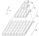
- FIG. 3 conceptually shows hierarchical data of moving images to be processed in the present embodiment.
- the hierarchical data has a hierarchical structure including a 0th hierarchy 30, a first hierarchy 32, a second hierarchy 34, and a third hierarchy 36 in the z-axis direction from the top to the bottom of the figure.
- each layer includes moving image data representing one moving image at different resolutions, that is, data in which a plurality of image frames are arranged in time series.
- each layer is symbolically represented by four image frames, but the number of image frames naturally varies depending on the playback time and frame rate of the moving image.
- the present embodiment is excellent in random accessibility to a three-dimensional space on the image plane and time axis of moving image data. Therefore, for example, by regarding the time axis as “depth”, three-dimensional volume data may be processed instead of moving image data.
- the type of parameter is not particularly limited as long as the data can have redundancy in the three-dimensional direction.
- the hierarchical data has a hierarchical structure of a quadtree, and when the image frames constituting each hierarchy are divided into “tile images” having the same size, the 0th hierarchy 30 is one tile image, and the first hierarchy 32 Is 2 ⁇ 2 tile images, the second layer 34 is 4 ⁇ 4 tile images, the third layer is 8 ⁇ 8 tile images, and the like.
- the resolution of the Nth layer (N is an integer of 0 or more) is 1 ⁇ 2 of the resolution of the (N + 1) th layer in both the left and right (x-axis) directions and the vertical (y-axis) direction on the image plane.
- Hierarchical data can be generated by reducing an image frame in a plurality of stages based on a moving image of the third hierarchy 36 having the highest resolution.
- the viewpoint coordinates at the time of moving image display and the corresponding display area are a virtual three-dimensional space composed of an x-axis representing the horizontal direction of the image, a y-axis representing the vertical direction, and a z-axis representing the resolution.
- x-axis representing the horizontal direction of the image
- y-axis representing the vertical direction
- z-axis representing the resolution.
- the image processing apparatus 10 basically draws image frames in any hierarchy sequentially at a predetermined frame rate along the time axis t. For example, a moving image having a resolution of the 0th hierarchy 30 is displayed as a reference image. If a display area movement request signal is supplied from the input device 20 in the process, the change amount of the display image is derived from the signal, and the coordinates of the four corners of the next frame in the virtual space (frame coordinates) are used by using the change amount. ) Is derived. Then, an image frame corresponding to the frame coordinates is drawn. At this time, by providing a layer switching boundary with respect to the z-axis, the layer of moving image data used for frame drawing is appropriately switched according to the value of z of the frame coordinates.
- the image processing apparatus 10 may derive information for specifying a hierarchy and texture coordinates (UV coordinates) in the hierarchy.
- texture coordinates UV coordinates
- the combination of the hierarchy specifying information and the texture coordinates is also referred to as frame coordinates.
- the hierarchical data is held in the storage device in a compressed state in a predetermined compression format. Data necessary for frame drawing is read from the storage device and decoded.
- FIG. 3 conceptually represents hierarchical data, and does not limit the storage order or format of data stored in the storage device. For example, if the position of the hierarchical data in the virtual space is associated with the storage area for the actual moving image data, the moving image data can be stored in an arbitrary area. As will be described later, space division or time division may be applied to the image frame sequence constituting each layer, and compression coding may be performed in that unit.
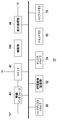
- FIG. 4 shows the configuration of the image processing apparatus 10.
- the image processing apparatus 10 includes a wireless interface 40, a switch 42, a display processing unit 44, a hard disk drive 50, a recording medium mounting unit 52, a disk drive 54, a main memory 60, a buffer memory 70, and a control unit 100.
- the display processing unit 44 has a frame memory that buffers data to be displayed on the display of the display device 12.
- the switch 42 is an Ethernet switch (Ethernet is a registered trademark), and is a device that transmits and receives data by connecting to an external device in a wired or wireless manner.
- the switch 42 is connected to an external network via the cable 14 and configured to receive hierarchical data from the image server.
- the switch 42 is connected to the wireless interface 40, and the wireless interface 40 is connected to the input device 20 using a predetermined wireless communication protocol.
- a display area movement request signal input from the user by the input device 20 is supplied to the control unit 100 via the wireless interface 40 and the switch 42.
- the hard disk drive 50 functions as a storage device that stores data.
- the hierarchical data may be stored in the hard disk drive 50.
- the recording medium mounting unit 52 reads data from the removable recording medium.
- the disk drive 54 drives and recognizes the ROM disk to read data.
- the ROM disk may be an optical disk or a magneto-optical disk.
- Hierarchical data may be stored in these recording media.
- the control unit 100 includes a multi-core CPU, and has one general-purpose processor core and a plurality of simple processor cores in one CPU.
- the general-purpose processor core is called PPU (Power Processing Unit), and the remaining processor cores are called SPU (Synergistic-Processing Unit).
- the control unit 100 may further include a GPU (Graphics Processing Unit).
- the control unit 100 includes a memory controller connected to the main memory 60 and the buffer memory 70.
- the PPU has a register, has a main processor as an operation execution subject, and efficiently assigns a task as a basic processing unit in an application to be executed to each SPU. Note that the PPU itself may execute the task.
- the SPU has a register, and includes a sub-processor as an operation execution subject and a local memory as a local storage area. The local memory may be used as the buffer memory 70.
- the main memory 60 and the buffer memory 70 are storage devices and are configured as a RAM (Random Access Memory).
- the SPU has a dedicated DMA (Direct Memory Access) controller as a control unit, can transfer data between the main memory 60 and the buffer memory 70 at high speed, and the frame memory and the buffer memory 70 in the display processing unit 44 High-speed data transfer can be realized.
- the control unit 100 according to the present embodiment realizes a high-speed image processing function by operating a plurality of SPUs in parallel.
- the display processing unit 44 is connected to the display device 12 and outputs an image processing result according to a request from the user.
- the image processing apparatus 10 sequentially transfers moving image data spatially and temporally close to the currently displayed frame from the hard disk drive 50 to the main memory in order to smoothly perform enlargement / reduction processing and scroll processing of the display image. 60 is loaded. Further, a part of the moving image data loaded in the main memory 60 is decoded and stored in the buffer memory 70. As a result, the display area can be smoothly moved while moving picture reproduction is progressing. At this time, the data to be loaded or decoded may be determined by pre-reading the necessary area based on the movement direction of the display area so far.
- the position in the z-axis direction indicates the resolution.
- the position closer to the 0th hierarchy 30 has a lower resolution, and the position closer to the third hierarchy 36 has a higher resolution.
- the position in the z-axis direction corresponds to the scale ratio.
- the scale ratio of the display image of the third hierarchy 36 is 1
- the scale ratio in the second hierarchy 34 is 1.
- the scale factor in the first hierarchy 32 is 1/16
- the scale factor in the 0th hierarchy 30 is 1/64.
- the display image when the display image changes in the direction from the 0th layer 30 side to the third layer 36 side, the display image expands and the direction from the third layer 36 side to the 0th layer 30 side. In the case of changing to, the display image is reduced. For example, when the scale ratio of the display image is in the vicinity of the second hierarchy 34, the display image is created using the image data of the second hierarchy 34.
- a switching boundary is provided for each intermediate scale ratio of each layer.
- the second hierarchy 34 when the scale ratio of the image to be displayed is between the switching boundary between the first hierarchy 32 and the second hierarchy 34 and the switching boundary between the second hierarchy 34 and the third hierarchy 36, the second hierarchy 34.
- a frame is drawn using the image data.
- the image frame of the second hierarchy 34 is scaled and displayed.
- the image frame of the second layer 34 is enlarged and displayed.
- the scale ratio of each layer is set as a prefetch boundary. For example, at least a part of the image data of the first hierarchy 32 in the reduction direction is transferred from the hard disk drive 50 or the main memory 60 when the requested scale ratio by the display area movement request signal crosses the scale ratio of the second hierarchy 34. Read ahead, decode and write to buffer memory 70.
- a prefetch boundary is set for the image data developed in the buffer memory 70, and the prefetch process is started when the display position by the image change request signal crosses the prefetch boundary.
- FIG. 5 shows in detail the configuration of the control unit 100a having a function of displaying moving images using moving image data having a hierarchical structure in the present embodiment.
- the control unit 100a includes an input information acquisition unit 102 that acquires information input by the user from the input device 20, a frame coordinate determination unit 110 that determines frame coordinates of a region to be newly displayed, and compression of a video stream to be newly loaded.
- a load stream determination unit 106 that determines data and a load unit 108 that loads a necessary moving image stream from the hard disk drive 50 are included.
- the control unit 100a further includes a decoding unit 112 that decodes the compressed data of the moving image stream, and a display image processing unit 114 that draws an image frame.
- each element described as a functional block for performing various processes can be constituted by a CPU (Central Processing Unit), a memory, and other LSIs in terms of hardware. Specifically, it is realized by a program loaded in a memory.
- the control unit 100 includes one PPU and a plurality of SPUs, and each functional block can be configured by the PPU and the SPU individually or in cooperation. Therefore, it is understood by those skilled in the art that these functional blocks can be realized in various forms by hardware only, software only, or a combination thereof, and is not limited to any one.
- the input information acquisition unit 102 acquires request contents such as start / end of moving image reproduction, movement of the display area, and the like input by the user to the input device 20 and notifies the frame coordinate determination unit 110 of them.
- the frame coordinate determination unit 110 determines the frame coordinates of a region to be newly displayed in accordance with the frame coordinates of the current display region and the display region movement request signal input by the user, the load stream determination unit 106, the decoding unit 112, the display
- the image processing unit 114 is notified.
- the load stream determination unit 106 Based on the frame coordinates notified from the frame coordinate determination unit 110, the load stream determination unit 106 identifies compressed video data to be newly loaded from the hard disk drive 50 to the main memory 60, and issues a load request to the load unit 108. Issue.
- the hierarchical data of the present embodiment individually holds a moving image stream for each tile image sequence obtained by spatially dividing the frame image sequence constituting each layer into the same size.
- the load stream determination unit 106 acquires necessary moving image stream identification information. If the compressed data of the corresponding video stream has not been loaded, a load request is issued to the load unit 108. Further, even if the frame coordinates do not change, it is requested that the compressed data of the necessary moving image stream is sequentially loaded according to the progress of the moving image.
- the load stream determination unit 106 identifies a video stream that is predicted to be necessary in addition to the video stream necessary for frame drawing at that time by the pre-read process described above, and issues a load request to the load unit 108. Good.
- the load stream determination unit 106 may make a load request at a predetermined timing in a state where the load unit 108 is not performing the load process, for example, at a predetermined time interval or when the user inputs a display area movement request.
- the load unit 108 performs load processing from the hard disk drive 50 in accordance with a request from the load stream determination unit 106. Specifically, the storage area is specified from the identification information of the moving picture stream to be loaded, and the data read from the storage area is stored in the main memory 60.
- the decoding unit 112 reads and decodes the necessary moving picture stream data from the main memory 60 based on the frame coordinates at each time, and sequentially stores them in the buffer memory 70.
- the decoding target may be a moving image stream unit, and when the frame coordinate area determined by the frame coordinate determining unit 110 extends over a plurality of moving image streams, the plurality of moving image streams are decoded.
- the display image processing unit 114 reads the data of the corresponding image frame from the buffer memory 70 based on the frame coordinates at each time, and draws it in the frame memory of the display processing unit 44.
- the unit for generating the moving image stream and the overall configuration are It can be appropriately changed according to the compression method and the content of the moving image.
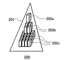
- 6 to 9 show examples of the structure of moving image data to be processed in the present embodiment.
- the triangle represents the hierarchical data of the moving image
- the rectangular parallelepiped represents one moving image stream.
- Each hierarchical data consists of three hierarchies of the zeroth hierarchy, the first hierarchy, and the second hierarchy, but the number of hierarchies is not limited to that.
- one moving image stream is generated for each tile image obtained by dividing the image frame of each layer into the same size.
- the size of the 0th layer image is set as the size of the tile image.
- the moving image data structure 200 shown in FIG. 6 includes one layer data 201 in which each layer is one moving image stream for each tile image from the start to the end of the moving image.
- the 0th layer is one moving image stream 202a
- the first layer is 4 moving image streams 202b
- the second layer is 16 The video stream 202c and the like.
- the length of the moving image stream in the time direction varies depending on the length of the original moving image, that is, the number of original image frames. Therefore, it is advantageous when the number of image frames is originally small, or when a compression method capable of long-term data compression and random access, for example, MPEG (Moving Picture Experts Group) using all frames as I pictures is used. It is.
- MPEG Motion Picture Experts Group
- the moving picture data structure 204 shown in FIG. 7 is composed of one hierarchical data 205 in which the moving picture data is divided by a predetermined number of image frames, and each hierarchy is a plurality of moving picture streams in the time axis direction for each tile image. That is, the moving image stream in FIG. 6 is obtained by dividing each moving image stream shown in FIG. 6 with respect to the time axis which is the vertical direction of the drawing. In this example, the moving picture stream of FIG. 6 is divided into six moving picture streams. Therefore, the 0th layer is composed of 1 ⁇ 6 moving image streams 206a, the first layer is composed of 4 ⁇ 6 moving image streams 206b, the second layer is composed of 16 ⁇ 6 moving image streams 206c, and the like. This structure is used when a compression method that performs compression in units of a fixed number of image frames is used.
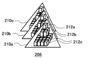
- the moving image data structure 208 shown in FIG. 8 has a configuration in which moving image data is divided by a predetermined number of image frames, and different hierarchical data 210a, 210b, and 210c are generated for each moving image stream generated in that unit. That is, each hierarchical data 210a, 210b, 210c is composed of one moving image stream in the time axis direction for each layer as in FIG. 6, but each moving image stream has a fixed number of image frames. For example, in the hierarchical data 210a, the 0th layer is composed of one moving image stream 212a, the first layer is composed of 4 moving image streams 212b, and the second layer is composed of 16 moving image streams 212c.
- the moving picture data structure 208 in FIG. 8 since it is composed of a plurality of hierarchical data in the time axis direction, only a certain scene is replaced with another hierarchical data, or hierarchical data is inserted or deleted. Easy video editing in any direction.
- the data size is easy to estimate.
- the data of each moving picture stream can have the same structure as the data of the tile image when the still picture has the same hierarchical structure. Coexistence with a still image such as an image display or a partial image as a still image is facilitated.
- the moving picture data structure 214 shown in FIG. 9 has a configuration in which the moving picture data is divided by a predetermined number of image frames, and the moving picture stream generated in that unit is further divided into a predetermined number of pieces to form different hierarchical data 216a, 216b, and 216c. That is, each hierarchical data 216a, 216b, 216c is composed of a plurality of moving image streams in the time axis direction for each layer as in FIG. 7, but the number is fixed regardless of the length of the moving image. In this case, the hierarchy data is divided by using two.
- the 0th layer includes 1 ⁇ 2 moving image streams 218a
- the first layer includes 4 ⁇ 2 moving image streams 218b
- the second layer includes 16 ⁇ 2 moving image streams 218c. Also in this case, it is easy to estimate and adjust the data size of each layer constituting one layer data, and it is easy to edit a moving image in the time axis direction by replacing the layer data.
- FIGS. 6 to 9 all retain the moving image stream so as to cover the entire area of the image frame in each layer. However, some moving image streams depend on the redundancy of the moving image. May be omitted from the moving image data and replaced with a moving image stream of a different level.
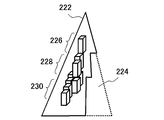
- FIG. 10 schematically shows the data structure of a moving image when a moving image stream of a part of the hierarchy is replaced with a moving image stream of another layer. The way of representing the data structure is the same as in FIG. In the hierarchical data 222 shown in the figure, the moving picture stream corresponding to the area 224 is omitted.
- the number of moving picture streams is smaller in the first hierarchy 228 and the second hierarchy 230. This is a video stream from which this difference is omitted.
- the area represented by the omitted moving image stream has no data in the hierarchy. Therefore, when displaying the corresponding area at a scale ratio that should use data of such a hierarchy, the hierarchy is held up to the hierarchy holding the data of the applicable area, in the example of FIG. And draw.
- Such an aspect can be applied to a case where there is an area that does not require detailed information in the image frame, for example, an area composed of almost a single color such as sky, sea, or lawn.
- the presence or absence of redundancy in the image frame can be detected by image analysis. For example, for each image frame at each time, a difference image between an image obtained by enlarging an image frame on the low resolution side and an image on the high resolution side is generated, and an area where the difference value is equal to or less than a predetermined threshold is detected. . Then, among the video streams included in the area, the high-resolution layer video stream is excluded from the video data.
- the size of the moving image data can be kept small, and a part of the loading processing of the moving image stream can be omitted.
- identification of the moving image stream of the upper layer used in an enlarged manner with respect to the coordinates of the area corresponding to the excluded moving image stream Drawing is possible by associating information and adding information such as an enlargement ratio.
- FIG. 10 is a mode that is realized by the present embodiment having both the feature that the moving image data has a hierarchical structure and the feature that the frame image is spatially divided and the moving image stream is individually generated.
- the data retention format can be locally changed, and data with a lower resolution can be used instead, so some data is omitted.
- Data size can be reduced.
- only a part of moving image streams may be thinned out to reduce the number of image frames, thereby reducing the data size.
- the time resolution of the area handled by the moving picture stream is reduced, it is effective for moving pictures including areas with little temporal change such as the background.
- the temporal redundancy at this time can be specified by, for example, detecting a region having a difference value equal to or less than a predetermined threshold among the difference images between adjacent image frames.
- some moving picture streams can be replaced with still images.
- the compression method may be different for each video stream.
- various image representations can be realized by intentionally shifting the time axis in predetermined units such as for each hierarchy, for each moving picture stream, for each pixel column in the image. It may be.
- the hierarchical structure of the moving image data to be displayed in the present embodiment is not particularly limited with respect to the compression method of each moving image stream, such as JPEG (Joint Photographic Experts Group), MPEG, S3TC (S3 Texture Compression), etc. Any of the existing methods may be applied. However, in order to enable seamless movement of the display area, including layer switching, spatial and random access is possible, and both image quality and decoding throughput are maintained even for high-definition images. It is desirable to be able to do it.
- JPEG Joint Photographic Experts Group
- MPEG Joint Photographic Experts Group
- S3TC S3 Texture Compression
- a method for compressing a moving picture stream in units of a fixed number of image frames which can be applied to the moving picture data structure shown in FIGS.
- the compression method can be applied not only to a plurality of moving image streams constituting hierarchical data but also to a single moving image stream.
- An apparatus that implements this compression technique can also be realized with the same configuration as the image processing apparatus 10 shown in FIG. Hereinafter, the description will be given focusing on the configuration of the control unit 100.
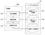
- FIG. 11 shows in detail the configuration of the control unit 100b having the moving image data compression function and the hard disk drive 50 in the present embodiment.
- the control unit 100b includes a YCbCr conversion unit 120 that converts a color space of an image frame constituting a moving image stream to be compressed into YCbCr, an image division unit 122 that generates a coding unit by space-time dividing the converted image sequence, and A compression encoding unit 124 that performs compression encoding processing by quantizing the image data for each of the divided encoding units is included.
- the hard disk drive 50 includes a moving image stream storage unit 126 that stores a moving image stream to be compressed including individual image frame sequences, a division pattern storage unit 128 that stores division patterns when the image dividing unit 122 divides the image sequence, and A compressed data storage unit 130 for storing compressed data generated by compression encoding by the compression encoding unit 124 is included.
- the YCbCr conversion unit 120 sequentially reads out the data of the image frames constituting the moving image stream to be compressed from the moving image stream storage unit 126. Then, by converting the RGB value, which is the pixel value of each image frame, into luminance Y and color differences Cb and Cr, a Y image, a Cb image, and a Cr image having the respective values as pixel values are generated.
- An existing method can be applied to the conversion of the color space from RGB to YCbCr. Since a Y image, a Cb image, and a Cr image are generated from one image frame, a Y image sequence, a Cb image sequence, and a Cr image sequence are generated for a plurality of image frames that form a moving image stream.
- the image dividing unit 122 first reduces each Cb image and Cr image at a predetermined ratio among the Y image sequence, Cb image sequence, and Cr image sequence generated by the YCbCr conversion unit 120. Then, the Y image sequence, the Cb image sequence, and the Cr image sequence are spatiotemporally divided by the division patterns stored in the division pattern storage unit 128. A unit generated by the division is referred to as “coding unit”.
- the image division unit 122 may perform a process of selecting an optimum pattern from a plurality of division patterns stored in the division pattern storage unit 128. .
- the Cb image and the Cr image reduced in the subsequent processing are handled as a set for each corresponding frame.
- such a set of Cb image and Cr image is simply referred to as “CbCr image”.
- the compression encoding unit 124 includes a palette representing two representative values for each encoding unit of the Y image and the CbCr image, and a plurality of intermediate values obtained by linearly interpolating the two representative values and the representative value. By generating an index that designates either one for each pixel, the image data is quantized and compression-coded. Thereby, a palette and an index are generated for each encoding unit of the Y image sequence and each encoding unit of the CbCr image sequence.
- FIG. 12 schematically illustrates a moving image stream compression procedure performed by the image processing apparatus 10 including the control unit 100b.
- the moving image stream 250 to be compressed may correspond to, for example, a moving image stream indicated by a rectangular parallelepiped in FIGS.
- the moving image stream 250 is composed of image frames of RGB images.
- the moving picture stream 250 is compressed every predetermined number of image frames, that is, every 8 frames in the example of FIG.
- the YCbCr conversion unit 120 further divides the image frame for eight frames into a predetermined size and determines a processing unit in a three-dimensional space of the image plane (x, y) and the time axis t.
- data of 8 pixels ⁇ 8 pixels ⁇ 8 frames is used as a processing unit 252.
- eight Y image sequences 254 and CbCr image sequences 256 are generated from the eight RGB images included in the processing unit 252 (S10).
- the CbCr image sequence 256 is an image sequence obtained by reducing the Cb image and Cr image directly obtained from the original RGB image to 1/2 size in both the vertical and horizontal directions. Therefore, the Y image row 254 has 8 image frames of 8 pixels ⁇ 8 pixels, and the CbCr image row 256 has 8 frames of images obtained by connecting a Cb image of 4 pixels ⁇ 4 pixels and a Cr image of 4 pixels ⁇ 4 pixels. .
- the image dividing unit 122 performs space-time division on the Y image sequence 254 and the CbCr image sequence 256 with any one of the division patterns stored in the division pattern storage unit 128 to form a coding unit (S12). ).
- a coding unit S12
- an image block obtained by spatially dividing each image frame of the Y image sequence 254 and the CbCr image sequence 256 with the same size of 4 horizontal pixels ⁇ 2 vertical pixels is divided into two images adjacent in the time direction. Data of 4 pixels ⁇ 2 pixels ⁇ 2 pieces divided for each frame is used as an encoding unit.
- each image frame has “A”, “B”, “C”, “D”, “E”, “F”, “G”, “ The image block “A” is divided into eight image blocks “H”, and the image block “A” of the first frame and the image block “A” of the second frame form an encoding unit 258 (shaded area). The same applies to the other image blocks and image frames.
- the CbCr image sequence 256 is 4 pixels ⁇ 4 pixels for both the Cb image and the Cr image, the former is divided into two image blocks of “I” and “J”, and the latter of “K” and “L”.
- the image blocks “I” and “K” of the first frame and the image blocks “I” and “K” of the second frame form an encoding unit 260 (shaded area).
- the compression encoding unit 124 generates palette and index data for each encoding unit.
- the palette and the index are basically the same as the palette and the index generated from the RGB image in the S3TC texture compression method.
- the number of parameter dimensions is different from that of general S3TC.
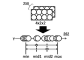
- FIG. 13 schematically shows a method for generating palette and index data from the encoding unit 258 of the Y image sequence 254.
- the luminance Y value that internally divides the line segment between the minimum value and the maximum value by 1: 2 is the first intermediate value (mid1), and the luminance Y value that is internally divided by 2: 1.
- the second intermediate value (mid2) data that stores information specifying any one of the four values of the minimum value, the first intermediate value, the second intermediate value, and the maximum value is used as an index.
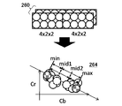
- FIG. 14 schematically shows a method of generating palette and index data from the encoding unit 260 of the CbCr image sequence 256.
- 2 representative values are selected.
- the color difference at the left end and the right end of the straight line is set as a representative value as a minimum value (min) and a maximum value (max), respectively.
- the data holding the binary values is set as a palette.
- each representative value is a two-dimensional parameter having (color difference Cb, color difference Cr) as an element.
- the color difference that internally divides the line segment between the minimum value and the maximum value by 1: 2 is the first intermediate value (mid1)
- the color difference that internally divides by 2: 1 is the second intermediate value (mid2).
- data that stores information specifying any one of the four values of the minimum value, the first intermediate value, the second intermediate value, and the maximum value is used as an index.
- an RGB image of 8 pixels ⁇ 8 pixels ⁇ 8 frames in one processing unit is 256 in total, including a palette of 64 bytes and an index of 128 bytes for a Y image sequence, and a palette of 32 bytes and an index of 32 bytes for a CbCr image sequence. It becomes a byte. That is, the data is 0.5 bytes per pixel.
- the index is information representing the identification numbers of 4 values of RGB values as 0 to 3
- the RGB image is decomposed into a Y image that holds a one-dimensional parameter and a CbCr image that holds a two-dimensional parameter, and then a palette and an index are generated. Therefore, in the case of a one-dimensional Y image, all sample values are distributed on a straight line, and in a two-dimensional CbCr image, the sample deviating from the approximate line is only in the normal direction of the approximate line. Therefore, compared with a general S3TC method in which an RGB image holding three-dimensional parameters is approximated by a straight line and quantized, the quantization error can be suppressed small.
- FIG. 15 shows a variation of a pattern for dividing one processing unit. Pattern (A), pattern (B), pattern (C), and pattern (D) are shown from the left end of the figure, and each of the upper Y image sequence and the lower CbCr image sequence indicates a space division delimiter with a straight line.
- One coding unit is represented by shading.
- Pattern (A) is a pattern divided into 4 horizontal pixels ⁇ 4 vertical pixels ⁇ 1 frame.
- the pattern (B) is the same as the pattern shown in FIG.
- Pattern (C) is a pattern divided into 2 horizontal pixels ⁇ vertical 2 pixels ⁇ 4 frames
- pattern (D) is a pattern divided into 2 horizontal pixels ⁇ 1 vertical pixel ⁇ 8 frames.
- each of these patterns since one processing unit is 16 pixels for the Y image sequence and 16 pixels ⁇ 2 for the CbCr image sequence, the number of samples at the time of quantization is as shown in FIG. 13 and FIG. The same.
- the more detailed time division is performed from the pattern (D) to the pattern (A)
- the more detailed space division is performed from the pattern (A) to the pattern (D).
- Such a division pattern is prepared, and the division pattern is selected according to the characteristics of the image, such as whether it has redundancy in the spatial direction or redundancy in the temporal direction.
- the image has spatial redundancy, such as the sky and turf contain many areas close to a single color, the pixel values tend to be more uniform with respect to the space, and the number of space divisions can be reduced. Since an error due to quantization is difficult to be included, a divided pattern close to the pattern (A) is selected.
- the image has temporal redundancy, such as when a fixed-point view of a scene with little motion is observed, the pixel values are likely to be uniform in the time direction, and even if the number of time divisions is reduced, errors due to quantization are not easily included. Therefore, a division pattern close to the pattern (D) is selected.
- one coding unit has only two pixels in the spatial direction. If there is no time change for 8 frames included in the same encoding unit, the two representative values held in the palette represent the original pixel values as they are, and the quantization error is zero.
- the RGB image is compressed by the S3TC method, the RGB data held in the palette is reduced from the original 24 bits to 16 bits, so that sufficient gradation cannot be obtained when decoding, such as image quality. A decrease may occur.
- an 8-bit palette is prepared for each of the luminance Y and the color differences Cb and Cr, so that there is a high possibility that the original image quality can be maintained.
- the division pattern storage unit 128 stores four types of division patterns (A) to (D) and information for identifying them, for example, four identification numbers 0, 1, 2, and 3 in association with each other. Keep it.
- the image division unit 122 performs all the division patterns stored in the division pattern storage unit 128 for each image sequence generated by the YCbCr conversion unit 120, and selects a division pattern with the least error from the original image.
- this processing causes the compression encoding unit 124 to perform compression encoding of the image sequence when divided by each division pattern, and compares the image obtained by decoding each compressed data with the image before compression for each image frame. To do. Then, a division pattern with a small difference may be selected.
- the image dividing unit 122 notifies the identification number of the selected division pattern to the compression encoding unit 124, and the compression encoding unit 124 includes the information of the identification number in the generated compressed data as final compressed data. And stored in the compressed data storage unit 130.
- the division pattern may be different for each region in the image.
- the procedure for selecting the division pattern for each region may be the same as described above.
- the image division unit 122 generates a map in which the identification number of the selected division pattern is associated with the region, and includes the map in the final compressed data.
- FIG. 16 shows an example of the data structure of the division pattern map. The example in the figure shows a case where one moving picture stream is composed of image frames of 256 pixels ⁇ 256 pixels.
- the minimum unit that can set the division pattern is 8 pixels ⁇ 8 pixels ⁇ 8 frames, which is one processing unit.
- the example of FIG. 16 is a case where the division pattern is set for each minimum unit of 8 pixels ⁇ 8 pixels. Similarly, for example, every 16 pixels ⁇ 16 pixels, every 64 pixels ⁇ 32 pixels, etc. A division pattern may be set for each region obtained by connecting regions of 8 pixels ⁇ 8 pixels in the direction. Also, the setting unit itself can be set variously, such as setting one division pattern for all the areas.
- the division pattern map can be generated by decoding the data that was actually compressed and encoded as described above and with a small error from the original image. In addition, the division pattern map can be set by the test image having the same contents and the division pattern set there You may have prepared.
- the compressed data generated in the present embodiment is composed of palettes and indexes as in the S3TC texture compression method. Therefore, the decoding process can use a general GPU shading function included in the control unit 100 of the image processing apparatus 10 of FIG. 4 as it is.
- the index and palette generated by quantizing the data of the Y image sequence and the index and palette generated by quantizing the data of the CbCr image sequence can be read and decoded in the same manner as a normal texture image. It is desirable to do. Therefore, when storing compressed data, the quantized data of the Y image sequence and the quantized data of the CbCr image sequence representing the same region are combined into one, so that the pixels can be restored with a small number of data accesses.
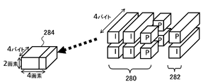
- FIG. 17 is a diagram for explaining the arrangement of compressed data in the compressed data storage unit 130.
- the compressed data 280 for the Y image sequence and the compressed data 282 for the CbCr image sequence representing the same area are collected as one storage unit.
- the rectangular parallelepiped denoted as “I” is generated from one encoding unit
- the rectangular parallelepiped denoted as “P” is generated from one encoding unit. It is a pallet.
- the compressed data 282 for the CbCr image sequence As described above, the index and palette of the Y image sequence are 4 bytes and 2 bytes of data per encoding unit, respectively. Both the index and palette of the CbCr image sequence are 4 bytes of data per encoding unit.
- each palette is 2-byte data, so by arranging two in the depth direction as shown in the figure, 2 ⁇ 4 ⁇ 4 bytes of data in the vertical direction. It becomes.
- the Y image sequence and the CbCr image sequence representing the same area are, for example, the image blocks “A”, “B”, “C”, “D” of the Y image and the image block “I” of the Cb image in FIG. , The image block “K” of the Cr image.
- the compressed data When the compressed data is collected in this way, it can be stored as it is in the storage area 284 for storing RGBA image data of 2 pixels in the vertical direction ⁇ 4 pixels in the horizontal direction.
- 32 encoding units are formed for the Y image sequence and 8 encoding units are formed for the CbCr image sequence per processing unit of 8 pixels ⁇ 8 pixels ⁇ 8 frames, so that there are 8 storage units per processing unit.
- Individually formed Since one storage unit has the same data size as an RGBA image of 2 pixels in the vertical direction and 4 pixels in the horizontal direction, the data is equivalent to an RGBA image of 8 pixels ⁇ 8 pixels per processing unit. This feature is the same for any division pattern shown in FIG.
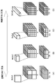
- FIG. 18 schematically shows the transition of data when the compression encoding process described so far is applied to the entire moving picture stream.
- the moving image stream is composed of image frames of RGB images of 256 pixels ⁇ 256 pixels and is compressed in units of 8 frames.
- 8 image frames are divided into processing units of 8 pixels ⁇ 8 pixels (S20). As a result, 32 processing units are formed in the vertical and horizontal directions.
- YCbCr conversion is performed on each processing unit to generate a Y image and a reduced CbCr image, and each is divided into coding units, and an index and a palette are generated.
- eight storage units are generated per processing unit (S22). As a result, the RGB images for 8 frames are compressed into 1 frame of RGBA image having the same number of pixels.
- each palette stores binary values that are representative values of luminance Y. Therefore, 2-bit information for identifying the four division patterns is embedded using two palettes arranged side by side in the depth direction among the four palettes included in one storage unit.
- FIG. 19 is a diagram for explaining a method of embedding the identification number of the division pattern in the two pallets.
- the two values held by the first pallet 290 are “Pa0” and “Pa1” in order from the head address in the front of the figure, and the two values held by the second pallet 292 are “Pb0” in the address order.
- information of 2 bits in total is represented by the magnitude relationship between “Pa0” and “Pa1” and the magnitude relationship between “Pb0” and “Pb1”.
- 1-bit information is represented by “1” if “Pa0” of the first pallet 290 is larger than “Pa1” and “0” otherwise.
- Pb0 of the second pallet 292 is larger than “Pb1”
- “1” is set, and “0” is expressed otherwise.
- the binary value held by the palette does not affect the decoding process, whichever is stored at the previous address. Therefore, the identification number of the divided pattern can be embedded in the pallet by changing the address in which the larger value is stored in each pallet according to the identification number of the divided pattern.
- the division pattern map can be included in the compressed data without being generated separately from the main body of the compressed data, and the data size can be suppressed as a whole.
- the efficiency in referring is good.
- the same division pattern may be embedded in all 16 pairs of pallets included in the eight storage units.
- the Y image sequence palette in which the division pattern is embedded is read, and the identification number of the division pattern set in the processing unit To identify.
- the pixel can be associated with the storage location of the index and pallet containing the data necessary for drawing the pixel. Accordingly, the index and palette of the Y image sequence and the index and palette of the CbCr image sequence corresponding to the drawing target pixel may be read and decoded.
- Decoding processing can be basically performed in the same manner as S3TC. That is, an intermediate value that interpolates the representative value held by each palette is generated, and the representative value or the intermediate value is set as the pixel value of each pixel according to the designation in the index.
- the determined pixel value is based on the arrangement of the encoding units in the image sequence corresponding to the division pattern, and in the spatial direction and the temporal direction.
- the Y image sequence and the CbCr image sequence are restored by reconstructing the pixel arrangement. Then, by enlarging the CbCr image to generate a Cb image and a Cr image, a YCbCr image corresponding to the original image frame is obtained.
- hierarchical data is generated by hierarchizing a plurality of video streams representing image frames constituting a video at different resolutions, and the display area is moved in response to a viewpoint movement request from the user. To display the video.
- the hierarchy of data used for frame drawing according to the required scale ratio, even a general high-definition image or a moving image with a resolution higher than that can be enlarged to confirm details or have a bird's-eye view. Requests can be sequentially received and displayed with good responsiveness.
- the video stream that configures each layer of the layer data is configured with image frames of the same size in any layer.
- the higher the resolution the greater the number of video streams that make up one hierarchy.
- the entire moving image may not be composed of one hierarchical data, but may be divided on the time axis to be composed of a plurality of hierarchical data.
- the moving picture stream of each layer included in one hierarchical data may be one moving picture compressed data over the entire volume, or may be different moving picture compressed data for each predetermined number of image frames.
- the processing load when displaying moving images can be selected by appropriately selecting the number of hierarchical data, the data structure of the video stream in the hierarchical data, and the compression encoding format depending on the content of the moving image and the playback time. Therefore, an optimum display mode can be realized from various viewpoints such as required image quality.
- the moving image stream is compression-coded for every predetermined number of image frames.
- an image in which the RGB image of the image frame constituting the original moving image stream is represented by luminance Y, color difference Cb, and Cr is generated.
- each image sequence is divided into a predetermined size and a predetermined number of image frames to generate a coding unit.
- palette and index data are generated for each of the Y image sequence and the CbCr image sequence.
- the palette is binary data representing the representative value of each image
- the index is data for designating one of the intermediate value and representative value obtained by linear interpolation of the representative value for each pixel.
- the concept of palette and index is introduced in the S3TC compression method for texture RGB images, but in this embodiment, the binary value of the palette is 8 bits for all of luminance Y, color difference Cb, and color difference Cr. Image quality is unlikely to deteriorate due to retention.
- the quantization is separately performed on the Y image sequence and the CbCr image sequence, the number of parameter dimensions is smaller and the quantization error is smaller than when the RGB three-dimensional parameters are quantized.
- the rendering process can be performed in the same manner as the texture mapping process by the GPU. Therefore, the video stream in the display area is read while the hierarchy is switched, and the image is rendered at a predetermined frame rate. High throughput that can be applied to hierarchically structured video data can be expected.
- the processing load of decoding tends to increase depending on the content of the image.
- MPEG requires decoding of I pictures for each of a plurality of moving picture streams. As a result, the processing load tends to increase, and if I pictures are reduced, there is a problem that latency tends to occur for random access in the time direction. .
- the compression encoding technique in the present embodiment realizes high-speed drawing as compared with the above existing technique by realizing decoding with GPU. As a result, a high-definition moving image can be displayed while reducing the processing load on the CPU. For this reason, it is possible to perform additional processing in the CPU, and the risk of dropping frames is reduced even in a device such as a portable terminal having inferior CPU processing performance. This feature can be said to be suitable for future technological trends in which data reading from a storage device is accelerated with the spread of SSD (Solid Sate Drive) and decoding processing is likely to become a bottleneck.
- SSD Solid Sate Drive
- this compression coding technology can achieve high-throughput rendering while maintaining image quality, and also enables temporal and spatial random access with low latency, so high-definition video can be displayed while changing the display area.
- 1 image processing system 10 image processing device, 12 display device, 20 input device, 30 0th layer, 32 1st layer, 34 2nd layer, 36 3rd layer, 44 display processing unit, 50 hard disk drive, 60 main memory , 70 buffer memory, 100 control unit, 102 input information acquisition unit, 106 load stream determination unit, 108 load unit, 110 frame coordinate determination unit, 112 decoding unit, 114 display image processing unit, 120 YCbCr conversion unit, 122 image division unit , 124 compression encoding unit, 126 video stream storage unit, 128 division pattern storage unit, 130 compressed data storage unit.
- the present invention is applicable to information processing apparatuses such as computers, image processing apparatuses, image display apparatuses, and data compression apparatuses.
Landscapes
- Engineering & Computer Science (AREA)
- Multimedia (AREA)
- Signal Processing (AREA)
- Theoretical Computer Science (AREA)
- Physics & Mathematics (AREA)
- General Physics & Mathematics (AREA)
- General Engineering & Computer Science (AREA)
- Human Computer Interaction (AREA)
- Compression Or Coding Systems Of Tv Signals (AREA)
- Controls And Circuits For Display Device (AREA)
- Processing Or Creating Images (AREA)
Abstract
Selon la présente invention, des données vidéo sont agencées selon une structure en couches qui comprend, dans la direction de l'axe z et depuis le haut vers le bas du dessin, une couche zéro (30), une première couche (32), une deuxième couche (34) et une troisième couche (36). Chaque couche est constituée par des données vidéo et elle est caractérisée en ce qu'une seule image vidéo est représentée par différentes résolutions ; en d'autres termes, une seule image vidéo est représentée par des données dans lesquelles une pluralité de trames d'image est agencée en une série chronologique. Quand une vidéo est affichée, des coordonnées de point de vue et une zone d'affichage correspondant à ces coordonnées sont définies par un espace virtuel en 3D qui comprend : l'axe x, qui représente la direction horizontale d'une image ; l'axe y, qui représente la direction verticale de l'image ; et l'axe z, qui représente la résolution. En prévoyant des limites de commutation pour les couches qui sont en relation avec l'axe z, la couche de données vidéo utilisée pour le rendu d'une trame est commutée sur la base de la valeur z des coordonnées de la trame.
Priority Applications (5)
| Application Number | Priority Date | Filing Date | Title |
|---|---|---|---|
| CN201180043291.7A CN103098466B (zh) | 2010-09-13 | 2011-07-06 | 图像处理装置和图像处理方法 |
| EP18150093.5A EP3334161B1 (fr) | 2010-09-13 | 2011-07-06 | Dispositif de traitement d'images, procédé de traitement d'images et structure de données d'un fichier d'image animée |
| EP11824711.3A EP2618565A4 (fr) | 2010-09-13 | 2011-07-06 | Dispositif de traitement d'image, procédé de traitement d'image, structure de données pour fichiers vidéo, dispositif de compression de données, dispositif de décodage de données, procédé de compression de données, procédé de décodage de données et structure de données pour fichiers vidéo compressés |
| US13/782,185 US9218640B2 (en) | 2010-09-13 | 2013-03-01 | Image processing device for displaying moving image and image processing method thereof |
| US14/940,527 US9607357B2 (en) | 2010-09-13 | 2015-11-13 | Image processing device for displaying moving image and image processing method thereof |
Applications Claiming Priority (4)
| Application Number | Priority Date | Filing Date | Title |
|---|---|---|---|
| JP2010204806A JP5484276B2 (ja) | 2010-09-13 | 2010-09-13 | データ圧縮装置、データ復号装置、データ圧縮方法、データ復号方法、および圧縮動画像ファイルのデータ構造 |
| JP2010-204805 | 2010-09-13 | ||
| JP2010-204806 | 2010-09-13 | ||
| JP2010204805A JP5544253B2 (ja) | 2010-09-13 | 2010-09-13 | 画像処理装置、画像処理方法、および動画像ファイルのデータ構造 |
Related Child Applications (1)
| Application Number | Title | Priority Date | Filing Date |
|---|---|---|---|
| US13/782,185 Continuation US9218640B2 (en) | 2010-09-13 | 2013-03-01 | Image processing device for displaying moving image and image processing method thereof |
Publications (1)
| Publication Number | Publication Date |
|---|---|
| WO2012035691A1 true WO2012035691A1 (fr) | 2012-03-22 |
Family
ID=45831187
Family Applications (1)
| Application Number | Title | Priority Date | Filing Date |
|---|---|---|---|
| PCT/JP2011/003871 WO2012035691A1 (fr) | 2010-09-13 | 2011-07-06 | Dispositif de traitement d'image, procédé de traitement d'image, structure de données pour fichiers vidéo, dispositif de compression de données, dispositif de décodage de données, procédé de compression de données, procédé de décodage de données et structure de données pour fichiers vidéo compressés |
Country Status (4)
| Country | Link |
|---|---|
| US (2) | US9218640B2 (fr) |
| EP (2) | EP3334161B1 (fr) |
| CN (1) | CN103098466B (fr) |
| WO (1) | WO2012035691A1 (fr) |
Cited By (1)
| Publication number | Priority date | Publication date | Assignee | Title |
|---|---|---|---|---|
| WO2013099076A1 (fr) * | 2011-12-27 | 2013-07-04 | 株式会社ソニー・コンピュータエンタテインメント | Appareil de compression d'image en mouvement, appareil de traitement d'image, procédé de compression d'image en mouvement, procédé de traitement d'image, et structure de données de fichier d'image en mouvement compressé |
Families Citing this family (29)
| Publication number | Priority date | Publication date | Assignee | Title |
|---|---|---|---|---|
| JP5548671B2 (ja) * | 2011-12-27 | 2014-07-16 | 株式会社ソニー・コンピュータエンタテインメント | 画像処理システム、画像提供サーバ、情報処理装置、および画像処理方法 |
| US9979960B2 (en) * | 2012-10-01 | 2018-05-22 | Microsoft Technology Licensing, Llc | Frame packing and unpacking between frames of chroma sampling formats with different chroma resolutions |
| US9967559B1 (en) | 2013-02-11 | 2018-05-08 | Google Llc | Motion vector dependent spatial transformation in video coding |
| US9544597B1 (en) | 2013-02-11 | 2017-01-10 | Google Inc. | Hybrid transform in video encoding and decoding |
| US9674530B1 (en) | 2013-04-30 | 2017-06-06 | Google Inc. | Hybrid transforms in video coding |
| JP2017513358A (ja) * | 2014-03-17 | 2017-05-25 | ノキア テクノロジーズ オサケユイチア | ビデオのエンコーディングおよびデコーディングのための方法およびテクノロジー機器 |
| EP3135036B1 (fr) * | 2014-05-23 | 2021-07-07 | HFI Innovation Inc. | Procédé et appareil pour la prédiction et la signalisation de table de palette |
| US10136141B2 (en) * | 2014-06-11 | 2018-11-20 | Qualcomm Incorporated | Determining quantization parameter (QP) values and delta QP values for palette coded blocks in video coding |
| US10687064B2 (en) * | 2014-08-04 | 2020-06-16 | Qualcomm Incorporated | Palette mode encoding and decoding with inferred pixel scan order |
| US9565451B1 (en) | 2014-10-31 | 2017-02-07 | Google Inc. | Prediction dependent transform coding |
| US9466124B2 (en) | 2014-11-10 | 2016-10-11 | Intel Corporation | Compression using index bits in MSAA |
| AU2015345649A1 (en) * | 2014-11-12 | 2017-06-08 | Hfi Innovation Inc. | Methods of escape pixel coding in index map coding |
| US20160283483A1 (en) * | 2015-03-27 | 2016-09-29 | Google Inc. | Providing selected images from a set of images |
| US9769499B2 (en) | 2015-08-11 | 2017-09-19 | Google Inc. | Super-transform video coding |
| US10535114B2 (en) * | 2015-08-18 | 2020-01-14 | Nvidia Corporation | Controlling multi-pass rendering sequences in a cache tiling architecture |
| US10277905B2 (en) | 2015-09-14 | 2019-04-30 | Google Llc | Transform selection for non-baseband signal coding |
| US9986135B2 (en) * | 2015-11-13 | 2018-05-29 | Texas Instruments Incorporated | Spatially localized cluster compression |
| US9892542B2 (en) * | 2015-11-19 | 2018-02-13 | Adobe Systems Incorporated | Creating bump and normal maps from images with multi-scale control |
| US9807423B1 (en) | 2015-11-24 | 2017-10-31 | Google Inc. | Hybrid transform scheme for video coding |
| MX2018006642A (es) * | 2015-12-14 | 2018-08-01 | Panasonic Ip Corp America | Metodo de codificacion de datos tridimencionales, metodos de decodificacion de datos tridimensionales, dispositivo de codificacion de datos tridimensionales y dispositivo de decodificacion de datos tridimensionales. |
| US10552717B2 (en) * | 2016-03-16 | 2020-02-04 | Canon Kabushiki Kaisha | Image processing apparatus, control method thereof, and storage medium |
| CN114359487A (zh) * | 2016-09-16 | 2022-04-15 | 松下电器(美国)知识产权公司 | 三维数据制作方法以及三维数据制作装置 |
| JP6840506B2 (ja) * | 2016-10-20 | 2021-03-10 | キヤノン株式会社 | 画像処理装置、画像処理方法、プログラム |
| US20190342609A1 (en) * | 2017-01-16 | 2019-11-07 | Sony Semiconductor Solutions Corporation | Transmission control apparatus, reception control apparatus, and transceiving control system |
| CN108010112B (zh) * | 2017-11-28 | 2023-08-22 | 腾讯数码(天津)有限公司 | 动画处理方法、装置及存储介质 |
| CN111221924B (zh) * | 2018-11-23 | 2023-04-11 | 腾讯科技(深圳)有限公司 | 一种数据处理方法、装置、存储介质和网络设备 |
| JP2022051967A (ja) * | 2019-01-08 | 2022-04-04 | ソニーグループ株式会社 | 情報処理装置および情報処理方法 |
| US11122297B2 (en) | 2019-05-03 | 2021-09-14 | Google Llc | Using border-aligned block functions for image compression |
| CN110662071B (zh) * | 2019-09-27 | 2023-10-24 | 腾讯科技(深圳)有限公司 | 视频解码方法和装置、存储介质及电子装置 |
Citations (7)
| Publication number | Priority date | Publication date | Assignee | Title |
|---|---|---|---|---|
| JPH11265461A (ja) * | 1998-03-18 | 1999-09-28 | Matsushita Electric Ind Co Ltd | 動画像再生品質制御装置およびその制御方法 |
| US6563999B1 (en) | 1997-03-27 | 2003-05-13 | Sony Computer Entertainment, Inc. | Method and apparatus for information processing in which image data is displayed during loading of program data, and a computer readable medium and authoring system therefor |
| JP2003317110A (ja) * | 2002-04-23 | 2003-11-07 | Nippon Telegr & Teleph Corp <Ntt> | 3次元動画像データの提供方法とその表示方法、該提供装置と該表示端末、該方法の実行プログラム、および該方法の実行プログラムを記録した記録媒体 |
| JP2003348562A (ja) * | 2002-05-27 | 2003-12-05 | Telecommunication Advancement Organization Of Japan | Cg画像配信システム |
| JP2004234476A (ja) * | 2003-01-31 | 2004-08-19 | Toshiba Corp | 画像データ符号化方式、画像データ復号化方式、および画像データ復号化装置 |
| WO2005059836A1 (fr) * | 2003-12-19 | 2005-06-30 | Telefonaktiebolaget Lm Ericsson (Publ) | Traitement d'images |
| WO2006006915A1 (fr) * | 2004-07-08 | 2006-01-19 | Telefonaktiebolaget Lm Ericsson (Publ) | Traitement d'images multimodal |
Family Cites Families (7)
| Publication number | Priority date | Publication date | Assignee | Title |
|---|---|---|---|---|
| CN1140126C (zh) * | 1995-06-29 | 2004-02-25 | 汤姆森多媒体公司 | 分层压缩视频数据的编解码系统 |
| US6819793B1 (en) * | 2000-06-30 | 2004-11-16 | Intel Corporation | Color distribution for texture and image compression |
| JP4371982B2 (ja) * | 2004-11-08 | 2009-11-25 | キヤノン株式会社 | 画像処理装置及びその制御方法、並びに、コンピュータプログラム及びコンピュータ可読記憶媒体 |
| US7714873B2 (en) * | 2006-06-29 | 2010-05-11 | Microsoft Corporation | Strategies for compressing textures |
| JP4835554B2 (ja) | 2007-09-06 | 2011-12-14 | ソニー株式会社 | 符号化装置及び方法、復号装置及び方法、並びにプログラム |
| GB2457646B (en) * | 2007-10-30 | 2010-03-03 | Imagination Tech Ltd | Method and apparatus for compressing and decompressing data |
| JP4978598B2 (ja) * | 2008-09-17 | 2012-07-18 | コニカミノルタビジネステクノロジーズ株式会社 | 画像処理方法、画像処理装置、および画像処理プログラム |
-
2011
- 2011-07-06 WO PCT/JP2011/003871 patent/WO2012035691A1/fr active Application Filing
- 2011-07-06 EP EP18150093.5A patent/EP3334161B1/fr active Active
- 2011-07-06 EP EP11824711.3A patent/EP2618565A4/fr not_active Ceased
- 2011-07-06 CN CN201180043291.7A patent/CN103098466B/zh active Active
-
2013
- 2013-03-01 US US13/782,185 patent/US9218640B2/en active Active
-
2015
- 2015-11-13 US US14/940,527 patent/US9607357B2/en active Active
Patent Citations (7)
| Publication number | Priority date | Publication date | Assignee | Title |
|---|---|---|---|---|
| US6563999B1 (en) | 1997-03-27 | 2003-05-13 | Sony Computer Entertainment, Inc. | Method and apparatus for information processing in which image data is displayed during loading of program data, and a computer readable medium and authoring system therefor |
| JPH11265461A (ja) * | 1998-03-18 | 1999-09-28 | Matsushita Electric Ind Co Ltd | 動画像再生品質制御装置およびその制御方法 |
| JP2003317110A (ja) * | 2002-04-23 | 2003-11-07 | Nippon Telegr & Teleph Corp <Ntt> | 3次元動画像データの提供方法とその表示方法、該提供装置と該表示端末、該方法の実行プログラム、および該方法の実行プログラムを記録した記録媒体 |
| JP2003348562A (ja) * | 2002-05-27 | 2003-12-05 | Telecommunication Advancement Organization Of Japan | Cg画像配信システム |
| JP2004234476A (ja) * | 2003-01-31 | 2004-08-19 | Toshiba Corp | 画像データ符号化方式、画像データ復号化方式、および画像データ復号化装置 |
| WO2005059836A1 (fr) * | 2003-12-19 | 2005-06-30 | Telefonaktiebolaget Lm Ericsson (Publ) | Traitement d'images |
| WO2006006915A1 (fr) * | 2004-07-08 | 2006-01-19 | Telefonaktiebolaget Lm Ericsson (Publ) | Traitement d'images multimodal |
Non-Patent Citations (1)
| Title |
|---|
| See also references of EP2618565A4 |
Cited By (3)
| Publication number | Priority date | Publication date | Assignee | Title |
|---|---|---|---|---|
| WO2013099076A1 (fr) * | 2011-12-27 | 2013-07-04 | 株式会社ソニー・コンピュータエンタテインメント | Appareil de compression d'image en mouvement, appareil de traitement d'image, procédé de compression d'image en mouvement, procédé de traitement d'image, et structure de données de fichier d'image en mouvement compressé |
| JP2013135463A (ja) * | 2011-12-27 | 2013-07-08 | Sony Computer Entertainment Inc | 動画圧縮装置、画像処理装置、動画圧縮方法、画像処理方法、および動画圧縮ファイルのデータ構造 |
| US9693072B2 (en) | 2011-12-27 | 2017-06-27 | Sony Corporation | Moving picture compression apparatus, image processing apparatus, moving picture compression method, image processing method, and data structure of moving picture compression file |
Also Published As
| Publication number | Publication date |
|---|---|
| CN103098466B (zh) | 2016-08-17 |
| US20160071235A1 (en) | 2016-03-10 |
| EP3334161A1 (fr) | 2018-06-13 |
| EP2618565A4 (fr) | 2014-04-16 |
| CN103098466A (zh) | 2013-05-08 |
| US9607357B2 (en) | 2017-03-28 |
| EP2618565A1 (fr) | 2013-07-24 |
| EP3334161B1 (fr) | 2019-08-21 |
| US20130176211A1 (en) | 2013-07-11 |
| US9218640B2 (en) | 2015-12-22 |
Similar Documents
| Publication | Publication Date | Title |
|---|---|---|
| WO2012035691A1 (fr) | Dispositif de traitement d'image, procédé de traitement d'image, structure de données pour fichiers vidéo, dispositif de compression de données, dispositif de décodage de données, procédé de compression de données, procédé de décodage de données et structure de données pour fichiers vidéo compressés | |
| JP5722761B2 (ja) | 動画圧縮装置、画像処理装置、動画圧縮方法、画像処理方法、および動画圧縮ファイルのデータ構造 | |
| JP5826730B2 (ja) | 動画圧縮装置、画像処理装置、動画圧縮方法、画像処理方法、および動画圧縮ファイルのデータ構造 | |
| US11792405B2 (en) | Codec | |
| US6046773A (en) | Apparatus and method for decoding video images | |
| EP0771504B1 (fr) | Manipulation interactive d'images | |
| CN109983757A (zh) | 全景视频回放期间的视图相关操作 | |
| CN109983500A (zh) | 重新投影全景视频图片的平板投影以通过应用进行渲染 | |
| CN107465939B (zh) | 视频图像数据流的处理方法及装置 | |
| JP5544253B2 (ja) | 画像処理装置、画像処理方法、および動画像ファイルのデータ構造 | |
| AU2018233015A1 (en) | System and method for image processing | |
| JP3645922B2 (ja) | 画像処理方法及び装置 | |
| JP5484276B2 (ja) | データ圧縮装置、データ復号装置、データ圧縮方法、データ復号方法、および圧縮動画像ファイルのデータ構造 | |
| JP5520890B2 (ja) | 画像処理装置、画像データ生成装置、画像処理方法、画像データ生成方法、および画像ファイルのデータ構造 | |
| CN118015107A (zh) | 动态辐射场实时流式渲染方法、系统、设备、芯片及介质 | |
| JP4174026B2 (ja) | 画像処理装置 |
Legal Events
| Date | Code | Title | Description |
|---|---|---|---|
| WWE | Wipo information: entry into national phase |
Ref document number: 201180043291.7 Country of ref document: CN |
|
| 121 | Ep: the epo has been informed by wipo that ep was designated in this application |
Ref document number: 11824711 Country of ref document: EP Kind code of ref document: A1 |
|
| NENP | Non-entry into the national phase |
Ref country code: DE |
|
| WWE | Wipo information: entry into national phase |
Ref document number: 2011824711 Country of ref document: EP |