WO2012032965A1 - Cartouche de purification d'eau - Google Patents
Cartouche de purification d'eau Download PDFInfo
- Publication number
- WO2012032965A1 WO2012032965A1 PCT/JP2011/069538 JP2011069538W WO2012032965A1 WO 2012032965 A1 WO2012032965 A1 WO 2012032965A1 JP 2011069538 W JP2011069538 W JP 2011069538W WO 2012032965 A1 WO2012032965 A1 WO 2012032965A1
- Authority
- WO
- WIPO (PCT)
- Prior art keywords
- purification cartridge
- water
- water purification
- container
- raw water
- Prior art date
Links
- XLYOFNOQVPJJNP-UHFFFAOYSA-N water Substances O XLYOFNOQVPJJNP-UHFFFAOYSA-N 0.000 title claims abstract description 251
- 238000000746 purification Methods 0.000 title claims abstract description 83
- 239000008213 purified water Substances 0.000 claims abstract description 34
- 239000003463 adsorbent Substances 0.000 claims description 39
- 239000012510 hollow fiber Substances 0.000 claims description 20
- 239000012528 membrane Substances 0.000 claims description 20
- 239000011347 resin Substances 0.000 claims description 17
- 229920005989 resin Polymers 0.000 claims description 17
- 238000004382 potting Methods 0.000 claims description 10
- 238000007599 discharging Methods 0.000 claims description 6
- 238000011144 upstream manufacturing Methods 0.000 claims description 2
- 239000010419 fine particle Substances 0.000 abstract description 2
- OKTJSMMVPCPJKN-UHFFFAOYSA-N Carbon Chemical compound [C] OKTJSMMVPCPJKN-UHFFFAOYSA-N 0.000 description 32
- 239000000843 powder Substances 0.000 description 17
- 238000001914 filtration Methods 0.000 description 6
- 238000005192 partition Methods 0.000 description 6
- -1 residual chlorine Chemical class 0.000 description 6
- 239000000463 material Substances 0.000 description 4
- 239000008239 natural water Substances 0.000 description 4
- 238000001179 sorption measurement Methods 0.000 description 4
- VYPSYNLAJGMNEJ-UHFFFAOYSA-N Silicium dioxide Chemical compound O=[Si]=O VYPSYNLAJGMNEJ-UHFFFAOYSA-N 0.000 description 3
- 229910021536 Zeolite Inorganic materials 0.000 description 3
- 239000002250 absorbent Substances 0.000 description 3
- 230000002745 absorbent Effects 0.000 description 3
- HNPSIPDUKPIQMN-UHFFFAOYSA-N dioxosilane;oxo(oxoalumanyloxy)alumane Chemical compound O=[Si]=O.O=[Al]O[Al]=O HNPSIPDUKPIQMN-UHFFFAOYSA-N 0.000 description 3
- 239000002245 particle Substances 0.000 description 3
- 230000001681 protective effect Effects 0.000 description 3
- 239000010457 zeolite Substances 0.000 description 3
- 239000004698 Polyethylene Substances 0.000 description 2
- 239000004743 Polypropylene Substances 0.000 description 2
- BQCADISMDOOEFD-UHFFFAOYSA-N Silver Chemical compound [Ag] BQCADISMDOOEFD-UHFFFAOYSA-N 0.000 description 2
- 239000013522 chelant Substances 0.000 description 2
- 238000010586 diagram Methods 0.000 description 2
- 239000000835 fiber Substances 0.000 description 2
- 238000012856 packing Methods 0.000 description 2
- 229920003229 poly(methyl methacrylate) Polymers 0.000 description 2
- 229920000573 polyethylene Polymers 0.000 description 2
- 239000004926 polymethyl methacrylate Substances 0.000 description 2
- 229920000098 polyolefin Polymers 0.000 description 2
- 229920001155 polypropylene Polymers 0.000 description 2
- 230000000630 rising effect Effects 0.000 description 2
- 229910052709 silver Inorganic materials 0.000 description 2
- 239000004332 silver Substances 0.000 description 2
- ZCYVEMRRCGMTRW-UHFFFAOYSA-N 7553-56-2 Chemical compound [I] ZCYVEMRRCGMTRW-UHFFFAOYSA-N 0.000 description 1
- 241000894006 Bacteria Species 0.000 description 1
- ZAMOUSCENKQFHK-UHFFFAOYSA-N Chlorine atom Chemical compound [Cl] ZAMOUSCENKQFHK-UHFFFAOYSA-N 0.000 description 1
- VGGSQFUCUMXWEO-UHFFFAOYSA-N Ethene Chemical compound C=C VGGSQFUCUMXWEO-UHFFFAOYSA-N 0.000 description 1
- 239000005977 Ethylene Substances 0.000 description 1
- 239000004952 Polyamide Substances 0.000 description 1
- 239000004721 Polyphenylene oxide Substances 0.000 description 1
- 239000004372 Polyvinyl alcohol Substances 0.000 description 1
- 239000004809 Teflon Substances 0.000 description 1
- 229920006362 Teflon® Polymers 0.000 description 1
- 230000002378 acidificating effect Effects 0.000 description 1
- 230000000274 adsorptive effect Effects 0.000 description 1
- PNEYBMLMFCGWSK-UHFFFAOYSA-N aluminium oxide Inorganic materials [O-2].[O-2].[O-2].[Al+3].[Al+3] PNEYBMLMFCGWSK-UHFFFAOYSA-N 0.000 description 1
- 239000004760 aramid Substances 0.000 description 1
- 229920003235 aromatic polyamide Polymers 0.000 description 1
- 230000001580 bacterial effect Effects 0.000 description 1
- 229920002678 cellulose Polymers 0.000 description 1
- 239000001913 cellulose Substances 0.000 description 1
- 239000003795 chemical substances by application Substances 0.000 description 1
- 229910052801 chlorine Inorganic materials 0.000 description 1
- 239000000460 chlorine Substances 0.000 description 1
- 239000004927 clay Substances 0.000 description 1
- 229920001577 copolymer Polymers 0.000 description 1
- 230000000694 effects Effects 0.000 description 1
- 230000007613 environmental effect Effects 0.000 description 1
- 239000000499 gel Substances 0.000 description 1
- 229910052740 iodine Inorganic materials 0.000 description 1
- 239000011630 iodine Substances 0.000 description 1
- 238000005342 ion exchange Methods 0.000 description 1
- 239000003456 ion exchange resin Substances 0.000 description 1
- 229920003303 ion-exchange polymer Polymers 0.000 description 1
- 239000007769 metal material Substances 0.000 description 1
- 244000005700 microbiome Species 0.000 description 1
- 239000002808 molecular sieve Substances 0.000 description 1
- 229930014626 natural product Natural products 0.000 description 1
- 150000002894 organic compounds Chemical class 0.000 description 1
- 238000004806 packaging method and process Methods 0.000 description 1
- 239000002367 phosphate rock Substances 0.000 description 1
- 229920002492 poly(sulfone) Polymers 0.000 description 1
- 229920002239 polyacrylonitrile Polymers 0.000 description 1
- 229920002647 polyamide Polymers 0.000 description 1
- 239000004417 polycarbonate Substances 0.000 description 1
- 229920000515 polycarbonate Polymers 0.000 description 1
- 229920000728 polyester Polymers 0.000 description 1
- 229920000570 polyether Polymers 0.000 description 1
- 229920000642 polymer Polymers 0.000 description 1
- 229920001343 polytetrafluoroethylene Polymers 0.000 description 1
- 239000004810 polytetrafluoroethylene Substances 0.000 description 1
- 229920002451 polyvinyl alcohol Polymers 0.000 description 1
- 239000005373 porous glass Substances 0.000 description 1
- 239000011148 porous material Substances 0.000 description 1
- 238000007789 sealing Methods 0.000 description 1
- 239000000741 silica gel Substances 0.000 description 1
- 229910002027 silica gel Inorganic materials 0.000 description 1
- 239000000377 silicon dioxide Substances 0.000 description 1
- URGAHOPLAPQHLN-UHFFFAOYSA-N sodium aluminosilicate Chemical compound [Na+].[Al+3].[O-][Si]([O-])=O.[O-][Si]([O-])=O URGAHOPLAPQHLN-UHFFFAOYSA-N 0.000 description 1
- 239000008399 tap water Substances 0.000 description 1
- 235000020679 tap water Nutrition 0.000 description 1
- 238000003466 welding Methods 0.000 description 1
Images


Classifications
-
- B—PERFORMING OPERATIONS; TRANSPORTING
- B01—PHYSICAL OR CHEMICAL PROCESSES OR APPARATUS IN GENERAL
- B01D—SEPARATION
- B01D63/00—Apparatus in general for separation processes using semi-permeable membranes
- B01D63/02—Hollow fibre modules
- B01D63/024—Hollow fibre modules with a single potted end
-
- B—PERFORMING OPERATIONS; TRANSPORTING
- B01—PHYSICAL OR CHEMICAL PROCESSES OR APPARATUS IN GENERAL
- B01D—SEPARATION
- B01D61/00—Processes of separation using semi-permeable membranes, e.g. dialysis, osmosis or ultrafiltration; Apparatus, accessories or auxiliary operations specially adapted therefor
- B01D61/02—Reverse osmosis; Hyperfiltration ; Nanofiltration
- B01D61/08—Apparatus therefor
-
- B—PERFORMING OPERATIONS; TRANSPORTING
- B01—PHYSICAL OR CHEMICAL PROCESSES OR APPARATUS IN GENERAL
- B01D—SEPARATION
- B01D61/00—Processes of separation using semi-permeable membranes, e.g. dialysis, osmosis or ultrafiltration; Apparatus, accessories or auxiliary operations specially adapted therefor
- B01D61/14—Ultrafiltration; Microfiltration
- B01D61/18—Apparatus therefor
-
- C—CHEMISTRY; METALLURGY
- C02—TREATMENT OF WATER, WASTE WATER, SEWAGE, OR SLUDGE
- C02F—TREATMENT OF WATER, WASTE WATER, SEWAGE, OR SLUDGE
- C02F1/00—Treatment of water, waste water, or sewage
- C02F1/001—Processes for the treatment of water whereby the filtration technique is of importance
- C02F1/003—Processes for the treatment of water whereby the filtration technique is of importance using household-type filters for producing potable water, e.g. pitchers, bottles, faucet mounted devices
-
- B—PERFORMING OPERATIONS; TRANSPORTING
- B01—PHYSICAL OR CHEMICAL PROCESSES OR APPARATUS IN GENERAL
- B01D—SEPARATION
- B01D2313/00—Details relating to membrane modules or apparatus
- B01D2313/12—Specific discharge elements
-
- B—PERFORMING OPERATIONS; TRANSPORTING
- B01—PHYSICAL OR CHEMICAL PROCESSES OR APPARATUS IN GENERAL
- B01D—SEPARATION
- B01D2313/00—Details relating to membrane modules or apparatus
- B01D2313/40—Adsorbents within the flow path
-
- B—PERFORMING OPERATIONS; TRANSPORTING
- B01—PHYSICAL OR CHEMICAL PROCESSES OR APPARATUS IN GENERAL
- B01D—SEPARATION
- B01D2313/00—Details relating to membrane modules or apparatus
- B01D2313/44—Cartridge types
-
- B—PERFORMING OPERATIONS; TRANSPORTING
- B01—PHYSICAL OR CHEMICAL PROCESSES OR APPARATUS IN GENERAL
- B01D—SEPARATION
- B01D2313/00—Details relating to membrane modules or apparatus
- B01D2313/50—Specific extra tanks
-
- C—CHEMISTRY; METALLURGY
- C02—TREATMENT OF WATER, WASTE WATER, SEWAGE, OR SLUDGE
- C02F—TREATMENT OF WATER, WASTE WATER, SEWAGE, OR SLUDGE
- C02F1/00—Treatment of water, waste water, or sewage
- C02F1/28—Treatment of water, waste water, or sewage by sorption
- C02F1/281—Treatment of water, waste water, or sewage by sorption using inorganic sorbents
-
- C—CHEMISTRY; METALLURGY
- C02—TREATMENT OF WATER, WASTE WATER, SEWAGE, OR SLUDGE
- C02F—TREATMENT OF WATER, WASTE WATER, SEWAGE, OR SLUDGE
- C02F1/00—Treatment of water, waste water, or sewage
- C02F1/28—Treatment of water, waste water, or sewage by sorption
- C02F1/283—Treatment of water, waste water, or sewage by sorption using coal, charred products, or inorganic mixtures containing them
-
- C—CHEMISTRY; METALLURGY
- C02—TREATMENT OF WATER, WASTE WATER, SEWAGE, OR SLUDGE
- C02F—TREATMENT OF WATER, WASTE WATER, SEWAGE, OR SLUDGE
- C02F1/00—Treatment of water, waste water, or sewage
- C02F1/42—Treatment of water, waste water, or sewage by ion-exchange
-
- C—CHEMISTRY; METALLURGY
- C02—TREATMENT OF WATER, WASTE WATER, SEWAGE, OR SLUDGE
- C02F—TREATMENT OF WATER, WASTE WATER, SEWAGE, OR SLUDGE
- C02F1/00—Treatment of water, waste water, or sewage
- C02F1/44—Treatment of water, waste water, or sewage by dialysis, osmosis or reverse osmosis
-
- C—CHEMISTRY; METALLURGY
- C02—TREATMENT OF WATER, WASTE WATER, SEWAGE, OR SLUDGE
- C02F—TREATMENT OF WATER, WASTE WATER, SEWAGE, OR SLUDGE
- C02F2201/00—Apparatus for treatment of water, waste water or sewage
- C02F2201/002—Construction details of the apparatus
- C02F2201/006—Cartridges
-
- C—CHEMISTRY; METALLURGY
- C02—TREATMENT OF WATER, WASTE WATER, SEWAGE, OR SLUDGE
- C02F—TREATMENT OF WATER, WASTE WATER, SEWAGE, OR SLUDGE
- C02F2301/00—General aspects of water treatment
- C02F2301/04—Flow arrangements
-
- C—CHEMISTRY; METALLURGY
- C02—TREATMENT OF WATER, WASTE WATER, SEWAGE, OR SLUDGE
- C02F—TREATMENT OF WATER, WASTE WATER, SEWAGE, OR SLUDGE
- C02F2307/00—Location of water treatment or water treatment device
- C02F2307/04—Location of water treatment or water treatment device as part of a pitcher or jug
Definitions
- the present invention relates to a water purification cartridge and a water purifier provided with the same.
- a so-called pot type is known as a water purifier equipped with a water purification cartridge.
- This pot-type water purifier has a structure in which a water purification cartridge is interposed between a raw water storage part located on the upper side and a purified water storage part located on the lower side. The raw water stored in the raw water storage part flows into the purified water storage part through the water purification cartridge by its own weight, and is purified in the water purification cartridge.
- a water purification cartridge installed in a pot type water purifier for example, one described in Patent Document 1 can be cited.
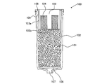
- Fig. 9 shows an example of a conventional water purification cartridge.
- an adsorbent 1001 and a hollow fiber membrane 1009 are arranged in a container as a filter medium.
- the container is mainly composed of a cylindrical case body 1002b that opens upward and accommodates a filter medium, and a cylindrical lid 1002a that closes the upper opening of the cylindrical case body 1002b.
- the cylindrical lid 1002a constitutes a space 1003 serving as an air collecting portion in the container, and an air outlet 1006 for discharging bubbles generated in the water purification cartridge is provided at the upper center of the cylindrical lid 1002a.
- a raw water inlet 1004 is provided on the side surface of the cylindrical lid 1002a.
- the hollow fiber membrane 1009 is fixed in the container by a potting resin 1010, and a purified water discharge port 1007 of purified water obtained by passing through the filter medium is provided below the potting resin 1010.
- FIG. 10 shows a schematic diagram of a pot-type water purifier 2000 including the water purification cartridge 1000 shown in FIG.
- the water purifier 2000 includes an inner container 2002 that configures the raw water storage unit 2004 and an outer container 2001 that configures the purified water storage unit 2003.
- the inner container 2002 has a cartridge housing portion 2002b, and the water purification cartridge 1000 is disposed in the cartridge housing portion 2002b.
- the raw water stored in the raw water storage part 2004 flows into the water purification cartridge from the raw water inlet and is purified through the water purification part in which the filter medium is arranged by its own weight.
- the obtained purified water flows from the purified water discharge port to the purified water storage unit 2003.
- the internal filter medium may leak from the raw water inlet when the water purification cartridge is transported.
- the water purification cartridge cannot be placed in close contact with the cartridge housing part, and the raw water flows out from the raw water storage part to the purified water storage part without passing through the inside of the water purification cartridge. Can be considered. Therefore, it is necessary to take protective measures to prevent fine powder from adhering to the fitting portion.
- Measures for such fine powder include, for example, covering the raw water supply port with a resin sheet or the like so that the fine powder does not leak to the outside. Moreover, even when fine powder leaks out, it can be mentioned that the fine powder is prevented from adhering to the fitting portion depending on the way of packing. However, these measures tend to increase packaging, and a water purification cartridge that can more easily take measures against fine powders has been demanded from an environmental point of view.
- an object of the present invention is to provide a water purification cartridge capable of easily taking measures against fine powder.
- the present invention is a water purification cartridge that is disposed between a raw water storage section and a purified water storage section of a water purifier and purifies raw water using a filter medium, and the container for storing the filter medium is directed to the inside on the upper surface.
- the water purification cartridge has a recessed portion that is recessed and has a raw water inlet for introducing the raw water into at least a side surface of the concave portion.
- this invention is a water purifier provided with the said water purification cartridge.
- the present invention relates to a water purification cartridge that is disposed between a raw water storage section and a purified water storage section of a water purifier and purifies the raw water using a filter medium.
- the container for storing the filter medium has a concave portion recessed toward the inside on the upper surface, and a raw water inlet for introducing the raw water into the inside is formed on at least a side surface of the concave portion. Yes. By setting it as such a structure, raw
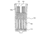
- FIG. 1 is a schematic cross-sectional view for explaining the configuration of the water purification cartridge of the present invention.
- the up-down direction of the water purification cartridge is described on the basis of the state arrange
- a water purification cartridge 100 has a container 102 that accommodates an adsorbent 101 as a filter medium for purifying raw water.
- a concave portion 103 is formed on the upper surface of the container 102, and a raw water inlet 104 for introducing raw water into the inside is formed on the side surface 103 a of the concave portion.
- the recess 103 is formed in the vicinity of the center of the upper surface of the container 102 so as to be recessed toward the inside of the container.
- an air discharge port 106 for discharging air such as bubbles generated in the container 102 to the outside is provided on the upper surface of the container 102. That is, the container 102 has the air discharge port 106 in the upper part of the space 105 formed between the concave side surface 103 a and the outer wall that forms the side surface of the container 102. Air such as bubbles generated in the container 102 accumulates in the space 105 between the side surface 103a of the recess and the outer side wall of the container 102, and is discharged outside through the air discharge port 106.
- the adsorbent 101 as a filter medium is disposed in the container 102 and below the bottom surface 103b of the recess.
- the adsorbent 101 is disposed in the container 102 by a partition wall 108 through which purified water can pass and can hold the adsorbent in the container.
- a purified water discharge port 107 for discharging purified water obtained by passing raw water through the adsorbent 101 is provided at the lower part of the container 102.
- Raw water enters the container 102 from the raw water inlet 104 formed in the concave side surface 103a.
- the raw water that has entered the container 102 flows downward due to its own weight and is purified by the adsorbent 101.
- the purified water from which the raw water is obtained through the adsorbent 101 flows out from the purified water discharge port 107 to the purified water storage section of the water purifier.
- the raw water can be gently supplied into the container.
- the filter medium is a material having a function of purifying raw water, and examples thereof include an adsorbent and a hollow fiber membrane.
- the adsorbent examples include a powder adsorbent, a granular adsorbent granulated from the powder adsorbent, or a fibrous adsorbent.
- adsorbents include natural product-based adsorbents (natural zeolite, silver zeolite, acidic clay, etc.) or synthetic-based adsorbents (synthetic zeolite, bacterial adsorption polymer, phosphate rock, molecular sieve, silica gel, silica And inorganic adsorbents such as alumina gel and porous glass.
- the activated carbon examples include powdered activated carbon, granular activated carbon, fibrous activated carbon, block activated carbon, extruded activated carbon, molded activated carbon, synthetic granular activated carbon, and synthetic activated carbon. Examples thereof include fibrous activated carbon.
- an organic adsorbent can also be used as the adsorbent.
- the organic adsorbent include molecular adsorption resins, ion exchange resins, ion exchange fibers, chelate resins, and chelate fibers. , Superabsorbent resin, superabsorbent resin, oil absorbent resin, oil absorbent and the like.
- activated carbon having excellent adsorptive power for organic compounds such as residual chlorine, mold odor, and trihalomethane in raw water is preferably used.
- the particle diameter at which the mass on the integrated sieve is 95% is 0.4 mm or more.
- the activated carbon those having properties with a packing density of 0.1 to 0.5 g / ml, an iodine adsorption amount of 800 to 4000 mg / g, and a particle size of 0.075 to 6.3 mm are preferable. Moreover, when silver is mixed with the activated carbon, the growth of bacteria and microorganisms can be suppressed.
- the mass of the activated carbon in the water purification cartridge can be in the range of 10 to 200 g, for example.
- the water purification cartridge may have a hollow fiber membrane 109 as a filter medium in addition to the adsorbent.
- the hollow fiber membrane 109 is fixed in the container using a potting resin 110 at the lower end of the container 102, and the end of the hollow fiber membrane 109 is opposite to the surface on the side where the potting resin filter medium is disposed. Open to the surface side.
- the potting resin 110 replaces the partition wall 108 in FIG.
- the arrangement of the adsorbent and the hollow fiber membrane is preferably a filter medium on the upstream side and a hollow fiber membrane on the downstream side, as shown in FIG.
- the hollow fiber membrane is not particularly limited.
- cellulose polyolefin (polyethylene, polypropylene), polyvinyl alcohol, ethylene / vinyl alcohol copolymer, polyether, polymethyl methacrylate (PMMA) ), Polysulfone, polyacrylonitrile, polytetrafluoroethylene (Teflon (registered trademark)), polycarbonate, polyester, polyamide, and aromatic polyamide.
- polyolefin-based hollow fiber membranes such as polyethylene and polypropylene are preferred.
- the hollow fiber membrane preferably has an outer diameter of 20 to 2000 ⁇ m, a pore diameter of 0.01 to 1 ⁇ m, a porosity of 20 to 90%, and a film thickness of 5 to 300 ⁇ m.
- the hollow fiber membrane is desirably a so-called hydrophilic hollow fiber membrane having a hydrophilic group on the surface.
- the recess 103 is formed on the upper surface of the container 102, and the raw water inlet 104 is formed on the side surface 103a of the recess.
- the raw water inlet is not particularly limited, but is preferably formed using a mesh member from the viewpoint of allowing raw water to pass through effectively and preventing the internal adsorbent from passing through or difficult to pass through.
- the material of the mesh member is not particularly limited.
- a material for the mesh member for example, a metal material or a resin material can be used. Further, it is preferable to use a mesh member having an opening smaller than the minimum particle size of the adsorbent.
- One or more raw water inlets can be provided on the side surface of the recess, and the opening is preferably enlarged so as not to hinder the filtration speed.
- the raw water inlet is preferably formed so that the lower end of the raw water inlet is at the same height as the bottom surface of the recess in order to introduce all the raw water in the raw water reservoir into the container.
- a space 105 is provided between the recess side surface 103a and the outer wall constituting the side surface of the container 102, and this space 105 serves as an air collecting portion for collecting air such as bubbles generated in the cartridge. .
- An air discharge port 106 for discharging the air accumulated in the space 105 is formed in the upper container portion of the space 105.
- the shape of the air outlet is not particularly limited, but may be, for example, a circular shape, an elliptical shape, or a polygonal shape, and may be an indefinite shape.
- the shape of the air discharge port 106 can be selected as appropriate.
- the diameter of the air discharge port can be 0.6 mm or more.
- air can be quickly discharged outside.
- it can select in consideration of the magnitude
- the above-mentioned diameter means the diameter in the case of a circular shape, the long diameter in the case of an elliptical shape, the longest diagonal line in the case of a polygon, and the widest width in the case of an indefinite shape.
- the shape of the container is not particularly limited, and may be, for example, a cylindrical shape, an elliptical column shape, a polygonal column shape, or the like.
- a container has a recessed part in the upper surface, ie, the upper surface at the time of arrange
- the recess is preferably provided at the center of the upper surface. By providing the recess in the center of the upper surface, the raw water can be supplied more evenly inside the container.
- One or more air outlets can be provided in the upper part of the recess.
- the arrangement of the air discharge ports is not particularly limited, but when a plurality of air discharge ports are provided, the air discharge ports can be provided in the upper portion of the recess so that the distances between the adjacent air discharge ports are equal to each other.
- 2 to 10 air outlets can be provided, 3 to 8 are preferably provided, and 4 to 6 are more preferably provided.
- the bottom surface 103b of the recess can reduce the bias of the filter medium accommodated in the container. For example, even when the cartridge is inclined, the bottom surface of the recess can reduce the bias of the filter medium, so that the occurrence of a short path can be suppressed. Moreover, since the unevenness of the filter medium can be reduced, the filter medium is less likely to come into contact with the raw water inlet, and the fine powder is less likely to leak from the raw water inlet.
- the difference between the outer diameter of the bottom surface of the recess and the inner diameter of the outer wall of the container is preferably 4 mm to 20 mm, more preferably 6 mm to 8 mm.
- the size (or volume) of the recess and the size (or volume) of the air collection unit can be selected as appropriate.
- the recessed part is formed smaller than the structure of FIG.
- the depth of the recess is preferably 20 mm or more, and more preferably 30 mm or more.
- the raw water inlet of the concave portion is disposed 10 mm or more from the bottom surface of the concave portion.
- FIG. 7 shows a configuration example of a water purifier provided with the water purification cartridge of the present invention.
- the water purifier 200 shown in FIG. 7 is a so-called pot type water purifier.
- the water purifier 200 is supplied with raw water such as tap water and stored therein, a water purification cartridge 100 attached to the bottom of the raw water storage unit 204, and the raw water storage unit 204 and the water purification cartridge 100 below. It forms a main body with the clean water storage part 203 located.
- the raw water stored in the raw water storage unit 204 is purified when passing through the purified water cartridge 100 by its own weight, and flows down to the purified water storage unit 203.
- the water purifier 200 includes a bottomed cylindrical outer container 201 having an open upper end, and a bottomed cylindrical inner container 202 having an open upper end that is inserted from the upper end opening of the outer container 201 and disposed in the outer container 201. It has.
- the inner container 202 is arranged at a depth of about half or less than the outer container 201, and the contents of the inner container 202 are fitted to the upper half of the outer container 201 without any gaps except for the predetermined gap 205.
- the raw water storage unit 204 is formed in the vessel 202.
- a purified water storage unit 203 is provided between the bottom wall 202 a of the inner container 202 and the bottom wall 201 a of the outer container 201.
- the gap 205 is formed so as to extend upward from the purified water storage unit 203 and functions as a pouring path when the purified water is poured.
- An upper lid portion 206 is fitted into the upper end opening of the inner container 202.
- the upper lid 206 may be provided with an openable / closable flap that opens a water supply port at the center and closes the water supply port from above.
- the opening formed at the upper end of the gap 205 functions as a spout, and a spout lid 207 is provided at the spout.
- the bottom wall 202a of the inner container is provided with a housing portion 202b for housing the water purification cartridge, and the bottom wall 202a of the inner container is formed with a gentle downward slope toward the housing portion 202b.
- the water purification cartridge housing portion 202b is recessed in the bottom wall 202a of the inner container toward the water purification storage portion.
- the water purification cartridge 100 is fitted into the housing portion 202b from above.
- the center of the bottom of the storage unit 202b is opened, and the raw water storage unit 204 and the purified water located below the storage unit 202b and the opening of the bottom, that is, through the water purification cartridge 100 attached to the storage unit 202b.
- the storage unit 203 communicates with the storage unit 203.
- the rising of fine powder can be suppressed.
- the water purification cartridge when the water purification cartridge is installed in the water purifier and the raw water is poured into the raw water storage part, the water flowing from the surroundings collides in the recess provided on the upper surface of the container, and the momentum of the water Can be reduced. Therefore, it is possible to suppress the rising of the fine powder when the raw water is poured in without reducing the filtration performance such as the filtration processing speed.
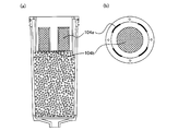
- a container 102 of the water purification cartridge 100 contains a filter medium, and forms a cylindrical case body 102b constituting a water purification unit, an upper lid 102a that closes an upper opening of the case 102b, and a lower end of the case body 102b.
- the lower lid 102c is mainly configured.
- the upper lid 102a has a concave portion 103 having a circular cross-sectional shape in the center, and the concave portion 103 enters the case body 102b when the upper lid 102a is connected to the case body 102b by the upper connecting portion 112.
- the absorbent 101 can be packed and accommodated up to the vicinity of the bottom surface 103b of the recess.
- the connection between the upper lid 102a and the case body 102b is not particularly limited, but for example, adhesion or welding can be used.
- positions a filter medium is comprised by the bottom face 103b of a recessed part, and the wall surface of a case body.
- a space 105 is provided between the recess side surface 103 a and the wall surface of the case body, and air such as bubbles in the cartridge flows into the space 105, and a part of the upper lid 102 a located above the space 105. Air is discharged from an air discharge port 106 provided in the.
- the side surface 103a of the recess is provided with a raw water inlet 104 for introducing the raw water into the water purification unit in the cartridge.
- the raw water introduced into the inside from the raw water introduction port 104 reaches the water purification unit where the adsorbent 101 is disposed through the space 105 by its own weight.
- the raw water inlet 104 is formed using a mesh-like member, and has a structure that allows raw water to pass through but does not allow the adsorbent to pass through.
- a partition wall 108 is provided below the case body 102b so as to hold the adsorbent 101 in the case body and allow purified water to pass therethrough.
- the water purification unit in which the adsorbent 101 is disposed includes the above-described recess bottom surface 103b, a case body wall surface, and a partition wall 108.
- a lower lid 102c having a purified water discharge port 107 is provided at the lower opening of the case body 102b.
- the lower lid 102c is connected to the case body 102b by a lower connecting portion 113.
- the purified water purified by the adsorbent 101 is discharged outside through a purified water discharge port 107 provided at the center of the lower part 102c.
- the lower lid 102c is formed to have a gentle downward slope toward the purified water discharge port 107.
- a groove structure for installing the elastic body 111 such as a gasket is provided on the side surface of the upper lid 102a so that the elastic body 111 is fitted tightly.
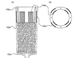
- FIG.4 (b) the structural example of the water purification cartridge incorporating a hollow fiber membrane is shown.
- the potting resin 110 has a function instead of the partition wall in FIG.
- the raw water inlet can also be provided on the bottom surface of the recess.
- the raw water inlet hereinafter also referred to as the first raw water inlet
- the raw water inlet hereinafter also referred to as the second raw water inlet
- Schematic of the water purification cartridge which has 104b is shown.
- the raw water inlet may be provided also on the bottom surface of the concave portion, and with such a configuration, raw water can be effectively supplied to the adsorbent below the concave bottom surface, Filtration efficiency can be increased.
- the raw water inlet can be 1 or more, and is preferably formed using a mesh member.
- FIG. 6 shows a schematic view of a water purification cartridge having a raw water inlet 104c (hereinafter also referred to as a third raw water inlet) provided on the side surface of the outer wall of the container in addition to the raw water inlet 104a provided on the side surface of the recess. .
- a third raw water introduction port may be provided on the side surface of the container.
- FIG. 8 shows a schematic diagram in which the water purification cartridge of the present embodiment is mounted on the water purifier 300.
- the third raw water inlet 104c is preferably formed at the height of the first raw water inlet 104a. Moreover, it is preferable that the lower end part of the 3rd raw
- the water purification cartridge of this embodiment is mounted in the water purifier so that the height of the upper end opening of the accommodating portion 302b and the lower end portion of the third raw water inlet 104c are the same.
- the water poured into the raw water reservoir 304 is supplied into the container from the first raw water inlet 104a and the third raw water inlet 104c.
Landscapes
- Chemical & Material Sciences (AREA)
- Engineering & Computer Science (AREA)
- Water Supply & Treatment (AREA)
- Chemical Kinetics & Catalysis (AREA)
- Nanotechnology (AREA)
- Life Sciences & Earth Sciences (AREA)
- Hydrology & Water Resources (AREA)
- Environmental & Geological Engineering (AREA)
- Organic Chemistry (AREA)
- Water Treatment By Sorption (AREA)
- Separation Using Semi-Permeable Membranes (AREA)
Abstract
La présente invention porte sur une cartouche de purification d'eau, à l'aide de laquelle il est possible de prendre facilement une mesure contre de fines particules. Cette cartouche de purification d'eau est destinée à être placée entre la partie de stockage d'eau brute et la partie de stockage d'eau purifiée d'un purificateur d'eau de façon à purifier ainsi l'eau brute à l'aide d'un milieu filtrant. La cartouche de purification d'eau comprend un récipient pour supporter le milieu filtrant à l'intérieur de celle-ci, le récipient ayant, dans la partie supérieure de celui-ci, une partie creuse qui fait saillie vers l'intérieur, et la partie creuse ayant, formée dans la paroi latérale de celle-ci, une ouverture d'introduction d'eau brute pour introduire l'eau brute dans l'intérieur.
Priority Applications (3)
| Application Number | Priority Date | Filing Date | Title |
|---|---|---|---|
| CN201180043448.6A CN103108835B (zh) | 2010-09-08 | 2011-08-30 | 净水滤筒 |
| JP2011539817A JP5433704B2 (ja) | 2010-09-08 | 2011-08-30 | 浄水カートリッジ |
| EP11823441.8A EP2615066A4 (fr) | 2010-09-08 | 2011-08-30 | Cartouche de purification d'eau |
Applications Claiming Priority (2)
| Application Number | Priority Date | Filing Date | Title |
|---|---|---|---|
| JP2010-201050 | 2010-09-08 | ||
| JP2010201050 | 2010-09-08 |
Publications (1)
| Publication Number | Publication Date |
|---|---|
| WO2012032965A1 true WO2012032965A1 (fr) | 2012-03-15 |
Family
ID=45810567
Family Applications (1)
| Application Number | Title | Priority Date | Filing Date |
|---|---|---|---|
| PCT/JP2011/069538 WO2012032965A1 (fr) | 2010-09-08 | 2011-08-30 | Cartouche de purification d'eau |
Country Status (4)
| Country | Link |
|---|---|
| EP (1) | EP2615066A4 (fr) |
| JP (1) | JP5433704B2 (fr) |
| CN (1) | CN103108835B (fr) |
| WO (1) | WO2012032965A1 (fr) |
Families Citing this family (4)
| Publication number | Priority date | Publication date | Assignee | Title |
|---|---|---|---|---|
| US9849407B2 (en) | 2013-07-12 | 2017-12-26 | Kx Technologies Llc | Carafe filter with air lock prevention feature |
| ITUB20154053A1 (it) * | 2015-09-30 | 2017-03-30 | Laica Spa | Dispositivo filtrante a percolazione |
| CN109982974B (zh) * | 2016-11-30 | 2021-10-29 | 东丽株式会社 | 净水器、净水器用支架及净水器用滤筒 |
| WO2018224517A1 (fr) | 2017-06-09 | 2018-12-13 | Brita Gmbh | Cartouche de traitement de liquide ainsi que système et procédé de fabrication et d'utilisation d'une cartouche de traitement de liquide |
Citations (5)
| Publication number | Priority date | Publication date | Assignee | Title |
|---|---|---|---|---|
| JPH11207320A (ja) * | 1998-01-26 | 1999-08-03 | Shoei Shalm Kk | 家庭用浄水器 |
| JP2003514647A (ja) | 1999-11-02 | 2003-04-22 | ブリタ ゲーエムベーハー | 液体用濾過装置 |
| JP2003260459A (ja) * | 2002-03-08 | 2003-09-16 | Nanasei Kk | 浄水器 |
| JP2005342684A (ja) * | 2004-06-07 | 2005-12-15 | New Medican Tech Kk | 浄水器用カートリッジ及びこれを用いた浄水器 |
| JP2006043609A (ja) * | 2004-08-05 | 2006-02-16 | Mitsubishi Rayon Co Ltd | 浄水カートリッジ |
Family Cites Families (6)
| Publication number | Priority date | Publication date | Assignee | Title |
|---|---|---|---|---|
| US4378293A (en) * | 1978-04-04 | 1983-03-29 | Duke Don T | Water filter |
| DE3535677A1 (de) * | 1985-10-05 | 1987-04-16 | Erich Alhaeuser | Patrone fuer ein drucklos arbeitendes geraet zur verbesserung der qualitaet von trinkwasser |
| US5300224A (en) * | 1991-11-21 | 1994-04-05 | Farley Frederick A | Fluid treatment device |
| CN2633864Y (zh) * | 2003-07-09 | 2004-08-18 | 李扬 | 水净化装置 |
| GB0707599D0 (en) * | 2007-04-19 | 2007-05-30 | Strix Ltd | Water treatment cartridges |
| JP2010162491A (ja) * | 2009-01-16 | 2010-07-29 | Panasonic Electric Works Co Ltd | 浄水カートリッジ及び浄水器 |
-
2011
- 2011-08-30 JP JP2011539817A patent/JP5433704B2/ja not_active Expired - Fee Related
- 2011-08-30 WO PCT/JP2011/069538 patent/WO2012032965A1/fr active Application Filing
- 2011-08-30 EP EP11823441.8A patent/EP2615066A4/fr not_active Withdrawn
- 2011-08-30 CN CN201180043448.6A patent/CN103108835B/zh not_active Expired - Fee Related
Patent Citations (5)
| Publication number | Priority date | Publication date | Assignee | Title |
|---|---|---|---|---|
| JPH11207320A (ja) * | 1998-01-26 | 1999-08-03 | Shoei Shalm Kk | 家庭用浄水器 |
| JP2003514647A (ja) | 1999-11-02 | 2003-04-22 | ブリタ ゲーエムベーハー | 液体用濾過装置 |
| JP2003260459A (ja) * | 2002-03-08 | 2003-09-16 | Nanasei Kk | 浄水器 |
| JP2005342684A (ja) * | 2004-06-07 | 2005-12-15 | New Medican Tech Kk | 浄水器用カートリッジ及びこれを用いた浄水器 |
| JP2006043609A (ja) * | 2004-08-05 | 2006-02-16 | Mitsubishi Rayon Co Ltd | 浄水カートリッジ |
Non-Patent Citations (1)
| Title |
|---|
| See also references of EP2615066A4 |
Also Published As
| Publication number | Publication date |
|---|---|
| CN103108835A (zh) | 2013-05-15 |
| EP2615066A4 (fr) | 2017-09-06 |
| EP2615066A1 (fr) | 2013-07-17 |
| JP5433704B2 (ja) | 2014-03-05 |
| CN103108835B (zh) | 2016-01-20 |
| JPWO2012032965A1 (ja) | 2014-01-20 |
Similar Documents
| Publication | Publication Date | Title |
|---|---|---|
| JP5582194B2 (ja) | 浄水カートリッジ及び浄水器 | |
| JP5999453B2 (ja) | 浄水カートリッジ | |
| JP5929194B2 (ja) | 自重濾過型浄水器 | |
| JP5757342B2 (ja) | 浄水カートリッジ、浄水器及びろ材 | |
| US20160136545A1 (en) | Water purification cartridge and water purifier | |
| JP5433704B2 (ja) | 浄水カートリッジ | |
| JP5609978B2 (ja) | 浄水カートリッジおよび浄水器 | |
| JP6679976B2 (ja) | 浄水カートリッジの製造方法 | |
| JP6447239B2 (ja) | 浄水カートリッジ | |
| JP5581645B2 (ja) | 浄水カートリッジおよび浄水器 | |
| JP2004050083A (ja) | 浄水器 | |
| KR20230162994A (ko) | 물 여과 시스템 | |
| JP2011115785A (ja) | 浄水カートリッジおよび浄水器 | |
| JP7141350B2 (ja) | 浄水カートリッジ | |
| JP2020069444A (ja) | 容器 | |
| JP2008136933A (ja) | 浄水カートリッジ |
Legal Events
| Date | Code | Title | Description |
|---|---|---|---|
| WWE | Wipo information: entry into national phase |
Ref document number: 201180043448.6 Country of ref document: CN |
|
| WWE | Wipo information: entry into national phase |
Ref document number: 2011539817 Country of ref document: JP |
|
| 121 | Ep: the epo has been informed by wipo that ep was designated in this application |
Ref document number: 11823441 Country of ref document: EP Kind code of ref document: A1 |
|
| NENP | Non-entry into the national phase |
Ref country code: DE |
|
| WWE | Wipo information: entry into national phase |
Ref document number: 2011823441 Country of ref document: EP |