WO2012029705A1 - 画像配信装置および方法 - Google Patents
画像配信装置および方法 Download PDFInfo
- Publication number
- WO2012029705A1 WO2012029705A1 PCT/JP2011/069426 JP2011069426W WO2012029705A1 WO 2012029705 A1 WO2012029705 A1 WO 2012029705A1 JP 2011069426 W JP2011069426 W JP 2011069426W WO 2012029705 A1 WO2012029705 A1 WO 2012029705A1
- Authority
- WO
- WIPO (PCT)
- Prior art keywords
- image
- dimensional
- terminal device
- display
- images
- Prior art date
- Legal status (The legal status is an assumption and is not a legal conclusion. Google has not performed a legal analysis and makes no representation as to the accuracy of the status listed.)
- Ceased
Links
Images


Classifications
-
- A—HUMAN NECESSITIES
- A61—MEDICAL OR VETERINARY SCIENCE; HYGIENE
- A61B—DIAGNOSIS; SURGERY; IDENTIFICATION
- A61B6/00—Apparatus or devices for radiation diagnosis; Apparatus or devices for radiation diagnosis combined with radiation therapy equipment
- A61B6/02—Arrangements for diagnosis sequentially in different planes; Stereoscopic radiation diagnosis
- A61B6/022—Stereoscopic imaging
-
- A—HUMAN NECESSITIES
- A61—MEDICAL OR VETERINARY SCIENCE; HYGIENE
- A61B—DIAGNOSIS; SURGERY; IDENTIFICATION
- A61B6/00—Apparatus or devices for radiation diagnosis; Apparatus or devices for radiation diagnosis combined with radiation therapy equipment
- A61B6/42—Arrangements for detecting radiation specially adapted for radiation diagnosis
- A61B6/4208—Arrangements for detecting radiation specially adapted for radiation diagnosis characterised by using a particular type of detector
- A61B6/4233—Arrangements for detecting radiation specially adapted for radiation diagnosis characterised by using a particular type of detector using matrix detectors
-
- A—HUMAN NECESSITIES
- A61—MEDICAL OR VETERINARY SCIENCE; HYGIENE
- A61B—DIAGNOSIS; SURGERY; IDENTIFICATION
- A61B6/00—Apparatus or devices for radiation diagnosis; Apparatus or devices for radiation diagnosis combined with radiation therapy equipment
- A61B6/50—Apparatus or devices for radiation diagnosis; Apparatus or devices for radiation diagnosis combined with radiation therapy equipment specially adapted for specific body parts; specially adapted for specific clinical applications
- A61B6/502—Apparatus or devices for radiation diagnosis; Apparatus or devices for radiation diagnosis combined with radiation therapy equipment specially adapted for specific body parts; specially adapted for specific clinical applications for diagnosis of breast, i.e. mammography
-
- H—ELECTRICITY
- H04—ELECTRIC COMMUNICATION TECHNIQUE
- H04N—PICTORIAL COMMUNICATION, e.g. TELEVISION
- H04N13/00—Stereoscopic video systems; Multi-view video systems; Details thereof
- H04N13/30—Image reproducers
- H04N13/398—Synchronisation thereof; Control thereof
-
- G—PHYSICS
- G06—COMPUTING OR CALCULATING; COUNTING
- G06F—ELECTRIC DIGITAL DATA PROCESSING
- G06F3/00—Input arrangements for transferring data to be processed into a form capable of being handled by the computer; Output arrangements for transferring data from processing unit to output unit, e.g. interface arrangements
- G06F3/14—Digital output to display device ; Cooperation and interconnection of the display device with other functional units
-
- G—PHYSICS
- G09—EDUCATION; CRYPTOGRAPHY; DISPLAY; ADVERTISING; SEALS
- G09G—ARRANGEMENTS OR CIRCUITS FOR CONTROL OF INDICATING DEVICES USING STATIC MEANS TO PRESENT VARIABLE INFORMATION
- G09G3/00—Control arrangements or circuits, of interest only in connection with visual indicators other than cathode-ray tubes
- G09G3/001—Control arrangements or circuits, of interest only in connection with visual indicators other than cathode-ray tubes using specific devices not provided for in groups G09G3/02 - G09G3/36, e.g. using an intermediate record carrier such as a film slide; Projection systems; Display of non-alphanumerical information, solely or in combination with alphanumerical information, e.g. digital display on projected diapositive as background
- G09G3/003—Control arrangements or circuits, of interest only in connection with visual indicators other than cathode-ray tubes using specific devices not provided for in groups G09G3/02 - G09G3/36, e.g. using an intermediate record carrier such as a film slide; Projection systems; Display of non-alphanumerical information, solely or in combination with alphanumerical information, e.g. digital display on projected diapositive as background to produce spatial visual effects
Definitions
- the present invention relates to an image distribution apparatus and method for distributing a stereoscopically viewable medical three-dimensional image to a terminal apparatus that has requested image distribution.
- stereoscopic viewing can be performed using parallax by displaying a combination of a plurality of images.
- a stereoscopically viewable image hereinafter referred to as a stereoscopic image or a three-dimensional image
- a stereoscopic image or a three-dimensional image is displayed based on a plurality of images with parallax obtained by photographing the same subject from different directions.
- Such 3D image display is used not only in the fields of digital cameras and televisions, but also in the field of radiographic imaging.
- radiation is irradiated to the subject from a reference position where the subject is viewed from the vertical direction and a reference position shifted from the reference position by a predetermined angle, and the radiation transmitted through the subject is detected by a radiation image detector.
- a plurality of radiation images having parallax with each other is acquired, and a three-dimensional image is displayed based on these radiation images.
- stereoscopic viewing is performed by three-dimensionally displaying the above-described plurality of radiation images or a three-dimensional image generated from the plurality of radiation images on a three-dimensional monitor for performing stereoscopic viewing.
- a monitor that can only perform two-dimensional display referred to as a two-dimensional monitor
- a three-dimensional image is displayed on a two-dimensional monitor, the image looks very double, and the image becomes very difficult to observe.
- an image that cannot be stereoscopically viewed that is, a two-dimensional image (for example, a radiation image used to generate a three-dimensional image) may be displayed instead of the three-dimensional image on the two-dimensional monitor.
- the image file includes a three-dimensional image
- three-dimensional display is performed using the three-dimensional image.
- the image file includes only the two-dimensional image, and therefore a method for displaying the two-dimensional image has been proposed (see Patent Document 1).
- a method of switching the image display mode to the two-dimensional display mode or the three-dimensional display mode based on the file identification information has also been proposed (see Patent Document 2).
- Patent Document 2 when a request for image distribution is made from a terminal device that can store images on a server and can only perform two-dimensional display, and the image is a three-dimensional image, There has also been proposed a method for preventing delivery of a three-dimensional image. Further, Patent Document 3 proposes a method of acquiring a suitable three-dimensional image by three-dimensionally converting a two-dimensional image based on a recognition result of display capability and a recognition result of an image to be displayed.
- the method described in Patent Document 1 performs three-dimensional display when the image file includes a three-dimensional image, and the image file that performs three-dimensional display includes only a three-dimensional image. is there.
- the technique described in Patent Document 2 also has a display mode in the two-dimensional mode and the three-dimensional mode according to the type of image requested when two-dimensional images and three-dimensional images are stored in the server. Since switching is performed, the image file for performing the three-dimensional display only includes a three-dimensional image. For this reason, when two-dimensional display is desired for a three-dimensional image, a two-dimensional image of a subject included in the three-dimensional image is acquired separately from the three-dimensional image, and the two-dimensional image is stored together with the three-dimensional image. There is a need.
- Patent Document 3 uses a 3D image generation device to newly generate a pseudo 3D image when a 3D image is to be displayed on a display device capable of only 2D display. To display.
- the apparatus described in Patent Document 3 has a problem that the apparatus configuration is complicated due to the provision of the three-dimensional image generation apparatus, resulting in an increase in size and cost of the apparatus.
- the present invention has been made in view of the above circumstances, and can appropriately distribute a three-dimensional image and a two-dimensional image to a terminal device without increasing the size and cost of the device.
- the purpose is to.
- An image distribution device communicates with a terminal device, an image file including a plurality of two-dimensional images capable of generating a three-dimensional image, or a storage unit that stores a plurality of two-dimensional images and an image file including a three-dimensional image.
- the determination means for determining whether or not the terminal device is capable of three-dimensional display, and the terminal device is not capable of three-dimensional display
- the image processing apparatus includes distribution control means for distributing, to the terminal device, a two-dimensional image acquired at a reference viewpoint among a plurality of viewpoints among the plurality of two-dimensional images.
- the reference viewpoint may be a viewpoint that faces the subject from the vertical direction.
- the determination means may be a means for performing determination based on information indicating the type of display means of the terminal device transmitted from the terminal device.
- the distribution control means may be a means for distributing a plurality of two-dimensional images or three-dimensional images to the terminal device when it is determined that the terminal device is capable of three-dimensional display. .
- the terminal device may display a plurality of two-dimensional images or three-dimensional images three-dimensionally by an anaglyph method.
- An image distribution apparatus control method includes an image file including a plurality of two-dimensional images that can generate a three-dimensional image, or a storage unit that stores a plurality of two-dimensional images and an image file including the three-dimensional images;
- a method for controlling an image distribution apparatus including a communication unit that communicates with an apparatus, and determines whether a terminal apparatus can perform three-dimensional display when an instruction for image distribution is received from the terminal apparatus When it is determined that the terminal device is not capable of three-dimensional display, a two-dimensional image acquired at a reference viewpoint among a plurality of viewpoints among a plurality of two-dimensional images is distributed to the terminal device.
- the terminal device when there is an image distribution instruction from the terminal device, it is determined whether or not the terminal device is capable of three-dimensional display, and it is determined that the terminal device is not capable of three-dimensional display.
- a two-dimensional image acquired from a reference viewpoint among a plurality of two-dimensional images is distributed to the terminal device. For this reason, in the terminal device, since a two-dimensional image in which the subject can be observed from the reference viewpoint position is displayed, diagnosis using the displayed two-dimensional image can be performed with high accuracy.
- a two-dimensional image that allows the subject to be observed from the front is displayed on the terminal device by distributing to the terminal device a two-dimensional image that faces the subject from a vertical direction among a plurality of two-dimensional images. Diagnosis using the obtained two-dimensional image can be performed with higher accuracy. Moreover, since the image distribution apparatus of the present invention has a simple apparatus configuration, the apparatus does not increase in size and cost.
- FIG. 1 is a schematic block diagram showing a configuration of a medical image distribution system using an image distribution apparatus according to an embodiment of the present invention.
- Schematic configuration diagram of a radiographic imaging apparatus used in the present embodiment The figure which looked at the arm part of the radiographic imaging apparatus shown in FIG. 2 from the right direction of FIG.
- the block diagram which shows schematic structure inside the computer of the radiographic imaging apparatus shown in FIG. A block diagram showing a schematic configuration inside the computer of the image server A flowchart showing processing performed in the present embodiment
- FIG. 1 is a schematic block diagram showing a configuration of a medical image distribution system using an image distribution apparatus according to an embodiment of the present invention.
- the medical image distribution system 1 includes a radiographic image capturing device 2, an image server 4, a network 6, and a plurality of terminal devices 8. Then, the medical image acquired by the radiographic image capturing apparatus 2 is stored in the image server 4, and a medical image stored in the image server 4 is requested via the network 6 in response to an image distribution request from the terminal device 8. The terminal device 8 is distributed, and a medical image is displayed on the monitor 8A of the terminal device 8.
- the radiographic image capturing apparatus 2 acquires two two-dimensional medical images (hereinafter referred to as two-dimensional images) at different viewpoint positions in order to display a radiographic image of a breast three-dimensionally, for example.
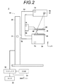
- FIG. 2 is a schematic configuration diagram of the radiation image processing apparatus 2 used in the present embodiment. As shown in FIG. 2, the radiographic image capturing apparatus 2 includes an imaging unit 50, a computer 32 connected to the imaging unit 50, a monitor 33 connected to the computer 32, and an input unit 34.
- the imaging unit 50 is capable of moving in a vertical direction (Z direction) with respect to the base 51, a rotatable rotating shaft 52, and an arm portion 53 coupled to the base 51 by the rotating shaft 52. It has. 3 shows the arm portion 53 viewed from the right direction in FIG.
- the arm portion 53 has an alphabet C shape, and a radiation stand 56 is attached to one end of the arm portion 53 so as to face the photography stand 54 at the other end.
- the rotation and vertical movement of the arm unit 53 are controlled by an arm controller 71 incorporated in the base 51.
- a radiation image detector 55 such as a flat panel detector and a detector controller 73 for controlling reading of a charge signal from the radiation image detector 55 are provided.
- a charge amplifier that converts the charge signal read from the radiation image detector 55 into a voltage signal
- a correlated double sampling circuit that samples the voltage signal output from the charge amplifier
- a voltage signal A circuit board or the like provided with an AD conversion unit or the like for converting the signal into a digital signal is also installed.
- the photographing table 54 is configured to be rotatable with respect to the arm unit 53, and even when the arm unit 53 is rotated with respect to the base 51, the direction of the photographing table 54 is fixed to the base 51. can do.
- the radiation image detector 55 can repeatedly perform recording and reading of a radiation image, and may use a so-called direct type radiation image detector that directly receives radiation and generates charges.
- a so-called indirect radiation image detector that converts radiation once into visible light and converts the visible light into a charge signal may be used.
- a radiation image signal readout method a radiation image signal is read out by turning on / off a TFT (thin film transistor) switch, or a radiation image is emitted by irradiating reading light. It is desirable to use a so-called optical readout system in which a signal is read out, but the present invention is not limited to this, and other systems may be used.
- a radiation source 57 and a radiation source controller 72 are housed inside the radiation irradiation unit 56.
- the radiation source controller 72 controls the timing of irradiating radiation from the radiation source 57 and the radiation generation conditions (tube current, time, tube current time product, etc.) in the radiation source 57.
- a compression plate 58 that is disposed above the imaging table 54 and presses and compresses the breast, a support portion 60 that supports the compression plate 58, and a support portion 60 in the vertical direction ( A moving mechanism 59 for moving in the Z direction) is provided.
- the position of the compression plate 58 and the compression pressure are controlled by the compression plate controller 74.
- the computer 32 includes a central processing unit (CPU), a storage device such as a semiconductor memory, a hard disk, and an SSD.
- the control unit 38a outputs predetermined control signals to the various controllers 71 to 74 to control the entire system.
- the radiation image storage unit 38b stores two two-dimensional radiation images (hereinafter, referred to as two-dimensional images) detected by the radiation image detector 55 by photographing from two different photographing directions.
- the display control unit 38c displays a three-dimensional image of the breast M on the monitor 33 after performing predetermined processing on the two two-dimensional images read from the radiation image storage unit 38b.
- the file generation unit 38d generates a three-dimensional image file including two two-dimensional images.
- the communication unit 38e transmits two two-dimensional images and three-dimensional images to the image server 4 via the network 6.
- the input unit 34 includes, for example, a pointing device such as a keyboard and a mouse, and accepts an input of shooting conditions including an enlargement ratio and an input of a shooting start instruction by a photographer.
- a pointing device such as a keyboard and a mouse
- the monitor 33 is configured to display a three-dimensional image in a three-dimensional manner using the two two-dimensional images output from the computer 32 when photographing a three-dimensional image.
- a configuration for stereoscopically viewing a three-dimensional image for example, two two-dimensional images are respectively displayed using two screens, and one of these radiographic images is observed by using a half mirror or a polarizing glass. It is possible to adopt a configuration in which a three-dimensional image is displayed by making it enter the right eye of the person and making the other radiation image enter the left eye of the observer.
- a configuration may be adopted in which a two-dimensional image is generated by superimposing two two-dimensional images shifted by a predetermined amount of parallax, and viewed stereoscopically by polarizing glass. Two two-dimensional images are changed to red and blue, respectively, and are shifted by a predetermined amount of parallax to generate a three-dimensional image, which is viewed stereoscopically by red and blue glasses equipped with a red filter and a blue filter. It is good also as composition to do. Moreover, it is good also as a structure stereoscopically displayed by displaying two two-dimensional images on the 3D display which can be stereoscopically viewed like a parallax barrier system and a lenticular system.
- photographing is performed as follows. First, the patient's breast M is placed on the imaging table 54, and the breast M is compressed with a predetermined pressure by the compression plate 58. Next, after various shooting conditions are input at the input unit 34, an instruction to start shooting is input.
- the control unit 38 a reads a convergence angle ⁇ for capturing a preset three-dimensional image, and outputs the read information about the convergence angle ⁇ to the arm controller 71.
- ⁇ 4 ° is stored in advance as information on the convergence angle ⁇ at this time.
- the present invention is not limited to this, and an arbitrary convergence angle is set in the input unit 34 by the photographer. Is possible.
- the arm controller 71 receives the information of the convergence angle ⁇ output from the control unit 38a, and the arm controller 71 first has the arm unit 53 in a direction perpendicular to the imaging table 54 as shown in FIG.
- the control signal is output as follows.
- the control unit 38 a notifies the radiation source controller 72 and the detector controller 73.
- a control signal is output so as to perform radiation irradiation and readout of a radiographic image signal.
- the position of the radiation source 57 in this state is a reference viewpoint position.
- radiation is emitted from the radiation source 57, a radiation image obtained by photographing the breast from the 0 ° direction is detected by the radiation image detector 55, and a radiation image signal is output from the radiation image detector 55 by the detector controller 73.
- the two-dimensional image acquired by photographing the breast from the 0 ° direction faces the breast from the vertical direction.
- the two-dimensional image acquired by photographing the breast from the 0 ° direction is referred to as a reference two-dimensional image G1.
- the arm controller 71 outputs a control signal so as to rotate the arm portion 53 by + ⁇ ° with respect to the direction perpendicular to the imaging table 54 as shown in FIG. That is, in the present embodiment, a control signal is output so that the arm unit 53 rotates 4 ° with respect to a direction perpendicular to the imaging table 54. Then, in a state where the arm unit 53 is rotated by 4 ° according to the control signal output from the arm controller 71, the control unit 38a subsequently applies radiation to the radiation source controller 72 and the detector controller 73 and the radiation. A control signal is output so as to read out the image signal.
- control unit 38a outputs a control signal to the radiation source controller 72 and the detector controller 73 so as to irradiate the radiation and read out the radiation image.
- this control signal radiation is emitted from the radiation source 57, a radiation image obtained by photographing the breast from a 4 ° direction is detected by the radiation image detector 55, and a radiation image signal is read by the detector controller 73, and a predetermined value is obtained. Is then stored as a two-dimensional image in the storage unit 38b of the computer 32.
- the two-dimensional image acquired by photographing the breast from the 4 ° direction does not face the breast from the vertical direction, in this embodiment, the two-dimensional image is obtained by photographing the breast from the 4 ° direction.
- the two-dimensional image is referred to as a reference two-dimensional image G2.
- the two two-dimensional images G1 and G2 stored in the radiation image storage unit 38b are read out, and a predetermined process is performed on the two-dimensional images G1 and G2 in the display control unit 38e.
- the three-dimensional image of the breast is displayed on the monitor 33.
- an image file F0 including two two-dimensional images G1 and G2 is generated by the file generation unit 38d, and the generated image file F0 is stored in the image server by the communication unit 38e. Sent to 4 and saved.
- the generated image file F0 includes two two-dimensional images G1 and G2 that can generate a three-dimensional image. Therefore, information indicating that the image file is an image file of an image that can be three-dimensionally displayed is described in the header of the image file F0.
- the image server 4 includes a recording medium 10 such as a hard disk for storing a plurality of image files, and a computer 12.
- a program for causing the computer 12 to function as the image distribution apparatus according to the present embodiment is installed in the computer 12.
- the image file transmitted from the radiation image capturing apparatus 2 is recorded on the recording medium 10.
- the computer 12 includes a central processing unit (CPU) and a storage device such as a semiconductor memory, a hard disk, and an SSD.
- a distribution control unit 12c (distribution control means) and a communication unit 12d are configured.
- the control unit 12a controls the computer 12 as a whole.
- the determination unit 12b transmits the terminal device 8 transmitted from the terminal device 8. Based on the information indicating the type of monitor, it is determined whether or not the monitor 8A of the terminal device 8 can be three-dimensionally displayed.
- the information indicating the type of the monitor 8A of the terminal device 8 includes information indicating whether or not the monitor 8A can perform three-dimensional display, and is transmitted to the image server 4 together with an image distribution request.
- the distribution control unit 12c distributes the image to the terminal device 8 based on the determination result of the determination unit 12b. That is, when the monitor 8A included in the terminal device 8 is a three-dimensional monitor capable of three-dimensional display, an image file capable of three-dimensional display is delivered to the terminal device 8 as it is. On the other hand, when the monitor 8A of the terminal device 8 is a two-dimensional monitor that cannot display three-dimensionally, the two-dimensional images G1 and G2 included in the image file are acquired at a position facing the subject breast from the vertical direction. The reference two-dimensional image G1 is distributed to the terminal device 8.
- the communication unit 12 d communicates with the terminal device 8 via the network 6.
- FIG. 6 is a flowchart showing processing performed in the present embodiment.
- the determination unit 12b includes three monitors 8A included in the terminal device 8 based on the information indicating the type of monitor transmitted from the terminal device 8. It is determined whether or not dimension display is possible (step ST2).
- the distribution control unit 12c searches the recording medium 10 for an image file for which a distribution request has been made, and searches for the image file in the terminal device 8. (3D image distribution, step ST3), and the process ends.
- the distribution control unit 12c searches the recording medium 10 for an image file for which a distribution request has been made, and stores the image file in the image file. Only the included reference two-dimensional image G1 is distributed to the terminal device 8 (step ST4), and the process ends.
- the monitor 8A of the terminal device 8 can display three-dimensionally, a three-dimensional image is generated from the two two-dimensional images G1 and G2 in the terminal device 8, and the generated three-dimensional image is converted into a three-dimensional image. It is displayed on the monitor 8A so as to be visible.
- an arbitrary method such as a method using a half mirror or a polarizing glass, an anaglyph method, a parallax barrier method, or a lenticular method as described above may be used. it can.
- the monitor 8A of the terminal device 8 when there is an image distribution instruction from the terminal device 8, it is determined whether or not the monitor 8A of the terminal device 8 can display three-dimensionally.
- the reference two-dimensional image G1 that faces the breast from the vertical direction among the two-dimensional images G1 and G2 is distributed to the terminal device 8.
- a 3D image is generated from a 2D image and displayed in 3D.
- 3D display is performed by an anaglyph method or the like, two 2D images are superimposed.
- a three-dimensional image can be generated.
- a three-dimensional image can be generated in advance when three-dimensional display is performed by the parallax barrier method and the lenticular method.
- the radiographic imaging device 2 may generate a three-dimensional image, include the two two-dimensional images G1, G2 and the three-dimensional image in the image file, and transmit them to the image server 4 for storage. .
- the monitor 8A of the terminal device 8 that has requested the image distribution is capable of three-dimensional display, the three-dimensional image included in the image file is distributed to the terminal device 8.
- a two-dimensional image obtained by photographing the breast from the 0 degree direction is distributed as a reference two-dimensional image.
- the breast is set to 0.
- an image taken from a direction different from the angle is used as a reference.
- a two-dimensional image acquired by photographing from a reference direction may be distributed as a reference two-dimensional image.
- the radiographic image capturing apparatus of the present invention is a mammographic image capturing apparatus.
- the subject is not limited to the breast, and for example, a radiographic image capturing apparatus that captures the chest, head, or the like may be used. Is possible.
Landscapes
- Health & Medical Sciences (AREA)
- Life Sciences & Earth Sciences (AREA)
- Engineering & Computer Science (AREA)
- Medical Informatics (AREA)
- Physics & Mathematics (AREA)
- Heart & Thoracic Surgery (AREA)
- Surgery (AREA)
- High Energy & Nuclear Physics (AREA)
- Veterinary Medicine (AREA)
- Nuclear Medicine, Radiotherapy & Molecular Imaging (AREA)
- Optics & Photonics (AREA)
- Pathology (AREA)
- Radiology & Medical Imaging (AREA)
- Biomedical Technology (AREA)
- Public Health (AREA)
- Molecular Biology (AREA)
- Biophysics (AREA)
- Animal Behavior & Ethology (AREA)
- General Health & Medical Sciences (AREA)
- Dentistry (AREA)
- Oral & Maxillofacial Surgery (AREA)
- Multimedia (AREA)
- Signal Processing (AREA)
- Mathematical Physics (AREA)
- Apparatus For Radiation Diagnosis (AREA)
- Processing Or Creating Images (AREA)
- Information Transfer Between Computers (AREA)
- Testing, Inspecting, Measuring Of Stereoscopic Televisions And Televisions (AREA)
Abstract
装置が大型化及び高コスト化することなく、3次元画像および2次元画像を選択的に端末装置に配信するに際し、適切な画像を配信できるようにする。端末装置8からの画像配信要求を受信すると、コンピュータ12は端末装置8から送信されたモニタ8Aの種類を表す情報に基づいて、端末装置8が有するモニタ8Aが3次元表示可能であるか否かを判定する。モニタ8Aが3次元表示可能である場合、3次元表示可能な画像の画像ファイルを端末装置8に配信する。モニタ8Aが3次元表示不可能である場合、3次元表示可能な画像の画像ファイルに含まれる、被検体を垂直方向から臨む位置において取得した、基準となる2次元画像G1を端末装置8に配信する。
Description
本発明は、立体視可能な医用3次元画像を、画像の配信要求を行った端末装置に配信するための画像配信装置および方法に関するものである。
従来、複数の画像を組み合わせて表示することにより、視差を利用して立体視できることが知られている。このような立体視できる画像(以下、立体視画像または3次元画像という)は、同一の被写体を異なる方向から撮影して取得された互いに視差のある複数の画像に基づいて表示される。
そして、このような3次元画像の表示は、デジタルカメラやテレビ等の分野だけでなく、放射線画像撮影の分野においても利用されている。すなわち、被検体に対して、被検体を垂直方向から臨む基準位置およびこの基準位置から所定角度ずれた参照位置から放射線を照射し、その被検体を透過した放射線を放射線画像検出器によりそれぞれ検出して互いに視差のある複数の放射線画像を取得し、これらの放射線画像に基づいて3次元画像を表示することが行われている。このように3次元画像を表示することによって奥行感のある放射線画像を観察することができるため、診断をより行いやすくすることができる。
ところで、立体視は、上述した複数の放射線画像または複数の放射線画像から生成した3次元画像を、立体視を行うための3次元モニタに3次元表示することにより行われる。しかしながら、2次元表示のみしか行うことができないモニタ(2次元モニタとする)には、3次元画像を立体視可能に表示することができない。また、2次元モニタに3次元画像を表示すると、像が2重に見える等して、画像が非常に観察しにくいものとなる。この場合、2次元モニタには、立体視できない画像、すなわち2次元画像(例えば3次元画像を生成するために使用した放射線画像)を3次元画像に代えて表示するようにすればよい。
このため、画像ファイルが3次元画像を含むか否かを画像ファイルのヘッダに記述しておき、3次元画像を含むものである場合には3次元画像を用いて3次元表示を行い、3次元画像を含むものでない場合には、画像ファイルは2次元画像のみを含むことから、2次元画像を表示する手法が提案されている(特許文献1参照)。また、ファイルの識別情報に基づいて、画像の表示モードを2次元表示モードまたは3次元表示モードに切り替える手法も提案されている(特許文献2参照)。また、特許文献2には、サーバに画像を保存しておき、2次元表示しかできない端末装置から画像配信の要求があった場合において、その画像が3次元画像である場合には、端末装置に3次元画像を配信しないようにする手法も提案されている。さらに、特許文献3には、表示能力の認識結果と表示する画像の認識結果に基づき、2次元画像を3次元変換し、好適な3次元画像を取得する手法が提案されている。
しかしながら、上記特許文献1に記載された手法は、画像ファイルが3次元画像を含むものである場合に3次元表示を行うものであり、3次元表示を行う画像ファイルには3次元画像が含まれるのみである。また、特許文献2に記載された手法も、サーバに2次元画像および3次元画像が保存されている場合において、要求があった画像の種類に応じて2次元モードおよび3次元モードに表示モードを切り換えるものであるため、3次元表示を行うための画像ファイルには3次元画像が含まれるのみである。このため、3次元画像について2次元表示を行いたい場合には、3次元画像とは別に3次元画像に含まれる被写体の2次元画像を取得し、3次元画像とともに2次元画像を保存しておく必要がある。
しかしながら、3次元画像および2次元画像の双方を保存するためには、2次元画像を撮影する作業が必要であり、さらに画像の保存容量も増大する。このため、3次元画像を生成するために使用した2次元画像を、2次元表示のために使用することが考えられる。ここで、放射線画像の3次元画像を生成する場合、互いに異なる方向から被検体に放射線を照射することにより得られる2次元画像が用いられるが、2次元画像を用いた診断を精度良く行うためには、被検体を正面から観察することができる画像を用いることが好ましい。また、特許文献3に記載された手法は、2次元表示しかできない表示装置に3次元画像を表示しようとする場合に、3次元画像生成装置を用いて、新たに擬似3次元画像を生成し、表示するものである。しかしながら、特許文献3に記載の装置は、3次元画像生成装置を備えていることに起因して装置構成が複雑であることから、装置が大型化および高コスト化するという問題を有する。
本発明は上記事情に鑑みなされたものであり、装置が大型化及び高コスト化することなく、3次元画像および2次元画像を選択的に端末装置に配信するに際し、適切な画像を配信できるようにすることを目的とする。
本発明による画像配信装置は、3次元画像を生成可能な複数の2次元画像を含む画像ファイル、または複数の2次元画像および3次元画像を含む画像ファイルを保存する保存手段と、端末装置と通信を行う通信手段と、端末装置からの画像配信の指示があった場合、端末装置が3次元表示可能であるか否かの判定を行う判定手段と、端末装置が3次元表示不可能であると判定された場合、複数の2次元画像のうち、複数の視点のうちの基準となる視点において取得した2次元画像を端末装置に配信する配信制御手段とを備えたことを特徴とする。
なお、本発明による画像配信装置においては、前記基準となる視点は、垂直方向から被検体を垂直方向から臨む視点としてもよい。
また、本発明による画像配信装置においては、前記判定手段は、端末装置から送信された端末装置の表示手段の種別を表す情報に基づいて判定を行う手段としてもよい。
また、本発明による画像配信装置においては、配信制御手段は、端末装置が3次元表示可能であると判定された場合に複数の2次元画像または3次元画像を端末装置に配信する手段としてもよい。
また、本発明による画像配信装置においては、端末装置は複数の2次元画像または3次元画像をアナグリフ方式にて3次元表示するものとしてもよい。
本発明による画像配信装置の制御方法は、3次元画像を生成可能な複数の2次元画像を含む画像ファイル、または複数の2次元画像および3次元画像を含む画像ファイルを保存する保存手段と、端末装置と通信を行う通信手段とを備えた画像配信装置の制御方法であって、端末装置からの画像配信の指示があった場合に端末装置が3次元表示可能であるか否かの判定を行い、端末装置が3次元表示不可能であると判定された場合、複数の2次元画像のうち、複数の視点のうちの基準となる視点において取得した2次元画像を端末装置に配信することを特徴とする。
本発明によれば、端末装置からの画像配信の指示があった場合、端末装置が3次元表示可能であるか否かの判定を行い、端末装置が3次元表示不可能であると判定された場合、複数の2次元画像のうち基準となる視点において取得した2次元画像を端末装置に配信するようにしたものである。このため、端末装置においては、基準となる視点位置から被検体を観察できる2次元画像が表示されるため、表示された2次元画像を用いての診断を精度良く行うことができる。
とくに、複数の2次元画像のうち被検体を垂直方向から臨む2次元画像を端末装置に配信することにより、端末装置においては、被検体を正面から観察できる2次元画像が表示されるため、表示された2次元画像を用いての診断をより精度良く行うことができる。また、本願発明の画像配信装置は、装置構成が単純であることから、装置が大型化及び高コスト化することがない。
以下、図面を参照して本発明の実施形態について説明する。図1は本発明の実施形態による画像配信装置を用いた医用画像配信システムの構成を示す概略ブロック図である。図1に示すように、本実施形態による医用画像配信システム1は、放射線画像撮影装置2、画像サーバ4、ネットワーク6および複数の端末装置8を備える。そして、放射線画像撮影装置2において取得した医用画像を画像サーバ4に保存し、端末装置8からの画像配信要求に応じて、画像サーバ4に保存された医用画像をネットワーク6を介して要求を行った端末装置8に配信し、端末装置8のモニタ8Aに医用画像を表示するよう構成されている。
放射線画像撮影装置2は、例えば乳房の放射線画像を3次元表示するために、異なる視点位置における2つの2次元の医用画像(以下2次元画像とする)を取得するものである。図2は本実施形態において使用される放射線画像処理装置2の概略構成図である。図2に示すように放射線画像撮影装置2は、撮影部50と、撮影部50に接続されたコンピュータ32と、コンピュータ32に接続されたモニタ33と、入力部34とを備えている。
撮影部50は、基台51と、基台51に対し上下方向(Z方向)に移動可能であり、かつ回転可能な回転軸52と、回転軸52により基台51と連結されたアーム部53を備えている。なお、図3には図2の右方向から見たアーム部53を示している。
アーム部53はアルファベットのCの形をしており、その一端には撮影台54が、その他端には撮影台54と対向するように放射線照射部56が取り付けられている。アーム部53の回転および上下方向の移動は、基台51に組み込まれたアームコントローラ71により制御される。
撮影台54の内部には、フラットパネルディテクタ等の放射線画像検出器55と、放射線画像検出器55からの電荷信号の読み出しを制御する検出器コントローラ73とが備えられている。
また、撮影台54の内部には、放射線画像検出器55から読み出された電荷信号を電圧信号に変換するチャージアンプ、チャージアンプから出力された電圧信号をサンプリングする相関2重サンプリング回路、電圧信号をデジタル信号に変換するAD変換部等が設けられた回路基板等も設置されている。
また、撮影台54はアーム部53に対し回転可能に構成されており、基台51に対してアーム部53が回転したときでも、撮影台54の向きは基台51に対し固定された向きとすることができる。
放射線画像検出器55は、放射線画像の記録と読み出しとを繰り返して行うことができるものであり、放射線の照射を直接受けて電荷を発生する、いわゆる直接型の放射線画像検出器を用いてもよいし、放射線を一旦可視光に変換し、その可視光を電荷信号に変換する、いわゆる間接型の放射線画像検出器を用いるようにしてもよい。また、放射線画像信号の読出方式としては、TFT(thin film transistor)スイッチがオン・オフされることによって放射線画像信号が読み出される、いわゆるTFT読出方式のものや、読取光を照射することによって放射線画像信号が読み出される、いわゆる光読出方式のものを用いることが望ましいが、これに限らずその他のものを用いるようにしてもよい。
放射線照射部56の内部には、放射線源57と、放射線源コントローラ72とが収納されている。放射線源コントローラ72は、放射線源57から放射線を照射するタイミングと、放射線源57における放射線発生条件(管電流、時間、管電流時間積等)とを制御するものである。
また、アーム部53の中央部には、撮影台54の上方に配置されて乳房を押さえつけて圧迫する圧迫板58と、その圧迫板58を支持する支持部60と、支持部60を上下方向(Z方向)に移動させる移動機構59とが設けられている。圧迫板58の位置および圧迫圧は、圧迫板コントローラ74により制御される。
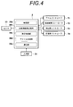
コンピュータ32は、中央処理装置(CPU)および半導体メモリやハードディスクやSSD等のストレージデバイス等を備えており、これらのハードウェアによって、図4に示すような制御部38a、放射線画像記憶部38b(保存手段)、表示制御部38cおよび通信部38e(通信手段)が構成されている。
制御部38aは、各種のコントローラ71~74に対して所定の制御信号を出力し、システム全体の制御を行うものである。
放射線画像記憶部38bは、互いに異なる2つの撮影方向からの撮影によって放射線画像検出器55によって検出された2つの2次元の放射線画像(以下、2次元画像とする)を記憶するものである。
表示制御部38cは、放射線画像記憶部38bから読み出された2つの2次元画像に対して所定の処理を施した後、モニタ33に乳房Mの3次元画像を表示させるものである。
ファイル生成部38dは、2つの2次元画像を含む、3次元画像の画像ファイルを生成するものである。
通信部38eは、2枚の2次元画像および3次元画像をネットワーク6を介して画像サーバ4に送信するものである。
入力部34は、例えば、キーボードやマウス等のポインティングデバイスから構成されるものであり、撮影者による拡大率を含む撮影条件等の入力や撮影開始指示の入力等を受け付けるものである。
モニタ33は、3次元画像の撮影時においては、コンピュータ32から出力された2つの2次元画像を用いて3次元画像を3次元表示して立体視可能なように構成されたものである。3次元画像を立体視するための構成としては、例えば、2つの画面を用いて2つの2次元画像をそれぞれ表示させて、これらをハーフミラーや偏光グラス等を用いることで一方の放射線画像は観察者の右目に入射させ、他方の放射線画像は観察者の左目に入射させることによって3次元画像を表示する構成を採用することができる。また、2つの2次元画像を所定の視差量だけずらして重ね合わせた3次元画像を生成し、これを偏光グラスで観察することにより立体視する構成としてもよいし、アナグリフ方式のように、2つの2次元画像を赤色および青色にそれぞれ変更し、所定の視差量だけずらして重ね合わせて3次元画像を生成し、これを赤フィルタおよび青フィルタを備えた赤青メガネで観察することにより立体視する構成としてもよい。また、パララックスバリア方式およびレンチキュラー方式のように、2つの2次元画像を立体視可能な3D表示器に表示することにより立体視する構成としてもよい。
このような放射線画像撮影装置2においては、以下のようにして撮影が行われる。まず、撮影台54の上に患者の乳房Mが設置され、圧迫板58により乳房Mが所定の圧力によって圧迫される。次に、入力部34おいて、種々の撮影条件が入力された後、撮影開始の指示が入力される。
そして、入力部34において撮影開始の指示があると、乳房Mの3次元画像を構成する2つの2次元画像のうちの1つの2次元画像の撮影が行われる。具体的には、まず、制御部38aが、予め設定された3次元画像の撮影のための輻輳角θを読み出し、その読み出した輻輳角θの情報をアームコントローラ71に出力する。なお、本実施形態においては、このときの輻輳角θの情報としてθ=4°が予め記憶されているものとするが、これに限らず、撮影者によって入力部34において任意の輻輳角を設定可能である。
そして、アームコントローラ71において、制御部38aから出力された輻輳角θの情報が受け付けられ、アームコントローラ71は、まず、図3に示すように、アーム部53が撮影台54に垂直な方向となるように制御信号を出力する。
そして、このアームコントローラ71から出力された制御信号に応じてアーム部53が、撮影台54に対して垂直な方向となった状態において、制御部38aは、放射線源コントローラ72および検出器コントローラ73に対して放射線の照射と放射線画像信号の読み出しを行うよう制御信号を出力する。なお、この状態における放射線源57の位置が、基準となる視点位置となる。この制御信号に応じて、放射線源57から放射線が射出され、乳房を0°方向から撮影した放射線画像が放射線画像検出器55によって検出され、検出器コントローラ73によって放射線画像検出器55から放射線画像信号が読み出され、その放射線画像信号に対して所定の信号処理が施された後、コンピュータ32の放射線画像記憶部38bに2次元画像として記憶される。
なお、乳房を0°方向から撮影することにより取得した2次元画像は、乳房を垂直な方向から臨むものとなる。本実施形態においては、乳房を0°方向から撮影することにより取得した2次元画像を、基準2次元画像G1と称する。
次に、アームコントローラ71は、図2に示すように、アーム部53を撮影台54に垂直な方向に対して+θ°回転するよう制御信号を出力する。すなわち、本実施形態においては、アーム部53を撮影台54に垂直な方向に対して4°回転するよう制御信号を出力する。そして、このアームコントローラ71から出力された制御信号に応じてアーム部53が4°回転した状態において、続いて制御部38aは、放射線源コントローラ72および検出器コントローラ73に対して放射線の照射と放射線画像信号の読み出しを行うよう制御信号を出力する。
具体的には、制御部38aが、放射線源コントローラ72および検出器コントローラ73に対して放射線の照射と放射線画像の読み出しを行うよう制御信号を出力する。この制御信号に応じて、放射線源57から放射線が射出され、乳房を4°方向から撮影した放射線画像が放射線画像検出器55によって検出され、検出器コントローラ73によって放射線画像信号が読み出され、所定の信号処理が施された後、コンピュータ32の記憶部38bに2次元画像として記憶される。
なお、乳房を4°方向から撮影することにより取得した2次元画像は、乳房を垂直な方向から臨むものとはならないため、本実施形態においては、乳房を4°方向から撮影することにより取得した2次元画像を、参照2次元画像G2と称する。
そして、放射線画像記憶部38bに記憶された2つの2次元画像G1,G2が読み出され、表示制御部38eにおいてこれらの2次元画像G1,G2に対して所定の処理が施された後、モニタ33に出力され、モニタ33において、乳房の3次元画像が表示される。
さらに、放射線画像撮影装置2の撮影者による確認後、ファイル生成部38dにより2つの2次元画像G1,G2を含む画像ファイルF0が生成され、生成された画像ファイルF0が、通信部38eにより画像サーバ4に送信されて保存される。ここで、生成された画像ファイルF0は、3次元画像を生成可能な2つの2次元画像G1,G2を含むものとなっている。このため、画像ファイルF0のヘッダには、その画像ファイルが3次元表示可能な画像の画像ファイルであることを示す情報が記述される。
図1に戻り、画像サーバ4は、複数の画像ファイルを保存するハードディスク等の記録媒体10と、コンピュータ12とを備える。コンピュータ12には、コンピュータ12を本実施形態による画像配信装置として機能させるためのプログラムがインストールされている。なお、放射線画像撮影装置2から送信された画像ファイルは、記録媒体10に記録される。
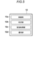
コンピュータ12は、中央処理装置(CPU)および半導体メモリやハードディスクやSSD等のストレージデバイス等を備えており、これらのハードウェアによって、図5に示すような制御部12a、判定部12b(判定手段)、配信制御部12c(配信制御手段)および通信部12dを構成されている。
制御部12aは、コンピュータ12全体の制御を行うものである。
判定部12bは、後述するように複数の端末装置8のうちのいずれかの端末装置8から、ネットワーク6経由で画像の配信要求があった場合、端末装置8から送信された、端末装置8のモニタの種類を表す情報に基づいて、端末装置8が有するモニタ8Aが3次元表示可能であるか否かを判定する。なお、端末装置8のモニタ8Aの種類を表す情報は、モニタ8Aが3次元表示可能であるか否かを表す情報を含むものであり、画像の配信要求とともに画像サーバ4に送信される。
配信制御部12cは、判定部12bの判定結果に基づいて、端末装置8に画像を配信する。すなわち、端末装置8が有するモニタ8Aが3次元表示可能な3次元モニタである場合には、3次元表示可能な画像ファイルをそのまま端末装置8に配信する。一方、端末装置8が有するモニタ8Aが3次元表示不可能な2次元モニタである場合、画像ファイルに含まれる2次元画像G1,G2のうち、被検体である乳房を垂直方向から臨む位置において取得した基準2次元画像G1を端末装置8に配信する。
通信部12dは、ネットワーク6を介して端末装置8と通信を行う。
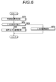
次いで、本実施形態において行われる処理について説明する。図6は本実施形態において行われる処理を示すフローチャートである。端末装置8からの画像配信要求を通信部12dが受信すると(ステップST1)、端末装置8から送信されたモニタの種類を表す情報に基づいて、判定部12bが端末装置8が有するモニタ8Aが3次元表示可能であるか否かを判定する(ステップST2)。
端末装置8が有するモニタ8Aが3次元表示可能である場合(ステップST2肯定)、配信制御部12cは配信要求があった画像の画像ファイルを記録媒体10から検索し、その画像ファイルを端末装置8に配信し(3次元画像配信、ステップST3)、処理を終了する。
一方、端末装置8が有するモニタ8Aが3次元表示不可能である場合(ステップST2否定)、配信制御部12cは配信要求があった画像の画像ファイルを記録媒体10から検索し、その画像ファイルに含まれる、基準2次元画像G1のみを端末装置8に配信し(ステップST4)、処理を終了する。
これにより、端末装置8のモニタ8Aが3次元表示可能なものである場合には、端末装置8において2つの2次元画像G1,G2から3次元画像が生成され、生成された3次元画像が立体視可能にモニタ8Aに表示される。この場合、モニタ8Aにおいて3次元画像を3次元表示する構成としては、上述したようなハーフミラーや偏光グラスを用いる方式、アナグリフ方式、パララックスバリア方式およびレンチキュラー方式等の任意の方式を用いることができる。
一方、端末装置8のモニタ8Aが3次元表示不可能なものである場合には、乳房を垂直方向から臨む位置において取得された2次元画像G1がモニタ8Aに表示される。
このように、本実施形態においては、端末装置8からの画像配信の指示があった場合、端末装置8のモニタ8Aが3次元表示可能であるか否かの判定を行い、端末装置8のモニタ8Aが3次元表示不可能であると判定された場合、2次元画像G1,G2のうち乳房を垂直方向から臨む基準2次元画像G1を端末装置8に配信するようにしたものである。これにより、端末装置8においては、被検体を正面から観察できる2次元画像が表示されるため、表示された2次元画像を用いての診断を精度良く行うことができる。
なお、上記実施形態においては、2次元画像から3次元画像を生成して3次元表示を行うようにしているが、アナグリフ方式等により3次元表示を行う場合、2つの2次元画像を重ね合わせることにより3次元画像を生成することができる。また、パララックスバリア方式およびレンチキュラー方式により3次元表示を行う場合にも、予め3次元画像を生成することができる。このため、放射線画像撮影装置2において、3次元画像を生成し、画像ファイルに2つの2次元画像G1,G2および3次元画像を含めて、画像サーバ4に送信して保存するようにしてもよい。この場合、画像配信要求を行った端末装置8のモニタ8Aが3次元表示可能なものである場合、画像ファイルに含まれる3次元画像が端末装置8に配信されることとなる。
また、上記実施形態においては、乳房を0度方向から撮影して取得した2次元画像を基準2次元画像として配信しているが、2つの2次元画像を取得するための撮影時に、乳房を0度とは異なる方向から撮影した画像を基準とする場合がある。この場合、2つの2次元画像のうち、基準となる方向から撮影を行うことにより取得した2次元画像を基準2次元画像として配信するようにすればよい。
また、上記実施形態においては、本発明の放射線画像撮影装置を乳房画像撮影装置としているが、被検体としては乳房に限らず、例えば胸部や頭部等を撮影する放射線画像撮影装置を用いることも可能である。
1 医用画像配信システム
2 放射線画像撮影装置
4 画像サーバ
6 ネットワーク
8 端末装置
10 記録媒体
12 コンピュータ
12a 制御部
12b 判定部
12c 配信制御部
12d 通信部
2 放射線画像撮影装置
4 画像サーバ
6 ネットワーク
8 端末装置
10 記録媒体
12 コンピュータ
12a 制御部
12b 判定部
12c 配信制御部
12d 通信部
Claims (5)
- 3次元画像を生成可能な複数の視点から取得した複数の2次元画像を含む画像ファイル、または該複数の2次元画像および前記3次元画像を含む画像ファイルを保存する保存手段と、
端末装置と通信を行う通信手段と、
前記端末装置からの画像配信の指示があった場合に該端末装置が3次元表示可能であるか否かの判定を行う判定手段と、
前記端末装置が3次元表示不可能であると判定された場合に前記複数の2次元画像のうち、前記複数の視点のうちの基準となる視点において取得した2次元画像を前記端末装置に配信する配信制御手段とを備えたことを特徴とする画像配信装置。 - 前記基準となる視点は、垂直方向から被検体を臨む視点であることを特徴とする請求項1記載の画像配信装置。
- 前記判定手段は、前記端末装置から送信された該端末装置の表示手段の種別を表す情報に基づいて前記判定を行うことを特徴とする請求項1または2記載の画像配信装置。
- 前記配信制御手段は、前記端末装置が3次元表示可能であると判定された場合、前記複数の2次元画像または前記3次元画像を前記端末装置に配信することを特徴とする請求項1から3のいずれか1項記載の画像配信装置。
- 3次元画像を生成可能な複数の視点から取得した複数の2次元画像を含む画像ファイル、または該複数の2次元画像および前記3次元画像を含む画像ファイルを保存する保存手段と、
端末装置と通信を行う通信手段とを備えた画像配信装置の制御方法であって、
前記端末装置からの画像配信の指示があった場合、該端末装置が3次元表示可能であるか否かの判定を行い、
前記端末装置が3次元表示不可能であると判定された場合、前記複数の2次元画像のうち、前記複数の視点のうちの基準となる視点において取得した2次元画像を前記端末装置に配信することを特徴とする画像配信装置の制御方法。
Applications Claiming Priority (4)
| Application Number | Priority Date | Filing Date | Title |
|---|---|---|---|
| JP2010191976 | 2010-08-30 | ||
| JP2010-191976 | 2010-08-30 | ||
| JP2011-025779 | 2011-02-09 | ||
| JP2011025779A JP2012073996A (ja) | 2010-08-30 | 2011-02-09 | 画像配信装置および方法 |
Publications (1)
| Publication Number | Publication Date |
|---|---|
| WO2012029705A1 true WO2012029705A1 (ja) | 2012-03-08 |
Family
ID=45772792
Family Applications (1)
| Application Number | Title | Priority Date | Filing Date |
|---|---|---|---|
| PCT/JP2011/069426 Ceased WO2012029705A1 (ja) | 2010-08-30 | 2011-08-29 | 画像配信装置および方法 |
Country Status (2)
| Country | Link |
|---|---|
| JP (1) | JP2012073996A (ja) |
| WO (1) | WO2012029705A1 (ja) |
Families Citing this family (1)
| Publication number | Priority date | Publication date | Assignee | Title |
|---|---|---|---|---|
| HK1222064A1 (zh) * | 2013-09-10 | 2017-06-16 | 卡尔加里科学股份有限公司 | 用於分布式服务器侧和客户机侧图像数据绘制的架构 |
Citations (4)
| Publication number | Priority date | Publication date | Assignee | Title |
|---|---|---|---|---|
| JPH09218268A (ja) * | 1996-02-08 | 1997-08-19 | Daiichi Rajio Isotope Kenkyusho:Kk | ガンマーカメラの簡易三次元画像を得る方法 |
| JP2006135747A (ja) * | 2004-11-08 | 2006-05-25 | Canon Inc | 三次元画像変換装置ならびに制御方法 |
| JP2006180366A (ja) * | 2004-12-24 | 2006-07-06 | Fuji Photo Film Co Ltd | 立体視画像生成装置および方法並びにプログラム |
| JP2010034704A (ja) * | 2008-07-25 | 2010-02-12 | Sony Corp | 再生装置及び再生方法 |
-
2011
- 2011-02-09 JP JP2011025779A patent/JP2012073996A/ja not_active Withdrawn
- 2011-08-29 WO PCT/JP2011/069426 patent/WO2012029705A1/ja not_active Ceased
Patent Citations (4)
| Publication number | Priority date | Publication date | Assignee | Title |
|---|---|---|---|---|
| JPH09218268A (ja) * | 1996-02-08 | 1997-08-19 | Daiichi Rajio Isotope Kenkyusho:Kk | ガンマーカメラの簡易三次元画像を得る方法 |
| JP2006135747A (ja) * | 2004-11-08 | 2006-05-25 | Canon Inc | 三次元画像変換装置ならびに制御方法 |
| JP2006180366A (ja) * | 2004-12-24 | 2006-07-06 | Fuji Photo Film Co Ltd | 立体視画像生成装置および方法並びにプログラム |
| JP2010034704A (ja) * | 2008-07-25 | 2010-02-12 | Sony Corp | 再生装置及び再生方法 |
Also Published As
| Publication number | Publication date |
|---|---|
| JP2012073996A (ja) | 2012-04-12 |
Similar Documents
| Publication | Publication Date | Title |
|---|---|---|
| JPWO2012108187A1 (ja) | 立体視用画像生成装置および方法、並びにプログラム | |
| WO2012081244A1 (ja) | 表示装置 | |
| JP2012066049A (ja) | 放射線画像撮影装置および立体視画像表示方法 | |
| JP2012029759A (ja) | 放射線画像撮影表示方法および装置 | |
| JP2012061188A (ja) | 放射線画像撮影装置および方法 | |
| JP2012165358A (ja) | 立体視画像表示装置 | |
| US8963917B2 (en) | Radiological breast image display method, radiological breast image display apparatus, and program | |
| WO2012029705A1 (ja) | 画像配信装置および方法 | |
| JP5695524B2 (ja) | 立体視画像表示装置および方法並びにプログラム | |
| JP5946070B2 (ja) | 画像再生システムおよび画像ファイル生成装置 | |
| JP2012024516A (ja) | 放射線画像撮影表示方法および装置 | |
| WO2012056695A1 (ja) | 立体視画像表示装置および方法並びにプログラム | |
| WO2012063419A1 (ja) | 立体視画像表示装置および方法並びにプログラム | |
| JP2012068610A (ja) | 立体視画像表示装置、放射線画像撮影表示システムおよび立体視画像表示方法 | |
| WO2012056679A1 (ja) | 立体視画像表示システムおよび立体視画像用表示装置 | |
| WO2012105188A1 (ja) | 立体視画像表示装置および方法並びにプログラム | |
| JP2012170044A (ja) | 立体視画像表示装置 | |
| JP2012105047A (ja) | 立体視画像表示装置および方法並びにプログラム | |
| JP2012178626A (ja) | 立体視放射線画像表示方法および装置 | |
| WO2012056677A1 (ja) | 立体視画像表示装置 | |
| JP2013154165A (ja) | 画像再生装置および画像再生方法並びにプログラム | |
| WO2013024572A1 (ja) | 画像再生装置および画像再生方法並びにプログラム | |
| JP2013123553A (ja) | 放射線画像撮影装置 | |
| WO2012039126A1 (ja) | 放射線画像撮影装置、画像データ圧縮装置および画像データ圧縮方法 | |
| JP2012176002A (ja) | 放射線画像撮影装置および放射線画像撮影方法 |
Legal Events
| Date | Code | Title | Description |
|---|---|---|---|
| 121 | Ep: the epo has been informed by wipo that ep was designated in this application |
Ref document number: 11821721 Country of ref document: EP Kind code of ref document: A1 |
|
| NENP | Non-entry into the national phase |
Ref country code: DE |
|
| 122 | Ep: pct application non-entry in european phase |
Ref document number: 11821721 Country of ref document: EP Kind code of ref document: A1 |