WO2012026573A1 - 電力管理装置 - Google Patents
電力管理装置 Download PDFInfo
- Publication number
- WO2012026573A1 WO2012026573A1 PCT/JP2011/069269 JP2011069269W WO2012026573A1 WO 2012026573 A1 WO2012026573 A1 WO 2012026573A1 JP 2011069269 W JP2011069269 W JP 2011069269W WO 2012026573 A1 WO2012026573 A1 WO 2012026573A1
- Authority
- WO
- WIPO (PCT)
- Prior art keywords
- power
- charge
- load
- storage device
- power management
- Prior art date
- Legal status (The legal status is an assumption and is not a legal conclusion. Google has not performed a legal analysis and makes no representation as to the accuracy of the status listed.)
- Ceased
Links
Images


Classifications
-
- H—ELECTRICITY
- H02—GENERATION; CONVERSION OR DISTRIBUTION OF ELECTRIC POWER
- H02J—ELECTRIC POWER NETWORKS; CIRCUIT ARRANGEMENTS OR SYSTEMS FOR SUPPLYING OR DISTRIBUTING ELECTRIC POWER; SYSTEMS FOR STORING ELECTRIC ENERGY
- H02J7/00—Circuit arrangements for charging or discharging batteries or for supplying loads from batteries
- H02J7/34—Parallel operation in networks using both storage and other DC sources, e.g. providing buffering
-
- H—ELECTRICITY
- H01—ELECTRIC ELEMENTS
- H01M—PROCESSES OR MEANS, e.g. BATTERIES, FOR THE DIRECT CONVERSION OF CHEMICAL ENERGY INTO ELECTRICAL ENERGY
- H01M10/00—Secondary cells; Manufacture thereof
- H01M10/42—Methods or arrangements for servicing or maintenance of secondary cells or secondary half-cells
- H01M10/425—Structural combination with electronic components, e.g. electronic circuits integrated to the outside of the casing
-
- H—ELECTRICITY
- H01—ELECTRIC ELEMENTS
- H01M—PROCESSES OR MEANS, e.g. BATTERIES, FOR THE DIRECT CONVERSION OF CHEMICAL ENERGY INTO ELECTRICAL ENERGY
- H01M10/00—Secondary cells; Manufacture thereof
- H01M10/42—Methods or arrangements for servicing or maintenance of secondary cells or secondary half-cells
- H01M10/44—Methods for charging or discharging
-
- H—ELECTRICITY
- H01—ELECTRIC ELEMENTS
- H01M—PROCESSES OR MEANS, e.g. BATTERIES, FOR THE DIRECT CONVERSION OF CHEMICAL ENERGY INTO ELECTRICAL ENERGY
- H01M10/00—Secondary cells; Manufacture thereof
- H01M10/42—Methods or arrangements for servicing or maintenance of secondary cells or secondary half-cells
- H01M10/48—Accumulators combined with arrangements for measuring, testing or indicating the condition of cells, e.g. the level or density of the electrolyte
-
- H—ELECTRICITY
- H02—GENERATION; CONVERSION OR DISTRIBUTION OF ELECTRIC POWER
- H02J—ELECTRIC POWER NETWORKS; CIRCUIT ARRANGEMENTS OR SYSTEMS FOR SUPPLYING OR DISTRIBUTING ELECTRIC POWER; SYSTEMS FOR STORING ELECTRIC ENERGY
- H02J3/00—Circuit arrangements for AC mains or AC distribution networks
- H02J3/28—Arrangements for balancing of the load in networks by storage of energy
- H02J3/32—Arrangements for balancing of the load in networks by storage of energy using batteries or super capacitors with converting means
-
- H—ELECTRICITY
- H02—GENERATION; CONVERSION OR DISTRIBUTION OF ELECTRIC POWER
- H02J—ELECTRIC POWER NETWORKS; CIRCUIT ARRANGEMENTS OR SYSTEMS FOR SUPPLYING OR DISTRIBUTING ELECTRIC POWER; SYSTEMS FOR STORING ELECTRIC ENERGY
- H02J3/00—Circuit arrangements for AC mains or AC distribution networks
- H02J3/38—Arrangements for feeding a single network from two or more generators or sources in parallel; Arrangements for feeding already energised networks from additional generators or sources in parallel
- H02J3/381—Dispersed generators
-
- H—ELECTRICITY
- H02—GENERATION; CONVERSION OR DISTRIBUTION OF ELECTRIC POWER
- H02J—ELECTRIC POWER NETWORKS; CIRCUIT ARRANGEMENTS OR SYSTEMS FOR SUPPLYING OR DISTRIBUTING ELECTRIC POWER; SYSTEMS FOR STORING ELECTRIC ENERGY
- H02J2101/00—Supply or distribution of decentralised, dispersed or local electric power generation
- H02J2101/20—Dispersed power generation using renewable energy sources
- H02J2101/22—Solar energy
- H02J2101/24—Photovoltaics
-
- Y—GENERAL TAGGING OF NEW TECHNOLOGICAL DEVELOPMENTS; GENERAL TAGGING OF CROSS-SECTIONAL TECHNOLOGIES SPANNING OVER SEVERAL SECTIONS OF THE IPC; TECHNICAL SUBJECTS COVERED BY FORMER USPC CROSS-REFERENCE ART COLLECTIONS [XRACs] AND DIGESTS
- Y02—TECHNOLOGIES OR APPLICATIONS FOR MITIGATION OR ADAPTATION AGAINST CLIMATE CHANGE
- Y02B—CLIMATE CHANGE MITIGATION TECHNOLOGIES RELATED TO BUILDINGS, e.g. HOUSING, HOUSE APPLIANCES OR RELATED END-USER APPLICATIONS
- Y02B10/00—Integration of renewable energy sources in buildings
- Y02B10/10—Photovoltaic [PV]
-
- Y—GENERAL TAGGING OF NEW TECHNOLOGICAL DEVELOPMENTS; GENERAL TAGGING OF CROSS-SECTIONAL TECHNOLOGIES SPANNING OVER SEVERAL SECTIONS OF THE IPC; TECHNICAL SUBJECTS COVERED BY FORMER USPC CROSS-REFERENCE ART COLLECTIONS [XRACs] AND DIGESTS
- Y02—TECHNOLOGIES OR APPLICATIONS FOR MITIGATION OR ADAPTATION AGAINST CLIMATE CHANGE
- Y02E—REDUCTION OF GREENHOUSE GAS [GHG] EMISSIONS, RELATED TO ENERGY GENERATION, TRANSMISSION OR DISTRIBUTION
- Y02E10/00—Energy generation through renewable energy sources
- Y02E10/50—Photovoltaic [PV] energy
- Y02E10/56—Power conversion systems, e.g. maximum power point trackers
-
- Y—GENERAL TAGGING OF NEW TECHNOLOGICAL DEVELOPMENTS; GENERAL TAGGING OF CROSS-SECTIONAL TECHNOLOGIES SPANNING OVER SEVERAL SECTIONS OF THE IPC; TECHNICAL SUBJECTS COVERED BY FORMER USPC CROSS-REFERENCE ART COLLECTIONS [XRACs] AND DIGESTS
- Y02—TECHNOLOGIES OR APPLICATIONS FOR MITIGATION OR ADAPTATION AGAINST CLIMATE CHANGE
- Y02E—REDUCTION OF GREENHOUSE GAS [GHG] EMISSIONS, RELATED TO ENERGY GENERATION, TRANSMISSION OR DISTRIBUTION
- Y02E60/00—Enabling technologies; Technologies with a potential or indirect contribution to GHG emissions mitigation
- Y02E60/10—Energy storage using batteries
-
- Y—GENERAL TAGGING OF NEW TECHNOLOGICAL DEVELOPMENTS; GENERAL TAGGING OF CROSS-SECTIONAL TECHNOLOGIES SPANNING OVER SEVERAL SECTIONS OF THE IPC; TECHNICAL SUBJECTS COVERED BY FORMER USPC CROSS-REFERENCE ART COLLECTIONS [XRACs] AND DIGESTS
- Y02—TECHNOLOGIES OR APPLICATIONS FOR MITIGATION OR ADAPTATION AGAINST CLIMATE CHANGE
- Y02E—REDUCTION OF GREENHOUSE GAS [GHG] EMISSIONS, RELATED TO ENERGY GENERATION, TRANSMISSION OR DISTRIBUTION
- Y02E70/00—Other energy conversion or management systems reducing GHG emissions
- Y02E70/30—Systems combining energy storage with energy generation of non-fossil origin
Definitions
- the present invention relates to a power management device, and more particularly to a power management device capable of appropriately performing charge / discharge control of a power storage device when a load situation in power management changes.
- Patent Document 1 discloses, as a power supply system for a network system, a plurality of photovoltaic power generation systems connected to a communication line, and an information source that measures weather information such as solar radiation and transmits it to the photovoltaic power generation system. An arrangement including the apparatus is described. Accordingly, it is stated that the load device can be efficiently driven based on the power generation amount predicted with high accuracy.
- Patent Literature 2 receives information from a smart meter system and a transceiver as a utility power consumption monitoring device, and visually displays the current usage status, current consumption cost, and consumption speed via a light emitting display. To be displayed.
- the power storage device can be used to average the power supply and demand.
- a secondary battery such as a lithium ion battery can be used.
- Patent Document 3 as a lithium ion battery management device, the charge / discharge state of the lithium ion battery is determined based on the measured value of the charge / discharge current of the lithium ion battery, the measured value of the temperature, and the power supply information of the commercial power source. The calculation of the remaining capacity of the lithium ion battery is described.
- Solar power generated by solar cells is being used as an environmentally friendly power source.
- a solar cell When a solar cell is introduced into a facility such as a house or factory, for example, the capacity of the solar cell is initially set so that the required power of a load such as equipment in the facility is leveled.
- the user's life pattern may change, and equipment or the like may change in a factory or the like.
- An object of the present invention is to provide a power management apparatus that can flexibly cope with a change in a load status or the like in power management.
- a power management device is a power management device that manages charge / discharge power in a system that includes a power storage device and at least a load driven by power supplied by the power storage device, and that already has an existing charge
- a program change unit for changing the discharge control program to a charge / discharge control program generated based on the storage device charge / discharge state data for the storage device and the load power consumption state data for the load, and the changed charge / discharge
- a power management unit that drives the load by charging the power storage device with at least charging power from an external commercial power source or discharging the power storage power of the power storage device in accordance with a control program.
- the power management device changes the existing charge / discharge control program that it already has to a new charge / discharge control program generated based on the power storage device charge / discharge status data and the load power consumption status data. To do. In this way, by always using a new charge / discharge control program, it is possible to flexibly cope with the change even if the load situation or the like changes.
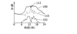
- FIG. 5 it is a figure explaining the mode of the maximum value of external commercial power when not using a charging / discharging control program by making only an external commercial power source into an electric power source.
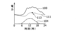
- FIG. 5 it is a figure explaining a mode that the maximum value of external commercial power falls by using the charging / discharging control program corresponding so that a time-dependent fluctuation
- FIG. 3 it is a figure explaining the mode of the maximum value of external commercial power when using the charging / discharging control program corresponding to the time-dependent fluctuation
- FIG. 5 it is a figure explaining a mode that the maximum value of external commercial power falls by using the charging / discharging control program corresponding so that a time-dependent fluctuation
- FIG. 3 it is a figure explaining the mode of the maximum value of external commercial power when using the charging / discharging
- a lithium ion battery will be described as the power storage device, but other secondary batteries may be used.
- a nickel hydrogen battery, a nickel cadmium battery, or the like may be used.
- a general home is described as a client system as an object of power management, but this is an example, and any system including a power storage device and having a load may be used. It may be a large-scale facility.
- solar power generation power and external commercial power will be described as power sources, a client system that does not use solar power generation and uses only external commercial power may be used.
- the model of power change with time described below is an example, and a model with other contents may be used.
- the power (kW) value, power amount (kWh) value, power charge, etc. described below are examples for explanation, and, of course, may vary depending on the contents of the client system, the external commercial power charge system, etc. It does not matter.
- nighttime charging of an in-vehicle secondary battery for an electric vehicle will be described as a change in the power consumption model of the load.
- this is an example for explanation, and other changes in the power consumption situation It may be.
- the client system is a factory facility, the power consumption model may be changed due to additional installation of equipment.
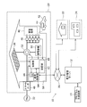
- FIG. 1 is a diagram illustrating a state of a power management system 10 including a power management device 58 that is a power management client device and a power management server 12.
- the configuration of the house 20 that is a client system including the power management device 58 that is a power management client device is shown in detail.
- a thick solid line indicates the flow of power
- a thin solid line with an arrow indicates a signal flow.
- this house 20 uses solar power generated by the solar battery 30 and external commercial power from an external commercial power source 32 provided by an external power company as power sources. Therefore, it is an electrification system having a home appliance load 40 such as lighting, kitchen appliances, audio-video appliances, air-conditioning appliances, and hot-water supply facilities.
- the house 20 includes a power storage device 50 and a power management device 58, and is a system that performs charge / discharge control to level the power supply of the power source in accordance with the required power status of the load of the home appliance load 40. Under such circumstances, its capacity is set and installed.
- the solar cell 30 is intended to supply power generated by photovoltaic power generation to the required power of the load of the house 20, and the generated power is consumed in the entire day of the house 20 or in the daytime during the daylight hours. It is set in consideration of consumption.
- the power generated by the solar battery 30 can be set to about 3 kW, for example.
- the external commercial power source 32 is a single-phase or three-phase AC power source, and is combined with power generated by various power generation methods such as hydroelectric power generation, nuclear power generation, and thermal power generation in accordance with fluctuations in power supply and demand. Supplied by a power company. In the following description, unless otherwise specified, it is assumed that the unit price of electric power is the same throughout the day for the sake of simplicity.
- the home appliance load 40 is used for life in the house 20 as described above, and generally has a high frequency of use in the daytime and a low frequency of use at midnight. For example, when the power consumption state of the home appliance load 40 is examined in association with the passage of time during the day, the power consumption is the lowest around 5:00 in the early morning, and the power consumption gradually increases with the passage of time. From 10:00 to 2 pm peak, and thereafter power consumption gradually decreases.
- the in-vehicle secondary battery 44 is a battery mounted on the electric vehicle 42, the electric vehicle 42 continues to discharge while the electric vehicle 42 is running, returns to the house 20 in the evening or at night, stops in the garage, and is provided in the electric vehicle 42.
- the connection port provided in the house 20 is connected to the power supply port, and charging is performed until the next morning. Therefore, when the power consumption state of the in-vehicle secondary battery 44 through the connection port of the house 20 is examined in association with the passage of time during the day, the charging is completed from about 10 o'clock on the night when charging starts. The power consumption is almost constant until around 4 o'clock the next morning. Power consumption is not performed at other times.
- the individual supply power detection device 46 is a wattmeter provided in each electrical outlet of the house 20.
- the smart meter 48 is a wattmeter with a wireless transmission function provided at a power supply port where external commercial power is introduced into the house 20.
- the individual supply power detection device 46 the smart meter 48 may be used as it is, or a current probe type measurement device may be used.
- the detection data of the individual supply power detection device 46 and the detection data of the smart meter 48 are transmitted to the power management device 58 and used as load power consumption state data.
- the power consumption of the in-vehicle secondary battery 44 of the home appliance load 40 and the electric vehicle 42 which are loads can be obtained by subdividing each electric outlet, for example.
- the smart meter 48 connected to the external commercial power supply 32 cannot distinguish the power consumption for each type of load, but can acquire the entire value of the external commercial power supplied from the external commercial power supply 32. it can. Therefore, when the solar battery 30 is not used or when the photovoltaic power is smaller than the external commercial power, the detection data of the smart meter 48 can be regarded as the load power consumption state data.
- the power storage device 50 is a chargeable / dischargeable secondary battery in which a large number of lithium ion storage batteries are combined to obtain a desired storage capacity.
- the power storage capacity of the power storage device 50 is set in consideration of the power consumption of the entire house 20 in one day, the power consumption in the daytime, which is the daylight hours, and the like, similarly to the setting of the generated power of the solar battery 30.
- the power storage capacity of the power storage device 50 can be set to 20 kwh, for example.
- the state of the power storage device 50 is detected by a current detection unit, a voltage detection unit, and a temperature detection unit provided in the power storage device 50.
- a charging current and a discharging current of the power storage device 50 are detected by a current detection unit
- a voltage between terminals of the power storage device 50 is detected by a voltage detection unit
- a temperature of the power storage device 50 is detected by a temperature detection unit. Since the power storage device 50 is a combination of a plurality of unit storage batteries, a plurality of current detection units, voltage detection units, and temperature detection units may be provided for each power storage device 50.
- These detection data are transmitted to the power management device 58 and used as power storage device charge / discharge state data. Further, detection of an abnormal state of the power storage device 50 is also performed using these detection data.
- the power conversion device 52 converts power between the AC power of the external commercial power supply 32 and the DC power of the power storage device 50, or converts the voltage between the voltage of the solar cell 30 and the voltage of the power storage device 50, or the power storage device 50. And a converter such as a bidirectional AC / DC converter and a bidirectional DC / DC converter. Specifically, the type of converter to be used is selected according to the content of the conversion that is actually performed.
- the power conversion device 52 is connected to the power storage device 50 as described above, and performs charging / discharging of the power storage device 50 by its operation.
- the power management device 58 performs charge / discharge control of the power storage device 50 by the operation of the power conversion device 52.
- the power management device 58 is a device that manages charge / discharge power in the house 20 as a client system, and corresponds to a power management client device when compared with the power management server 12.
- the power management device 58 displays a control unit 60, a storage unit 62 that stores a charge / discharge control program, a communication control unit 64 that communicates with the power management server 12 via the network 16, and a degree of contribution of charge / discharge control. And a display unit 66. These elements are connected to each other by an internal bus.
- Such a power management device 58 can be composed of a suitable computer.
- the control unit 60 has a function of performing charge / discharge control of the power storage device 50 by executing a charge / discharge control program, and leveling the external commercial power supplied from the external commercial power supply 32 to the house 20. Specifically, the solar cell information on the power generation state of the solar cell 30 is acquired, the power storage device charge / discharge state data for the power storage device 50 is acquired, the data from the individual power supply detection device 46 and the data from the smart meter 48 Has a function of acquiring load power consumption state data for loads including. These data are acquired in association with the acquisition date and time.
- the power storage device 50 has a function of performing charge / discharge control of the power storage device 50 through the operation of the power conversion device 52 in accordance with the state of required power of the load using a charge / discharge control program stored in the storage unit 62. Thereby, leveling of the external commercial power from the external commercial power supply 32 is achieved.
- the control unit 60 further has the following functions. That is, it has a power storage device data transmission function for transmitting power storage device charge / discharge state data to the power management server 12 and a load data transmission function for transmitting load power consumption state data to the power management server 12. Further, it has a power data transmission function for transmitting power generation state data of the solar battery 30 and external commercial power supply state data from the external commercial power source 32. In addition, a program receiving function for receiving a charge / discharge control program generated based on the power storage device charge / discharge state data and the load power consumption state data from the power management server 12, and an existing charge / discharge already stored in the storage unit 62 It has a program change function for changing the control program to the received charge / discharge control program.
- the changed charge / discharge control program When the charge / discharge control program is changed, the changed charge / discharge control program is used thereafter. Moreover, it has the contribution display function which displays the contribution before and behind the change of a charging / discharging control program on the display part 66.
- FIG. Such a function can be realized by executing software, and specifically, can be realized by executing a corresponding power management program. A part of the above functions may be realized by hardware.
- the power management server 12 is a server device that can communicate with the house 20 as a client system via the network 16.
- the power management server 12 can communicate with the client systems 22 and 24 other than the house 20 via the network 16.
- the client systems 22 and 24 other than the house 20 include a power storage device and a power management device.
- the power management server 12 includes the program generation unit 14 and is based on the storage device charge / discharge state data and the load power consumption state data received via the communication control unit 64 of the power management device 58 of the house 20. It has a function of generating a charge / discharge control program so as to adapt to the current required power situation.
- the power management server 12 can be connected to the network 16 and can be composed of a computer with a mass storage device suitable for data storage and program creation.
- the power management server 12 has the following functions for generating the charge / discharge control program. That is, the power storage device data receiving function for receiving the power storage device charge / discharge state data of the power storage device 50 from the power management device 58, and the load on the loads such as the home appliance load 40 and the in-vehicle secondary battery 44 from the power management device 58 It has a load data receiving function for receiving power consumption state data.
- the power management device 58 has a power supply data receiving function for receiving the power generation state data of the solar battery 30 and the external commercial power supply state data from the external commercial power supply 32.
- a charge / discharge control program generation function for generating a charge / discharge control program based on the power storage device charge / discharge state data and load power consumption state data, and a program transmission function for transmitting the generated charge / discharge control program to the power management device 58
- Such a function can be realized by executing software. Some of these functions may be realized by hardware.
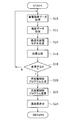
- FIG. 2 is a flowchart illustrating a procedure in which a charge / discharge control program is generated by the program generation unit 14 and transmitted to the power management apparatus 58 via the network 16, and the existing charge / discharge control program is changed in the storage unit 62. is there.
- Each procedure corresponds to each processing procedure of the charge / discharge control program generation software.
- the power management device 58 transmits the power storage device charge / discharge state data via the network 16, and receives and acquires it (S10).
- the acquired data is stored in association with the date and time.
- This step is executed by the power storage device data reception function of the power management server 12.
- load power consumption state data is transmitted from the power management apparatus 58 via the network 16, and is received and acquired (S12).
- the acquired data is stored in association with the date and time.
- This step is executed by the load data reception function of the power management server 12.
- the power management device 58 transmits the power generation state data of the solar cell 30 and the external commercial power supply state data from the external commercial power supply 32, receives and acquires them, and acquires the acquired data. , Store in association with the date and time.
- an optimal charge / discharge model for generating the charge / discharge control program is generated based on the acquired power storage device charge / discharge state data and load power consumption state data (S14). Specifically, daily load data that is daily data of the load power consumption state associated with the passage of time during the day is generated, and the storage that is associated with the passage of time during the day Daily aging power storage device data, which is data for each day in the device charge / discharge state, is generated. These generations are performed by editing the data stored in association with the date and time. Needless to say, the acquired data may be processed in real time and edited every time.
- the charging of the power storage device 50 by the power supply from the external commercial power supply 32 is promoted in the time zone in which the load power consumption is low in the daily time-lapse load data, and the load power consumption is high.
- the power stored in the power storage device 50 is discharged to the belt and supplied to the load so that the charge power amount and the discharge power amount of the power storage device 50 throughout the day are the same.
- charging / discharging the power storage device 50 charging is performed when the charge state is equal to or less than a predetermined charge limit value while referring to the daily time-lapse power storage device data which is the power storage device charge / discharge state data every moment.
- Discharging is performed when the state of charge is equal to or greater than a predetermined discharge limit value, so that the power storage device 50 is not overcharged or overdischarged.
- a leveled charge / discharge model that suppresses the level of power supply from the external commercial power supply 32 and leveles it is generated.
- the suppression of the peak of power supply from the external commercial power supply 32 is preferably a peak suppression throughout the day, but in some cases, it may be a peak suppression during a certain period of the day. For example, peak suppression during the daytime may be used.
- This leveled charge / discharge model corresponds to the optimum charge / discharge model.
- the solar power generated by the solar battery 30 is first addressed to the required power of the load throughout the day, and the shortage is externally As a supplement to the external commercial power from the commercial power source 32, it is conceivable to achieve leveling by charging and discharging the power storage device 50 so that the external commercial power has a constant power value throughout the day. In this case, the power supplied to the load is obtained by adding daytime photovoltaic power to a constant value of external commercial power.
- the average value of the required power of the load throughout the day is obtained, and the supply power to the load is made constant by using the charge / discharge of the power storage device 50. It may be possible to cover the amount of solar power generated by external commercial power. In this case, the power supplied to the load is a constant value throughout the day, and the external commercial power is sufficient to supply the amount of solar power generated from the constant value in the daytime.
- the data that is the basis for calculating the optimal charge / discharge model is daily aging load data as described above.
- This daily aging load data is preferably based on several days of data rather than one day of data.
- a simple average method, a weighted average method, a moving average method, or the like can be used to process data from several days into one daily time-dependent load data.
- the data for each day may be gradually increased or decreased according to the progress of the season according to the characteristic.
- the calculated optimum charge / discharge model is compared with the charge / discharge model that is the basis when the conventional charge / discharge control program is generated (S16).
- the comparison is performed for the power value of the external commercial power that is constant in the optimum charge / discharge model and the power value of the external commercial power in the conventional charge / discharge model. For example, if the power value of the external commercial power in the optimal charge / discharge model is lower than the power value of the external commercial power in the conventional charge / discharge model, the optimal charge / discharge model is This is preferable to the discharge model.
- a charge / discharge control program for realizing the optimum charge / discharge model is generated (S20). Specifically, the procedure for charging or discharging the power storage device 50 through the operation control of the power conversion device 52 is programmed along the time series of the day. For example, the procedure of charging the power storage device 50 from the solar cell 30 with ZZkW from XX to YY is programmed. This process is executed by the charge / discharge control program generation function of the power management server 12.
- the generated charge / discharge control program is transmitted to the power management apparatus 58 via the network 16, and the existing charge / discharge control program stored in the storage unit 62 is transmitted in the power management apparatus 58.
- the program is changed to a new charge / discharge control program (S22).
- This process is executed by the program transmission function on the power management server 12 side, and is executed by the program reception function and the program change function on the power management apparatus 58 side.
- it is determined which charge / discharge control program in the existing is to be changed to a new charge / discharge control program, and a new one is determined according to the determination. Changes to the charge / discharge control program are made.
- the effects such as the degree of contribution before and after the change of the charge / discharge control program are calculated and output and displayed on the display unit 66 on the power management device 58 side (S24). This process is executed by the contribution display function of the power management device 58. Thereafter, the process returns to S10.
- the power management device 58 may be provided with a start button or a start menu for starting the change procedure. In that case, according to the request
- the contents of equipment such as the power storage device 50 and the home appliance load 40 change, the change may be detected and a procedure related to the change of the charge / discharge control program may be executed. In this way, an appropriate charge / discharge control program is generated according to the required power status of the load of the house 20 and is changed in place of the existing one. Even if the required power status of the load changes, it is possible to flexibly cope with the change.
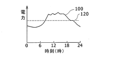
- the horizontal axis indicates the time of the day
- the vertical axis indicates the power, which shows how the power varies during the day.
- the solid lines are the load power characteristic lines 100 and 140 indicating the power consumption of the load in the house 20.
- 3 and 4 compare the differences between the case where the solar cell 30 and the external commercial power source 32 are used as the power source and the power storage device 50 is not used in the house 20.
- the load in the house 20 is only the home appliance load 40, and the in-vehicle secondary battery 44 of the electric vehicle 42 is not considered.
- FIG. 3 is a diagram for explaining a case where the photovoltaic power generation power of the solar battery 30 and the external commercial power of the external commercial power supply 32 correspond to the required load power without using the power storage device 50.
- FIG. 4 is a diagram illustrating a case where appropriate charge / discharge control is performed using the power storage device 50 and external commercial power and solar power generated power correspond to load required power.
- the power storage device 50 is used only to absorb the fluctuation of the solar power generated by the solar cell 30 and is not used to absorb the fluctuation of the external commercial power of the external commercial power supply 32.
- the solid line is the load power characteristic line 100 as described above
- the one-dot chain line is the photovoltaic power generation characteristic line 102
- the broken line is the external commercial power characteristic line 110.
- the external commercial power value (load power value ⁇ solar power generation value) at each time. Since the photovoltaic power generation value fluctuates due to sunshine, the maximum value 112 of the external commercial power value is almost the same as the maximum value of the load power value in the example of FIG.
- the dashed-dotted solar power generation characteristic line 104 is smooth with respect to the time.
- the characteristic is shown.
- the power storage device 50 is used only for suppressing fluctuations in the photovoltaic power generation, and as a result, the broken external commercial power characteristic line 111 also has a smooth characteristic, and its maximum value 113 is the maximum value 112 in FIG. Compared to, the value is significantly smaller. In this way, by using the power storage device 50 and appropriately performing the charge / discharge control, the maximum value of the external commercial power is greatly reduced by the solar power generated by the solar battery 30, for example, the basic charge of the external commercial power Can be reduced.
- FIG. 5 and FIG. 6 compare the differences between the case of using the external commercial power supply 32 as the power source and the case of not using the power storage device 50 in the house 20.
- the load in the house 20 is only the home appliance load 40, and the in-vehicle secondary battery 44 of the electric vehicle 42 is not considered.
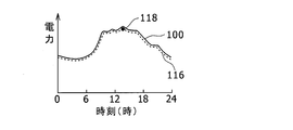
- FIG. 5 is a diagram for explaining a case where the load demand power is supported by the external commercial power of the external commercial power supply 32 without using the power storage device 50.
- FIG. 6 is a diagram for explaining a case in which appropriate charge / discharge control is performed using the power storage device 50, and fluctuations in external commercial power are suppressed to support load demand power.
- the solid line is the load power characteristic line 100 as described above, and the broken line is the external commercial power characteristic line 116.
- the fluctuation of the external commercial power with the time is leveled by appropriate charge / discharge control of the power storage device 50.
- the power storage capacity of the power storage device 50 is sufficient, the amount of charge power and the amount of discharge power of the power storage device 50 are made the same with respect to fluctuations in the power consumption state of the load throughout the day.
- the power can be constant throughout the day.
- the power storage device 50 is charged by supplying power from the external commercial power supply 32 during a time when the load power consumption is low throughout the day, and the power stored in the power storage device 50 is discharged during the time when the load power consumption is high.
- the charging power amount and the discharging power amount throughout the day are made the same.
- a line having a constant power value is drawn, and the area where the load power characteristic line 100 is located below the line is defined as the charge power amount.
- the power line having a constant value is moved up and down so that the area on the lower side and the area on the upper side are the same.
- a power line having the same area as the lower side and the upper side indicates the value of the external commercial power that balances the charging power amount and the discharging power amount of the power storage device 50 throughout the day.
- the external commercial power characteristic line 120 obtained in this way is indicated by a broken line.
- the external commercial power has the same power value throughout the day.
- the external commercial power can be leveled to a constant value even if the load power varies.
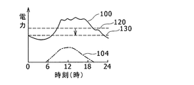
- the photovoltaic power generation of the solar battery 30 and the external commercial power of the external commercial power supply 32 are used as power sources, and the power storage device 50 is used to change the fluctuation of the photovoltaic power generation and the fluctuation of the external commercial power. It is a figure which shows the case where both are suppressed.
- the load in the house 20 is only the home appliance load 40, and the in-vehicle secondary battery 44 of the electric vehicle 42 is not considered.
- FIG. 7 corresponds to a state in which solar power generated by the solar cell 30 can be used in addition to the case of FIG.
- the value of the photovoltaic power generation characteristic line 104 is subtracted from the value of the load power characteristic line 100 at each time.
- the result is the same as that of the external commercial power characteristic line 111 in FIG.
- the procedure described in FIG. 6 is executed for the external commercial power characteristic line 111.
- a line having a constant power value is drawn with respect to the external commercial power characteristic line 111, and the area where the external commercial power characteristic line 111 is located below the line is defined as the charging power amount.
- the power line having a constant value is moved up and down so that the area on the lower side and the area on the upper side are the same.
- the power line having the same area as the lower side and the upper side is the external commercial power characteristic line 130 indicating the value of the external commercial power at which the charging power amount and the discharging power amount of the power storage device 50 are balanced throughout the day.
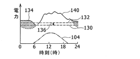
- FIG. 8 shows a case where the in-vehicle secondary battery 44 is charged by purchasing the electric vehicle 42 as compared with FIG.
- FIG. 7 shows the time when the solar battery 30 is introduced
- FIG. 8 shows the current state. Then, a charge / discharge control program is set so as to be suitable for the state of FIG. 7, and the charge control program is currently stored in the storage unit 62 of the power management device 58 as described in FIG. The charge / discharge control is performed.
- the charging of the in-vehicle secondary battery 44 of the electric vehicle 42 is provided in the house 20 at the power supply port provided in the electric vehicle 42 after the user returns to the house 20 in the evening or at night and stops in the garage. This is done by connecting the connected port. If the electric vehicle 42 is charged with 15 kwh per day, it fits the user's life pattern. According to the charging specification of the electric vehicle 42, it is preferable to charge it for about 5-6 hours. is there. Note that this is an example of description, and of course, the electric vehicle 42 under other charging conditions may be used.
- the solid line is the load power characteristic line 140 when charging the in-vehicle secondary battery 44 at night.
- the increased power 134 for charging the in-vehicle secondary battery 44 is a hatched portion.
- the external commercial power characteristic line 132 is obtained by obtaining a constant power value line that balances the charging power amount and the discharging power amount of the power storage device 50. .
- the external commercial power supplied from the external commercial power supply 32 is optimized. Change can be minimized.
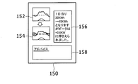
- FIG. 9 is a display for displaying the contribution degree before and after the change on the display unit 66 when the charge / discharge control program of the power storage device 50 is changed in response to the change in the required load power in FIGS. 7 to 8. It is a figure which shows an example of the screen. Here, a power characteristic diagram 152 according to a conventional charge / discharge control program and a power characteristic diagram 154 according to a modified charge / discharge control program are shown. In this case, the power characteristic diagram 152 is a diagram corresponding to the content of FIG. 7, and the power property diagram 154 is a diagram corresponding to the content of FIG. 8.
- the advice column 158 is a proposal column that describes the content that if the user can execute such a thing, further effective energy saving can be achieved. For example, when there is a device that consumes a large amount of power in a short time, it is possible to make a proposal such that the use time of the device is slightly shifted so that it does not overlap with the time when the power consumption of other loads is large.
- the power consumption state data of the entire load of the house 20 is used as the load power consumption state data. If the individual supply power detection device 46 described with reference to FIG. 1 is used, fine charge / discharge control can be performed for each individual load. That is, the individual supply power supplied to each of the plurality of power consuming devices constituting the load of the house 20 is detected by the individual supply power detection device 46, and the daily supply is the data for each day for the individual supply power. Create load data. This is compared with an overall load power characteristic line for the entire load as an individual load power characteristic line for each individual supply power. The overall load power characteristic lines are the load power characteristic lines 100 and 140 described with reference to FIGS. Based on the result of the comparison, it is possible to determine the priority of power allocation to individual loads.
- the power allocation priority for a load with a large amount of power.
- the power allocation priority when there is a margin in the stored power of the power storage device 50 during a time period when the overall load power consumption is large, the power is stored in a load having a large individual supply power among a plurality of loads. It is assumed that the stored power of the device 50 is allocated with priority. Conversely, when there is no margin in the stored power of the power storage device 50, the allocation of the stored power from the power storage device 50 to a load with a large individual supply power is limited. Thus, by using the detection data of the individual supply power, it is possible to perform fine charge / discharge control that matches the characteristics of the individual load.
- one power management server 12 receives power storage device charge / discharge state data, load power consumption state data, power supply data, and the like from the power management device 58 of the house 20 as a client system, and based on the data.
- the new charge / discharge control program is generated, but these functions may be executed by a plurality of servers.
- one server receives and manages power storage device charge / discharge state data from the power management device 58 of the house 20, and another server loads load power consumption state data from the power management device 58 of the house 20.
- the other one server receives and manages the power supply data from the power management device 58 of the house 20, and another power management server 12 receives necessary data from these servers.
- a new charge / discharge control program can be generated.
- the number of servers other than the above example may be used.
- the power management server 12 has been described with a focus on the function of generating the charge / discharge control program.
- the power management server 12 receives data on the power source, load, and power storage device from the power management device 58.
- This can be used as a data center or a monitoring center related to the power management of the client system.
- it can be used for recording the usage history of the solar cell 30 and the power storage device 50, detecting abnormality, etc., and in some cases, it can also be used for recording the usage history of the home appliance load 40 or the in-vehicle secondary battery 44, detecting abnormality, etc. Can do.
- FIG. 10 is a diagram illustrating a configuration in which a charge / discharge control program is generated by the program generation device 15 connected to the power management server 12. Communication between the power management server 12 and the program generation device 15 may be performed via a dedicated line or may be performed via the network 16. Even in this case, the data from the power management apparatus 58 is received by the power management server 12 via the network 16 and transmitted from the power management server 12 to the program generation apparatus 15. The charge / discharge control program generated by the program generation device 15 is transmitted from the power management server 12 to the power management device 58 via the network 16. However, in this case, the program generation device 15 may directly transmit to the power management device 58 via the network 16.
- the power management server 12 is described as generating one optimum charge / discharge control program according to the optimum charge / discharge model based on the power storage device charge / discharge state data and the load power consumption state data. Instead, the power management server 12 prepares in advance a plurality of charge / discharge models generated based on the power storage device charge / discharge state data and the load power consumption state data, and presents the plurality of charge / discharge models to the user. Thus, the user can be given a degree of freedom as to which charge / discharge model to select. When presenting a plurality of charge / discharge models to the user, the contribution of each charge / discharge model may be presented together. As shown in FIGS.
- the power management device 58 includes a model display unit that displays a plurality of charge / discharge models generated by the power management device 12, and a plurality of models displayed by the user in the model display unit. It has a model transmission part which acquires that one charging / discharging model was selected from the charging / discharging model, and transmits the selected charging / discharging model to the power management server 12. The user may select the optimum charge / discharge model, or may select another charge / discharge model.
- the model display unit can also serve as the display unit 66, and the model transmission unit can be included in the control unit 60.
- the program receiving part in the control part 60 of the power management apparatus 58 receives from the power management server 12 the charging / discharging control program produced
- the program changing unit changes the existing charge / discharge control program to the received charge / discharge control program, that is, the selected charge / discharge control program corresponding to the charge / discharge model selected by the user. By doing so, user convenience is improved.
- the load power consumption state data has been described for all of the plurality of power consumption devices in the house 20.
- a power consuming apparatus including a home appliance load 40 such as a lighting, a kitchen appliance, an audio video device, an air conditioner, a hot water supply facility, and an in-vehicle secondary battery 44 of an electric vehicle 42 is considered.
- a specific power consuming device that the user pays attention to, and the charge / discharge control program is generated based on the load power consumption state data of the specific power consuming device and the power storage device charge / discharge state data. Good.
- the power management device 58 includes a mark display unit that displays a plurality of device marks that are marks for distinguishing a plurality of power consuming devices constituting the load.
- the device mark can be a mark that visually indicates lighting, kitchen appliances, audio-video equipment, air-conditioning / heating appliances, hot-water supply equipment, and the in-vehicle secondary battery 44 of the electric vehicle 42.
- the mark display unit can also serve as the display unit 66 described in FIG.
- the load data transmission unit in the control unit 60 of the power management apparatus 58 acquires that one device mark has been selected from the plurality of device marks by the user in the mark display unit, and corresponds to the selected device mark.
- Load power consumption state data for the power consuming device is transmitted to the power management server 12.
- the program receiving part in the control part 60 of the power management apparatus 58 is a charge / discharge control program generated based on the load power consumption state data for the selected power consumption apparatus and the power storage apparatus charge / discharge state data.
- the program change unit changes the existing charge / discharge control program to the received charge / discharge control program, that is, the charge / discharge control program corresponding to the power consuming device selected by the user. By doing so, user convenience is improved.
- FIG. 11 is a diagram showing a configuration of the power management system 11 having such a power management apparatus 57. As shown in FIG.
- the power management device 57 includes a control unit 59, a storage unit 61 that stores a charge / discharge control program, an input unit 63 that inputs necessary data and the like, a communication control unit 64 that communicates with the outside via the network 16, And a display unit 66 for displaying the degree of contribution of charge / discharge control and the like. These elements are connected to each other by an internal bus.
- the power management device 57 can be configured by a suitable computer.
- the control unit 59 has a function of performing charge / discharge control of the power storage device 50 by executing a charge / discharge control program, and leveling the external commercial power supplied from the external commercial power supply 32 to the house 20. Specifically, the solar cell information on the power generation state of the solar cell 30 is acquired, the power storage device charge / discharge state data for the power storage device 50 is acquired, the data from the individual power supply detection device 46 and the data from the smart meter 48 Has a function of acquiring load power consumption state data for loads including. These data are acquired in association with the acquisition date and time.
- the charge / discharge control program stored in the storage unit 61 is used to perform charge / discharge control of the power storage device 50 through the operation of the power conversion device 52 in accordance with the required power state of the load. Thereby, leveling of the external commercial power from the external commercial power supply 32 is achieved.
- the control unit 59 further has the following functions. That is, a program generation function for generating a charge / discharge control program based on the power storage device charge / discharge state data and load power consumption state data, and an existing charge / discharge control program already stored in the storage unit 61 are replaced with a new charge / discharge control.
- a program change function for changing to a program is provided.
- the control unit 59 also has an information acquisition function for acquiring information necessary for generating the charge / discharge control program via the network 16 and the communication control unit 64.
- power rate information 82 is shown as an example of information necessary for generating the charge / discharge control program.
- the power rate information 82 can be acquired from the power company, for example, via the network 16.
- a new charge / discharge control program 80 can be transmitted from an external program generation device or the like via the network 16 and the communication control unit 64.
- the program change function is configured so that the existing charge / discharge control program is replaced with the new charge / discharge control program from the outside according to the determination of the effect of the new charge / discharge control program 80 transmitted and acquired from outside. It has a function to change to 80.
- the changed charge / discharge control program When the charge / discharge control program is changed, the changed charge / discharge control program is used thereafter. Moreover, it has the contribution display function which displays the contribution before and behind the change of a charging / discharging control program on the display part 66.
- FIG. Such a function can be realized by executing software, and specifically, can be realized by executing a corresponding power management program. A part of the above functions may be realized by hardware.
- FIG. 2 can be used as a flowchart showing a procedure in which the charge / discharge control program is generated by the program generation function of the control unit 59 and the existing charge / discharge control program is changed in the storage unit 61.
- the main body that executes each procedure is different from the case of the power management system 10 described in FIG.
- Each procedure corresponds to each processing procedure of the charge / discharge control program generation software.
- the storage device charge / discharge state data is acquired from the storage device 50 (S10). Specifically, the acquisition is performed by receiving transmission of data detected by the current detection unit, the voltage detection unit, and the temperature detection unit provided in the power storage device 50. The acquired data is stored in association with the date and time. This step is executed by the power storage device data acquisition function of the control unit 59. Moreover, the load power consumption state data about the vehicle-mounted secondary battery 44 of the household appliance load 40 and the electric vehicle 42 are acquired (S12). Specifically, the acquisition is performed by receiving transmission of detection data detected by the individual supply power detection device 46. The acquired data is stored in association with the date and time. This process is executed by the load data acquisition function of the control unit 59. Further, if necessary, the power generation state data of the solar cell 30 is transmitted from the solar cell 30, and the external commercial power supply state data from the external commercial power supply 32 is acquired by the smart meter 48 by transmission. It is stored in association with the date and time.
- an optimal charge / discharge model for generating the charge / discharge control program is generated based on the acquired power storage device charge / discharge state data and load power consumption state data (S14). Specifically, daily load data that is daily data of the load power consumption state associated with the passage of time during the day is generated, and the storage that is associated with the passage of time during the day Daily aging power storage device data, which is data for each day in the device charge / discharge state, is generated. These generations are performed by editing the data stored in association with the date and time. Needless to say, the acquired data may be processed in real time and edited every time.
- the charging of the power storage device 50 by the power supply from the external commercial power supply 32 is promoted in the time zone in which the load power consumption is low in the daily time-lapse load data, and the load power consumption is high.
- the power stored in the power storage device 50 is discharged to the belt and supplied to the load so that the charge power amount and the discharge power amount of the power storage device 50 throughout the day are the same.
- charging / discharging the power storage device 50 charging is performed when the charge state is equal to or less than a predetermined charge limit value while referring to the daily time-lapse power storage device data which is the power storage device charge / discharge state data every moment.
- Discharging is performed when the state of charge is equal to or greater than a predetermined discharge limit value, so that the power storage device 50 is not overcharged or overdischarged.
- a leveled charge / discharge model that suppresses the level of power supply from the external commercial power supply 32 and leveles it is generated.
- the suppression of the peak of power supply from the external commercial power supply 32 is preferably a peak suppression throughout the day, but in some cases, it may be a peak suppression during a certain period of the day. For example, peak suppression during the daytime may be used.
- This leveled charge / discharge model corresponds to the optimum charge / discharge model.
- the solar power generated by the solar battery 30 is first addressed to the required power of the load throughout the day, and the shortage is externally As a supplement to the external commercial power from the commercial power source 32, it is conceivable to achieve leveling by charging and discharging the power storage device 50 so that the external commercial power has a constant power value throughout the day. In this case, the power supplied to the load is obtained by adding daytime photovoltaic power to a constant value of external commercial power.
- the average value of the required power of the load throughout the day is obtained, and the supply power to the load is made constant by using the charge / discharge of the power storage device 50. It may be possible to cover the amount of solar power generated by external commercial power. In this case, the power supplied to the load is a constant value throughout the day, and the external commercial power is sufficient to supply the amount of solar power generated from the constant value in the daytime.
- the data that is the basis for calculating the optimal charge / discharge model is daily aging load data as described above.
- This daily aging load data is preferably based on several days of data rather than one day of data.
- a simple average method, a weighted average method, a moving average method, or the like can be used to process data from several days into one daily time-dependent load data.
- the data for each day may be gradually increased or decreased according to the progress of the season according to the characteristic.
- the calculated optimum charge / discharge model is compared with the charge / discharge model that is the basis when the conventional charge / discharge control program is generated (S16).
- the comparison is performed for the power value of the external commercial power that is constant in the optimum charge / discharge model and the power value of the external commercial power in the conventional charge / discharge model. For example, if the power value of the external commercial power in the optimal charge / discharge model is lower than the power value of the external commercial power in the conventional charge / discharge model, the optimal charge / discharge model is This is preferable to the discharge model.
- a charge / discharge control program for realizing the optimum charge / discharge model is generated (S20). Specifically, the procedure for charging or discharging the power storage device 50 through the operation control of the power conversion device 52 is programmed along the time series of the day. For example, the procedure of charging the power storage device 50 from the solar cell 30 with ZZkW from XX to YY is programmed. This process is executed by the charge / discharge control program generation function of the control unit 59.
- the existing charge / discharge control program stored in the storage unit 61 is changed to the generated new charge / discharge control program (S22). This process is executed by the program changing function of the control unit 59.
- the effects such as the degree of contribution before and after the change of the charge / discharge control program are calculated and output and displayed on the display unit 66 (S24).
- This process is executed by the contribution display function of the control unit 59. Thereafter, the process returns to S10.
- the charge / discharge control program is generated by the program generation function of the control unit 59, and the existing charge / discharge control program is changed in the storage unit 61.
- the power management device 57 has been described as generating one optimum charge / discharge control program according to the optimum charge / discharge model based on the power storage device charge / discharge state data and the load power consumption state data. Instead, a plurality of charge / discharge models generated based on the power storage device charge / discharge state data and the load power consumption state data are prepared in advance, and the plurality of charge / discharge models are presented to the user to determine which charge to the user. A degree of freedom in selecting a discharge model can be given. When presenting a plurality of charge / discharge models to the user, the contribution of each charge / discharge model may be presented together. As shown in FIGS.
- the power management apparatus 57 includes a model display unit that displays a plurality of charge / discharge models.
- the model display unit can also serve as the display unit 66 in FIG.
- the program generation unit acquires that one charge / discharge model has been selected from the plurality of charge / discharge models by the user in the model display unit, and generates a charge / discharge control program corresponding to the selected charge / discharge model. This is the selected charge / discharge control program.
- the user can select the optimum charge / discharge model, and can select other charge / discharge models.
- the program changing unit changes the existing charge / discharge control program to the generated charge / discharge control program, that is, the selected charge / discharge control program corresponding to the charge / discharge model selected by the user. By doing so, user convenience is improved.
- the load power consumption state data has been described for all of the plurality of power consumption devices in the house 20.
- a power consuming device including lighting, kitchen appliances, audio-video appliances, air-conditioning appliances, home appliance loads 40 such as hot water supply facilities, and in-vehicle secondary batteries 44 of electric vehicles 42 is considered. ing. This is limited to a specific power consuming device that the user pays attention to, and the charge / discharge control program is generated based on the load power consumption state data of the specific power consuming device and the power storage device charge / discharge state data. Good.
- the power management device 57 includes a mark display unit that displays a plurality of device marks that are marks for distinguishing a plurality of power consuming devices constituting the load.
- the device mark can be a mark that visually indicates lighting, kitchen appliances, audio-video equipment, air-conditioning / heating appliances, hot-water supply equipment, and the in-vehicle secondary battery 44 of the electric vehicle 42.
- the mark display unit can also serve as the display unit 66 in FIG.
- the program generation unit of the control unit 59 acquires that one device mark has been selected from a plurality of device marks by the user in the mark display unit, and loads on the power consuming device corresponding to the selected device mark A charge / discharge control program is generated based on the power consumption state data and the power storage device charge / discharge state data. And a program change part changes the existing charging / discharging control program into the produced
- the power management apparatus can be used for power management of houses, factory facilities, and the like including a power storage device and at least a load driven by power supplied by the power storage device.
Landscapes
- Engineering & Computer Science (AREA)
- Power Engineering (AREA)
- Manufacturing & Machinery (AREA)
- Chemical & Material Sciences (AREA)
- Chemical Kinetics & Catalysis (AREA)
- Electrochemistry (AREA)
- General Chemical & Material Sciences (AREA)
- Microelectronics & Electronic Packaging (AREA)
- Supply And Distribution Of Alternating Current (AREA)
- Charge And Discharge Circuits For Batteries Or The Like (AREA)
Abstract
住宅(20)は、太陽電池(30)による太陽光発電電力と、外部商用電源(32)からの外部商用電力とを電力源とし、家電負荷(40)等で電力を消費する。この住宅(20)は、蓄電装置(50)と電力管理装置(58)を備え、家電負荷(40)等の負荷の必要電力状況に合わせ、電力源の電力供給を平準化する充放電制御を行う。負荷の必要電力状況が変化した場合は、電力管理装置(58)からネットワーク(16)を介して、蓄電装置充放電状態データと、負荷電力消費状態データ等が電力管理サーバ(12)に送られ、電力管理サーバ(12)のプログラム生成部(14)で、新しい充放電制御プログラムが生成され、ネットワーク(16)を介して電力管理装置(58)に送られて既存の充放電制御プログラムが変更される。
Description
本発明は、電力管理装置に係り、特に、電力管理における負荷状況が変化したときに、蓄電装置の充放電制御を適切に行うことができる電力管理装置に関する。
電力管理において、負荷の電力消費に合わせて、発電や送電を効率的に行うことが好ましい。例えば、特許文献1には、ネットワークシステムの電源システムとして、通信回線に接続された複数の太陽光発電電源システムと、日射量等の気象情報を測定し、太陽光発電電源システムに送信する情報源装置とを含む構成が述べられている。これによって、高精度に予測された発電量に基づいて負荷装置の駆動を効率よく行うことができると述べられている。
また、特許文献2には、ユーティリティの消費電力の監視装置として、スマートメータシステムやトランシーバから情報を受信し、発光型ディスプレイを介して、現在の使用状況、現在の消費コスト、消費速度を視覚的に表示することが述べられている。
ところで、負荷の電力消費が変動する場合、ピーク電力が過大となって電力料金が高額になることがあり、また、電力供給がそれに対応しきれないことも生じ得る。蓄電装置はこの電力需給を平均化するために用いることができる。蓄電装置としては、リチウムイオン電池のような2次電池を用いることができる。
特許文献3には、リチウムイオン電池の管理装置として、リチウムイオン電池の充放電電流の測定値、温度の測定値、商用電源の給電の情報に基づいて、リチウムイオン電池の充放電の状態を判断し、リチウムイオン電池の残存容量を算出することが述べられている。
環境にやさしい電力源として、太陽電池による太陽光発電電力を利用することが進められている。住宅や工場等の施設に太陽電池を導入する際には、例えば、その施設における設備等の負荷の必要電力が平準化するように、太陽電池の容量等を初期設定する。ところが、住宅の場合には、ユーザの生活パターンが変化することがあり、また、工場等では設備等が変更となることがある。
このように、負荷状況等が変化すると、以前に設定した条件のままでは、負荷の必要電力の平準化が崩れ、負荷状況等の変化前には見られなかった消費電力の時間的なピークが発生することが生じる。そのために、当初の想定を上回る外部商用電力の供給を受けることになる。このように、一旦設定された電力管理システムは、その前提条件である負荷状況等が変化すると、そのままではその変化に対応することが困難である。
本発明の目的は、電力管理における負荷状況等が変化しても、その変化に柔軟に対応できる電力管理装置を提供することである。
本発明に係る電力管理装置は、蓄電装置と少なくとも蓄電装置により供給される電力により駆動される負荷とを含むシステムにおける充放電電力を管理する電力管理装置であって、既に有している既存充放電制御プログラムを、蓄電装置についての蓄電装置充放電状態データと、前記負荷についての負荷電力消費状態データとに基づいて生成された充放電制御プログラムに変更するプログラム変更部と、変更された充放電制御プログラムに従って、少なくとも外部商用電源からの充電電力によって蓄電装置を充電し、または蓄電装置の蓄電電力を放電して負荷を駆動する電力管理部と、を有することを特徴とする。
上記構成によれば、電力管理装置は、既に有している既存充放電制御プログラムを、蓄電装置充放電状態データと、負荷電力消費状態データとに基づいて生成された新しい充放電制御プログラムに変更する。このように、常に新しい充放電制御プログラムを用いることで、負荷状況等が変化しても、その変化に柔軟に対応することが可能となる。
以下に図面を用いて、本発明に係る実施の形態を詳細に説明する。以下では、蓄電装置としてリチウムイオン電池を説明するが、これ以外の2次電池であってもよい。例えばニッケル水素電池、ニッケルカドミウム電池等であってもよい。
また、以下では、電力管理の対象としてのクライアントシステムとして、一般的な家庭の住宅を説明するが、これは一例であって、蓄電装置を備え負荷を有するシステムであればよく、商店、工場、大規模施設等であってもよい。また、電力源として、太陽光発電電力と外部商用電力を説明するが、太陽光発電を利用せず、もっぱら外部商用電力のみを用いるクライアントシステムであってもよい。
また、以下で述べる電力の経時変化のモデルは一例であって、これ以外の内容のモデルであってもよい。また、以下で述べる電力(kW)の値、電力量(kWh)の値、電力料金等は説明のための一例であって、勿論クライアントシステムの内容、外部商用電力の料金体系等によって異なる値であっても構わない。また、以下では、負荷の電力消費モデルの変化として、電気自動車の車載用2次電池の夜間充電を説明するが、これは説明のための1例であって、これ以外の電力消費状況の変化であってもよい。例えば、クライアントシステムが工場施設の場合、設備の追加設置等による電力消費モデルの変化であっても構わない。
また、以下では、全ての図面において同様の要素には同一の符号を付し、重複する説明を省略する。また、本文中の説明においては、必要に応じそれ以前に述べた符号を用いるものとする。
図1は、電力管理クライアント装置である電力管理装置58と電力管理サーバ12とを含む電力管理システム10の様子を示す図である。ここでは、電力管理クライアント装置である電力管理装置58を備えるクライアントシステムである住宅20の構成が詳細に示されている。なお、図1において、太い実線は電力の流れを示し、細い実線で矢印が付されているのは信号の流れを示す。
この住宅20は、電力源として、太陽電池30による太陽光発電電力と、外部の電力会社から提供される外部商用電源32からの外部商用電力とを利用し、電力を消費する負荷としては、従来から、照明、厨房器具、オーディオビデオ機器、冷暖房器具、給湯設備等の家電負荷40を有している電化システムである。この住宅20は、蓄電装置50と電力管理装置58を備え、家電負荷40の負荷の必要電力状況に合わせ、電力源の電力供給を平準化する充放電制御を行うシステムであり、太陽電池30は、このような状況の下でその容量が設定されて設置されている。ところで、最近、この住宅20のユーザが電気自動車42を購入したため、その車載用2次電池44の充電が負荷として増加した事情がある。
太陽電池30は、太陽光発電による電力を住宅20の負荷の必要電力に供給しようとするもので、その発電電力は、住宅20の一日間全体における電力消費や、日照時間帯である昼間の電力消費等を考慮して設定される。住宅20が一般的な家庭の場合、太陽電池30の発電電力を例えば、3kw程度に設定することができる。
外部商用電源32は、単相または三相の交流電力源であり、電力需給の変動に合わせて、水力発電、原子力発電、火力発電等の様々な発電方式で発電された電力を組み合わせて、外部の電力会社から供給される。なお、以下では、特に断らない限り、説明を簡単にするため、一日を通して電力量単価は同じであるとする。
家電負荷40は、上記のように住宅20における生活に用いられるもので、一般的には昼間に使用頻度が高く、深夜には使用頻度が低いものが多い。例えば、家電負荷40の電力消費状態を一日の中の時間経過に対応付けて調べてみると、早朝5時前後が最も電力消費が低く、これから時間の経過と共に電力消費が次第に増加し、午前10時から午後2時の間がピークとなり、その後は次第に電力消費が低下する傾向を示す。
車載用2次電池44は、電気自動車42に搭載される電池であるので、電気自動車42が走行中は放電を続け、夕方あるいは夜間に住宅20に戻って車庫に停車後、電気自動車42に設けられる給電口に、住宅20に設けられた接続口を接続し、翌朝まで充電が行われる。したがって、住宅20の接続口を通しての車載用2次電池44の電力消費状態を一日の中の時間経過に対応付けて調べてみると、充電が開始される夜の10時前後から充電が完了する翌朝4時前後までの間、ほぼ一定の電力消費となる。それ以外の時間では電力消費が行われない。
個別供給電力検出装置46は、住宅20の電気コンセントにそれぞれ設けられる電力計である。スマートメータ48は、外部商用電力が住宅20に導入される給電口に設けられる無線送信機能付電力計である。個別供給電力検出装置46は、スマートメータ48をそのまま用いてもよく、あるいはカレントプローブ型の測定装置を用いてもよい。個別供給電力検出装置46のそれぞれの検出データと、スマートメータ48の検出データは、電力管理装置58に伝送され、負荷電力消費状態データとして用いられる。
個別供給電力検出装置46を用いることで、負荷である家電負荷40、電気自動車42の車載用2次電池44の電力消費を、例えば電気コンセントごとに細分化して取得することができる。また、外部商用電源32に接続されるスマートメータ48は、負荷の種類ごとの電力消費を区別することはできないが、外部商用電源32から供給される外部商用電力の全体の値を取得することができる。したがって、太陽電池30を用いないとき、あるいは太陽光発電電力が外部商用電力に比較して小さいときは、スマートメータ48の検出データを、負荷電力消費状態データとみなして用いることができる。
蓄電装置50は、リチウムイオン蓄電池を多数組み合わせて、所望の蓄電容量とした充放電可能の2次電池である。蓄電装置50の蓄電容量は、太陽電池30の発電電力の設定と同様に、住宅20の一日間全体における電力消費や、日照時間帯である昼間の電力消費等を考慮して設定される。住宅20が一般的な家庭の場合、蓄電装置50の蓄電容量を例えば、20kwhと設定することができる。
蓄電装置50の状態は、蓄電装置50に設けられた電流検出部、電圧検出部、温度検出部によって検出される。例えば、蓄電装置50の充電電流、放電電流は電流検出部によって検出され、蓄電装置50の端子間電圧は電圧検出部で検出され、蓄電装置50の温度は温度検出部で検出される。蓄電装置50は複数の単位蓄電池を複数組み合わせたものであるので、電流検出部、電圧検出部、温度検出部は、1つの蓄電装置50に対し、それぞれ複数設けるものとしてもよい。これらの検出データは、電力管理装置58に伝送され、蓄電装置充放電状態データとして用いられる。またこれらの検出データを用いて、蓄電装置50の異常状態の検出等も行われる。
電力変換装置52は、外部商用電源32の交流電力と蓄電装置50の直流電力との間の電力変換、あるいは太陽電池30の電圧と蓄電装置50の電圧との間の電圧変換、あるいは蓄電装置50と負荷の電圧との間の電圧変換を行う機能を有し、双方向AC/DCコンバータ、双方向DC/DCコンバータ等のコンバータである。具体的には、実際に行われる変換の内容に応じて、用いられるコンバータの種類が選択される。電力変換装置52は、上記のように蓄電装置50と接続され、その動作によって、蓄電装置50の充放電を行わせるものである。電力変換装置52の動作による蓄電装置50の充放電制御は、電力管理装置58によって行われる。
電力管理装置58は、クライアントシステムである住宅20における充放電電力を管理する装置で、電力管理サーバ12と対比するときは、電力管理クライアント装置に相当する。電力管理装置58は、制御部60と、充放電制御プログラムを格納する記憶部62と、ネットワーク16を介して電力管理サーバ12と交信する通信制御部64と、充放電制御の貢献度等を表示する表示部66とを含んで構成される。これらの要素は相互に内部バスによって接続される。かかる電力管理装置58は、適当なコンピュータで構成することができる。
制御部60は、充放電制御プログラムを実行することによって、蓄電装置50の充放電制御を行い、外部商用電源32から住宅20に供給される外部商用電力の平準化を図る機能を有する。具体的には、太陽電池30の発電状態に関する太陽電池情報を取得し、蓄電装置50についての蓄電装置充放電状態データを取得し、個別供給電力検出装置46からのデータとスマートメータ48からのデータを含む負荷についての負荷電力消費状態データを取得する機能を有する。これらのデータは、取得の日時に関連付けて取得が行われる。また、記憶部62に格納される充放電制御プログラムを用いて、負荷の必要電力の状況に合わせ、電力変換装置52の動作を介して蓄電装置50の充放電制御を行う機能を有する。これによって、外部商用電源32からの外部商用電力の平準化が図られる。
制御部60は、さらに次の機能を有する。すなわち、電力管理サーバ12に対し蓄電装置充放電状態データを送信する蓄電装置データ送信機能と、電力管理サーバ12に対し負荷電力消費状態データを送信する負荷データ送信機能を有する。また、太陽電池30の発電状態データ、外部商用電源32からの外部商用電力供給状態データを送信する電源データ送信機能を有する。また、蓄電装置充放電状態データと負荷電力消費状態データとに基づいて生成された充放電制御プログラムを電力管理サーバ12から受信するプログラム受信機能と、記憶部62に既に格納されている既存充放電制御プログラムを、受信した充放電制御プログラムに変更するプログラム変更機能を有する。充放電制御プログラムが変更されると、以後は、変更された充放電制御プログラムが用いられる。また、充放電制御プログラムの変更前後での貢献度を表示部66に表示する貢献度表示機能を有する。かかる機能は、ソフトウェアを実行することで実現でき、具体的には、対応する電力管理プログラムを実行することで実現できる。上記機能の一部をハードウェアで実現するものとしてもよい。
電力管理サーバ12は、ネットワーク16を介してクライアントシステムである住宅20と交信することができるサーバ装置である。電力管理サーバ12は、住宅20以外のクライアントシステム22,24ともネットワーク16を介して交信できる。住宅20以外のクライアントシステム22,24も、住宅20と同様に、蓄電装置と電力管理装置とを備えている。
電力管理サーバ12は、プログラム生成部14を備え、住宅20の電力管理装置58の通信制御部64を介して受信した蓄電装置充放電状態データと負荷電力消費状態データとに基づいて、住宅20の現在の必要電力状況に適合するように充放電制御プログラムを生成する機能を有する。かかる電力管理サーバ12は、ネットワーク16に接続可能で、データ記憶およびプログラム作成に適した大容量記憶装置付コンピュータで構成することができる。
電力管理サーバ12は、充放電制御プログラム生成のために、次の機能を有する。すなわち、電力管理装置58から、蓄電装置50の蓄電装置充放電状態データを受信する蓄電装置データ受信機能と、電力管理装置58から、家電負荷40および車載用2次電池44等の負荷についての負荷電力消費状態データを受信する負荷データ受信機能を有する。また、電力管理装置58から太陽電池30の発電状態データと外部商用電源32からの外部商用電力供給状態データを受信する電源データ受信機能を有する。また、蓄電装置充放電状態データと負荷電力消費状態データとに基づいて充放電制御プログラムを生成する充放電制御プログラム生成機能と、生成した充放電制御プログラムを電力管理装置58に送信するプログラム送信機能を有する。かかる機能はソフトウェアを実行することで実現できる。これらの機能の一部をハードウェアで実現するものとしてもよい。
図2は、プログラム生成部14によって充放電制御プログラムが生成され、ネットワーク16を介して電力管理装置58に送信されて、記憶部62において既存の充放電制御プログラムが変更される手順を示すフローチャートである。各手順は、充放電制御プログラム生成ソフトウェアの各処理手順にそれぞれ対応する。
充放電制御プログラムを生成するには、ネットワーク16を介して、電力管理装置58から蓄電装置充放電状態データを送信してもらい、これを受信して取得する(S10)。取得したデータは、日時に関連付けて記憶される。この工程は、電力管理サーバ12の蓄電装置データ受信機能によって実行される。また、ネットワーク16を介して、電力管理装置58から、負荷電力消費状態データを送信してもらい、これを受信して取得する(S12)。取得したデータは、日時に関連付けて記憶される。この工程は、電力管理サーバ12の負荷データ受信機能によって実行される。また、必要に応じ、電力管理装置58から、太陽電池30の発電状態データと外部商用電源32からの外部商用電力供給状態データを送信してもらい、これを受信して取得し、取得したデータを、日時に関連付けて記憶する。
そして、取得した蓄電装置充放電状態データと負荷電力消費状態データとに基づいて充放電制御プログラム生成のための最適充放電モデルを生成する(S14)。具体的には、一日の中の時間経過に対応付けた負荷電力消費状態の各日ごとのデータである日毎経時負荷データを生成し、また、一日の中の時間経過に対応付けた蓄電装置充放電状態の各日ごとのデータである日毎経時蓄電装置データを生成する。これらの生成は、日時に関連付けて記憶されているデータを編集することで行われる。勿論、取得したデータをリアルタイムで処理し、逐時的編集を行うものとしてもよい。
次に、これらの日毎データに基づいて、日毎経時負荷データの中で負荷電力消費の少ない時間帯に外部商用電源32からの電力供給による蓄電装置50の充電を促進し、負荷電力消費の多い時間帯に蓄電装置50の蓄電電力を放電して負荷に供給し、一日を通しての蓄電装置50の充電電力量と放電電量とが同じになるようにする。ここで、蓄電装置50の充放電に際しては、時々刻々の蓄電装置充放電状態データである日毎経時蓄電装置データを参照しながら、充電状態が予め定めた充電限界値以下のときに充電を行い、充電状態が予め定めた放電限界値以上のときに放電を行うようにして、蓄電装置50の過充電、過放電は生じないようにする。このようにして、外部商用電源32からの電力供給のピークを抑制して平準化する平準化充放電モデルを生成する。外部商用電源32からの電力供給のピークの抑制は、一日を通してのピーク抑制とすることが好ましいが、場合によっては、一日の中のある期間におけるピーク抑制としてもよい。例えば、昼間におけるピーク抑制としてもよい。この平準化充放電モデルが、最適充放電モデルに相当する。
具体的に住宅20の場合には、太陽電池30による太陽光発電電力が利用できるので、一日を通しての負荷の必要電力にまず太陽電池30による太陽光発電電力を宛がい、それで不足分を外部商用電源32からの外部商用電力で補うものとして、その外部商用電力が一日を通して一定電力値となるように、蓄電装置50の充放電を用いて平準化を図ることが考えられる。この場合には、負荷への供給電力は、外部商用電力の一定値に、昼間の太陽光発電電力を加えたものになる。
これ以外に、一日を通しての負荷の必要電力の平均値を求め、蓄電装置50の充放電を用いて負荷への供給電力がこの平均値の一定電力となるようにし、この一定値から昼間の太陽光発電電力を差し引いた分を外部商用電力でまかなうことも考えられる。この場合には、負荷への供給電力は一日を通して一定値であり、外部商用電力は、昼間において、この一定値から太陽光発電電力の分だけ少ない供給で足りることになる。
充放電制御によっていずれの方法も可能であるが、以下では、負荷の必要電力に対応しながら外部商用電力が一日を通して一定値となるようにする前者の方法に従って説明を続けるものとする。なお、具体的な充放電モデルのいくつかの例について後述する。
最適充放電モデルの算出の基礎となるデータは、上記のように日毎経時負荷データである。この日毎経時負荷データは、一日限りのデータではなく、数日間のデータに基づくことが好ましい。数日間のデータから1つの日毎経時負荷データに加工するには、単純平均法、重み付け平均法、移動平均法等を用いることができる。重み付けには、予め季節要因特性が分かっているときは、その特性にしたがって、季節の進展に合わせて各日のデータに漸増または漸減となる重み付けを行ってもよい。
算出された最適充放電モデルを、従来の充放電制御プログラムを生成したときの基礎となっている充放電モデルと比較する(S16)。比較は、最適充放電モデルにおける外部商用電力の一定とされた電力値と、従来の充放電モデルにおける外部商用電力の電力値について行われる。例えば、最適充放電モデルにおける外部商用電力の一定とされた電力値の方が、従来の充放電モデルにおける外部商用電力の電力値よりも低くなれば、最適充放電モデルの方が、従来の充放電モデルよりも好ましいことになる。
この比較の結果に基づいて、充放電制御プログラムを変更するか否かを判断する(S18)。比較の結果、新しい最適充放電モデルの方がいままでの充放電制御プログラムの基礎となっている充放電モデルより優れていて、ユーザにメリットがあると判断されるときは、S20に進む。メリットがないと判断されるときはS10に戻る。判断には、予め定めた評価式等を用いて行うことができる。
S18の判断が肯定的であれば、この最適充放電モデルを実現するための充放電制御プログラムの生成が行われる(S20)。具体的には、一日の時系列に沿って、電力変換装置52の動作制御を介した蓄電装置50の充電または放電の手順がプログラムされる。例えば、XX時からYY時まで、太陽電池30から蓄電装置50に対しZZkWで充電する等の手順がプログラムされる。この工程は、電力管理サーバ12の充放電制御プログラム生成機能によって実行される。
次に、生成された充放電制御プログラムが、ネットワーク16を介して電力管理装置58に送信され、電力管理装置58において、記憶部62に格納されていた既存の充放電制御プログラムが送信されてきた新しい充放電制御プログラムに変更される(S22)。この工程は、電力管理サーバ12の側では、プログラム送信機能によって実行され、電力管理装置58の側では、プログラム受信機能と、プログラム変更機能とによって実行される。なお、記憶部62に格納されている既存の充放電制御プログラムが複数ある場合には、既存の中のどの充放電制御プログラムを新しい充放電制御プログラムに変更するかが判断され、その判断に従って新しい充放電制御プログラムへの変更が行われる。
また、充放電制御プログラムの変更前後における貢献度等の効果を計算して、電力管理装置58の側の表示部66に出力して表示する(S24)。この工程は電力管理装置58の貢献度表示機能によって実行される。その後は、S10に戻る。
なお、このような充放電制御プログラムの変更に関する手順は、予め定めた間隔で実行するようにすることが好ましい。例えば、数ヶ月に1度の割合で実行するように、実行間隔を予め設定することが好ましい。また、電力管理装置58において、変更手順開始のためのスタートボタンあるいはスタートメニュを設けるものとしてもよい。その場合には、住宅20のユーザの要求に応じて、充放電制御プログラムの変更に関する手順を開始することができる。また、蓄電装置50、家電負荷40等の設備内容が変化したときに、その変化を検出して充放電制御プログラムの変更に関する手順を実行するものとしてもよい。このようにして、住宅20の負荷の必要電力状況に応じ、適切な充放電制御プログラムを生成して、いままでのものに代えて変更を行うので、住宅20において、生活パターン等の変化等で負荷の必要電力状況が変化しても、その変化に柔軟に対応することが可能となる。
次に図3から図8を用いて、最適充放電モデルの生成に関するいくつかの例を説明する。これらの図は、いずれも横軸が一日における時刻を示し、縦軸は電力で、これによって、電力の一日の間の変動の様子が示されている。例えば、これらの図において、実線は、住宅20において負荷の消費電力を示す負荷電力特性線100,140である。
図3と図4は、住宅20において、電力源として太陽電池30と外部商用電源32を用い、蓄電装置50を用いる場合と用いない場合の相違を比較したものである。なお、この例では、住宅20における負荷としては家電負荷40のみで、電気自動車42の車載用2次電池44は考えていない。
図3は、蓄電装置50を用いずに、太陽電池30の太陽光発電電力と外部商用電源32の外部商用電力とで負荷要求電力に対応する場合を説明する図である。これに対し、図4は、蓄電装置50を用いて適切な充放電制御を行い、外部商用電力と太陽光発電電力とで負荷要求電力に対応する場合を説明する図である。但しここでは、蓄電装置50は、太陽電池30の太陽光発電電力の変動を吸収するためのみに用いられ、外部商用電源32の外部商用電力の変動の吸収には用いていない。
図3において、実線は上記のように負荷電力特性線100で、一点鎖線は太陽光発電電力特性線102であり、破線は、外部商用電力特性線110である。ここでは、負荷電力を太陽光発電電力と外部商用電力でまかなうものとしているので、各時刻において、外部商用電力値=(負荷電力値-太陽光発電電力値)となる。太陽光発電電力値は、日照によって変動するので、図3の例では外部商用電力値の最大値112は、ほとんど負荷電力値の最大値と変わらない。
例えば、外部商用電力の基本料金が最大電力値で定まる場合には、図3の場合、太陽電池30を用いることだけでは、外部商用電力の基本料金を削減することにはあまり寄与しないことになる。
蓄電装置50を利用する図4においては、太陽光発電電力の時刻による変動が蓄電装置50の適切な充放電制御によって抑制されるので、一点鎖線の太陽光発電電力特性線104は時刻に対し滑らかな特性を示す。蓄電装置50は、太陽光発電電力の変動抑制のためのみに利用されているが、これによって破線の外部商用電力特性線111も滑らかな特性となり、その最大値113は、図3の最大値112に比較し、大幅に小さい値となる。このように、蓄電装置50を利用し、その充放電制御を適切に行うことで、太陽電池30の太陽光発電電力によって外部商用電力の最大値を大幅に低下させ、例えば外部商用電力の基本料金を削減することができる。
図5と図6は、住宅20において、電力源として外部商用電源32のみを用い、蓄電装置50を用いる場合と用いない場合の相違を比較したものである。なお、この例では、住宅20における負荷としては家電負荷40のみで、電気自動車42の車載用2次電池44は考えていない。
図5は、蓄電装置50を用いずに、外部商用電源32の外部商用電力とで負荷要求電力に対応する場合を説明する図である。これに対し、図6は、蓄電装置50を用いて適切な充放電制御を行い、外部商用電力の変動を抑制して、負荷要求電力に対応する場合を説明する図である。
図5において、実線は上記のように負荷電力特性線100で、破線は、外部商用電力特性線116である。ここでは、負荷電力を外部商用電力でまかなうものとしており、また蓄電装置50を利用しないので、各時刻において、外部商用電力値=負荷電力値となる。したがって、外部商用電力値の最大値118は、負荷電力値の最大値と一致する。
蓄電装置50を利用する図6においては、外部商用電力の時刻による変動が蓄電装置50の適切な充放電制御によって平準化される。蓄電装置50の蓄電容量が十分ある場合には、一日を通しての負荷の電力消費状態の変動に対し、蓄電装置50の充電電力量と放電電力量が同じになるようにすることで、外部商用電力について一日を通して一定値とすることができる。
すなわち、一日を通して負荷電力消費の少ない時間帯に外部商用電源32からの電力供給によって蓄電装置50を充電し、負荷電力消費の多い時間帯に蓄電装置50に蓄電された電力を放電して負荷に供給することとし、一日を通しての充電電力量と放電電力量とを同じになるようにする。
具体的には、図6の負荷電力特性線100を用いて、一定値の電力値の線を引き、その線よりも負荷電力特性線100が下側に来る面積を充電電力量とし、その線よりも負荷電力特性線100が上側に来る面積を放電電力量として、下側に来る面積と上側に来る面積を同じになるように、一定値の電力線を上下させる。下側に来る面積と上側に来る面積を同じになる電力線は、蓄電装置50の充電電力量と放電電力量が一日を通してバランスする外部商用電力の値を示すことになる。
図6には、このようにして求めた外部商用電力特性線120が破線で示されている。ここでは、外部商用電力は、一日を通して同じ電力値となっている。このように、蓄電装置50の適切な充放電制御によって、負荷電力に変動があっても、外部商用電力を一定値に平準化することができる。
図7は、電力源として、太陽電池30の太陽光発電電力と外部商用電源32の外部商用電力を用い、蓄電装置50を利用して、太陽光発電電力の変動と、外部商用電力の変動とを、ともに抑制する場合を示す図である。なお、この例では、住宅20における負荷としては家電負荷40のみで、電気自動車42の車載用2次電池44は考えていない。
図7の場合は、図6の場合に加えて、太陽電池30による太陽光発電電力が利用できる状態に相当する。この場合には、まず、図4で示すように、各時刻において、負荷電力特性線100の値から太陽光発電電力特性線104の値を減算する。その結果は、図4の外部商用電力特性線111と同じである。次に、この外部商用電力特性線111について、図6で説明した手順を実行する。
すなわち、この外部商用電力特性線111に対して、一定値の電力値の線を引き、その線よりも外部商用電力特性線111が下側に来る面積を充電電力量とし、その線よりも外部商用電力特性線111が上側に来る面積を放電電力量として、下側に来る面積と上側に来る面積を同じになるように、一定値の電力線を上下させる。下側に来る面積と上側に来る面積を同じになる電力線は、蓄電装置50の充電電力量と放電電力量が一日を通してバランスする外部商用電力の値を示す外部商用電力特性線130である。
図7の外部商用電力特性線130の電力値は、図6の外部商用電力特性線120の電力値よりも低くなっている。この低下分が太陽電池30による太陽光発電の効果に相当する。
図8は、図7に対し、電気自動車42の購入によって車載用2次電池44の充電を行う場合である。住宅20の例で言えば、図7が太陽電池30を導入したときを示し、図8が、現在の状態を示すものである。そして、図7の状態に適するように充放電制御プログラムが設定され、現在、その充電制御プログラムが図1で説明したように、電力管理装置58の記憶部62に格納され、それにしたがって蓄電装置50の充放電制御が行われている。
電気自動車42の車載用2次電池44の充電は、上記のように、ユーザが夕方あるいは夜間に住宅20に戻って車庫に停車後、電気自動車42に設けられる給電口に、住宅20に設けられた接続口を接続して行われる。この電気自動車42は、一日当たり15kwh充電すればユーザの生活パターンに合うものであり、電気自動車42の充電仕様によれば、約5-6時間かけて充電することが好ましいとされているものである。なお、これは説明の一例であって、勿論、これ以外の充電条件の電気自動車42であっても構わない。
このような場合、従来の充放電制御プログラムによれば、この15kwhを5-6時間かけて車載用2次電池44に放電することは含まれていない。したがって、そのままでは、15kwh/(5~6時間)=2.5kWから3kWだけ、充電期間の間外部商用電源32から供給することになる。つまり、図7の外部商用電力特性線130の最大値よりも充電期間の間において、2.5kWから3kWだけ最大値が上昇する。これによって、場合によっては電気料金の基本料金分が余分にかかることが生じる。
図8において、実線は、夜間に車載用2次電池44の充電を行うこととした場合の負荷電力特性線140である。車載用2次電池44の充電のための増加電力134は斜線を付した部分である。この負荷電力特性線140に対し、図7で説明したように、蓄電装置50の充電電力量と放電電力量とがバランスする電力値一定の線を求めたものが外部商用電力特性線132である。この外部商用電力特性線132の電力値と、図7の外部商用電力特性線130の電力値の間の増加電力136は、(15kwh/24h)=0.625kW分だけの上昇にとどまっている。
このように、蓄電装置50の充放電制御プログラムを、生活パターンの変化等で負荷の必要電力が変化することに合わせて、最適化することで、外部商用電源32から供給される外部商用電力の変化を最小限にすることができる。
図9は、図7から図8に負荷の必要電力が変化したことに対応して、蓄電装置50の充放電制御プログラムを変更した場合に、変更前後の貢献度を表示部66に表示する表示画面150の一例を示す図である。ここでは、従来の充放電制御プログラムによる電力特性図152と、変更された充放電制御プログラムによる電力特性図154が示される。今の場合、電力特性図152は図7の内容に相当する図であり、電力特性図154は図8の内容に相当する図である。そして、貢献度欄156には、「一日当り30kwhから45kWhとなりますが、ピークは+0.6kWに押えられました。」と記載され、充放電生後プログラムの変更の前後の貢献度が簡潔に述べられている。なお、アドバイス欄158は、ユーザに対し、このようなことを実行して頂ければ、さらに効果的な省エネルギ化を図れますといった内容を記載する提案欄である。例えば、短時間に大きな電力を消費する機器がある場合、その機器の使用時期を少しずらすことで、他の負荷の消費電力の多い時期と重ならないようにできる等の提案を行うことができる。
なお、上記では、負荷電力消費状態データとして、住宅20の全負荷の電力消費状態データを用いるものとした。図1で説明した個別供給電力検出装置46を利用すれば、個別の負荷ごとにきめ細かい充放電制御を行うことができる。すなわち、住宅20の負荷を構成する複数の電力消費装置のそれぞれに供給される個別供給電力を、個別供給電力検出装置46で検出し、その個別供給電力について、各日ごとのデータである日毎経時負荷データを作成する。これを各個別供給電力に関する個別負荷電力特性線として、負荷全体に関する全体負荷電力特性線と比較する。全体負荷電力特性線は、図3から図8で説明した負荷電力特性線100,140である。その比較の結果に基づいて、個別の負荷に対する電力の割当の優先度を決めることができる。
例えば、複数の負荷の中で、個別供給電力の多い負荷を使用するか否かは、全体の電力消費の中で大きな影響を与えるので、蓄電装置50の蓄電容量を予め考慮して、個別供給電力の多い負荷についての電力割当優先度を定めておくことがよい。電力割当優先度の決め方の1例を上げると、全体負荷電力消費の多い時間帯について、蓄電装置50の蓄電電力に余裕があるときは、複数の負荷の中で個別供給電力の多い負荷へ蓄電装置50の蓄電電力を重点的に割り当てるものとする。逆に、蓄電装置50の蓄電電力に余裕のないときは、個別供給電力の多い負荷への蓄電装置50からの蓄電電力の割り当てを絞るものとする。このように、個別供給電力の検出データを用いることで、個別の負荷の特性に合わせたきめ細かい充放電制御を行うことができる。
上記では、1台の電力管理サーバ12が、クライアントシステムである住宅20の電力管理装置58から、蓄電装置充放電状態データ、負荷電力消費状態データ、電源データ等を受信して、そのデータに基づいて新しい充放電制御プログラムを生成するものとしたが、これらの機能を複数のサーバによって実行されるものとしてもよい。例えば、1台のサーバは、住宅20の電力管理装置58から蓄電装置充放電状態データを受信して管理し、別の1台のサーバは、住宅20の電力管理装置58から負荷電力消費状態データを受信して管理し、他の1台のサーバは、住宅20の電力管理装置58から電源データを受信して管理し、これらとは別の電力管理サーバ12が、これらのサーバから必要なデータの送信を受けて、新しい充放電制御プログラムを生成するものとできる。勿論、上記の例以外のサーバの数であってもよい。
上記では、電力管理サーバ12について、充放電制御プログラム生成の機能を中心に説明したが、電力管理サーバ12には電力管理装置58から電力源、負荷、蓄電装置に関するデータが送信されてくるので、これをクライアントシステムの電力管理に関するデータセンタまたは監視センタとして利用することができる。例えば、太陽電池30、蓄電装置50の使用履歴の記録、異常検出等に用いることができ、場合によっては家電負荷40や車載用2次電池44の使用履歴の記録、異常検出等にも用いることができる。
また、充放電制御プログラムの生成機能を電力管理サーバ12が有するものとしたが、これを別の装置の機能とすることもできる。図10は、電力管理サーバ12に接続されるプログラム生成装置15によって、充放電制御プログラムが生成される構成を示す図である。電力管理サーバ12とプログラム生成装置15の間の交信は、専用回線で行うものとしてもよく、ネットワーク16を介して行うものとしてもよい。この場合でも、電力管理装置58からのデータは、ネットワーク16を介して電力管理サーバ12が受信し、電力管理サーバ12からプログラム生成装置15に送信される。また、プログラム生成装置15によって生成された充放電制御プログラムは、電力管理サーバ12からネットワーク16を介して、電力管理装置58に送信される。もっとも、この場合、プログラム生成装置15からネットワーク16を介して直接的に電力管理装置58に送信するものとしてもよい。
上記では、電力管理サーバ12は、蓄電装置充放電状態データと、負荷電力消費状態データとに基づいて最適充放電モデルに従った1つの最適充放電制御プログラムを生成するものとして説明した。これに代えて、電力管理サーバ12が、蓄電装置充放電状態データと負荷電力消費状態データとに基づいて生成した複数の充放電モデルを予め準備し、その複数の充放電モデルをユーザに提示して、ユーザにどの充放電モデルを選択するかの自由度を与えることができる。ユーザに複数の充放電モデルを提示の際に、各充放電モデルの貢献度を合わせて提示してもよい。選択可能な複数の充放電モデルとしては、図3から図8で説明したように、電力源として何を組み合わせるか、蓄電装置を使用するか否か、負荷の充電時間帯をどのようにするか等に基づいて、最適充放電モデルを含めて、複数種類を予め設定しておくことができる。
その場合には、図1で説明した構成に加えて、電力管理装置58は、電力管理装置12によって生成された複数の充放電モデルを表示するモデル表示部と、モデル表示部においてユーザによって複数の充放電モデルから1つの充放電モデルが選択されたことを取得して、選択された充放電モデルを電力管理サーバ12に送信するモデル送信部を有する。ユーザは最適充放電モデルを選択してもよく、それ以外の充放電モデルを選択してもよい。なお、モデル表示部は、表示部66と兼ねることができ、モデル送信部は、制御部60に含ませるものとできる。
そして、電力管理装置58の制御部60におけるプログラム受信部は、選択された充放電モデルに対応して生成された充放電制御プログラムを選択された充放電制御プログラムとして、電力管理サーバ12から受信する。そして、プログラム変更部は、既存充放電制御プログラムを、受信した充放電制御プログラム、すなわち、ユーザによって選択された充放電モデルに対応する選択された充放電制御プログラムに変更する。このようにすることで、ユーザの利便性が向上する。
また、上記では、負荷電力消費状態データは、住宅20における複数の電力消費装置の全部についてのものとして説明した。図1の例では、照明、厨房器具、オーディオビデオ機器、冷暖房器具、給湯設備等の家電負荷40、電気自動車42の車載用2次電池44を含む電力消費装置を考えている。これを、ユーザが注目する特定の電力消費装置に限定し、その特定の電力消費装置の負荷電力消費状態データと、蓄電装置充放電状態データとに基づいて充放電制御プログラムを生成するものとしてもよい。
その場合には、図1で説明した構成に加えて、電力管理装置58は、負荷を構成する複数の電力消費装置を区別するマークである複数の装置マークを表示するマーク表示部を有する。装置マークは、照明、厨房器具、オーディオビデオ機器、冷暖房器具、給湯設備、電気自動車42の車載用2次電池44を視覚的に示すマークとできる。マーク表示部は、図1で説明した表示部66と兼ねることができる。
そして、電力管理装置58の制御部60における負荷データ送信部は、マーク表示部においてユーザによって複数の装置マークから1つの装置マークが選択されたことを取得して、選択された装置マークに対応する電力消費装置についての負荷電力消費状態データを電力管理サーバ12に送信する。
そして、電力管理装置58の制御部60におけるプログラム受信部は、選択された電力消費装置についての負荷電力消費状態データと、蓄電装置充放電状態データとに基づいて生成された充放電制御プログラムを、電力管理サーバ12から受信する。そして、プログラム変更部は、既存充放電制御プログラムを、受信した充放電制御プログラム、すなわち、ユーザによって選択された電力消費装置に対応する充放電制御プログラムに変更する。このようにすることで、ユーザの利便性が向上する。
上記では、住宅20に設けられる電力管理装置58とネットワーク16で接続される外部の電力管理サーバ12において、電力管理装置58において実行される充放電制御プログラムを生成するものとして説明した。これに代えて、住宅20に設けられる電力管理装置58において充放電制御プログラムを生成するものとしてもよい。図11は、そのような電力管理装置57を有する電力管理システム11の構成を示す図である。
図11における電力管理装置57は、住宅20における充放電電力を管理する装置である。電力管理装置57は、制御部59と、充放電制御プログラムを格納する記憶部61と、必要なデータ等を入力する入力部63と、ネットワーク16を介して外部と交信する通信制御部64と、充放電制御の貢献度等を表示する表示部66とを含んで構成される。これらの要素は相互に内部バスによって接続される。かかる電力管理装置57は、適当なコンピュータで構成することができる。
制御部59は、充放電制御プログラムを実行することによって、蓄電装置50の充放電制御を行い、外部商用電源32から住宅20に供給される外部商用電力の平準化を図る機能を有する。具体的には、太陽電池30の発電状態に関する太陽電池情報を取得し、蓄電装置50についての蓄電装置充放電状態データを取得し、個別供給電力検出装置46からのデータとスマートメータ48からのデータを含む負荷についての負荷電力消費状態データを取得する機能を有する。これらのデータは、取得の日時に関連付けて取得が行われる。また、記憶部61に格納される充放電制御プログラムを用いて、負荷の必要電力の状況に合わせ、電力変換装置52の動作を介して蓄電装置50の充放電制御を行う機能を有する。これによって、外部商用電源32からの外部商用電力の平準化が図られる。
制御部59は、さらに次の機能を有する。すなわち、蓄電装置充放電状態データと負荷電力消費状態データとに基づいて充放電制御プログラムを生成するプログラム生成機能と、記憶部61に既に格納されている既存充放電制御プログラムを、新しい充放電制御プログラムに変更するプログラム変更機能を有する。
制御部59は、また、ネットワーク16と通信制御部64を介して、充放電制御プログラムの生成に必要な情報を取得する情報取得機能を有する。図11では、充放電制御プログラムの生成に必要な情報の一例として、電力料金情報82が示されている。この場合には、ネットワーク16を介して、例えば電力会社から電力料金情報82を取得するものとできる。また、場合によっては、外部のプログラム生成装置等から、ネットワーク16と通信制御部64を介して、新しい充放電制御プログラム80の送信を受けるものとできる。この場合には、プログラム変更機能は、外部から送信されて取得した新しい充放電制御プログラム80の効果等の判断に従って、好ましい場合には既存の充放電制御プログラムをこの外部からの新しい充放電制御プログラム80に変更する機能を有する。
充放電制御プログラムが変更されると、以後は、変更された充放電制御プログラムが用いられる。また、充放電制御プログラムの変更前後での貢献度を表示部66に表示する貢献度表示機能を有する。かかる機能は、ソフトウェアを実行することで実現でき、具体的には、対応する電力管理プログラムを実行することで実現できる。上記機能の一部をハードウェアで実現するものとしてもよい。
制御部59のプログラム生成機能によって充放電制御プログラムが生成され、記憶部61において既存の充放電制御プログラムが変更される手順を示すフローチャートとしては、図2を用いることができる。ただし、各手順を実行する主体が、図1で説明した電力管理システム10の場合と異なる。なお、各手順は、充放電制御プログラム生成ソフトウェアの各処理手順にそれぞれ対応する。
充放電制御プログラムを生成するには、蓄電装置50から蓄電装置充放電状態データを取得する(S10)。具体的には、蓄電装置50に設けられた電流検出部、電圧検出部、温度検出部によって検出されるデータの伝送を受けることで取得が行われる。取得したデータは、日時に関連付けて記憶される。この工程は、制御部59の蓄電装置データ取得機能によって実行される。また、家電負荷40と電気自動車42の車載用2次電池44についての負荷電力消費状態データを取得する(S12)。具体的には、個別供給電力検出装置46によって検出された検出データの伝送を受けることで取得が行われる。取得したデータは、日時に関連付けて記憶される。この工程は、制御部59の負荷データ取得機能によって実行される。また、必要に応じ、太陽電池30から太陽電池30の発電状態データの伝送を受け、またスマートメータ48によって外部商用電源32からの外部商用電力供給状態データを伝送によって取得し、取得したデータを、日時に関連付けて記憶する。
そして、取得した蓄電装置充放電状態データと負荷電力消費状態データとに基づいて充放電制御プログラム生成のための最適充放電モデルを生成する(S14)。具体的には、一日の中の時間経過に対応付けた負荷電力消費状態の各日ごとのデータである日毎経時負荷データを生成し、また、一日の中の時間経過に対応付けた蓄電装置充放電状態の各日ごとのデータである日毎経時蓄電装置データを生成する。これらの生成は、日時に関連付けて記憶されているデータを編集することで行われる。勿論、取得したデータをリアルタイムで処理し、逐時的編集を行うものとしてもよい。
次に、これらの日毎データに基づいて、日毎経時負荷データの中で負荷電力消費の少ない時間帯に外部商用電源32からの電力供給による蓄電装置50の充電を促進し、負荷電力消費の多い時間帯に蓄電装置50の蓄電電力を放電して負荷に供給し、一日を通しての蓄電装置50の充電電力量と放電電量とが同じになるようにする。ここで、蓄電装置50の充放電に際しては、時々刻々の蓄電装置充放電状態データである日毎経時蓄電装置データを参照しながら、充電状態が予め定めた充電限界値以下のときに充電を行い、充電状態が予め定めた放電限界値以上のときに放電を行うようにして、蓄電装置50の過充電、過放電は生じないようにする。このようにして、外部商用電源32からの電力供給のピークを抑制して平準化する平準化充放電モデルを生成する。外部商用電源32からの電力供給のピークの抑制は、一日を通してのピーク抑制とすることが好ましいが、場合によっては、一日の中のある期間におけるピーク抑制としてもよい。例えば、昼間におけるピーク抑制としてもよい。この平準化充放電モデルが、最適充放電モデルに相当する。
具体的に住宅20の場合には、太陽電池30による太陽光発電電力が利用できるので、一日を通しての負荷の必要電力にまず太陽電池30による太陽光発電電力を宛がい、それで不足分を外部商用電源32からの外部商用電力で補うものとして、その外部商用電力が一日を通して一定電力値となるように、蓄電装置50の充放電を用いて平準化を図ることが考えられる。この場合には、負荷への供給電力は、外部商用電力の一定値に、昼間の太陽光発電電力を加えたものになる。
これ以外に、一日を通しての負荷の必要電力の平均値を求め、蓄電装置50の充放電を用いて負荷への供給電力がこの平均値の一定電力となるようにし、この一定値から昼間の太陽光発電電力を差し引いた分を外部商用電力でまかなうことも考えられる。この場合には、負荷への供給電力は一日を通して一定値であり、外部商用電力は、昼間において、この一定値から太陽光発電電力の分だけ少ない供給で足りることになる。
充放電制御によっていずれの方法も可能であるが、以下では、負荷の必要電力に対応しながら外部商用電力が一日を通して一定値となるようにする前者の方法に従って説明を続けるものとする。なお、具体的な充放電モデルのいくつかの例については、図1の電力管理システム10に関連して説明した図3から図8の内容と同様であるで、詳細な説明は省略する。
最適充放電モデルの算出の基礎となるデータは、上記のように日毎経時負荷データである。この日毎経時負荷データは、一日限りのデータではなく、数日間のデータに基づくことが好ましい。数日間のデータから1つの日毎経時負荷データに加工するには、単純平均法、重み付け平均法、移動平均法等を用いることができる。重み付けには、予め季節要因特性が分かっているときは、その特性にしたがって、季節の進展に合わせて各日のデータに漸増または漸減となる重み付けを行ってもよい。
算出された最適充放電モデルを、従来の充放電制御プログラムを生成したときの基礎となっている充放電モデルと比較する(S16)。比較は、最適充放電モデルにおける外部商用電力の一定とされた電力値と、従来の充放電モデルにおける外部商用電力の電力値について行われる。例えば、最適充放電モデルにおける外部商用電力の一定とされた電力値の方が、従来の充放電モデルにおける外部商用電力の電力値よりも低くなれば、最適充放電モデルの方が、従来の充放電モデルよりも好ましいことになる。
この比較の結果に基づいて、充放電制御プログラムを変更するか否かを判断する(S18)。比較の結果、新しい最適充放電モデルの方がいままでの充放電制御プログラムの基礎となっている充放電モデルより優れていて、ユーザにメリットがあると判断されるときは、S20に進む。メリットがないと判断されるときはS10に戻る。判断には、予め定めた評価式等を用いて行うことができる。
S18の判断が肯定的であれば、この最適充放電モデルを実現するための充放電制御プログラムの生成が行われる(S20)。具体的には、一日の時系列に沿って、電力変換装置52の動作制御を介した蓄電装置50の充電または放電の手順がプログラムされる。例えば、XX時からYY時まで、太陽電池30から蓄電装置50に対しZZkWで充電する等の手順がプログラムされる。この工程は、制御部59の充放電制御プログラム生成機能によって実行される。
次に、記憶部61に格納されていた既存の充放電制御プログラムが、生成された新しい充放電制御プログラムに変更される(S22)。この工程は、制御部59のプログラム変更機能によって実行される。なお、記憶部61に格納されている既存の充放電制御プログラムが複数ある場合には、既存の中のどの充放電制御プログラムを新しい充放電制御プログラムに変更するかが判断され、その判断に従って新しい充放電制御プログラムへの変更が行われる。
また、充放電制御プログラムの変更前後における貢献度等の効果を計算して、表示部66に出力して表示する(S24)。この工程は制御部59の貢献度表示機能によって実行される。その後は、S10に戻る。このように、制御部59のプログラム生成機能によって充放電制御プログラムが生成され、記憶部61において既存の充放電制御プログラムが変更される。
上記では、電力管理装置57は、蓄電装置充放電状態データと、負荷電力消費状態データとに基づいて最適充放電モデルに従った1つの最適充放電制御プログラムを生成するものとして説明した。これに代えて、蓄電装置充放電状態データと負荷電力消費状態データとに基づいて生成した複数の充放電モデルを予め準備し、その複数の充放電モデルをユーザに提示して、ユーザにどの充放電モデルを選択するかの自由度を与えることができる。ユーザに複数の充放電モデルを提示の際に、各充放電モデルの貢献度を合わせて提示してもよい。選択可能な複数の充放電モデルとしては、図3から図8で説明したように、電力源として何を組み合わせるか、蓄電装置を使用するか否か、負荷の充電時間帯をどのようにするか等に基づいて、最適充放電モデルを含めて、複数種類を予め設定しておくことができる。
その場合には、図11で説明した構成に加えて、電力管理装置57は、複数の充放電モデルを表示するモデル表示部を有する。モデル表示部は、図11の表示部66と兼ねることができる。そして、プログラム生成部は、モデル表示部においてユーザによって複数の充放電モデルから1つの充放電モデルが選択されたことを取得して、選択された充放電モデルに対応する充放電制御プログラムを生成し、これを選択された充放電制御プログラムとする。ユーザは最適充放電モデルを選択することができ、それ以外の充放電モデルを選択することもできる。そして、プログラム変更部は、既存充放電制御プログラムを、生成した充放電制御プログラム、すなわち、ユーザによって選択された充放電モデルに対応する選択された充放電制御プログラムに変更する。このようにすることで、ユーザの利便性が向上する。
また、上記では、負荷電力消費状態データは、住宅20における複数の電力消費装置の全部についてのものとして説明した。図11の例でも図1の場合と同様に、照明、厨房器具、オーディオビデオ機器、冷暖房器具、給湯設備等の家電負荷40、電気自動車42の車載用2次電池44を含む電力消費装置を考えている。これを、ユーザが注目する特定の電力消費装置に限定し、その特定の電力消費装置の負荷電力消費状態データと、蓄電装置充放電状態データとに基づいて充放電制御プログラムを生成するものとしてもよい。
その場合には、図11で説明した構成に加えて、電力管理装置57は、負荷を構成する複数の電力消費装置を区別するマークである複数の装置マークを表示するマーク表示部を有する。装置マークは、照明、厨房器具、オーディオビデオ機器、冷暖房器具、給湯設備、電気自動車42の車載用2次電池44を視覚的に示すマークとできる。マーク表示部は、図11の表示部66と兼ねることができる。
そして、制御部59のプログラム生成部は、マーク表示部においてユーザによって複数の装置マークから1つの装置マークが選択されたことを取得して、選択された装置マークに対応する電力消費装置についての負荷電力消費状態データと、蓄電装置充放電状態データとに基づいて、充放電制御プログラムを生成する。そして、プログラム変更部は、既存充放電制御プログラムを、生成された充放電制御プログラム、すなわち、ユーザによって選択された電力消費装置に対応する充放電制御プログラムに変更する。このようにすることで、ユーザの利便性が向上する。
本発明に係る電力管理装置は、蓄電装置と少なくとも蓄電装置により供給される電力により駆動される負荷とを含む住宅、工場施設等の電力管理に用いることができる。
10,11 電力管理システム、12 電力管理サーバ、14 プログラム生成部、15 プログラム生成装置、16 ネットワーク、20 住宅、22,24 (住宅20以外の)クライアントシステム、30 太陽電池、32 外部商用電源、40 家電負荷、42 電気自動車、44 車載用2次電池、46 個別供給電力検出装置、48 スマートメータ、50 蓄電装置、52 電力変換装置、57,58 電力管理装置、59,60 制御部、61,62 記憶部、63 入力部、64 通信制御部、66 表示部、80 (外部からの)充放電制御プログラム、82 電力料金情報、100,140 負荷電力特性線、102,104 太陽光発電電力特性線、110,111,116,120,130,132 外部商用電力特性線、112,123,118 最大値、134,136 増加電力、150 表示画面、152,154 電力特性図、156 貢献度欄、158 アドバイス欄。
Claims (20)
- 蓄電装置と少なくとも前記蓄電装置により供給される電力により駆動される負荷とを含むシステムにおける充放電電力を管理する電力管理装置であって、
既に有している既存充放電制御プログラムを、前記蓄電装置についての蓄電装置充放電状態データと、前記負荷についての負荷電力消費状態データとに基づいて生成された充放電制御プログラムに変更するプログラム変更部と、
変更された充放電制御プログラムに従って、少なくとも外部商用電源からの充電電力によって前記蓄電装置を充電し、または前記蓄電装置の蓄電電力を放電して前記負荷を駆動する電力管理部と、
を有することを特徴とする電力管理装置。 - 請求項1に記載の電力管理装置において、
ネットワークを介して接続される電力管理サーバに対し、前記蓄電装置についての蓄電装置充放電状態データを送信する蓄電装置データ送信部と、
前記電力管理サーバに対し、前記負荷についての負荷電力消費状態データを送信する負荷データ送信部と、
前記蓄電装置充放電状態データと、前記負荷電力消費状態データとに基づいて生成された前記充放電制御プログラムを、前記電力管理サーバから受信するプログラム受信部と、
前記既存充放電制御プログラムを、前記受信した前記充放電制御プログラムに変更するプログラム変更部と、
を有することを特徴とする電力管理装置。 - 請求項2に記載の電力管理装置において、
前記プログラム受信部は、
一日の中の時間経過に対応付けた前記負荷電力消費の各日ごとのデータである日毎経時負荷データと、一日の中の時間経過に対応付けた前記蓄電装置充放電状態の各日ごとのデータである日毎経時蓄電装置データとに基づき、前記日毎経時負荷データの中で負荷電力消費の少ない時間帯に前記外部商用電源からの電力供給による前記蓄電装置の充電を促進し、前記負荷電力消費の多い時間帯に前記蓄電装置の前記蓄電電力を放電して前記負荷に供給することで、前記外部商用電源からの電力供給のピークを抑制する平準化充放電制御プログラムを受信することを特徴とする電力管理装置。 - 請求項3に記載の電力管理装置において、
前記負荷データ送信部は、
前記負荷を構成する複数の電力消費装置のそれぞれに供給される個別供給電力を検出する個別供給電力検出装置の検出データを、前記負荷電力消費状態データとして、前記電力管理サーバに送信し、
前記プログラム受信部は、
前記負荷電力消費の多い時間帯について、前記蓄電装置の前記蓄電電力に余裕があるときは、前記複数の電力消費装置の中で前記個別供給電力の多い前記電力消費装置へ前記蓄電装置の前記蓄電電力を重点的に割り当て、前記蓄電装置の前記蓄電電力に余裕のないときは、前記個別供給電力の多い前記電力消費装置への前記蓄電装置からの前記蓄電電力の割り当てを絞ることを内容とする平準化充放電制御プログラムを受信することを特徴とする電力管理装置。 - 請求項3に記載の電力管理装置において、
前記負荷データ送信部は、
外部商用電源からの電力供給値を検出する外部供給電力検出装置の検出データを前記負荷電力消費状態データとみなして、前記電力管理サーバに送信することを特徴とする電力管理装置。 - 請求項2に記載の電力管理装置において、
前記プログラム受信部は、
前記電力管理サーバによって生成された前記充放電制御プログラムを受信することを特徴とする電力管理装置。 - 請求項2に記載の電力管理装置において、
前記プログラム受信部は、
前記電力管理サーバに接続されるプログラム生成装置によって生成された前記充放電制御プログラムを、前記電力管理サーバを介して受信することを特徴とする電力管理装置。 - 請求項3に記載の電力管理装置において、
前記既存の充放電制御プログラムに従った場合の電力料金と、前記変更された充放電制御プログラムを用いたときの電力料金とを比較して、変更による貢献度を出力する貢献度出力部を有することを特徴とする電力管理装置。 - 請求項2に記載の電力管理装置において、
前記ネットワークを介して接続される電力管理サーバは、
前記蓄電装置についての蓄電装置充放電状態データと、前記負荷についての負荷電力消費状態データとに基づいて生成された前記充放電制御プログラムを、前記電力管理装置に送信するプログラム送信部を有することを特徴とする電力管理装置。 - 請求項9に記載の電力管理装置において、
前記管理サーバは、
前記電力管理装置から、前記蓄電装置充放電状態データを受信する蓄電装置データ受信部と、
前記電力管理装置から、前記負荷電力消費状態データを受信する負荷データ受信部と、
を有することを特徴とする電力管理装置。 - 請求項10に記載の電力管理装置において、
前記管理サーバの前記プログラム送信部は、
一日の中の時間経過に対応付けた前記負荷電力消費状態の各日ごとのデータである日毎経時負荷データと、一日の中の時間経過に対応付けた前記蓄電装置充放電状態の各日ごとのデータである日毎経時蓄電装置データとに基づき、前記日毎経時負荷データの中で負荷電力消費の少ない時間帯に外部商用電源からの電力供給による前記蓄電装置の充電を促進し、前記負荷電力消費の多い時間帯に前記蓄電装置の蓄電電力を放電して前記負荷に供給することで、外部商用電源からの電力供給のピークを抑制する平準化充放電制御プログラムを送信することを特徴とする電力管理装置。 - 請求項2に記載の電力管理装置において、
前記蓄電装置充放電状態データと、前記負荷電力消費状態データとに基づいて前記電力管理サーバが生成した複数の充放電モデルを表示するモデル表示部と、
モデル表示部においてユーザによって前記複数の充放電モデルから1つの前記充放電モデルが選択されたことを取得して、前記選択された前記充放電モデルを前記電力管理サーバに送信するモデル送信部と、
を有し、
プログラム受信部は、前記選択された充放電モデルに対応して前記電力管理サーバによって生成された充放電制御プログラムを選択された充放電制御プログラムとして、前記電力管理サーバから受信し、
プログラム変更部は、前記既存充放電制御プログラムを、前記選択された充放電制御プログラムに変更することを特徴とする電力管理装置。 - 請求項2に記載の電力管理装置において、
前記負荷を構成する複数の電力消費装置を視覚的に示す複数の装置マークを表示するマーク表示部を有し、
前記負荷データ送信部は、前記マーク表示部においてユーザによって前記複数の装置マークから1つの装置マークが選択されたことを取得して、前記選択された前記装置マークに対応する前記電力消費装置についての前記負荷電力消費状態データを前記電力管理サーバに送信することを特徴とする電力管理装置。 - 請求項1に記載の電力管理装置において、
前記蓄電装置についての蓄電装置充放電状態データを取得する蓄電装置データ取得部と、
前記負荷についての負荷電力消費状態データを取得する負荷データ取得部と、
前記蓄電装置充放電状態データと、前記負荷電力消費状態データとに基づいて、前記充放電制御プログラムを生成するプログラム生成部と、
を有することを特徴とする電力管理装置。 - 請求項14に記載の電力管理装置において、
前記プログラム生成部は、
一日の中の時間経過に対応付けた前記負荷電力消費状態の各日ごとのデータである日毎経時負荷データと、一日の中の時間経過に対応付けた前記蓄電装置充放電状態の各日ごとのデータである日毎経時蓄電装置データとに基づき、前記日毎経時負荷データの中で負荷電力消費の少ない時間帯に前記外部商用電源からの電力供給による前記蓄電装置の充電を促進し、前記負荷電力消費の多い時間帯に前記蓄電装置の前記蓄電電力を放電して前記負荷に供給することで、前記外部商用電源からの電力供給のピークを抑制する平準化充放電制御プログラムを生成することを特徴とする電力管理装置。 - 請求項15に記載の電力管理装置において、
前記負荷データ取得部は、
前記負荷を構成する複数の電力消費装置のそれぞれに供給される個別供給電力を検出する個別供給電力検出装置の検出データを、前記負荷電力消費状態データとして取得し、
前記プログラム生成部は、
前記負荷電力消費の多い時間帯について、前記蓄電装置の前記蓄電電力に余裕があるときは、前記複数の電力消費装置の中で前記個別供給電力の多い前記電力消費装置へ前記蓄電装置の前記蓄電電力を重点的に割り当て、前記蓄電装置の前記蓄電電力に余裕のないときは、前記個別供給電力の多い前記電力消費装置への前記蓄電装置からの前記蓄電電力の割り当てを絞ることを内容とする平準化充放電制御プログラムを生成することを特徴とする電力管理装置。 - 請求項15に記載の電力管理装置において、
前記負荷データ取得部は、
外部商用電源からの電力供給値を検出する外部供給電力検出装置の検出データを前記負荷電力消費状態データとみなして取得することを特徴とする電力管理装置。 - 請求項14に記載の電力管理装置において、
前記既存の充放電制御プログラムに従った場合の電力料金と、前記変更された充放電制御プログラムを用いたときの電力料金とを比較して、変更による貢献度を出力する貢献度出力部を有することを特徴とする電力管理装置。 - 請求項14に記載の電力管理装置において、
前記蓄電装置充放電状態データと、前記負荷電力消費状態データとに基づいて生成した複数の充放電モデルを表示するモデル表示部を有し、
前記プログラム生成部は、前記モデル表示部においてユーザによって前記複数の充放電モデルから1つの前記充放電モデルが選択されたことを取得して、前記選択された前記充放電モデルに対応する充放電制御プログラムを選択された充放電制御プログラムとして生成し、
前記プログラム変更部は、前記既存充放電制御プログラムを、前記選択された充放電制御プログラムに変更することを特徴とする電力管理装置。 - 請求項14に記載の電力管理装置において、
前記負荷を構成する複数の電力消費装置を視覚的に示す複数の装置マークを表示するマーク表示部を有し、
前記プログラム生成部は、前記マーク表示部においてユーザによって前記複数の装置マークから1つの装置マークを選択されたことを取得して、前記選択された前記装置マークに対応する前記電力消費装置についての前記負荷電力消費状態データに基づいて、前記充放電制御プログラムを生成することを特徴とする電力管理装置。
Applications Claiming Priority (4)
| Application Number | Priority Date | Filing Date | Title |
|---|---|---|---|
| JP2010191178 | 2010-08-27 | ||
| JP2010-191178 | 2010-08-27 | ||
| JP2010191179 | 2010-08-27 | ||
| JP2010-191179 | 2010-08-27 |
Publications (1)
| Publication Number | Publication Date |
|---|---|
| WO2012026573A1 true WO2012026573A1 (ja) | 2012-03-01 |
Family
ID=45723562
Family Applications (1)
| Application Number | Title | Priority Date | Filing Date |
|---|---|---|---|
| PCT/JP2011/069269 Ceased WO2012026573A1 (ja) | 2010-08-27 | 2011-08-26 | 電力管理装置 |
Country Status (1)
| Country | Link |
|---|---|
| WO (1) | WO2012026573A1 (ja) |
Cited By (5)
| Publication number | Priority date | Publication date | Assignee | Title |
|---|---|---|---|---|
| JP2014007932A (ja) * | 2012-06-27 | 2014-01-16 | Toyota Home Kk | 蓄電池充放電制御装置及び蓄電池充放電制御システム |
| JP5547358B1 (ja) * | 2013-03-26 | 2014-07-09 | 中国電力株式会社 | 充放電システムの制御方法、及び充放電システム |
| WO2014147437A1 (en) * | 2013-03-19 | 2014-09-25 | Electricite De France | Energy management device and its associated method |
| JP2015181326A (ja) * | 2014-03-07 | 2015-10-15 | 株式会社Gsユアサ | 電力管理システム及びこれと連携する蓄電池搭載機器 |
| JP2022150731A (ja) * | 2021-03-26 | 2022-10-07 | 大阪瓦斯株式会社 | 電力制御システム、電力制御方法、および電力制御プログラム |
Citations (5)
| Publication number | Priority date | Publication date | Assignee | Title |
|---|---|---|---|---|
| JP2001008385A (ja) * | 1999-06-22 | 2001-01-12 | Sekisui Chem Co Ltd | 電力貯蔵システム |
| WO2002073770A1 (en) * | 2001-03-08 | 2002-09-19 | Seiko Epson Corporation | Battery-driven electronic device and its controlling method |
| JP2004349082A (ja) * | 2003-05-21 | 2004-12-09 | Sekisui Chem Co Ltd | コジェネレーションシステム |
| JP2007020260A (ja) * | 2005-07-06 | 2007-01-25 | Matsushita Electric Ind Co Ltd | 電力供給システムならびに電力供給サービス方法 |
| JP2010124644A (ja) * | 2008-11-21 | 2010-06-03 | Nippon Telegr & Teleph Corp <Ntt> | エネルギーシステム制御装置および制御方法 |
-
2011
- 2011-08-26 WO PCT/JP2011/069269 patent/WO2012026573A1/ja not_active Ceased
Patent Citations (5)
| Publication number | Priority date | Publication date | Assignee | Title |
|---|---|---|---|---|
| JP2001008385A (ja) * | 1999-06-22 | 2001-01-12 | Sekisui Chem Co Ltd | 電力貯蔵システム |
| WO2002073770A1 (en) * | 2001-03-08 | 2002-09-19 | Seiko Epson Corporation | Battery-driven electronic device and its controlling method |
| JP2004349082A (ja) * | 2003-05-21 | 2004-12-09 | Sekisui Chem Co Ltd | コジェネレーションシステム |
| JP2007020260A (ja) * | 2005-07-06 | 2007-01-25 | Matsushita Electric Ind Co Ltd | 電力供給システムならびに電力供給サービス方法 |
| JP2010124644A (ja) * | 2008-11-21 | 2010-06-03 | Nippon Telegr & Teleph Corp <Ntt> | エネルギーシステム制御装置および制御方法 |
Cited By (10)
| Publication number | Priority date | Publication date | Assignee | Title |
|---|---|---|---|---|
| JP2014007932A (ja) * | 2012-06-27 | 2014-01-16 | Toyota Home Kk | 蓄電池充放電制御装置及び蓄電池充放電制御システム |
| WO2014147437A1 (en) * | 2013-03-19 | 2014-09-25 | Electricite De France | Energy management device and its associated method |
| CN105359369A (zh) * | 2013-03-19 | 2016-02-24 | 法国电力公司 | 能量管理装置及其相关方法 |
| US20160111920A1 (en) * | 2013-03-19 | 2016-04-21 | Electricite De France | Energy management device and its associated method |
| JP5547358B1 (ja) * | 2013-03-26 | 2014-07-09 | 中国電力株式会社 | 充放電システムの制御方法、及び充放電システム |
| WO2014155529A1 (ja) * | 2013-03-26 | 2014-10-02 | 中国電力株式会社 | 充放電システムの制御方法、及び充放電システム |
| EP2980951A4 (en) * | 2013-03-26 | 2016-12-21 | Chugoku Electric Power | METHOD FOR CONTROLLING A LOADING / UNLOADING SYSTEM AND LOADING / UNLOADING SYSTEM |
| JP2015181326A (ja) * | 2014-03-07 | 2015-10-15 | 株式会社Gsユアサ | 電力管理システム及びこれと連携する蓄電池搭載機器 |
| JP2019009997A (ja) * | 2014-03-07 | 2019-01-17 | 株式会社Gsユアサ | 電力管理システム、蓄電池搭載機器、emsコントローラ及び電力管理サーバ |
| JP2022150731A (ja) * | 2021-03-26 | 2022-10-07 | 大阪瓦斯株式会社 | 電力制御システム、電力制御方法、および電力制御プログラム |
Similar Documents
| Publication | Publication Date | Title |
|---|---|---|
| JP5895178B2 (ja) | 電力視覚化方法及び電力視覚化装置 | |
| JP5353957B2 (ja) | 電力供給システム | |
| JP6249895B2 (ja) | 電力制御システム、方法及び電力制御装置 | |
| JP5782233B2 (ja) | エネルギーマネジメントシステム及びエネルギーマネジメント方法 | |
| JP5300829B2 (ja) | 住宅電気エネルギー管理装置、住宅電気エネルギー管理システム、住宅電気エネルギー管理方法、および、プログラム | |
| JP5917896B2 (ja) | 電力管理システム | |
| US10033214B2 (en) | Power supply-demand adjusting apparatus, power system and power supply-demand adjusting method | |
| JP5890513B2 (ja) | 制御装置、制御システム及び蓄電池制御方法 | |
| EP3422516B1 (en) | Power supply and demand prediction system, power supply and demand prediction method and power supply and demand prediction program | |
| US11646584B2 (en) | Energy allocation system | |
| US20130207466A1 (en) | Home energy management apparatus and method for interworking with new renewable energy | |
| JP6426922B2 (ja) | 電力システム、御装置及び充放電制御方法 | |
| US20120065797A1 (en) | Energy management system incorporating a gas powered generator | |
| JP2019009999A (ja) | 電力管理システム、電力管理方法及びプログラム | |
| WO2016002346A1 (ja) | 電力制御システム及び電力制御装置 | |
| JP2017077151A (ja) | 建物の消費電力予測システム、蓄電装置の制御システム、及び蓄電装置の制御方法 | |
| JP5484621B1 (ja) | 蓄電装置の放電開始時刻決定システム | |
| JP7549571B2 (ja) | 蓄電制御システムおよび蓄電制御方法 | |
| JP7254481B2 (ja) | 電力制御システム | |
| JP7260994B2 (ja) | 電力制御システム | |
| JP2017195752A (ja) | 電力制御システムおよび電力制御方法 | |
| JP6037678B2 (ja) | 蓄電池充放電制御装置及び蓄電池充放電制御システム | |
| JP2016038163A (ja) | 給湯機制御装置、給湯機制御システム、給湯機制御方法およびプログラム | |
| JP2020013359A (ja) | エネルギーマネジメントシステム及びエネルギーマネジメント方法 | |
| JP2014107992A (ja) | 電力制御システム |
Legal Events
| Date | Code | Title | Description |
|---|---|---|---|
| 121 | Ep: the epo has been informed by wipo that ep was designated in this application |
Ref document number: 11820033 Country of ref document: EP Kind code of ref document: A1 |
|
| NENP | Non-entry into the national phase |
Ref country code: DE |
|
| 122 | Ep: pct application non-entry in european phase |
Ref document number: 11820033 Country of ref document: EP Kind code of ref document: A1 |
|
| NENP | Non-entry into the national phase |
Ref country code: JP |