WO2012018204A2 - Electric vehicle and charging control method for battery thereof - Google Patents
Electric vehicle and charging control method for battery thereof Download PDFInfo
- Publication number
- WO2012018204A2 WO2012018204A2 PCT/KR2011/005643 KR2011005643W WO2012018204A2 WO 2012018204 A2 WO2012018204 A2 WO 2012018204A2 KR 2011005643 W KR2011005643 W KR 2011005643W WO 2012018204 A2 WO2012018204 A2 WO 2012018204A2
- Authority
- WO
- WIPO (PCT)
- Prior art keywords
- charging
- battery
- voltage battery
- charger
- charge
- Prior art date
Links
- 238000000034 method Methods 0.000 title claims abstract description 31
- 230000005540 biological transmission Effects 0.000 claims abstract description 5
- 230000003247 decreasing effect Effects 0.000 claims description 3
- 238000001514 detection method Methods 0.000 abstract description 2
- 230000005684 electric field Effects 0.000 abstract 1
- 230000007774 longterm Effects 0.000 description 10
- 238000010586 diagram Methods 0.000 description 3
- 238000004891 communication Methods 0.000 description 2
- 230000005611 electricity Effects 0.000 description 2
- 238000012986 modification Methods 0.000 description 2
- 230000004048 modification Effects 0.000 description 2
- 230000001133 acceleration Effects 0.000 description 1
- 238000006243 chemical reaction Methods 0.000 description 1
- 230000007423 decrease Effects 0.000 description 1
- 238000005516 engineering process Methods 0.000 description 1
- 239000004065 semiconductor Substances 0.000 description 1
Images


Classifications
-
- B—PERFORMING OPERATIONS; TRANSPORTING
- B60—VEHICLES IN GENERAL
- B60L—PROPULSION OF ELECTRICALLY-PROPELLED VEHICLES; SUPPLYING ELECTRIC POWER FOR AUXILIARY EQUIPMENT OF ELECTRICALLY-PROPELLED VEHICLES; ELECTRODYNAMIC BRAKE SYSTEMS FOR VEHICLES IN GENERAL; MAGNETIC SUSPENSION OR LEVITATION FOR VEHICLES; MONITORING OPERATING VARIABLES OF ELECTRICALLY-PROPELLED VEHICLES; ELECTRIC SAFETY DEVICES FOR ELECTRICALLY-PROPELLED VEHICLES
- B60L58/00—Methods or circuit arrangements for monitoring or controlling batteries or fuel cells, specially adapted for electric vehicles
- B60L58/10—Methods or circuit arrangements for monitoring or controlling batteries or fuel cells, specially adapted for electric vehicles for monitoring or controlling batteries
- B60L58/12—Methods or circuit arrangements for monitoring or controlling batteries or fuel cells, specially adapted for electric vehicles for monitoring or controlling batteries responding to state of charge [SoC]
- B60L58/15—Preventing overcharging
-
- B—PERFORMING OPERATIONS; TRANSPORTING
- B60—VEHICLES IN GENERAL
- B60L—PROPULSION OF ELECTRICALLY-PROPELLED VEHICLES; SUPPLYING ELECTRIC POWER FOR AUXILIARY EQUIPMENT OF ELECTRICALLY-PROPELLED VEHICLES; ELECTRODYNAMIC BRAKE SYSTEMS FOR VEHICLES IN GENERAL; MAGNETIC SUSPENSION OR LEVITATION FOR VEHICLES; MONITORING OPERATING VARIABLES OF ELECTRICALLY-PROPELLED VEHICLES; ELECTRIC SAFETY DEVICES FOR ELECTRICALLY-PROPELLED VEHICLES
- B60L50/00—Electric propulsion with power supplied within the vehicle
- B60L50/50—Electric propulsion with power supplied within the vehicle using propulsion power supplied by batteries or fuel cells
-
- B—PERFORMING OPERATIONS; TRANSPORTING
- B60—VEHICLES IN GENERAL
- B60L—PROPULSION OF ELECTRICALLY-PROPELLED VEHICLES; SUPPLYING ELECTRIC POWER FOR AUXILIARY EQUIPMENT OF ELECTRICALLY-PROPELLED VEHICLES; ELECTRODYNAMIC BRAKE SYSTEMS FOR VEHICLES IN GENERAL; MAGNETIC SUSPENSION OR LEVITATION FOR VEHICLES; MONITORING OPERATING VARIABLES OF ELECTRICALLY-PROPELLED VEHICLES; ELECTRIC SAFETY DEVICES FOR ELECTRICALLY-PROPELLED VEHICLES
- B60L53/00—Methods of charging batteries, specially adapted for electric vehicles; Charging stations or on-board charging equipment therefor; Exchange of energy storage elements in electric vehicles
- B60L53/10—Methods of charging batteries, specially adapted for electric vehicles; Charging stations or on-board charging equipment therefor; Exchange of energy storage elements in electric vehicles characterised by the energy transfer between the charging station and the vehicle
- B60L53/14—Conductive energy transfer
-
- B—PERFORMING OPERATIONS; TRANSPORTING
- B60—VEHICLES IN GENERAL
- B60L—PROPULSION OF ELECTRICALLY-PROPELLED VEHICLES; SUPPLYING ELECTRIC POWER FOR AUXILIARY EQUIPMENT OF ELECTRICALLY-PROPELLED VEHICLES; ELECTRODYNAMIC BRAKE SYSTEMS FOR VEHICLES IN GENERAL; MAGNETIC SUSPENSION OR LEVITATION FOR VEHICLES; MONITORING OPERATING VARIABLES OF ELECTRICALLY-PROPELLED VEHICLES; ELECTRIC SAFETY DEVICES FOR ELECTRICALLY-PROPELLED VEHICLES
- B60L58/00—Methods or circuit arrangements for monitoring or controlling batteries or fuel cells, specially adapted for electric vehicles
- B60L58/10—Methods or circuit arrangements for monitoring or controlling batteries or fuel cells, specially adapted for electric vehicles for monitoring or controlling batteries
- B60L58/12—Methods or circuit arrangements for monitoring or controlling batteries or fuel cells, specially adapted for electric vehicles for monitoring or controlling batteries responding to state of charge [SoC]
- B60L58/13—Maintaining the SoC within a determined range
-
- B—PERFORMING OPERATIONS; TRANSPORTING
- B60—VEHICLES IN GENERAL
- B60L—PROPULSION OF ELECTRICALLY-PROPELLED VEHICLES; SUPPLYING ELECTRIC POWER FOR AUXILIARY EQUIPMENT OF ELECTRICALLY-PROPELLED VEHICLES; ELECTRODYNAMIC BRAKE SYSTEMS FOR VEHICLES IN GENERAL; MAGNETIC SUSPENSION OR LEVITATION FOR VEHICLES; MONITORING OPERATING VARIABLES OF ELECTRICALLY-PROPELLED VEHICLES; ELECTRIC SAFETY DEVICES FOR ELECTRICALLY-PROPELLED VEHICLES
- B60L58/00—Methods or circuit arrangements for monitoring or controlling batteries or fuel cells, specially adapted for electric vehicles
- B60L58/10—Methods or circuit arrangements for monitoring or controlling batteries or fuel cells, specially adapted for electric vehicles for monitoring or controlling batteries
- B60L58/18—Methods or circuit arrangements for monitoring or controlling batteries or fuel cells, specially adapted for electric vehicles for monitoring or controlling batteries of two or more battery modules
- B60L58/20—Methods or circuit arrangements for monitoring or controlling batteries or fuel cells, specially adapted for electric vehicles for monitoring or controlling batteries of two or more battery modules having different nominal voltages
-
- H—ELECTRICITY
- H02—GENERATION; CONVERSION OR DISTRIBUTION OF ELECTRIC POWER
- H02J—CIRCUIT ARRANGEMENTS OR SYSTEMS FOR SUPPLYING OR DISTRIBUTING ELECTRIC POWER; SYSTEMS FOR STORING ELECTRIC ENERGY
- H02J7/00—Circuit arrangements for charging or depolarising batteries or for supplying loads from batteries
- H02J7/007—Regulation of charging or discharging current or voltage
- H02J7/00712—Regulation of charging or discharging current or voltage the cycle being controlled or terminated in response to electric parameters
- H02J7/00714—Regulation of charging or discharging current or voltage the cycle being controlled or terminated in response to electric parameters in response to battery charging or discharging current
- H02J7/00716—Regulation of charging or discharging current or voltage the cycle being controlled or terminated in response to electric parameters in response to battery charging or discharging current in response to integrated charge or discharge current
-
- H—ELECTRICITY
- H02—GENERATION; CONVERSION OR DISTRIBUTION OF ELECTRIC POWER
- H02J—CIRCUIT ARRANGEMENTS OR SYSTEMS FOR SUPPLYING OR DISTRIBUTING ELECTRIC POWER; SYSTEMS FOR STORING ELECTRIC ENERGY
- H02J7/00—Circuit arrangements for charging or depolarising batteries or for supplying loads from batteries
- H02J7/02—Circuit arrangements for charging or depolarising batteries or for supplying loads from batteries for charging batteries from ac mains by converters
- H02J7/04—Regulation of charging current or voltage
-
- B—PERFORMING OPERATIONS; TRANSPORTING
- B60—VEHICLES IN GENERAL
- B60L—PROPULSION OF ELECTRICALLY-PROPELLED VEHICLES; SUPPLYING ELECTRIC POWER FOR AUXILIARY EQUIPMENT OF ELECTRICALLY-PROPELLED VEHICLES; ELECTRODYNAMIC BRAKE SYSTEMS FOR VEHICLES IN GENERAL; MAGNETIC SUSPENSION OR LEVITATION FOR VEHICLES; MONITORING OPERATING VARIABLES OF ELECTRICALLY-PROPELLED VEHICLES; ELECTRIC SAFETY DEVICES FOR ELECTRICALLY-PROPELLED VEHICLES
- B60L2210/00—Converter types
- B60L2210/30—AC to DC converters
-
- B—PERFORMING OPERATIONS; TRANSPORTING
- B60—VEHICLES IN GENERAL
- B60L—PROPULSION OF ELECTRICALLY-PROPELLED VEHICLES; SUPPLYING ELECTRIC POWER FOR AUXILIARY EQUIPMENT OF ELECTRICALLY-PROPELLED VEHICLES; ELECTRODYNAMIC BRAKE SYSTEMS FOR VEHICLES IN GENERAL; MAGNETIC SUSPENSION OR LEVITATION FOR VEHICLES; MONITORING OPERATING VARIABLES OF ELECTRICALLY-PROPELLED VEHICLES; ELECTRIC SAFETY DEVICES FOR ELECTRICALLY-PROPELLED VEHICLES
- B60L2240/00—Control parameters of input or output; Target parameters
- B60L2240/40—Drive Train control parameters
- B60L2240/54—Drive Train control parameters related to batteries
- B60L2240/547—Voltage
-
- B—PERFORMING OPERATIONS; TRANSPORTING
- B60—VEHICLES IN GENERAL
- B60L—PROPULSION OF ELECTRICALLY-PROPELLED VEHICLES; SUPPLYING ELECTRIC POWER FOR AUXILIARY EQUIPMENT OF ELECTRICALLY-PROPELLED VEHICLES; ELECTRODYNAMIC BRAKE SYSTEMS FOR VEHICLES IN GENERAL; MAGNETIC SUSPENSION OR LEVITATION FOR VEHICLES; MONITORING OPERATING VARIABLES OF ELECTRICALLY-PROPELLED VEHICLES; ELECTRIC SAFETY DEVICES FOR ELECTRICALLY-PROPELLED VEHICLES
- B60L2240/00—Control parameters of input or output; Target parameters
- B60L2240/40—Drive Train control parameters
- B60L2240/54—Drive Train control parameters related to batteries
- B60L2240/549—Current
-
- B—PERFORMING OPERATIONS; TRANSPORTING
- B60—VEHICLES IN GENERAL
- B60L—PROPULSION OF ELECTRICALLY-PROPELLED VEHICLES; SUPPLYING ELECTRIC POWER FOR AUXILIARY EQUIPMENT OF ELECTRICALLY-PROPELLED VEHICLES; ELECTRODYNAMIC BRAKE SYSTEMS FOR VEHICLES IN GENERAL; MAGNETIC SUSPENSION OR LEVITATION FOR VEHICLES; MONITORING OPERATING VARIABLES OF ELECTRICALLY-PROPELLED VEHICLES; ELECTRIC SAFETY DEVICES FOR ELECTRICALLY-PROPELLED VEHICLES
- B60L2240/00—Control parameters of input or output; Target parameters
- B60L2240/80—Time limits
-
- Y—GENERAL TAGGING OF NEW TECHNOLOGICAL DEVELOPMENTS; GENERAL TAGGING OF CROSS-SECTIONAL TECHNOLOGIES SPANNING OVER SEVERAL SECTIONS OF THE IPC; TECHNICAL SUBJECTS COVERED BY FORMER USPC CROSS-REFERENCE ART COLLECTIONS [XRACs] AND DIGESTS
- Y02—TECHNOLOGIES OR APPLICATIONS FOR MITIGATION OR ADAPTATION AGAINST CLIMATE CHANGE
- Y02T—CLIMATE CHANGE MITIGATION TECHNOLOGIES RELATED TO TRANSPORTATION
- Y02T10/00—Road transport of goods or passengers
- Y02T10/60—Other road transportation technologies with climate change mitigation effect
- Y02T10/70—Energy storage systems for electromobility, e.g. batteries
-
- Y—GENERAL TAGGING OF NEW TECHNOLOGICAL DEVELOPMENTS; GENERAL TAGGING OF CROSS-SECTIONAL TECHNOLOGIES SPANNING OVER SEVERAL SECTIONS OF THE IPC; TECHNICAL SUBJECTS COVERED BY FORMER USPC CROSS-REFERENCE ART COLLECTIONS [XRACs] AND DIGESTS
- Y02—TECHNOLOGIES OR APPLICATIONS FOR MITIGATION OR ADAPTATION AGAINST CLIMATE CHANGE
- Y02T—CLIMATE CHANGE MITIGATION TECHNOLOGIES RELATED TO TRANSPORTATION
- Y02T10/00—Road transport of goods or passengers
- Y02T10/60—Other road transportation technologies with climate change mitigation effect
- Y02T10/7072—Electromobility specific charging systems or methods for batteries, ultracapacitors, supercapacitors or double-layer capacitors
-
- Y—GENERAL TAGGING OF NEW TECHNOLOGICAL DEVELOPMENTS; GENERAL TAGGING OF CROSS-SECTIONAL TECHNOLOGIES SPANNING OVER SEVERAL SECTIONS OF THE IPC; TECHNICAL SUBJECTS COVERED BY FORMER USPC CROSS-REFERENCE ART COLLECTIONS [XRACs] AND DIGESTS
- Y02—TECHNOLOGIES OR APPLICATIONS FOR MITIGATION OR ADAPTATION AGAINST CLIMATE CHANGE
- Y02T—CLIMATE CHANGE MITIGATION TECHNOLOGIES RELATED TO TRANSPORTATION
- Y02T10/00—Road transport of goods or passengers
- Y02T10/60—Other road transportation technologies with climate change mitigation effect
- Y02T10/72—Electric energy management in electromobility
-
- Y—GENERAL TAGGING OF NEW TECHNOLOGICAL DEVELOPMENTS; GENERAL TAGGING OF CROSS-SECTIONAL TECHNOLOGIES SPANNING OVER SEVERAL SECTIONS OF THE IPC; TECHNICAL SUBJECTS COVERED BY FORMER USPC CROSS-REFERENCE ART COLLECTIONS [XRACs] AND DIGESTS
- Y02—TECHNOLOGIES OR APPLICATIONS FOR MITIGATION OR ADAPTATION AGAINST CLIMATE CHANGE
- Y02T—CLIMATE CHANGE MITIGATION TECHNOLOGIES RELATED TO TRANSPORTATION
- Y02T90/00—Enabling technologies or technologies with a potential or indirect contribution to GHG emissions mitigation
- Y02T90/10—Technologies relating to charging of electric vehicles
- Y02T90/12—Electric charging stations
-
- Y—GENERAL TAGGING OF NEW TECHNOLOGICAL DEVELOPMENTS; GENERAL TAGGING OF CROSS-SECTIONAL TECHNOLOGIES SPANNING OVER SEVERAL SECTIONS OF THE IPC; TECHNICAL SUBJECTS COVERED BY FORMER USPC CROSS-REFERENCE ART COLLECTIONS [XRACs] AND DIGESTS
- Y02—TECHNOLOGIES OR APPLICATIONS FOR MITIGATION OR ADAPTATION AGAINST CLIMATE CHANGE
- Y02T—CLIMATE CHANGE MITIGATION TECHNOLOGIES RELATED TO TRANSPORTATION
- Y02T90/00—Enabling technologies or technologies with a potential or indirect contribution to GHG emissions mitigation
- Y02T90/10—Technologies relating to charging of electric vehicles
- Y02T90/14—Plug-in electric vehicles
Definitions
- the present invention relates to an electric vehicle and a charging control method for a battery thereof, and more particularly, after the charging of the high voltage battery is completed, the discharge of the high voltage battery is prevented, and when discharged, the state of the high voltage battery can be optimally maintained by recharging.
- the present invention relates to an electric vehicle and an electric vehicle battery charging control method.
- Electric vehicles are mainly vehicles powered by AC or DC motors using battery power, and are classified into battery-only electric vehicles and hybrid electric vehicles. Using a motor to drive and recharging when the power is exhausted, the hybrid electric vehicle can run the engine to generate electricity to charge the battery and drive the electric motor using this electricity to move the car.
- hybrid electric vehicles can be classified into a series and a parallel method, in which the mechanical energy output from the engine is converted into electrical energy through a generator, and the electrical energy is supplied to a battery or a motor so that the vehicle is always driven by a motor. It is a concept of adding an engine and a generator to increase the mileage of an existing electric vehicle, and the parallel method allows the vehicle to be driven by battery power and uses two power sources to drive the vehicle only by the engine (gasoline or diesel). Depending on the driving conditions and the parallel method, the engine and the motor may drive the vehicle at the same time.
- the motor / control technology has also been developed recently, a high power, small size and high efficiency system has been developed.
- the DC motor is converted to an AC motor, the output and EV power performance (acceleration performance, top speed) are greatly improved, reaching a level comparable to that of gasoline cars.
- the motor rotates with high output, the motor becomes light and compact, and the payload and volume are greatly reduced.
- a battery charger for an electric vehicle receives energy from an external power source and charges a high voltage battery, and drives the vehicle using stored energy stored in the battery.
- an external power source When charging by plugging in an external power source, after charging is completed while the plug is plugged in, electric power is consumed by the electric load inside the electric vehicle, and after a long time after charging, the charged battery is connected to an outlet. Discharges spontaneously even though it is.
- the present invention provides an electric vehicle and a charging control method for the battery which can be recharged after being discharged in a state of being plugged into an outlet and preventing a power supply of a high voltage battery from being discharged.
- the purpose is.
- a charger for charging a high voltage battery connected to an external power source a vehicle control module (VCM) for controlling a connection between a charger and a high voltage battery, and a high voltage battery for charging or
- the battery management unit (BMS: Battery Management System) for managing the state of the high-voltage battery in accordance with the supply of the operating power of the voltage detection unit for detecting the charge state of the high-voltage battery and transmits to the battery management unit, the charger, When the charging is completed, the charger control unit for controlling to perform a power saving mode to minimize the power consumption by stopping the transmission of the operation signal for operating the vehicle control unit and the battery management unit.
- the charging control method for an electric vehicle battery for solving the above problems, the step of performing a charging mode for charging a high-voltage battery, after the charge is completed, the power consumption of the high-voltage battery Entering a power saving mode to minimize the.
- the outlet is connected to an electric vehicle, charged, and when the charging is completed, if the battery is discharged afterwards, the battery is automatically recharged, even if it is charged and left for a long time, and prepares to operate in a fully charged state.
- the charging system monitors the state of the high-voltage battery and attempts to recharge automatically, so that the optimum state of charge can be maintained regardless of the idle time. There is an advantage to operate.
- FIG. 1 is a block diagram schematically showing an internal configuration of an electric vehicle according to an embodiment of the present invention.
- FIG. 2 is a flowchart schematically illustrating a charging control method of a high voltage battery according to an exemplary embodiment of the present invention.
- FIG. 3 is a flowchart schematically illustrating a charging control method of a high voltage battery according to an exemplary embodiment of the present invention.
- module and “unit” for components used in the following description are merely given in consideration of ease of preparation of the present specification, and do not impart any particular meaning or role by themselves. Therefore, the “module” and “unit” may be used interchangeably.
- 1 is a block diagram illustrating components of an electric vehicle.
- the electric vehicle includes a high voltage battery 110, a power relay unit 120, a vehicle control module (VCM) 130, a charger 140, an auxiliary battery 150, a voltage detector 160, an interface unit ( 170, the electric load 180, and a battery manager 190.
- VCM vehicle control module
- Such components may be configured by combining two or more components into one component, or by dividing one or more components into two or more components as necessary when implemented in an actual application.
- the high voltage battery 110 is composed of a plurality of batteries, and stores electrical energy of high voltage.
- the high voltage battery 110 is a main supply source for supplying energy required for driving an electric vehicle or energy for operating an electric load, and is charged with power from a predetermined charging station, a vehicle charging facility, or a home.
- the high voltage battery 110 is connected to the charger power unit 142 of the charger 140 with the power relay unit 120 interposed therebetween, and receives energy from the charger power unit 142.
- the voltage detector 160 detects the magnitude of the output voltage of the high voltage battery 110.
- the charger controller 144 may charge or recharge the high voltage battery. have.
- the voltage detector 160 detects the magnitude of the output voltage of the high voltage battery 110 and checks the state of charge (SOC). If as an example, the charger controller 144, if the state of charge (SOC) is less than 95%, controls to perform the charging mode for charging the high-voltage battery (110).
- SOC state of charge
- the charging condition of a basic electric vehicle is called a third reference value.
- the state of charge (SOC) detected by the voltage detector 160 is 95% or less, so that charging is performed under the control of the charger controller 144, and after the charging is completed, the voltage detector 160 is completed. Detects the magnitude of the output voltage of the high-voltage battery 110, and checks the state of charge (SOC). If, for example, if the state of charge (SOC) lasts more than one hour to 93% or more, the charger controller 144 controls to perform a long term storage mode to minimize power consumption.
- the condition for entering the power saving mode is defined as a first reference value.
- the voltage detector 160 detects the magnitude of the output voltage of the high voltage battery 110 in the power saving mode and checks the state of charge (SOC). If, for example, if the state of charge (SOC) is reduced to less than 90%, the charger controller 144 controls to enter the ready mode to wait for charging again.
- SOC state of charge
- the condition for entering this ready mode is defined as a second reference value.
- the high voltage battery 110 is charged immediately after moving to the charging mode. .
- the power relay unit 120 is composed of a switching element.
- the high voltage battery 110 and the relay configured to connect the charger power unit 142 of the charger 140 may be composed of a semiconductor circuit or a bimetal switch to perform the same function. .
- the power relay unit 120 operates under the control of a vehicle control module (VCM) 130.
- VCM vehicle control module
- the power relay unit 120 switches a plurality of relays according to a signal applied from the vehicle control module (VCM) 130.
- the power relay unit 120 connects the charger power unit 142 and the high voltage battery 110 to convert the energy supplied from the external power supply 170 into the charger power unit 142 through the plug unit 150 to the high voltage battery. It can be sent to 110 to charge the high-voltage battery (110).
- the vehicle control module (VCM) 130 controls the on / off of the power relay unit 120 and exchanges a signal with the charger control unit 144 of the charger 140, and the charger power unit 142. ) Can be controlled.
- the vehicle control module (VCM) 130 may manage the high voltage battery 110 through the battery manager 190.
- the vehicle control module (VCM) 130 receives an end of charge (EOC) signal sent from the charger controller 144 when the charging is completed.
- EOC end of charge
- the vehicle control module (VCM) 130 receiving the charging end signal may turn off the power relay 120 driving signal to separate the charger 140 from the high voltage battery 110.
- the vehicle control module (VCM) 130 may use a CAN communication bus when exchanging a signal with the charger control unit 144 or the battery management unit 190, but this is only an example and the present disclosure is not limited thereto.
- the charger 140 may include a charger power unit 142 and a charger controller 144.
- the charger 140 receives an external AC power to charge the high voltage battery 110.
- the charger power unit 142 is connected to the high voltage battery 110 with the power relay unit 120 interposed therebetween. One side is connected to the plug unit 150, the plug unit 150 is connected to the outlet. When the power relay unit 120 is in the on state, the high voltage battery 110 may be charged by supplying the external power received from the plug unit 150 to the high voltage battery 110.
- the charger controller 144 transmits an end-of-charging signal (EOC) through CanBus communication. In addition, the transmission of the wake up signal is stopped to perform a ready mode.
- EOC end-of-charging signal
- the charger controller 144 may enter the long term storage mode when a predetermined time elapses when the state of charge SOC detected by the voltage detector 160 is greater than or equal to the first reference value during the execution of the ready mode. To perform.
- the charger controller 144 supplies power only to the voltage detector 160, thereby reducing standby power consumption of the high voltage battery 110, thereby increasing the high voltage battery 110.
- a Long Term Storage Mode is performed.
- the voltage detector 160 detects a voltage in a long term storage mode and transmits the detected voltage to the charger controller 144.
- the charger controller 144 receives the low voltage signal sent from the voltage detector 160, Rerun the Ready mode to prepare for charging.
- the second reference value can be arbitrarily determined by the designer of the electric vehicle.
- the second reference value is shown to be less than 90% of a state of charge (SOC), but this is only an example, and specific values may be adjusted according to a designer.
- SOC state of charge
- the charger controller 144 transmits a wake-up signal to the vehicle controller 130 so that the external power source 170 and the high voltage battery 110 are connected when the state of charge is less than the third reference value. By closing the unit 120 controls the charger 140 and the high-voltage battery 110 to enter the charging mode to charge.
- the third reference value can be arbitrarily determined by the electric vehicle designer.
- SOC state of charge
- the charging mode enters the charging mode. This is just an example, the conditions for entering the charging mode can be adjusted according to the designer.
- the charger controller 144 converts the charging mode when the high-voltage battery state of charge SOC is equal to or greater than the third reference value during the charging mode.
- the conversion of the charging mode the voltage constant mode in which the current value is fixed and the voltage value is fixed in the current constant mode (CC Mode) for charging while increasing the voltage value, and the charging is terminated while gradually decreasing the current value.
- CV Mode the voltage constant mode in which the current value is fixed and the voltage value is fixed in the current constant mode
- the charger controller 144 transmits an end-of-charge signal (EOC) to the vehicle controller 130 when the voltage schedule mode (CV Mode) ends.
- EOC end-of-charge signal
- the vehicle controller 130 may receive the end-of-charge signal (EOC) to open the relay of the power relay unit 120 to separate the charger 140 from the high voltage battery 110.
- EOC end-of-charge signal
- the plug unit 150 may connect the external power source 170 and the charger 140. By connecting the plug unit 150 to an outlet, the external power source 170 is transmitted to the charger power unit 142.
- the plug unit 150 transmits a plug-in signal to the charger controller 144 that the plug is connected to the outlet by the charger controller 142.
- the voltage detector 160 may detect the voltage at the high voltage battery 110, output the detected voltage value, and transmit information about the detected voltage value to the battery manager 190.
- the battery manager 190 may compare the magnitude of the measured voltage with a predetermined reference value and transmit the compared data to the charger controller 144, the vehicle controller 130, or the like.
- the external power source 170 may be a home external power source or an electric vehicle charging external power source. You can connect the plug to an outlet or other type of connector. In the external power source 170 connected to the plug unit 150, energy may be supplied to the charger power unit 142.
- the battery management system (BMS) 190 may determine the remaining capacity of the high voltage battery 110, the necessity of charging, and perform management for supplying the charging current stored in the battery to each part of the electric vehicle. .
- the battery management system (BMS) 190 may maintain the voltage difference between cells in the battery evenly when charging and using the battery. Accordingly, the battery life can be extended by controlling the battery not to be overcharged or overdischarged.
- the battery management system (BMS) 190 may allow the vehicle to travel for a long time through management of current use, and may include a protection circuit for the supplied current.
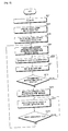
- FIG. 2 is a flowchart illustrating a procedure of a battery charging control method of an electric vehicle according to an embodiment of the present invention.
- the plug unit 150 is connected to the external power source 170 to transmit the plug-in signal to the charger controller 144.
- the driven charger controller 144 transmits a wake up signal to the charger power unit 142 and the vehicle controller 130 (S205).
- the vehicle controller 130 is received from the charger controller 144.
- the wake up signal is transmitted to the battery manager.
- the battery manager 190 receiving the driving signal transmits a BMS Ready signal indicating that the charging condition is satisfied to the vehicle controller 130.
- the vehicle controller 130 receiving the driving signal from the battery manager 190 transmits a BMS ready signal to the charger controller 144.
- the charging condition refers to a case in which the state of charge (SOC) of the high voltage battery 110 is less than or equal to the third reference value.
- the vehicle control unit 130 receiving the BMS Ready signal sends a relay drive signal to the power relay unit 120 to connect the charger power unit 142 and the high voltage battery 110.
- the charger power unit 142 converts the external AC power source 170 and transmits it to the high voltage battery 110 to charge the high voltage battery 110 by a predetermined condition. (S209)
- the voltage detector 160 detects the state of charge (SOC) of the high voltage battery 110, and the battery manager 190 continuously sends information about the state of charge to the charger controller 144. S211)
- the charger controller 144 determines whether the state of charge SOC has reached a predetermined third reference value. (S213)
- the charging mode is specifically converted from the current schedule mode to the voltage schedule mode, gradually charging Complete the step (S215).
- the charger control unit 144 if the plug is plugged into the outlet without driving the car for more than one hour at 93% or more afterwards Enters the Long Term Storage Mode (S217).
- the charger control unit 144 detects the low-voltage state of the high-voltage battery 110 After going through the preparation mode, the state of charge (SOC) is less than 95%, and performs the charging mode again (S219).
- the voltage detector 160 monitors the state of charge (SOC) of the high voltage battery again.
- FIG. 3 is a flowchart illustrating a charging control process of a battery according to an exemplary embodiment of the present invention.
- the converter When the plug-in signal is off, the converter is in sleep mode with no power supplied.
- the driven charger controller 144 transmits a wake up signal to the charger power unit 142 and the vehicle controller 130.
- the vehicle controller 130 transmits a wake up signal to the battery manager 190.
- the battery manager 190 receiving the driving signal transmits a BMS Ready signal indicating that the charging condition is satisfied to the vehicle controller 130.
- the vehicle controller 130 receiving the driving signal from the battery manager 190 transmits a BMS ready signal to the charger controller 144.
- the charger controller 144 performs a preparation mode in a state of preparing for charging.
- the charging condition refers to a case in which the state of charge (SOC) of the high voltage battery 110 is less than or equal to the third reference value.
- the vehicle control unit 130 receiving the BMS Ready signal sends a relay drive signal to the power relay unit 120 to connect the charger power unit 142 and the high voltage battery 110.
- the charger power unit 142 converts the external AC power source 170 and transmits the high voltage battery 110 to charge the high voltage battery 110 by a predetermined condition.
- the voltage detector 160 detects the state of charge (SOC) of the high voltage battery 110, and the battery manager 190 continuously sends information about the state of charge to the charger controller 144.
- SOC state of charge
- the charger controller 144 determines whether the state of charge SOC has reached a predetermined third reference value.
- the charger control unit 144 if the plug is plugged into the outlet without driving the car for more than one hour at 93% or more afterwards Performs a Long Term Storage Mode.
- the reference value may be changed from 95% or less of the state of charge (SOC), 90% or less of the state of charge (SOC), which is a charging condition, to prevent unnecessary recharging.
- the charger controller 144 of the high voltage battery 110 is reduced.
- the low voltage state is detected, and after the preparation mode, the charging state SOC is 93% or less, and thus the charging mode is performed again.
- the voltage detector 160 monitors the state of charge (SOC) of the high voltage battery again.
Abstract
The present invention relates to an electric vehicle and a charging control method for a battery thereof. An electric vehicle having a high-voltage battery which supplies driving power to a plurality of electric field loads comprises: a charger which is connected with an external power source to charge the high-voltage battery; a vehicle control module (VCM) which controls connection between the charger and the high-voltage battery; a battery management system (BMS)manages the state of the high-voltage battery according to the charging of the high-voltage battery or the supply of operating power from the high-voltage battery; and a voltage detection unit which detects and reports the charged state of the high-voltage battery to the battery management system, wherein the charger comprises a charger control unit, which controls to perform a power saving mode to minimize power consumption by interrupting the transmission of a driving signal for driving of the vehicle control module and battery management system when the charging of the high-voltage battery has been completed. Accordingly, even though the electric vehicle is left as it is after having been fully charged, the high-voltage is automatically charged, which makes it possible to stably operate the electric vehicle system.
Description
본 발명은 전기자동차 및 그 배터리의 충전제어방법에 관한 것으로서, 더욱 상세하게는 고압배터리의 충전이 완료된 이후, 고압배터리의 방전을 막고, 방전된 경우, 재충전하여 고압배터리의 상태를 최적으로 유지할 수 있는 전기자동차 및 전기자동차 배터리의 충전제어방법에 관한 것이다.The present invention relates to an electric vehicle and a charging control method for a battery thereof, and more particularly, after the charging of the high voltage battery is completed, the discharge of the high voltage battery is prevented, and when discharged, the state of the high voltage battery can be optimally maintained by recharging. The present invention relates to an electric vehicle and an electric vehicle battery charging control method.
전기자동차는 장래의 자동차 공해 및 에너지 문제를 해결할 수 있는 가장 가능성 높은 대안이라는 점에서 연구가 활발하게 진행되고 있다.Electric vehicles are being actively researched in that they are the most likely alternatives to solve future automobile pollution and energy problems.
전기자동차(Electric vehicle; EV)는 주로 배터리의 전원을 이용하여 AC 또는 DC 모터를 구동하여 동력을 얻는 자동차로서, 크게 배터리전용 전기자동차와 하이브리드 전기자동차로 분류되며, 배터리전용 전기자동차는 배터리의 전원을 이용하여 모터를 구동하고 전원이 다 소모되면 재충전하고, 하이브리드 전기자동차는 엔진을 가동하여 전기발전을 하여 배터리에 충전을 하고 이 전기를 이용하여 전기모터를 구동하여 차를 움직이게 할 수 있다. Electric vehicles (EVs) are mainly vehicles powered by AC or DC motors using battery power, and are classified into battery-only electric vehicles and hybrid electric vehicles. Using a motor to drive and recharging when the power is exhausted, the hybrid electric vehicle can run the engine to generate electricity to charge the battery and drive the electric motor using this electricity to move the car.
또한, 하이브리드 전기자동차는 직렬 방식과 병렬 방식으로 분류될 수 있으며, 직렬 방식은 엔진에서 출력되는 기계적 에너지는 발전기를 통하여 전기적 에너지로 바뀌고 이 전기적 에너지가 배터리나 모터로 공급되어 차량은 항상 모터로 구동되는 자동차로 기존의 전기자동차에 주행거리의 증대를 위하여 엔진과 발전기를 추가시킨 개념이고, 병렬 방식은 배터리 전원으로도 차를 움직이게 할 수 있고 엔진(가솔린 또는 디젤)만으로도 차량을 구동시키는 두가지 동력원을 사용하고 주행조건에 따라 병렬 방식은 엔진과 모터가 동시에 차량을 구동할 수도 있다. In addition, hybrid electric vehicles can be classified into a series and a parallel method, in which the mechanical energy output from the engine is converted into electrical energy through a generator, and the electrical energy is supplied to a battery or a motor so that the vehicle is always driven by a motor. It is a concept of adding an engine and a generator to increase the mileage of an existing electric vehicle, and the parallel method allows the vehicle to be driven by battery power and uses two power sources to drive the vehicle only by the engine (gasoline or diesel). Depending on the driving conditions and the parallel method, the engine and the motor may drive the vehicle at the same time.
또한, 최근 모터/제어기술도 점점 발달하여 고출력, 소형이면서 효율이 높은 시스템이 개발되고 있다. DC모터를 AC모터로 변환함에 따라 출력과 EV의 동력성능(가속성능, 최고속도)이 크게 향상되어 가솔린차에 비하여 손색없는 수준에 도달하였다. 고출력화를 추진하면서 고회전함에 따라 모터가 경량소형화되어 탑재중량이나 용적도 크게 감소하였다. In addition, the motor / control technology has also been developed recently, a high power, small size and high efficiency system has been developed. As the DC motor is converted to an AC motor, the output and EV power performance (acceleration performance, top speed) are greatly improved, reaching a level comparable to that of gasoline cars. As the motor rotates with high output, the motor becomes light and compact, and the payload and volume are greatly reduced.
일반적인 전기자동차용 배터리 충전장치는 외부 전원으로부터 에너지를 공급받아 고전압의 배터리(battery)에 에너지를 충전하였다가, 배터리에 저장되어 있던 저장 에너지를 사용하여 차량을 구동하게 된다. 외부전원에 플러그를 꽂아 충전하는 경우, 플러그를 꽂은 상태에서 충전이 완료된 이후, 전기자동차 내부의 전장 부하등에서 전력이 소모되어, 충전 후 오랜기간이 지나게 되면, 완충되었던 배터리가 플러그가 콘센트에 연결되어있는 상태임에도 자연방전된다. In general, a battery charger for an electric vehicle receives energy from an external power source and charges a high voltage battery, and drives the vehicle using stored energy stored in the battery. When charging by plugging in an external power source, after charging is completed while the plug is plugged in, electric power is consumed by the electric load inside the electric vehicle, and after a long time after charging, the charged battery is connected to an outlet. Discharges spontaneously even though it is.
또한, 플러그가 콘센트에 연결이 되어있는 경우, 충전이 완료된 이후에도,전기자동차의 충전기, 제어부, 릴레이 등이 계속 통전하게 되어 불필요한 소비전력을 소모하는 문제점이 있었다.In addition, when the plug is connected to the outlet, even after the charging is completed, the charger, the control unit, the relay, etc. of the electric vehicle continues to energize, there was a problem of consuming unnecessary power consumption.
본 발명의 기술적 과제는, 콘센트에 꽂아 놓은 상태에서, 일정시간이 지나, 고압배터리의 전원이 방전되는 것을 막고, 방전이 된 경우 재충전할 수 있는 전기자동차 및 그 배터리의 충전제어방법을 제공하는 데 그 목적이 있다.SUMMARY OF THE INVENTION The present invention provides an electric vehicle and a charging control method for the battery which can be recharged after being discharged in a state of being plugged into an outlet and preventing a power supply of a high voltage battery from being discharged. The purpose is.
상술한 과제를 해결하기 위한 본 발명의 실시예에 따른 전기자동차는,An electric vehicle according to an embodiment of the present invention for solving the above problems,
전기자동차를 구동하는 고압배터리와, 외부전원과 연결되어 고압배터리를 충전하는 충전기와, 충전기와 고압배터리의 연결을 제어하는 차량제어부(VCM: vehicle Control Module)와, 고압배터리의 충전 또는 고압배터리로부터의 동작전원의 공급에 따른 상기 고압배터리의 상태를 관리하는 배터리관리부(BMS:Battery Management System)와 고압배터리의 충전상태를 검출하여 배터리관리부에 전송하는 전압검출부를 포함하며, 충전기는, 고압배터리의 충전이 완료되면, 차량제어부와 배터리관리부를 가동시키는 가동신호의 전송을 중단하여 전력소모를 최소화하는 절전모드를 수행하도록 제어하는 충전기 제어부를 포함한다.From a high voltage battery for driving an electric vehicle, a charger for charging a high voltage battery connected to an external power source, a vehicle control module (VCM) for controlling a connection between a charger and a high voltage battery, and a high voltage battery for charging or The battery management unit (BMS: Battery Management System) for managing the state of the high-voltage battery in accordance with the supply of the operating power of the voltage detection unit for detecting the charge state of the high-voltage battery and transmits to the battery management unit, the charger, When the charging is completed, the charger control unit for controlling to perform a power saving mode to minimize the power consumption by stopping the transmission of the operation signal for operating the vehicle control unit and the battery management unit.
또한, 상술한 과제를 해결하기 위한 본 발명의 일실시예에 따른 전기자동차 배터리의 충전제어방법은, 고압배터리를 충전하는 충전모드를 수행하는 단계와, 충전이 완료된 후, 상기 고압배터리의 전력소비를 최소화하는 절전모드로 진입하는 단계를 포함한다.In addition, the charging control method for an electric vehicle battery according to an embodiment of the present invention for solving the above problems, the step of performing a charging mode for charging a high-voltage battery, after the charge is completed, the power consumption of the high-voltage battery Entering a power saving mode to minimize the.
본 발명의 실시예에 따르면, 콘센트와 전기자동차를 연결하여, 충전하고, 충전이 완료된 경우, 이후에 배터리가 방전되면, 자동으로 재충전함으로써, 충전하고 오랫동안 방치해두어도, 완전충전상태로 운행을 준비하고 있어 바로 사용할 수 있는 장점이 있다.According to an embodiment of the present invention, the outlet is connected to an electric vehicle, charged, and when the charging is completed, if the battery is discharged afterwards, the battery is automatically recharged, even if it is charged and left for a long time, and prepares to operate in a fully charged state. There is an advantage that can be used immediately.
전기자동차를 콘센트에 연결하여 충전하고 충전이 완료된 이후에는, 배터리의 전압을 검출하는 부분을 제외한 전체 시스템의 전원을 차단하므로, 전력의 소모를 최소화하여, 불필요한 소비전력의 소모를 줄일 수 있다. 방전되는 에너지양을 줄임으로써 에너지 효율을 높일 수 있는 장점이 있다.After the electric vehicle is connected to the outlet and charged, and after the charging is completed, the power of the entire system is cut off except for the part of detecting the voltage of the battery, thereby minimizing the power consumption, thereby reducing unnecessary power consumption. There is an advantage to increase the energy efficiency by reducing the amount of energy discharged.
장기간 보관하더라도, 충전시스템에서 고압배터리의 상태를 감시하여, 자동으로 재충전을 시도함에 따라, 방치시간과 무관하게 최적의 충전상태를 유지할 수 있으므로, 임의의 시점에 고압배터리가 완충된 상태로 전기자동차를 가동할 수 있는 장점이 있다.Even if it is stored for a long time, the charging system monitors the state of the high-voltage battery and attempts to recharge automatically, so that the optimum state of charge can be maintained regardless of the idle time. There is an advantage to operate.
도 1은, 본 발명의 일 실시예에 따른 전기자동차의 내부 구성을 개략적으로 도시한 블록도(Block Diagram)이다.1 is a block diagram schematically showing an internal configuration of an electric vehicle according to an embodiment of the present invention.
도 2는 본 발명의 일 실시예에 따른 고압배터리의 충전제어방법을 개략적으로 도시한 순서도이다.2 is a flowchart schematically illustrating a charging control method of a high voltage battery according to an exemplary embodiment of the present invention.
도 3은 본 발명의 일 실시예에 따른 고압배터리의 충전제어방법을 개략적으로 도시한 흐름도이다.3 is a flowchart schematically illustrating a charging control method of a high voltage battery according to an exemplary embodiment of the present invention.
이하, 본 발명의 실시예를 첨부된 도 1 내지 도 3을 참조하여 상세히 설명한다.Hereinafter, embodiments of the present invention will be described in detail with reference to FIGS. 1 to 3.
이하의 설명에서 사용되는 구성요소에 대한 접미사 "모듈" 및 "부"는 단순히 본 명세서 작성의 용이함만이 고려되어 부여되는 것으로서, 그 자체로 특별히 중요한 의미 또는 역할을 부여하는 것은 아니다. 따라서, 상기 "모듈" 및 "부"는 서로 혼용되어 사용될 수도 있다.The suffixes "module" and "unit" for components used in the following description are merely given in consideration of ease of preparation of the present specification, and do not impart any particular meaning or role by themselves. Therefore, the "module" and "unit" may be used interchangeably.
도 1은 전기자동차의 구성요소를 도시한 블록 구성도(block diagram)이다. 1 is a block diagram illustrating components of an electric vehicle.
도 1의 블록 구성도를 참조하여 본 발명의 일실시예에 따른 전기자동차를 기능에 따른 구성요소 관점에서 살펴보면 다음과 같다.Referring to the block diagram of FIG. 1, the electric vehicle according to an embodiment of the present invention will be described in terms of components according to functions.
본 전기자동차는 고압배터리(110), 전력릴레이부(120), 차량제어부(VCM: Vehicle Control Module)(130), 충전기(140), 보조배터리(150), 전압검출부(160), 인터페이스부(170), 전장 부하(180), 배터리관리부(190)를 포함할 수 있다.The electric vehicle includes a high voltage battery 110, a power relay unit 120, a vehicle control module (VCM) 130, a charger 140, an auxiliary battery 150, a voltage detector 160, an interface unit ( 170, the electric load 180, and a battery manager 190.
이와 같은 구성요소들은 실제 응용에서 구현될 때 필요에 따라 2 이상의 구성요소가 하나의 구성요소로 합쳐지거나, 혹은 하나의 구성요소가 2 이상의 구성요소로 세분되어 구성될 수 있다.Such components may be configured by combining two or more components into one component, or by dividing one or more components into two or more components as necessary when implemented in an actual application.
고압배터리(110)는, 복수의 배터리로 구성되며, 고전압의 전기에너지를 저장한다. 고압배터리(110)는, 전기자동차의 운행에 필요한 에너지 혹은 전장 부하를 가동시키는데에 필요한 에너지를 공급하는 주 공급원으로, 소정의 충전소, 차량 충전설비 또는 가정에서 외부로부터 전원을 공급받아 충전한다. The high voltage battery 110 is composed of a plurality of batteries, and stores electrical energy of high voltage. The high voltage battery 110 is a main supply source for supplying energy required for driving an electric vehicle or energy for operating an electric load, and is charged with power from a predetermined charging station, a vehicle charging facility, or a home.
고압배터리(110)는 전력릴레이부(120)를 사이에 두고, 충전기(140)의 충전기 파워부(142)와 연결되어, 에너지를 충전기 파워부(142)로부터 공급받는다. The high voltage battery 110 is connected to the charger power unit 142 of the charger 140 with the power relay unit 120 interposed therebetween, and receives energy from the charger power unit 142.
전압검출부(160)는, 고압배터리(110)의 출력전압의 크기를 검출한다.The voltage detector 160 detects the magnitude of the output voltage of the high voltage battery 110.
본 발명의 일실시예에 따르면, 전압검출부(160)에서 검출한 고압배터리의 출력전압이 제 2기준값 혹은 제 3기준값보다 낮은 경우, 충전기 제어부(144)는, 고압배터리를 충전, 혹은 재충전할 수 있다. According to an embodiment of the present invention, when the output voltage of the high voltage battery detected by the voltage detector 160 is lower than the second reference value or the third reference value, the charger controller 144 may charge or recharge the high voltage battery. have.
예를 들어, 전기자동차의 기본 충전의 경우를 먼저 보면, 전압검출부(160)는 고압배터리(110)의 출력전압의 크기를 검출하여, 충전상태(SOC: State Of Charge)를 체크한다. 만약에 일 예로, 충전기 제어부(144)는, 충전상태(SOC)가 95%이하라면, 고압배터리(110)를 충전하는 충전모드를 수행하도록 제어한다. 기본적인 전기자동차의 충전조건을 제 3기준값이라고 한다.For example, in the case of basic charging of an electric vehicle, the voltage detector 160 detects the magnitude of the output voltage of the high voltage battery 110 and checks the state of charge (SOC). If as an example, the charger controller 144, if the state of charge (SOC) is less than 95%, controls to perform the charging mode for charging the high-voltage battery (110). The charging condition of a basic electric vehicle is called a third reference value.
또한, 예를 들어, 전압검출부(160)에서 검출한 충전상태(SOC)가 95%이하여서 충전기 제어부(144)의 제어에 따라 충전을 하고, 충전이 완료되어 종료된 이후, 전압검출부(160)에서 고압배터리(110)의 출력전압의 크기를 검출하여, 충전상태(SOC)를 체크한다. 만약에 일 예로, 충전상태(SOC)가 93%이상으로 1시간이상 지속된다면, 충전기 제어부는(144) 전력소비를 최소화 시키는 절전모드(Long Term Storage Mode)를 수행하도록 제어한다. 절전모드로 진입하기 위한 조건을 제 1기준값이라고 정의한다. Further, for example, the state of charge (SOC) detected by the voltage detector 160 is 95% or less, so that charging is performed under the control of the charger controller 144, and after the charging is completed, the voltage detector 160 is completed. Detects the magnitude of the output voltage of the high-voltage battery 110, and checks the state of charge (SOC). If, for example, if the state of charge (SOC) lasts more than one hour to 93% or more, the charger controller 144 controls to perform a long term storage mode to minimize power consumption. The condition for entering the power saving mode is defined as a first reference value.
또한 전압검출부(160)는 절전모드에서 고압배터리(110)의 출력전압의 크기를 검출하여, 충전상태(SOC)를 체크한다. 만약에 일 예로, 충전상태(SOC)가 90%이하로 줄어들게 된다면, 충전기 제어부(144)는, 다시 충전을 대기하는 준비모드로 진입하도록 제어한다. 이 준비모드로 진입하기 위한 조건을 제 2기준값이라고 정의한다. In addition, the voltage detector 160 detects the magnitude of the output voltage of the high voltage battery 110 in the power saving mode and checks the state of charge (SOC). If, for example, if the state of charge (SOC) is reduced to less than 90%, the charger controller 144 controls to enter the ready mode to wait for charging again. The condition for entering this ready mode is defined as a second reference value.
제 2기준값이 제 1기준값보다 낮다면, 절전모드(Long Term Storage Mode)에서 준비모드(Ready Mode)로 복귀한 후, 곧바로 충전모드(Charging Mode)로 이동하여, 고압배터리(110)가 충전된다. If the second reference value is lower than the first reference value, after returning to the ready mode from the Long Term Storage Mode, the high voltage battery 110 is charged immediately after moving to the charging mode. .
전력릴레이부(120)는, 스위칭 소자로 구성된다. 본 실시예에서는, 고압배터리(110)와 충전기(140)의 충전기 파워부(142)를 연결하도록 하는 릴레이로 구성되나, 이에 한정하지 않고 동일한 기능을 수행하는 반도체 회로나 바이메탈 스위치로 구성될 수 있다.The power relay unit 120 is composed of a switching element. In the present embodiment, the high voltage battery 110 and the relay configured to connect the charger power unit 142 of the charger 140, but is not limited to this may be composed of a semiconductor circuit or a bimetal switch to perform the same function. .
전력릴레이부(120)는, 차량제어부(VCM: Vehicle Control Module)(130)의 제어를 받아 동작한다. 전력릴레이부(120)는 차량제어부(VCM: Vehicle Control Module)(130)으로부터 인가되는 신호에 따라, 복수의 릴레이를 스위칭한다. The power relay unit 120 operates under the control of a vehicle control module (VCM) 130. The power relay unit 120 switches a plurality of relays according to a signal applied from the vehicle control module (VCM) 130.
전력릴레이부(120)는, 충전기 파워부(142)와 고압배터리(110)를 연결하여, 외부전원(170)으로부터 플러그부(150)를 통해 충전기 파워부(142)로 공급된 에너지를 고압배터리(110)로 보내어 고압배터리(110)를 충전할 수 있다. The power relay unit 120 connects the charger power unit 142 and the high voltage battery 110 to convert the energy supplied from the external power supply 170 into the charger power unit 142 through the plug unit 150 to the high voltage battery. It can be sent to 110 to charge the high-voltage battery (110).
차량제어부(VCM: Vehicle Control Module)(130)는, 전력릴레이부(120)의 on/off를 제어하고, 충전기(140)의 충전기 제어부(144)와 상호 신호를 주고 받으면서, 충전기 파워부(142)의 동작을 제어할 수 있다. The vehicle control module (VCM) 130 controls the on / off of the power relay unit 120 and exchanges a signal with the charger control unit 144 of the charger 140, and the charger power unit 142. ) Can be controlled.
차량제어부(VCM: Vehicle Control Module)(130)는, 배터리관리부(190)를 통해 고압배터리(110)를 관리할 수 있다.The vehicle control module (VCM) 130 may manage the high voltage battery 110 through the battery manager 190.
또한 차량제어부(VCM: Vehicle Control Module)(130)는, 충전이 종료되면, 충전기 제어부(144)에서 보내는 충전종료신호(EOC: End of Charge)를 수신한다. 충전종료신호를 받은 차량제어부(VCM: Vehicle Control Module)(130)는, 전력릴레이부(120) 구동신호를 off하여, 충전기(140)와 고압배터리(110)를 분리할 수 있다. Also, the vehicle control module (VCM) 130 receives an end of charge (EOC) signal sent from the charger controller 144 when the charging is completed. The vehicle control module (VCM) 130 receiving the charging end signal may turn off the power relay 120 driving signal to separate the charger 140 from the high voltage battery 110.
차량제어부(VCM: Vehicle Control Module)(130)는, 충전기 제어부(144) 혹은 배터리관리부(190)와 신호를 주고 받는 경우, CAN통신 버스를 이용할 수 있으나, 이는 일 예일 뿐 이에 한정하지 않는다. The vehicle control module (VCM) 130 may use a CAN communication bus when exchanging a signal with the charger control unit 144 or the battery management unit 190, but this is only an example and the present disclosure is not limited thereto.
충전기(140)는, 충전기 파워부(142)와 충전기 제어부(144)를 포함할 수 있다. 충전기(140)는 외부 교류전원을 공급받아 고압배터리(110)를 충전하게 된다. The charger 140 may include a charger power unit 142 and a charger controller 144. The charger 140 receives an external AC power to charge the high voltage battery 110.
충전기 파워부(142)는, 전력릴레이부(120)를 사이에 두고, 고압배터리(110)와 연결된다. 일 측은 플러그부(150)에 연결되어 있고, 플러그부(150)는 콘센트와 연결되어 있다. 전력릴레이부(120)가 on상태인 경우, 플러그부(150)로 부터 받은 외부전원을 고압배터리(110)에 공급하여 고압배터리(110)를 충전할 수 있다.The charger power unit 142 is connected to the high voltage battery 110 with the power relay unit 120 interposed therebetween. One side is connected to the plug unit 150, the plug unit 150 is connected to the outlet. When the power relay unit 120 is in the on state, the high voltage battery 110 may be charged by supplying the external power received from the plug unit 150 to the high voltage battery 110.
충전기 제어부(144)는, 고압배터리(110)의 충전이 완료되면, Can버스 통신을 통해 충전종료신호(EOC: End Of Charging)를 송신한다. 또한, 가동신호(wake up신호)의 전송을 중단하여 충전준비모드(Ready Mode)를 수행한다. When charging of the high voltage battery 110 is completed, the charger controller 144 transmits an end-of-charging signal (EOC) through CanBus communication. In addition, the transmission of the wake up signal is stopped to perform a ready mode.
충전기 제어부(144)는, 충전준비모드(Ready Mode) 수행 중에 전압검출부(160)에서 검출한 충전상태(SOC)가 제 1기준값 이상으로 소정시간이 경과되면, 절전모드(Long Term Storage Mode)를 수행한다. The charger controller 144 may enter the long term storage mode when a predetermined time elapses when the state of charge SOC detected by the voltage detector 160 is greater than or equal to the first reference value during the execution of the ready mode. To perform.
즉, 충전기 제어부(144)는 특정값 이상으로 어느 정도 시간이 경과하면, 전압검출부(160)로만 전원이 공급되도록 하여, 고압배터리(110)의 대기전력소모를 감소시킴에 따라 고압배터리(110)의 방전속도를 늦추기 위한, 절전모드(Long Term Storage Mode)를 수행한다. 전압검출부(160)는 절전모드(Long Term Storage Mode)에서 전압검출을 하여 충전기 제어부(144)로 이를 전송한다. That is, when a certain time elapses above a specific value, the charger controller 144 supplies power only to the voltage detector 160, thereby reducing standby power consumption of the high voltage battery 110, thereby increasing the high voltage battery 110. In order to slow down the discharge rate of the battery, a Long Term Storage Mode is performed. The voltage detector 160 detects a voltage in a long term storage mode and transmits the detected voltage to the charger controller 144.
예를 들어, 절전모드(Long Term Storage Mode)에서 고압배터리(110)의 충전상태(SOC)가 제 2기준값미만이라면, 충전기 제어부(144)는 전압검출부(160)에서 보낸 저전압신호를 수신하여, 충전을 준비하는 충전준비모드(Ready Mode)를 재수행한다. For example, if the state of charge (SOC) of the high-voltage battery 110 is less than the second reference value in the Long Term Storage Mode, the charger controller 144 receives the low voltage signal sent from the voltage detector 160, Rerun the Ready mode to prepare for charging.
제 2기준값은, 전기자동차의 설계자가 임의로 정할 수 있다. 후술할 도 3의 흐름도에서 보면, 일예로 제 2기준값은 충전상태(SOC) 90%미만이라고 도시하였으나, 이는 일 예일뿐, 설계자에 따라 구체적인 수치의 조정이 가능하다. The second reference value can be arbitrarily determined by the designer of the electric vehicle. In the flowchart of FIG. 3 to be described later, for example, the second reference value is shown to be less than 90% of a state of charge (SOC), but this is only an example, and specific values may be adjusted according to a designer.
충전기 제어부(144)는, 충전상태가 제 3기준값 미만이면, 외부전원(170)과 고압배터리(110)가 연결되도록 상기 차량제어부(130)에 가동신호(wake-up)를 송신하여, 전력릴레이부(120)를 닫아 충전기(140)와 고압배터리(110)를 연결하여 충전하는 충전모드로 진입하도록 제어한다.The charger controller 144 transmits a wake-up signal to the vehicle controller 130 so that the external power source 170 and the high voltage battery 110 are connected when the state of charge is less than the third reference value. By closing the unit 120 controls the charger 140 and the high-voltage battery 110 to enter the charging mode to charge.
제 3기준값은, 전기자동차 설계자가 임의로 정할 수 있다. 후술할 도 3의 흐름도의 경우, 충전상태(SOC) 95%이하인 경우, 충전준비모드에서 충전모드로 진입하게 된다. 이는 일 예일뿐, 충전모드로의 진입 조건은 설계자에 따라 조정이 가능하다.The third reference value can be arbitrarily determined by the electric vehicle designer. In the flowchart of FIG. 3 to be described later, when the state of charge (SOC) is 95% or less, the charging mode enters the charging mode. This is just an example, the conditions for entering the charging mode can be adjusted according to the designer.
충전기 제어부(144)는, 충전모드 수행 중에, 고압배터리 충전상태(SOC)가 제 3기준값 이상이면, 충전모드를 변환한다.The charger controller 144 converts the charging mode when the high-voltage battery state of charge SOC is equal to or greater than the third reference value during the charging mode.
구체적으로, 충전모드의 변환은, 전류값을 고정시키고, 전압값을 증가시키면서 충전하는 전류일정모드(CC Mode)에서 전압값을 고정시키고, 전류값을 서서히 감소시키면서 충전을 종료하는 전압일정모드(CV Mode)로의 변환이다.Specifically, the conversion of the charging mode, the voltage constant mode in which the current value is fixed and the voltage value is fixed in the current constant mode (CC Mode) for charging while increasing the voltage value, and the charging is terminated while gradually decreasing the current value. CV Mode).
즉, 제 3기준값이하일 경우, 충전모드를 수행하다가, 충전이 진행되어 다시 충전상태(SOC)가 제 3기준값 이상으로 될 경우, 충전을 서서히 완료하기 위해, 전압값을 고정시키고, 전류값을 서서히 감소시키는 충전모드로 변환하는 것이다.That is, when the third reference value is less than, while performing the charging mode, when charging is progressed again when the state of charge (SOC) is more than the third reference value, in order to complete the charging gradually, the voltage value is fixed and the current value is gradually To reduce charging mode.
충전기 제어부(144)는, 전압일정모드(CV Mode)가 종료되면, 충전종료신호(EOC: End Of Charge)를 차량제어부(130)으로 보낸다.The charger controller 144 transmits an end-of-charge signal (EOC) to the vehicle controller 130 when the voltage schedule mode (CV Mode) ends.
차량제어부(130)는, 상기 충전종료신호(EOC: End Of Charge)를 받아 전력릴레이부(120)의 릴레이를 개방시켜 충전기(140)와 고압배터리(110)를 분리시킬 수 있다.The vehicle controller 130 may receive the end-of-charge signal (EOC) to open the relay of the power relay unit 120 to separate the charger 140 from the high voltage battery 110.
플러그부(150)는, 외부전원(170)과 충전기(140)를 연결할 수 있다. 플러그부(150)를 콘센트에 연결하여, 외부전원(170)이 충전기 파워부(142)로 전달된다. The plug unit 150 may connect the external power source 170 and the charger 140. By connecting the plug unit 150 to an outlet, the external power source 170 is transmitted to the charger power unit 142.
플러그부(150)는, 충전기 제어부(142)로 플러그가 콘센트에 접속이 되었다는 플러그인 신호를 충전기 제어부(144)로 전송한다. The plug unit 150 transmits a plug-in signal to the charger controller 144 that the plug is connected to the outlet by the charger controller 142.
전압검출부(160)는, 고압배터리(110)측의 전압을 검출하여, 검출된 전압치를 출력하여 검출된 전압치에 관한 정보를 배터리관리부(190)로 송신할 수 있다. The voltage detector 160 may detect the voltage at the high voltage battery 110, output the detected voltage value, and transmit information about the detected voltage value to the battery manager 190.
배터리관리부(190)는, 측정된 전압의 크기를 어떠한 소정의 기준값과 비교하여, 비교한 데이터를 충전기 제어부(144), 차량제어부(130)등으로 송신할 수 있다.The battery manager 190 may compare the magnitude of the measured voltage with a predetermined reference value and transmit the compared data to the charger controller 144, the vehicle controller 130, or the like.
외부전원(170)은, 가정용 외부전원일 수도 있고, 전기자동차 충전용 외부전원일 수도 있다. 콘센트 혹은 다른 형태의 접속단자로 플러그와 연결할 수 있다. 플러그부(150)와 연결된 외부전원(170)에서, 충전기 파워부(142)로 에너지를 공급할 수 있다.The external power source 170 may be a home external power source or an electric vehicle charging external power source. You can connect the plug to an outlet or other type of connector. In the external power source 170 connected to the plug unit 150, energy may be supplied to the charger power unit 142.
배터리 관리부(BMS: Battery management system)(190)는, 고압배터리(110)의 잔여용량, 충전 필요성 등을 판단하고, 배터리에 저장된 충전전류를 전기자동차의 각 부로 공급하는데 따른 관리를 수행할 수 있다. The battery management system (BMS) 190 may determine the remaining capacity of the high voltage battery 110, the necessity of charging, and perform management for supplying the charging current stored in the battery to each part of the electric vehicle. .
배터리 관리부(BMS: Battery management system)(190)는, 배터리를 충전하고 사용할 때, 배터리 내의 셀 간의 전압차를 고르게 유지할 수 있다. 이에 따라, 배터리가 과충전되거나 과방전되지 않도록 제어함으로써 배터리의 수명을 연장시킬 수 있다. The battery management system (BMS) 190 may maintain the voltage difference between cells in the battery evenly when charging and using the battery. Accordingly, the battery life can be extended by controlling the battery not to be overcharged or overdischarged.
또한, 배터리 관리부(BMS: Battery management system)(190)는, 전류사용에 대한 관리를 통해 차량이 장시간 주행할 수 있도록 하고, 공급되는 전류에 대한 보호 회로를 포함할 수 있다. In addition, the battery management system (BMS) 190 may allow the vehicle to travel for a long time through management of current use, and may include a protection circuit for the supplied current.
도 2는 본 발명의 일 실시예에 따른, 전기자동차의 배터리 충전제어방법의 순서를 도시한 순서도이다.2 is a flowchart illustrating a procedure of a battery charging control method of an electric vehicle according to an embodiment of the present invention.
외부전원(170)에 플러그부(150)를 연결하여, 충전기 제어부(144)로 플러그인 신호를 송신한다.(S201)The plug unit 150 is connected to the external power source 170 to transmit the plug-in signal to the charger controller 144.
외부전원(170)과 충전기(140)가 연결됨으로써, 충전기 파워부(142)에 외부의 교류전원이 인가되고, 충전기 제어부(144)가 구동된다.(S203)By connecting the external power source 170 and the charger 140, an external AC power is applied to the charger power unit 142, and the charger control unit 144 is driven (S203).
구동된 충전기 제어부(144)는, 충전기 파워부(142)와 차량제어부(130)로구동신호(wake up signal)을 전송한다.(S205) 차량제어부(130)는 충전기 제어부(144)로부터 전송받은 구동신호(wake up signal)를 배터리 관리부로 전송한다.The driven charger controller 144 transmits a wake up signal to the charger power unit 142 and the vehicle controller 130 (S205). The vehicle controller 130 is received from the charger controller 144. The wake up signal is transmitted to the battery manager.
구동신호를 받은 배터리 관리부(190)는 차량제어부(130)로 충전조건을 만족했다는 충전준비신호(BMS Ready signal)을 송신한다. 배터리 관리부(190)로부터 구동신호를 받은 차량제어부(130)는 충전기 제어부(144)로 충전준비신호(BMS Ready signal)를 송신한다. (S207) The battery manager 190 receiving the driving signal transmits a BMS Ready signal indicating that the charging condition is satisfied to the vehicle controller 130. The vehicle controller 130 receiving the driving signal from the battery manager 190 transmits a BMS ready signal to the charger controller 144. (S207)
충전조건은 현재 고압배터리(110)의 충전상태(SOC)가 제 3기준값 이하인 경우를 말한다. 충전준비신호(BMS Ready signal)를 수신한 차량제어부(130)는, 전력릴레이부(120)로 릴레이구동신호를 보내어, 충전기 파워부(142)와, 고압배터리(110)를 연결한다.The charging condition refers to a case in which the state of charge (SOC) of the high voltage battery 110 is less than or equal to the third reference value. The vehicle control unit 130 receiving the BMS Ready signal sends a relay drive signal to the power relay unit 120 to connect the charger power unit 142 and the high voltage battery 110.
충전기파워부(142)는 외부의 교류전원(170)을 변환하여 고압배터리(110)로 전송하여 정해진 조건만큼 고압배터리(110)를 충전한다. (S209)The charger power unit 142 converts the external AC power source 170 and transmits it to the high voltage battery 110 to charge the high voltage battery 110 by a predetermined condition. (S209)
충전이 진행중 일 때, 전압검출부(160)는 고압배터리(110)의 충전상태(SOC)를 검출하여, 배터리 관리부(190)는, 계속 충전기 제어부(144)로 충전상태에 관한 정보를 보낸다.(S211)When charging is in progress, the voltage detector 160 detects the state of charge (SOC) of the high voltage battery 110, and the battery manager 190 continuously sends information about the state of charge to the charger controller 144. S211)
충전기 제어부(144)는, 충전상태(SOC)가 정해진 제 3기준값에 도달한 것인지 여부를 판단한다. (S213)The charger controller 144 determines whether the state of charge SOC has reached a predetermined third reference value. (S213)
본 발명의 일예로 도시한 순서도를 참고하면, 충전상태(SOC)가 95%이상인지 여부를 판단하여, 95%이상인 경우, 충전모드를 구체적으로 전류일정모드에서 전압일정모드로 변환하여, 서서히 충전을 완료한다.(S215)Referring to the flowchart shown as an example of the present invention, it is determined whether the state of charge (SOC) is more than 95%, and if more than 95%, the charging mode is specifically converted from the current schedule mode to the voltage schedule mode, gradually charging Complete the step (S215).
충전상태(SOC)가 아직 95%미만이라면, 진행중이던 충전을 계속하고, 다시 충전 중의 충전상태(SOC)를 검출한다. If the state of charge SOC is still less than 95%, the ongoing charge is continued, and the state of charge SOC in charge is detected again.
충전상태(SOC)가 95%이상이 되어, 충전을 완료한 경우, 이후에 93%이상으로 1시간이상, 자동차를 운전하지 않고, 콘센트에 플러그를 꽂은 상태로 있는 경우라면, 충전기 제어부(144)는 절전모드(Long Term Storage Mode)로 진입한다.(S217) If the state of charge (SOC) is more than 95%, and the charge is completed, the charger control unit 144 if the plug is plugged into the outlet without driving the car for more than one hour at 93% or more afterwards Enters the Long Term Storage Mode (S217).
절전모드(Long Term Storage Mode)에서는 일예로 기존에 충전조건인 충전상태(SOC) 95%이하에서, 충전상태(SOC) 90%이하로 기준값을 변경하여, 불필요한 재충전을 방지할 수 있다.(S219) 고압배터리(110)의 자연방전에 따라, 고압배터리(110)의 충전상태(SOC)가 90%미만으로 감소하게 되면, 충전기 제어부(144)는, 고압배터리(110)의 저전압상태를 감지하여, 준비모드를 거쳐, 충전상태(SOC)가 95%이하이므로, 다시 충전모드를 수행한다.(S219) In Long Term Storage Mode, for example, it is possible to prevent unnecessary recharging by changing the reference value to 95% or less of the state of charge (SOC), which is the existing charging condition, and 90% or less of the state of charge (SOC). According to the natural discharge of the high-voltage battery 110, when the state of charge (SOC) of the high-voltage battery 110 is reduced to less than 90%, the charger control unit 144 detects the low-voltage state of the high-voltage battery 110 After going through the preparation mode, the state of charge (SOC) is less than 95%, and performs the charging mode again (S219).
아직 고압배터리(110)의 충전상태(SOC)가 90%이하로 감소하지 않았다면, 전압검출부(160)는 다시 고압배터리의 충전상태(SOC)를 감시한다.If the state of charge (SOC) of the high voltage battery 110 has not been reduced to 90% or less yet, the voltage detector 160 monitors the state of charge (SOC) of the high voltage battery again.
도 3은, 본 발명의 일 실시예에 따른 배터리의 충전제어과정을 도시한 흐름도이다.3 is a flowchart illustrating a charging control process of a battery according to an exemplary embodiment of the present invention.
플러그인 신호가 오프가 되면, 컨버터에 전원이 공급되지 않는 휴지상태(Sleep Mode)이다.When the plug-in signal is off, the converter is in sleep mode with no power supplied.
플러그인 신호가 온 상태가 되면, 충전기 파워부(142)에 외부의 교류전원이 인가되고, 충전기 제어부(144)가 구동된다.When the plug-in signal is turned on, an external AC power is applied to the charger power unit 142, and the charger controller 144 is driven.
구동된 충전기 제어부(144)는, 충전기 파워부(142)와 차량제어부(130)로구동신호(wake up signal)를 전송한다. 차량제어부(130)는, 배터리 관리부(190)로 구동신호(wake up signal)를 전송한다.The driven charger controller 144 transmits a wake up signal to the charger power unit 142 and the vehicle controller 130. The vehicle controller 130 transmits a wake up signal to the battery manager 190.
구동신호를 받은 배터리 관리부(190)는 차량제어부(130)로 충전조건을 만족했다는 충전준비신호(BMS Ready signal)을 송신한다. 배터리 관리부(190)로부터 구동신호를 받은 차량제어부(130)는 충전기 제어부(144)로 충전준비신호(BMS Ready signal)를 송신한다.The battery manager 190 receiving the driving signal transmits a BMS Ready signal indicating that the charging condition is satisfied to the vehicle controller 130. The vehicle controller 130 receiving the driving signal from the battery manager 190 transmits a BMS ready signal to the charger controller 144.
충전기 제어부(144)는 충전을 준비하는 상태인 준비모드를 수행한다.The charger controller 144 performs a preparation mode in a state of preparing for charging.
충전조건은 현재 고압배터리(110)의 충전상태(SOC)가 제 3기준값 이하인 경우를 말한다. 충전준비신호(BMS Ready signal)를 수신한 차량제어부(130)는, 전력릴레이부(120)로 릴레이구동신호를 보내어, 충전기 파워부(142)와, 고압배터리(110)를 연결한다. The charging condition refers to a case in which the state of charge (SOC) of the high voltage battery 110 is less than or equal to the third reference value. The vehicle control unit 130 receiving the BMS Ready signal sends a relay drive signal to the power relay unit 120 to connect the charger power unit 142 and the high voltage battery 110.
도시한 흐름도에서 고압배터리(110)의 충전상태(SOC)가 95%이하인 경우, 준비모드에서 충전모드로 진입한다. When the state of charge (SOC) of the high-voltage battery 110 is less than 95% in the illustrated flow chart, enters the charging mode in the ready mode.
충전모드에서, 충전기파워부(142)는 외부의 교류전원(170)을 변환하여 고압배터리(110)로 전송하여 정해진 조건만큼 고압배터리(110)를 충전한다. In the charging mode, the charger power unit 142 converts the external AC power source 170 and transmits the high voltage battery 110 to charge the high voltage battery 110 by a predetermined condition.
충전이 진행중 일 때, 전압검출부(160)는 고압배터리(110)의 충전상태(SOC)를 검출하여, 배터리 관리부(190)는, 계속 충전기 제어부(144)로 충전상태에 관한 정보를 보낸다.When charging is in progress, the voltage detector 160 detects the state of charge (SOC) of the high voltage battery 110, and the battery manager 190 continuously sends information about the state of charge to the charger controller 144.
충전기 제어부(144)는, 충전상태(SOC)가 정해진 제 3기준값에 도달한 것인지 여부를 판단한다. The charger controller 144 determines whether the state of charge SOC has reached a predetermined third reference value.
도 3에서 충전상태(SOC)가 95%이상이 된 경우, 전류일정모도(CC Mode)에서 전압일정모드(CV Mode)로 변환하여 충전을 완료한다. In FIG. 3, when the state of charge (SOC) becomes 95% or more, the charging is completed by converting from the current constant mode (CC Mode) to the voltage constant mode (CV Mode).
충전상태(SOC)가 95%이상이 되어, 충전을 완료한 경우, 이후에 93%이상으로 1시간이상, 자동차를 운전하지 않고, 콘센트에 플러그를 꽂은 상태로 있는 경우라면, 충전기 제어부(144)는 절전모드(Long Term Storage Mode)를 수행한다.If the state of charge (SOC) is more than 95%, and the charge is completed, the charger control unit 144 if the plug is plugged into the outlet without driving the car for more than one hour at 93% or more afterwards Performs a Long Term Storage Mode.
절전모드(Long Term Storage Mode)에서는 일예로 기존에 충전조건인 충전상태(SOC) 95%이하에서, 충전상태(SOC) 90%이하로 기준값을 변경하여, 불필요한 재충전을 방지할 수 있다.In the Long Term Storage Mode, for example, the reference value may be changed from 95% or less of the state of charge (SOC), 90% or less of the state of charge (SOC), which is a charging condition, to prevent unnecessary recharging.
전압검출부(160)에서 지속적으로 전력을 소비함에 따라, 시간이 지나면 고압배터리(110)의 충전상태(SOC)가 90%미만으로 감소하게 되면, 충전기 제어부(144)는, 고압배터리(110)의 저전압상태를 감지하여, 준비모드를 거쳐, 충전상태(SOC)가 93%이하이므로, 다시 충전모드를 수행한다. As power is continuously consumed by the voltage detector 160, when the state of charge (SOC) of the high voltage battery 110 decreases to less than 90% as time passes, the charger controller 144 of the high voltage battery 110 is reduced. The low voltage state is detected, and after the preparation mode, the charging state SOC is 93% or less, and thus the charging mode is performed again.
아직 고압배터리(110)의 충전상태(SOC)가 90%이하로 감소하지 않았다면, 전압검출부(160)는 다시 고압배터리의 충전상태(SOC)를 감시한다.If the state of charge (SOC) of the high voltage battery 110 has not been reduced to 90% or less yet, the voltage detector 160 monitors the state of charge (SOC) of the high voltage battery again.
또한, 이상에서는 본 발명의 바람직한 실시예에 대하여 도시하고 설명하였지만, 본 발명은 상술한 특정의 실시예에 한정되지 아니하며, 청구범위에서 청구하는 본 발명의 요지를 벗어남이 없이 당해 발명이 속하는 기술분야에서 통상의 지식을 가진자에 의해 다양한 변형실시가 가능한 것은 물론이고, 이러한 변형실시들은 본 발명의 기술적 사상이나 전망으로부터 개별적으로 이해되어져서는 안될 것이다.In addition, although the preferred embodiment of the present invention has been shown and described above, the present invention is not limited to the specific embodiments described above, but the technical field to which the invention belongs without departing from the spirit of the invention claimed in the claims. Of course, various modifications can be made by those skilled in the art, and these modifications should not be individually understood from the technical spirit or the prospect of the present invention.
Claims (13)
- 복수개의 전장 부하에 구동전원을 공급하는 고압배터리를 구비하는 전기자동차에 있어서,An electric vehicle having a high voltage battery for supplying driving power to a plurality of electric loads,외부전원과 연결되어 고압배터리를 충전하는 충전기;A charger connected to an external power source to charge the high voltage battery;상기 충전기와 고압배터리의 연결을 제어하는 차량제어부(VCM: vehicle Control Module);A vehicle control module (VCM) for controlling the connection of the charger and the high voltage battery;상기 고압배터리의 충전 또는 상기 고압배터리로부터의 동작전원의 공급에 따른 상기 고압배터리의 상태를 관리하는 배터리관리부(BMS:Battery Management System);A battery management unit (BMS) for managing the state of the high voltage battery according to the charging of the high voltage battery or the supply of operating power from the high voltage battery;상기 고압배터리의 충전상태를 검출하여 상기 배터리관리부에 전송하는 전압검출부;를 포함하며,And a voltage detector for detecting a charge state of the high voltage battery and transmitting the detected state to the battery manager.상기 충전기는, 상기 고압배터리의 충전이 완료되면, 상기 차량제어부와 상기 배터리관리부를 가동시키는 가동신호의 전송을 중단하여 전력소모를 최소화하는 절전모드를 수행하도록 제어하는 충전기 제어부를 포함하는 전기자동차.The charger, when the charging of the high-voltage battery is completed, the electric vehicle including a charger control unit for controlling to perform a power saving mode to minimize the power consumption by stopping the transmission of the operation signal for operating the vehicle control unit and the battery manager.
- 제 1항에 있어서,The method of claim 1,상기 충전기 제어부는,The charger control unit,상기 고압배터리의 충전이 완료되면, 상기 가동신호의 전송을 중단하여 충전준비모드를 수행하며, 상기 충전준비모드 수행중 상기 전압검출부에서 검출한 충전상태가 제 1기준값 이상으로 소정시간이 경과되면, 상기 절전모드를 수행하는 전기자동차.When the charging of the high-voltage battery is completed, the transmission of the operation signal is stopped to perform a charging preparation mode, and when the charging state detected by the voltage detector during the charging preparation mode is greater than or equal to a first reference value, a predetermined time passes. An electric vehicle performing the power saving mode.
- 제 1항에 있어서,The method of claim 1,상기 충전기 제어부는,The charger control unit,상기 절전모드 수행시, 상기 전압검출부로만 전원이 공급되도록하는 전기자동차.When the power saving mode is performed, the electric vehicle to supply power only to the voltage detector.
- 제 2항에 있어서,The method of claim 2,상기 충전기 제어부는,The charger control unit,상기 절전모드에서, 상기 고압배터리의 충전상태가 제 2기준값 미만이면, 상기 전압검출부로부터 저전압신호를 수신하여, 상기 절전모드를 해제하고 충전대기상태인 충전준비모드를 재수행하도록 제어하는 전기자동차.In the power saving mode, when the state of charge of the high-voltage battery is less than the second reference value, the electric vehicle receives a low voltage signal from the voltage detector, to release the power saving mode and control to perform the charge ready mode of the charging standby state.
- 제 1항에 있어서, The method of claim 1,상기 충전기 제어부는, 상기 충전상태가 제 3기준값 미만이면, 상기 외부전원과 고압배터리가 연결되도록 상기 차량제어부에 가동신호를 송신하여, 상기 고압배터리를 충전하는 충전모드로 진입하는 전기자동차.The charger control unit, when the state of charge is less than the third reference value, the electric vehicle to enter the charging mode for charging the high-voltage battery by transmitting an operation signal to the vehicle control unit so that the external power and the high-voltage battery is connected.
- 제 5항에 있어서,The method of claim 5,상기 충전기제어부는, The charger control unit,상기 충전모드 수행중, 상기 고압배터리 충전상태가 제 1기준값 이상이면, 전류값을 고정시키고 전압값을 증가시키면서 충전하는 전류일정모드에서, 전압값을 고정시키고 전류값을 서서히 감소시키면서 충전을 종료하는 전압일정모드로 변환하는 전기자동차.During the charging mode, when the state of charge of the high-voltage battery is greater than or equal to the first reference value, in the current schedule mode in which the current value is fixed and charged while increasing the voltage value, the charging is terminated while the voltage value is fixed and the current value is gradually decreased. Electric vehicle converts to voltage constant mode.
- 제 6항에 있어서,The method of claim 6,상기 충전기 제어부는, 상기 전압일정모드가 종료되면, 충전종료신호를 상기 차량제어부으로 보내고,The charger controller, when the voltage schedule mode ends, sends a charging end signal to the vehicle controller,상기 차량제어부는, 상기 충전종료신호를 받아 상기 전력릴레이부의 릴레이를 개방시켜 상기 충전기와 상기 고압배터리를 분리시키는 전기자동차. The vehicle control unit receives the charging end signal to open the relay of the power relay unit to separate the charger and the high-voltage battery.
- 복수개의 전장 부하에 구동전원을 공급하는 고압배터리를 구비하는 전기자동차의 배터리 충전제어방법에 있어서,In the battery charge control method of an electric vehicle having a high-voltage battery for supplying driving power to a plurality of electrical loads,상기 고압배터리를 충전하는 충전모드를 수행하는 단계; Performing a charging mode for charging the high voltage battery;상기 충전이 완료된 후, 상기 고압배터리의 전력소비를 최소화하는 절전모드로 진입하는 단계를 포함하는 전기자동차 배터리의 충전제어방법.After the charging is completed, the electric vehicle battery charging control method comprising the step of entering a power saving mode to minimize the power consumption of the high-voltage battery.
- 제 8항에 있어서,The method of claim 8,상기 충전이 완료된 후, 충전상태가 제 1기준값 이상으로 소정시간이상이 경과되면 상기 절전모드를 수행하는 전기자동차 배터리의 충전제어방법.After the charging is completed, the charge control method of the electric vehicle battery to perform the power saving mode when the state of charge exceeds a first reference value or more than a predetermined time.
- 제 8항에 있어서,The method of claim 8,상기 절전모드상태에서 상기 고압배터리의 충전상태가 다시 제 2기준값 이하가 되면, 상기 고압배터리를 재충전하는 단계;를 더 포함하는 전기자동차 배터리의 충전제어방법.And recharging the high voltage battery when the state of charge of the high voltage battery is lower than the second reference value again in the power saving mode state.
- 제 8항에 있어서,The method of claim 8,상기 고압배터리의 충전상태가 제 3기준값 미만이면, 외부전원과 상기 고압배터리를 연결하여, 상기 충전모드를 수행하는 전기자동차 배터리의 충전제어방법.When the state of charge of the high-voltage battery is less than a third reference value, the charge control method of the electric vehicle battery to perform the charging mode by connecting an external power supply and the high-voltage battery.
- 제 8항에 있어서,The method of claim 8,상기 충전모드를 수행 중, 상기 고압배터리 충전상태가 제 3기준값 이상이면, 전류값을 고정시키고 전압값을 증가시키면서 충전하는 전류일정모드에서, 전압값을 고정시키고 전류값을 서서히 감소시키면서 충전을 종료하는 전압일정모드로 변환하는 전기자동차 배터리의 충전제어방법.During the charging mode, when the state of charge of the high-voltage battery is equal to or greater than the third reference value, in the current schedule mode in which the current value is fixed and the battery is charged while increasing the voltage value, the charging is terminated while the voltage value is fixed and the current value is gradually decreased. Charging control method of an electric vehicle battery to convert to a voltage constant mode.
- 제 12항에 있어서, The method of claim 12,상기 충전모드를 변환하여 충전이 완료되면, 상기 고압배터리와 상기 외부전원을 연결하는 릴레이를 개방시켜 상기 고압배터리와 상기 외부전원을 분리시키는 단계;를 더 포함하는 전기자동차의 배터리 충전제어방법.When the charging mode is completed by changing the charging mode, opening the relay for connecting the high voltage battery and the external power to separate the high voltage battery and the external power; Battery charging control method of an electric vehicle further comprising.
Priority Applications (1)
| Application Number | Priority Date | Filing Date | Title |
|---|---|---|---|
| US13/813,906 US20130127418A1 (en) | 2010-08-02 | 2011-08-01 | Electric vehicle and charging control method for battery thereof |
Applications Claiming Priority (2)
| Application Number | Priority Date | Filing Date | Title |
|---|---|---|---|
| KR1020100074753A KR101582577B1 (en) | 2010-08-02 | 2010-08-02 | Electric vehicles and method for battery charging control thereof |
| KR10-2010-0074753 | 2010-08-02 |
Publications (2)
| Publication Number | Publication Date |
|---|---|
| WO2012018204A2 true WO2012018204A2 (en) | 2012-02-09 |
| WO2012018204A3 WO2012018204A3 (en) | 2012-05-31 |
Family
ID=45559911
Family Applications (1)
| Application Number | Title | Priority Date | Filing Date |
|---|---|---|---|
| PCT/KR2011/005643 WO2012018204A2 (en) | 2010-08-02 | 2011-08-01 | Electric vehicle and charging control method for battery thereof |
Country Status (3)
| Country | Link |
|---|---|
| US (1) | US20130127418A1 (en) |
| KR (1) | KR101582577B1 (en) |
| WO (1) | WO2012018204A2 (en) |
Cited By (5)
| Publication number | Priority date | Publication date | Assignee | Title |
|---|---|---|---|---|
| WO2015065094A1 (en) * | 2013-10-31 | 2015-05-07 | 주식회사 엘지화학 | Application module mode control device and mode control method therefor |
| CN105006820A (en) * | 2015-06-26 | 2015-10-28 | 广西电网有限责任公司电力科学研究院 | Quantitative analysis method for influence of electric energy quality on comprehensive energy consumption of power transmission line |
| EP2867975A4 (en) * | 2012-06-27 | 2016-05-11 | Byd Co Ltd | Charging system, vehicle comprising the same and method for controlling charging vehicle with the same |
| WO2019160330A1 (en) * | 2018-02-13 | 2019-08-22 | 엘지이노텍 주식회사 | Charging control device for electric vehicle |
| CN114013279A (en) * | 2020-07-17 | 2022-02-08 | 上海汽车集团股份有限公司 | Power battery discharging equipment and discharging control method |
Families Citing this family (28)
| Publication number | Priority date | Publication date | Assignee | Title |
|---|---|---|---|---|
| CN103259826B (en) * | 2012-02-20 | 2016-06-01 | 伊顿公司 | For the data transmission device between charger and electric motor car and method |
| KR102007835B1 (en) * | 2012-03-13 | 2019-08-07 | 에스케이이노베이션 주식회사 | Power supply of Battery Management System |
| KR101458130B1 (en) * | 2012-09-21 | 2014-11-05 | 재단법인대구경북과학기술원 | Display for Battery Charging of Electric Car |
| KR101448774B1 (en) * | 2013-03-07 | 2014-10-08 | 현대자동차 주식회사 | System and method for power supply of on board charger |
| US10286800B2 (en) * | 2013-10-09 | 2019-05-14 | Ford Global Technologies, Llc | Control pilot latch-out mechanism to reduce off-board energy consumption |
| US10046661B2 (en) | 2013-10-09 | 2018-08-14 | Ford Global Technologies, Llc | Detection of on-board charger connection to electric vehicle supply equipment |
| KR101439059B1 (en) * | 2013-10-29 | 2014-11-04 | 현대자동차주식회사 | Controlling method and apparatus for charging low-voltage battery |
| KR101500201B1 (en) * | 2013-11-25 | 2015-03-09 | 현대자동차주식회사 | Power converting system and driving method thereof |
| KR101510960B1 (en) * | 2013-12-06 | 2015-04-09 | 넥스콘 테크놀러지 주식회사 | Method and apparatus for controlling mode in battery pack electric bycycle |
| DE102014204473A1 (en) | 2014-03-11 | 2015-09-17 | Fraunhofer-Gesellschaft zur Förderung der angewandten Forschung e.V. | DEVICE AND METHOD FOR RESOLUTION OF A BATTERY MANAGEMENT SYSTEM |
| US9889752B2 (en) * | 2014-08-19 | 2018-02-13 | General Electric Company | Vehicle propulsion system having an energy storage system and optimized method of controlling operation thereof |
| KR101699451B1 (en) | 2015-07-29 | 2017-01-24 | 영화테크(주) | Converter For High Efficiency Charger Of Sencondary Battery, Charging System Having The Same and Operating Method Thereof |
| DE102015224092B4 (en) * | 2015-12-02 | 2021-05-12 | Volkswagen Aktiengesellschaft | Electrical high-voltage system and method for charging a high-voltage battery of an electrical high-voltage system |
| KR20170120000A (en) | 2016-04-20 | 2017-10-30 | 엘에스산전 주식회사 | Apparatus for controlling electric vehicle charging system |
| KR20180008969A (en) * | 2016-07-14 | 2018-01-25 | 주식회사 피플웍스 | Method for controlling power consumption of battery |
| KR101857796B1 (en) | 2016-08-03 | 2018-06-20 | 삼성전자주식회사 | Mobile X RAY Apparatus |
| KR101871365B1 (en) | 2017-01-11 | 2018-06-26 | 삼성전자주식회사 | Mobile X RAY Apparatus |
| US10343538B2 (en) | 2017-04-06 | 2019-07-09 | Ford Global Technologies, Llc | Controlling charge levels of vehicle batteries based on battery charge states and vehicle operating modes |
| US10691138B2 (en) * | 2017-06-27 | 2020-06-23 | Veniam, Inc. | Systems and methods for managing fleets of autonomous vehicles to optimize electric budget |
| KR102256601B1 (en) | 2017-11-07 | 2021-06-02 | 주식회사 엘지에너지솔루션 | BMS Wake-up Apparatus, BMS and Battery pack including the same |
| KR102441505B1 (en) * | 2017-12-11 | 2022-09-07 | 현대자동차주식회사 | Battery charging method for electric vehicle |
| US11260762B2 (en) * | 2018-04-30 | 2022-03-01 | Ford Global Technologies, Llc | Auxiliary battery charging systems and methods for electrified vehicles |
| DE102018121404A1 (en) * | 2018-09-03 | 2020-03-05 | Dr. Ing. H.C. F. Porsche Aktiengesellschaft | Charge sequence control of a power electronics |
| CN112238785B (en) * | 2019-07-16 | 2022-03-04 | 宁德时代新能源科技股份有限公司 | Wake-up method and wake-up system of battery management system |
| US11353490B2 (en) * | 2019-09-03 | 2022-06-07 | Dr. Ing. H.C. F. Porsche Aktiengesellschaft | Systems and methods for monitoring voltage of vehicle onboard battery charger |
| KR20210101646A (en) * | 2020-02-10 | 2021-08-19 | 엘지이노텍 주식회사 | Relay device and electric vehicle charging controller comprising the same |
| FR3124129A1 (en) * | 2021-06-22 | 2022-12-23 | Psa Automobiles Sa | MANAGEMENT OF A VOLTAGE CONVERTER CONTROL UNIT FOR A MOTOR VEHICLE |
| CN114506246B (en) * | 2022-03-15 | 2023-04-18 | 厦门金龙联合汽车工业有限公司 | Time-sharing control method of power battery power conversion system of electric automobile |
Citations (4)
| Publication number | Priority date | Publication date | Assignee | Title |
|---|---|---|---|---|
| JP2001224132A (en) * | 2000-02-08 | 2001-08-17 | Sony Corp | Power supply apparatus and pulse generation device |
| US20070220530A1 (en) * | 2006-03-03 | 2007-09-20 | Accton Technology Corporation | Power management architectures |
| JP2008141855A (en) * | 2006-12-01 | 2008-06-19 | Matsushita Electric Ind Co Ltd | Power storage device |
| JP2010130756A (en) * | 2008-11-26 | 2010-06-10 | Toyota Motor Corp | Vehicle charging system |
Family Cites Families (1)
| Publication number | Priority date | Publication date | Assignee | Title |
|---|---|---|---|---|
| US6023938A (en) * | 1998-09-15 | 2000-02-15 | Carrier Corporation | Refrigeration or air conditioning unit with noise reducing grille |
-
2010
- 2010-08-02 KR KR1020100074753A patent/KR101582577B1/en active IP Right Grant
-
2011
- 2011-08-01 WO PCT/KR2011/005643 patent/WO2012018204A2/en active Application Filing
- 2011-08-01 US US13/813,906 patent/US20130127418A1/en not_active Abandoned
Patent Citations (4)
| Publication number | Priority date | Publication date | Assignee | Title |
|---|---|---|---|---|
| JP2001224132A (en) * | 2000-02-08 | 2001-08-17 | Sony Corp | Power supply apparatus and pulse generation device |
| US20070220530A1 (en) * | 2006-03-03 | 2007-09-20 | Accton Technology Corporation | Power management architectures |
| JP2008141855A (en) * | 2006-12-01 | 2008-06-19 | Matsushita Electric Ind Co Ltd | Power storage device |
| JP2010130756A (en) * | 2008-11-26 | 2010-06-10 | Toyota Motor Corp | Vehicle charging system |
Cited By (12)
| Publication number | Priority date | Publication date | Assignee | Title |
|---|---|---|---|---|
| EP2867975A4 (en) * | 2012-06-27 | 2016-05-11 | Byd Co Ltd | Charging system, vehicle comprising the same and method for controlling charging vehicle with the same |
| US10086716B2 (en) | 2012-06-27 | 2018-10-02 | Byd Company Limited | Charging system, vehicle comprising the same and method for controlling charging vehicle with the same |
| WO2015065094A1 (en) * | 2013-10-31 | 2015-05-07 | 주식회사 엘지화학 | Application module mode control device and mode control method therefor |
| KR20150049781A (en) * | 2013-10-31 | 2015-05-08 | 주식회사 엘지화학 | Apparatus and method for controlling the mode of application modules |
| KR101579650B1 (en) | 2013-10-31 | 2015-12-22 | 주식회사 엘지화학 | Apparatus and method for controlling the mode of application modules |
| US10052966B2 (en) | 2013-10-31 | 2018-08-21 | Lg Chem, Ltd. | Application module mode control apparatus and mode control method thereof |
| CN105006820A (en) * | 2015-06-26 | 2015-10-28 | 广西电网有限责任公司电力科学研究院 | Quantitative analysis method for influence of electric energy quality on comprehensive energy consumption of power transmission line |
| WO2019160330A1 (en) * | 2018-02-13 | 2019-08-22 | 엘지이노텍 주식회사 | Charging control device for electric vehicle |
| US11440422B2 (en) | 2018-02-13 | 2022-09-13 | Lg Innotek Co., Ltd. | Charging control device for electric vehicle |
| US11787301B2 (en) | 2018-02-13 | 2023-10-17 | Lg Innotek Co., Ltd. | Charging control device for electric vehicle |
| CN114013279A (en) * | 2020-07-17 | 2022-02-08 | 上海汽车集团股份有限公司 | Power battery discharging equipment and discharging control method |
| CN114013279B (en) * | 2020-07-17 | 2023-09-29 | 上海汽车集团股份有限公司 | Power battery discharging device and discharging control method |
Also Published As
| Publication number | Publication date |
|---|---|
| WO2012018204A3 (en) | 2012-05-31 |
| US20130127418A1 (en) | 2013-05-23 |
| KR101582577B1 (en) | 2016-01-21 |
| KR20120012659A (en) | 2012-02-10 |
Similar Documents
| Publication | Publication Date | Title |
|---|---|---|
| WO2012018204A2 (en) | Electric vehicle and charging control method for battery thereof | |
| WO2012018205A2 (en) | Electric vehicle and charging control method for auxiliary battery thereof | |
| WO2012018206A2 (en) | Battery management apparatus for an electric vehicle, and method for managing same | |
| WO2011083993A2 (en) | Battery control device and method | |
| WO2013089516A1 (en) | Electric vehicle and method for controlling same | |
| WO2018188224A1 (en) | Power supply system, electric driving device, pure electric vehicle and working method therefor | |
| WO2018139740A1 (en) | Battery pack, method for managing battery pack, and vehicle comprising battery pack | |
| WO2015016600A1 (en) | Apparatus and method for controlling battery | |
| WO2011078575A2 (en) | Power-converting apparatus for hybrid vehicles | |
| JP2013116042A (en) | Power supply system of electric vehicle, and control method therefor | |
| KR101795080B1 (en) | System and method for charging battery of vehicle | |
| CN103051019A (en) | Battery pack series-parallel switching control system and charge and discharge control method thereof | |
| CN110497808B (en) | Electric automobile charging system with multiple charging modes and charging method | |
| WO2013100559A1 (en) | Electric vehicle charging device | |
| KR20110137675A (en) | Charge station | |
| WO2013180404A1 (en) | Demand controller, charger, and remote charging control system control method using the same | |
| WO2013089517A1 (en) | Electric vehicle and method for controlling same | |
| WO2014182096A1 (en) | Charging system for vehicle and vehicle including same | |
| EP4220885B1 (en) | Charging/discharging apparatus, battery charging and discharging method, and charging/discharging system | |
| WO2013047973A1 (en) | Power supply device for cell balancing using outer battery cells and cell balancing method thereof | |
| WO2022197040A1 (en) | Charging apparatus and method for electric vehicles | |
| KR20120104034A (en) | Battery charging and discharging control method and apparatus for electric vehicles with wireless power supply | |
| WO2013100556A1 (en) | Electric vehicle charging device having high energy efficiency | |
| WO2012141344A1 (en) | Regenerative braking control method | |
| EP3738817A1 (en) | Charging device for direct-current charging of electric vehicle |
Legal Events
| Date | Code | Title | Description |
|---|---|---|---|
| 121 | Ep: the epo has been informed by wipo that ep was designated in this application |
Ref document number: 11814804 Country of ref document: EP Kind code of ref document: A2 |
|
| WWE | Wipo information: entry into national phase |
Ref document number: 13813906 Country of ref document: US |
|
| NENP | Non-entry into the national phase |
Ref country code: DE |
|
| 122 | Ep: pct application non-entry in european phase |
Ref document number: 11814804 Country of ref document: EP Kind code of ref document: A2 |