WO2012014941A1 - 移動体用電池システム及び移動体用電池システムの制御方法 - Google Patents
移動体用電池システム及び移動体用電池システムの制御方法 Download PDFInfo
- Publication number
- WO2012014941A1 WO2012014941A1 PCT/JP2011/067129 JP2011067129W WO2012014941A1 WO 2012014941 A1 WO2012014941 A1 WO 2012014941A1 JP 2011067129 W JP2011067129 W JP 2011067129W WO 2012014941 A1 WO2012014941 A1 WO 2012014941A1
- Authority
- WO
- WIPO (PCT)
- Prior art keywords
- power consumption
- battery system
- period
- mobile
- load
- Prior art date
- Legal status (The legal status is an assumption and is not a legal conclusion. Google has not performed a legal analysis and makes no representation as to the accuracy of the status listed.)
- Ceased
Links
Images






Classifications
-
- H—ELECTRICITY
- H02—GENERATION; CONVERSION OR DISTRIBUTION OF ELECTRIC POWER
- H02J—ELECTRIC POWER NETWORKS; CIRCUIT ARRANGEMENTS OR SYSTEMS FOR SUPPLYING OR DISTRIBUTING ELECTRIC POWER; SYSTEMS FOR STORING ELECTRIC ENERGY
- H02J3/00—Circuit arrangements for AC mains or AC distribution networks
- H02J3/003—Load forecast, e.g. methods or systems for forecasting future load demand
-
- B—PERFORMING OPERATIONS; TRANSPORTING
- B60—VEHICLES IN GENERAL
- B60L—PROPULSION OF ELECTRICALLY-PROPELLED VEHICLES; SUPPLYING ELECTRIC POWER FOR AUXILIARY EQUIPMENT OF ELECTRICALLY-PROPELLED VEHICLES; ELECTRODYNAMIC BRAKE SYSTEMS FOR VEHICLES IN GENERAL; MAGNETIC SUSPENSION OR LEVITATION FOR VEHICLES; MONITORING OPERATING VARIABLES OF ELECTRICALLY-PROPELLED VEHICLES; ELECTRIC SAFETY DEVICES FOR ELECTRICALLY-PROPELLED VEHICLES
- B60L58/00—Methods or circuit arrangements for monitoring or controlling batteries or fuel cells, specially adapted for electric vehicles
- B60L58/10—Methods or circuit arrangements for monitoring or controlling batteries or fuel cells, specially adapted for electric vehicles for monitoring or controlling batteries
- B60L58/18—Methods or circuit arrangements for monitoring or controlling batteries or fuel cells, specially adapted for electric vehicles for monitoring or controlling batteries of two or more battery modules
- B60L58/21—Methods or circuit arrangements for monitoring or controlling batteries or fuel cells, specially adapted for electric vehicles for monitoring or controlling batteries of two or more battery modules having the same nominal voltage
-
- H—ELECTRICITY
- H01—ELECTRIC ELEMENTS
- H01M—PROCESSES OR MEANS, e.g. BATTERIES, FOR THE DIRECT CONVERSION OF CHEMICAL ENERGY INTO ELECTRICAL ENERGY
- H01M10/00—Secondary cells; Manufacture thereof
- H01M10/42—Methods or arrangements for servicing or maintenance of secondary cells or secondary half-cells
- H01M10/44—Methods for charging or discharging
- H01M10/441—Methods for charging or discharging for several batteries or cells simultaneously or sequentially
-
- H—ELECTRICITY
- H01—ELECTRIC ELEMENTS
- H01M—PROCESSES OR MEANS, e.g. BATTERIES, FOR THE DIRECT CONVERSION OF CHEMICAL ENERGY INTO ELECTRICAL ENERGY
- H01M10/00—Secondary cells; Manufacture thereof
- H01M10/42—Methods or arrangements for servicing or maintenance of secondary cells or secondary half-cells
- H01M10/46—Accumulators structurally combined with charging apparatus
-
- H—ELECTRICITY
- H01—ELECTRIC ELEMENTS
- H01M—PROCESSES OR MEANS, e.g. BATTERIES, FOR THE DIRECT CONVERSION OF CHEMICAL ENERGY INTO ELECTRICAL ENERGY
- H01M10/00—Secondary cells; Manufacture thereof
- H01M10/42—Methods or arrangements for servicing or maintenance of secondary cells or secondary half-cells
- H01M10/48—Accumulators combined with arrangements for measuring, testing or indicating the condition of cells, e.g. the level or density of the electrolyte
-
- H—ELECTRICITY
- H02—GENERATION; CONVERSION OR DISTRIBUTION OF ELECTRIC POWER
- H02J—ELECTRIC POWER NETWORKS; CIRCUIT ARRANGEMENTS OR SYSTEMS FOR SUPPLYING OR DISTRIBUTING ELECTRIC POWER; SYSTEMS FOR STORING ELECTRIC ENERGY
- H02J1/00—Circuit arrangements for DC mains or DC distribution networks
- H02J1/10—Parallel operation of DC sources
-
- H—ELECTRICITY
- H02—GENERATION; CONVERSION OR DISTRIBUTION OF ELECTRIC POWER
- H02J—ELECTRIC POWER NETWORKS; CIRCUIT ARRANGEMENTS OR SYSTEMS FOR SUPPLYING OR DISTRIBUTING ELECTRIC POWER; SYSTEMS FOR STORING ELECTRIC ENERGY
- H02J7/00—Circuit arrangements for charging or discharging batteries or for supplying loads from batteries
- H02J7/50—Circuit arrangements for charging or discharging batteries or for supplying loads from batteries acting upon multiple batteries simultaneously or sequentially
-
- B—PERFORMING OPERATIONS; TRANSPORTING
- B60—VEHICLES IN GENERAL
- B60L—PROPULSION OF ELECTRICALLY-PROPELLED VEHICLES; SUPPLYING ELECTRIC POWER FOR AUXILIARY EQUIPMENT OF ELECTRICALLY-PROPELLED VEHICLES; ELECTRODYNAMIC BRAKE SYSTEMS FOR VEHICLES IN GENERAL; MAGNETIC SUSPENSION OR LEVITATION FOR VEHICLES; MONITORING OPERATING VARIABLES OF ELECTRICALLY-PROPELLED VEHICLES; ELECTRIC SAFETY DEVICES FOR ELECTRICALLY-PROPELLED VEHICLES
- B60L2260/00—Operating Modes
- B60L2260/40—Control modes
- B60L2260/50—Control modes by future state prediction
- B60L2260/54—Energy consumption estimation
-
- H—ELECTRICITY
- H01—ELECTRIC ELEMENTS
- H01M—PROCESSES OR MEANS, e.g. BATTERIES, FOR THE DIRECT CONVERSION OF CHEMICAL ENERGY INTO ELECTRICAL ENERGY
- H01M10/00—Secondary cells; Manufacture thereof
- H01M10/05—Accumulators with non-aqueous electrolyte
- H01M10/052—Li-accumulators
- H01M10/0525—Rocking-chair batteries, i.e. batteries with lithium insertion or intercalation in both electrodes; Lithium-ion batteries
-
- H—ELECTRICITY
- H01—ELECTRIC ELEMENTS
- H01M—PROCESSES OR MEANS, e.g. BATTERIES, FOR THE DIRECT CONVERSION OF CHEMICAL ENERGY INTO ELECTRICAL ENERGY
- H01M10/00—Secondary cells; Manufacture thereof
- H01M10/42—Methods or arrangements for servicing or maintenance of secondary cells or secondary half-cells
- H01M10/425—Structural combination with electronic components, e.g. electronic circuits integrated to the outside of the casing
- H01M2010/4271—Battery management systems including electronic circuits, e.g. control of current or voltage to keep battery in healthy state, cell balancing
-
- H—ELECTRICITY
- H01—ELECTRIC ELEMENTS
- H01M—PROCESSES OR MEANS, e.g. BATTERIES, FOR THE DIRECT CONVERSION OF CHEMICAL ENERGY INTO ELECTRICAL ENERGY
- H01M2220/00—Batteries for particular applications
- H01M2220/20—Batteries in motive systems, e.g. vehicle, ship, plane
-
- Y—GENERAL TAGGING OF NEW TECHNOLOGICAL DEVELOPMENTS; GENERAL TAGGING OF CROSS-SECTIONAL TECHNOLOGIES SPANNING OVER SEVERAL SECTIONS OF THE IPC; TECHNICAL SUBJECTS COVERED BY FORMER USPC CROSS-REFERENCE ART COLLECTIONS [XRACs] AND DIGESTS
- Y02—TECHNOLOGIES OR APPLICATIONS FOR MITIGATION OR ADAPTATION AGAINST CLIMATE CHANGE
- Y02E—REDUCTION OF GREENHOUSE GAS [GHG] EMISSIONS, RELATED TO ENERGY GENERATION, TRANSMISSION OR DISTRIBUTION
- Y02E60/00—Enabling technologies; Technologies with a potential or indirect contribution to GHG emissions mitigation
- Y02E60/10—Energy storage using batteries
-
- Y—GENERAL TAGGING OF NEW TECHNOLOGICAL DEVELOPMENTS; GENERAL TAGGING OF CROSS-SECTIONAL TECHNOLOGIES SPANNING OVER SEVERAL SECTIONS OF THE IPC; TECHNICAL SUBJECTS COVERED BY FORMER USPC CROSS-REFERENCE ART COLLECTIONS [XRACs] AND DIGESTS
- Y02—TECHNOLOGIES OR APPLICATIONS FOR MITIGATION OR ADAPTATION AGAINST CLIMATE CHANGE
- Y02T—CLIMATE CHANGE MITIGATION TECHNOLOGIES RELATED TO TRANSPORTATION
- Y02T10/00—Road transport of goods or passengers
- Y02T10/60—Other road transportation technologies with climate change mitigation effect
- Y02T10/70—Energy storage systems for electromobility, e.g. batteries
Definitions
- the present invention comprises, for example, a plurality of assembled batteries comprising a plurality of secondary battery cells mounted on a mobile unit having a load device including a plurality of target loads powered by different powers for different purposes.
- the present invention relates to the technical field of a mobile battery system and a charge / discharge control method of the battery system.
- a power source of a moving body such as a vehicle, a ship or an aircraft
- a battery system mounted on the moving body there is one using power discharged from a battery system mounted on the moving body.
- this type of battery system uses a battery pack formed by combining rechargeable secondary battery cells.
- a battery system mounted on a mobile body with high power consumption there is one that attempts to increase the discharge capacity by connecting a plurality of assembled batteries in parallel or in series.
- the charge and discharge state of the battery pack (for example, the charge amount of the battery pack) is stored in storage means integrally provided in each battery pack.
- temperature information refers to the information to fully charge the battery pack in the order of small charge amount at the time of charge, and fully discharge the battery pack in the order of large charge amount at the time of discharge.
- the battery pack is fully charged so that the charge capacity of the battery pack is maximized at the time of charge, and the charge capacity of the battery pack is minimized at the discharge, as in the battery pack mainly composed of nickel cadmium secondary battery cells. Even if the battery is fully discharged, the battery system with little influence on the battery life is assumed. However, in the case of an assembled battery composed of a lithium ion secondary battery cell that has attracted attention as a secondary battery in recent years, there is a technical problem that the battery life will be shortened if such full charge and discharge are repeated.
- Patent Document 1 it is supposed that full charge and discharge are sequentially performed on a plurality of assembled batteries regardless of the size of the power consumption of the load connected to the battery system. For example, if it is intended to charge the battery system in advance to cover the power consumption when using a device equipped with a power supply system soon, or the power consumption expected in the future, the power consumption is temporarily small. Even with the value, the battery pack is fully charged. Because of such a small amount of power consumption, it is inefficient to perform a large charge.
- the present invention has been made in view of the above-mentioned problems, and is a mobile battery system capable of performing efficient and flexible charge / discharge control in a mobile battery system mounted on a mobile and composed of a plurality of assembled batteries.
- An object of the present invention is to provide a control method of the mobile battery system.
- a mobile battery system is mounted on a mobile device having a charging device and a load device including a plurality of target loads that are driven by power for different purposes.
- a plurality of battery packs formed by connecting a plurality of secondary battery cells in series or in parallel, a connection state of the plurality of battery packs and the charging device, and a connection state of the plurality of battery packs and the load device.
- Storage means for storing operation information related to each operation pattern of the plurality of target loads in the operation cycle of the moving body, and the stored operation information.
- Estimation means for estimating the power consumption pattern in the operation cycle based on the above, and the load device according to the power consumption pattern estimated by the estimation means And a controlling means for controlling the switching of the power control circuit to cover the power consumption.
- the present invention by controlling the power control circuit based on the operation information, it is possible to switch the connection state between the plurality of battery packs and the charging device and the connection state between the plurality of battery packs and the load device Therefore, according to the operation pattern of each of the plurality of target loads in the operation cycle of the mobile body, a part of the assembled batteries selected from the plurality of assembled batteries are connected to the charging device and charged, and from the remaining assembled batteries The load device can be discharged.
- efficient and flexible charge / discharge control according to the power consumption pattern estimated from the operation information, in particular, charging and discharging in parallel separately and simultaneously for each of a plurality of assembled batteries Is possible.
- the control means calculates the power consumption in a predetermined period in the operation cycle from the power consumption pattern estimated by the estimation means, and the plurality of assembled batteries
- the power control circuit is switched and controlled so that the total discharge amount in the predetermined period of the battery pack that discharges power in order to cover the power consumption becomes larger than the calculated power consumption.
- the power control circuit calculates the total discharge amount discharged in a predetermined period from the assembled battery discharging the power becomes larger than the calculated power consumption amount.
- the power control circuit can be controlled so that discharge is performed from the number of assembled batteries necessary to cover the power consumption.
- control means calculates the power consumption in a predetermined period in the operation cycle from the power consumption pattern estimated by the estimation means, and the plurality of assembled batteries
- the power control circuit is switched and controlled so that the total discharge amount in the predetermined period of the battery pack that discharges power in order to cover the power consumption is closest to the calculated power consumption. I assume.
- the battery pack since it is possible to discharge from the battery pack consisting of the minimum necessary number to cover the power consumption, it is possible to prevent the inefficient discharge using the waste battery cell of a large number. it can. For example, when the battery system is to be charged in advance to secure the charge amount to cover the power consumption expected in the future, the battery pack is fully charged even if the power consumption is small. Such inefficient control can be effectively avoided.
- the mobile object battery system further comprises charge amount acquisition means for acquiring current charge amounts of the plurality of assembled batteries, and the control means determines that the acquired charge amount is within a predetermined range. And controlling the power control circuit to fall within
- the charge amount of each of the assembled batteries discharged or charged by the power control circuit is controlled to fall within a predetermined range, it is effective that the assembled battery is overdischarged or overcharged. Can be prevented.
- the “predetermined range” is defined as, for example, an upper limit value and a lower limit value of the charge amount that defines overdischarge and overcharge.
- Another aspect of the mobile battery system of the present invention is characterized by further comprising input means for inputting the operation information.
- operation information intended by the user is input through the input unit, and charge / discharge control is performed according to the input operation information, so that charge / discharge control according to the user's intention is realized.
- charge / discharge control is performed according to the input operation information, so that charge / discharge control according to the user's intention is realized.
- the plurality of target loads include a traveling load for causing the mobile to travel and a work load for causing the mobile to perform an operation other than the traveling. It is characterized by In particular, it is preferable that the traveling load and the work load can be driven independently, such as a garbage collection vehicle or an aerial work vehicle.
- a flexible work vehicle such as an aerial work vehicle that raises and lowers a worker's footsteps to a work place at a high place while traveling through electric wires at multiple locations for maintenance, is flexible in moving objects that can independently drive and load work loads. Discharge control can be realized.
- the plurality of secondary battery cells are lithium ion battery cells.
- the battery pack provided in the mobile object battery system according to the present invention is a battery when overcharging or overdischarging is repeatedly performed. Even in the case of a lithium ion secondary battery cell, which is a secondary battery cell in which the shortening of the lifespan is a concern, the lifespan of the assembled battery can be increased.
- the control method for a mobile battery system includes a mobile device including a charging device and a load device including a plurality of target loads that are driven by power for different purposes.
- a plurality of assembled batteries which are mounted and connect a plurality of secondary battery cells in series or in parallel, a connection state of each of the plurality of assembled batteries and the charging device, and each of the plurality of assembled batteries
- a control method of a battery system for a mobile unit comprising: a power control circuit for switching a connection state with the load device, based on operation information on each operation pattern of the plurality of target loads in an operation cycle of the mobile unit.
- the industrial vehicle of the present invention is characterized by being provided with the above-mentioned battery system for mobiles (including each mode).
- Industrial vehicles include, for example, vehicles such as vehicles, ships or aircraft having a load device comprising a plurality of target loads which are powered by different powers for different purposes. More specifically, a transportation truck that raises and lowers a loading platform for traveling cargoes by traveling around a plurality of collection / distribution sites, and a worker's scaffolding at a work site at a high place while traveling around electric wires at multiple locations for electric wire maintenance. It includes high-level work vehicles that are raised and lowered.
- the present invention by controlling the power control circuit based on the operation information, it is possible to switch the connection state between the plurality of battery packs and the charging device and the connection state between the plurality of battery packs and the load device Therefore, according to the operation pattern of each of the plurality of target loads in the operation cycle of the mobile body, a part of the assembled batteries selected from the plurality of assembled batteries are connected to the charging device and charged, and from the remaining assembled batteries The load device can be discharged.
- efficient and flexible charge / discharge control according to the power consumption pattern estimated from the operation information, in particular, charging and discharging in parallel separately and simultaneously for each of a plurality of assembled batteries Is possible.
- FIG. 2 is a circuit block diagram showing a circuit configuration of a power control circuit. It is a figure which shows the operation information memorize
- a load device including a plurality of target loads driven by electric power for different purposes.
- mobile bodies e.g., vehicles, ships, aircrafts, etc.
- a transportation truck that raises and lowers a loading platform for loading cargoes by patrolling a plurality of collection and distribution stations, and a height for raising and lowering a worker's scaffold to a work place at a high place while patrolling electric wires at multiple locations for electric wire maintenance.
- the present invention is preferably applied to a mobile body capable of driving independently of a traveling load and a workload, such as a work vehicle.
- FIG. 1 is a block diagram showing an entire configuration of a refuse collection vehicle according to the present embodiment.
- the garbage collection vehicle 1 includes the battery system 100 according to the present invention, a charging device 5 for charging the banks 2, 3 and 4 by connecting to an external commercial power supply (not shown), the banks 2, 3, And 4, and a load device 6 driven by the power discharged from the device.
- battery system 100 includes a plurality of battery packs (hereinafter referred to as “banks 2, 3, 4”), connection states of banks 2, 3, 4 and charging device 5, and banks 2, 3, 4 , And a control system 8 for controlling these operations.
- Banks 2, 3 and 4 are an assembled battery composed of a plurality of secondary battery cells.
- a secondary battery cell any secondary battery cell including a lithium ion secondary battery cell or a lead storage battery cell which does not produce a memory effect can be used, but in the present embodiment, in particular, a lithium ion capable of rapid charge Banks 2, 3 and 4 are configured using secondary battery cells.
- the garbage collection vehicle 1 includes the three banks 2, 3, and 4 will be described, it is needless to say that the number of banks can be appropriately changed.
- Charging device 5 receives supply of AC power (typically 100 V or 200 V) from an external commercial power supply (not shown), converts the supplied AC power into DC by rectifying and smoothing, and bank 2, 2, Convert to 3, 4 suitable output voltage for charging.
- the charging device 5 is provided with a charging cable connectable to a commercial power supply provided in a stationary state, and charging can be performed by connecting the charging cable to the commercial power supply while the garbage collection vehicle 1 is stopped. It is configured to be able to.
- the load device 6 is driven by consuming the power discharged from the banks 2, 3 and 4.
- the load device 6 is configured of a traveling load 6a and a work load 6b.
- the running load 6a is a load for running the garbage collection vehicle 1, and for example, an electric motor rotationally driven by using the power discharged from the banks 2, 3 and 4 as a power source, and a wheel transmitting the driving force of the electric motor to the road surface.
- the work load 6 b is a load that causes the waste collection vehicle 1 to perform work other than running, and for example, when the waste collection vehicle 1 is stopped, the collected waste is compressed into a box-shaped container provided in the waste collection vehicle 1 It is a mechanism that can be driven by an electric motor such as a press mechanism that is driven when storing and a discharge mechanism that is driven when discharging dust compressed and stored in the box-shaped container.
- an air-conditioning air-conditioner in a car, etc. may be used.
- Power control circuit 7 supplies power from charging device 5 to banks 2, 3 and 4 at the time of charging based on a control signal from control system 8, and loads from battery banks 2, 3 and 4 at the time of discharging. It is a circuit configured to be able to appropriately switch the electrical connection state between the banks 2, 3, 4, the charging device 5, and the load device 6 so as to realize supply of power to 6. The specific configuration of the power control circuit 7 will be described later.
- the control system 8 includes an input device 9 for the user to input operation information, a storage device 10 for storing the input operation information, a display device 11 for displaying the operation information, banks 2, 3 , And 4 (for example, charge amount, cell voltage, temperature, etc.) is acquired and stored (in this embodiment, BMU is provided for each of banks 2, 3 and 4), and BMUs 12, 13 and 14, respectively.
- the controller 15 functions as an example of the "control means" according to the present invention, as described later.
- the input device 9 is an interface for the user to input operation information.
- the input device 9 includes, for example, a keyboard, a touch pen, or various pointing devices including a mouse, a trackball, a touch pad, a scroll button, and the like.
- a drive capable of reading a storage medium such as a magnetic disk, a CD, a DVD, and a Blu-ray disc in which operation information is recorded may also be adopted as an example of the input device 9.
- the input device 9 is an example of the “input unit” according to the present invention.
- the storage device 10 adopts various non-rewritable various aspects such as a rewritable random access memory (RAM), a flash memory, a USB memory, a hard disk drive (HDD) or a buffer memory, or a read only memory (ROM). obtain.
- RAM random access memory
- flash memory a flash memory
- USB memory a USB memory
- HDD hard disk drive
- buffer memory a buffer memory
- ROM read only memory
- the operation information stored in the storage device 10 is appropriately read by the controller 15 and used for various operations.
- the storage device 10 is an example of the "storage means" according to the present invention.
- the display device 11 is a device capable of displaying operation information stored in the storage device 10, and can take various aspects such as a plasma display device, a liquid crystal display device, or a CRT display device. For example, by displaying the operation information by the display means 11, it is possible to make the user visually recognize on the basis of what operation information the control of the garbage collection vehicle 1 is being executed. . In addition, the convenience of the user may be enhanced by displaying together with the operation information the information regarding the charge / discharge of the banks 2, 3 and 4 acquired from the BMUs 12, 13 and 14 and the operation state of the refuse collection vehicle 1 together. .
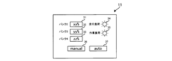
- FIG. 2 is a schematic view showing a specific display example on the display device 11.
- the screen of the display device 11 is formed as a touch panel, and is configured to also function as the input device 9.
- indicators 34 for displaying the driving states of the traveling load 6a and the work load 6b of the load device 6 by lighting are displayed.
- touch panel icons 36 and 37 for selecting whether to manually or automatically control the battery system 100 are displayed.
- the automatic control referred to here is control for automatically performing charge / discharge control of the bank based on operation information described below.
- the charge amount display unit 31, 32 the battery system is manually operated so that the input charge amount is discharged by directly inputting the charge amount of the banks 2, 3 and 4 intended by the user via the input device 9 such as a keyboard or the like.
- Charge and discharge control As a specific example of the situation where manual control is required, when the waste collection vehicle 1 needs to consume power deviating from the operation information, for example, the case where the collected amount of waste is temporarily increased rapidly may be considered.
- the BMUs 12, 13, and 14 are units having a function of acquiring and storing charge / discharge information of the banks 2, 3, and 4.
- the charge / discharge information includes, for example, information specific to the battery such as the rated capacity, temperature characteristics, storage characteristic, etc. of the banks 2, 3 and 4, and information on the charge / discharge status of the battery such as charge amount, discharge amount, charge count.
- the charge / discharge information acquired and stored by the BMUs 12, 13, 14 is appropriately read by the controller 15 and used for various calculations.
- the acquisition and storage of the charge / discharge information from the banks 2, 3, 4 by the BMUs 12, 13, 14 may be performed at a fixed or indeterminate timing.
- BMU12, 13, 14 is an example of the "charge amount acquisition means" which concerns on this invention.
- the controller 15 transmits and receives control signals to and from the charging device 5 and the power control circuit 7 based on the operation information read from the storage device 10 and the charge / discharge information read from the BMUs 12, 13 and 14,
- the control circuit 7 is controlled to perform charge / discharge control of the banks 2, 3, 4.
- the specific control contents of the controller 15 will be described later.
- FIG. 3 is a circuit block diagram showing a circuit configuration of power control circuit 7.
- the same parts as those in the configuration shown in FIG. 1 will be denoted by the same reference numerals, and the description will be omitted as appropriate.
- the power control circuit 7 has a configuration in which switches of switches SW1 to SW6 are electrically connected to each other by wires.
- One end of the switches SW1, SW2 and SW3 is electrically connected to the positive electrode side of the banks 2, 3 and 4, and the other end is electrically connected to the switches SW4, SW5 and SW6.
- One end of the switch SW4 is electrically connected to the positive electrode side of the charging device 5, and one end of the switch SW6 is electrically connected to the positive electrode side of the load device 6.
- the switches SW7, SW8 and SW9 are electrically connected to the negative sides of the banks 2, 3 and 4, and particularly one end of the switches SW7 and SW9 is connected to the negative sides of the charging device 5 and the load device 6, respectively. Then, by operating SW4 and SW7, SW5 and SW8, and SW6 and SW9 as a pair, it is possible to switch the connection state between each of the banks 2, 3 and 4 and the charging device 5 and the load device 6. Is configured.
- the positive terminals of the banks 2, 3 and 4 are connected to the switches SW1, SW2 and SW3, while the negative terminals of the banks 2, 3 and 4 are shorted together with the charging device 5 and the load device 6.
- the switches SW1 to SW6 constituting the power control circuit 7 are switched on / off by a control signal from the controller 15. As described above, by switching and controlling the switches SW1 to SW6 according to the control signal from the controller 15, charging from the charging device 5 or discharging to the load device 6 is individually performed for each of the banks 2, 3 and 4. It is configured to be able to control.
- a configuration of the power control circuit 7, a circuit shown in FIG. 3 (b) may be adopted. In the example shown in FIG.
- FIG. 3B the connection destinations of banks 2, 3 and 4 are switched to either charging device 5 or load device 6 by switching on / off switches SW11 to SW25 according to a control signal from controller 15. It is possible to switch more flexibly than in the case of FIG. 3 (a).
- FIG. 3B does not show the supply route of the control signal from the controller 15 to the switch SW11 to the switch 25 in order to show the configuration of the power control circuit 7 in an easily understandable manner, FIG. Similarly, by supplying a control signal from the controller 15 to each of the switches SW11 to SW25, the on / off of each switch can be switched.
- the BMUs 12, 13 and 14 acquire and store charge / discharge information of the banks 2, 3 and 4 respectively, and the controller 15 accesses the BMUs 12, 13 and 14 to obtain the BMUs 12, 13 and 13. It is comprised so that the charge / discharge information memorize
- FIG. 4 is a diagram showing an operation pattern of the load device 6 defined by the operation information stored in the storage device 10.
- “one day” is assumed as the operation cycle of the refuse collection vehicle 1.
- the operation cycle is divided into periods (periods T1 to T5) in which the driving states of the traveling load 6a and the work load 6b change, and the driving states of the traveling load 6a and the work load 6b in each period and the external commercial power supply It defines the availability of charging.
- the period T1 is defined as a period in which only the traveling load 6a of the load device 6 is driven (in short, the work load 6b is not driven) and charging can not be performed from the external commercial power supply. Specifically, the period T1 corresponds to a moving period in which the garbage collection vehicle 1 travels from the storage base to the site where the garbage collection work is performed. In the period T1, since the garbage collection vehicle 1 is in the traveling state, the charging device 5 can not be connected to the stationary commercial power source for charging, and the bank can not be charged.
- the period T2 is defined as a period in which the traveling load 6a and the work load 6b are both driven and charging from an external commercial power source can not be performed. Specifically, the period T2 corresponds to a period in which the garbage collection vehicle 1 arrives at the site where the garbage collection work is performed, and the garbage collection work is repeatedly performed while traveling around the garbage collection places. In the period T2, since the garbage collection vehicle 1 is in a traveling state, the charging device 5 can not be connected to the stationary commercial power source for charging, and the bank can not be charged.
- the period T3 is defined as a period in which only the work load 6b of the load device 6 is driven (in short, the traveling load 6a is not driven), and charging from an external commercial power source is possible. Specifically, after the waste collection work is completed in period T2, period T3 stops the waste collection vehicle 1 at the waste treatment facility, and the collected waste compressed and stored in the box-shaped container in the waste collection vehicle 1 is Corresponds to a period of time when the work load 6b is driven to discharge the dust collection car 1 out. In period T3, a commercial power source for charging is fixedly provided in the refuse disposal facility where the refuse collection vehicle 1 is stopped, and charging of the bank is possible by connecting the charging device 5 to the commercial power source. It is.
- period T4 is defined as a period in which only the traveling load 6a of the load device 6 is driven (in short, the work load 6b is not driven), and charging from an external commercial power source can not be performed.
- period T4 corresponds to a return period in which the waste collection vehicle 1 whose discharge operation of collected waste is completed in the waste treatment facility travels toward the storage base of the waste collection vehicle 1.
- the period T5 is defined as a period in which the traveling load 6a and the work load 6b are not driven together and charging from an external commercial power source can not be performed. Specifically, the period T5 corresponds to a period (for example, nighttime) in which the refuse collection vehicle 1 returned to the storage base is stored in the storage base.
- a commercial power source for charging is fixedly provided at the storage base where the refuse collection vehicle 1 is stopped, and charging the bank is possible by connecting the charging device 5 to the commercial power source. is there.
- the controller 15 estimates the power consumption pattern in the operation cycle based on the operation pattern of the load device 6 defined by the operation information as described above.
- the amount of power consumed when the traveling load 6 a and the work load 6 b are driven for a predetermined period is stored in the storage device 10 as data in advance, and the controller 15 accesses the storage device 10 to access the data To estimate the power consumption of each period.
- the amount of power consumed when the traveling load 6a and the work load 6b stored in the storage device 10 are driven for a predetermined period is the operation result of the waste collection vehicle 1 in the past (for example, the traveling load 6a and the work load 6b) May be calculated on the basis of an actual measurement value of the power consumption amount generated in the case of driving in the past.
- FIG. 5 is a graph showing the power consumption pattern estimated by the controller 15 based on the operation information shown in FIG.
- the horizontal axis represents time
- the vertical axis represents estimated power consumption (hereinafter referred to as “estimated power consumption” as appropriate).
- the estimated power consumption P1 of the period T1 is the power consumption estimated as the power consumption by the traveling load 6a driven in the period T1.
- the estimated power consumption P2 of the period T2 is the power consumption estimated as the power consumption by the traveling load 6a and the work load 6b driven in the period T2, and the amount of driving by the work load 6b is added compared to the period T1, It is larger than P1.
- estimated power consumption P2 is also fluctuate
- the estimated power consumption P3 in the period T3 is the power consumption estimated as the power consumption by the work load 6b driven in the period T3, and is smaller than P2 because the driving load 6a is not driven compared to the period T2 It has become. Since the work load 6b driven in the period T3 is alternately switched between the drive and the stop depending on the dust discharge state, the estimated power consumption P3 also fluctuates according to the switching timing.
- the estimated power consumption P4 of the period T4 is the power consumption estimated as the power consumption by the traveling load 6a driven in the period T4.
- the estimated power consumption P5 in the period T5 is zero because the load device 5 is not driven at all in the period T5.
- the controller 15 “charges”, “discharges”, “charges” the state of the banks 2, 3 and 4 for each period so that the estimated power consumption shown in FIG. 5 can be covered by the power discharged from the banks 2, 3 and 4. Set to one of "wait”.
- An example of such state setting control for each period of each bank is shown in FIG. 6 and FIG.
- FIG. 6 is a table showing the state of each bank for each period
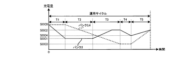
- FIG. 7 is a graph showing the transition of the charge amount of each bank when the state setting control is performed as shown in FIG.
- the state of the bank 2 is set to "discharge", and the states of the banks 3 and 4 are set to "standby". This is because the estimated power consumption P1 in the period T1 is relatively small, and the discharge from only the bank 2 covers the estimated power consumption P1. In other words, the total capacity of the banks contributing to the discharge is the largest estimated required power P1 without performing inefficient charge / discharge control to discharge all banks 2, 3 and 4 in order to cover small estimated power consumption P1.
- the state of each bank is set to discharge only from the bank 2 so as to be close.
- the states of the banks 3 and 4 not contributing to the discharge are set to "standby" instead of "charging".
- bank 2 is selected from banks 2, 3 and 4 as a bank for covering estimated power consumption P1 in period T1
- bank 3 or bank 4 may be selected instead of bank 2.
- the discharge frequency of only a specific bank becomes high when repeating the operation cycle, the battery life of each bank varies. In order to prevent such variations in battery life, it is preferable to perform control such that the selected bank is randomly changed.
- the state of the bank 2 is set to "standby", and the states of the banks 3 and 4 are set to "discharge”. This is because, during the period T2, the estimated power consumption P2 can be covered by discharging from the banks 3 and 4 in which the charge amount remains rich compared to the bank 2.
- the estimated power consumption P2 is larger than the estimated power consumption P1, even if the estimated power consumption P2 is too large to be available in a single bank, discharge from the two banks in this way It can respond by doing.
- the state of the bank 2 not contributing to the discharge is set to "standby" instead of "charging".
- the state of the bank 2 is set to "charge”, and the states of the banks 3 and 4 are set to "discharge".
- the amount of charge of bank 2 is smaller than that of banks 3 and 4. Therefore, the amount of charge is restored by preferentially charging bank 2 with a small amount of charge, and This is because it is desirable to perform discharge using banks 3 and 4 which have a relatively large margin.
- the discharge from the banks 3 and 4 is simultaneously performed, and at the same time, the charge and discharge control is made more efficient by charging the bank 2.
- the power consumption is calculated using the bank 2 whose charge amount is recovered in the period T3. It will be possible to crawl.
- the charging device 5 stops the charging to prevent the overcharging to the bank 2, and thereafter, the state of the bank 2 is automatically "standby" Transition to Thus, overcharging of the bank 2 can be prevented, and the life of the bank 2 can be increased.
- the state of the bank 2 is set to "discharge", and the states of the banks 3 and 4 are set to "standby".
- the state of each bank in the period T4 in this manner, the charge amount of the bank 2 is reduced while the charge amounts of the banks 3 and 4 are maintained constant.
- period T5 the states of banks 2, 3 and 4 are all set to "charge". Since the estimated power consumption P5 of the period T5 is zero, it is not necessary to perform discharge. Moreover, in period T5, it is possible to charge by connecting the charging device 5 to the commercial power supply installed in the storage base. Therefore, in period T5 which is the final period of the operation cycle, banks 2, 3 and 4 are sufficiently charged in a range not to be overcharged in preparation for the next operation cycle (that is, operation on the next day). By setting the state of each bank in period T5 in this manner, the charge amount of banks 2, 3 and 4 both increase.
- FIG. 8 is a flowchart showing processing executed by the controller 15 to perform state setting control in each of the banks 2, 3 and 4.
- FIG. 8 is a flowchart showing processing executed by the controller 15 to perform state setting control in each of the banks 2, 3 and 4.
- the controller 15 acquires operation information input by the user via the input device 9 (step S101), and stores the operation information in the storage device 10 (step S102).
- the input operation of the operation information by the user be performed periodically, for example, in accordance with the operation cycle.
- the operation cycle of the waste collection vehicle 1 since “one day” is adopted as the operation cycle of the waste collection vehicle 1, when the operation time of that day is over (for example, after the waste collection vehicle 1 finished the work on the day returns to the storage base It is good to do the input work of the operation information corresponding to the next operation day to).
- the length of the operation cycle of the refuse collection vehicle 1 another one day, one week, one month, etc. may be set.
- the controller 15 accesses the storage device 10 to read out the operation information stored in the storage device 10 (step S103), and estimates the estimated power consumption in each period of the operation cycle based on the operation information (step S103) S104).
- the controller 15 functions as the "estimation means" according to the present invention.
- the specified power consumption may be used as the estimated power consumption as it is. In this case, step S104 may be omitted.
- the controller 15 sets the state of the banks 2, 3 and 4 to any one of “charge”, “discharge” and “standby” for each period so as to cover the estimated power consumption estimated in step S104 Step S105). Then, the power control circuit 7 is switched to control the charge / discharge state of the banks 2, 3 and 4 so that the state of the banks 2, 3 and 4 becomes the state set in step S105 (step S106).
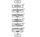
- FIG. 9 is a flow chart showing processing of state setting control of each bank performed in step S105 of FIG. In this process, an increment variable n corresponding to each period T1 to T5 of the operation cycle is introduced, and the state of banks 2, 3 and 4 in each period is sequentially set by counting the increment variable n. Control is performed.
- step S201 the controller 15 reads the estimated power consumption P1 in the period T1 estimated in step S104 (step S202).
- the controller 15 accesses the BMUs 12, 13 and 14 to acquire the charge amounts of the banks 2, 3 and 4 (step S203). Then, based on the charge amount of the banks 2, 3 and 4, in order to cover the estimated power consumption P1 read in step S202, a bank whose state is set to "discharge" is selected (step S204).
- the bank 2 is selected as the bank whose state is set to "discharge". That is, the bank is selected such that discharge is performed only from the bank 2 without performing inefficient control to discharge all the banks 2, 3 and 4 in order to cover small estimated power consumption P1.
- the controller 15 determines whether charging is possible by connecting the charging device 5 to the commercial power supply in the period T1 (step S205). Specifically, as shown in FIG. 4, the determination is made by referring to the availability of the charge defined in the operation information. Incidentally, in the period T1, as shown in FIG. 4, it is determined that charging is not possible.
- step S206 determines whether or not there is.
- a predetermined threshold for example, a threshold corresponding to the charge amount to be overdischarged
- step S207 the state of the bank during the period T1 is set to "charging"
- step S208 when charging is not possible (step S205: NO) or when it is determined that charging is not required (step S206: NO), the states of banks 3 and 4 in period T1 are set to "standby". (Step S208).
- step S209 increment variable n is incremented by one (step S209), and state setting control of banks 2, 3 and 4 in period T2 is performed (step S210: NO). Thereafter, the states of banks 2, 3 and 4 in periods T2 to T5 are set by repeatedly executing steps S202 to S207 described above.
- step S204 the bank The states of 3 and 4 are set to "discharge” (step S204).
- step S208 the state of the bank 2 is set to "standby" (step S208) because charging is not possible in the period T2 (step S205: NO).
- step S204 the states of the banks 3 and 4 are set to "discharge” (step S204).
- step S205: YES the state of bank 2 is set to "charging” because charging is possible in period T3
- step S206 YES
- step S207 the amount of charge of bank 2 is small
- the estimated power consumption P4 is the same as the estimated power consumption P1 in period T1, so the state of bank 2 is set to "discharge” and the states of banks 3 and 4 are set to "standby". Be done.
- step S205 since the estimated power consumption P5 is zero, the state of the bank is not set to "discharge". On the other hand, in the period T5, charging is possible (step S205: YES), and the charge amount of the banks 2, 3 and 4 is small (step S206: YES). Is set (step S207).
- step S210 when the state setting of the banks 2, 3 and 4 in each period is completed (step S210: YES), the controller 15 ends the series of processing (END).
- the past operation results are, for example, the operating states of the traveling load 6a and the work load 6b in each period (T1 to T5) when the garbage collection vehicle 1 is operated (specifically refer to FIG. 4), and It is stored in the storage device 10 in association with the transition of the power consumption (specifically, refer to FIG. 7).
- the power consumption pattern is statistically estimated.
- the controller 15 acquires an increment variable k from the storage device 10 (step S301), and determines whether the acquired increment variable k is "1" (step S302). That is, in this step, it is determined whether or not the past operation results exist in the storage unit 10.
- the controller 15 sets the manufacturer recommended value of the banks 2, 3 and 4 (for example, voltage range, maximum discharge current value, maximum charge current value, operating temperature range Etc.) (step S303).
- the manufacturer recommended value is stored in advance in the storage device 10, and can be acquired by the controller 15 accessing it.
- the user uses the touch panel displayed on the display device 11 to determine which bank out of the banks 2, 3 and 4 is to be used for discharging or charging in each period (that is, periods T1 to T5) of the operation cycle.
- the setting is input (step S304).
- An example of the touch panel displayed on the display device 11 when performing the input operation is shown in FIG. As shown in FIG. 11, the touch panel is provided with an icon which can select whether the bank 2, 3 or 4 is in the state of "discharge”, “charge” or “standby” in each period. It is configured that the user can input the state of the banks 2, 3 and 4 in each period by touching.
- step S305 the operation of the garbage collection vehicle 1 is started according to the contents input through the touch panel in this manner (step S305).
- the power consumption patterns of banks 2, 3 and 4 in each period that is, periods T1 to T5 are acquired, and the acquired power consumption patterns are correlated with the input contents from the touch panel to obtain past operation results. It is stored in the storage device 10 (step S306).
- the controller 15 adds “1” to the increment variable k and stores the same in the storage device 10 to update the increment variable k (steps S307 & S308).
- step S301 If the increment variable k acquired in step S301 is not "1" (step S302: NO), the controller 15 further determines whether the increment variable k is "2" (step S309). That is, in this step, it is determined whether or not there are a plurality of past operation results in the storage unit 10.
- step S304 the user uses the touch panel displayed on the display device 11 to select which bank out of banks 2, 3 and 4 in each period.
- setting or inputting whether discharging or charging is to be performed is performed (step S310).
- step S311 it is determined whether the content input in step S310 is the same as the past operation record stored in step S306 (step S311). If it is the same as the past operation results stored in step S306 (step S311: YES), banks 2, 3 and 4 are charged according to the same charge / discharge pattern as the past operation results plus the safety factor. Operation is started to perform discharge control (step S312).
- the safety factor refers to the charging of each bank 2, 3, 4 in the charge / discharge pattern so that the charge amount (ie, SOC) of each bank 2, 3, 4 in the charge / discharge pattern does not become overdischarged or overcharged. It is a so-called margin added to the rate.
- step S312 As a result of the operation of the garbage collection vehicle 1 in step S312, it is correlated with the input content in step S310 which one of the banks 2, 3 and 4 is used for charging or discharging in each period, The past operation results are stored in the storage device 10 (step S313). Thereafter, the controller 15 adds “1” to the increment variable k and updates the increment variable k by storing the same in the storage device 10 (steps S314 & S315), and returns the process to step S301 to further explain the process described below. Migrate to
- step S311 NO
- the operation result is accumulated by repeatedly executing the above-described steps S303 to S308.
- step S306 since there is not a plurality of past operation records, statistical estimation processing as in step S316 and subsequent steps can not be performed. Therefore, in the next processing turn, accumulation of past operation results is achieved by repeatedly executing the processing from step S303 to step S308 so that statistical estimation processing can be performed using a plurality of past operation results. .
- step S309 NO
- the controller 15 acquires a plurality of past operation results from the storage device 10 (step S316).
- the controller 15 acquires an external factor which is a factor of the variation of the plurality of past operation results (step S317).
- the external factor is, for example, the predicted value of the amount of collected dust on the day of operation, and the fluctuation of weather (such as the temperature and humidity of the outside air).
- Such external factors may be acquired by the user using the input device 9 in the former case, or an external air temperature sensor or vehicle speed sensor (provided in the dust collection vehicle 1) in the latter case. Detection values from various sensors such as not shown in FIG. 1 may be acquired.
- Step S3128 the charge / discharge patterns of banks 2, 3 and 4 in each period of the operation cycle are statistically estimated.
- the amount of change with time in SOC of each bank 2, 3 and 4 is statistically determined.
- the mean value ⁇ and the standard deviation ⁇ is calculated.
- bank 2 in each period of the operation cycle is included so that the charge / discharge pattern estimated is included in the range of ⁇ ⁇ n ⁇ (n is an integer set according to the magnitude of the external factor acquired in step S317).
- 3 and 4 are statistically estimated.
- the estimation process is statistically performed after each period in the operation cycle is defined in advance, but the estimation process may be performed in time units in addition to such period units. . Further, the estimation process may be performed with the earliest start time, the latest finish time, or the intermediate time between the earliest start time and the latest finish time of each period as a unit.
- the garbage collection vehicle 1 When the garbage collection vehicle 1 is operated according to the charge / discharge patterns of the banks 2, 3 and 4 estimated in this manner, the banks 2, 3 and 4 are overcharged or added by adding a predetermined safety factor. It is better to reduce the risk of overdischarge. In this case, it is preferable that the predetermined safety factor is also determined by statistical processing based on past operation results.
- the connection state between the banks 2, 3 and 4 and the charging device 5 is controlled by controlling the power control circuit 7 based on the operation information, and Since it is possible to switch the connection state between 2, 3, and 4 and the load device 6, according to the operation pattern of the dust collection vehicle 1 in the operation cycle, to some assembled batteries selected from the banks 2, 3 and 4.
- flexible charging and discharging control can be realized by performing charging by the charging device 5 and discharging the load device 6 from other assembled batteries.
- the present invention comprises, for example, a plurality of assembled batteries comprising a plurality of secondary battery cells mounted on a mobile unit having a load device including a plurality of target loads powered by different powers for different purposes.
- the present invention can be used in a mobile battery system and a charge control method of the battery system.
Landscapes
- Engineering & Computer Science (AREA)
- Power Engineering (AREA)
- Manufacturing & Machinery (AREA)
- General Chemical & Material Sciences (AREA)
- Electrochemistry (AREA)
- Chemical Kinetics & Catalysis (AREA)
- Chemical & Material Sciences (AREA)
- Sustainable Development (AREA)
- Mechanical Engineering (AREA)
- Transportation (AREA)
- Sustainable Energy (AREA)
- Life Sciences & Earth Sciences (AREA)
- Charge And Discharge Circuits For Batteries Or The Like (AREA)
- Secondary Cells (AREA)
- Electric Propulsion And Braking For Vehicles (AREA)
Abstract
Description
本発明の移動体用電池システムの制御方法によれば、上述の移動体用電池システム(各態様を含む)を実現することが可能である。
尚、電力制御回路7の構成として、図3(b)に示す回路を採用してもよい。図3(b)に示す例では、スイッチSW11からSW25をコントローラ15からの制御信号に従ってオン/オフ切り替えすることによって、バンク2,3,4の接続先を充電装置5又は負荷装置6のいずれにするかを、図3(a)の場合に比べて、より柔軟に切り替えることができる。尚、図3(b)では電力制御回路7の構成をわかりやすく示すために、コントローラ15からスイッチSW11からSW25への制御信号の供給ルートの図示を省略しているが、図3(a)と同様に、コントローラ15からスイッチSW11からSW25の各々に対して制御信号を供給することによって、各スイッチのオン/オフを切り替えすることができるように構成されている。
Claims (10)
- 充電装置と、互いに異なる目的のために電力駆動される複数の目的負荷を含んでなる負荷装置とを有する移動体に搭載され、
複数の二次電池セルを直列又は並列に接続してなる複数の組電池と、
前記複数の組電池と前記充電装置との接続状態、及び、前記複数の組電池と前記負荷装置との接続状態を切り替えるための電力制御回路と
を備える移動体用電池システムにおいて、
前記移動体の運用サイクルにおける前記複数の目的負荷の各々の運用パターンに関する運用情報を記憶する記憶手段と、
前記記憶された運用情報に基づいて前記運用サイクルにおける電力消費パターンを推定する推定手段と、
前記推定手段によって推定された電力消費パターンに従って前記負荷装置による消費電力を賄うように前記電力制御回路を切り替え制御する制御手段と
を備えることを特徴とする移動体用電池システム。 - 前記制御手段は、
前記推定手段によって推定された電力消費パターンから前記運用サイクル内の所定期間における消費電力量を算出し、
前記複数の組電池のうち前記消費電力を賄うために電力を放電する組電池の前記所定期間における放電量の合計が、前記算出された消費電力量より大きくなるように前記電力制御回路を切り替え制御することを特徴とする請求項1に記載の移動体用電池システム。 - 前記制御手段は、
前記推定手段によって推定された電力消費パターンから前記運用サイクル内の所定期間における消費電力量を算出し、
前記複数の組電池のうち前記消費電力を賄うために電力を放電する組電池の前記所定期間における放電量の合計が、前記算出された消費電力量に最も近くなるように前記電力制御回路を切り替え制御することを特徴とする請求項1に記載の移動体用電池システム。 - 前記複数の組電池の現在の充電量を取得する充電量取得手段を更に備え、
前記制御手段は、前記取得した充電量が所定の範囲内に収まるように前記電力制御回路を制御することを特徴とする請求項1から3のいずれか一項に記載の移動体用電池システム。 - 前記運用情報を入力するための入力手段を更に備えることを特徴とする請求項1から4のいずれか一項に記載の移動体用電池システム。
- 前記複数の目的負荷は、前記移動体を走行させるための走行負荷と、前記移動体に走行以外の作業を行わせる作業負荷とを含むことを特徴とする請求項1から5のいずれか一項に記載の移動体用電池システム。
- 前記走行負荷及び前記作業負荷は、独立して駆動可能であることを特徴とする請求項6に記載の移動体用電池システム。
- 前記複数の二次電池セルはリチウムイオン電池セルであることを特徴とする請求項1から7のいずれか一項に記載の移動体用電池システム。
- 充電装置と、互いに異なる目的のために電力駆動される複数の目的負荷を含んでなる負荷装置とを有する移動体に搭載され、
複数の二次電池セルを直列又は並列に接続してなる複数の組電池と、
前記複数の組電池の各々と前記充電装置との接続状態、及び、前記複数の組電池の各々と前記負荷装置との接続状態を切り替えるための電力制御回路と
を備える移動体用電池システムの制御方法において、
前記移動体の運用サイクルにおける前記複数の目的負荷の各々の運用パターンに関する運用情報に基づいて前記運用サイクルにおける電力消費パターンを推定する推定工程と、
当該推定された電力消費パターンに従って前記負荷装置による消費電力を賄うように前記電力制御回路を切り替え制御する制御工程と
を備えることを特徴とする移動体用電池システムの制御方法。 - 請求項1から8のいずれか一項に記載の移動体用電池システムを備えた産業用車両。
Priority Applications (2)
| Application Number | Priority Date | Filing Date | Title |
|---|---|---|---|
| CN2011800358463A CN103026581A (zh) | 2010-07-29 | 2011-07-27 | 移动体用电池系统以及移动体用电池系统的控制方法 |
| US13/811,191 US9136726B2 (en) | 2010-07-29 | 2011-07-27 | Battery system for movable object and controlling method for the same |
Applications Claiming Priority (2)
| Application Number | Priority Date | Filing Date | Title |
|---|---|---|---|
| JP2010171069A JP4691198B1 (ja) | 2010-07-29 | 2010-07-29 | 移動体用電池システム及び移動体用電池システムの制御方法 |
| JP2010-171069 | 2010-07-29 |
Publications (1)
| Publication Number | Publication Date |
|---|---|
| WO2012014941A1 true WO2012014941A1 (ja) | 2012-02-02 |
Family
ID=44236976
Family Applications (1)
| Application Number | Title | Priority Date | Filing Date |
|---|---|---|---|
| PCT/JP2011/067129 Ceased WO2012014941A1 (ja) | 2010-07-29 | 2011-07-27 | 移動体用電池システム及び移動体用電池システムの制御方法 |
Country Status (4)
| Country | Link |
|---|---|
| US (1) | US9136726B2 (ja) |
| JP (1) | JP4691198B1 (ja) |
| CN (1) | CN103026581A (ja) |
| WO (1) | WO2012014941A1 (ja) |
Cited By (3)
| Publication number | Priority date | Publication date | Assignee | Title |
|---|---|---|---|---|
| JP2016086514A (ja) * | 2014-10-24 | 2016-05-19 | Jfeエンジニアリング株式会社 | 電力供給システムおよびごみ処理システム |
| US20160193935A1 (en) * | 2012-12-24 | 2016-07-07 | H&D Electric, LLC | Advances in Electric Car Technology |
| US9927507B2 (en) | 2012-06-27 | 2018-03-27 | Hitachi, Ltd. | Gradient magnetic field coil device and magnetic resonance imaging device |
Families Citing this family (34)
| Publication number | Priority date | Publication date | Assignee | Title |
|---|---|---|---|---|
| JP6025197B2 (ja) * | 2010-04-26 | 2016-11-16 | 日本電気株式会社 | 電力制御システム及び方法 |
| JP5156112B2 (ja) * | 2011-07-28 | 2013-03-06 | 三菱重工業株式会社 | 電池システム |
| JP6157880B2 (ja) * | 2013-03-04 | 2017-07-05 | 株式会社東芝 | 複数電池を有する二次電池システム及び充放電電力等の配分方法 |
| US20140274219A1 (en) * | 2013-03-14 | 2014-09-18 | Telect Inc. | Telecommunication Power System |
| CA2900352C (en) * | 2013-03-15 | 2023-02-14 | Crown Equipment Corporation | Normalizing performance data across industrial vehicles |
| JP6371845B2 (ja) * | 2013-07-23 | 2018-08-08 | コーニンクレッカ フィリップス エヌ ヴェKoninklijke Philips N.V. | 太陽光発電及びバッテリ動作システム並びにそれを制御するための方法 |
| DE102014210187B4 (de) * | 2014-05-28 | 2026-03-19 | Robert Bosch Gmbh | Verfahren zum Betreiben einer Sekundärbatterie |
| CN107078360A (zh) * | 2014-08-22 | 2017-08-18 | 佩颂股份有限公司 | 在能量系统中进行串级动态重新配置的方法和装置 |
| JP6332066B2 (ja) * | 2015-02-06 | 2018-05-30 | Jfeエンジニアリング株式会社 | 可搬式バッテリ管理システム及びごみ処理システム |
| US10594150B2 (en) * | 2015-04-24 | 2020-03-17 | Manodya Limited | Pulse discharge system |
| US10110023B2 (en) * | 2015-04-24 | 2018-10-23 | Manodya Limited | Power supply system |
| US9692244B2 (en) * | 2015-09-08 | 2017-06-27 | Yung Ju Lee | Charging means and apparatus for secondary battery |
| US20170229880A1 (en) * | 2016-02-05 | 2017-08-10 | Indian Institute Of Technology Madras (Iitm) | Complementary engagement of battery banks to augment life, performance and capacity of energy storage system |
| US10361567B2 (en) * | 2016-02-05 | 2019-07-23 | Indian Institute Of Technology Madras (Iitm) | Complementary engagement of battery banks to augment life, performance and capacity of energy storage system |
| JP6883396B2 (ja) * | 2016-08-25 | 2021-06-09 | 矢崎総業株式会社 | 急速充電装置 |
| US10732226B2 (en) | 2017-05-26 | 2020-08-04 | Hand Held Products, Inc. | Methods for estimating a number of workflow cycles able to be completed from a remaining battery capacity |
| DE102017210618A1 (de) | 2017-06-23 | 2018-12-27 | Audi Ag | Elektrische Energieliefervorrichtung mit einer Vielzahl von Nutzeinheiten, die zu Strängen verschaltet sind, sowie Verfahren zum Betreiben der Energieliefervorrichtung |
| TWI689152B (zh) * | 2018-03-09 | 2020-03-21 | 華碩電腦股份有限公司 | 電池管理裝置 |
| GB2570356B (en) * | 2018-05-29 | 2020-01-15 | Manodya Ltd | A pulse discharge system |
| DE102018213180A1 (de) * | 2018-08-07 | 2020-02-13 | Thyssenkrupp Ag | Verfahren zur Regelung des Netzes eines Unterwasserfahrzeugs und Unterwasserfahrzeug, welches zu einer derartigen Regelung ausgestaltet ist |
| US10326305B1 (en) | 2018-08-27 | 2019-06-18 | Ekergy Llc | Personal power plant system and methods of inverse energy generation |
| EP3626489A1 (en) | 2018-09-19 | 2020-03-25 | Thermo King Corporation | Methods and systems for energy management of a transport climate control system |
| EP3626490A1 (en) | 2018-09-19 | 2020-03-25 | Thermo King Corporation | Methods and systems for power and load management of a transport climate control system |
| ES2982673T3 (es) | 2018-12-31 | 2024-10-17 | Thermo King Llc | Métodos y sistemas para notificar y mitigar un evento subóptimo que se produce en un sistema de control de climatización de transporte |
| EP3906175A1 (en) | 2018-12-31 | 2021-11-10 | Thermo King Corporation | Methods and systems for providing predictive energy consumption feedback for powering a transport climate control system using external data |
| EP3906174B1 (en) | 2018-12-31 | 2024-05-29 | Thermo King LLC | Methods and systems for providing feedback for a transport climate control system |
| EP3906173B1 (en) | 2018-12-31 | 2024-05-22 | Thermo King LLC | Methods and systems for providing predictive energy consumption feedback for powering a transport climate control system |
| US11597297B2 (en) | 2019-05-03 | 2023-03-07 | Oshkosh Corporation | Electronic control system for electric refuse vehicle |
| US10615610B1 (en) | 2019-05-28 | 2020-04-07 | Ekergy Llc | System and method for efficient charging of multiple battery cassettes |
| KR102679823B1 (ko) * | 2019-09-06 | 2024-07-03 | 주식회사 엘지에너지솔루션 | 배터리 시스템 및 배터리 시스템의 제어방법 |
| US11135894B2 (en) * | 2019-09-09 | 2021-10-05 | Thermo King Corporation | System and method for managing power and efficiently sourcing a variable voltage for a transport climate control system |
| CN114084043B (zh) * | 2020-10-16 | 2024-03-08 | 格力博(江苏)股份有限公司 | 电池管理系统、电池管理方法以及电动车辆 |
| JP7499802B2 (ja) * | 2022-03-30 | 2024-06-14 | 本田技研工業株式会社 | 制御装置、移動体、方法及びプログラム |
| CN115208022A (zh) * | 2022-07-29 | 2022-10-18 | 三一汽车制造有限公司 | 供电系统及作业机械 |
Citations (4)
| Publication number | Priority date | Publication date | Assignee | Title |
|---|---|---|---|---|
| JPH09298806A (ja) * | 1996-05-01 | 1997-11-18 | Yamaha Motor Co Ltd | 電動車両用電力供給方法及びその装置 |
| JP2001045673A (ja) * | 1999-08-03 | 2001-02-16 | Tokyo R & D Co Ltd | 電動装置及びその電池ユニットの充放電方法 |
| JP2004147477A (ja) * | 2002-10-28 | 2004-05-20 | Komatsu Ltd | 電動機の電源装置 |
| JP2006296109A (ja) * | 2005-04-12 | 2006-10-26 | Toyotomi Co Ltd | 家庭用小型電源装置 |
Family Cites Families (9)
| Publication number | Priority date | Publication date | Assignee | Title |
|---|---|---|---|---|
| JP3171079B2 (ja) * | 1995-07-24 | 2001-05-28 | トヨタ自動車株式会社 | 車両用駆動制御装置 |
| US5841201A (en) * | 1996-02-29 | 1998-11-24 | Toyota Jidosha Kabushiki Kaisha | Hybrid vehicle drive system having a drive mode using both engine and electric motor |
| US6621250B1 (en) * | 1999-09-09 | 2003-09-16 | Toyota Jidosha Kabushiki Kaisha | Battery capacity measuring and remaining capacity calculating system |
| JP3932098B2 (ja) * | 2002-01-31 | 2007-06-20 | 株式会社デンソー | 車両用配電装置およびユーザー後付け負荷接続用の補助端子 |
| US6988024B2 (en) * | 2003-08-29 | 2006-01-17 | Matsushita Electric Industrial Co., Ltd. | Cogeneration system, operation controller for cogeneration facility, and operation program for cogeneration facility |
| US7355292B2 (en) * | 2005-06-02 | 2008-04-08 | Denso Corporation | Power generation control apparatus for internal combustion engine |
| JP5104077B2 (ja) * | 2007-07-04 | 2012-12-19 | トヨタ自動車株式会社 | 電動車両 |
| JP5368038B2 (ja) * | 2008-09-11 | 2013-12-18 | ミツミ電機株式会社 | 電池状態検知装置及びそれを内蔵する電池パック |
| CN101508381B (zh) * | 2009-03-23 | 2011-04-27 | 北京理工大学 | 一种压缩式垃圾车 |
-
2010
- 2010-07-29 JP JP2010171069A patent/JP4691198B1/ja active Active
-
2011
- 2011-07-27 CN CN2011800358463A patent/CN103026581A/zh active Pending
- 2011-07-27 US US13/811,191 patent/US9136726B2/en active Active
- 2011-07-27 WO PCT/JP2011/067129 patent/WO2012014941A1/ja not_active Ceased
Patent Citations (4)
| Publication number | Priority date | Publication date | Assignee | Title |
|---|---|---|---|---|
| JPH09298806A (ja) * | 1996-05-01 | 1997-11-18 | Yamaha Motor Co Ltd | 電動車両用電力供給方法及びその装置 |
| JP2001045673A (ja) * | 1999-08-03 | 2001-02-16 | Tokyo R & D Co Ltd | 電動装置及びその電池ユニットの充放電方法 |
| JP2004147477A (ja) * | 2002-10-28 | 2004-05-20 | Komatsu Ltd | 電動機の電源装置 |
| JP2006296109A (ja) * | 2005-04-12 | 2006-10-26 | Toyotomi Co Ltd | 家庭用小型電源装置 |
Cited By (3)
| Publication number | Priority date | Publication date | Assignee | Title |
|---|---|---|---|---|
| US9927507B2 (en) | 2012-06-27 | 2018-03-27 | Hitachi, Ltd. | Gradient magnetic field coil device and magnetic resonance imaging device |
| US20160193935A1 (en) * | 2012-12-24 | 2016-07-07 | H&D Electric, LLC | Advances in Electric Car Technology |
| JP2016086514A (ja) * | 2014-10-24 | 2016-05-19 | Jfeエンジニアリング株式会社 | 電力供給システムおよびごみ処理システム |
Also Published As
| Publication number | Publication date |
|---|---|
| CN103026581A (zh) | 2013-04-03 |
| US9136726B2 (en) | 2015-09-15 |
| JP2012034476A (ja) | 2012-02-16 |
| JP4691198B1 (ja) | 2011-06-01 |
| US20130175975A1 (en) | 2013-07-11 |
Similar Documents
| Publication | Publication Date | Title |
|---|---|---|
| JP4691198B1 (ja) | 移動体用電池システム及び移動体用電池システムの制御方法 | |
| KR101852982B1 (ko) | 전지 관리 단말 및 전지 관리 시스템 | |
| CN101595620B (zh) | 电源系统及电源系统的电力供应控制方法 | |
| US8768549B2 (en) | Battery maintenance system | |
| JP5499872B2 (ja) | バッテリー制御装置、バッテリー制御方法及びプログラム | |
| EP3492873A1 (en) | Battery pack optimization transport planning method | |
| KR20190074215A (ko) | Ess를 구비한 전기차 배터리 교체 시스템 및 이의 동작방법 | |
| CA3144987A1 (en) | Modular electric battery-powered systems and methods | |
| US20120126754A1 (en) | Management method for charging secondary batteries of work vehicles, and system for charging secondary batteries of work vehicles | |
| EP2096734A1 (en) | Power supply system, power supply control method of power supply system, power supply control program of power supply system, and computer readable recording medium having power supply control program of power supply system recorded thereon | |
| US12472840B2 (en) | Method for controlling an energy storage system of a vehicle | |
| KR20160003817A (ko) | 배터리 충전 상태 종합 방법 | |
| CN102079255A (zh) | 行驶车系统和向行驶车的非接触供电方法 | |
| CN112385111A (zh) | 采掘机械的电池充电管理 | |
| JP2015100203A (ja) | 電力品質確保補助システム及び電動車両 | |
| JP2021016243A (ja) | 充放電システム | |
| JP2005237064A (ja) | 車両コントローラ | |
| CN112054543A (zh) | 电力管理系统 | |
| WO2021126280A1 (en) | Dynamic state-of-charge bounds for vehicle battery management | |
| KR102357365B1 (ko) | e-모빌리티를 위한 이동형 태양광 충전 스테이션 | |
| JP5466529B2 (ja) | 電池特性制御システム | |
| CN105050850B (zh) | 电池维护系统 | |
| JP2014131412A (ja) | 電動車両制御装置及び電動車両制御方法 | |
| US20250178475A1 (en) | Method for providing battery replacement service, service server, and mobility | |
| JP2017204905A (ja) | 充放電制御装置 |
Legal Events
| Date | Code | Title | Description |
|---|---|---|---|
| WWE | Wipo information: entry into national phase |
Ref document number: 201180035846.3 Country of ref document: CN |
|
| 121 | Ep: the epo has been informed by wipo that ep was designated in this application |
Ref document number: 11812530 Country of ref document: EP Kind code of ref document: A1 |
|
| NENP | Non-entry into the national phase |
Ref country code: DE |
|
| WWE | Wipo information: entry into national phase |
Ref document number: 13811191 Country of ref document: US |
|
| 122 | Ep: pct application non-entry in european phase |
Ref document number: 11812530 Country of ref document: EP Kind code of ref document: A1 |