WO2012014922A1 - 太陽電池モジュール - Google Patents
太陽電池モジュール Download PDFInfo
- Publication number
- WO2012014922A1 WO2012014922A1 PCT/JP2011/067064 JP2011067064W WO2012014922A1 WO 2012014922 A1 WO2012014922 A1 WO 2012014922A1 JP 2011067064 W JP2011067064 W JP 2011067064W WO 2012014922 A1 WO2012014922 A1 WO 2012014922A1
- Authority
- WO
- WIPO (PCT)
- Prior art keywords
- solar cell
- cell panel
- cell module
- sealing member
- disposed
- Prior art date
- Legal status (The legal status is an assumption and is not a legal conclusion. Google has not performed a legal analysis and makes no representation as to the accuracy of the status listed.)
- Ceased
Links
Images
Classifications
-
- H—ELECTRICITY
- H10—SEMICONDUCTOR DEVICES; ELECTRIC SOLID-STATE DEVICES NOT OTHERWISE PROVIDED FOR
- H10F—INORGANIC SEMICONDUCTOR DEVICES SENSITIVE TO INFRARED RADIATION, LIGHT, ELECTROMAGNETIC RADIATION OF SHORTER WAVELENGTH OR CORPUSCULAR RADIATION
- H10F77/00—Constructional details of devices covered by this subclass
- H10F77/93—Interconnections
- H10F77/933—Interconnections for devices having potential barriers
- H10F77/935—Interconnections for devices having potential barriers for photovoltaic devices or modules
-
- H—ELECTRICITY
- H02—GENERATION; CONVERSION OR DISTRIBUTION OF ELECTRIC POWER
- H02S—GENERATION OF ELECTRIC POWER BY CONVERSION OF INFRARED RADIATION, VISIBLE LIGHT OR ULTRAVIOLET LIGHT, e.g. USING PHOTOVOLTAIC [PV] MODULES
- H02S20/00—Supporting structures for PV modules
-
- Y—GENERAL TAGGING OF NEW TECHNOLOGICAL DEVELOPMENTS; GENERAL TAGGING OF CROSS-SECTIONAL TECHNOLOGIES SPANNING OVER SEVERAL SECTIONS OF THE IPC; TECHNICAL SUBJECTS COVERED BY FORMER USPC CROSS-REFERENCE ART COLLECTIONS [XRACs] AND DIGESTS
- Y02—TECHNOLOGIES OR APPLICATIONS FOR MITIGATION OR ADAPTATION AGAINST CLIMATE CHANGE
- Y02E—REDUCTION OF GREENHOUSE GAS [GHG] EMISSIONS, RELATED TO ENERGY GENERATION, TRANSMISSION OR DISTRIBUTION
- Y02E10/00—Energy generation through renewable energy sources
- Y02E10/50—Photovoltaic [PV] energy
Definitions
- the present invention relates to a solar cell module, and more particularly to a solar cell module in which a side end portion of a solar cell panel is accommodated in an accommodating portion of a frame.
- Patent Document 1 Japanese Patent Laid-Open No. 2003-282900
- Patent Document 1 discloses a solar battery panel in which a solar battery cell and a protective film (sheet member) covered with a sealing resin are disposed between a glass plate and a synthetic resin sheet, and a side edge of the solar battery panel.
- the solar cell module provided with the frame in which the recessed part in which this is accommodated was formed is disclosed.
- the protective film of the solar cell panel described in Patent Document 1 is formed so that an Al foil is sandwiched from above and below by a weatherproof sheet made of PVF (polyvinyl fluoride).
- the frame is made of metal, and the inner lower surface of the recess is formed in a horizontal plane.
- the present invention has been made to solve the above-described problems, and one object of the present invention is to provide a solar cell module that can easily improve the reliability of insulation.
- a solar cell module includes a solar cell group comprising a plurality of solar cells, and a sheet member having a metal layer and disposed below the solar cell group.
- a panel and a frame including an accommodating portion in which a side end portion of the solar cell panel is accommodated, and an inner lower surface of the accommodating portion of the frame has a surface inclined downward at least toward the solar cell group side.
- the inner lower surface of the housing portion of the frame body has a surface that is inclined downward toward at least the solar cell group side, whereby the inner lower surface of the housing portion of the frame body is in a horizontal plane.
- the distance between the sheet member having the metal layer and the inner lower surface of the accommodating portion can be increased, sufficient insulation between the metal layer of the sheet member and the frame can be ensured.
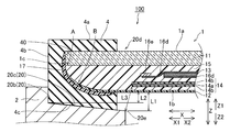
- FIG. 3 is a cross-sectional view of the solar cell module taken along line 200-200 in FIG.
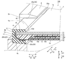
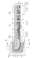
- FIG. 3 is an enlarged cross-sectional view of the solar cell module taken along the line 200-200 in FIG.
- FIG. 3 is a cross-sectional view of the solar cell module taken along line 300-300 in FIG.
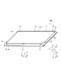
- a solar cell module 100 includes a solar cell panel 1 and a frame 2 for supporting the solar cell panel 1.
- the solar cell panel 1 and the frame body 2 have a substantially rectangular shape including a pair of long sides extending in the X direction and a pair of short sides extending in the Y direction when viewed in plan (in plan view).
- the upper surface 1a of the solar cell panel 1 is formed along a horizontal plane.
- a terminal box 3 for collecting electricity generated in the solar cell panel 1 is disposed on the lower surface 1 b side of the solar cell panel 1 and the X1 side of the solar cell panel 1. And it is arrange
- the frame 2 has a total of 10 locations including the vicinity of both ends of each of the pair of long sides, the vicinity of both ends of each of the pair of short sides, and the vicinity of the center of each of the pair of long sides.
- a draining portion 2a capable of discharging water from the upper surface 1a of the battery panel 1 is provided.
- the water that flows outward from the draining portion 2 a is configured to be discharged to the outside through a groove portion 2 b formed on the outer peripheral surface of the frame body 2.
- the draining portion 2a is an example of the “notched portion” in the present invention.
- the substantially rectangular frame 2 is formed with an accommodating portion 20 including an inner upper surface 20a (see FIG. 5), an inner side surface 20b, and an inner lower surface 20c.
- the cross-sectional shape of the accommodating part 20 is comprised so that it may become a substantially C-shaped recessed part.
- a part of the inner upper surface 20 a and the inner side surface 20 b of the housing portion 20 is not formed.
- the accommodating portion 20 is an example of the “concave portion” in the present invention.
- the inner upper surface 20a of the frame body 2 is formed along a horizontal plane so as to correspond to the upper surface 1a of the solar cell panel 1, and the inner side surface 20b of the frame body 2 is formed along a vertical surface. .
- an opening 20 d into which the solar cell panel 1 is inserted is formed on the solar cell group 30 side (X2 side) described later of the housing portion 20.
- the inner lower surface 20c of the accommodating portion 20 formed in a circumferentially continuous groove shape extends downward (Z2 side) from the lower end of the inner side surface 20b formed on the X2 side to the opening end 20e of the opening 20d of the accommodating portion 20. It is configured to incline toward).
- the distance L1 in the Z direction between the inner lower surface 20c and the lower surface 1b of the solar cell panel 1 at the opening end 20e is larger than the distance L2 in the Z direction between the lower end of the inner surface 20b and the lower surface 1b of the solar cell panel 1.
- the inner lower surface 20c of the housing portion 20 is configured to be inclined downward while maintaining substantially the same inclination angle.
- the frame 2 is made of metal such as Al, so that the inner lower surface 20c of the housing portion 20 is also made of metal.
- a packing 4 made of a resin such as an olefin-based elastomer for filling the space between the solar cell panel 1 and the frame 2 is disposed in the housing portion 20 of the frame 2.
- the packing 4 is formed so that the cross-sectional shape is a substantially C shape having a recess.
- the concave portion of the packing 4 is formed as an accommodating portion 40 in which the solar cell panel 1 is accommodated.
- the solar cell panel 1 is accommodated in the accommodating portion 40 in a state where the solar cell panel 1 and the interface sealing member 17 described later and the accommodating portion 40 are in close contact with each other.
- the packing 4 is an example of the “sealing member” in the present invention.
- the outer upper surface 4 a of the packing 4 is formed along a horizontal plane so as to correspond to the inner upper surface 20 a of the housing portion 20 of the frame body 2. Further, the outer side surface 4 b of the packing 4 is formed along a vertical surface so as to correspond to the inner side surface 20 b of the housing portion 20 of the frame body 2.
- the outer lower surface 4c on the outer side of the packing 4 extends downward from the lower end of the outer surface 4b formed on the X2 side to the end portion on the X1 side so as to correspond to the inclination of the inner lower surface 20c of the housing portion 20 of the frame body 2 ( It is configured to incline toward (Z2 side). Further, the outer lower surface 4c of the packing 4 is configured to be inclined downward while maintaining an inclination angle substantially the same as the inclination of the inner lower surface 20c of the housing portion 20. That is, among the end portions on the X2 side of the packing 4, the thickness t ⁇ b> 1 in the Z direction of the end portion 4 d located below the housing portion 40 (Z2 side) is located above the housing portion 40 (Z1 side). The end portion 4e is configured to be larger than the thickness t2 in the Z direction.
- the solar cell panel 1 includes a surface cover 11 made of water-resistant glass, a weather-resistant back cover 12 made of a resin film such as polyvinyl fluoride (PVF), and a surface cover. 11 and a back cover 12, a plurality of solar cells 13, a protective film 14, and a filler 15 are included.
- the solar cell panel 1 includes a transition tab wiring 16a, a transition tab wiring 16b, a terminal box wiring 16c, and tab wirings 16d and 16e.
- the front cover 11 and the back cover 12 are examples of the “front cover part” and “back cover part” of the present invention, respectively, and the protective film 14 is an example of the “sheet member” of the present invention.
- the filler 15 is an example of the “resin member” in the present invention.
- the filler 15 is made of a resin such as polyvinyl acetate (EVA).
- EVA polyvinyl acetate
- the filler 15 extends over substantially the entire area between the front cover 11 and the rear cover 12, a plurality of solar cells 13, a protective film 14, crossover tab wires 16 a and 16 b, and a terminal box wire 16 c.
- the tab wires 16d and 16e are arranged so as to cover them.
- an interface A is formed between the front cover 11 and the filler 15
- an interface B is formed between the back cover 12 and the filler 15. Both of these interfaces A and B are formed so as to extend to the side end 1c of the solar cell panel 1.
- the side end portion 1 c of the solar cell panel 1 is accommodated in the accommodating portion 20 of the frame body 2 via the interface sealing member 17 and the packing 4.
- the side surface of the front cover 11 is formed so as to extend along the vertical direction (Z direction) at the side end 1c of the solar cell panel 1 and its periphery, while the side surfaces of the filler 15 and the back cover 12 are It is formed on the battery group 30 side (X2 side) and in a gently curved shape that protrudes outward (downward Z2 side).
- the filler 15 is Z1 from the solar cell group 30 side (X2 side) toward the inner side surface 20b side (X1 side) of the housing portion 20. It is formed so as to be inclined gently to the side. That is, the thickness of the filler 15 is configured to decrease from the solar cell group 30 side toward the side end portion 1c side.
- An interfacial sealing member 17 that covers both the interface A between the front cover 11 and the filler 15 and the interface B between the back cover 12 and the filler 15 is disposed at the side end 1c of the solar cell panel 1.
- This interface sealing member 17 is an opening of the accommodating portion 40 of the packing 4 from the height position between the upper surface (upper surface 1a) of the surface cover 11 and the interface A so as to be along the side end portion 1c of the solar cell panel 1. It is formed to extend to the vicinity of.
- the interface sealing member 17 is made of a butyl material or the like, and is applied to the side end portion 1c of the solar cell panel 1 before the solar cell panel 1 is accommodated in the frame 2 (packing 4). It is formed so as to cover A and B.
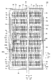
- each of the plurality of solar cells 13 is connected to the back surface of the solar cell 13 adjacent to one of the X directions (X1 side or X2 side) by tab wiring 16d extending in the X direction.
- the back surfaces of the plurality of solar cells 13 are connected to the surface of the solar cell 13 adjacent to the other (X2 side or X1 side) in the X direction by tab wiring 16d extending in the X direction. That is, the plurality of solar cells 13 are connected in series in the X direction by the tab wiring 16d.
- a solar cell group 30 including a plurality of solar cells 13 is formed.
- the solar cell group 30 is connected to the solar cell group 30 adjacent to one of the Y directions (Y1 side or Y2 side) by a crossover tab wiring 16a on the X1 side extending in the Y direction.
- the solar cell group 30 is connected to the solar cell group 30 adjacent to the other side (Y2 side or Y1 side) in the Y direction by an X2 side transition tab wiring 16b extending in the Y direction.
- the X2 side is connected to the solar cell group 30 adjacent in the Y direction, while the X1 side is connected to the solar cell group 30 adjacent in the Y direction.
- the X1 side end portions of the tab wiring 16d of the solar cell group 30 are connected to each other by the X1 side tab wiring 16e extending in the Y direction. Yes.
- the protective film 14 has a substantially rectangular shape composed of a pair of long sides extending in the X direction and a pair of short sides extending in the Y direction.
- Each of a pair of long side of the protective film 14 is provided so that it may be located in the outer side rather than the outer side of the Y direction in the solar cell 13 (solar cell group 30) located in the both ends of the Y direction.
- each of the pair of short sides of the protective film 14 is provided so as to be located further outside the outer side in the X direction in the cross tab wires 16a and 16b and the tab wire 16e located at the end in the X direction. It has been.
- the protective film 14 is provided so as to cover the plurality of solar cells 13, the transition tab wirings 16 a and 16 b, and the tab wiring 16 e when viewed in a plan view. Accordingly, moisture from below the solar cell panel 1 (Z2 side (see FIGS. 3 to 5)) reaches the solar cell 13, the transition tab wires 16a and 16b, and the tab wire 16e by the protective film 14. Can be suppressed.
- the protective film 14 includes a metal layer 14a made of a metal foil such as an Al foil, PVF, PET (polyethylene terephthalate), and the like disposed on the upper and lower surfaces of the metal layer 14a, respectively. And a pair of insulating sheets 14b made of a resin sheet.
- the protective film 14 is configured to prevent moisture that has entered from the outside from passing through the metal layer 14a to the solar cell 13 side. That is, the protective film 14 has weather resistance.
- the protective film 14 is below (Z2 side) below the plurality of solar cells 13, the tab wiring 16d, the transition tab wirings 16a and 16b, and the tab wiring 16e, and above the back cover 12 (Z1 side). It is arranged in a state covered with the filler 15.
- the pair of long sides and the pair of short sides of the protective film 14 are distance L3 from the opening end 20e of the opening 20d of the frame 2 to the solar cell group 30 side (X2 side) through the back cover 12 and the filler 15. It is arranged at a position separated only by. As shown in FIG. 2, the protective film 14 is positioned on the inner side of the opening end 20 e of the frame body 2, and more than the plurality of solar cells 13, the transition tab wirings 16 a and 16 b, and the tab wiring 16 e. It is arranged to be located outside.
- the protective film 14 has a substantially rectangular opening 14c in a plan view at a position corresponding to the position where the terminal box 3 is disposed.
- the back cover 12 has a slit 12a at a position corresponding to the position where the terminal box 3 is arranged and at a position corresponding to the opening 14c. Both the opening 14c and the slit 12a are provided to allow the plurality of terminal box wires 16c to pass therethrough.
- the opening 14c is formed to have an opening area sufficient for the plurality of terminal box wirings 16c to pass therethrough, while the slit 12a is the minimum for the plurality of terminal box wirings 16c to pass therethrough. It is formed to have a limited opening area.
- the opening area of the slit 12a is smaller than the opening area of the opening 14c. Thereby, it is possible to suppress moisture from entering the solar cell panel 1 through the slit 12a.
- the opening 14c and the slit 12a are examples of the “first hole” and the “second hole” in the present invention, respectively.
- the three crossover tab wirings 16a and the pair of tab wirings 16e respectively disposed at both ends in the Y direction are separated by a predetermined distance on the same straight line extending in the Y direction on the X1 side.
- the four transition tab wires 16b are arranged on the same line extending in the Y direction at a predetermined distance on the X2 side.
- the plurality of transition tab wirings 16a and tab wirings 16e and tab wirings 16e and tab wirings 16e or the plurality of transition tab wirings 16b extending in the Y direction are arranged in the X direction.
- transition tab wiring 16a and the tab wiring 16e are examples of the “first wiring” in the present invention.
- each of the plurality of terminal box wires 16c is connected to each of the plurality of transition tab wires 16a and the pair of tab wires 16e arranged on the X1 side, and the other end of the plurality of terminal box wires 16c.
- the end is connected to the terminal box 3 fixed to the lower surface 1b side of the solar cell panel 1.
- the terminal box wiring 16c is an example of the “second wiring” in the present invention.
- the terminal box wiring 16c is located below (Z2 side) from the cross tab wiring 16a on the X1 side. Then, the solar cell 13 adjacent to the crossover tab wiring 16a and the upper part of the protective film 14 are arranged to extend toward the X2 side.
- An insulating sheet (not shown) is disposed between the terminal box wiring 16c and the solar cell 13, and is configured to ensure insulation between the terminal box wiring 16c and the solar cell 13.
- the terminal box wiring 16c is arranged so as to extend toward the Y2 side by bending at a substantially right angle after extending to the predetermined distance X2 side. Thereafter, the terminal box wiring 16c is arranged to extend below the Y2 side solar cell 13 and above the protective film 14 toward the Y2 side.
- the terminal box wiring 16c is arranged so as to extend toward the predetermined distance Y2 and then bend substantially at a right angle to extend toward the X2 side again. Thereafter, the terminal box wiring 16c extends to the opening 14c of the protective film 14, then extends downward (Z2 side), passes through the opening 14c and the slit 12a, and is disposed on the lower surface 1b of the solar cell panel 1.
- the terminal box 3 is arranged so as to be connected. As a result, the terminal box wiring 16c is disposed below the solar cell 13 and above the protective film 14, and the X1 side cross tab wiring 16a and the terminal box 3 are connected to the opening 14c and the slit 12a. It is comprised so that it may connect via.
- the inner lower surface 20c of the accommodating portion 20 of the frame body 2 made of Al is extended from the lower end of the inner side surface 20b formed on the X2 side to the opening end 20e of the opening 20d of the accommodating portion 20.
- the protective film 14 having the metal layer 14a and the housing are accommodated by inclining downward while maintaining substantially the same inclination angle. Since the distance L3 with the inner lower surface 20c of the portion 20 can be increased, the insulation between the metal layer 14a of the protective film 14 and the frame 2 is sufficiently achieved even when the insulating performance of the protective film 14 is deteriorated. Can be secured.
- the pair of long sides and the pair of short sides of the protective film 14 are positioned on the solar cell group 30 side (X2 side) that is a distance L3 away from the opening end 20e of the opening 20d of the frame,
- the protective film 14 and the housing part 20 are inclined.
- the distance L3 from the inner lower surface 20c can be further increased.
- the inner lower surface 20c of the accommodating part 20 closest to the protective film 14 is inclined downward, the distance L3 between the protective film 14 and the opening end 20e of the accommodating part 20 can be reliably increased. As a result, the insulation between the metal layer 14a of the protective film 14 and the accommodating portion 20 can be more sufficiently ensured.
- the protective film 14 And the inner lower surface 20c can be easily increased in distance L3.
- the inner lower surface 20c is inclined downward as compared with the case where the inclination angle of the inner lower surface 20c is locally varied within the surface.
- the frame body 2 having the inner lower surface 20c can be easily formed.
- the protective film 14 is covered with the filler 15.
- the crossover tab wiring 16a positioned above the protective film 14 and the terminal box 3 positioned below the protective film 14 can be easily connected to the terminal box wiring 16c through the opening 14c.
- the opening part 14c can be protected by the filler 15 arrange
- the opening 14c and the slit 12a are formed by forming the slit 12a at a position corresponding to the position where the terminal box 3 of the back cover 12 is disposed and at a position corresponding to the opening 14c.
- the transition tab wiring 16a positioned above the protective film 14 and the terminal box 3 positioned below the protective film 14 can be easily connected to the terminal box wiring 16c.
- the terminal box wiring 16c is disposed below the solar cell 13 and above the protective film 14, and the transition tab wiring 16a on the X1 side and the terminal box 3 are opened.
- the terminal box wiring 16c can be protected by the surface cover 11 and the solar cell 13 from above, and the terminal box wiring 16c can be protected by the protective film 14 from below. Therefore, the terminal box wiring 16c can be extended from the transition tab wiring 16a to the terminal box 3 in a state where the terminal box wiring 16c is reliably protected from the external environment.
- the outer lower surface 4c on the outer side of the packing 4 is the end on the X1 side from the lower end of the outer surface 4b formed on the X2 side so as to correspond to the inner lower surface 20c of the accommodating portion 20 of the frame body 2. Since the inner lower surface 20c of the housing portion 20 of the frame 2 and the outer lower surface 4c of the packing 4 can be brought into close contact with each other by inclining downward to the portion, the protective film 14 and the inner lower surface 20c of the housing portion 20 The solar cell panel 1 can be reliably held in a state where the distance L3 is maintained.
- the end portion on the X2 side of the packing 4 is configured to be positioned closer to the inner side surface 20b side (X1 side) of the accommodating portion 20 than the opening end 20e of the opening 20d of the frame body 2 is protected.
- the solar cell group 30 in which a pair of long sides and a pair of short sides of the film 14 are separated by a distance L3 from the opening end 20e of the opening 20d of the frame 2 through the back cover 12 and the filler 15 without the packing 4 interposed therebetween.
- the interface sealing member which covers both the interface A between the front cover 11 and the filler 15 and the interface B between the back cover 12 and the filler 15 on the side end 1 c of the solar cell panel 1. 17, not only the packing 4 disposed in the accommodating portion 20 of the frame 2 but also the interface sealing member 17, the filler 15 and the surface cover 11 at the side end portion 1 c of the solar cell panel 1.
- the interface A can be covered, and the interface B between the back cover 12 and the filler 15 can be covered.
- the reliability of insulation is reduced due to moisture that has entered the interface A between the filler 15 and the front cover 11 and the interface B between the back cover 12 and the filler 15 at the side end 1c of the solar cell panel 1. It can be suppressed more.
- it can suppress that the surface cover 11 and the filler 15 peel from the side edge part 1c of the solar cell panel 1, and can suppress that the back surface cover 12 and the filler 15 peel. it can.
- the interface sealing member 17 is disposed so as to cover the interfaces A and B in a state where the interface sealing member 17 is covered with the packing 4 in the accommodating portion 40 of the packing 4. Since the sealing member 17 can be protected, it is possible to further prevent moisture from entering the interfaces A and B. Moreover, it can suppress more that the surface cover 11 and the filler 15 peel, and that the back surface cover 12 and the filler 15 peel.
- the end portion located on the upper side of the housing portion 40 is the thickness t1 in the Z direction of the end portion 4d located on the lower side of the housing portion 40.
- the thickness of the filler 15 is reduced from the X2 side toward the X1 side at the side end portion 1c of the solar cell panel 1 accommodated in the accommodating portion 20 of the frame body 2 and its periphery.
- the side edge part 1c of the solar cell panel 1 and its periphery can be easily accommodated in the accommodating part 40 of the packing 4.
- solar cells are provided in the vicinity of both ends of each of the pair of long sides of the frame 2, in the vicinity of both ends of each of the pair of short sides, and in the vicinity of the center of each of the pair of long sides.
- the inner lower surface 20c of the housing part 20 of the frame body 2 is inclined downward in substantially the entire region from the lower end of the inner side surface 20b formed on the X2 side to the opening 20d of the housing part 20.
- the present invention is not limited to this. In this invention, it is not necessary to incline over the whole inner lower surface of the accommodating part of a frame. For example, only the inner lower surface in the vicinity of the opening of the housing portion may be inclined downward. Moreover, it is not necessary to incline the inner lower surface of the housing part while maintaining substantially the same angle, and the inner lower surface of the housing part may be made to have different inclination angles in arbitrary regions.
- the protective film 14 while arrange
- positioned the filler 15 was shown, this invention is not limited to this.
- a filler may not be disposed so as to cover the protective film, and a back cover may not be provided separately. That is, you may comprise so that a protective film may serve as the back surface cover of a solar cell panel. At this time, since moisture easily enters the solar cell panel through the opening of the protective film, it is preferable that the protective film is provided with a slit instead of the opening.
- the solar cell 13 which has an electrode on both surfaces of a surface and a back surface was used, not only this but a back junction type solar cell etc. can be used.
- the said embodiment showed the example which has arrange
- packing silicon resin or the like may be disposed in the housing portion of the frame.
- the length in the X direction of the outer lower surface 4c of the packing 4 is shortened so that the packing 4 used in the above embodiment is not positioned on a straight line connecting the protective film 14 and the opening end 20e of the frame 2.
- the present invention is not limited to this.
- the length in the X direction of the outer lower surface 4c of the packing 4 may be increased so that the packing 4 is positioned on a straight line connecting the protective film 14 and the opening end 20e of the frame 2.
- the interface sealing member which covers both the interface A of the surface cover 11 and the filler 15 and the interface B of the back cover 12 and the filler 15 in the side edge part 1c of the solar cell panel 1 is shown.
- positioned 17 separately from the packing 4 (sealing member) was shown, this invention is not limited to this. In this invention, it is not necessary to provide an interface sealing member in the side edge part of a solar cell panel. Moreover, you may arrange
- the protective film 14 as a "sheet member" of the present invention is a metal layer 14a made of a metal foil such as an Al foil, and PVF, PET, etc. respectively disposed on the front and back surfaces of the metal layer 14a.
- a metal foil such as an Al foil, and PVF, PET, etc.
- this invention is not limited to this. In this invention, you may comprise so that the protective film as a sheet
- seat member may consist only of a metal layer.
- the metal layer of the protective film may be made of a metal foil such as Zn or Fe
- the insulating sheet may be made of a resin sheet such as PPS (polyphenylene sulfide).
- the interface sealing member 17 is apply
- the present invention is not limited to this. In this invention, it is not restricted to the case where an interface sealing member is formed by application
Landscapes
- Photovoltaic Devices (AREA)
Abstract
この太陽電池モジュールは、複数の太陽電池からなる太陽電池群と、金属層を有し、太陽電池群の下方に配置されたシート部材とを含む太陽電池パネルと、太陽電池パネルの側端部が収容される収容部を含む枠体とを備え、枠体の収容部の内側下面は、少なくとも太陽電池群側に向かって下方に傾斜する面を有する。
Description
本発明は、太陽電池モジュールに関し、特に、枠体の収容部に太陽電池パネルの側端部が収容される太陽電池モジュールに関する。
従来、枠体の収容部に太陽電池パネルの側端部が収容される太陽電池モジュールが知られている。このような太陽電池モジュールは、たとえば、特開2003-282900号公報(特許文献1)に開示されている。
特許文献1には、ガラス板と合成樹脂シートとの間に、封止樹脂によって覆われた太陽電池セルおよび保護フィルム(シート部材)が配置された太陽電池パネルと、太陽電池パネルの側端部が収容される凹部が形成された枠体とを備える太陽電池モジュールが開示されている。特許文献1に記載の太陽電池パネルの保護フィルムは、Al箔をPVF(ポリフッ化ビニル)からなる耐候性シートで上下両面から挟み込むようにして形成されている。また、枠体は金属製であるとともに、凹部の内側下面は水平面状に形成されている。
しかしながら、特許文献1に開示された太陽電池モジュールでは、枠体の凹部の内側下面が水平面状になるように構成されているため、凹部の内側下面と保護フィルムとの距離が比較的近い。このため、保護フィルムのAl箔と金属製の枠体との絶縁を確保するために、保護フィルムの耐候性シートとして長期間絶縁性能が低下しにくい材質のものを選択するなどの工夫が必要とされていた。
この発明は、上記のような課題を解決するためになされたものであり、この発明の1つの目的は、容易に絶縁に関する信頼性を向上させることができる太陽電池モジュールを提供することである。
上記目的を達成するために、この発明に係る太陽電池モジュールは、複数の太陽電池からなる太陽電池群と、金属層を有し、太陽電池群の下方に配置されたシート部材とを含む太陽電池パネルと、太陽電池パネルの側端部が収容される収容部を含む枠体とを備え、枠体の収容部の内側下面は、少なくとも太陽電池群側に向かって下方に傾斜する面を有する。
上記の太陽電池モジュールでは、枠体の収容部の内側下面が、少なくとも太陽電池群側に向かって下方に傾斜する面を有することによって、枠体の収容部の内側下面が水平面状である場合と比べて、金属層を有するシート部材と収容部の内側下面との距離を大きくすることができるので、シート部材の金属層と枠体との絶縁を十分に確保することができる。
以下、本発明の実施形態を図面に基づいて説明する。
図1および図2に示すように、本発明の一実施形態による太陽電池モジュール100は、太陽電池パネル1と、太陽電池パネル1を支持するための枠体2とを備えている。太陽電池パネル1および枠体2は、平面的に見て(平面視において)、X方向に延びる一対の長辺とY方向に延びる一対の短辺とからなる略長方形形状を有する。また、太陽電池パネル1の上面1aは、水平面に沿って形成されている。また、図2に示すように、太陽電池パネル1において発電された電気を集電するための端子ボックス3が太陽電池パネル1の下面1b側に配置されているとともに、太陽電池パネル1のX1側で、かつ、Y方向の略中央に配置されている。
また、枠体2には、一対の長辺の各々の両端部近傍と、一対の短辺の各々の両端部近傍と、一対の長辺の各々の中央部近傍との計10箇所に、太陽電池パネル1の上面1aから外側に水を排出することが可能な水切り部2aが設けられている。この水切り部2aから外側に流れた水は、枠体2の外周面に形成された溝部2bを介して、外部に排出されるように構成されている。なお、水切り部2aは、本発明の「切り欠き部」の一例である。
また、図3~図5に示すように、略長方形形状の枠体2には、内側上面20a(図5参照)、内側面20bおよび内側下面20cを含む収容部20が形成されている。収容部20の断面形状は、略C字形状の凹部となるように構成されている。なお、図3および図4に示すように、枠体2の水切り部2aが形成されている領域では、収容部20の内側上面20aおよび内側面20bの一部は形成されていない。なお、収容部20は、本発明の「凹部」の一例である。
また、枠体2の内側上面20aは、太陽電池パネル1の上面1aに対応するように水平面に沿って形成されており、枠体2の内側面20bは、鉛直面に沿って形成されている。
ここで、本実施形態では、図4および図5に示すように、収容部20の後述する太陽電池群30側(X2側)には、太陽電池パネル1が挿入される開口20dが形成されている。また、周状に連続する溝状に形成された収容部20の内側下面20cは、X2側に形成された内側面20bの下端から収容部20の開口20dの開口端20eまで、下方(Z2側)に向かって傾斜するように構成されている。すなわち、開口端20eにおける内側下面20cと太陽電池パネル1の下面1bとのZ方向の距離L1は、内側面20bの下端と太陽電池パネル1の下面1bとのZ方向の距離L2よりも大きくなるように構成されている。また、収容部20の内側下面20cは、略同一の傾斜角度を保った状態で下方に傾斜するように構成されている。なお、枠体2は、Alなどの金属からなることによって、収容部20の内側下面20cも金属からなる。
枠体2の収容部20には、太陽電池パネル1と枠体2との間を埋めるためのオレフィン系エラストマなどの樹脂からなるパッキン4が配置されている。このパッキン4は、断面形状が凹部を有する略C字形状となるように形成されている。パッキン4の凹部は、太陽電池パネル1が収容される収容部40として形成されている。この収容部40には、太陽電池パネル1および後述する界面封止部材17と、収容部40とが密着した状態で、太陽電池パネル1が収容されている。なお、パッキン4は、本発明の「封止部材」の一例である。
図5に示すように、パッキン4の外側上面4aは、枠体2の収容部20の内側上面20aに対応するように、水平面に沿って形成されている。また、パッキン4の外側面4bは、枠体2の収容部20の内側面20bに対応するように、鉛直面に沿って形成されている。
パッキン4の外側の外側下面4cは、枠体2の収容部20の内側下面20cにおける傾斜に対応するように、X2側に形成された外側面4bの下端からX1側の端部まで、下方(Z2側)に向かって傾斜するように構成されている。また、パッキン4の外側下面4cは、収容部20の内側下面20cにおける傾斜と略同一の傾斜角度を保った状態で下方に傾斜するように構成されている。つまり、パッキン4のX2側の端部のうち、収容部40よりも下側(Z2側)に位置する端部4dのZ方向の厚みt1は、収容部40よりも上側(Z1側)に位置する端部4eのZ方向の厚みt2よりも大きくなるように構成されている。
図3~図5に示すように、太陽電池パネル1は、耐水性を有するガラスからなる表面カバー11と、ポリフッ化ビニル(PVF)などの樹脂フィルムからなる耐候性の裏面カバー12と、表面カバー11と裏面カバー12との間に配置される複数の太陽電池13、保護フィルム14および充填材15とを含む。また、図2に示すように、太陽電池パネル1は、渡りタブ配線16aと、渡りタブ配線16bと、端子ボックス用配線16cと、タブ配線16dおよび16eとを含む。なお、表面カバー11および裏面カバー12は、それぞれ、本発明の「表面カバー部」および「裏面カバー部」の一例であり、保護フィルム14は、本発明の「シート部材」の一例である。また、充填材15は、本発明の「樹脂部材」の一例である。
図3~図5に示すように、充填材15は、ポリ酢酸ビニル(EVA)などの樹脂からなる。また、充填材15は、表面カバー11と裏面カバー12との間の略全体に渡って、複数の太陽電池13と、保護フィルム14と、渡りタブ配線16aおよび16bと、端子ボックス用配線16cと、タブ配線16dおよび16eとを覆うように配置されている。これにより、表面カバー11と充填材15との間には界面Aが形成されているとともに、裏面カバー12と充填材15との間には界面Bが形成されている。これら界面AおよびBは、共に、太陽電池パネル1の側端部1cまで延びるように形成されている。太陽電池パネル1の側端部1cは、界面封止部材17とパッキン4とを介して枠体2の収容部20に収容されている。
太陽電池パネル1の側端部1cおよびその周辺において、表面カバー11の側面は鉛直方向(Z方向)に沿って延びるように形成されている一方、充填材15および裏面カバー12の側面は、太陽電池群30側(X2側)で、かつ、下方(Z2側)に向かって外側に凸の緩やかな曲面状に形成されている。具体的には、太陽電池パネル1の側端部1cおよびその周辺において、充填材15が、太陽電池群30側(X2側)から収容部20の内側面20b側(X1側)に向かってZ1側になだらかに傾斜するように形成されている。つまり、充填材15の厚みは、太陽電池群30側から側端部1c側に向かって小さくなるように構成されている。
また、太陽電池パネル1の側端部1cには、表面カバー11と充填材15との界面Aと、裏面カバー12と充填材15との界面Bと、を共に覆う界面封止部材17が配置されている。この界面封止部材17は、表面カバー11の上面(上面1a)と界面Aとの間の高さ位置から、太陽電池パネル1の側端部1cに沿うようにパッキン4の収容部40の開口の近傍まで延びるように形成されている。なお、界面封止部材17はブチル系の材料などからなり、太陽電池パネル1を枠体2(パッキン4)に収容する前に、太陽電池パネル1の側端部1cに塗布されることによって界面AおよびBを覆うように形成されている。
図2に示すように、複数の太陽電池13の表面は、各々、X方向に延びるタブ配線16dによって、X方向のいずれか一方(X1側またはX2側)に隣接する太陽電池13の裏面と接続されている。また、複数の太陽電池13の裏面は、各々、X方向に延びるタブ配線16dによって、X方向のいずれか他方(X2側またはX1側)に隣接する太陽電池13の表面と接続されている。すなわち、複数の太陽電池13は、タブ配線16dによって、X方向に直列に接続されている。これにより、複数の太陽電池13からなる太陽電池群30が形成されている。
X方向に接続された太陽電池群30は、Y方向に並ぶように8つ配置されている。太陽電池群30は、Y方向に延びるX1側の渡りタブ配線16aによって、Y方向のいずれか一方(Y1側またはY2側)に隣接する太陽電池群30と接続されている。また、太陽電池群30は、Y方向に延びるX2側の渡りタブ配線16bによって、Y方向のいずれか他方(Y2側またはY1側)に隣接する太陽電池群30と接続されている。なお、Y方向の両端部に位置する太陽電池群30においては、X2側ではY方向に隣接する太陽電池群30と接続されている一方、X1側ではY方向に隣接する太陽電池群30と接続されていない。なお、Y方向の両端部に位置する太陽電池群30のX1側では、Y方向に延びるX1側のタブ配線16eによって、太陽電池群30のタブ配線16dのX1側の端部同士が接続されている。
保護フィルム14は、X方向に延びる一対の長辺とY方向に延びる一対の短辺とからなる略長方形形状を有している。保護フィルム14の一対の長辺の各々は、Y方向の両端部に位置する太陽電池13(太陽電池群30)におけるY方向の外側の辺よりもさらに外側に位置するように設けられている。また、保護フィルム14の一対の短辺の各々は、X方向の端部に位置する渡りタブ配線16aおよび16bとタブ配線16eとにおけるX方向の外側の辺よりもさらに外側に位置するように設けられている。すなわち、保護フィルム14は、平面的に見て、複数の太陽電池13と、渡りタブ配線16aおよび16bと、タブ配線16eとを覆うように設けられている。これにより、保護フィルム14によって、太陽電池パネル1の下方(Z2側(図3~図5参照))からの水分が太陽電池13と、渡りタブ配線16aおよび16bと、タブ配線16eとに到達するのを抑制することが可能である。
また、保護フィルム14は、図4および図5に示すように、Al箔などの金属箔からなる金属層14aと、金属層14aの上面および下面にそれぞれ配置されたPVFやPET(ポリエチレンテレフタレート)などの樹脂シートからなる一対の絶縁シート14bとから構成されている。保護フィルム14は、金属層14aによって、外部から浸入した水分を太陽電池13側に透過させないように構成されている。すなわち、保護フィルム14は、耐候性を有する。また、保護フィルム14は、複数の太陽電池13と、タブ配線16dと、渡りタブ配線16aおよび16bと、タブ配線16eとの下方(Z2側)で、かつ、裏面カバー12の上方(Z1側)に充填材15に覆われた状態で配置されている。
保護フィルム14の一対の長辺および一対の短辺は、裏面カバー12と充填材15とを介して、太陽電池群30側(X2側)に枠体2の開口20dの開口端20eから距離L3だけ隔てた位置に配置されている。なお、図2に示すように、保護フィルム14は、枠体2の開口端20eよりも内側に位置するとともに、複数の太陽電池13と、渡りタブ配線16aおよび16bと、タブ配線16eとよりも外側に位置するように配置されている。
また、保護フィルム14は、端子ボックス3が配置される位置に対応する位置に、平面的に見て略長方形形状の開口部14cを有する。また、裏面カバー12は、図5に示すように、端子ボックス3が配置される位置に対応する位置で、かつ、開口部14cに対応する位置に、スリット12aを有する。この開口部14cおよびスリット12aは、共に複数の端子ボックス用配線16cを通過させるために設けられている。なお、開口部14cは、複数の端子ボックス用配線16cが通過するのに十分な開口面積を有するように形成されている一方、スリット12aは、複数の端子ボックス用配線16cが通過するのに最低限の開口面積を有するように形成されている。つまり、スリット12aの開口面積は、開口部14cの開口面積よりも小さい。これにより、スリット12aを介して水分が太陽電池パネル1内に浸入するのを抑制することが可能である。なお、開口部14cおよびスリット12aは、それぞれ、本発明の「第1穴部」および「第2穴部」の一例である。
図2に示すように、3つの渡りタブ配線16aとY方向の両端部にそれぞれ配置された一対のタブ配線16eとは、X1側において、Y方向に延びる同一の直線上に所定の距離を隔てて配置されている。また、4つの渡りタブ配線16bは、X2側において、Y方向に延びる同一の直線上に所定の距離を隔てて配置されている。これにより、Y方向に延びる複数の渡りタブ配線16aおよびタブ配線16eまたは複数の渡りタブ配線16bの各々をX方向に並ぶように配置する場合と比べて、複数の渡りタブ配線16aおよびタブ配線16eまたは複数の渡りタブ配線16bの各々をX方向の端部に配置された太陽電池13に近接する位置に配置することが可能である。この結果、渡りタブ配線16aおよび16bならびにタブ配線16eと太陽電池パネル1の側端部1cとの距離を大きくすることが可能である。なお、渡りタブ配線16aおよびタブ配線16eは、本発明の「第1配線」の一例である。
また、複数の端子ボックス用配線16cの一方端は、X1側に配置された複数の渡りタブ配線16aおよび一対のタブ配線16eの各々と接続されているとともに、複数の端子ボックス用配線16cの他方端は、太陽電池パネル1の下面1b側に固定された端子ボックス3と接続されている。なお、端子ボックス用配線16cは、本発明の「第2配線」の一例である。
たとえば、図2に示す300-300線に沿った位置における端子ボックス用配線16cの場合、図5に示すように、端子ボックス用配線16cは、X1側の渡りタブ配線16aから下方(Z2側)に延びた後、渡りタブ配線16aに隣接する太陽電池13の下方で、かつ、保護フィルム14の上方をX2側に向かって延びるように配置されている。なお、端子ボックス用配線16cと太陽電池13との間には、図示しない絶縁シートが配置されており、端子ボックス用配線16cと太陽電池13との絶縁を確保するように構成されている。
端子ボックス用配線16cは、所定の距離X2側に延びた後、略直角に曲がってY2側に向かって延びるように配置されている。その後、端子ボックス用配線16cは、Y2側の太陽電池13の下方で、かつ、保護フィルム14の上方をY2側に向かって延びるように配置されている。
そして、端子ボックス用配線16cは、所定の距離Y2側に延びた後、略直角に曲がって再度X2側に向かって延びるように配置されている。その後、端子ボックス用配線16cは、保護フィルム14の開口部14cまで延びた後、下方(Z2側)に向かって延び、開口部14cおよびスリット12aを通過して太陽電池パネル1の下面1bに配置された端子ボックス3と接続されるように配置されている。この結果、端子ボックス用配線16cは、太陽電池13の下方で、かつ、保護フィルム14の上方に配置された状態で、X1側の渡りタブ配線16aと端子ボックス3とを開口部14cおよびスリット12aを介して接続するように構成されている。
本実施形態では、上記のように、Alからなる枠体2の収容部20の内側下面20cを、X2側に形成された内側面20bの下端から収容部20の開口20dの開口端20eまで、略同一の傾斜角度を保った状態で下方に向かって傾斜させることによって、枠体2の収容部20の内側下面20cが水平面状である場合と比べて、金属層14aを有する保護フィルム14と収容部20の内側下面20cとの距離L3を大きくすることができるので、保護フィルム14の絶縁性能が低下した場合であっても、保護フィルム14の金属層14aと枠体2との絶縁を十分に確保することができる。
また、本実施形態では、保護フィルム14の一対の長辺および一対の短辺を、枠体の開口20dの開口端20eから距離L3離れた太陽電池群30側(X2側)に位置させるとともに、枠体2の収容部20の内側下面20cを、X2側に形成された内側面20bの下端から収容部20の開口端20eまで、下方に向かって傾斜させることによって、保護フィルム14と収容部20の内側下面20cとの距離L3をより大きくすることができる。また、保護フィルム14に一番近接する収容部20の内側下面20cが下方に傾斜しているので、保護フィルム14と収容部20の開口端20eとの距離L3を確実に大きくすることができる。これらにより、保護フィルム14の金属層14aと収容部20との絶縁をより十分に確保することができる。
また、本実施形態では、内側下面20cを下方に向かって傾斜させることによって、収容部20の開口端20eの高さ位置を容易に下方(Z2側)に位置させることができるので、保護フィルム14と内側下面20cとの距離L3を容易に大きくすることができる。また、内側下面20cを略同一の傾斜角度を保った状態で下方に向かって傾斜させることによって、内側下面20cの傾斜角度を面内で局所的に異ならせる場合よりも、下方に向かって傾斜する内側下面20cを有する枠体2を容易に形成することができる。
また、本実施形態では、保護フィルム14の端子ボックス3が配置される部分に対応する位置に、平面視において略長方形形状の開口部14cを形成するとともに、保護フィルム14を充填材15に覆われた状態で配置することによって、開口部14cを介して、保護フィルム14の上方に位置する渡りタブ配線16aと、保護フィルム14の下方に位置する端子ボックス3とを端子ボックス用配線16cにより容易に接続することができる。また、保護フィルム14を覆うように配置された充填材15によって開口部14cを保護することができるので、開口部14cにおいて保護フィルム14の絶縁性能が低下するのを抑制することができるとともに、開口部14cを介して、水分が太陽電池13と渡りタブ配線16aおよび16bとに到達するのを抑制することができる。
また、本実施形態では、裏面カバー12の端子ボックス3が配置される位置に対応する位置で、かつ、開口部14cに対応する位置に、スリット12aを形成することによって、開口部14cおよびスリット12aを介して、保護フィルム14の上方に位置する渡りタブ配線16aと、保護フィルム14の下方に位置する端子ボックス3とを端子ボックス用配線16cに容易に接続することができる。加えて、本実施形態では、裏面カバー12のスリット12aの開口面積を、保護フィルム14の開口部14cの開口面積よりも小さくすることによって、スリット12aを介して水分が太陽電池パネル1内に浸入するのを抑制することができるとともに、開口部14cにおいて端子ボックス用配線16cと保護フィルム14とが接触することをより抑制することができる。
また、本実施形態では、端子ボックス用配線16cを、太陽電池13の下方で、かつ、保護フィルム14の上方に配置された状態で、X1側の渡りタブ配線16aと端子ボックス3とを開口部14cおよびスリット12aを介して接続することによって、上方から表面カバー11および太陽電池13により端子ボックス用配線16cを保護することができるとともに、下方から保護フィルム14により端子ボックス用配線16cを保護することができるので、端子ボックス用配線16cを外部環境から確実に保護した状態で、渡りタブ配線16aから端子ボックス3まで端子ボックス用配線16cを延ばすことができる。
また、本実施形態では、パッキン4の外側の外側下面4cを、枠体2の収容部20の内側下面20cに対応するように、X2側に形成された外側面4bの下端からX1側の端部まで、下方に向かって傾斜させることによって、枠体2の収容部20の内側下面20cとパッキン4の外側下面4cとを密着させることができるので、保護フィルム14と収容部20の内側下面20cとの距離L3を保った状態で確実に太陽電池パネル1を保持することができる。
また、本実施形態では、パッキン4のX2側の端部が枠体2の開口20dの開口端20eよりも収容部20の内側面20b側(X1側)に位置するように構成するとともに、保護フィルム14の一対の長辺および一対の短辺が、パッキン4を介さずに裏面カバー12と充填材15を介して、枠体2の開口20dの開口端20eから距離L3離れた太陽電池群30側(X2側)に位置するように構成することによって、パッキン4の外部に露出する部分が増加することに起因してパッキン4が劣化しやすくなることを抑制することができる。また、裏面カバー12と充填材15とを介して、保護フィルム14と枠体2の開口端20eとの距離を大きくすることができるので、保護フィルム14の金属層14aと枠体2との絶縁を確実に確保することができる。
また、本実施形態では、太陽電池パネル1の側端部1cに、表面カバー11と充填材15との界面Aと、裏面カバー12と充填材15との界面Bとを共に覆う界面封止部材17を配置することによって、枠体2の収容部20に配置されたパッキン4だけでなく界面封止部材17によっても、太陽電池パネル1の側端部1cにおける充填材15と表面カバー11との界面Aを覆うことができるとともに、裏面カバー12と充填材15との界面Bを覆うことができる。これにより、太陽電池パネル1の側端部1cにおいて充填材15と表面カバー11との界面Aおよび裏面カバー12と充填材15との界面Bに浸入した水分に起因して絶縁に関する信頼性が低下するのをより抑制することができる。また、太陽電池パネル1の側端部1cを起点として、表面カバー11と充填材15とが剥がれるのを抑制することができるとともに、裏面カバー12と充填材15とが剥がれるのを抑制することができる。
また、本実施形態では、界面封止部材17を、パッキン4の収容部40の中でパッキン4に覆われた状態で、界面AおよびBを覆うように配置することによって、パッキン4によって、界面封止部材17を保護することができるので、界面AおよびBに水分が浸入することをより抑制することができる。また、表面カバー11と充填材15とが剥がれることと、裏面カバー12と充填材15とが剥がれることとをより抑制することができる。
また、本実施形態では、パッキン4のX2側の端部のうち、収容部40よりも下側に位置する端部4dのZ方向の厚みt1を、収容部40よりも上側に位置する端部4eのZ方向の厚みt2よりも大きくすることによって、容易に、保護フィルム14と収容部20の内側下面20cとの距離L3を大きくすることができる。
また、本実施形態では、枠体2の収容部20に収容される太陽電池パネル1の側端部1cおよびその周辺において、充填材15の厚みがX2側からX1側に向かって小さくなるように構成することによって、容易に、パッキン4の収容部40に太陽電池パネル1の側端部1cおよびその周辺を収容することができる。
また、本実施形態では、枠体2の一対の長辺の各々の両端部近傍と、一対の短辺の各々の両端部近傍と、一対の長辺の各々の中央部近傍とに、太陽電池パネル1の上面1aから外側に水を排出することが可能な水切り部2aを設けることによって、水切り部2aを介して、太陽電池パネル1の上面1aに溜まった水を外部に排出することができるので、受光面(上面1a)に汚れがたまることにより性能が低下するのをより抑制することができる。
なお、今回開示された実施形態は、すべての点で例示であって制限的なものではないと考えられるべきである。本発明の範囲は、上記した実施形態の説明ではなく特許請求の範囲によって示され、さらに特許請求の範囲と均等の意味および範囲内でのすべての変更が含まれる。
たとえば、上記実施形態では、枠体2の収容部20の内側下面20cを、X2側に形成された内側面20bの下端から収容部20の開口20dまで、略全領域で下方に向かって傾斜させた例を示したが、本発明はこれに限られない。本発明では、枠体の収容部の内側下面の全体に渡って傾斜させなくてもよい。たとえば、収容部の開口部近傍の内側下面だけ下方に傾斜させてもよい。また、収容部の内側下面を略同一の角度を保った状態で傾斜させる必要はなく、収容部の内側下面を傾斜の角度を任意の領域で異ならせてもよい。
また、上記実施形態では、保護フィルム14を、複数の太陽電池13と渡りタブ配線16aおよび16bとタブ配線16eとの下方で、かつ、裏面カバー12の上方に配置するとともに、保護フィルム14を覆うように充填材15を配置した例を示したが、本発明はこれに限られない。本発明では、保護フィルムを覆うように充填材を配置しなくてもよいし、裏面カバーを別途設けなくてもよい。すなわち、保護フィルムが太陽電池パネルの裏面カバーを兼ねるように構成してもよい。この際、保護フィルムの開口部を介して水分が太陽電池パネルに浸入しやすいため、保護フィルムには開口部ではなくスリットを設けるのが好ましい。加えて、上記実施形態では、表面と裏面の両面に電極を有する太陽電池13を用いたが、これに限らず裏面接合型の太陽電池等を用いることができる。
また、上記実施形態では、枠体2の収容部20に、太陽電池パネル1と枠体2との間を埋めるためのパッキン4(封止部材)を配置した例を示したが、本発明はこれに限られない。たとえば、パッキンの代わりにシリコン樹脂などを枠体の収容部に配置してもよい。
加えて、上記実施形態で用いたパッキン4が保護フィルム14と枠体2の開口端20eとを結ぶ直線上には位置しないように、パッキン4の外側下面4cのX方向の長さを短くして構成している例を示したが、本発明はこれに限られない。たとえば、パッキン4が保護フィルム14と枠体2の開口端20eとを結ぶ直線上に位置するように、パッキン4の外側下面4cのX方向の長さを長くしてもよい。
また、上記実施形態では、太陽電池パネル1の側端部1cに、表面カバー11と充填材15との界面Aと、裏面カバー12と充填材15との界面Bとを共に覆う界面封止部材17を、パッキン4(封止部材)とは別途配置した例を示したが、本発明はこれに限られない。本発明では、太陽電池パネルの側端部に界面封止部材を設けなくてもよい。また、界面封止部材を界面Aまたは界面Bのいずれか一方のみを覆うように配置してもよい。
また、上記実施形態では、本発明の「シート部材」としての保護フィルム14を、Al箔などの金属箔からなる金属層14aと、金属層14aの表面および裏面にそれぞれ配置されたPVFやPETなどの樹脂シートからなる一対の絶縁シート14bとから構成した例を示したが、本発明はこれに限られない。本発明では、シート部材としての保護フィルムを金属層のみからなるように構成してもよい。また、保護フィルムの金属層をZnやFeなどの金属箔からなるように構成してもよいし、絶縁シートをPPS(ポリフェニレンスルファイド)などの樹脂シートからなるように構成してもよい。
また、上記実施形態では、界面封止部材17を、太陽電池パネル1を枠体2(パッキン4)に収容する前に、太陽電池パネル1の側端部1cに塗布することによって界面AおよびBを覆うように形成した例を示したが、本発明はこれに限られない。本発明では、界面封止部材を塗布によって形成する場合に限られず、たとえば、テープ状の界面封止部材を界面AおよびBを覆うように配置してもよい。
Claims (18)
- 複数の太陽電池からなる太陽電池群と、金属層を有し、前記太陽電池群の下方に配置されたシート部材とを含む太陽電池パネルと、
前記太陽電池パネルの側端部が収容される収容部を含む枠体とを備え、
前記枠体の収容部の内側下面は、少なくとも前記太陽電池群側に向かって下方に傾斜する面を有する、太陽電池モジュール。 - 前記収容部は、前記太陽電池群側に開口する凹部を含み、
前記シート部材の前記収容部側の側端部は、前記収容部の凹部の開口端よりも前記太陽電池群側に位置しているとともに、前記収容部の凹部の内側下面は、少なくとも前記凹部の開口端周辺において下方に傾斜している、請求項1に記載の太陽電池モジュール。 - 前記収容部の凹部の内側下面は、前記凹部の開口端とは反対側の端部から前記凹部の開口端に向かって略全域で下方に傾斜している、請求項2に記載の太陽電池モジュール。
- 前記収容部の凹部の内側下面は、前記凹部の開口端とは反対側の端部から前記凹部の開口端に向かって略同一の傾斜角度で下方に傾斜している、請求項3に記載の太陽電池モジュール。
- 前記枠体は、平面視において矩形状に形成されており、
前記収容部の凹部は、前記矩形状の枠体の内周面に沿って連続する溝状に形成されており、
前記連続する溝状の凹部の内側下面は、前記矩形状の枠体の内側に向かって下方に傾斜する面を有する、請求項2に記載の太陽電池モジュール。 - 前記太陽電池パネルの下方に配置された端子ボックスをさらに備え、
前記太陽電池パネルは、少なくとも前記シート部材を挟み込むように配置された樹脂部材と、前記シート部材の上方で前記太陽電池群に接続された第1配線と、前記端子ボックスと前記第1配線とを接続する第2配線とをさらに含み、
前記シート部材は、前記第1配線と前記端子ボックスとを前記第2配線によって接続するための開口部を有する、請求項1に記載の太陽電池モジュール。 - 前記シート部材の開口部は、前記端子ボックスが配置される位置に対応する位置に形成された第1穴部を有する、請求項6に記載の太陽電池モジュール。
- 前記太陽電池パネルは、前記樹脂部材の裏面上に配置された裏面カバー部をさらに含み、
前記裏面カバー部は、前記シート部材の第1穴部に対応する位置に形成され、前記第1配線と前記端子ボックスとを前記第2配線によって接続するための第2穴部を有する、請求項7に記載の太陽電池モジュール。 - 前記裏面カバー部の第2穴部の開口面積は、前記シート部材の第1穴部の開口面積よりも小さい、請求項8に記載の太陽電池モジュール。
- 前記第2配線は、前記複数の太陽電池の下方で、かつ、前記シート部材の上方を通るように、前記第1配線との接続部分から前記シート部材の第1穴部まで延びているとともに、前記第1穴部および前記第2穴部を介して前記端子ボックスに接続されている、請求項8に記載の太陽電池モジュール。
- 前記太陽電池パネルと前記枠体との間を埋めるように前記枠体の収容部に配置された封止部材をさらに備え、
前記封止部材の外側下面は、前記太陽電池群側に向かって下方に傾斜する前記収容部の内側下面の面に対応するように前記太陽電池群側に向かって下方に傾斜する面を有する、請求項1に記載の太陽電池モジュール。 - 前記封止部材の前記太陽電池群側の端部は、前記収容部の内側下面の前記太陽電池群側の端部よりも前記太陽電池群とは反対側に位置するように構成されており、
前記太陽電池パネルは、少なくとも前記シート部材を挟み込むように配置された樹脂部材と、前記樹脂部材の裏面上に配置された裏面カバー部とをさらに含み、
前記シート部材の前記収容部側の側端部と前記収容部の内側下面の前記太陽電池群側の端部とは、前記封止部材を介さずに前記樹脂部材と前記裏面カバー部とを介して配置されている、請求項11に記載の太陽電池モジュール。 - 前記太陽電池パネルと前記枠体との間を埋めるように前記枠体の収容部に配置された封止部材をさらに備え、
前記太陽電池パネルは、前記シート部材を挟み込むように配置されるとともに、前記太陽電池群が埋め込まれる樹脂部材と、前記樹脂部材の表面上に配置された表面カバー部と、前記封止部材の内側に位置するとともに、前記封止部材とは別個に設けられた界面封止部材とをさらに含み、
前記界面封止部材は、前記太陽電池パネルの側端部における前記樹脂部材と前記表面カバー部との界面を少なくとも覆うように配置されている、請求項1に記載の太陽電池モジュール。 - 前記太陽電池パネルは、前記樹脂部材の裏面上に配置された裏面カバー部をさらに含み、
前記界面封止部材は、前記封止部材の内側において、前記太陽電池パネルの側端部における前記樹脂部材と前記表面カバー部との界面と、前記太陽電池パネルの側端部における前記樹脂部材と前記裏面カバー部との界面とを覆うように配置されている、請求項13に記載の太陽電池モジュール。 - 前記封止部材は、前記界面封止部材を覆うように配置されている、請求項13に記載の太陽電池モジュール。
- 前記太陽電池パネルと前記枠体との間を埋めるように前記枠体の収容部に配置された封止部材をさらに備え、
前記封止部材の前記太陽電池群側の下端部の厚みは、前記封止部材の前記太陽電池群側の上端部の厚みよりも大きくなるように構成されている、請求項1に記載の太陽電池モジュール。 - 前記太陽電池パネルは、前記シート部材を挟み込むように配置されるとともに、前記太陽電池群が埋め込まれる樹脂部材をさらに含み、
前記収容部に収容される部分において、前記樹脂部材の厚みは、前記太陽電池パネルの側端部に向かって小さくなるように構成されている、請求項1に記載の太陽電池モジュール。 - 前記枠体は、前記太陽電池パネルの上面から水を外部に排出するための切り欠き部を含む、請求項1に記載の太陽電池モジュール。
Applications Claiming Priority (2)
| Application Number | Priority Date | Filing Date | Title |
|---|---|---|---|
| JP2010-168357 | 2010-07-27 | ||
| JP2010168357 | 2010-07-27 |
Publications (1)
| Publication Number | Publication Date |
|---|---|
| WO2012014922A1 true WO2012014922A1 (ja) | 2012-02-02 |
Family
ID=45530126
Family Applications (1)
| Application Number | Title | Priority Date | Filing Date |
|---|---|---|---|
| PCT/JP2011/067064 Ceased WO2012014922A1 (ja) | 2010-07-27 | 2011-07-27 | 太陽電池モジュール |
Country Status (1)
| Country | Link |
|---|---|
| WO (1) | WO2012014922A1 (ja) |
Cited By (7)
| Publication number | Priority date | Publication date | Assignee | Title |
|---|---|---|---|---|
| WO2013121549A1 (ja) * | 2012-02-16 | 2013-08-22 | 三洋電機株式会社 | 太陽電池モジュール及びその製造方法 |
| WO2013132602A1 (ja) * | 2012-03-07 | 2013-09-12 | 三洋電機株式会社 | 太陽電池モジュール |
| JP2015090967A (ja) * | 2013-11-07 | 2015-05-11 | シャープ株式会社 | 太陽電池モジュール |
| JPWO2013132602A1 (ja) * | 2012-03-07 | 2015-07-30 | パナソニックIpマネジメント株式会社 | 太陽電池モジュール |
| JP2016103661A (ja) * | 2016-02-19 | 2016-06-02 | パナソニックIpマネジメント株式会社 | 太陽電池モジュール |
| JP2016123177A (ja) * | 2014-12-24 | 2016-07-07 | シャープ株式会社 | 太陽電池モジュール |
| JP2016123176A (ja) * | 2014-12-24 | 2016-07-07 | シャープ株式会社 | 太陽電池モジュール |
Citations (3)
| Publication number | Priority date | Publication date | Assignee | Title |
|---|---|---|---|---|
| JP2003078154A (ja) * | 2001-09-06 | 2003-03-14 | Mitsubishi Heavy Ind Ltd | 太陽電池モジュール枠の取り合い構造 |
| JP2003282900A (ja) * | 2002-03-25 | 2003-10-03 | Sanyo Electric Co Ltd | 太陽電池モジュール |
| JP2008147382A (ja) * | 2006-12-08 | 2008-06-26 | Honda Motor Co Ltd | 太陽電池モジュール及びその製造方法 |
-
2011
- 2011-07-27 WO PCT/JP2011/067064 patent/WO2012014922A1/ja not_active Ceased
Patent Citations (3)
| Publication number | Priority date | Publication date | Assignee | Title |
|---|---|---|---|---|
| JP2003078154A (ja) * | 2001-09-06 | 2003-03-14 | Mitsubishi Heavy Ind Ltd | 太陽電池モジュール枠の取り合い構造 |
| JP2003282900A (ja) * | 2002-03-25 | 2003-10-03 | Sanyo Electric Co Ltd | 太陽電池モジュール |
| JP2008147382A (ja) * | 2006-12-08 | 2008-06-26 | Honda Motor Co Ltd | 太陽電池モジュール及びその製造方法 |
Cited By (11)
| Publication number | Priority date | Publication date | Assignee | Title |
|---|---|---|---|---|
| WO2013121549A1 (ja) * | 2012-02-16 | 2013-08-22 | 三洋電機株式会社 | 太陽電池モジュール及びその製造方法 |
| JPWO2013121549A1 (ja) * | 2012-02-16 | 2015-05-11 | 三洋電機株式会社 | 太陽電池モジュール及びその製造方法 |
| WO2013132602A1 (ja) * | 2012-03-07 | 2013-09-12 | 三洋電機株式会社 | 太陽電池モジュール |
| CN104137276A (zh) * | 2012-03-07 | 2014-11-05 | 三洋电机株式会社 | 太阳能电池组件 |
| US20140338745A1 (en) * | 2012-03-07 | 2014-11-20 | Sanyo Electric Co., Ltd. | Solar cell module |
| JPWO2013132602A1 (ja) * | 2012-03-07 | 2015-07-30 | パナソニックIpマネジメント株式会社 | 太陽電池モジュール |
| JP2015090967A (ja) * | 2013-11-07 | 2015-05-11 | シャープ株式会社 | 太陽電池モジュール |
| WO2015068510A1 (ja) * | 2013-11-07 | 2015-05-14 | シャープ株式会社 | 太陽電池モジュール |
| JP2016123177A (ja) * | 2014-12-24 | 2016-07-07 | シャープ株式会社 | 太陽電池モジュール |
| JP2016123176A (ja) * | 2014-12-24 | 2016-07-07 | シャープ株式会社 | 太陽電池モジュール |
| JP2016103661A (ja) * | 2016-02-19 | 2016-06-02 | パナソニックIpマネジメント株式会社 | 太陽電池モジュール |
Similar Documents
| Publication | Publication Date | Title |
|---|---|---|
| JP4681806B2 (ja) | 太陽電池モジュール | |
| US9947818B2 (en) | Solar cell module | |
| US8952240B2 (en) | Solar cell module | |
| US20180331652A1 (en) | Folding photovoltaic panel | |
| US11437534B2 (en) | Inter-tile support for solar roof tiles | |
| JP5031698B2 (ja) | 太陽電池モジュール | |
| US20100175743A1 (en) | Reliable thin film photovoltaic module structures | |
| US20120152349A1 (en) | Junction box attachment for photovoltaic thin film devices | |
| US20110186113A1 (en) | Terminal box for solar cell and attaching structure | |
| KR101883757B1 (ko) | 양면 수광형 태양 전지 모듈 | |
| JP2005150318A (ja) | 太陽電池モジュール及びその製造方法 | |
| WO2010132448A2 (en) | Isolated metallic flexible back sheet for solar module encapsulation | |
| EP2922197B1 (en) | Solar cell module | |
| US20110214716A1 (en) | Isolated metallic flexible back sheet for solar module encapsulation | |
| EP2600426A2 (en) | Solar cell apparatus | |
| US20150038005A1 (en) | Junction box and photovoltaic module comprising the same | |
| US20120298189A1 (en) | Terminal box for solar cell module, and solar cell module | |
| US9369084B2 (en) | Solar cell module | |
| US20240120878A1 (en) | Photovoltaic roof tile connection configuration | |
| JP2012019023A (ja) | 太陽電池モジュール組品及び太陽電池モジュール組品を搭載した移動体 | |
| JP3200412U (ja) | 可撓性ソーラーパネルモジュールとそれの固定構造 | |
| JP5601921B2 (ja) | 太陽電池モジュール | |
| JP7377692B2 (ja) | 太陽電池モジュール | |
| KR101975577B1 (ko) | 양면 수광형 태양 전지 모듈 | |
| WO2015068510A1 (ja) | 太陽電池モジュール |
Legal Events
| Date | Code | Title | Description |
|---|---|---|---|
| 121 | Ep: the epo has been informed by wipo that ep was designated in this application |
Ref document number: 11812511 Country of ref document: EP Kind code of ref document: A1 |
|
| NENP | Non-entry into the national phase |
Ref country code: DE |
|
| 122 | Ep: pct application non-entry in european phase |
Ref document number: 11812511 Country of ref document: EP Kind code of ref document: A1 |
|
| NENP | Non-entry into the national phase |
Ref country code: JP |