WO2012014756A1 - 撮像装置 - Google Patents
撮像装置 Download PDFInfo
- Publication number
- WO2012014756A1 WO2012014756A1 PCT/JP2011/066488 JP2011066488W WO2012014756A1 WO 2012014756 A1 WO2012014756 A1 WO 2012014756A1 JP 2011066488 W JP2011066488 W JP 2011066488W WO 2012014756 A1 WO2012014756 A1 WO 2012014756A1
- Authority
- WO
- WIPO (PCT)
- Prior art keywords
- image
- unit
- images
- cells
- imaging
- Prior art date
- Legal status (The legal status is an assumption and is not a legal conclusion. Google has not performed a legal analysis and makes no representation as to the accuracy of the status listed.)
- Ceased
Links
Images




Classifications
-
- H—ELECTRICITY
- H04—ELECTRIC COMMUNICATION TECHNIQUE
- H04N—PICTORIAL COMMUNICATION, e.g. TELEVISION
- H04N7/00—Television systems
- H04N7/18—Closed-circuit television [CCTV] systems, i.e. systems in which the video signal is not broadcast
-
- C—CHEMISTRY; METALLURGY
- C12—BIOCHEMISTRY; BEER; SPIRITS; WINE; VINEGAR; MICROBIOLOGY; ENZYMOLOGY; MUTATION OR GENETIC ENGINEERING
- C12M—APPARATUS FOR ENZYMOLOGY OR MICROBIOLOGY; APPARATUS FOR CULTURING MICROORGANISMS FOR PRODUCING BIOMASS, FOR GROWING CELLS OR FOR OBTAINING FERMENTATION OR METABOLIC PRODUCTS, i.e. BIOREACTORS OR FERMENTERS
- C12M41/00—Means for regulation, monitoring, measurement or control, e.g. flow regulation
- C12M41/46—Means for regulation, monitoring, measurement or control, e.g. flow regulation of cellular or enzymatic activity or functionality, e.g. cell viability
-
- G—PHYSICS
- G06—COMPUTING OR CALCULATING; COUNTING
- G06T—IMAGE DATA PROCESSING OR GENERATION, IN GENERAL
- G06T3/00—Geometric image transformations in the plane of the image
- G06T3/14—Transformations for image registration, e.g. adjusting or mapping for alignment of images
- G06T3/147—Transformations for image registration, e.g. adjusting or mapping for alignment of images using affine transformations
-
- G—PHYSICS
- G06—COMPUTING OR CALCULATING; COUNTING
- G06T—IMAGE DATA PROCESSING OR GENERATION, IN GENERAL
- G06T7/00—Image analysis
- G06T7/20—Analysis of motion
- G06T7/246—Analysis of motion using feature-based methods, e.g. the tracking of corners or segments
-
- G—PHYSICS
- G06—COMPUTING OR CALCULATING; COUNTING
- G06T—IMAGE DATA PROCESSING OR GENERATION, IN GENERAL
- G06T2207/00—Indexing scheme for image analysis or image enhancement
- G06T2207/10—Image acquisition modality
- G06T2207/10016—Video; Image sequence
-
- G—PHYSICS
- G06—COMPUTING OR CALCULATING; COUNTING
- G06T—IMAGE DATA PROCESSING OR GENERATION, IN GENERAL
- G06T2207/00—Indexing scheme for image analysis or image enhancement
- G06T2207/30—Subject of image; Context of image processing
- G06T2207/30004—Biomedical image processing
- G06T2207/30024—Cell structures in vitro; Tissue sections in vitro
Definitions
- the present invention relates to an imaging device such as a cell.
- Cell culture is performed using a culture vessel such as a dish or petri dish poured with a culture solution. And when culture
- Patent Documents 1 and 2 Examples of techniques for discriminating the floating state and adhesion state of cells in the culture solution in such a culture vessel can be seen in Patent Documents 1 and 2.
- the identification device described in Patent Document 1 moves the stage on which the culture vessel is placed to generate convection in the culture vessel, the cells floating in the culture vessel are displaced, and the cells are adhered An image is captured and analyzed so as to give physical vibrations that do not shift the position of the image.
- the cell detachment judgment method described in Patent Document 2 is configured to vibrate the culture vessel placed on the shaking table together with the shaking table, and takes two images while the culture solution is stationary and after shaking. The floating state and adhesion state of the cells in the culture solution are discriminated.
- the present invention has been made in view of the above points, and provides an imaging apparatus capable of accurately discriminating a floating state and an attached state of cells in a culture solution in a culture vessel using images at a plurality of different times.
- the purpose is to provide. It is another object of the present invention to provide an imaging apparatus capable of clearly discriminating cells locally attached to a culture container as floating cells.
- an imaging apparatus includes a container gripping part that grips a container containing cells and a culture solution, a swinging part provided with the container gripping part, and a swinging part.
- An imaging location is obtained using images of a plurality of imaging locations including an excitation unit that applies vibration, an imaging unit that captures images of cells in the container as an image, and at least one image that is captured by the imaging unit.
- An image correcting unit that corrects a positional deviation between images caused by different images, and an image processing unit that determines a floating state or an attached state of a cell using an image captured by the imaging unit and an image corrected by the image correcting unit. And comprising.
- the vibration unit vibrates, the image pickup locations picked up by the image pickup unit at different time points generally differ unless synchronized with the vibration cycle.
- the image correction unit corrects misalignment of an imaging target such as a cell depending on the difference in image pickup locations in the images at different times.
- the image correction unit includes a position of a first feature point in one image and a position of a second feature point corresponding to the first feature point in another image.
- a positional deviation between images may be identified from the difference, and an image in which the positional deviation is corrected may be generated.
- the “feature point” is a characteristic point on the image that can be stably detected as a result of edge detection, for example, and means, for example, a cell on the image. Further, a characteristic block obtained when an image is divided into a plurality of blocks may be used as the feature point.
- the image correction unit may perform parallel and rotational image conversion based on the positions of the two feature points corresponding between the two images.
- the image processing unit uses images at three or more different points in time, and tracks and integrates cell floating region candidates in the images derived from the differences between the images for each difference.
- the cell floating state may be determined by the above.
- the floating state of the cells can be grasped between the successive images, the floating state of the cells can be identified even when the cells are not constantly moving between the images at different time points.
- the swinging unit may be supported by an elastic body.
- Other members may be interposed between the swinging portion and the elastic body.
- the imaging apparatus includes a stage unit that moves the container holding unit supported by the holder in a horizontal direction, and the excitation unit is a fulcrum that exists between the oscillation unit and the holder.
- the oscillating portion may be vibrated. Note that “between the swinging portion and the holder” includes “the swinging portion itself” and “the holder itself”. That is, the fulcrum exists between the swinging part itself or the holder itself or between the swinging part and the holder.
- the imaging unit may be provided in the swinging unit.
- the container gripping part and the imaging part are provided together in the swinging part, the same vibration can be simultaneously applied to the container gripping part and the imaging part.
- the relative displacement between a culture container and an imaging part can be suppressed, and the effect
- the vibration state of the cells locally attached to the culture vessel is considered to be affected by the excitation operation parameters of the excitation unit, according to this configuration, the cells locally attached to the culture vessel are removed. A vibration situation suitable for distinction as a floating cell is obtained.
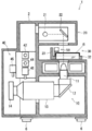
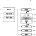
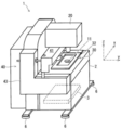
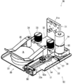
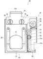
- FIG. 1 is a vertical cross-sectional side view of an imaging apparatus according to a first embodiment of the present invention. It is a block diagram which shows the structure of the imaging device of FIG. It is a perspective view of the imaging device of FIG. FIG. 4 is a perspective view of the same imaging apparatus as in FIG. 3 and shows a state where the stage unit has moved forward. It is a perspective view of the stage part of the imaging device of FIG. It is a top view of the stage part of FIG. 2 is a flowchart illustrating an operation related to determination of a floating state and an attached state of cells by the imaging apparatus of FIG. 1. It is explanatory drawing which shows the example of the image of the different time imaged with the imaging device of FIG.
- FIG. 1 It is a flowchart which shows the operation
- FIG. 2nd embodiment of the present invention It is a block diagram which shows the structure of the imaging device of FIG. It is a front view of the vibration part of the imaging device of FIG. It is a side view of the vibration part of FIG.
- the imaging unit 10 is provided in the lower part of the main body 2 and includes an objective lens 11, a reflection mirror 12, a zoom lens 13, and a CCD camera 14.
- the objective lens 11 is disposed immediately below the stage unit 30 that holds the culture vessel S, and is provided so as to be able to image upward.
- the reflection mirror 12 is disposed below the objective lens 11 and is inclined so as to reflect light substantially horizontally toward the rear. The reflection mirror 12 guides the image obtained from the objective lens 11 to the rear zoom lens 13.
- the zoom lens 13 is disposed behind the reflecting mirror 12 and extends in the front-rear direction.
- the zoom lens 13 enlarges the image obtained from the objective lens 11.
- the CCD camera 14 is disposed further rearward of the zoom lens 13, and an image obtained through the objective lens 11, the reflection mirror 12, and the zoom lens 13 is formed on the imaging element surface. With such a configuration, the imaging unit 10 captures the cells in the culture vessel S as an image.
- the illumination unit 20 is provided on the top of the main body 2 and includes an LED 21 and a reflection mirror 22.
- the LED 21 emits light that illuminates the culture vessel S that is the imaging target of the stage unit 30 located below the illumination unit 20.
- the reflection mirror 22 is arranged vertically above the objective lens 11 and reflects the light irradiated by the LED 21 so as to reach the culture vessel S and the objective lens 11.
- the stage unit 30 is a front central portion of the main body 2 and is provided between the lower imaging unit 10 and the upper illumination unit 20.
- the stage unit 30 holds a culture vessel S containing cells to be imaged and a cell culture solution. The detailed configuration of the stage unit 30 will be described later.
- the drive unit 40 is provided at the rear and side of the stage unit 30 and includes an x-axis drive mechanism 41, an x-axis motor 42, a y-axis drive mechanism 43, a y-axis motor 44, a z-axis motor 45, and a zoom motor 46. Yes. As shown in FIG. 3, the imaging apparatus 1 will be described with the left-right direction as the x-axis, the front-rear direction as the y-axis, and the up-down direction as the z-axis.
- the x-axis drive mechanism 41 is disposed immediately behind the stage unit 30 and directly supports the stage unit 30.
- the x-axis drive mechanism 41 includes a belt, a pulley, a slide guide member, a shaft, and the like (not shown) and is driven by the x-axis motor 42 to move the stage unit 30 in the left-right direction.
- the y-axis drive mechanism 43 is disposed on the side surface of the stage unit 30 and the main body 2 and supports the x-axis drive mechanism 41.
- the y-axis drive mechanism 43 includes a belt, a pulley, a slide guide member, and the like (not shown) and is driven by a y-axis motor 44 to move the stage unit 30 in the front-rear direction together with the x-axis drive mechanism 41 (see FIG. 4).
- the z-axis motor 45 and the zoom motor 46 are disposed in the main body 2 behind the stage unit 30.
- the z-axis motor 45 is a motor for moving the imaging unit 10 in the vertical direction.
- the zoom motor 46 is a motor for changing the magnification of the zoom lens 13 and can change the magnification of an image to be captured.
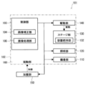
- the image pickup apparatus 1 includes a control unit 3 therein as shown in FIG. 2 in order to control the operation of the entire apparatus.
- the control unit 3 includes a general microcomputer and other electronic components, and controls a series of operations related to the imaging apparatus 1 based on programs and data stored and input in the microcomputer.
- the control unit 3 includes an image correction unit 4 and an image processing unit 5 that perform correction and processing of an image captured by the imaging unit 10. Details of image correction and processing by the image correction unit 4 and the image processing unit 5 will be described later.
- FIG. 5 is a perspective view of the stage unit 30, and FIG. 6 is a top view of the stage unit 30.
- the stage unit 30 includes a holder 31, a container gripping part 32, a mounting screw 33, a rubber 34, a container presser 35, and a vibration unit 50.
- the holder 31 is supported by an x-axis drive mechanism 41 (see FIG. 3) at a portion of the support portion 31a extending substantially vertically, and the lower portion of the support portion 31a has an L shape when viewed from the side extending horizontally toward the front. Yes.
- the container gripping portion 32 is attached to the front of the holder 31 with an attachment screw 33.
- a rubber 34 which is an elastic body is provided between the holder 31 and the tightening portion of the mounting screw 33. That is, the container gripping part 32 is supported by the holder 31 via the rubber 34.
- the container gripping portion 32 is horizontal, and a culture container S or the like containing cells and a cell culture solution can be placed on the upper surface thereof.
- the culture vessel S is pressed so as not to move easily by a vessel presser 35 having a leaf spring shape.
- the vibration unit 50 is located on the side of the container gripping part 32 and is attached to the holder 31.
- the vibration unit 50 includes a base 51, a lever 52, a support shaft 53, a contact piece 54, a motor 55, an eccentric cam 56, a lever tension spring 57, and a grip section tension spring 58.
- the motor 55 and the eccentric cam 56 are provided in the vicinity of the end of the lever 52 opposite to the side where the contact piece 54 is provided, that is, in the vicinity of the end of the lever 52 on the holder 31 side.
- the motor 55 has a vertical rotation axis, and an eccentric cam 56 is rotatably attached to the lowermost part thereof.
- the eccentric cam 56 has a horizontal rotation surface, and a side surface which is a circumferential surface having the cam shape contacts the lever 52. Accordingly, when the motor 55 is driven to rotate the eccentric cam 56, the lever 52 swings around the support shaft 53 so as to displace the contact piece 54 left and right.
- a lever tension spring 57 is provided between the lever 51 and the base 51 at a position closer to the eccentric cam 56 than the support shaft 53 of the lever 52. Since the elastic force of the lever tension spring 57 acts so as to press the lever 52 against the eccentric cam 56, the lever 52 always swings in conjunction with the cam shape of the eccentric cam 56.
- the container gripping portion 32 becomes the swinging portion 60 that swings left and right by the vibrating portion 50, and the vibrating portion 50 operates to give vibration to the swinging portion 60. That is, the vibration part 50 vibrates the rocking
- FIG. Thereby, since only the swinging part 60 provided with the container gripping part 32 is vibrated, the culture solution in the culture vessel S can be shaken by using the vibration part 50 having a relatively small driving force.
- gripping part tension spring 58 is provided between the container gripping part 32 and the base 51, and an elastic force acts so as to press the container gripping part 32 against the contact piece 54.
- the grip portion 32 always swings in conjunction with the cam shape of the eccentric cam 56.
- the vibration unit 50 can adjust the amplitude of the container gripping part 32, which is one of the vibration operation parameters.
- Another example of the vibration operation parameter is the rotation frequency of the motor 55.
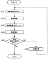
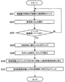
- FIG. 7 is a flowchart showing an operation related to determination of the floating state and the attached state of cells by the imaging apparatus 1.
- the operation flow shown in FIG. 7 includes a step of “cultivation work” assuming that the imaging apparatus 1 of the present invention is incorporated in, for example, a culture apparatus.
- “Cultivation work” may include manual work by a person.
- control unit 3 controls the imaging unit 10 and the illumination unit 20, and first the culture vessel An image of the cells in S is taken (step # 101).
- control unit 3 controls the vibration unit 50 to vibrate the container gripping part 32, which is the rocking unit 60, and rocks the cells in the culture vessel S (step # 102). And the control part 3 images the image of the cell in the culture container S in vibration (step # 103).
- control unit 3 causes the image correction unit 4 to perform image correction (step # 104). That is, the image correcting unit 4 corrects the positional deviation between the images using images at different points of time between the stationary cell image captured in step # 101 and the vibrating cell image captured in step # 103. . As a result, an image obtained by imaging a stationary cell is corrected, so that it is possible to prevent the attached cell from being erroneously determined as being in a floating state.
- control part 3 makes the image processing part 5 discriminate
- the imaging device 1 of the present invention when the imaging device 1 of the present invention is incorporated into a culture device, for example, the number of floating cells with respect to a preset standard value is evaluated as a result of the determination of the floating state and the attached state of the cells as described above.
- the evaluation result No in Step # 105
- necessary culture work is added or parameters in the culture work are adjusted. (Step # 106).
- Step # 106 After the culturing operation in Step # 106, the process returns to Step # 101 again, and evaluation is performed through the processing in Steps # 101 to # 105 to determine whether the cell floating state and the attached state are discriminated.
- Step # 105 When the determination of the floating state and the attached state of the cell is completed in Step # 105 (Yes in Step # 105), the operation related to the determination of the floating state and the attached state of the cell is ended (End in FIG. 7).
- FIG. 8 is an explanatory diagram showing an example of images taken at different times taken by the imaging apparatus 1
- FIG. 9 is an explanatory diagram showing a first example of the image correction method of FIG. 8
- FIG. 10 is a similarity determination of the images of FIG.
- FIG. 11 is an explanatory diagram showing a method (block matching)
- FIG. 11 is an explanatory diagram showing differences between images taken at different points in time
- FIG. 12 is a second example of the image correction method (optical flow) shown in FIG. It is explanatory drawing.
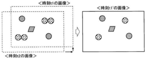
- FIG. 8 shows an image at time t1 when the culture vessel S is stationary and an image at time t2 when the culture vessel S is stationary, as examples of images taken at different times taken by the imaging device 1. Circles and squares in the two images indicate cells. In addition, since these are drawn on the assumption that a positional deviation has occurred between the two images, all cells appear to move in the image regardless of the floating state or the attached state. If there is no displacement between the images, the cells in the attached state will not move between the images.
- the “positional deviation” includes a positional deviation of the imaging target object (observed as a positional deviation of attached cells) due to a difference in imaging location due to vibration of the excitation unit 50, and a positional deviation due to the vibration result of floating cells. There are two types.
- the image correction unit 4 converts the image at the time t1 with the image at the time t2 as a reference, and generates an image at the time t1 'in which the positional deviation is corrected.
- the image correction unit 4 determines the difference between the position of the feature point (cell) in the image at time t1 and the position of the feature point (cell) in the image at time t2 corresponding to this feature point (cell).
- the positional deviation is identified, and an image in which the positional deviation is corrected is generated.
- the image correction unit 4 performs image conversion of translation and rotation based on the position of each feature point (cell) corresponding to the two images.
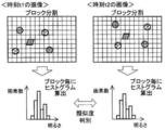
- the image correction unit 4 calculates a histogram by paying attention to a block having an image at time t1.
- the horizontal axis class is the pixel brightness
- the vertical axis frequency is the pixel number.
- the image correction unit 4 calculates a histogram of the same position of the image at the time t2 and its surrounding blocks, and determines the similarity with the histogram of the image at the time t1.
- the image correction unit 4 compares the two histograms and determines their similarity.
- the image correction unit 4 repeats the comparison of the histograms of all the blocks in the images at the times t1 and t2 while shifting the blocks little by little. At this time, the image correction unit 4 repeats the comparison of the histograms while moving the blocks and the images in parallel or rotating. Further, the size of the block may be initially set relatively roughly, and the comparison of histograms may be repeated while reducing the size step by step to increase the accuracy of similarity determination. Then, the position of the image at the time t1 at which the correlation is determined to be highest with the image at the time t2 is calculated, and information on each movement amount of the parallel movement and the rotational movement is obtained as the position information.
- the image correction unit 4 converts the image at the time t1 based on the information on the parallel movement amount and the rotational movement amount to correct the positional shift, and generates the image at the time t1 'on the right side of FIG. It can be seen that in the image at time t1 ', the cells have moved as a whole with respect to the image at time t1, but the relative position between the cells has not changed.
- an optical flow technique is used as a specific example of an image correction method for converting an image at time t1 on the basis of an image at time t2 to generate an image at time t1 ′ in which the positional deviation is corrected.
- the image correction unit 4 first calculates the feature point flow using the images at time t1 and time t2.
- the flow by the optical flow may be referred to as “flow”.
- the image correction unit 4 calculates the flow that occupies the majority of all the cells, and regards this as the flow of the adherent cells. Since the adherent cells do not move between the images at time t1 and time t2, the flow of the adherent cells is determined as a vibration component (positional deviation). As a result, the image correction unit 4 moves and corrects the image at time t1 by the amount of vibration, and generates an image at time t1 'at the lower end of FIG. As in FIG. 9 in the case of block matching, in the image at time t1 ', the cells move as a whole with respect to the image at time t1, but the relative position between the cells does not change. Furthermore, if the difference between the image at time t1 'and the image at time t2 is taken, cells in a floating state can be determined as shown in FIG.
- the flow that deviates significantly may be excluded by M estimation, for example, and the average flow may be calculated to generate a corrected image once. Then, the flow is calculated using the corrected image and the image at time t2. Furthermore, the accuracy of correction may be increased by repeating the generation of the corrected image and the flow calculation using the corrected image and the image at time t2.
- the floating image may be determined by correcting (converting) the image at time t2 on the basis of the image at time t1 and using the newly created image at time t2 'and the image at time t1.
- the processing of the image correction unit 4 makes the attachment position of the cell in the attached state clear, so that the movement state of the cell in the floating state can be easily grasped. Then, by appropriately changing the image moving method for image conversion, it is possible to efficiently correct misalignment between images.
- FIG. 13 is an explanatory view showing a floating state, an attached state, and a locally attached state of cells.
- the cells may exist at the same position between the two images, and it may not be determined that the cells are in a floating state. Therefore, a method called “integration between multiple images” is applied by integrating the discrimination results using a plurality of images including images taken during vibration.
- FIGS. 14 is a schematic explanatory diagram of the integration between a plurality of images
- FIG. 15 is a detailed explanatory diagram of the integration between a plurality of images
- FIG. 16 is a flowchart showing an operation related to specifying the same moving area between images at different points in the explanatory diagram of FIG.
- FIG. 17 is a flowchart showing operations related to tracking and integration of floating regions in the explanatory diagram of FIG.
- the image processing unit 5 uses the floating image described with reference to FIGS. 7 to 13 from a plurality of images (images 1 to 4 or less) including images taken during vibration as shown in FIG. A region (floating region, a circle in FIG. 14) that is made floating by the result obtained by the method for discriminating cells in a state is extracted. Further, the image processing unit 5 integrates the images extracted from the floating regions. Thereby, it is not necessary to synchronize the timing of imaging and swinging, and the determination result of the floating state and the attached state can be obtained regardless of the adherence of the cells.
- the image processing unit 5 uses two continuous floating region extraction images, for example, an image k and an image k + 1, to generate a moving region (floating region, circle in FIG. 15) based on the difference between the images. Extraction and calculation of optical flow. Then, using these results, the image processing unit 5 identifies the same moving area. Processing related to the identification of the same moving area will be described along the flow shown in FIG.
- the floating region extraction image may be generated as follows. That is, when the floating image is determined by correcting the image at time t2 using the image at time t1 as a reference, the image at time t2 'generated by the image correction unit 4 is set as the floating region extraction image k. Further, when the floating image is discriminated by correcting the image at time t3 on the basis of the image at time t2, the correction amount used when generating the image at time t2 ′ is further added to the generated image at time t3 ′. In consideration, it is set as the floating region extraction image k + 1. Thereafter, similarly, by accumulating the correction amount up to the previous processing, it is possible to obtain a temporally continuous floating region extraction image with reference to the position of the adherent cell at time t1.
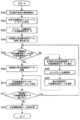
- the image processing unit 5 When the image processing unit 5 starts processing related to identification of the same moving area (start of FIG. 16), it checks the moving area to which the feature point of the current image belongs (step # 201). Next, the image processing unit 5 applies flow by optical flow to the checked moving area (step # 202). Then, the image processing unit 5 determines whether or not the flow has been applied to all moving regions (step # 203). When the flow has not been applied to all moving regions (No in step # 203), the image processing unit 5 repeats the processes in steps # 201 and # 202.
- step # 203 the image processing unit 5 checks the flow applied to each moving region (step # 204), and excludes the conspicuous flows that deviate relatively greatly. Then, the average of the flow is calculated (step # 205).
- step # 301 means the processing described in the flow of FIG.
- “current image” means two continuous floating region extracted images in FIG. 15, for example, an image k + 1 in the case of the image k and the image k + 1.
- the image k means a “previous image” described later.
- the image processing unit 5 converts the estimated floating area of the current image into a template and calculates a histogram (step # 302). Further, in addition to the histogram, the image processing unit 5 acquires template information such as the region position and region size obtained from the estimated floating region of the current image, and sets it as floating cell estimation data (step # 303).
- the floating cell estimation data is composed of an area position, an area size, a histogram, and the like obtained from the estimated floating area.
- the image processing unit 5 acquires the floating cell result data of the previous image (Step # 304).
- the floating cell result data consists of the area position, area size, histogram, etc. obtained from the area counted as floating cells as a result of the series of processing of the previous image, and there are multiple as many as the number of areas counted as floating cells To do.
- the image processing unit 5 superimposes the floating cell result data on the floating cell estimation data.
- the image processing unit 5 determines whether there is floating cell estimation data in the vicinity of the floating cell result data (step # 305).
- the “neighboring” range is, for example, calculated from the maximum flow size observed so far, or the vibration operation parameter set when the vibration unit 60 is vibrated using the vibration unit 50. Or from the amplitude.
- the image processing unit 5 discards the floating cell result data of the previous image (Step # 306). That is, the image processing unit 5 considers that floating cells have moved from the position of the previous image to the position of the current image, and leaves the floating cell estimation data of the current image.
- the image processing unit 5 After step # 307, the image processing unit 5 generates a histogram for the moving area of the floating details of the previous image, and searches for the vicinity using this to track the moving area (step # 308). Note that the “neighboring” range is calculated from, for example, the maximum flow size observed so far, or is the vibration operation parameter set when the vibration unit 60 is vibrated using the vibration unit 50. Or from the amplitude. Then, the image processing unit 5 updates the floating cell estimation data added in step # 307 using the region information detected in step # 308 (step # 309).
- the image processing unit 5 stores the floating cell estimation data of the current image left in step # 306 and the floating cell estimation data updated in step # 309 as floating cell result data of the current image (step #). 310). Then, the image processing unit 5 determines whether or not the floating cell result data of the previous image for which the estimated floating region should be tracked remains (step # 311). When the floating cell result data of the previous image remains (Yes in Step # 311), the process returns to Step # 305, and the image processing unit 5 repeats the processes from Step # 305 to Step # 310.
- the image processing unit 5 counts the floating cells after tracking and integrating the estimated floating region as described above. That is, in the example of FIG. 15, three cells of cell A, cell B, and cell C are counted for the floating region extracted image k and the image k + 1.
- the image processing unit 5 performs the same processing between the floating region extracted image k + 1 and the image k + 2.
- the image forming unit 5 determines that they belong to the same cell movement. That is, in the example of FIG. 15, the cells B and C correspond to this.
- the cell A corresponds to this in the example of FIG.
- the cell D is a cell newly recognized as being in a floating state between the floating region extracted image k + 1 and the image k + 2.
- the vibration operation parameter when vibrating by the current vibration unit 50 may be adjusted.
- the vibration operation parameter can be adjusted during the repetitive processing according to the flow of FIG.
- Examples of the discrimination result of the image processing unit 5 include the number of floating cells and the amplitude of the floating cells, and examples of the excitation operation parameter include the rotation frequency of the motor 55 and the amplitude of the swinging unit 60.
- the vibration state of floating cells and cells locally attached to the culture vessel S is unknown, it is considered that the vibration state fluctuates under the influence of adjusting the vibration operation parameter.
- the vibration operation parameter for the current vibration is adjusted so as to obtain such a vibration condition.
- the state where the cells are locally attached to the culture container and the culture container It is distinguished from the state of being completely attached.
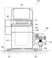
- the imaging apparatus 101 has a main body 102 supported by legs 106 including leg rubbers 107 that are elastic bodies provided at four locations on the floor surface. Yes. Furthermore, the main body 102 includes a vibration unit 150 bonded to the side surface thereof. As shown in FIGS. 18 and 19, the excitation unit 150 causes the main body 102 supported by the leg rubber 107 to vibrate as the oscillation unit 160.
- the base 151 is composed of an L-shaped plate-like member as viewed from the front, which includes a vertical portion 151a and a horizontal portion 151b extending in the front-rear direction.
- the vibrating portion 150 is joined to the main body 102 at the vertical portion 151 a of the base 151.
- the base 151 includes a vertical wall extending in the left-right direction, and includes a reinforcing portion 151c that is connected to the vertical portion 151a and the horizontal portion 151b to reinforce the configuration.
- the lever 152 extends in the left-right direction and is supported by the reinforcing portion 151c of the base 151 with a support shaft 153.
- the support shaft 153 is provided at the outermost end of the lever 152.
- the lever 152 is supported so as to be rotatable in a vertical plane around the support shaft 153.
- the contact piece 154 is provided on the inner side of the support shaft 153 of the lever 152, that is, at a position on the main body 102 side.
- the contact piece 154 is attached to a long hole 152a provided in the lever 152 so as to extend in the left-right direction, and the attachment location can be changed in the left-right direction along the long hole 152a.
- the contact piece 154 has a roller shape, and a side surface which is a peripheral surface thereof contacts an upper end portion 158 a of the pusher 158 positioned below the contact piece 154.
- a slide guide 157 is provided in the vertical portion 151 a at the end of the lever 152 on the main body 102 side.
- the end portion of the lever 152 on the main body 102 side is housed in a guide groove 157 a extending in the vertical direction of the slide guide 157. Accordingly, the slide guide 157 guides the lever 152 so as to be movable only in the vertical direction, and restricts the movement in the front-rear direction.
- a pusher spring 159 is provided between the upper end portion 158a of the pusher 158 and the upper surface of the horizontal portion 151b. Since the elastic force of the pusher spring 159 acts so as to press the upper end 158 a of the pusher 158 against the contact piece 154 and the lever 152 against the eccentric cam 156, the pusher 158 and the lever 152 always have the cam shape of the eccentric cam 156. Swing in conjunction.
- the vibration unit 150 is joined to the main body 102 which is the rocking unit 160 and operates so as to apply vibration to the main body 102.
- the vibration unit 150 vibrates with an amplitude smaller than the displacement of the leg rubber 107 provided on the leg 106 of the imaging device 101.
- the vibration unit 150 vibrates together with the rocking unit 160, so that the imaging apparatus 101 in which the entire apparatus vibrates can be configured.
- the container gripping unit 132 and the imaging unit 110 are provided together in the swinging unit 160. Therefore, the container gripping unit 132 and the imaging unit 110 are provided. At the same time, the same vibration can be given. Therefore, the relative displacement between the culture vessel S and the imaging unit 110 can be suppressed, and the effect of preventing the displacement between images at different time points can be further enhanced.
- the vibration unit 150 can adjust the amplitude of the main body 102, which is one of the vibration operation parameters.
- the determination results are integrated using three floating region extracted images, image k, image k + 1, and image k + 2, in FIG. 15, but the number of images is limited to three. However, it may be two or four or more.
- the rubber 34 that is an elastic body that supports the rocking portion 60 in the first embodiment and the leg rubber 107 that is an elastic body that supports the rocking portion 160 in the second embodiment may be omitted.
- the elastic body is not limited to rubber, and may be a spring or a sponge.
Landscapes
- Engineering & Computer Science (AREA)
- Life Sciences & Earth Sciences (AREA)
- Chemical & Material Sciences (AREA)
- Zoology (AREA)
- Health & Medical Sciences (AREA)
- Bioinformatics & Cheminformatics (AREA)
- Organic Chemistry (AREA)
- Wood Science & Technology (AREA)
- Theoretical Computer Science (AREA)
- General Physics & Mathematics (AREA)
- Physics & Mathematics (AREA)
- Multimedia (AREA)
- General Engineering & Computer Science (AREA)
- Analytical Chemistry (AREA)
- Cell Biology (AREA)
- General Health & Medical Sciences (AREA)
- Genetics & Genomics (AREA)
- Sustainable Development (AREA)
- Microbiology (AREA)
- Biochemistry (AREA)
- Biotechnology (AREA)
- Biomedical Technology (AREA)
- Computer Vision & Pattern Recognition (AREA)
- Signal Processing (AREA)
- Apparatus Associated With Microorganisms And Enzymes (AREA)
- Image Processing (AREA)
- Image Analysis (AREA)
Abstract
【課題】複数の異なる時点の画像を用いて培養容器内における培養液中の細胞の浮遊状態、付着状態を精度よく判別することが可能な撮像装置を提供する。 【解決手段】撮像装置1は、細胞と培養液とが入った培養容器Sを把持する容器把持部32と、容器把持部32が設けられた揺動部60と、揺動部60に振動を与える加振部50と、培養容器S内の細胞を画像として撮像する撮像部10と、撮像部10が撮像した少なくとも一の振動中の画像を含む複数の撮像場所の画像を用いて、撮像場所が異なることにより生じる画像間の位置ずれを補正する画像補正部4と、撮像部10が撮像した画像と画像補正部4が補正した画像とを用いて細胞の浮遊状態または付着状態を判別する画像処理部5と、を備える。その結果、付着状態の細胞を浮遊状態であると誤って判別することが防止され、細胞の局部的に付着している状態と完全に付着している状態とが区別される。
Description
本発明は、細胞などの撮像装置に関する。
細胞の培養は培養液を注いだディシュやシャーレなどの培養容器を用いて行われる。そして、培養時間が経過すると、培養容器内が細胞で埋め尽くされたり、細胞の増殖が進行し難い状況になったりすることがある。このため、培養細胞を回収し、新たな容器に移して培養を維持する継代培養が行われることがある。
継代培養では培養容器に付着した細胞を剥離する必要があるが、細胞の個体差により付着状況が異なることが多い。したがって、細胞の培養容器への付着状況に合わせて剥離前の細胞の洗浄回数や洗浄流量を調整したり、トリプシン剥離における剥離までの時間を調整したり、剥離作業を完遂するために培養容器を叩く力や叩く回数を変更したりしなければならない。このため、培養容器内における培養液中の細胞の浮遊状態、付着状態を正確に判断する必要がある。さらに、培養容器内の細胞の浮遊状態、付着状態を判別できれば、培養容器への細胞播種後生着率を概算することも可能である。
このような培養容器内における培養液中の細胞の浮遊状態、付着状態を判別する手法の例を特許文献1及び2に見ることができる。特許文献1に記載された識別装置は培養容器を載置したステージを移動させて培養容器内に対流を発生させ、培養容器内で浮遊している細胞の位置がずれ、且つ接着している細胞の位置がずれない程度の物理的振動を与えるようにして画像を撮像、解析している。特許文献2に記載された細胞剥離判断方法は加振台に載置された培養容器を加振台ごと振動させる構成で、培養液の静止中及び加振後の2枚の画像を撮像して培養液中の細胞の浮遊状態、付着状態を判別している。
しかしながら、特許文献1に記載された識別装置は培養容器内で対流を発生させるために培養容器を載置したステージを移動させているので、ステージを移動させるための機械要素間にバックラッシュ等が発生する可能性がある。これにより、ステージの移動の前後で同一位置において画像を撮像しても位置がずれる虞があり、付着状態の細胞を浮遊状態であると誤って判別することが懸念される。さらに、この識別装置は接着(付着)している細胞の位置がずれない程度の物理的振動を与えることを前提としており、ステージの移動の前後で撮像した2枚の画像に位置ずれが発生する可能性があることについて考慮されていない。
また、特許文献2に記載された細胞剥離判断方法は加振台に載置された培養容器を加振台ごと振動させているが、培養容器自体の製造時に生じる寸法誤差や加振台の培養容器取り付け箇所に生じるクリアランスなどに起因して培養容器が意図せず移動する虞がある。これにより、撮像した2枚の画像に位置ずれが発生する可能性があり、付着状態の細胞を浮遊状態であると誤って判別することが懸念される。そして、この細胞剥離判断方法では2枚の画像の位置ずれについて考慮されていないので、培養液中の細胞の浮遊状態、付着状態を適切に判別できない可能性が高い。
一方、培養液中の細胞の浮遊状態、付着状態に関して、細胞に粘性があり、細胞の一部が培養容器に付着し、別の一部が培養液中を浮遊しているような状態も存在する。このような局部的に付着している状態は、特許文献1及び2では細胞が培養容器に完全に付着している状態と区別することができない可能性が高い。したがって、特許文献1及び2では細胞が培養容器に局部的に付着している状態が培養容器に完全に付着している状態として誤って判別される虞がある。
本発明は上記の点に鑑みなされたものであり、複数の異なる時点の画像を用いて培養容器内における培養液中の細胞の浮遊状態、付着状態を精度よく判別することが可能な撮像装置を提供することを目的とする。また、培養容器に局部的に付着している細胞を浮遊細胞として明確に判別することが可能な撮像装置を提供することを目的とする。
上記の課題を解決するため、本発明の撮像装置は、細胞と培養液とが入った容器を把持する容器把持部と、前記容器把持部が設けられた揺動部と、前記揺動部に振動を与える加振部と、前記容器内の細胞を画像として撮像する撮像部と、前記撮像部が撮像した少なくとも一の振動中の画像を含む複数の撮像場所の画像を用いて、撮像場所が異なることにより生じる画像間の位置ずれを補正する画像補正部と、前記撮像部が撮像した画像と前記画像補正部が補正した画像とを用いて細胞の浮遊状態または付着状態を判別する画像処理部と、を備える。
なお、加振部が振動させているので、異なる時点において撮像部が撮像する撮像場所は振動の周期と同期しない限り一般に異なることとなる。画像補正部はそれら異なる時点の画像における各々の撮像場所が一般に異なることから、その異なることに依存した細胞等の撮像対象物などの位置ずれを補正するものである。
この構成によれば、振動中の画像を含む複数の異なる時点の画像を用いて画像間の位置ずれを補正するので、付着状態の細胞を浮遊状態であると誤って判別することが防止される。さらに、細胞が培養容器に局部的に付着している状態と培養容器に完全に付着している状態とが区別される。
また、上記構成の撮像装置において、前記画像補正部は、一の画像における第1の特徴点の位置と、他の画像における前記第1の特徴点に対応する第2の特徴点の位置との差から画像間の位置ずれを識別し、その位置ずれを補正した画像を生成しても良い。なお、以下「特徴点」とは、例えばエッジ検出などの結果として安定的に検出可能な画像上の特徴的な点であり、例えば画像上の細胞を意味する。また、画像を複数のブロックに分割した場合の特徴的なブロックを特徴点としても良い。
この構成によれば、付着状態にある細胞のその付着位置が明確になるので、浮遊状態にある細胞の移動状況が把握し易くなる。
また、上記構成の撮像装置において、前記画像補正部は、二の画像間で対応する二の特徴点の位置に基づき平行移動、回転移動の画像変換を行っても良い。
この構成によれば、画像変換のための画像の移動方法を適宜変更することにより、画像間の位置ずれ補正を効率よく行うことができる。
また、上記構成の撮像装置において、前記画像処理部は、三以上の異なる時点の画像を用い、各画像間の差分により導出した画像における細胞の浮遊領域候補を各差分間で追跡、積算することにより細胞の浮遊状態を判別しても良い。
この構成によれば、連続する各画像間で細胞の浮遊状態が把握できるので、複数の異なる時点の画像間において細胞が常に移動していない場合でも細胞の浮遊状態が識別される。
また、上記構成の撮像装置において、前記揺動部は、弾性体によって支持されていても良い。なお、揺動部と弾性体との間に他の部材が介在してもよい。
この構成によれば、弾性体の弾性変形を利用できるので、培養容器内の浮遊状態にある細胞の移動量が比較的大きくなるのを期待でき、細胞の浮遊状態、付着状態を判別し易くなる。
また、上記構成の撮像装置において、前記加振部は、前記揺動部に接合され、前記弾性体の変位より小さい振幅で振動させても良い。
この構成によれば、加振部が揺動部と一緒に振動するので、例えば装置全体が振動する撮像装置を構成することができる。これにより、培養容器と撮像部との間の相対的な変位を抑制でき、異なる時点の画像間の位置ずれを防止する作用がより高められる。
また、上記構成の撮像装置において、ホルダにて支持された前記容器把持部を水平方向に移動させるステージ部を備え、前記加振部は、前記揺動部と前記ホルダとの間に存在する支点によって前記揺動部を振動させても良い。なお、「揺動部とホルダとの間」には「揺動部自体」及び「ホルダ自体」も含むものとする。すなわち、支点は揺動部自体またはホルダ自体または揺動部とホルダとの間に存在する。
この構成によれば、容器把持部が設けられた揺動部のみを振動させるので、比較的小さな駆動力の加振部を用いて培養容器内の培養液を揺らすことができる。
また、上記構成の撮像装置において、前記撮像部は、前記揺動部に設けられることにしても良い。
この構成によれば、容器把持部と撮像部とが一緒に揺動部に設けられていることになるので、容器把持部と撮像部とに対して同時に、同じ振動を与えることができる。これにより、培養容器と撮像部との間の相対的な変位を抑制でき、異なる時点の画像間の位置ずれを防止する作用がより高められる。
また、上記構成の撮像装置において、前記加振部が加振動作パラメータを調整可能に構成され、前記加振動作パラメータを用いて得られた前記画像処理部の前回の判別結果に基づき今回の前記加振動作パラメータを調整しても良い。
培養容器に局部的に付着している細胞の振動具合は加振部の加振動作パラメータの影響を受けると考えられるので、この構成によれば、培養容器に局部的に付着している細胞を浮遊細胞として明確に判別するのに好適な振動状況が得られる。
本発明の構成によれば、複数の異なる時点の画像を用いて培養容器内における培養液中の細胞の浮遊状態、付着状態を精度よく判別することが可能な撮像装置を提供することができる。また、培養容器に局部的に付着している細胞を浮遊細胞として明確に判別することが可能な撮像装置を提供することができる。
以下、本発明の実施形態を図1~図21に基づき説明する。
(第1の実施形態) 最初に、本発明の第1の実施形態に係る撮像装置について、図1~図4を用いてその構造を説明する。図1は撮像装置の垂直断面側面図、図2は撮像装置の構成を示すブロック図、図3は撮像装置の斜視図、図4は撮像装置の斜視図にして、ステージ部が前方に移動した状態を示すものである。なお、図3では培養容器の描画を省略している。また、以下の説明において、図3のx軸方向を左右方向、y軸方向を前後方向(+y方向を前方、-y方向を後方)、z軸方向を上下方向とする。
撮像装置1は、図1~図3に示すようにその筐体である本体2に撮像部10、照明部20、ステージ部30、及び駆動部40を備えている。撮像装置1はその正面中央部に配置された培養容器S内の細胞の撮像部10及び照明部20を用いた撮像が可能で、駆動部40によって培養容器Sを把持するステージ部30を前後、左右の所望の方向、位置に移動させることができる。なお、本体2は床面に対して四箇所に設けられた脚部6によって支持されている。
撮像部10は本体2の下部に設けられ、対物レンズ11、反射ミラー12、ズームレンズ13、及びCCDカメラ14を備えている。対物レンズ11は培養容器Sを把持するステージ部30のすぐ下方に配置され、上方に向かって撮像可能にして設けられている。反射ミラー12は対物レンズ11の下方に配置され、後方に向かって略水平に光を反射するよう傾斜させて設けられている。反射ミラー12は対物レンズ11から得られた像を後方のズームレンズ13に導く。
ズームレンズ13は反射ミラー12の後方に配置され、前後方向に延びる形で設けられている。ズームレンズ13は対物レンズ11から得られた像を拡大する。CCDカメラ14はズームレンズ13のさらに後方に配置され、対物レンズ11、反射ミラー12、及びズームレンズ13を経て得られる像がその撮像素子面で結像する。このような構成により、撮像部10は培養容器S内の細胞を画像として撮像する。
照明部20は本体2の上部に設けられ、LED21、及び反射ミラー22を備えている。LED21は照明部20の下方に位置するステージ部30の撮像対象である培養容器Sを照らす光を発する。反射ミラー22は対物レンズ11の鉛直上方に配置され、LED21が照射した光が培養容器S及び対物レンズ11に到達するよう反射させる。
ステージ部30は本体2の正面中央部であって、下方の撮像部10と上方の照明部20とに挟まれた形で設けられている。ステージ部30は撮像対象である細胞と細胞の培養液とが入った培養容器Sを把持している。ステージ部30の詳細な構成は後述する。
駆動部40はステージ部30の後方及び側方に設けられ、x軸駆動機構41、x軸モータ42、y軸駆動機構43、y軸モータ44、z軸モータ45、及びズームモータ46を備えている。なお、図3に示すように撮像装置1に対して左右方向をx軸と、前後方向をy軸と、上下方向をz軸として説明する。
x軸駆動機構41はステージ部30のすぐ後方に配置されるとともにステージ部30を直接支持している。x軸駆動機構41は図示しないベルト、プーリ、スライドガイド部材、シャフト等を備えてx軸モータ42によって駆動され、ステージ部30を左右方向に移動させる。y軸駆動機構43はステージ部30及び本体2の側面の箇所に配置され、x軸駆動機構41を支持している。y軸駆動機構43は図示しないベルト、プーリ、スライドガイド部材等を備えてy軸モータ44によって駆動され、x軸駆動機構41とともにステージ部30を前後方向に移動させる(図4参照)。
z軸モータ45及びズームモータ46はステージ部30後方の本体2内に配置されている。z軸モータ45は撮像部10を上下方向に移動させるためのモータである。ズームモータ46はズームレンズ13の拡大倍率の変更させるためのモータであり、撮像する画像の倍率変更が可能である。
また、撮像装置1は装置全体の動作制御のため、図2に示すようにその内部に制御部3を備えている。制御部3は一般的なマイコンやその他の電子部品によって構成され、このマイコン内部等に記憶、入力されたプログラム、データに基づいて撮像装置1に係る一連の動作を制御する。また、制御部3は撮像部10によって撮像された画像の補正や処理を行う画像補正部4及び画像処理部5を備えている。画像補正部4及び画像処理部5による画像の補正や処理の詳細は後述する。
続いて、ステージ部30の詳細な構成について、図3に加えて、図5及び図6を用いて説明する。図5はステージ部30の斜視図、図6はステージ部30の上面図である。
ステージ部30は図5及び図6に示すようにホルダ31、容器把持部32、取り付けネジ33、ゴム34、容器押さえ35、及び加振部50を備えている。
ホルダ31は略垂直に延びる支持部31aの箇所をx軸駆動機構41(図3参照)によって支持され、支持部31a下部が前方に向かって水平に延びる側方から見てL字形状をなしている。容器把持部32はホルダ31の前方に取り付けネジ33によって取り付けられている。なお、取り付けネジ33の締め付け箇所であってホルダ31との間には弾性体であるゴム34は設けられている。すなわち、容器把持部32はゴム34を介してホルダ31に支持されている。容器把持部32は水平をなし、その上面に細胞と細胞の培養液とが入った培養容器S等を載置することができる。培養容器Sは板ばね形状をなす容器押さえ35によって容易に移動しないよう押さえられている。
加振部50は容器把持部32の側方に位置し、ホルダ31に取り付けられている。加振部50はベース51、レバー52、支軸53、接触片54、モータ55、偏心カム56、レバー引張バネ57、及び把持部引張バネ58を備えている。
ベース51は容器把持部32の側方の近接する箇所において、ホルダ31から前方に向かって延びる形でホルダ31に固定されている。レバー52は前後方向に向かって延び、支軸53でベース51に支持されている。レバー52は支軸53を中心として水平面内で回転可能にして支持されている。
接触片54はレバー52の支軸53より前方の箇所に設けられている。接触片54はレバー52に前後方向に向かって延びる形で設けられた長穴52aに対して取り付けられ、この長穴52aに沿って前後方向に取り付け箇所の変更が可能である。また、接触片54はローラ形状をなし、その周面である側面が容器把持部32の側壁32aに接触する。
モータ55及び偏心カム56はレバー52の支軸53を隔てて接触片54が設けられた側と反対側の端部、すなわちレバー52のホルダ31側の端部近傍に設けられている。モータ55は回転軸線が垂直をなし、その最下部に偏心カム56が回転可能に取り付けられている。偏心カム56はその回転面が水平をなし、そのカム形状を有する周面である側面がレバー52に接触する。これにより、モータ55を駆動させて偏心カム56を回転させると、レバー52が支軸53を中心としてその前方、すなわち接触片54を左右に変位させるように揺動する。
なお、レバー引張バネ57がレバー52の支軸53より偏心カム56側の箇所にベース51との間に設けられている。レバー52を偏心カム56に押し付けるようにレバー引張バネ57の弾性力が作用しているので、レバー52は常に偏心カム56のカム形状に連動して揺動する。
モータ55の駆動によりレバー52が偏心カム56のカム形状に連動して揺動すると接触片54も揺動し、接触片54に接触する容器把持部32が接触片54よって左右方向に押されることとなる。その結果、容器把持部32は取り付けネジ33を用いてゴム34を介してホルダ31に支持されているので、ゴム34が弾性変形し、容器把持部32が左右に揺動する。すなわち、ゴム34の弾性変形を利用できるので、培養容器S内の浮遊状態にある細胞の移動量が比較的大きくなるのを期待でき、細胞の浮遊状態、付着状態を判別し易くなる。
このようにして、容器把持部32は加振部50によって左右に揺動する揺動部60となり、加振部50は揺動部60に振動を与えるように動作する。すなわち、加振部50は揺動部60とホルダ31との間の取り付けネジ33の箇所に存在する支点によって揺動部60を振動させる。これにより、容器把持部32が設けられた揺動部60のみを振動させるので、比較的小さな駆動力の加振部50を用いて培養容器S内の培養液を揺らすことができる。
なお、把持部引張バネ58が容器把持部32とベース51との間で設けられ、容器把持部32を接触片54に押し付けるように弾性力が作用しているので、揺動部60である容器把持部32は常に偏心カム56のカム形状に連動して揺動する。
また、接触片54の取り付け位置を長穴52aに沿って前後方向に変更することにより接触片54と容器把持部32との接触位置が変更できるので、容器把持部32の振幅が変更可能である。このようにして、加振部50は加振動作パラメータのひとつである容器把持部32の振幅の調整が可能である。また、加振動作パラメータの他の例として、モータ55の回転周波数などが挙げられる。
続いて、撮像装置1による培養容器S内の細胞の浮遊状態、付着状態の判別に係る動作について、図2を用いて、図7に示すフローに沿って説明する。図7は撮像装置1による細胞の浮遊状態、付着状態の判別に係る動作を示すフローチャートである。
なお、図7に示す動作フローは本願発明の撮像装置1を例えば培養装置に組み込んだ場合を想定し、「培養作業」のステップを含んでいる。「培養作業」には人による手作業を含む場合がある。
撮像装置1において培養容器S内の細胞の浮遊状態、付着状態の判別に係る動作をスタート(図7のスタート)させると、制御部3は撮像部10及び照明部20を制御し、まず培養容器S内の細胞の画像を撮像する(ステップ#101)。
次に、制御部3は加振部50を制御して揺動部60である容器把持部32に振動を与え、培養容器S内の細胞を揺動させる(ステップ#102)。そして、制御部3は振動中の培養容器S内の細胞の画像を撮像する(ステップ#103)。
ここで、制御部3は画像補正部4に画像補正を実行させる(ステップ#104)。すなわち、画像補正部4はステップ#101で撮像した静止中の細胞の画像とステップ#103で撮像した振動中の細胞の画像との異なる時点の画像を用いて、画像間の位置ずれを補正する。これにより、静止中の細胞を撮像した画像が補正されるので、付着状態の細胞を浮遊状態であると誤って判別することが防止される。
そして、制御部3は画像処理部5に細胞の浮遊状態、付着状態を判別させる(ステップ#105)。すなわち、画像処理部5はステップ#103で撮像部10が撮像した振動中の細胞の画像とステップ#104で画像補正部4が補正した静止中の細胞の画像とを用いて細胞の浮遊状態、付着状態の判別する。
ここで、本発明の撮像装置1を例えば培養装置に組み込んだ場合、上記のような細胞の浮遊状態、付着状態の判別の結果として、予め設定した標準値に対する浮遊細胞数の多寡を評価する。その評価結果に応じて、細胞の浮遊状態、付着状態の判別が完了していないと判断された場合(ステップ#105のNo)、例えば必要な培養作業を加えたり、培養作業におけるパラメータを調整したりする(ステップ#106)。
ステップ#106の具体的な培養作業としては、例えば死細胞除去のための洗浄操作や培地交換、付着作業を剥離して回収する継代操作などがある。培養作業におけるパラメータ調整については、例えば洗浄操作の洗浄時間や洗浄回数を増加したり、剥離剤添加後の反応時間や反応後の培養容器タッピング回数を増加したりするなどの調整を行う。
そして、ステップ#106の培養作業後、再度ステップ#101に戻ってステップ#101~#105の処理を経て評価を行い、細胞の浮遊状態、付着状態の判別の良否を判断する。
ステップ#105において細胞の浮遊状態、付着状態の判別が完了した場合(ステップ#105のYes)、細胞の浮遊状態、付着状態の判別に係る動作を終了する(図7のエンド)。
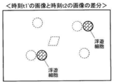
続いて、細胞の浮遊状態、付着状態の判別に係る動作に関して、図7のステップ#104で画像補正部4が実行する画像補正について、図8~図12を用いて説明する。図8は撮像装置1で撮像した異なる時点の画像の例を示す説明図、図9は図8の画像の補正方法の第一例を示す説明図、図10は図8の画像の類似度判別方法(ブロックマッチング)を示す説明図、図11は撮像装置1で撮像した異なる時点の画像の差分を示す説明図、図12は図8の画像の補正方法の第二例(オプティカルフロー)を示す説明図である。
図8は撮像装置1で撮像した異なる時点の画像の例として、培養容器Sが静止中の時刻t1の画像と、振動中の時刻t2の画像とを示している。2つの画像中の丸印及び四角印は細胞を示している。なお、これらは2つの画像間において位置ずれが生じたことを想定して描画しているので、浮遊状態、付着状態にかかわらずすべての細胞が画像中で移動しているように見える。画像間に位置ずれが生じなかった場合、付着状態にある細胞は画像間で移動しないことになる。
一方で、加振部50が振動させているので、異なる時点において撮像部10が撮像する場所は振動の周期と同期しない限り一般に異なることとなる。さらに、たとえ振動と同期させて撮像したとしても、構造上のクリアランスやバックラッシ等により、完全に撮像場所を一致させることは困難である。このため、図8に示す時刻t1の画像と時刻t2の画像とは浮遊状態、付着状態にかかわらずすべての細胞が画像中で移動しているように見える。画像補正部4はそれら異なる時点の画像における各々の撮像場所が一般に異なることから、その異なることに依存した細胞等の撮像対象物などの位置ずれを補正するものである。
よって、「位置ずれ」には、加振部50の振動によって撮像場所が異なることによる撮像対象物の位置ずれ(付着細胞の位置ずれとして観測される)と、浮遊細胞の振動結果による位置ずれと、の2種類がある。
そして、画像補正部4は、図9に示すように時刻t2の画像を基準として時刻t1の画像を変換し、位置ずれを補正した時刻t1’の画像を生成する。これに関して、画像補正部4は時刻t1の画像における特徴点(細胞)の位置と、この特徴点(細胞)に対応する時刻t2の画像における特徴点(細胞)の位置との差から画像間の位置ずれを識別し、その位置ずれを補正した画像を生成する。また、画像補正部4は2つの画像間で対応する各々の特徴点(細胞)の位置に基づき平行移動、回転移動の画像変換を行う。
このような画像補正方法の具体的な例として、ブロックマッチングの手法を第一例に掲げ、図10を用いて説明する。時刻t2の画像を基準として時刻t1の画像を変換して位置ずれを補正した時刻t1’の画像を生成する際、画像補正部4はまず時刻t1及び時刻t2の画像を各々ブロック分割する。各ブロックは、例えば縦100ピクセル×横100ピクセルといった複数の画素を含んでいる。
そして、画像補正部4は時刻t1の画像のあるブロックについて着目してヒストグラムを算出する。ヒストグラムは、例えば横軸の階級を画素の明るさとし、縦軸の度数を画素数としている。続いて、画像補正部4は時刻t2の画像の同じ位置及びその周辺のブロックのヒストグラムを算出し、時刻t1の画像のヒストグラムとの類似度を判別する。画像補正部4は2つのヒストグラムを比較してそれらの類似度を判断する。
引き続き、画像補正部4は少しずつブロックをずらしながら、時刻t1及びt2の画像中のすべてのブロックの各々のヒストグラムの比較を繰り返す。このとき、画像補正部4はブロックや画像を平行移動、或いは回転移動させながらヒストグラムの比較を繰り返す。また、ブロックの大きさは当初比較的大まかに設定し、段階的に小さくしながらヒストグラムの比較を繰り返すことにより類似度の判別の精度を高めても良い。そして、時刻t2の画像を基準として最も相関が高いと判断される時刻t1の画像の位置を算出し、その位置情報として平行移動及び回転移動の各移動量の情報を得る。
これにより、画像補正部4は平行移動量及び回転移動量の情報に基づいて時刻t1の画像を変換して位置ずれを補正し、図9右側の時刻t1’の画像を生成する。時刻t1’の画像では時刻t1の画像に対して細胞が全体的に移動しているが、細胞間の相対位置は変化していないことがわかる。
そして、時刻t1’の画像と時刻t2の画像との差分をとれば、図11に示すように浮遊状態にある細胞を判別することができる。
また、時刻t2の画像を基準として時刻t1の画像を変換し、位置ずれを補正した時刻t1’の画像を生成する画像補正方法の具体的な例として、オプティカルフロー(optical flow)の手法を第二例に掲げ、図12を用いて説明する。この場合、画像補正部4はまず時刻t1及び時刻t2の各々の画像を用いて特徴点フローを算出する。なお、以下の説明において、フローチャートの「フロー」との混同を避けるため、オプティカルフローによるフローを「flow」と表記することがある。
そして、画像補正部4はすべての細胞に対して大勢を占めるflowを算出し、これを付着細胞のflowとみなす。付着細胞は時刻t1及び時刻t2の画像間で移動しないので、付着細胞のflowが振動分(位置ずれ)と判別される。これにより、画像補正部4は時刻t1の画像を振動分だけ移動して補正し、図12下端の時刻t1’の画像を生成する。ブロックマッチングの場合の図9同様、時刻t1’の画像では時刻t1の画像に対して細胞が全体的に移動しているが、細胞間の相対位置は変化していない。さらに、時刻t1’の画像と時刻t2の画像との差分をとれば、図11に示すように浮遊状態にある細胞を判別することができる。
なお、flowの算出処理において、大きく外れたflowを例えばM推定で除外して平均flowを算出し、これにより一旦補正画像を生成しても良い。そして、この補正画像と時刻t2の画像とを用いてflowを算出する。さらに引き続き補正画像の生成と、補正画像と時刻t2の画像とを用いたflow算出とを繰り返すことにより補正の精度を高めても良い。
また、flowの算出処理においても、一旦ブロック毎に平均化した画像を生成してその画像についてのflow算出を行い、ブロックの大きさを段階的に小さくしながらflow算出を繰り返すことにより処理を高速化しつつ補正の精度を高めても良い。
また、時刻t1の画像を基準として時刻t2の画像を補正(変換)し、新たに作成した時刻t2’の画像と時刻t1の画像とを用いて浮遊細胞を判別しても良い。
これらの画像補正部4の処理により、付着状態にある細胞のその付着位置が明確になるので、浮遊状態にある細胞の移動状況が把握し易くなる。そして、画像変換のための画像の移動方法を適宜変更することにより、画像間の位置ずれ補正を効率よく行うことができる。
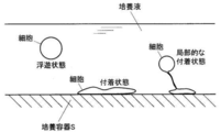
一方、図13に示すように、細胞に粘性があり、細胞の一部が培養容器に付着し、別の一部が培養液中を浮遊しているような状態も存在する。図13は細胞の浮遊状態、付着状態、及び局部的な付着状態を示す説明図である。このような局部的な付着状態の場合、2つの画像間において細胞が同じ位置に存在することがあり、浮遊状態であると判別できない可能性がある。したがって、振動中に撮像した画像を含めた複数の画像を用いて、判別結果を積算することで対応する「複数画像間積算」という方法を適用する。
続いて、この細胞の局部的な付着状態の判別方法である複数画像間積算について、図14~図17を用いて説明する。図14は複数画像間積算の概略説明図、図15は複数画像間積算の詳細説明図、図16は図15の説明図における異なる時点の画像間の同一動領域の特定に係る動作を示すフローチャート、図17は図15の説明図における浮遊領域の追跡と積算に係る動作を示すフローチャートである。
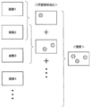
複数画像間積算において、画像処理部5は、図14に示すように振動中に撮像した画像を含めた複数の画像(画像1~4以下)から、図7~図13を用いて説明した浮遊状態にある細胞の判別方法で得られた結果により浮遊とされた領域(浮遊領域、図14中の丸印)を抽出する。さらに、画像処理部5は浮遊領域を抽出した各画像を積算する。これにより、撮像と揺動とのタイミングの同期をとる必要がなく、細胞の付着性にかかわらず浮遊状態、付着状態の判別結果を得ることができる。
複数画像間積算についてさらに詳しく、図15を用いて、図16及び図17に示すフローに沿って説明する。
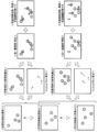
画像処理部5は、図15に示すように連続する2つの浮遊領域抽出画像、例えば画像kと画像k+1を用いて、画像間の差分による動領域(浮遊領域、図15中の丸印)の抽出とオプティカルフローの算出とを行う。そして、これらの結果を用いて、画像処理部5は同一動領域の特定を行う。この同一動領域の特定に係る処理を図16に示すフローに沿って説明する。
なお、浮遊領域抽出画像は次のように生成しても良い。すなわち、時刻t1の画像を基準として時刻t2の画像を補正して浮遊細胞を判別する場合、画像補正部4にて生成する時刻t2’の画像を浮遊領域抽出画像kとする。さらに、時刻t2の画像を基準として時刻t3の画像を補正して浮遊細胞を判別する場合、生成した時刻t3’の画像に対し、時刻t2’の画像を生成する際に用いた補正量をさらに加味して浮遊領域抽出画像k+1とする。以後同様に、前回処理までの補正量を累積することで、時刻t1における付着細胞の位置を基準として時間連続な浮遊領域抽出画像を得ることができる。
画像処理部5は同一動領域の特定に係る処理をスタート(図16のスタート)させると、現画像の特徴点が帰属する動領域をチェックする(ステップ#201)。次に、画像処理部5はチェックした動領域にオプティカルフローによるflowの適用を行う(ステップ#202)。そして、画像処理部5はすべての動領域についてflowの適用が済んだか否かを判別する(ステップ#203)。すべての動領域についてflowの適用が済んでいない場合(ステップ#203のNo)、画像処理部5はステップ#201及び#202の処理を繰り返す。
すべての動領域についてflowの適用が済んだ場合(ステップ#203のYes)、画像処理部5は各動領域に適用したflowをチェックし(ステップ#204)、比較的大きく外れて目立つflowを除外してflowの平均を算出する(ステップ#205)。
次に、画像処理部5は動領域重心からflowの平均分だけ逆方向に移動し、前画像における推定前動領域重心を算出する(ステップ#206)。そして、画像処理部5は推定前動領域重心が別の動領域に内在するかチェックする(ステップ#207)。推定前動領域重心が別の動領域に内在する場合、画像処理部5はそれら動領域を画像間において同一の動領域であると判断し、同一動領域の特定に係る処理を終了する(図16のエンド)。
再び図15に戻り、画像処理部5は同一動領域の特定が済むと、それら動領域を推定浮遊領域とし、推定浮遊領域の追跡と積算を行う。なお、「追跡」とは、画像間で同一の動領域であると特定された推定浮遊領域のさらに時間的に後続する画像における移動先を追うことを意味する。この推定浮遊領域の追跡、積算に係る処
理を図17に示すフローに沿って説明する。
理を図17に示すフローに沿って説明する。
画像処理部5は推定浮遊領域の追跡、積算に係る処理をスタート(図17のスタート)させると、現画像の推定浮遊領域を算出する(ステップ#301)。なお、このステップ#301は図16のフローで説明した処理を意味する。また、「現画像」は図15における連続する2つの浮遊領域抽出画像、例えば画像kと画像k+1の場合の画像k+1を意味する。画像kは後述する「前画像」を意味する。
次に、画像処理部5は現画像の推定浮遊領域をテンプレート化し、ヒストグラムを算出する(ステップ#302)。さらに、画像処理部5はヒストグラムに加えて現画像の推定浮遊領域から得られる領域位置、領域サイズといったテンプレート情報を取得し、浮遊細胞推定データとする(ステップ#303)。浮遊細胞推定データは推定浮遊領域から得られる領域位置、領域サイズ、ヒストグラムなどで構成され、推定浮遊領域の数だけ複数存在する。
そして、画像処理部5は前画像の浮遊細胞結果データを取得する(ステップ#304)。なお、浮遊細胞結果データは前画像の一連の処理の結果、浮遊細胞として計数された領域から得られる領域位置、領域サイズ、ヒストグラムなどで構成され、浮遊細胞として計数された領域の数だけ複数存在する。画像処理部5は浮遊細胞推定データに浮遊細胞結果データを重ね合わせる。
次に、画像処理部5は浮遊細胞結果データの近傍に浮遊細胞推定データがあるか否かを判別する(ステップ#305)。なお、「近傍」の範囲は、例えばこれまでに観察されたflowの最大サイズから算出したり、加振部50を用いて揺動部60に振動を与えたときに設定した加振動作パラメータの振幅から決定したりする。
浮遊細胞結果データの近傍に浮遊細胞推定データがある場合(ステップ#305のYes)、画像処理部5は前画像のその浮遊細胞結果データを破棄する(ステップ#306)。すなわち、画像処理部5は浮遊細胞が前画像の位置から現画像の位置まで移動したとみなして現画像の浮遊細胞推定データを残す。
一方、浮遊細胞結果データの近傍に浮遊細胞推定データがない場合(ステップ#305のNo)、画像処理部5は前画像のその浮遊細胞結果データをそのまま浮遊細胞推定データに追加する(ステップ#307)。すなわち、画像処理部5は前画像で検出されていた浮遊細胞が現画像で検出されなかった場合への対応として浮遊細胞結果データを残す。
ステップ#307の後、画像処理部5は前画像の浮遊細部の動領域についてヒストグラムを生成し、これを用いて近傍を探索して動領域を追跡する(ステップ#308)。なお、「近傍」の範囲は、例えばこれまでに観察されたflowの最大サイズから算出したり、加振部50を用いて揺動部60に振動を与えたときに設定した加振動作パラメータの振幅から決定したりする。そして、画像処理部5はステップ#308で検出された領域情報を用いて、ステップ#307で追加した浮遊細胞推定データを更新する(ステップ#309)。
次に、画像処理部5はステップ#306で残された現画像の浮遊細胞推定データと、ステップ#309で更新された浮遊細胞推定データとを現画像の浮遊細胞結果データとして格納する(ステップ#310)。そして、画像処理部5は推定浮遊領域の追跡を行うべき前画像の浮遊細胞結果データが残っているか否かを判別する(ステップ#311)。前画像の浮遊細胞結果データが残っている場合(ステップ#311のYes)、ステップ#305に戻り、画像処理部5はステップ#305~ステップ#310までの処理を繰り返す。
ステップ#311において前画像の浮遊細胞結果データが残っていない場合(ステップ#311のNo)、画像処理部5は現画像の浮遊細胞結果データを計数して浮遊細胞数とする(ステップ#312)。そして、推定浮遊領域の追跡、積算に係る処理を終了する(図17のエンド)。なお、現画像の浮遊細胞結果データは次回の推定浮遊領域の追跡、積算に係る処理において「前画像の浮遊細胞結果データ」として利用される。
再び図15に戻り、画像処理部5は上記のように推定浮遊領域の追跡、積算の後、浮遊細胞を計数する。すなわち、図15の例では浮遊領域抽出画像kと画像k+1とに関して、細胞A、細胞B、細胞Cの3個の細胞が計数される。
そして、図15に示すように、画像処理部5は浮遊領域抽出画像k+1と画像k+2との画像間についても、同様の処理を実行する。ここで、画像kと画像k+1との画像間で移動したとされる特徴点と、画像k+1と画像k+2との画像間で算出したflowの起点となる特徴点とが同じ領域に存在する場合、画像形成部5はそれらが同じ細胞の動きに帰属すると判断する。すなわち、図15の例では細胞B、細胞Cがこれに該当する。
一方、このような動きをしていないと判断された画像kと画像k+1との画像間で検出された特徴点は画像k+1と画像k+2との画像間で移動しなかったとして、その後浮遊細胞の計数に継続して含める。すなわち、図15の例では細胞Aがこれに該当する。なお、細胞Dは浮遊領域抽出画像k+1と画像k+2との画像間で新たに浮遊状態であると認められた細胞である。
最終的に、浮遊領域抽出画像k、画像k+1、画像k+2の3枚の画像間で、画像処理部5は細胞A~Dの4個が浮遊状態であると判別する。
なお、加振部50の加振動作パラメータを用いて得られた画像処理部5の前回の判別結果に基づき、今回加振部50によって振動させるときの加振動作パラメータを調整しても良い。具体的には、図17のフローによる繰り返し処理中に加振動作パラメータを調整していくことも可能である。画像処理部5の判別結果の例としては浮遊細胞の数や浮遊細胞の振幅などが挙げられ、加振動作パラメータの例としてはモータ55の回転周波数や揺動部60の振幅などが挙げられる。
浮遊細胞や培養容器Sに局部的に付着している細胞の振動具合は未知であるが、加振動作パラメータを調整することによりその影響を受けて振動具合が変動すると考えられる。例えば、細胞の付着状態、浮遊状態の判別を行うための画像処理等では、例えば画像の解像度に対する細胞の振幅が好適な程度で、画像のサンプリングレートに対する細胞の振動周波数が小さい方が好ましいので、そのような振動具合が得られるよう前回の判別結果に基づき今回振動させるときの加振動作パラメータを調整する。
また、同じサンプルに対してより多くの浮遊細胞数が検出できる加振動作パラメータが見つかれば、その設定が浮遊細胞の判別にとって好適であるということになる。なお、これはサンプルを変えればもちろん、同じサンプルでも観察点が異なればその都度、前回の判別結果に基づき今回の加振動作パラメータの設定を調整することが望ましい。
このようにして、培養容器Sに局部的に付着している細胞の振動具合はモータ55の回転周波数や揺動部60の振幅などの影響を受けると考えられるので、加振動作パラメータを調整することにより培養容器Sに局部的に付着している細胞を浮遊細胞として明確に判別するのに好適な振動状況が得られる。
そして、上記実施形態のように振動中の画像を含む複数の異なる時点の画像を用いて画像間の位置ずれを補正するので、細胞が培養容器に局部的に付着している状態と培養容器に完全に付着している状態とが区別される。
本発明の実施形態の構成によれば、複数の異なる時点の画像を用いて培養容器S内における培養液中の細胞の浮遊状態、付着状態を精度よく判別することが可能な撮像装置1を提供することができる。また、培養容器Sに局部的に付着している細胞を浮遊細胞として明確に判別することが可能な撮像装置1を提供することができる。
(第2の実施形態) 次に、本発明の第2の実施形態に係る撮像装置について、図18~図21を用いてその構造を説明する。図18は撮像装置の正面図、図19は撮像装置の構成を示すブロック図、図20は撮像装置の加振部の正面図、図21は加振部の側面図である。なお、この実施形態の基本的な構成は図1~図17を用いて説明した前記第1の実施形態と同じであるので、第1の実施形態と共通する構成について図面の記載及びその説明を省略するものとする。
第2の実施形態に係る撮像装置101は、図18に示すようにその本体102が、床面に対して四箇所に設けられた弾性体たる脚部ゴム107を備える脚部106で支持されている。さらに、本体102はその側面に加振部150を接合して備えている。図18及び図19に示すように、加振部150は脚部ゴム107で支持された本体102を揺動部160として振動させる。
加振部150は、図20~図21に示すようにベース151、レバー152、支軸153、接触片154、モータ155、偏心カム156、スライドガイド157、プッシャ158、及びプッシャバネ159を備えている。
ベース151は前後方向に延びる垂直部151a及び水平部151bを備えた正面から見てL字形状の板状部材で構成されている。このベース151の垂直部151aにて加振部150は本体102に接合している。また、ベース151は左右方向に延びる垂直壁で構成され、垂直部151aと水平部151bとに連結してそれらの構成を補強する補強部151cを備えている。
レバー152は左右方向に向かって延びる形にして、支軸153でベース151の補強部151cに支持されている。支軸153はレバー152の最も外側の端部に設けられている。レバー152は支軸153を中心として垂直面内で回転可能にして支持されている。
接触片154はレバー152の支軸153より内側、すなわち本体102側の箇所に設けられている。接触片154はレバー152に左右方向に向かって延びる形で設けられた長穴152aに対して取り付けられ、この長穴152aに沿って左右方向に取り付け箇所の変更が可能である。また、接触片154はローラ形状をなし、その周面である側面が接触片154の下方に位置するプッシャ158の上端部158aに接触する。
モータ155及び偏心カム156はレバー152の支軸153が設けられた側と反対側の端部、すなわち本体102側の端部近傍に設けられている。モータ155は回転軸線が前後方向に水平をなして補強部151cに固定され、その最前部に偏心カム156が回転可能に取り付けられている。偏心カム156はその回転面が垂直をなし、そのカム形状を有する周面である側面がレバー152の上面に接触する。これにより、モータ155を駆動させて偏心カム156を回転させると、レバー152が支軸153を中心としてその本体102側、すなわち接触片154を上下に変位させるように揺動する。
なお、スライドガイド157がレバー152の本体102側端部の箇所の垂直部151aに設けられている。そして、スライドガイド157の上下方向に延びるガイド溝157a内にレバー152の本体102側端部が収められている。これにより、スライドガイド157はレバー152を上下方向にのみ移動可能に案内し、前後方向への移動を制限している。
プッシャ158は接触片154の下方に配置されている。プッシャ158はベース151の水平部151bを貫通して上下方向に延び、その上端部158aが接触片154に、下端部が床面に当接している。また、プッシャ158は水平部151bに左右方向に向かって延びる形で設けられた長穴151dに対して取り付けられ、この長穴151dに沿って左右方向に取り付け箇所の変更が可能である。
なお、プッシャバネ159がプッシャ158の上端部158aと水平部151bの上面との間に設けられている。プッシャ158の上端部158aを接触片154に、さらにレバー152を偏心カム156に押し付けるようにプッシャバネ159の弾性力が作用しているので、プッシャ158とレバー152とが常に偏心カム156のカム形状に連動して揺動する。
モータ155の駆動によりレバー152が偏心カム156のカム形状に連動して揺動すると接触片154も揺動し、接触片154に接触するプッシャ158の上端部158aとプッシャバネ159を介してベース151の水平部151bが上下方向に押されることとなる。その結果、ベース151が接合された本体102は脚部ゴム107で支持されているので、脚部ゴム107が弾性変形し、本体102が左右にも揺動する。
このようにして、加振部150は揺動部160である本体102に接合され、本体102に振動を与えるように動作する。このとき、加振部150は撮像装置101の脚部106に設けた脚部ゴム107の変位より小さい振幅で振動させる。これにより、加振部150が揺動部160と一緒に振動するので、装置全体が振動する撮像装置101を構成することができる。
また、撮像部110を揺動部160に設けたことにより、容器把持部132と撮像部110とが一緒に揺動部160に設けられていることになるので、容器把持部132と撮像部110とに対して同時に、同じ振動を与えることができる。したがって、培養容器Sと撮像部110との間の相対的な変位を抑制でき、異なる時点の画像間の位置ずれを防止する作用がより高められる。
また、接触片154の取り付け位置を長穴152aに沿って左右方向に変更し、同時にプッシャ158の取り付け位置を長穴151dに沿って左右方向に変更することにより本体102とプッシャ158との相対位置が変更できるので、本体102の振幅が変更可能である。このようにして、加振部150は加振動作パラメータのひとつである本体102の振幅の調整が可能である。
以上、本発明の実施形態につき説明したが、本発明の範囲はこれに限定されるものではなく、発明の主旨を逸脱しない範囲で種々の変更を加えて実施することができる。
例えば、細胞の局部的な付着状態の判別に関して、図15において浮遊領域抽出画像を画像k、画像k+1、画像k+2の3枚用いて判別結果を積算することとしたが、画像は3枚に限定されるわけではなく、2枚または4枚以上であっても構わない。
また、第1の実施形態で揺動部60を支持する弾性体であるゴム34や、第2の実施形態で揺動部160を支持する弾性体である脚部ゴム107は無くても構わない。また、弾性体はゴムに限定されるわけではなく、バネやスポンジなどであっても構わない。
また、本発明の撮像装置1を例えば培養装置に組み込んだ場合、細胞の浮遊状態、付着状態の判別の結果として多寡を評価するものは、上記浮遊細胞数のほか、浮遊細胞率(サンプル中の細胞数に占める浮遊細胞の割合)などを用いても構わない。
本発明は、培養容器内の培養液中の細胞の浮遊状態、付着状態を判別する撮像装置において利用可能である。
1、101 撮像装置
2、102 本体
3、103 制御部
4、104 画像補正部
5、105 画像処理部
10、110 撮像部
20、120 照明部
30、130 ステージ部
31 ホルダ
32、132 容器把持部
34 ゴム(弾性体)
40、140 駆動部
50、150 加振部
60、160 揺動部
106 脚部
107 脚部ゴム(弾性体)
S 培養容器
2、102 本体
3、103 制御部
4、104 画像補正部
5、105 画像処理部
10、110 撮像部
20、120 照明部
30、130 ステージ部
31 ホルダ
32、132 容器把持部
34 ゴム(弾性体)
40、140 駆動部
50、150 加振部
60、160 揺動部
106 脚部
107 脚部ゴム(弾性体)
S 培養容器
Claims (9)
- 細胞と培養液とが入った容器を把持する容器把持部と、
前記容器把持部が設けられた揺動部と、
前記揺動部に振動を与える加振部と、
前記容器内の細胞を画像として撮像する撮像部と、
前記撮像部が撮像した少なくとも一の振動中の画像を含む複数の撮像場所の画像を用いて、撮像場所が異なることにより生じる画像間の位置ずれを補正する画像補正部と、
前記撮像部が撮像した画像と前記画像補正部が補正した画像とを用いて細胞の浮遊状態または付着状態を判別する画像処理部と、
を備えることを特徴とする撮像装置。 - 前記画像補正部は、一の画像における第1の特徴点の位置と、他の画像における前記第1の特徴点に対応する第2の特徴点の位置との差から画像間の位置ずれを識別し、その位置ずれを補正した画像を生成することを特徴とする請求項1に記載の撮像装置。
- 前記画像補正部は、二の画像間で対応する二の特徴点の位置に基づき平行移動、回転移動の画像変換を行うことを特徴とする請求項1または請求項2に記載の撮像装置。
- 前記画像処理部は、三以上の異なる時点の画像を用い、各画像間の差分により導出した画像における細胞の浮遊領域候補を各差分間で追跡、積算することにより細胞の浮遊状態を判別することを特徴とする請求項1~請求項3のいずれか1項に記載の撮像装置。
- 前記揺動部は、弾性体によって支持されていることを特徴とする請求項1~請求項4のいずれか1項に記載の撮像装置。
- 前記加振部は、前記揺動部に接合され、前記弾性体の変位より小さい振幅で振動させることを特徴とする請求項5に記載の撮像装置。
- ホルダにて支持された前記容器把持部を水平方向に移動させるステージ部を備え、
前記加振部は、前記揺動部と前記ホルダとの間に存在する支点によって前記揺動部を振動させることを特徴とする請求項1~請求項6のいずれか1項に記載の撮像装置。 - 前記撮像部は、前記揺動部に設けられることを特徴とする請求項1~請求項6のいずれか1項に記載の撮像装置。
- 前記加振部が加振動作パラメータを調整可能に構成され、前記加振動作パラメータを用いて得られた前記画像処理部の前回の判別結果に基づき今回の前記加振動作パラメータを調整することを特徴とする請求項1~請求項7のいずれか1項に記載の撮像装置。
Priority Applications (1)
| Application Number | Priority Date | Filing Date | Title |
|---|---|---|---|
| US13/731,805 US9106806B2 (en) | 2010-07-28 | 2012-12-31 | Image sensing device |
Applications Claiming Priority (2)
| Application Number | Priority Date | Filing Date | Title |
|---|---|---|---|
| JP2010-169832 | 2010-07-28 | ||
| JP2010169832A JP5691009B2 (ja) | 2010-07-28 | 2010-07-28 | 撮像装置 |
Related Child Applications (1)
| Application Number | Title | Priority Date | Filing Date |
|---|---|---|---|
| US13/731,805 Continuation US9106806B2 (en) | 2010-07-28 | 2012-12-31 | Image sensing device |
Publications (1)
| Publication Number | Publication Date |
|---|---|
| WO2012014756A1 true WO2012014756A1 (ja) | 2012-02-02 |
Family
ID=45529971
Family Applications (1)
| Application Number | Title | Priority Date | Filing Date |
|---|---|---|---|
| PCT/JP2011/066488 Ceased WO2012014756A1 (ja) | 2010-07-28 | 2011-07-20 | 撮像装置 |
Country Status (3)
| Country | Link |
|---|---|
| US (1) | US9106806B2 (ja) |
| JP (1) | JP5691009B2 (ja) |
| WO (1) | WO2012014756A1 (ja) |
Cited By (2)
| Publication number | Priority date | Publication date | Assignee | Title |
|---|---|---|---|---|
| CN103268617A (zh) * | 2013-05-22 | 2013-08-28 | 常熟理工学院 | 一种基于蚁群系统的多细胞多参数的联合估计与精确跟踪系统 |
| JP2021527440A (ja) * | 2018-06-19 | 2021-10-14 | ステムセル テクノロジーズ カナダ インコーポレイテッド | 細胞の自動培養のためのシステム、方法及び装置 |
Families Citing this family (7)
| Publication number | Priority date | Publication date | Assignee | Title |
|---|---|---|---|---|
| CN103210338A (zh) * | 2010-08-30 | 2013-07-17 | 三洋电机株式会社 | 观察装置、观察程序及观察系统 |
| JP6020199B2 (ja) * | 2013-01-24 | 2016-11-02 | 株式会社ソシオネクスト | 画像処理装置、方法、及びプログラム、並びに撮像装置 |
| JP6405603B2 (ja) * | 2013-06-17 | 2018-10-17 | 大日本印刷株式会社 | 情報処理装置、情報処理システム及びプログラム |
| JP6248476B2 (ja) * | 2013-08-29 | 2017-12-20 | 大日本印刷株式会社 | 加振装置 |
| JP6465280B2 (ja) * | 2014-10-31 | 2019-02-06 | 澁谷工業株式会社 | 細胞剥離認識装置および細胞剥離認識方法 |
| US10925579B2 (en) | 2014-11-05 | 2021-02-23 | Otsuka Medical Devices Co., Ltd. | Systems and methods for real-time tracking of a target tissue using imaging before and during therapy delivery |
| CN108251270B (zh) * | 2018-01-16 | 2022-11-15 | 上海睿度光电科技有限公司 | 一种定量溶液覆盖细胞的设备 |
Citations (4)
| Publication number | Priority date | Publication date | Assignee | Title |
|---|---|---|---|---|
| JP2004361086A (ja) * | 2003-05-30 | 2004-12-24 | Olympus Corp | 生体分子解析装置 |
| JP2007275030A (ja) * | 2006-04-12 | 2007-10-25 | Kawasaki Heavy Ind Ltd | 細胞剥離判断方法、培養細胞の剥離方法、細胞剥離判断装置及び自動細胞培養装置 |
| WO2007136073A1 (ja) * | 2006-05-22 | 2007-11-29 | Nikon Corporation | 細胞剥離判定装置、細胞剥離判定方法、および細胞培養装置 |
| JP2009162974A (ja) * | 2008-01-07 | 2009-07-23 | Olympus Corp | 顕微鏡システム及びその制御方法 |
Family Cites Families (4)
| Publication number | Priority date | Publication date | Assignee | Title |
|---|---|---|---|---|
| US5791345A (en) * | 1993-09-03 | 1998-08-11 | Toa Medical Electronics Co., Ltd. | Non-invasive blood analyzer |
| JP2008076088A (ja) * | 2006-09-19 | 2008-04-03 | Foundation For Biomedical Research & Innovation | 細胞のモニター方法およびモニター装置 |
| JP2009089628A (ja) | 2007-10-05 | 2009-04-30 | Nikon Corp | 識別装置および識別方法 |
| US20090143671A1 (en) * | 2007-12-03 | 2009-06-04 | Fujifilm Corporation | Position identifying system, position identifying method, and computer readable medium |
-
2010
- 2010-07-28 JP JP2010169832A patent/JP5691009B2/ja not_active Expired - Fee Related
-
2011
- 2011-07-20 WO PCT/JP2011/066488 patent/WO2012014756A1/ja not_active Ceased
-
2012
- 2012-12-31 US US13/731,805 patent/US9106806B2/en not_active Expired - Fee Related
Patent Citations (4)
| Publication number | Priority date | Publication date | Assignee | Title |
|---|---|---|---|---|
| JP2004361086A (ja) * | 2003-05-30 | 2004-12-24 | Olympus Corp | 生体分子解析装置 |
| JP2007275030A (ja) * | 2006-04-12 | 2007-10-25 | Kawasaki Heavy Ind Ltd | 細胞剥離判断方法、培養細胞の剥離方法、細胞剥離判断装置及び自動細胞培養装置 |
| WO2007136073A1 (ja) * | 2006-05-22 | 2007-11-29 | Nikon Corporation | 細胞剥離判定装置、細胞剥離判定方法、および細胞培養装置 |
| JP2009162974A (ja) * | 2008-01-07 | 2009-07-23 | Olympus Corp | 顕微鏡システム及びその制御方法 |
Cited By (5)
| Publication number | Priority date | Publication date | Assignee | Title |
|---|---|---|---|---|
| CN103268617A (zh) * | 2013-05-22 | 2013-08-28 | 常熟理工学院 | 一种基于蚁群系统的多细胞多参数的联合估计与精确跟踪系统 |
| CN103268617B (zh) * | 2013-05-22 | 2016-02-17 | 常熟理工学院 | 一种基于蚁群系统的多细胞多参数的联合估计与精确跟踪系统 |
| JP2021527440A (ja) * | 2018-06-19 | 2021-10-14 | ステムセル テクノロジーズ カナダ インコーポレイテッド | 細胞の自動培養のためのシステム、方法及び装置 |
| JP2022537441A (ja) * | 2018-06-19 | 2022-08-25 | ステムセル テクノロジーズ カナダ インコーポレイテッド | 細胞培養の適応的継代のためのシステム、方法及び装置 |
| JP7396564B2 (ja) | 2018-06-19 | 2023-12-12 | ステムセル テクノロジーズ カナダ インコーポレイテッド | 細胞の自動培養のためのシステム、方法及び装置 |
Also Published As
| Publication number | Publication date |
|---|---|
| JP2012029584A (ja) | 2012-02-16 |
| JP5691009B2 (ja) | 2015-04-01 |
| US9106806B2 (en) | 2015-08-11 |
| US20130120552A1 (en) | 2013-05-16 |
Similar Documents
| Publication | Publication Date | Title |
|---|---|---|
| JP5691009B2 (ja) | 撮像装置 | |
| JP5778998B2 (ja) | 撮像装置、画像生成方法およびコンピュータプログラム | |
| CN213456719U (zh) | 曲面屏缺陷的检测装置 | |
| EP2288140A3 (en) | Image capture apparatus and method | |
| US8994871B2 (en) | Focus controller | |
| CN100338628C (zh) | 眼睛图像拍摄装置 | |
| CN102547114B (zh) | 摄像设备和镜头单元及其控制方法 | |
| JP6101706B2 (ja) | マシンビジョンシステムにおいて複数の照明設定を使用する合焦点動作 | |
| US20190268545A1 (en) | Focus control device, focus control method, program, and imaging device | |
| CN1812502A (zh) | 图像拾取设备、其照相机主体、以及可互换式透镜 | |
| US9046677B2 (en) | Microscope system and autofocus method | |
| WO2017175783A1 (ja) | 底面位置検出装置、画像取得装置、底面位置検出方法および画像取得方法 | |
| CN1734307A (zh) | 用于图像拍摄设备的系统和方法 | |
| CN100465764C (zh) | 调焦系统、图像获取装置及其控制方法 | |
| JP2017134177A5 (ja) | ||
| JP5448136B2 (ja) | ピックアップ手段選択装置及びピックアップ手段選択方法 | |
| EP1764622A3 (en) | Image pickup apparatus | |
| JP6751144B2 (ja) | 撮像装置、撮像システム及び撮像処理方法 | |
| JP2009223164A (ja) | 顕微鏡画像撮影装置 | |
| EP2957397A2 (en) | Measurement system, object pickup system, measurement method, and carrier means | |
| JP2009109682A (ja) | 自動焦点調節装置、および自動焦点調節方法 | |
| JP6051501B2 (ja) | 固定部材解体システム、固定部材解体方法、およびプログラム | |
| CN1848922A (zh) | 控制设备、控制方法、计算机程序和摄像机 | |
| JPH11287618A (ja) | 画像処理装置 | |
| JP2019097480A (ja) | マニピュレーションシステム及び容器 |
Legal Events
| Date | Code | Title | Description |
|---|---|---|---|
| 121 | Ep: the epo has been informed by wipo that ep was designated in this application |
Ref document number: 11812347 Country of ref document: EP Kind code of ref document: A1 |
|
| NENP | Non-entry into the national phase |
Ref country code: DE |
|
| 122 | Ep: pct application non-entry in european phase |
Ref document number: 11812347 Country of ref document: EP Kind code of ref document: A1 |