WO2012014511A1 - メモリ管理方法、メモリ管理プログラム、計算機 - Google Patents
メモリ管理方法、メモリ管理プログラム、計算機 Download PDFInfo
- Publication number
- WO2012014511A1 WO2012014511A1 PCT/JP2011/054066 JP2011054066W WO2012014511A1 WO 2012014511 A1 WO2012014511 A1 WO 2012014511A1 JP 2011054066 W JP2011054066 W JP 2011054066W WO 2012014511 A1 WO2012014511 A1 WO 2012014511A1
- Authority
- WO
- WIPO (PCT)
- Prior art keywords
- program
- storage capacity
- memory
- reassigned
- allocated
- Prior art date
- Legal status (The legal status is an assumption and is not a legal conclusion. Google has not performed a legal analysis and makes no representation as to the accuracy of the status listed.)
- Ceased
Links
Images











Classifications
-
- G—PHYSICS
- G06—COMPUTING OR CALCULATING; COUNTING
- G06F—ELECTRIC DIGITAL DATA PROCESSING
- G06F9/00—Arrangements for program control, e.g. control units
- G06F9/06—Arrangements for program control, e.g. control units using stored programs, i.e. using an internal store of processing equipment to receive or retain programs
- G06F9/46—Multiprogramming arrangements
- G06F9/50—Allocation of resources, e.g. of the central processing unit [CPU]
- G06F9/5005—Allocation of resources, e.g. of the central processing unit [CPU] to service a request
- G06F9/5011—Allocation of resources, e.g. of the central processing unit [CPU] to service a request the resources being hardware resources other than CPUs, Servers and Terminals
- G06F9/5016—Allocation of resources, e.g. of the central processing unit [CPU] to service a request the resources being hardware resources other than CPUs, Servers and Terminals the resource being the memory
Definitions
- the present invention relates to a technique for managing a memory capacity allocated to a program running on a computer.
- the amount of physical memory allocated to each virtual machine is fixed, the amount of memory that can be used by each virtual machine does not vary. Therefore, the performance of the virtual machine can be easily predicted.
- the setting for allocating the maximum memory capacity used at the peak processing time in a fixed manner is common. Under this setting, at times other than the peak load, a part of the allocated memory is occupied without being used, so that the use of the memory may become inefficient.
- the hypervisor secures a memory capacity pool to be provided for the program running on the virtual machine.
- the hypervisor releases the unused portion of the memory allocated to the virtual machine and returns it to the memory pool.
- the hypervisor can allocate the pooled memory to other virtual machines as needed. Thereby, the memory utilization efficiency as the whole computer improves (refer nonpatent literature 3).
- a process in which one of the two programs decreases the allocated memory amount and the other increases the allocated memory amount between the two programs as described above may be referred to as memory lending.
- a process in which a program that has increased the allocated memory amount after the memory is lent decreases the allocated memory amount, and a program in which the program that has decreased the allocated memory amount increases the allocated memory amount is referred to as memory return.
- lending or returning a process in which one decreases the allocated amount and the other increases the allocated amount
- the lent computer resource is returned as a problem when renting the computer resource. If the resource is not returned, even if the resource usage is less than the prescribed allocation, there may be an unexpected shortage of resources due to lending and performance may be degraded. Therefore, if there is a possibility that the lent computer resources are not returned, it becomes difficult to predict the performance of the virtual machine.
- Patent Document 1 describes a technology for lending resources while guaranteeing return.
- This document relates to lending of network bandwidth, among other resources.
- a program with insufficient bandwidth requests a loan to another program, and a program with an unused bandwidth returns a response including the loan amount.
- each program records information on the lender and loan amount.
- the lending source transmits a lending end notification, and the lending destination reduces the communication amount accordingly and returns the lent resources.
- Garbage collection determines whether there is a possibility of being used from a program for each object in the memory, and collects objects that are not likely to be used (hereinafter referred to as garbage objects). Garbage collection is used in a Java (registered trademark) virtual machine (Java VM) or the like.
- the basic garbage collection process traces the object reference relationship in memory based on the object group (reference route) that the program will surely use, and determines that the object that could not reach the end is a garbage object. This is implemented by collecting the determined garbage object (see Non-Patent Document 1).
- Data compression is to detect various redundancy contained in the data and eliminate the redundancy to convert the data to other data with a small storage capacity while maintaining the contents of the data.
- Non-Patent Document 3 there is a memory paging process.
- data in the memory is saved in another storage medium such as a magnetic disk.
- the saved data becomes necessary again, the data can be restored on the memory by copying the data from the save destination storage medium to the memory again.
- This paging process eliminates the need to keep the data on the memory, thereby reducing the memory usage.
- Some hypervisors provide a paging process for a memory used by a virtual machine (see Non-Patent Document 3).
- Garbage Collection Algorithms Dynamics Memory Management (Richard Jones, Rafael Lins, 1996, John Wiley & Sons Inc, ISBN: 978-0471941484) Introduction to Data Compression, Third Edition (Khalid Sayood, 2005, Morgan Kaufmann, ISBN: 978-0126208627) Carl A. Waldspurger, Memory resource management in VMware ESX server, ACM SIGOPS Operating Systems Review Volume 36, Issue SI (Winter 2002), p.181-194
- Non-Patent Documents 1 to 3 cited as technologies for reducing the memory usage require a certain amount of execution time. Therefore, when the side that lent the memory capacity requests to return the memory capacity, it takes time until the memory capacity is returned, and there is a possibility that the lent side will be short of memory capacity.
- the present invention has been made to solve the above-described problems, and an object of the present invention is to provide a memory management technique for realizing appropriate dynamic allocation of memory capacity between programs.
- memory capacity is allocated to the first program and the second program that run on the computer.
- the memory capacity allocated to the second program is reassigned (lent) to the first program.
- a memory allocation return request (return request) to the first program at a timing when the memory capacity is allocated (returned) from the first program to the second program before the memory capacity used by the second program is insufficient. To be notified.
- the memory management method according to the present invention can appropriately perform dynamic allocation of memory capacity between programs.
- FIG. 3 is a functional block diagram of a computer 100 according to Embodiment 1.
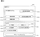
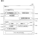
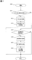
- FIG. It is a figure which shows the detailed structure of 140 A of virtual machines. It is a figure which shows the detailed structure of the virtual machine 140B. It is a figure which shows the structure and data example of loan information management table 1411B. It is a figure which shows the process sequence which borrows and borrows memory capacity between the memory management programs 141A and 141B. It is a figure which shows the processing flow of the memory management program 141A in the sequence diagram of FIG. It is a figure which shows the processing flow of the memory management program 141B in the sequence diagram of FIG. It is a flowchart explaining the detailed process in step S205.
- FIG. 10 is a functional block diagram of a computer 100 according to a third embodiment. It is a figure which shows the detailed structure of 140 A of virtual machines in Embodiment 3. FIG. It is a figure which shows the structure and data example of the loan information management table 1411B in Embodiment 3. It is a flowchart explaining the detailed process in step S205.
- FIG. 10 is a functional block diagram of a computer 100 according to a fourth embodiment.
- FIG. 14 is a flowchart for describing detailed processing of step S205 in the fourth embodiment.
- FIG. 1 is a functional block diagram of a computer 100 according to the first embodiment of the present invention.
- the computer 100 is a computer that executes Java VM 142A (first program) and Java VM 142B (second program).
- Java VM 142A first program
- Java VM 142B second program
- memory capacity is lent from the Java VM 142B to the Java VM 142A.
- the computer 100 includes a CPU 110, a storage unit 120, a memory 130, and a hypervisor 150.
- the CPU 110 executes the hypervisor 150 in a storage area on the memory 130.
- virtual machines 140A and 140B are created under the hypervisor 150.
- the virtual machines 140A and 140B have substantially the same configuration, when they are collectively referred to, the subscripts are omitted and referred to as the virtual machine 140. Similarly, for each component under the virtual machine, subscripts are omitted when describing common items generically.
- each program such as the hypervisor 150, the virtual machine 140, and the memory management program 141 may be described as an operation subject. However, these programs are actually executed by an arithmetic device such as the CPU 110. Let me add that.
- the hypervisor 150 configures virtual machines 140A and 140B on the memory 130.
- the hypervisor 150 allocates the resources included in the computer 100, that is, the CPU 110, the storage unit 120, and the memory 130 to each virtual machine.
- the amount of allocation is set in advance by the operation manager of the computer 100.
- the virtual machines 140A and 140B emulate a computer using each computer resource allocated from the hypervisor 150, and operate as a virtual computer. Although two virtual machines are illustrated here, the number of virtual machines may be arbitrary. Further, the number of virtual machines to be a memory lending source and a memory lending destination to be described later may be arbitrary.
- the memory management program 141A, JavaVM 142A, and operating system 143A operate under the virtual machine 140A.
- the memory management program 141B, JavaVM 142B, and operating system 143B operate.
- the memory management program 141A requests the memory management program 141B to lend memory capacity.
- the memory management program 141B lends a memory area not used by the JavaVM 142B to the memory management program 141A, and requests to return it when it becomes necessary. Details of these operations will be described later.
- the hypervisor 150 since the hypervisor 150 manages the resources of the computer 100, it is added that the memory management program 141 lends and borrows memory capacity via the hypervisor 150.
- the operating systems 143A and 143B are computer operating systems emulated by the virtual machines 140A and 140B, respectively.
- the Java VM 142A and the Java VM 142B are application programs that operate in response to allocation of memory capacity from each virtual machine.
- FIG. 2 is a diagram showing a detailed configuration of the virtual machine 140A.
- the memory management program 141A includes a notification reception unit 1412A, an information transmission unit 1413A, a loan request transmission unit 1414A, and a loan request opportunity determination unit 1416A. Each of these functional units can be implemented in the form of a software module under the memory management program 141A.
- the notification receiving unit 1412A receives a notification from the memory management program 141B.
- the information transmission unit 1413A transmits information such as the setting parameters of the Java VM 142A to the memory management program 142B.
- the lending request timing determination unit 1416A determines a timing (timing) that should be requested to the memory management program 142B to lend the memory capacity.
- the loan request transmission unit 1414A requests the memory management program 142B to lend the memory capacity according to the trigger determined by the loan request trigger determination unit 1416A.
- the Java VM 142A includes a heap area 1421A, a GC processing unit 1422A, a memory allocation changing unit 1423A, a reference route 1424A, and a Java program execution unit 1425A.
- the Java program execution unit 1425A reads the Java program 121 from the storage unit 120 and executes it.
- the Java program execution unit 1425A secures an object required in the middle of executing the Java program 121 in the heap area 1421A.
- the Java program execution unit 1425A stores the reference route for the object in the heap area 1421A in the reference route 1424A, and operates the object.
- GC processing unit 1422A specifies an unused object by tracing the reference relationship of the object stored in reference route 1424A, and releases the corresponding memory area. Therefore, the processing time of the GC processing unit 1422A increases as the amount of memory to be subjected to GC processing increases.
- the processing time by the GC processing unit 1422A is substantially proportional to the target memory amount, and when the return request should be issued based on the GC processing time per unit memory amount and the target memory amount. judge. Details will be described later.
- FIG. 3 is a diagram showing a detailed configuration of the virtual machine 140B.
- the memory management program 141B includes a lending information management table 1411B, a notification reception unit 1412B, a return request transmission unit 1415B, and a return request opportunity determination unit 1417B. Each of these functional units can be implemented in the form of a software module under the memory management program 141B.
- the lending information management table 1411B is a data table that stores information related to the JavaVM 142A. Details will be described later with reference to FIG.
- the notification receiving unit 1412B receives a notification from the memory management program 141A.
- the return request trigger determination unit 1417B determines a trigger to request to return the lent memory capacity.
- the return request transmission unit 1415B requests the memory management program 142A to return the memory capacity according to the trigger determined by the return request trigger determination unit 1417B.
- FIG. 4 is a diagram showing a configuration and data example of the loan information management table 1411B.
- the lending information management table 1411B is a data table that stores information related to memory capacity lending and borrowing, and includes a lending amount field 14111B, a lending destination memory total amount field 14112B, and a GC processing speed field 14113B.
- the loan amount field 14111B holds the value of the memory capacity that the Java VM 142B lends to the Java VM 142A.
- the lending destination memory total amount field 14112B holds the value of the total amount of memory used at the lending destination of the memory capacity.
- the capacity of the heap area 1421A of the Java VM 142A corresponds.
- This field is provided in view of the necessity of performing GC processing when the Java VM 142A returns the memory capacity borrowed from the Java VM 142B. Since the execution time of the GC process depends on the size of the heap area 1421A to be released, this field is provided to be used for predicting the release time.
- the GC processing speed field 14113B holds the time required for the GC processing unit 1422A of the Java VM 142A to perform the GC processing on the unit memory amount (here, MB) of the heap area 1421A.
- the time required for the GC processing unit 1422A of the Java VM 142A to release the heap area 1421A by the GC processing can be known. In the first embodiment, this time is regarded as the time required to return the memory capacity borrowed by the JavaVM 142A.
- the memory management program 141B issues a memory return request to the memory management program 141A, the memory management program 141B issues a return request early in consideration of this time.
- the “allocation unit” and “return unit” in the first embodiment correspond to the memory management programs 141A and 141B and the CPU 110 that executes them.
- the configuration of the computer 100 according to the first embodiment has been described above. Next, the overall operation of the computer 100 and the operation of lending and borrowing memory capacity between the memory management programs 141 will be described.
- the operation manager of the computer 100 instructs the hypervisor 150 to generate the virtual machine 140A and the virtual machine 140B on the memory 130.
- the operation manager activates the operating system 143A on the virtual machine 140A and executes the Java VM 142A.
- the operation manager activates the operating system 143B on the virtual machine 140B and executes the Java VM 142B.
- the information transmission unit 1413A notifies the notification reception unit 1412B of the size of the heap area 1421A and the time required for the GC processing per unit memory amount by the GC processing unit 1422A when the Java VM 142A is activated. These values are specified in advance by an operation manager or the like and described in the setting file of the Java VM 142 or the like.
- the information transmitting unit 1413A may cause the GC processing unit 1422A to execute the GC process and notify the notification receiving unit 1412B of the processing time measured at that time.
- the notification receiving unit 1412B stores the contents in each field of the loan information management table 1411B.
- the information transmission unit 1413A may notify each of the above information at predetermined time intervals while the Java VM 142A is operating instead of or in combination with the Java VM 142A being activated.
- FIG. 5 is a diagram showing a processing sequence for lending and borrowing memory capacity between the memory management programs 141A and 141B.
- a step number 100 is assigned to the process on the virtual machine 140A side
- a step number 200 is assigned to the process on the virtual machine 140B side.
- the lending request opportunity determination unit 1416A compares the free capacity of the heap area 1421A with a predetermined threshold at predetermined time intervals, and if the free capacity is below the threshold, an opportunity to issue a memory lending request to the memory management program 141B. It is determined that Alternatively, when the free space in the heap area 1421A is reduced by the processing of the Java program execution unit 1425A, the Java VM 142A requests the loan request trigger determination unit 1416A to determine whether or not to issue a memory loan request. Good.
- Step S101 Supplement
- the method of determining the opportunity of the loan request in this step is not limited to the method of comparing the free capacity of the heap area 1421A and the threshold value.
- Step S102 The loan request transmission unit 1414A notifies the notification reception unit 1412B of the loan request.
- the amount of memory requested to lend may be described in the lending request.
- the notification receiving unit 1412B receives the loan request transmitted by the loan request transmitting unit 1414A.
- the notification receiving unit 1412B requests the Java VM 142B to reduce the amount of use of the heap area 1421B.
- the memory allocation changing unit 1423B of the Java VM 142B decreases the size of the heap area 1421B.
- the memory allocation changing unit 130B determines the amount by which the size of the heap area 1421B is decreased based on the amount by which the heap area 1421B is used. Alternatively, when the amount of memory to be lent is specified in the loan request transmitted by the loan request transmitter 1414A, the size reduction amount of the heap area 1421B may be determined based on the amount.
- Step S202 Supplement
- the memory allocation changing unit 1423B reduces the size of the heap area 1421B, if there is a necessary process such as restarting the Java VM 142B, the memory allocation changing unit 1423B executes it appropriately.
- the reduced amount of the heap area 1421B is returned to the memory pool of the hypervisor 150. It will be.
- Step S203 After decreasing the size of the heap area 1421B, the notification receiving unit 1412B returns a response including the size reduction amount of the heap area 1421B to the lending request transmitting unit 1414A. At this time, the notification receiving unit 1412B increases the value of the loan amount field 14111B of the loan information management table 1411B by the size reduction amount of the heap area 1421B.
- the loan request transmission unit 1414A receives the response transmitted by the notification reception unit 1412B.
- the loan request transmission unit 1414A instructs the Java VM 142A to increase the size of the heap area 1421A.
- Step S104 The memory allocation changing unit 1423A of the Java VM 142A increases the size of the heap area 1421A by the amount corresponding to the memory capacity increased in step S202. When this step is completed, the memory capacity allocated to the JavaVM 142B is temporarily reassigned to the JavaVM 142A.
- Step S104 Supplement
- the memory allocation changing unit 1423A When there is a necessary process such as restarting the Java VM 142A when the size of the heap area 1421A is increased, the memory allocation changing unit 1423A appropriately executes it.
- the increase in the size of the heap area 1421A is allocated from the memory pool of the hypervisor 150. become.
- Steps S105 and S204 The Java VMs 142A and 142B execute the Java program 121.
- the return request opportunity determination unit 1417B determines whether or not it should be requested to return the memory capacity lent to the memory management program 141A at predetermined time intervals. Alternatively, when the free capacity of the heap area 1421B is reduced by the processing of the Java program execution unit 1425B, the Java VM 142B requests the return request trigger determination unit 1417B to determine whether or not to issue a memory return request. Good.
- the return request transmission unit 1415B transmits the return request to the notification reception unit 1412A when the return request trigger determination unit 1417B determines that the return request should be transmitted.
- an amount of memory requesting return may be specified.
- the notification receiving unit 1412A receives the return request transmitted by the return request transmitting unit 1415B.
- the notification receiving unit 1412A requests the Java VM 142A to reduce the amount of use of the heap area 1421A.
- Step S107 The GC processing unit 1422A of the Java VM 142A performs GC processing on the heap area 1421A.
- the memory allocation changing unit 1423A decreases the size of the heap area 1421A.
- Step S108 The notification reception unit 1412A returns a response including the size reduction amount of the heap area 1421A to the return request transmission unit 1415B.
- the return request transmission unit 1415B receives the response transmitted by the notification reception unit 1412A.
- the return request transmission unit 1415B instructs the Java VM 142B to increase the size of the heap area 1421B.
- the value of the loan amount field 14111B of the loan information management table 1411B is decreased by the size reduction amount of the heap area 1421A.
- Step S208 The memory allocation changing unit 1423B of the Java VM 142B increases the size of the heap area 1421B by the size reduction amount of the heap area 1421A.
- the memory capacity temporarily reassigned to the Java VM 142A is reassigned to the Java VM 142B.
- FIG. 6 is a diagram showing a processing flow of the memory management program 141A in the sequence diagram of FIG. Hereinafter, each step of FIG. 6 will be described. In addition, the same step number was provided about the same step as FIG.
- the memory management program 141A has a predetermined timing such as a predetermined time interval, a time when the Java VM 142A requests an opportunity determination from the lending request timing determination unit 1416A, or a time when the notification reception unit 1412A receives a memory return request from the return request transmission unit 1415B. This processing flow is started.
- Step S106 The memory management program 141A determines whether a memory return request has been received from the return request transmission unit 1415B. If received, the process proceeds to step S107. If not received, the process skips to step S101.
- the memory management program 141A decreases the size of the heap area 1421A and returns the corresponding memory capacity (S107).
- the memory management program 141A returns a response to the return request transmission unit 1415B (S108).
- Step S101 The memory management program 141A determines whether or not the amount of memory used by the JavaVM 142A is insufficient. The determination method is as described in step S101 in FIG. When it is determined that the memory is insufficient, the process proceeds to step S102, and when it is determined that the memory is not insufficient, the process flow ends.
- the memory management program 141A transmits a memory lending request to the notification receiving unit 1412B (S102).
- the memory management program 141A receives a response from the notification receiving unit 1412B (S103)
- the memory management program 141A increases the size of the heap area 1421A (S104).
- FIG. 7 is a diagram showing a processing flow of the memory management program 141B in the sequence diagram of FIG. Hereinafter, each step of FIG. 7 will be described. In addition, the same step number was provided about the same step as FIG.
- the memory management program 141B is configured at a predetermined timing such as a predetermined time interval, a time when the Java VM 142B requests the return request trigger determination unit 1416B to determine a trigger, or a time when the notification reception unit 1412B receives a notification from the loan request transmission unit 1414A. Start the processing flow.
- Step S201 The memory management program 141B determines whether or not a memory lending request has been received from the lending request transmission unit 1414A. If received, the process proceeds to step S202. If not received, the process skips to step S205.
- the memory management program 141B reduces the size of the heap area 1421B and lends the corresponding memory capacity (S202).
- the memory management program 141B returns a response to the return request transmission unit 1414A (S203).
- Step S205 The memory management program 141B determines whether or not it is an opportunity to transmit a return request. If it is determined that the return request is transmitted, the process proceeds to step S206. If it is determined that the return request is not transmitted, the process flow ends.
- the memory management program 141B transmits a memory return request to the notification receiving unit 1412A (S206).
- the memory management program 141B receives a response from the notification receiving unit 1412A (S207)
- the memory management program 141B increases the size of the heap area 1421B (S208).
- FIG. 8 is a flowchart for explaining detailed processing in step S205. Hereinafter, each step of FIG. 8 will be described.
- the return request opportunity determination unit 1417B sets the return request opportunity flag to an invalid value (for example, “0”).
- the return request trigger flag is a flag indicating whether or not a trigger for issuing a return request has been reached.
- the return request opportunity determination unit 1417B stores the value of the flag in an appropriate storage area in the memory 120, for example.
- the return request opportunity determination unit 1417B reads the value of the GC processing speed field 14113B of the loan information management table 1411B and stores it in the variable y.
- the return request opportunity determination unit 1417B reads the value of the loan destination memory total amount field 14112B of the loan information management table 1411B and stores it in the variable z.
- the return request opportunity determination unit 1417B acquires the free capacity of the heap area 1421B of the Java VM 142B and stores it in the variable m.
- the return request opportunity determination unit 1417B calculates the amount by which the free capacity of the heap area 1421B decreases per unit time, and stores it in the variable n. Specifically, the return request opportunity determination unit 1417B obtains a difference between the free capacity of the heap area 1421B acquired when the step S2054 was executed last time and the free capacity of the heap area 1421B acquired when the execution was performed this time, and the previous execution time Divide by the elapsed time from.
- Step S2055 Supplement
- the return request opportunity determination unit 1417B executes step S2054 for the first time
- the size of the heap area 1421B can be used instead of the free space at the previous processing
- the elapsed time from the start of the Java VM 142B to the current time can be used instead of the elapsed time from the previous processing.
- Step S2056 The return request opportunity determination unit 1417B determines whether or not the following formula (1) is satisfied. If it is established, the process proceeds to step S2057, and if it is not established, this flowchart is terminated. z ⁇ y ⁇ m / n (1)
- the left side (“z ⁇ y”) of Expression (1) is obtained by multiplying the total memory amount (z) to be GC-targeted by the GC processing time (y) per unit memory amount. This represents the time required to perform the GC process on the heap area 1421A of the Java VM 142A.
- the right side (“m / n”) of Expression (1) is obtained by dividing the free capacity (m) of the heap area 1421B by the amount (n) by which the free capacity of the heap area 1421B decreases per unit time. This represents the time until there is no more free space in the heap area 1421B.
- the time required to release the heap area 1421A is longer (or both are equal) than the time until the heap area 1421B has no free space. In this case, if the return request is not sent immediately, the heap area 1421B will be depleted of free area. Therefore, the return request trigger determination unit 1417B determines that the trigger for transmitting the return request has been reached.
- the determination formula used by the return request trigger determination unit 1417B for trigger determination is not limited to Formula (1).
- the time required for the memory allocation changing unit 1423 to change the size of the heap area 1421 is so long that it cannot be ignored, the time required for the size changing process may be added to the left side of Expression (1).
- Expression (1) depending on the execution timing of step S205, the time required to release the heap area 1421A is longer than the time until there is no free area in the heap area 1421B at the time of determining the trigger. There is a risk that it will not be returned in time. Therefore, a value representing a safety coefficient may be added to the left side of the equation (1).
- Step S2057 The return request opportunity determination unit 1417B sets the return opportunity flag to a valid value (eg, “1”), and ends this flowchart.
- the memory management program 141B is configured so that the memory space used by the Java VM 142B is not exhausted on the assumption that the Java VM 142A needs time to execute the GC. A memory return request is transmitted to the management program 141A. Thereby, even if it takes time to return the memory capacity lent to the Java VM 142A, the possibility of reducing the performance of the Java VM 142B can be reduced.
- the memory management program 141A that borrows memory capacity is arranged in the virtual machine 140A
- the memory management program 141B that lends memory capacity is arranged in the virtual machine 140B, but one virtual machine 140 is arranged.
- Both of the memory management programs 141 can be arranged at the same time.
- the Java VM 142 can lend or borrow memory capacity. The same applies to the following embodiments.
- the example in which the memory capacity is lent and borrowed between the two JavaVMs 142 has been described. Even when the memory capacity is lent and borrowed between three or more JavaVMs 142, the same technique as in the first embodiment is used. Can do. The same applies to the following embodiments.
- the memory management program 141 and the Java VM 142 can also be configured integrally.
- the memory management programs 141A and 141B can be integrally configured to have both a function of borrowing memory capacity and a function of lending. The same applies to the following embodiments.
- the trigger for issuing the return request is determined on the assumption that the GC processing time is proportional to the total memory capacity of the GC target.
- the present invention is not necessarily limited to this. Other methods that can estimate the GC processing time can also be adopted. The same applies to the following embodiments.
- the Java VM 142 is used as a program for lending and borrowing memory capacity.
- a program to which the present invention can be applied is not limited to the Java VM.
- the present invention can also be applied to other programs that use memory capacity. The same applies to the following embodiments.
- the memory capacity return by the GC processing used in the first embodiment if most of the heap area 1421A is occupied by objects that are not garbage objects (hereinafter, non-garbage objects), the memory capacity may not be reduced sufficiently. . If the memory capacity cannot be reduced sufficiently, even if a return request is issued when the GC processing time is taken into consideration, the memory capacity cannot be returned until the Java VM 142B needs the memory capacity, and the performance of the Java VM 142B decreases. There is a fear.
- the processing time increases as the amount of memory to be processed increases.
- the processing time required for data compression is almost proportional to the target memory amount, and an opportunity to send a memory return request based on the data compression processing time per unit memory amount and the processing target memory amount. judge.
- FIG. 9 is a diagram illustrating a detailed configuration of the virtual machine 140A according to the second embodiment.
- the Java VM 142A newly includes a data compression processing unit 1426A in addition to the configuration described in FIG. 2 of the first embodiment.
- Other configurations of the virtual machine 140A are the same as those in the first embodiment. The operation of the data compression processing unit 1426A will be described later.
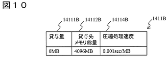
- FIG. 10 is a diagram illustrating a configuration and data example of the loan information management table 1411B according to the second embodiment.
- the configuration of the virtual machine 140B is substantially the same as that of the first embodiment, but the configuration of the loan information management table 1411B is different.
- the lending information management table 1411B has a compression processing speed field 14114B instead of the GC processing speed field 14113B.
- the compression processing speed field 14114B holds the time required for the data compression processing unit 1426A of the Java VM 142A to perform the data compression processing on the unit memory amount (here, MB) of the heap area 1421A.
- the configuration of the computer 100 according to the second embodiment has been described above. Next, the overall operation of the computer 100 and the operation of lending and borrowing memory capacity between the memory management programs 141 will be described.
- the information transmission unit 1413A When the Java VM 142A is activated, the information transmission unit 1413A notifies the notification reception unit 1412B of the size of the heap area 1421A and the time required for the data compression processing unit 1426A to perform data compression processing per unit memory amount. These values are specified in advance by an operation manager or the like. Alternatively, the information transmission unit 1413A may cause the data compression processing unit 1426A to execute data compression processing and notify the notification reception unit 1412B of the processing time measured at that time. Upon receiving the notification, the notification receiving unit 1412B stores the contents in each field of the loan information management table 1411B.
- the information transmission unit 1413A may notify each of the above information at predetermined time intervals while the Java VM 142A is operating instead of or in combination with the Java VM 142A being activated.
- the data compression processing unit 1426A compresses the data in the heap area 1421A, thereby reducing the amount of memory used by the JavaVM 142A. At this time, only data with a low use frequency may be compressed based on the use frequency of the data. Alternatively, the data amount after compression may be predicted, and only data with a high data amount reduction effect may be compressed.
- the data compression processing unit 1426A can use any compression algorithm.
- the memory allocation changing unit 1423A decreases the size of the heap area 1421A.
- FIG. 11 is a flowchart for explaining detailed processing in step S205.
- the processing in step S205 is different from the content in step S2052 described in FIG.
- the other steps are the same as in FIG.
- Step S2052 The return request opportunity determination unit 1417B reads the value of the compression processing speed field 14114B of the loan information management table 1411B and stores it in the variable y.
- Step S2056 This step in the second embodiment compares the time required for compressing the data in the heap area 1421A of the Java VM 142A with the expected time required until the heap area 1421B of the Java VM 142B is exhausted.
- the trigger for issuing the return request is determined on the assumption that the data compression processing time is proportional to the total memory to be compressed.
- the present invention is not necessarily limited to this. Other methods that can estimate the data compression processing time can also be adopted. The same applies to other embodiments.
- memory usage reduction by data compression processing and memory usage reduction by GC processing can be used in combination. For example, first, a GC process is performed to reduce the memory usage, and when the reduction amount is insufficient, a data compression process is additionally performed.
- the memory usage is performed by the paging function of the hypervisor 150 in place of or in combination with the GC processing of the Java VM 142 described in the first embodiment and the data compression processing described in the second embodiment.
- a method for reducing the amount will be described. Since the overall configuration of the computer 100 is the same as that of the first embodiment, the following description will focus on differences.
- the memory usage when the memory usage is reduced by the paging function, the memory usage can be reduced regardless of the degree of non-garbage objects and redundancy in the heap area 1421, and the above problem does not occur.
- the paging process is performed by copying the data in the memory to another storage medium. Therefore, a processing time almost proportional to the memory amount to be paging is required.
- a trigger for issuing a memory return request is determined based on the paging processing time per unit memory amount and the target memory amount.
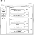
- FIG. 12 is a functional block diagram of the computer 100 according to the third embodiment.
- the hypervisor 150 of the computer 100 includes a paging processing unit 151. Since other configurations are substantially the same as those in the first and second embodiments, the following description will focus on differences.
- the paging processing unit 151 replicates data in the memory 130 used by each virtual machine 140 to another storage medium (for example, the storage unit 120) by paging processing.
- FIG. 13 is a diagram illustrating a detailed configuration of the virtual machine 140A according to the third embodiment.
- the memory management program 141A includes a paging request unit 1418A in addition to the configuration described in the first and second embodiments.
- the paging request unit 1418A can be implemented in the form of a software module under the memory management program 141A.
- the paging request unit 1418A requests the hypervisor 150 to execute paging processing. Through the paging process, the amount of memory used by the virtual machine 140A is reduced. Note that only the heap area 1421A may be a target for reducing the memory usage.
- FIG. 14 is a diagram illustrating a configuration and data example of the loan information management table 1411B according to the third embodiment.
- the configuration of the virtual machine 140B is substantially the same as that of the first embodiment, but the configuration of the loan information management table 1411B is different.
- the lending information management table 1411B has a paging processing speed field 14115B instead of the GC processing speed field 14113B. When paging processing is performed only on the amount of memory that is lent, the lent destination memory total amount field 14112B can be omitted.
- the paging processing speed field 14115B holds the time required for the paging processing unit 151 of the hypervisor 150 to perform paging processing on the unit memory amount (here, MB) of the memory 130.
- the time required for the paging processing unit 151 of the hypervisor 150 to compress the objects in the heap area 1421A and reduce the memory usage amount is regarded as the time required to return the memory capacity borrowed by the JavaVM 142A.
- the configuration of the computer 100 according to the third embodiment has been described above. Next, the overall operation of the computer 100 and the operation of lending and borrowing memory capacity between the memory management programs 141 will be described.
- the information transmitting unit 1413A notifies the notification receiving unit 1412B of the time required for the paging processing per unit memory amount to the notification receiving unit 1412B when the Java VM 142A is activated. These values are specified in advance by an operation manager or the like. Alternatively, the information transmitting unit 1413A may cause the paging processing unit 151 to execute the paging process and notify the notification receiving unit 1412B of the processing time measured at that time. Upon receiving the notification, the notification receiving unit 1412B stores the contents in the corresponding field of the loan information management table 1411B.
- the information transmission unit 1413A may notify each of the above information at predetermined time intervals while the Java VM 142A is operating instead of or in combination with the Java VM 142A being activated.
- the paging request unit 1418A requests the paging processing unit 151 to execute paging.
- the paging processing unit 151 performs paging processing on the memory area allocated to the virtual machine 140A. At this time, the paging process may be preferentially performed on the memory area allocated to the heap area 1421A. Further, it is not always necessary to perform the paging process for all the memory areas allocated to the virtual machine 140A or the heap area 1421A, and the paging process may be performed only for a part of the memory areas.
- the memory allocation changing unit 1423A decreases the size of the heap area 1421A.
- FIG. 15 is a flowchart for explaining detailed processing in step S205.
- the contents of steps S2052 to S2053 described in FIG. The other steps are the same as in FIG.
- the return request opportunity determination unit 1417B reads the value of the paging processing speed field 14115B of the loan information management table 1411B and stores it in the variable y.
- the return request opportunity determination unit 1417B reads the value of the loan amount field 14111B of the loan information management table 1411B and stores it in the variable z.
- Step S2056 This step in the third embodiment compares the time required for paging processing corresponding to the memory capacity borrowed by the Java VM 142A and the expected time required for the heap area 1421B of the Java VM 142B to be exhausted. .
- the memory capacity used by the Java VM 142A can be reduced even when the data in the heap area 1421A is not very redundant. As a result, the memory capacity can be lent to the Java VM 142A while more reliably suppressing the possibility that the performance of the Java VM 142B will deteriorate.
- the memory management program 141A includes the paging request unit 1418A.
- the memory management program 141B may be configured to include the paging request unit 1418A.
- a paging process is requested from the memory management program 141B for the memory capacity allocated to the virtual machine 140A or the heap area 1421A.
- the memory capacity borrowed by the Java VM 142 can be returned.
- the memory management program 141 includes the paging request unit 1418.
- a program other than the memory management program 141 may include the paging request unit 1418. .
- the GC processing is first performed to reduce the memory usage, the data compression processing is performed if the reduction amount is insufficient, and the paging is performed when the reduction amount is insufficient. Conceivable.
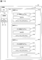
- FIG. 16 is a functional block diagram of the computer 100 according to the fourth embodiment.
- the computer 100 includes three virtual machines 140A, 140B, and 140C.
- the detailed configuration of the virtual machine 140C will be described later. Since other configurations are substantially the same as those in the first to third embodiments, the following description will focus on differences.
- the JavaVM 142A cannot return the memory capacity borrowed from the JavaVM 142B because it is in use or the like, the JavaVM 142C borrows the memory capacity from the JavaVM 142C and returns it to the JavaVM 142B. Thereby, even when the Java VM 142A receives a memory return request from the Java VM 142B, the Java VM 142A can continue to operate without reducing the memory capacity to be used. That is, the memory usage efficiency of the computer 100 as a whole is improved by making available memory capacity interchangeable among a plurality of virtual machines 140.
- FIG. 17 is a diagram illustrating a detailed configuration of the virtual machine 140B according to the fourth embodiment.
- the memory management program 141B includes a loanable amount transmitting / receiving unit 1419B in addition to the configurations described in the first to third embodiments.
- the loanable amount transmitting / receiving unit 1419B can be implemented in the form of a software module under the memory management program 141B.
- FIG. 17 illustrates the configuration including the lent amount transmission / reception unit 1419B in addition to the configuration described in FIG. 3 of the first embodiment. However, in addition to the configuration of the memory management program 141B in other embodiments, lent amount transmission / reception is performed. A portion 1419B can also be provided.
- the lent amount transmission / reception unit 1419B receives the value of the memory capacity that can be lent by the JavaVM 142C from the lent amount transmission / reception unit 1419C described later. This value is stored in the loan information management table 141B described in FIG.
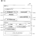
- FIG. 18 is a diagram showing a detailed configuration of the virtual machine 140C. Since the virtual machine 140C lends memory capacity to the virtual machine 140A, the configuration is substantially the same as that of the virtual machine 140B. The configuration of the loan information management table 1411C is the same as that described with reference to FIG.
- the lent amount transmission / reception unit 1419C transmits the value of the memory capacity that can be lent by the Java VM 142C to the lent amount transmission / reception unit 1419B of the memory management program 141B.
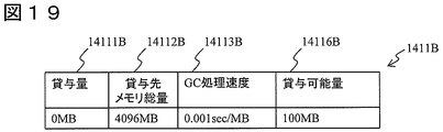
- FIG. 19 is a diagram showing a configuration and data example of the loan information management table 1411B according to the fourth embodiment.
- the lending information management table 1411B according to the fourth embodiment has a new lendable amount field 14116B in addition to the configuration described in the first to third embodiments.
- the lent amount transmission / reception unit 1419B When the lent amount transmission / reception unit 1419B receives a value of the memory capacity that can be lent by the Java VM 142C from the lent amount transmission / reception unit 1419C described later, the lent amount transmission / reception unit 1419B stores the value in the lent amount amount field 14116B.
- FIG. 19 illustrates the configuration in which the lent amount field 14116B is provided in addition to the configuration described in FIG. 4 of the first embodiment, but the same field is provided in addition to the configuration of the lent information management table 1411B in the other embodiments. You can also.
- the configuration of the computer 100 according to the fourth embodiment has been described above. Next, the overall operation of the computer 100 and the operation of lending and borrowing memory capacity between the memory management programs 141 will be described.
- the information transmission unit 1413A notifies the notification reception units 1412B and 1412C of the size of the heap area 1421A and the time required for the GC processing by the GC processing unit 1422A per unit memory amount.
- the notification receiving units 1412B and 1412C that have received the notification store the contents in the fields of the loan information management tables 1411B and 1411C.
- the lentable amount transmission / reception unit 1419C of the memory management program 141C notifies the lentable amount transmission / reception unit 1419B of the memory management program 141B of the memory amount that can be lent by the JavaVM 142C at predetermined time intervals during the operation of the JavaVM 142C. To do.
- As an amount of memory that can be lent by the JavaVM 142C for example, notification of the free capacity of the heap area 1421C can be considered.
- the lent amount transmission / reception unit 1419B that has received the notification stores the value notified in the lent amount field 14116B.
- the lent amount transmission / reception unit 1419C may notify when the free capacity of the heap area 1421C is changed by the processing of the Java program execution unit 1425C.
- FIG. 20 is a diagram showing details of step S107 in the fourth embodiment.
- the memory management program 141A receives a memory return request from the memory management program 141B
- the memory usage of the Java VM 142A is reduced by reducing the size of the heap area 1421A in step S107, and the memory capacity is reduced. I was returning.
- the memory capacity borrowed by the Java VM 142A at the time of step S107 is in use, returning the memory capacity immediately may reduce the performance of the Java VM 142A. Therefore, in the fourth embodiment, the memory capacity is borrowed from the virtual machine 140C and returned in step S107.
- each step of FIG. 20 will be described.
- the lending request transmission unit 1414A requests the notification receiving unit 1412C to lend the memory capacity.
- the notification receiving unit 1412C receives the loan request transmitted by the loan request transmitting unit 1414A in step S1071 (S1072).
- the notification receiving unit 1412C decreases the size of the heap area 1421C in the same procedure as in step S202 (S1073).
- Step S1074 After reducing the size of the heap area 1421C, the notification receiving unit 1412C increases the value of the loan amount field 14111C of the loan information management table 1411C by the size decrease amount of the heap area 1421C, and increases the size decrease amount of the heap area 1421C. The included response is returned to the lending request transmission unit 1414A.
- Step S1075 The loan request transmission unit 1414A receives the response transmitted by the notification reception unit 1412C in step S1074, and ends this processing sequence.
- FIG. 21 is a flowchart for explaining detailed processing of step S205 in the fourth embodiment.
- the timing at which the memory management program 141B issues a memory return request differs depending on whether or not the free capacity of the heap area 1421C is sufficient.
- each step of FIG. 21 will be described.
- FIG. 21 Steps S2051 to S2055) These steps are the same as those in FIG. 8 of the first embodiment. However, steps S2058 to S2059 are newly added after step S2055.
- the return request opportunity determination unit 1417B reads the value of the loan amount field 14111B from the loan information management table 1411B and stores it in the variable a.
- the return request opportunity determination unit 1417B reads the value of the loanable amount field 14116B (memory capacity that can be loaned by the JavaVM 142C) from the loan information management table 1411B, and stores it in the variable b.
- Step S2056 Return request opportunity determination part 1417B determines whether Formula (1) and following formula (2) are materialized. If it is established, the process proceeds to step S2057, and if it is not established, this flowchart is terminated. b ⁇ a (2)
- Step S2056: Supplement 1 When Expression (2) holds, the memory capacity (a) borrowed by the JavaVM 142A is larger than the memory capacity (b) that can be lent by the JavaVM 142C. Therefore, the memory capacity borrowed from Java VM 142B cannot be returned only by lending the memory capacity from Java VM 142C. In this case, the Java VM 142A needs to perform GC.
- Step S2056 Supplement 2
- Expression (1) holds, if Expression (2) does not hold, the memory capacity can be lent from the JavaVM 142C and the amount borrowed to the JavaVM 142B can be returned.
- Expression (2) is satisfied, if Expression (1) is not satisfied, there is a time until the heap area 1421B is exhausted, so it is not necessary to issue a return request. . That is, it is determined that the timing to issue the memory return request has been reached only when both the expressions (1) and (2) hold.
- Step S2056 Supplement 3
- the determination formula used by the return request trigger determination unit 1417B for trigger determination in this step is not limited to Formulas (1) and (2).
- a safety factor etc. can be suitably considered.
- any two or more of the three memory management programs 141A to 141C can be arranged in one virtual machine 140.
- the Java VM 142 can also play a role of two or more of a memory capacity lessor, a lessee, and a second lessor.
- the example in which the virtual machine 140C is newly provided under the configuration described in the first embodiment has been described.
- the virtual machine 140C is provided in the configuration described in the other embodiments, and this Similarly to the fourth embodiment, memory capacity can be lent and borrowed from each other.
- Each program described in the first to fourth embodiments described above is stored in various recording media such as a semiconductor memory, a magnetic disk, and an engineering disk, and a part or all of the programs are installed in a computer.
- the function of the calculated computer 100 can be configured.
- the same program can be provided to a computer via a communication line such as the Internet, and the functions of the computer 100 described in each embodiment can be configured.
Landscapes
- Engineering & Computer Science (AREA)
- Software Systems (AREA)
- Theoretical Computer Science (AREA)
- Physics & Mathematics (AREA)
- General Engineering & Computer Science (AREA)
- General Physics & Mathematics (AREA)
- Memory System (AREA)
Abstract
本発明は、メモリ容量を貸与する側のプログラムにおいてメモリ容量不足が生じないようにしつつ、プログラム間でメモリ容量を貸し借りすることのできるメモリ管理手法を提供することを目的とする。 本発明に係るメモリ管理方法では、初めに計算機上で稼動する第1プログラムおよび第2プログラムにメモリ容量を割り当てる。次に、第2プログラムに割り当てられたメモリ容量を第1プログラムに割り当て直す(貸与する)。その後、第2プログラムが使用するメモリ容量が不足する前に、第1プログラムから第2プログラムへメモリ容量が割り当て戻される(返却される)タイミングで、第1プログラムへメモリ割り当て戻し要求(返却要求)を通知する(図8参照)。
Description
本発明は、計算機上で稼動するプログラムに割り当てるメモリ容量を管理する技術に関するものである。
近年、計算機において、ハイパーバイザと呼ばれるソフトウェアを用いて、一つの計算機上で複数の仮想的な計算機(仮想マシン)を動作させる構成が普及している。この構成では、実際の計算機(物理マシン)に搭載されている物理メモリは、ハイパーバイザ上で稼動する複数の仮想マシンに割り当てられて使用される。
各仮想マシンへ物理メモリを割り当てる量が固定である場合、各仮想マシンが使用することができるメモリ量は変動しない。そのため、仮想マシンの性能は容易に予測することができる。具体的には、ピーク負荷時の性能を確保するため、処理ピーク時に使用される最大メモリ容量を固定的に割り当てる設定が一般的である。この設定の下では、ピーク負荷以外のとき、割り当てたメモリの一部が使用されないまま占有されてしまうため、メモリの利用が非効率となる場合がある。
上記問題を解決するため、ハイパーバイザは、仮想マシン上で稼動しているプログラムに対して提供するメモリ容量プールを確保している。ハイパーバイザは、仮想マシンに割り当てられたメモリのうち使用されていない部分の割り当てを解放し、メモリプールに戻す。ハイパーバイザは、プールされているメモリを、他の仮想マシンに必要に応じて割り当てることができる。これにより、計算機全体としてのメモリ利用効率が向上する(非特許文献3参照)。
なお以下では、上記のように2つのプログラム間で、一方が割り当てメモリ量を減少させ、もう一方が割り当てメモリ量を増加させる処理を、メモリの貸与と呼称する場合がある。また、メモリの貸与を実行した後に、割り当てメモリ量を増加させたプログラムが割り当てメモリ量を減少させ、割り当てメモリ量を減少させたプログラムが割り当てメモリ量を増加させる処理を、メモリの返却と呼称する場合がある。また、メモリに限らず他の計算リソースについても、同様に一方が割り当て量を減少させ、もう一方が割り当て量を増加させる処理を、貸与あるいは返却と呼称する場合がある。
上記のように、計算機リソースを貸与する際の課題として、貸与した計算機リソースが返却される保証がないことが挙げられる。リソースが返却されない場合、リソース使用量が規定の割当量より少なくても、貸与によって想定外のリソース不足が生じ、性能が低下する可能性がある。そのため、貸与した計算機リソースが返却されない可能性があると、仮想マシンの性能を予測することが困難となる。
下記特許文献1には、返却を保証しつつリソースを貸与する技術が記載されている。同文献は、リソースの中でも、特にネットワーク帯域の貸与に関するものである。同文献では、帯域が不足しているプログラムが他プログラムに対して帯域を貸与するよう要求し、これに対して、未使用帯域が存在するプログラムは貸与量を含んだ応答を返す。この際、各プログラムは貸与先および貸与量に関する情報を記録する。貸与元の通信量がある閾値を超えた場合には、貸与元は貸与終了通知を送信し、貸与先はそれに応じて通信量を削減し、貸与されているリソースを返却する。
特許文献1に開示されたネットワーク帯域に関する技術をメモリ容量の貸与について適用するには、後述する理由により困難である。その理由について述べる前に、まず、メモリ使用量を削減する種々の代表的な技術について述べる。第1に、ガベージコレクション(GC)がある。ガベージコレクションはメモリ上にある各オブジェクトに対して、プログラムから使用される可能性の有無を判定し、使用される可能性がないオブジェクト(以後、ゴミオブジェクトと呼ぶ)を回収する。ガベージコレクションは、Java(登録商標)仮想マシン(Java VM)等で使用されている。
ガベージコレクションの基本的な処理は、プログラムが確実に使用するであろうオブジェクト群(参照ルート)を基点としてメモリ上のオブジェクトの参照関係を辿り、最後まで到達できなかったオブジェクトをゴミオブジェクトと判定して、判定されたゴミオブジェクトを回収することにより実施される(非特許文献1参照)。
第2に、データ圧縮がある。データ圧縮は、データ中に含まれる様々な冗長性を検出し、冗長性の排除を行うことにより、データの内容を保ったまま、必要となる記憶容量が小さい別のデータに変換するものである(非特許文献2参照)。
第3に、メモリのページング処理がある。ページング処理は、メモリ中のデータを磁気ディスク等の別の記憶媒体に退避するものである。退避したデータが改めて必要になった時には、退避先の記憶媒体からメモリへデータを複製し直すことにより、データをメモリ上に復元することができる。このページング処理により、データをメモリ上に保持し続ける必要がなくなり、メモリ使用量を削減することができる。ハイパーバイザには、仮想マシンが使用するメモリに対するページング処理を提供しているものが存在する(非特許文献3参照)。
Garbage Collection: Algorithms for Automatic Dynamic Memory Management (Richard Jones, Rafael Lins, 1996, John Wiley & Sons Inc, ISBN:978-0471941484)
Introduction to Data Compression, Third Edition (Khalid Sayood, 2005, Morgan Kaufmann, ISBN: 978-0126208627)
Carl A. Waldspurger, Memory resource management in VMware ESX server, ACM SIGOPS Operating Systems Review Volume 36, Issue SI(Winter 2002), p.181-194
上述したように、特許文献1に開示されたネットワーク帯域に関する技術をメモリ要領の貸与に適用する場合には、その返却に際して格別の配慮が必要である。すなわち、特許文献1に開示するネットワーク帯域であれば、単に通信速度を落とすのみでリソース使用量を削減して貸与元へ返却することができるが、メモリ容量の貸与では、使用しているメモリ容量を突然解放すると、当該メモリ内に格納されているデータが破棄され、プログラムが正常可動しなくなってしまうという問題がある。したがって、メモリ容量を返却する際には、まず使用中のメモリ容量を解放する処理を実施しておく必要がある。
ここで、メモリ使用量を削減する技術として挙げられている上記非特許文献1~3の技術は、ある程度の実行時間を必要とする。そのため、メモリ容量を貸与した側がメモリ容量を返却するよう要求したとき、返却されるまでに時間がかかり、貸与側でメモリ容量不足が生じる可能性がある。
本発明は、上記のような課題を解決するためになされたものであり、プログラム間において、メモリ容量の適切な動的配分を実現するメモリ管理手法を提供することを目的とする。
本発明に係るメモリ管理方法では、初めに計算機上で稼動する第1プログラムおよび第2プログラムにメモリ容量を割り当てる。次に、第2プログラムに割り当てられたメモリ容量を第1プログラムに割り当て直す(貸与する)。その後、第2プログラムが使用するメモリ容量が不足する前に、第1プログラムから第2プログラムへメモリ容量が割り当て戻される(返却される)タイミングで、第1プログラムへメモリ割り当て戻し要求(返却要求)を通知する。
本発明に係るメモリ管理方法によれば、プログラム間におけるメモリ容量の動的配分を適切に行うことができる。
<実施の形態1>
図1は、本発明の実施の形態1に係る計算機100の機能ブロック図である。計算機100は、JavaVM142A(第1プログラム)とJavaVM142B(第2プログラム)を実行するコンピュータである。ここでは、JavaVM142BからJavaVM142Aへメモリ容量を貸与する例を説明する。
図1は、本発明の実施の形態1に係る計算機100の機能ブロック図である。計算機100は、JavaVM142A(第1プログラム)とJavaVM142B(第2プログラム)を実行するコンピュータである。ここでは、JavaVM142BからJavaVM142Aへメモリ容量を貸与する例を説明する。
計算機100は、CPU110、記憶部120、メモリ130、ハイパーバイザ150を備える。CPU110は、メモリ130上の記憶領域にハイパーバイザ150を展開して実行する。メモリ130上には、ハイパーバイザ150の配下で、仮想マシン140Aおよび140Bが作成される。
仮想マシン140Aおよび140Bは概ね同様の構成を有するため、これらを総称するときは、添字を省略して仮想マシン140と呼ぶ。仮想マシン配下の各構成要素についても同様に、共通する事項を総称的に説明するときは、添字を省略する。
以下では、記載の便宜上、ハイパーバイザ150、仮想マシン140、メモリ管理プログラム141などの各プログラムを動作主体として説明する場合があるが、実際にこれらのプログラムを実行するのはCPU110などの演算装置であることを付言しておく。
ハイパーバイザ150は、メモリ130上に仮想マシン140Aおよび140Bを構成する。ハイパーバイザ150は、計算機100が備えるリソース、すなわちCPU110、記憶部120、メモリ130を、各仮想マシンに割り当てる。割り当て量は、計算機100の運用管理者があらかじめ設定しておく。
仮想マシン140Aおよび140Bは、ハイパーバイザ150から割り当てられた各計算機リソースを用いて計算機をエミュレートし、仮想的な計算機として動作する。ここでは2台の仮想マシンを例示したが、仮想マシンの数は任意でよい。また、後述するメモリ貸与元となる仮想マシン、およびメモリ貸与先となる仮想マシンの数も任意でよい。
仮想マシン140Aの配下では、メモリ管理プログラム141A、JavaVM142A、オペレーティングシステム143Aが動作する。仮想マシン140Bの配下では、メモリ管理プログラム141B、JavaVM142B、オペレーティングシステム143Bが動作する。
メモリ管理プログラム141Aは、メモリ管理プログラム141Bに対して、メモリ容量を貸与するように要求する。メモリ管理プログラム141Bは、JavaVM142Bが使用していないメモリ領域をメモリ管理プログラム141Aに貸与し、また必要になった時点で返却するよう要求する。これら動作の詳細については後述する。
なお、本実施形態1ではハイパーバイザ150が計算機100のリソースを管理しているため、メモリ管理プログラム141は、ハイパーバイザ150を介してメモリ容量を貸し借りすることを付言しておく。
オペレーティングシステム143Aおよび143Bは、それぞれ仮想マシン140Aおよび140Bがエミュレートする計算機のオペレーティングシステムである。JavaVM142AおよびJavaVM142Bは、各仮想マシンからメモリ容量の割り当てを受けて動作するアプリケーションプログラムである。
図2は、仮想マシン140Aの詳細構成を示す図である。メモリ管理プログラム141Aは、通知受信部1412A、情報送信部1413A、貸与要求送信部1414A、貸与要求契機判定部1416Aを備える。これら各機能部は、メモリ管理プログラム141A配下のソフトウェアモジュールなどの形態で実装することができる。
通知受信部1412Aは、メモリ管理プログラム141Bからの通知を受信する。情報送信部1413Aは、JavaVM142Aの設定パラメータなどの情報を、メモリ管理プログラム142Bへ送信する。貸与要求契機判定部1416Aは、メモリ容量を貸与するようにメモリ管理プログラム142Bへ要求すべき契機(タイミング)を判定する。貸与要求送信部1414Aは、貸与要求契機判定部1416Aが判定した契機にしたがって、メモリ容量を貸与するようにメモリ管理プログラム142Bへ要求する。
JavaVM142Aは、ヒープ領域1421A、GC処理部1422A、メモリ割り当て変更部1423A、参照ルート1424A、Javaプログラム実行部1425Aを備える。Javaプログラム実行部1425Aは、記憶部120からJavaプログラム121を読み込んで実行する。Javaプログラム実行部1425Aは、Javaプログラム121を実行している途中で必要となったオブジェクトを、ヒープ領域1421A内に確保する。また、Javaプログラム実行部1425Aは、ヒープ領域1421A内のオブジェクトに対する参照経路を参照ルート1424Aに格納し、当該オブジェクトを操作する。
GC処理部1422Aは、参照ルート1424Aに格納されている、オブジェクトの参照関係を辿ることにより、使用されていないオブジェクトを特定し、対応するメモリ領域を解放する。そのため、GC処理の対象となるメモリ量が大きいほど、GC処理部1422Aの処理時間は増加する。
本実施形態1では、GC処理部1422Aによる処理時間が対象メモリ量にほぼ比例すると想定し、単位メモリ量当たりのGC処理時間と対象メモリ量に基づいて、返却要求をいつ発行すべきかの契機を判定する。詳細は後述する。
図3は、仮想マシン140Bの詳細構成を示す図である。メモリ管理プログラム141Bは、貸与情報管理テーブル1411B、通知受信部1412B、返却要求送信部1415B、返却要求契機判定部1417Bを備える。これら各機能部は、メモリ管理プログラム141B配下のソフトウェアモジュールなどの形態で実装することができる。
貸与情報管理テーブル1411Bは、JavaVM142Aに関する情報を格納するデータテーブルである。詳細は、後述の図4で説明する。通知受信部1412Bは、メモリ管理プログラム141Aからの通知を受信する。返却要求契機判定部1417Bは、貸与したメモリ容量を返却するよう要求すべき契機を判定する。返却要求送信部1415Bは、返却要求契機判定部1417Bが判定した契機にしたがって、メモリ容量を返却するようにメモリ管理プログラム142Aへ要求する。
図4は、貸与情報管理テーブル1411Bの構成とデータ例を示す図である。貸与情報管理テーブル1411Bは、メモリ容量の貸し借りに関連する情報を格納するデータテーブルであり、貸与量フィールド14111B、貸与先メモリ総量フィールド14112B、GC処理速度フィールド14113Bを有する。
貸与量フィールド14111Bは、JavaVM142Aに対してJavaVM142Bが貸与しているメモリ容量の値を保持する。
貸与先メモリ総量フィールド14112Bは、メモリ容量を貸与する先で使用するメモリ総量の値を保持する。ここでは、JavaVM142Aのヒープ領域1421Aの容量が相当する。本フィールドを設けているのは、JavaVM142AがJavaVM142Bから借りているメモリ容量を返却する際に、GC処理を実施する必要があることに鑑みたものである。GC処理の実行時間は、解放すべきヒープ領域1421Aのサイズに依拠するため、本フィールドを設けて解放時間を予測するために用いることとした。
GC処理速度フィールド14113Bは、JavaVM142AのGC処理部1422Aがヒープ領域1421Aの単位メモリ量(ここではMB)に対してGC処理を実施するために要する時間を保持する。
貸与先メモリ総量フィールド14112Bの値とGC処理速度フィールド14113Bの値を参照することにより、JavaVM142AのGC処理部1422Aがヒープ領域1421AをGC処理によって解放するために要する時間が分かる。本実施形態1では、この時間を、JavaVM142Aが借りているメモリ容量を返却するのに要する時間であるとみなす。メモリ管理プログラム141Bは、メモリ管理プログラム141Aに対してメモリ返却要求を発行する際に、この時間を勘案して早目に返却要求を発行する。
本実施形態1における「割当部」「返却部」は、メモリ管理プログラム141Aと141B、およびこれらを実行するCPU110が相当する。
以上、本実施形態1に係る計算機100の構成を説明した。次に、計算機100の全体的な動作、および各メモリ管理プログラム141間でメモリ容量を貸し借りする動作について説明する。
計算機100の運用管理者は、ハイパーバイザ150に対し、仮想マシン140Aおよび仮想マシン140Bをメモリ130上に生成するよう指示する。運用管理者は、仮想マシン140A上でオペレーティングシステム143Aを起動し、JavaVM142Aを実行する。また、運用管理者は、仮想マシン140B上でオペレーティングシステム143Bを起動し、JavaVM142Bを実行する。
情報送信部1413Aは、JavaVM142Aが起動する時に、通知受信部1412Bに対して、ヒープ領域1421Aのサイズ、GC処理部1422Aが単位メモリ量当たりのGC処理に要する時間を通知する。これらの値は、あらかじめ運用管理者等が指定してJavaVM142の設定ファイルなどに記述しておく。あるいは、情報送信部1413Aが、GC処理部1422AにGC処理を実行させ、その際に計測した処理時間を通知受信部1412Bに通知することも考えられる。通知を受けた通知受信部1412Bは、その内容を貸与情報管理テーブル1411Bの各フィールドに格納する。
なお、情報送信部1413Aは、JavaVM142Aが起動する時に代えて、またはこれと併用して、JavaVM142Aが稼働している間に、所定時間間隔で上記各情報を通知するようにしてもよい。
図5は、メモリ管理プログラム141Aおよび141Bの間でメモリ容量を貸し借りする処理シーケンスを示す図である。以下、図5の各ステップについて説明する。説明の便宜上、仮想マシン140A側の処理にはステップ番号100番台を付与し、仮想マシン140B側の処理にはステップ番号200番台を付与した。
(図5:ステップS101)
貸与要求契機判定部1416Aは、所定時間間隔でヒープ領域1421Aの空き容量と所定閾値を比較し、空き容量が閾値を下回っていれば、メモリ管理プログラム141Bに対してメモリ貸与要求を発行すべき契機であると判定する。あるいは、Javaプログラム実行部1425Aの処理によりヒープ領域1421Aの空き容量が減少した契機で、JavaVM142Aが貸与要求契機判定部1416Aに対し、メモリ貸与要求を発行すべきか否かを判定するよう要求してもよい。
貸与要求契機判定部1416Aは、所定時間間隔でヒープ領域1421Aの空き容量と所定閾値を比較し、空き容量が閾値を下回っていれば、メモリ管理プログラム141Bに対してメモリ貸与要求を発行すべき契機であると判定する。あるいは、Javaプログラム実行部1425Aの処理によりヒープ領域1421Aの空き容量が減少した契機で、JavaVM142Aが貸与要求契機判定部1416Aに対し、メモリ貸与要求を発行すべきか否かを判定するよう要求してもよい。
(図5:ステップS101:補足)
本ステップにおいて貸与要求の契機を判定する方法は、ヒープ領域1421Aの空き容量と閾値を比較する手法に限定されるものではない。
本ステップにおいて貸与要求の契機を判定する方法は、ヒープ領域1421Aの空き容量と閾値を比較する手法に限定されるものではない。
(図5:ステップS102)
貸与要求送信部1414Aは、通知受信部1412Bに貸与要求を通知する。貸与要求内に、貸与するよう要求するメモリ量を記述してもよい。
貸与要求送信部1414Aは、通知受信部1412Bに貸与要求を通知する。貸与要求内に、貸与するよう要求するメモリ量を記述してもよい。
(図5:ステップS201)
通知受信部1412Bは、貸与要求送信部1414Aが送信した貸与要求を受信する。通知受信部1412Bは、JavaVM142Bに対し、ヒープ領域1421Bを使用する量を減少させるよう要求する。
通知受信部1412Bは、貸与要求送信部1414Aが送信した貸与要求を受信する。通知受信部1412Bは、JavaVM142Bに対し、ヒープ領域1421Bを使用する量を減少させるよう要求する。
(図5:ステップS202)
JavaVM142Bのメモリ割り当て変更部1423Bは、ヒープ領域1421Bのサイズを減少させる。メモリ割り当て変更部130Bは、ヒープ領域1421Bのサイズを減少させる量を、ヒープ領域1421Bが使用されている量に基づき決定する。あるいは、貸与要求送信部1414Aが送信した貸与要求内で、貸与すべきメモリ量が指定されている場合、その量に基づいてヒープ領域1421Bのサイズ減少量を決定してもよい。
JavaVM142Bのメモリ割り当て変更部1423Bは、ヒープ領域1421Bのサイズを減少させる。メモリ割り当て変更部130Bは、ヒープ領域1421Bのサイズを減少させる量を、ヒープ領域1421Bが使用されている量に基づき決定する。あるいは、貸与要求送信部1414Aが送信した貸与要求内で、貸与すべきメモリ量が指定されている場合、その量に基づいてヒープ領域1421Bのサイズ減少量を決定してもよい。
(図5:ステップS202:補足)
メモリ割り当て変更部1423Bは、ヒープ領域1421Bのサイズを減少させる際にJavaVM142Bの再起動など必要な処理がある場合は、適宜実施する。また、本実施形態1では、各仮想マシン140はハイパーバイザ150を介して物理メモリ130の割り当てを受けているので、ヒープ領域1421Bのサイズを削減した分は、ハイパーバイザ150のメモリプールに戻されることになる。
メモリ割り当て変更部1423Bは、ヒープ領域1421Bのサイズを減少させる際にJavaVM142Bの再起動など必要な処理がある場合は、適宜実施する。また、本実施形態1では、各仮想マシン140はハイパーバイザ150を介して物理メモリ130の割り当てを受けているので、ヒープ領域1421Bのサイズを削減した分は、ハイパーバイザ150のメモリプールに戻されることになる。
(図5:ステップS203)
ヒープ領域1421Bのサイズを減少させた後、通知受信部1412Bは、ヒープ領域1421Bのサイズ減少量を含む応答を、貸与要求送信部1414Aに返す。このとき、通知受信部1412Bは、貸与情報管理テーブル1411Bの貸与量フィールド14111Bの値を、ヒープ領域1421Bのサイズ減少量分だけ増加させる。
ヒープ領域1421Bのサイズを減少させた後、通知受信部1412Bは、ヒープ領域1421Bのサイズ減少量を含む応答を、貸与要求送信部1414Aに返す。このとき、通知受信部1412Bは、貸与情報管理テーブル1411Bの貸与量フィールド14111Bの値を、ヒープ領域1421Bのサイズ減少量分だけ増加させる。
(図5:ステップS103)
貸与要求送信部1414Aは、通知受信部1412Bが送信した応答を受信する。貸与要求送信部1414Aは、JavaVM142Aに対し、ヒープ領域1421Aのサイズを増加させるよう指示する。
貸与要求送信部1414Aは、通知受信部1412Bが送信した応答を受信する。貸与要求送信部1414Aは、JavaVM142Aに対し、ヒープ領域1421Aのサイズを増加させるよう指示する。
(図5:ステップS104)
JavaVM142Aのメモリ割り当て変更部1423Aは、ヒープ領域1421Aのサイズを、ステップS202で増加した分のメモリ容量の分だけ増加させる。本ステップが完了すると、JavaVM142Bに割り当てられたメモリ容量をJavaVM142Aに一時的に割り当て直したことになる。
JavaVM142Aのメモリ割り当て変更部1423Aは、ヒープ領域1421Aのサイズを、ステップS202で増加した分のメモリ容量の分だけ増加させる。本ステップが完了すると、JavaVM142Bに割り当てられたメモリ容量をJavaVM142Aに一時的に割り当て直したことになる。
(図5:ステップS104:補足)
メモリ割り当て変更部1423Aは、ヒープ領域1421Aのサイズを増加させる際にJavaVM142Aの再起動など必要な処理がある場合は、適宜実施する。また、本実施形態1では、各仮想マシン140はハイパーバイザ150を介して物理メモリ130の割り当てを受けているので、ヒープ領域1421Aのサイズ増加分は、ハイパーバイザ150のメモリプールから割り当てを受けることになる。
メモリ割り当て変更部1423Aは、ヒープ領域1421Aのサイズを増加させる際にJavaVM142Aの再起動など必要な処理がある場合は、適宜実施する。また、本実施形態1では、各仮想マシン140はハイパーバイザ150を介して物理メモリ130の割り当てを受けているので、ヒープ領域1421Aのサイズ増加分は、ハイパーバイザ150のメモリプールから割り当てを受けることになる。
(図5:ステップS105、S204)
JavaVM142Aおよび142Bは、Javaプログラム121を実行する。
JavaVM142Aおよび142Bは、Javaプログラム121を実行する。
(図5:ステップS205)
返却要求契機判定部1417Bは、所定時間間隔で、メモリ管理プログラム141Aに貸与したメモリ容量を返却するよう要求すべきか否かを判定する。あるいは、Javaプログラム実行部1425Bの処理によりヒープ領域1421Bの空き容量が減少した契機で、JavaVM142Bが返却要求契機判定部1417Bに対し、メモリ返却要求を発行すべきか否かを判定するよう要求してもよい。
返却要求契機判定部1417Bは、所定時間間隔で、メモリ管理プログラム141Aに貸与したメモリ容量を返却するよう要求すべきか否かを判定する。あるいは、Javaプログラム実行部1425Bの処理によりヒープ領域1421Bの空き容量が減少した契機で、JavaVM142Bが返却要求契機判定部1417Bに対し、メモリ返却要求を発行すべきか否かを判定するよう要求してもよい。
(図5:ステップS206)
返却要求送信部1415Bは、返却要求を送信すべきと返却要求契機判定部1417Bが判定した時点で、通知受信部1412Aに返却要求を送信する。この返却要求内で、返却を要求するメモリ量を指定してもよい。
返却要求送信部1415Bは、返却要求を送信すべきと返却要求契機判定部1417Bが判定した時点で、通知受信部1412Aに返却要求を送信する。この返却要求内で、返却を要求するメモリ量を指定してもよい。
(図5:ステップS106)
通知受信部1412Aは、返却要求送信部1415Bが送信した返却要求を受信する。通知受信部1412Aは、JavaVM142Aに対し、ヒープ領域1421Aを使用する量を減少させるよう要求する。
通知受信部1412Aは、返却要求送信部1415Bが送信した返却要求を受信する。通知受信部1412Aは、JavaVM142Aに対し、ヒープ領域1421Aを使用する量を減少させるよう要求する。
(図5:ステップS107)
JavaVM142AのGC処理部1422Aは、ヒープ領域1421Aに対してGC処理を実施する。メモリ割り当て変更部1423Aは、ヒープ領域1421Aのサイズを減少させる。
JavaVM142AのGC処理部1422Aは、ヒープ領域1421Aに対してGC処理を実施する。メモリ割り当て変更部1423Aは、ヒープ領域1421Aのサイズを減少させる。
(図5:ステップS108)
通知受信部1412Aは、ヒープ領域1421Aのサイズ減少量を含む応答を、返却要求送信部1415Bに返す。
通知受信部1412Aは、ヒープ領域1421Aのサイズ減少量を含む応答を、返却要求送信部1415Bに返す。
(図5:ステップS207)
返却要求送信部1415Bは、通知受信部1412Aが送信した応答を受信する。返却要求送信部1415Bは、JavaVM142Bに対し、ヒープ領域1421Bのサイズを増加させるよう指示する。また、貸与情報管理テーブル1411Bの貸与量フィールド14111Bの値を、ヒープ領域1421Aのサイズ減少量分だけ減少させる。
返却要求送信部1415Bは、通知受信部1412Aが送信した応答を受信する。返却要求送信部1415Bは、JavaVM142Bに対し、ヒープ領域1421Bのサイズを増加させるよう指示する。また、貸与情報管理テーブル1411Bの貸与量フィールド14111Bの値を、ヒープ領域1421Aのサイズ減少量分だけ減少させる。
(図5:ステップS208)
JavaVM142Bのメモリ割り当て変更部1423Bは、ヒープ領域1421Bのサイズを、ヒープ領域1421Aのサイズ減少量分だけ増加させる。本ステップが完了すると、JavaVM142Aに一時的に割り当て直したメモリ容量をJavaVM142Bに割り当て戻したことになる。
JavaVM142Bのメモリ割り当て変更部1423Bは、ヒープ領域1421Bのサイズを、ヒープ領域1421Aのサイズ減少量分だけ増加させる。本ステップが完了すると、JavaVM142Aに一時的に割り当て直したメモリ容量をJavaVM142Bに割り当て戻したことになる。
図6は、図5のシーケンス図におけるメモリ管理プログラム141Aの処理フローを示す図である。以下、図6の各ステップについて説明する。なお、図5と同じステップについては同じステップ番号を付与した。
(図6:ステップS100)
メモリ管理プログラム141Aは、所定時間間隔、JavaVM142Aが貸与要求契機判定部1416Aに契機判定を要求した時点、あるいは通知受信部1412Aが返却要求送信部1415Bからメモリ返却要求を受けた時点などの所定タイミングで、本処理フローを開始する。
メモリ管理プログラム141Aは、所定時間間隔、JavaVM142Aが貸与要求契機判定部1416Aに契機判定を要求した時点、あるいは通知受信部1412Aが返却要求送信部1415Bからメモリ返却要求を受けた時点などの所定タイミングで、本処理フローを開始する。
(図6:ステップS106)
メモリ管理プログラム141Aは、返却要求送信部1415Bからメモリ返却要求を受信したか否かを判定する。受信した場合はステップS107へ進み、受信していない場合はステップS101へスキップする。
メモリ管理プログラム141Aは、返却要求送信部1415Bからメモリ返却要求を受信したか否かを判定する。受信した場合はステップS107へ進み、受信していない場合はステップS101へスキップする。
(図6:ステップS107~S108)
メモリ管理プログラム141Aは、ヒープ領域1421Aのサイズを減少させてその分のメモリ容量を返却する(S107)。メモリ管理プログラム141Aは、返却要求送信部1415Bに応答を返す(S108)。
メモリ管理プログラム141Aは、ヒープ領域1421Aのサイズを減少させてその分のメモリ容量を返却する(S107)。メモリ管理プログラム141Aは、返却要求送信部1415Bに応答を返す(S108)。
(図6:ステップS101)
メモリ管理プログラム141Aは、JavaVM142Aが使用するメモリ量が不足しているか否かを判定する。判定手法は、図5のステップS101で説明した通りである。メモリが不足していると判定した場合はステップS102に進み、不足していないと判定した場合は本処理フローを終了する。
メモリ管理プログラム141Aは、JavaVM142Aが使用するメモリ量が不足しているか否かを判定する。判定手法は、図5のステップS101で説明した通りである。メモリが不足していると判定した場合はステップS102に進み、不足していないと判定した場合は本処理フローを終了する。
(図6:ステップS102~S104)
メモリ管理プログラム141Aは、通知受信部1412Bにメモリ貸与要求を送信する(S102)。メモリ管理プログラム141Aは、通知受信部1412Bからの応答を受信すると(S103)、ヒープ領域1421Aのサイズを増加させる(S104)。
メモリ管理プログラム141Aは、通知受信部1412Bにメモリ貸与要求を送信する(S102)。メモリ管理プログラム141Aは、通知受信部1412Bからの応答を受信すると(S103)、ヒープ領域1421Aのサイズを増加させる(S104)。
図7は、図5のシーケンス図におけるメモリ管理プログラム141Bの処理フローを示す図である。以下、図7の各ステップについて説明する。なお、図5と同じステップについては同じステップ番号を付与した。
(図7:ステップS200)
メモリ管理プログラム141Bは、所定時間間隔、JavaVM142Bが返却要求契機判定部1416Bに契機判定を要求した時点、あるいは通知受信部1412Bが貸与要求送信部1414Aから通知を受けた時点などの所定タイミングで、本処理フローを開始する。
メモリ管理プログラム141Bは、所定時間間隔、JavaVM142Bが返却要求契機判定部1416Bに契機判定を要求した時点、あるいは通知受信部1412Bが貸与要求送信部1414Aから通知を受けた時点などの所定タイミングで、本処理フローを開始する。
(図7:ステップS201)
メモリ管理プログラム141Bは、貸与要求送信部1414Aからメモリ貸与要求を受信したか否かを判定する。受信した場合はステップS202へ進み、受信していない場合はステップS205にスキップする。
メモリ管理プログラム141Bは、貸与要求送信部1414Aからメモリ貸与要求を受信したか否かを判定する。受信した場合はステップS202へ進み、受信していない場合はステップS205にスキップする。
(図7:ステップS202~S203)
メモリ管理プログラム141Bは、ヒープ領域1421Bのサイズを減少させてその分のメモリ容量を貸与する(S202)。メモリ管理プログラム141Bは、返却要求送信部1414Aに応答を返す(S203)。
メモリ管理プログラム141Bは、ヒープ領域1421Bのサイズを減少させてその分のメモリ容量を貸与する(S202)。メモリ管理プログラム141Bは、返却要求送信部1414Aに応答を返す(S203)。
(図7:ステップS205)
メモリ管理プログラム141Bは、返却要求を送信する契機であるか否かを判定する。返却要求を送信する契機であると判定した場合はステップS206に進み、契機ではないと判定した場合は本処理フローを終了する。
メモリ管理プログラム141Bは、返却要求を送信する契機であるか否かを判定する。返却要求を送信する契機であると判定した場合はステップS206に進み、契機ではないと判定した場合は本処理フローを終了する。
(図7:ステップS206~S208)
メモリ管理プログラム141Bは、通知受信部1412Aにメモリ返却要求を送信する(S206)。メモリ管理プログラム141Bは、通知受信部1412Aからの応答を受信すると(S207)、ヒープ領域1421Bのサイズを増加させる(S208)。
メモリ管理プログラム141Bは、通知受信部1412Aにメモリ返却要求を送信する(S206)。メモリ管理プログラム141Bは、通知受信部1412Aからの応答を受信すると(S207)、ヒープ領域1421Bのサイズを増加させる(S208)。
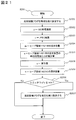
図8は、ステップS205における詳細処理を説明するフローチャートである。以下、図8の各ステップについて説明する。
(図8:ステップS2051)
返却要求契機判定部1417Bは、返却要求契機フラグを無効な値(例えば「0」)に設定する。返却要求契機フラグとは、返却要求を発行すべき契機に達しているか否かを示すフラグである。返却要求契機判定部1417Bは、同フラグの値を、例えばメモリ120内の適当な記憶領域に格納する。
返却要求契機判定部1417Bは、返却要求契機フラグを無効な値(例えば「0」)に設定する。返却要求契機フラグとは、返却要求を発行すべき契機に達しているか否かを示すフラグである。返却要求契機判定部1417Bは、同フラグの値を、例えばメモリ120内の適当な記憶領域に格納する。
(図8:ステップS2052)
返却要求契機判定部1417Bは、貸与情報管理テーブル1411BのGC処理速度フィールド14113Bの値を読み取り、変数yに格納する。
返却要求契機判定部1417Bは、貸与情報管理テーブル1411BのGC処理速度フィールド14113Bの値を読み取り、変数yに格納する。
(図8:ステップS2053)
返却要求契機判定部1417Bは、貸与情報管理テーブル1411Bの貸与先メモリ総量フィールド14112Bの値を読み出し、変数zに格納する。
返却要求契機判定部1417Bは、貸与情報管理テーブル1411Bの貸与先メモリ総量フィールド14112Bの値を読み出し、変数zに格納する。
(図8:ステップS2054)
返却要求契機判定部1417Bは、JavaVM142Bのヒープ領域1421Bの空き容量を取得し、変数mに格納する。
返却要求契機判定部1417Bは、JavaVM142Bのヒープ領域1421Bの空き容量を取得し、変数mに格納する。
(図8:ステップS2055)
返却要求契機判定部1417Bは、ヒープ領域1421Bの空き容量が単位時間当たりに減少する量を算出し、変数nに格納する。具体的には、返却要求契機判定部1417BがステップS2054を前回実行した時に取得したヒープ領域1421Bの空き容量と、今回実行した時に取得したヒープ領域1421Bの空き容量との差分を求め、前回実行時からの経過時間で除算する。
返却要求契機判定部1417Bは、ヒープ領域1421Bの空き容量が単位時間当たりに減少する量を算出し、変数nに格納する。具体的には、返却要求契機判定部1417BがステップS2054を前回実行した時に取得したヒープ領域1421Bの空き容量と、今回実行した時に取得したヒープ領域1421Bの空き容量との差分を求め、前回実行時からの経過時間で除算する。
(図8:ステップS2055:補足)
返却要求契機判定部1417BがステップS2054を最初に実行する時には、前回処理時の空き容量が存在しないので、前回実行時からの差分を求めることができない。この場合は例えば、前回処理時の空き容量の代わりにヒープ領域1421Bのサイズを用い、前回処理時からの経過時間の代わりにJavaVM142Bが起動してから現時点までの経過時間を用いることができる。
返却要求契機判定部1417BがステップS2054を最初に実行する時には、前回処理時の空き容量が存在しないので、前回実行時からの差分を求めることができない。この場合は例えば、前回処理時の空き容量の代わりにヒープ領域1421Bのサイズを用い、前回処理時からの経過時間の代わりにJavaVM142Bが起動してから現時点までの経過時間を用いることができる。
(図8:ステップS2056)
返却要求契機判定部1417Bは、下記式(1)が成立するか否かを判定する。成立する場合はステップS2057へ進み、成立しない場合は本フローチャートを終了する。
z×y≧m/n ・・・(1)
返却要求契機判定部1417Bは、下記式(1)が成立するか否かを判定する。成立する場合はステップS2057へ進み、成立しない場合は本フローチャートを終了する。
z×y≧m/n ・・・(1)
(図8:ステップS2056:補足その1)
式(1)の左辺(「z×y」)は、GCの対象となるメモリ総量(z)に単位メモリ量当たりのGC処理時間(y)を掛けたものである。これは、JavaVM142Aのヒープ領域1421Aに対してGC処理を実施するために要する時間を表す。式(1)の右辺(「m/n」)は、ヒープ領域1421Bの空き容量(m)を単位時間当たりでヒープ領域1421Bの空き容量が減少する量(n)で割ったものである。これは、ヒープ領域1421Bの空き領域がなくなるまでの時間を表す。式(1)が成立する場合、ヒープ領域1421Bの空き領域がなくなるまでの時間より、ヒープ領域1421Aを解放するために要する時間のほうが大きい(あるいは両者が等しい)ことになる。この場合、返却要求をすぐに送信しておかないと、ヒープ領域1421Bに空き領域が枯渇してしまう。そこで、返却要求契機判定部1417Bは、返却要求を送信すべき契機に到達したと判定する。
式(1)の左辺(「z×y」)は、GCの対象となるメモリ総量(z)に単位メモリ量当たりのGC処理時間(y)を掛けたものである。これは、JavaVM142Aのヒープ領域1421Aに対してGC処理を実施するために要する時間を表す。式(1)の右辺(「m/n」)は、ヒープ領域1421Bの空き容量(m)を単位時間当たりでヒープ領域1421Bの空き容量が減少する量(n)で割ったものである。これは、ヒープ領域1421Bの空き領域がなくなるまでの時間を表す。式(1)が成立する場合、ヒープ領域1421Bの空き領域がなくなるまでの時間より、ヒープ領域1421Aを解放するために要する時間のほうが大きい(あるいは両者が等しい)ことになる。この場合、返却要求をすぐに送信しておかないと、ヒープ領域1421Bに空き領域が枯渇してしまう。そこで、返却要求契機判定部1417Bは、返却要求を送信すべき契機に到達したと判定する。
(図8:ステップS2056:補足その2)
返却要求契機判定部1417Bが契機判定のために用いる判定式は、式(1)に限定されるものではない。例えば、メモリ割り当て変更部1423がヒープ領域1421のサイズを変更する処理にかかる時間が無視できないほど大きい場合には、式(1)の左辺にサイズ変更処理にかかる時間を加えてもよい。また式(1)では、ステップS205の実行タイミングによっては、契機判定する時点でヒープ領域1421Bに空き領域がなくなるまでの時間よりもヒープ領域1421Aを解放するために要する時間のほうが大きくなっており、返却が間に合わない恐れがある。そこで、式(1)の左辺に安全係数を表す値を加えてもよい。
返却要求契機判定部1417Bが契機判定のために用いる判定式は、式(1)に限定されるものではない。例えば、メモリ割り当て変更部1423がヒープ領域1421のサイズを変更する処理にかかる時間が無視できないほど大きい場合には、式(1)の左辺にサイズ変更処理にかかる時間を加えてもよい。また式(1)では、ステップS205の実行タイミングによっては、契機判定する時点でヒープ領域1421Bに空き領域がなくなるまでの時間よりもヒープ領域1421Aを解放するために要する時間のほうが大きくなっており、返却が間に合わない恐れがある。そこで、式(1)の左辺に安全係数を表す値を加えてもよい。
(図8:ステップS2057)
返却要求契機判定部1417Bは、返却契機フラグを有効な値(例えば「1」)に設定し、本フローチャートを終了する。
返却要求契機判定部1417Bは、返却契機フラグを有効な値(例えば「1」)に設定し、本フローチャートを終了する。
<実施の形態1:まとめ>
以上のように、本実施形態1に係る計算機100によれば、メモリ管理プログラム141Bは、JavaVM142AがGCを実行するために時間を要する前提の下、JavaVM142Bが使用するメモリ領域が枯渇する前にメモリ管理プログラム141Aへメモリ返却要求を送信する。これにより、JavaVM142Aへ貸与したメモリ容量を返却する処理に時間がかかっても、JavaVM142Bの性能を低下させる可能性を低減することができる。
以上のように、本実施形態1に係る計算機100によれば、メモリ管理プログラム141Bは、JavaVM142AがGCを実行するために時間を要する前提の下、JavaVM142Bが使用するメモリ領域が枯渇する前にメモリ管理プログラム141Aへメモリ返却要求を送信する。これにより、JavaVM142Aへ貸与したメモリ容量を返却する処理に時間がかかっても、JavaVM142Bの性能を低下させる可能性を低減することができる。
なお、本実施形態1において、仮想マシン140Aにはメモリ容量を借りるメモリ管理プログラム141Aを配置し、仮想マシン140Bにはメモリ容量を貸与するメモリ管理プログラム141Bを配置したが、1台の仮想マシン140に双方のメモリ管理プログラム141を配置することもできる。この場合、JavaVM142はメモリ容量を貸すことも借りることもできる。以下の実施形態でも同様である。
また、本実施形態1において、2つのJavaVM142間でメモリ容量を貸し借りする例を説明したが、3つ以上のJavaVM142間でメモリ容量を貸し借りする場合でも、本実施形態1と同様の手法を用いることができる。以下の実施形態でも同様である。
また、本実施形態1において、メモリ管理プログラム141とJavaVM142を一体的に構成することもできる。同様に、メモリ管理プログラム141Aと141Bを一体的に構成し、メモリ容量を借りる機能と貸与する機能を双方とも持たせることもできる。以下の実施形態でも同様である。
また、本実施形態1において、GC処理時間がGC対象のメモリ総量に比例すると想定して、返却要求を発行する契機を判定したが、必ずしもこれに限られるものではない。GC処理時間を推定することができるその他の手法を採用することもできる。以下の実施形態でも同様である。
また、本実施形態1において、メモリ容量を貸し借りするプログラムとしてJavaVM142を採り上げたが、本発明を適用することができるプログラムはJavaVMに限定されるものではない。メモリ容量を使用するその他のプログラムに対しても、本発明を適用することができる。以下の実施形態でも同様である。
また、本実施形態1において、仮想マシン140の配下で各プログラムを動作させ、ハイパーバイザ150を介してメモリ容量を貸し借りする例を説明したが、仮想マシン140の配下で動作するプログラム以外のプログラムについても、本発明で説明した手法を適用することができる。以下の実施形態でも同様である。
<実施の形態2>
本発明の実施形態2では、実施形態1で説明したJavaVM142のGC処理に代えて、またはこれと併用して、ヒープ領域1421内のデータを圧縮することにより、メモリ使用量を削減する手法を説明する。計算機100の全体的な構成は実施形態1と同様であるため、以下では差異点を中心に説明する。
本発明の実施形態2では、実施形態1で説明したJavaVM142のGC処理に代えて、またはこれと併用して、ヒープ領域1421内のデータを圧縮することにより、メモリ使用量を削減する手法を説明する。計算機100の全体的な構成は実施形態1と同様であるため、以下では差異点を中心に説明する。
実施形態1で用いたGC処理によるメモリ容量返却では、ヒープ領域1421Aのほとんどがゴミオブジェクトではないオブジェクト(以下、非ゴミオブジェクト)で占められている場合、十分にメモリ容量を削減できない可能性がある。メモリ容量を十分に削減できない場合、GC処理時間を考慮に入れた契機で返却要求を発行したとしても、JavaVM142Bがメモリ容量を必要とする時までにメモリ容量を返却できず、JavaVM142Bの性能が低下する恐れがある。
これに対し、データ圧縮処理によってメモリ使用量を削減する場合は、非ゴミオブジェクトが占めるメモリ領域も削減対象とすることができ、上記問題が発生しない。
データ圧縮処理は、前述の通り、メモリ中のデータの冗長性を検出することで行われるため、処理対象となるメモリ量が大きいほど処理時間は増加する。本実施形態2では、データ圧縮にかかる処理時間が対象のメモリ量にほぼ比例すると想定し、単位メモリ量当たりのデータ圧縮処理時間と処理対象メモリ量に基づいて、メモリ返却要求を送信する契機を判定する。
図9は、本実施形態2における仮想マシン140Aの詳細構成を示す図である。本実施形態2において、JavaVM142Aは、実施形態1の図2で説明した構成に加え、新たにデータ圧縮処理部1426Aを備える。仮想マシン140Aのその他の構成は、実施形態1と同様である。データ圧縮処理部1426Aの動作は後述する。
図10は、本実施形態2における貸与情報管理テーブル1411Bの構成とデータ例を示す図である。仮想マシン140Bの構成は実施形態1と概ね同様であるが、貸与情報管理テーブル1411Bの構成が異なる。本実施形態2において、貸与情報管理テーブル1411Bは、GC処理速度フィールド14113Bに代えて、圧縮処理速度フィールド14114Bを有する。
圧縮処理速度フィールド14114Bは、JavaVM142Aのデータ圧縮処理部1426Aがヒープ領域1421Aの単位メモリ量(ここではMB)に対してデータ圧縮処理を実施するために要する時間を保持する。
貸与先メモリ総量フィールド14112Bの値と圧縮処理速度フィールド14114Bの値を参照することにより、JavaVM142Aのデータ圧縮処理部1426Aがヒープ領域1421A内のオブジェクトを圧縮してメモリ使用量を削減するために要する時間が分かる。本実施形態2では、この時間を、JavaVM142Aが借りているメモリ容量を返却するのに要する時間であるとみなす。
以上、本実施形態2に係る計算機100の構成を説明した。次に、計算機100の全体的な動作、および各メモリ管理プログラム141間でメモリ容量を貸し借りする動作について説明する。
情報送信部1413Aは、JavaVM142Aが起動する時に、通知受信部1412Bに対して、ヒープ領域1421Aのサイズ、データ圧縮処理部1426Aが単位メモリ量当たりのデータ圧縮処理に要する時間を通知する。これらの値は、あらかじめ運用管理者等が指定しておく。あるいは、情報送信部1413Aが、データ圧縮処理部1426Aにデータ圧縮処理を実行させ、その際に計測した処理時間を通知受信部1412Bに通知することも考えられる。通知を受けた通知受信部1412Bは、その内容を貸与情報管理テーブル1411Bの各フィールドに格納する。
なお、情報送信部1413Aは、JavaVM142Aが起動する時に代えて、またはこれと併用して、JavaVM142Aが稼働している間に、所定時間間隔で上記各情報を通知するようにしてもよい。
本実施形態2では、図5で説明したステップS107において、データ圧縮処理部1426Aがヒープ領域1421A内のデータを圧縮することにより、JavaVM142Aが使用しているメモリ量を削減する。このとき、データの使用頻度に基づいて使用頻度が小さいデータのみを圧縮してもよい。あるいは、圧縮後のデータ量を予測し、データ量削減効果の高いデータのみを圧縮してもよい。データ圧縮処理部1426Aは、任意の圧縮アルゴリズムを使用することができる。
データ圧縮処理部1426Aがヒープ領域1421A内のデータを圧縮した後、メモリ割り当て変更部1423Aは、ヒープ領域1421Aのサイズを減少させる。
図11は、ステップS205における詳細処理を説明するフローチャートである。本実施形態2において、ステップS205の処理は、図8で説明したステップS2052の内容が異なる。その他のステップは図8と同様である。
(図11:ステップS2052)
返却要求契機判定部1417Bは、貸与情報管理テーブル1411Bの圧縮処理速度フィールド14114Bの値を読み取り、変数yに格納する。
返却要求契機判定部1417Bは、貸与情報管理テーブル1411Bの圧縮処理速度フィールド14114Bの値を読み取り、変数yに格納する。
(図11:ステップS2056)
本実施形態2における本ステップは、JavaVM142Aのヒープ領域1421A内のデータを圧縮するのに要する時間と、JavaVM142Bのヒープ領域1421Bが枯渇するまでにかかる見込み時間とを比較していることになる。
本実施形態2における本ステップは、JavaVM142Aのヒープ領域1421A内のデータを圧縮するのに要する時間と、JavaVM142Bのヒープ領域1421Bが枯渇するまでにかかる見込み時間とを比較していることになる。
<実施の形態2:まとめ>
以上のように、本実施形態2に係る計算機100によれば、ヒープ領域1421Aのほとんどが非ゴミオブジェクトで占められている場合でも、JavaVM142Aが使用するメモリ容量を削減することができる。これによって、JavaVM142Bの性能が低下する可能性をより確実に抑えつつ、メモリ容量をJavaVM142Aに貸与することができる。
以上のように、本実施形態2に係る計算機100によれば、ヒープ領域1421Aのほとんどが非ゴミオブジェクトで占められている場合でも、JavaVM142Aが使用するメモリ容量を削減することができる。これによって、JavaVM142Bの性能が低下する可能性をより確実に抑えつつ、メモリ容量をJavaVM142Aに貸与することができる。
なお、本実施形態2では、データ圧縮処理時間が圧縮対象のメモリ総量に比例すると想定して、返却要求を発行する契機を判定したが、必ずしもこれに限られるものではない。データ圧縮処理時間を推定することができるその他の手法を採用することもできる。その他の実施形態でも同様である。
また、本実施形態2において、データ圧縮処理によるメモリ使用量削減と、GC処理によるメモリ使用量削減を、併用することもできる。例えば、まずはGC処理を実施してメモリ使用量を削減し、削減量が不足している場合にはデータ圧縮処理を追加実施する、などの手法が考えられる。
<実施の形態3>
本発明の実施形態3では、実施形態1で説明したJavaVM142のGC処理、および実施形態2で説明したデータ圧縮処理に代えて、またはこれらと併用して、ハイパーバイザ150のページング機能により、メモリ使用量を削減する手法を説明する。計算機100の全体的な構成は実施形態1と同様であるため、以下では差異点を中心に説明する。
本発明の実施形態3では、実施形態1で説明したJavaVM142のGC処理、および実施形態2で説明したデータ圧縮処理に代えて、またはこれらと併用して、ハイパーバイザ150のページング機能により、メモリ使用量を削減する手法を説明する。計算機100の全体的な構成は実施形態1と同様であるため、以下では差異点を中心に説明する。
実施形態1で用いたGC処理によりメモリ使用量を削減する場合、上述したように、十分にメモリ使用量を削減できない可能性がある。また、実施形態2で用いたデータ圧縮処理によってメモリ使用量を削減する場合、ヒープ領域1421内のデータ冗長性が小さいと、十分にメモリ使用量を削減できない可能性がある。
これに対し、ページング機能によるメモリ使用量の削減では、ヒープ領域1421内の非ゴミオブジェクトや冗長性の程度によらずメモリ使用量を削減することができ、上記課題が発生しない。
ページング処理は、前述の通り、メモリ内のデータを他の記憶媒体に複製することで行われるため、ページング対象となるメモリ量にほぼ比例した処理時間が必要となる。本実施形態3では、単位メモリ量当たりのページング処理時間と対象メモリ量に基づいて、メモリ返却要求を発行すべき契機を判定する。
図12は、本実施形態3に係る計算機100の機能ブロック図である。本実施形態3において、計算機100のハイパーバイザ150は、ページング処理部151を備える。その他の構成は実施形態1~2と概ね同様であるため、以下では差異点を中心に説明する。
ページング処理部151は、各仮想マシン140が使用しているメモリ130内のデータを、ページング処理によって他の記憶媒体(例えば記憶部120)に複製する。
図13は、本実施形態3における仮想マシン140Aの詳細構成を示す図である。本実施形態3において、メモリ管理プログラム141Aは、実施形態1~2で説明した構成に加え、ページング要求部1418Aを備える。ページング要求部1418Aは、メモリ管理プログラム141A配下のソフトウェアモジュールなどの形態で実装することができる。
ページング要求部1418Aは、ハイパーバイザ150に対し、ページング処理を実行するように要求する。ページング処理により、仮想マシン140Aが使用しているメモリ使用量を削減することを図る。なお、ヒープ領域1421Aのみをメモリ使用量の削減対象としてもよい。
図14は、本実施形態3における貸与情報管理テーブル1411Bの構成とデータ例を示す図である。仮想マシン140Bの構成は実施形態1と概ね同様であるが、貸与情報管理テーブル1411Bの構成が異なる。本実施形態3において、貸与情報管理テーブル1411Bは、GC処理速度フィールド14113Bに代えて、ページング処理速度フィールド14115Bを有する。貸与している分のメモリ量に対してのみページング処理を実施する場合、貸与先メモリ総量フィールド14112Bは省略することができる。
ページング処理速度フィールド14115Bは、ハイパーバイザ150のページング処理部151がメモリ130の単位メモリ量(ここではMB)に対してページング処理を実施するために要する時間を保持する。
貸与量フィールド14111Bの値とページング処理速度フィールド14115Bの値を参照することにより、ハイパーバイザ150のページング処理部151がヒープ領域1421A内のオブジェクトを圧縮してメモリ使用量を削減するために要する時間が分かる。本実施形態3では、この時間を、JavaVM142Aが借りているメモリ容量を返却するのに要する時間であるとみなす。
以上、本実施形態3に係る計算機100の構成を説明した。次に、計算機100の全体的な動作、および各メモリ管理プログラム141間でメモリ容量を貸し借りする動作について説明する。
情報送信部1413Aは、JavaVM142Aが起動する時に、通知受信部1412Bに対して、ページング処理部151が単位メモリ量当たりのページング処理に要する時間を通知する。これらの値は、あらかじめ運用管理者等が指定しておく。あるいは、情報送信部1413Aが、ページング処理部151にページング処理を実行させ、その際に計測した処理時間を通知受信部1412Bに通知することも考えられる。通知を受けた通知受信部1412Bは、その内容を貸与情報管理テーブル1411Bの対応するフィールドに格納する。
なお、情報送信部1413Aは、JavaVM142Aが起動する時に代えて、またはこれと併用して、JavaVM142Aが稼働している間に、所定時間間隔で上記各情報を通知するようにしてもよい。
本実施形態3では、図5で説明したステップS107において、ページング要求部1418Aからページング処理部151に対してページングを実行するように要求する。ページング処理部151は、仮想マシン140Aに割り当てられているメモリ領域に対してページング処理を実施する。このとき、ヒープ領域1421Aに割り当てられているメモリ領域に対して優先的にページング処理を実施するようにしてもよい。また、必ずしも仮想マシン140Aまたはヒープ領域1421Aに割り当てられているメモリ領域の全てに対してページング処理を実施する必要はなく、一部のメモリ領域のみに対して実施するようにしてもよい。
ページング処理部151がページング処理を実施した後、メモリ割り当て変更部1423Aは、ヒープ領域1421Aのサイズを減少させる。
図15は、ステップS205における詳細処理を説明するフローチャートである。本実施形態3において、ステップS205の処理は、図8で説明したステップS2052~S2053の内容が異なる。その他のステップは図8と同様である。
(図15:ステップS2052)
返却要求契機判定部1417Bは、貸与情報管理テーブル1411Bのページング処理速度フィールド14115Bの値を読み取り、変数yに格納する。
返却要求契機判定部1417Bは、貸与情報管理テーブル1411Bのページング処理速度フィールド14115Bの値を読み取り、変数yに格納する。
(図15:ステップS2053)
返却要求契機判定部1417Bは、貸与情報管理テーブル1411Bの貸与量フィールド14111Bの値を読み取り、変数zに格納する。
返却要求契機判定部1417Bは、貸与情報管理テーブル1411Bの貸与量フィールド14111Bの値を読み取り、変数zに格納する。
(図15:ステップS2056)
本実施形態3における本ステップは、JavaVM142Aが借りているメモリ容量相当分をページング処理するのに要する時間と、JavaVM142Bのヒープ領域1421Bが枯渇するまでにかかる見込み時間とを比較していることになる。
本実施形態3における本ステップは、JavaVM142Aが借りているメモリ容量相当分をページング処理するのに要する時間と、JavaVM142Bのヒープ領域1421Bが枯渇するまでにかかる見込み時間とを比較していることになる。
<実施の形態3:まとめ>
以上のように、本実施形態3に係る計算機100によれば、ヒープ領域1421A内のデータに冗長性があまりない場合でも、JavaVM142Aが使用するメモリ容量を削減することができる。これによって、JavaVM142Bの性能が低下する可能性をより確実に抑えつつ、メモリ容量をJavaVM142Aに貸与することができる。
以上のように、本実施形態3に係る計算機100によれば、ヒープ領域1421A内のデータに冗長性があまりない場合でも、JavaVM142Aが使用するメモリ容量を削減することができる。これによって、JavaVM142Bの性能が低下する可能性をより確実に抑えつつ、メモリ容量をJavaVM142Aに貸与することができる。
なお、本実施形態3において、メモリ管理プログラム141Aがページング要求部1418Aを備えることを説明したが、これに代えてメモリ管理プログラム141Bがページング要求部1418Aを備えるように構成することもできる。この場合、仮想マシン140Aまたはヒープ領域1421Aに割り当てられているメモリ容量に対して、メモリ管理プログラム141Bからページング処理を要求することになる。これにより、メモリ管理プログラム141Aが障害などによってページング処理要求を発行できない場合でも、JavaVM142が借りているメモリ容量を返却することができる。
また、本実施形態3において、メモリ管理プログラム141がページング要求部1418を備えることを説明したが、メモリ管理プログラム141以外のプログラム(例えばJavaVM142)がページング要求部1418を備えるように構成することもできる。
また、本実施形態3において、ページング処理によるメモリ使用量削減に加えて、データ圧縮処理によるメモリ使用量削減、またはGC処理によるメモリ使用量削減のうち少なくともいずれかを併用することもできる。例えば、まずはGC処理を実施してメモリ使用量を削減し、削減量が不足していればデータ圧縮処理を実施し、なお削減量が不足している場合にページングを実施する、などの手法が考えられる。
<実施の形態4>
本発明の実施形態4では、仮想マシン140が3台存在し、メモリ容量をこれら3台の仮想マシン140の間で貸し借りする構成例を説明する。JavaVM142BからJavaVM142Aにメモリ容量を貸与する点は、実施形態1~3と同様である。本実施形態4では、JavaVM142AからJavaVM142Bへメモリ容量を返却する際の処理が、実施形態1~3とは異なる。
本発明の実施形態4では、仮想マシン140が3台存在し、メモリ容量をこれら3台の仮想マシン140の間で貸し借りする構成例を説明する。JavaVM142BからJavaVM142Aにメモリ容量を貸与する点は、実施形態1~3と同様である。本実施形態4では、JavaVM142AからJavaVM142Bへメモリ容量を返却する際の処理が、実施形態1~3とは異なる。
図16は、本実施形態4に係る計算機100の機能ブロック図である。本実施形態4において、計算機100は、3台の仮想マシン140A、140B、140Cを備える。仮想マシン140Cの詳細構成については後述する。その他の構成は実施形態1~3と概ね同様であるため、以下では差異点を中心に説明する。
JavaVM142Aは、JavaVM142Bから借りているメモリ容量を使用中であるなどの理由で返却できないとき、JavaVM142Cからメモリ容量を借りてJavaVM142Bに返却する。これにより、JavaVM142Aは、JavaVM142Bからメモリ返却要求を受けたときでも、使用するメモリ容量を減少させることなく稼動し続けることができる。すなわち、複数の仮想マシン140間で空きメモリ容量を互いに融通し合うことにより、計算機100全体としてのメモリ使用効率を向上させることを図る。
図17は、本実施形態4における仮想マシン140Bの詳細構成を示す図である。本実施形態4において、メモリ管理プログラム141Bは、実施形態1~3で説明した構成に加え、貸与可能量送受信部1419Bを備える。貸与可能量送受信部1419Bは、メモリ管理プログラム141B配下のソフトウェアモジュールなどの形態で実装することができる。
図17では、実施形態1の図3で説明した構成に加えて貸与可能量送受信部1419Bを備えた構成を例示したが、その他の実施形態におけるメモリ管理プログラム141Bの構成に加えて貸与可能量送受信部1419Bを設けることもできる。
貸与可能量送受信部1419Bは、後述する貸与可能量送受信部1419Cから、JavaVM142Cが貸与することができるメモリ容量の値を受信する。この値は、図19で説明する貸与情報管理テーブル141Bに格納される。
図18は、仮想マシン140Cの詳細構成を示す図である。仮想マシン140Cは、仮想マシン140Aに対してメモリ容量を貸与するので、その構成は仮想マシン140Bと概ね同様である。貸与情報管理テーブル1411Cの構成は、実施形態1の図4で説明したものと同様である。
貸与可能量送受信部1419Cは、メモリ管理プログラム141Bの貸与可能量送受信部1419Bに対して、JavaVM142Cが貸与することができるメモリ容量の値を送信する。
図19は、本実施形態4における貸与情報管理テーブル1411Bの構成とデータ例を示す図である。本実施形態4における貸与情報管理テーブル1411Bは、実施形態1~3で説明した構成に加え、新たに貸与可能量フィールド14116Bを有する。
貸与可能量送受信部1419Bは、後述する貸与可能量送受信部1419Cから、JavaVM142Cが貸与することができるメモリ容量の値を受信すると、その値を貸与可能量フィールド14116Bに格納する。
図19では、実施形態1の図4で説明した構成に加えて貸与可能量フィールド14116Bを設けた構成を例示したが、その他の実施形態における貸与情報管理テーブル1411Bの構成に加えて同フィールドを設けることもできる。
以上、本実施形態4に係る計算機100の構成を説明した。次に、計算機100の全体的な動作、および各メモリ管理プログラム141間でメモリ容量を貸し借りする動作について説明する。
情報送信部1413Aは、JavaVM142Aが起動する時、通知受信部1412Bおよび1412Cに対して、ヒープ領域1421Aのサイズ、GC処理部1422Aが単位メモリ量当たりのGC処理に要する時間を通知する。通知を受けた通知受信部1412Bおよび1412Cは、その内容を貸与情報管理テーブル1411Bおよび1411Cの各フィールドに格納する。
メモリ管理プログラム141Cの貸与可能量送受信部1419Cは、JavaVM142Cの稼働中に、所定時間間隔で、メモリ管理プログラム141Bの貸与可能量送受信部1419Bに対して、JavaVM142Cが貸与することができるメモリ量を通知する。JavaVM142Cが貸与できるメモリ量として、例えば、ヒープ領域1421Cの空き容量を通知することが考えられる。通知を受けた貸与可能量送受信部1419Bは、貸与可能量フィールド14116Bに通知された値を格納する。
なお、貸与可能量送受信部1419Cが貸与可能量を所定時間間隔で通知する代わりに、Javaプログラム実行部1425Cの処理によりヒープ領域1421Cの空き容量が変化した契機で通知してもよい。
図20は、本実施形態4におけるステップS107の詳細を示す図である。実施形態1~3では、メモリ管理プログラム141Aはメモリ管理プログラム141Bからメモリ返却要求を受けると、ステップS107でヒープ領域1421Aのサイズを減少させるなどしてJavaVM142Aのメモリ使用量を減少させ、メモリ容量を返却していた。しかし、ステップS107の時点でJavaVM142Aが借りているメモリ容量を使用中である場合、即座にメモリ容量を返却すると、JavaVM142Aの性能を低下させてしまう可能性がある。そこで本実施形態4では、ステップS107において、仮想マシン140Cからメモリ容量を借りた上で返却することとした。以下、図20の各ステップについて説明する。
(図20:ステップS1071)
貸与要求送信部1414Aは、通知受信部1412Cに対し、メモリ容量を貸与するよう要求する。
貸与要求送信部1414Aは、通知受信部1412Cに対し、メモリ容量を貸与するよう要求する。
(図20:ステップS1072~S1073)
通知受信部1412Cは、ステップS1071で貸与要求送信部1414Aが送信した貸与要求を受信する(S1072)。通知受信部1412Cは、ステップS202と同様の手順で、ヒープ領域1421Cのサイズを減少させる(S1073)。
通知受信部1412Cは、ステップS1071で貸与要求送信部1414Aが送信した貸与要求を受信する(S1072)。通知受信部1412Cは、ステップS202と同様の手順で、ヒープ領域1421Cのサイズを減少させる(S1073)。
(図20:ステップS1074)
通知受信部1412Cは、ヒープ領域1421Cのサイズを減少させた後、貸与情報管理テーブル1411Cの貸与量フィールド14111Cの値をヒープ領域1421Cのサイズ減少量分だけ増加させ、ヒープ領域1421Cのサイズ減少量を含んだ応答を、貸与要求送信部1414Aに返す。
通知受信部1412Cは、ヒープ領域1421Cのサイズを減少させた後、貸与情報管理テーブル1411Cの貸与量フィールド14111Cの値をヒープ領域1421Cのサイズ減少量分だけ増加させ、ヒープ領域1421Cのサイズ減少量を含んだ応答を、貸与要求送信部1414Aに返す。
(図20:ステップS1075)
貸与要求送信部1414Aは、ステップS1074で通知受信部1412Cが送信した応答を受信し、本処理シーケンスを終了する。
貸与要求送信部1414Aは、ステップS1074で通知受信部1412Cが送信した応答を受信し、本処理シーケンスを終了する。
図21は、本実施形態4におけるステップS205の詳細処理を説明するフローチャートである。本実施形態4では、実施形態1~3とは異なり、ヒープ領域1421Cの空き容量が十分あるか否かによって、メモリ管理プログラム141Bがメモリ返却要求を発行するタイミングが異なる。以下、図21の各ステップについて説明する。
(図21:ステップS2051~S2055)
これらのステップは、実施形態1の図8と同様である。ただし、ステップS2055の後にステップS2058~S2059が新たに追加されている。
これらのステップは、実施形態1の図8と同様である。ただし、ステップS2055の後にステップS2058~S2059が新たに追加されている。
(図21:ステップS2058)
返却要求契機判定部1417Bは、貸与情報管理テーブル1411Bから貸与量フィールド14111Bの値を読み出し、変数aに格納する。
返却要求契機判定部1417Bは、貸与情報管理テーブル1411Bから貸与量フィールド14111Bの値を読み出し、変数aに格納する。
(図21:ステップS2059)
返却要求契機判定部1417Bは、貸与情報管理テーブル1411Bから貸与可能量フィールド14116Bの値(JavaVM142Cが貸与できるメモリ容量)を読み出し、変数bに格納する。
返却要求契機判定部1417Bは、貸与情報管理テーブル1411Bから貸与可能量フィールド14116Bの値(JavaVM142Cが貸与できるメモリ容量)を読み出し、変数bに格納する。
(図21:ステップS2056)
返却要求契機判定部1417Bは、式(1)および下記式(2)が成立するか否かを判定する。成立する場合はステップS2057へ進み、成立しない場合は本フローチャートを終了する。
b≦a ・・・(2)
返却要求契機判定部1417Bは、式(1)および下記式(2)が成立するか否かを判定する。成立する場合はステップS2057へ進み、成立しない場合は本フローチャートを終了する。
b≦a ・・・(2)
(図21:ステップS2056:補足その1)
式(2)が成立する場合、JavaVM142Cが貸与できるメモリ量(b)よりもJavaVM142Aが借りているメモリ容量(a)の方が大きい。そのため、JavaVM142Cからメモリ容量を貸与するのみでは、JavaVM142Bから借りたメモリ容量を返却することができない。この場合、JavaVM142AがGCを実施する必要がある。
式(2)が成立する場合、JavaVM142Cが貸与できるメモリ量(b)よりもJavaVM142Aが借りているメモリ容量(a)の方が大きい。そのため、JavaVM142Cからメモリ容量を貸与するのみでは、JavaVM142Bから借りたメモリ容量を返却することができない。この場合、JavaVM142AがGCを実施する必要がある。
(図21:ステップS2056:補足その2)
式(1)が成立していても、式(2)が成立しないのであれば、JavaVM142Cからメモリ容量を貸与して、JavaVM142Bに借りている分を返却することができる。同様に式(2)が成立していても、式(1)が成立しないのであれば、ヒープ領域1421Bが枯渇するまでの時間に余裕があることになるので、返却要求を発行しなくともよい。すなわち、式(1)(2)双方が成立する場合に限り、メモリ返却要求を発行すべきタイミングに到達していると判定することになる。
式(1)が成立していても、式(2)が成立しないのであれば、JavaVM142Cからメモリ容量を貸与して、JavaVM142Bに借りている分を返却することができる。同様に式(2)が成立していても、式(1)が成立しないのであれば、ヒープ領域1421Bが枯渇するまでの時間に余裕があることになるので、返却要求を発行しなくともよい。すなわち、式(1)(2)双方が成立する場合に限り、メモリ返却要求を発行すべきタイミングに到達していると判定することになる。
(図21:ステップS2056:補足その3)
図8と同様に、本ステップで返却要求契機判定部1417Bが契機判定のために用いる判定式は、式(1)(2)に限定されるものではない。安全係数などを適宜加味することができる。
図8と同様に、本ステップで返却要求契機判定部1417Bが契機判定のために用いる判定式は、式(1)(2)に限定されるものではない。安全係数などを適宜加味することができる。
<実施の形態4:まとめ>
以上のように、本実施形態4に係る計算機100によれば、JavaVM142Bから借りているメモリ容量を使用中であっても、JavaVM142Cから新たにメモリ容量を借り受けてJavaVM142Bに返却することができる。これにより、計算機100全体としてメモリ使用効率を向上させることができる。
以上のように、本実施形態4に係る計算機100によれば、JavaVM142Bから借りているメモリ容量を使用中であっても、JavaVM142Cから新たにメモリ容量を借り受けてJavaVM142Bに返却することができる。これにより、計算機100全体としてメモリ使用効率を向上させることができる。
なお、本実施形態4において、1台の仮想マシン140に3つのメモリ管理プログラム141A~141Cのうちいずれか2以上を配置することもできる。この場合、JavaVM142は、メモリ容量の貸手、借手、2番目の貸手のうちいずれか2以上の役割を兼ねることができる。
また、本実施形態4において、実施形態1で説明した構成の下で新たに仮想マシン140Cを設けた例を示したが、その他の実施形態で説明した構成の下で仮想マシン140Cを設け、本実施形態4と同様に相互にメモリ容量を貸し借りすることもできる。
<実施の形態5>
以上の実施形態1~4で説明した各プログラムを、半導体メモリ、磁気ディスク、工学ディスクなどの種々の記録媒体にその一部または全部を格納し、計算機にインストールすることにより、各実施形態で説明した計算機100の機能を構成することができる。同様にインターネットなどの通信線を介して同プログラムを計算機に提供し、各実施形態で説明した計算機100の機能を構成することもできる。
以上の実施形態1~4で説明した各プログラムを、半導体メモリ、磁気ディスク、工学ディスクなどの種々の記録媒体にその一部または全部を格納し、計算機にインストールすることにより、各実施形態で説明した計算機100の機能を構成することができる。同様にインターネットなどの通信線を介して同プログラムを計算機に提供し、各実施形態で説明した計算機100の機能を構成することもできる。
100:計算機、110:CPU、120:記憶部、121:Javaプログラム、130:メモリ、140:仮想マシン、141:メモリ管理プログラム、1411:貸与情報管理テーブル、14111:貸与量フィールド、14112:貸与先メモリ総量フィールド、14113:GC処理速度フィールド、14114:圧縮処理速度フィールド、14115:ページング処理速度フィールド、14116:貸与可能量フィールド、1412:通知受信部、1413:情報送信部、1414:貸与要求送信部、1415:返却要求送信部、1416:貸与要求契機判定部、1417:返却要求契機判定部、1418:ページング要求部、1419:貸与可能量送受信部、142:JavaVM、1421:ヒープ領域、1422:GC処理部、1423:メモリ割り当て変更部、1424:参照ルート、1425:Javaプログラム実行部、143:オペレーティングシステム、150:ハイパーバイザ、151:ページング処理部。
Claims (19)
- 演算装置、メモリ、第1プログラムおよび第2プログラムを備えた計算機の前記メモリを管理する方法であって、
前記メモリの記憶容量のうち、前記第1プログラムおよび前記第2プログラムがそれぞれ使用することができる記憶容量を割り当てる割当ステップと、
前記第2プログラムに割り当てられた前記記憶容量の少なくとも一部を、前記第1プログラムが使用することができる記憶容量として割り当て直すステップと、
前記割り当て直した記憶容量を、前記第2プログラムが使用することができる記憶容量として割り当て戻す契機を判定する契機判定ステップと、
前記契機判定ステップで判定された契機に達した時点で、前記割り当て直した記憶容量を前記第2プログラムが使用できる記憶容量として割り当て戻すように前記第1プログラムへ指示するステップと、
前記指示にしたがって、前記割り当て直した記憶容量を、前記第2プログラムが使用することができる記憶容量として割り当て戻す返却ステップと、
を有し、
前記契機判定ステップでは、
前記割り当て直した記憶容量を、前記第2プログラムが使用することができる記憶容量として割り当て戻すために要する時間を推定し、
前記第2プログラムが使用することができる記憶容量が不足して前記第2プログラムの実行性能が低下する前に、前記第2プログラムが使用することができる記憶容量として前記割り当て直した記憶容量が割り当て戻されるように、前記契機を判定する
ことを特徴とするメモリ管理方法。 - 前記契機判定ステップでは、
前記第1プログラムが使用することができる記憶容量の総サイズに基づき、前記割り当て直した記憶容量を、前記第2プログラムが使用することができる記憶容量として割り当て戻すために要する時間を推定し、
その推定結果に基づき、前記第2プログラムが使用することができる記憶容量が不足する前に前記割り当て直した記憶容量が割り当て戻されるように、前記契機を判定する
ことを特徴とする請求項1記載のメモリ管理方法。 - 前記契機判定ステップでは、
前記第2プログラムが使用することができる記憶容量が単位時間当たりに減少する速度に基づき、前記第2プログラムが使用することができる記憶容量が不足するまでにかかる時間を推定する
ことを特徴とする請求項1記載のメモリ管理方法。 - 前記契機判定ステップでは、
前記第1プログラムが使用することができる記憶容量として割り当て直した記憶容量サイズに基づき、前記割り当て直した記憶容量を、前記第2プログラムが使用することができる記憶容量として割り当て戻すために要する時間を推定し、
その推定結果に基づき、前記第2プログラムが使用することができる記憶容量が不足する前に前記割り当て直した記憶容量が割り当て戻されるように、前記契機を判定する
ことを特徴とする請求項1記載のメモリ管理方法。 - 前記返却ステップでは、
前記第1プログラムが使用することができる記憶容量として割り当てられている前記メモリの記憶容量のうち、前記第1プログラムが使用していない不要領域を解放することにより、前記第1プログラムが使用することができる記憶容量を削減し、
その削減した分の記憶容量を、前記第2プログラムが使用することができる記憶容量として割り当て戻す
ことを特徴とする請求項1記載のメモリ管理方法。 - 前記返却ステップでは、
前記第1プログラムが使用することができる記憶容量として割り当てられている前記メモリの記憶容量のうち、冗長なデータを格納している部分を圧縮することにより、前記第1プログラムが使用することができる記憶容量を削減し、
その削減した分の記憶容量を、前記第2プログラムが使用することができる記憶容量として割り当て戻す
ことを特徴とする請求項1記載のメモリ管理方法。 - 前記返却ステップでは、
前記第1プログラムが使用することができる記憶容量として割り当てられている前記メモリの記憶容量の少なくとも一部を、前記メモリ以外の記憶媒体に書き込むことにより、前記第1プログラムが使用することができる記憶容量を削減し、
その削減した分の記憶容量を、前記第2プログラムが使用することができる記憶容量として割り当て戻す
ことを特徴とする請求項1記載のメモリ管理方法。 - 前記計算機は、前記第1プログラムおよび前記第2プログラムとは異なる第3プログラムを備えており、
前記割当ステップでは、
前記メモリの記憶容量のうち、前記第1プログラム、前記第2プログラム、および前記第3プログラムがそれぞれ使用することができる記憶容量を割り当て、
前記返却ステップでは、
前記第3プログラムに割り当てられている前記メモリの記憶容量のうち前記第3プログラムが使用していない記憶容量を、前記第2プログラムが使用することができる記憶容量として割り当て戻す
ことを特徴とする請求項1記載のメモリ管理方法。 - 前記契機判定ステップでは、
前記第3プログラムに割り当てられている前記メモリの記憶容量のうち前記第3プログラムが使用していない記憶容量が、前記第1プログラムが使用することができる記憶容量として一時的に割り当て直した記憶容量よりも小さいとき、
前記第1プログラムが使用することができる記憶容量として一時的に割り当て直した記憶容量を、前記第2プログラムが使用できる記憶容量として割り当て戻す
ことを特徴とする請求項8記載のメモリ管理方法。 - 演算装置、メモリ、第1プログラムおよび第2プログラムを有する計算機に、
前記メモリの記憶容量のうち、前記第1プログラムおよび前記第2プログラムがそれぞれ使用することができる記憶容量を割り当てる割当機能と、
前記第2プログラムに割り当てられた前記記憶容量の少なくとも一部を、前記第1プログラムが使用することができる記憶容量として割り当て直す機能と、
前記割り当て直した記憶容量を、前記第2プログラムが使用することができる記憶容量として割り当て戻すために要する時間を推定し、前記第2プログラムが使用することができる記憶容量が不足して前記第2プログラムの実行性能が低下する前に、前記第2プログラムが使用することができる記憶容量として前記割り当て直した記憶容量が割り当て戻されるように、前記契機を判定する契機判定機能と、
前記契機判定機能で判定された契機に達した時点で、前記割り当て直した記憶容量を前記第2プログラムが使用できる記憶容量として割り当て戻すように前記第1プログラムへ指示する機能と、
前記指示にしたがって、前記割り当て直した記憶容量を、前記第2プログラムが使用することができる記憶容量として割り当て戻す返却機能と、
を実行させるプログラムを格納したことを特徴とする記録媒体。 - 演算装置、メモリ、第1プログラム、および第2プログラムを備えた計算機であって、
前記メモリの記憶容量のうち、前記第1プログラムおよび前記第2プログラムがそれぞれ使用することができる記憶容量を割り当てる割当部と、
前記第2プログラムに割り当てられた前記記憶容量のうち全部または一部を、前記第1プログラムが使用することができる記憶容量として一時的に割り当て直す処理部と、
前記割り当て直した記憶容量を、前記第2プログラムが使用することができる記憶容量として割り当て戻す契機を判定する契機判定部と、
前記契機判定部が判定された契機に達した時点で、前記割り当て直した記憶容量を前記第2プログラムが使用できる記憶容量として割り当て戻すように前記第1プログラムへ指示する処理部と、
前記指示にしたがって、前記割り当て直した記憶容量を、前記第2プログラムが使用することができる記憶容量として割り当て戻す返却部と、
を有し、
前記契機判定部は、
前記割り当て直した記憶容量を、前記第2プログラムが使用することができる記憶容量として割り当て戻すために要する時間を推定し、
前記第2プログラムが使用することができる記憶容量が不足して前記第2プログラムの実行性能が低下する前に、前記第2プログラムが使用することができる記憶容量として前記割り当て直した記憶容量が割り当て戻されるように、前記契機を判定する
ことを特徴とする計算機。 - 前記契機判定部は、
前記第1プログラムが使用することができる記憶容量の総サイズに基づき、前記割り当て直した記憶容量を、前記第2プログラムが使用することができる記憶容量として割り当て戻すために要する時間を推定し、
その推定結果に基づき、前記第2プログラムが使用することができる記憶容量が不足する前に前記割り当て直した記憶容量が割り当て戻されるように、前記契機を判定する
ことを特徴とする請求項11記載の計算機。 - 前記契機判定部は、
前記第2プログラムが使用することができる記憶容量が単位時間当たりに減少する速度に基づき、前記第2プログラムが使用することができる記憶容量が不足するまでにかかる時間を推定する
ことを特徴とする請求項11記載の計算機。 - 前記契機判定部は、
前記第1プログラムが使用することができる記憶容量として割り当て直した記憶容量サイズに基づき、前記割り当て直した記憶容量を、前記第2プログラムが使用することができる記憶容量として割り当て戻すために要する時間を推定し、
その推定結果に基づき、前記第2プログラムが使用することができる記憶容量が不足する前に前記割り当て直した記憶容量が割り当て戻されるように、前記契機を判定する
ことを特徴とする請求項11記載の計算機。 - 前記返却部は、
前記第1プログラムが使用することができる記憶容量として割り当てられている前記メモリの記憶容量のうち、前記第1プログラムが使用していない不要領域を解放することにより、前記第1プログラムが使用することができる記憶容量を削減し、
その削減した分の記憶容量を、前記第2プログラムが使用することができる記憶容量として割り当て戻す
ことを特徴とする請求項11記載の計算機。 - 前記返却部は、
前記第1プログラムが使用することができる記憶容量として割り当てられている前記メモリの記憶容量のうち、冗長なデータを格納している部分を圧縮することにより、前記第1プログラムが使用することができる記憶容量を削減し、
その削減した分の記憶容量を、前記第2プログラムが使用することができる記憶容量として割り当て戻す
ことを特徴とする請求項11記載の計算機。 - 前記返却部は、
前記第1プログラムが使用することができる記憶容量として割り当てられている前記メモリの記憶容量の少なくとも一部を、前記メモリ以外の記憶媒体に書き込むことにより、前記第1プログラムが使用することができる記憶容量を削減し、
その削減した分の記憶容量を、前記第2プログラムが使用することができる記憶容量として割り当て戻す
ことを特徴とする請求項11記載の計算機。 - 前記計算機は、前記第1プログラムおよび前記第2プログラムとは異なる第3プログラムを備えており、
前記割当部は、
前記メモリの記憶容量のうち、前記第1プログラム、前記第2プログラム、および前記第3プログラムがそれぞれ使用することができる記憶容量を割り当て、
前記返却部は、
前記第3プログラムに割り当てられている前記メモリの記憶容量のうち前記第3プログラムが使用していない記憶容量を、前記第2プログラムが使用することができる記憶容量として割り当て戻す
ことを特徴とする請求項11記載の計算機。 - 前記契機判定部は、
前記第3プログラムに割り当てられている前記メモリの記憶容量のうち前記第3プログラムが使用していない記憶容量が、前記第1プログラムが使用することができる記憶容量として一時的に割り当て直した記憶容量よりも小さいとき、
前記第1プログラムが使用することができる記憶容量として一時的に割り当て直した記憶容量を、前記第2プログラムが使用できる記憶容量として割り当て戻す
ことを特徴とする請求項18記載の計算機。
Applications Claiming Priority (2)
| Application Number | Priority Date | Filing Date | Title |
|---|---|---|---|
| JP2010-172674 | 2010-07-30 | ||
| JP2010172674A JP2012033041A (ja) | 2010-07-30 | 2010-07-30 | メモリ管理方法、メモリ管理プログラム、計算機 |
Publications (1)
| Publication Number | Publication Date |
|---|---|
| WO2012014511A1 true WO2012014511A1 (ja) | 2012-02-02 |
Family
ID=45529735
Family Applications (1)
| Application Number | Title | Priority Date | Filing Date |
|---|---|---|---|
| PCT/JP2011/054066 Ceased WO2012014511A1 (ja) | 2010-07-30 | 2011-02-24 | メモリ管理方法、メモリ管理プログラム、計算機 |
Country Status (2)
| Country | Link |
|---|---|
| JP (1) | JP2012033041A (ja) |
| WO (1) | WO2012014511A1 (ja) |
Citations (5)
| Publication number | Priority date | Publication date | Assignee | Title |
|---|---|---|---|---|
| JPH04167152A (ja) * | 1990-10-31 | 1992-06-15 | Nec Corp | 空きメモリ管理方式 |
| JPH0962566A (ja) * | 1995-08-22 | 1997-03-07 | Hitachi Ltd | 情報処理装置およびメモリ管理方法 |
| JPH1097435A (ja) * | 1996-09-20 | 1998-04-14 | Nec Corp | 資源割当てシステム |
| JPH11249955A (ja) * | 1998-02-27 | 1999-09-17 | Ricoh Co Ltd | バッファの動的管理方法およびその方法の各工程をコンピュータに実行させるためのプログラムを記録したコンピュータ読み取り可能な記録媒体 |
| JP2003150394A (ja) * | 2001-11-15 | 2003-05-23 | Hitachi Ltd | メモリ管理方法 |
-
2010
- 2010-07-30 JP JP2010172674A patent/JP2012033041A/ja active Pending
-
2011
- 2011-02-24 WO PCT/JP2011/054066 patent/WO2012014511A1/ja not_active Ceased
Patent Citations (5)
| Publication number | Priority date | Publication date | Assignee | Title |
|---|---|---|---|---|
| JPH04167152A (ja) * | 1990-10-31 | 1992-06-15 | Nec Corp | 空きメモリ管理方式 |
| JPH0962566A (ja) * | 1995-08-22 | 1997-03-07 | Hitachi Ltd | 情報処理装置およびメモリ管理方法 |
| JPH1097435A (ja) * | 1996-09-20 | 1998-04-14 | Nec Corp | 資源割当てシステム |
| JPH11249955A (ja) * | 1998-02-27 | 1999-09-17 | Ricoh Co Ltd | バッファの動的管理方法およびその方法の各工程をコンピュータに実行させるためのプログラムを記録したコンピュータ読み取り可能な記録媒体 |
| JP2003150394A (ja) * | 2001-11-15 | 2003-05-23 | Hitachi Ltd | メモリ管理方法 |
Also Published As
| Publication number | Publication date |
|---|---|
| JP2012033041A (ja) | 2012-02-16 |
Similar Documents
| Publication | Publication Date | Title |
|---|---|---|
| US11016879B2 (en) | Determining costs based on computer memory usage | |
| CN103098014B (zh) | 存储系统 | |
| CN103620548B (zh) | 具有增强的应用元数据的存储器管理器 | |
| US8812639B2 (en) | Job managing device, job managing method and job managing program | |
| US9929931B2 (en) | Efficient provisioning and deployment of virtual machines | |
| CN103069390B (zh) | 在混合计算环境中重新调度工作量的方法和系统 | |
| US10191771B2 (en) | System and method for resource management | |
| US9218206B2 (en) | Memory management model and interface for new applications | |
| CN104519119B (zh) | 用于节流在虚拟化的云计算环境中同时运行并且共享相同资源集合的多个异构迁移会话的方法及系统 | |
| CN110196770B (zh) | 云系统内存数据处理方法、装置、设备及存储介质 | |
| CN111679914B (zh) | 一种内存管理方法、系统、计算机设备及存储介质 | |
| US20100005222A1 (en) | Optimizing virtual memory allocation in a virtual machine based upon a previous usage of the virtual memory blocks | |
| CN103635876B (zh) | 用于未经修改的应用的存储器管理模型和接口 | |
| US20090043873A1 (en) | Methods and Apparatus for Restoring a Node State | |
| JP5585140B2 (ja) | 仮想計算機システムの管理プログラム,管理装置及び管理方法 | |
| US20160057076A1 (en) | Equitable Sharing of System Resources in Workflow Execution | |
| JP2006350780A (ja) | キャッシュ割当制御方法 | |
| JP5616523B2 (ja) | 情報処理システム | |
| JP5218985B2 (ja) | メモリ管理方法計算機システム及びプログラム | |
| Maruf et al. | Memtrade: Marketplace for disaggregated memory clouds | |
| CN107301090A (zh) | 在存储服务器中为应用设置数据处理路径的方法及装置 | |
| Ge et al. | Memory sharing for handling memory overload on physical machines in cloud data centers | |
| US20250086140A1 (en) | Workload-responsive distributed segment cleaning | |
| WO2012014511A1 (ja) | メモリ管理方法、メモリ管理プログラム、計算機 | |
| US20250086143A1 (en) | Workload-responsive segment cleaning |
Legal Events
| Date | Code | Title | Description |
|---|---|---|---|
| 121 | Ep: the epo has been informed by wipo that ep was designated in this application |
Ref document number: 11812107 Country of ref document: EP Kind code of ref document: A1 |
|
| NENP | Non-entry into the national phase |
Ref country code: DE |
|
| 122 | Ep: pct application non-entry in european phase |
Ref document number: 11812107 Country of ref document: EP Kind code of ref document: A1 |