WO2012014363A1 - Device for setting image acquisition conditions, and computer program - Google Patents
Device for setting image acquisition conditions, and computer program Download PDFInfo
- Publication number
- WO2012014363A1 WO2012014363A1 PCT/JP2011/003215 JP2011003215W WO2012014363A1 WO 2012014363 A1 WO2012014363 A1 WO 2012014363A1 JP 2011003215 W JP2011003215 W JP 2011003215W WO 2012014363 A1 WO2012014363 A1 WO 2012014363A1
- Authority
- WO
- WIPO (PCT)
- Prior art keywords
- image
- integrated
- score
- images
- integration
- Prior art date
Links
- 238000004590 computer program Methods 0.000 title claims description 15
- 230000010354 integration Effects 0.000 claims abstract description 33
- 239000002245 particle Substances 0.000 claims abstract description 6
- 238000012545 processing Methods 0.000 abstract description 12
- 238000005259 measurement Methods 0.000 description 59
- 238000000034 method Methods 0.000 description 28
- 230000001186 cumulative effect Effects 0.000 description 11
- 238000005457 optimization Methods 0.000 description 11
- 238000003860 storage Methods 0.000 description 9
- 238000004519 manufacturing process Methods 0.000 description 7
- 239000004065 semiconductor Substances 0.000 description 7
- 238000009825 accumulation Methods 0.000 description 6
- 238000006243 chemical reaction Methods 0.000 description 6
- 238000004364 calculation method Methods 0.000 description 5
- 238000013500 data storage Methods 0.000 description 5
- 238000010586 diagram Methods 0.000 description 5
- 238000010894 electron beam technology Methods 0.000 description 5
- 238000011156 evaluation Methods 0.000 description 5
- 238000012790 confirmation Methods 0.000 description 4
- 238000011109 contamination Methods 0.000 description 4
- 238000001514 detection method Methods 0.000 description 4
- 238000007689 inspection Methods 0.000 description 4
- 238000007726 management method Methods 0.000 description 3
- 230000007423 decrease Effects 0.000 description 2
- 230000007547 defect Effects 0.000 description 2
- 239000006185 dispersion Substances 0.000 description 2
- 238000004088 simulation Methods 0.000 description 2
- XUIMIQQOPSSXEZ-UHFFFAOYSA-N Silicon Chemical compound [Si] XUIMIQQOPSSXEZ-UHFFFAOYSA-N 0.000 description 1
- 230000005540 biological transmission Effects 0.000 description 1
- 230000015572 biosynthetic process Effects 0.000 description 1
- 238000012937 correction Methods 0.000 description 1
- 150000002500 ions Chemical class 0.000 description 1
- 238000012423 maintenance Methods 0.000 description 1
- 238000000691 measurement method Methods 0.000 description 1
- 238000001000 micrograph Methods 0.000 description 1
- 230000003287 optical effect Effects 0.000 description 1
- 238000004626 scanning electron microscopy Methods 0.000 description 1
- 229910052710 silicon Inorganic materials 0.000 description 1
- 239000010703 silicon Substances 0.000 description 1
- 239000000126 substance Substances 0.000 description 1
- 230000001629 suppression Effects 0.000 description 1
Images


Classifications
-
- H—ELECTRICITY
- H01—ELECTRIC ELEMENTS
- H01J—ELECTRIC DISCHARGE TUBES OR DISCHARGE LAMPS
- H01J37/00—Discharge tubes with provision for introducing objects or material to be exposed to the discharge, e.g. for the purpose of examination or processing thereof
- H01J37/02—Details
- H01J37/22—Optical, image processing or photographic arrangements associated with the tube
- H01J37/222—Image processing arrangements associated with the tube
-
- G—PHYSICS
- G06—COMPUTING; CALCULATING OR COUNTING
- G06V—IMAGE OR VIDEO RECOGNITION OR UNDERSTANDING
- G06V10/00—Arrangements for image or video recognition or understanding
- G06V10/70—Arrangements for image or video recognition or understanding using pattern recognition or machine learning
- G06V10/74—Image or video pattern matching; Proximity measures in feature spaces
- G06V10/75—Organisation of the matching processes, e.g. simultaneous or sequential comparisons of image or video features; Coarse-fine approaches, e.g. multi-scale approaches; using context analysis; Selection of dictionaries
- G06V10/751—Comparing pixel values or logical combinations thereof, or feature values having positional relevance, e.g. template matching
-
- H—ELECTRICITY
- H01—ELECTRIC ELEMENTS
- H01J—ELECTRIC DISCHARGE TUBES OR DISCHARGE LAMPS
- H01J37/00—Discharge tubes with provision for introducing objects or material to be exposed to the discharge, e.g. for the purpose of examination or processing thereof
- H01J37/26—Electron or ion microscopes; Electron or ion diffraction tubes
- H01J37/28—Electron or ion microscopes; Electron or ion diffraction tubes with scanning beams
Definitions
- the present invention relates to an image acquisition condition setting apparatus such as a charged particle beam apparatus typified by a scanning electron microscope, and a computer program, and more particularly to an apparatus for setting an apparatus condition of an apparatus for forming an image by signal integration, and a computer program About.
- microscope picks up the processed pattern, displays an image on a display, and performs inspection and measurement (hereinafter sometimes simply referred to as inspection) using an image processing technique.
- Template matching is a technique for identifying a desired target pattern from a search area on a sample.
- the degree of coincidence with a pattern image called a template is determined, and within the search area.
- the position is specified by specifying the position showing the highest degree of coincidence with the template. This calculation is performed by a computer. Specifically, a plurality of gradation values representing the pattern irregularities in the microscope image are compared with a template figure in a certain area, and matching is achieved when the degree of coincidence is high. Automatic measurement is possible by registering the position information and this template in advance.
- a charged particle beam device such as a scanning electron microscope (SEM) is a device that forms an image based on detection of charged particles (electrons, ions) emitted from a sample. It is a device that forms a two-dimensional image by synchronizing the scanning of the display device. In this case, an image having a high S / N ratio is formed by integrating a plurality of image signals (frames). The number of frames is proportional to the number of scans performed by the scanning deflector, and as the number of frames increases, the amount of signal used for image formation also increases. Can be formed.
- SEM scanning electron microscope
- the image acquisition condition setting device includes a pattern matching execution unit that performs pattern matching in the image integration unit, wherein the image integration unit changes the integration number for each of a plurality of integration images acquired in advance, and has different integration numbers.
- a plurality of images are formed, and the pattern matching execution unit executes pattern matching on a plurality of images having different cumulative numbers, obtains a score indicating a degree of coincidence between the template and a position specified by the template, and calculates the score The accumulated number in which the variation is included in a predetermined allowable range, and the integrated image in which each of the plurality of integrated images shows a score of a predetermined value or more.
- a selection unit that selects a number, an accumulated number in which a variation in a dimension value of a pattern specified by the pattern matching is included in a predetermined allowable range, or an accumulated number in which an average value of the dimension values of the pattern is included in a predetermined range
- FIG. 3 is a detailed explanatory diagram of an image acquisition condition setting device.
- the flowchart explaining the process of determining the optimal integrated number of sheets based on the pattern matching score The flowchart explaining the process of determining the optimal integrated number of sheets based on the pattern matching score.
- the graph which shows the relationship between an integrated number of sheets and a length measurement value.
- the figure which shows an example of the table showing the average value of the length measurement value of each integrated number of sheets, and dispersion
- the flowchart explaining the process of setting an optimal acceptance based on the score of pattern matching The flowchart explaining the process of setting an optimal acceptance based on the score of pattern matching.
- reflected light from the sample is detected by a CCD sensor or the like, and in an electron microscope with higher resolution, electrons generated in the sample are detected. This is because processing is performed.
- Image acquisition conditions such as the presence / absence of focus, total number of sheets, and magnification
- Image acquisition conditions such as the presence / absence of focus, total number of sheets, and magnification
- the pattern may not be extracted well and a matching error may occur.
- One solution is to set a larger number of images (frames), which is one of the image acquisition conditions, to make the pattern clearer.
- increasing the number of images more than necessary reduces the throughput. End up.
- the cumulative number of images which is one of the image acquisition conditions that need to be set in advance in the template matching method, is often set more than necessary, which not only reduces throughput, but also affects contamination, shrinkage, and charging. It was received greatly.
- it is desirable to correct the total number of sheets to an appropriate number but for this purpose, confirmation using an apparatus and a sample is necessary. By this confirmation work, the apparatus cannot be used for the original inspection, which leads to a decrease in apparatus operation rate. That is, once the operation on the mass production line is started, it is very difficult to change the image acquisition condition.
- a length-measuring electron microscope (Critical Dimension SEM: CD-SEM) is an apparatus that continuously measures a large number of samples formed through the same manufacturing process. That is, as the measurement process proceeds, image information is accumulated. By storing this image information and using it for the determination for setting the image acquisition condition, it is not necessary to operate the apparatus only for setting the apparatus condition.
- images acquired in the past include changes in pattern size due to process variations, brightness of pattern edges, pattern noise, and the like.
- image acquisition conditions are changed using data of an image group including process variations.
- FIG. 1 is a schematic configuration diagram of a CD-SEM.
- the primary electron beam 104 extracted from the cathode 101 by the voltage V1 applied to the first anode 102 is accelerated by the voltage Vacc applied to the second anode 103 and proceeds to the subsequent lens system.
- the primary electron beam 104 is focused as a minute spot on the sample 107 by the focusing lens 105 and the objective lens 106 controlled by the lens control power supply 114, and is scanned two-dimensionally on the sample 107 by the two-stage deflection coil 108. .
- the scanning signal of the deflection coil 108 is controlled by the deflection control device 109 according to the observation magnification.
- Secondary electrons 110 generated from the sample by the primary electron beam 104 scanned on the sample 107 are detected by a secondary electron detector 111.
- Information on the secondary electrons detected by the secondary electron detector 111 is amplified by the amplifier 112 and displayed on the display of the computer 113.
- a wafer is used as the sample 107.
- a circuit pattern being manufactured is displayed on the screen of the display of the computer 113, and the operator can observe manufacturing defects of the circuit pattern and adhered foreign substances.
- Some CD-SEMs have a function of automatically measuring the width of a circuit pattern using secondary electron information. Processing using such image information and template matching for finding a desired pattern from an image are performed by a calculation unit in the computer 113.
- an image used for template matching and an automatic measurement file for automatically performing measurement are registered in a storage unit in the computer 113, and automatic measurement is performed based on the registered information, and an acquired image is also stored.
- the data is stored in a data storage unit in the computer 113.
- FIG. 2 schematically shows an image acquired by automatic measurement of a CD-SEM.
- (a) in FIG. 2 is standard, (b) has a large pattern size, and (c) has a small pattern size. There is also a thing with large noise like (d).
- an image having a strong pattern edge as shown in (e) and an image having a weak pattern edge as shown in (f) are also included. Differences in images as in (a) to (f) occur due to the influence of process variations or differences in layers even when automatic measurement is executed under the same image acquisition conditions. Differences such as (d) to (f) also appear due to the difference in the number of accumulated images, which is one of the image acquisition conditions. The larger the accumulated number, the more the pattern edge is stronger and the less noise the smaller the accumulated number is. The pattern edge is weak and noisy. The difference between the images as in (a) to (f) affects the score obtained by matching with the template.
- the score is, for example, the degree of coincidence with the template expressed from 0 to 1000. If the degree of coincidence is completely 1000, the score becomes lower as the degree of coincidence decreases.
- acceptance is set as a reference value for determining the presence or absence of a target pattern in order to prevent erroneous detection. Acceptance is a threshold value that is automatically or arbitrarily set by the user. If the score is equal to or higher than the acceptance, the pattern detection is successful, and if the score is lower than that, the matching error is set.
- FIG. 3 is a schematic diagram of the configuration of the CD-SEM and the image acquisition condition optimization function / apparatus.
- the image acquired by the CD-SEM 301 is stored in the data storage unit 302 existing in the computer 113 in FIG. 1, and is transmitted to the image acquisition condition optimization function / device 303 as necessary to optimize the image acquisition condition.
- the function / device 303 performs image acquisition condition optimization.
- the result calculated here is transmitted and re-registered in the storage unit 304 existing in the computer 113 in FIG. 1 as new setting contents of automatic measurement, and automatic measurement of the new setting contents is executed in the CD-SEM 305.
- the image acquired by the CD-SEM 301 is stored in the data storage unit 302 existing in the computer 113 in FIG. 1, and is transmitted to the image acquisition condition optimization function / device 303 as necessary to optimize the image acquisition condition.
- the function / device 303 performs image acquisition condition optimization.
- the result calculated here is transmitted and re-registered in the storage unit 304 existing in the
- the image data stored in the data storage unit 401 is transmitted to the image acquisition condition optimization function / device 409, and the integrated number conversion unit 402 converts it into a plurality of integrated number images.
- the converted image is transmitted to the pattern matching execution unit 403 as needed, and the score is obtained by executing matching between each cumulative number of images and the template.
- the acquired score is temporarily stored in the matching result (score) storage unit 404.
- the length measurement value may change due to contamination or shrinkage change depending on the number of accumulated images. It is necessary to confirm that. Therefore, the length measurement value is obtained by transmitting the image converted by the total number conversion unit 402 to the length measurement execution unit 405 in parallel with the transmission to the pattern matching execution unit 403 and executing the length measurement on each total number of images. And the length measurement result is stored in the length measurement result storage unit 406.
- the image data in the data storage unit 401 has a gradation value of each pixel for each scan.
- N N Frame
- N pieces of data since one scan is repeated N times as shown in FIG. 5 and one image is generated from these data, there are N pieces of data. become.
- N pieces of data By using these N pieces of data, it is possible to generate images of 2 frames, 4 frames, 6 frames and up to N frames as shown in FIG.
- the number of frames to be generated can be set automatically or arbitrarily.
- the pattern matching execution unit 403 in FIG. 4 Details of the pattern matching execution unit 403 in FIG. 4 will be described with reference to FIG.
- the accumulated number conversion unit 402 transmits each accumulated number of images to the pattern matching execution unit 403, matching with the template registered in the automatic length measurement file of the storage unit of the computer 113 in FIG. 1 is executed for each image.
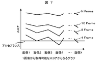
- FIGS. 5 and 6 since a plurality of accumulated number images can be generated from one image, a plurality of scores can be obtained for one image as shown in FIG. 7.
- the score average value and score variation (3 ⁇ ) of each integrated number it is assumed that the calculation result is shown in FIG.
- the filter unit 407 in FIG. 4 determines the optimum integrated number based on the acceptance registered in the automatic measurement file and the arbitrarily set tolerance of the score variation. That is, the filter unit 407 functions as a selection unit that selects a candidate for the integrated number or the final integrated number.
- FIG. 9 illustrates a matching result determination flow.
- the matching result accumulation unit 701 as described above, the average score value and the score variation (3 ⁇ ) of each integrated number are calculated. These pieces of information are transmitted to the filter unit 702, and first, it is confirmed whether the score variation (3 ⁇ ) is within an allowable range. Here, it is assumed that there are a plurality of corresponding conditions when 3 ⁇ is within R. Next, it is confirmed whether or not the score average value is higher than the acceptance set in the automatic length measurement file by a certain amount U or more.
- FIG. 10 shows a determination example in the case of FIG. For example, if the setting acceptance Q of the automatic length measurement file is 300, the tolerance value R of the score variation (3 ⁇ ) is 100, and the fixed amount U is 100, it is determined that 8 frames or more are optimal.
- the filter unit 407 determines the optimum integrated number based on the length measurement management value set in the automatic measurement file and the allowable value of the length measurement variation (3 ⁇ ) set automatically or arbitrarily.
- the measurement result determination flow is shown in FIG.
- the length measurement result accumulation unit 901 the length measurement average value and the length measurement reproducibility (3 ⁇ ) of each integrated number are calculated as described above. These pieces of information are transmitted to the filter unit 902, and first, it is confirmed whether the length measurement reproducibility (3 ⁇ ) is within an allowable range. Here, when 3 ⁇ is within M, an allowable value is assumed to exist. Next, it is confirmed whether the length measurement average value falls within the length measurement management value set in the automatic length measurement file. This is to prevent the length measurement value from changing significantly by changing the cumulative number. If there are a plurality of applicable conditions at this stage, the condition with the smallest cumulative number among them is determined as the optimum condition.
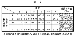
- a determination example in the case of FIG. 12 is shown in FIG.
- the set length measurement management value (N ⁇ P) is within 51.5 nm ⁇ 1 nm and the length measurement reproducibility M is within 3 nm, it is determined that 16 frames or more is optimal. Even when it is determined that 8 Frame is optimal in the determination of the pattern matching result, the determination of the length measurement result is given priority in the case of the length measurement image.
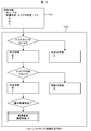
- FIG. 18 is a flowchart illustrating a process for determining an image acquisition condition.
- image data is read from the storage medium in which the images are accumulated (step 1201). Since image data for forming one image includes a plurality of accumulated image data, a plurality of images composed of different accumulated numbers are formed using these image data. (Step 1202). For example, a plurality of images composed of different integrated numbers such as 1 integrated number, 2 integrated numbers, 3 integrated numbers,... N integrated images are formed. If an arithmetic device that forms a plurality of images with different accumulated images in advance and a storage medium that accumulates these different accumulated images are prepared, step 1202 is unnecessary.
- template matching is performed on the integrated image to obtain a score (step 1203).
- a plurality of scores (the degree of coincidence between the template and the part specified by the template) are obtained for one evaluation target image (step 1204).
- a process for obtaining a plurality of scores is performed for different evaluation target images, and a plurality of scores are obtained for the plurality of evaluation target images (step 1205).
- the plurality of scores obtained as described above are compared with preset acceptances (step 1206), and the total number of sheets whose scores exceed the acceptance is selected for all evaluation target images (step 1207). .
- the accumulated number of all scores exceeding the acceptance is a plurality of samples acquired from different samples (different samples acquired under the same manufacturing conditions). It can be said that this is an image acquisition condition in which the success of matching is compensated for in the image. Therefore, if the integrated number is selected from these, at least the success rate of matching can be maintained at a high level.
- the smallest one is selected from the selected integrated number (step 1208).
- the selected integrated number is stored in the recipe as an image acquisition condition (step 1209).
- the acceptance is a value that can be set to an arbitrary value. It can be rewritten when it is determined that the value automatically determined at the time of template registration is high. Therefore, a method is proposed in which it is automatically determined whether or not the automatically determined acceptance is optimal, and when it is determined to be inappropriate, it is automatically or arbitrarily rewritten to an appropriate value. It should be noted that if the acceptance is set too low, a pattern different from the target pattern may be erroneously recognized as the target pattern. In order to prevent erroneous recognition, a minimum acceptance value Qmin that can be set in advance is determined.
- FIG. 16 illustrates an acceptance optimization flow considering these points. If the acceptance is high, even if the score variation (3 ⁇ ) is small and the score average value is high, the score average value confirmation 1103 is processed as a non-applicable condition. Here, it is confirmed whether the score average value of the non-applicable condition is not less than the minimum acceptance Qmin and there is a difference of a certain amount U. When this condition is met, it is possible to adopt a condition in which the cumulative number is further lowered by lowering the acceptance.
- the optimum acceptance value is a value obtained by subtracting a certain amount U from the score average value of non-applicable conditions.
- the optimum condition is selected from the two cases of the case where the acceptance is not optimized and the case where the acceptance is optimized (a plurality of conditions when there are a plurality of corresponding conditions when optimized).
- optimization when optimization is set to automatic, it can be set first whether to select acceptance optimization or not.
- FIG. 8 an example of simulation based on the result of FIG. 8 is shown in FIG. If the acceptance Q registered in the automatic length measurement file is 550, the tolerance R of the score variation (3 ⁇ ) is 100, the constant amount U is 100, and the minimum acceptance Qmin is 300, the number of accumulated sheets is obtained unless the acceptance is optimized. It becomes a judgment that it is necessary to increase more than 16 sheets. When acceptance optimization is enabled, the total number of sheets can be reduced to 8 frames.
Landscapes
- Engineering & Computer Science (AREA)
- Computer Vision & Pattern Recognition (AREA)
- Chemical & Material Sciences (AREA)
- Analytical Chemistry (AREA)
- Theoretical Computer Science (AREA)
- Health & Medical Sciences (AREA)
- Artificial Intelligence (AREA)
- Databases & Information Systems (AREA)
- Evolutionary Computation (AREA)
- General Health & Medical Sciences (AREA)
- Medical Informatics (AREA)
- Software Systems (AREA)
- Computing Systems (AREA)
- Physics & Mathematics (AREA)
- General Physics & Mathematics (AREA)
- Multimedia (AREA)
- Image Analysis (AREA)
- Length-Measuring Devices Using Wave Or Particle Radiation (AREA)
- Testing Or Measuring Of Semiconductors Or The Like (AREA)
Abstract
The present invention relates to a device (303) for setting image acquisition conditions for charged particle beam devices or the like. An image integration unit (402) forms a plurality of images with a number of different integrations (number of integrations 2, 4...N) from one image (number of integrations N) acquired in advance. A pattern matching unit (403) matches the patterns of each of the plurality of images having a number of different integrations with template images registered in advance and then finds a score that shows the degree of matching between images. A selection unit (407) selects a number of integrations such that any variation in the scores is contained within a prescribed allowable range. The selected number of integrations is stored in a recipe of the device. Thus, it is possible to determine the number of integrations in the recipes without having to operate the device, and to set image acquisition conditions so as to allow a minimization of the processing time while maintaining a sufficient S / N ratio.
Description
本発明は、走査電子顕微鏡に代表される荷電粒子線装置等の画像取得条件設定装置、及びコンピュータプログラムに係り、特に、信号積算によって画像を形成する装置の装置条件を設定する装置、及びコンピュータプログラムに関する。
The present invention relates to an image acquisition condition setting apparatus such as a charged particle beam apparatus typified by a scanning electron microscope, and a computer program, and more particularly to an apparatus for setting an apparatus condition of an apparatus for forming an image by signal integration, and a computer program About.
近年、半導体プロセスはますます微細化が進み、顕微鏡を用いた微細パターンの測定や検査が行われている。顕微鏡は、加工されたパターンを撮像してディスプレイに画像を表示し、画像処理技術を用いて検査や測定(以下単に検査と称することもある)を行う。
In recent years, semiconductor processes have been increasingly miniaturized, and micropatterns are being measured and inspected using a microscope. The microscope picks up the processed pattern, displays an image on a display, and performs inspection and measurement (hereinafter sometimes simply referred to as inspection) using an image processing technique.
半導体プロセスの途中で加工された回路パターンを検査する場合、半導体チップ上のすべてのパターンを検査するのは効率的でないので、そのプロセスで不具合が発生しそうな、あるいは過去に発生した箇所に特定して検査することが行われている。
When inspecting circuit patterns processed in the middle of a semiconductor process, it is not efficient to inspect all the patterns on a semiconductor chip. Therefore, it is necessary to specify a place where a defect is likely to occur in the process or has occurred in the past. Inspecting is done.
このとき、その検査すべき特定箇所を分解能の高い顕微鏡で見つけ出すのは、至難の業であるため、特許文献1に開示されているようなテンプレートマッチングとよばれる手法が用いられている。
At this time, finding a specific portion to be inspected with a high-resolution microscope is a difficult task, and a method called template matching as disclosed in Patent Document 1 is used.
テンプレートマッチングは、試料上の探索領域の中から所望の対象パターンを特定する手法であり、探索領域内の各位置にて、テンプレートと呼ばれるパターン画像との一致度判定を行い、探索領域内にてテンプレートと最も高い一致度を示す位置を特定することによって、位置特定を行う。この演算はコンピュータによって行われる。具体的には、顕微鏡画像内のパターンの凹凸を表す複数の階調値と一定領域内のテンプレート図形とを比較し、一致度が高い場合にマッチングがとれたとするものである。位置情報と、このテンプレートを予め登録しておくことで自動測定を可能とする。
Template matching is a technique for identifying a desired target pattern from a search area on a sample. At each position in the search area, the degree of coincidence with a pattern image called a template is determined, and within the search area. The position is specified by specifying the position showing the highest degree of coincidence with the template. This calculation is performed by a computer. Specifically, a plurality of gradation values representing the pattern irregularities in the microscope image are compared with a template figure in a certain area, and matching is achieved when the degree of coincidence is high. Automatic measurement is possible by registering the position information and this template in advance.
走査電子顕微鏡(Scanning Electron Microscope:SEM)等の荷電粒子線装置は、試料から放出される荷電粒子(電子,イオン)の検出に基づいて、画像を形成する装置であり、ビームの走査信号と、表示装置の走査を同期させることによって、二次元像を形成する装置である。この場合、複数の画像信号(フレーム)を積算することによって、S/N比の高い画像を形成する。フレーム数は、走査偏向器による走査回数に比例し、フレーム数が増加すると画像形成に供される信号量も増大するため、被積算対象であるフレーム数が多いとS/N比の高い画像を形成することができる。
A charged particle beam device such as a scanning electron microscope (SEM) is a device that forms an image based on detection of charged particles (electrons, ions) emitted from a sample. It is a device that forms a two-dimensional image by synchronizing the scanning of the display device. In this case, an image having a high S / N ratio is formed by integrating a plurality of image signals (frames). The number of frames is proportional to the number of scans performed by the scanning deflector, and as the number of frames increases, the amount of signal used for image formation also increases. Can be formed.
半導体デバイス等の試料を自動的に測定,検査する走査電子顕微鏡等では、上記フレーム数を含む画像取得条件を予め設定しておく必要があり、テンプレートマッチングに供される画像信号の条件も予め設定しておく必要がある。積算枚数が多いと、S/N比の高い画像を形成できることは、上述の通りであるが、必要以上にビームを走査すると、その分、処理時間が長くなる。また、試料に付着するコンタミネーションやパターンのシュリンク、或いは帯電等が増大する可能性がある。よって、高いS/N比の維持と処理時間等の抑制の両立を図るためには、最適なフレーム数を選択する必要があるが、特許文献1にはパターンマッチングに最適なフレーム数を選択することについての言及がない。
In scanning electron microscopes that automatically measure and inspect semiconductor devices and other specimens, it is necessary to preset image acquisition conditions including the number of frames, and image signal conditions for template matching are also preset. It is necessary to keep it. As described above, it is possible to form an image with a high S / N ratio when the cumulative number is large. However, if the beam is scanned more than necessary, the processing time is increased accordingly. In addition, there is a possibility that contamination that adheres to the sample, pattern shrinkage, charging, or the like increases. Therefore, in order to achieve both the maintenance of a high S / N ratio and the suppression of the processing time, it is necessary to select an optimal number of frames. However, Patent Document 1 selects the optimal number of frames for pattern matching. There is no mention of that.
以下に、高いS/N比の維持と、処理時間等の抑制とを両立する画像取得条件を設定することを目的とする画像取得条件設定装置、及びコンピュータプログラムについて説明する。
Hereinafter, an image acquisition condition setting device and a computer program for setting an image acquisition condition that achieves both maintaining a high S / N ratio and suppressing processing time will be described.
上記目的を達成するための一態様として、以下に、複数の画像信号を積算して画像を形成する画像積算部と、予め登録されたテンプレートを用いて、前記画像積算部によって積算された画像上にてパターンマッチングを実行するパターンマッチング実行部を備えた画像取得条件設定装置であって、前記画像積算部は、予め取得された複数の積算画像毎に、その積算枚数を変えて異なる積算枚数の画像を複数形成し、前記パターンマッチング実行部は、積算枚数の異なる複数の画像上でパターンマッチングを実行し、前記テンプレートと当該テンプレートによって特定された位置との一致度を示すスコアを求め、当該スコアのばらつきが所定の許容範囲に含まれる積算枚数、前記複数の積算画像のいずれもが、所定値以上のスコアを示す積算枚数、前記パターンマッチングによって特定されたパターンの寸法値のばらつきが所定の許容範囲に含まれる積算枚数、或いは当該パターンの寸法値の平均値が所定の範囲に含まれる積算枚数を選択する選択部を備えた画像取得条件設定装置、及び上記処理をコンピュータに実行させるコンピュータプログラムを提案する。
As an aspect for achieving the above object, an image integration unit that integrates a plurality of image signals to form an image and an image integrated by the image integration unit using a pre-registered template are described below. The image acquisition condition setting device includes a pattern matching execution unit that performs pattern matching in the image integration unit, wherein the image integration unit changes the integration number for each of a plurality of integration images acquired in advance, and has different integration numbers. A plurality of images are formed, and the pattern matching execution unit executes pattern matching on a plurality of images having different cumulative numbers, obtains a score indicating a degree of coincidence between the template and a position specified by the template, and calculates the score The accumulated number in which the variation is included in a predetermined allowable range, and the integrated image in which each of the plurality of integrated images shows a score of a predetermined value or more. A selection unit that selects a number, an accumulated number in which a variation in a dimension value of a pattern specified by the pattern matching is included in a predetermined allowable range, or an accumulated number in which an average value of the dimension values of the pattern is included in a predetermined range An image acquisition condition setting device provided and a computer program for causing a computer to execute the above processing are proposed.
上記構成によれば、既に取得された積算画像を用いて適切な画像取得時の積算枚数を選択することができるので、プロセス変動等に応じた適切な画像取得条件を設定することが可能となる。
According to the above configuration, since it is possible to select an appropriate number of accumulated images at the time of image acquisition using already acquired accumulated images, it is possible to set appropriate image acquisition conditions in accordance with process variations and the like. .
顕微鏡には光を照射するものと、電子線を照射するものとがあるが、両者で異なるのは分解能であって、画像処理については同様のものを用いることができる場合がある。
There are microscopes that irradiate light and those that irradiate electron beams, but the difference between them is the resolution, and the same image processing may be used in some cases.
分解能の高い光学式顕微鏡では、試料からの反射光をCCDセンサ等で検知し、さらに分解能の高い電子顕微鏡においては、試料で発生する電子を検知しているが、画像化にはどちらもディジタル信号処理を行うからである。
In an optical microscope with high resolution, reflected light from the sample is detected by a CCD sensor or the like, and in an electron microscope with higher resolution, electrons generated in the sample are detected. This is because processing is performed.
自動的に試料の測定や検査を行う電子顕微鏡等の画像取得条件(フォーカスの有無や積算枚数,倍率など)は、予め登録しておくものだが、半導体製造過程にはプロセス変動が含まれるため、登録した際の条件ではパターンがうまく抽出できずにマッチングエラーとなってしまうことがある。
Image acquisition conditions (such as the presence / absence of focus, total number of sheets, and magnification) of an electron microscope that automatically measures and inspects a sample are registered in advance, but because the semiconductor manufacturing process includes process variations, Under the conditions at the time of registration, the pattern may not be extracted well and a matching error may occur.
その解決策として、画像取得条件の一つである積算枚数(フレーム数)を多めに設定し、パターンを鮮明にすることが挙げられるが、必要以上に積算枚数を多くすることでスループットが低下してしまう。更には、コンタミやシュリンク,帯電の影響が大きくなる可能性もある。
One solution is to set a larger number of images (frames), which is one of the image acquisition conditions, to make the pattern clearer. However, increasing the number of images more than necessary reduces the throughput. End up. Furthermore, there is a possibility that the influence of contamination, shrinkage, and charging will increase.
よって、プロセス変動等に応じて適正な積算枚数を設定することは、マッチングの成功率及び処理時間の短縮化等を実現するためには望ましい対応であると言えるが、適正な設定を行うための明確な指標がなく、誤った設定を行う可能性もあったため、積算枚数の再設定を行うことが困難であった。また、誤った設定を行うと、測定結果等にも影響を与える可能性があり、再設定を行わない一因となっていた。
Therefore, it can be said that setting an appropriate cumulative number according to process fluctuations is desirable for realizing a successful matching rate and a reduction in processing time. Since there is no clear index and there is a possibility of incorrect setting, it is difficult to reset the cumulative number. In addition, if an incorrect setting is made, there is a possibility that the measurement result or the like may be affected, which is one reason for not performing the resetting.
また、テンプレートマッチング方法において予め設定が必要な画像取得条件の一つである積算枚数は、必要以上の枚数が設定されることが多く、スループットの低下だけでなくコンタミやシュリンク,帯電などの影響を大きく受けていた。これを解決するためには、積算枚数を適切な枚数に修正することが望ましいが、そのためには装置と試料を使った確認が必要であった。この確認作業によって、装置を本来の目的である検査に使用できないため、装置稼働率の低下にもつながる。つまり、一度量産ラインでの運用を開始してしまうと、画像取得条件を変更することは非常に困難であった。
In addition, the cumulative number of images, which is one of the image acquisition conditions that need to be set in advance in the template matching method, is often set more than necessary, which not only reduces throughput, but also affects contamination, shrinkage, and charging. It was received greatly. In order to solve this, it is desirable to correct the total number of sheets to an appropriate number, but for this purpose, confirmation using an apparatus and a sample is necessary. By this confirmation work, the apparatus cannot be used for the original inspection, which leads to a decrease in apparatus operation rate. That is, once the operation on the mass production line is started, it is very difficult to change the image acquisition condition.
以下に、装置や試料を用いることなく、装置の設定条件を見出すことを可能とする画像取得条件設定装置、及びコンピュータプログラムについて、更に詳細に説明する。
Hereinafter, an image acquisition condition setting device and a computer program that make it possible to find the setting conditions of the device without using the device or sample will be described in more detail.
装置や試料を用いることなく、装置条件を設定するために、自動測定や自動検査によって得られた画像を用いて、条件設定を行う手法を提案する。測長型電子顕微鏡(Critical Dimension SEM:CD-SEM)は、同じ製造プロセスを経て形成される多数の試料を連続的に測定する装置である。即ち、測定処理が進行するにつれて、画像情報が蓄積される。この画像情報を蓄積しておき、画像取得条件を設定するための判断に用いることによって、装置条件設定のためだけに装置を稼働する必要がなくなる。
In order to set the device conditions without using the device or sample, we propose a method for setting the conditions using images obtained by automatic measurement or automatic inspection. A length-measuring electron microscope (Critical Dimension SEM: CD-SEM) is an apparatus that continuously measures a large number of samples formed through the same manufacturing process. That is, as the measurement process proceeds, image information is accumulated. By storing this image information and using it for the determination for setting the image acquisition condition, it is not necessary to operate the apparatus only for setting the apparatus condition.
また、過去に取得された画像は、プロセス変動によるパターンサイズの変化,パターンエッジの明度,パターンノイズなどを含んでいる。これらの画像群のデータを利用することで、装置と試料を使用せず、画像取得条件を変更した際の変化を確認できる。以下に説明する本実施例装置では、プロセス変動を含んだ画像群のデータを利用して画像取得条件の変更を実施する。
Also, images acquired in the past include changes in pattern size due to process variations, brightness of pattern edges, pattern noise, and the like. By using the data of these image groups, it is possible to confirm changes when the image acquisition conditions are changed without using an apparatus and a sample. In the apparatus according to the present embodiment described below, image acquisition conditions are changed using data of an image group including process variations.
自動測定によって取得したプロセス変動を含んだ画像群を利用することによって、画像取得条件の変更確認のために改めて装置と試料を使用する必要がなくなるため、オフラインでの変更が可能となる。また、短時間での量産展開が可能となるため、これまでマッチングエラーを懸念して修正に踏み込めなかったユーザでも容易に変更することが可能となる。
By using an image group including process fluctuations acquired by automatic measurement, it is not necessary to use the apparatus and the sample again for confirming the change of the image acquisition condition, so that the change can be made offline. Moreover, since mass production can be deployed in a short time, even users who have been concerned about matching errors and have not been able to make corrections can easily make changes.
図1は、CD-SEMの概略構成図である。陰極101から、第1陽極102に印加された電圧V1によって引出された一次電子線104は、第2陽極103に印加される電圧Vaccにより加速されて後段のレンズ系に進行する。この一次電子線104は、レンズ制御電源114で制御された集束レンズ105と対物レンズ106により試料107に微小スポットとして集束され、二段の偏向コイル108によって試料107上を二次元的に走査される。
FIG. 1 is a schematic configuration diagram of a CD-SEM. The primary electron beam 104 extracted from the cathode 101 by the voltage V1 applied to the first anode 102 is accelerated by the voltage Vacc applied to the second anode 103 and proceeds to the subsequent lens system. The primary electron beam 104 is focused as a minute spot on the sample 107 by the focusing lens 105 and the objective lens 106 controlled by the lens control power supply 114, and is scanned two-dimensionally on the sample 107 by the two-stage deflection coil 108. .
偏向コイル108の走査信号は、観察倍率に応じて偏向制御装置109によって制御される。試料107上を走査した一次電子線104により試料から発生した二次電子110は、二次電子検出器111で検出される。二次電子検出器111で検出された二次電子の情報は、増幅器112で増幅され、コンピュータ113のディスプレイに表示される。
The scanning signal of the deflection coil 108 is controlled by the deflection control device 109 according to the observation magnification. Secondary electrons 110 generated from the sample by the primary electron beam 104 scanned on the sample 107 are detected by a secondary electron detector 111. Information on the secondary electrons detected by the secondary electron detector 111 is amplified by the amplifier 112 and displayed on the display of the computer 113.
半導体デバイスの製造プロセスでは、シリコン・ウェーハを加工して半導体デバイスが製造されるので、上記試料107としては、ウェーハが用いられる。コンピュータ113のディスプレイの画面には、製造途中の回路パターンが表示され、オペレータは、回路パターンの製造不良や付着異物を観察できる。また、CD-SEMによっては、二次電子の情報を用いて、回路パターンの幅の測定を自動的に行う機能を備えたものがある。このような画像情報を用いた処理や、画像から所望のパターンを見つけ出すテンプレートマッチングは、コンピュータ113内の演算部で行われる。また、テンプレートマッチングに用いる画像や測定を自動的に行うための自動測定ファイルは、コンピュータ113内の記憶部へ登録されており、これらの登録情報をもとに自動測定を行い、取得した画像もコンピュータ113内のデータ蓄積部に蓄積される。
In the semiconductor device manufacturing process, since a semiconductor device is manufactured by processing a silicon wafer, a wafer is used as the sample 107. A circuit pattern being manufactured is displayed on the screen of the display of the computer 113, and the operator can observe manufacturing defects of the circuit pattern and adhered foreign substances. Some CD-SEMs have a function of automatically measuring the width of a circuit pattern using secondary electron information. Processing using such image information and template matching for finding a desired pattern from an image are performed by a calculation unit in the computer 113. In addition, an image used for template matching and an automatic measurement file for automatically performing measurement are registered in a storage unit in the computer 113, and automatic measurement is performed based on the registered information, and an acquired image is also stored. The data is stored in a data storage unit in the computer 113.
図2は、CD-SEMの自動測定によって取得された画像を模式的に表したものである。図2の(a)を標準としたとき、(b)はパターンサイズが大きく、(c)はパターンサイズが小さい。(d)のようにノイズが大きいものもある。また、(e)のようにパターンエッジが強い画像や(f)のようにパターンエッジが弱い画像も含まれている。(a)から(f)のような画像の差は、同一の画像取得条件で自動測定を実行した場合でもプロセス変動の影響、あるいはレイヤーの違いによって発生する。また(d)から(f)のような差は、画像取得条件の一つである積算枚数の違いによっても表れ、積算枚数が多い程パターンエッジが強くノイズが少ない画像に、積算枚数が少ない程パターンエッジが弱くノイズが多い画像になる。(a)から(f)のような画像の差は、テンプレートとのマッチングによって得られるスコアに影響する。
FIG. 2 schematically shows an image acquired by automatic measurement of a CD-SEM. When (a) in FIG. 2 is standard, (b) has a large pattern size, and (c) has a small pattern size. There is also a thing with large noise like (d). Further, an image having a strong pattern edge as shown in (e) and an image having a weak pattern edge as shown in (f) are also included. Differences in images as in (a) to (f) occur due to the influence of process variations or differences in layers even when automatic measurement is executed under the same image acquisition conditions. Differences such as (d) to (f) also appear due to the difference in the number of accumulated images, which is one of the image acquisition conditions. The larger the accumulated number, the more the pattern edge is stronger and the less noise the smaller the accumulated number is. The pattern edge is weak and noisy. The difference between the images as in (a) to (f) affects the score obtained by matching with the template.
特に、ノイズが多い画像やパターンエッジが弱い画像の場合、パターンの検出がうまくいかず、マッチングエラーになりやすい。ここでスコアについて説明する。スコアとは、例えばテンプレートとの一致度を0から1000で表したものであり、完全に一致していれば1000、一致度が低くなる程にスコアも低くなる。CD-SEMでは、誤検出を防ぐため、目的パターンの有無を判定する基準値として、アクセプタンスを設定している。アクセプタンスとは、自動あるいはユーザによって任意に設定されるしきい値であり、スコアがアクセプタンス以上であればパターン検出成功、それ以下であればマッチングエラーとする値である。
Especially, in the case of an image with a lot of noise or an image with a weak pattern edge, pattern detection is not successful and a matching error is likely to occur. Here, the score will be described. The score is, for example, the degree of coincidence with the template expressed from 0 to 1000. If the degree of coincidence is completely 1000, the score becomes lower as the degree of coincidence decreases. In CD-SEM, acceptance is set as a reference value for determining the presence or absence of a target pattern in order to prevent erroneous detection. Acceptance is a threshold value that is automatically or arbitrarily set by the user. If the score is equal to or higher than the acceptance, the pattern detection is successful, and if the score is lower than that, the matching error is set.
図3は、CD-SEMと画像取得条件最適化機能/装置の構成概略図である。CD-SEM301によって取得された画像は、図1のコンピュータ113内に存在するデータ蓄積部302に蓄積され、必要に応じて画像取得条件最適化機能/装置303へと送信し、画像取得条件最適化機能/装置303にて画像取得条件最適化を行う。ここで算出された結果を、自動測定の新たな設定内容として図1のコンピュータ113内に存在する記憶部304に送信・再登録され、CD-SEM305にて新たな設定内容の自動測定が実行される。
FIG. 3 is a schematic diagram of the configuration of the CD-SEM and the image acquisition condition optimization function / apparatus. The image acquired by the CD-SEM 301 is stored in the data storage unit 302 existing in the computer 113 in FIG. 1, and is transmitted to the image acquisition condition optimization function / device 303 as necessary to optimize the image acquisition condition. The function / device 303 performs image acquisition condition optimization. The result calculated here is transmitted and re-registered in the storage unit 304 existing in the computer 113 in FIG. 1 as new setting contents of automatic measurement, and automatic measurement of the new setting contents is executed in the CD-SEM 305. The
ここで、図3の画像取得条件最適化機能/装置303について詳細を図4にて説明する。まずは、データ蓄積部401に蓄積されていた画像データを画像取得条件最適化機能/装置409へと送信し、積算枚数変換部402にて複数の積算枚数画像へと変換する。変換した画像は、随時パターンマッチング実行部403へと送信し、各積算枚数の画像とテンプレートとのマッチングを実行することでスコアを取得する。
Here, the details of the image acquisition condition optimization function / device 303 of FIG. 3 will be described with reference to FIG. First, the image data stored in the data storage unit 401 is transmitted to the image acquisition condition optimization function / device 409, and the integrated number conversion unit 402 converts it into a plurality of integrated number images. The converted image is transmitted to the pattern matching execution unit 403 as needed, and the score is obtained by executing matching between each cumulative number of images and the template.
取得したスコアは、一時的にマッチング結果(スコア)蓄積部404へ蓄積する。一方、最適化の対象が測長画像であった場合は、積算枚数によってコンタミやシュリンク量の変化によって測長値が変化する恐れがあるため、アクセプタンス以外にも測長値が管理値内に入っていることを確認する必要がある。そこで、積算枚数変換部402にて変換した画像のパターンマッチング実行部403への送信と並行して測長実行部405へ送信し、各積算枚数画像にて測長を実行することで測長値を取得し、測長結果を測長結果蓄積部406へ蓄積する。
The acquired score is temporarily stored in the matching result (score) storage unit 404. On the other hand, when the optimization target is a length measurement image, the length measurement value may change due to contamination or shrinkage change depending on the number of accumulated images. It is necessary to confirm that. Therefore, the length measurement value is obtained by transmitting the image converted by the total number conversion unit 402 to the length measurement execution unit 405 in parallel with the transmission to the pattern matching execution unit 403 and executing the length measurement on each total number of images. And the length measurement result is stored in the length measurement result storage unit 406.
従って、マッチング結果蓄積部404及び測長結果蓄積部406に蓄積された結果を確認することで画像取得条件の一つである積算枚数を変更した場合のシミュレーションをすることが可能になる。これらの蓄積された情報からスコア平均値,スコアばらつき(3σ),測長平均値、及び測長再現性(3σ)を算出し、フィルタ部407にて算出結果から最適な積算枚数を自動判定し最適条件を決定する。
Therefore, by confirming the results accumulated in the matching result accumulation unit 404 and the length measurement result accumulation unit 406, it is possible to perform a simulation when the cumulative number as one of the image acquisition conditions is changed. A score average value, a score variation (3σ), a length measurement average value, and a length measurement reproducibility (3σ) are calculated from the accumulated information, and the optimum integrated number is automatically determined from the calculation result by the filter unit 407. Determine optimal conditions.
ここで、図4の積算枚数変換部402の詳細について図5を用いて説明する。データ蓄積部401の画像データは、1スキャン毎の各画素の階調値を有している。例えば、積算枚数N(N Frame)の画像の場合、図5に示すように1スキャンをN回繰り返し、それらのデータから1枚の画像を生成しているため、N個のデータが存在することになる。このN個のデータを利用することで、図6に示すように2Frame,4Frame,6Frameと、最大N Frameまでの画像を生成できる。生成するFrame数は、自動あるいは任意に設定する
ことができる。 Details of the integratednumber conversion unit 402 in FIG. 4 will be described with reference to FIG. The image data in the data storage unit 401 has a gradation value of each pixel for each scan. For example, in the case of N (N Frame) images, since one scan is repeated N times as shown in FIG. 5 and one image is generated from these data, there are N pieces of data. become. By using these N pieces of data, it is possible to generate images of 2 frames, 4 frames, 6 frames and up to N frames as shown in FIG. The number of frames to be generated can be set automatically or arbitrarily.
ことができる。 Details of the integrated
ここで図4のパターンマッチング実行部403の詳細について図7を用いて説明する。積算枚数変換部402から各積算枚数の画像がパターンマッチング実行部403へ送信されると、図1のコンピュータ113の記憶部の自動測長ファイルに登録されているテンプレートとのマッチングを画像毎に実行する。図5,図6に例示したように、1枚の画像からは、複数個の積算枚数画像を生成可能であるため、図7のように1画像につき複数個のスコアが得られることになる。同様に画像2から画像Xまでのスコアを取得することで、各積算枚数のスコア平均値,スコアばらつき(3σ)を算出できる。ここで、算出結果が図8であるとする。
Details of the pattern matching execution unit 403 in FIG. 4 will be described with reference to FIG. When the accumulated number conversion unit 402 transmits each accumulated number of images to the pattern matching execution unit 403, matching with the template registered in the automatic length measurement file of the storage unit of the computer 113 in FIG. 1 is executed for each image. To do. As illustrated in FIGS. 5 and 6, since a plurality of accumulated number images can be generated from one image, a plurality of scores can be obtained for one image as shown in FIG. 7. Similarly, by acquiring the scores from the image 2 to the image X, it is possible to calculate the score average value and score variation (3σ) of each integrated number. Here, it is assumed that the calculation result is shown in FIG.
一方、図4のフィルタ部407では、自動測定ファイルに登録されていたアクセプタンスと任意で設定したスコアばらつきの許容値をもとに最適な積算枚数を判定する。即ち、フィルタ部407は、積算枚数の候補、或いは最終的な積算枚数を選択する選択部として機能する。
On the other hand, the filter unit 407 in FIG. 4 determines the optimum integrated number based on the acceptance registered in the automatic measurement file and the arbitrarily set tolerance of the score variation. That is, the filter unit 407 functions as a selection unit that selects a candidate for the integrated number or the final integrated number.
ここで、マッチング結果判定フローを図9に例示する。マッチング結果蓄積部701には、前記したように各積算枚数のスコア平均値及びスコアばらつき(3σ)が算出されている。これらの情報をフィルタ部702に送信し、まずはスコアばらつき(3σ)が許容範囲内であるかを確認する。ここで、3σがR以内を許容値としたとき、該当条件が複数個存在したとする。次に、スコア平均値が自動測長ファイルに設定されているアクセプタンスより一定量U以上高いか否かを確認する。
Here, FIG. 9 illustrates a matching result determination flow. In the matching result accumulation unit 701, as described above, the average score value and the score variation (3σ) of each integrated number are calculated. These pieces of information are transmitted to the filter unit 702, and first, it is confirmed whether the score variation (3σ) is within an allowable range. Here, it is assumed that there are a plurality of corresponding conditions when 3σ is within R. Next, it is confirmed whether or not the score average value is higher than the acceptance set in the automatic length measurement file by a certain amount U or more.
アクセプタンスとの差が一定量以上無くては、エラーが頻発する恐れがあるためである。この段階で該当する条件が複数個あった場合、その中でも最も積算枚数の少ない条件が、最適条件として判定される。ここで、図8の場合の判定例を図10に示す。例えば、自動測長ファイルの設定アクセプタンスQが300、スコアばらつき(3σ)の許容値Rが100、一定量Uが100であったとすると、8Frame以上が最適であると判定される。
This is because errors may occur frequently if the difference from the acceptance is not more than a certain amount. If there are a plurality of applicable conditions at this stage, the condition with the smallest cumulative number among them is determined as the optimum condition. Here, FIG. 10 shows a determination example in the case of FIG. For example, if the setting acceptance Q of the automatic length measurement file is 300, the tolerance value R of the score variation (3σ) is 100, and the fixed amount U is 100, it is determined that 8 frames or more are optimal.
次に、図4の測長実行部405の詳細について図11,図12を用いて説明する。積算枚数変換部402から各積算枚数の画像が測長実行部405へ送信されると、自動測長ファイルに登録されている測長方法と同じ条件で測長を画像毎に実行する。前にも説明したように、1枚の画像から複数個の積算枚数画像を生成可能であるため、図11のように1画像につき複数個の測長値が得られる。同様に画像2から画像Xまでの各積算枚数での測長値を取得することで、測長平均値と測長値再現性(3σ)が算出できる。ここで、算出結果が図12であったとする。
Next, details of the length measurement execution unit 405 in FIG. 4 will be described with reference to FIGS. When the accumulated number of images are transmitted from the accumulated number conversion unit 402 to the length measurement execution unit 405, length measurement is performed for each image under the same conditions as the length measurement method registered in the automatic length measurement file. As described above, since a plurality of accumulated number images can be generated from one image, a plurality of length measurement values can be obtained for each image as shown in FIG. Similarly, by obtaining the length measurement values for each integrated number from image 2 to image X, the length measurement average value and the length measurement value reproducibility (3σ) can be calculated. Here, it is assumed that the calculation result is shown in FIG.
一方、フィルタ部407では、自動測定ファイルに設定されている測長管理値と自動あるいは任意で設定した測長ばらつき(3σ)の許容値をもとに最適な積算枚数を判定する。ここで、測長結果判定フローを図13に示す。測長結果蓄積部901には、上述したように各積算枚数の測長平均値及び測長再現性(3σ)が算出されている。これらの情報をフィルタ部902に送信し、まずは測長再現性(3σ)が許容範囲内であるかを確認する。ここで、3σがM以内を許容値としたとき、該当条件が複数個存在したとする。次に、測長平均値が自動測長ファイルに設定されている測長管理値内に該当するかを確認する。積算枚数を変更することで、測長値が著しく変化することを防ぐためである。この段階で該当する条件が複数個あった場合、その中で最も積算枚数が少ない条件が最適条件として判定される。
On the other hand, the filter unit 407 determines the optimum integrated number based on the length measurement management value set in the automatic measurement file and the allowable value of the length measurement variation (3σ) set automatically or arbitrarily. Here, the measurement result determination flow is shown in FIG. In the length measurement result accumulation unit 901, the length measurement average value and the length measurement reproducibility (3σ) of each integrated number are calculated as described above. These pieces of information are transmitted to the filter unit 902, and first, it is confirmed whether the length measurement reproducibility (3σ) is within an allowable range. Here, when 3σ is within M, an allowable value is assumed to exist. Next, it is confirmed whether the length measurement average value falls within the length measurement management value set in the automatic length measurement file. This is to prevent the length measurement value from changing significantly by changing the cumulative number. If there are a plurality of applicable conditions at this stage, the condition with the smallest cumulative number among them is determined as the optimum condition.
ここで、図12の場合の判定例を図14に示す。例えば、設定されていた測長管理値(N±P)が51.5nm±1nm以内、測長再現性Mが3nm以内であったとすると、16Frame以上が最適であると判断される。パターンマッチング結果の判定で8Frameが最適であると判定された場合でも、測長画像の場合は測長結果の判定を優先する。
Here, a determination example in the case of FIG. 12 is shown in FIG. For example, if the set length measurement management value (N ± P) is within 51.5 nm ± 1 nm and the length measurement reproducibility M is within 3 nm, it is determined that 16 frames or more is optimal. Even when it is determined that 8 Frame is optimal in the determination of the pattern matching result, the determination of the length measurement result is given priority in the case of the length measurement image.
図18は、画像取得条件の決定プロセスを説明するフローチャートである。まず、処理開始後、画像が蓄積された記憶媒体から、画像データを読み出す(ステップ1201)。1枚の画像を形成するための画像データの中には、複数の被積算画像データが含まれているため、これらの画像データを用いて、異なる積算枚数から構成される複数の画像を形成する(ステップ1202)。例えば積算枚数1枚,積算枚数2枚,積算枚数3枚…積算枚数N枚のように異なる積算枚数から構成される複数の画像を形成する。予め異なる積算枚数の複数の画像を形成する演算装置と、これらの異なる積算画像を蓄積するような記憶媒体が用意されているのであれば、ステップ1202は不要となる。
FIG. 18 is a flowchart illustrating a process for determining an image acquisition condition. First, after the processing is started, image data is read from the storage medium in which the images are accumulated (step 1201). Since image data for forming one image includes a plurality of accumulated image data, a plurality of images composed of different accumulated numbers are formed using these image data. (Step 1202). For example, a plurality of images composed of different integrated numbers such as 1 integrated number, 2 integrated numbers, 3 integrated numbers,... N integrated images are formed. If an arithmetic device that forms a plurality of images with different accumulated images in advance and a storage medium that accumulates these different accumulated images are prepared, step 1202 is unnecessary.
次に積算画像に対し、テンプレートマッチングを実行し、スコアを求める(ステップ1203)。テンプレートマッチング処理を、異なる積算枚数の画像毎に実行することによって、1の評価対象画像について、複数のスコア(テンプレートとテンプレートによって特定される個所との一致度)を求める(ステップ1204)。次に複数のスコアを求める処理を、異なる評価対象画像に対しても実施し、複数の評価対象画像について、複数のスコアを求める(ステップ1205)。以上のようにして得られた複数のスコアと、予め設定されているアクセプタンスを比較(ステップ1206)し、全ての評価対象画像について、スコアがアクセプタンスを上回っている積算枚数を選択する(ステップ1207)。アクセプタンスは、マッチングの成功,非成功を判断する閾値であるため、全てのスコアがアクセプタンスを上回っている積算枚数とは、異なる試料(同じ製造条件で取得された異なる試料)から取得された複数の画像にて、マッチングの成功が補償された画像取得条件であると言える。よって、この中から積算枚数を選択するようにすれば、少なくとも、マッチングの成功率を高い状態に維持することができる。
Next, template matching is performed on the integrated image to obtain a score (step 1203). By executing the template matching process for each different number of integrated images, a plurality of scores (the degree of coincidence between the template and the part specified by the template) are obtained for one evaluation target image (step 1204). Next, a process for obtaining a plurality of scores is performed for different evaluation target images, and a plurality of scores are obtained for the plurality of evaluation target images (step 1205). The plurality of scores obtained as described above are compared with preset acceptances (step 1206), and the total number of sheets whose scores exceed the acceptance is selected for all evaluation target images (step 1207). . Since acceptance is a threshold value for determining success or failure of matching, the accumulated number of all scores exceeding the acceptance is a plurality of samples acquired from different samples (different samples acquired under the same manufacturing conditions). It can be said that this is an image acquisition condition in which the success of matching is compensated for in the image. Therefore, if the integrated number is selected from these, at least the success rate of matching can be maintained at a high level.
次に、選択された積算枚数の中から最小のものを選択する(ステップ1208)。マッチングの高い成功率が補償された積算枚数から最小のものを選択することによって、マッチングの成功率を高い状態に維持しつつ、試料に対するビーム照射を最小限にすることができる。
Next, the smallest one is selected from the selected integrated number (step 1208). By selecting the smallest number from the accumulated number compensated for the high matching success rate, the beam irradiation on the sample can be minimized while maintaining the high matching success rate.
最後に、選択された積算枚数を画像取得条件としてレシピに記憶する(ステップ1209)。以上のような工程を経ることによって、適正な画像取得条件を装置の稼働率を下げることなく設定することが可能となる。
Finally, the selected integrated number is stored in the recipe as an image acquisition condition (step 1209). By going through the above-described steps, it is possible to set appropriate image acquisition conditions without reducing the operating rate of the apparatus.
CD-SEMの自動測長ファイルでは、テンプレートマッチングで成功するか否かの判定はアクセプタンスによって決定すると前にも述べたが、アクセプタンスはマッチングの成功率を優先して設定すると、必要以上に高くなる場合がある。アクセプタンスの自動決定について詳細を、図15を用いて説明する。まずはテンプレートとして登録する画像1001を取得する。次に、取得した画像内で画像認識の目標となる目標パターン1002を登録する。目標パターンの登録と同時に、取得した画像内で目標パターンによる画像認識1003を実施し、最もスコアの高い第一候補スコアS1と2番目にスコアの高い第二候補スコアS2を抽出し、S1とS2からアクセプタンスを算出する。アクセプタンスはS1とS2の平均値である。S1が800、S2が300であった場合、アクセプタンスは550となる。
As described above, in the CD-SEM automatic length measurement file, whether or not the template matching is successful is determined by the acceptance. However, if the success rate of the matching is set with priority, the acceptance becomes higher than necessary. There is a case. Details of the automatic determination of the acceptance will be described with reference to FIG. First, an image 1001 to be registered as a template is acquired. Next, a target pattern 1002 which is a target for image recognition in the acquired image is registered. Simultaneously with the registration of the target pattern, image recognition 1003 by the target pattern is performed in the acquired image, and the first candidate score S1 having the highest score and the second candidate score S2 having the second highest score are extracted, and S1 and S2 The acceptance is calculated from The acceptance is an average value of S1 and S2. When S1 is 800 and S2 is 300, the acceptance is 550.
ここで、アクセプタンスは任意の値に設定することも可能な値である。テンプレート登録時に自動で決定された値が高いと判断した場合に書き換えることができる。そこで、自動決定されたアクセプタンスが最適か否かを自動で判定し、不適切であると判定された場合に適切な値に自動もしくは任意で書き換える方法を提案する。注意しなくてはならないのは、アクセプタンスを低く設定しすぎると目標パターンとは異なるパターンを目標パターンであると誤認識する可能性が出てくることである。誤認識を防ぐために、予め設定可能なアクセプタンスの最低値Qminを定めておく。
Here, the acceptance is a value that can be set to an arbitrary value. It can be rewritten when it is determined that the value automatically determined at the time of template registration is high. Therefore, a method is proposed in which it is automatically determined whether or not the automatically determined acceptance is optimal, and when it is determined to be inappropriate, it is automatically or arbitrarily rewritten to an appropriate value. It should be noted that if the acceptance is set too low, a pattern different from the target pattern may be erroneously recognized as the target pattern. In order to prevent erroneous recognition, a minimum acceptance value Qmin that can be set in advance is determined.
また、アクセプタンスとスコア平均値とで差がなくてもエラーが頻発してしまうので、一定以上の差を持たせるようにアクセプタンスを設定する必要がある。これらを留意したアクセプタンスの最適化フローを図16に例示する。アクセプタンスが高いと、スコアばらつき(3σ)が小さくスコア平均値が高くてもスコア平均値の確認1103で非該当条件として処理されてしまう。ここで、非該当となった条件のスコア平均値が最低アクセプタンスQmin以上かつ一定量Uの差があるかを確認する。この条件に該当した場合、アクセプタンスを下げることで積算枚数をより下げた条件を採用することが可能になる。
Also, errors occur frequently even if there is no difference between the acceptance and the average score, so it is necessary to set the acceptance so as to have a certain difference. FIG. 16 illustrates an acceptance optimization flow considering these points. If the acceptance is high, even if the score variation (3σ) is small and the score average value is high, the score average value confirmation 1103 is processed as a non-applicable condition. Here, it is confirmed whether the score average value of the non-applicable condition is not less than the minimum acceptance Qmin and there is a difference of a certain amount U. When this condition is met, it is possible to adopt a condition in which the cumulative number is further lowered by lowering the acceptance.
最適なアクセプタンス値は、非該当条件のスコア平均値から一定量Uを引いた値とする。しかしながら、アクセプタンスを下げた条件を採用するか否かは、自動あるいは任意で選択できるようにする。つまり、最適条件として、アクセプタンスを最適化しなかった場合と、最適化した場合との2通り(最適化した際に複数該当条件があった場合は複数条件)から選択する。また、最適化を自動に設定していた場合、アクセプタンス最適化したものかしてないどちらを選ぶかを先に設定することができる。
∙ The optimum acceptance value is a value obtained by subtracting a certain amount U from the score average value of non-applicable conditions. However, it is possible to select automatically or arbitrarily whether or not to adopt a condition with reduced acceptance. That is, the optimum condition is selected from the two cases of the case where the acceptance is not optimized and the case where the acceptance is optimized (a plurality of conditions when there are a plurality of corresponding conditions when optimized). In addition, when optimization is set to automatic, it can be set first whether to select acceptance optimization or not.
ここで、図8の結果をもとに、シミュレーションした例を図17に示す。自動測長ファイルに登録されていたアクセプタンスQが550、スコアばらつき(3σ)の許容値Rが100、一定量Uが100、最低アクセプタンスQminが300であった場合、アクセプタンスを最適化しない限り積算枚数を16枚より多くする必要があるという判定になってしまう。アクセプタンスの最適化を有効にした場合は、積算枚数を8Frameまで下げることが可能になる。
Here, an example of simulation based on the result of FIG. 8 is shown in FIG. If the acceptance Q registered in the automatic length measurement file is 550, the tolerance R of the score variation (3σ) is 100, the constant amount U is 100, and the minimum acceptance Qmin is 300, the number of accumulated sheets is obtained unless the acceptance is optimized. It becomes a judgment that it is necessary to increase more than 16 sheets. When acceptance optimization is enabled, the total number of sheets can be reduced to 8 frames.
101 陰極
102 第1陽極
103 第2陽極
104 一次電子線
105 集束レンズ
106 対物レンズ
107 試料
108 偏向コイル
109 偏向制御装置
110 二次電子
111 二次電子検出器
112 増幅器
113 コンピュータ
114 レンズ制御電源
301,305 CD-SEM
302,401 データ蓄積部
303,409 画像取得条件最適化機能/装置
304 記憶部
402 精算枚数変換部
403 パターンマッチング実行部
404 マッチング結果(スコア)蓄積部
405 測長実行部
406,901,903 測長結果蓄積部
407,702,704,902,904,1102,1105 フィルタ部
701,703,1101,1104 マッチング結果蓄積部
1001 テンプレート登録画像
1002 目標パターン登録
1103 スコア平均値の確認 101Cathode 102 First Anode 103 Second Anode 104 Primary Electron Beam 105 Focusing Lens 106 Objective Lens 107 Sample 108 Deflection Coil 109 Deflection Control Device 110 Secondary Electron 111 Secondary Electron Detector 112 Amplifier 113 Computer 114 Lens Control Power Supply 301, 305 CD-SEM
302, 401 Data storage unit 303, 409 Image acquisition condition optimization function / device 304 Storage unit 402 Settling number conversion unit 403 Pattern matching execution unit 404 Matching result (score) storage unit 405 Length measurement execution unit 406, 901, 903 Length measurement Result accumulation unit 407, 702, 704, 902, 904, 1102, 1105 Filter unit 701, 703, 1101, 1104 Matching result accumulation unit 1001 Template registration image 1002 Target pattern registration 1103 Confirmation of average score value
102 第1陽極
103 第2陽極
104 一次電子線
105 集束レンズ
106 対物レンズ
107 試料
108 偏向コイル
109 偏向制御装置
110 二次電子
111 二次電子検出器
112 増幅器
113 コンピュータ
114 レンズ制御電源
301,305 CD-SEM
302,401 データ蓄積部
303,409 画像取得条件最適化機能/装置
304 記憶部
402 精算枚数変換部
403 パターンマッチング実行部
404 マッチング結果(スコア)蓄積部
405 測長実行部
406,901,903 測長結果蓄積部
407,702,704,902,904,1102,1105 フィルタ部
701,703,1101,1104 マッチング結果蓄積部
1001 テンプレート登録画像
1002 目標パターン登録
1103 スコア平均値の確認 101
302, 401
Claims (10)
- 複数の画像信号を積算して画像を形成する画像積算部と、予め登録されたテンプレートを用いて、前記画像積算部によって積算された画像上にてパターンマッチングを実行するパターンマッチング実行部を備えた画像取得条件設定装置であって、
前記画像積算部は、予め取得された複数の積算画像毎に、その積算枚数を変えて異なる積算枚数の画像を複数形成し、
前記パターンマッチング実行部は、積算枚数の異なる複数の画像上でパターンマッチングを実行し、前記テンプレートと当該テンプレートによって特定された位置との一致度を示すスコアを求め、
当該スコアのばらつきが所定の許容範囲に含まれる積算枚数、前記複数の積算画像のいずれもが、所定値以上のスコアを示す積算枚数、前記パターンマッチングによって特定されたパターンの寸法値のばらつきが所定の許容範囲に含まれる積算枚数、或いは当該パターンの寸法値の平均値が所定の範囲に含まれる積算枚数を選択する選択部を備えた画像取得条件設定装置。 An image integration unit that integrates a plurality of image signals to form an image, and a pattern matching execution unit that executes pattern matching on the image integrated by the image integration unit using a template registered in advance. An image acquisition condition setting device,
The image integration unit, for each of a plurality of integration images acquired in advance, to form a plurality of images of different integration number by changing the integration number,
The pattern matching execution unit performs pattern matching on a plurality of images having different accumulated numbers, and obtains a score indicating a degree of coincidence between the template and a position specified by the template,
The total number of sheets in which the variation of the score is included in a predetermined allowable range, the total number of sheets in which each of the plurality of integrated images shows a score of a predetermined value or more, and the variation in the dimension value of the pattern specified by the pattern matching is predetermined. An image acquisition condition setting device comprising a selection unit that selects an accumulated number included in the allowable range or an average number of dimension values of the pattern included in a predetermined range. - 請求項1において、
前記選択部は、選択した積算枚数が複数存在する場合に、当該選択された積算枚数の内、最も少ない積算枚数を、前記画像積算部の積算枚数として選択することを特徴とする画像取得条件設定装置。 In claim 1,
The selection unit is configured to select an image acquisition condition setting in which, when there are a plurality of selected integration sheets, the smallest integration number among the selected integration sheets is selected as the integration number of the image integration unit. apparatus. - 請求項1において、
前記選択部は、前記スコアのばらつきが所定の許容範囲に含まれる積算枚数が、複数存在する場合に、前記選択された積算枚数の内、所定の許容値から一定量以上高いスコアを示す積算枚数を選択することを特徴とする画像取得条件設定装置。 In claim 1,
The selection unit, when there are a plurality of integrated sheets in which the variation in the score is included in a predetermined allowable range, of the selected integrated sheets, indicates an integrated sheet showing a score higher than a predetermined allowable value by a certain amount or more. An image acquisition condition setting device characterized by selecting. - 請求項1において、
前記積算画像は、複数の画像データが積算された画像であることを特徴とする画像取得条件設定装置。 In claim 1,
The image acquisition condition setting device, wherein the integrated image is an image obtained by integrating a plurality of image data. - 請求項1において、
前記パターンマッチング実行部は、パターンマッチングによる第1候補のスコアと第2候補のスコアとの間のスコアを、テンプレートマッチング時のマッチング成否の閾値とすることを特徴とする画像取得条件設定装置。 In claim 1,
The said pattern matching execution part makes the score between the score of the 1st candidate by a pattern matching and the score of a 2nd candidate the threshold value of the matching success at the time of template matching, The image acquisition condition setting apparatus characterized by the above-mentioned. - 請求項1において、
前記選択部は、前記選択された積算枚数を荷電粒子線装置の装置条件として、設定することを特徴とする画像取得条件設定装置。 In claim 1,
The image acquisition condition setting apparatus, wherein the selection unit sets the selected integrated number as an apparatus condition of the charged particle beam apparatus. - コンピュータに、荷電粒子線装置によって得られた画像信号を積算させて積算画像を形成させ、予め登録されたテンプレートを用いて、前記積算画像上にてパターンマッチングを実行させるコンピュータプログラムであって、
当該コンピュータプログラムは、前記コンピュータに、予め取得された複数の積算画像毎に、その積算枚数を変えて異なる積算枚数の画像を複数形成させ、当該積算枚数の異なる複数の画像上でパターンマッチングを実行させ、前記テンプレートと当該テンプレートによって特定された位置との一致度を示すスコアを求めさせ、当該スコアのばらつきが所定の許容範囲に含まれる積算枚数、前記複数の積算画像のいずれもが、所定値以上のスコアを示す積算枚数、前記パターンマッチングによって特定されたパターンの寸法値のばらつきが所定の許容範囲に含まれる積算枚数、或いは当該パターンの寸法値の平均値が所定の範囲に含まれる積算枚数を選択させることを特徴とするコンピュータプログラム。 A computer program that causes a computer to integrate image signals obtained by a charged particle beam device to form an integrated image, and to perform pattern matching on the integrated image using a template registered in advance,
The computer program causes the computer to form a plurality of images with different integration numbers by changing the integration number for each of a plurality of integration images acquired in advance, and execute pattern matching on the plurality of images with different integration numbers And calculating a score indicating the degree of coincidence between the template and the position specified by the template, and the total number of images in which the variation in the score is included in a predetermined allowable range, and any of the plurality of integrated images is a predetermined value. The accumulated number showing the above score, the accumulated number in which the variation of the dimension value of the pattern specified by the pattern matching is included in the predetermined allowable range, or the integrated number in which the average value of the dimension value of the pattern is included in the predetermined range A computer program characterized by causing selection. - 請求項7において、
前記コンピュータプログラムは、前記コンピュータに、選択した積算枚数が複数存在する場合に、当該選択された積算枚数の内、最も少ない積算枚数を、前記画像積算部の積算枚数として選択させることを特徴とするコンピュータプログラム。 In claim 7,
The computer program causes the computer to select the smallest integrated number of the selected integrated sheets as the integrated number of the image integrating unit when there are a plurality of selected integrated sheets. Computer program. - 請求項7において、
前記コンピュータプログラムは、前記コンピュータに、前記スコアのばらつきが所定の許容範囲に含まれる積算枚数が、複数存在する場合に、前記選択された積算枚数の内、所定の許容値から一定量以上高いスコアを示す積算枚数を選択させることを特徴とするコンピュータプログラム。 In claim 7,
When the computer program includes a plurality of integrated sheets in which the variation in the score falls within a predetermined allowable range, the computer program has a score higher than a predetermined allowable value by a predetermined amount or more from the selected integrated number. A computer program for selecting an accumulated number indicating - 請求項7において、
前記積算画像は、複数の画像データが積算された画像であることを特徴とするコンピュータプログラム。 In claim 7,
The computer program according to claim 1, wherein the integrated image is an image obtained by integrating a plurality of image data.
Priority Applications (1)
| Application Number | Priority Date | Filing Date | Title |
|---|---|---|---|
| US13/812,847 US9230182B2 (en) | 2010-07-28 | 2011-06-08 | Device for setting image acquisition conditions, and computer program |
Applications Claiming Priority (2)
| Application Number | Priority Date | Filing Date | Title |
|---|---|---|---|
| JP2010-168778 | 2010-07-28 | ||
| JP2010168778A JP5174863B2 (en) | 2010-07-28 | 2010-07-28 | Image acquisition condition setting device and computer program |
Publications (1)
| Publication Number | Publication Date |
|---|---|
| WO2012014363A1 true WO2012014363A1 (en) | 2012-02-02 |
Family
ID=45529602
Family Applications (1)
| Application Number | Title | Priority Date | Filing Date |
|---|---|---|---|
| PCT/JP2011/003215 WO2012014363A1 (en) | 2010-07-28 | 2011-06-08 | Device for setting image acquisition conditions, and computer program |
Country Status (3)
| Country | Link |
|---|---|
| US (1) | US9230182B2 (en) |
| JP (1) | JP5174863B2 (en) |
| WO (1) | WO2012014363A1 (en) |
Cited By (1)
| Publication number | Priority date | Publication date | Assignee | Title |
|---|---|---|---|---|
| US20150279614A1 (en) * | 2012-10-16 | 2015-10-01 | Hitachi High-Technologies Corporation | Charged-Particle Radiation Apparatus |
Families Citing this family (5)
| Publication number | Priority date | Publication date | Assignee | Title |
|---|---|---|---|---|
| KR101411119B1 (en) * | 2010-09-25 | 2014-06-25 | 가부시키가이샤 히다치 하이테크놀로지즈 | Charged particle beam microscope |
| KR101904160B1 (en) | 2012-02-08 | 2018-10-05 | 에스케이이노베이션 주식회사 | micro-porous hybrid polyolefin film having excellent thermal property and stability and manufacturing method thereof |
| JP6173659B2 (en) * | 2012-03-06 | 2017-08-02 | 株式会社ホロン | Electron beam image acquisition apparatus and electron beam image acquisition method |
| JP6683583B2 (en) * | 2016-09-30 | 2020-04-22 | 株式会社ホロン | Electron beam image acquisition device and electron beam image acquisition method |
| JP6500055B2 (en) * | 2017-05-25 | 2019-04-10 | 株式会社ホロン | Electron beam image acquisition apparatus and electron beam image acquisition method |
Citations (5)
| Publication number | Priority date | Publication date | Assignee | Title |
|---|---|---|---|---|
| JPH02291649A (en) * | 1989-02-21 | 1990-12-03 | Nikon Corp | Charge beam device |
| JPH1031729A (en) * | 1996-07-15 | 1998-02-03 | Nikon Corp | Pattern matching method for electronic microscope image |
| JP2009222609A (en) * | 2008-03-18 | 2009-10-01 | Hitachi High-Technologies Corp | Pattern measuring method and pattern measuring device |
| JP2010087070A (en) * | 2008-09-30 | 2010-04-15 | Hitachi High-Technologies Corp | Diagnostic device of recipe used for scanning electron microscope |
| JP2010092949A (en) * | 2008-10-06 | 2010-04-22 | Hitachi High-Technologies Corp | Pattern search condition determination method and pattern search condition setting apparatus |
Family Cites Families (2)
| Publication number | Priority date | Publication date | Assignee | Title |
|---|---|---|---|---|
| JP4199939B2 (en) | 2001-04-27 | 2008-12-24 | 株式会社日立製作所 | Semiconductor inspection system |
| JP4321626B2 (en) * | 2007-05-23 | 2009-08-26 | ソニー株式会社 | Image processing method and image processing apparatus |
-
2010
- 2010-07-28 JP JP2010168778A patent/JP5174863B2/en active Active
-
2011
- 2011-06-08 WO PCT/JP2011/003215 patent/WO2012014363A1/en active Application Filing
- 2011-06-08 US US13/812,847 patent/US9230182B2/en active Active
Patent Citations (5)
| Publication number | Priority date | Publication date | Assignee | Title |
|---|---|---|---|---|
| JPH02291649A (en) * | 1989-02-21 | 1990-12-03 | Nikon Corp | Charge beam device |
| JPH1031729A (en) * | 1996-07-15 | 1998-02-03 | Nikon Corp | Pattern matching method for electronic microscope image |
| JP2009222609A (en) * | 2008-03-18 | 2009-10-01 | Hitachi High-Technologies Corp | Pattern measuring method and pattern measuring device |
| JP2010087070A (en) * | 2008-09-30 | 2010-04-15 | Hitachi High-Technologies Corp | Diagnostic device of recipe used for scanning electron microscope |
| JP2010092949A (en) * | 2008-10-06 | 2010-04-22 | Hitachi High-Technologies Corp | Pattern search condition determination method and pattern search condition setting apparatus |
Cited By (2)
| Publication number | Priority date | Publication date | Assignee | Title |
|---|---|---|---|---|
| US20150279614A1 (en) * | 2012-10-16 | 2015-10-01 | Hitachi High-Technologies Corporation | Charged-Particle Radiation Apparatus |
| US9685301B2 (en) * | 2012-10-16 | 2017-06-20 | Hitachi High-Technologies Corporation | Charged-particle radiation apparatus |
Also Published As
| Publication number | Publication date |
|---|---|
| JP5174863B2 (en) | 2013-04-03 |
| US9230182B2 (en) | 2016-01-05 |
| US20130129200A1 (en) | 2013-05-23 |
| JP2012028283A (en) | 2012-02-09 |
Similar Documents
| Publication | Publication Date | Title |
|---|---|---|
| JP5500871B2 (en) | Template matching template creation method and template creation apparatus | |
| JP5174863B2 (en) | Image acquisition condition setting device and computer program | |
| JP5164598B2 (en) | Review method and review device | |
| WO2011148975A1 (en) | Image processing device, charged particle beam device, charged particle beam device adjustment sample, and manufacturing method thereof | |
| JP2006332296A (en) | Focus correction method in electronic beam applied circuit pattern inspection | |
| US8878925B2 (en) | Observation method and observation device | |
| JP5069814B2 (en) | Judgment method of measured value | |
| US20150146967A1 (en) | Pattern evaluation device and pattern evaluation method | |
| WO2013046848A1 (en) | Defect observation method and defect observation device | |
| US20090212214A1 (en) | Sample inspection apparatus | |
| JP4240066B2 (en) | Etching process monitoring method and etching process control method | |
| JP4647974B2 (en) | Defect review apparatus, data management apparatus, defect observation system, and defect review method | |
| US7075074B2 (en) | Electron beam inspection apparatus and method for testing an operation state of an electron beam inspection apparatus | |
| JP5178558B2 (en) | Method for adjusting optical axis of charged particle beam and charged particle beam apparatus | |
| JP6033325B2 (en) | Semiconductor inspection apparatus and inspection method using charged particle beam | |
| JP2011179819A (en) | Pattern measuring method and computer program | |
| JP6207893B2 (en) | Template creation device for sample observation equipment | |
| JP5090545B2 (en) | Judgment method of measured value | |
| JP2011185715A (en) | Inspection device and inspection method | |
| JP2007234778A (en) | Electron beam pattern inspection apparatus, and method of setting inspection condition therefor, and program | |
| JP4231891B2 (en) | Charged particle beam adjustment method and charged particle beam apparatus | |
| JP2005251754A (en) | Inspecting method and inspecting device of semiconductor device | |
| JP2005251753A (en) | Inspection method and inspection device of semiconductor device | |
| JP2006100049A (en) | Inspection device using electron beam and operation method of the same |
Legal Events
| Date | Code | Title | Description |
|---|---|---|---|
| 121 | Ep: the epo has been informed by wipo that ep was designated in this application |
Ref document number: 11811970 Country of ref document: EP Kind code of ref document: A1 |
|
| NENP | Non-entry into the national phase |
Ref country code: DE |
|
| WWE | Wipo information: entry into national phase |
Ref document number: 13812847 Country of ref document: US |
|
| 122 | Ep: pct application non-entry in european phase |
Ref document number: 11811970 Country of ref document: EP Kind code of ref document: A1 |