WO2012008162A1 - Procédé de décodage d'image, procédé de codage d'image, dispositif de décodage d'image, dispositif de codage d'image, programme et circuit intégré - Google Patents
Procédé de décodage d'image, procédé de codage d'image, dispositif de décodage d'image, dispositif de codage d'image, programme et circuit intégré Download PDFInfo
- Publication number
- WO2012008162A1 WO2012008162A1 PCT/JP2011/004026 JP2011004026W WO2012008162A1 WO 2012008162 A1 WO2012008162 A1 WO 2012008162A1 JP 2011004026 W JP2011004026 W JP 2011004026W WO 2012008162 A1 WO2012008162 A1 WO 2012008162A1
- Authority
- WO
- WIPO (PCT)
- Prior art keywords
- signal
- code
- update
- decoding
- unit
- Prior art date
Links
Images


Classifications
-
- H—ELECTRICITY
- H03—ELECTRONIC CIRCUITRY
- H03M—CODING; DECODING; CODE CONVERSION IN GENERAL
- H03M7/00—Conversion of a code where information is represented by a given sequence or number of digits to a code where the same, similar or subset of information is represented by a different sequence or number of digits
- H03M7/30—Compression; Expansion; Suppression of unnecessary data, e.g. redundancy reduction
- H03M7/40—Conversion to or from variable length codes, e.g. Shannon-Fano code, Huffman code, Morse code
- H03M7/42—Conversion to or from variable length codes, e.g. Shannon-Fano code, Huffman code, Morse code using table look-up for the coding or decoding process, e.g. using read-only memory
-
- H—ELECTRICITY
- H04—ELECTRIC COMMUNICATION TECHNIQUE
- H04N—PICTORIAL COMMUNICATION, e.g. TELEVISION
- H04N19/00—Methods or arrangements for coding, decoding, compressing or decompressing digital video signals
- H04N19/44—Decoders specially adapted therefor, e.g. video decoders which are asymmetric with respect to the encoder
-
- H—ELECTRICITY
- H04—ELECTRIC COMMUNICATION TECHNIQUE
- H04N—PICTORIAL COMMUNICATION, e.g. TELEVISION
- H04N19/00—Methods or arrangements for coding, decoding, compressing or decompressing digital video signals
- H04N19/90—Methods or arrangements for coding, decoding, compressing or decompressing digital video signals using coding techniques not provided for in groups H04N19/10-H04N19/85, e.g. fractals
- H04N19/91—Entropy coding, e.g. variable length coding [VLC] or arithmetic coding
Definitions
- the present invention relates to the field of image encoding and image decoding, and more particularly to a method and apparatus for variable length encoding and decoding, which is one of entropy encoding and decoding methods.
- Such a video coding standard is, for example, H.264. ITU-T (International Telecommunication Union Telecommunication Standardization Sector) standard indicated by 26x and ISO / IEC standard indicated by MPEG-x.
- ITU-T International Telecommunication Union Telecommunication Standardization Sector
- ISO / IEC ISO / IEC standard
- MPEG-x MPEG-x
- the latest and most advanced video coding standard is currently H.264. H.264 / AVC or MPEG-4 AVC (see Non-Patent Document 1).
- H.264 / AVC standard is roughly divided into processes of prediction, transformation, quantization, and entropy coding.
- entropy coding reduces redundant information from information used for prediction and quantized information.
- variable length coding As entropy coding, variable length coding, adaptive coding, fixed length coding, and the like are known.
- Variable length coding includes Huffman coding, run length coding, arithmetic coding, and the like.
- a method of referring to an encoding / decoding table based on Huffman encoding has a smaller processing amount than arithmetic encoding or the like.
- FIG. 1 and FIG. 2 are block diagrams of a variable length coding unit and a variable length decoding unit using variable length coding and decoding based on conventional Huffman coding. A conventional operation will be described with reference to FIGS. 1 and 2.
- the encoding target signal sequence SE and the type information SI corresponding to the encoding target signal sequence SE are input to the variable length encoding unit 2400 which is an entropy encoding unit.
- the control unit 2401 outputs the VLC table selection information CS to the VLC table selection unit 2402 by a predetermined method using the type information SI and the already encoded signal sequence SE.
- the VLC table selection unit 2402 selects a VLC table TI from a predetermined VLC table group stored in the VLC table storage unit 2404 based on the VLC table selection information CS, and outputs the VLC table TI to the table reference unit 2403. To do.
- the signal sequence SE to be encoded is input to the table reference unit 2403.
- the table reference unit 2403 converts the signal sequence SE based on the VLC table TI, and outputs a signal generated by the conversion as a code sequence BS. To do.
- the type information SI is information for distinguishing whether the signal sequence SE is, for example, information on the prediction mode of encoding or information on transform coefficients for the residual signal.
- the encoding target signal SE that has already been encoded is, for example, the number of non-zero coefficients of the already encoded conversion coefficients.
- the VLC table selection unit 2402 selects a VLC table designed for a different distribution depending on the number of non-zero coefficients.
- the code string BS to be decoded and the type information SI corresponding to the code string BS are input to the variable length decoding unit 2500 that is an entropy decoding unit.
- the control unit 2501 outputs the VLD table selection information CS to the VLD table selection unit 2502 by a predetermined method using the type information SI and the already decoded signal sequence SE.
- the VLD table selection unit 2502 selects a VLD table TI from a predetermined VLD table group stored in the VLD table storage unit 2504 based on the VLD table selection information CS, and outputs the VLD table TI to the table reference unit 2503. To do.
- the code sequence BS to be decoded is input to the table reference unit 2503, and the table reference unit 2503 converts the code sequence BS based on the VLD table TI and outputs a signal generated by the conversion as a signal SE.
- the already decoded signal sequence SE is, for example, the number of non-zero coefficients of transform coefficients that have already been decoded, and the VLD table selection unit 2502 applies different distributions depending on the number of non-zero coefficients. Select the designed VLD table.
- encoding and decoding according to the characteristics of image data can be realized by switching a plurality of fixed tables based on type information and a signal that has already been encoded or decoded.
- the amount of processing can be reduced as compared with arithmetic coding that realizes variable length coding by arithmetic operation.
- the image encoding method and the image decoding method disclosed in Patent Document 1 have a problem that a memory having a large capacity is required to improve the encoding efficiency. That is, in the above conventional method, a fixed table in which the code length corresponding to the occurrence probability of the symbol (signal sequence SE) is determined in advance is used. Therefore, for example, when the characteristics of the input signal (signal sequence SE or code sequence BS) are greatly different, such as a sports video and a news video, the actual symbol occurrence probability and the symbol occurrence probability predetermined in the table are The coding efficiency is poor.
- an object of the present invention is to provide an image encoding method and an image decoding method capable of improving encoding efficiency while suppressing memory capacity.
- an image decoding method is an image decoding method for decoding encoded image information for each code constituting encoded image information, the code The code is acquired as the decoding target code from the encoded image information, and the signal associated with the decoding target code is obtained from the variable length decoding table indicating the code and the signal associated with the code for each code. Obtained and output as a decoded signal, for each signal in the variable length decoding table, counts the number of times the signal is acquired as a decoded signal, and associates the code and signal in the variable length decoding table And updating according to the counted number of times.
- variable-length decoding table As a result, the correspondence shown in the variable-length decoding table is updated, so there is no need to hold many variable-length decoding tables, and the memory capacity for holding the variable-length decoding table is suppressed. Can do. Furthermore, since the variable length decoding table is updated according to the number of times the signal (symbol) is acquired (number of occurrences or occurrence frequency), the variable length coding table corresponding to the variable length decoding table is also updated. Coding efficiency can be improved by performing the same update.
- variable length decoding table is updated so that a signal having a larger number of counts is associated with a code with a shorter code length.
- variable length decoding table corresponding to the type of the decoding target code is selected as a reference table from at least one variable length decoding table, and the decoded signal is acquired.
- the decoded signal is acquired from the reference table and the number of times is counted, the number of times is increased by 1 with respect to the decoded signal in the reference table.
- variable length decoding table corresponding to the code type since the variable length decoding table corresponding to the code type is used, the variable length decoding table suitable for the characteristics of the code of the type can be used, and the encoding efficiency can be further improved.
- variable length decoding is performed when a predetermined processing unit including a plurality of codes in the encoded image information is decoded. Update the association of the conversion table.
- variable length decoding table is updated, so that the variable length decoding table suitable for the overall characteristics of the processing unit can be updated, and the coding efficiency can be further improved. Can be improved.
- the image decoding method further selects an update method for the variable length decoding table based on a type of the decoding target code, and associates the count with the variable length decoding table.
- the update is performed when the first update method is selected as the update method.
- the image decoding method further includes, when the second update method is selected by the selection of the update method, associating the code and the signal in the variable length decoding table with the second update method.
- the second update method In the update by the second update method, each time a signal is acquired as the decoded signal, the signal is associated with another code shorter than the code associated with the signal.
- the variable length decoding table is updated.
- the code length of the code associated with the first signal in the variable length decoding table is the code length of the code associated with the second signal.
- the update width for the first signal is larger than the update width for the second signal. Associate other codes with the signal.
- the update width is the change amount of the code length or the change amount of the signal position in the variable length decoding table.
- variable length coding table corresponding to the variable length decoding table As a result, the same update is performed for the variable length coding table corresponding to the variable length decoding table, so that many codes having a long code length are likely to be generated in the encoded image information.
- code length of the code can be shortened more quickly, and the encoding efficiency can be further improved.
- variable length decoding table is updated based on an update table indicating an update width for each code.
- variable length decoding table can be updated easily and appropriately.
- the image decoding method further selects a variable length decoding table corresponding to a type of the decoding target code from at least one variable length decoding table as a reference table, and the at least one variable length decoding
- Each update table is associated with the different update tables, and in the update by the second update method, the reference table is updated according to the update table associated with the reference table.
- variable length decoding table can be updated in accordance with the feature of the code in the encoded image information, and the encoding efficiency can be further improved.
- the image decoding method further selects an update table corresponding to a position in the image of the decoding target code from at least one update table, and is selected in the update by the second update method.
- the variable length decoding table is updated according to the update table.
- an update table corresponding to the position of the decoding target code in the image is selected.
- the variable length decoding table suitable for the edge of the screen (picture) can be updated.
- the variable length decoding table can be updated in accordance with the change in the code generation tendency depending on the code processing order, and the encoding efficiency can be further improved.
- the image decoding method further decodes the encoded update table included in the encoded image information, and in the update by the second update method, the decoded update table is added to the decoded update table. In response, the variable length decoding table is updated.
- the image encoding apparatus that generates the encoded image information can include the update table that increases the encoding efficiency in the encoded image information and transmit it to the image decoding apparatus, and further improve the encoding efficiency. be able to.
- the intermediate table indicating the arrangement of a plurality of signals is read from the variable length decoding table recorded on the recording medium, and the correspondence of the variable length decoding table is updated.
- the correspondence of the variable length decoding table is updated by changing the arrangement of the plurality of signals in the intermediate table.
- variable length decoding table with a large amount of information is recorded in a read-only memory or the like, and an intermediate table that is a part of the variable length decoding table is recorded in a readable / writable memory or the like. Therefore, the circuit scale can be reduced.
- an image encoding method is an image encoding method that encodes image information for each signal constituting the image information.
- a signal is acquired as a signal to be encoded, and a code associated with the signal to be encoded is acquired and output from a variable-length encoding table indicating the signal and a code associated with the signal for each signal.
- the number of times the code associated with the signal is acquired is counted, and the correspondence between the code and the signal in the variable length coding table is counted. Update according to the number of times.
- variable-length coding table is updated, so there is no need to hold many variable-length coding tables, and the memory capacity for holding the variable-length coding table is suppressed. Can do. Furthermore, since the variable length coding table is updated according to the number of times the code has been acquired (number of occurrences or occurrence frequency), the coding efficiency can be improved.
- the present invention can be realized not only as such an image encoding method or image decoding method, but also for an apparatus or an integrated circuit that operates according to the method, and for causing a computer to execute the processing operation according to the method.
- the present invention can also be realized as a program and a recording medium for storing the program.
- the image encoding method and the image decoding method of the present invention can improve the encoding efficiency while suppressing the memory capacity.
- FIG. 1 is a block diagram of a conventional variable length coding unit.
- FIG. 2 is a block diagram of a conventional variable length decoding unit.
- FIG. 3 is a block diagram of an image coding system including a variable length coding unit according to Embodiment 1 of the present invention.
- FIG. 4 is a block diagram of the variable length coding unit according to Embodiment 1 of the present invention.
- FIG. 5 is a flowchart showing the operation of the variable length coding unit according to Embodiment 1 of the present invention.
- FIG. 6A is a schematic diagram showing an example of a VLC table group according to Embodiment 1 of the present invention.
- FIG. 6B is a diagram showing an example of a signal sequence according to Embodiment 1 of the present invention.
- FIG. 7A is a schematic diagram showing an example of the flow of updating the VLC table according to Embodiment 1 of the present invention.
- FIG. 7B is a schematic diagram illustrating another example of the flow of updating the VLC table according to Embodiment 1 of the present invention.
- FIG. 7C is a schematic diagram illustrating an example of an update table according to Embodiment 1 of the present invention.
- FIG. 8 is a flowchart showing a VLC table update process according to Embodiment 1 of the present invention.
- FIG. 9A is a diagram schematically showing the processing order of blocks in order to explain the switching of the update table according to Embodiment 1 of the present invention.
- FIG. 9B is a diagram schematically illustrating switching according to the processing order illustrated in FIG.
- FIG. 9A in order to describe switching of the update table according to Embodiment 1 of the present invention.
- FIG. 9C is a diagram schematically illustrating another processing order of blocks in order to explain the switching of the update table according to Embodiment 1 of the present invention.
- FIG. 9D is a diagram schematically illustrating switching according to the processing order illustrated in FIG. 9C in order to describe switching of the update table according to Embodiment 1 of the present invention.
- FIG. 9E is a diagram schematically illustrating another processing order of blocks in order to explain switching of the update table according to Embodiment 1 of the present invention.
- FIG. 9F is a diagram showing an update table for blocks processed in the processing order shown in FIG. 9E in order to explain switching of the update table according to Embodiment 1 of the present invention.
- FIG. 10 is a flowchart showing the VLC table update processing by the update table according to the position in the picture according to the first embodiment of the present invention.
- FIG. 11 is a block diagram of an image decoding system including a variable length decoding unit according to Embodiment 2 of the present invention.
- FIG. 12 is a block diagram of the variable length decoding unit according to Embodiment 2 of the present invention.
- FIG. 13 is a flowchart showing the operation of the variable length decoding unit according to Embodiment 2 of the present invention.
- FIG. 14 is a schematic diagram showing an example of a VLD table group according to Embodiment 2 of the present invention.
- FIG. 15 is a flowchart showing a VLD table update process according to the second embodiment of the present invention.
- FIG. 11 is a block diagram of an image decoding system including a variable length decoding unit according to Embodiment 2 of the present invention.
- FIG. 12 is a block diagram of the variable length decoding unit according to Embodi
- FIG. 16A is a block diagram of an image coding apparatus according to Embodiment 3 of the present invention.
- FIG. 16B is a flowchart showing an operation of the image coding apparatus according to Embodiment 3 of the present invention.
- FIG. 17A is a diagram showing an example of the number of occurrences counted for each signal string in the VLC table according to Embodiment 3 of the present invention.
- FIG. 17B is a diagram showing an example of a VLC table updated according to the number of occurrences according to Embodiment 3 of the present invention.
- FIG. 18 is a flowchart showing a VLC table update process according to Embodiment 3 of the present invention.
- FIG. 19A is a block diagram of an image decoding apparatus according to Embodiment 3 of the present invention.
- FIG. 19B is a flowchart showing an operation of the image decoding apparatus according to Embodiment 3 of the present invention.
- FIG. 20A is a schematic diagram showing an example of a VLC table group according to Embodiment 4 of the present invention.
- FIG. 20B is a schematic diagram showing an example of an intermediate table group according to Embodiment 4 of the present invention.
- FIG. 20C is a schematic diagram illustrating an example of a flow of updating the intermediate table according to the fourth embodiment of this invention.
- FIG. 21 is a flowchart showing the update process of the intermediate table according to the fourth embodiment of the present invention.
- FIG. 22 is a block diagram of a variable length coding unit according to Embodiment 4 of the present invention.
- FIG. 23 is a configuration diagram of encoded image information according to Embodiment 5 of the present invention, in which (a) shows an exemplary configuration of a code string BS of an encoded image corresponding to a moving image sequence, and (b) FIG. 4C shows an example of the structure of sequence data, FIG. 4C shows an example of the structure of picture signal, FIG. 4D shows an example of the structure of picture data, and FIG.
- FIG. 24A is a diagram showing an example of the syntax of table related information for changing an update table according to Embodiment 5 of the present invention.
- FIG. 24B is a diagram showing another example of the syntax of the table related information for changing the update table according to Embodiment 5 of the present invention.
- FIG. 24A is a diagram showing an example of the syntax of table related information for changing an update table according to Embodiment 5 of the present invention.
- FIG. 24B is a diagram showing another example of the syntax of the table related information for changing the update table according to Embodiment 5 of the present invention
- FIG. 24C is a diagram showing another example of the syntax of the table related information for changing the update table according to Embodiment 5 of the present invention.
- FIG. 25 is a flowchart showing update table change processing according to Embodiment 5 of the present invention.
- FIG. 26A is a diagram showing an example of the syntax of table-related information for restoring a VLD table according to Embodiment 5 of the present invention.
- FIG. 26B is a diagram showing another example of the syntax of the table related information for restoring the VLD table according to Embodiment 5 of the present invention.
- FIG. 26C is a diagram illustrating another example of the syntax of the table related information for restoring the VLD table according to Embodiment 5 of the present invention.
- FIG. 26A is a diagram showing an example of the syntax of table-related information for restoring a VLD table according to Embodiment 5 of the present invention.
- FIG. 26B is a diagram showing another example of the syntax of the table related information for restoring the VLD
- FIG. 27 is a flowchart showing a VLD table restoration process according to the fifth embodiment of the present invention.
- FIG. 28 is an overall configuration diagram of a content supply system that implements a content distribution service.
- FIG. 29 is an overall configuration diagram of a digital broadcasting system.
- FIG. 30 is a block diagram illustrating a configuration example of a television.
- FIG. 31 is a block diagram illustrating a configuration example of an information reproducing / recording unit that reads and writes information from and on a recording medium that is an optical disk.
- FIG. 32 is a diagram illustrating a structure example of a recording medium that is an optical disk.
- FIG. 33A is a diagram illustrating an example of a mobile phone.
- FIG. 33B is a block diagram illustrating a configuration example of a mobile phone.
- FIG. 33A is a diagram illustrating an example of a mobile phone.
- FIG. 34 is a diagram showing a structure of multiplexed data.
- FIG. 35 is a diagram schematically showing how each stream is multiplexed in the multiplexed data.
- FIG. 36 is a diagram showing in more detail how the video stream is stored in the PES packet sequence.
- FIG. 37 is a diagram showing the structure of TS packets and source packets in multiplexed data.
- FIG. 38 shows the data structure of the PMT.
- FIG. 39 shows the internal structure of multiplexed data information.
- FIG. 40 shows the internal structure of stream attribute information.
- FIG. 41 is a diagram showing steps for identifying video data.
- FIG. 42 is a block diagram illustrating a configuration example of an integrated circuit that implements the moving picture coding method and the moving picture decoding method according to each embodiment.
- FIG. 42 is a block diagram illustrating a configuration example of an integrated circuit that implements the moving picture coding method and the moving picture decoding method according to each embodiment.
- FIG. 43 is a diagram showing a configuration for switching drive frequencies.
- FIG. 44 is a diagram illustrating steps for identifying video data and switching between driving frequencies.
- FIG. 45 is a diagram illustrating an example of a look-up table in which video data standards are associated with drive frequencies.
- FIG. 46A is a diagram illustrating an example of a configuration for sharing a module of a signal processing unit.
- FIG. 46B is a diagram illustrating another example of a configuration for sharing a module of the signal processing unit.
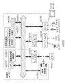
- FIG. 3 is a block diagram of an image coding system using the variable length coding method of the present embodiment.
- the image encoding system 100 includes a prediction unit 101, an encoding control unit 102, a difference unit 103, a conversion unit 104, a quantization unit 105, an inverse quantization unit 106, an inverse conversion unit 107, and an addition unit. 108 and a variable length coding unit 109.
- the prediction unit 101 and the variable length coding unit 109 may include a memory therein.
- the input image signal IMG is input to the prediction unit 101 and the difference unit 103.
- the prediction unit 101 generates a predicted image signal PR from the input image signal IMG and the decoded image signal RIMG that is an already encoded image signal based on the predicted image generation related information PRI input from the encoding control unit 102. . Further, the prediction unit 101 outputs the generated predicted image signal PR to the difference unit 103, and generates the generated predicted image signal PR to the adder unit 108 in order to generate an already encoded image signal. Is also output. Also, the prediction unit 101 outputs a signal indicating the prediction mode used for actual prediction as a signal sequence SE to the encoding control unit 102 and the variable length encoding unit 109.
- the encoding control unit 102 generates predicted image generation related information PRI indicating a method for generating the next predicted image from the prediction mode, and outputs the predicted image generation related information PRI to the prediction unit 101. Furthermore, the encoding control unit 102 outputs information indicating the type (signal type) of the signal sequence SE to the variable length encoding unit 109 as type information SI.
- the predicted image generation related information PRI may be information indicating the positions of the input image signal IMG and the decoded image signal RIMG, for example.
- the signal sequence SE output from the prediction unit 101 is information including position information corresponding to the signal sequence SE.
- the predicted image generation related information PRI may include information on a method for generating a predicted image. In this case, information regarding the generation method is included in the signal sequence SE output from the prediction unit 101.
- the difference unit 103 calculates a difference between the input image signal IMG and the predicted image signal PR, and outputs a signal (difference signal) indicating the difference to the conversion unit 104.
- the conversion unit 104 performs conversion processing (frequency conversion) on the difference signal, and outputs a conversion coefficient generated by the conversion processing to the quantization unit 105.
- the quantization unit 105 performs a quantization process on the transform coefficient, and uses the quantized transform coefficient information generated by the quantization process as a signal sequence SE for the variable length coding unit 109 and the inverse quantization unit 106. Output.
- the inverse quantization unit 106 performs an inverse quantization process on the quantized transform coefficient information, and outputs the transform coefficient generated by the inverse quantization process to the inverse transform unit 107.
- the inverse transform unit 107 performs an inverse transform process (inverse frequency transform) on the transform coefficient, and outputs the decoded residual image signal DR generated by the inverse transform process to the adder unit 108.
- the adding unit 108 adds the decoded residual image signal DR and the predicted image signal PR, and outputs a decoded image signal RIMG generated by the addition to the prediction unit 101.
- the variable length encoding unit 109 performs variable length encoding on the input signal sequence SE based on the type information SI, and outputs a code sequence BS generated by the variable length encoding.
- the variable length coding unit 109 corresponds to an image coding device.
- the variable length encoding unit 109 encodes image information including a plurality of signal sequences SE for each signal (signal sequence SE).
- variable length encoding unit 109 will be described in detail with reference to FIGS.
- FIG. 4 is a block diagram of the variable length coding unit 109.
- the variable length encoding unit 109 includes a control unit 201, a VLC table selection unit 202, a table reference unit 203, a VLC table storage unit 204, and a table update unit 205.
- the control unit 201 determines the table selection information CS corresponding to the type information SI and outputs it to the VLC table selection unit 202.
- the VLC table storage unit 204 stores a plurality of variable length coding (VLC) tables.
- This VLC table shows the signal and a code (code string BS) associated with the signal for each signal (signal string SE).
- code string BS code associated with the signal for each signal
- signal sequence SE is referred to as a symbol.
- the VLC table selection unit 202 selects a VLC table TI corresponding to the table selection information CS from the plurality of VLC tables stored in the VLC table storage unit 204, and outputs the selected VLC table TI to the table reference unit 203. .
- the table reference unit 203 acquires the VLC table TI selected and output by the VLC table selection unit 202 and the signal sequence SE. Then, the table reference unit 203 searches the VLC table TI for a code corresponding to the signal sequence SE, and outputs the code as a code sequence BS. The table reference unit 203 also displays the table reference result TR as information indicating the code string BS, information indicating the signal string SE, or information indicating the position of the code string BS or the signal string SE in the VLC table TI. Output to the update unit 205.
- the table update unit 205 updates the VLC table TI based on the table reference result TR, deletes the pre-update VLC table stored in the VLC table storage unit 204, and updates the updated VLC table TI to the VLC table storage unit 204. To store.
- FIG. 5 is a flowchart showing the operation of the variable length coding unit 109.
- the variable length encoding unit 109 inputs the input type information SI to the control unit 201 (step S301).
- the control unit 201 determines the table selection information CS corresponding to the type information SI and outputs it to the VLC table selection unit 202 (step S302).
- the VLC table selection unit 202 acquires the VLC table TI corresponding to the table selection information CS from the VLC table storage unit 204, and outputs the acquired VLC table TI to the table reference unit 203 (step S303). Further, the VLC table selection unit 202 outputs the VLC table TI to the table update unit 205.
- the table reference unit 203 searches the acquired VLC table TI for a code corresponding to the input signal sequence SE, and outputs the code as a code sequence BS (step S304).
- the table reference unit 203 outputs a table reference result TR (for example, information indicating the position of the code string BS in the VLC table) to the table update unit 205.
- the table update unit 205 updates the VLC table TI based on the table reference result TR, and rewrites the VLC table TI in the VLC table storage unit 204 (step S305).
- FIG. 6A is a diagram illustrating an example of a plurality of VLC tables
- FIG. 6B is a diagram illustrating an example of a plurality of signal sequences
- 7A to 7C are diagrams illustrating an example of updating the VLC table a when the plurality of signal sequences illustrated in FIG. 6B are variable-length encoded.
- FIG. 8 is a flowchart showing a VLC table update process.
- the VLC table storage unit 204 stores a VLC table indicating a correspondence between a plurality of Codes (code strings) and a plurality of Symbols (signal strings).
- FIG. 6B shows an example of a plurality of signal sequences input to the variable length coding unit 109.
- Information indicated by sX indicates a signal sequence (symbol).
- the information indicated by [y] indicates that the VLC table y corresponding to the type information SI of the signal sequence is used for the immediately preceding signal sequence.
- the VLC table used for encoding the first signal sequence s3 is the VLC table a indicated by Code [a] in FIG. 6A.
- the signal sequences s3, s7, s6, s7, and s6 are variable-length encoded using the VLC table a
- the signal sequences s5 and s1 are variable using the VLC table b
- the signal sequence s2 is variable-length encoded using the VLC table c.
- 7A to 7B show an example of updating the VLC table a when the VLC table a is referred to and the code sequences are variable-length encoded in the order of the signal sequences s3, s7, s6, s7, and s6. Yes.
- FIG. 7A shows an example of update when the update table 501 is used
- FIG. 7B shows an example of update when the update table 508 is used.
- the table reference unit 203 first refers to the code string associated with the signal string s3 in the VLC table 502, and outputs “01” that is the code string.
- the signal sequence s3 is encoded into the code sequence “01”.
- the table update unit 205 refers to the update table 501 corresponding to the signal sequence s3 in order to update the VLC table 502 (step S601).
- the update width (update width corresponding to the code string “01”) where the signal string s3 is located is “+1” as described in the update table 501.
- the table updating unit 205 updates the table value (position) for the signal sequence s3 (step S602). That is, the table update unit 205 updates the code string associated with the signal string s3 from “01” to “10”.
- the table update unit 205 updates the position of the signal sequence s2. That is, since the positions of signal sequences other than the referenced signal sequence need to be moved down one by one, the table update unit 205 updates the table value for the signal sequence s2 (step S603).
- the table update unit 205 performs an update that lowers the table value of the signal sequence that was originally associated with the updated table value (change destination) by one.
- the table update unit 205 ends the update process when the update corresponding to all the signal sequences accompanying the change in the table position of the referenced signal sequence is completed (YES in step S604). If there is a signal sequence that has not been updated yet (NO in step S605), the table updating unit 205 performs an update for lowering the position of the next lower signal sequence.
- the VLC table 502 is updated to the VLC table 503 as described above.
- the table reference unit 203 outputs a code string “00000” for the next signal string s7.
- the table update unit 205 performs update processing, and updates the VLC table 503 to the VLC table 504.
- the encoding process and the VLC table update process are performed.
- the VLC table 504 is updated to the VLC table 505, updated to the VLC table 506, and further updated to the VLC table 507.
- the update table shows an update width for each code or for each position in the update table. Also, in this update table, the update width of the signal sequence for a long code length code is large, and the update width of the signal sequence for a short code length code is small. Accordingly, when a large number of signal sequences (for example, s7 in FIG. 7A) for a code with a long code length are referenced in the initial VLC table 502, the code length of the code for the signal sequence is shortened with a smaller number of updates. Thus, it becomes possible to update the VLC table. As a result, encoding efficiency can be improved.
- the update table is not limited to the update table 501, but may be, for example, the update table 508 illustrated in FIG. 7B.
- the update rate is slower than when the update table 501 is used
- the code sequence for the signal sequence is “01 00000 00000 00001 00001”
- the code length of the code sequence is 22, and the fixed VLC table It is the same as using.
- the specific code sequence is a skip mode signal sequence that indicates the same as the previous encoding method that may be frequently selected in the prediction image generation mode.
- the code sequence for the signal sequence s2 is “0001” in the example of FIG. 7A, but “01” in the example of FIG. 7B, and the code length is shortened. There is also. For example, a portion that is not updated may be provided in the VLC table, such as the update table 515 illustrated in FIG. 7C. By doing in this way, the code length of the code for the signal sequence that tends to be frequently generated as described above can be kept short, so that the coding efficiency can be increased.
- FIG. 9A to FIG. 9F are diagrams showing the processing position and processing order in the screen (picture) when the encoding target image (encoding target picture) is processed in units of blocks.
- FIG. 9A is a diagram illustrating an example in which encoding processing is performed in raster order. After the encoding process of Block A, the encoding process of Block B and Block C is performed. The aforementioned update of the VLC table is also updated according to the encoding order. However, as shown in FIG. 9A, Block A and Block B are at spatially continuous positions, but Block B and Block C are not continuous because Block B is at the screen edge. In such a case, the update result in Block B is not so related to the encoding of Block C.
- the update table for the portion (block) corresponding to the right end of the screen and the other update tables may be changed.
- the update table b is used for the portion corresponding to the right end, and the update table a is used otherwise.
- the update width of the update table b is smaller than the update table a.
- the table update unit 205 sets an end processing update table (update table a) for the processing block (step S802). . If the processing block is not the processing end (NO in step S801), the table update unit 205 sets a normal update table (update table b) for the processing block (step S803). Next, the table update unit 205 refers to the update table corresponding to the signal sequence SE (step S804), and updates the table value based on the update width of the update table (step S805).
- the table updating unit 205 performs an update corresponding to the signal sequence of the change destination (step S806), and determines whether the update corresponding to all the signal sequences has been completed (step S807). If the update has not been completed (NO in step S807), the table update unit 205 further performs an update corresponding to the signal sequence to be changed, and if the update corresponding to all the signal sequences is completed (in step S807). YES), the update process is terminated.
- the influence of the right end block can be reduced from the VLC table used for encoding the left end block, and the encoding efficiency can be increased.
- the update table may be changed depending on the spatial positional relationship.
- the update table a having the largest update width is used, the update table c having the next largest update width is used, and the update table b having the smallest update width is used.
- the coding efficiency can be further increased by changing the update table according to the spatial positional relationship.
- the update width of the update table may be scaled from the spatial positional relationship.
- the update order may be different from the processing order as shown in FIG. 9E.
- it is necessary to hold the leftmost update table but since the update results of adjacent blocks can be used in all blocks, the encoding efficiency can be further improved.
- the VLC table used in BlockJ may be derived by combining the update result of BlockH and the update result of BlockI.
- the code length of the code for each code sequence is 2 for the signal sequence s1 to the signal sequence s3.
- a predetermined VLC table is selected (here, the VLC table 502 is given priority).
- the shortest code length is the code length 3 in the VLC table 502 for the signal sequence s4, the code length 5 in the VLC table 514, and the code length 5 in the VLC table 502 for the signal sequence s6.
- the code length is 3.
- VLC table 502 is given priority here
- the next code length of 4 is assigned to one. Since the remaining code length is 5, the remaining signal sequences s5 and s7 are assigned.
- the VLC table 701 shown in FIG. 9F is used as the first VLC table of BlockJ.
- initial table or the update table may be described in the header portion of the stream, as will be described in an embodiment described later.
- the control unit 201 As a method for determining the table selection information CS from the type information SI by the control unit 201, it may be determined in advance which VLC table is used for each type information SI in the encoding method or the decoding method. Thereby, the VLC table according to the signal type can be used.
- the same VLC table may be used for different type information SI (for example, information on a motion vector used for generating a predicted image and information indicating a generation method of the predicted image). Even if the signal types are different, the signal sequence may have the same distribution. In this case, by sharing the VLC table, the amount of memory required to hold the VLC table while maintaining the coding efficiency Can be reduced.
- SI for example, information on a motion vector used for generating a predicted image and information indicating a generation method of the predicted image.
- FIG. 11 is a block diagram of an image decoding system using the variable length decoding method of the present embodiment.
- the image decoding system 900 includes a variable length decoding unit 901, a decoding control unit 902, an inverse quantization unit 903, an inverse transform unit 904, a prediction unit 905, and an addition unit 906.
- the variable length decoding unit 901 and the prediction unit 905 may include a memory therein.
- the input code string BS (code string BS) is generated by the image coding system 100 using the variable length coding method of the first embodiment.
- the input code string BS is input to the variable length decoding unit 901.
- the variable length decoding unit 901 performs variable length decoding on the code string BS of the type indicated by the type information SI, and transmits the signal sequence SE generated by the variable length decoding to the decoding control unit 902 and the inverse quantization unit 903. Output.
- the signal sequence SE is a quantized transform coefficient
- the inverse quantization unit 903 inversely quantizes the signal sequence SE
- the inverse transform unit 904 inversely transforms the inversely quantized transform coefficient.
- the inverse transform unit 904 outputs the decoded residual image signal DR generated by the inverse transform to the adder 906.
- the decoding control unit 902 outputs the signal sequence SE to the prediction unit 905.
- the prediction unit 905 generates a prediction image signal PR from the output image signal OIMG that has already been decoded and the prediction image generation related information PRI, and outputs the prediction image signal PR to the addition unit 906.
- the adder 906 generates and outputs an output image signal OIMG by adding the decoded residual image signal DR and the predicted image signal PR.
- the decoding control unit 902 outputs type information SI indicating the type of the code string BS to be decoded next to the variable length decoding unit 901.
- variable length decoding unit 901 corresponds to an image decoding device.
- the variable length decoding unit 901 decodes the encoded image information for each code (code string BS) constituting the encoded image information.
- variable length decoding unit 901 will be described in detail with reference to FIG. 12 and FIG.
- FIG. 12 is a block diagram of the variable length decoding unit 901.
- the control unit 1001 determines the table selection information CS corresponding to the type information SI and outputs it to the VLD table selection unit 1002.
- the VLD table storage unit 1004 stores a plurality of variable length decoding (VLD) tables. This VLD table shows, for each code (code string BS), the code and a signal (signal string SE) associated with the code.
- VLD variable length decoding
- the VLD table selection unit 1002 selects a VLD table TI corresponding to the table selection information CS from a plurality of VLD tables stored in the VLD table storage unit 1004, and outputs the selected VLD table TI to the table reference unit 1003. .
- the table reference unit 1003 acquires the VLD table TI selected and output by the VLD table selection unit 1002 and the code string BS. Then, the table reference unit 1003 searches the VLD table TI for a signal corresponding to the code string BS, and outputs the signal as a signal string SE. Further, the table reference unit 1003 displays the table reference result TR as information indicating the signal sequence SE, information indicating the code sequence BS, or information indicating the position of the code sequence BS or the signal sequence SE in the VLD table TI. The data is output to the update unit 1005.
- the table update unit 1005 updates the VLD table TI based on the table reference result TR, deletes the pre-update VLD table stored in the VLD table storage unit 1004, and updates the updated VLD table TI to the VLD table storage unit 1004. To store.
- FIG. 13 is a flowchart showing the operation of the variable length decoding unit 901.
- the variable length decoding unit 901 inputs the input type information SI to the control unit 1001 (step S1101).
- the control unit 1001 determines the table selection information CS corresponding to the type information SI and outputs it to the VLD table selection unit 1002 (step S1102).
- the VLD table selection unit 1002 acquires the VLD table TI corresponding to the table selection information CS from the VLD table storage unit 1004, and outputs the acquired VLD table TI to the table reference unit 1003 (step S1103).
- the VLD table selection unit 1002 outputs the VLD table TI to the table update unit 1005.
- the table reference unit 1003 searches the acquired VLD table TI for a signal corresponding to the input code string BS, and outputs the signal as a signal string SE (step S1104).
- the table reference unit 1003 outputs a table reference result TR (for example, information indicating the position of the code string BS in the VLD table) to the table update unit 1005.
- the table update unit 1005 updates the VLD table TI based on the table reference result TR, and rewrites the VLD table TI in the VLD table storage unit 1004 (step S1105).
- FIG. 14 is a diagram illustrating an example of a plurality of VLD tables
- FIG. 15 is a flowchart illustrating a VLD table update process.
- the VLD table storage unit 1004 stores a VLD table indicating a correspondence between a plurality of Codes (code strings) and a plurality of Symbols (signal strings).
- the variable length decoding unit 901 obtains the type information SI necessary for decoding, extracts the VLD table corresponding to the type information SI from the VLD table storage unit 1004, as in the method described in the first embodiment, A signal sequence SE corresponding to the code sequence BS is output. For example, in the decoding process using the VLD table a shown in FIG. 14, when the code string BS is “001”, the variable length decoding unit 901 outputs the signal string “s4” as the signal string SE. To do.
- variable length decoding unit 901 performs a VLD table update process.
- the update table for updating the VLD table the same image encoding method as in the first embodiment is used. Even when the update table is switched according to the same method as that described in the first embodiment, the update table is switched by the same method.
- the table update unit 1005 refers to the update table corresponding to the code string BS (step S1301).
- the table update unit 1005 updates the table value (position) for the signal sequence SE (in the above example, the signal sequence “s4”) based on the update width indicated by the update table (step S1302).
- the table updating unit 1005 updates the table value of the signal sequence originally associated with the updated table value (change destination) with the update of the table value for the signal sequence SE. Update by one is performed (step S1303).
- the table updating unit 1005 performs further updating when updating for all signal sequences is not completed (NO in step S1304).
- the table update unit 1005 ends the VLD table update process.
- the VLC table or the VLD table is updated every time a predetermined processing unit is generated, not every time a code string or a signal string is generated.
- This processing unit includes a plurality of code sequences or signal sequences, and is, for example, a CU (Coding Unit) or an LCU (Largest Coding Unit).
- FIG. 16A is a block diagram showing a configuration of an image encoding device according to the present embodiment.
- the image encoding device 10 is a device that encodes image information for each signal (signal sequence SE) constituting image information, and includes a signal acquisition unit 10a, a reference unit 10b, a count unit 10c, And an updating unit 10d.
- the image coding apparatus 10 is provided in the image coding system 100 of the first embodiment instead of the variable length coding unit 109 of the first embodiment.
- the signal acquisition unit 10a acquires the signal sequence SE from the image information as an encoding target signal.
- the reference unit 10b acquires and outputs the code string BS associated with the encoding target signal SE from the VLC table indicating the signal string and the code string associated with the signal string for each signal string. .
- the count unit 10c counts the number of times that the code sequence associated with the signal sequence is acquired.
- the updating unit 10d updates the association between the code string and the signal string in the VLC table according to the counted number of times. Note that the update unit 10d updates the association of the VLC table when a predetermined processing unit (eg, CU or LCU) including a plurality of signal sequences in the image information is decoded.
- a predetermined processing unit eg, CU or LCU
- FIG. 16B is a flowchart showing the operation of the image encoding device 10 according to the present embodiment.
- the signal acquisition unit 10a acquires the signal sequence SE from the image information as an encoding target signal (step S10a).
- the reference unit 10b acquires and outputs a code string BS, which is a code associated with the encoding target signal SE, from the VLC table (step S10b).
- the count unit 10c counts, for each signal sequence in the VLC table, the number of times (the number of occurrences) that the code sequence associated with the signal sequence has been acquired (step S10c).
- the updating unit 10d updates the association between the code string and the signal string in the VLC table according to the counted number of occurrences (step S10d).
- FIG. 17A is a diagram illustrating an example of the number of occurrences counted for each signal string in the VLC table.
- FIG. 17B is a diagram illustrating an example of a VLC table updated according to the number of occurrences.
- the update unit 10d updates the VLC table so that a signal sequence having a greater number of occurrences is associated with a code sequence having a shorter code length. For example, as illustrated in FIG. 17A, when the signal sequence “s2” has the largest number of occurrences, the update unit 10d associates the code “11” having the shortest code length with the signal sequence “s2”. Update the VLC table as For example, as illustrated in FIG. 17A, when the signal sequence “s3” has the smallest number of occurrences, the update unit 10d sets the code “00000” having the longest code length for the signal sequence “s3”. The VLC table is updated so as to be associated.
- the processing unit may be a block unit or a single line. Further, for parallel processing, the processing timing may be shifted to the timing when information necessary for encoding is gathered. By doing so, the circuit scale can be reduced.
- the VLC table is updated based on the information accumulated in this way (the number of occurrences counted) (hereinafter referred to as accumulation update), and the VLC table is updated by the method described in the first embodiment. (Hereinafter referred to as sequential update) may be mixed.
- the VLC table is sequentially updated as in the first embodiment, and information indicating the prediction mode (signal sequence) is accumulated, for example. It may be updated. Thereby, the update process according to the characteristic is enabled, and further encoding efficiency can be improved.
- the image encoding device 10 When the image encoding device 10 performs sequential update and accumulation update, the image encoding device 10 includes the control unit 201 of the variable length encoding unit 109, the VLC table selection unit 202, and A VLC table storage unit 204 is provided.
- the update unit 10 d has the function of the table update unit 205
- the reference unit 10 b has the function of the table reference unit 203.
- FIG. 18 is a flowchart showing the operation of the image encoding device 10 that performs sequential update and accumulated update.
- the control unit 201 of the image encoding device 10 checks whether the type information SI is for accumulation update (step S1501). That is, the control unit 201 determines whether or not the signal sequence SE of the type indicated by the type information SI is used for accumulation update. If the control unit 201 determines that the update is for accumulation update (YES in step S1501), the control unit 201 instructs the signal acquisition unit 10a, the reference unit 10b, the count unit 10c, and the update unit 10d to perform accumulation update. As a result, the count unit 10c accumulates the call history of the signal sequence SE (step S1502). That is, the count unit 10c increases the number of occurrences for the signal sequence SE by one.
- the update unit 10d determines whether or not the position of the signal sequence SE is the end of the processing unit (step S1504). If it is determined that it is the end (YES in step S1504), the update unit 10d performs table update processing based on the history (step S1505) and clears the history (step S1506). That is, the update unit 10d updates the VLC table according to the number of occurrences counted for each signal string in the VLC table, for example, the number of occurrences shown in FIG. 17A. Then, the count unit 10c resets all occurrences counted for each signal sequence to zero. On the other hand, if the update unit 10d determines that it is not the end of the processing unit in step S1504 (NO in step S1504), it does not perform the table update process.
- step S1501 If it is determined in step S1501 that the type information SI is not for storage update (NO in step S1501), the control unit 201 further checks whether the type information SI is for sequential update (step S1507). Here, if it is determined that the type information SI is for sequential update (YES in step S1507), the image encoding device 10 is configured as the variable length encoding unit 109 of the first embodiment and the first embodiment. A table update process is performed by the same method (step S1503). If it is determined that the type information SI is not for sequential update (NO in step S1507), the image encoding device 10 does not perform table update processing.
- the image coding method since the correspondence shown in the VLC table is updated, it is not necessary to hold many VLC tables, and the memory capacity for holding the VLC tables is suppressed. can do. Furthermore, since the VLC table is updated according to the number of times the code has been acquired (number of occurrences or occurrence frequency), the coding efficiency can be improved.
- FIG. 19A is a block diagram showing a configuration of the image decoding apparatus according to the present embodiment.
- the image decoding device 20 in the present embodiment is a device that decodes the encoded image information for each code (code string BS) constituting the encoded image information, and includes a code acquisition unit 20a, a reference unit 20b, A counting unit 20c and an updating unit 20d are provided.
- the image decoding apparatus 20 is provided in the image decoding system 900 of the second embodiment instead of the variable length decoding unit 901 of the second embodiment.
- the code acquisition unit 20a acquires the code string BS from the encoded image information as a decoding target code.
- the reference unit 20b acquires, as a decoded signal, the signal sequence SE associated with the decoding target code BS from the VLD table indicating the code sequence and the signal sequence associated with the code sequence for each code sequence. Output.
- the count unit 20c counts the number of times that the signal sequence is acquired as a decoded signal for each signal sequence in the VLD table.
- the updating unit 20d updates the association between the code string and the signal string in the VLD table according to the counted number of times.
- the update unit 20d decodes a predetermined processing unit (eg, CU or LCU) including a plurality of codes in the encoded image information, like the update unit 10d of the image encoding device 10 described above.
- a predetermined processing unit eg, CU or LCU
- the association of the VLD table is updated.
- FIG. 19B is a flowchart showing the operation of the image decoding device 20 in the present embodiment.
- the code acquisition unit 20a acquires the code string BS from the encoded image information as a decoding target code (step S20a).
- the reference unit 20b acquires the signal sequence SE associated with the decoding target code BS from the VLD table as a decoded signal and outputs it (step S20b).
- the count unit 20c counts the number of times that the signal sequence is acquired as a decoded signal (number of occurrences) for each signal sequence in the VLD table (step S20c).
- the updating unit 20d updates the association between the code string and the signal string in the VLD table according to the counted number of occurrences (step S20d).
- Such an image decoding device 20 performs basically the same operation as the image encoding device 10, and restores the code string BS generated by the image encoding device 10 to the signal sequence SE. Further, the image decoding apparatus 20 may perform accumulation update and sequential update in the same manner as the image encoding apparatus 10.
- the image decoding apparatus 20 includes a control unit 1001, a VLD table selection unit 1002, and a VLD table storage unit 1004 of the variable length decoding unit 901 according to the second embodiment.
- the updating unit 20d has the function of the table updating unit 1005, and the reference unit 20b has the function of the table reference unit 1003. Further, the image decoding device 20 performs the same operation as that shown in FIG.
- the association shown in the VLD table is updated, it is not necessary to hold many VLD tables, and the memory capacity for holding the VLD tables is suppressed. can do. Furthermore, since the VLD table is updated according to the number of times of signal (symbol) acquisition (occurrence frequency or frequency), encoding efficiency can be improved together with the image encoding method in the present embodiment.
- the image decoding method according to the present embodiment when updating the association of the VLD table, a signal with a larger number of counted times has a shorter code length.
- the VLD table is updated so as to be associated with the code. Thereby, the coding efficiency can be further improved together with the image coding method in the present embodiment.
- the image decoding method according to the present embodiment further corresponds to the type of decoding target code (code string BS) from the VLD table group.
- code string BS type of decoding target code
- the decoded signal is acquired from the reference table, and when the number of occurrences is counted, the number of occurrences is increased by 1 with respect to the decoded signal in the reference table.
- a VLD table corresponding to the type of code string BS is used, so that a VLD table suitable for the characteristics of the code string BS of that type can be used. Efficiency can be improved.
- the image decoding method according to the present embodiment further selects a VLD table update method based on the type of decoding target code. .
- the accumulated update described above is executed when the first update method is selected as the update method.
- the association between the code and the signal in the VLD table is performed by the second update method.
- Update That is, sequential updating is performed.
- the VLD table is set so that the signal is associated with another code shorter than the code associated with the signal. Update.
- the code length of the code string associated with the first signal string is longer than the code length of the code string associated with the second signal string.
- the update width for the first signal sequence is larger than the update width for the second signal sequence.
- another code string is associated with the first signal string.
- the update width is a change amount of the code length or a change amount of the signal position in the VLD table.
- the VLD table is updated based on the update table indicating the update width for each code. Therefore, since the update width is indicated in the update table, the VLD table can be updated easily and appropriately.
- the image decoding method according to the present embodiment further decodes a decoding target code (code string) from the VLD table group.
- a VLD table corresponding to the type of BS) is selected as a reference table.
- different update tables are associated with each VLD table.
- the reference table is updated according to the update table associated with the reference table.
- the VLD table can be updated in accordance with the feature of the code in the encoded image information, and the encoding efficiency can be further improved together with the image encoding method in the present embodiment.
- the image decoding apparatus 20 further depends on the position of the decoding target code in the image from at least one update table. Select the updated table.
- the VLD table is updated according to the selected update table.
- an update table corresponding to the position of the decoding target code in the image is selected.
- the VLD table suitable for the edge of the screen (picture) can be updated, or the code processing in the screen can be performed.
- the VLD table can be updated in accordance with changes in the code generation tendency depending on the order. As a result, the encoding efficiency can be further improved together with the image encoding method in the present embodiment.
- the VLC table or VLD table is not updated directly, but the VLC table or VLD table is indirectly updated by updating the update intermediate table.
- FIG. 20A is a diagram illustrating an example of a plurality of VLC tables.
- FIG. 20B is a diagram illustrating an example of the intermediate table.
- FIG. 20C is a diagram illustrating an example when the update illustrated in FIG. 7A is performed on the intermediate table.
- FIG. 21 is a flowchart showing an update method using an intermediate table.
- the table updating unit 205 updates the number corresponding to the signal string SE (“3” in FIG. 20B) by the method described in the first embodiment.
- the table update unit 205 refers to the update width described in the update table 1601 (step S1701), and changes the order of the numbers in the intermediate table (step S1702). Further, as in the case of the first embodiment, the table updating unit 205 performs an update process for the change destination number (step S1703), and if the process has not been completed for all (NO in step S1704), the update is performed again. The process is performed, and the update process is terminated when the process is completed (YES in step S1704).
- FIG. 22 is a block diagram of the variable length encoding unit 109 in the present embodiment.
- the variable-length encoding unit 109 in the present embodiment has the same configuration as that shown in FIG. 4 of the first embodiment except for the intermediate table storage unit 1801.
- the variable length coding unit 109 according to the present embodiment is the same as the embodiment except that the table exchange unit 205 and the VLC table selection unit 202 exchange data with each other, except that the VLC table storage unit 204 is changed to the intermediate table storage unit 1801. The same operation as described in 1 is performed.
- VLD table storage unit 204 a VLD table group that requires a large amount of information is stored in a read-only memory (VLC table storage unit 204), and only a part necessary for updating can be read and written as an intermediate table (intermediate memory)
- the table can be stored separately in the table storage unit 1801), and the circuit scale can be reduced.
- the same processing can be performed for the image decoding method.
- the same processing can be performed by reversing the code string BS and the signal string SE.
- an intermediate table indicating the arrangement of a plurality of signals (the above numbers) is further read from the VLD table recorded on the recording medium.
- the association of the VLD table is updated by changing the arrangement of a plurality of signals in the intermediate table. If the updating method is the same on the encoding side and the decoding side, it is not necessary to match the structure having the intermediate memory.
- table related information TblStr indicating an update table is described as stream header information.
- FIG. 23 is a configuration diagram of encoded image information that is an output in the image encoding method of the present embodiment.
- the encoded image information includes a plurality of the above-described code strings BS.
- the encoded image information is an encoded signal corresponding to a moving image sequence composed of at least one screen (picture), and includes sequence data SeqData that is data of the entire screen, It consists of a sequence header SeqHdr which is data common to all data on the screen.
- the table related information TblStr is information for changing the update table, for example.
- 24A to 24C show an example of the table related information TblStr for changing the update table
- FIG. 25 shows the flow of processing when the table related information TblStr is decrypted.
- FIG. 24A shows an example of syntax including a flag “table_update_change_flg” indicating whether or not there is a change (change data) in the update table. By using this flag, the additional code length when there is no change data (NO in step S2101) can be completed with 1 bit. When this flag is ON, it indicates that the update data of the update table is included (YES in step S2101). In this case, update table change processing “Table update change ()” is called.
- 24B is a syntax that indicates the contents of update table change processing, and includes a flag “update_idx_change_flg” that indicates whether there is a change to the update table.
- this flag is decoded (step S2102).
- the code amount can be reduced by skipping decoding of information for the update table. be able to. It should be noted that the number obtained by excluding the number of types of update tables included in the update table group that is not changed may be set as “table_num”.
- the flag indicates that the update table corresponding to the flag is changed (YES in step S2103).
- the change process “Table update data ()” for each update table is called.
- the syntax shown by FIG. 24C is a syntax which shows the content of the change process for every update table. First, information indicating whether or not the change method is a uniform change method is decoded, and if the value of “fix_update_num” is not “0”, that is, if the change method is a uniform change (YES in step S2104), it becomes a target. A uniform change value for the update table is set, and the update table is changed by a predetermined method.
- the update width is set to “0” for each code string from the code string with the shortest code length to the code string with the third code length in ascending order of the code length. "3" is set for all code strings of the fourth and subsequent code lengths.
- the update table change data is the number obtained by subtracting 1 from the update table row number size “table_size” (fixed by the table). Decrypt the value.
- the change value is encoded as a difference “diff_update_idx” between the change value and the immediately preceding change value.
- the top of the update table (the update width set for the code string with the shortest code length) is always “0”, it is only necessary to perform decoding processing for the number of rows of the update table minus 1 (table size). In this way, the code amount can be reduced.
- step S2105 the change value that is change data for the second index is decoded.
- the size of the difference can be reduced and the amount of codes can be reduced.
- step S2106 the difference from the change value positioned one level is encoded or decoded. Thereby, the value to be encoded or decoded can be reduced, and the amount of codes can be reduced. If the change value (change data) cannot be decoded for all the table sizes (NO in step S2107), the difference is further decoded.
- step S2107 If the decryption of the change value has been completed for all the table sizes (YES in step S2107), it is confirmed whether the decryption of the change data has been completed for all the update tables (step S2108). If it is not finished yet (NO in step S2108), the presence / absence of change data for the next update table is decrypted. If the decryption of the change data for all the update tables has been completed (YES in step S2108), the decryption process for the change data ends.
- the table related information TblStr is information for changing the update table, but may be information for changing the intermediate table.
- the table related information TblStr may be information for restoring a VLD table, for example.
- the information for restoration is information used to restore the original VLD table when information is lost due to some influence during decoding.
- the VLD table is updated based on past information as in the above embodiments, subsequent decoding may not be possible when a loss of information occurs.
- the VLD table can be restored by sending the table related information TblStr at a certain period (for example, a block unit, a row unit, or a certain large processing block unit).
- FIGS. 26A to 26C are diagrams illustrating an example of the table related information TblStr when restoring the VLD table.
- FIG. 27 is a flowchart showing a process of decoding the table related information TblStr.
- the syntax illustrated by FIG. 26A is an example of syntax including a flag “table_data_restore_flg” indicating whether there is a change (restoration data) in the VLD table. By using this flag, the additional code length when there is no restored data (NO in step S2301) can be reduced to 1 bit. If this flag is ON, it indicates that restored data is included (YES in step S2301). In this case, the VLD table restoration process “Table restore ()” is called.
- Table restore () is called.
- 26B is a syntax that indicates the contents of the VLD table restoration process, and includes a flag “table_restore_flg” that indicates whether or not there is restoration data for the VLD table.
- this flag is decoded (step S2302).
- the decoding of the restored data for the VLD table is skipped to reduce the code amount. can do.
- the number obtained by excluding those not updated from the number of types of VLD tables included in the VLD table group may be “table_num”.
- the VLD table for information with a small error image (for example, a quantized residual signal) is not restored, and is excluded from the “table_num” target, thereby further reducing the code amount. can do.
- the flag indicates that there is restoration data for the VLD table (YES in step S2303).
- the restoration process “Table data restore ()” for each VLD table is called.
- the syntax shown by FIG. 26C is a syntax which shows the content of the decompression
- the first index is decoded (step S2304).
- the difference “diff_table_data_idx” is decrypted by the number obtained by subtracting 1 from the row number size “table_size” (fixed by the table) of the VLD table (step S2305). In this way, the code amount can be reduced.
- the index is restored by adding the difference that is the decoded data and the previous index (step S2306). If all indexes of the table size (row size) have not been restored (NO in step S2307), the difference is further decoded.
- the restoration of all indexes of the table size is completed (YES in step S2307), it is confirmed whether or not the decoding of the restored data is finished for all the VLD tables. If it is not finished yet (NO in step S2308), the presence / absence of restoration data for the next VLD table is decoded.
- the decoding process for the restored data is finished.
- the sequence header includes table related information TblStr.
- the sequence data SeqData includes a plurality of picture signals PicStr that are encoded signals of one screen (picture).
- the picture signal PicStr is composed of picture data PicData that is data of one screen and a picture header PicHdr that is data common to the entire screen.
- the picture header PicHdr includes table related information TblStr.
- the picture data PicData includes a slice signal SliceStr that is an encoded signal of a slice composed of a set of a plurality of blocks.
- the slice signal SliceStr is composed of slice data SliceData that is data of one slice and a slice header SliceHdr that is data common to all data of one slice.
- the received encoded signal can be correctly decoded in units of slice data SliceData.
- the sequence data SeqData includes a plurality of picture signals PicStr, instead of including the table related information TblStr in all the picture headers PicHdr, the table related information TblStr is included only in some pictures PicHdr. May be.
- the picture data PicData includes a plurality of slice signals SliceStr, instead of including the table related information TblStr in all the slice headers SliceHdr, the table related information TblStr is included only in some slice headers SliceHdr. It may be.
- the table related information TblStr is repeated by substituting the table related information TblStr of the other slice header SliceHdr. It is also possible to suppress the increase in the number of bits due to.
- the header part and the data part other than the header may be separated and transmitted separately. In that case, the header part and the data part do not become one bit stream as shown in FIG.
- the transmission order of the header part and the data part is not continuous, only the header part corresponding to the corresponding data part is transmitted in another packet, and it becomes one bit stream. Even if not, the concept is the same as the case of the bit stream described in FIG.
- the code string BS encoded by the above method is decoded by the following procedure.
- the table related information TblStr included in the sequence header SeqHdr is acquired, and each information is held.
- the table related information TblStr included in the picture header PicHdr is acquired, and each information is updated.
- the information included in the sequence header SeqHdr is held as it is.
- the table related information TblStr included in the slice header SliceHdr is acquired, and each information is updated.
- the encoded update table included in the encoded image information is further decoded, and the update by the second update method described above is decoded.
- the VLD table is updated according to the updated table.
- the storage medium may be any medium that can record a program, such as a magnetic disk, an optical disk, a magneto-optical disk, an IC card, and a semiconductor memory.
- FIG. 28 is a diagram showing an overall configuration of a content supply system ex100 that realizes a content distribution service.
- a communication service providing area is divided into desired sizes, and base stations ex106, ex107, ex108, ex109, and ex110, which are fixed wireless stations, are installed in each cell.
- This content supply system ex100 includes a computer ex111, a PDA (Personal Digital Assistant) ex112, a camera ex113, a mobile phone ex114, a game machine ex115 via the Internet ex101, the Internet service provider ex102, the telephone network ex104, and the base stations ex106 to ex110. Etc. are connected.
- PDA Personal Digital Assistant
- each device may be directly connected to the telephone network ex104 without going from the base station ex106, which is a fixed wireless station, to ex110.
- the devices may be directly connected to each other via short-range wireless or the like.
- the camera ex113 is a device that can shoot moving images such as a digital video camera
- the camera ex116 is a device that can shoot still images and movies such as a digital camera.
- the mobile phone ex114 is a GSM (Global System for Mobile Communications) system, a CDMA (Code Division Multiple Access) system, a W-CDMA (Wideband-Code Division Multiple Access) system, an LTE (Long Terminal Evolution) system, an HSPA ( High-speed-Packet-Access) mobile phone or PHS (Personal-Handyphone System), etc.
- GSM Global System for Mobile Communications
- CDMA Code Division Multiple Access
- W-CDMA Wideband-Code Division Multiple Access
- LTE Long Terminal Evolution
- HSPA High-speed-Packet-Access
- PHS Personal-Handyphone System
- the camera ex113 and the like are connected to the streaming server ex103 through the base station ex109 and the telephone network ex104, thereby enabling live distribution and the like.
- live distribution the content (for example, music live video) captured by the user using the camera ex113 is encoded as described in the above embodiments, and transmitted to the streaming server ex103.
- the streaming server ex103 stream-distributes the content data transmitted to the requested client. Examples of the client include a computer ex111, a PDA ex112, a camera ex113, a mobile phone ex114, and a game machine ex115 that can decode the encoded data. Each device that receives the distributed data decodes the received data and reproduces it.
- the captured data may be encoded by the camera ex113, the streaming server ex103 that performs data transmission processing, or may be shared with each other.
- the decryption processing of the distributed data may be performed by the client, the streaming server ex103, or may be performed in common with each other.
- still images and / or moving image data captured by the camera ex116 may be transmitted to the streaming server ex103 via the computer ex111.
- the encoding process in this case may be performed by any of the camera ex116, the computer ex111, and the streaming server ex103, or may be performed in a shared manner.
- these encoding / decoding processes are generally performed in the computer ex111 and the LSI ex500 included in each device.
- the LSI ex500 may be configured as a single chip or a plurality of chips.
- moving image encoding / decoding software is incorporated into some recording medium (CD-ROM, flexible disk, hard disk, etc.) that can be read by the computer ex111, etc., and encoding / decoding processing is performed using the software. May be.
- moving image data acquired by the camera may be transmitted.
- the moving image data at this time is data encoded by the LSI ex500 included in the mobile phone ex114.
- the streaming server ex103 may be a plurality of servers or a plurality of computers, and may process, record, and distribute data in a distributed manner.
- the encoded data can be received and reproduced by the client.
- the information transmitted by the user can be received, decrypted and reproduced by the client in real time, and personal broadcasting can be realized even for a user who does not have special rights or facilities.
- At least one of the video encoding device and the video decoding device of each of the above embodiments is incorporated in the digital broadcast system ex200. be able to.
- the broadcast station ex201 multiplexed data obtained by multiplexing music data and the like on video data is transmitted to a communication or satellite ex202 via radio waves.
- This video data is data encoded by the moving image encoding method described in the above embodiments.
- the broadcasting satellite ex202 transmits a radio wave for broadcasting, and this radio wave is received by a home antenna ex204 capable of receiving satellite broadcasting.
- the received multiplexed data is decoded and reproduced by a device such as the television (receiver) ex300 or the set top box (STB) ex217.
- a reader / recorder ex218 that reads and decodes multiplexed data recorded on a recording medium ex215 such as a DVD or a BD, or encodes a video signal on the recording medium ex215 and, in some cases, multiplexes and writes it with a music signal. It is possible to mount the moving picture decoding apparatus or moving picture encoding apparatus described in the above embodiments. In this case, the reproduced video signal is displayed on the monitor ex219, and the video signal can be reproduced in another device or system using the recording medium ex215 on which the multiplexed data is recorded.
- a moving picture decoding apparatus may be mounted in a set-top box ex217 connected to a cable ex203 for cable television or an antenna ex204 for satellite / terrestrial broadcasting and displayed on the monitor ex219 of the television.
- the moving picture decoding apparatus may be incorporated in the television instead of the set top box.
- FIG. 30 is a diagram illustrating a television (receiver) ex300 that uses the video decoding method and the video encoding method described in each of the above embodiments.
- the television ex300 obtains or outputs multiplexed data in which audio data is multiplexed with video data via the antenna ex204 or the cable ex203 that receives the broadcast, and demodulates the received multiplexed data.
- the modulation / demodulation unit ex302 that modulates multiplexed data to be transmitted to the outside, and the demodulated multiplexed data is separated into video data and audio data, or the video data and audio data encoded by the signal processing unit ex306 Is provided with a multiplexing / demultiplexing unit ex303.
- the television ex300 decodes the audio data and the video data, or encodes each information, the audio signal processing unit ex304, the signal processing unit ex306 including the video signal processing unit ex305, and the decoded audio signal.
- the television ex300 includes an interface unit ex317 including an operation input unit ex312 that receives an input of a user operation.
- the television ex300 includes a control unit ex310 that performs overall control of each unit, and a power supply circuit unit ex311 that supplies power to each unit.
- the interface unit ex317 includes a bridge unit ex313 connected to an external device such as a reader / recorder ex218, a recording unit ex216 such as an SD card, and an external recording unit such as a hard disk.
- a driver ex315 for connecting to a medium, a modem ex316 for connecting to a telephone network, and the like may be included.
- the recording medium ex216 is capable of electrically recording information by using a nonvolatile / volatile semiconductor memory element to be stored.
- Each part of the television ex300 is connected to each other via a synchronous bus.
- the television ex300 receives a user operation from the remote controller ex220 or the like, and demultiplexes the multiplexed data demodulated by the modulation / demodulation unit ex302 by the multiplexing / demultiplexing unit ex303 based on the control of the control unit ex310 having a CPU or the like. Furthermore, in the television ex300, the separated audio data is decoded by the audio signal processing unit ex304, and the separated video data is decoded by the video signal processing unit ex305 using the decoding method described in each of the above embodiments.
- the decoded audio signal and video signal are output from the output unit ex309 to the outside. At the time of output, these signals may be temporarily stored in the buffers ex318, ex319, etc. so that the audio signal and the video signal are reproduced in synchronization. Also, the television ex300 may read multiplexed data from recording media ex215 and ex216 such as a magnetic / optical disk and an SD card, not from broadcasting. Next, a configuration in which the television ex300 encodes an audio signal or a video signal and transmits the signal to the outside or to a recording medium will be described.
- the television ex300 receives a user operation from the remote controller ex220 and the like, encodes an audio signal with the audio signal processing unit ex304, and converts the video signal with the video signal processing unit ex305 based on the control of the control unit ex310. Encoding is performed using the encoding method described in (1).
- the encoded audio signal and video signal are multiplexed by the multiplexing / demultiplexing unit ex303 and output to the outside. When multiplexing, these signals may be temporarily stored in the buffers ex320, ex321, etc. so that the audio signal and the video signal are synchronized.
- a plurality of buffers ex318, ex319, ex320, and ex321 may be provided as illustrated, or one or more buffers may be shared. Further, in addition to the illustrated example, data may be stored in the buffer as a buffer material that prevents system overflow and underflow, for example, between the modulation / demodulation unit ex302 and the multiplexing / demultiplexing unit ex303.
- the television ex300 has a configuration for receiving AV input of a microphone and a camera, and performs encoding processing on the data acquired from them. Also good.
- the television ex300 has been described as a configuration capable of the above-described encoding processing, multiplexing, and external output, but these processing cannot be performed, and only the above-described reception, decoding processing, and external output are possible. It may be a configuration.
- the decoding process or the encoding process may be performed by either the television ex300 or the reader / recorder ex218,
- the reader / recorder ex218 may share with each other.
- FIG. 31 shows a configuration of the information reproducing / recording unit ex400 when data is read from or written to an optical disk.
- the information reproducing / recording unit ex400 includes elements ex401, ex402, ex403, ex404, ex405, ex406, and ex407 described below.
- the optical head ex401 irradiates a laser spot on the recording surface of the recording medium ex215 that is an optical disk to write information, and detects reflected light from the recording surface of the recording medium ex215 to read the information.
- the modulation recording unit ex402 electrically drives a semiconductor laser built in the optical head ex401 and modulates the laser beam according to the recording data.
- the reproduction demodulator ex403 amplifies the reproduction signal obtained by electrically detecting the reflected light from the recording surface by the photodetector built in the optical head ex401, separates and demodulates the signal component recorded on the recording medium ex215, and is necessary To play back information.
- the buffer ex404 temporarily holds information to be recorded on the recording medium ex215 and information reproduced from the recording medium ex215.
- the disk motor ex405 rotates the recording medium ex215.
- the servo controller ex406 moves the optical head ex401 to a predetermined information track while controlling the rotational drive of the disk motor ex405, and performs a laser spot tracking process.
- the system control unit ex407 controls the entire information reproduction / recording unit ex400.
- the system control unit ex407 uses various kinds of information held in the buffer ex404, and generates and adds new information as necessary, and the modulation recording unit ex402, the reproduction demodulation unit This is realized by recording / reproducing information through the optical head ex401 while operating the ex403 and the servo control unit ex406 in a coordinated manner.
- the system control unit ex407 is composed of, for example, a microprocessor, and executes these processes by executing a read / write program.
- the optical head ex401 has been described as irradiating a laser spot.
- a configuration in which higher-density recording is performed using near-field light may be used.
- FIG. 32 shows a schematic diagram of a recording medium ex215 that is an optical disk.
- Guide grooves grooves
- address information indicating the absolute position on the disc is recorded in advance on the information track ex230 by changing the shape of the groove.
- This address information includes information for specifying the position of the recording block ex231 that is a unit for recording data, and the recording block is specified by reproducing the information track ex230 and reading the address information in a recording or reproducing apparatus.
- the recording medium ex215 includes a data recording area ex233, an inner peripheral area ex232, and an outer peripheral area ex234.
- the area used for recording user data is the data recording area ex233, and the inner circumference area ex232 and the outer circumference area ex234 arranged on the inner or outer circumference of the data recording area ex233 are used for specific purposes other than user data recording. Used.
- the information reproducing / recording unit ex400 reads / writes encoded audio data, video data, or multiplexed data obtained by multiplexing these data with respect to the data recording area ex233 of the recording medium ex215.
- an optical disk such as a single-layer DVD or BD has been described as an example.
- the present invention is not limited to these, and an optical disk having a multilayer structure and capable of recording other than the surface may be used.
- an optical disc with a multi-dimensional recording / reproducing structure such as recording information using light of different wavelengths in the same place on the disc, or recording different layers of information from various angles. It may be.
- the car ex210 having the antenna ex205 can receive data from the satellite ex202 and the like, and the moving image can be reproduced on a display device such as the car navigation ex211 that the car ex210 has.
- the configuration of the car navigation ex211 may be, for example, a configuration in which a GPS receiving unit is added in the configuration illustrated in FIG. 30, and the same may be considered for the computer ex111, the mobile phone ex114, and the like.
- FIG. 33A is a diagram illustrating the mobile phone ex114 using the video decoding method and the video encoding method described in the above embodiment.
- the mobile phone ex114 includes an antenna ex350 for transmitting and receiving radio waves to and from the base station ex110, a camera unit ex365 capable of capturing video and still images, a video captured by the camera unit ex365, a video received by the antenna ex350, and the like Is provided with a display unit ex358 such as a liquid crystal display for displaying the decrypted data.
- the mobile phone ex114 further includes a main body unit having an operation key unit ex366, an audio output unit ex357 such as a speaker for outputting audio, an audio input unit ex356 such as a microphone for inputting audio, a captured video,
- an audio input unit ex356 such as a microphone for inputting audio
- a captured video In the memory unit ex367 for storing encoded data or decoded data such as still images, recorded audio, received video, still images, mails, or the like, or an interface unit with a recording medium for storing data
- a slot ex364 is provided.
- the mobile phone ex114 has a power supply circuit part ex361, an operation input control part ex362, and a video signal processing part ex355 with respect to a main control part ex360 that comprehensively controls each part of the main body including the display part ex358 and the operation key part ex366.
- a camera interface unit ex363, an LCD (Liquid Crystal Display) control unit ex359, a modulation / demodulation unit ex352, a multiplexing / demultiplexing unit ex353, an audio signal processing unit ex354, a slot unit ex364, and a memory unit ex367 are connected to each other via a bus ex370. ing.
- the power supply circuit unit ex361 starts up the mobile phone ex114 in an operable state by supplying power from the battery pack to each unit.
- the cellular phone ex114 converts the audio signal collected by the audio input unit ex356 in the voice call mode into a digital audio signal by the audio signal processing unit ex354 based on the control of the main control unit ex360 having a CPU, a ROM, a RAM, and the like. Then, this is subjected to spectrum spread processing by the modulation / demodulation unit ex352, digital-analog conversion processing and frequency conversion processing are performed by the transmission / reception unit ex351, and then transmitted via the antenna ex350.
- the mobile phone ex114 also amplifies the received data received via the antenna ex350 in the voice call mode, performs frequency conversion processing and analog-digital conversion processing, performs spectrum despreading processing by the modulation / demodulation unit ex352, and performs voice signal processing unit After being converted into an analog audio signal by ex354, this is output from the audio output unit ex357.
- the text data of the e-mail input by operating the operation key unit ex366 of the main unit is sent to the main control unit ex360 via the operation input control unit ex362.
- the main control unit ex360 performs spread spectrum processing on the text data in the modulation / demodulation unit ex352, performs digital analog conversion processing and frequency conversion processing in the transmission / reception unit ex351, and then transmits the text data to the base station ex110 via the antenna ex350.
- almost the reverse process is performed on the received data and output to the display unit ex358.
- the video signal processing unit ex355 compresses the video signal supplied from the camera unit ex365 by the moving image encoding method described in the above embodiments.
- the encoded video data is sent to the multiplexing / separating unit ex353.
- the audio signal processing unit ex354 encodes the audio signal picked up by the audio input unit ex356 while the camera unit ex365 images a video, a still image, etc., and sends the encoded audio data to the multiplexing / separating unit ex353. To do.
- the multiplexing / demultiplexing unit ex353 multiplexes the encoded video data supplied from the video signal processing unit ex355 and the encoded audio data supplied from the audio signal processing unit ex354 by a predetermined method, and is obtained as a result.
- the multiplexed data is subjected to spread spectrum processing by the modulation / demodulation unit (modulation / demodulation circuit unit) ex352, digital-analog conversion processing and frequency conversion processing by the transmission / reception unit ex351, and then transmitted via the antenna ex350.
- the multiplexing / separating unit ex353 separates the multiplexed data into a video data bit stream and an audio data bit stream, and performs video signal processing on the video data encoded via the synchronization bus ex370.
- the encoded audio data is supplied to the audio signal processing unit ex354 while being supplied to the unit ex355.
- the video signal processing unit ex355 decodes the video signal by decoding using the video decoding method corresponding to the video encoding method described in each of the above embodiments, and the display unit ex358 via the LCD control unit ex359. From, for example, video and still images included in a moving image file linked to a home page are displayed.
- the audio signal processing unit ex354 decodes the audio signal, and the audio is output from the audio output unit ex357.
- the terminal such as the mobile phone ex114 is referred to as a transmission terminal having only an encoder and a receiving terminal having only a decoder.
- a transmission terminal having only an encoder
- a receiving terminal having only a decoder.
- multiplexed data in which music data is multiplexed with video data is received and transmitted.
- character data related to video is multiplexed. It may be converted data, or may be video data itself instead of multiplexed data.
- the moving picture encoding method or the moving picture decoding method shown in each of the above embodiments can be used in any of the above-described devices / systems. The described effect can be obtained.
- multiplexed data obtained by multiplexing audio data or the like with video data is configured to include identification information indicating which standard the video data conforms to.
- identification information indicating which standard the video data conforms to.
- FIG. 34 is a diagram showing a structure of multiplexed data.
- multiplexed data is obtained by multiplexing one or more of a video stream, an audio stream, a presentation graphics stream (PG), and an interactive graphics stream.
- the video stream indicates the main video and sub-video of the movie
- the audio stream (IG) indicates the main audio portion of the movie and the sub-audio mixed with the main audio
- the presentation graphics stream indicates the subtitles of the movie.
- the main video indicates a normal video displayed on the screen
- the sub-video is a video displayed on a small screen in the main video.
- the interactive graphics stream indicates an interactive screen created by arranging GUI components on the screen.
- the video stream is encoded by the moving image encoding method or apparatus shown in the above embodiments, or the moving image encoding method or apparatus conforming to the conventional standards such as MPEG-2, MPEG4-AVC, and VC-1. ing.
- the audio stream is encoded by a method such as Dolby AC-3, Dolby Digital Plus, MLP, DTS, DTS-HD, or linear PCM.
- Each stream included in the multiplexed data is identified by PID. For example, 0x1011 for video streams used for movie images, 0x1100 to 0x111F for audio streams, 0x1200 to 0x121F for presentation graphics, 0x1400 to 0x141F for interactive graphics streams, 0x1B00 to 0x1B1F are assigned to video streams used for sub-pictures, and 0x1A00 to 0x1A1F are assigned to audio streams used for sub-audio mixed with the main audio.
- FIG. 35 is a diagram schematically showing how multiplexed data is multiplexed.
- a video stream ex235 composed of a plurality of video frames and an audio stream ex238 composed of a plurality of audio frames are converted into PES packet sequences ex236 and ex239, respectively, and converted into TS packets ex237 and ex240.
- the data of the presentation graphics stream ex241 and interactive graphics ex244 are converted into PES packet sequences ex242 and ex245, respectively, and further converted into TS packets ex243 and ex246.
- the multiplexed data ex247 is configured by multiplexing these TS packets into one stream.
- FIG. 36 shows in more detail how the video stream is stored in the PES packet sequence.
- the first row in FIG. 36 shows a video frame sequence of the video stream.
- the second level shows a PES packet sequence.
- a plurality of video presentation units in a video stream are divided into pictures, B pictures, and P pictures, and are stored in the payload of the PES packet.
- Each PES packet has a PES header, and a PTS (Presentation Time-Stamp) that is a display time of a picture and a DTS (Decoding Time-Stamp) that is a decoding time of a picture are stored in the PES header.
- PTS Presentation Time-Stamp
- DTS Decoding Time-Stamp
- FIG. 37 shows the format of TS packets that are finally written in the multiplexed data.
- the TS packet is a 188-byte fixed-length packet composed of a 4-byte TS header having information such as a PID for identifying a stream and a 184-byte TS payload for storing data.
- the PES packet is divided and stored in the TS payload.
- a 4-byte TP_Extra_Header is added to a TS packet, forms a 192-byte source packet, and is written in multiplexed data.
- TP_Extra_Header information such as ATS (Arrival_Time_Stamp) is described.
- ATS indicates the transfer start time of the TS packet to the PID filter of the decoder.
- Source packets are arranged in the multiplexed data as shown in the lower part of FIG. 37, and the number incremented from the head of the multiplexed data is called SPN (source packet number).
- TS packets included in the multiplexed data include PAT (Program Association Table), PMT (Program Map Table), PCR (Program Clock Reference), and the like in addition to each stream such as video / audio / caption.
- PAT indicates what the PID of the PMT used in the multiplexed data is, and the PID of the PAT itself is registered as 0.
- the PMT has the PID of each stream such as video / audio / subtitles included in the multiplexed data and the attribute information of the stream corresponding to each PID, and has various descriptors related to the multiplexed data.
- the descriptor includes copy control information for instructing permission / non-permission of copying of multiplexed data.
- the PCR corresponds to the ATS in which the PCR packet is transferred to the decoder. Contains STC time information.
- FIG. 38 is a diagram for explaining the data structure of the PMT in detail.
- a PMT header describing the length of data included in the PMT is arranged at the head of the PMT.
- a plurality of descriptors related to multiplexed data are arranged.
- the copy control information and the like are described as descriptors.
- a plurality of pieces of stream information regarding each stream included in the multiplexed data are arranged.
- the stream information includes a stream descriptor in which a stream type, a stream PID, and stream attribute information (frame rate, aspect ratio, etc.) are described to identify a compression codec of the stream.
- the multiplexed data is recorded together with the multiplexed data information file.
- the multiplexed data information file is management information of multiplexed data, has a one-to-one correspondence with the multiplexed data, and includes multiplexed data information, stream attribute information, and an entry map.
- the multiplexed data information is composed of a system rate, a reproduction start time, and a reproduction end time.
- the system rate indicates a maximum transfer rate of multiplexed data to a PID filter of a system target decoder described later.
- the ATS interval included in the multiplexed data is set to be equal to or less than the system rate.
- the playback start time is the PTS of the first video frame of the multiplexed data
- the playback end time is set by adding the playback interval for one frame to the PTS of the video frame at the end of the multiplexed data.
- attribute information about each stream included in the multiplexed data is registered for each PID.
- the attribute information has different information for each video stream, audio stream, presentation graphics stream, and interactive graphics stream.
- the video stream attribute information includes the compression codec used to compress the video stream, the resolution of the individual picture data constituting the video stream, the aspect ratio, and the frame rate. It has information such as how much it is.
- the audio stream attribute information includes the compression codec used to compress the audio stream, the number of channels included in the audio stream, the language supported, and the sampling frequency. With information. These pieces of information are used for initialization of the decoder before the player reproduces it.
- the stream type included in the PMT is used.
- video stream attribute information included in the multiplexed data information is used.
- the video encoding shown in each of the above embodiments for the stream type or video stream attribute information included in the PMT.
- FIG. 41 shows the steps of the moving picture decoding method according to the present embodiment.
- step exS100 the stream type included in the PMT or the video stream attribute information included in the multiplexed data information is acquired from the multiplexed data.
- step exS101 it is determined whether or not the stream type or the video stream attribute information indicates multiplexed data generated by the moving picture encoding method or apparatus described in the above embodiments. To do.
- step exS102 the above embodiments are performed. Decoding is performed by the moving picture decoding method shown in the form.
- the conventional information Decoding is performed by a moving image decoding method compliant with the standard.
- FIG. 42 shows a configuration of LSI ex500 that is made into one chip.
- the LSI ex500 includes elements ex501, ex502, ex503, ex504, ex505, ex506, ex507, ex508, and ex509 described below, and each element is connected via a bus ex510.
- the power supply circuit unit ex505 is activated to an operable state by supplying power to each unit when the power supply is on.
- the LSI ex500 when performing the encoding process, performs the microphone ex117 and the camera ex113 by the AV I / O ex509 based on the control of the control unit ex501 including the CPU ex502, the memory controller ex503, the stream controller ex504, the drive frequency control unit ex512, and the like.
- the AV signal is input from the above.
- the input AV signal is temporarily stored in an external memory ex511 such as SDRAM.
- the accumulated data is divided into a plurality of times as appropriate according to the processing amount and the processing speed and sent to the signal processing unit ex507, and the signal processing unit ex507 encodes an audio signal and / or video. Signal encoding is performed.
- the encoding process of the video signal is the encoding process described in the above embodiments.
- the signal processing unit ex507 further performs processing such as multiplexing the encoded audio data and the encoded video data according to circumstances, and outputs the result from the stream I / Oex 506 to the outside.
- the output multiplexed data is transmitted to the base station ex107 or written to the recording medium ex215. It should be noted that data should be temporarily stored in the buffer ex508 so as to be synchronized when multiplexing.
- the memory ex511 is described as an external configuration of the LSI ex500.
- a configuration included in the LSI ex500 may be used.
- the number of buffers ex508 is not limited to one, and a plurality of buffers may be provided.
- the LSI ex500 may be made into one chip or a plurality of chips.
- control unit ex501 includes the CPU ex502, the memory controller ex503, the stream controller ex504, the drive frequency control unit ex512, and the like, but the configuration of the control unit ex501 is not limited to this configuration.
- the signal processing unit ex507 may further include a CPU.
- the CPU ex502 may be configured to include a signal processing unit ex507 or, for example, an audio signal processing unit that is a part of the signal processing unit ex507.
- the control unit ex501 is configured to include a signal processing unit ex507 or a CPU ex502 having a part thereof.
- LSI LSI
- IC system LSI
- super LSI ultra LSI depending on the degree of integration
- the method of circuit integration is not limited to LSI, and implementation with a dedicated circuit or a general-purpose processor is also possible.
- An FPGA Field Programmable Gate Array
- a reconfigurable processor that can reconfigure the connection and setting of circuit cells inside the LSI may be used.
- FIG. 43 shows a configuration ex800 in the present embodiment.
- the drive frequency switching unit ex803 sets the drive frequency high when the video data is generated by the moving image encoding method or apparatus described in the above embodiments.
- the decoding processing unit ex801 that executes the moving picture decoding method described in each of the above embodiments is instructed to decode the video data.
- the video data is video data compliant with the conventional standard, compared to the case where the video data is generated by the moving picture encoding method or apparatus shown in the above embodiments, Set the drive frequency low. Then, it instructs the decoding processing unit ex802 compliant with the conventional standard to decode the video data.
- the drive frequency switching unit ex803 includes the CPU ex502 and the drive frequency control unit ex512 in FIG.
- the decoding processing unit ex801 that executes the moving picture decoding method shown in each of the above embodiments and the decoding processing unit ex802 that complies with the conventional standard correspond to the signal processing unit ex507 in FIG.
- the CPU ex502 identifies which standard the video data conforms to. Then, based on the signal from the CPU ex502, the drive frequency control unit ex512 sets the drive frequency. Further, based on the signal from the CPU ex502, the signal processing unit ex507 decodes the video data.
- the identification of the video data for example, it is conceivable to use the identification information described in the seventh embodiment.
- the identification information is not limited to that described in Embodiment 7, and any information that can identify which standard the video data conforms to may be used. For example, it is possible to identify which standard the video data conforms to based on an external signal that identifies whether the video data is used for a television or a disk. In some cases, identification may be performed based on such an external signal. In addition, the selection of the driving frequency in the CPU ex502 may be performed based on, for example, a lookup table in which video data standards and driving frequencies are associated with each other as shown in FIG. The look-up table is stored in the buffer ex508 or the internal memory of the LSI, and the CPU ex502 can select the drive frequency by referring to the look-up table.
- FIG. 44 shows steps for executing the method of the present embodiment.
- the signal processing unit ex507 acquires identification information from the multiplexed data.
- the CPU ex502 identifies whether the video data is generated by the encoding method or apparatus described in each of the above embodiments based on the identification information.
- the CPU ex502 sends a signal for setting the drive frequency high to the drive frequency control unit ex512. Then, the drive frequency control unit ex512 sets a high drive frequency.
- step exS203 the CPU ex502 drives the signal for setting the drive frequency low. This is sent to the frequency control unit ex512. Then, in the drive frequency control unit ex512, the drive frequency is set to be lower than that in the case where the video data is generated by the encoding method or apparatus described in the above embodiments.
- the power saving effect can be further enhanced by changing the voltage applied to the LSI ex500 or the device including the LSI ex500 in conjunction with the switching of the driving frequency. For example, when the drive frequency is set low, it is conceivable that the voltage applied to the LSI ex500 or the device including the LSI ex500 is set low as compared with the case where the drive frequency is set high.
- the setting method of the driving frequency may be set to a high driving frequency when the processing amount at the time of decoding is large, and to a low driving frequency when the processing amount at the time of decoding is small. It is not limited to the method.
- the amount of processing for decoding video data compliant with the MPEG4-AVC standard is larger than the amount of processing for decoding video data generated by the moving picture encoding method or apparatus described in the above embodiments. It is conceivable that the setting of the driving frequency is reversed to that in the case described above.
- the method for setting the drive frequency is not limited to the configuration in which the drive frequency is lowered.
- the voltage applied to the LSIex500 or the apparatus including the LSIex500 is set high.
- the driving of the CPU ex502 is stopped.
- the CPU ex502 is temporarily stopped because there is room in processing. Is also possible. Even when the identification information indicates that the video data is generated by the moving image encoding method or apparatus described in each of the above embodiments, if there is a margin for processing, the CPU ex502 is temporarily driven. It can also be stopped. In this case, it is conceivable to set the stop time shorter than in the case where the video data conforms to the conventional standards such as MPEG-2, MPEG4-AVC, and VC-1.
- a plurality of video data that conforms to different standards may be input to the above-described devices and systems such as a television and a mobile phone.
- the signal processing unit ex507 of the LSI ex500 needs to support a plurality of standards in order to be able to decode even when a plurality of video data complying with different standards is input.
- the signal processing unit ex507 corresponding to each standard is used individually, there is a problem that the circuit scale of the LSI ex500 increases and the cost increases.
- a decoding processing unit for executing the moving picture decoding method shown in each of the above embodiments and a decoding conforming to a standard such as MPEG-2, MPEG4-AVC, or VC-1
- the processing unit is partly shared.
- An example of this configuration is shown as ex900 in FIG. 46A.
- the moving picture decoding method shown in each of the above embodiments and the moving picture decoding method compliant with the MPEG4-AVC standard are processed in processes such as entropy coding, inverse quantization, deblocking filter, and motion compensation. Some contents are common.
- the decoding processing unit ex902 corresponding to the MPEG4-AVC standard is shared, and for the other processing content unique to the present invention not corresponding to the MPEG4-AVC standard, the dedicated decoding processing unit ex901 is used.
- Configuration is conceivable.
- the decoding processing unit for executing the moving picture decoding method described in each of the above embodiments is shared, and the processing content specific to the MPEG4-AVC standard As for, a configuration using a dedicated decoding processing unit may be used.
- ex1000 in FIG. 46B shows another example in which processing is partially shared.
- a dedicated decoding processing unit ex1001 corresponding to processing content unique to the present invention
- a dedicated decoding processing unit ex1002 corresponding to processing content specific to other conventional standards
- a moving picture decoding method of the present invention A common decoding processing unit ex1003 corresponding to processing contents common to other conventional video decoding methods is used.
- the dedicated decoding processing units ex1001 and ex1002 are not necessarily specialized in the processing content specific to the present invention or other conventional standards, and may be capable of executing other general-purpose processing.
- the configuration of the present embodiment can be implemented by LSI ex500.
- the circuit scale of the LSI is reduced, and the cost is reduced. It is possible to reduce.
- the present invention is not limited to this.
- some or all of the configurations or processes of Embodiments 1 to 10 may be combined.
- the table update unit and the table reference unit receive the VLC table TI or the VLD table TI from the VLC table selection unit or the VLD table selection unit. Information for identification may be received.
- the table update unit and the table reference unit refer to the VLC table or VLD table identified by the information in the VLC table storage unit or VLD storage unit.
- the image encoding method and the image decoding method according to the present invention have an effect that the encoding efficiency can be improved while suppressing the capacity of the memory. Available for use. Further, the image encoding method and the image decoding method according to the present invention are applied to a high-resolution information display device or an imaging device such as a television, a digital video recorder, a car navigation, a mobile phone, a digital camera, or a digital video camera. It is available and has high utility value.
Abstract
L'invention porte sur un procédé de décodage d'image capable d'augmenter le rendement de codage tout en réduisant la capacité de mémoire. Une chaîne de codes (BS) est acquise à partir d'informations d'image codées à titre de code cible de décodage (S20a) ; un signal de décodage est acquis à partir d'une table VLD et délivré, la table VLD indiquant un code et un signal associé à chaque code individuel, de sorte que le signal de décodage acquis et délivré est un signal correspondant au code cible de décodage (S20b) ; le nombre de fois que le signal est acquis à titre de signal de décodage est compté, relativement à chaque signal dans la table VLD (S20c) ; et l'association entre les codes et les signaux dans la table VLD est mise à jour en fonction du nombre de fois indiqué par le comptage (S20d).
Applications Claiming Priority (2)
| Application Number | Priority Date | Filing Date | Title |
|---|---|---|---|
| JP2010160573 | 2010-07-15 | ||
| JP2010-160573 | 2010-07-15 |
Publications (1)
| Publication Number | Publication Date |
|---|---|
| WO2012008162A1 true WO2012008162A1 (fr) | 2012-01-19 |
Family
ID=45469176
Family Applications (1)
| Application Number | Title | Priority Date | Filing Date |
|---|---|---|---|
| PCT/JP2011/004026 WO2012008162A1 (fr) | 2010-07-15 | 2011-07-14 | Procédé de décodage d'image, procédé de codage d'image, dispositif de décodage d'image, dispositif de codage d'image, programme et circuit intégré |
Country Status (2)
| Country | Link |
|---|---|
| TW (1) | TW201215157A (fr) |
| WO (1) | WO2012008162A1 (fr) |
Citations (6)
| Publication number | Priority date | Publication date | Assignee | Title |
|---|---|---|---|---|
| JPH06291677A (ja) * | 1993-04-02 | 1994-10-18 | Fujitsu Ltd | データ圧縮装置及びデータ復元装置 |
| JPH08116263A (ja) * | 1994-10-17 | 1996-05-07 | Fujitsu Ltd | データ処理装置及びデータ処理方法 |
| JPH08205169A (ja) * | 1995-01-20 | 1996-08-09 | Matsushita Electric Ind Co Ltd | 動画像符号化装置及び復号装置 |
| JP2001094982A (ja) * | 1999-09-20 | 2001-04-06 | Nippon Telegr & Teleph Corp <Ntt> | 階層的画像符号化方法及びその装置と、その方法の実現に用いられるプログラム記録媒体と、階層的画像復号方法及びその装置と、その方法の実現に用いられるプログラム記録媒体 |
| WO2003063503A1 (fr) * | 2002-01-24 | 2003-07-31 | Hitachi, Ltd. | Codage et decodage de signal d'image animee et appareil a cet effet |
| JP2006222980A (ja) * | 1995-10-27 | 2006-08-24 | Toshiba Corp | 画像符号化方法と装置及び画像復号化方法と装置 |
-
2011
- 2011-07-14 WO PCT/JP2011/004026 patent/WO2012008162A1/fr active Application Filing
- 2011-07-14 TW TW100124932A patent/TW201215157A/zh unknown
Patent Citations (6)
| Publication number | Priority date | Publication date | Assignee | Title |
|---|---|---|---|---|
| JPH06291677A (ja) * | 1993-04-02 | 1994-10-18 | Fujitsu Ltd | データ圧縮装置及びデータ復元装置 |
| JPH08116263A (ja) * | 1994-10-17 | 1996-05-07 | Fujitsu Ltd | データ処理装置及びデータ処理方法 |
| JPH08205169A (ja) * | 1995-01-20 | 1996-08-09 | Matsushita Electric Ind Co Ltd | 動画像符号化装置及び復号装置 |
| JP2006222980A (ja) * | 1995-10-27 | 2006-08-24 | Toshiba Corp | 画像符号化方法と装置及び画像復号化方法と装置 |
| JP2001094982A (ja) * | 1999-09-20 | 2001-04-06 | Nippon Telegr & Teleph Corp <Ntt> | 階層的画像符号化方法及びその装置と、その方法の実現に用いられるプログラム記録媒体と、階層的画像復号方法及びその装置と、その方法の実現に用いられるプログラム記録媒体 |
| WO2003063503A1 (fr) * | 2002-01-24 | 2003-07-31 | Hitachi, Ltd. | Codage et decodage de signal d'image animee et appareil a cet effet |
Also Published As
| Publication number | Publication date |
|---|---|
| TW201215157A (en) | 2012-04-01 |
Similar Documents
| Publication | Publication Date | Title |
|---|---|---|
| JP6298555B2 (ja) | 画像復号方法及び画像復号装置 | |
| WO2013057884A1 (fr) | Procédé de codage d'image, procédé de décodage d'image, dispositif de codage d'image, dispositif de décodage d'image, et dispositif de codage et de décodage d'image | |
| JP5841540B2 (ja) | 画像符号化方法、画像復号方法、画像符号化装置、画像復号装置、プログラム、及び集積回路 | |
| WO2016103542A1 (fr) | Procédé de codage, procédé de décodage, dispositif de codage et dispositif de décodage | |
| JP2014527318A (ja) | 周期的なバッファ記述を用いた、動画像符号化方法、動画像復号方法、動画像符号化装置、及び、動画像復号装置 | |
| JP6414712B2 (ja) | 多数の参照ピクチャを用いる動画像符号化方法、動画像復号方法、動画像符号化装置、および動画像復号方法 | |
| JP5936939B2 (ja) | 画像符号化方法および画像復号化方法 | |
| JP6161008B2 (ja) | 画像符号化方法および画像符号化装置 | |
| JP2014060713A (ja) | 画像復号方法および画像復号装置 | |
| WO2013118485A1 (fr) | Procédé de codage d'image, procédé de décodage d'image, dispositif de codage d'image, dispositif de décodage d'image et dispositif de codage et de décodage d'image | |
| WO2011129090A1 (fr) | Procédé de retrait des distorsions d'encodage, procédé d'encodage, procédé de décodage, dispositif de retrait des distorsions d'encodage, dispositif d'encodage et dispositif de décodage | |
| JP2017055452A (ja) | 算術復号方法および算術符号化方法 | |
| WO2015177966A1 (fr) | Procédé d'encodage d'image et dispositif d'encodage d'image | |
| WO2012098868A1 (fr) | Procédé de codage d'image, procédé de décodage d'image, dispositif de codage d'image, dispositif de décodage d'image et dispositif de codage/décodage d'image | |
| WO2012111331A1 (fr) | Procédé de codage vidéo et procédé de décodage vidéo | |
| JP6002973B2 (ja) | 画像符号化方法および画像復号方法 | |
| JP2020058062A (ja) | 送信方法、受信方法、送信装置及び受信装置 | |
| WO2011132400A1 (fr) | Procédé de codage d'image, et procédé de décodage d'image | |
| WO2013073154A1 (fr) | Procédé de codage et procédé de décodage | |
| WO2012096157A1 (fr) | Procédé de codage d'image, procédé de décodage d'image, dispositif de codage d'image et dispositif de décodage d'image | |
| WO2012042810A1 (fr) | Procédé de codage d'image, procédé de décodage d'image, dispositif de codage d'image, dispositif de décodage d'image et système de traitement d'image | |
| WO2012008162A1 (fr) | Procédé de décodage d'image, procédé de codage d'image, dispositif de décodage d'image, dispositif de codage d'image, programme et circuit intégré | |
| WO2013069258A1 (fr) | Procédé de décodage d'image, procédé de codage d'image, dispositif de décodage d'image, dispositif de codage d'image et dispositif de codage et de décodage d'image | |
| WO2012077349A1 (fr) | Procédé de codage d'image et procédé de décodage d'image |
Legal Events
| Date | Code | Title | Description |
|---|---|---|---|
| 121 | Ep: the epo has been informed by wipo that ep was designated in this application |
Ref document number: 11806495 Country of ref document: EP Kind code of ref document: A1 |
|
| NENP | Non-entry into the national phase |
Ref country code: DE |
|
| 122 | Ep: pct application non-entry in european phase |
Ref document number: 11806495 Country of ref document: EP Kind code of ref document: A1 |
|
| NENP | Non-entry into the national phase |
Ref country code: JP |