WO2012008162A1 - Image decoding method, image encoding method, image decoding device, image encoding device, program, and integrated circuit - Google Patents
Image decoding method, image encoding method, image decoding device, image encoding device, program, and integrated circuit Download PDFInfo
- Publication number
- WO2012008162A1 WO2012008162A1 PCT/JP2011/004026 JP2011004026W WO2012008162A1 WO 2012008162 A1 WO2012008162 A1 WO 2012008162A1 JP 2011004026 W JP2011004026 W JP 2011004026W WO 2012008162 A1 WO2012008162 A1 WO 2012008162A1
- Authority
- WO
- WIPO (PCT)
- Prior art keywords
- signal
- code
- update
- decoding
- unit
- Prior art date
Links
Images


Classifications
-
- H—ELECTRICITY
- H03—ELECTRONIC CIRCUITRY
- H03M—CODING; DECODING; CODE CONVERSION IN GENERAL
- H03M7/00—Conversion of a code where information is represented by a given sequence or number of digits to a code where the same, similar or subset of information is represented by a different sequence or number of digits
- H03M7/30—Compression; Expansion; Suppression of unnecessary data, e.g. redundancy reduction
- H03M7/40—Conversion to or from variable length codes, e.g. Shannon-Fano code, Huffman code, Morse code
- H03M7/42—Conversion to or from variable length codes, e.g. Shannon-Fano code, Huffman code, Morse code using table look-up for the coding or decoding process, e.g. using read-only memory
-
- H—ELECTRICITY
- H04—ELECTRIC COMMUNICATION TECHNIQUE
- H04N—PICTORIAL COMMUNICATION, e.g. TELEVISION
- H04N19/00—Methods or arrangements for coding, decoding, compressing or decompressing digital video signals
- H04N19/44—Decoders specially adapted therefor, e.g. video decoders which are asymmetric with respect to the encoder
-
- H—ELECTRICITY
- H04—ELECTRIC COMMUNICATION TECHNIQUE
- H04N—PICTORIAL COMMUNICATION, e.g. TELEVISION
- H04N19/00—Methods or arrangements for coding, decoding, compressing or decompressing digital video signals
- H04N19/90—Methods or arrangements for coding, decoding, compressing or decompressing digital video signals using coding techniques not provided for in groups H04N19/10-H04N19/85, e.g. fractals
- H04N19/91—Entropy coding, e.g. variable length coding [VLC] or arithmetic coding
Definitions
- the present invention relates to the field of image encoding and image decoding, and more particularly to a method and apparatus for variable length encoding and decoding, which is one of entropy encoding and decoding methods.
- Such a video coding standard is, for example, H.264. ITU-T (International Telecommunication Union Telecommunication Standardization Sector) standard indicated by 26x and ISO / IEC standard indicated by MPEG-x.
- ITU-T International Telecommunication Union Telecommunication Standardization Sector
- ISO / IEC ISO / IEC standard
- MPEG-x MPEG-x
- the latest and most advanced video coding standard is currently H.264. H.264 / AVC or MPEG-4 AVC (see Non-Patent Document 1).
- H.264 / AVC standard is roughly divided into processes of prediction, transformation, quantization, and entropy coding.
- entropy coding reduces redundant information from information used for prediction and quantized information.
- variable length coding As entropy coding, variable length coding, adaptive coding, fixed length coding, and the like are known.
- Variable length coding includes Huffman coding, run length coding, arithmetic coding, and the like.
- a method of referring to an encoding / decoding table based on Huffman encoding has a smaller processing amount than arithmetic encoding or the like.
- FIG. 1 and FIG. 2 are block diagrams of a variable length coding unit and a variable length decoding unit using variable length coding and decoding based on conventional Huffman coding. A conventional operation will be described with reference to FIGS. 1 and 2.
- the encoding target signal sequence SE and the type information SI corresponding to the encoding target signal sequence SE are input to the variable length encoding unit 2400 which is an entropy encoding unit.
- the control unit 2401 outputs the VLC table selection information CS to the VLC table selection unit 2402 by a predetermined method using the type information SI and the already encoded signal sequence SE.
- the VLC table selection unit 2402 selects a VLC table TI from a predetermined VLC table group stored in the VLC table storage unit 2404 based on the VLC table selection information CS, and outputs the VLC table TI to the table reference unit 2403. To do.
- the signal sequence SE to be encoded is input to the table reference unit 2403.
- the table reference unit 2403 converts the signal sequence SE based on the VLC table TI, and outputs a signal generated by the conversion as a code sequence BS. To do.
- the type information SI is information for distinguishing whether the signal sequence SE is, for example, information on the prediction mode of encoding or information on transform coefficients for the residual signal.
- the encoding target signal SE that has already been encoded is, for example, the number of non-zero coefficients of the already encoded conversion coefficients.
- the VLC table selection unit 2402 selects a VLC table designed for a different distribution depending on the number of non-zero coefficients.
- the code string BS to be decoded and the type information SI corresponding to the code string BS are input to the variable length decoding unit 2500 that is an entropy decoding unit.
- the control unit 2501 outputs the VLD table selection information CS to the VLD table selection unit 2502 by a predetermined method using the type information SI and the already decoded signal sequence SE.
- the VLD table selection unit 2502 selects a VLD table TI from a predetermined VLD table group stored in the VLD table storage unit 2504 based on the VLD table selection information CS, and outputs the VLD table TI to the table reference unit 2503. To do.
- the code sequence BS to be decoded is input to the table reference unit 2503, and the table reference unit 2503 converts the code sequence BS based on the VLD table TI and outputs a signal generated by the conversion as a signal SE.
- the already decoded signal sequence SE is, for example, the number of non-zero coefficients of transform coefficients that have already been decoded, and the VLD table selection unit 2502 applies different distributions depending on the number of non-zero coefficients. Select the designed VLD table.
- encoding and decoding according to the characteristics of image data can be realized by switching a plurality of fixed tables based on type information and a signal that has already been encoded or decoded.
- the amount of processing can be reduced as compared with arithmetic coding that realizes variable length coding by arithmetic operation.
- the image encoding method and the image decoding method disclosed in Patent Document 1 have a problem that a memory having a large capacity is required to improve the encoding efficiency. That is, in the above conventional method, a fixed table in which the code length corresponding to the occurrence probability of the symbol (signal sequence SE) is determined in advance is used. Therefore, for example, when the characteristics of the input signal (signal sequence SE or code sequence BS) are greatly different, such as a sports video and a news video, the actual symbol occurrence probability and the symbol occurrence probability predetermined in the table are The coding efficiency is poor.
- an object of the present invention is to provide an image encoding method and an image decoding method capable of improving encoding efficiency while suppressing memory capacity.
- an image decoding method is an image decoding method for decoding encoded image information for each code constituting encoded image information, the code The code is acquired as the decoding target code from the encoded image information, and the signal associated with the decoding target code is obtained from the variable length decoding table indicating the code and the signal associated with the code for each code. Obtained and output as a decoded signal, for each signal in the variable length decoding table, counts the number of times the signal is acquired as a decoded signal, and associates the code and signal in the variable length decoding table And updating according to the counted number of times.
- variable-length decoding table As a result, the correspondence shown in the variable-length decoding table is updated, so there is no need to hold many variable-length decoding tables, and the memory capacity for holding the variable-length decoding table is suppressed. Can do. Furthermore, since the variable length decoding table is updated according to the number of times the signal (symbol) is acquired (number of occurrences or occurrence frequency), the variable length coding table corresponding to the variable length decoding table is also updated. Coding efficiency can be improved by performing the same update.
- variable length decoding table is updated so that a signal having a larger number of counts is associated with a code with a shorter code length.
- variable length decoding table corresponding to the type of the decoding target code is selected as a reference table from at least one variable length decoding table, and the decoded signal is acquired.
- the decoded signal is acquired from the reference table and the number of times is counted, the number of times is increased by 1 with respect to the decoded signal in the reference table.
- variable length decoding table corresponding to the code type since the variable length decoding table corresponding to the code type is used, the variable length decoding table suitable for the characteristics of the code of the type can be used, and the encoding efficiency can be further improved.
- variable length decoding is performed when a predetermined processing unit including a plurality of codes in the encoded image information is decoded. Update the association of the conversion table.
- variable length decoding table is updated, so that the variable length decoding table suitable for the overall characteristics of the processing unit can be updated, and the coding efficiency can be further improved. Can be improved.
- the image decoding method further selects an update method for the variable length decoding table based on a type of the decoding target code, and associates the count with the variable length decoding table.
- the update is performed when the first update method is selected as the update method.
- the image decoding method further includes, when the second update method is selected by the selection of the update method, associating the code and the signal in the variable length decoding table with the second update method.
- the second update method In the update by the second update method, each time a signal is acquired as the decoded signal, the signal is associated with another code shorter than the code associated with the signal.
- the variable length decoding table is updated.
- the code length of the code associated with the first signal in the variable length decoding table is the code length of the code associated with the second signal.
- the update width for the first signal is larger than the update width for the second signal. Associate other codes with the signal.
- the update width is the change amount of the code length or the change amount of the signal position in the variable length decoding table.
- variable length coding table corresponding to the variable length decoding table As a result, the same update is performed for the variable length coding table corresponding to the variable length decoding table, so that many codes having a long code length are likely to be generated in the encoded image information.
- code length of the code can be shortened more quickly, and the encoding efficiency can be further improved.
- variable length decoding table is updated based on an update table indicating an update width for each code.
- variable length decoding table can be updated easily and appropriately.
- the image decoding method further selects a variable length decoding table corresponding to a type of the decoding target code from at least one variable length decoding table as a reference table, and the at least one variable length decoding
- Each update table is associated with the different update tables, and in the update by the second update method, the reference table is updated according to the update table associated with the reference table.
- variable length decoding table can be updated in accordance with the feature of the code in the encoded image information, and the encoding efficiency can be further improved.
- the image decoding method further selects an update table corresponding to a position in the image of the decoding target code from at least one update table, and is selected in the update by the second update method.
- the variable length decoding table is updated according to the update table.
- an update table corresponding to the position of the decoding target code in the image is selected.
- the variable length decoding table suitable for the edge of the screen (picture) can be updated.
- the variable length decoding table can be updated in accordance with the change in the code generation tendency depending on the code processing order, and the encoding efficiency can be further improved.
- the image decoding method further decodes the encoded update table included in the encoded image information, and in the update by the second update method, the decoded update table is added to the decoded update table. In response, the variable length decoding table is updated.
- the image encoding apparatus that generates the encoded image information can include the update table that increases the encoding efficiency in the encoded image information and transmit it to the image decoding apparatus, and further improve the encoding efficiency. be able to.
- the intermediate table indicating the arrangement of a plurality of signals is read from the variable length decoding table recorded on the recording medium, and the correspondence of the variable length decoding table is updated.
- the correspondence of the variable length decoding table is updated by changing the arrangement of the plurality of signals in the intermediate table.
- variable length decoding table with a large amount of information is recorded in a read-only memory or the like, and an intermediate table that is a part of the variable length decoding table is recorded in a readable / writable memory or the like. Therefore, the circuit scale can be reduced.
- an image encoding method is an image encoding method that encodes image information for each signal constituting the image information.
- a signal is acquired as a signal to be encoded, and a code associated with the signal to be encoded is acquired and output from a variable-length encoding table indicating the signal and a code associated with the signal for each signal.
- the number of times the code associated with the signal is acquired is counted, and the correspondence between the code and the signal in the variable length coding table is counted. Update according to the number of times.
- variable-length coding table is updated, so there is no need to hold many variable-length coding tables, and the memory capacity for holding the variable-length coding table is suppressed. Can do. Furthermore, since the variable length coding table is updated according to the number of times the code has been acquired (number of occurrences or occurrence frequency), the coding efficiency can be improved.
- the present invention can be realized not only as such an image encoding method or image decoding method, but also for an apparatus or an integrated circuit that operates according to the method, and for causing a computer to execute the processing operation according to the method.
- the present invention can also be realized as a program and a recording medium for storing the program.
- the image encoding method and the image decoding method of the present invention can improve the encoding efficiency while suppressing the memory capacity.
- FIG. 1 is a block diagram of a conventional variable length coding unit.
- FIG. 2 is a block diagram of a conventional variable length decoding unit.
- FIG. 3 is a block diagram of an image coding system including a variable length coding unit according to Embodiment 1 of the present invention.
- FIG. 4 is a block diagram of the variable length coding unit according to Embodiment 1 of the present invention.
- FIG. 5 is a flowchart showing the operation of the variable length coding unit according to Embodiment 1 of the present invention.
- FIG. 6A is a schematic diagram showing an example of a VLC table group according to Embodiment 1 of the present invention.
- FIG. 6B is a diagram showing an example of a signal sequence according to Embodiment 1 of the present invention.
- FIG. 7A is a schematic diagram showing an example of the flow of updating the VLC table according to Embodiment 1 of the present invention.
- FIG. 7B is a schematic diagram illustrating another example of the flow of updating the VLC table according to Embodiment 1 of the present invention.
- FIG. 7C is a schematic diagram illustrating an example of an update table according to Embodiment 1 of the present invention.
- FIG. 8 is a flowchart showing a VLC table update process according to Embodiment 1 of the present invention.
- FIG. 9A is a diagram schematically showing the processing order of blocks in order to explain the switching of the update table according to Embodiment 1 of the present invention.
- FIG. 9B is a diagram schematically illustrating switching according to the processing order illustrated in FIG.
- FIG. 9A in order to describe switching of the update table according to Embodiment 1 of the present invention.
- FIG. 9C is a diagram schematically illustrating another processing order of blocks in order to explain the switching of the update table according to Embodiment 1 of the present invention.
- FIG. 9D is a diagram schematically illustrating switching according to the processing order illustrated in FIG. 9C in order to describe switching of the update table according to Embodiment 1 of the present invention.
- FIG. 9E is a diagram schematically illustrating another processing order of blocks in order to explain switching of the update table according to Embodiment 1 of the present invention.
- FIG. 9F is a diagram showing an update table for blocks processed in the processing order shown in FIG. 9E in order to explain switching of the update table according to Embodiment 1 of the present invention.
- FIG. 10 is a flowchart showing the VLC table update processing by the update table according to the position in the picture according to the first embodiment of the present invention.
- FIG. 11 is a block diagram of an image decoding system including a variable length decoding unit according to Embodiment 2 of the present invention.
- FIG. 12 is a block diagram of the variable length decoding unit according to Embodiment 2 of the present invention.
- FIG. 13 is a flowchart showing the operation of the variable length decoding unit according to Embodiment 2 of the present invention.
- FIG. 14 is a schematic diagram showing an example of a VLD table group according to Embodiment 2 of the present invention.
- FIG. 15 is a flowchart showing a VLD table update process according to the second embodiment of the present invention.
- FIG. 11 is a block diagram of an image decoding system including a variable length decoding unit according to Embodiment 2 of the present invention.
- FIG. 12 is a block diagram of the variable length decoding unit according to Embodi
- FIG. 16A is a block diagram of an image coding apparatus according to Embodiment 3 of the present invention.
- FIG. 16B is a flowchart showing an operation of the image coding apparatus according to Embodiment 3 of the present invention.
- FIG. 17A is a diagram showing an example of the number of occurrences counted for each signal string in the VLC table according to Embodiment 3 of the present invention.
- FIG. 17B is a diagram showing an example of a VLC table updated according to the number of occurrences according to Embodiment 3 of the present invention.
- FIG. 18 is a flowchart showing a VLC table update process according to Embodiment 3 of the present invention.
- FIG. 19A is a block diagram of an image decoding apparatus according to Embodiment 3 of the present invention.
- FIG. 19B is a flowchart showing an operation of the image decoding apparatus according to Embodiment 3 of the present invention.
- FIG. 20A is a schematic diagram showing an example of a VLC table group according to Embodiment 4 of the present invention.
- FIG. 20B is a schematic diagram showing an example of an intermediate table group according to Embodiment 4 of the present invention.
- FIG. 20C is a schematic diagram illustrating an example of a flow of updating the intermediate table according to the fourth embodiment of this invention.
- FIG. 21 is a flowchart showing the update process of the intermediate table according to the fourth embodiment of the present invention.
- FIG. 22 is a block diagram of a variable length coding unit according to Embodiment 4 of the present invention.
- FIG. 23 is a configuration diagram of encoded image information according to Embodiment 5 of the present invention, in which (a) shows an exemplary configuration of a code string BS of an encoded image corresponding to a moving image sequence, and (b) FIG. 4C shows an example of the structure of sequence data, FIG. 4C shows an example of the structure of picture signal, FIG. 4D shows an example of the structure of picture data, and FIG.
- FIG. 24A is a diagram showing an example of the syntax of table related information for changing an update table according to Embodiment 5 of the present invention.
- FIG. 24B is a diagram showing another example of the syntax of the table related information for changing the update table according to Embodiment 5 of the present invention.
- FIG. 24A is a diagram showing an example of the syntax of table related information for changing an update table according to Embodiment 5 of the present invention.
- FIG. 24B is a diagram showing another example of the syntax of the table related information for changing the update table according to Embodiment 5 of the present invention
- FIG. 24C is a diagram showing another example of the syntax of the table related information for changing the update table according to Embodiment 5 of the present invention.
- FIG. 25 is a flowchart showing update table change processing according to Embodiment 5 of the present invention.
- FIG. 26A is a diagram showing an example of the syntax of table-related information for restoring a VLD table according to Embodiment 5 of the present invention.
- FIG. 26B is a diagram showing another example of the syntax of the table related information for restoring the VLD table according to Embodiment 5 of the present invention.
- FIG. 26C is a diagram illustrating another example of the syntax of the table related information for restoring the VLD table according to Embodiment 5 of the present invention.
- FIG. 26A is a diagram showing an example of the syntax of table-related information for restoring a VLD table according to Embodiment 5 of the present invention.
- FIG. 26B is a diagram showing another example of the syntax of the table related information for restoring the VLD
- FIG. 27 is a flowchart showing a VLD table restoration process according to the fifth embodiment of the present invention.
- FIG. 28 is an overall configuration diagram of a content supply system that implements a content distribution service.
- FIG. 29 is an overall configuration diagram of a digital broadcasting system.
- FIG. 30 is a block diagram illustrating a configuration example of a television.
- FIG. 31 is a block diagram illustrating a configuration example of an information reproducing / recording unit that reads and writes information from and on a recording medium that is an optical disk.
- FIG. 32 is a diagram illustrating a structure example of a recording medium that is an optical disk.
- FIG. 33A is a diagram illustrating an example of a mobile phone.
- FIG. 33B is a block diagram illustrating a configuration example of a mobile phone.
- FIG. 33A is a diagram illustrating an example of a mobile phone.
- FIG. 34 is a diagram showing a structure of multiplexed data.
- FIG. 35 is a diagram schematically showing how each stream is multiplexed in the multiplexed data.
- FIG. 36 is a diagram showing in more detail how the video stream is stored in the PES packet sequence.
- FIG. 37 is a diagram showing the structure of TS packets and source packets in multiplexed data.
- FIG. 38 shows the data structure of the PMT.
- FIG. 39 shows the internal structure of multiplexed data information.
- FIG. 40 shows the internal structure of stream attribute information.
- FIG. 41 is a diagram showing steps for identifying video data.
- FIG. 42 is a block diagram illustrating a configuration example of an integrated circuit that implements the moving picture coding method and the moving picture decoding method according to each embodiment.
- FIG. 42 is a block diagram illustrating a configuration example of an integrated circuit that implements the moving picture coding method and the moving picture decoding method according to each embodiment.
- FIG. 43 is a diagram showing a configuration for switching drive frequencies.
- FIG. 44 is a diagram illustrating steps for identifying video data and switching between driving frequencies.
- FIG. 45 is a diagram illustrating an example of a look-up table in which video data standards are associated with drive frequencies.
- FIG. 46A is a diagram illustrating an example of a configuration for sharing a module of a signal processing unit.
- FIG. 46B is a diagram illustrating another example of a configuration for sharing a module of the signal processing unit.
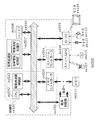
- FIG. 3 is a block diagram of an image coding system using the variable length coding method of the present embodiment.
- the image encoding system 100 includes a prediction unit 101, an encoding control unit 102, a difference unit 103, a conversion unit 104, a quantization unit 105, an inverse quantization unit 106, an inverse conversion unit 107, and an addition unit. 108 and a variable length coding unit 109.
- the prediction unit 101 and the variable length coding unit 109 may include a memory therein.
- the input image signal IMG is input to the prediction unit 101 and the difference unit 103.
- the prediction unit 101 generates a predicted image signal PR from the input image signal IMG and the decoded image signal RIMG that is an already encoded image signal based on the predicted image generation related information PRI input from the encoding control unit 102. . Further, the prediction unit 101 outputs the generated predicted image signal PR to the difference unit 103, and generates the generated predicted image signal PR to the adder unit 108 in order to generate an already encoded image signal. Is also output. Also, the prediction unit 101 outputs a signal indicating the prediction mode used for actual prediction as a signal sequence SE to the encoding control unit 102 and the variable length encoding unit 109.
- the encoding control unit 102 generates predicted image generation related information PRI indicating a method for generating the next predicted image from the prediction mode, and outputs the predicted image generation related information PRI to the prediction unit 101. Furthermore, the encoding control unit 102 outputs information indicating the type (signal type) of the signal sequence SE to the variable length encoding unit 109 as type information SI.
- the predicted image generation related information PRI may be information indicating the positions of the input image signal IMG and the decoded image signal RIMG, for example.
- the signal sequence SE output from the prediction unit 101 is information including position information corresponding to the signal sequence SE.
- the predicted image generation related information PRI may include information on a method for generating a predicted image. In this case, information regarding the generation method is included in the signal sequence SE output from the prediction unit 101.
- the difference unit 103 calculates a difference between the input image signal IMG and the predicted image signal PR, and outputs a signal (difference signal) indicating the difference to the conversion unit 104.
- the conversion unit 104 performs conversion processing (frequency conversion) on the difference signal, and outputs a conversion coefficient generated by the conversion processing to the quantization unit 105.
- the quantization unit 105 performs a quantization process on the transform coefficient, and uses the quantized transform coefficient information generated by the quantization process as a signal sequence SE for the variable length coding unit 109 and the inverse quantization unit 106. Output.
- the inverse quantization unit 106 performs an inverse quantization process on the quantized transform coefficient information, and outputs the transform coefficient generated by the inverse quantization process to the inverse transform unit 107.
- the inverse transform unit 107 performs an inverse transform process (inverse frequency transform) on the transform coefficient, and outputs the decoded residual image signal DR generated by the inverse transform process to the adder unit 108.
- the adding unit 108 adds the decoded residual image signal DR and the predicted image signal PR, and outputs a decoded image signal RIMG generated by the addition to the prediction unit 101.
- the variable length encoding unit 109 performs variable length encoding on the input signal sequence SE based on the type information SI, and outputs a code sequence BS generated by the variable length encoding.
- the variable length coding unit 109 corresponds to an image coding device.
- the variable length encoding unit 109 encodes image information including a plurality of signal sequences SE for each signal (signal sequence SE).
- variable length encoding unit 109 will be described in detail with reference to FIGS.
- FIG. 4 is a block diagram of the variable length coding unit 109.
- the variable length encoding unit 109 includes a control unit 201, a VLC table selection unit 202, a table reference unit 203, a VLC table storage unit 204, and a table update unit 205.
- the control unit 201 determines the table selection information CS corresponding to the type information SI and outputs it to the VLC table selection unit 202.
- the VLC table storage unit 204 stores a plurality of variable length coding (VLC) tables.
- This VLC table shows the signal and a code (code string BS) associated with the signal for each signal (signal string SE).
- code string BS code associated with the signal for each signal
- signal sequence SE is referred to as a symbol.
- the VLC table selection unit 202 selects a VLC table TI corresponding to the table selection information CS from the plurality of VLC tables stored in the VLC table storage unit 204, and outputs the selected VLC table TI to the table reference unit 203. .
- the table reference unit 203 acquires the VLC table TI selected and output by the VLC table selection unit 202 and the signal sequence SE. Then, the table reference unit 203 searches the VLC table TI for a code corresponding to the signal sequence SE, and outputs the code as a code sequence BS. The table reference unit 203 also displays the table reference result TR as information indicating the code string BS, information indicating the signal string SE, or information indicating the position of the code string BS or the signal string SE in the VLC table TI. Output to the update unit 205.
- the table update unit 205 updates the VLC table TI based on the table reference result TR, deletes the pre-update VLC table stored in the VLC table storage unit 204, and updates the updated VLC table TI to the VLC table storage unit 204. To store.
- FIG. 5 is a flowchart showing the operation of the variable length coding unit 109.
- the variable length encoding unit 109 inputs the input type information SI to the control unit 201 (step S301).
- the control unit 201 determines the table selection information CS corresponding to the type information SI and outputs it to the VLC table selection unit 202 (step S302).
- the VLC table selection unit 202 acquires the VLC table TI corresponding to the table selection information CS from the VLC table storage unit 204, and outputs the acquired VLC table TI to the table reference unit 203 (step S303). Further, the VLC table selection unit 202 outputs the VLC table TI to the table update unit 205.
- the table reference unit 203 searches the acquired VLC table TI for a code corresponding to the input signal sequence SE, and outputs the code as a code sequence BS (step S304).
- the table reference unit 203 outputs a table reference result TR (for example, information indicating the position of the code string BS in the VLC table) to the table update unit 205.
- the table update unit 205 updates the VLC table TI based on the table reference result TR, and rewrites the VLC table TI in the VLC table storage unit 204 (step S305).
- FIG. 6A is a diagram illustrating an example of a plurality of VLC tables
- FIG. 6B is a diagram illustrating an example of a plurality of signal sequences
- 7A to 7C are diagrams illustrating an example of updating the VLC table a when the plurality of signal sequences illustrated in FIG. 6B are variable-length encoded.
- FIG. 8 is a flowchart showing a VLC table update process.
- the VLC table storage unit 204 stores a VLC table indicating a correspondence between a plurality of Codes (code strings) and a plurality of Symbols (signal strings).
- FIG. 6B shows an example of a plurality of signal sequences input to the variable length coding unit 109.
- Information indicated by sX indicates a signal sequence (symbol).
- the information indicated by [y] indicates that the VLC table y corresponding to the type information SI of the signal sequence is used for the immediately preceding signal sequence.
- the VLC table used for encoding the first signal sequence s3 is the VLC table a indicated by Code [a] in FIG. 6A.
- the signal sequences s3, s7, s6, s7, and s6 are variable-length encoded using the VLC table a
- the signal sequences s5 and s1 are variable using the VLC table b
- the signal sequence s2 is variable-length encoded using the VLC table c.
- 7A to 7B show an example of updating the VLC table a when the VLC table a is referred to and the code sequences are variable-length encoded in the order of the signal sequences s3, s7, s6, s7, and s6. Yes.
- FIG. 7A shows an example of update when the update table 501 is used
- FIG. 7B shows an example of update when the update table 508 is used.
- the table reference unit 203 first refers to the code string associated with the signal string s3 in the VLC table 502, and outputs “01” that is the code string.
- the signal sequence s3 is encoded into the code sequence “01”.
- the table update unit 205 refers to the update table 501 corresponding to the signal sequence s3 in order to update the VLC table 502 (step S601).
- the update width (update width corresponding to the code string “01”) where the signal string s3 is located is “+1” as described in the update table 501.
- the table updating unit 205 updates the table value (position) for the signal sequence s3 (step S602). That is, the table update unit 205 updates the code string associated with the signal string s3 from “01” to “10”.
- the table update unit 205 updates the position of the signal sequence s2. That is, since the positions of signal sequences other than the referenced signal sequence need to be moved down one by one, the table update unit 205 updates the table value for the signal sequence s2 (step S603).
- the table update unit 205 performs an update that lowers the table value of the signal sequence that was originally associated with the updated table value (change destination) by one.
- the table update unit 205 ends the update process when the update corresponding to all the signal sequences accompanying the change in the table position of the referenced signal sequence is completed (YES in step S604). If there is a signal sequence that has not been updated yet (NO in step S605), the table updating unit 205 performs an update for lowering the position of the next lower signal sequence.
- the VLC table 502 is updated to the VLC table 503 as described above.
- the table reference unit 203 outputs a code string “00000” for the next signal string s7.
- the table update unit 205 performs update processing, and updates the VLC table 503 to the VLC table 504.
- the encoding process and the VLC table update process are performed.
- the VLC table 504 is updated to the VLC table 505, updated to the VLC table 506, and further updated to the VLC table 507.
- the update table shows an update width for each code or for each position in the update table. Also, in this update table, the update width of the signal sequence for a long code length code is large, and the update width of the signal sequence for a short code length code is small. Accordingly, when a large number of signal sequences (for example, s7 in FIG. 7A) for a code with a long code length are referenced in the initial VLC table 502, the code length of the code for the signal sequence is shortened with a smaller number of updates. Thus, it becomes possible to update the VLC table. As a result, encoding efficiency can be improved.
- the update table is not limited to the update table 501, but may be, for example, the update table 508 illustrated in FIG. 7B.
- the update rate is slower than when the update table 501 is used
- the code sequence for the signal sequence is “01 00000 00000 00001 00001”
- the code length of the code sequence is 22, and the fixed VLC table It is the same as using.
- the specific code sequence is a skip mode signal sequence that indicates the same as the previous encoding method that may be frequently selected in the prediction image generation mode.
- the code sequence for the signal sequence s2 is “0001” in the example of FIG. 7A, but “01” in the example of FIG. 7B, and the code length is shortened. There is also. For example, a portion that is not updated may be provided in the VLC table, such as the update table 515 illustrated in FIG. 7C. By doing in this way, the code length of the code for the signal sequence that tends to be frequently generated as described above can be kept short, so that the coding efficiency can be increased.
- FIG. 9A to FIG. 9F are diagrams showing the processing position and processing order in the screen (picture) when the encoding target image (encoding target picture) is processed in units of blocks.
- FIG. 9A is a diagram illustrating an example in which encoding processing is performed in raster order. After the encoding process of Block A, the encoding process of Block B and Block C is performed. The aforementioned update of the VLC table is also updated according to the encoding order. However, as shown in FIG. 9A, Block A and Block B are at spatially continuous positions, but Block B and Block C are not continuous because Block B is at the screen edge. In such a case, the update result in Block B is not so related to the encoding of Block C.
- the update table for the portion (block) corresponding to the right end of the screen and the other update tables may be changed.
- the update table b is used for the portion corresponding to the right end, and the update table a is used otherwise.
- the update width of the update table b is smaller than the update table a.
- the table update unit 205 sets an end processing update table (update table a) for the processing block (step S802). . If the processing block is not the processing end (NO in step S801), the table update unit 205 sets a normal update table (update table b) for the processing block (step S803). Next, the table update unit 205 refers to the update table corresponding to the signal sequence SE (step S804), and updates the table value based on the update width of the update table (step S805).
- the table updating unit 205 performs an update corresponding to the signal sequence of the change destination (step S806), and determines whether the update corresponding to all the signal sequences has been completed (step S807). If the update has not been completed (NO in step S807), the table update unit 205 further performs an update corresponding to the signal sequence to be changed, and if the update corresponding to all the signal sequences is completed (in step S807). YES), the update process is terminated.
- the influence of the right end block can be reduced from the VLC table used for encoding the left end block, and the encoding efficiency can be increased.
- the update table may be changed depending on the spatial positional relationship.
- the update table a having the largest update width is used, the update table c having the next largest update width is used, and the update table b having the smallest update width is used.
- the coding efficiency can be further increased by changing the update table according to the spatial positional relationship.
- the update width of the update table may be scaled from the spatial positional relationship.
- the update order may be different from the processing order as shown in FIG. 9E.
- it is necessary to hold the leftmost update table but since the update results of adjacent blocks can be used in all blocks, the encoding efficiency can be further improved.
- the VLC table used in BlockJ may be derived by combining the update result of BlockH and the update result of BlockI.
- the code length of the code for each code sequence is 2 for the signal sequence s1 to the signal sequence s3.
- a predetermined VLC table is selected (here, the VLC table 502 is given priority).
- the shortest code length is the code length 3 in the VLC table 502 for the signal sequence s4, the code length 5 in the VLC table 514, and the code length 5 in the VLC table 502 for the signal sequence s6.
- the code length is 3.
- VLC table 502 is given priority here
- the next code length of 4 is assigned to one. Since the remaining code length is 5, the remaining signal sequences s5 and s7 are assigned.
- the VLC table 701 shown in FIG. 9F is used as the first VLC table of BlockJ.
- initial table or the update table may be described in the header portion of the stream, as will be described in an embodiment described later.
- the control unit 201 As a method for determining the table selection information CS from the type information SI by the control unit 201, it may be determined in advance which VLC table is used for each type information SI in the encoding method or the decoding method. Thereby, the VLC table according to the signal type can be used.
- the same VLC table may be used for different type information SI (for example, information on a motion vector used for generating a predicted image and information indicating a generation method of the predicted image). Even if the signal types are different, the signal sequence may have the same distribution. In this case, by sharing the VLC table, the amount of memory required to hold the VLC table while maintaining the coding efficiency Can be reduced.
- SI for example, information on a motion vector used for generating a predicted image and information indicating a generation method of the predicted image.
- FIG. 11 is a block diagram of an image decoding system using the variable length decoding method of the present embodiment.
- the image decoding system 900 includes a variable length decoding unit 901, a decoding control unit 902, an inverse quantization unit 903, an inverse transform unit 904, a prediction unit 905, and an addition unit 906.
- the variable length decoding unit 901 and the prediction unit 905 may include a memory therein.
- the input code string BS (code string BS) is generated by the image coding system 100 using the variable length coding method of the first embodiment.
- the input code string BS is input to the variable length decoding unit 901.
- the variable length decoding unit 901 performs variable length decoding on the code string BS of the type indicated by the type information SI, and transmits the signal sequence SE generated by the variable length decoding to the decoding control unit 902 and the inverse quantization unit 903. Output.
- the signal sequence SE is a quantized transform coefficient
- the inverse quantization unit 903 inversely quantizes the signal sequence SE
- the inverse transform unit 904 inversely transforms the inversely quantized transform coefficient.
- the inverse transform unit 904 outputs the decoded residual image signal DR generated by the inverse transform to the adder 906.
- the decoding control unit 902 outputs the signal sequence SE to the prediction unit 905.
- the prediction unit 905 generates a prediction image signal PR from the output image signal OIMG that has already been decoded and the prediction image generation related information PRI, and outputs the prediction image signal PR to the addition unit 906.
- the adder 906 generates and outputs an output image signal OIMG by adding the decoded residual image signal DR and the predicted image signal PR.
- the decoding control unit 902 outputs type information SI indicating the type of the code string BS to be decoded next to the variable length decoding unit 901.
- variable length decoding unit 901 corresponds to an image decoding device.
- the variable length decoding unit 901 decodes the encoded image information for each code (code string BS) constituting the encoded image information.
- variable length decoding unit 901 will be described in detail with reference to FIG. 12 and FIG.
- FIG. 12 is a block diagram of the variable length decoding unit 901.
- the control unit 1001 determines the table selection information CS corresponding to the type information SI and outputs it to the VLD table selection unit 1002.
- the VLD table storage unit 1004 stores a plurality of variable length decoding (VLD) tables. This VLD table shows, for each code (code string BS), the code and a signal (signal string SE) associated with the code.
- VLD variable length decoding
- the VLD table selection unit 1002 selects a VLD table TI corresponding to the table selection information CS from a plurality of VLD tables stored in the VLD table storage unit 1004, and outputs the selected VLD table TI to the table reference unit 1003. .
- the table reference unit 1003 acquires the VLD table TI selected and output by the VLD table selection unit 1002 and the code string BS. Then, the table reference unit 1003 searches the VLD table TI for a signal corresponding to the code string BS, and outputs the signal as a signal string SE. Further, the table reference unit 1003 displays the table reference result TR as information indicating the signal sequence SE, information indicating the code sequence BS, or information indicating the position of the code sequence BS or the signal sequence SE in the VLD table TI. The data is output to the update unit 1005.
- the table update unit 1005 updates the VLD table TI based on the table reference result TR, deletes the pre-update VLD table stored in the VLD table storage unit 1004, and updates the updated VLD table TI to the VLD table storage unit 1004. To store.
- FIG. 13 is a flowchart showing the operation of the variable length decoding unit 901.
- the variable length decoding unit 901 inputs the input type information SI to the control unit 1001 (step S1101).
- the control unit 1001 determines the table selection information CS corresponding to the type information SI and outputs it to the VLD table selection unit 1002 (step S1102).
- the VLD table selection unit 1002 acquires the VLD table TI corresponding to the table selection information CS from the VLD table storage unit 1004, and outputs the acquired VLD table TI to the table reference unit 1003 (step S1103).
- the VLD table selection unit 1002 outputs the VLD table TI to the table update unit 1005.
- the table reference unit 1003 searches the acquired VLD table TI for a signal corresponding to the input code string BS, and outputs the signal as a signal string SE (step S1104).
- the table reference unit 1003 outputs a table reference result TR (for example, information indicating the position of the code string BS in the VLD table) to the table update unit 1005.
- the table update unit 1005 updates the VLD table TI based on the table reference result TR, and rewrites the VLD table TI in the VLD table storage unit 1004 (step S1105).
- FIG. 14 is a diagram illustrating an example of a plurality of VLD tables
- FIG. 15 is a flowchart illustrating a VLD table update process.
- the VLD table storage unit 1004 stores a VLD table indicating a correspondence between a plurality of Codes (code strings) and a plurality of Symbols (signal strings).
- the variable length decoding unit 901 obtains the type information SI necessary for decoding, extracts the VLD table corresponding to the type information SI from the VLD table storage unit 1004, as in the method described in the first embodiment, A signal sequence SE corresponding to the code sequence BS is output. For example, in the decoding process using the VLD table a shown in FIG. 14, when the code string BS is “001”, the variable length decoding unit 901 outputs the signal string “s4” as the signal string SE. To do.
- variable length decoding unit 901 performs a VLD table update process.
- the update table for updating the VLD table the same image encoding method as in the first embodiment is used. Even when the update table is switched according to the same method as that described in the first embodiment, the update table is switched by the same method.
- the table update unit 1005 refers to the update table corresponding to the code string BS (step S1301).
- the table update unit 1005 updates the table value (position) for the signal sequence SE (in the above example, the signal sequence “s4”) based on the update width indicated by the update table (step S1302).
- the table updating unit 1005 updates the table value of the signal sequence originally associated with the updated table value (change destination) with the update of the table value for the signal sequence SE. Update by one is performed (step S1303).
- the table updating unit 1005 performs further updating when updating for all signal sequences is not completed (NO in step S1304).
- the table update unit 1005 ends the VLD table update process.
- the VLC table or the VLD table is updated every time a predetermined processing unit is generated, not every time a code string or a signal string is generated.
- This processing unit includes a plurality of code sequences or signal sequences, and is, for example, a CU (Coding Unit) or an LCU (Largest Coding Unit).
- FIG. 16A is a block diagram showing a configuration of an image encoding device according to the present embodiment.
- the image encoding device 10 is a device that encodes image information for each signal (signal sequence SE) constituting image information, and includes a signal acquisition unit 10a, a reference unit 10b, a count unit 10c, And an updating unit 10d.
- the image coding apparatus 10 is provided in the image coding system 100 of the first embodiment instead of the variable length coding unit 109 of the first embodiment.
- the signal acquisition unit 10a acquires the signal sequence SE from the image information as an encoding target signal.
- the reference unit 10b acquires and outputs the code string BS associated with the encoding target signal SE from the VLC table indicating the signal string and the code string associated with the signal string for each signal string. .
- the count unit 10c counts the number of times that the code sequence associated with the signal sequence is acquired.
- the updating unit 10d updates the association between the code string and the signal string in the VLC table according to the counted number of times. Note that the update unit 10d updates the association of the VLC table when a predetermined processing unit (eg, CU or LCU) including a plurality of signal sequences in the image information is decoded.
- a predetermined processing unit eg, CU or LCU
- FIG. 16B is a flowchart showing the operation of the image encoding device 10 according to the present embodiment.
- the signal acquisition unit 10a acquires the signal sequence SE from the image information as an encoding target signal (step S10a).
- the reference unit 10b acquires and outputs a code string BS, which is a code associated with the encoding target signal SE, from the VLC table (step S10b).
- the count unit 10c counts, for each signal sequence in the VLC table, the number of times (the number of occurrences) that the code sequence associated with the signal sequence has been acquired (step S10c).
- the updating unit 10d updates the association between the code string and the signal string in the VLC table according to the counted number of occurrences (step S10d).
- FIG. 17A is a diagram illustrating an example of the number of occurrences counted for each signal string in the VLC table.
- FIG. 17B is a diagram illustrating an example of a VLC table updated according to the number of occurrences.
- the update unit 10d updates the VLC table so that a signal sequence having a greater number of occurrences is associated with a code sequence having a shorter code length. For example, as illustrated in FIG. 17A, when the signal sequence “s2” has the largest number of occurrences, the update unit 10d associates the code “11” having the shortest code length with the signal sequence “s2”. Update the VLC table as For example, as illustrated in FIG. 17A, when the signal sequence “s3” has the smallest number of occurrences, the update unit 10d sets the code “00000” having the longest code length for the signal sequence “s3”. The VLC table is updated so as to be associated.
- the processing unit may be a block unit or a single line. Further, for parallel processing, the processing timing may be shifted to the timing when information necessary for encoding is gathered. By doing so, the circuit scale can be reduced.
- the VLC table is updated based on the information accumulated in this way (the number of occurrences counted) (hereinafter referred to as accumulation update), and the VLC table is updated by the method described in the first embodiment. (Hereinafter referred to as sequential update) may be mixed.
- the VLC table is sequentially updated as in the first embodiment, and information indicating the prediction mode (signal sequence) is accumulated, for example. It may be updated. Thereby, the update process according to the characteristic is enabled, and further encoding efficiency can be improved.
- the image encoding device 10 When the image encoding device 10 performs sequential update and accumulation update, the image encoding device 10 includes the control unit 201 of the variable length encoding unit 109, the VLC table selection unit 202, and A VLC table storage unit 204 is provided.
- the update unit 10 d has the function of the table update unit 205
- the reference unit 10 b has the function of the table reference unit 203.
- FIG. 18 is a flowchart showing the operation of the image encoding device 10 that performs sequential update and accumulated update.
- the control unit 201 of the image encoding device 10 checks whether the type information SI is for accumulation update (step S1501). That is, the control unit 201 determines whether or not the signal sequence SE of the type indicated by the type information SI is used for accumulation update. If the control unit 201 determines that the update is for accumulation update (YES in step S1501), the control unit 201 instructs the signal acquisition unit 10a, the reference unit 10b, the count unit 10c, and the update unit 10d to perform accumulation update. As a result, the count unit 10c accumulates the call history of the signal sequence SE (step S1502). That is, the count unit 10c increases the number of occurrences for the signal sequence SE by one.
- the update unit 10d determines whether or not the position of the signal sequence SE is the end of the processing unit (step S1504). If it is determined that it is the end (YES in step S1504), the update unit 10d performs table update processing based on the history (step S1505) and clears the history (step S1506). That is, the update unit 10d updates the VLC table according to the number of occurrences counted for each signal string in the VLC table, for example, the number of occurrences shown in FIG. 17A. Then, the count unit 10c resets all occurrences counted for each signal sequence to zero. On the other hand, if the update unit 10d determines that it is not the end of the processing unit in step S1504 (NO in step S1504), it does not perform the table update process.
- step S1501 If it is determined in step S1501 that the type information SI is not for storage update (NO in step S1501), the control unit 201 further checks whether the type information SI is for sequential update (step S1507). Here, if it is determined that the type information SI is for sequential update (YES in step S1507), the image encoding device 10 is configured as the variable length encoding unit 109 of the first embodiment and the first embodiment. A table update process is performed by the same method (step S1503). If it is determined that the type information SI is not for sequential update (NO in step S1507), the image encoding device 10 does not perform table update processing.
- the image coding method since the correspondence shown in the VLC table is updated, it is not necessary to hold many VLC tables, and the memory capacity for holding the VLC tables is suppressed. can do. Furthermore, since the VLC table is updated according to the number of times the code has been acquired (number of occurrences or occurrence frequency), the coding efficiency can be improved.
- FIG. 19A is a block diagram showing a configuration of the image decoding apparatus according to the present embodiment.
- the image decoding device 20 in the present embodiment is a device that decodes the encoded image information for each code (code string BS) constituting the encoded image information, and includes a code acquisition unit 20a, a reference unit 20b, A counting unit 20c and an updating unit 20d are provided.
- the image decoding apparatus 20 is provided in the image decoding system 900 of the second embodiment instead of the variable length decoding unit 901 of the second embodiment.
- the code acquisition unit 20a acquires the code string BS from the encoded image information as a decoding target code.
- the reference unit 20b acquires, as a decoded signal, the signal sequence SE associated with the decoding target code BS from the VLD table indicating the code sequence and the signal sequence associated with the code sequence for each code sequence. Output.
- the count unit 20c counts the number of times that the signal sequence is acquired as a decoded signal for each signal sequence in the VLD table.
- the updating unit 20d updates the association between the code string and the signal string in the VLD table according to the counted number of times.
- the update unit 20d decodes a predetermined processing unit (eg, CU or LCU) including a plurality of codes in the encoded image information, like the update unit 10d of the image encoding device 10 described above.
- a predetermined processing unit eg, CU or LCU
- the association of the VLD table is updated.
- FIG. 19B is a flowchart showing the operation of the image decoding device 20 in the present embodiment.
- the code acquisition unit 20a acquires the code string BS from the encoded image information as a decoding target code (step S20a).
- the reference unit 20b acquires the signal sequence SE associated with the decoding target code BS from the VLD table as a decoded signal and outputs it (step S20b).
- the count unit 20c counts the number of times that the signal sequence is acquired as a decoded signal (number of occurrences) for each signal sequence in the VLD table (step S20c).
- the updating unit 20d updates the association between the code string and the signal string in the VLD table according to the counted number of occurrences (step S20d).
- Such an image decoding device 20 performs basically the same operation as the image encoding device 10, and restores the code string BS generated by the image encoding device 10 to the signal sequence SE. Further, the image decoding apparatus 20 may perform accumulation update and sequential update in the same manner as the image encoding apparatus 10.
- the image decoding apparatus 20 includes a control unit 1001, a VLD table selection unit 1002, and a VLD table storage unit 1004 of the variable length decoding unit 901 according to the second embodiment.
- the updating unit 20d has the function of the table updating unit 1005, and the reference unit 20b has the function of the table reference unit 1003. Further, the image decoding device 20 performs the same operation as that shown in FIG.
- the association shown in the VLD table is updated, it is not necessary to hold many VLD tables, and the memory capacity for holding the VLD tables is suppressed. can do. Furthermore, since the VLD table is updated according to the number of times of signal (symbol) acquisition (occurrence frequency or frequency), encoding efficiency can be improved together with the image encoding method in the present embodiment.
- the image decoding method according to the present embodiment when updating the association of the VLD table, a signal with a larger number of counted times has a shorter code length.
- the VLD table is updated so as to be associated with the code. Thereby, the coding efficiency can be further improved together with the image coding method in the present embodiment.
- the image decoding method according to the present embodiment further corresponds to the type of decoding target code (code string BS) from the VLD table group.
- code string BS type of decoding target code
- the decoded signal is acquired from the reference table, and when the number of occurrences is counted, the number of occurrences is increased by 1 with respect to the decoded signal in the reference table.
- a VLD table corresponding to the type of code string BS is used, so that a VLD table suitable for the characteristics of the code string BS of that type can be used. Efficiency can be improved.
- the image decoding method according to the present embodiment further selects a VLD table update method based on the type of decoding target code. .
- the accumulated update described above is executed when the first update method is selected as the update method.
- the association between the code and the signal in the VLD table is performed by the second update method.
- Update That is, sequential updating is performed.
- the VLD table is set so that the signal is associated with another code shorter than the code associated with the signal. Update.
- the code length of the code string associated with the first signal string is longer than the code length of the code string associated with the second signal string.
- the update width for the first signal sequence is larger than the update width for the second signal sequence.
- another code string is associated with the first signal string.
- the update width is a change amount of the code length or a change amount of the signal position in the VLD table.
- the VLD table is updated based on the update table indicating the update width for each code. Therefore, since the update width is indicated in the update table, the VLD table can be updated easily and appropriately.
- the image decoding method according to the present embodiment further decodes a decoding target code (code string) from the VLD table group.
- a VLD table corresponding to the type of BS) is selected as a reference table.
- different update tables are associated with each VLD table.
- the reference table is updated according to the update table associated with the reference table.
- the VLD table can be updated in accordance with the feature of the code in the encoded image information, and the encoding efficiency can be further improved together with the image encoding method in the present embodiment.
- the image decoding apparatus 20 further depends on the position of the decoding target code in the image from at least one update table. Select the updated table.
- the VLD table is updated according to the selected update table.
- an update table corresponding to the position of the decoding target code in the image is selected.
- the VLD table suitable for the edge of the screen (picture) can be updated, or the code processing in the screen can be performed.
- the VLD table can be updated in accordance with changes in the code generation tendency depending on the order. As a result, the encoding efficiency can be further improved together with the image encoding method in the present embodiment.
- the VLC table or VLD table is not updated directly, but the VLC table or VLD table is indirectly updated by updating the update intermediate table.
- FIG. 20A is a diagram illustrating an example of a plurality of VLC tables.
- FIG. 20B is a diagram illustrating an example of the intermediate table.
- FIG. 20C is a diagram illustrating an example when the update illustrated in FIG. 7A is performed on the intermediate table.
- FIG. 21 is a flowchart showing an update method using an intermediate table.
- the table updating unit 205 updates the number corresponding to the signal string SE (“3” in FIG. 20B) by the method described in the first embodiment.
- the table update unit 205 refers to the update width described in the update table 1601 (step S1701), and changes the order of the numbers in the intermediate table (step S1702). Further, as in the case of the first embodiment, the table updating unit 205 performs an update process for the change destination number (step S1703), and if the process has not been completed for all (NO in step S1704), the update is performed again. The process is performed, and the update process is terminated when the process is completed (YES in step S1704).
- FIG. 22 is a block diagram of the variable length encoding unit 109 in the present embodiment.
- the variable-length encoding unit 109 in the present embodiment has the same configuration as that shown in FIG. 4 of the first embodiment except for the intermediate table storage unit 1801.
- the variable length coding unit 109 according to the present embodiment is the same as the embodiment except that the table exchange unit 205 and the VLC table selection unit 202 exchange data with each other, except that the VLC table storage unit 204 is changed to the intermediate table storage unit 1801. The same operation as described in 1 is performed.
- VLD table storage unit 204 a VLD table group that requires a large amount of information is stored in a read-only memory (VLC table storage unit 204), and only a part necessary for updating can be read and written as an intermediate table (intermediate memory)
- the table can be stored separately in the table storage unit 1801), and the circuit scale can be reduced.
- the same processing can be performed for the image decoding method.
- the same processing can be performed by reversing the code string BS and the signal string SE.
- an intermediate table indicating the arrangement of a plurality of signals (the above numbers) is further read from the VLD table recorded on the recording medium.
- the association of the VLD table is updated by changing the arrangement of a plurality of signals in the intermediate table. If the updating method is the same on the encoding side and the decoding side, it is not necessary to match the structure having the intermediate memory.
- table related information TblStr indicating an update table is described as stream header information.
- FIG. 23 is a configuration diagram of encoded image information that is an output in the image encoding method of the present embodiment.
- the encoded image information includes a plurality of the above-described code strings BS.
- the encoded image information is an encoded signal corresponding to a moving image sequence composed of at least one screen (picture), and includes sequence data SeqData that is data of the entire screen, It consists of a sequence header SeqHdr which is data common to all data on the screen.
- the table related information TblStr is information for changing the update table, for example.
- 24A to 24C show an example of the table related information TblStr for changing the update table
- FIG. 25 shows the flow of processing when the table related information TblStr is decrypted.
- FIG. 24A shows an example of syntax including a flag “table_update_change_flg” indicating whether or not there is a change (change data) in the update table. By using this flag, the additional code length when there is no change data (NO in step S2101) can be completed with 1 bit. When this flag is ON, it indicates that the update data of the update table is included (YES in step S2101). In this case, update table change processing “Table update change ()” is called.
- 24B is a syntax that indicates the contents of update table change processing, and includes a flag “update_idx_change_flg” that indicates whether there is a change to the update table.
- this flag is decoded (step S2102).
- the code amount can be reduced by skipping decoding of information for the update table. be able to. It should be noted that the number obtained by excluding the number of types of update tables included in the update table group that is not changed may be set as “table_num”.
- the flag indicates that the update table corresponding to the flag is changed (YES in step S2103).
- the change process “Table update data ()” for each update table is called.
- the syntax shown by FIG. 24C is a syntax which shows the content of the change process for every update table. First, information indicating whether or not the change method is a uniform change method is decoded, and if the value of “fix_update_num” is not “0”, that is, if the change method is a uniform change (YES in step S2104), it becomes a target. A uniform change value for the update table is set, and the update table is changed by a predetermined method.
- the update width is set to “0” for each code string from the code string with the shortest code length to the code string with the third code length in ascending order of the code length. "3" is set for all code strings of the fourth and subsequent code lengths.
- the update table change data is the number obtained by subtracting 1 from the update table row number size “table_size” (fixed by the table). Decrypt the value.
- the change value is encoded as a difference “diff_update_idx” between the change value and the immediately preceding change value.
- the top of the update table (the update width set for the code string with the shortest code length) is always “0”, it is only necessary to perform decoding processing for the number of rows of the update table minus 1 (table size). In this way, the code amount can be reduced.
- step S2105 the change value that is change data for the second index is decoded.
- the size of the difference can be reduced and the amount of codes can be reduced.
- step S2106 the difference from the change value positioned one level is encoded or decoded. Thereby, the value to be encoded or decoded can be reduced, and the amount of codes can be reduced. If the change value (change data) cannot be decoded for all the table sizes (NO in step S2107), the difference is further decoded.
- step S2107 If the decryption of the change value has been completed for all the table sizes (YES in step S2107), it is confirmed whether the decryption of the change data has been completed for all the update tables (step S2108). If it is not finished yet (NO in step S2108), the presence / absence of change data for the next update table is decrypted. If the decryption of the change data for all the update tables has been completed (YES in step S2108), the decryption process for the change data ends.
- the table related information TblStr is information for changing the update table, but may be information for changing the intermediate table.
- the table related information TblStr may be information for restoring a VLD table, for example.
- the information for restoration is information used to restore the original VLD table when information is lost due to some influence during decoding.
- the VLD table is updated based on past information as in the above embodiments, subsequent decoding may not be possible when a loss of information occurs.
- the VLD table can be restored by sending the table related information TblStr at a certain period (for example, a block unit, a row unit, or a certain large processing block unit).
- FIGS. 26A to 26C are diagrams illustrating an example of the table related information TblStr when restoring the VLD table.
- FIG. 27 is a flowchart showing a process of decoding the table related information TblStr.
- the syntax illustrated by FIG. 26A is an example of syntax including a flag “table_data_restore_flg” indicating whether there is a change (restoration data) in the VLD table. By using this flag, the additional code length when there is no restored data (NO in step S2301) can be reduced to 1 bit. If this flag is ON, it indicates that restored data is included (YES in step S2301). In this case, the VLD table restoration process “Table restore ()” is called.
- Table restore () is called.
- 26B is a syntax that indicates the contents of the VLD table restoration process, and includes a flag “table_restore_flg” that indicates whether or not there is restoration data for the VLD table.
- this flag is decoded (step S2302).
- the decoding of the restored data for the VLD table is skipped to reduce the code amount. can do.
- the number obtained by excluding those not updated from the number of types of VLD tables included in the VLD table group may be “table_num”.
- the VLD table for information with a small error image (for example, a quantized residual signal) is not restored, and is excluded from the “table_num” target, thereby further reducing the code amount. can do.
- the flag indicates that there is restoration data for the VLD table (YES in step S2303).
- the restoration process “Table data restore ()” for each VLD table is called.
- the syntax shown by FIG. 26C is a syntax which shows the content of the decompression
- the first index is decoded (step S2304).
- the difference “diff_table_data_idx” is decrypted by the number obtained by subtracting 1 from the row number size “table_size” (fixed by the table) of the VLD table (step S2305). In this way, the code amount can be reduced.
- the index is restored by adding the difference that is the decoded data and the previous index (step S2306). If all indexes of the table size (row size) have not been restored (NO in step S2307), the difference is further decoded.
- the restoration of all indexes of the table size is completed (YES in step S2307), it is confirmed whether or not the decoding of the restored data is finished for all the VLD tables. If it is not finished yet (NO in step S2308), the presence / absence of restoration data for the next VLD table is decoded.
- the decoding process for the restored data is finished.
- the sequence header includes table related information TblStr.
- the sequence data SeqData includes a plurality of picture signals PicStr that are encoded signals of one screen (picture).
- the picture signal PicStr is composed of picture data PicData that is data of one screen and a picture header PicHdr that is data common to the entire screen.
- the picture header PicHdr includes table related information TblStr.
- the picture data PicData includes a slice signal SliceStr that is an encoded signal of a slice composed of a set of a plurality of blocks.
- the slice signal SliceStr is composed of slice data SliceData that is data of one slice and a slice header SliceHdr that is data common to all data of one slice.
- the received encoded signal can be correctly decoded in units of slice data SliceData.
- the sequence data SeqData includes a plurality of picture signals PicStr, instead of including the table related information TblStr in all the picture headers PicHdr, the table related information TblStr is included only in some pictures PicHdr. May be.
- the picture data PicData includes a plurality of slice signals SliceStr, instead of including the table related information TblStr in all the slice headers SliceHdr, the table related information TblStr is included only in some slice headers SliceHdr. It may be.
- the table related information TblStr is repeated by substituting the table related information TblStr of the other slice header SliceHdr. It is also possible to suppress the increase in the number of bits due to.
- the header part and the data part other than the header may be separated and transmitted separately. In that case, the header part and the data part do not become one bit stream as shown in FIG.
- the transmission order of the header part and the data part is not continuous, only the header part corresponding to the corresponding data part is transmitted in another packet, and it becomes one bit stream. Even if not, the concept is the same as the case of the bit stream described in FIG.
- the code string BS encoded by the above method is decoded by the following procedure.
- the table related information TblStr included in the sequence header SeqHdr is acquired, and each information is held.
- the table related information TblStr included in the picture header PicHdr is acquired, and each information is updated.
- the information included in the sequence header SeqHdr is held as it is.
- the table related information TblStr included in the slice header SliceHdr is acquired, and each information is updated.
- the encoded update table included in the encoded image information is further decoded, and the update by the second update method described above is decoded.
- the VLD table is updated according to the updated table.
- the storage medium may be any medium that can record a program, such as a magnetic disk, an optical disk, a magneto-optical disk, an IC card, and a semiconductor memory.
- FIG. 28 is a diagram showing an overall configuration of a content supply system ex100 that realizes a content distribution service.
- a communication service providing area is divided into desired sizes, and base stations ex106, ex107, ex108, ex109, and ex110, which are fixed wireless stations, are installed in each cell.
- This content supply system ex100 includes a computer ex111, a PDA (Personal Digital Assistant) ex112, a camera ex113, a mobile phone ex114, a game machine ex115 via the Internet ex101, the Internet service provider ex102, the telephone network ex104, and the base stations ex106 to ex110. Etc. are connected.
- PDA Personal Digital Assistant
- each device may be directly connected to the telephone network ex104 without going from the base station ex106, which is a fixed wireless station, to ex110.
- the devices may be directly connected to each other via short-range wireless or the like.
- the camera ex113 is a device that can shoot moving images such as a digital video camera
- the camera ex116 is a device that can shoot still images and movies such as a digital camera.
- the mobile phone ex114 is a GSM (Global System for Mobile Communications) system, a CDMA (Code Division Multiple Access) system, a W-CDMA (Wideband-Code Division Multiple Access) system, an LTE (Long Terminal Evolution) system, an HSPA ( High-speed-Packet-Access) mobile phone or PHS (Personal-Handyphone System), etc.
- GSM Global System for Mobile Communications
- CDMA Code Division Multiple Access
- W-CDMA Wideband-Code Division Multiple Access
- LTE Long Terminal Evolution
- HSPA High-speed-Packet-Access
- PHS Personal-Handyphone System
- the camera ex113 and the like are connected to the streaming server ex103 through the base station ex109 and the telephone network ex104, thereby enabling live distribution and the like.
- live distribution the content (for example, music live video) captured by the user using the camera ex113 is encoded as described in the above embodiments, and transmitted to the streaming server ex103.
- the streaming server ex103 stream-distributes the content data transmitted to the requested client. Examples of the client include a computer ex111, a PDA ex112, a camera ex113, a mobile phone ex114, and a game machine ex115 that can decode the encoded data. Each device that receives the distributed data decodes the received data and reproduces it.
- the captured data may be encoded by the camera ex113, the streaming server ex103 that performs data transmission processing, or may be shared with each other.
- the decryption processing of the distributed data may be performed by the client, the streaming server ex103, or may be performed in common with each other.
- still images and / or moving image data captured by the camera ex116 may be transmitted to the streaming server ex103 via the computer ex111.
- the encoding process in this case may be performed by any of the camera ex116, the computer ex111, and the streaming server ex103, or may be performed in a shared manner.
- these encoding / decoding processes are generally performed in the computer ex111 and the LSI ex500 included in each device.
- the LSI ex500 may be configured as a single chip or a plurality of chips.
- moving image encoding / decoding software is incorporated into some recording medium (CD-ROM, flexible disk, hard disk, etc.) that can be read by the computer ex111, etc., and encoding / decoding processing is performed using the software. May be.
- moving image data acquired by the camera may be transmitted.
- the moving image data at this time is data encoded by the LSI ex500 included in the mobile phone ex114.
- the streaming server ex103 may be a plurality of servers or a plurality of computers, and may process, record, and distribute data in a distributed manner.
- the encoded data can be received and reproduced by the client.
- the information transmitted by the user can be received, decrypted and reproduced by the client in real time, and personal broadcasting can be realized even for a user who does not have special rights or facilities.
- At least one of the video encoding device and the video decoding device of each of the above embodiments is incorporated in the digital broadcast system ex200. be able to.
- the broadcast station ex201 multiplexed data obtained by multiplexing music data and the like on video data is transmitted to a communication or satellite ex202 via radio waves.
- This video data is data encoded by the moving image encoding method described in the above embodiments.
- the broadcasting satellite ex202 transmits a radio wave for broadcasting, and this radio wave is received by a home antenna ex204 capable of receiving satellite broadcasting.
- the received multiplexed data is decoded and reproduced by a device such as the television (receiver) ex300 or the set top box (STB) ex217.
- a reader / recorder ex218 that reads and decodes multiplexed data recorded on a recording medium ex215 such as a DVD or a BD, or encodes a video signal on the recording medium ex215 and, in some cases, multiplexes and writes it with a music signal. It is possible to mount the moving picture decoding apparatus or moving picture encoding apparatus described in the above embodiments. In this case, the reproduced video signal is displayed on the monitor ex219, and the video signal can be reproduced in another device or system using the recording medium ex215 on which the multiplexed data is recorded.
- a moving picture decoding apparatus may be mounted in a set-top box ex217 connected to a cable ex203 for cable television or an antenna ex204 for satellite / terrestrial broadcasting and displayed on the monitor ex219 of the television.
- the moving picture decoding apparatus may be incorporated in the television instead of the set top box.
- FIG. 30 is a diagram illustrating a television (receiver) ex300 that uses the video decoding method and the video encoding method described in each of the above embodiments.
- the television ex300 obtains or outputs multiplexed data in which audio data is multiplexed with video data via the antenna ex204 or the cable ex203 that receives the broadcast, and demodulates the received multiplexed data.
- the modulation / demodulation unit ex302 that modulates multiplexed data to be transmitted to the outside, and the demodulated multiplexed data is separated into video data and audio data, or the video data and audio data encoded by the signal processing unit ex306 Is provided with a multiplexing / demultiplexing unit ex303.
- the television ex300 decodes the audio data and the video data, or encodes each information, the audio signal processing unit ex304, the signal processing unit ex306 including the video signal processing unit ex305, and the decoded audio signal.
- the television ex300 includes an interface unit ex317 including an operation input unit ex312 that receives an input of a user operation.
- the television ex300 includes a control unit ex310 that performs overall control of each unit, and a power supply circuit unit ex311 that supplies power to each unit.
- the interface unit ex317 includes a bridge unit ex313 connected to an external device such as a reader / recorder ex218, a recording unit ex216 such as an SD card, and an external recording unit such as a hard disk.
- a driver ex315 for connecting to a medium, a modem ex316 for connecting to a telephone network, and the like may be included.
- the recording medium ex216 is capable of electrically recording information by using a nonvolatile / volatile semiconductor memory element to be stored.
- Each part of the television ex300 is connected to each other via a synchronous bus.
- the television ex300 receives a user operation from the remote controller ex220 or the like, and demultiplexes the multiplexed data demodulated by the modulation / demodulation unit ex302 by the multiplexing / demultiplexing unit ex303 based on the control of the control unit ex310 having a CPU or the like. Furthermore, in the television ex300, the separated audio data is decoded by the audio signal processing unit ex304, and the separated video data is decoded by the video signal processing unit ex305 using the decoding method described in each of the above embodiments.
- the decoded audio signal and video signal are output from the output unit ex309 to the outside. At the time of output, these signals may be temporarily stored in the buffers ex318, ex319, etc. so that the audio signal and the video signal are reproduced in synchronization. Also, the television ex300 may read multiplexed data from recording media ex215 and ex216 such as a magnetic / optical disk and an SD card, not from broadcasting. Next, a configuration in which the television ex300 encodes an audio signal or a video signal and transmits the signal to the outside or to a recording medium will be described.
- the television ex300 receives a user operation from the remote controller ex220 and the like, encodes an audio signal with the audio signal processing unit ex304, and converts the video signal with the video signal processing unit ex305 based on the control of the control unit ex310. Encoding is performed using the encoding method described in (1).
- the encoded audio signal and video signal are multiplexed by the multiplexing / demultiplexing unit ex303 and output to the outside. When multiplexing, these signals may be temporarily stored in the buffers ex320, ex321, etc. so that the audio signal and the video signal are synchronized.
- a plurality of buffers ex318, ex319, ex320, and ex321 may be provided as illustrated, or one or more buffers may be shared. Further, in addition to the illustrated example, data may be stored in the buffer as a buffer material that prevents system overflow and underflow, for example, between the modulation / demodulation unit ex302 and the multiplexing / demultiplexing unit ex303.
- the television ex300 has a configuration for receiving AV input of a microphone and a camera, and performs encoding processing on the data acquired from them. Also good.
- the television ex300 has been described as a configuration capable of the above-described encoding processing, multiplexing, and external output, but these processing cannot be performed, and only the above-described reception, decoding processing, and external output are possible. It may be a configuration.
- the decoding process or the encoding process may be performed by either the television ex300 or the reader / recorder ex218,
- the reader / recorder ex218 may share with each other.
- FIG. 31 shows a configuration of the information reproducing / recording unit ex400 when data is read from or written to an optical disk.
- the information reproducing / recording unit ex400 includes elements ex401, ex402, ex403, ex404, ex405, ex406, and ex407 described below.
- the optical head ex401 irradiates a laser spot on the recording surface of the recording medium ex215 that is an optical disk to write information, and detects reflected light from the recording surface of the recording medium ex215 to read the information.
- the modulation recording unit ex402 electrically drives a semiconductor laser built in the optical head ex401 and modulates the laser beam according to the recording data.
- the reproduction demodulator ex403 amplifies the reproduction signal obtained by electrically detecting the reflected light from the recording surface by the photodetector built in the optical head ex401, separates and demodulates the signal component recorded on the recording medium ex215, and is necessary To play back information.
- the buffer ex404 temporarily holds information to be recorded on the recording medium ex215 and information reproduced from the recording medium ex215.
- the disk motor ex405 rotates the recording medium ex215.
- the servo controller ex406 moves the optical head ex401 to a predetermined information track while controlling the rotational drive of the disk motor ex405, and performs a laser spot tracking process.
- the system control unit ex407 controls the entire information reproduction / recording unit ex400.
- the system control unit ex407 uses various kinds of information held in the buffer ex404, and generates and adds new information as necessary, and the modulation recording unit ex402, the reproduction demodulation unit This is realized by recording / reproducing information through the optical head ex401 while operating the ex403 and the servo control unit ex406 in a coordinated manner.
- the system control unit ex407 is composed of, for example, a microprocessor, and executes these processes by executing a read / write program.
- the optical head ex401 has been described as irradiating a laser spot.
- a configuration in which higher-density recording is performed using near-field light may be used.
- FIG. 32 shows a schematic diagram of a recording medium ex215 that is an optical disk.
- Guide grooves grooves
- address information indicating the absolute position on the disc is recorded in advance on the information track ex230 by changing the shape of the groove.
- This address information includes information for specifying the position of the recording block ex231 that is a unit for recording data, and the recording block is specified by reproducing the information track ex230 and reading the address information in a recording or reproducing apparatus.
- the recording medium ex215 includes a data recording area ex233, an inner peripheral area ex232, and an outer peripheral area ex234.
- the area used for recording user data is the data recording area ex233, and the inner circumference area ex232 and the outer circumference area ex234 arranged on the inner or outer circumference of the data recording area ex233 are used for specific purposes other than user data recording. Used.
- the information reproducing / recording unit ex400 reads / writes encoded audio data, video data, or multiplexed data obtained by multiplexing these data with respect to the data recording area ex233 of the recording medium ex215.
- an optical disk such as a single-layer DVD or BD has been described as an example.
- the present invention is not limited to these, and an optical disk having a multilayer structure and capable of recording other than the surface may be used.
- an optical disc with a multi-dimensional recording / reproducing structure such as recording information using light of different wavelengths in the same place on the disc, or recording different layers of information from various angles. It may be.
- the car ex210 having the antenna ex205 can receive data from the satellite ex202 and the like, and the moving image can be reproduced on a display device such as the car navigation ex211 that the car ex210 has.
- the configuration of the car navigation ex211 may be, for example, a configuration in which a GPS receiving unit is added in the configuration illustrated in FIG. 30, and the same may be considered for the computer ex111, the mobile phone ex114, and the like.
- FIG. 33A is a diagram illustrating the mobile phone ex114 using the video decoding method and the video encoding method described in the above embodiment.
- the mobile phone ex114 includes an antenna ex350 for transmitting and receiving radio waves to and from the base station ex110, a camera unit ex365 capable of capturing video and still images, a video captured by the camera unit ex365, a video received by the antenna ex350, and the like Is provided with a display unit ex358 such as a liquid crystal display for displaying the decrypted data.
- the mobile phone ex114 further includes a main body unit having an operation key unit ex366, an audio output unit ex357 such as a speaker for outputting audio, an audio input unit ex356 such as a microphone for inputting audio, a captured video,
- an audio input unit ex356 such as a microphone for inputting audio
- a captured video In the memory unit ex367 for storing encoded data or decoded data such as still images, recorded audio, received video, still images, mails, or the like, or an interface unit with a recording medium for storing data
- a slot ex364 is provided.
- the mobile phone ex114 has a power supply circuit part ex361, an operation input control part ex362, and a video signal processing part ex355 with respect to a main control part ex360 that comprehensively controls each part of the main body including the display part ex358 and the operation key part ex366.
- a camera interface unit ex363, an LCD (Liquid Crystal Display) control unit ex359, a modulation / demodulation unit ex352, a multiplexing / demultiplexing unit ex353, an audio signal processing unit ex354, a slot unit ex364, and a memory unit ex367 are connected to each other via a bus ex370. ing.
- the power supply circuit unit ex361 starts up the mobile phone ex114 in an operable state by supplying power from the battery pack to each unit.
- the cellular phone ex114 converts the audio signal collected by the audio input unit ex356 in the voice call mode into a digital audio signal by the audio signal processing unit ex354 based on the control of the main control unit ex360 having a CPU, a ROM, a RAM, and the like. Then, this is subjected to spectrum spread processing by the modulation / demodulation unit ex352, digital-analog conversion processing and frequency conversion processing are performed by the transmission / reception unit ex351, and then transmitted via the antenna ex350.
- the mobile phone ex114 also amplifies the received data received via the antenna ex350 in the voice call mode, performs frequency conversion processing and analog-digital conversion processing, performs spectrum despreading processing by the modulation / demodulation unit ex352, and performs voice signal processing unit After being converted into an analog audio signal by ex354, this is output from the audio output unit ex357.
- the text data of the e-mail input by operating the operation key unit ex366 of the main unit is sent to the main control unit ex360 via the operation input control unit ex362.
- the main control unit ex360 performs spread spectrum processing on the text data in the modulation / demodulation unit ex352, performs digital analog conversion processing and frequency conversion processing in the transmission / reception unit ex351, and then transmits the text data to the base station ex110 via the antenna ex350.
- almost the reverse process is performed on the received data and output to the display unit ex358.
- the video signal processing unit ex355 compresses the video signal supplied from the camera unit ex365 by the moving image encoding method described in the above embodiments.
- the encoded video data is sent to the multiplexing / separating unit ex353.
- the audio signal processing unit ex354 encodes the audio signal picked up by the audio input unit ex356 while the camera unit ex365 images a video, a still image, etc., and sends the encoded audio data to the multiplexing / separating unit ex353. To do.
- the multiplexing / demultiplexing unit ex353 multiplexes the encoded video data supplied from the video signal processing unit ex355 and the encoded audio data supplied from the audio signal processing unit ex354 by a predetermined method, and is obtained as a result.
- the multiplexed data is subjected to spread spectrum processing by the modulation / demodulation unit (modulation / demodulation circuit unit) ex352, digital-analog conversion processing and frequency conversion processing by the transmission / reception unit ex351, and then transmitted via the antenna ex350.
- the multiplexing / separating unit ex353 separates the multiplexed data into a video data bit stream and an audio data bit stream, and performs video signal processing on the video data encoded via the synchronization bus ex370.
- the encoded audio data is supplied to the audio signal processing unit ex354 while being supplied to the unit ex355.
- the video signal processing unit ex355 decodes the video signal by decoding using the video decoding method corresponding to the video encoding method described in each of the above embodiments, and the display unit ex358 via the LCD control unit ex359. From, for example, video and still images included in a moving image file linked to a home page are displayed.
- the audio signal processing unit ex354 decodes the audio signal, and the audio is output from the audio output unit ex357.
- the terminal such as the mobile phone ex114 is referred to as a transmission terminal having only an encoder and a receiving terminal having only a decoder.
- a transmission terminal having only an encoder
- a receiving terminal having only a decoder.
- multiplexed data in which music data is multiplexed with video data is received and transmitted.
- character data related to video is multiplexed. It may be converted data, or may be video data itself instead of multiplexed data.
- the moving picture encoding method or the moving picture decoding method shown in each of the above embodiments can be used in any of the above-described devices / systems. The described effect can be obtained.
- multiplexed data obtained by multiplexing audio data or the like with video data is configured to include identification information indicating which standard the video data conforms to.
- identification information indicating which standard the video data conforms to.
- FIG. 34 is a diagram showing a structure of multiplexed data.
- multiplexed data is obtained by multiplexing one or more of a video stream, an audio stream, a presentation graphics stream (PG), and an interactive graphics stream.
- the video stream indicates the main video and sub-video of the movie
- the audio stream (IG) indicates the main audio portion of the movie and the sub-audio mixed with the main audio
- the presentation graphics stream indicates the subtitles of the movie.
- the main video indicates a normal video displayed on the screen
- the sub-video is a video displayed on a small screen in the main video.
- the interactive graphics stream indicates an interactive screen created by arranging GUI components on the screen.
- the video stream is encoded by the moving image encoding method or apparatus shown in the above embodiments, or the moving image encoding method or apparatus conforming to the conventional standards such as MPEG-2, MPEG4-AVC, and VC-1. ing.
- the audio stream is encoded by a method such as Dolby AC-3, Dolby Digital Plus, MLP, DTS, DTS-HD, or linear PCM.
- Each stream included in the multiplexed data is identified by PID. For example, 0x1011 for video streams used for movie images, 0x1100 to 0x111F for audio streams, 0x1200 to 0x121F for presentation graphics, 0x1400 to 0x141F for interactive graphics streams, 0x1B00 to 0x1B1F are assigned to video streams used for sub-pictures, and 0x1A00 to 0x1A1F are assigned to audio streams used for sub-audio mixed with the main audio.
- FIG. 35 is a diagram schematically showing how multiplexed data is multiplexed.
- a video stream ex235 composed of a plurality of video frames and an audio stream ex238 composed of a plurality of audio frames are converted into PES packet sequences ex236 and ex239, respectively, and converted into TS packets ex237 and ex240.
- the data of the presentation graphics stream ex241 and interactive graphics ex244 are converted into PES packet sequences ex242 and ex245, respectively, and further converted into TS packets ex243 and ex246.
- the multiplexed data ex247 is configured by multiplexing these TS packets into one stream.
- FIG. 36 shows in more detail how the video stream is stored in the PES packet sequence.
- the first row in FIG. 36 shows a video frame sequence of the video stream.
- the second level shows a PES packet sequence.
- a plurality of video presentation units in a video stream are divided into pictures, B pictures, and P pictures, and are stored in the payload of the PES packet.
- Each PES packet has a PES header, and a PTS (Presentation Time-Stamp) that is a display time of a picture and a DTS (Decoding Time-Stamp) that is a decoding time of a picture are stored in the PES header.
- PTS Presentation Time-Stamp
- DTS Decoding Time-Stamp
- FIG. 37 shows the format of TS packets that are finally written in the multiplexed data.
- the TS packet is a 188-byte fixed-length packet composed of a 4-byte TS header having information such as a PID for identifying a stream and a 184-byte TS payload for storing data.
- the PES packet is divided and stored in the TS payload.
- a 4-byte TP_Extra_Header is added to a TS packet, forms a 192-byte source packet, and is written in multiplexed data.
- TP_Extra_Header information such as ATS (Arrival_Time_Stamp) is described.
- ATS indicates the transfer start time of the TS packet to the PID filter of the decoder.
- Source packets are arranged in the multiplexed data as shown in the lower part of FIG. 37, and the number incremented from the head of the multiplexed data is called SPN (source packet number).
- TS packets included in the multiplexed data include PAT (Program Association Table), PMT (Program Map Table), PCR (Program Clock Reference), and the like in addition to each stream such as video / audio / caption.
- PAT indicates what the PID of the PMT used in the multiplexed data is, and the PID of the PAT itself is registered as 0.
- the PMT has the PID of each stream such as video / audio / subtitles included in the multiplexed data and the attribute information of the stream corresponding to each PID, and has various descriptors related to the multiplexed data.
- the descriptor includes copy control information for instructing permission / non-permission of copying of multiplexed data.
- the PCR corresponds to the ATS in which the PCR packet is transferred to the decoder. Contains STC time information.
- FIG. 38 is a diagram for explaining the data structure of the PMT in detail.
- a PMT header describing the length of data included in the PMT is arranged at the head of the PMT.
- a plurality of descriptors related to multiplexed data are arranged.
- the copy control information and the like are described as descriptors.
- a plurality of pieces of stream information regarding each stream included in the multiplexed data are arranged.
- the stream information includes a stream descriptor in which a stream type, a stream PID, and stream attribute information (frame rate, aspect ratio, etc.) are described to identify a compression codec of the stream.
- the multiplexed data is recorded together with the multiplexed data information file.
- the multiplexed data information file is management information of multiplexed data, has a one-to-one correspondence with the multiplexed data, and includes multiplexed data information, stream attribute information, and an entry map.
- the multiplexed data information is composed of a system rate, a reproduction start time, and a reproduction end time.
- the system rate indicates a maximum transfer rate of multiplexed data to a PID filter of a system target decoder described later.
- the ATS interval included in the multiplexed data is set to be equal to or less than the system rate.
- the playback start time is the PTS of the first video frame of the multiplexed data
- the playback end time is set by adding the playback interval for one frame to the PTS of the video frame at the end of the multiplexed data.
- attribute information about each stream included in the multiplexed data is registered for each PID.
- the attribute information has different information for each video stream, audio stream, presentation graphics stream, and interactive graphics stream.
- the video stream attribute information includes the compression codec used to compress the video stream, the resolution of the individual picture data constituting the video stream, the aspect ratio, and the frame rate. It has information such as how much it is.
- the audio stream attribute information includes the compression codec used to compress the audio stream, the number of channels included in the audio stream, the language supported, and the sampling frequency. With information. These pieces of information are used for initialization of the decoder before the player reproduces it.
- the stream type included in the PMT is used.
- video stream attribute information included in the multiplexed data information is used.
- the video encoding shown in each of the above embodiments for the stream type or video stream attribute information included in the PMT.
- FIG. 41 shows the steps of the moving picture decoding method according to the present embodiment.
- step exS100 the stream type included in the PMT or the video stream attribute information included in the multiplexed data information is acquired from the multiplexed data.
- step exS101 it is determined whether or not the stream type or the video stream attribute information indicates multiplexed data generated by the moving picture encoding method or apparatus described in the above embodiments. To do.
- step exS102 the above embodiments are performed. Decoding is performed by the moving picture decoding method shown in the form.
- the conventional information Decoding is performed by a moving image decoding method compliant with the standard.
- FIG. 42 shows a configuration of LSI ex500 that is made into one chip.
- the LSI ex500 includes elements ex501, ex502, ex503, ex504, ex505, ex506, ex507, ex508, and ex509 described below, and each element is connected via a bus ex510.
- the power supply circuit unit ex505 is activated to an operable state by supplying power to each unit when the power supply is on.
- the LSI ex500 when performing the encoding process, performs the microphone ex117 and the camera ex113 by the AV I / O ex509 based on the control of the control unit ex501 including the CPU ex502, the memory controller ex503, the stream controller ex504, the drive frequency control unit ex512, and the like.
- the AV signal is input from the above.
- the input AV signal is temporarily stored in an external memory ex511 such as SDRAM.
- the accumulated data is divided into a plurality of times as appropriate according to the processing amount and the processing speed and sent to the signal processing unit ex507, and the signal processing unit ex507 encodes an audio signal and / or video. Signal encoding is performed.
- the encoding process of the video signal is the encoding process described in the above embodiments.
- the signal processing unit ex507 further performs processing such as multiplexing the encoded audio data and the encoded video data according to circumstances, and outputs the result from the stream I / Oex 506 to the outside.
- the output multiplexed data is transmitted to the base station ex107 or written to the recording medium ex215. It should be noted that data should be temporarily stored in the buffer ex508 so as to be synchronized when multiplexing.
- the memory ex511 is described as an external configuration of the LSI ex500.
- a configuration included in the LSI ex500 may be used.
- the number of buffers ex508 is not limited to one, and a plurality of buffers may be provided.
- the LSI ex500 may be made into one chip or a plurality of chips.
- control unit ex501 includes the CPU ex502, the memory controller ex503, the stream controller ex504, the drive frequency control unit ex512, and the like, but the configuration of the control unit ex501 is not limited to this configuration.
- the signal processing unit ex507 may further include a CPU.
- the CPU ex502 may be configured to include a signal processing unit ex507 or, for example, an audio signal processing unit that is a part of the signal processing unit ex507.
- the control unit ex501 is configured to include a signal processing unit ex507 or a CPU ex502 having a part thereof.
- LSI LSI
- IC system LSI
- super LSI ultra LSI depending on the degree of integration
- the method of circuit integration is not limited to LSI, and implementation with a dedicated circuit or a general-purpose processor is also possible.
- An FPGA Field Programmable Gate Array
- a reconfigurable processor that can reconfigure the connection and setting of circuit cells inside the LSI may be used.
- FIG. 43 shows a configuration ex800 in the present embodiment.
- the drive frequency switching unit ex803 sets the drive frequency high when the video data is generated by the moving image encoding method or apparatus described in the above embodiments.
- the decoding processing unit ex801 that executes the moving picture decoding method described in each of the above embodiments is instructed to decode the video data.
- the video data is video data compliant with the conventional standard, compared to the case where the video data is generated by the moving picture encoding method or apparatus shown in the above embodiments, Set the drive frequency low. Then, it instructs the decoding processing unit ex802 compliant with the conventional standard to decode the video data.
- the drive frequency switching unit ex803 includes the CPU ex502 and the drive frequency control unit ex512 in FIG.
- the decoding processing unit ex801 that executes the moving picture decoding method shown in each of the above embodiments and the decoding processing unit ex802 that complies with the conventional standard correspond to the signal processing unit ex507 in FIG.
- the CPU ex502 identifies which standard the video data conforms to. Then, based on the signal from the CPU ex502, the drive frequency control unit ex512 sets the drive frequency. Further, based on the signal from the CPU ex502, the signal processing unit ex507 decodes the video data.
- the identification of the video data for example, it is conceivable to use the identification information described in the seventh embodiment.
- the identification information is not limited to that described in Embodiment 7, and any information that can identify which standard the video data conforms to may be used. For example, it is possible to identify which standard the video data conforms to based on an external signal that identifies whether the video data is used for a television or a disk. In some cases, identification may be performed based on such an external signal. In addition, the selection of the driving frequency in the CPU ex502 may be performed based on, for example, a lookup table in which video data standards and driving frequencies are associated with each other as shown in FIG. The look-up table is stored in the buffer ex508 or the internal memory of the LSI, and the CPU ex502 can select the drive frequency by referring to the look-up table.
- FIG. 44 shows steps for executing the method of the present embodiment.
- the signal processing unit ex507 acquires identification information from the multiplexed data.
- the CPU ex502 identifies whether the video data is generated by the encoding method or apparatus described in each of the above embodiments based on the identification information.
- the CPU ex502 sends a signal for setting the drive frequency high to the drive frequency control unit ex512. Then, the drive frequency control unit ex512 sets a high drive frequency.
- step exS203 the CPU ex502 drives the signal for setting the drive frequency low. This is sent to the frequency control unit ex512. Then, in the drive frequency control unit ex512, the drive frequency is set to be lower than that in the case where the video data is generated by the encoding method or apparatus described in the above embodiments.
- the power saving effect can be further enhanced by changing the voltage applied to the LSI ex500 or the device including the LSI ex500 in conjunction with the switching of the driving frequency. For example, when the drive frequency is set low, it is conceivable that the voltage applied to the LSI ex500 or the device including the LSI ex500 is set low as compared with the case where the drive frequency is set high.
- the setting method of the driving frequency may be set to a high driving frequency when the processing amount at the time of decoding is large, and to a low driving frequency when the processing amount at the time of decoding is small. It is not limited to the method.
- the amount of processing for decoding video data compliant with the MPEG4-AVC standard is larger than the amount of processing for decoding video data generated by the moving picture encoding method or apparatus described in the above embodiments. It is conceivable that the setting of the driving frequency is reversed to that in the case described above.
- the method for setting the drive frequency is not limited to the configuration in which the drive frequency is lowered.
- the voltage applied to the LSIex500 or the apparatus including the LSIex500 is set high.
- the driving of the CPU ex502 is stopped.
- the CPU ex502 is temporarily stopped because there is room in processing. Is also possible. Even when the identification information indicates that the video data is generated by the moving image encoding method or apparatus described in each of the above embodiments, if there is a margin for processing, the CPU ex502 is temporarily driven. It can also be stopped. In this case, it is conceivable to set the stop time shorter than in the case where the video data conforms to the conventional standards such as MPEG-2, MPEG4-AVC, and VC-1.
- a plurality of video data that conforms to different standards may be input to the above-described devices and systems such as a television and a mobile phone.
- the signal processing unit ex507 of the LSI ex500 needs to support a plurality of standards in order to be able to decode even when a plurality of video data complying with different standards is input.
- the signal processing unit ex507 corresponding to each standard is used individually, there is a problem that the circuit scale of the LSI ex500 increases and the cost increases.
- a decoding processing unit for executing the moving picture decoding method shown in each of the above embodiments and a decoding conforming to a standard such as MPEG-2, MPEG4-AVC, or VC-1
- the processing unit is partly shared.
- An example of this configuration is shown as ex900 in FIG. 46A.
- the moving picture decoding method shown in each of the above embodiments and the moving picture decoding method compliant with the MPEG4-AVC standard are processed in processes such as entropy coding, inverse quantization, deblocking filter, and motion compensation. Some contents are common.
- the decoding processing unit ex902 corresponding to the MPEG4-AVC standard is shared, and for the other processing content unique to the present invention not corresponding to the MPEG4-AVC standard, the dedicated decoding processing unit ex901 is used.
- Configuration is conceivable.
- the decoding processing unit for executing the moving picture decoding method described in each of the above embodiments is shared, and the processing content specific to the MPEG4-AVC standard As for, a configuration using a dedicated decoding processing unit may be used.
- ex1000 in FIG. 46B shows another example in which processing is partially shared.
- a dedicated decoding processing unit ex1001 corresponding to processing content unique to the present invention
- a dedicated decoding processing unit ex1002 corresponding to processing content specific to other conventional standards
- a moving picture decoding method of the present invention A common decoding processing unit ex1003 corresponding to processing contents common to other conventional video decoding methods is used.
- the dedicated decoding processing units ex1001 and ex1002 are not necessarily specialized in the processing content specific to the present invention or other conventional standards, and may be capable of executing other general-purpose processing.
- the configuration of the present embodiment can be implemented by LSI ex500.
- the circuit scale of the LSI is reduced, and the cost is reduced. It is possible to reduce.
- the present invention is not limited to this.
- some or all of the configurations or processes of Embodiments 1 to 10 may be combined.
- the table update unit and the table reference unit receive the VLC table TI or the VLD table TI from the VLC table selection unit or the VLD table selection unit. Information for identification may be received.
- the table update unit and the table reference unit refer to the VLC table or VLD table identified by the information in the VLC table storage unit or VLD storage unit.
- the image encoding method and the image decoding method according to the present invention have an effect that the encoding efficiency can be improved while suppressing the capacity of the memory. Available for use. Further, the image encoding method and the image decoding method according to the present invention are applied to a high-resolution information display device or an imaging device such as a television, a digital video recorder, a car navigation, a mobile phone, a digital camera, or a digital video camera. It is available and has high utility value.
Abstract
Disclosed is an image decoding method capable of increasing the encoding efficiency while suppressing the memory capacity, wherein a code string (BS) is acquired from encoded image information as a decoding target code (S20a); a decoding signal is acquired from a VLD table and output, wherein the VLD table indicates a code and a signal associated with each individual code, so that the acquired and output signal decoding signal is a signal corresponding to the decoding target code (S20b); the number of times that the signal is acquired as the decoding signal is counted, with respect to each signal in the VLD table (S20c); and the association between the codes and signals in the VLD table is updated in accordance with the number of times the counting is performed (S20d).
Description
本発明は、画像符号化および画像復号化の分野に関し、特に、エントロピー符号化および復号化方法の一つである可変長符号化および復号化のための方法および装置などに関する。
The present invention relates to the field of image encoding and image decoding, and more particularly to a method and apparatus for variable length encoding and decoding, which is one of entropy encoding and decoding methods.
近年、インターネットを介したビデオ会議、デジタルビデオ放送および映像コンテンツのストリーミングを含む、例えば、ビデオ・オン・デマンドタイプのサービスのためのアプリケーションの数が増えている。これらのアプリケーションは、映像情報の送信に頼っている。映像データが送信され、または、記録される時、かなりの量のデータは、限られたバンド幅の従来の伝送路を通って送信され、または、限られたデータ容量の従来の記憶媒体に記憶される。従来の伝送チャネルおよび記憶媒体に映像情報を送信および記憶するためには、デジタルデータの量を圧縮または削減することが不可欠である。
In recent years, the number of applications for, for example, video-on-demand services, including video conferencing over the Internet, digital video broadcasting, and streaming video content has increased. These applications rely on the transmission of video information. When video data is transmitted or recorded, a significant amount of data is transmitted through a conventional transmission line with limited bandwidth or stored in a conventional storage medium with limited data capacity. Is done. In order to transmit and store video information on conventional transmission channels and storage media, it is essential to compress or reduce the amount of digital data.
そこで、映像データの圧縮のために、複数の映像符号化規格が開発されている。このような映像符号化規格は、例えばH.26xで示されるITU-T(国際電気通信連合電気通信標準化部門)規格、および、MPEG-xで示されるISO/IEC規格である。最新かつ最も進んだ映像符号化規格は、現在、H.264/AVC、またはMPEG-4 AVCで示される規格である(非特許文献1参照)。
Therefore, a plurality of video coding standards have been developed for compressing video data. Such a video coding standard is, for example, H.264. ITU-T (International Telecommunication Union Telecommunication Standardization Sector) standard indicated by 26x and ISO / IEC standard indicated by MPEG-x. The latest and most advanced video coding standard is currently H.264. H.264 / AVC or MPEG-4 AVC (see Non-Patent Document 1).
H.264/AVC規格では、大きく分けると、予測、変換、量子化、およびエントロピー符号化という処理で構成される。この中でエントロピー符号化は、予測に用いられる情報や、量子化された情報から冗長な情報を削減する。エントロピー符号化としては、可変長符号化、適応符号化、固定長符号化等が知られている。可変長符号化にはハフマン符号化、ランレングス符号化、算術符号化等がある。このうち、ハフマン符号化に基づいた符号化・復号化テーブルを参照する方法は、算術符号化等と比較して、処理量が少ないことが知られている。
H. The H.264 / AVC standard is roughly divided into processes of prediction, transformation, quantization, and entropy coding. Among these, entropy coding reduces redundant information from information used for prediction and quantized information. As entropy coding, variable length coding, adaptive coding, fixed length coding, and the like are known. Variable length coding includes Huffman coding, run length coding, arithmetic coding, and the like. Among these methods, it is known that a method of referring to an encoding / decoding table based on Huffman encoding has a smaller processing amount than arithmetic encoding or the like.
図1および図2は、従来のハフマン符号化に基づいた可変長符号化および復号化を用いた可変長符号化部および可変長復号化部のブロック図である。図1および図2を用いて、従来の動作を説明する。
FIG. 1 and FIG. 2 are block diagrams of a variable length coding unit and a variable length decoding unit using variable length coding and decoding based on conventional Huffman coding. A conventional operation will be described with reference to FIGS. 1 and 2.
まず符号化について説明する。エントロピー符号化部である可変長符号化部2400に対して符号化対象の信号列SEと、符号化対象の信号列SEに対応する種別情報SIが入力される。制御部2401は、その種別情報SIと既に符号化済みの信号列SEにより、予め決められた方法でVLCテーブル選択情報CSをVLCテーブル選択部2402に対して出力する。VLCテーブル選択部2402は、VLCテーブル選択情報CSに基づいて、VLCテーブル格納部2404に格納されている予め決められたVLCテーブル群から、VLCテーブルTIを選択し、テーブル参照部2403に対して出力する。符号化対象の信号列SEは、テーブル参照部2403に入力され、テーブル参照部2403は、その信号列SEをVLCテーブルTIに基づいて変換し、その変換によって生成された信号を符号列BSとして出力する。
First, encoding will be described. The encoding target signal sequence SE and the type information SI corresponding to the encoding target signal sequence SE are input to the variable length encoding unit 2400 which is an entropy encoding unit. The control unit 2401 outputs the VLC table selection information CS to the VLC table selection unit 2402 by a predetermined method using the type information SI and the already encoded signal sequence SE. The VLC table selection unit 2402 selects a VLC table TI from a predetermined VLC table group stored in the VLC table storage unit 2404 based on the VLC table selection information CS, and outputs the VLC table TI to the table reference unit 2403. To do. The signal sequence SE to be encoded is input to the table reference unit 2403. The table reference unit 2403 converts the signal sequence SE based on the VLC table TI, and outputs a signal generated by the conversion as a code sequence BS. To do.
ここで種別情報SIとは、信号列SEが例えば符号化の予測モードの情報か、残差信号に対する変換係数の情報かを区別するための情報である。既に符号化済みの符号化対象の信号SEとは、例えば既に符号化済みの変換係数の非ゼロ係数の個数等である。また、VLCテーブル選択部2402は、非ゼロ係数の個数によって異なる分布に対して設計されたVLCテーブルを選択する。
Here, the type information SI is information for distinguishing whether the signal sequence SE is, for example, information on the prediction mode of encoding or information on transform coefficients for the residual signal. The encoding target signal SE that has already been encoded is, for example, the number of non-zero coefficients of the already encoded conversion coefficients. The VLC table selection unit 2402 selects a VLC table designed for a different distribution depending on the number of non-zero coefficients.
次に復号化について説明する。エントロピー復号化部である可変長復号化部2500に対して復号化対象の符号列BSと、符号列BSに対応する種別情報SIが入力される。制御部2501は、その種別情報SIと既に復号化済みの信号列SEにより、予め決められた方法でVLDテーブル選択情報CSをVLDテーブル選択部2502に対して出力する。VLDテーブル選択部2502は、VLDテーブル選択情報CSに基づいて、VLDテーブル格納部2504に格納されている予め決められたVLDテーブル群から、VLDテーブルTIを選択し、テーブル参照部2503に対して出力する。復号化対象の符号列BSは、テーブル参照部2503に入力され、テーブル参照部2503は、符号列BSをVLDテーブルTIに基づいて変換し、その変換によって生成された信号を信号SEとして出力する。
Next, decryption will be described. The code string BS to be decoded and the type information SI corresponding to the code string BS are input to the variable length decoding unit 2500 that is an entropy decoding unit. The control unit 2501 outputs the VLD table selection information CS to the VLD table selection unit 2502 by a predetermined method using the type information SI and the already decoded signal sequence SE. The VLD table selection unit 2502 selects a VLD table TI from a predetermined VLD table group stored in the VLD table storage unit 2504 based on the VLD table selection information CS, and outputs the VLD table TI to the table reference unit 2503. To do. The code sequence BS to be decoded is input to the table reference unit 2503, and the table reference unit 2503 converts the code sequence BS based on the VLD table TI and outputs a signal generated by the conversion as a signal SE.
ここで、既に復号化済みの信号列SEとは、例えば既に復号化済みの変換係数の非ゼロ係数の個数等であり、VLDテーブル選択部2502は、非ゼロ係数の個数によって異なる分布に対して設計されたVLDテーブルを選択する。
Here, the already decoded signal sequence SE is, for example, the number of non-zero coefficients of transform coefficients that have already been decoded, and the VLD table selection unit 2502 applies different distributions depending on the number of non-zero coefficients. Select the designed VLD table.
上記のように、複数の固定されたテーブルを、種別情報と、既に符号化または復号化された信号とに基づいて切替えることにより、画像データの特徴に応じた符号化および復号化を実現することができ、算術演算による可変長符号化を実現する算術符号化に比べて、処理量が小さくすることができる。
As described above, encoding and decoding according to the characteristics of image data can be realized by switching a plurality of fixed tables based on type information and a signal that has already been encoded or decoded. The amount of processing can be reduced as compared with arithmetic coding that realizes variable length coding by arithmetic operation.
しかしならが、上記特許文献1の画像符号化方法および画像復号化方法では、符号化効率を向上するためには、多くの容量を有するメモリが必要になるという問題がある。つまり、上記従来の方式では、シンボル(信号列SE)の発生確率に応じた符号長が予め決められた固定したテーブルが用いられる。したがって、例えば、スポーツ映像とニュース映像などのように、入力信号(信号列SEまたは符号列BS)の特徴が大きく異なる場合、実際のシンボルの発生確率と、テーブルにおいて予め決めたシンボルの発生確率とが異なり、符号化効率が悪くなる。
However, the image encoding method and the image decoding method disclosed in Patent Document 1 have a problem that a memory having a large capacity is required to improve the encoding efficiency. That is, in the above conventional method, a fixed table in which the code length corresponding to the occurrence probability of the symbol (signal sequence SE) is determined in advance is used. Therefore, for example, when the characteristics of the input signal (signal sequence SE or code sequence BS) are greatly different, such as a sports video and a news video, the actual symbol occurrence probability and the symbol occurrence probability predetermined in the table are The coding efficiency is poor.
また、既に符号化または復号化された信号の特性に応じて、複数の固定されたテーブルを切替える場合、符号化効率向上を実現するためには、より多くのテーブルが必要になる。その結果、多くのテーブルを記録しておくための大容量のメモリが必要となる。
In addition, when a plurality of fixed tables are switched according to the characteristics of a signal that has already been encoded or decoded, more tables are required in order to improve the encoding efficiency. As a result, a large-capacity memory for storing many tables is required.
そこで、本発明は、かかる問題に鑑みてなされたものであって、メモリの容量を抑制しつつ、符号化効率を向上することができる画像符号化方法および画像復号化方法を提供することを目的とする。
Therefore, the present invention has been made in view of such a problem, and an object of the present invention is to provide an image encoding method and an image decoding method capable of improving encoding efficiency while suppressing memory capacity. And
上記目的を達成するために、本発明の一態様に係る画像復号化方法は、符号化画像情報を構成する符号ごとに当該符号化画像情報を復号化する画像復号化方法であって、前記符号化画像情報から符号を復号化対象符号として取得し、符号ごとに当該符号と当該符号に対応付けられた信号とを示す可変長復号化テーブルから、前記復号化対象符号に対応付けられた信号を復号信号として取得して出力し、前記可変長復号化テーブル内の信号ごとに、当該信号が復号信号として取得された回数をカウントし、前記可変長復号化テーブルにおける符号と信号との対応付けを、カウントされた前記回数に応じて更新する。
To achieve the above object, an image decoding method according to an aspect of the present invention is an image decoding method for decoding encoded image information for each code constituting encoded image information, the code The code is acquired as the decoding target code from the encoded image information, and the signal associated with the decoding target code is obtained from the variable length decoding table indicating the code and the signal associated with the code for each code. Obtained and output as a decoded signal, for each signal in the variable length decoding table, counts the number of times the signal is acquired as a decoded signal, and associates the code and signal in the variable length decoding table And updating according to the counted number of times.
これにより、可変長復号化テーブルに示される対応付けが更新されるため、多くの可変長復号化テーブルを保持する必要がなく、可変長復号化テーブルを保持するためのメモリの容量を抑制することができる。さらに、信号(シンボル)が取得された回数(発生回数または発生頻度)に応じて可変長復号化テーブルが更新されるため、その可変長復号化テーブルに対応する可変長符号化テーブルに対しても同様の更新を行うことによって、符号化効率を向上することができる。
As a result, the correspondence shown in the variable-length decoding table is updated, so there is no need to hold many variable-length decoding tables, and the memory capacity for holding the variable-length decoding table is suppressed. Can do. Furthermore, since the variable length decoding table is updated according to the number of times the signal (symbol) is acquired (number of occurrences or occurrence frequency), the variable length coding table corresponding to the variable length decoding table is also updated. Coding efficiency can be improved by performing the same update.
また、前記可変長復号化テーブルの対応付けを更新する際には、カウントされた回数が多い信号ほど、短い符号長の符号に対応付けられるように、前記可変長復号化テーブルを更新する。
Also, when updating the association of the variable length decoding table, the variable length decoding table is updated so that a signal having a larger number of counts is associated with a code with a shorter code length.
これにより、さらに符号化効率を向上することができる。
Thereby, the encoding efficiency can be further improved.
また、前記画像復号化方法は、さらに、少なくとも1つの可変長復号化テーブルから、前記復号化対象符号の種別に応じた可変長復号化テーブルを参照テーブルとして選択し、前記復号信号を取得する際には、前記参照テーブルから前記復号信号を取得し、前記回数をカウントする際には、前記参照テーブル内の前記復号信号に対して、前記回数を1だけ増加する。
In the image decoding method, the variable length decoding table corresponding to the type of the decoding target code is selected as a reference table from at least one variable length decoding table, and the decoded signal is acquired. First, when the decoded signal is acquired from the reference table and the number of times is counted, the number of times is increased by 1 with respect to the decoded signal in the reference table.
これにより、符号の種別に応じた可変長復号化テーブルが用いられるため、その種別の符号の特性に適した可変長復号化テーブルを用いることができ、さらに符号化効率を向上することができる。
Thereby, since the variable length decoding table corresponding to the code type is used, the variable length decoding table suitable for the characteristics of the code of the type can be used, and the encoding efficiency can be further improved.
また、前記可変長復号化テーブルの対応付けを更新する際には、前記符号化画像情報のうちの、複数の符号を含む予め定められた処理単位が復号化されたときに、前記可変長復号化テーブルの対応付けを更新する。
Further, when updating the association of the variable length decoding table, the variable length decoding is performed when a predetermined processing unit including a plurality of codes in the encoded image information is decoded. Update the association of the conversion table.
これにより、処理単位が復号化されるごとに可変長復号化テーブルが更新されるため、その処理単位の全体的な特性に適した可変長復号化テーブルに更新することができ、さらに符号化効率を向上することができる。
As a result, each time a processing unit is decoded, the variable length decoding table is updated, so that the variable length decoding table suitable for the overall characteristics of the processing unit can be updated, and the coding efficiency can be further improved. Can be improved.
また、前記画像復号化方法は、さらに、前記復号化対象符号の種別に基づいて、前記可変長復号化テーブルの更新方法を選択し、前記回数のカウントと、前記可変長復号化テーブルの対応付けの更新とは、前記更新方法として第1の更新方法が選択された際に実行される。
Further, the image decoding method further selects an update method for the variable length decoding table based on a type of the decoding target code, and associates the count with the variable length decoding table. The update is performed when the first update method is selected as the update method.
これにより、カウントされた回数、つまり履歴に応じた可変長復号化テーブルの更新に適した復号化対象符号に対してのみ、その更新を行うことができ、さらに符号化効率を向上することができる。
As a result, only the decoding target code suitable for updating the variable-length decoding table according to the counted number, that is, the history can be updated, and the encoding efficiency can be further improved. .
また、前記画像復号化方法は、さらに、前記更新方法の選択で第2の更新方法が選択された際には、前記可変長復号化テーブルにおける符号と信号との対応付けを前記第2の更新方法により更新し、前記第2の更新方法による更新では、前記復号信号として信号が取得されるごとに、当該信号が、当該信号に対応付けられている符号よりも短い他の符号に対応付けられるように、前記可変長復号化テーブルを更新する。
Further, the image decoding method further includes, when the second update method is selected by the selection of the update method, associating the code and the signal in the variable length decoding table with the second update method. In the update by the second update method, each time a signal is acquired as the decoded signal, the signal is associated with another code shorter than the code associated with the signal. Thus, the variable length decoding table is updated.
これにより、符号が復号化されるごとに可変長復号化テーブルを更新するような逐次更新に適した復号化対象符号に対してのみ、その更新を行うことができ、さらに符号化効率を向上することができる。また、その可変長復号化テーブルに対応する可変長符号化テーブルに対しても同様の逐次更新を行うことによって、符号化画像情報内で多く発生する符号の符号長が短くなり、符号化効率を向上することが可能となる。
As a result, it is possible to update only the decoding target code suitable for the sequential update in which the variable length decoding table is updated each time the code is decoded, and further improve the encoding efficiency. be able to. Also, by performing the same sequential update for the variable length coding table corresponding to the variable length decoding table, the code length of codes that occur frequently in the coded image information is shortened, and the coding efficiency is improved. It becomes possible to improve.
また、前記第2の更新方法による更新では、前記可変長復号化テーブルにおいて、第1の信号に対応付けられている符号の符号長が、第2の信号に対応付けられている符号の符号長よりも長い場合に、前記復号信号として前記第1の信号が取得されると、前記第1の信号に対する更新幅が、前記第2の信号に対する更新幅よりも大きくなるように、前記第1の信号に他の符号を対応付ける。例えば、更新幅は、符号長の変化量、または可変長復号化テーブル内における信号の位置の変化量である。
Further, in the update by the second update method, the code length of the code associated with the first signal in the variable length decoding table is the code length of the code associated with the second signal. When the first signal is acquired as the decoded signal when the first signal is longer than the first signal, the update width for the first signal is larger than the update width for the second signal. Associate other codes with the signal. For example, the update width is the change amount of the code length or the change amount of the signal position in the variable length decoding table.
これにより、その可変長復号化テーブルに対応する可変長符号化テーブルに対しても同様の更新を行うことによって、符号化画像情報内で長い符号長の符号が多く発生しようとする場合であっても、より早くその符号の符号長を短くすることができ、さらに符号化効率を向上することが可能となる。
As a result, the same update is performed for the variable length coding table corresponding to the variable length decoding table, so that many codes having a long code length are likely to be generated in the encoded image information. However, the code length of the code can be shortened more quickly, and the encoding efficiency can be further improved.
また、前記第2の更新方法による更新では、符号ごとに更新幅を示す更新テーブルに基づいて、前記可変長復号化テーブルを更新する。
Further, in the update by the second update method, the variable length decoding table is updated based on an update table indicating an update width for each code.
これにより、更新テーブルに更新幅が示されているため、可変長復号化テーブルを簡単に且つ適切に更新することができる。
Thereby, since the update width is indicated in the update table, the variable length decoding table can be updated easily and appropriately.
また、前記画像復号化方法は、さらに、少なくとも1つの可変長復号化テーブルから、前記復号化対象符号の種別に応じた可変長復号化テーブルを参照テーブルとして選択し、前記少なくとも1つの可変長復号化テーブルのそれぞれには互いに異なる前記更新テーブルが関連付けられており、前記第2の更新方法による更新では、前記参照テーブルに関連付けられた更新テーブルに応じて前記参照テーブルを更新する。
The image decoding method further selects a variable length decoding table corresponding to a type of the decoding target code from at least one variable length decoding table as a reference table, and the at least one variable length decoding Each update table is associated with the different update tables, and in the update by the second update method, the reference table is updated according to the update table associated with the reference table.
これにより、符号化画像情報内の符号の発生する特徴に合わせた可変長復号化テーブルの更新を行うことができ、さらに符号化効率を向上することができる。
Thereby, the variable length decoding table can be updated in accordance with the feature of the code in the encoded image information, and the encoding efficiency can be further improved.
また、前記画像復号化方法は、さらに、少なくとも1つの前記更新テーブルから、前記復号化対象符号の画像内の位置に応じた更新テーブルを選択し、前記第2の更新方法による更新では、選択された前記更新テーブルに応じて前記可変長復号化テーブルを更新する。
Further, the image decoding method further selects an update table corresponding to a position in the image of the decoding target code from at least one update table, and is selected in the update by the second update method. The variable length decoding table is updated according to the update table.
これにより、復号化対象符号の画像内の位置に応じた更新テーブルが選択されるため、例えば、画面(ピクチャ)端に適した可変長復号化テーブルの更新を行うことができたり、画面内の符号の処理順序によって符号の発生傾向が変わることに合わせた可変長復号化テーブルの更新を行うことができ、さらに符号化効率を向上することができる。
As a result, an update table corresponding to the position of the decoding target code in the image is selected. For example, the variable length decoding table suitable for the edge of the screen (picture) can be updated, The variable length decoding table can be updated in accordance with the change in the code generation tendency depending on the code processing order, and the encoding efficiency can be further improved.
また、前記画像復号化方法は、さらに、前記符号化画像情報の中に含まれる符号化された前記更新テーブルを復号し、前記第2の更新方法による更新では、復号化された前記更新テーブルに応じて前記可変長復号化テーブルを更新する。
Further, the image decoding method further decodes the encoded update table included in the encoded image information, and in the update by the second update method, the decoded update table is added to the decoded update table. In response, the variable length decoding table is updated.
これにより、符号化画像情報を生成する画像符号化装置は、符号化効率が高くなる更新テーブルを符号化画像情報に含めて画像復号化装置に伝送することができ、さらに符号化効率を向上することができる。
As a result, the image encoding apparatus that generates the encoded image information can include the update table that increases the encoding efficiency in the encoded image information and transmit it to the image decoding apparatus, and further improve the encoding efficiency. be able to.
また、前記画像復号化方法は、さらに、記録媒体に記録されている可変長復号化テーブルから、複数の信号の配列を示す中間テーブルを読み出し、前記可変長復号化テーブルの対応付けを更新する際には、前記中間テーブルにおける複数の信号の配列を変更することによって、前記可変長復号化テーブルの対応付けを更新する。
In the image decoding method, the intermediate table indicating the arrangement of a plurality of signals is read from the variable length decoding table recorded on the recording medium, and the correspondence of the variable length decoding table is updated. First, the correspondence of the variable length decoding table is updated by changing the arrangement of the plurality of signals in the intermediate table.
これにより、情報量の大きい可変長復号化テーブルを読み取り専用のメモリ等に記録しておき、可変長復号化テーブルの一部である中間テーブルを、読み書きが可能なメモリ等に記録しておくことが可能となり、回路規模の削減が可能となる。
As a result, a variable length decoding table with a large amount of information is recorded in a read-only memory or the like, and an intermediate table that is a part of the variable length decoding table is recorded in a readable / writable memory or the like. Therefore, the circuit scale can be reduced.
また、上記目的を達成するために、本発明の一態様に係る画像符号化方法は、画像情報を構成する信号ごとに当該画像情報を符号化する画像符号化方法であって、前記画像情報から信号を符号化対象信号として取得し、信号ごとに当該信号と当該信号に対応付けられた符号とを示す可変長符号化テーブルから、前記符号化対象信号に対応付けられた符号を取得して出力し、前記可変長符号化テーブル内の信号ごとに、当該信号に対応付けられた符号が取得された回数をカウントし、前記可変長符号化テーブルにおける符号と信号との対応付けを、カウントされた前記回数に応じて更新する。
In order to achieve the above object, an image encoding method according to an aspect of the present invention is an image encoding method that encodes image information for each signal constituting the image information. A signal is acquired as a signal to be encoded, and a code associated with the signal to be encoded is acquired and output from a variable-length encoding table indicating the signal and a code associated with the signal for each signal. For each signal in the variable length coding table, the number of times the code associated with the signal is acquired is counted, and the correspondence between the code and the signal in the variable length coding table is counted. Update according to the number of times.
これにより、可変長符号化テーブルに示される対応付けが更新されるため、多くの可変長符号化テーブルを保持する必要がなく、可変長符号化テーブルを保持するためのメモリの容量を抑制することができる。さらに、符号が取得された回数(発生回数または発生頻度)に応じて可変長符号化テーブルが更新されるため、符号化効率を向上することができる。
As a result, the correspondence shown in the variable-length coding table is updated, so there is no need to hold many variable-length coding tables, and the memory capacity for holding the variable-length coding table is suppressed. Can do. Furthermore, since the variable length coding table is updated according to the number of times the code has been acquired (number of occurrences or occurrence frequency), the coding efficiency can be improved.
なお、本発明は、このような画像符号化方法または画像復号化方法として実現することができるだけでなく、その方法によって処理動作する装置または集積回路、その方法による処理動作をコンピュータに実行させるためのプログラム、そのプログラムを格納する記録媒体としても実現することができる。
The present invention can be realized not only as such an image encoding method or image decoding method, but also for an apparatus or an integrated circuit that operates according to the method, and for causing a computer to execute the processing operation according to the method. The present invention can also be realized as a program and a recording medium for storing the program.
本発明の画像符号化方法および画像復号化方法は、メモリの容量を抑制しつつ、符号化効率を向上することができる。
The image encoding method and the image decoding method of the present invention can improve the encoding efficiency while suppressing the memory capacity.
(実施の形態1)
図3は、本実施の形態の可変長符号化方法を用いた画像符号化システムのブロック図である。図3に示すように、画像符号化システム100は、予測部101、符号化制御部102、差分部103、変換部104、量子化部105、逆量子化部106、逆変換部107、加算部108、および可変長符号化部109を備える。なお、予測部101および可変長符号化部109は内部にメモリを備えていても良い。 (Embodiment 1)
FIG. 3 is a block diagram of an image coding system using the variable length coding method of the present embodiment. As illustrated in FIG. 3, theimage encoding system 100 includes a prediction unit 101, an encoding control unit 102, a difference unit 103, a conversion unit 104, a quantization unit 105, an inverse quantization unit 106, an inverse conversion unit 107, and an addition unit. 108 and a variable length coding unit 109. Note that the prediction unit 101 and the variable length coding unit 109 may include a memory therein.
図3は、本実施の形態の可変長符号化方法を用いた画像符号化システムのブロック図である。図3に示すように、画像符号化システム100は、予測部101、符号化制御部102、差分部103、変換部104、量子化部105、逆量子化部106、逆変換部107、加算部108、および可変長符号化部109を備える。なお、予測部101および可変長符号化部109は内部にメモリを備えていても良い。 (Embodiment 1)
FIG. 3 is a block diagram of an image coding system using the variable length coding method of the present embodiment. As illustrated in FIG. 3, the
入力画像信号IMGは、予測部101および差分部103に対して入力される。予測部101は、符号化制御部102より入力される予測画像生成関連情報PRIに基づいて、入力画像信号IMGと既に符号化済みの画像信号である復号画像信号RIMGから予測画像信号PRを生成する。さらに、予測部101は、生成した予測画像信号PRを差分部103に対して出力するとともに、既に符号化済みの画像信号を生成するために、生成した予測画像信号PRを加算部108に対しても出力する。また、予測部101は、実際の予測に使用した予測モードを示す信号を信号列SEとして、符号化制御部102と可変長符号化部109に対して出力する。符号化制御部102は、予測モードから、次の予測画像を生成する方法を示す予測画像生成関連情報PRIを生成し、その予測画像生成関連情報PRIを予測部101に対して出力する。さらに、符号化制御部102は、信号列SEの種別(信号種別)を示す情報を種別情報SIとして可変長符号化部109に対して出力する。
The input image signal IMG is input to the prediction unit 101 and the difference unit 103. The prediction unit 101 generates a predicted image signal PR from the input image signal IMG and the decoded image signal RIMG that is an already encoded image signal based on the predicted image generation related information PRI input from the encoding control unit 102. . Further, the prediction unit 101 outputs the generated predicted image signal PR to the difference unit 103, and generates the generated predicted image signal PR to the adder unit 108 in order to generate an already encoded image signal. Is also output. Also, the prediction unit 101 outputs a signal indicating the prediction mode used for actual prediction as a signal sequence SE to the encoding control unit 102 and the variable length encoding unit 109. The encoding control unit 102 generates predicted image generation related information PRI indicating a method for generating the next predicted image from the prediction mode, and outputs the predicted image generation related information PRI to the prediction unit 101. Furthermore, the encoding control unit 102 outputs information indicating the type (signal type) of the signal sequence SE to the variable length encoding unit 109 as type information SI.
なお、予測画像生成関連情報PRIとは、例えば、入力画像信号IMGと復号画像信号RIMGとの位置を示す情報であってもよい。この場合、予測部101から出力される信号列SEは、その信号列SEに対応する位置情報を含む情報となる。また、予測画像生成関連情報PRIは、予測画像を生成する方法についての情報を含んでいても良い。この場合、その生成方法に関する情報が、予測部101から出力される信号列SEに含まれる。
Note that the predicted image generation related information PRI may be information indicating the positions of the input image signal IMG and the decoded image signal RIMG, for example. In this case, the signal sequence SE output from the prediction unit 101 is information including position information corresponding to the signal sequence SE. Further, the predicted image generation related information PRI may include information on a method for generating a predicted image. In this case, information regarding the generation method is included in the signal sequence SE output from the prediction unit 101.
差分部103は、入力画像信号IMGと予測画像信号PRとの差分を算出し、その差分を示す信号(差分信号)を変換部104に対して出力する。変換部104は、差分信号に対して変換処理(周波数変換)を施し、その変換処理によって生成された変換係数を量子化部105に対して出力する。量子化部105は、変換係数に対して量子化処理を施し、その量子化処理によって生成された量子化変換係数情報を信号列SEとして、可変長符号化部109と逆量子化部106に対して出力する。逆量子化部106は、量子化変換係数情報に逆量子化処理を施し、その逆量子化処理によって生成された変換係数を逆変換部107に対して出力する。逆変換部107は、変換係数に対して逆変換処理(逆周波数変換)を施し、その逆変換処理によって生成された復号残差画像信号DRを加算部108に対して出力する。加算部108では、復号残差画像信号DRと予測画像信号PRとを加算し、その加算によって生成された復号画像信号RIMGを予測部101に対して出力する。
The difference unit 103 calculates a difference between the input image signal IMG and the predicted image signal PR, and outputs a signal (difference signal) indicating the difference to the conversion unit 104. The conversion unit 104 performs conversion processing (frequency conversion) on the difference signal, and outputs a conversion coefficient generated by the conversion processing to the quantization unit 105. The quantization unit 105 performs a quantization process on the transform coefficient, and uses the quantized transform coefficient information generated by the quantization process as a signal sequence SE for the variable length coding unit 109 and the inverse quantization unit 106. Output. The inverse quantization unit 106 performs an inverse quantization process on the quantized transform coefficient information, and outputs the transform coefficient generated by the inverse quantization process to the inverse transform unit 107. The inverse transform unit 107 performs an inverse transform process (inverse frequency transform) on the transform coefficient, and outputs the decoded residual image signal DR generated by the inverse transform process to the adder unit 108. The adding unit 108 adds the decoded residual image signal DR and the predicted image signal PR, and outputs a decoded image signal RIMG generated by the addition to the prediction unit 101.
可変長符号化部109は、入力される信号列SEを種別情報SIに基づいて可変長符号化し、その可変長符号化によって生成された符号列BSを出力する。なお、本実施の形態では、この可変長符号化部109が画像符号化装置に相当する。この可変長符号化部109は、複数の信号列SEからなる画像情報を信号(信号列SE)ごとに符号化する。
The variable length encoding unit 109 performs variable length encoding on the input signal sequence SE based on the type information SI, and outputs a code sequence BS generated by the variable length encoding. In the present embodiment, the variable length coding unit 109 corresponds to an image coding device. The variable length encoding unit 109 encodes image information including a plurality of signal sequences SE for each signal (signal sequence SE).
ここで、可変長符号化部109について、図4および図5を用いて詳細に説明する。
Here, the variable length encoding unit 109 will be described in detail with reference to FIGS.
図4は、可変長符号化部109のブロック図である。
FIG. 4 is a block diagram of the variable length coding unit 109.
可変長符号化部109は、制御部201、VLCテーブル選択部202、テーブル参照部203、VLCテーブル格納部204、およびテーブル更新部205を備える。
The variable length encoding unit 109 includes a control unit 201, a VLC table selection unit 202, a table reference unit 203, a VLC table storage unit 204, and a table update unit 205.
制御部201は、種別情報SIに対応するテーブル選択情報CSを決定し、VLCテーブル選択部202に対して出力する。
The control unit 201 determines the table selection information CS corresponding to the type information SI and outputs it to the VLC table selection unit 202.
VLCテーブル格納部204は、複数の可変長符号化(VLC)テーブルを格納している。このVLCテーブルは、信号(信号列SE)ごとに当該信号と当該信号に対応付けられた符号(符号列BS)とを示す。なお、信号列SEはシンボルと称す。
The VLC table storage unit 204 stores a plurality of variable length coding (VLC) tables. This VLC table shows the signal and a code (code string BS) associated with the signal for each signal (signal string SE). The signal sequence SE is referred to as a symbol.
VLCテーブル選択部202は、VLCテーブル格納部204に格納されている複数のVLCテーブルから、テーブル選択情報CSに対応するVLCテーブルTIを選択し、選択したVLCテーブルTIをテーブル参照部203に出力する。
The VLC table selection unit 202 selects a VLC table TI corresponding to the table selection information CS from the plurality of VLC tables stored in the VLC table storage unit 204, and outputs the selected VLC table TI to the table reference unit 203. .
テーブル参照部203は、VLCテーブル選択部202によって選択されて出力されたVLCテーブルTIと、信号列SEとを取得する。そして、テーブル参照部203は、信号列SEに対応する符号をVLCテーブルTIの中から探索し、その符号を符号列BSとして出力する。また、テーブル参照部203は、その符号列BSを示す情報、信号列SEを示す情報、または、符号列BSあるいは信号列SEのVLCテーブルTI内の位置を示す情報としてテーブル参照結果TRを、テーブル更新部205に対して出力する。
The table reference unit 203 acquires the VLC table TI selected and output by the VLC table selection unit 202 and the signal sequence SE. Then, the table reference unit 203 searches the VLC table TI for a code corresponding to the signal sequence SE, and outputs the code as a code sequence BS. The table reference unit 203 also displays the table reference result TR as information indicating the code string BS, information indicating the signal string SE, or information indicating the position of the code string BS or the signal string SE in the VLC table TI. Output to the update unit 205.
テーブル更新部205は、テーブル参照結果TRに基づきVLCテーブルTIを更新し、VLCテーブル格納部204に格納されている更新前のVLCテーブルを削除し、更新されたVLCテーブルTIをVLCテーブル格納部204に格納する。
The table update unit 205 updates the VLC table TI based on the table reference result TR, deletes the pre-update VLC table stored in the VLC table storage unit 204, and updates the updated VLC table TI to the VLC table storage unit 204. To store.
図5は、可変長符号化部109の動作を示すフローチャートである。
FIG. 5 is a flowchart showing the operation of the variable length coding unit 109.
可変長符号化部109は、入力された種別情報SIを制御部201に対して入力する(ステップS301)。制御部201は、種別情報SIに対応するテーブル選択情報CSを決定し、VLCテーブル選択部202に対して出力する(ステップS302)。VLCテーブル選択部202は、テーブル選択情報CSに対応するVLCテーブルTIをVLCテーブル格納部204から取得し、取得したVLCテーブルTIをテーブル参照部203に対して出力する(ステップS303)。また、VLCテーブル選択部202は、VLCテーブルTIをテーブル更新部205に対して出力する。テーブル参照部203は、取得したVLCテーブルTIから、入力される信号列SEに対応する符号を探索し、その符号を符号列BSとして出力する(ステップS304)。ここで、テーブル参照部203は、テーブル参照結果TR(例えば符号列BSのVLCテーブル内の位置を示す情報)をテーブル更新部205に対して出力する。テーブル更新部205は、テーブル参照結果TRに基づきVLCテーブルTIを更新し、VLCテーブル格納部204に対してVLCテーブルTIの書き換えを行う(ステップS305)。
The variable length encoding unit 109 inputs the input type information SI to the control unit 201 (step S301). The control unit 201 determines the table selection information CS corresponding to the type information SI and outputs it to the VLC table selection unit 202 (step S302). The VLC table selection unit 202 acquires the VLC table TI corresponding to the table selection information CS from the VLC table storage unit 204, and outputs the acquired VLC table TI to the table reference unit 203 (step S303). Further, the VLC table selection unit 202 outputs the VLC table TI to the table update unit 205. The table reference unit 203 searches the acquired VLC table TI for a code corresponding to the input signal sequence SE, and outputs the code as a code sequence BS (step S304). Here, the table reference unit 203 outputs a table reference result TR (for example, information indicating the position of the code string BS in the VLC table) to the table update unit 205. The table update unit 205 updates the VLC table TI based on the table reference result TR, and rewrites the VLC table TI in the VLC table storage unit 204 (step S305).
ここで、図6Aから図8を用いてVLCテーブルの更新方法について説明する。図6Aは、複数のVLCテーブルの例を示す図であり、図6Bは、複数の信号列の一例を示す図である。図7A~図7Cは、図6Bに示す複数の信号列が可変長符号化される場合のVLCテーブルaの更新の一例を示す図である。図8は、VLCテーブルの更新処理を示すフローチャートである。
Here, a method for updating the VLC table will be described with reference to FIGS. 6A to 8. FIG. 6A is a diagram illustrating an example of a plurality of VLC tables, and FIG. 6B is a diagram illustrating an example of a plurality of signal sequences. 7A to 7C are diagrams illustrating an example of updating the VLC table a when the plurality of signal sequences illustrated in FIG. 6B are variable-length encoded. FIG. 8 is a flowchart showing a VLC table update process.
図6Aに示すように、VLCテーブル格納部204には、複数のCode(符号列)と複数のSymbol(信号列)との対応付けを示すVLCテーブルが蓄積されている。図6Bは、可変長符号化部109に入力される複数の信号列の一例を示す。なお、sX(Xは正の整数)で示される情報は信号列(シンボル)を示す。[y]で示される情報は、直前にある信号列に対して、その信号列の種別情報SIに対応するVLCテーブルyが使用されることを示す。例えば、最初の信号列s3を符号化するために使用されるVLCテーブルは、図6AのCode[a]で示されるVLCテーブルaとなる。すなわち、図6Bに示される複数の信号列では、VLCテーブルaを用いて信号列s3、s7、s6、s7およびs6が可変長符号化され、VLCテーブルbを用いて信号列s5およびs1が可変長符号化され、VLCテーブルcを用いて信号列s2が可変長符号化される。図7A~7Bは、VLCテーブルaを参照し、信号列s3、s7、s6、s7、s6の順番でそれらの符号列が可変長符号化される場合のVLCテーブルaの更新の一例を示している。
As shown in FIG. 6A, the VLC table storage unit 204 stores a VLC table indicating a correspondence between a plurality of Codes (code strings) and a plurality of Symbols (signal strings). FIG. 6B shows an example of a plurality of signal sequences input to the variable length coding unit 109. Information indicated by sX (X is a positive integer) indicates a signal sequence (symbol). The information indicated by [y] indicates that the VLC table y corresponding to the type information SI of the signal sequence is used for the immediately preceding signal sequence. For example, the VLC table used for encoding the first signal sequence s3 is the VLC table a indicated by Code [a] in FIG. 6A. That is, in the plurality of signal sequences shown in FIG. 6B, the signal sequences s3, s7, s6, s7, and s6 are variable-length encoded using the VLC table a, and the signal sequences s5 and s1 are variable using the VLC table b. The signal sequence s2 is variable-length encoded using the VLC table c. 7A to 7B show an example of updating the VLC table a when the VLC table a is referred to and the code sequences are variable-length encoded in the order of the signal sequences s3, s7, s6, s7, and s6. Yes.
図7Aは、更新テーブル501を用いる場合の更新の一例を示し、図7Bは、更新テーブル508を用いる場合の更新の一例を示している。更新テーブル501を用いる場合、テーブル参照部203は、まず、VLCテーブル502において信号列s3に対応付けられた符号列を参照し、その符号列である“01”を出力する。これにより、信号列s3が符号列“01”に符号化される。次に、テーブル更新部205は、VLCテーブル502を更新するため、信号列s3に対応する更新テーブル501を参照する(ステップS601)。信号列s3がある場所の更新幅(符号列“01”に対応する更新幅)は、更新テーブル501に記載されているように“+1”である。この“+1”は、信号列s3のVLCテーブル502内での位置を一つ繰り上げることを示す。これに従い、テーブル更新部205は、信号列s3に対するテーブル値(位置)を更新する(ステップS602)。つまり、テーブル更新部205は、信号列s3に対応付けられている符号列を“01”から“10”に更新する。次に、信号列s3の位置の更新に伴い、テーブル更新部205は、信号列s2の位置を更新する。つまり、参照された信号列以外の信号列の位置は、一つずつ繰り下げられる必要があるため、テーブル更新部205は、信号列s2に対するテーブル値を更新する(ステップS603)。言い換えれば、テーブル更新部205は、更新後のテーブル値(変更先)に元々対応付けられていた信号列のテーブル値を1つ繰り下げる更新を行う。テーブル更新部205は、参照した信号列のテーブル位置の変更に伴う全ての信号列に対応する更新が終了する場合には(ステップS604でYES)、更新処理を終了する。まだ、更新が終了していない信号列がある場合(ステップS605でNO)、テーブル更新部205は、一つ下の信号列に対して、位置の繰り下げを行う更新を施す。
FIG. 7A shows an example of update when the update table 501 is used, and FIG. 7B shows an example of update when the update table 508 is used. When the update table 501 is used, the table reference unit 203 first refers to the code string associated with the signal string s3 in the VLC table 502, and outputs “01” that is the code string. As a result, the signal sequence s3 is encoded into the code sequence “01”. Next, the table update unit 205 refers to the update table 501 corresponding to the signal sequence s3 in order to update the VLC table 502 (step S601). The update width (update width corresponding to the code string “01”) where the signal string s3 is located is “+1” as described in the update table 501. This “+1” indicates that the position of the signal sequence s3 in the VLC table 502 is moved up by one. In accordance with this, the table updating unit 205 updates the table value (position) for the signal sequence s3 (step S602). That is, the table update unit 205 updates the code string associated with the signal string s3 from “01” to “10”. Next, with the update of the position of the signal sequence s3, the table update unit 205 updates the position of the signal sequence s2. That is, since the positions of signal sequences other than the referenced signal sequence need to be moved down one by one, the table update unit 205 updates the table value for the signal sequence s2 (step S603). In other words, the table update unit 205 performs an update that lowers the table value of the signal sequence that was originally associated with the updated table value (change destination) by one. The table update unit 205 ends the update process when the update corresponding to all the signal sequences accompanying the change in the table position of the referenced signal sequence is completed (YES in step S604). If there is a signal sequence that has not been updated yet (NO in step S605), the table updating unit 205 performs an update for lowering the position of the next lower signal sequence.
上記のようにすることで、VLCテーブル502は、VLCテーブル503に更新される。同様に、テーブル参照部203は次の信号列s7に対する符号列“00000”を出力する。その結果、テーブル更新部205は更新処理を行い、VLCテーブル503をVLCテーブル504に更新する。このように、符号化処理と、VLCテーブルの更新処理が行われる。信号列s6が符号化された後には、VLCテーブル504は、VLCテーブル505に更新され、されにVLCテーブル506に更新され、さらにVLCテーブル507に更新される。
The VLC table 502 is updated to the VLC table 503 as described above. Similarly, the table reference unit 203 outputs a code string “00000” for the next signal string s7. As a result, the table update unit 205 performs update processing, and updates the VLC table 503 to the VLC table 504. Thus, the encoding process and the VLC table update process are performed. After the signal sequence s6 is encoded, the VLC table 504 is updated to the VLC table 505, updated to the VLC table 506, and further updated to the VLC table 507.
このように、VLCテーブルの更新が行われることにより、信号列の発生する履歴を容易に用いることを可能とし、同じ映像コンテンツの中で、同じ信号種別の信号列の発生頻度にあわせた符号化を行うことで符号化効率を向上させることができる。なお、この例で、従来のように、VLCテーブルの更新を行わない場合(例えばVLCテーブルがVLCテーブル502に固定されている場合)では、信号列s3、s7、s6、s7、s6に対する符号列として、“01 00000 00001 00000 00001”が出力され、その符号列の符号長は22となる。これに対し、本実施の形態の画像符号化方法では、“01 00000 00000 0001 0001”が出力され、その符号列の符号長は20となり、符号長を短くすることができる。
In this way, by updating the VLC table, it is possible to easily use a history of occurrence of a signal sequence, and in accordance with the frequency of occurrence of a signal sequence of the same signal type in the same video content. As a result, encoding efficiency can be improved. In this example, when the VLC table is not updated as in the prior art (for example, when the VLC table is fixed to the VLC table 502), the code sequences for the signal sequences s3, s7, s6, s7, s6 "01 00000 00001 00000 00001" is output, and the code length of the code string is 22. On the other hand, in the image encoding method of the present embodiment, “01 00000 00000 0001 0001” is output, the code length of the code string is 20, and the code length can be shortened.
更新テーブルは、符号ごと、または更新テーブル内の位置ごとに更新幅(update)を示す。また、この更新テーブルでは、長い符号長の符号に対する信号列の更新幅が大きく、短い符号長の符号に対する信号列の更新幅が小さくされている。これにより、初期のVLCテーブル502で、長い符号長の符号に対する信号列(例えば、図7Aのs7)が多く参照される場合に、その信号列に対する符号の符号長が、より少ない更新回数で短くなるように、VLCテーブルを更新することが可能となる。その結果、符号化効率を向上させることができる。
The update table shows an update width for each code or for each position in the update table. Also, in this update table, the update width of the signal sequence for a long code length code is large, and the update width of the signal sequence for a short code length code is small. Accordingly, when a large number of signal sequences (for example, s7 in FIG. 7A) for a code with a long code length are referenced in the initial VLC table 502, the code length of the code for the signal sequence is shortened with a smaller number of updates. Thus, it becomes possible to update the VLC table. As a result, encoding efficiency can be improved.
なお、更新テーブルは、更新テーブル501に限らず、例えば図7Bに示す更新テーブル508であっても良い。この場合、更新テーブル501が使用される場合と比べて、更新の速度は遅く、信号列に対する符号列は“01 00000 00000 00001 00001”となり、その符号列の符号長は22となり、固定のVLCテーブルを使用した場合と同じとなる。しかしながら、信号種別によっては、特定の信号列に対する符号の符号長を短くしておいた方が良い場合もある。例えば、その特定の符号列は、予測画像生成のモードで多く選ばれる可能性のある、以前の符号化方法と同じことを示すスキップモードの信号列である。信号列s6の後に信号列s2が発生する場合、図7Aの例では、信号列s2に対する符号列が“0001”となるが、図7Bの例では、“01”となり、符号長が短くなる場合もある。例えば、図7Cに示す更新テーブル515のように、VLCテーブル内に更新しない部分を設けても良い。このようにすることで、前述のように常に発生頻度が高い傾向のある信号列に対する符号の符号長を短く保つことができるため、符号化効率を高めることができる。
Note that the update table is not limited to the update table 501, but may be, for example, the update table 508 illustrated in FIG. 7B. In this case, the update rate is slower than when the update table 501 is used, the code sequence for the signal sequence is “01 00000 00000 00001 00001”, the code length of the code sequence is 22, and the fixed VLC table It is the same as using. However, depending on the signal type, it may be better to shorten the code length of the code for a specific signal sequence. For example, the specific code sequence is a skip mode signal sequence that indicates the same as the previous encoding method that may be frequently selected in the prediction image generation mode. When the signal sequence s2 occurs after the signal sequence s6, the code sequence for the signal sequence s2 is “0001” in the example of FIG. 7A, but “01” in the example of FIG. 7B, and the code length is shortened. There is also. For example, a portion that is not updated may be provided in the VLC table, such as the update table 515 illustrated in FIG. 7C. By doing in this way, the code length of the code for the signal sequence that tends to be frequently generated as described above can be kept short, so that the coding efficiency can be increased.
次に、図9A~図9Fを用いて更新テーブルを切り替える場合について説明する。
Next, a case where the update table is switched will be described with reference to FIGS. 9A to 9F.
図9A~図9Fは、符号化対象画像(符号化対象ピクチャ)をブロック単位に処理する場合の画面(ピクチャ)内の処理位置および処理順を示した図である。図9Aは、ラスタ順に符号化処理を行う例を示した図である。BlockAの符号化処理の後、BlockB、BlockCの符号化処理が行われる。前述のVLCテーブルの更新も、符号化順にしたがって更新される。ただし、図9Aに示すように、BlocAおよびBlockBは空間的に連続した位置にあるが、BlockBが画面端にあるために、BlockBおよびBlockCでは連続していない。このような場合、BlockCの符号化に対して、BlockBでの更新結果はそれほど関係が無い。そのため、画面の右端にあたる部分(ブロック)に対する更新テーブルと、それ以外の更新テーブルを変えても良い。例えば、図9Bに示すように、右端に当たる部分に対しては更新テーブルbを用い、それ以外は更新テーブルaを用いる。この場合、更新テーブルbの更新幅は更新テーブルaより小さいものとする。
FIG. 9A to FIG. 9F are diagrams showing the processing position and processing order in the screen (picture) when the encoding target image (encoding target picture) is processed in units of blocks. FIG. 9A is a diagram illustrating an example in which encoding processing is performed in raster order. After the encoding process of Block A, the encoding process of Block B and Block C is performed. The aforementioned update of the VLC table is also updated according to the encoding order. However, as shown in FIG. 9A, Block A and Block B are at spatially continuous positions, but Block B and Block C are not continuous because Block B is at the screen edge. In such a case, the update result in Block B is not so related to the encoding of Block C. Therefore, the update table for the portion (block) corresponding to the right end of the screen and the other update tables may be changed. For example, as shown in FIG. 9B, the update table b is used for the portion corresponding to the right end, and the update table a is used otherwise. In this case, it is assumed that the update width of the update table b is smaller than the update table a.
この場合の更新処理の動作について図10を用いて説明する。テーブル更新部205は、処理ブロックが処理端(画面の端)である場合(ステップS801でYES)、その処理ブロックに対して端処理用の更新テーブル(更新テーブルa)を設定する(ステップS802)。また、処理ブロックが処理端ではない場合(ステップS801でNO)、テーブル更新部205は、その処理ブロックに対して通常の更新テーブル(更新テーブルb)を設定する(ステップS803)。次に、テーブル更新部205は、信号列SEに対応する更新テーブルを参照し(ステップS804)、更新テーブルの更新幅に基づくテーブル値の更新を行う(ステップS805)。次に、テーブル更新部205は、変更先の信号列に対応する更新を行い(ステップS806)、全ての信号列に対応する更新が終了しているかどうかを判断する(ステップS807)。更新が終了していない場合には(ステップS807でNO)、テーブル更新部205は、さらに変更先の信号列に対応する更新を行ない、全ての信号列に対応する更新が終わる場合(ステップS807でYES)、更新処理を終了する。
The operation of the update process in this case will be described with reference to FIG. When the processing block is the processing end (the end of the screen) (YES in step S801), the table update unit 205 sets an end processing update table (update table a) for the processing block (step S802). . If the processing block is not the processing end (NO in step S801), the table update unit 205 sets a normal update table (update table b) for the processing block (step S803). Next, the table update unit 205 refers to the update table corresponding to the signal sequence SE (step S804), and updates the table value based on the update width of the update table (step S805). Next, the table updating unit 205 performs an update corresponding to the signal sequence of the change destination (step S806), and determines whether the update corresponding to all the signal sequences has been completed (step S807). If the update has not been completed (NO in step S807), the table update unit 205 further performs an update corresponding to the signal sequence to be changed, and if the update corresponding to all the signal sequences is completed (in step S807). YES), the update process is terminated.
このようにすることにより、左端ブロックの符号化に用いるVLCテーブルから右端ブロックの影響を軽減することができ、符号化効率を上げることができる。
By doing so, the influence of the right end block can be reduced from the VLC table used for encoding the left end block, and the encoding efficiency can be increased.
なお、ここでは、図9Aの場合に対して、右端ブロックの位置の更新テーブルのみを他と異なる例を示したが、これに限らない。例えば、右端に近づくにつれ徐々に更新幅が小さくなるような更新テーブルを選択してもよい。これにより、さらに符号化効率を上げることができる場合がある。
Note that, here, an example in which only the update table of the position of the right end block is different from the case of FIG. 9A is shown, but the present invention is not limited thereto. For example, an update table that gradually decreases the update width as it approaches the right end may be selected. This may further increase the encoding efficiency.
また、図9Cに示すように、処理順が水平方向に前後する場合について説明する。この場合、BlockDおよびBlockEの関係と、BlockEとBlockFの関係を見ると、前者の方が空間的な位置が離れている。また、BlockFとBlockGとの関係は、図9Aで示す関係と同じである。この場合、例えば図9Dに示すように、空間的な位置関係により更新テーブルを変えても良い。水平もしくは垂直に隣接する場合には、もっとも更新幅が大きい更新テーブルaを用い、次に更新幅が大きい更新テーブルcを用い、そして更新幅が小さい更新テーブルbを用いる。
In addition, as shown in FIG. 9C, a case where the processing order moves back and forth in the horizontal direction will be described. In this case, when looking at the relationship between BlockD and BlockE and the relationship between BlockE and BlockF, the former is more spatially separated. Further, the relationship between BlockF and BlockG is the same as the relationship shown in FIG. 9A. In this case, for example, as shown in FIG. 9D, the update table may be changed depending on the spatial positional relationship. When adjacent horizontally or vertically, the update table a having the largest update width is used, the update table c having the next largest update width is used, and the update table b having the smallest update width is used.
上記のように空間的な位置関係により更新テーブルを変更することで、さらに符号化効率を上げることができる。なお、空間的な位置関係から、更新テーブルの更新幅をスケーリングしてもよい。これにより、複数の更新テーブルを保持する必要が無くなり、簡単な演算によって更新テーブルを変更することができ、回路規模を削減することが可能となる。
As described above, the coding efficiency can be further increased by changing the update table according to the spatial positional relationship. Note that the update width of the update table may be scaled from the spatial positional relationship. As a result, there is no need to hold a plurality of update tables, the update tables can be changed by a simple calculation, and the circuit scale can be reduced.
また、処理順が図9Aに示す処理順である場合に、図9Eに示すように、更新順を処理順と異なるようにしてもよい。この場合、左端の更新テーブルを保持する必要があるが、全てのブロックで隣接するブロックの更新結果を用いることができるため、符号化効率をさらに向上することができる。
Also, when the processing order is the processing order shown in FIG. 9A, the update order may be different from the processing order as shown in FIG. 9E. In this case, it is necessary to hold the leftmost update table, but since the update results of adjacent blocks can be used in all blocks, the encoding efficiency can be further improved.
なお、BlockJで用いるVLCテーブルをBlockHの更新結果とBlockIの更新結果を組み合わせることにより導出してもよい。例えば、BlockHの更新結果がVLCテーブル502であり、BlockIの更新結果がVLCテーブル514であった場合、信号列s1から信号列s3に対しては、それぞれの符号列に対する符号の符号長が2であるため、予め決めたVLCテーブルを選択する(ここでは、VLCテーブル502を優先とする)。次に符号長の短いものは、信号列s4に対してはVLCテーブル502では符号長3であり、VLCテーブル514では符号長5であり、信号列s6に対してはVLCテーブル502では符号長5であり、VLCテーブル514では符号長3である。この場合には、予め決めたVLCテーブルを選択(ここでは、VLCテーブル502を優先とする)し、一方に対しては、次の符号長4を割り当てる。残りの符号長は5であるため、残りの信号列である信号列s5、s7を割り当てる。これにより、図9Fに示すVLCテーブル701がBlockJの最初のVLCテーブルとして用いられることとなる。
Note that the VLC table used in BlockJ may be derived by combining the update result of BlockH and the update result of BlockI. For example, when the update result of BlockH is the VLC table 502 and the update result of BlockI is the VLC table 514, the code length of the code for each code sequence is 2 for the signal sequence s1 to the signal sequence s3. For this reason, a predetermined VLC table is selected (here, the VLC table 502 is given priority). Next, the shortest code length is the code length 3 in the VLC table 502 for the signal sequence s4, the code length 5 in the VLC table 514, and the code length 5 in the VLC table 502 for the signal sequence s6. In the VLC table 514, the code length is 3. In this case, a predetermined VLC table is selected (the VLC table 502 is given priority here), and the next code length of 4 is assigned to one. Since the remaining code length is 5, the remaining signal sequences s5 and s7 are assigned. As a result, the VLC table 701 shown in FIG. 9F is used as the first VLC table of BlockJ.
このようにすることで、空間的な連続性によって更新されたものと、隣接ブロックの影響を加味したVLCテーブルを利用することができ、さらに符号化効率を上げることができる。
By doing in this way, it is possible to use a VLC table that has been updated due to spatial continuity and the influence of adjacent blocks, and further increase the coding efficiency.
なお、上記の初期テーブルの組み合わせ方法については一例でありこれに限らない。
Note that the above initial table combination method is an example and is not limited thereto.
なお、初期テーブルもしくは、更新テーブルについては、後述する実施の形態で説明するように、ストリームのヘッダ部分に記述しておいてもよい。
Note that the initial table or the update table may be described in the header portion of the stream, as will be described in an embodiment described later.
なお、制御部201により種別情報SIからテーブル選択情報CSを決定する方法としては、予め符号化方法または復号化方法において種別情報SI毎にどのVLCテーブルを使用するかを決めておいても良い。これにより、信号種別にあわせたVLCテーブルを使用することができる。
In addition, as a method for determining the table selection information CS from the type information SI by the control unit 201, it may be determined in advance which VLC table is used for each type information SI in the encoding method or the decoding method. Thereby, the VLC table according to the signal type can be used.
また、異なる種別情報SI(例えば予測画像生成に使用する動きベクトルの情報と、予測画像生成の生成方法を示す情報)に対して同じVLCテーブルを使用することにしておいてもよい。信号の種別が異なったとしても、信号列が同じような分布を取る場合があり、この場合、VLCテーブルを共有化することで、符号化効率を維持しつつVLCテーブルの保持に必要なメモリ量を削減することができる。
Also, the same VLC table may be used for different type information SI (for example, information on a motion vector used for generating a predicted image and information indicating a generation method of the predicted image). Even if the signal types are different, the signal sequence may have the same distribution. In this case, by sharing the VLC table, the amount of memory required to hold the VLC table while maintaining the coding efficiency Can be reduced.
(実施の形態2)
図11は、本実施の形態の可変長復号化方法を用いた画像復号化システムのブロック図である。図11に示すように、画像復号化システム900は、可変長復号化部901、復号化制御部902、逆量子化部903、逆変換部904、予測部905、および加算部906を備える。なお、可変長復号化部901および予測部905は内部にメモリを備えていても良い。 (Embodiment 2)
FIG. 11 is a block diagram of an image decoding system using the variable length decoding method of the present embodiment. As illustrated in FIG. 11, theimage decoding system 900 includes a variable length decoding unit 901, a decoding control unit 902, an inverse quantization unit 903, an inverse transform unit 904, a prediction unit 905, and an addition unit 906. Note that the variable length decoding unit 901 and the prediction unit 905 may include a memory therein.
図11は、本実施の形態の可変長復号化方法を用いた画像復号化システムのブロック図である。図11に示すように、画像復号化システム900は、可変長復号化部901、復号化制御部902、逆量子化部903、逆変換部904、予測部905、および加算部906を備える。なお、可変長復号化部901および予測部905は内部にメモリを備えていても良い。 (Embodiment 2)
FIG. 11 is a block diagram of an image decoding system using the variable length decoding method of the present embodiment. As illustrated in FIG. 11, the
入力符号列BS(符号列BS)は、実施の形態1の可変長符号化方法を用いた画像符号化システム100により生成されたものとする。入力符号列BSは、可変長復号化部901に入力される。可変長復号化部901は、種別情報SIによって示される種別の符号列BSを可変長復号化し、その可変長復号化によって生成された信号列SEを復号化制御部902と逆量子化部903に対して出力する。信号列SEが量子化された変換係数である場合、逆量子化部903は、その信号列SEを逆量子化し、逆変換部904は、その逆量子化された変換係数を逆変換する。逆変換部904は、その逆変換によって生成された復号残差画像信号DRを加算部906に対して出力する。また、信号列SEが予測画像生成関連情報PRIである場合、復号化制御部902は信号列SEを予測部905に対して出力する。予測部905は、既に復号済みの出力画像信号OIMGと予測画像生成関連情報PRIから予測画像信号PRを生成し、加算部906に対して出力する。加算部906は、復号残差画像信号DRと予測画像信号PRを加算することによって出力画像信号OIMGを生成して出力する。また、復号化制御部902は、可変長復号化部901に対して、次に復号化すべき符号列BSの種別を示す種別情報SIを出力する。
Suppose that the input code string BS (code string BS) is generated by the image coding system 100 using the variable length coding method of the first embodiment. The input code string BS is input to the variable length decoding unit 901. The variable length decoding unit 901 performs variable length decoding on the code string BS of the type indicated by the type information SI, and transmits the signal sequence SE generated by the variable length decoding to the decoding control unit 902 and the inverse quantization unit 903. Output. When the signal sequence SE is a quantized transform coefficient, the inverse quantization unit 903 inversely quantizes the signal sequence SE, and the inverse transform unit 904 inversely transforms the inversely quantized transform coefficient. The inverse transform unit 904 outputs the decoded residual image signal DR generated by the inverse transform to the adder 906. When the signal sequence SE is the predicted image generation related information PRI, the decoding control unit 902 outputs the signal sequence SE to the prediction unit 905. The prediction unit 905 generates a prediction image signal PR from the output image signal OIMG that has already been decoded and the prediction image generation related information PRI, and outputs the prediction image signal PR to the addition unit 906. The adder 906 generates and outputs an output image signal OIMG by adding the decoded residual image signal DR and the predicted image signal PR. Also, the decoding control unit 902 outputs type information SI indicating the type of the code string BS to be decoded next to the variable length decoding unit 901.
なお、本実施の形態では、この可変長復号化部901が画像復号化装置に相当する。この可変長復号化部901は、符号化画像情報を構成する符号(符号列BS)ごとにその符号化画像情報を復号化する。
In the present embodiment, the variable length decoding unit 901 corresponds to an image decoding device. The variable length decoding unit 901 decodes the encoded image information for each code (code string BS) constituting the encoded image information.
ここで、可変長復号化部901について、図12および図13を用いて詳細に説明する。
Here, the variable length decoding unit 901 will be described in detail with reference to FIG. 12 and FIG.
図12は、可変長復号化部901のブロック図である。
FIG. 12 is a block diagram of the variable length decoding unit 901.
制御部1001は、種別情報SIに対応するテーブル選択情報CSを決定し、VLDテーブル選択部1002に対して出力する。
The control unit 1001 determines the table selection information CS corresponding to the type information SI and outputs it to the VLD table selection unit 1002.
VLDテーブル格納部1004は、複数の可変長復号化(VLD)テーブルを格納している。このVLDテーブルは、符号(符号列BS)ごとに当該符号と当該符号に対応付けられた信号(信号列SE)とを示す。
The VLD table storage unit 1004 stores a plurality of variable length decoding (VLD) tables. This VLD table shows, for each code (code string BS), the code and a signal (signal string SE) associated with the code.
VLDテーブル選択部1002は、VLDテーブル格納部1004に格納されている複数のVLDテーブルから、テーブル選択情報CSに対応するVLDテーブルTIを選択し、選択したVLDテーブルTIをテーブル参照部1003に出力する。
The VLD table selection unit 1002 selects a VLD table TI corresponding to the table selection information CS from a plurality of VLD tables stored in the VLD table storage unit 1004, and outputs the selected VLD table TI to the table reference unit 1003. .
テーブル参照部1003は、VLDテーブル選択部1002によって選択されて出力されたVLDテーブルTIと、符号列BSとを取得する。そして、テーブル参照部1003は、符号列BSに対応する信号をVLDテーブルTIの中から探索し、その信号を信号列SEとして出力する。また、テーブル参照部1003は、その信号列SEを示す情報、符号列BSを示す情報、または、符号列BSあるいは信号列SEのVLDテーブルTI内の位置を示す情報としてテーブル参照結果TRを、テーブル更新部1005に対して出力する。
The table reference unit 1003 acquires the VLD table TI selected and output by the VLD table selection unit 1002 and the code string BS. Then, the table reference unit 1003 searches the VLD table TI for a signal corresponding to the code string BS, and outputs the signal as a signal string SE. Further, the table reference unit 1003 displays the table reference result TR as information indicating the signal sequence SE, information indicating the code sequence BS, or information indicating the position of the code sequence BS or the signal sequence SE in the VLD table TI. The data is output to the update unit 1005.
テーブル更新部1005は、テーブル参照結果TRに基づきVLDテーブルTIを更新し、VLDテーブル格納部1004に格納されている更新前のVLDテーブルを削除し、更新されたVLDテーブルTIをVLDテーブル格納部1004に格納する。
The table update unit 1005 updates the VLD table TI based on the table reference result TR, deletes the pre-update VLD table stored in the VLD table storage unit 1004, and updates the updated VLD table TI to the VLD table storage unit 1004. To store.
図13は、可変長復号化部901の動作を示すフローチャートである。
FIG. 13 is a flowchart showing the operation of the variable length decoding unit 901.
可変長復号化部901は、入力された種別情報SIを制御部1001に対して入力する(ステップS1101)。制御部1001は、種別情報SIに対応するテーブル選択情報CSを決定し、VLDテーブル選択部1002に対して出力する(ステップS1102)。VLDテーブル選択部1002は、テーブル選択情報CSに対応するVLDテーブルTIをVLDテーブル格納部1004から取得し、取得したVLDテーブルTIをテーブル参照部1003に対して出力する(ステップS1103)。また、VLDテーブル選択部1002は、VLDテーブルTIをテーブル更新部1005に対して出力する。テーブル参照部1003は、取得したVLDテーブルTIから、入力される符号列BSに対応する信号を探索し、その信号を信号列SEとして出力する(ステップS1104)。ここで、テーブル参照部1003は、テーブル参照結果TR(例えば符号列BSのVLDテーブル内の位置を示す情報)をテーブル更新部1005に対して出力する。テーブル更新部1005は、テーブル参照結果TRに基づきVLDテーブルTIを更新し、VLDテーブル格納部1004に対してVLDテーブルTIの書き換えを行う(ステップS1105)。
The variable length decoding unit 901 inputs the input type information SI to the control unit 1001 (step S1101). The control unit 1001 determines the table selection information CS corresponding to the type information SI and outputs it to the VLD table selection unit 1002 (step S1102). The VLD table selection unit 1002 acquires the VLD table TI corresponding to the table selection information CS from the VLD table storage unit 1004, and outputs the acquired VLD table TI to the table reference unit 1003 (step S1103). Also, the VLD table selection unit 1002 outputs the VLD table TI to the table update unit 1005. The table reference unit 1003 searches the acquired VLD table TI for a signal corresponding to the input code string BS, and outputs the signal as a signal string SE (step S1104). Here, the table reference unit 1003 outputs a table reference result TR (for example, information indicating the position of the code string BS in the VLD table) to the table update unit 1005. The table update unit 1005 updates the VLD table TI based on the table reference result TR, and rewrites the VLD table TI in the VLD table storage unit 1004 (step S1105).
ここで、図14および図15を用いてVLDテーブルの更新方法について説明する。図14は、複数のVLDテーブルの例を示す図であり、図15は、VLDテーブルの更新処理を示すフローチャートである。
Here, a method for updating the VLD table will be described with reference to FIGS. FIG. 14 is a diagram illustrating an example of a plurality of VLD tables, and FIG. 15 is a flowchart illustrating a VLD table update process.
図14に示すように、VLDテーブル格納部1004には、複数のCode(符号列)と複数のSymbol(信号列)との対応付けを示すVLDテーブルが蓄積されている。可変長復号化部901は、復号化に必要な種別情報SIを取得し、実施の形態1に示す方法と同じように、種別情報SIと対応するVLDテーブルをVLDテーブル格納部1004から抽出し、符号列BSに対応する信号列SEを出力する。例えば、図14に示すVLDテーブルaを用いた復号化処理の場合、符号列BSが“001”であった場合には、可変長復号化部901は信号列“s4”を信号列SEとして出力する。その後、可変長復号化部901はVLDテーブルの更新処理を行う。なお、VLDテーブルを更新するための更新テーブルとしては、実施の形態1における画像符号化方法と同じものが用いられる。実施の形態1に示した方法と同じ方法に従い、更新テーブルを切り替える場合であっても、同様な方法で更新テーブルが切り替えられる。符号列BSが出力された後、テーブル更新部1005は、符号列BSに対応する更新テーブルを参照する(ステップS1301)。次に、テーブル更新部1005は、更新テーブルによって示される更新幅に基づき、信号列SE(上述の例では信号列“s4”)に対するテーブル値(位置)を更新する(ステップS1302)。次に、実施の形態1と同様に、テーブル更新部1005は、信号列SEに対するテーブル値の更新に伴い、更新後のテーブル値(変更先)に元々対応付けられていた信号列のテーブル値を1つ繰り下げる更新を行う(ステップS1303)。テーブル更新部1005は、全ての信号列に対する更新が終了していない場合(ステップS1304でNO)、さらに更新を行なう。全ての信号列に対する更新が終了した場合(ステップS1304でYES)、テーブル更新部1005はVLDテーブルの更新処理を終了する。
As shown in FIG. 14, the VLD table storage unit 1004 stores a VLD table indicating a correspondence between a plurality of Codes (code strings) and a plurality of Symbols (signal strings). The variable length decoding unit 901 obtains the type information SI necessary for decoding, extracts the VLD table corresponding to the type information SI from the VLD table storage unit 1004, as in the method described in the first embodiment, A signal sequence SE corresponding to the code sequence BS is output. For example, in the decoding process using the VLD table a shown in FIG. 14, when the code string BS is “001”, the variable length decoding unit 901 outputs the signal string “s4” as the signal string SE. To do. Thereafter, the variable length decoding unit 901 performs a VLD table update process. Note that as the update table for updating the VLD table, the same image encoding method as in the first embodiment is used. Even when the update table is switched according to the same method as that described in the first embodiment, the update table is switched by the same method. After the code string BS is output, the table update unit 1005 refers to the update table corresponding to the code string BS (step S1301). Next, the table update unit 1005 updates the table value (position) for the signal sequence SE (in the above example, the signal sequence “s4”) based on the update width indicated by the update table (step S1302). Next, as in the first embodiment, the table updating unit 1005 updates the table value of the signal sequence originally associated with the updated table value (change destination) with the update of the table value for the signal sequence SE. Update by one is performed (step S1303). The table updating unit 1005 performs further updating when updating for all signal sequences is not completed (NO in step S1304). When the update for all the signal sequences is completed (YES in step S1304), the table update unit 1005 ends the VLD table update process.
上記のような処理を行うことで、実施の形態1の画像符号化方法による符号化によって生成された符号列を正しく復号処理することができ、符号化効率の向上を実現することができる。
By performing the processing as described above, it is possible to correctly decode the code string generated by the encoding according to the image encoding method of the first embodiment, and it is possible to improve the encoding efficiency.
(実施の形態3)
本実施の形態における画像符号化方法および画像復号化方法では、VLCテーブルまたはVLDテーブルを符号列または信号列の発生毎ではなく、予め定められた処理単位の発生毎に更新する。この処理単位は、複数の符号列または信号列を含み、例えばCU(Coding Unit)またはLCU(Largest Coding Unit)などである。 (Embodiment 3)
In the image encoding method and the image decoding method according to the present embodiment, the VLC table or the VLD table is updated every time a predetermined processing unit is generated, not every time a code string or a signal string is generated. This processing unit includes a plurality of code sequences or signal sequences, and is, for example, a CU (Coding Unit) or an LCU (Largest Coding Unit).
図16Aは、本実施の形態における画像符号化装置の構成を示すブロック図である。
FIG. 16A is a block diagram showing a configuration of an image encoding device according to the present embodiment.
本実施の形態における画像符号化装置10は、画像情報を構成する信号(信号列SE)ごとに当該画像情報を符号化する装置であって、信号取得部10a、参照部10b、カウント部10c、および更新部10dを備える。画像符号化装置10は、実施の形態1の可変長符号化部109の代わりに、実施の形態1の画像符号化システム100に備えられる。
The image encoding device 10 according to the present embodiment is a device that encodes image information for each signal (signal sequence SE) constituting image information, and includes a signal acquisition unit 10a, a reference unit 10b, a count unit 10c, And an updating unit 10d. The image coding apparatus 10 is provided in the image coding system 100 of the first embodiment instead of the variable length coding unit 109 of the first embodiment.
信号取得部10aは、画像情報から信号列SEを符号化対象信号として取得する。参照部10bは、信号列ごとにその信号列とその信号列に対応付けられた符号列とを示すVLCテーブルから、その符号化対象信号SEに対応付けられた符号列BSを取得して出力する。カウント部10cは、VLCテーブル内の信号列ごとに、その信号列に対応付けられた符号列が取得された回数をカウントする。更新部10dは、VLCテーブルにおける符号列と信号列との対応付けを、そのカウントされた回数に応じて更新する。なお、更新部10dは、画像情報のうちの、複数の信号列を含む予め定められた処理単位(CUまたはLCUなど)が復号化されたときに、そのVLCテーブルの対応付けを更新する。
The signal acquisition unit 10a acquires the signal sequence SE from the image information as an encoding target signal. The reference unit 10b acquires and outputs the code string BS associated with the encoding target signal SE from the VLC table indicating the signal string and the code string associated with the signal string for each signal string. . For each signal sequence in the VLC table, the count unit 10c counts the number of times that the code sequence associated with the signal sequence is acquired. The updating unit 10d updates the association between the code string and the signal string in the VLC table according to the counted number of times. Note that the update unit 10d updates the association of the VLC table when a predetermined processing unit (eg, CU or LCU) including a plurality of signal sequences in the image information is decoded.
図16Bは、本実施の形態における画像符号化装置10の動作を示すフローチャートである。
FIG. 16B is a flowchart showing the operation of the image encoding device 10 according to the present embodiment.
まず、信号取得部10aが、画像情報から信号列SEを符号化対象信号として取得する(ステップS10a)。次に、参照部10bが、VLCテーブルから、その符号化対象信号SEに対応付けられた符号である符号列BSを取得して出力する(ステップS10b)。次に、カウント部10cは、VLCテーブル内の信号列ごとに、その信号列に対応付けられた符号列が取得された回数(発生回数)をカウントする(ステップS10c)。最後に、更新部10dは、VLCテーブルにおける符号列と信号列との対応付けを、そのカウントされた発生回数に応じて更新する(ステップS10d)。
First, the signal acquisition unit 10a acquires the signal sequence SE from the image information as an encoding target signal (step S10a). Next, the reference unit 10b acquires and outputs a code string BS, which is a code associated with the encoding target signal SE, from the VLC table (step S10b). Next, the count unit 10c counts, for each signal sequence in the VLC table, the number of times (the number of occurrences) that the code sequence associated with the signal sequence has been acquired (step S10c). Finally, the updating unit 10d updates the association between the code string and the signal string in the VLC table according to the counted number of occurrences (step S10d).
以下、本実施の形態における画像符号化装置10について詳細に説明する。
Hereinafter, the image encoding device 10 according to the present embodiment will be described in detail.
図17Aは、VLCテーブル内の信号列ごとにカウントされた発生回数の一例を示す図である。図17Bは、発生回数に応じて更新されたVLCテーブルの一例を示す図である。更新部10dは、発生回数が多い信号列ほど、短い符号長の符号列に対応付けられるようにVLCテーブルを更新する。例えば、図17Aに示すように、信号列“s2”が最も発生回数が多い場合には、更新部10dは、その信号列“s2”に対して最も短い符号長の符号“11”が対応付けられるようにVLCテーブルを更新する。また、例えば、図17Aに示すように、信号列“s3”が最も発生回数が少ない場合には、更新部10dは、その信号列“s3”に対して最も長い符号長の符号“00000”が対応付けられるようにVLCテーブルを更新する。
FIG. 17A is a diagram illustrating an example of the number of occurrences counted for each signal string in the VLC table. FIG. 17B is a diagram illustrating an example of a VLC table updated according to the number of occurrences. The update unit 10d updates the VLC table so that a signal sequence having a greater number of occurrences is associated with a code sequence having a shorter code length. For example, as illustrated in FIG. 17A, when the signal sequence “s2” has the largest number of occurrences, the update unit 10d associates the code “11” having the shortest code length with the signal sequence “s2”. Update the VLC table as For example, as illustrated in FIG. 17A, when the signal sequence “s3” has the smallest number of occurrences, the update unit 10d sets the code “00000” having the longest code length for the signal sequence “s3”. The VLC table is updated so as to be associated.
なお、処理単位は、ブロック単位であってもよいし、一ラインであってもよい。また、並列処理のために、符号化に必要な情報が集まるタイミングに処理タイミングをずらしてもよい。このようにすることで、回路規模を小さくすることができる。また、種別情報SIによって、このように蓄積した情報(カウントされた発生回数)をベースにVLCテーブルを更新するもの(以下、蓄積更新という)と、実施の形態1に示す方法によってVLCテーブルを更新するもの(以下、逐次更新という)とが混在していてもよい。例えば、直前の情報との関連性が高い変換係数の情報(信号列)に対しては、実施の形態1のようにVLCテーブルを逐次更新し、例えば予測モードを示す情報(信号列)を蓄積更新としてもよい。これにより、特性に合わせた更新処理を可能とし、さらなる符号化効率を向上することができる。
Note that the processing unit may be a block unit or a single line. Further, for parallel processing, the processing timing may be shifted to the timing when information necessary for encoding is gathered. By doing so, the circuit scale can be reduced. In addition, according to the type information SI, the VLC table is updated based on the information accumulated in this way (the number of occurrences counted) (hereinafter referred to as accumulation update), and the VLC table is updated by the method described in the first embodiment. (Hereinafter referred to as sequential update) may be mixed. For example, for transform coefficient information (signal sequence) that is highly relevant to the immediately preceding information, the VLC table is sequentially updated as in the first embodiment, and information indicating the prediction mode (signal sequence) is accumulated, for example. It may be updated. Thereby, the update process according to the characteristic is enabled, and further encoding efficiency can be improved.
なお、種別情報と更新方法の組み合わせについては、ここで述べたものに限らない。また、画像符号化装置10が逐次更新と蓄積更新とを行う場合には、画像符号化装置10は、実施の形態1の可変長符号化部109の制御部201、VLCテーブル選択部202、およびVLCテーブル格納部204を備える。また、更新部10dはテーブル更新部205の機能を有し、参照部10bはテーブル参照部203の機能を有する。
Note that the combination of the type information and the update method is not limited to that described here. When the image encoding device 10 performs sequential update and accumulation update, the image encoding device 10 includes the control unit 201 of the variable length encoding unit 109, the VLC table selection unit 202, and A VLC table storage unit 204 is provided. The update unit 10 d has the function of the table update unit 205, and the reference unit 10 b has the function of the table reference unit 203.
図18は、逐次更新および蓄積更新を行う画像符号化装置10の動きを示すフローチャートである。
FIG. 18 is a flowchart showing the operation of the image encoding device 10 that performs sequential update and accumulated update.
まず、画像符号化装置10の制御部201は、種別情報SIが蓄積更新用かどうかを調べる(ステップS1501)。つまり、制御部201は、種別情報SIによって示される種別の信号列SEが蓄積更新に用いられるか否かを判断する。ここで、制御部201は、蓄積更新用であると判断すると(ステップS1501でYES)、信号取得部10a、参照部10b、カウント部10cおよび更新部10dに対して蓄積更新を指示する。その結果、カウント部10cは、信号列SEの呼び出し履歴を蓄積する(ステップS1502)。つまり、カウント部10cは、信号列SEに対する発生回数を1つだけ増加させる。さらに、更新部10dは、信号列SEの位置が処理単位の終端であるか否かを判断する(ステップS1504)。ここで、終端であると判断すると(ステップS1504でYES)、更新部10dは、履歴によるテーブル更新処理を行い(ステップS1505)、履歴をクリアする(ステップS1506)。つまり、更新部10dは、VLCテーブル内の各信号列に対してカウントされた発生回数、例えば図17Aに示す発生回数に応じて、そのVLCテーブルを更新する。そして、カウント部10cは、各信号列に対してカウントされた発生回数を全て0にリセットする。一方、更新部10dは、ステップS1504で処理単位の終端ではないと判断すると(ステップS1504でNO)、テーブル更新処理を行わない。
First, the control unit 201 of the image encoding device 10 checks whether the type information SI is for accumulation update (step S1501). That is, the control unit 201 determines whether or not the signal sequence SE of the type indicated by the type information SI is used for accumulation update. If the control unit 201 determines that the update is for accumulation update (YES in step S1501), the control unit 201 instructs the signal acquisition unit 10a, the reference unit 10b, the count unit 10c, and the update unit 10d to perform accumulation update. As a result, the count unit 10c accumulates the call history of the signal sequence SE (step S1502). That is, the count unit 10c increases the number of occurrences for the signal sequence SE by one. Furthermore, the update unit 10d determines whether or not the position of the signal sequence SE is the end of the processing unit (step S1504). If it is determined that it is the end (YES in step S1504), the update unit 10d performs table update processing based on the history (step S1505) and clears the history (step S1506). That is, the update unit 10d updates the VLC table according to the number of occurrences counted for each signal string in the VLC table, for example, the number of occurrences shown in FIG. 17A. Then, the count unit 10c resets all occurrences counted for each signal sequence to zero. On the other hand, if the update unit 10d determines that it is not the end of the processing unit in step S1504 (NO in step S1504), it does not perform the table update process.
また、ステップS1501で種別情報SIが蓄積更新用でないと判断されると(ステップS1501でNO)、制御部201は、さらに、種別情報SIが逐次更新用かどうかを調べる(ステップS1507)。ここで、種別情報SIが逐次更新用であると判断されると(ステップS1507のYES)、画像符号化装置10は、実施の形態1の可変長符号化部109として、その実施の形態1と同様の方法によって、テーブル更新処理を行う(ステップS1503)。また、種別情報SIが逐次更新用でないと判断されると(ステップS1507のNO)、画像符号化装置10はテーブル更新処理を行わない。
If it is determined in step S1501 that the type information SI is not for storage update (NO in step S1501), the control unit 201 further checks whether the type information SI is for sequential update (step S1507). Here, if it is determined that the type information SI is for sequential update (YES in step S1507), the image encoding device 10 is configured as the variable length encoding unit 109 of the first embodiment and the first embodiment. A table update process is performed by the same method (step S1503). If it is determined that the type information SI is not for sequential update (NO in step S1507), the image encoding device 10 does not perform table update processing.
このように本実施の形態における画像符号化方法では、VLCテーブルに示される対応付けが更新されるため、多くのVLCテーブルを保持する必要がなく、VLCテーブルを保持するためのメモリの容量を抑制することができる。さらに、符号が取得された回数(発生回数または発生頻度)に応じてVLCテーブルが更新されるため、符号化効率を向上することができる。
As described above, in the image coding method according to the present embodiment, since the correspondence shown in the VLC table is updated, it is not necessary to hold many VLC tables, and the memory capacity for holding the VLC tables is suppressed. can do. Furthermore, since the VLC table is updated according to the number of times the code has been acquired (number of occurrences or occurrence frequency), the coding efficiency can be improved.
図19Aは、本実施の形態における画像復号化装置の構成を示すブロック図である。
FIG. 19A is a block diagram showing a configuration of the image decoding apparatus according to the present embodiment.
本実施の形態における画像復号化装置20は、符号化画像情報を構成する符号(符号列BS)ごとに当該符号化画像情報を復号化する装置であって、符号取得部20a、参照部20b、カウント部20c、および更新部20dを備える。画像復号化装置20は、実施の形態2の可変長復号化部901の代わりに、実施の形態2の画像復号化システム900に備えられる。
The image decoding device 20 in the present embodiment is a device that decodes the encoded image information for each code (code string BS) constituting the encoded image information, and includes a code acquisition unit 20a, a reference unit 20b, A counting unit 20c and an updating unit 20d are provided. The image decoding apparatus 20 is provided in the image decoding system 900 of the second embodiment instead of the variable length decoding unit 901 of the second embodiment.
符号取得部20aは、符号化画像情報から符号列BSを復号化対象符号として取得する。参照部20bは、符号列ごとにその符号列とその符号列に対応付けられた信号列とを示すVLDテーブルから、その復号化対象符号BSに対応付けられた信号列SEを復号信号として取得して出力する。カウント部20cは、VLDテーブル内の信号列ごとに、その信号列が復号信号として取得された回数をカウントする。更新部20dは、VLDテーブルにおける符号列と信号列との対応付けを、そのカウントされた回数に応じて更新する。なお、更新部20dは、上述の画像符号化装置10の更新部10dと同様、符号化画像情報のうちの、複数の符号を含む予め定められた処理単位(CUまたはLCUなど)が復号化されたときに、そのVLDテーブルの対応付けを更新する。
The code acquisition unit 20a acquires the code string BS from the encoded image information as a decoding target code. The reference unit 20b acquires, as a decoded signal, the signal sequence SE associated with the decoding target code BS from the VLD table indicating the code sequence and the signal sequence associated with the code sequence for each code sequence. Output. The count unit 20c counts the number of times that the signal sequence is acquired as a decoded signal for each signal sequence in the VLD table. The updating unit 20d updates the association between the code string and the signal string in the VLD table according to the counted number of times. Note that the update unit 20d decodes a predetermined processing unit (eg, CU or LCU) including a plurality of codes in the encoded image information, like the update unit 10d of the image encoding device 10 described above. The association of the VLD table is updated.
図19Bは、本実施の形態における画像復号化装置20の動作を示すフローチャートである。
FIG. 19B is a flowchart showing the operation of the image decoding device 20 in the present embodiment.
まず、符号取得部20aが、符号化画像情報から符号列BSを復号化対象符号として取得する(ステップS20a)。次に、参照部20bが、VLDテーブルから、その復号化対象符号BSに対応付けられた信号列SEを復号信号として取得して出力する(ステップS20b)。次に、カウント部20cは、VLDテーブル内の信号列ごとに、その信号列が復号信号として取得された回数(発生回数)をカウントする(ステップS20c)。最後に、更新部20dは、VLDテーブルにおける符号列と信号列との対応付けを、そのカウントされた発生回数に応じて更新する(ステップS20d)。
First, the code acquisition unit 20a acquires the code string BS from the encoded image information as a decoding target code (step S20a). Next, the reference unit 20b acquires the signal sequence SE associated with the decoding target code BS from the VLD table as a decoded signal and outputs it (step S20b). Next, the count unit 20c counts the number of times that the signal sequence is acquired as a decoded signal (number of occurrences) for each signal sequence in the VLD table (step S20c). Finally, the updating unit 20d updates the association between the code string and the signal string in the VLD table according to the counted number of occurrences (step S20d).
このような画像復号化装置20は、画像符号化装置10と基本的に同じ動作を行い、画像符号化装置10によって生成された符号列BSを信号列SEに復元する。また、画像復号化装置20は、画像符号化装置10と同様に蓄積更新および逐次更新を行ってもよい。この場合には、画像復号化装置20は、実施の形態2の可変長復号化部901の制御部1001、VLDテーブル選択部1002、およびVLDテーブル格納部1004を備える。また、更新部20dはテーブル更新部1005の機能を有し、参照部20bはテーブル参照部1003の機能を有する。また、画像復号化装置20は、図18に示す動作と同様の動作を行う。
Such an image decoding device 20 performs basically the same operation as the image encoding device 10, and restores the code string BS generated by the image encoding device 10 to the signal sequence SE. Further, the image decoding apparatus 20 may perform accumulation update and sequential update in the same manner as the image encoding apparatus 10. In this case, the image decoding apparatus 20 includes a control unit 1001, a VLD table selection unit 1002, and a VLD table storage unit 1004 of the variable length decoding unit 901 according to the second embodiment. The updating unit 20d has the function of the table updating unit 1005, and the reference unit 20b has the function of the table reference unit 1003. Further, the image decoding device 20 performs the same operation as that shown in FIG.
このように本実施の形態における画像復号化方法では、VLDテーブルに示される対応付けが更新されるため、多くのVLDテーブルを保持する必要がなく、VLDテーブルを保持するためのメモリの容量を抑制することができる。さらに、信号(シンボル)が取得された回数(発生回数または発生頻度)に応じてVLDテーブルが更新されるため、本実施の形態における画像符号化方法と共に、符号化効率を向上することができる。
As described above, in the image decoding method according to the present embodiment, since the association shown in the VLD table is updated, it is not necessary to hold many VLD tables, and the memory capacity for holding the VLD tables is suppressed. can do. Furthermore, since the VLD table is updated according to the number of times of signal (symbol) acquisition (occurrence frequency or frequency), encoding efficiency can be improved together with the image encoding method in the present embodiment.
また、本実施の形態における画像復号化方法では、図17Aおよび図17Bに示す例と同様に、VLDテーブルの対応付けを更新する際には、カウントされた回数が多い信号ほど、短い符号長の符号に対応付けられるように、そのVLDテーブルを更新する。これにより、本実施の形態における画像符号化方法と共に、さらに符号化効率を向上することができる。
Also, in the image decoding method according to the present embodiment, as in the example shown in FIGS. 17A and 17B, when updating the association of the VLD table, a signal with a larger number of counted times has a shorter code length. The VLD table is updated so as to be associated with the code. Thereby, the coding efficiency can be further improved together with the image coding method in the present embodiment.
また、画像復号化装置20がVLDテーブル格納部1004なども備える場合、本実施の形態における画像復号化方法では、さらに、VLDテーブル群から、復号化対象符号(符号列BS)の種別に応じたVLDテーブルを参照テーブルとして選択する。そして、復号信号を取得する際には、その参照テーブルから復号信号を取得し、発生回数をカウントする際には、その参照テーブル内の復号信号に対して、発生回数を1だけ増加する。これにより、符号列BSの種別に応じたVLDテーブルが用いられるため、その種別の符号列BSの特性に適したVLDテーブルを用いることができ、本実施の形態における画像符号化方法と共に、さらに符号化効率を向上することができる。
Further, when the image decoding apparatus 20 also includes the VLD table storage unit 1004 and the like, the image decoding method according to the present embodiment further corresponds to the type of decoding target code (code string BS) from the VLD table group. Select the VLD table as the reference table. When acquiring the decoded signal, the decoded signal is acquired from the reference table, and when the number of occurrences is counted, the number of occurrences is increased by 1 with respect to the decoded signal in the reference table. As a result, a VLD table corresponding to the type of code string BS is used, so that a VLD table suitable for the characteristics of the code string BS of that type can be used. Efficiency can be improved.
また、画像復号化装置20がテーブル更新部1005の機能なども備える場合、本実施の形態における画像復号化方法では、さらに、復号化対象符号の種別に基づいて、VLDテーブルの更新方法を選択する。そして、上述の蓄積更新は、更新方法として第1の更新方法が選択された際に実行される。これにより、カウントされた発生回数、つまり履歴に応じたVLDテーブルの更新に適した復号化対象符号に対してのみ、その更新を行うことができ、本実施の形態における画像符号化方法と共に、さらに符号化効率を向上することができる。
When the image decoding apparatus 20 also has the function of the table update unit 1005 and the like, the image decoding method according to the present embodiment further selects a VLD table update method based on the type of decoding target code. . The accumulated update described above is executed when the first update method is selected as the update method. As a result, it is possible to update only the decoding target code suitable for updating the counted number of occurrences, that is, the VLD table according to the history, and together with the image encoding method in the present embodiment, Encoding efficiency can be improved.
また、本実施の形態における画像復号化方法では、さらに、更新方法の選択で第2の更新方法が選択された際には、VLDテーブルにおける符号と信号との対応付けを第2の更新方法により更新する。つまり、逐次更新が行われる。この第2の更新方法による更新では、復号信号として信号が取得されるごとに、その信号が、その信号に対応付けられている符号よりも短い他の符号に対応付けられるように、VLDテーブルを更新する。これにより、符号が復号化されるごとにVLDテーブルを更新するような逐次更新に適した復号化対象符号に対してのみ、その更新を行うことができ、本実施の形態における画像符号化方法と共に、さらに符号化効率を向上することができる。
Further, in the image decoding method according to the present embodiment, when the second update method is selected in the selection of the update method, the association between the code and the signal in the VLD table is performed by the second update method. Update. That is, sequential updating is performed. In the update by the second update method, each time a signal is acquired as a decoded signal, the VLD table is set so that the signal is associated with another code shorter than the code associated with the signal. Update. Thereby, it is possible to update only the decoding target code suitable for the sequential update such that the VLD table is updated each time the code is decoded, together with the image encoding method in the present embodiment. Further, the encoding efficiency can be improved.
また、VLDテーブルにおいて、第1の信号列に対応付けられている符号列の符号長が、第2の信号列に対応付けられている符号列の符号長よりも長い場合を想定する。この場合、第2の更新方法による更新では、復号信号としてその第1の信号列が取得されると、その第1の信号列に対する更新幅が、その第2の信号列に対する更新幅よりも大きくなるように、第1の信号列に他の符号列を対応付ける。例えば、更新幅は、符号長の変化量、またはVLDテーブル内における信号の位置の変化量である。これにより、本実施の形態における画像符号化方法と共に、符号化画像情報内で長い符号長の符号が多く発生しようとする場合であっても、より早くその符号の符号長を短くすることができ、さらに符号化効率を向上することが可能となる。
In the VLD table, it is assumed that the code length of the code string associated with the first signal string is longer than the code length of the code string associated with the second signal string. In this case, in the update by the second update method, when the first signal sequence is acquired as a decoded signal, the update width for the first signal sequence is larger than the update width for the second signal sequence. Thus, another code string is associated with the first signal string. For example, the update width is a change amount of the code length or a change amount of the signal position in the VLD table. As a result, in addition to the image coding method according to the present embodiment, even when a large number of codes having a long code length are to be generated in the coded image information, the code length of the code can be shortened more quickly. Further, the encoding efficiency can be improved.
また、第2の更新方法による更新では、符号ごとに更新幅を示す更新テーブルに基づいて、VLDテーブルを更新する。これにより、更新テーブルに更新幅が示されているため、VLDテーブルを簡単に且つ適切に更新することができる。
Also, in the update by the second update method, the VLD table is updated based on the update table indicating the update width for each code. Thereby, since the update width is indicated in the update table, the VLD table can be updated easily and appropriately.
また、画像復号化装置20がVLDテーブル格納部1004およびテーブル更新部1005の機能なども備える場合、本実施の形態における画像復号化方法では、さらに、VLDテーブル群から、復号化対象符号(符号列BS)の種別に応じたVLDテーブルを参照テーブルとして選択する。ここで、VLDテーブルのそれぞれには互いに異なる更新テーブルが関連付けられている。そして、第2の更新方法による更新では、その参照テーブルに関連付けられた更新テーブルに応じて参照テーブルを更新する。これにより、符号化画像情報内の符号の発生する特徴に合わせたVLDテーブルの更新を行うことができ、本実施の形態における画像符号化方法と共に、さらに符号化効率を向上することができる。
Further, when the image decoding apparatus 20 includes the functions of the VLD table storage unit 1004 and the table update unit 1005, the image decoding method according to the present embodiment further decodes a decoding target code (code string) from the VLD table group. A VLD table corresponding to the type of BS) is selected as a reference table. Here, different update tables are associated with each VLD table. In the update by the second update method, the reference table is updated according to the update table associated with the reference table. As a result, the VLD table can be updated in accordance with the feature of the code in the encoded image information, and the encoding efficiency can be further improved together with the image encoding method in the present embodiment.
また、画像復号化装置20がテーブル更新部1005の機能なども備える場合、本実施の形態における画像復号化方法では、さらに、少なくとも1つの更新テーブルから、復号化対象符号の画像内の位置に応じた更新テーブルを選択する。そして、第2の更新方法による更新では、選択された更新テーブルに応じてVLDテーブルを更新する。これにより、復号化対象符号の画像内の位置に応じた更新テーブルが選択されるため、例えば、画面(ピクチャ)端に適したVLDテーブルの更新を行うことができたり、画面内の符号の処理順序によって符号の発生傾向が変わることに合わせたVLDテーブルの更新を行うことができる。その結果、本実施の形態における画像符号化方法と共に、さらに符号化効率を向上することができる。
When the image decoding apparatus 20 also has the function of the table update unit 1005 and the like, in the image decoding method according to the present embodiment, the image decoding apparatus 20 further depends on the position of the decoding target code in the image from at least one update table. Select the updated table. In the update by the second update method, the VLD table is updated according to the selected update table. As a result, an update table corresponding to the position of the decoding target code in the image is selected. For example, the VLD table suitable for the edge of the screen (picture) can be updated, or the code processing in the screen can be performed. The VLD table can be updated in accordance with changes in the code generation tendency depending on the order. As a result, the encoding efficiency can be further improved together with the image encoding method in the present embodiment.
(実施の形態4)
本実施の形態における画像符号化方法および画像復号化方法では、VLCテーブルまたはVLDテーブルを直接更新せず、更新用の中間テーブルを更新することによって、VLCテーブルまたはVLDテーブルを間接的に更新する。 (Embodiment 4)
In the image coding method and the image decoding method in the present embodiment, the VLC table or VLD table is not updated directly, but the VLC table or VLD table is indirectly updated by updating the update intermediate table.
以下、本実施の形態における画像符号化方法について詳細に説明する。
Hereinafter, the image encoding method according to the present embodiment will be described in detail.
図20Aは、複数のVLCテーブルの一例を示す図である。図20Bは、中間テーブルの一例を示す図である。図20Cは、図7Aに示す更新を中間テーブルに実施した場合の例を示す図である。
FIG. 20A is a diagram illustrating an example of a plurality of VLC tables. FIG. 20B is a diagram illustrating an example of the intermediate table. FIG. 20C is a diagram illustrating an example when the update illustrated in FIG. 7A is performed on the intermediate table.
図20Aに示すVLCテーブルaを初期値として、図20Bの中間テーブルによって更新する方法について、信号列s3、s7、s6、s7、s6を順に符号化する場合を例に挙げて説明する。
A method for updating the signal sequence s3, s7, s6, s7, and s6 in order by using the VLC table a shown in FIG.
図21は、中間テーブルを用いた更新方法を示すフローチャートである。
FIG. 21 is a flowchart showing an update method using an intermediate table.
信号列SEに対応する符号列BSが出力された後、テーブル更新部205は、その信号列SEに対応する番号(図20Bの“3”)に対して実施の形態1で説明した方法で更新処理を行う。すなわち、テーブル更新部205は、更新テーブル1601に記載の更新幅を参照し(ステップS1701)、中間テーブル内の番号の順番を入替える(ステップS1702)。さらに、テーブル更新部205は、実施の形態1の場合と同様に、変更先の番号に対する更新処理を行い(ステップS1703)、全てに対して処理が終わっていなければ(ステップS1704でNO)再度更新処理を行い、処理が終了した段階(ステップS1704のYES)で、更新処理を終了する。
After the code string BS corresponding to the signal string SE is output, the table updating unit 205 updates the number corresponding to the signal string SE (“3” in FIG. 20B) by the method described in the first embodiment. Process. That is, the table update unit 205 refers to the update width described in the update table 1601 (step S1701), and changes the order of the numbers in the intermediate table (step S1702). Further, as in the case of the first embodiment, the table updating unit 205 performs an update process for the change destination number (step S1703), and if the process has not been completed for all (NO in step S1704), the update is performed again. The process is performed, and the update process is terminated when the process is completed (YES in step S1704).
図22は、本実施の形態における可変長符号化部109のブロック図である。本実施の形態における可変長符号化部109は、図22に示すように、中間テーブル格納部1801を除き、実施の形態1の図4に示す構成と同じである。テーブル更新部205およびVLCテーブル選択部202がデータをやり取りする相手が、VLCテーブル格納部204から中間テーブル格納部1801に変わる以外は、本実施の形態における可変長符号化部109は、実施の形態1で説明したものと同じ動作を行う。
FIG. 22 is a block diagram of the variable length encoding unit 109 in the present embodiment. As shown in FIG. 22, the variable-length encoding unit 109 in the present embodiment has the same configuration as that shown in FIG. 4 of the first embodiment except for the intermediate table storage unit 1801. The variable length coding unit 109 according to the present embodiment is the same as the embodiment except that the table exchange unit 205 and the VLC table selection unit 202 exchange data with each other, except that the VLC table storage unit 204 is changed to the intermediate table storage unit 1801. The same operation as described in 1 is performed.
本構成をとることにより、大きな情報量が必要なVLDテーブル群を、読み出し専用メモリ(VLCテーブル格納部204)に保存しておき、更新に必要な部分のみ、中間テーブルとして読み書き可能なメモリ(中間テーブル格納部1801)に分けて保存することが可能となり、回路規模を小さくすることができる。
By adopting this configuration, a VLD table group that requires a large amount of information is stored in a read-only memory (VLC table storage unit 204), and only a part necessary for updating can be read and written as an intermediate table (intermediate memory) The table can be stored separately in the table storage unit 1801), and the circuit scale can be reduced.
なお、ここでは画像符号化方法について詳細を説明したが、画像復号化方法にも同様の処理ができる。この場合、符号列BSと信号列SEを逆転させることで、同様の処理が可能である。
Although the details of the image encoding method have been described here, the same processing can be performed for the image decoding method. In this case, the same processing can be performed by reversing the code string BS and the signal string SE.
つまり、本実施の形態における画像復号化方法では、さらに、記録媒体に記録されているVLDテーブルから、複数の信号(上述の番号)の配列を示す中間テーブルを読み出す。そして、VLDテーブルの対応付けを更新する際には、中間テーブルにおける複数の信号の配列を変更することによって、VLDテーブルの対応付けを更新する。なお、符号化側および復号化側で、更新方法が同じであれば、中間メモリを有する構造を一致させる必要は無い。
That is, in the image decoding method according to the present embodiment, an intermediate table indicating the arrangement of a plurality of signals (the above numbers) is further read from the VLD table recorded on the recording medium. When updating the association of the VLD table, the association of the VLD table is updated by changing the arrangement of a plurality of signals in the intermediate table. If the updating method is the same on the encoding side and the decoding side, it is not necessary to match the structure having the intermediate memory.
(実施の形態5)
本実施の形態では、更新テーブルを示すテーブル関連情報TblStrをストリームのヘッダ情報として記述する。 (Embodiment 5)
In the present embodiment, table related information TblStr indicating an update table is described as stream header information.
本実施の形態では、更新テーブルを示すテーブル関連情報TblStrをストリームのヘッダ情報として記述する。 (Embodiment 5)
In the present embodiment, table related information TblStr indicating an update table is described as stream header information.
図23は、本実施の形態の画像符号化方法における出力である符号化画像情報の構成図である。なお、この符号化画像情報は複数の上述の符号列BSを含んで構成されている。図23の(a)に示すように、符号化画像情報は、少なくとも1画面(ピクチャ)で構成される動画シーケンスに対応する符号化信号であり、全画面のデータであるシーケンスデータSeqDataと、全画面の全データに共通のデータであるシーケンスヘッダSeqHdrとで構成される。
FIG. 23 is a configuration diagram of encoded image information that is an output in the image encoding method of the present embodiment. Note that the encoded image information includes a plurality of the above-described code strings BS. As shown in (a) of FIG. 23, the encoded image information is an encoded signal corresponding to a moving image sequence composed of at least one screen (picture), and includes sequence data SeqData that is data of the entire screen, It consists of a sequence header SeqHdr which is data common to all data on the screen.
テーブル関連情報TblStrとは、例えば、更新テーブルを変更するための情報である。図24A~図24Cは、更新テーブルを変更するためのテーブル関連情報TblStrの一例を示し、図25は、テーブル関連情報TblStrを復号化する場合の処理の流れを示す。図24Aは、更新テーブルの変更(変更データ)があるかを示すフラグ“table_update_change_flg”を含むシンタックスの例を示す。このフラグを用いることで、変更データが無い場合(ステップS2101でNO)の追加符号長を1ビットで済ませることができる。このフラグがONである場合、更新テーブルの変更データが含まれることを示す(ステップS2101でYES)。この場合、更新テーブルの変更処理“Table update change()”が呼び出される。図24Bによって示されるシンタックスは、更新テーブルの変更処理の内容を示すシンタックスであり、更新テーブルに対する変更があるかどうかを示すフラグ“update_idx_change_flg”を含む。まず、このフラグを復号化する(ステップS2102)。このフラグを更新テーブル群に含まれる更新テーブルの種類の数だけ持つことで、変更の必要が無い場合(ステップS2103でNO)、更新テーブルに対する情報の復号化をスキップすることにより、符号量削減することができる。なお、更新テーブル群に含まれる更新テーブルの種類の数から変更しないものを除いた数を“table_num”としてもよい。例えば、画像によって傾向が変わらない信号(例えば、差分値のように、正負については50%の確率で、0付近の分布が高いことが予め予測される信号)に対する更新テーブルについては、更新しないこととして、“table_num”の対象から除くことで、さらに符号量を削減することができる。
The table related information TblStr is information for changing the update table, for example. 24A to 24C show an example of the table related information TblStr for changing the update table, and FIG. 25 shows the flow of processing when the table related information TblStr is decrypted. FIG. 24A shows an example of syntax including a flag “table_update_change_flg” indicating whether or not there is a change (change data) in the update table. By using this flag, the additional code length when there is no change data (NO in step S2101) can be completed with 1 bit. When this flag is ON, it indicates that the update data of the update table is included (YES in step S2101). In this case, update table change processing “Table update change ()” is called. The syntax illustrated by FIG. 24B is a syntax that indicates the contents of update table change processing, and includes a flag “update_idx_change_flg” that indicates whether there is a change to the update table. First, this flag is decoded (step S2102). By having as many flags as the number of types of update tables included in the update table group, if there is no need to change (NO in step S2103), the code amount can be reduced by skipping decoding of information for the update table. be able to. It should be noted that the number obtained by excluding the number of types of update tables included in the update table group that is not changed may be set as “table_num”. For example, do not update an update table for a signal whose tendency does not change depending on the image (for example, a signal that is predicted to have a high distribution near 0 with a probability of 50% for positive and negative as in a difference value). As a result, the code amount can be further reduced by excluding the target from “table_num”.
“update_idx_change_flg”がONの場合、そのフラグは、そのフラグに対応する更新テーブルを変更することを示す(ステップS2103でYES)。この場合、更新テーブル毎の変更処理“Table update data()”が呼び出される。図24Cによって示されるシンタックスは、更新テーブル毎の変更処理の内容を示すシンタックスである。まず、変更方法が一律に変更する方法かどうかを示す情報を復号化し、“fix_update_num”の値が“0ではない”、すなわち変更方法が一律変更である場合(ステップS2104でYES)、対象となる更新テーブルについての一律変更の値を設定し、予め決めた方法で更新テーブルを変更する。
When “update_idx_change_flg” is ON, the flag indicates that the update table corresponding to the flag is changed (YES in step S2103). In this case, the change process “Table update data ()” for each update table is called. The syntax shown by FIG. 24C is a syntax which shows the content of the change process for every update table. First, information indicating whether or not the change method is a uniform change method is decoded, and if the value of “fix_update_num” is not “0”, that is, if the change method is a uniform change (YES in step S2104), it becomes a target. A uniform change value for the update table is set, and the update table is changed by a predetermined method.
例えば、一律変更の値が”3”であった場合、符号長の昇順に、最短の符号長の符号列から3番目の符号長の符号列までの各符号列に対して更新幅を“0”、“1”、“2”に設定し、4番目以降の符号長の各符号列に対して全て“3”を設定する。変更方法が一律変更ではない場合(ステップS2104でNO)、更新テーブルの行数サイズ“table_size”(テーブルによって固定で決められている)から1を引いた数だけ、更新テーブルの変更データである変更値を復号処理する。なお、変更値は、その変更値と直前の変更値との差分“diff_update_idx”として符号化されている。更新テーブルの一番上(最短の符号長の符号列に設定される更新幅)は必ず“0”であるため、更新テーブルの行数-1(テーブルサイズ)だけ復号処理すればよい。このようにすることで、符号量を削減することができる。
For example, when the uniform change value is “3”, the update width is set to “0” for each code string from the code string with the shortest code length to the code string with the third code length in ascending order of the code length. "3" is set for all code strings of the fourth and subsequent code lengths. If the change method is not a uniform change (NO in step S2104), the update table change data is the number obtained by subtracting 1 from the update table row number size “table_size” (fixed by the table). Decrypt the value. The change value is encoded as a difference “diff_update_idx” between the change value and the immediately preceding change value. Since the top of the update table (the update width set for the code string with the shortest code length) is always “0”, it is only necessary to perform decoding processing for the number of rows of the update table minus 1 (table size). In this way, the code amount can be reduced.
次に、2番目のインデックスに対する変更データである変更値を復号化する(ステップS2105)。この場合、符号長が短い符号列側から、符号長の昇順に情報を符号化または復号化することにより、差分の大きさを小さくすることができ、符号量を削減することができる。次に、一つ上に位置する変更値からの差分を符号化または復号化する(ステップS2106)。これにより、符号化または復号化される値を小さくすることができ、符号量を削減することができる。テーブルサイズ全てに対して変更値(変更データ)の復号ができていない場合(ステップS2107でNO)、さらに差分の復号化を行う。テーブルサイズ全てに対して変更値の復号化が終了した場合(ステップS2107でYES)、全ての更新テーブルに対して変更データの復号化が終わっているかを確認する(ステップS2108)。ここで、まだ終わっていない場合(ステップS2108でNO)、次の更新テーブルに対する変更データの有無を復号化する。全ての更新テーブルに対する変更データの復号化が終了している場合(ステップS2108でYES)、変更データの復号処理が終了する。
Next, the change value that is change data for the second index is decoded (step S2105). In this case, by encoding or decoding information in ascending order of the code length from the code string side with the short code length, the size of the difference can be reduced and the amount of codes can be reduced. Next, the difference from the change value positioned one level is encoded or decoded (step S2106). Thereby, the value to be encoded or decoded can be reduced, and the amount of codes can be reduced. If the change value (change data) cannot be decoded for all the table sizes (NO in step S2107), the difference is further decoded. If the decryption of the change value has been completed for all the table sizes (YES in step S2107), it is confirmed whether the decryption of the change data has been completed for all the update tables (step S2108). If it is not finished yet (NO in step S2108), the presence / absence of change data for the next update table is decrypted. If the decryption of the change data for all the update tables has been completed (YES in step S2108), the decryption process for the change data ends.
なお、ここでは、一律変更がある場合について説明したが、一律変更を全く実施しないシンタックスを用いてもよい。この場合、図24Cの“fix_update_num”にあたる情報を符号化または復号化せず、常に“first_update_idx”の情報を符号化または復号化する。このようにすることで、一律変更を行わない場合の符号量を削減することができる。また、上述の例では、テーブル関連情報TblStrは、更新テーブルを変更するための情報であったが、中間テーブルを変更するための情報であってもよい。
In addition, although the case where there is a uniform change has been described here, a syntax that does not perform the uniform change at all may be used. In this case, the information corresponding to “fix_update_num” in FIG. 24C is not encoded or decoded, and the information of “first_update_idx” is always encoded or decoded. By doing in this way, the code amount when not changing uniformly can be reduced. In the above example, the table related information TblStr is information for changing the update table, but may be information for changing the intermediate table.
さらに、テーブル関連情報TblStrとは、例えばVLDテーブルを復元するための情報であってもよい。復元するための情報とは、復号化中に何らかの影響により情報が失われた場合に、元のVLDテーブルを復元するために用いる情報である。上記各実施の形態のように過去の情報に基づいてVLDテーブルを更新する場合、情報のロスが発生した際に以降の復号化ができなくなることがある。これを防ぐために、ある一定の周期(例えば、ブロック単位もしくは、行単位、またはある大きな処理ブロック単位)で、テーブル関連情報TblStrを送ることにより、VLDテーブルを復元することができる。
Furthermore, the table related information TblStr may be information for restoring a VLD table, for example. The information for restoration is information used to restore the original VLD table when information is lost due to some influence during decoding. When the VLD table is updated based on past information as in the above embodiments, subsequent decoding may not be possible when a loss of information occurs. In order to prevent this, the VLD table can be restored by sending the table related information TblStr at a certain period (for example, a block unit, a row unit, or a certain large processing block unit).
図26A~図26Cは、VLDテーブルを復元する際のテーブル関連情報TblStrの一例を示す図である。図27は、テーブル関連情報TblStrを復号化する処理を示すフローチャートである。図26Aによって示されるシンタックスは、VLDテーブルの変更(復元データ)があるかを示すフラグ“table_data_restore_flg”を含むシンタックスの例である。このフラグを用いることで、復元データが無い場合(ステップS2301でNO)の追加符号長を1ビットで済ませることができる。このフラグがONである場合、復元データが含まれることを示す(ステップS2301でYES)。この場合、VLDテーブルの復元処理“Table restore()”が呼び出される。図26Bに示されるシンタックスは、VLDテーブルの復元処理の内容を示すシンタックスであり、VLDテーブルに対する復元データがあるかどうかを示すフラグ“table_restore_flg”を含む。まず、このフラグを復号化する(ステップS2302)。このフラグをVLDテーブル群に含まれるVLDテーブルの種類の数だけ持つことで、復元の必要が無い場合(ステップS2303でNO)、VLDテーブルに対する復元データの復号化をスキップすることにより、符号量削減することができる。なお、VLDテーブル群に含まれるVLDテーブルの種類の数から更新しないものを除いた数を“table_num”としてもよい。例えば、VLDテーブルに対する情報が欠落したとしてもエラー画像が小さい情報(例えば量子化残差信号)に対するVLDテーブルについては、復元しないこととして、“table_num”の対象から除くことで、さらに符号量を削減することができる。
FIGS. 26A to 26C are diagrams illustrating an example of the table related information TblStr when restoring the VLD table. FIG. 27 is a flowchart showing a process of decoding the table related information TblStr. The syntax illustrated by FIG. 26A is an example of syntax including a flag “table_data_restore_flg” indicating whether there is a change (restoration data) in the VLD table. By using this flag, the additional code length when there is no restored data (NO in step S2301) can be reduced to 1 bit. If this flag is ON, it indicates that restored data is included (YES in step S2301). In this case, the VLD table restoration process “Table restore ()” is called. The syntax shown in FIG. 26B is a syntax that indicates the contents of the VLD table restoration process, and includes a flag “table_restore_flg” that indicates whether or not there is restoration data for the VLD table. First, this flag is decoded (step S2302). By having this flag for the number of types of VLD tables included in the VLD table group, when there is no need for restoration (NO in step S2303), the decoding of the restored data for the VLD table is skipped to reduce the code amount. can do. Note that the number obtained by excluding those not updated from the number of types of VLD tables included in the VLD table group may be “table_num”. For example, even if information on the VLD table is lost, the VLD table for information with a small error image (for example, a quantized residual signal) is not restored, and is excluded from the “table_num” target, thereby further reducing the code amount. can do.
“table_restore_flg”がONの場合、そのフラグはVLDテーブルに対する復元データが存在することを示す(ステップS2303でYES)。この場合、VLDテーブル毎の復元処理“Table data restore()”が呼び出される。図26Cによって示されるシンタックスは、VLDテーブル毎の復元処理の内容を示すシンタックスである。まず、最初のインデックスを復号化する(ステップS2304)。次に、VLDテーブルの行数サイズ“table_size”(テーブルによって固定で決められている)から1を引いた数だけ、差分“diff_table_data_idx”を復号処理する(ステップS2305)。このようにすることで、符号量を削減することができる。復号データである差分と、前のインデックスとを加算することによりインデックスを復元する(ステップS2306)。テーブルサイズ(行数サイズ)の全てのインデックスの復元ができていない場合(ステップS2307でNO)、さらに差分の復号化を行う。テーブルサイズの全てのインデックスの復元が終了した場合(ステップS2307でYES)、全てのVLDテーブルに対して復元データの復号化が終わっているかを確認する。ここで、まだ終わっていない場合(ステップS2308でNO)、次のVLDテーブルに対する復元データの有無を復号化する。全てのVLDテーブルに対する復元データの復号化が終了することで(ステップS2308でYES)、復元データに対する復号処理が終了する。
When “table_restore_flg” is ON, the flag indicates that there is restoration data for the VLD table (YES in step S2303). In this case, the restoration process “Table data restore ()” for each VLD table is called. The syntax shown by FIG. 26C is a syntax which shows the content of the decompression | restoration process for every VLD table. First, the first index is decoded (step S2304). Next, the difference “diff_table_data_idx” is decrypted by the number obtained by subtracting 1 from the row number size “table_size” (fixed by the table) of the VLD table (step S2305). In this way, the code amount can be reduced. The index is restored by adding the difference that is the decoded data and the previous index (step S2306). If all indexes of the table size (row size) have not been restored (NO in step S2307), the difference is further decoded. When the restoration of all indexes of the table size is completed (YES in step S2307), it is confirmed whether or not the decoding of the restored data is finished for all the VLD tables. If it is not finished yet (NO in step S2308), the presence / absence of restoration data for the next VLD table is decoded. When the decoding of the restored data for all the VLD tables is completed (YES in step S2308), the decoding process for the restored data is finished.
シーケンスヘッダには、テーブル関連情報TblStrが含まれている。
The sequence header includes table related information TblStr.
図23の(b)に示すように、シーケンスデータSeqDataは、1画面(ピクチャ)の符号化信号であるピクチャ信号PicStrを複数含んでいる。
As shown in FIG. 23B, the sequence data SeqData includes a plurality of picture signals PicStr that are encoded signals of one screen (picture).
図23の(c)に示すように、ピクチャ信号PicStrは、1画面のデータであるピクチャデータPicDataと、1画面全体に共通のデータであるピクチャヘッダPicHdrとで構成される。ピクチャヘッダPicHdrには、テーブル関連情報TblStrが含まれている。
As shown in FIG. 23C, the picture signal PicStr is composed of picture data PicData that is data of one screen and a picture header PicHdr that is data common to the entire screen. The picture header PicHdr includes table related information TblStr.
図23の(d)に示すように、ピクチャデータPicDataは、複数のブロック単位の集合で構成されるスライスの符号化信号であるスライス信号SliceStrを含んでいる。
As shown in (d) of FIG. 23, the picture data PicData includes a slice signal SliceStr that is an encoded signal of a slice composed of a set of a plurality of blocks.
図23の(e)に示すように、スライス信号SliceStrは、1スライスのデータであるスライスデータSliceDataと、1スライスの全データに共通のデータであるスライスヘッダSliceHdrとで構成される。スライスヘッダSliceHdrにテーブル関連情報TblStrを含むことにより、スライスデータSliceData単位で、受信した符号化信号を正しく復号化できる。
As shown in FIG. 23E, the slice signal SliceStr is composed of slice data SliceData that is data of one slice and a slice header SliceHdr that is data common to all data of one slice. By including the table related information TblStr in the slice header SliceHdr, the received encoded signal can be correctly decoded in units of slice data SliceData.
なお、シーケンスデータSeqDataに複数のピクチャ信号PicStrが含まれている場合には、全てのピクチャヘッダPicHdrにテーブル関連情報TblStrを含める代わりに、一部のピクチャPicHdrのみにテーブル関連情報TblStrを含めるようにしてもよい。同様に、ピクチャデータPicDataに複数のスライス信号SliceStrが含まれている場合は、全てのスライスヘッダSliceHdrにテーブル関連情報TblStrを含める代わりに、一部のスライスヘッダSliceHdrのみにテーブル関連情報TblStrを含めるようにしてもよい。テーブル関連情報TblStrの内容が各スライスで共通であれば、スライスヘッダSliceHdrにテーブル関連情報TblStrが無い場合は、他のスライスヘッダSliceHdrのテーブル関連情報TblStrを代用することで、テーブル関連情報TblStrの繰り返しによるビット数の増加を抑えることも可能である。
When the sequence data SeqData includes a plurality of picture signals PicStr, instead of including the table related information TblStr in all the picture headers PicHdr, the table related information TblStr is included only in some pictures PicHdr. May be. Similarly, when the picture data PicData includes a plurality of slice signals SliceStr, instead of including the table related information TblStr in all the slice headers SliceHdr, the table related information TblStr is included only in some slice headers SliceHdr. It may be. If the contents of the table related information TblStr are common to all slices, if there is no table related information TblStr in the slice header SliceHdr, the table related information TblStr is repeated by substituting the table related information TblStr of the other slice header SliceHdr. It is also possible to suppress the increase in the number of bits due to.
また、符号列BSが連続したビットストリームでなく、細切れのデータの単位であるパケット等で伝送する場合はヘッダ部とヘッダ以外のデータ部を分離して別に伝送してもよい。その場合は、図23のようにヘッダ部とデータ部が1つのビットストリームとなることはない。しかしながら、パケットの場合は、ヘッダ部とデータ部の伝送する順序が連続しなくても、対応するデータ部に対応するヘッダ部が別のパケットで伝送されるだけであり、1つのビットストリームとなっていなくても、概念は図23で説明したビットストリームの場合と同じである。
In addition, when the code string BS is transmitted not by a continuous bit stream but by a packet or the like which is a unit of a piece of data, the header part and the data part other than the header may be separated and transmitted separately. In that case, the header part and the data part do not become one bit stream as shown in FIG. However, in the case of a packet, even if the transmission order of the header part and the data part is not continuous, only the header part corresponding to the corresponding data part is transmitted in another packet, and it becomes one bit stream. Even if not, the concept is the same as the case of the bit stream described in FIG.
また、本実施の形態の画像復号化方法では、上記の手法で符号化された符号列BSは、次の手順で復号化される。まず、シーケンスヘッダSeqHdrに含まれるテーブル関連情報TblStrを取得し、各情報を保持する。次に、ピクチャヘッダPicHdrに含まれるテーブル関連情報TblStrを取得し、各情報を更新する。ここで、テーブル関連情報TblStrが無い場合、もしくは一部が無い場合には、シーケンスヘッダSeqHdrに含まれた情報をそのまま保持する。同様に、スライスヘッダSliceHdrに含まれるテーブル関連情報TblStrを取得し、各情報を更新する。
Further, in the image decoding method of the present embodiment, the code string BS encoded by the above method is decoded by the following procedure. First, the table related information TblStr included in the sequence header SeqHdr is acquired, and each information is held. Next, the table related information TblStr included in the picture header PicHdr is acquired, and each information is updated. Here, when there is no table related information TblStr or when there is no part, the information included in the sequence header SeqHdr is held as it is. Similarly, the table related information TblStr included in the slice header SliceHdr is acquired, and each information is updated.
このように、本実施の形態における画像復号化方法では、さらに、符号化画像情報の中に含まれる符号化された更新テーブルを復号し、上述の第2の更新方法による更新では、復号化された更新テーブルに応じてVLDテーブルを更新する。
As described above, in the image decoding method according to the present embodiment, the encoded update table included in the encoded image information is further decoded, and the update by the second update method described above is decoded. The VLD table is updated according to the updated table.
このようにすることにより、上記符号列BSを正しく復号化することができる。
In this way, the code string BS can be correctly decoded.
(実施の形態6)
上記各実施の形態で示した動画像符号化方法または動画像復号化方法の構成を実現するためのプログラムを記憶メディアに記録することにより、上記各実施の形態で示した処理を独立したコンピュータシステムにおいて簡単に実施することが可能となる。記憶メディアは、磁気ディスク、光ディスク、光磁気ディスク、ICカード、半導体メモリ等、プログラムを記録できるものであればよい。 (Embodiment 6)
By recording a program for realizing the configuration of the moving picture encoding method or the moving picture decoding method shown in each of the above embodiments on a storage medium, the computer system in which the processing shown in each of the above embodiments is independent It becomes possible to carry out easily. The storage medium may be any medium that can record a program, such as a magnetic disk, an optical disk, a magneto-optical disk, an IC card, and a semiconductor memory.
さらにここで、上記各実施の形態で示した動画像符号化方法や動画像復号化方法の応用例とそれを用いたシステムを説明する。
Further, application examples of the moving picture encoding method and the moving picture decoding method shown in the above embodiments and a system using the same will be described.
図28は、コンテンツ配信サービスを実現するコンテンツ供給システムex100の全体構成を示す図である。通信サービスの提供エリアを所望の大きさに分割し、各セル内にそれぞれ固定無線局である基地局ex106、ex107、ex108、ex109、ex110が設置されている。
FIG. 28 is a diagram showing an overall configuration of a content supply system ex100 that realizes a content distribution service. A communication service providing area is divided into desired sizes, and base stations ex106, ex107, ex108, ex109, and ex110, which are fixed wireless stations, are installed in each cell.
このコンテンツ供給システムex100は、インターネットex101にインターネットサービスプロバイダex102および電話網ex104、および基地局ex106からex110を介して、コンピュータex111、PDA(Personal Digital Assistant)ex112、カメラex113、携帯電話ex114、ゲーム機ex115などの各機器が接続される。
This content supply system ex100 includes a computer ex111, a PDA (Personal Digital Assistant) ex112, a camera ex113, a mobile phone ex114, a game machine ex115 via the Internet ex101, the Internet service provider ex102, the telephone network ex104, and the base stations ex106 to ex110. Etc. are connected.
しかし、コンテンツ供給システムex100は図28のような構成に限定されず、いずれかの要素を組合せて接続するようにしてもよい。また、固定無線局である基地局ex106からex110を介さずに、各機器が電話網ex104に直接接続されてもよい。また、各機器が近距離無線等を介して直接相互に接続されていてもよい。
However, the content supply system ex100 is not limited to the configuration as shown in FIG. 28, and may be connected by combining any of the elements. In addition, each device may be directly connected to the telephone network ex104 without going from the base station ex106, which is a fixed wireless station, to ex110. In addition, the devices may be directly connected to each other via short-range wireless or the like.
カメラex113はデジタルビデオカメラ等の動画撮影が可能な機器であり、カメラex116はデジタルカメラ等の静止画撮影、動画撮影が可能な機器である。また、携帯電話ex114は、GSM(Global System for Mobile Communications)方式、CDMA(Code Division Multiple Access)方式、W-CDMA(Wideband-Code Division Multiple Access)方式、若しくはLTE(Long Term Evolution)方式、HSPA(High Speed Packet Access)の携帯電話機、またはPHS(Personal Handyphone System)等であり、いずれでも構わない。
The camera ex113 is a device that can shoot moving images such as a digital video camera, and the camera ex116 is a device that can shoot still images and movies such as a digital camera. In addition, the mobile phone ex114 is a GSM (Global System for Mobile Communications) system, a CDMA (Code Division Multiple Access) system, a W-CDMA (Wideband-Code Division Multiple Access) system, an LTE (Long Terminal Evolution) system, an HSPA ( High-speed-Packet-Access) mobile phone or PHS (Personal-Handyphone System), etc.
コンテンツ供給システムex100では、カメラex113等が基地局ex109、電話網ex104を通じてストリーミングサーバex103に接続されることで、ライブ配信等が可能になる。ライブ配信では、ユーザがカメラex113を用いて撮影するコンテンツ(例えば、音楽ライブの映像等)に対して上記各実施の形態で説明したように符号化処理を行い、ストリーミングサーバex103に送信する。一方、ストリーミングサーバex103は要求のあったクライアントに対して送信されたコンテンツデータをストリーム配信する。クライアントとしては、上記符号化処理されたデータを復号化することが可能な、コンピュータex111、PDAex112、カメラex113、携帯電話ex114、ゲーム機ex115等がある。配信されたデータを受信した各機器では、受信したデータを復号化処理して再生する。
In the content supply system ex100, the camera ex113 and the like are connected to the streaming server ex103 through the base station ex109 and the telephone network ex104, thereby enabling live distribution and the like. In live distribution, the content (for example, music live video) captured by the user using the camera ex113 is encoded as described in the above embodiments, and transmitted to the streaming server ex103. On the other hand, the streaming server ex103 stream-distributes the content data transmitted to the requested client. Examples of the client include a computer ex111, a PDA ex112, a camera ex113, a mobile phone ex114, and a game machine ex115 that can decode the encoded data. Each device that receives the distributed data decodes the received data and reproduces it.
なお、撮影したデータの符号化処理はカメラex113で行っても、データの送信処理をするストリーミングサーバex103で行ってもよいし、互いに分担して行ってもよい。同様に配信されたデータの復号化処理はクライアントで行っても、ストリーミングサーバex103で行ってもよいし、互いに分担して行ってもよい。また、カメラex113に限らず、カメラex116で撮影した静止画像および/または動画像データを、コンピュータex111を介してストリーミングサーバex103に送信してもよい。この場合の符号化処理はカメラex116、コンピュータex111、ストリーミングサーバex103のいずれで行ってもよいし、互いに分担して行ってもよい。
Note that the captured data may be encoded by the camera ex113, the streaming server ex103 that performs data transmission processing, or may be shared with each other. Similarly, the decryption processing of the distributed data may be performed by the client, the streaming server ex103, or may be performed in common with each other. In addition to the camera ex113, still images and / or moving image data captured by the camera ex116 may be transmitted to the streaming server ex103 via the computer ex111. The encoding process in this case may be performed by any of the camera ex116, the computer ex111, and the streaming server ex103, or may be performed in a shared manner.
また、これら符号化・復号化処理は、一般的にコンピュータex111や各機器が有するLSIex500において処理する。LSIex500は、ワンチップであっても複数チップからなる構成であってもよい。なお、動画像符号化・復号化用のソフトウェアをコンピュータex111等で読み取り可能な何らかの記録メディア(CD-ROM、フレキシブルディスク、ハードディスクなど)に組み込み、そのソフトウェアを用いて符号化・復号化処理を行ってもよい。さらに、携帯電話ex114がカメラ付きである場合には、そのカメラで取得した動画データを送信してもよい。このときの動画データは携帯電話ex114が有するLSIex500で符号化処理されたデータである。
Further, these encoding / decoding processes are generally performed in the computer ex111 and the LSI ex500 included in each device. The LSI ex500 may be configured as a single chip or a plurality of chips. It should be noted that moving image encoding / decoding software is incorporated into some recording medium (CD-ROM, flexible disk, hard disk, etc.) that can be read by the computer ex111, etc., and encoding / decoding processing is performed using the software. May be. Furthermore, when the mobile phone ex114 is equipped with a camera, moving image data acquired by the camera may be transmitted. The moving image data at this time is data encoded by the LSI ex500 included in the mobile phone ex114.
また、ストリーミングサーバex103は複数のサーバや複数のコンピュータであって、データを分散して処理したり記録したり配信するものであってもよい。
Further, the streaming server ex103 may be a plurality of servers or a plurality of computers, and may process, record, and distribute data in a distributed manner.
以上のようにして、コンテンツ供給システムex100では、符号化されたデータをクライアントが受信して再生することができる。このようにコンテンツ供給システムex100では、ユーザが送信した情報をリアルタイムでクライアントが受信して復号化し、再生することができ、特別な権利や設備を有さないユーザでも個人放送を実現できる。
As described above, in the content supply system ex100, the encoded data can be received and reproduced by the client. Thus, in the content supply system ex100, the information transmitted by the user can be received, decrypted and reproduced by the client in real time, and personal broadcasting can be realized even for a user who does not have special rights or facilities.
なお、コンテンツ供給システムex100の例に限らず、図29に示すように、デジタル放送用システムex200にも、上記各実施の形態の少なくとも動画像符号化装置または動画像復号化装置のいずれかを組み込むことができる。具体的には、放送局ex201では映像データに音楽データなどが多重化された多重化データが電波を介して通信または衛星ex202に伝送される。この映像データは上記各実施の形態で説明した動画像符号化方法により符号化されたデータである。これを受けた放送衛星ex202は、放送用の電波を発信し、この電波を衛星放送の受信が可能な家庭のアンテナex204が受信する。受信した多重化データを、テレビ(受信機)ex300またはセットトップボックス(STB)ex217等の装置が復号化して再生する。
In addition to the example of the content supply system ex100, as shown in FIG. 29, at least one of the video encoding device and the video decoding device of each of the above embodiments is incorporated in the digital broadcast system ex200. be able to. Specifically, in the broadcast station ex201, multiplexed data obtained by multiplexing music data and the like on video data is transmitted to a communication or satellite ex202 via radio waves. This video data is data encoded by the moving image encoding method described in the above embodiments. Receiving this, the broadcasting satellite ex202 transmits a radio wave for broadcasting, and this radio wave is received by a home antenna ex204 capable of receiving satellite broadcasting. The received multiplexed data is decoded and reproduced by a device such as the television (receiver) ex300 or the set top box (STB) ex217.
また、DVD、BD等の記録メディアex215に記録した多重化データを読み取り復号化する、または記録メディアex215に映像信号を符号化し、さらに場合によっては音楽信号と多重化して書き込むリーダ/レコーダex218にも上記各実施の形態で示した動画像復号化装置または動画像符号化装置を実装することが可能である。この場合、再生された映像信号はモニタex219に表示され、多重化データが記録された記録メディアex215により他の装置やシステムにおいて映像信号を再生することができる。また、ケーブルテレビ用のケーブルex203または衛星/地上波放送のアンテナex204に接続されたセットトップボックスex217内に動画像復号化装置を実装し、これをテレビのモニタex219で表示してもよい。このときセットトップボックスではなく、テレビ内に動画像復号化装置を組み込んでもよい。
Also, a reader / recorder ex218 that reads and decodes multiplexed data recorded on a recording medium ex215 such as a DVD or a BD, or encodes a video signal on the recording medium ex215 and, in some cases, multiplexes and writes it with a music signal. It is possible to mount the moving picture decoding apparatus or moving picture encoding apparatus described in the above embodiments. In this case, the reproduced video signal is displayed on the monitor ex219, and the video signal can be reproduced in another device or system using the recording medium ex215 on which the multiplexed data is recorded. Alternatively, a moving picture decoding apparatus may be mounted in a set-top box ex217 connected to a cable ex203 for cable television or an antenna ex204 for satellite / terrestrial broadcasting and displayed on the monitor ex219 of the television. At this time, the moving picture decoding apparatus may be incorporated in the television instead of the set top box.
図30は、上記各実施の形態で説明した動画像復号化方法および動画像符号化方法を用いたテレビ(受信機)ex300を示す図である。テレビex300は、上記放送を受信するアンテナex204またはケーブルex203等を介して映像データに音声データが多重化された多重化データを取得、または出力するチューナex301と、受信した多重化データを復調する、または外部に送信する多重化データに変調する変調/復調部ex302と、復調した多重化データを映像データと、音声データとに分離する、または信号処理部ex306で符号化された映像データ、音声データを多重化する多重/分離部ex303を備える。
FIG. 30 is a diagram illustrating a television (receiver) ex300 that uses the video decoding method and the video encoding method described in each of the above embodiments. The television ex300 obtains or outputs multiplexed data in which audio data is multiplexed with video data via the antenna ex204 or the cable ex203 that receives the broadcast, and demodulates the received multiplexed data. Alternatively, the modulation / demodulation unit ex302 that modulates multiplexed data to be transmitted to the outside, and the demodulated multiplexed data is separated into video data and audio data, or the video data and audio data encoded by the signal processing unit ex306 Is provided with a multiplexing / demultiplexing unit ex303.
また、テレビex300は、音声データ、映像データそれぞれを復号化する、またはそれぞれの情報を符号化する音声信号処理部ex304、映像信号処理部ex305を有する信号処理部ex306と、復号化した音声信号を出力するスピーカex307、復号化した映像信号を表示するディスプレイ等の表示部ex308を有する出力部ex309とを有する。さらに、テレビex300は、ユーザ操作の入力を受け付ける操作入力部ex312等を有するインタフェース部ex317を有する。さらに、テレビex300は、各部を統括的に制御する制御部ex310、各部に電力を供給する電源回路部ex311を有する。インタフェース部ex317は、操作入力部ex312以外に、リーダ/レコーダex218等の外部機器と接続されるブリッジex313、SDカード等の記録メディアex216を装着可能とするためのスロット部ex314、ハードディスク等の外部記録メディアと接続するためのドライバex315、電話網と接続するモデムex316等を有していてもよい。なお記録メディアex216は、格納する不揮発性/揮発性の半導体メモリ素子により電気的に情報の記録を可能としたものである。テレビex300の各部は同期バスを介して互いに接続されている。
Further, the television ex300 decodes the audio data and the video data, or encodes each information, the audio signal processing unit ex304, the signal processing unit ex306 including the video signal processing unit ex305, and the decoded audio signal. A speaker ex307 for outputting, and an output unit ex309 having a display unit ex308 such as a display for displaying the decoded video signal. Furthermore, the television ex300 includes an interface unit ex317 including an operation input unit ex312 that receives an input of a user operation. Furthermore, the television ex300 includes a control unit ex310 that performs overall control of each unit, and a power supply circuit unit ex311 that supplies power to each unit. In addition to the operation input unit ex312, the interface unit ex317 includes a bridge unit ex313 connected to an external device such as a reader / recorder ex218, a recording unit ex216 such as an SD card, and an external recording unit such as a hard disk. A driver ex315 for connecting to a medium, a modem ex316 for connecting to a telephone network, and the like may be included. Note that the recording medium ex216 is capable of electrically recording information by using a nonvolatile / volatile semiconductor memory element to be stored. Each part of the television ex300 is connected to each other via a synchronous bus.
まず、テレビex300がアンテナex204等により外部から取得した多重化データを復号化し、再生する構成について説明する。テレビex300は、リモートコントローラex220等からのユーザ操作を受け、CPU等を有する制御部ex310の制御に基づいて、変調/復調部ex302で復調した多重化データを多重/分離部ex303で分離する。さらにテレビex300は、分離した音声データを音声信号処理部ex304で復号化し、分離した映像データを映像信号処理部ex305で上記各実施の形態で説明した復号化方法を用いて復号化する。復号化した音声信号、映像信号は、それぞれ出力部ex309から外部に向けて出力される。出力する際には、音声信号と映像信号が同期して再生するよう、バッファex318、ex319等に一旦これらの信号を蓄積するとよい。また、テレビex300は、放送等からではなく、磁気/光ディスク、SDカード等の記録メディアex215、ex216から多重化データを読み出してもよい。次に、テレビex300が音声信号や映像信号を符号化し、外部に送信または記録メディア等に書き込む構成について説明する。テレビex300は、リモートコントローラex220等からのユーザ操作を受け、制御部ex310の制御に基づいて、音声信号処理部ex304で音声信号を符号化し、映像信号処理部ex305で映像信号を上記各実施の形態で説明した符号化方法を用いて符号化する。符号化した音声信号、映像信号は多重/分離部ex303で多重化され外部に出力される。多重化する際には、音声信号と映像信号が同期するように、バッファex320、ex321等に一旦これらの信号を蓄積するとよい。なお、バッファex318、ex319、ex320、ex321は図示しているように複数備えていてもよいし、1つ以上のバッファを共有する構成であってもよい。さらに、図示している以外に、例えば変調/復調部ex302や多重/分離部ex303の間等でもシステムのオーバフロー、アンダーフローを避ける緩衝材としてバッファにデータを蓄積することとしてもよい。
First, a configuration in which the television ex300 decodes and reproduces multiplexed data acquired from the outside by the antenna ex204 and the like will be described. The television ex300 receives a user operation from the remote controller ex220 or the like, and demultiplexes the multiplexed data demodulated by the modulation / demodulation unit ex302 by the multiplexing / demultiplexing unit ex303 based on the control of the control unit ex310 having a CPU or the like. Furthermore, in the television ex300, the separated audio data is decoded by the audio signal processing unit ex304, and the separated video data is decoded by the video signal processing unit ex305 using the decoding method described in each of the above embodiments. The decoded audio signal and video signal are output from the output unit ex309 to the outside. At the time of output, these signals may be temporarily stored in the buffers ex318, ex319, etc. so that the audio signal and the video signal are reproduced in synchronization. Also, the television ex300 may read multiplexed data from recording media ex215 and ex216 such as a magnetic / optical disk and an SD card, not from broadcasting. Next, a configuration in which the television ex300 encodes an audio signal or a video signal and transmits the signal to the outside or to a recording medium will be described. The television ex300 receives a user operation from the remote controller ex220 and the like, encodes an audio signal with the audio signal processing unit ex304, and converts the video signal with the video signal processing unit ex305 based on the control of the control unit ex310. Encoding is performed using the encoding method described in (1). The encoded audio signal and video signal are multiplexed by the multiplexing / demultiplexing unit ex303 and output to the outside. When multiplexing, these signals may be temporarily stored in the buffers ex320, ex321, etc. so that the audio signal and the video signal are synchronized. Note that a plurality of buffers ex318, ex319, ex320, and ex321 may be provided as illustrated, or one or more buffers may be shared. Further, in addition to the illustrated example, data may be stored in the buffer as a buffer material that prevents system overflow and underflow, for example, between the modulation / demodulation unit ex302 and the multiplexing / demultiplexing unit ex303.
また、テレビex300は、放送等や記録メディア等から音声データ、映像データを取得する以外に、マイクやカメラのAV入力を受け付ける構成を備え、それらから取得したデータに対して符号化処理を行ってもよい。なお、ここではテレビex300は上記の符号化処理、多重化、および外部出力ができる構成として説明したが、これらの処理を行うことはできず、上記受信、復号化処理、外部出力のみが可能な構成であってもよい。
In addition to acquiring audio data and video data from broadcasts, recording media, and the like, the television ex300 has a configuration for receiving AV input of a microphone and a camera, and performs encoding processing on the data acquired from them. Also good. Here, the television ex300 has been described as a configuration capable of the above-described encoding processing, multiplexing, and external output, but these processing cannot be performed, and only the above-described reception, decoding processing, and external output are possible. It may be a configuration.
また、リーダ/レコーダex218で記録メディアから多重化データを読み出す、または書き込む場合には、上記復号化処理または符号化処理はテレビex300、リーダ/レコーダex218のいずれで行ってもよいし、テレビex300とリーダ/レコーダex218が互いに分担して行ってもよい。
In addition, when reading or writing multiplexed data from a recording medium by the reader / recorder ex218, the decoding process or the encoding process may be performed by either the television ex300 or the reader / recorder ex218, The reader / recorder ex218 may share with each other.
一例として、光ディスクからデータの読み込みまたは書き込みをする場合の情報再生/記録部ex400の構成を図31に示す。情報再生/記録部ex400は、以下に説明する要素ex401、ex402、ex403、ex404、ex405、ex406、ex407を備える。光ヘッドex401は、光ディスクである記録メディアex215の記録面にレーザスポットを照射して情報を書き込み、記録メディアex215の記録面からの反射光を検出して情報を読み込む。変調記録部ex402は、光ヘッドex401に内蔵された半導体レーザを電気的に駆動し記録データに応じてレーザ光の変調を行う。再生復調部ex403は、光ヘッドex401に内蔵されたフォトディテクタにより記録面からの反射光を電気的に検出した再生信号を増幅し、記録メディアex215に記録された信号成分を分離して復調し、必要な情報を再生する。バッファex404は、記録メディアex215に記録するための情報および記録メディアex215から再生した情報を一時的に保持する。ディスクモータex405は記録メディアex215を回転させる。サーボ制御部ex406は、ディスクモータex405の回転駆動を制御しながら光ヘッドex401を所定の情報トラックに移動させ、レーザスポットの追従処理を行う。システム制御部ex407は、情報再生/記録部ex400全体の制御を行う。上記の読み出しや書き込みの処理はシステム制御部ex407が、バッファex404に保持された各種情報を利用し、また必要に応じて新たな情報の生成・追加を行うと共に、変調記録部ex402、再生復調部ex403、サーボ制御部ex406を協調動作させながら、光ヘッドex401を通して、情報の記録再生を行うことにより実現される。システム制御部ex407は例えばマイクロプロセッサで構成され、読み出し書き込みのプログラムを実行することでそれらの処理を実行する。
As an example, FIG. 31 shows a configuration of the information reproducing / recording unit ex400 when data is read from or written to an optical disk. The information reproducing / recording unit ex400 includes elements ex401, ex402, ex403, ex404, ex405, ex406, and ex407 described below. The optical head ex401 irradiates a laser spot on the recording surface of the recording medium ex215 that is an optical disk to write information, and detects reflected light from the recording surface of the recording medium ex215 to read the information. The modulation recording unit ex402 electrically drives a semiconductor laser built in the optical head ex401 and modulates the laser beam according to the recording data. The reproduction demodulator ex403 amplifies the reproduction signal obtained by electrically detecting the reflected light from the recording surface by the photodetector built in the optical head ex401, separates and demodulates the signal component recorded on the recording medium ex215, and is necessary To play back information. The buffer ex404 temporarily holds information to be recorded on the recording medium ex215 and information reproduced from the recording medium ex215. The disk motor ex405 rotates the recording medium ex215. The servo controller ex406 moves the optical head ex401 to a predetermined information track while controlling the rotational drive of the disk motor ex405, and performs a laser spot tracking process. The system control unit ex407 controls the entire information reproduction / recording unit ex400. In the reading and writing processes described above, the system control unit ex407 uses various kinds of information held in the buffer ex404, and generates and adds new information as necessary, and the modulation recording unit ex402, the reproduction demodulation unit This is realized by recording / reproducing information through the optical head ex401 while operating the ex403 and the servo control unit ex406 in a coordinated manner. The system control unit ex407 is composed of, for example, a microprocessor, and executes these processes by executing a read / write program.
以上では、光ヘッドex401はレーザスポットを照射するとして説明したが、近接場光を用いてより高密度な記録を行う構成であってもよい。
In the above, the optical head ex401 has been described as irradiating a laser spot. However, a configuration in which higher-density recording is performed using near-field light may be used.
図32に光ディスクである記録メディアex215の模式図を示す。記録メディアex215の記録面には案内溝(グルーブ)がスパイラル状に形成され、情報トラックex230には、予めグルーブの形状の変化によってディスク上の絶対位置を示す番地情報が記録されている。この番地情報はデータを記録する単位である記録ブロックex231の位置を特定するための情報を含み、記録や再生を行う装置において情報トラックex230を再生し番地情報を読み取ることで記録ブロックを特定することができる。また、記録メディアex215は、データ記録領域ex233、内周領域ex232、外周領域ex234を含んでいる。ユーザデータを記録するために用いる領域がデータ記録領域ex233であり、データ記録領域ex233より内周または外周に配置されている内周領域ex232と外周領域ex234は、ユーザデータの記録以外の特定用途に用いられる。情報再生/記録部ex400は、このような記録メディアex215のデータ記録領域ex233に対して、符号化された音声データ、映像データまたはそれらのデータを多重化した多重化データの読み書きを行う。
FIG. 32 shows a schematic diagram of a recording medium ex215 that is an optical disk. Guide grooves (grooves) are formed in a spiral shape on the recording surface of the recording medium ex215, and address information indicating the absolute position on the disc is recorded in advance on the information track ex230 by changing the shape of the groove. This address information includes information for specifying the position of the recording block ex231 that is a unit for recording data, and the recording block is specified by reproducing the information track ex230 and reading the address information in a recording or reproducing apparatus. Can do. Further, the recording medium ex215 includes a data recording area ex233, an inner peripheral area ex232, and an outer peripheral area ex234. The area used for recording user data is the data recording area ex233, and the inner circumference area ex232 and the outer circumference area ex234 arranged on the inner or outer circumference of the data recording area ex233 are used for specific purposes other than user data recording. Used. The information reproducing / recording unit ex400 reads / writes encoded audio data, video data, or multiplexed data obtained by multiplexing these data with respect to the data recording area ex233 of the recording medium ex215.
以上では、1層のDVD、BD等の光ディスクを例に挙げ説明したが、これらに限ったものではなく、多層構造であって表面以外にも記録可能な光ディスクであってもよい。また、ディスクの同じ場所にさまざまな異なる波長の色の光を用いて情報を記録したり、さまざまな角度から異なる情報の層を記録したりなど、多次元的な記録/再生を行う構造の光ディスクであってもよい。
In the above description, an optical disk such as a single-layer DVD or BD has been described as an example. However, the present invention is not limited to these, and an optical disk having a multilayer structure and capable of recording other than the surface may be used. Also, an optical disc with a multi-dimensional recording / reproducing structure, such as recording information using light of different wavelengths in the same place on the disc, or recording different layers of information from various angles. It may be.
また、デジタル放送用システムex200において、アンテナex205を有する車ex210で衛星ex202等からデータを受信し、車ex210が有するカーナビゲーションex211等の表示装置に動画を再生することも可能である。なお、カーナビゲーションex211の構成は例えば図30に示す構成のうち、GPS受信部を加えた構成が考えられ、同様なことがコンピュータex111や携帯電話ex114等でも考えられる。
Also, in the digital broadcasting system ex200, the car ex210 having the antenna ex205 can receive data from the satellite ex202 and the like, and the moving image can be reproduced on a display device such as the car navigation ex211 that the car ex210 has. The configuration of the car navigation ex211 may be, for example, a configuration in which a GPS receiving unit is added in the configuration illustrated in FIG. 30, and the same may be considered for the computer ex111, the mobile phone ex114, and the like.
図33Aは、上記実施の形態で説明した動画像復号化方法および動画像符号化方法を用いた携帯電話ex114を示す図である。携帯電話ex114は、基地局ex110との間で電波を送受信するためのアンテナex350、映像、静止画を撮ることが可能なカメラ部ex365、カメラ部ex365で撮像した映像、アンテナex350で受信した映像等が復号化されたデータを表示する液晶ディスプレイ等の表示部ex358を備える。携帯電話ex114は、さらに、操作キー部ex366を有する本体部、音声を出力するためのスピーカ等である音声出力部ex357、音声を入力するためのマイク等である音声入力部ex356、撮影した映像、静止画、録音した音声、または受信した映像、静止画、メール等の符号化されたデータもしくは復号化されたデータを保存するメモリ部ex367、又は同様にデータを保存する記録メディアとのインタフェース部であるスロット部ex364を備える。
FIG. 33A is a diagram illustrating the mobile phone ex114 using the video decoding method and the video encoding method described in the above embodiment. The mobile phone ex114 includes an antenna ex350 for transmitting and receiving radio waves to and from the base station ex110, a camera unit ex365 capable of capturing video and still images, a video captured by the camera unit ex365, a video received by the antenna ex350, and the like Is provided with a display unit ex358 such as a liquid crystal display for displaying the decrypted data. The mobile phone ex114 further includes a main body unit having an operation key unit ex366, an audio output unit ex357 such as a speaker for outputting audio, an audio input unit ex356 such as a microphone for inputting audio, a captured video, In the memory unit ex367 for storing encoded data or decoded data such as still images, recorded audio, received video, still images, mails, or the like, or an interface unit with a recording medium for storing data A slot ex364 is provided.
さらに、携帯電話ex114の構成例について、図33Bを用いて説明する。携帯電話ex114は、表示部ex358及び操作キー部ex366を備えた本体部の各部を統括的に制御する主制御部ex360に対して、電源回路部ex361、操作入力制御部ex362、映像信号処理部ex355、カメラインタフェース部ex363、LCD(Liquid Crystal Display)制御部ex359、変調/復調部ex352、多重/分離部ex353、音声信号処理部ex354、スロット部ex364、メモリ部ex367がバスex370を介して互いに接続されている。
Furthermore, a configuration example of the mobile phone ex114 will be described with reference to FIG. The mobile phone ex114 has a power supply circuit part ex361, an operation input control part ex362, and a video signal processing part ex355 with respect to a main control part ex360 that comprehensively controls each part of the main body including the display part ex358 and the operation key part ex366. , A camera interface unit ex363, an LCD (Liquid Crystal Display) control unit ex359, a modulation / demodulation unit ex352, a multiplexing / demultiplexing unit ex353, an audio signal processing unit ex354, a slot unit ex364, and a memory unit ex367 are connected to each other via a bus ex370. ing.
電源回路部ex361は、ユーザの操作により終話及び電源キーがオン状態にされると、バッテリパックから各部に対して電力を供給することにより携帯電話ex114を動作可能な状態に起動する。
When the end of call and the power key are turned on by a user operation, the power supply circuit unit ex361 starts up the mobile phone ex114 in an operable state by supplying power from the battery pack to each unit.
携帯電話ex114は、CPU、ROM、RAM等を有する主制御部ex360の制御に基づいて、音声通話モード時に音声入力部ex356で収音した音声信号を音声信号処理部ex354でデジタル音声信号に変換し、これを変調/復調部ex352でスペクトラム拡散処理し、送信/受信部ex351でデジタルアナログ変換処理および周波数変換処理を施した後にアンテナex350を介して送信する。また携帯電話ex114は、音声通話モード時にアンテナex350を介して受信した受信データを増幅して周波数変換処理およびアナログデジタル変換処理を施し、変調/復調部ex352でスペクトラム逆拡散処理し、音声信号処理部ex354でアナログ音声信号に変換した後、これを音声出力部ex357から出力する。
The cellular phone ex114 converts the audio signal collected by the audio input unit ex356 in the voice call mode into a digital audio signal by the audio signal processing unit ex354 based on the control of the main control unit ex360 having a CPU, a ROM, a RAM, and the like. Then, this is subjected to spectrum spread processing by the modulation / demodulation unit ex352, digital-analog conversion processing and frequency conversion processing are performed by the transmission / reception unit ex351, and then transmitted via the antenna ex350. The mobile phone ex114 also amplifies the received data received via the antenna ex350 in the voice call mode, performs frequency conversion processing and analog-digital conversion processing, performs spectrum despreading processing by the modulation / demodulation unit ex352, and performs voice signal processing unit After being converted into an analog audio signal by ex354, this is output from the audio output unit ex357.
さらにデータ通信モード時に電子メールを送信する場合、本体部の操作キー部ex366等の操作によって入力された電子メールのテキストデータは操作入力制御部ex362を介して主制御部ex360に送出される。主制御部ex360は、テキストデータを変調/復調部ex352でスペクトラム拡散処理をし、送信/受信部ex351でデジタルアナログ変換処理および周波数変換処理を施した後にアンテナex350を介して基地局ex110へ送信する。電子メールを受信する場合は、受信したデータに対してこのほぼ逆の処理が行われ、表示部ex358に出力される。
Further, when an e-mail is transmitted in the data communication mode, the text data of the e-mail input by operating the operation key unit ex366 of the main unit is sent to the main control unit ex360 via the operation input control unit ex362. The main control unit ex360 performs spread spectrum processing on the text data in the modulation / demodulation unit ex352, performs digital analog conversion processing and frequency conversion processing in the transmission / reception unit ex351, and then transmits the text data to the base station ex110 via the antenna ex350. . In the case of receiving an e-mail, almost the reverse process is performed on the received data and output to the display unit ex358.
データ通信モード時に映像、静止画、または映像と音声を送信する場合、映像信号処理部ex355は、カメラ部ex365から供給された映像信号を上記各実施の形態で示した動画像符号化方法によって圧縮符号化し、符号化された映像データを多重/分離部ex353に送出する。また、音声信号処理部ex354は、映像、静止画等をカメラ部ex365で撮像中に音声入力部ex356で収音した音声信号を符号化し、符号化された音声データを多重/分離部ex353に送出する。
When transmitting video, still images, or video and audio in the data communication mode, the video signal processing unit ex355 compresses the video signal supplied from the camera unit ex365 by the moving image encoding method described in the above embodiments. The encoded video data is sent to the multiplexing / separating unit ex353. The audio signal processing unit ex354 encodes the audio signal picked up by the audio input unit ex356 while the camera unit ex365 images a video, a still image, etc., and sends the encoded audio data to the multiplexing / separating unit ex353. To do.
多重/分離部ex353は、映像信号処理部ex355から供給された符号化された映像データと音声信号処理部ex354から供給された符号化された音声データを所定の方式で多重化し、その結果得られる多重化データを変調/復調部(変調/復調回路部)ex352でスペクトラム拡散処理をし、送信/受信部ex351でデジタルアナログ変換処理及び周波数変換処理を施した後にアンテナex350を介して送信する。
The multiplexing / demultiplexing unit ex353 multiplexes the encoded video data supplied from the video signal processing unit ex355 and the encoded audio data supplied from the audio signal processing unit ex354 by a predetermined method, and is obtained as a result. The multiplexed data is subjected to spread spectrum processing by the modulation / demodulation unit (modulation / demodulation circuit unit) ex352, digital-analog conversion processing and frequency conversion processing by the transmission / reception unit ex351, and then transmitted via the antenna ex350.
データ通信モード時にホームページ等にリンクされた動画像ファイルのデータを受信する場合、または映像およびもしくは音声が添付された電子メールを受信する場合、アンテナex350を介して受信された多重化データを復号化するために、多重/分離部ex353は、多重化データを分離することにより映像データのビットストリームと音声データのビットストリームとに分け、同期バスex370を介して符号化された映像データを映像信号処理部ex355に供給するとともに、符号化された音声データを音声信号処理部ex354に供給する。映像信号処理部ex355は、上記各実施の形態で示した動画像符号化方法に対応した動画像復号化方法によって復号化することにより映像信号を復号し、LCD制御部ex359を介して表示部ex358から、例えばホームページにリンクされた動画像ファイルに含まれる映像、静止画が表示される。また音声信号処理部ex354は、音声信号を復号し、音声出力部ex357から音声が出力される。
Decode multiplexed data received via antenna ex350 when receiving video file data linked to a homepage, etc. in data communication mode, or when receiving e-mail with video and / or audio attached Therefore, the multiplexing / separating unit ex353 separates the multiplexed data into a video data bit stream and an audio data bit stream, and performs video signal processing on the video data encoded via the synchronization bus ex370. The encoded audio data is supplied to the audio signal processing unit ex354 while being supplied to the unit ex355. The video signal processing unit ex355 decodes the video signal by decoding using the video decoding method corresponding to the video encoding method described in each of the above embodiments, and the display unit ex358 via the LCD control unit ex359. From, for example, video and still images included in a moving image file linked to a home page are displayed. The audio signal processing unit ex354 decodes the audio signal, and the audio is output from the audio output unit ex357.
また、上記携帯電話ex114等の端末は、テレビex300と同様に、符号化器・復号化器を両方持つ送受信型端末の他に、符号化器のみの送信端末、復号化器のみの受信端末という3通りの実装形式が考えられる。さらに、デジタル放送用システムex200において、映像データに音楽データなどが多重化された多重化された多重化データを受信、送信するとして説明したが、音声データ以外に映像に関連する文字データなどが多重化されたデータであってもよいし、多重化データではなく映像データ自体であってもよい。
In addition to the transmission / reception type terminal having both the encoder and the decoder, the terminal such as the mobile phone ex114 is referred to as a transmission terminal having only an encoder and a receiving terminal having only a decoder. There are three possible mounting formats. Furthermore, in the digital broadcasting system ex200, it has been described that multiplexed data in which music data is multiplexed with video data is received and transmitted. However, in addition to audio data, character data related to video is multiplexed. It may be converted data, or may be video data itself instead of multiplexed data.
このように、上記各実施の形態で示した動画像符号化方法あるいは動画像復号化方法を上述したいずれの機器・システムに用いることは可能であり、そうすることで、上記各実施の形態で説明した効果を得ることができる。
As described above, the moving picture encoding method or the moving picture decoding method shown in each of the above embodiments can be used in any of the above-described devices / systems. The described effect can be obtained.
また、本発明はかかる上記実施形態に限定されるものではなく、本発明の範囲を逸脱することなく種々の変形または修正が可能である。
Further, the present invention is not limited to the above-described embodiment, and various changes and modifications can be made without departing from the scope of the present invention.
(実施の形態7)
上記各実施の形態で示した動画像符号化方法または装置と、MPEG-2、MPEG4-AVC、VC-1など異なる規格に準拠した動画像符号化方法または装置とを、必要に応じて適宜切替えることにより、映像データを生成することも可能である。 (Embodiment 7)
The moving picture coding method or apparatus shown in the above embodiments and the moving picture coding method or apparatus compliant with different standards such as MPEG-2, MPEG4-AVC, and VC-1 are appropriately switched as necessary. Thus, it is also possible to generate video data.
ここで、それぞれ異なる規格に準拠する複数の映像データを生成した場合、復号する際に、それぞれの規格に対応した復号方法を選択する必要がある。しかしながら、復号する映像データが、どの規格に準拠するものであるか識別できないため、適切な復号方法を選択することができないという課題を生じる。
Here, when a plurality of pieces of video data conforming to different standards are generated, it is necessary to select a decoding method corresponding to each standard when decoding. However, since it is impossible to identify which standard the video data to be decoded complies with, there arises a problem that an appropriate decoding method cannot be selected.
この課題を解決するために、映像データに音声データなどを多重化した多重化データは、映像データがどの規格に準拠するものであるかを示す識別情報を含む構成とする。上記各実施の形態で示す動画像符号化方法または装置によって生成された映像データを含む多重化データの具体的な構成を以下説明する。多重化データは、MPEG-2トランスポートストリーム形式のデジタルストリームである。
In order to solve this problem, multiplexed data obtained by multiplexing audio data or the like with video data is configured to include identification information indicating which standard the video data conforms to. A specific configuration of multiplexed data including video data generated by the moving picture encoding method or apparatus shown in the above embodiments will be described below. The multiplexed data is a digital stream in the MPEG-2 transport stream format.
図34は、多重化データの構成を示す図である。図34に示すように多重化データは、ビデオストリーム、オーディオストリーム、プレゼンテーショングラフィックスストリーム(PG)、インタラクティブグラフィックスストリームのうち、1つ以上を多重化することで得られる。ビデオストリームは映画の主映像および副映像を、オーディオストリーム(IG)は映画の主音声部分とその主音声とミキシングする副音声を、プレゼンテーショングラフィックスストリームは、映画の字幕をそれぞれ示している。ここで主映像とは画面に表示される通常の映像を示し、副映像とは主映像の中に小さな画面で表示する映像のことである。また、インタラクティブグラフィックスストリームは、画面上にGUI部品を配置することにより作成される対話画面を示している。ビデオストリームは、上記各実施の形態で示した動画像符号化方法または装置、従来のMPEG-2、MPEG4-AVC、VC-1などの規格に準拠した動画像符号化方法または装置によって符号化されている。オーディオストリームは、ドルビーAC-3、Dolby Digital Plus、MLP、DTS、DTS-HD、または、リニアPCMのなどの方式で符号化されている。
FIG. 34 is a diagram showing a structure of multiplexed data. As shown in FIG. 34, multiplexed data is obtained by multiplexing one or more of a video stream, an audio stream, a presentation graphics stream (PG), and an interactive graphics stream. The video stream indicates the main video and sub-video of the movie, the audio stream (IG) indicates the main audio portion of the movie and the sub-audio mixed with the main audio, and the presentation graphics stream indicates the subtitles of the movie. Here, the main video indicates a normal video displayed on the screen, and the sub-video is a video displayed on a small screen in the main video. The interactive graphics stream indicates an interactive screen created by arranging GUI components on the screen. The video stream is encoded by the moving image encoding method or apparatus shown in the above embodiments, or the moving image encoding method or apparatus conforming to the conventional standards such as MPEG-2, MPEG4-AVC, and VC-1. ing. The audio stream is encoded by a method such as Dolby AC-3, Dolby Digital Plus, MLP, DTS, DTS-HD, or linear PCM.
多重化データに含まれる各ストリームはPIDによって識別される。例えば、映画の映像に利用するビデオストリームには0x1011が、オーディオストリームには0x1100から0x111Fまでが、プレゼンテーショングラフィックスには0x1200から0x121Fまでが、インタラクティブグラフィックスストリームには0x1400から0x141Fまでが、映画の副映像に利用するビデオストリームには0x1B00から0x1B1Fまで、主音声とミキシングする副音声に利用するオーディオストリームには0x1A00から0x1A1Fが、それぞれ割り当てられている。
Each stream included in the multiplexed data is identified by PID. For example, 0x1011 for video streams used for movie images, 0x1100 to 0x111F for audio streams, 0x1200 to 0x121F for presentation graphics, 0x1400 to 0x141F for interactive graphics streams, 0x1B00 to 0x1B1F are assigned to video streams used for sub-pictures, and 0x1A00 to 0x1A1F are assigned to audio streams used for sub-audio mixed with the main audio.
図35は、多重化データがどのように多重化されるかを模式的に示す図である。まず、複数のビデオフレームからなるビデオストリームex235、複数のオーディオフレームからなるオーディオストリームex238を、それぞれPESパケット列ex236およびex239に変換し、TSパケットex237およびex240に変換する。同じくプレゼンテーショングラフィックスストリームex241およびインタラクティブグラフィックスex244のデータをそれぞれPESパケット列ex242およびex245に変換し、さらにTSパケットex243およびex246に変換する。多重化データex247はこれらのTSパケットを1本のストリームに多重化することで構成される。
FIG. 35 is a diagram schematically showing how multiplexed data is multiplexed. First, a video stream ex235 composed of a plurality of video frames and an audio stream ex238 composed of a plurality of audio frames are converted into PES packet sequences ex236 and ex239, respectively, and converted into TS packets ex237 and ex240. Similarly, the data of the presentation graphics stream ex241 and interactive graphics ex244 are converted into PES packet sequences ex242 and ex245, respectively, and further converted into TS packets ex243 and ex246. The multiplexed data ex247 is configured by multiplexing these TS packets into one stream.
図36は、PESパケット列に、ビデオストリームがどのように格納されるかをさらに詳しく示している。図36における第1段目はビデオストリームのビデオフレーム列を示す。第2段目は、PESパケット列を示す。図36の矢印yy1,yy2, yy3, yy4に示すように、ビデオストリームにおける複数のVideo Presentation UnitであるIピクチャ、Bピクチャ、Pピクチャは、ピクチャ毎に分割され、PESパケットのペイロードに格納される。各PESパケットはPESヘッダを持ち、PESヘッダには、ピクチャの表示時刻であるPTS(Presentation Time-Stamp)やピクチャの復号時刻であるDTS(Decoding Time-Stamp)が格納される。
FIG. 36 shows in more detail how the video stream is stored in the PES packet sequence. The first row in FIG. 36 shows a video frame sequence of the video stream. The second level shows a PES packet sequence. As shown by arrows yy1, yy2, yy3, and yy4 in FIG. 36, a plurality of video presentation units in a video stream are divided into pictures, B pictures, and P pictures, and are stored in the payload of the PES packet. . Each PES packet has a PES header, and a PTS (Presentation Time-Stamp) that is a display time of a picture and a DTS (Decoding Time-Stamp) that is a decoding time of a picture are stored in the PES header.
図37は、多重化データに最終的に書き込まれるTSパケットの形式を示している。TSパケットは、ストリームを識別するPIDなどの情報を持つ4ByteのTSヘッダとデータを格納する184ByteのTSペイロードから構成される188Byte固定長のパケットであり、上記PESパケットは分割されTSペイロードに格納される。BD-ROMの場合、TSパケットには、4ByteのTP_Extra_Headerが付与され、192Byteのソースパケットを構成し、多重化データに書き込まれる。TP_Extra_HeaderにはATS(Arrival_Time_Stamp)などの情報が記載される。ATSは当該TSパケットのデコーダのPIDフィルタへの転送開始時刻を示す。多重化データには図37下段に示すようにソースパケットが並ぶこととなり、多重化データの先頭からインクリメントする番号はSPN(ソースパケットナンバー)と呼ばれる。
FIG. 37 shows the format of TS packets that are finally written in the multiplexed data. The TS packet is a 188-byte fixed-length packet composed of a 4-byte TS header having information such as a PID for identifying a stream and a 184-byte TS payload for storing data. The PES packet is divided and stored in the TS payload. The In the case of a BD-ROM, a 4-byte TP_Extra_Header is added to a TS packet, forms a 192-byte source packet, and is written in multiplexed data. In TP_Extra_Header, information such as ATS (Arrival_Time_Stamp) is described. ATS indicates the transfer start time of the TS packet to the PID filter of the decoder. Source packets are arranged in the multiplexed data as shown in the lower part of FIG. 37, and the number incremented from the head of the multiplexed data is called SPN (source packet number).
また、多重化データに含まれるTSパケットには、映像・音声・字幕などの各ストリーム以外にもPAT(Program Association Table)、PMT(Program Map Table)、PCR(Program Clock Reference)などがある。PATは多重化データ中に利用されるPMTのPIDが何であるかを示し、PAT自身のPIDは0で登録される。PMTは、多重化データ中に含まれる映像・音声・字幕などの各ストリームのPIDと各PIDに対応するストリームの属性情報を持ち、また多重化データに関する各種ディスクリプタを持つ。ディスクリプタには多重化データのコピーを許可・不許可を指示するコピーコントロール情報などがある。PCRは、ATSの時間軸であるATC(Arrival Time Clock)とPTS・DTSの時間軸であるSTC(System Time Clock)の同期を取るために、そのPCRパケットがデコーダに転送されるATSに対応するSTC時間の情報を持つ。
In addition, TS packets included in the multiplexed data include PAT (Program Association Table), PMT (Program Map Table), PCR (Program Clock Reference), and the like in addition to each stream such as video / audio / caption. PAT indicates what the PID of the PMT used in the multiplexed data is, and the PID of the PAT itself is registered as 0. The PMT has the PID of each stream such as video / audio / subtitles included in the multiplexed data and the attribute information of the stream corresponding to each PID, and has various descriptors related to the multiplexed data. The descriptor includes copy control information for instructing permission / non-permission of copying of multiplexed data. In order to synchronize the ATC (Arrival Time Clock), which is the ATS time axis, and the STC (System Time Clock), which is the PTS / DTS time axis, the PCR corresponds to the ATS in which the PCR packet is transferred to the decoder. Contains STC time information.
図38はPMTのデータ構造を詳しく説明する図である。PMTの先頭には、そのPMTに含まれるデータの長さなどを記したPMTヘッダが配置される。その後ろには、多重化データに関するディスクリプタが複数配置される。上記コピーコントロール情報などが、ディスクリプタとして記載される。ディスクリプタの後には、多重化データに含まれる各ストリームに関するストリーム情報が複数配置される。ストリーム情報は、ストリームの圧縮コーデックなどを識別するためストリームタイプ、ストリームのPID、ストリームの属性情報(フレームレート、アスペクト比など)が記載されたストリームディスクリプタから構成される。ストリームディスクリプタは多重化データに存在するストリームの数だけ存在する。
FIG. 38 is a diagram for explaining the data structure of the PMT in detail. A PMT header describing the length of data included in the PMT is arranged at the head of the PMT. After that, a plurality of descriptors related to multiplexed data are arranged. The copy control information and the like are described as descriptors. After the descriptor, a plurality of pieces of stream information regarding each stream included in the multiplexed data are arranged. The stream information includes a stream descriptor in which a stream type, a stream PID, and stream attribute information (frame rate, aspect ratio, etc.) are described to identify a compression codec of the stream. There are as many stream descriptors as the number of streams existing in the multiplexed data.
記録媒体などに記録する場合には、上記多重化データは、多重化データ情報ファイルと共に記録される。
When recording on a recording medium or the like, the multiplexed data is recorded together with the multiplexed data information file.
多重化データ情報ファイルは、図39に示すように多重化データの管理情報であり、多重化データと1対1に対応し、多重化データ情報、ストリーム属性情報とエントリマップから構成される。
As shown in FIG. 39, the multiplexed data information file is management information of multiplexed data, has a one-to-one correspondence with the multiplexed data, and includes multiplexed data information, stream attribute information, and an entry map.
多重化データ情報は図39に示すようにシステムレート、再生開始時刻、再生終了時刻から構成されている。システムレートは多重化データの、後述するシステムターゲットデコーダのPIDフィルタへの最大転送レートを示す。多重化データ中に含まれるATSの間隔はシステムレート以下になるように設定されている。再生開始時刻は多重化データの先頭のビデオフレームのPTSであり、再生終了時刻は多重化データの終端のビデオフレームのPTSに1フレーム分の再生間隔を足したものが設定される。
As shown in FIG. 39, the multiplexed data information is composed of a system rate, a reproduction start time, and a reproduction end time. The system rate indicates a maximum transfer rate of multiplexed data to a PID filter of a system target decoder described later. The ATS interval included in the multiplexed data is set to be equal to or less than the system rate. The playback start time is the PTS of the first video frame of the multiplexed data, and the playback end time is set by adding the playback interval for one frame to the PTS of the video frame at the end of the multiplexed data.
ストリーム属性情報は図40に示すように、多重化データに含まれる各ストリームについての属性情報が、PID毎に登録される。属性情報はビデオストリーム、オーディオストリーム、プレゼンテーショングラフィックスストリーム、インタラクティブグラフィックスストリーム毎に異なる情報を持つ。ビデオストリーム属性情報は、そのビデオストリームがどのような圧縮コーデックで圧縮されたか、ビデオストリームを構成する個々のピクチャデータの解像度がどれだけであるか、アスペクト比はどれだけであるか、フレームレートはどれだけであるかなどの情報を持つ。オーディオストリーム属性情報は、そのオーディオストリームがどのような圧縮コーデックで圧縮されたか、そのオーディオストリームに含まれるチャンネル数は何であるか、何の言語に対応するか、サンプリング周波数がどれだけであるかなどの情報を持つ。これらの情報は、プレーヤが再生する前のデコーダの初期化などに利用される。
In the stream attribute information, as shown in FIG. 40, attribute information about each stream included in the multiplexed data is registered for each PID. The attribute information has different information for each video stream, audio stream, presentation graphics stream, and interactive graphics stream. The video stream attribute information includes the compression codec used to compress the video stream, the resolution of the individual picture data constituting the video stream, the aspect ratio, and the frame rate. It has information such as how much it is. The audio stream attribute information includes the compression codec used to compress the audio stream, the number of channels included in the audio stream, the language supported, and the sampling frequency. With information. These pieces of information are used for initialization of the decoder before the player reproduces it.
本実施の形態においては、上記多重化データのうち、PMTに含まれるストリームタイプを利用する。また、記録媒体に多重化データが記録されている場合には、多重化データ情報に含まれる、ビデオストリーム属性情報を利用する。具体的には、上記各実施の形態で示した動画像符号化方法または装置において、PMTに含まれるストリームタイプ、または、ビデオストリーム属性情報に対し、上記各実施の形態で示した動画像符号化方法または装置によって生成された映像データであることを示す固有の情報を設定するステップまたは手段を設ける。この構成により、上記各実施の形態で示した動画像符号化方法または装置によって生成した映像データと、他の規格に準拠する映像データとを識別することが可能になる。
In this embodiment, among the multiplexed data, the stream type included in the PMT is used. Also, when multiplexed data is recorded on the recording medium, video stream attribute information included in the multiplexed data information is used. Specifically, in the video encoding method or apparatus shown in each of the above embodiments, the video encoding shown in each of the above embodiments for the stream type or video stream attribute information included in the PMT. There is provided a step or means for setting unique information indicating that the video data is generated by the method or apparatus. With this configuration, it is possible to discriminate between video data generated by the moving picture encoding method or apparatus described in the above embodiments and video data compliant with other standards.
また、本実施の形態における動画像復号化方法のステップを図41に示す。ステップexS100において、多重化データからPMTに含まれるストリームタイプ、または、多重化データ情報に含まれるビデオストリーム属性情報を取得する。次に、ステップexS101において、ストリームタイプ、または、ビデオストリーム属性情報が上記各実施の形態で示した動画像符号化方法または装置によって生成された多重化データであることを示しているか否かを判断する。そして、ストリームタイプ、または、ビデオストリーム属性情報が上記各実施の形態で示した動画像符号化方法または装置によって生成されたものであると判断された場合には、ステップexS102において、上記各実施の形態で示した動画像復号方法により復号を行う。また、ストリームタイプ、または、ビデオストリーム属性情報が、従来のMPEG-2、MPEG4-AVC、VC-1などの規格に準拠するものであることを示している場合には、ステップexS103において、従来の規格に準拠した動画像復号方法により復号を行う。
FIG. 41 shows the steps of the moving picture decoding method according to the present embodiment. In step exS100, the stream type included in the PMT or the video stream attribute information included in the multiplexed data information is acquired from the multiplexed data. Next, in step exS101, it is determined whether or not the stream type or the video stream attribute information indicates multiplexed data generated by the moving picture encoding method or apparatus described in the above embodiments. To do. When it is determined that the stream type or the video stream attribute information is generated by the moving image encoding method or apparatus described in the above embodiments, in step exS102, the above embodiments are performed. Decoding is performed by the moving picture decoding method shown in the form. If the stream type or video stream attribute information indicates that it conforms to a standard such as conventional MPEG-2, MPEG4-AVC, or VC-1, in step exS103, the conventional information Decoding is performed by a moving image decoding method compliant with the standard.
このように、ストリームタイプ、または、ビデオストリーム属性情報に新たな固有値を設定することにより、復号する際に、上記各実施の形態で示した動画像復号化方法または装置で復号可能であるかを判断することができる。従って、異なる規格に準拠する多重化データが入力された場合であっても、適切な復号化方法または装置を選択することができるため、エラーを生じることなく復号することが可能となる。また、本実施の形態で示した動画像符号化方法または装置、または、動画像復号方法または装置を、上述したいずれの機器・システムに用いることも可能である。
In this way, by setting a new unique value in the stream type or video stream attribute information, whether or not decoding is possible with the moving picture decoding method or apparatus described in each of the above embodiments is performed. Judgment can be made. Therefore, even when multiplexed data conforming to different standards is input, an appropriate decoding method or apparatus can be selected, and therefore decoding can be performed without causing an error. In addition, the moving picture encoding method or apparatus or the moving picture decoding method or apparatus described in this embodiment can be used in any of the above-described devices and systems.
(実施の形態8)
上記各実施の形態で示した動画像符号化方法および装置、動画像復号化方法および装置は、典型的には集積回路であるLSIで実現される。一例として、図42に1チップ化されたLSIex500の構成を示す。LSIex500は、以下に説明する要素ex501、ex502、ex503、ex504、ex505、ex506、ex507、ex508、ex509を備え、各要素はバスex510を介して接続している。電源回路部ex505は電源がオン状態の場合に各部に対して電力を供給することで動作可能な状態に起動する。 (Embodiment 8)
The moving picture encoding method and apparatus and moving picture decoding method and apparatus described in the above embodiments are typically realized by an LSI that is an integrated circuit. As an example, FIG. 42 shows a configuration of LSI ex500 that is made into one chip. The LSI ex500 includes elements ex501, ex502, ex503, ex504, ex505, ex506, ex507, ex508, and ex509 described below, and each element is connected via a bus ex510. The power supply circuit unit ex505 is activated to an operable state by supplying power to each unit when the power supply is on.
例えば符号化処理を行う場合には、LSIex500は、CPUex502、メモリコントローラex503、ストリームコントローラex504、駆動周波数制御部ex512等を有する制御部ex501の制御に基づいて、AV I/Oex509によりマイクex117やカメラex113等からAV信号を入力する。入力されたAV信号は、一旦SDRAM等の外部のメモリex511に蓄積される。制御部ex501の制御に基づいて、蓄積したデータは処理量や処理速度に応じて適宜複数回に分けるなどされ信号処理部ex507に送られ、信号処理部ex507において音声信号の符号化および/または映像信号の符号化が行われる。ここで映像信号の符号化処理は上記各実施の形態で説明した符号化処理である。信号処理部ex507ではさらに、場合により符号化された音声データと符号化された映像データを多重化するなどの処理を行い、ストリームI/Oex506から外部に出力する。この出力された多重化データは、基地局ex107に向けて送信されたり、または記録メディアex215に書き込まれたりする。なお、多重化する際には同期するよう、一旦バッファex508にデータを蓄積するとよい。
For example, when performing the encoding process, the LSI ex500 performs the microphone ex117 and the camera ex113 by the AV I / O ex509 based on the control of the control unit ex501 including the CPU ex502, the memory controller ex503, the stream controller ex504, the drive frequency control unit ex512, and the like. The AV signal is input from the above. The input AV signal is temporarily stored in an external memory ex511 such as SDRAM. Based on the control of the control unit ex501, the accumulated data is divided into a plurality of times as appropriate according to the processing amount and the processing speed and sent to the signal processing unit ex507, and the signal processing unit ex507 encodes an audio signal and / or video. Signal encoding is performed. Here, the encoding process of the video signal is the encoding process described in the above embodiments. The signal processing unit ex507 further performs processing such as multiplexing the encoded audio data and the encoded video data according to circumstances, and outputs the result from the stream I / Oex 506 to the outside. The output multiplexed data is transmitted to the base station ex107 or written to the recording medium ex215. It should be noted that data should be temporarily stored in the buffer ex508 so as to be synchronized when multiplexing.
なお、上記では、メモリex511がLSIex500の外部の構成として説明したが、LSIex500の内部に含まれる構成であってもよい。バッファex508も1つに限ったものではなく、複数のバッファを備えていてもよい。また、LSIex500は1チップ化されてもよいし、複数チップ化されてもよい。
In the above description, the memory ex511 is described as an external configuration of the LSI ex500. However, a configuration included in the LSI ex500 may be used. The number of buffers ex508 is not limited to one, and a plurality of buffers may be provided. The LSI ex500 may be made into one chip or a plurality of chips.
また、上記では、制御部ex501が、CPUex502、メモリコントローラex503、ストリームコントローラex504、駆動周波数制御部ex512等を有するとしているが、制御部ex501の構成は、この構成に限らない。例えば、信号処理部ex507がさらにCPUを備える構成であってもよい。信号処理部ex507の内部にもCPUを設けることにより、処理速度をより向上させることが可能になる。また、他の例として、CPUex502が信号処理部ex507、または信号処理部ex507の一部である例えば音声信号処理部を備える構成であってもよい。このような場合には、制御部ex501は、信号処理部ex507、またはその一部を有するCPUex502を備える構成となる。
In the above description, the control unit ex501 includes the CPU ex502, the memory controller ex503, the stream controller ex504, the drive frequency control unit ex512, and the like, but the configuration of the control unit ex501 is not limited to this configuration. For example, the signal processing unit ex507 may further include a CPU. By providing a CPU also in the signal processing unit ex507, the processing speed can be further improved. As another example, the CPU ex502 may be configured to include a signal processing unit ex507 or, for example, an audio signal processing unit that is a part of the signal processing unit ex507. In such a case, the control unit ex501 is configured to include a signal processing unit ex507 or a CPU ex502 having a part thereof.
なお、ここでは、LSIとしたが、集積度の違いにより、IC、システムLSI、スーパーLSI、ウルトラLSIと呼称されることもある。
In addition, although it was set as LSI here, it may be called IC, system LSI, super LSI, and ultra LSI depending on the degree of integration.
また、集積回路化の手法はLSIに限るものではなく、専用回路または汎用プロセッサで実現してもよい。LSI製造後に、プログラムすることが可能なFPGA(Field Programmable Gate Array)や、LSI内部の回路セルの接続や設定を再構成可能なリコンフィギュラブル・プロセッサを利用してもよい。
Further, the method of circuit integration is not limited to LSI, and implementation with a dedicated circuit or a general-purpose processor is also possible. An FPGA (Field Programmable Gate Array) that can be programmed after manufacturing the LSI or a reconfigurable processor that can reconfigure the connection and setting of circuit cells inside the LSI may be used.
さらには、半導体技術の進歩または派生する別技術によりLSIに置き換わる集積回路化の技術が登場すれば、当然、その技術を用いて機能ブロックの集積化を行ってもよい。バイオ技術の適応等が可能性としてありえる。
Furthermore, if integrated circuit technology that replaces LSI emerges as a result of progress in semiconductor technology or other derived technology, it is naturally possible to integrate functional blocks using this technology. Biotechnology can be applied.
(実施の形態9)
上記各実施の形態で示した動画像符号化方法または装置によって生成された映像データを復号する場合、従来のMPEG-2、MPEG4-AVC、VC-1などの規格に準拠する映像データを復号する場合に比べ、処理量が増加することが考えられる。そのため、LSIex500において、従来の規格に準拠する映像データを復号する際のCPUex502の駆動周波数よりも高い駆動周波数に設定する必要がある。しかし、駆動周波数を高くすると、消費電力が高くなるという課題が生じる。 (Embodiment 9)
When decoding the video data generated by the moving picture encoding method or apparatus shown in the above embodiments, the video data conforming to the conventional standards such as MPEG-2, MPEG4-AVC, and VC-1 is decoded. It is conceivable that the amount of processing increases compared to the case. Therefore, in LSI ex500, it is necessary to set a driving frequency higher than the driving frequency of CPU ex502 when decoding video data compliant with the conventional standard. However, when the drive frequency is increased, there is a problem that power consumption increases.
この課題を解決するために、テレビex300、LSIex500などの動画像復号化装置は、映像データがどの規格に準拠するものであるかを識別し、規格に応じて駆動周波数を切替える構成とする。図43は、本実施の形態における構成ex800を示している。駆動周波数切替え部ex803は、映像データが、上記各実施の形態で示した動画像符号化方法または装置によって生成されたものである場合には、駆動周波数を高く設定する。そして、上記各実施の形態で示した動画像復号化方法を実行する復号処理部ex801に対し、映像データを復号するよう指示する。一方、映像データが、従来の規格に準拠する映像データである場合には、映像データが、上記各実施の形態で示した動画像符号化方法または装置によって生成されたものである場合に比べ、駆動周波数を低く設定する。そして、従来の規格に準拠する復号処理部ex802に対し、映像データを復号するよう指示する。
In order to solve this problem, moving picture decoding devices such as the television ex300 and LSI ex500 are configured to identify which standard the video data conforms to and switch the driving frequency in accordance with the standard. FIG. 43 shows a configuration ex800 in the present embodiment. The drive frequency switching unit ex803 sets the drive frequency high when the video data is generated by the moving image encoding method or apparatus described in the above embodiments. Then, the decoding processing unit ex801 that executes the moving picture decoding method described in each of the above embodiments is instructed to decode the video data. On the other hand, when the video data is video data compliant with the conventional standard, compared to the case where the video data is generated by the moving picture encoding method or apparatus shown in the above embodiments, Set the drive frequency low. Then, it instructs the decoding processing unit ex802 compliant with the conventional standard to decode the video data.
より具体的には、駆動周波数切替え部ex803は、図42のCPUex502と駆動周波数制御部ex512から構成される。また、上記各実施の形態で示した動画像復号化方法を実行する復号処理部ex801、および、従来の規格に準拠する復号処理部ex802は、図42の信号処理部ex507に該当する。CPUex502は、映像データがどの規格に準拠するものであるかを識別する。そして、CPUex502からの信号に基づいて、駆動周波数制御部ex512は、駆動周波数を設定する。また、CPUex502からの信号に基づいて、信号処理部ex507は、映像データの復号を行う。ここで、映像データの識別には、例えば、実施の形態7で記載した識別情報を利用することが考えられる。識別情報に関しては、実施の形態7で記載したものに限られず、映像データがどの規格に準拠するか識別できる情報であればよい。例えば、映像データがテレビに利用されるものであるか、ディスクに利用されるものであるかなどを識別する外部信号に基づいて、映像データがどの規格に準拠するものであるか識別可能である場合には、このような外部信号に基づいて識別してもよい。また、CPUex502における駆動周波数の選択は、例えば、図45のような映像データの規格と、駆動周波数とを対応付けたルックアップテーブルに基づいて行うことが考えられる。ルックアップテーブルを、バッファex508や、LSIの内部メモリに格納しておき、CPUex502がこのルックアップテーブルを参照することにより、駆動周波数を選択することが可能である。
More specifically, the drive frequency switching unit ex803 includes the CPU ex502 and the drive frequency control unit ex512 in FIG. Also, the decoding processing unit ex801 that executes the moving picture decoding method shown in each of the above embodiments and the decoding processing unit ex802 that complies with the conventional standard correspond to the signal processing unit ex507 in FIG. The CPU ex502 identifies which standard the video data conforms to. Then, based on the signal from the CPU ex502, the drive frequency control unit ex512 sets the drive frequency. Further, based on the signal from the CPU ex502, the signal processing unit ex507 decodes the video data. Here, for the identification of the video data, for example, it is conceivable to use the identification information described in the seventh embodiment. The identification information is not limited to that described in Embodiment 7, and any information that can identify which standard the video data conforms to may be used. For example, it is possible to identify which standard the video data conforms to based on an external signal that identifies whether the video data is used for a television or a disk. In some cases, identification may be performed based on such an external signal. In addition, the selection of the driving frequency in the CPU ex502 may be performed based on, for example, a lookup table in which video data standards and driving frequencies are associated with each other as shown in FIG. The look-up table is stored in the buffer ex508 or the internal memory of the LSI, and the CPU ex502 can select the drive frequency by referring to the look-up table.
図44は、本実施の形態の方法を実施するステップを示している。まず、ステップexS200では、信号処理部ex507において、多重化データから識別情報を取得する。次に、ステップexS201では、CPUex502において、識別情報に基づいて映像データが上記各実施の形態で示した符号化方法または装置によって生成されたものであるか否かを識別する。映像データが上記各実施の形態で示した符号化方法または装置によって生成されたものである場合には、ステップexS202において、駆動周波数を高く設定する信号を、CPUex502が駆動周波数制御部ex512に送る。そして、駆動周波数制御部ex512において、高い駆動周波数に設定される。一方、従来のMPEG-2、MPEG4-AVC、VC-1などの規格に準拠する映像データであることを示している場合には、ステップexS203において、駆動周波数を低く設定する信号を、CPUex502が駆動周波数制御部ex512に送る。そして、駆動周波数制御部ex512において、映像データが上記各実施の形態で示した符号化方法または装置によって生成されたものである場合に比べ、低い駆動周波数に設定される。
FIG. 44 shows steps for executing the method of the present embodiment. First, in step exS200, the signal processing unit ex507 acquires identification information from the multiplexed data. Next, in step exS201, the CPU ex502 identifies whether the video data is generated by the encoding method or apparatus described in each of the above embodiments based on the identification information. When the video data is generated by the encoding method or apparatus shown in the above embodiments, in step exS202, the CPU ex502 sends a signal for setting the drive frequency high to the drive frequency control unit ex512. Then, the drive frequency control unit ex512 sets a high drive frequency. On the other hand, if it indicates that the video data conforms to the conventional standards such as MPEG-2, MPEG4-AVC, and VC-1, in step exS203, the CPU ex502 drives the signal for setting the drive frequency low. This is sent to the frequency control unit ex512. Then, in the drive frequency control unit ex512, the drive frequency is set to be lower than that in the case where the video data is generated by the encoding method or apparatus described in the above embodiments.
さらに、駆動周波数の切替えに連動して、LSIex500またはLSIex500を含む装置に与える電圧を変更することにより、省電力効果をより高めることが可能である。例えば、駆動周波数を低く設定する場合には、これに伴い、駆動周波数を高く設定している場合に比べ、LSIex500またはLSIex500を含む装置に与える電圧を低く設定することが考えられる。
Furthermore, the power saving effect can be further enhanced by changing the voltage applied to the LSI ex500 or the device including the LSI ex500 in conjunction with the switching of the driving frequency. For example, when the drive frequency is set low, it is conceivable that the voltage applied to the LSI ex500 or the device including the LSI ex500 is set low as compared with the case where the drive frequency is set high.
また、駆動周波数の設定方法は、復号する際の処理量が大きい場合に、駆動周波数を高く設定し、復号する際の処理量が小さい場合に、駆動周波数を低く設定すればよく、上述した設定方法に限らない。例えば、MPEG4-AVC規格に準拠する映像データを復号する処理量の方が、上記各実施の形態で示した動画像符号化方法または装置により生成された映像データを復号する処理量よりも大きい場合には、駆動周波数の設定を上述した場合の逆にすることが考えられる。
In addition, the setting method of the driving frequency may be set to a high driving frequency when the processing amount at the time of decoding is large, and to a low driving frequency when the processing amount at the time of decoding is small. It is not limited to the method. For example, the amount of processing for decoding video data compliant with the MPEG4-AVC standard is larger than the amount of processing for decoding video data generated by the moving picture encoding method or apparatus described in the above embodiments. It is conceivable that the setting of the driving frequency is reversed to that in the case described above.
さらに、駆動周波数の設定方法は、駆動周波数を低くする構成に限らない。例えば、識別情報が、上記各実施の形態で示した動画像符号化方法または装置によって生成された映像データであることを示している場合には、LSIex500またはLSIex500を含む装置に与える電圧を高く設定し、従来のMPEG-2、MPEG4-AVC、VC-1などの規格に準拠する映像データであることを示している場合には、LSIex500またはLSIex500を含む装置に与える電圧を低く設定することも考えられる。また、他の例としては、識別情報が、上記各実施の形態で示した動画像符号化方法または装置によって生成された映像データであることを示している場合には、CPUex502の駆動を停止させることなく、従来のMPEG-2、MPEG4-AVC、VC-1などの規格に準拠する映像データであることを示している場合には、処理に余裕があるため、CPUex502の駆動を一時停止させることも考えられる。識別情報が、上記各実施の形態で示した動画像符号化方法または装置によって生成された映像データであることを示している場合であっても、処理に余裕があれば、CPUex502の駆動を一時停止させることも考えられる。この場合は、従来のMPEG-2、MPEG4-AVC、VC-1などの規格に準拠する映像データであることを示している場合に比べて、停止時間を短く設定することが考えられる。
Furthermore, the method for setting the drive frequency is not limited to the configuration in which the drive frequency is lowered. For example, when the identification information indicates that the video data is generated by the moving image encoding method or apparatus described in the above embodiments, the voltage applied to the LSIex500 or the apparatus including the LSIex500 is set high. However, when it is shown that the video data conforms to the conventional standards such as MPEG-2, MPEG4-AVC, VC-1, etc., it is also possible to set the voltage applied to the LSIex500 or the device including the LSIex500 low. It is done. As another example, when the identification information indicates that the video data is generated by the moving image encoding method or apparatus described in the above embodiments, the driving of the CPU ex502 is stopped. If the video data conforms to the standards such as MPEG-2, MPEG4-AVC, VC-1, etc., the CPU ex502 is temporarily stopped because there is room in processing. Is also possible. Even when the identification information indicates that the video data is generated by the moving image encoding method or apparatus described in each of the above embodiments, if there is a margin for processing, the CPU ex502 is temporarily driven. It can also be stopped. In this case, it is conceivable to set the stop time shorter than in the case where the video data conforms to the conventional standards such as MPEG-2, MPEG4-AVC, and VC-1.
このように、映像データが準拠する規格に応じて、駆動周波数を切替えることにより、省電力化を図ることが可能になる。また、電池を用いてLSIex500またはLSIex500を含む装置を駆動している場合には、省電力化に伴い、電池の寿命を長くすることが可能である。
Thus, it is possible to save power by switching the drive frequency according to the standard to which the video data conforms. In addition, when the battery is used to drive the LSI ex500 or the device including the LSI ex500, it is possible to extend the life of the battery with power saving.
(実施の形態10)
テレビや、携帯電話など、上述した機器・システムには、異なる規格に準拠する複数の映像データが入力される場合がある。このように、異なる規格に準拠する複数の映像データが入力された場合にも復号できるようにするために、LSIex500の信号処理部ex507が複数の規格に対応している必要がある。しかし、それぞれの規格に対応する信号処理部ex507を個別に用いると、LSIex500の回路規模が大きくなり、また、コストが増加するという課題が生じる。 (Embodiment 10)
A plurality of video data that conforms to different standards may be input to the above-described devices and systems such as a television and a mobile phone. As described above, the signal processing unit ex507 of the LSI ex500 needs to support a plurality of standards in order to be able to decode even when a plurality of video data complying with different standards is input. However, when the signal processing unit ex507 corresponding to each standard is used individually, there is a problem that the circuit scale of the LSI ex500 increases and the cost increases.
この課題を解決するために、上記各実施の形態で示した動画像復号方法を実行するための復号処理部と、従来のMPEG-2、MPEG4-AVC、VC-1などの規格に準拠する復号処理部とを一部共有化する構成とする。この構成例を図46Aのex900に示す。例えば、上記各実施の形態で示した動画像復号方法と、MPEG4-AVC規格に準拠する動画像復号方法とは、エントロピー符号化、逆量子化、デブロッキング・フィルタ、動き補償などの処理において処理内容が一部共通する。共通する処理内容については、MPEG4-AVC規格に対応する復号処理部ex902を共有し、MPEG4-AVC規格に対応しない、本発明特有の他の処理内容については、専用の復号処理部ex901を用いるという構成が考えられる。復号処理部の共有化に関しては、共通する処理内容については、上記各実施の形態で示した動画像復号化方法を実行するための復号処理部を共有し、MPEG4-AVC規格に特有の処理内容については、専用の復号処理部を用いる構成であってもよい。
In order to solve this problem, a decoding processing unit for executing the moving picture decoding method shown in each of the above embodiments and a decoding conforming to a standard such as MPEG-2, MPEG4-AVC, or VC-1 The processing unit is partly shared. An example of this configuration is shown as ex900 in FIG. 46A. For example, the moving picture decoding method shown in each of the above embodiments and the moving picture decoding method compliant with the MPEG4-AVC standard are processed in processes such as entropy coding, inverse quantization, deblocking filter, and motion compensation. Some contents are common. For the common processing content, the decoding processing unit ex902 corresponding to the MPEG4-AVC standard is shared, and for the other processing content unique to the present invention not corresponding to the MPEG4-AVC standard, the dedicated decoding processing unit ex901 is used. Configuration is conceivable. Regarding the sharing of the decoding processing unit, regarding the common processing content, the decoding processing unit for executing the moving picture decoding method described in each of the above embodiments is shared, and the processing content specific to the MPEG4-AVC standard As for, a configuration using a dedicated decoding processing unit may be used.
また、処理を一部共有化する他の例を図46Bのex1000に示す。この例では、本発明に特有の処理内容に対応した専用の復号処理部ex1001と、他の従来規格に特有の処理内容に対応した専用の復号処理部ex1002と、本発明の動画像復号方法と他の従来規格の動画像復号方法とに共通する処理内容に対応した共用の復号処理部ex1003とを用いる構成としている。ここで、専用の復号処理部ex1001、ex1002は、必ずしも本発明、または、他の従来規格に特有の処理内容に特化したものではなく、他の汎用処理を実行できるものであってもよい。また、本実施の形態の構成を、LSIex500で実装することも可能である。
Further, ex1000 in FIG. 46B shows another example in which processing is partially shared. In this example, a dedicated decoding processing unit ex1001 corresponding to processing content unique to the present invention, a dedicated decoding processing unit ex1002 corresponding to processing content specific to other conventional standards, and a moving picture decoding method of the present invention A common decoding processing unit ex1003 corresponding to processing contents common to other conventional video decoding methods is used. Here, the dedicated decoding processing units ex1001 and ex1002 are not necessarily specialized in the processing content specific to the present invention or other conventional standards, and may be capable of executing other general-purpose processing. Also, the configuration of the present embodiment can be implemented by LSI ex500.
このように、本発明の動画像復号方法と、従来の規格の動画像復号方法とで共通する処理内容について、復号処理部を共有することにより、LSIの回路規模を小さくし、かつ、コストを低減することが可能である。
As described above, by sharing the decoding processing unit with respect to the processing contents common to the moving picture decoding method of the present invention and the moving picture decoding method of the conventional standard, the circuit scale of the LSI is reduced, and the cost is reduced. It is possible to reduce.
なお、本発明に係る画像符号化方法および画像復号化方法について、上記実施の形態1~10を用いて説明したが、本発明はこれに限定されるものではない。例えば、実施の形態1~10の構成または処理の一部または全てを組み合せてもよい。また、上記実施の形態1~10では、テーブル更新部およびテーブル参照部は、VLCテーブル選択部またはVLDテーブル選択部から、VLCテーブルTIまたはVLDテーブルTIを受け取ったが、それらの代わりに、テーブルを識別するための情報を受け取ってもよい。この場合には、テーブル更新部およびテーブル参照部は、VLCテーブル格納部またはVLD格納部にある、その情報によって識別されるVLCテーブルまたはVLDテーブルを参照する。
Although the image encoding method and the image decoding method according to the present invention have been described using Embodiments 1 to 10, the present invention is not limited to this. For example, some or all of the configurations or processes of Embodiments 1 to 10 may be combined. In the first to tenth embodiments, the table update unit and the table reference unit receive the VLC table TI or the VLD table TI from the VLC table selection unit or the VLD table selection unit. Information for identification may be received. In this case, the table update unit and the table reference unit refer to the VLC table or VLD table identified by the information in the VLC table storage unit or VLD storage unit.
本発明に係る画像符号化方法および画像復号化方法は、メモリの容量を抑制しつつ、符号化効率を向上することができるという効果を奏し、画像に関する情報の蓄積、伝送、または通信など様々な用途に利用可能である。また、本発明に係る画像符号化方法および画像復号化方法は、例えば、テレビ、デジタルビデオレコーダー、カーナビゲーション、携帯電話、デジタルカメラ、またはデジタルビデオカメラ等の高解像度の情報表示機器や撮像機器に利用可能であり、利用価値が高い。
INDUSTRIAL APPLICABILITY The image encoding method and the image decoding method according to the present invention have an effect that the encoding efficiency can be improved while suppressing the capacity of the memory. Available for use. Further, the image encoding method and the image decoding method according to the present invention are applied to a high-resolution information display device or an imaging device such as a television, a digital video recorder, a car navigation, a mobile phone, a digital camera, or a digital video camera. It is available and has high utility value.
10 画像符号化装置
10a 信号取得部
10b 参照部
10c カウント部
10d 更新部
20 画像復号化装置
20a 符号取得部
20b 参照部
20c カウント部
20d 更新部
100 画像符号化システム
101、905 予測部
102 符号化制御部
103 差分部
104 変換部
105 量子化部
106、903 逆量子化部
107、904 逆変換部
108、906 加算部
109 可変長符号化部
201、1001、2401、2501 制御部
202、2402 VLCテーブル選択部
203、1003、2403、2503 テーブル参照部
204、2404 VLCテーブル群
205、1005 テーブル更新部
501、508、515、1601 更新テーブル
502、503、504、505、506、507、509、510、511、512、513、514、701 VLCテーブル
BlockA、BlockB、BlockC、BlockD、BlockE、BlockF、BlockG、BlockH、BlockI、BlockJ 処理ブロック
900 画像復号化システム
901 可変長復号化部
902 復号化制御部
1002、2502 VLDテーブル選択部
1004、2504 VLDテーブル格納部
1801 中間テーブル格納部
TblStr テーブル関連情報
SeqHdr シーケンスヘッダ
SeqData シーケンスデータ
PicStr ピクチャ信号
PicHdr ピクチャヘッダ
PicData ピクチャデータ
SliceStr スライス信号
SliceHdr スライスヘッダ
SliceData スライスデータ
SE 信号列
SI 種別情報
PR 予測画像信号
PRI 予測画像生成関連情報
DR 復号残差画像信号
BS 符号列
CS テーブル選択情報
TI VLCテーブル/VLDテーブル
TR テーブル参照結果
IMG 入力画像信号
OIMG 出力画像信号
RIMG 復号画像信号 DESCRIPTION OF SYMBOLS 10 Image coding apparatus 10a Signal acquisition part 10b Reference part 10c Count part 10d Update part 20 Image decoding apparatus 20a Code acquisition part 20b Reference part 20c Count part 20d Update part 100 Image coding system 101,905 Prediction part 102 Coding control Unit 103 difference unit 104 conversion unit 105 quantization unit 106, 903 inverse quantization unit 107, 904 inverse conversion unit 108, 906 addition unit 109 variable length coding unit 201, 1001, 2401, 2501 control unit 202, 2402 VLC table selection Section 203, 1003, 2403, 2503 Table reference section 204, 2404 VLC table group 205, 1005 Table update section 501, 508, 515, 1601 Update table 502, 503, 504, 505, 506, 507 509, 510, 511, 512, 513, 514, 701 VLC table Block A, Block B, Block C, Block D, Block E, Block F, Block G, Block H, Block I, Block J Processing block 900 Image decoding system 901 Variable length decoding unit 902 Decoding Control unit 1002, 2502 VLD table selection unit 1004, 2504 VLD table storage unit 1801 Intermediate table storage unit TblStr Table related information SeqHdr Sequence header SeqData Sequence data PicStr Picture signal PicHdr Picture header PicData SliceSliceDlice SliceSliceDr Signal sequence SI type information PR Predicted image signal PRI Predicted image generation related information DR Decoded residual image signal BS Code sequence CS Table selection information TI VLC table / VLD table TR table reference result IMG Input image signal OIMG Output image signal RIMG Decoded image signal
Claims (19)
- 符号化画像情報を構成する符号ごとに当該符号化画像情報を復号化する画像復号化方法であって、
前記符号化画像情報から符号を復号化対象符号として取得し、
符号ごとに当該符号と当該符号に対応付けられた信号とを示す可変長復号化テーブルから、前記復号化対象符号に対応付けられた信号を復号信号として取得して出力し、
前記可変長復号化テーブル内の信号ごとに、当該信号が復号信号として取得された回数をカウントし、
前記可変長復号化テーブルにおける符号と信号との対応付けを、カウントされた前記回数に応じて更新する
画像復号化方法。 An image decoding method for decoding the encoded image information for each code constituting the encoded image information,
A code is acquired from the encoded image information as a decoding target code,
For each code, from the variable length decoding table indicating the code and a signal associated with the code, a signal associated with the decoding target code is obtained and output as a decoded signal,
For each signal in the variable length decoding table, count the number of times the signal was acquired as a decoded signal,
An image decoding method for updating a correspondence between a code and a signal in the variable length decoding table according to the counted number of times. - 前記可変長復号化テーブルの対応付けを更新する際には、
カウントされた回数が多い信号ほど、短い符号長の符号に対応付けられるように、前記可変長復号化テーブルを更新する
請求項1に記載の画像復号化方法。 When updating the association of the variable length decoding table,
The image decoding method according to claim 1, wherein the variable-length decoding table is updated so that a signal having a larger number of counts is associated with a code having a shorter code length. - 前記画像復号化方法は、さらに、
少なくとも1つの可変長復号化テーブルから、前記復号化対象符号の種別に応じた可変長復号化テーブルを参照テーブルとして選択し、
前記復号信号を取得する際には、
前記参照テーブルから前記復号信号を取得し、
前記回数をカウントする際には、
前記参照テーブル内の前記復号信号に対して、前記回数を1だけ増加する
請求項1または2に記載の画像復号化方法。 The image decoding method further includes:
From at least one variable length decoding table, select a variable length decoding table according to the type of the decoding target code as a reference table,
When obtaining the decoded signal,
Obtaining the decoded signal from the lookup table;
When counting the number of times,
The image decoding method according to claim 1, wherein the number of times is increased by 1 with respect to the decoded signal in the reference table. - 前記可変長復号化テーブルの対応付けを更新する際には、
前記符号化画像情報のうちの、複数の符号を含む予め定められた処理単位が復号化されたときに、前記可変長復号化テーブルの対応付けを更新する
請求項1~3の何れか1項に記載の画像復号化方法。 When updating the association of the variable length decoding table,
The association of the variable length decoding table is updated when a predetermined processing unit including a plurality of codes in the encoded image information is decoded. The image decoding method described in 1. - 前記画像復号化方法は、さらに、
前記復号化対象符号の種別に基づいて、前記可変長復号化テーブルの更新方法を選択し、
前記回数のカウントと、前記可変長復号化テーブルの対応付けの更新とは、前記更新方法として第1の更新方法が選択された際に実行される
請求項1~4の何れか1項に記載の画像復号化方法。 The image decoding method further includes:
Based on the type of the decoding target code, the update method of the variable length decoding table is selected,
The count of the number of times and the update of the association of the variable-length decoding table are executed when a first update method is selected as the update method. Image decoding method. - 前記画像復号化方法は、さらに、
前記更新方法の選択で第2の更新方法が選択された際には、
前記可変長復号化テーブルにおける符号と信号との対応付けを前記第2の更新方法により更新し、
前記第2の更新方法による更新では、前記復号信号として信号が取得されるごとに、当該信号が、当該信号に対応付けられている符号よりも短い他の符号に対応付けられるように、前記可変長復号化テーブルを更新する
請求項5に記載の画像復号化方法。 The image decoding method further includes:
When the second update method is selected in the update method selection,
Updating the correspondence between the code and the signal in the variable length decoding table by the second updating method;
In the update by the second update method, each time a signal is acquired as the decoded signal, the variable is set so that the signal is associated with another code shorter than the code associated with the signal. The image decoding method according to claim 5, wherein the long decoding table is updated. - 前記第2の更新方法による更新では、
前記可変長復号化テーブルにおいて、第1の信号に対応付けられている符号の符号長が、第2の信号に対応付けられている符号の符号長よりも長い場合に、前記復号信号として前記第1の信号が取得されると、前記第1の信号に対する更新幅が、前記第2の信号に対する更新幅よりも大きくなるように、前記第1の信号に他の符号を対応付ける
請求項6に記載の画像復号化方法。 In the update by the second update method,
In the variable length decoding table, when the code length of the code associated with the first signal is longer than the code length of the code associated with the second signal, 7. When the signal of 1 is acquired, another code is associated with the first signal so that an update width for the first signal is larger than an update width for the second signal. Image decoding method. - 前記第2の更新方法による更新では、
符号ごとに更新幅を示す更新テーブルに基づいて、前記可変長復号化テーブルを更新する
請求項7に記載の画像復号化方法。 In the update by the second update method,
The image decoding method according to claim 7, wherein the variable length decoding table is updated based on an update table indicating an update width for each code. - 前記画像復号化方法は、さらに、
少なくとも1つの可変長復号化テーブルから、前記復号化対象符号の種別に応じた可変長復号化テーブルを参照テーブルとして選択し、
前記少なくとも1つの可変長復号化テーブルのそれぞれには互いに異なる前記更新テーブルが関連付けられており、
前記第2の更新方法による更新では、前記参照テーブルに関連付けられた更新テーブルに応じて前記参照テーブルを更新する
請求項8に記載の画像復号化方法。 The image decoding method further includes:
From at least one variable length decoding table, select a variable length decoding table according to the type of the decoding target code as a reference table,
Each of the at least one variable length decoding table is associated with the different update table,
The image decoding method according to claim 8, wherein in the update by the second update method, the reference table is updated according to an update table associated with the reference table. - 前記画像復号化方法は、さらに、
少なくとも1つの前記更新テーブルから、前記復号化対象符号の画像内の位置に応じた更新テーブルを選択し、
前記第2の更新方法による更新では、選択された前記更新テーブルに応じて前記可変長復号化テーブルを更新する
請求項8に記載の画像復号化方法。 The image decoding method further includes:
From at least one update table, select an update table according to the position in the image of the decoding target code,
The image decoding method according to claim 8, wherein, in the update by the second update method, the variable length decoding table is updated according to the selected update table. - 前記画像復号化方法は、さらに、
前記符号化画像情報の中に含まれる符号化された前記更新テーブルを復号し、
前記第2の更新方法による更新では、復号化された前記更新テーブルに応じて前記可変長復号化テーブルを更新する
請求項8~10の何れか1項に記載の画像復号化方法。 The image decoding method further includes:
Decoding the encoded update table included in the encoded image information;
The image decoding method according to any one of claims 8 to 10, wherein in the update by the second update method, the variable length decoding table is updated according to the decoded update table. - 前記画像復号化方法は、さらに、
記録媒体に記録されている可変長復号化テーブルから、複数の信号の配列を示す中間テーブルを読み出し、
前記可変長復号化テーブルの対応付けを更新する際には、前記中間テーブルにおける複数の信号の配列を変更することによって、前記可変長復号化テーブルの対応付けを更新する
請求項1~11の何れか1項に記載の画像復号化方法。 The image decoding method further includes:
From the variable length decoding table recorded on the recording medium, read an intermediate table indicating the arrangement of a plurality of signals,
12. When updating the association of the variable length decoding table, the association of the variable length decoding table is updated by changing the arrangement of a plurality of signals in the intermediate table. The image decoding method according to claim 1. - 画像情報を構成する信号ごとに当該画像情報を符号化する画像符号化方法であって、
前記画像情報から信号を符号化対象信号として取得し、
信号ごとに当該信号と当該信号に対応付けられた符号とを示す可変長符号化テーブルから、前記符号化対象信号に対応付けられた符号を取得して出力し、
前記可変長符号化テーブル内の信号ごとに、当該信号に対応付けられた符号が取得された回数をカウントし、
前記可変長符号化テーブルにおける符号と信号との対応付けを、カウントされた前記回数に応じて更新する
画像符号化方法。 An image encoding method for encoding the image information for each signal constituting the image information,
A signal is obtained as an encoding target signal from the image information,
From the variable length coding table indicating the signal and the code associated with the signal for each signal, obtain and output the code associated with the signal to be encoded,
For each signal in the variable length coding table, count the number of times the code associated with the signal is acquired,
An image encoding method for updating a correspondence between a code and a signal in the variable-length encoding table according to the counted number of times. - 符号化画像情報を構成する符号ごとに当該符号化画像情報を復号化する画像復号化装置であって、
前記符号化画像情報から符号を復号化対象符号として取得する符号取得部と、
符号ごとに当該符号と当該符号に対応付けられた信号とを示す可変長復号化テーブルから、前記復号化対象符号に対応付けられた信号を復号信号として取得して出力する参照部と、
前記可変長復号化テーブル内の信号ごとに、当該信号が復号信号として取得された回数をカウントするカウント部と、
前記可変長復号化テーブルにおける符号と信号との対応付けを、カウントされた前記回数に応じて更新する更新部と
を備える画像復号化装置。 An image decoding apparatus that decodes the encoded image information for each code constituting the encoded image information,
A code acquisition unit for acquiring a code as a decoding target code from the encoded image information;
A reference unit that obtains and outputs, as a decoded signal, a signal associated with the decoding target code from a variable-length decoding table indicating the code and a signal associated with the code for each code;
For each signal in the variable length decoding table, a counting unit that counts the number of times the signal is acquired as a decoded signal;
An image decoding apparatus comprising: an updating unit that updates the association between a code and a signal in the variable length decoding table according to the counted number of times. - 画像情報を構成する信号ごとに当該画像情報を符号化する画像符号化装置であって、
前記画像情報から信号を符号化対象信号として取得する信号取得部と、
信号ごとに当該信号と当該信号に対応付けられた符号とを示す可変長符号化テーブルから、前記符号化対象信号に対応付けられた符号を取得して出力する参照部と、
前記可変長符号化テーブル内の信号ごとに、当該信号に対応付けられた符号が取得された回数をカウントするカウント部と、
前記可変長符号化テーブルにおける符号と信号との対応付けを、カウントされた前記回数に応じて更新する更新部と
を備える画像符号化装置。 An image encoding device that encodes the image information for each signal constituting the image information,
A signal acquisition unit for acquiring a signal from the image information as an encoding target signal;
A reference unit that acquires and outputs a code associated with the signal to be encoded from a variable-length coding table indicating the signal and a code associated with the signal for each signal;
For each signal in the variable length coding table, a counting unit that counts the number of times a code associated with the signal is acquired;
An image encoding device comprising: an update unit that updates the association between a code and a signal in the variable-length encoding table according to the counted number of times. - 符号化画像情報を構成する符号ごとに当該符号化画像情報を復号化するためのプログラムであって、
前記符号化画像情報から符号を復号化対象符号として取得し、
符号ごとに当該符号と当該符号に対応付けられた信号とを示す可変長復号化テーブルから、前記復号化対象符号に対応付けられた信号を復号信号として取得して出力し、
前記可変長復号化テーブル内の信号ごとに、当該信号が復号信号として取得された回数をカウントし、
前記可変長復号化テーブルにおける符号と信号との対応付けを、カウントされた前記回数に応じて更新する
ことをコンピュータに実行させるプログラム。 A program for decoding the encoded image information for each code constituting the encoded image information,
A code is acquired from the encoded image information as a decoding target code,
For each code, from the variable-length decoding table indicating the code and a signal associated with the code, a signal associated with the decoding target code is acquired and output as a decoded signal,
For each signal in the variable length decoding table, count the number of times the signal was acquired as a decoded signal,
A program that causes a computer to update the association between a code and a signal in the variable-length decoding table according to the counted number of times. - 画像情報を構成する信号ごとに当該画像情報を符号化するためのプログラムであって、
前記画像情報から信号を符号化対象信号として取得し、
信号ごとに当該信号と当該信号に対応付けられた符号とを示す可変長符号化テーブルから、前記符号化対象信号に対応付けられた符号を取得して出力し、
前記可変長符号化テーブル内の信号ごとに、当該信号に対応付けられた符号が取得された回数をカウントし、
前記可変長符号化テーブルにおける符号と信号との対応付けを、カウントされた前記回数に応じて更新する
ことをコンピュータに実行させるプログラム。 A program for encoding the image information for each signal constituting the image information,
A signal is obtained as an encoding target signal from the image information,
From the variable length coding table indicating the signal and the code associated with the signal for each signal, obtain and output the code associated with the signal to be encoded,
For each signal in the variable length coding table, count the number of times the code associated with the signal is acquired,
A program that causes a computer to update the correspondence between codes and signals in the variable-length coding table according to the counted number of times. - 符号化画像情報を構成する符号ごとに当該符号化画像情報を復号化する集積回路であって、
前記符号化画像情報から符号を復号化対象符号として取得する符号取得部と、
符号ごとに当該符号と当該符号に対応付けられた信号とを示す可変長復号化テーブルから、前記復号化対象符号に対応付けられた信号を復号信号として取得して出力する参照部と、
前記可変長復号化テーブル内の信号ごとに、当該信号が復号信号として取得された回数をカウントするカウント部と、
前記可変長復号化テーブルにおける符号と信号との対応付けを、カウントされた前記回数に応じて更新する更新部と
を備える集積回路。 An integrated circuit that decodes the encoded image information for each code constituting the encoded image information,
A code acquisition unit for acquiring a code as a decoding target code from the encoded image information;
A reference unit that obtains and outputs, as a decoded signal, a signal associated with the decoding target code from a variable-length decoding table indicating the code and a signal associated with the code for each code;
For each signal in the variable length decoding table, a counting unit that counts the number of times the signal is acquired as a decoded signal;
An integrated circuit comprising: an updating unit that updates the correspondence between the code and the signal in the variable-length decoding table according to the counted number of times. - 画像情報を構成する信号ごとに当該画像情報を符号化する集積回路であって、
前記画像情報から信号を符号化対象信号として取得する信号取得部と、
信号ごとに当該信号と当該信号に対応付けられた符号とを示す可変長符号化テーブルから、前記符号化対象信号に対応付けられた符号を取得して出力する参照部と、
前記可変長符号化テーブル内の信号ごとに、当該信号に対応付けられた符号が取得された回数をカウントするカウント部と、
前記可変長符号化テーブルにおける符号と信号との対応付けを、カウントされた前記回数に応じて更新する更新部と
を備える集積回路。 An integrated circuit that encodes the image information for each signal constituting the image information,
A signal acquisition unit for acquiring a signal from the image information as an encoding target signal;
A reference unit that acquires and outputs a code associated with the signal to be encoded from a variable-length coding table indicating the signal and a code associated with the signal for each signal;
For each signal in the variable length coding table, a counting unit that counts the number of times a code associated with the signal is acquired;
An integrated circuit comprising: an updating unit that updates the association between the code and the signal in the variable-length coding table according to the counted number of times.
Applications Claiming Priority (2)
| Application Number | Priority Date | Filing Date | Title |
|---|---|---|---|
| JP2010160573 | 2010-07-15 | ||
| JP2010-160573 | 2010-07-15 |
Publications (1)
| Publication Number | Publication Date |
|---|---|
| WO2012008162A1 true WO2012008162A1 (en) | 2012-01-19 |
Family
ID=45469176
Family Applications (1)
| Application Number | Title | Priority Date | Filing Date |
|---|---|---|---|
| PCT/JP2011/004026 WO2012008162A1 (en) | 2010-07-15 | 2011-07-14 | Image decoding method, image encoding method, image decoding device, image encoding device, program, and integrated circuit |
Country Status (2)
| Country | Link |
|---|---|
| TW (1) | TW201215157A (en) |
| WO (1) | WO2012008162A1 (en) |
Citations (6)
| Publication number | Priority date | Publication date | Assignee | Title |
|---|---|---|---|---|
| JPH06291677A (en) * | 1993-04-02 | 1994-10-18 | Fujitsu Ltd | Data compressing device and data restoring device |
| JPH08116263A (en) * | 1994-10-17 | 1996-05-07 | Fujitsu Ltd | Data processor and data processing method |
| JPH08205169A (en) * | 1995-01-20 | 1996-08-09 | Matsushita Electric Ind Co Ltd | Encoding device and decoding device for dynamic image |
| JP2001094982A (en) * | 1999-09-20 | 2001-04-06 | Nippon Telegr & Teleph Corp <Ntt> | Hierarchical coding method and device, program recording medium used for realization of the method, hierarchical decoding method and device thereof, and program recording medium used for realization of the method |
| WO2003063503A1 (en) * | 2002-01-24 | 2003-07-31 | Hitachi, Ltd. | Moving picture signal coding method, decoding method, coding apparatus, and decoding apparatus |
| JP2006222980A (en) * | 1995-10-27 | 2006-08-24 | Toshiba Corp | Image coding method and apparatus, and image decoding method and apparatus |
-
2011
- 2011-07-14 WO PCT/JP2011/004026 patent/WO2012008162A1/en active Application Filing
- 2011-07-14 TW TW100124932A patent/TW201215157A/en unknown
Patent Citations (6)
| Publication number | Priority date | Publication date | Assignee | Title |
|---|---|---|---|---|
| JPH06291677A (en) * | 1993-04-02 | 1994-10-18 | Fujitsu Ltd | Data compressing device and data restoring device |
| JPH08116263A (en) * | 1994-10-17 | 1996-05-07 | Fujitsu Ltd | Data processor and data processing method |
| JPH08205169A (en) * | 1995-01-20 | 1996-08-09 | Matsushita Electric Ind Co Ltd | Encoding device and decoding device for dynamic image |
| JP2006222980A (en) * | 1995-10-27 | 2006-08-24 | Toshiba Corp | Image coding method and apparatus, and image decoding method and apparatus |
| JP2001094982A (en) * | 1999-09-20 | 2001-04-06 | Nippon Telegr & Teleph Corp <Ntt> | Hierarchical coding method and device, program recording medium used for realization of the method, hierarchical decoding method and device thereof, and program recording medium used for realization of the method |
| WO2003063503A1 (en) * | 2002-01-24 | 2003-07-31 | Hitachi, Ltd. | Moving picture signal coding method, decoding method, coding apparatus, and decoding apparatus |
Also Published As
| Publication number | Publication date |
|---|---|
| TW201215157A (en) | 2012-04-01 |
Similar Documents
| Publication | Publication Date | Title |
|---|---|---|
| JP6298555B2 (en) | Image decoding method and image decoding apparatus | |
| WO2013057884A1 (en) | Image encoding method, image decoding method, image encoding device, image decoding device, and image encoding and decoding device | |
| JP5841540B2 (en) | Image encoding method, image decoding method, image encoding device, image decoding device, program, and integrated circuit | |
| JP2014527318A (en) | Moving picture encoding method, moving picture decoding method, moving picture encoding apparatus, and moving picture decoding apparatus using periodic buffer description | |
| WO2016103542A1 (en) | Encoding method, decoding method, encoding device, and decoding device | |
| JP6414712B2 (en) | Moving picture encoding method, moving picture decoding method, moving picture encoding apparatus, and moving picture decoding method using a large number of reference pictures | |
| JP5936939B2 (en) | Image encoding method and image decoding method | |
| JP6161008B2 (en) | Image encoding method and image encoding apparatus | |
| JP2014060713A (en) | Image decoding method and image decoding device | |
| WO2013118485A1 (en) | Image-encoding method, image-decoding method, image-encoding device, image-decoding device, and image-encoding-decoding device | |
| WO2011129090A1 (en) | Encoding distortion removal method, encoding method, decoding method, encoding distortion removal device, encoding device and decoding device | |
| JP2017055452A (en) | Arithmetic decoding method and arithmetic coding method | |
| WO2015177966A1 (en) | Image encoding method and image encoding device | |
| WO2012098868A1 (en) | Image-encoding method, image-decoding method, image-encoding device, image-decoding device, and image-encoding/decoding device | |
| WO2012111331A1 (en) | Video encoding method and video decoding method | |
| JP6002973B2 (en) | Image encoding method and image decoding method | |
| JP2020058062A (en) | Transmission method, reception method, transmission device and reception device | |
| WO2011132400A1 (en) | Image coding method and image decoding method | |
| WO2013073154A1 (en) | Encoding method and decoding method | |
| WO2012096157A1 (en) | Image encoding method, image decoding method, image encoding device, and image decoding device | |
| WO2012042810A1 (en) | Image encoding method, image decoding method, image encoding device, image decoding device, and image processing system | |
| WO2012008162A1 (en) | Image decoding method, image encoding method, image decoding device, image encoding device, program, and integrated circuit | |
| WO2013069258A1 (en) | Image decoding method, image encoding method, image decoding device, image encoding device, and image encoding and decoding device | |
| WO2012077349A1 (en) | Image encoding method and image decoding method |
Legal Events
| Date | Code | Title | Description |
|---|---|---|---|
| 121 | Ep: the epo has been informed by wipo that ep was designated in this application |
Ref document number: 11806495 Country of ref document: EP Kind code of ref document: A1 |
|
| NENP | Non-entry into the national phase |
Ref country code: DE |
|
| 122 | Ep: pct application non-entry in european phase |
Ref document number: 11806495 Country of ref document: EP Kind code of ref document: A1 |
|
| NENP | Non-entry into the national phase |
Ref country code: JP |