WO2012008069A1 - 映像音声変換装置および映像音声変換方法 - Google Patents
映像音声変換装置および映像音声変換方法 Download PDFInfo
- Publication number
- WO2012008069A1 WO2012008069A1 PCT/JP2011/001283 JP2011001283W WO2012008069A1 WO 2012008069 A1 WO2012008069 A1 WO 2012008069A1 JP 2011001283 W JP2011001283 W JP 2011001283W WO 2012008069 A1 WO2012008069 A1 WO 2012008069A1
- Authority
- WO
- WIPO (PCT)
- Prior art keywords
- unit
- video
- encoding
- decoding
- synchronization control
- Prior art date
- Legal status (The legal status is an assumption and is not a legal conclusion. Google has not performed a legal analysis and makes no representation as to the accuracy of the status listed.)
- Ceased
Links
Images







Classifications
-
- H—ELECTRICITY
- H04—ELECTRIC COMMUNICATION TECHNIQUE
- H04N—PICTORIAL COMMUNICATION, e.g. TELEVISION
- H04N9/00—Details of colour television systems
- H04N9/79—Processing of colour television signals in connection with recording
- H04N9/80—Transformation of the television signal for recording, e.g. modulation, frequency changing; Inverse transformation for playback
- H04N9/804—Transformation of the television signal for recording, e.g. modulation, frequency changing; Inverse transformation for playback involving pulse code modulation of the colour picture signal components
- H04N9/8042—Transformation of the television signal for recording, e.g. modulation, frequency changing; Inverse transformation for playback involving pulse code modulation of the colour picture signal components involving data reduction
-
- G—PHYSICS
- G11—INFORMATION STORAGE
- G11B—INFORMATION STORAGE BASED ON RELATIVE MOVEMENT BETWEEN RECORD CARRIER AND TRANSDUCER
- G11B20/00—Signal processing not specific to the method of recording or reproducing; Circuits therefor
- G11B20/00007—Time or data compression or expansion
-
- G—PHYSICS
- G11—INFORMATION STORAGE
- G11B—INFORMATION STORAGE BASED ON RELATIVE MOVEMENT BETWEEN RECORD CARRIER AND TRANSDUCER
- G11B20/00—Signal processing not specific to the method of recording or reproducing; Circuits therefor
- G11B20/10—Digital recording or reproducing
-
- H—ELECTRICITY
- H04—ELECTRIC COMMUNICATION TECHNIQUE
- H04N—PICTORIAL COMMUNICATION, e.g. TELEVISION
- H04N19/00—Methods or arrangements for coding, decoding, compressing or decompressing digital video signals
- H04N19/40—Methods or arrangements for coding, decoding, compressing or decompressing digital video signals using video transcoding, i.e. partial or full decoding of a coded input stream followed by re-encoding of the decoded output stream
-
- G—PHYSICS
- G11—INFORMATION STORAGE
- G11B—INFORMATION STORAGE BASED ON RELATIVE MOVEMENT BETWEEN RECORD CARRIER AND TRANSDUCER
- G11B20/00—Signal processing not specific to the method of recording or reproducing; Circuits therefor
- G11B20/10—Digital recording or reproducing
- G11B20/10527—Audio or video recording; Data buffering arrangements
- G11B2020/10537—Audio or video recording
-
- G—PHYSICS
- G11—INFORMATION STORAGE
- G11B—INFORMATION STORAGE BASED ON RELATIVE MOVEMENT BETWEEN RECORD CARRIER AND TRANSDUCER
- G11B20/00—Signal processing not specific to the method of recording or reproducing; Circuits therefor
- G11B20/10—Digital recording or reproducing
- G11B2020/10833—Copying or moving data from one record carrier to another
-
- H—ELECTRICITY
- H04—ELECTRIC COMMUNICATION TECHNIQUE
- H04N—PICTORIAL COMMUNICATION, e.g. TELEVISION
- H04N5/00—Details of television systems
- H04N5/76—Television signal recording
- H04N5/78—Television signal recording using magnetic recording
- H04N5/781—Television signal recording using magnetic recording on disks or drums
-
- H—ELECTRICITY
- H04—ELECTRIC COMMUNICATION TECHNIQUE
- H04N—PICTORIAL COMMUNICATION, e.g. TELEVISION
- H04N5/00—Details of television systems
- H04N5/76—Television signal recording
- H04N5/84—Television signal recording using optical recording
- H04N5/85—Television signal recording using optical recording on discs or drums
Definitions
- the present invention relates to a video / audio conversion apparatus and method for receiving rate-converted dubbing at high speed by receiving, as input, first multiplexed data in which first encoded video data and first encoded audio data are multiplexed. is there.
- a recording / reproducing apparatus that performs general recording / reproduction such as a conventional HDD (Hard Disk Drive) / DVD (Digital Versatile Disc) recorder
- video / audio data having a size larger than the recording capacity of the DVD recorded on the HDD is recorded on a DVD.
- rate conversion dubbing is performed by decoding video / audio data compressed by MPEG (Moving / Picture / Experts / Group) etc. recorded in HDD etc. and performing display control of the decoded video / audio data.
- the video / audio data is encoded and recorded on a DVD or the like.
- the video / audio decoding unit starts decoding video / audio data of a predetermined unit.
- a decoding completion notification is sent from the video / audio decoding unit to the video / audio encoding unit.
- the video / audio encoding unit that has received the completion notification immediately starts encoding the decoded video / audio data (in the decoding process, the video / audio data is re-encoded at a compression rate higher than the compression rate before conversion). Compression).
- an encoding completion notification is sent from the video / audio encoding unit to the video / audio decoding unit.
- the video / audio decoding unit that has received the completion notice immediately starts decoding the next video / audio data.
- rate conversion dubbing is performed while switching between the video / audio decoding unit and the video / audio encoding unit by sequential processing.
- the video / audio decoding unit and the video / audio encoding unit each have a stop period, so that the processing efficiency is low and the processing time for rate conversion dubbing is long.
- the present invention provides a video / audio that can shorten the processing time by the video / audio decoding unit and the video / audio encoding unit operating in parallel with high efficiency during rate conversion dubbing for video / audio data. It is an object to provide a conversion device and method.
- a video / audio conversion device provides a second code from first multiplexed data in which first encoded video data and first encoded audio data are multiplexed.
- a video / audio conversion device for generating second multiplexed data in which encoded video data and second encoded audio data are multiplexed, wherein the first encoded video data and the first encoding are generated from the first multiplexed data
- a demultiplexer for demultiplexing audio data
- a video decoder for generating video data by decoding the first encoded video data demultiplexed by the demultiplexer, and a demultiplexer by the demultiplexer
- Video encoding unit An audio encoding unit that generates the second encoded audio data by encoding the audio data generated by the audio decoding unit; and the second encoded video data generated by the video encoding unit;
- a multiplexing unit that generates second multiplexed data by multiplexing the second encoded audio data generated by the audio encoding unit, and the separation unit includes the video decoding unit and the video decoding unit Based on the progress of decoding in the audio decoding unit, the demultiplexing is controlled to stop and restart in the demultiplexing unit, and the video decoding unit performs the demultiplexing progress in the demultiplexing unit and the video Based on the progress of encoding in the encoding unit, control the stop and restart of decoding in the video decoding unit, the audio decoding unit, the progress of demultiplexing in the demultiplexing unit and the Based on the progress of encoding in the speech encoder And controlling the stop and restart of decoding in the audio decoding unit, the video encoding unit in accordance with the progress of de
- each processing unit Based on the progress of the process, the stop and restart of its own process is controlled. Accordingly, high-speed rate conversion dubbing can be performed by the separation unit, the video decoding unit, the audio decoding unit, the video encoding unit, the audio encoding unit, and the multiplexing unit operating at the optimum processing speed.
- the demultiplexing unit further notifies the multiplexing unit of time information added to the first multiplexed data, and the multiplexing unit uses the time information notified from the demultiplexing unit.
- the second encoded video data and the second encoded audio data may be multiplexed to generate the second multiplexed data.
- the separation unit monitors a data accumulation state of a first intermediate buffer that temporarily stores the first encoded video data demultiplexed by the separation unit when the separation unit transfers the first encoded video data from the separation unit to the video decoding unit.
- the first encoded audio data demultiplexed by the demultiplexing unit is temporarily transferred from the demultiplexing unit to the audio decoding unit.
- the progress of decoding in the audio decoding unit is determined by monitoring the data storage state of the second intermediate buffer to be stored, and the video decoding unit monitors the data storage state of the first intermediate buffer
- the progress of demultiplexing in the demultiplexing unit is determined, and the video data generated by the video decoding unit is temporarily stored when it is transferred from the video decoding unit to the video encoding unit.
- Intermediate buff The progress of encoding in the video encoding unit is determined by monitoring the data storage status of the video encoding unit, and the audio decoding unit is configured to monitor the data storage status of the second intermediate buffer by the separation unit.
- the data accumulation status of the fourth intermediate buffer that temporarily stores the speech data generated by the speech decoding unit when it is transferred from the speech decoding unit to the speech encoding unit.
- the progress of the encoding in the audio encoding unit is determined by monitoring the video encoding unit, and the video encoding unit monitors the data storage status in the third intermediate buffer, thereby decoding in the video decoding unit
- Data storage state of a fifth intermediate buffer that temporarily stores the second encoded video data generated by the video encoding unit when it is transferred from the video encoding unit to the multiplexing unit
- the progress of the multiplexing in the multiplexing unit is determined by monitoring, and the speech encoding unit monitors the progress of decoding in the speech decoding unit by monitoring the data storage status of the fourth intermediate buffer.
- the multiplexing unit determines the progress of encoding in the video encoding unit by monitoring the data storage state of the fifth intermediate buffer.
- the progress of encoding in the speech encoding unit may be determined by monitoring the data storage state of the sixth intermediate buffer.
- the video / audio conversion device described above further transfers the video data generated by the video decoding unit to the video encoding unit and transfers the audio data generated by the audio decoding unit to the audio encoding unit.
- a synchronization control unit that adjusts a transfer timing; and the separation unit further notifies the synchronization control unit of time information added to the first multiplexed data, and the time information is stored in video data.
- Video output time information related to output and audio output time information related to output of audio data, and the synchronization control unit has reached that the reference time for counting up in proportion to the system reference time has reached the video output time information
- the video data generated by the video decoding unit is transferred, and the reference time for counting up in proportion to the system reference time has reached the audio output time information.
- the audio data generated by the audio decoding unit is transferred to perform synchronization control of the video data and the audio data
- the video decoding unit is configured as the progress of encoding in the video encoding unit.
- Stop encoding and The speech encoding unit encodes the speech data synchronized by the synchronization control unit as the speech data generated by the speech decoding unit, and the speech decoding unit As the progress of decoding, stop and restart of encoding may be controlled based on the progress of synchronization control in the synchronization control unit.
- the synchronization control unit performs synchronization control between video data and audio data. Accordingly, high-speed rate conversion dubbing can be performed by the separation unit, the video decoding unit, the audio decoding unit, the video encoding unit, the audio encoding unit, and the multiplexing unit operating at the optimum processing speed.
- the separation unit monitors a data accumulation state of a seventh intermediate buffer that temporarily stores the first encoded video data demultiplexed by the separation unit when the first encoded video data is transferred from the separation unit to the video decoding unit.
- the first encoded audio data demultiplexed by the demultiplexing unit is temporarily transferred from the demultiplexing unit to the audio decoding unit.
- the progress of decoding in the audio decoding unit is determined by monitoring the data storage state of the eighth intermediate buffer to be stored, and the video decoding unit monitors the data storage state of the seventh intermediate buffer Determining the progress of demultiplexing in the demultiplexing unit, and temporarily storing the video data generated by the video decoding unit when the video data is transferred from the video decoding unit to the synchronization control unit buffer
- the progress of synchronization control in the synchronization control unit is determined by monitoring the data storage status, and the speech decoding unit is configured to monitor the data storage status of the eighth intermediate buffer and perform multiplexing in the demultiplexing unit.
- Judgment is made on the progress of separation, and the data storage status of the tenth intermediate buffer temporarily stored when the audio data generated by the audio decoding unit is transferred from the audio decoding unit to the synchronization control unit is monitored.
- the progress status of the synchronization control in the synchronization control unit is determined, and the video encoding unit transfers the video data synchronously controlled by the synchronization control unit from the synchronization control unit to the video encoding unit.
- the status of synchronization control in the synchronization control unit is determined by monitoring the data storage status of the eleventh intermediate buffer that is temporarily stored, and the second encoded video data generated by the video encoding unit is determined.
- the voice encoding unit monitors the data accumulation status of the twelfth intermediate buffer that temporarily stores the voice data synchronously controlled by the synchronization control unit when the voice data is transferred from the synchronization control unit to the voice encoding unit.
- the progress of multiplexing in the multiplexing unit is determined by monitoring the data accumulation status of the fourteenth intermediate buffer, and the multiplexing unit monitors the data accumulation status of the thirteenth intermediate buffer. Mark The progress of encoding at the encoding unit may be determined, and the progress of encoding at the speech encoding unit may be determined by monitoring the data storage state of the fourteenth intermediate buffer.
- the synchronization control unit performs synchronization control at a speed of N times, where N is the separation unit, the video decoding unit, the audio decoding unit, the video encoding unit, the audio encoding unit, and The minimum value of the double speed value of the conversion speed of the rate conversion dubbing capable of operating the multiplexing unit may be used.
- the video / audio conversion apparatus further includes a delay control unit that notifies the synchronization control unit of delay control, and a decoding delay in the video decoding unit with respect to the synchronization control in the synchronization control unit.
- a first delay detection unit that notifies the delay control unit of the delay status, and monitors the delay of decoding in the speech decoding unit with respect to the synchronization control in the synchronization control unit, and determines the delay status
- a second delay detection unit that notifies the delay control unit and a synchronization delay in the synchronization control unit are monitored for an encoding delay in the video encoding unit, and a delay state is notified to the delay control unit.
- a third delay detection unit; and a fourth delay detection unit that monitors a delay in encoding in the speech encoding unit with respect to the synchronization control in the synchronization control unit and notifies the delay control unit of a delay state.
- the first delay detection unit, the second delay detection unit, the third delay detection unit And each of the fourth delay detection units performs a delay notification to the delay control unit if a delay is detected, and a restart notification if the delay is detected, and the delay control unit includes the first delay detection unit.
- a delay notification is received from any of the delay detection unit, the second delay detection unit, the third delay detection unit, and the fourth delay detection unit, a synchronization control stop notification is sent to the synchronization control unit as a delay control notification.
- the synchronization control unit When the restart notification is received from any one of the first delay detection unit, the second delay detection unit, the third delay detection unit, and the fourth delay detection unit, the synchronization control unit performs synchronization control as a delay control notification. Notification of resumption may be performed.
- each delay detection unit monitors the processing delay in each processing unit, and controls the processing in the synchronization control unit according to the monitoring result. Accordingly, high-speed rate conversion dubbing can be performed by the separation unit, the video decoding unit, the audio decoding unit, the video encoding unit, the audio encoding unit, and the multiplexing unit operating at the optimum processing speed.
- the first delay detection unit is configured to store data in a ninth intermediate buffer that temporarily stores the video data generated by the video decoding unit when the video data is transferred from the video decoding unit to the synchronization control unit. And detecting a delay in decoding by the video decoding unit, and the second delay detecting unit transfers the audio data generated by the audio decoding unit from the audio decoding unit to the synchronization control unit.
- the third delay detection unit detects video data that is synchronously controlled by the synchronization control unit based on the data accumulation state of the tenth intermediate buffer temporarily stored in the audio decoding unit.
- the four delay detection unit Encoding in the audio encoding unit based on the data accumulation status of the twelfth intermediate buffer that temporarily stores the audio data synchronously controlled by the control unit when the audio data is transferred from the synchronization control unit to the audio encoding unit The delay may be detected.
- the first delay detector may be configured to monitor the number of frames of the video data generated by the video decoder and the number of frames of the video data subjected to synchronization control by the synchronization controller.
- the second delay detection unit monitors the number of frames of audio data generated by the audio decoding unit and the number of frames of audio data on which the synchronization control unit has performed synchronization control.
- the third delay detection unit detects the number of frames of video data that the synchronization control unit performs synchronization control and the second generated by the video encoding unit.
- the delay of the encoding in the video encoding unit is detected, and the fourth delay detection unit is the number of frames of the audio data on which the synchronization control unit performs synchronization control And the sound It may detect the delay of coding in the audio coding unit by monitoring the number of frames of the second encoded audio data encoding unit has generated.
- the delay control unit when receiving a delay notification from any of the first delay detection unit, the second delay detection unit, the third delay detection unit, and the fourth delay detection unit, performs synchronization control to the synchronization control unit.
- a stop signal is notified and a restart notification is received from any of the first delay detection unit, the second delay detection unit, the third delay detection unit, and the fourth delay detection unit
- a synchronization control restart signal is sent to the synchronization control unit
- the synchronization control unit holds the state of the synchronization control and stops the synchronization control.
- the synchronization control unit holds Synchronization control may be resumed in this state.
- the synchronization control unit performs synchronization control at a speed of N times, where N is the separation unit, the video decoding unit, the audio decoding unit, the video encoding unit, the audio encoding unit, and
- the minimum value of the double speed conversion rate of rate conversion dubbing operable by the multiplexing unit, and the delay control unit includes the first delay detection unit, the second delay detection unit, the third delay detection unit, and the fourth
- the N switching signal used in the synchronization control is notified to the synchronization control unit, and the first delay detection unit, the second delay detection unit, and the third delay detection
- a restart notification is received from any one of the first delay detection unit and the fourth delay detection unit
- a synchronization control restart signal is notified to the synchronization control unit, and the synchronization control unit receives a switching signal from the delay control unit and receives a predetermined value.
- the N subtracted in step 2 is the double speed of synchronous control Use as may be used wherein N and
- the video / audio conversion device described above may further include a double speed notification unit that notifies the synchronization control unit of the N.
- the double speed notification unit may select the N to be notified according to an instruction from the outside.
- the video / audio conversion device described above further includes demultiplexing in the demultiplexing unit, decoding in the video decoding unit, decoding in the audio decoding unit, encoding in the video encoding unit, An operation mode determination unit that notifies the N-speed notification unit of the N according to an operation setting that affects encoding in the speech encoding unit or multiplexing in the multiplexing unit, the double-speed notification unit, The N notified from the operation mode determination unit may be notified to the synchronization control unit.
- optimum rate conversion dubbing is performed by selecting an N value at which the separation unit, video decoding unit, audio decoding unit, video encoding unit, audio encoding unit, and multiplexing unit operate optimally. Can do. For this reason, the video decoding unit, the audio decoding unit, the video encoding unit, and the audio encoding unit can take time for high image quality and high sound quality processing, and the second multiplexed data with high quality. Can be generated.
- the video / audio conversion device described above further includes a double speed measurement unit that performs the measurement of N before starting rate conversion dubbing and notifies the double speed notification unit of the measured N, wherein the double speed notification unit includes: The N notified from the double speed measuring unit may be notified to the synchronization control unit.
- the separation unit, the video decoding unit, the audio decoding unit, the video encoding unit, the audio encoding unit, and the multiplexing unit operate optimally without determining an optimal N value for each operation mode in advance. Rate conversion dubbing can be performed with N values.
- the video / audio conversion device described above further includes demultiplexing in the demultiplexing unit, decoding in the video decoding unit, decoding in the audio decoding unit, encoding in the video encoding unit, An operation mode determination unit that determines an operation mode according to an operation setting that affects the encoding in the speech encoding unit or the multiplexing in the multiplexing unit, and the double speed that measures the N before the start of rate conversion dubbing A measurement unit and a double speed recording memory for recording the measured N, and the operation mode determination unit records the N according to the operation mode when the N is recorded in the double speed recording memory.
- the double speed measurement unit is notified of activation, and the double speed measurement unit Measure the optimum N And it records the the N of each operating mode on the speed recording memory, may notify the N to the speed notification unit.
- the separation unit, the video decoding unit, the audio decoding unit, the video encoding unit, the audio encoding unit, and the multiplexing unit operate optimally without determining an optimal N value for each operation mode in advance.
- Rate conversion dubbing can be performed with N values. Further, when operating in the same operation mode, it is possible to shorten the time required to start rate conversion dubbing.
- the above-described video / audio conversion device may further include a double speed notification unit that switches N during rate conversion dubbing and notifies the synchronization control unit of N, which is a magnification of the speed for performing the synchronous control.
- the video / audio conversion device described above further calculates a value obtained by subtracting a predetermined value from N when the number of times of the timing adjustment of the synchronization control by the delay control unit is larger than the predetermined number in a predetermined period.
- the delay control unit notifies the double speed measurement unit that synchronization control timing adjustment has occurred, and the double speed notification unit notifies the synchronous control unit of the N notified from the double speed measurement unit May be.
- rate conversion dubbing is performed with N values at which the separation unit, video decoding unit, audio decoding unit, video encoding unit, audio encoding unit, and multiplexing unit operate optimally. be able to. Further, in accordance with the first multiplexed data input to the demultiplexing unit, the N value at which the demultiplexing unit, video decoding unit, audio decoding unit, video coding unit, audio coding unit, and multiplexing unit operate optimally Can perform rate conversion dubbing.
- the video / audio conversion device described above further includes, according to the N, demultiplexing in the demultiplexing unit, decoding in the video decoding unit, decoding in the audio decoding unit, and in the video encoding unit. And a double speed determination unit that performs operation settings that affect the encoding in the speech encoding unit or the multiplexing in the multiplexing unit.
- the present invention can be realized not only as a video / audio conversion device including such a characteristic processing unit, but also as a stepping process performed by the characteristic processing unit included in the video / audio conversion device. It can be realized as a voice conversion method. Also, it can be realized as a program for causing a computer to execute the characteristic steps included in the video / audio conversion method. Needless to say, such a program can be distributed via a computer-readable non-volatile recording medium such as a CD-ROM (Compact Disc-Read Only Memory) or a communication network such as the Internet.
- a computer-readable non-volatile recording medium such as a CD-ROM (Compact Disc-Read Only Memory) or a communication network such as the Internet.
- adjustment control for absorbing a difference in processing speed between the separation unit, the video decoding unit, the audio decoding unit, the video encoding unit, the audio encoding unit, and the multiplexing unit is performed.
- the demultiplexing unit, the video decoding unit, the audio decoding unit, the video encoding unit, the audio encoding unit, and the multiplexing unit is performed at high processing speed. It can be performed.
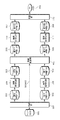
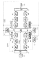
- FIG. 1 is a block diagram illustrating a functional configuration of the video / audio conversion apparatus according to the first embodiment.
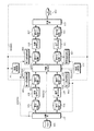
- FIG. 2 is a block diagram showing a functional configuration of the video / audio conversion apparatus according to the second embodiment.
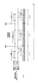
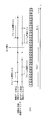
- FIG. 3 is a timing chart of the synchronization control in the second embodiment.
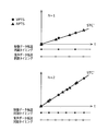
- FIG. 4 is a relationship diagram of the reference time STC ′, VPTS, and APTS at the synchronization timing in the second embodiment.
- FIG. 5 is a block diagram showing a functional configuration of the video / audio conversion apparatus according to the third embodiment.
- FIG. 6 is a timing diagram of delay control by stop and restart in the third embodiment.
- FIG. 7 is a timing diagram of delay control by N value adjustment in the third embodiment.
- FIG. 8 is a diagram showing a pattern in which audio data in the third embodiment is not supplied to the tenth intermediate buffer.
- FIG. 9 is a block diagram illustrating a functional configuration of the video / audio conversion device according to the fourth embodiment.
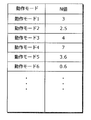
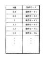
- FIG. 10 is a diagram showing a double speed information table according to the fourth embodiment.
- FIG. 11 is a block diagram illustrating a functional configuration of the video / audio conversion device according to the fifth embodiment.
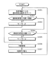
- FIG. 12 is a flowchart showing the operation of the double speed measurement control in the fifth embodiment.
- FIG. 13 is a block diagram illustrating a functional configuration of the video / audio conversion device according to the sixth embodiment.
- FIG. 14 is a flowchart showing the operation of the double speed determination control in the sixth embodiment.
- FIG. 15 is a block diagram illustrating a functional configuration of the video / audio conversion device according to the seventh embodiment.
- FIG. 16 is a timing chart of double speed switching control in the seventh embodiment.
- FIG. 17 is a flowchart showing the operation of double speed switching control in the seventh embodiment.
- FIG. 18 is a block diagram illustrating a functional configuration of the video / audio conversion device according to the eighth embodiment.
- FIG. 19 is a diagram showing a double speed information table according to the eighth embodiment.
- FIG. 1 is a block diagram showing a functional configuration of a video / audio conversion apparatus according to Embodiment 1 of the present invention.
- the HDD 001 and the DVD 002 are recording means, and the first multiplexed data compressed by, for example, MPEG of a television broadcast is recorded on the HDD 001.
- DVD002 is used for recording the second multiplexed data after rate conversion dubbing.
- the recording means may be a recording medium such as an HDD, a BD, or an SD card.
- the video / audio conversion apparatus includes a separation unit 101, a video decoding unit 102, an audio decoding unit 103, a video encoding unit 104, an audio encoding unit 105, and a multiplexing unit 106. Further, the separation unit 101 has a time information notification function (SIG 201) to the multiplexing unit 106, and the multiplexing unit 106 has a function of performing synchronization control of video data and audio data using the time information.
- SIG 201 time information notification function
- the demultiplexing unit 101 demultiplexes the first multiplexed data recorded in the HDD 001, and encodes the first encoded video data encoded by MPEG or the like and AC-3 (Audio Code number 3) or the like
- the first encoded audio data is stored in the first intermediate buffer 301, and the first encoded audio data is stored in the second intermediate buffer 302.
- the separation unit 101 also outputs output time information (PTS) and decoding time information (DTS), system time reference information (SCR), and program time reference for video data and audio data added to the first multiplexed data. Time information such as information (PCR) is notified to the multiplexing unit 106 (SIG201).
- the video decoding unit 102 performs a decoding process on the first encoded video data stored in the first intermediate buffer 301, and stores the decoded video data in the third intermediate buffer 303.
- the audio decoding unit 103 performs a decoding process on the first encoded audio data stored in the second intermediate buffer 302 and stores the decoded audio data in the fourth intermediate buffer 304.
- the video encoding unit 104 performs encoding processing of the video data stored in the third intermediate buffer 303 into compressed data such as MPEG, and stores the encoded second encoded video data in the fifth intermediate buffer 305. .
- the video encoding unit 104 may perform the encoding process after the video data decoded by the video decoding unit 102 is separately subjected to video processing such as high image quality or resolution conversion.
- the audio encoding unit 105 performs an encoding process on the audio data stored in the fourth intermediate buffer 304 into predetermined compressed data, and stores the encoded second encoded audio data in the sixth intermediate buffer 306. At this time, the speech encoding unit 105 may perform the encoding process after the speech data decoded by the speech decoding unit 103 is subjected to speech processing such as improving the sound quality separately.
- data is recompressed (rate conversion) at a compression rate different from the compression rate used when recording in the HDD001.
- rate conversion rate conversion
- a recompression method for example, there is a method described in the conventional example, and this method can also be applied.
- the multiplexing unit 106 uses the time information notified from the separation unit 101 to convert the second encoded video data stored in the fifth intermediate buffer 305 and the second encoded audio data stored in the sixth intermediate buffer 306.
- the second multiplexed data is generated by arranging the first encoded video data and the first encoded audio data in the first multiplexed data so that the relationship on the time axis is the same. After multiplexing while performing synchronization control of the second encoded video data and the second encoded audio data by this control, the second multiplexed data is recorded on the DVD002.
- the video / audio conversion device may recompress only one of the video data and the audio data.
- the demultiplexing unit 101 demultiplexes the first multiplexed data, and separates the first encoded video data encoded by MPEG or the like and the first encoded audio data encoded by AC-3 or the like.
- the first encoded video data is transferred to the first intermediate buffer 301.
- the video decoding unit 102 performs decoding
- the video encoding unit 104 performs encoding
- the fifth encoded buffer data 305 is transferred to the fifth intermediate buffer 305.
- the first encoded audio data is directly transferred to the sixth intermediate buffer 306 without being transferred to the second intermediate buffer 302.
- the multiplexing unit 106 multiplexes the second encoded video data stored in the fifth intermediate buffer 305 and the first encoded audio data stored in the sixth intermediate buffer 306, and stores the second multiplexed data in the DVD002. To record.
- the case of recompression of video data has been described, but the same processing is performed also in the case of recompression of only audio data.
- the separation unit 101, the video decoding unit 102, the audio decoding unit 103, the video encoding unit 104, the audio encoding unit 105, and the multiplexing unit 106 are each an intermediate buffer existing in the previous stage (the separation unit 101 has a buffer in the previous stage). Is not applicable because it does not exist) and the intermediate buffer existing in the subsequent stage (not applicable since there is no intermediate buffer in the subsequent stage in the multiplexing unit 106) is monitored.
- the separation unit 101, the video decoding unit 102, the audio decoding unit 103, the video encoding unit 104, the audio encoding unit 105, and the multiplexing unit 106 each have a remaining data amount in the intermediate buffer existing in the preceding stage If the amount of data is less than, the processing is stopped so that the underflow of the intermediate buffer does not occur. If the remaining data amount exceeds the predetermined threshold, the processing is resumed. In addition, when the remaining free space in the intermediate buffer existing in the subsequent stage falls below a predetermined threshold, the processing is stopped so that the overflow of the intermediate buffer does not occur, and when the remaining free space exceeds the predetermined threshold, Resume processing.
- the separation unit 101, the video decoding unit 102, the audio decoding unit 103, the video encoding unit 104, the audio encoding unit 105, and the multiplexing unit 106 can realize rate conversion dubbing at the optimum processing speed. . Further, by using the time information of the first multiplexed data, it is possible to generate second multiplexed data that enables accurate reproduction in which video and audio are synchronized.
- the essential components of the video / audio conversion device according to the present invention are the separation unit 101, the video decoding unit 102, the audio decoding unit 103, the video encoding unit 104, the audio encoding unit 105, The multiplexing unit 106 and other components may be provided outside the video / audio conversion device.
- FIG. 2 is a block diagram showing a functional configuration of the video / audio conversion apparatus according to Embodiment 2 of the present invention.
- the HDD 001 and the DVD 002 are recording means, and the first multiplexed data compressed by, for example, MPEG of a television broadcast is recorded in the HDD 001.
- DVD002 is used for recording the second multiplexed data after rate conversion dubbing.
- the recording means may be an SD card or the like.
- the video / audio conversion apparatus includes a separation unit 107, a video decoding unit 108, an audio decoding unit 109, a video encoding unit 110, an audio encoding unit 111, a multiplexing unit 112, and a synchronization unit.
- a thirteenth intermediate buffer 507 and a fourteenth intermediate buffer 508 are configured.
- the demultiplexing unit 107 demultiplexes the first multiplexed data recorded in the HDD 001, and the first encoded video data encoded by MPEG or the like and the first encoded data encoded by AC-3 or the like Separate into audio data.
- the video decoding unit 108 decodes the first encoded video data demultiplexed by the separation unit 107.
- the speech decoding unit 109 decodes the first encoded speech data demultiplexed by the separating unit 107.
- the video encoding unit 110 encodes the video data decoded by the video decoding unit 108.
- the speech encoding unit 111 encodes the speech data decoded by the speech decoding unit 109.
- the multiplexing unit 112 multiplexes the second encoded video data encoded by the video encoding unit 110 and the second encoded audio data encoded by the audio encoding unit 111, and the second multiplexed data Is generated.
- the synchronization control unit 401 determines the transfer timing of the video data decoded by the video decoding unit 108 to the video encoding unit 110 and the transfer of the audio data decoded by the audio decoding unit 109 to the audio encoding unit 111. adjust.
- the seventh intermediate buffer 501 temporarily stores the first encoded video data demultiplexed by the separation unit 107 when transferring it from the separation unit 107 to the video decoding unit 108.
- the eighth intermediate buffer 502 temporarily stores the first encoded speech data demultiplexed by the separation unit 107 when transferring it from the separation unit 107 to the speech decoding unit 109.
- the ninth intermediate buffer 503 temporarily stores the video data decoded by the video decoding unit 108 when the video data is transferred from the video decoding unit 108 to the synchronization control unit 401.
- the tenth intermediate buffer 504 temporarily stores the audio data decoded by the audio decoding unit 109 from the audio decoding unit 109 to the synchronization control unit 401.
- the eleventh intermediate buffer 505 temporarily stores the video data synchronously controlled by the synchronization control unit 401 when the video data is transferred from the synchronization control unit 401 to the video encoding unit 110.
- the twelfth intermediate buffer 506 temporarily stores the audio data synchronously controlled by the synchronization control unit 401 when it is transferred from the synchronization control unit 401 to the audio encoding unit 111.
- the thirteenth intermediate buffer 507 temporarily stores the second encoded video data encoded by the video encoding unit 110 when transferring it from the video encoding unit 110 to the multiplexing unit 112.
- the fourteenth intermediate buffer 508 temporarily stores the second encoded audio data encoded by the audio encoding unit 111 when transferring it from the audio encoding unit 111 to the multiplexing unit 112.
- the separation unit 107 has a function of notifying time information to the synchronization control unit 401 (SIG 402).
- SIG 402 synchronization control unit
- FIG. 3 shows the synchronization control timing in the synchronization control unit 401.
- the horizontal axis in FIG. 3 indicates the elapsed time t from the start of rate conversion dubbing.
- FIG. 4 is a diagram for explaining the synchronization control in the synchronization control unit 401.
- the horizontal axis in FIG. 4 indicates elapsed time t from the start of rate conversion dubbing, and the vertical axis indicates time information values.
- the synchronization control unit 401 obtains a value obtained by multiplying the system reference time STC (System Time Clock) by an N value (value of N) at the start of rate conversion dubbing, and first time information (time stamp, Subtract from SCR (System Clock Reference) or PCR (Program Clock Reference) etc. to obtain stc_base.
- the synchronization control unit 401 adds the STC ′ obtained by adding the value obtained by multiplying the STC by the N value to stc_base at the synchronization control timing of the video data transfer, and the time information notified from the separation unit 107.
- the video output time information (VPTS) relating to the output of the included video data is compared.
- the synchronization control unit 401 is decoded by the video decoding unit 108. Performs video data transfer control. If the value obtained by subtracting STC ′ from VPTS is greater than a predetermined threshold, the synchronization control unit 401 determines that the output time of the corresponding video data has not been reached, and the black data or the video data transferred at the previous synchronization control timing Perform transfer control.
- the synchronization control unit 401 determines that the output time of the corresponding video data has passed, and discards the corresponding video data without performing transfer. The next VPTS and STC 'are compared. The same control is performed when the VPTS is an invalid value due to missing or error of video data. If no new VPTS is notified from the separation unit 107 when there is no video data or when video data is missing, the synchronization control unit 401 transfers the black data or the video transferred at the previous synchronization control timing. Perform data transfer control. Expressions for obtaining stc_base and STC ′ are shown below.
- stc_base time information ⁇ STC ⁇ N Equation 1
- STC ′ stc_base + STC ⁇ N Equation 2
- the synchronization control unit 401 compares the STC ′ with the audio data output synchronization control timing and the audio output time information (APTS) regarding the output of the audio data included in the time information notified from the separation unit 107. If the value obtained by subtracting STC ′ from APTS is smaller than the predetermined threshold value, or the value obtained by subtracting APTS from STC ′ is smaller than the predetermined threshold value, the synchronization control unit 401 is decoded by the speech decoding unit 109. Performs audio data transfer control. When the value obtained by subtracting STC ′ from APTS is greater than a predetermined threshold, the synchronization control unit 401 determines that the output time of the corresponding audio data has not been reached, and performs transfer control of silent data.
- APTS audio output time information
- the synchronization control unit 401 determines that the output time of the corresponding audio data has passed, and discards the corresponding audio data without performing transfer. The next APTS and STC 'are compared. The same control is performed when the APTS is an invalid value due to missing audio data or an error. In addition, if no audio data exists or audio data is missing and the new APTS is not notified from the separation unit 107, the synchronization control unit 401 performs silence data transfer control.
- the video encoding unit 110 and the audio encoding unit 111 can perform encoding in a state where the video data and the audio data are synchronized.
- the multiplexing unit 112 encodes the second time encoded by the video encoding unit 110 and the audio encoding unit 111 with respect to the multiplexing time determined by the frame period of the video data and the audio data and the number of encoded frames. Since the encoded video data and the second encoded audio data may be multiplexed in a predetermined order, the synchronization control shown in the first embodiment is not necessary.
- the N of the double speed value of the rate conversion dubbing conversion speed will be described.
- the N value is determined by using the video / audio conversion apparatus shown in the second embodiment, with respect to synchronous control, the separation unit 107, the video decoding unit 108, the audio decoding unit 109, the video encoding unit 110, and the audio encoding unit 111. In addition, it is a value that can prevent the rate conversion dubbing from being performed without causing a delay in the multiplexing unit 112.
- the formula for calculating the N value is shown below.
- S1 S1min ⁇ S1 ⁇ S1max: the throughput factor of the separation unit 107
- S2 S2min ⁇ S2 ⁇ S2max: the magnification factor of the video decoding unit 108
- S3 S3min ⁇ S3 ⁇ S3max
- S4 S4min.ltoreq.S4.ltoreq.S4max
- S5 S5min.ltoreq.S5.ltoreq.S5max
- S6 S6min.ltoreq.S6.ltoreq.S6max: Multiplexing unit 112. Throughput rate
- the function min () for calculating N is a function for obtaining the minimum value from the arguments.
- Each argument indicates the throughput magnification of the separation unit 107, the video decoding unit 108, the audio decoding unit 109, the video encoding unit 110, the audio encoding unit 111, or the multiplexing unit 112.
- Simax (i is the number of each block).
- N is 2.4.
- the separation unit 107, the video decoding unit 108, the audio decoding unit 109, the video encoding unit 110, the audio encoding unit 111, and the multiplexing unit 112 are not delayed with respect to the synchronization control. Rate conversion dubbing can be performed.
- the video decoding unit 108 stops the decoding in the video decoding unit 108 based on the progress of the synchronization control in the synchronization control unit 401 as the progress of the encoding in the video encoding unit 110.
- the restart may be controlled.
- the speech decoding unit 109 stops and restarts the decoding in the speech decoding unit 109 based on the progress of synchronization control in the synchronization control unit 401 as the progress of encoding in the speech encoding unit 111. You may control.
- the video encoding unit 110 encodes the video data synchronized by the synchronization control unit 401 as the encoding of the video data generated by the video decoding unit 108, and the decoding progress of the video decoding unit 108 As an alternative, the stop and restart of encoding may be controlled based on the progress of synchronization control in the synchronization control unit 401.
- the speech encoding unit 111 encodes the speech data synchronized by the synchronization control unit 401 as the speech data generated by the speech decoding unit 109, and the progress of decoding by the speech decoding unit 109 As an alternative, the stop and restart of encoding may be controlled based on the progress of synchronization control in the synchronization control unit 401.
- the separation unit 107, the video decoding unit 108, the audio decoding unit 109, the video encoding unit 110, the audio encoding unit 111, and the multiplexing unit 112 are each an intermediate buffer existing in the preceding stage (the separating unit 107 includes Therefore, the data storage state of the intermediate buffer (not applicable since the buffer does not exist in the multiplexing unit 112 is not applicable) is monitored.
- the separation unit 107, the video decoding unit 108, the audio decoding unit 109, the video encoding unit 110, the audio encoding unit 111, and the multiplexing unit 112 each have a data remaining amount in the intermediate buffer existing in the preceding stage as a predetermined threshold value.
- each intermediate buffer according to the difference between the processing speed of the synchronization control and the processing speed of the separation unit 107, the video decoding unit 108, the audio decoding unit 109, the video encoding unit 110, the audio encoding unit 111, and the multiplexing unit 112. Overflow or underflow can be avoided.
- FIG. 5 is a block diagram showing a functional configuration of the video / audio conversion apparatus according to the third embodiment.
- the video / audio conversion device in the third embodiment includes a double speed notification unit 1201, a delay control unit 701, a first delay detection unit 801, A second delay detection unit 802, a third delay detection unit 803, and a fourth delay detection unit 804 are provided.
- the double speed notification unit 1201 notifies the synchronization control unit 401 of the double speed value of the conversion speed of rate conversion dubbing.
- the delay control unit 701 sends a delay control notification (SIG 702) to the synchronization control unit 401.
- SIG 702 a delay control notification
- the first delay detection unit 801 detects a decoding delay in the video decoding unit 108.
- the second delay detection unit 802 detects a decoding delay in the audio decoding unit 109.
- the third delay detection unit 803 detects the encoding delay in the video encoding unit 110.
- the fourth delay detection unit 804 detects the encoding delay in the speech encoding unit 111.
- the separation unit 107 has a function of stopping the first delay detection unit 801, the second delay detection unit 802, the third delay detection unit 803, and the fourth delay detection unit 804 when the first multiplexed data is abnormal. .
- each block and the flow of signals will be described.
- the double speed notification unit 1201 notifies the synchronization control unit 401 of an N value (for example, N + 1) exceeding the N value obtained by Equation 3 of Embodiment 2 at the start of rate conversion dubbing (SIG 1202).
- the synchronization control unit 401 uses the N value from the double speed notification unit 1201 as the synchronization control timing and the calculated value of the STC ′.
- the first delay detection unit 801 detects a decoding delay in the video decoding unit 108 with respect to the synchronization control.
- the second delay detection unit 802 detects a decoding delay in the audio decoding unit 109 with respect to the synchronization control.
- the third delay detection unit 803 detects a coding delay in the video coding unit 110 with respect to the synchronization control.
- the fourth delay detection unit 804 detects the encoding delay in the audio encoding unit 111 with respect to the synchronization control.
- the first delay detector 801, the second delay detector 802, the third delay detector 803, and the fourth delay detector 804 notify the delay controller 701 of a delay when a delay is detected.
- the delay control unit 701 When the delay control unit 701 receives a delay notification from any of the first delay detection unit 801, the second delay detection unit 802, the third delay detection unit 803, and the fourth delay detection unit 804, the delay control unit 701 performs synchronous control as a delay control notification.
- the unit 401 is notified of the stop of synchronization control.
- the block that made the delay notification among the first delay detection unit 801, the second delay detection unit 802, the third delay detection unit 803, and the fourth delay detection unit 804 A restart notification is sent to the control unit 701.
- the delay control unit 701 When the delay control unit 701 receives the restart notification, the delay control unit 701 sends a synchronization control restart notification to the synchronization control unit 401 as a delay control notification (the above control is referred to as delay control).
- delay control the delay control
- the horizontal axis in FIG. 6 indicates the elapsed time t from the start of rate conversion dubbing.
- the delay control unit 701 issues a restart notification to the delay control unit 701 and receives the delay restart notification
- the delay control unit 701 issues a restart notification to the synchronization control unit 401.
- the synchronization control unit 401 restarts the synchronization control while maintaining the video data transfer timing and the audio data transfer timing before stopping.
- STC′_diff STC′_diff + (preSTC ⁇ pastSTC) (Formula 4)
- STC ′ stc_base + STC ⁇ N ⁇ STC′_diff Equation 5
- the synchronization control can be resumed without disturbing the transfer timing of the video data and the transfer timing of the audio data even after the delay control.
- the delay control unit 701 is configured such that when the delay notification and the restart notification from the first delay detection unit 801, the second delay detection unit 802, the third delay detection unit 803, and the fourth delay detection unit 804 overlap, This can be dealt with by providing a flag corresponding to the delay detection unit.
- the delay control unit 701 sets a flag by a delay notification from each delay detection unit, drops a flag by a restart notification, and performs control to resume synchronous control when all the flags are dropped.
- the first delay detection unit 801, the second delay detection unit 802, the third delay detection unit 803, and the like are performed by performing control to restart the synchronization control when the same number of restart notifications are received for a plurality of delay notifications. Even when the delay notification and the restart notification from the fourth delay detection unit 804 overlap, control with consistency can be performed.
- the delay control method may be performed by adjusting the N value, which is a double speed value of rate conversion dubbing, instead of stop / restart control of synchronous control.
- FIG. 7 is a diagram showing a delay control method by adjusting the N value.
- the horizontal axis in FIG. 7 indicates the elapsed time t from the start of rate conversion dubbing.
- the delay control unit 701 When the delay control unit 701 receives a delay notification from one of the delay detection units, the delay control unit 701 notifies the synchronization control unit 401 of the N value (2 ⁇ 1). Upon receiving the N value from the delay control unit 701, the synchronization control unit 401 obtains a value obtained by multiplying the system reference time STC by the N value, and subtracts it from STC ′ to correct stc_base. Also, the synchronization control unit 401 performs synchronization control by switching between the timing of synchronization control (frame period ⁇ 1/2 ⁇ frame period ⁇ 1/1) and the STC ′ count-up value (2 ⁇ 1).
- the delay detection unit that has issued the delay notification issues a restart notification to the delay control unit 701.
- the delay control unit 701 notifies the synchronization control unit 401 of the N value (1 ⁇ 2).
- the synchronization control unit 401 obtains a value obtained by multiplying the system reference time STC by the N value, and subtracts it from STC ′ to correct stc_base.
- the synchronization control unit 401 performs synchronization control by switching between synchronization control timing (frame period ⁇ 1/1 ⁇ frame period ⁇ 1/2) and STC ′ count-up value (1 ⁇ 2).
- the calculation formula of stc_base at the time of correction is shown below.
- Stc_base STC'-STC ⁇ N ... Equation 6
- first delay detection unit 801, the second delay detection unit 802, the third delay detection unit 803, and the fourth delay detection unit 804 will be described.
- the first delay detection unit 801 monitors the data amount in the ninth intermediate buffer 503 in order to detect the decoding delay in the video decoding unit 108.
- the first delay detection unit 801 temporarily stops synchronization control.
- the delay notification to the delay control unit 701 is performed. Since the synchronization control is stopped by the delay control of the delay control unit 701, the data in the first intermediate buffer 301 is not consumed, so that the data amount is increased by the decoding by the video decoding unit.
- the first delay detection unit 801 notifies the delay control unit 701 to restart in order to restart the synchronization control. Accordingly, it is possible to prevent occurrence of underflow in the ninth intermediate buffer 503 due to a delay in processing of the video decoding unit 108.
- the third delay detection unit 803 monitors the amount of data in the eleventh intermediate buffer 505 in order to detect the encoding delay in the video encoding unit 110. If the encoding in the video encoding unit 110 is delayed and the amount of data in the eleventh intermediate buffer 505 exceeds the delay determination threshold, the third delay detection unit 803 temporarily stops the synchronization control. Therefore, a delay notification is sent to the delay control unit 701. Since the synchronization control is stopped by the delay control of the delay control unit 701, the video data is not supplied to the eleventh intermediate buffer 505. Therefore, the data amount is reduced by the encoding by the video encoding unit 110.
- the third delay detection unit 803 notifies the delay control unit 701 to restart in order to restart the synchronization control. Accordingly, it is possible to prevent the eleventh intermediate buffer 505 from overflowing due to the delay in encoding in the video encoding unit 110.
- the delay detection method may monitor the number of frames stored in the intermediate buffer instead of monitoring the data amount of the intermediate buffer.
- the decoding delay in the video decoding unit 108 and the encoding delay in the video encoding unit 110 have been described.
- the decoding in the audio decoding unit 109 and the encoding delay in the audio encoding unit 111 are described.
- the second delay detection unit 802 and the fourth delay detection unit 804 the same processing is performed.
- the first delay detection unit 801 monitors the number of frames of video data generated by the video decoding unit 108 and the number of frames of video data subjected to synchronization control by the synchronization control unit 401 so that the video decoding unit 108 The decoding delay may be detected.
- the second delay detection unit 802 monitors the number of frames of the voice data generated by the voice decoding unit 109 and the number of frames of the voice data subjected to synchronization control by the synchronization control unit 401, thereby decoding in the voice decoding unit 109. A delay in the conversion may be detected.
- the third delay detection unit 803 monitors the number of frames of video data for which synchronization control is performed by the synchronization control unit 401 and the number of frames of second encoded video data generated by the video encoding unit 110, thereby monitoring the video encoding unit.
- a coding delay at 110 may be detected.
- the fourth delay detection unit 804 monitors the number of frames of audio data for which the synchronization control unit 401 has performed synchronization control and the number of frames of second encoded audio data generated by the audio encoding unit 111 to thereby detect the audio encoding unit.
- a coding delay at 111 may be detected.
- FIG. 8 is a diagram showing a pattern when audio data is not supplied to the tenth intermediate buffer 504. The delay control in each pattern will be described.
- the separation unit 107 determines that the first encoded audio data does not exist by analyzing information such as an MPEG system header, for example. If it is determined by this determination that the first encoded audio data does not exist in the first multiplexed data, the separation unit 107 stops the second delay detection unit 802 and the fourth delay detection unit 804 (SIG 703). By this abnormal control, the synchronization control is not stopped even when data is not supplied to the tenth intermediate buffer 504 due to the first multiplexed data in which no sound exists.
- Separating section 107 determines a period in which no first encoded audio data exists for STC ′ from time information such as SCR or PCR and audio output time information. If it is determined by this determination that the first encoded audio data does not exist in the first multiplexed data, the separation unit 107 stops the second delay detection unit 802 and the fourth delay detection unit 804. Due to this abnormal control, the synchronization control stops even when data is not supplied to the tenth intermediate buffer 504 because the first encoded audio data is missing or the first encoded audio data does not exist for an indefinite period. Will disappear.
- the abnormal system control is not necessary and the normal system delay control may be performed.
- synchronization control is performed with an N value larger than the N value in the second embodiment, and the separation unit 107 and the video decoding unit 108 for the synchronization control are performed.
- the delay of the audio decoding unit 109, the video encoding unit 110, the audio encoding unit 111, and the multiplexing unit 112 is controlled so as not to disturb the synchronization of the video data and the audio data. It is possible to realize rate conversion dubbing faster than 2. Also, when the processing performance of each block is increased, the rate conversion dubbing performance can be improved without changing this configuration by simply changing the N value.
- FIG. 9 is a block diagram illustrating a functional configuration of the video / audio conversion device according to the fourth embodiment.
- the video / audio conversion device includes an operation mode determination unit 1401 in addition to the configuration of the video / audio conversion device according to the third embodiment shown in FIG.
- an operation mode determination unit 1401 in addition to the configuration of the video / audio conversion device according to the third embodiment shown in FIG.
- each block and signal flow will be described.
- the operation mode determination unit 1401 performs demultiplexing by the separation unit 107 during rate conversion dubbing, decoding by the video decoding unit 108, decoding by the audio decoding unit 109, encoding by the video encoding unit 110, and audio
- Each element that affects the encoding in the encoding unit 111 or the multiplexing in the multiplexing unit 112 for example, the resolution of the video data in the first multiplexed data, the resolution of the video data in the second multiplexed data, the first Bit rate of multiplexed data, bit rate of second multiplexed data, frame rate of video data in first multiplexed data, frame rate of video data in second multiplexed data, first multiplexed data Audio data sampling frequency, second multiplexed data audio data sampling frequency, first multiplexed data video data codec, Codec of video data in multiplexed data, codec of audio data in first multiplexed data, codec of audio data in second multiplexed data, number of channels of audio data in first multiplex
- the operation modes are defined as operation modes 1, 2, 3,... According to combinations of elements such as resolution and bit rate.
- the operation mode determination unit 1401 selects an optimum N value for each operation mode from the double speed information table shown in FIG. 10, and notifies the double speed notification unit 1201 (SIG1402).
- the double speed notification unit 1201 that has received the N value notifies the synchronization control unit 401 of the N value.
- the N value at which the separation unit 107, the video decoding unit 108, the audio decoding unit 109, the video encoding unit 110, the audio encoding unit 111, and the multiplexing unit 112 operate optimally is selected for each operation mode.
- optimum rate conversion dubbing can be performed.
- the N value operates at a double speed less than 1, many processes are performed in the separation unit 107, the video decoding unit 108, the audio decoding unit 109, the video encoding unit 110, the audio encoding unit 111, and the multiplexing unit 112.
- the video decoding unit 108, the audio decoding unit 109, the video encoding unit 110, and the audio encoding unit 111 can devote time to high image quality and high quality audio processing, High-quality second multiplexed data can be generated.
- the double speed notification unit 1201 may select N to be notified by an external instruction. Good.
- FIG. 11 is a block diagram illustrating a functional configuration of the video / audio conversion device according to the fifth embodiment.
- the video / audio conversion apparatus includes a double speed measurement unit 1501 in addition to the configuration of the video / audio conversion apparatus according to the third embodiment shown in FIG.
- the delay control unit 701 has a function of notifying the double speed measurement unit 1501 of delay occurrence information (SIG 1503).
- SIG 1503 delay occurrence information
- Embodiment 5 describes a method for selecting an N value by measuring the N value before starting rate conversion dubbing, as a method for selecting an N value for rate conversion dubbing different from that in Embodiment 4.
- FIG. 12 is a flowchart for explaining a double speed measurement method for measuring the N value before starting the rate conversion dubbing.
- the double speed measurement unit 1501 obtains the N value obtained by the equation 3.
- the double speed measurement unit 1501 saves the N value used when the N value for rate conversion dubbing is determined as N 'in a buffer (not shown).
- the double speed measurement unit 1501 adds the predetermined value ⁇ to the N value to obtain the N value used in the rate conversion dubbing.
- rate conversion dubbing for a predetermined period is executed, and the double speed measurement unit 1501 receives delay generation information (SIG 1502) from the delay control unit 701, and counts the number of occurrences of delay control.
- SIG 1502 delay generation information
- the double speed measurement unit 1501 determines the number of occurrences of delay control and a predetermined threshold value. Here, if the number of occurrences of delay control exceeds the threshold value, the process proceeds to S106, and if it is lower, the process returns to S102, and the N value is saved as N 'in a buffer (not shown) and rate conversion dubbing is performed again.
- the double speed measurement unit 1501 determines the N value to be used in the actual rate conversion dubbing notified to the double speed notification unit 1201 by substituting the value of N ′ saved in the buffer in S102 into the N value. To do.
- the separation unit 107, the video decoding unit 108, the audio decoding unit 109, the video encoding unit 110, the audio encoding unit 111, and the multiplexing unit can be performed without determining an optimal N value for each operation mode in advance.
- Rate conversion dubbing can be performed with an N value at which 112 operates optimally.
- the value of ⁇ may be a value unique to the device or may be given from the outside.
- FIG. 13 is a block diagram illustrating a functional configuration of the video / audio conversion device according to the sixth embodiment.
- the video / audio conversion apparatus includes a second operation mode determination unit 1601, a second double speed measurement unit 1602, and a double speed recording memory 1603 in addition to the configuration of the video / audio conversion apparatus according to the third embodiment shown in FIG. Prepare.
- a second operation mode determination unit 1601 a second double speed measurement unit 1602
- a double speed recording memory 1603 in addition to the configuration of the video / audio conversion apparatus according to the third embodiment shown in FIG. Prepare.
- each block and the flow of signals will be described.
- the second operation mode determination unit 1601 performs demultiplexing in the demultiplexing unit 107, decoding in the video decoding unit 108, decoding in the audio decoding unit 109, encoding in the video encoding unit 110, and audio encoding.
- the operation mode is determined according to the operation setting that affects the encoding in the unit 111 or the multiplexing in the multiplexing unit 112. As described above, the operation modes are defined as operation modes 1, 2, 3,... According to combinations of elements such as resolution and bit rate.
- the second double speed measurement unit 1602 measures the N before starting rate conversion dubbing.
- the double speed recording memory 1603 records the measured N.
- the second operation mode determination unit 1601 notifies the recorded N to the double-speed notification unit 1201 (SIG1604), and enters the operation mode.
- the second double speed measurement unit 1602 is notified of activation (SIG 1605).
- the second double speed measurement unit 1602 measures the optimum N for each operation mode, records the N for each operation mode on the double speed recording memory 1603 (SIG1607), and notifies the double speed notification unit 1201 of the N ( SIG1606).
- FIG. 14 is a flowchart for explaining a double speed determination method for measuring the N value before starting the rate conversion dubbing.
- the second operation mode determination unit 1601 determines each element (for example, video data resolution in the first multiplexed data, video data resolution in the second multiplexed data, Bit rate of first multiplexed data, bit rate of second multiplexed data, frame rate of video data in first multiplexed data, frame rate of video data in second multiplexed data, first multiplexing Audio data sampling frequency in the multiplexed data, audio data sampling frequency in the second multiplexed data, video data codec in the first multiplexed data, video data codec in the second multiplexed data, first multiplexing Codec for audio data in coded data, codec for audio data in second multiplexed data, All the elements such as the number of audio data channels in the multiplexed data, the number of audio data channels in the second multiplexed data, the multiplexed format of the first multiplexed data, or the multiplexed format of the second multiplexed data Pointed without omission) and determine the operation mode.
- each element for example, video
- the second operation mode determination unit 1601 determines whether the N value of the operation mode is recorded in the double speed recording memory 1603. If the N value is recorded, the process proceeds to S203, and if not recorded, the process proceeds to S204.
- the second operation mode determination unit 1601 selects an optimum N value for each operation mode from the double speed recording memory 1603, and notifies the N value to the double speed notification unit 1201 (SIG1604), thereby using the rate conversion dubbing. N value to be determined is determined.
- the second operation mode determination unit 1601 notifies the second double speed measurement unit 1602 of activation (SIG1605).
- the second double speed measurement unit 1602 obtains the N value obtained by the equation 3.
- the second double speed measurement unit 1602 saves the N value used when the N value for rate conversion dubbing is determined as N 'in a buffer (not shown).
- the second double speed measurement unit 1602 obtains an N value to be used for rate conversion dubbing by adding a predetermined value ⁇ to the N value.
- rate conversion dubbing for a predetermined period is executed, and the second double speed measurement unit 1602 receives delay generation information (SIG1502) from the delay control unit 701 and counts the number of occurrences of delay control.
- the second double speed measurement unit 1602 determines the number of occurrences of delay control and a predetermined threshold value.
- the process proceeds to S210, and if it is lower, the process returns to S206.
- the N value is saved as N 'in a buffer (not shown) and the rate conversion dubbing is performed again.
- the second double speed measurement unit 1602 substitutes the value of N ′ saved in the buffer in S206 for the N value.
- the second double speed measurement unit 1602 records the N value in the double speed recording memory 1603 (SIG1607).
- the second double speed measurement unit 1602 notifies the N value to the double speed notification unit 1201 (SIG1606), thereby determining the N value used in the rate conversion dubbing.
- the separation unit 107, the video decoding unit 108, the audio decoding unit 109, the video encoding unit 110, the audio encoding unit 111, and the multiplexing unit can be performed without determining an optimal N value for each operation mode in advance.
- Rate conversion dubbing can be performed with an N value at which 112 operates optimally. Further, when operating in the same operation mode, it is possible to shorten the time until rate conversion dubbing is started as compared with the fifth embodiment.
- the value of ⁇ As described above, when a small value is given, the accuracy of the optimum N value is improved, but it takes time to reach the optimum value. If a large value is given, the time to reach the optimum value is shortened, but the accuracy of the optimum N value is lowered.
- the value of ⁇ may be a value unique to the device or may be given from the outside.
- FIG. 15 is a block diagram illustrating a functional configuration of the video / audio conversion device according to the seventh embodiment.
- the video / audio conversion device includes a third operation mode determination unit 1801 and a third double speed measurement unit 1802 in addition to the configuration of the video / audio conversion device according to the third embodiment shown in FIG.
- a third operation mode determination unit 1801 and a third double speed measurement unit 1802 in addition to the configuration of the video / audio conversion device according to the third embodiment shown in FIG.
- each block and the flow of signals will be described.
- the double speed notification unit 1201 switches the N to be notified to the synchronization control unit 401 during rate conversion dubbing.
- the N value used in the synchronization control is not an optimal value, so the rate conversion dubbing speed may be reduced.
- an operation of switching to an optimal N value when the operation mode is switched during rate conversion dubbing will be described.
- FIG. 16 is a diagram showing N value switching.
- the horizontal axis in FIG. 16 indicates the elapsed time t from the start of rate conversion dubbing.
- the third operation mode determination unit 1801 monitors operation mode switching during rate conversion dubbing. When the operation mode is switched, the third operation mode determination unit 1801 selects an optimum N value for each operation mode and notifies the double speed notification unit 1201 (SIG1803). Receiving the N value, the double speed notification unit 1201 notifies the synchronization control unit 401 of the N value (2 ⁇ 1). The synchronization control unit 401 that has received the N value from the double speed notification unit 1201 obtains a new stc_base according to Equation 6 above. In addition, the synchronization control unit 401 performs synchronization control by switching the timing (frame period ⁇ 1/2 ⁇ frame period ⁇ 1/1) of the synchronization control unit 401 and the STC ′ count-up value (2 ⁇ 1).
- the above control makes it possible to switch the N value during rate conversion dubbing.
- FIG. 17 is a flowchart for explaining control for measuring an optimum N value during rate conversion dubbing.
- the third double speed measuring unit 1802 counts the number of delay occurrences during a predetermined period during rate conversion dubbing.
- the third double speed measurement unit 1802 determines the number of occurrences of delay control and a predetermined threshold value. Here, if the number of occurrences of delay control exceeds the threshold value, the process proceeds to S303, and if it is less than the threshold value, the process proceeds to S304.
- the third double speed measurement unit 1802 obtains an N value to be used for rate conversion dubbing by subtracting a predetermined value ⁇ from the N value.
- the third double speed measurement unit 1802 determines whether delay control has occurred. Here, if delay control has not occurred, the process proceeds to S305, and if it has occurred, the process returns to S301 to again count the number of occurrences of delay in a predetermined period.
- the third double speed measurement unit 1802 obtains an N value to be used for rate conversion dubbing by adding a predetermined value ⁇ to the N value.
- the third double speed measurement unit 1802 notifies the N value to the double speed notification unit 1201 (SIG1804).
- the double speed notification unit 1201 controls switching to the N value.
- the rate conversion dubbing can be performed with the N value that operates optimally.
- the values of ⁇ and ⁇ if a small value is given, the accuracy of the optimum N value is improved, but it takes time to reach the optimum value. If a large value is given, the time to reach the optimum value is shortened, but the accuracy of the optimum N value is lowered. Note that the values of ⁇ and ⁇ may be values inherent to the device or may be given from the outside.
- FIG. 18 is a block diagram illustrating a functional configuration of the video / audio conversion device according to the eighth embodiment.
- the video / audio conversion device includes a double speed determination unit 1901 and a double speed notification unit 1905 in addition to the configuration of the video / audio conversion device according to the second embodiment shown in FIG.
- a double speed determination unit 1901 and a double speed notification unit 1905 in addition to the configuration of the video / audio conversion device according to the second embodiment shown in FIG.
- each block and the flow of signals will be described.
- the double speed determination unit 1901 receives the N value from the double speed notification unit 1905 at the start of rate conversion dubbing (SIG1902), and sets the operation mode so that rate conversion dubbing with the N value can be realized (SIG1903). For example, as in the double speed information table shown in FIG.
- an operation mode is selected for each N value, and each element that affects the operation during rate conversion dubbing (for example, the resolution of the video data in the second multiplexed data, the first Bit rate of double multiplexed data, frame rate of video data in second multiplexed data, sampling frequency of audio data in second multiplexed data, codec of video data in second multiplexed data, second multiple All of the codec of audio data in multiplexed data, the number of channels of audio data in the first multiplexed data, the number of channels of audio data in the second multiplexed data, or the multiplexing format of the second multiplexed data, etc. Point to the element without omission).
- each element that affects the operation during rate conversion dubbing for example, the resolution of the video data in the second multiplexed data, the first Bit rate of double multiplexed data, frame rate of video data in second multiplexed data, sampling frequency of audio data in second multiplexed data, codec of video data in second multiplexed data, second multiple All
- the separation unit 107, the video decoding unit 108, the audio decoding unit 109, and the video encoding are performed in the operation mode corresponding to the closest N value on the table.
- Unit 110, speech encoding unit 111, and multiplexing unit 112 are set, and N value is notified to double speed notification unit 1905 (SIG1904).
- the double speed notification unit 1905 notifies the synchronization control unit 401 of the N value received from the double speed determination unit 1901 (SIG 1906).
- the selection of the priority of the separation unit 107, the video decoding unit 108, the audio decoding unit 109, the video encoding unit 110, the audio encoding unit 111, and the multiplexing unit 112 or the presence / absence of mode change is added to the operation mode options. May be.
- This configuration makes it possible to generate high-quality second multiplexed data for rate conversion dubbing at a predetermined magnification.
- Each device described above may be realized by hardware.
- each of the above devices may be specifically configured as a computer system including a microprocessor, ROM, RAM, hard disk drive, display unit, keyboard, mouse, and the like.
- a computer program is stored in the RAM or hard disk drive.
- Each device achieves its functions by the microprocessor operating according to the computer program.
- the computer program is configured by combining a plurality of instruction codes indicating instructions for the computer in order to achieve a predetermined function.
- the system LSI is a super multifunctional LSI manufactured by integrating a plurality of components on a single chip, and specifically, a computer system including a microprocessor, a ROM, a RAM, and the like. . A computer program is stored in the RAM. The system LSI achieves its functions by the microprocessor operating according to the computer program.
- each of the above-described devices may be configured from an IC card or a single module that can be attached to and detached from each device.
- the IC card or module is a computer system that includes a microprocessor, ROM, RAM, and the like.
- the IC card or the module may include the super multifunctional LSI described above.
- the IC card or the module achieves its function by the microprocessor operating according to the computer program. This IC card or this module may have tamper resistance.
- the present invention may be the method described above. Further, the present invention may be a computer program that realizes these methods by a computer, or may be a digital signal composed of the computer program.
- the present invention provides a non-volatile recording medium that can read the computer program or the digital signal, such as a flexible disk, a hard disk, a CD-ROM, an MO, a DVD, a DVD-ROM, a DVD-RAM, a BD (Blu-ray). -ray Disc (registered trademark)), recorded on a semiconductor memory, or the like.
- the digital signal may be recorded on these non-volatile recording media.
- the computer program or the digital signal may be transmitted via an electric communication line, a wireless or wired communication line, a network represented by the Internet, data broadcasting, or the like.
- the present invention may also be a computer system including a microprocessor and a memory.
- the memory may store the computer program, and the microprocessor may operate according to the computer program.
- the video / audio conversion apparatus and method according to the present invention are useful for a video / audio conversion apparatus and method for performing high-speed rate conversion dubbing.
Landscapes
- Engineering & Computer Science (AREA)
- Signal Processing (AREA)
- Multimedia (AREA)
- Compression Or Coding Systems Of Tv Signals (AREA)
- Two-Way Televisions, Distribution Of Moving Picture Or The Like (AREA)
- Television Signal Processing For Recording (AREA)
Abstract
レート変換ダビング時に、分離部(101)、映像復号化部(102)、音声復号化部(103)、映像符号化部(104)、音声符号化部(105)および多重部(106)が高い効率で並列に動作することで、処理時間を短縮する。分離部(101)、映像復号化部(102)、音声復号化部(103)、映像符号化部(104)、音声符号化部(105)および多重部(106)は、前段と後段の処理部の処理状態を監視しながら、処理の停止および再開の制御を行うことにより、各処理部を最善な処理速度で動作させることができ、レート変換ダビングの処理時間を短くすることができる。
Description
本発明は、第一符号化映像データおよび第一符号化音声データが多重化された第一多重化データを入力として受け、高速にレート変換ダビングを行う映像音声変換装置とその方法に関するものである。
従来のHDD(Hard Disk Drive)/DVD(Digital Versatile Disc)レコーダなどの一般的な記録再生を行う記録再生装置において、HDDに記録しているDVDの記録容量より大きなサイズの映像音声データを、DVDに収まるサイズに変換するレート変換を行い、DVDに記録するレート変換ダビング機能を有しているものが存在する。
一般的にレート変換ダビングは、HDD等に記録しているMPEG(Moving Picture Experts Group)等で圧縮された映像音声データの復号化を行い、復号化した映像音声データの表示制御を行いながら復号化した映像音声データの符号化を行い、DVD等に記録することで実現する。
しかしながら、上記制御では、復号化および符号化は、テレビの出力に同期してレート変換ダビングを行うこととなるため、表示時間と同じだけのダビング時間が必要となっていた。
これを解決し、高速なレート変換ダビングを実現する方法として、例えば、特許文献1に記載されている映像音声データに関するレート変換ダビング方法がある。
上記特許文献1に記載されているレート変換ダビングでは、まず、映像音声復号化部において所定の単位の映像音声データの復号化を開始する。復号化が完了すると映像音声復号化部から映像音声符号化部へ復号化完了通知が送られる。この完了通知を受信した映像音声符号化部では、直ちに復号化された映像音声データの符号化を開始する(符復号化の処理では、変換前の圧縮率より高い圧縮率で映像音声データの再圧縮を行う)。符号化が完了すると映像音声符号化部から映像音声復号化部へ符号化完了通知が送られる。この完了通知を受信した映像音声復号化部では、直ちに次の映像音声データの復号化を開始する。このような制御を行うことにより、映像音声復号化部および映像音声符号化部の処理は、テレビの出力に同期する必要がなくなるため、レート変換ダビングの処理時間を短縮することができる。
しかしながら、上記の特許文献1に記載されているレート変換技術では、逐次処理により映像音声復号化部と映像音声符号化部を切り替えながらレート変換ダビングを行う。これにより、映像音声復号化部および映像音声符号化部では、それぞれ停止期間が生じるため、処理の効率が低く、レート変換ダビングの処理時間は長くなってしまう。
本発明は、上記課題を解決するために、映像音声データに関するレート変換ダビング時に、映像音声復号化部および映像音声符号化部が高い効率で並列に動作することで、処理時間を短縮できる映像音声変換装置および方法を提供することを目的とする。
上記目的を達成するために、本発明のある局面に係る映像音声変換装置は、第一符号化映像データおよび第一符号化音声データが多重化された第一多重化データから、第二符号化映像データおよび第二符号化音声データが多重化された第二多重化データを生成する映像音声変換装置であって、第一多重化データから第一符号化映像データと第一符号化音声データを多重分離する分離部と、前記分離部で多重分離された第一符号化映像データを復号化することにより、映像データを生成する映像復号化部と、前記分離部で多重分離された第一符号化音声データを復号化することにより、音声データを生成する音声復号化部と、前記映像復号化部で生成された映像データを符号化することにより、第二符号化映像データを生成する映像符号化部と、前記音声復号化部で生成された音声データを符号化することにより、第二符号化音声データを生成する音声符号化部と、前記映像符号化部で生成された第二符号化映像データと前記音声符号化部で生成された第二符号化音声データの多重化を行うことにより、第二多重化データを生成する多重部とを備え、前記分離部は、前記映像復号化部および前記音声復号化部での復号化の進行状況に基づいて、前記分離部での多重分離の停止および再開を制御し、前記映像復号化部は、前記分離部での多重分離の進行状況および前記映像符号化部での符号化の進行状況に基づいて、前記映像復号化部での復号化の停止および再開を制御し、前記音声復号化部は、前記分離部での多重分離の進行状況および前記音声符号化部での符号化の進行状況に基づいて、前記音声復号化部での復号化の停止および再開を制御し、前記映像符号化部は、前記映像復号化部での復号化の進行状況および前記多重部での多重化の進行状況に基づいて、前記映像符号化部での符号化の停止および再開を制御し、前記音声符号化部は、前記音声復号化部での復号化の進行状況および前記多重部での多重化の進行状況に基づいて、前記音声符号化部での符号化の停止および再開を制御し、前記多重部は、前記映像符号化部および前記音声符号化部での符号化の進行状況に基づいて、前記多重部での多重化の停止および再開を制御する。
この構成によると、分離部、映像復号化部、音声復号化部、映像符号化部、音声符号化部および多重部の処理速度の差を吸収するために、各処理部は、前後の処理部における処理の進行状況に基づいて、自身の処理の停止および再開を制御している。これにより、分離部、映像復号化部、音声復号化部、映像符号化部、音声符号化部および多重部が最善な処理速度で動作することで高速なレート変換ダビングを行うことができる。
また、前記分離部は、さらに、前記第一多重化データに付加されている時刻情報を、前記多重部に通知し、前記多重部は、前記分離部より通知された前記時刻情報を用いて、第二符号化映像データと第二符号化音声データの多重化を行い、前記第二多重化データを生成してもよい。
また、前記分離部は、前記分離部が多重分離した第一符号化映像データを前記分離部から前記映像復号化部へ転送する際に一時的に格納する第一中間バッファのデータ蓄積状態を監視することにより前記映像復号化部での復号化の進行状況を判断し、前記分離部が多重分離した第一符号化音声データを前記分離部から前記音声復号化部へ転送する際に一時的に格納する第二中間バッファのデータ蓄積状態を監視することにより前記音声復号化部での復号化の進行状況を判断し、前記映像復号化部は、前記第一中間バッファのデータ蓄積状況を監視することにより前記分離部での多重分離の進行状況を判断し、前記映像復号化部が生成した映像データを前記映像復号化部から前記映像符号化部へ転送する際に一時的に格納する第三中間バッファのデータ蓄積状況を監視することにより前記映像符号化部での符号化の進行状況を判断し、前記音声復号化部は、前記第二中間バッファのデータ蓄積状況を監視することにより前記分離部での多重分離の進行状況を判断し、前記音声復号化部が生成した音声データを前記音声復号化部から前記音声符号化部へ転送する際に一時的に格納する第四中間バッファのデータ蓄積状況を監視することにより前記音声符号化部での符号化の進行状況を判断し、前記映像符号化部は、前記第三中間バッファのデータ蓄積状況を監視することにより前記映像復号化部での復号化の進行状況を判断し、前記映像符号化部が生成した第二符号化映像データを前記映像符号化部から前記多重部へ転送する際に一時的に格納する第五中間バッファのデータ蓄積状況を監視することにより前記多重部での多重化の進行状況を判断し、前記音声符号化部は、前記第四中間バッファのデータ蓄積状況を監視することにより前記音声復号化部での復号化の進行状況を判断し、前記音声符号化部が生成した第二符号化音声データを前記音声符号化部から前記多重部へ転送する際に一時的に格納する第六中間バッファのデータ蓄積状況を監視することにより前記多重部での多重化の進行状況を判断し、前記多重部は、前記第五中間バッファのデータ蓄積状態を監視することにより前記映像符号化部での符号化の進行状況を判断し、前記第六中間バッファのデータ蓄積状態を監視することにより前記音声符号化部での符号化の進行状況を判断してもよい。
また、上述の映像音声変換装置は、さらに、前記映像復号化部が生成した映像データの前記映像符号化部への転送と前記音声復号化部が生成した音声データの前記音声符号化部への転送のタイミングを調整する同期制御部を備え、前記分離部は、さらに、前記第一多重化データに付加されている時刻情報を前記同期制御部へ通知し、前記時刻情報は、映像データの出力に関する映像出力時刻情報と音声データの出力に関する音声出力時刻情報を含んでおり、前記同期制御部は、システム基準時間に比例してカウントアップする基準時間が前記映像出力時刻情報に達したことに合わせて、前記映像復号化部が生成した映像データの転送を行い、システム基準時間に比例してカウントアップする基準時間が前記音声出力時刻情報に達したことに合わせて、前記音声復号化部が生成した音声データの転送を行うことで映像データと音声データの同期制御を行い、前記映像復号化部は、前記映像符号化部での符号化の進行状況として、前記同期制御部での同期制御の進行状況に基づいて、前記映像復号化部での復号化の停止および再開を制御し、前記音声復号化部は、前記音声符号化部での符号化の進行状況として、前記同期制御部での同期制御の進行状況に基づいて、前記音声復号化部での復号化の停止および再開を制御し、前記映像符号化部は、前記映像復号化部が生成した映像データの符号化として、前記同期制御部で同期された映像データの符号化を行い、前記映像復号化部での復号化の進行状況として、前記同期制御部での同期制御の進行状況に基づいて、符号化の停止および再開を制御し、前記音声符号化部は、前記音声復号化部が生成した音声データの符号化として、前記同期制御部で同期された音声データの符号化を行い、前記音声復号化部での復号化の進行状況として、前記同期制御部での同期制御の進行状況に基づいて、符号化の停止および再開を制御してもよい。
この構成によると、同期制御部が、映像データと音声データとの同期制御を行っている。これにより、分離部、映像復号化部、音声復号化部、映像符号化部、音声符号化部および多重部が最善な処理速度で動作することで高速なレート変換ダビングを行うことができる。
また、前記分離部は、前記分離部が多重分離した第一符号化映像データを前記分離部から前記映像復号化部へ転送する際に一時的に格納する第七中間バッファのデータ蓄積状態を監視することにより前記映像復号化部での復号化の進行状況を判断し、前記分離部が多重分離した第一符号化音声データを前記分離部から前記音声復号化部へ転送する際に一時的に格納する第八中間バッファのデータ蓄積状態を監視することにより前記音声復号化部での復号化の進行状況を判断し、前記映像復号化部は、前記第七中間バッファのデータ蓄積状況を監視することにより前記分離部での多重分離の進行状況を判断し、前記映像復号化部が生成した映像データを前記映像復号化部から前記同期制御部へ転送する際に一時的に格納する第九中間バッファのデータ蓄積状況を監視することにより前記同期制御部での同期制御の進行状況を判断し、前記音声復号化部は、前記第八中間バッファのデータ蓄積状況を監視することにより前記分離部での多重分離の進行状況を判断し、前記音声復号化部が生成した音声データを前記音声復号化部から前記同期制御部へ転送する際に一時的に格納する第十中間バッファのデータ蓄積状況を監視することにより前記同期制御部での同期制御の進行状況を判断し、前記映像符号化部は、前記同期制御部が同期制御した映像データを前記同期制御部から前記映像符号化部へ転送する際に一時的に格納する第十一中間バッファのデータ蓄積状況を監視することにより前記同期制御部での同期制御の進行状況を判断し、前記映像符号化部が生成した第二符号化映像データを前記映像符号化部から前記多重部へ転送する際に一時的に格納する第十三中間バッファのデータ蓄積状況を監視することにより前記多重部での多重化の進行状況を判断し、前記音声符号化部は、前記同期制御部が同期制御した音声データを前記同期制御部から前記音声符号化部へ転送する際に一時的に格納する第十二中間バッファのデータ蓄積状況を監視することにより前記同期制御部での同期制御の進行状況を判断し、前記音声符号化部が生成した第二符号化音声データを前記音声符号化部から前記多重部へ転送する際に一時的に格納する第十四中間バッファのデータ蓄積状況を監視することにより前記多重部での多重化の進行状況を判断し、前記多重部は、前記第十三中間バッファのデータ蓄積状態を監視することにより前記映像符号化部での符号化の進行状況を判断し、前記第十四中間バッファのデータ蓄積状態を監視することにより前記音声符号化部での符号化の進行状況を判断してもよい。
また、前記同期制御部は、N倍の速度で同期制御を行い、前記Nは、前記分離部、前記映像復号化部、前記音声復号化部、前記映像符号化部、前記音声符号化部および前記多重部が動作可能なレート変換ダビングの変換速度の倍速値の最小値であってもよい。
また、上述の映像音声変換装置は、さらに、前記同期制御部へ遅延の制御通知を行う遅延制御部と、前記同期制御部での同期制御に対して前記映像復号化部での復号化の遅延を監視し、遅延状況を前記遅延制御部に通知する第一遅延検知部と、前記同期制御部での同期制御に対して前記音声復号化部での復号化の遅延を監視し、遅延状況を前記遅延制御部に通知する第二遅延検知部と、前記同期制御部での同期制御に対して前記映像符号化部での符号化の遅延を監視し、遅延状況を前記遅延制御部に通知する第三遅延検知部と、前記同期制御部での同期制御に対して前記音声符号化部での符号化の遅延を監視し、遅延状況を前記遅延制御部に通知する第四遅延検知部を備え、前記第一遅延検知部、前記第二遅延検知部、前記第三遅延検知部および前記第四遅延検知部の各々は、前記遅延制御部に対して、遅延を検知すれば遅延通知を行い、遅延の解消を検知すれば再開通知を行い、前記遅延制御部は、前記第一遅延検知部、前記第二遅延検知部、前記第三遅延検知部および前記第四遅延検知部のいずれかより遅延通知を受けると遅延の制御通知として前記同期制御部に同期制御の停止通知を行い、前記第一遅延検知部、前記第二遅延検知部、前記第三遅延検知部および前記第四遅延検知部のいずれかより再開通知を受けると遅延の制御通知として前記同期制御部に同期制御の再開通知を行ってもよい。
この構成によると、各遅延検知部が各処理部での処理の遅延を監視しており、その監視の結果に応じて同期制御部での処理を制御している。これにより、分離部、映像復号化部、音声復号化部、映像符号化部、音声符号化部および多重部が最善な処理速度で動作することで高速なレート変換ダビングを行うことができる。
また、前記第一遅延検知部は、前記映像復号化部が生成した映像データを前記映像復号化部から前記同期制御部へ転送する際に一時的に格納する第九中間バッファのデータ蓄積状況に基づいて前記映像復号化部での復号化の遅延を検知し、前記第二遅延検知部は、前記音声復号化部が生成した音声データを前記音声復号化部から前記同期制御部へ転送する際に一時的に格納する第十中間バッファのデータ蓄積状況に基づいて前記音声復号化部での復号化の遅延を検知し、前記第三遅延検知部は、前記同期制御部が同期制御した映像データを前記同期制御部から前記映像符号化部へ転送する際に一時的に格納する第十一中間バッファのデータ蓄積状況に基づいて前記映像符号化部での符号化の遅延を検知し、前記第四遅延検知部は、前記同期制御部が同期制御した音声データを前記同期制御部から前記音声符号化部へ転送する際に一時的に格納する第十二中間バッファのデータ蓄積状況に基づいて前記音声符号化部での符号化の遅延を検知してもよい。
また、前記第一遅延検知部は、前記映像復号化部が生成した映像データのフレーム数と前記同期制御部が同期制御を行った映像データのフレーム数を監視することにより前記映像復号化部での復号化の遅延を検知し、前記第二遅延検知部は、前記音声復号化部が生成した音声データのフレーム数と前記同期制御部が同期制御を行った音声データのフレーム数を監視することにより前記音声復号化部での復号化の遅延を検知し、前記第三遅延検知部は、前記同期制御部が同期制御を行った映像データのフレーム数と前記映像符号化部が生成した第二符号化映像データのフレーム数を監視することにより前記映像符号化部での符号化の遅延を検知し、前記第四遅延検知部は、前記同期制御部が同期制御を行った音声データのフレーム数と前記音声符号化部が生成した第二符号化音声データのフレーム数を監視することにより前記音声符号化部での符号化の遅延を検知してもよい。
また、前記遅延制御部は、前記第一遅延検知部、前記第二遅延検知部、第三遅延検知部および第四遅延検知部のいずれかから遅延通知を受けると前記同期制御部へ同期制御の停止信号を通知し、前記第一遅延検知部、前記第二遅延検知部、第三遅延検知部および第四遅延検知部のいずれかから再開通知を受けると前記同期制御部へ同期制御の再開信号を通知し、前記同期制御部は、前記遅延制御部から停止信号を受けると同期制御の状態を保持して同期制御を停止し、前記遅延制御部から再開信号を受けると保持している停止時の状態で同期制御を再開してもよい。
また、前記同期制御部は、N倍の速度で同期制御を行い、前記Nは、前記分離部、前記映像復号化部、前記音声復号化部、前記映像符号化部、前記音声符号化部および前記多重部が動作可能なレート変換ダビングの変換速度の倍速値の最小値であり、前記遅延制御部は、前記第一遅延検知部、前記第二遅延検知部、第三遅延検知部および第四遅延検知部のいずれかから遅延通知を受けると、前記同期制御部へ同期制御で使用する前記Nの切り替え信号を通知し、前記第一遅延検知部、前記第二遅延検知部、第三遅延検知部および第四遅延検知部のいずれかから再開通知を受けると、前記同期制御部へ同期制御の再開信号を通知し、前記同期制御部は、前記遅延制御部から切り替え信号を受けると所定の値で減算した前記Nを同期制御の倍速値として使用し、前記遅延制御部から再開信号を受けると前記Nを同期制御の倍速値として使用してもよい。
また、上述の映像音声変換装置は、さらに、前記同期制御部へ前記Nの通知を行う倍速通知部を備えていてもよい。
また、前記倍速通知部は、外部からの指示により、通知する前記Nを選択してもよい。
また、上述の映像音声変換装置は、さらに、前記分離部での多重分離、前記映像復号化部での復号化、前記音声復号化部での復号化、前記映像符号化部での符号化、前記音声符号化部での符号化、または前記多重部での多重化に影響する動作設定に応じた前記Nを前記倍速通知部に通知する動作モード判定部を備え、前記倍速通知部は、前記動作モード判定部から通知された前記Nを前記同期制御部へ通知してもよい。
この構成により、分離部、映像復号化部、音声復号化部、映像符号化部、音声符号化部および多重部が最適に動作するN値を選択することで、最適なレート変換ダビングを行うことができる。このため、映像復号化部、音声復号化部、映像符号化部および音声符号化部は、高画質化、高音質化の処理に時間を割くことができ、クオリティの高い第二多重化データを生成することができる。
また、上述の映像音声変換装置は、さらに、レート変換ダビング開始前に前記Nの測定を行い、測定した前記Nを前記倍速通知部に通知する倍速測定部を備え、前記倍速通知部は、前記倍速測定部から通知された前記Nを前記同期制御部へ通知してもよい。
この構成により、事前に動作モードごとの最適なN値を決定することなく、分離部、映像復号化部、音声復号化部、映像符号化部、音声符号化部および多重部が最適に動作するN値でレート変換ダビングを行うことができる。
また、上述の映像音声変換装置は、さらに、前記分離部での多重分離、前記映像復号化部での復号化、前記音声復号化部での復号化、前記映像符号化部での符号化、前記音声符号化部での符号化、または前記多重部での多重化に影響する動作設定に応じた動作モードを判定する動作モード判定部と、レート変換ダビング開始前に前記Nの測定を行う倍速測定部と、測定した前記Nを記録する倍速記録メモリとを備え、前記動作モード判定部は、動作モードに応じた前記Nが前記倍速記録メモリに記録されている場合は、記録されている前記Nを前記倍速通知部に通知し、動作モードに応じた前記Nが前記倍速記録メモリに記録されていない場合は、前記倍速測定部へ起動通知を行い、前記倍速測定部は、動作モードごとに最適な前記Nを測定し、前記倍速記録メモリ上に動作モードごとの前記Nを記録するとともに、前記倍速通知部へ前記Nを通知してもよい。
この構成により、事前に動作モードごとの最適なN値を決定することなく、分離部、映像復号化部、音声復号化部、映像符号化部、音声符号化部および多重部が最適に動作するN値でレート変換ダビングを行うことができる。また、同じ動作モードで動作する場合、レート変換ダビングを開始するまでの時間を短縮することができる。
また、上述の映像音声変換装置は、さらに、同期制御を行う速度の倍率であるNをレート変換ダビング中に切り替えて、前記同期制御部へ通知する倍速通知部を備えてもよい。
また、上述の映像音声変換装置は、さらに、所定の期間に前記遅延制御部による同期制御のタイミング調整の発生回数が所定の回数よりも大きい場合は、前記Nから所定の値を減算した値を前記Nとして、前記倍速通知部へ通知し、同期制御のタイミング調整が発生しなかった場合は、前記Nに所定の値を加算した値を前記Nとして、前記倍速通知部に通知する倍速測定部を備え、前記遅延制御部は、同期制御のタイミング調整が発生したことを前記倍速測定部へ通知し、前記倍速通知部は、前記倍速測定部から通知された前記Nを前記同期制御部へ通知してもよい。
この構成により、動作モードが切り替わった場合でも、分離部、映像復号化部、音声復号化部、映像符号化部、音声符号化部および多重部が最適に動作するN値でレート変換ダビングを行うことができる。さらに、分離部に入力される第一多重化データに合わせて、分離部、映像復号化部、音声復号化部、映像符号化部、音声符号化部および多重部が最適に動作するN値でレート変換ダビングを行うことができる。
また、上述の映像音声変換装置は、さらに、前記Nにより、前記分離部での多重分離、前記映像復号化部での復号化、前記音声復号化部での復号化、前記映像符号化部での符号化、前記音声符号化部での符号化、または前記多重部での多重化に影響する動作設定を行う倍速判定部を備えてもよい。
なお、本発明は、このような特徴的な処理部を備える映像音声変換装置として実現することができるだけでなく、映像音声変換装置に含まれる特徴的な処理部が実行する処理をステップとする映像音声変換方法として実現することができる。また、映像音声変換方法に含まれる特徴的なステップをコンピュータに実行させるプログラムとして実現することもできる。そして、そのようなプログラムを、CD-ROM(Compact Disc-Read Only Memory)等のコンピュータ読取可能な不揮発性の記録媒体またはインターネット等の通信ネットワークを介して流通させることができるのは、言うまでもない。
本発明によれば、前記分離部、前記映像復号化部、前記音声復号化部、前記映像符号化部、前記音声符号化部および前記多重部の処理速度の差を吸収するための調整制御を行うことにより、前記分離部、前記映像復号化部、前記音声復号化部、前記映像符号化部、前記音声符号化部および前記多重部が最善な処理速度で動作することで高速なレート変換ダビングを行うことができる。
以下、本発明を実施するための形態について、図面を参照しながら説明する。
(実施の形態1)
図1は、本発明の実施の形態1における映像音声変換装置の機能的な構成を示すブロック図である。
図1は、本発明の実施の形態1における映像音声変換装置の機能的な構成を示すブロック図である。
実施の形態1では、HDD001およびDVD002は記録手段であり、HDD001には、例えばテレビ放送のMPEG等で圧縮された第一多重化データが記録されている。DVD002は、レート変換ダビング後の第二多重化データの記録のために用いる。また、記録手段はHDD、BD、SDカード等の記録媒体でもよい。
映像音声変換装置は、分離部101、映像復号化部102、音声復号化部103、映像符号化部104、音声符号化部105および多重部106より構成される。また、分離部101は、多重部106への時刻情報通知機能(SIG201)を有し、多重部106は時刻情報を利用して映像データと音声データの同期制御を行う機能を有する。以下、これらの各ブロックと信号の流れを説明する。
分離部101は、HDD001に記録されている第一多重化データの多重分離を行い、MPEG等で符号化された第一符号化映像データとAC-3(Audio Code number 3)等で符号化された第一符号化音声データに分離し、第一符号化映像データを第一中間バッファ301に、第一符号化音声データを第二中間バッファ302にそれぞれ格納する。また、分離部101は、第一多重化データに付加されている映像データおよび音声データに対する出力時刻情報(PTS)および復号時刻情報(DTS)、システム時刻基準情報(SCR)、ならびにプログラム時刻基準情報(PCR)などの時刻情報を多重部106へ通知(SIG201)する。
映像復号化部102は、第一中間バッファ301に格納された第一符号化映像データに対して復号化処理を行い、復号化した映像データを第三中間バッファ303に格納する。
音声復号化部103は、第二中間バッファ302に格納された第一符号化音声データに対して復号化処理を行い、復号化した音声データを第四中間バッファ304に格納する。
映像符号化部104は、第三中間バッファ303に格納された映像データをMPEG等の圧縮データへの符号化処理を行い、符号化した第二符号化映像データを第五中間バッファ305に格納する。このとき、映像復号化部102が復号化した映像データを別途高画質化または解像度変換などの映像処理をした後に映像符号化部104は符号化処理を行ってもよい。
音声符号化部105は、第四中間バッファ304に格納された音声データを所定の圧縮データへの符号化処理を行い、符号化した第二符号化音声データを第六中間バッファ306に格納する。このとき、音声復号化部103が復号化した音声データを別途高音質化などの音声処理をした後に音声符号化部105は符号化処理を行ってもよい。
映像符号化部104および音声符号化部105における符号化処理では、HDD001に記録する際の圧縮率と異なる圧縮率でデータを再圧縮(レート変換)する。再圧縮する方法は、例えば従来例で説明した方法があり、本実施の形態でも適用できる。
多重部106は、分離部101より通知された時刻情報を用いて、第五中間バッファ305に格納された第二符号化映像データと第六中間バッファ306に格納された第二符号化音声データを、第一多重化データにおける第一符号化映像データと第一符号化音声データの間で時間軸上の関係が同じになるようにそれぞれ配置することにより第二多重化データを生成する。この制御により第二符号化映像データと第二符号化音声データの同期制御を行いながら多重化を行った後、第二多重化データをDVD002へ記録する。
また、映像音声変換装置は、映像データおよび音声データのうち一方のみを再圧縮してもよい。映像データのみを再圧縮する場合を説明する。分離部101は、第一多重化データの多重分離を行い、MPEG等で符号化された第一符号化映像データとAC-3等で符号化された第一符号化音声データに分離する。第一符号化映像データは、第一中間バッファ301に転送され、以降、映像復号化部102で復号化を行い、映像符号化部104で符号化を行い、第五中間バッファ305へ転送される。一方、第一符号化音声データは、第二中間バッファ302に転送されずに、第六中間バッファ306に直接転送される。多重部106は、第五中間バッファ305に格納された第二符号化映像データと第六中間バッファ306に格納された第一符号化音声データの多重化を行い、第二多重化データをDVD002へ記録する。ここでは、映像データの再圧縮の場合について説明したが、音声データのみの再圧縮の場合についても同様の処理を行う。
次に、分離部101、映像復号化部102、音声復号化部103、映像符号化部104、音声符号化部105および多重部106の処理速度の差による、各中間バッファのオーバーフローとアンダーフローの回避制御に関して説明する。分離部101、映像復号化部102、音声復号化部103、映像符号化部104、音声符号化部105および多重部106は、それぞれ、前段に存在する中間バッファ(分離部101には前段にバッファは存在しないため非該当)および後段に存在する中間バッファ(多重部106には後段に中間バッファは存在しないため非該当)のデータの蓄積状態を監視する。分離部101、映像復号化部102、音声復号化部103、映像符号化部104、音声符号化部105および多重部106は、それぞれ、前段に存在する中間バッファ内のデータ残量が所定の閾値を下回った場合は、中間バッファのアンダーフローが発生しないように、処理を停止し、データ残量が所定の閾値を上回った場合は、処理を再開する。また、後段に存在する中間バッファ内の空き残量が所定の閾値を下回った場合は、中間バッファのオーバーフローが発生しないように処理を停止し、空き残量が所定の閾値を上回った場合は、処理を再開する。
この構成により、分離部101、映像復号化部102、音声復号化部103、映像符号化部104、音声符号化部105および多重部106が最善な処理速度でレート変換ダビングを実現することができる。また、第一多重化データの時刻情報を使用することで映像と音声の同期の取れた正確な再生を可能とする第二多重化データを生成することができる。
なお、本発明に係る映像音声変換装置の必須の構成要素は、分離部101と、映像復号化部102と、音声復号化部103と、映像符号化部104と、音声符号化部105と、多重部106とであり、その他の構成要素は映像音声変換装置の外部に備えられていてもよい。
(実施の形態2)
図2は、本発明の実施の形態2における映像音声変換装置の機能的な構成を示すブロック図である。
図2は、本発明の実施の形態2における映像音声変換装置の機能的な構成を示すブロック図である。
実施の形態1と同様に、HDD001およびDVD002は記録手段であり、HDD001には、例えばテレビ放送のMPEG等で圧縮された第一多重化データが記録されている。DVD002は、レート変換ダビング後の第二多重化データの記録のために用いる。また、記録手段はSDカード等でもよい。
実施の形態2の映像音声変換装置は、分離部107と、映像復号化部108と、音声復号化部109と、映像符号化部110と、音声符号化部111と、多重部112と、同期制御部401と、第七中間バッファ501と、第八中間バッファ502と、第九中間バッファ503と、第十中間バッファ504と、第十一中間バッファ505と、第十二中間バッファ506と、第十三中間バッファ507と、第十四中間バッファ508とより構成される。
分離部107は、HDD001に記録されている第一多重化データの多重分離を行い、MPEG等で符号化された第一符号化映像データとAC-3等で符号化された第一符号化音声データに分離する。
映像復号化部108は、分離部107で多重分離された第一符号化映像データを復号化する。
音声復号化部109は、分離部107で多重分離された第一符号化音声データを復号化する。
映像符号化部110は、映像復号化部108で復号化された映像データを符号化する。
音声符号化部111は、音声復号化部109で復号化された音声データを符号化する。
多重部112は、映像符号化部110で符号化された第二符号化映像データと音声符号化部111で符号化された第二符号化音声データの多重化を行い、第二多重化データを生成する。
同期制御部401は、映像復号化部108が復号化した映像データの映像符号化部110への転送と音声復号化部109が復号化した音声データの音声符号化部111への転送のタイミングを調整する。
第七中間バッファ501は、分離部107が多重分離した第一符号化映像データを分離部107から映像復号化部108へ転送する際に一時的に格納する。
第八中間バッファ502は、分離部107が多重分離した第一符号化音声データを分離部107から音声復号化部109へ転送する際に一時的に格納する。
第九中間バッファ503は、映像復号化部108が復号化した映像データを映像復号化部108から同期制御部401へ転送する際に一時的に格納する。
第十中間バッファ504は、音声復号化部109が復号化した音声データを音声復号化部109から同期制御部401へ転送する際に一時的に格納する。
第十一中間バッファ505は、同期制御部401が同期制御した映像データを同期制御部401から映像符号化部110へ転送する際に一時的に格納する。
第十二中間バッファ506は、同期制御部401が同期制御した音声データを同期制御部401から音声符号化部111へ転送する際に一時的に格納する。
第十三中間バッファ507は、映像符号化部110が符号化した第二符号化映像データを映像符号化部110から多重部112へ転送する際に一時的に格納する。
第十四中間バッファ508は、音声符号化部111が符号化した第二符号化音声データを音声符号化部111から多重部112へ転送する際に一時的に格納する。
また、分離部107は、同期制御部401へ時刻情報を通知(SIG402)する機能を有する。以下、これらの各ブロックと信号の流れを説明する。
図3は同期制御部401での同期制御タイミングを示している。図3の横軸は、レート変換ダビング開始からの経過時間tを示している。
レート変換ダビングの変換速度の倍速値をNとした場合、同期制御部401は、ビデオフレーム周期(例えばHDTV(High Definition Television)の1080iであれば1/29.97Hz)を1/N倍した周期で映像復号化部108が復号化した映像データの転送制御を行う。また、同期制御部401は、オーディオフレーム周期(例えばAAC(Advanced Audio Coding)であれば1024/48kHz)を1/N倍した周期で音声復号化部109が復号化した音声データの転送制御を行う。すなわち、N=1(1倍速)の場合は、映像および音声のフレーム周期で同期制御を行い、N=2(2倍速)の場合は、映像および音声のフレーム周期の1/2の周期で同期制御を行う。
図4は同期制御部401での同期制御について説明するための図である。図4の横軸は、レート変換ダビング開始からの経過時間tを示し、縦軸は、時刻情報の値を示している。
同期制御部401は、レート変換ダビング開始時にシステム基準時間STC(System Time Clock)をN値(Nの値)で乗算した値を求め、分離部107より通知される初回の時刻情報(タイムスタンプ、SCR(System Clock Reference)、またはPCR(Program Clock Reference)など)から減算してstc_baseを求める。次に、同期制御部401は、前記映像データ転送の同期制御タイミングで、stc_baseにSTCを前記N値で乗算した値を加算して求めたSTC’と、分離部107より通知される時刻情報に含まれる映像データの出力に関する映像出力時刻情報(VPTS)を比較する。VPTSからSTC’を減算した値が所定の閾値より小さい、もしくは、STC’からVPTSを減算した値が所定の閾値より小さい場合は、同期制御部401は、映像復号化部108で復号化された映像データの転送制御を行う。VPTSからSTC’を減算した値が所定の閾値より大きい場合、同期制御部401は、該当の映像データの出力時間に達していないと判断し、黒データもしくは前回の同期制御タイミングで転送した映像データの転送制御を行う。STC’からVPTSを減算した値が所定の閾値より大きい場合、同期制御部401は、該当の映像データの出力時間を過ぎていると判断し、該当の映像データは転送を行わずに破棄し、次のVPTSとSTC’の比較を行う。映像データの欠落またはエラーによりVPTSが不正値であった場合にも同様の制御となる。また、映像データが存在しない場合または映像データが欠落している場合に、新たなVPTSが分離部107より通知されなければ、同期制御部401は、黒データもしくは前回の同期制御タイミングで転送した映像データの転送制御を行う。stc_baseおよびSTC’を求める式を以下に示す。
stc_base=時刻情報-STC×N …式1
STC’=stc_base+STC×N …式2
STC’=stc_base+STC×N …式2
また、同期制御部401は、前記音声データ出力の同期制御タイミングで上記STC’と分離部107より通知される時刻情報に含まれる音声データの出力に関する音声出力時刻情報(APTS)を比較する。APTSからSTC’を減算した値が所定の閾値より小さい、もしくは、STC’からAPTSを減算した値が所定の閾値より小さい場合は、同期制御部401は、音声復号化部109で復号化された音声データの転送制御を行う。APTSからSTC’を減算した値が所定の閾値より大きい場合、同期制御部401は、該当の音声データの出力時間に達していないと判断し、無音データの転送制御を行う。STC’からAPTSを減算した値が所定の閾値より大きい場合、同期制御部401は、該当の音声データの出力時間を過ぎていると判断し、該当の音声データは転送を行わずに破棄し、次のAPTSとSTC’の比較を行う。音声データの欠落またはエラーによりAPTSが不正値であった場合にも同様の制御となる。また、音声データが存在しない場合、または音声データが欠落している場合に、新たなAPTSが分離部107より通知されなければ、同期制御部401は、無音データの転送制御を行う。
これにより、映像符号化部110および音声符号化部111は、映像データと音声データの同期が取れた状態で符号化を行うことができる。また、多重部112では、映像データおよび音声データのフレーム周期と符号化済みフレーム数より決定される多重化の時間に対して、映像符号化部110および音声符号化部111が符号化した第二符号化映像データおよび第二符号化音声データを所定の順で多重化すればよいため、実施の形態1で示した同期制御は不要となる。
なお、分離部107が時刻情報を多重部112へ通知するタイミングが一定でないことによる時刻情報とSTC’のずれに関しては、リアルタイム性が要求される等倍のレート変換ダビングではないため、特に考慮する必要はない。
レート変換ダビングの変換速度の倍速値のNについて説明する。N値は、実施の形態2で示す映像音声変換装置を用いて、同期制御に対して分離部107、映像復号化部108、音声復号化部109、映像符号化部110、音声符号化部111および多重部112に遅延が発生せずに、レート変換ダビングを行うことを保証障できる値である。以下にN値の算出式を示す。
N=min(S1,S2,S3,S4,S5,S6) …式3
S1(S1min≦S1≦S1max):分離部107のスループットの倍率
S2(S2min≦S2≦S2max):映像復号化部108のスループットの倍率
S3(S3min≦S3≦S3max):音声復号化部109のスループットの倍率
S4(S4min≦S4≦S4max):映像符号化部110のスループットの倍率
S5(S5min≦S5≦S5max):音声符号化部111のスループットの倍率
S6(S6min≦S6≦S6max):多重部112のスループットの倍率
S1(S1min≦S1≦S1max):分離部107のスループットの倍率
S2(S2min≦S2≦S2max):映像復号化部108のスループットの倍率
S3(S3min≦S3≦S3max):音声復号化部109のスループットの倍率
S4(S4min≦S4≦S4max):映像符号化部110のスループットの倍率
S5(S5min≦S5≦S5max):音声符号化部111のスループットの倍率
S6(S6min≦S6≦S6max):多重部112のスループットの倍率
Nを算出するための関数min()は引数の中から最小の値を求める関数となっている。また、各引数は分離部107、映像復号化部108、音声復号化部109、映像符号化部110、音声符号化部111または多重部112のスループットの倍率を示しており、処理のゆらぎによりSiminからSimaxの値をとる(iは各ブロックの番号)。
例えば、関数min()の引数となる各ブロックのスループットの倍率Sが以下の値をとる場合、Nは2.4となる。
S1(3.1≦S1≦4.9)
S2(2.7≦S2≦4.0)
S3(2.4≦S3≦4.1)
S4(3.4≦S4≦4.4)
S5(2.9≦S5≦4.7)
S6(2.8≦S6≦3.9)
S2(2.7≦S2≦4.0)
S3(2.4≦S3≦4.1)
S4(3.4≦S4≦4.4)
S5(2.9≦S5≦4.7)
S6(2.8≦S6≦3.9)
最小のNを選択することで、同期制御に対して分離部107、映像復号化部108、音声復号化部109、映像符号化部110、音声符号化部111および多重部112が遅延することなくレート変換ダビングを行うことができる。
また、映像復号化部108は、映像符号化部110での符号化の進行状況として、同期制御部401での同期制御の進行状況に基づいて、映像復号化部108での復号化の停止および再開を制御してもよい。音声復号化部109は、音声符号化部111での符号化の進行状況として、同期制御部401での同期制御の進行状況に基づいて、音声復号化部109での復号化の停止および再開を制御してもよい。映像符号化部110は、映像復号化部108が生成した映像データの符号化として、同期制御部401で同期された映像データの符号化を行い、映像復号化部108での復号化の進行状況として、同期制御部401での同期制御の進行状況に基づいて、符号化の停止および再開を制御してもよい。音声符号化部111は、音声復号化部109が生成した音声データの符号化として、同期制御部401で同期された音声データの符号化を行い、音声復号化部109での復号化の進行状況として、同期制御部401での同期制御の進行状況に基づいて、符号化の停止および再開を制御してもよい。
また、分離部107、映像復号化部108、音声復号化部109、映像符号化部110、音声符号化部111および多重部112は、それぞれ、前段に存在する中間バッファ(分離部107には前段にバッファは存在しないため非該当)および後段に存在する中間バッファ(多重部112には後段に中間バッファは存在しないため非該当)のデータの蓄積状態を監視する。分離部107、映像復号化部108、音声復号化部109、映像符号化部110、音声符号化部111および多重部112は、それぞれ、前段に存在する中間バッファ内のデータ残量が所定の閾値を下回った場合は、中間バッファがアンダーフローしないように、処理を停止し、データ残量が所定の閾値を上回った場合は、処理を再開する。また、後段に存在する中間バッファ内の空き残量が所定の閾値を下回った場合は、中間バッファがオーバーフローしないように処理を停止し、空き残量が所定の閾値を上回った場合は、処理を再開する。これにより、同期制御の処理速度と分離部107、映像復号化部108、音声復号化部109、映像符号化部110、音声符号化部111および多重部112の処理速度との差による各中間バッファのオーバーフローまたはアンダーフローを回避することができる。
この構成により、第一多重化データの時刻情報の異常または映像データおよび音声データの欠落等の異常系にも対応したN倍速のレート変換ダビングを実現することができる。また、第一多重化データの時刻情報を使用することで映像と音声の同期の取れた正確な再生を可能とする第二多重化データを生成することができる。
(実施の形態3)
図5は、実施の形態3における映像音声変換装置の機能的な構成を示すブロック図である。
図5は、実施の形態3における映像音声変換装置の機能的な構成を示すブロック図である。
実施の形態3における映像音声変換装置は、図2に示した実施の形態2における映像音声変換装置の構成に加え、倍速通知部1201と、遅延制御部701と、第一遅延検知部801と、第二遅延検知部802と、第三遅延検知部803と、第四遅延検知部804とを備える。
倍速通知部1201は、同期制御部401へレート変換ダビングの変換速度の倍速値を通知する。
遅延制御部701は、同期制御部401へ遅延の制御通知(SIG702)を行う。
第一遅延検知部801は、映像復号化部108での復号化の遅延を検知する。
第二遅延検知部802は、音声復号化部109での復号化の遅延を検知する。
第三遅延検知部803は、映像符号化部110での符号化の遅延を検知する。
第四遅延検知部804は、音声符号化部111での符号化の遅延を検知する。
また、分離部107は、第一多重化データの異常時に、第一遅延検知部801、第二遅延検知部802、第三遅延検知部803および第四遅延検知部804を停止する機能を有する。以下、これらの各ブロックと信号の流れを説明する。
倍速通知部1201は、レート変換ダビング開始時に実施の形態2の式3で求められるN値を超える値(例えば、N+1など)をN値として同期制御部401へ通知(SIG1202)する。同期制御部401は、倍速通知部1201からのN値を同期制御タイミングおよび前記STC’の計算値として使用する。
第一遅延検知部801は、同期制御に対する映像復号化部108での復号化の遅延を検知する。第二遅延検知部802は、同期制御に対する音声復号化部109での復号化の遅延を検知する。第三遅延検知部803は、同期制御に対する映像符号化部110での符号化の遅延を検知する。第四遅延検知部804は、同期制御に対する音声符号化部111での符号化の遅延を検知する。第一遅延検知部801、第二遅延検知部802、第三遅延検知部803および第四遅延検知部804は、遅延を検知した場合に遅延制御部701へ遅延通知を行う。
遅延制御部701は、第一遅延検知部801、第二遅延検知部802、第三遅延検知部803および第四遅延検知部804のいずれかから遅延通知を受けると、遅延の制御通知として同期制御部401に同期制御の停止通知を行う。同期制御の停止により遅延が解消されると、第一遅延検知部801、第二遅延検知部802、第三遅延検知部803および第四遅延検知部804のうち遅延通知を行ったブロックは、遅延制御部701へ再開通知を行う。遅延制御部701は、再開通知を受けると、遅延の制御通知として同期制御部401に同期制御の再開通知を行う(上記の制御を遅延制御と呼ぶ)。前記遅延制御により、実施の形態2の映像音声変換装置が保証障できるN倍を超える倍速で同期制御を行うことによる同期制御に対する分離部107、映像復号化部108、音声復号化部109、映像符号化部110、音声符号化部111および多重部112の処理の遅延を回避することができる。
遅延制御方法の詳細について図6を参照しつつ説明する。簡略化のため数値は単純化している。図6の横軸は、レート変換ダビング開始からの経過時間tを示している。
同期制御部401は、遅延制御部701より停止通知を受けると、同期制御の停止を行うとともにそれぞれの同期制御の停止位置(映像データの同期制御の周期および音声データの同期制御の周期に対して進んだ位置)と停止時のSTC’(pastSTC’=40)を記録しておく。同期制御が停止している期間、分離部107、映像復号化部108、音声復号化部109、映像符号化部110、音声符号化部111および多重部112は動作を続ける。これにより、ボトルネックとなる部分が解消されると、第一遅延検知部801、第二遅延検知部802、第三遅延検知部803および第四遅延検知部804のうち遅延通知を行ったブロックは遅延制御部701へ再開通知を出し、遅延制御部701は遅延再開通知を受けると同期制御部401へ再開通知を出す。同期制御部401は、再開通知を受けると、停止前の映像データの転送タイミングと音声データの転送タイミングを保った状態で同期制御を再開する。このとき、停止期間にもSTCは進んでいるため、式2で求めるSTC’(=52)も進むことになり補正が必要となる。そこで、再開時のSTC’(preSTC’=52)と停止時のSTC’(pastSTC=40)の差分を補正値STC’_diffとしてSTC’より減算することで、再開時にも同期がずれることはない。また、式1のstc_base算出時には、STC’_diffは0クリアする。補正を含むSTC’の算出式を以下に示す。
STC’_diff=STC’_diff+(preSTC-pastSTC)…式4
STC’=stc_base+STC×N-STC’_diff …式5
STC’_diff:再開時の補正値
preSTC’:再開時のSTC’の値
pastSTC’:停止時のSTC’の値
STC’=stc_base+STC×N-STC’_diff …式5
STC’_diff:再開時の補正値
preSTC’:再開時のSTC’の値
pastSTC’:停止時のSTC’の値
このように同期制御タイミングの状態復帰とSTC’の補正を行うことにより、遅延制御後も映像データの転送タイミングと音声データの転送タイミングを乱すことなく同期制御を再開することができる。
また、遅延制御部701は、第一遅延検知部801、第二遅延検知部802、第三遅延検知部803および第四遅延検知部804からの遅延通知、再開通知が重なった場合、例えば、各遅延検知部に対応するフラグを設けることで対応することができる。遅延制御部701は、各遅延検知部からの遅延通知によってフラグを立て、再開通知によりフラグを落とし、全てのフラグが落ちた時点で同期制御を再開する制御を行う。もしくは、複数の遅延通知に対して同数の再開通知が来た時点で同期制御を再開する制御を行うことで、第一遅延検知部801、第二遅延検知部802、第三遅延検知部803および第四遅延検知部804からの遅延通知、再開通知が重なった場合でも整合性を保った制御ができる。
なお、遅延制御方法は、同期制御の停止、再開制御ではなく、レート変換ダビングの倍速値であるN値の調整で行ってもよい。
図7はN値の調整による遅延制御方法について示した図である。図7の横軸は、レート変換ダビング開始からの経過時間tを示している。
遅延制御部701は、いずれかの遅延検知部からの遅延通知を受けると、同期制御部401へN値を通知する(2→1)。遅延制御部701からN値を受け取った同期制御部401は、システム基準時間STCを前記N値で乗算した値を求め、STC’から減算してstc_baseを補正する。また、同期制御部401は、同期制御のタイミング(フレーム周期×1/2→フレーム周期×1/1)とSTC’のカウントアップ値(2→1)をそれぞれ切り替えて同期制御を行う。これにより、ボトルネックとなる部分が解消されると、遅延通知を出した遅延検知部は遅延制御部701に再開通知を出す。遅延制御部701は、再開通知を受けると、同期制御部401へN値を通知する(1→2)。遅延制御部701からN値を受け取った同期制御部401は、システム基準時間STCを前記N値で乗算した値を求め、STC’から減算してstc_baseを補正する。同期制御部401は同期制御のタイミング(フレーム周期×1/1→フレーム周期×1/2)とSTC’のカウントアップ値(1→2)をそれぞれ切り替えて同期制御を行う。補正時のstc_baseの算出式を以下に示す。
stc_base=STC’-STC×N …式6
上記制御により、N値を調整することによる遅延制御を実現することができる。
次に第一遅延検知部801、第二遅延検知部802、第三遅延検知部803および第四遅延検知部804の詳細な動作について説明する。
第一遅延検知部801は、映像復号化部108での復号化の遅延を検知するために第九中間バッファ503内のデータ量を監視する。映像復号化部108での復号化が遅延することにより、第九中間バッファ503内のデータ量が遅延判定用の閾値を下回った場合、第一遅延検知部801は、同期制御を一時停止するために遅延制御部701へ遅延通知を行う。遅延制御部701の遅延制御によって同期制御が停止することにより、第一中間バッファ301内のデータは消費されないため、映像復号化部108での復号化によりデータ量は増加していく。データ量が増加し、再開判定用の閾値を上回った場合、第一遅延検知部801は、同期制御を再開するために遅延制御部701へ再開通知を行う。これにより、映像復号化部108の処理が遅延することによる第九中間バッファ503のアンダーフローの発生を、防ぐことができる。
また、第三遅延検知部803は、映像符号化部110での符号化の遅延を検知するために第十一中間バッファ505内のデータ量を監視する。映像符号化部110での符号化が遅延することにより、第十一中間バッファ505内のデータ量が遅延判定用の閾値を上回った場合、第三遅延検知部803は、同期制御を一時停止するために遅延制御部701へ遅延通知を行う。遅延制御部701の遅延制御によって同期制御が停止することにより、第十一中間バッファ505へ映像データは供給されないため、映像符号化部110での符号化によりデータ量は減少していく。データ量が減少し、再開判定用の閾値を下回った場合、第三遅延検知部803は、同期制御を再開するために遅延制御部701へ再開通知を行う。これにより、映像符号化部110での符号化が遅延することによる第十一中間バッファ505のオーバーフローの発生を防ぐことができる。
例えば、中間バッファのデータ量に閾値を設ける場合、映像データの解像度から1フレーム分のサイズを求め、閾値に用いてもよい。すなわち、復号化した映像データの解像度が1920×1080で1画素24bitの場合、1920×1080×24=49766400bit(6220800byte)単位で閾値を算出して用いる。
また、遅延検知方法は、中間バッファのデータ量の監視の代わりに、中間バッファに格納されたフレーム数を監視してもよい。
ここでは、映像復号化部108での復号化と映像符号化部110での符号化の遅延について説明したが、音声復号化部109での復号化と音声符号化部111での符号化の遅延についても、第二遅延検知部802と第四遅延検知部804において、同様の処理を行う。
なお、第一遅延検知部801は、映像復号化部108が生成した映像データのフレーム数と同期制御部401が同期制御を行った映像データのフレーム数を監視することにより映像復号化部108での復号化の遅延を検知してもよい。第二遅延検知部802は、音声復号化部109が生成した音声データのフレーム数と同期制御部401が同期制御を行った音声データのフレーム数を監視することにより音声復号化部109での復号化の遅延を検知してもよい。第三遅延検知部803は、同期制御部401が同期制御を行った映像データのフレーム数と映像符号化部110が生成した第二符号化映像データのフレーム数を監視することにより映像符号化部110での符号化の遅延を検知してもよい。第四遅延検知部804は、同期制御部401が同期制御を行った音声データのフレーム数と音声符号化部111が生成した第二符号化音声データのフレーム数を監視することにより音声符号化部111での符号化の遅延を検知してもよい。
次に、異常系の遅延制御に関して説明する。図8は、音声データが第十中間バッファ504に供給されない場合のパターンを示した図である。それぞれのパターンにおける遅延制御について説明する。
音声が存在しない第一多重化データにより、音声データが第十中間バッファ504に供給されない場合について説明する。分離部107は、例えばMPEGのシステムヘッダ等の情報を解析することで、第一符号化音声データが存在しないことを判定する。この判定により、第一多重化データに第一符号化音声データが存在しないと判定したら、分離部107は、第二遅延検知部802および第四遅延検知部804を停止(SIG703)する。この異常系の制御により、音声が存在しない第一多重化データが原因で第十中間バッファ504にデータが供給されない場合でも同期制御が停止することは無くなる。
第一符号化音声データが欠落もしくは第一符号化音声データが不定な期間存在しないことにより、第十中間バッファ504に音声データが供給されない場合について説明する。分離部107は、SCRまたはPCRなどの時刻情報と音声出力時刻情報から、STC’に対して第一符号化音声データが存在しない期間を判定する。この判定により、第一多重化データに第一符号化音声データが存在しない期間と判定したら、分離部107は、第二遅延検知部802および第四遅延検知部804を停止する。この異常系の制御により、第一符号化音声データが欠落もしくは第一符号化音声データが不定な期間存在しないことが原因で第十中間バッファ504にデータが供給されない場合でも同期制御が停止することは無くなる。
同期制御に対して分離部107の多重分離が遅延することにより、第十中間バッファ504に音声データが供給されない場合については、異常系の制御は必要なく、正常系の遅延制御を行えばよい。
ここでは、音声データの場合について説明したが、映像データの場合についても同様の処理を行う。
この構成により、実施の形態2と同等の異常系の機構を備えつつ、実施の形態2でのN値よりも大きなN値で同期制御を行い、同期制御に対する分離部107、映像復号化部108、音声復号化部109、映像符号化部110、音声符号化部111および多重部112の遅延に対しては遅延制御を行うことで、映像データと音声データの同期を乱すことなく、実施の形態2よりも高速なレート変換ダビングを実現できる。また、各ブロックの処理性能を上げた場合にも、N値を変更するだけで、この構成を変えることなくレート変換ダビングの性能を上げることができる。
(実施の形態4)
図9は、実施の形態4における映像音声変換装置の機能的な構成を示すブロック図である。
図9は、実施の形態4における映像音声変換装置の機能的な構成を示すブロック図である。
実施の形態4における映像音声変換装置は、図5に示した実施の形態3における映像音声変換装置の構成に加え、動作モード判定部1401を備える。以下、各ブロックと信号の流れを説明する。
動作モード判定部1401は、レート変換ダビング時の分離部107の多重分離、映像復号化部108での復号化、音声復号化部109での復号化、映像符号化部110での符号化、音声符号化部111での符号化、または多重部112の多重化に影響する各要素(例えば、第一多重化データにおける映像データの解像度、第二多重化データにおける映像データの解像度、第一多重化データのビットレート、第二多重化データのビットレート、第一多重化データにおける映像データのフレームレート、第二多重化データにおける映像データのフレームレート、第一多重化データにおける音声データのサンプリング周波数、第二多重化データにおける音声データのサンプリング周波数、第一多重化データにおける映像データのコーデック、第二多重化データにおける映像データのコーデック、第一多重化データにおける音声データのコーデック、第二多重化データにおける音声データのコーデック、第一多重化データにおける音声データのチャンネル数、第二多重化データにおける音声データのチャンネル数、第一多重化データの多重化形式、または第二多重化データの多重化形式など、全ての要素を漏れなく指している)の判定を行い、動作モードを決定する。動作モードは、解像度、ビットレートなどの各要素の組み合わせに応じて、それぞれ動作モード1、2、3・・・といった具合に定義される。動作モード判定部1401は、図10に示す倍速情報テーブルから動作モードごとに最適なN値を選択して倍速通知部1201へ通知(SIG1402)する。N値を受け取った倍速通知部1201は、同期制御部401へN値を通知する。
この構成により、動作モードごとに分離部107、映像復号化部108、音声復号化部109、映像符号化部110、音声符号化部111および多重部112が最適に動作するN値を選択することで、最適なレート変換ダビングを行うことができる。さらに、N値が1未満の倍速で動作することにより、分離部107、映像復号化部108、音声復号化部109、映像符号化部110、音声符号化部111および多重部112に多くの処理時間を割り当てることができるため、映像復号化部108、音声復号化部109、映像符号化部110および音声符号化部111は、高画質化、高音質化の処理に時間を割くことができ、クオリティの高い第二多重化データを生成することができる。
なお、本実施の形態では動作モードに応じてN値を決定する例を示したが、動作モードとは無関係に、倍速通知部1201は、外部からの指示により、通知するNを選択してもよい。
(実施の形態5)
図11は、実施の形態5における映像音声変換装置の機能的な構成を示すブロック図である。
図11は、実施の形態5における映像音声変換装置の機能的な構成を示すブロック図である。
実施の形態5における映像音声変換装置は、図5に示した実施の形態3における映像音声変換装置の構成に加え、倍速測定部1501を備える。また、遅延制御部701は、遅延発生の情報を倍速測定部1501に通知(SIG1503)する機能を有する。以下、これらの各ブロックと信号の流れを説明する。
実施の形態5では、実施の形態4とは異なるレート変換ダビングのN値の選択方法として、レート変換ダビング開始前にN値を測定することによってN値を選択する方法について説明する。
図12は、レート変換ダビング開始前にN値を測定するための倍速測定方法を説明するためのフローチャートである。
S101では、倍速測定部1501は、前記式3で求められるN値を取得する。
S102では、倍速測定部1501は、レート変換ダビング用のN値が決定した際に使用するN値をN’としてバッファ(図示せず)に退避する。
S103では、倍速測定部1501は、N値に所定の値αを加算することで、レート変換ダビングで使用するN値を求める。
S104では、所定の期間のレート変換ダビングを実行し、倍速測定部1501は、遅延制御部701より遅延発生の情報(SIG1502)を受け、遅延制御の発生回数をカウントする。
S105では、倍速測定部1501は、遅延制御の発生回数と所定の閾値を判定する。ここで、遅延制御の発生回数が閾値を上回っていればS106へ進み、下回っていればS102へ戻り、N値をN’としてバッファ(図示せず)に退避して再度レート変換ダビングを行う。
S106では、倍速測定部1501は、S102でバッファに退避しておいたN’の値をN値に代入することで、倍速通知部1201へ通知する実際のレート変換ダビングで使用するN値を決定する。
この構成により、事前に動作モードごとの最適なN値を決定することなく、分離部107、映像復号化部108、音声復号化部109、映像符号化部110、音声符号化部111および多重部112が最適に動作するN値でレート変換ダビングを行うことができる。
αの値は、小さな値を与えると最適なN値の精度は向上するが、最適な値に到達するまでに時間がかかることになる。また、大きな値を与えると、最適な値に到達するまでの時間は短縮するが、最適なN値の精度は下がる。なお、αの値は、装置固有で持つ値としても良いし、外部から与えても良い。
(実施の形態6)
図13は、実施の形態6における映像音声変換装置の機能的な構成を示すブロック図である。
図13は、実施の形態6における映像音声変換装置の機能的な構成を示すブロック図である。
実施の形態6における映像音声変換装置は、図5に示した実施の形態3における映像音声変換装置の構成に加え、第二動作モード判定部1601、第二倍速測定部1602および倍速記録メモリ1603を備える。以下、これらの各ブロックと信号の流れを説明する。
第二動作モード判定部1601は、分離部107での多重分離、映像復号化部108での復号化、音声復号化部109での復号化、映像符号化部110での符号化、音声符号化部111での符号化、または多重部112での多重化に影響する動作設定に応じた動作モードを判定する。動作モードは、前述したように、解像度、ビットレートなどの各要素の組み合わせに応じて、それぞれ動作モード1、2、3・・・といった具合に定義される。
第二倍速測定部1602は、レート変換ダビング開始前に前記Nの測定を行う。
倍速記録メモリ1603は、測定した前記Nを記録する。
第二動作モード判定部1601は、動作モードに応じた前記Nが倍速記録メモリ1603に記録されている場合は、記録されている前記Nを倍速通知部1201に通知(SIG1604)し、動作モードに応じた前記Nが倍速記録メモリ1603に記録されていない場合は、第二倍速測定部1602へ起動通知(SIG1605)を行う。
第二倍速測定部1602は、動作モードごとに最適な前記Nを測定し、倍速記録メモリ1603上に動作モードごとの前記Nを記録(SIG1607)するとともに、倍速通知部1201へ前記Nを通知(SIG1606)する。
実施の形態6では、実施の形態4および実施の形態5とは異なるレート変換ダビングのN値の選択方法について説明する。
図14は、レート変換ダビング開始前にN値を測定するための倍速決定方法を説明するためのフローチャートである。
S201では、第二動作モード判定部1601は、レート変換ダビング時の動作に影響する各要素(例えば、第一多重化データにおける映像データの解像度、第二多重化データにおける映像データの解像度、第一多重化データのビットレート、第二多重化データのビットレート、第一多重化データにおける映像データのフレームレート、第二多重化データにおける映像データのフレームレート、第一多重化データにおける音声データのサンプリング周波数、第二多重化データにおける音声データのサンプリング周波数、第一多重化データにおける映像データのコーデック、第二多重化データにおける映像データのコーデック、第一多重化データにおける音声データのコーデック、第二多重化データにおける音声データのコーデック、第一多重化データにおける音声データのチャンネル数、第二多重化データにおける音声データのチャンネル数、第一多重化データの多重化形式、または第二多重化データの多重化形式など、全ての要素を漏れなく指している)の判定を行い、動作モードを決定する。
S202では、第二動作モード判定部1601は、倍速記録メモリ1603に動作モードのN値が記録されているか判定を行う。N値が記録されていればS203に進み、記録されていなければS204に進む。
S203では、第二動作モード判定部1601は、倍速記録メモリ1603から動作モードごとに最適なN値を選択し、倍速通知部1201へN値を通知(SIG1604)することで、レート変換ダビングで使用するN値を決定する。
S204では、第二動作モード判定部1601が、第二倍速測定部1602へ起動通知(SIG1605)する。
S205では、第二倍速測定部1602は、前記式3で求められるN値を取得する。
S206では、第二倍速測定部1602は、レート変換ダビング用のN値が決定した際に使用するN値をN’としてバッファ(図示せず)に退避する。
S207では、第二倍速測定部1602は、N値に所定の値αを加算することで、レート変換ダビングで使用するN値を求める。
S208では、所定の期間のレート変換ダビングを実行し、第二倍速測定部1602は、遅延制御部701より遅延発生の情報(SIG1502)を受け、遅延制御の発生回数をカウントする。
S209では、第二倍速測定部1602は、遅延制御の発生回数と所定の閾値を判定する。ここで、遅延制御の発生回数が閾値を上回っていればS210へ進み、下回っていればS206へ戻り、N値をN’としてバッファ(図示せず)に退避して再度レート変換ダビングを行う。
S210では、第二倍速測定部1602は、S206でバッファに退避しておいたN’の値をN値に代入する。
S211では、第二倍速測定部1602は、倍速記録メモリ1603にN値を記録(SIG1607)する。
S212では、第二倍速測定部1602は、倍速通知部1201へN値を通知(SIG1606)することで、レート変換ダビングで使用するN値を決定する。
この構成により、事前に動作モードごとの最適なN値を決定することなく、分離部107、映像復号化部108、音声復号化部109、映像符号化部110、音声符号化部111および多重部112が最適に動作するN値でレート変換ダビングを行うことができる。また、同じ動作モードで動作する場合、実施の形態5と比較して、レート変換ダビングを開始するまでの時間を短縮することができる。
αの値については、前述のように、小さな値を与えると最適なN値の精度は向上するが、最適な値に到達するまでに時間がかかることになる。また、大きな値を与えると、最適な値に到達するまでの時間は短縮するが、最適なN値の精度は下がる。なお、αの値は、装置固有で持つ値としても良いし、外部から与えても良い。
(実施の形態7)
図15は、実施の形態7における映像音声変換装置の機能的な構成を示すブロック図である。
図15は、実施の形態7における映像音声変換装置の機能的な構成を示すブロック図である。
実施の形態7における映像音声変換装置は、図5に示した実施の形態3における映像音声変換装置の構成に加え、第三動作モード判定部1801および第三倍速測定部1802を備える。以下、これらの各ブロックと信号の流れを説明する。
倍速通知部1201は、同期制御部401へ通知する前記Nをレート変換ダビング中に切り替える。
レート変換ダビング中に動作モードが切り替えられた場合、同期制御で使用しているN値が最適の値ではなくなるため、レート変換ダビングの速度が低下することが考えられる。実施の形態7ではレート変換ダビング中に動作モードが切り替えられた場合に、最適なN値に切り替える動作について説明する。
図16はN値切り替えについて示した図である。図16の横軸は、レート変換ダビング開始からの経過時間tを示している。
第三動作モード判定部1801は、レート変換ダビング中に動作モードの切り替えを監視する。動作モードが切り替えられると第三動作モード判定部1801は、動作モードごとに最適なN値を選択して倍速通知部1201へ通知(SIG1803)する。N値を受け取った倍速通知部1201は、同期制御部401へN値を通知(2→1)する。倍速通知部1201からN値を受け取った同期制御部401は、前記式6により新たなstc_baseを求める。また、同期制御部401は、同期制御部401のタイミング(フレーム周期×1/2→フレーム周期×1/1)とSTC’のカウントアップ値(2→1)をそれぞれ切り替えて同期制御を行う。
上記制御により、レート変換ダビング中にN値を切り替えることが可能となる。
図17は、レート変換ダビング中に最適なN値を測定するための制御を説明するためのフローチャートである。
S301では、第三倍速測定部1802は、レート変換ダビング中に所定の期間の遅延発生回数をカウントする。
S302では、第三倍速測定部1802は、遅延制御の発生回数と所定の閾値を判定する。ここで、遅延制御の発生回数が閾値を上回っていればS303へ進み、下回っていればS304へ進む。
S303では、第三倍速測定部1802は、N値に所定の値βを減算することで、レート変換ダビングで使用するN値を求める。
S304では、第三倍速測定部1802は、遅延制御が発生しているかを判定する。ここで、遅延制御が発生していなければS305へ進み、発生していればS301へ戻り、再度、所定期間の遅延発生回数のカウントを行う。
S305では、第三倍速測定部1802は、N値に所定の値γを加算することで、レート変換ダビングで使用するN値を求める。
S306では、第三倍速測定部1802は、N値を倍速通知部1201に通知(SIG1804)する。
S307では、倍速通知部1201は、N値に切り替えの制御を行う。
この構成により、動作モードが切り替わった場合でも、分離部107、映像復号化部108、音声復号化部109、映像符号化部110、音声符号化部111および多重部112が最適に動作するN値でレート変換ダビングを行うことができる。さらに、分離部107に入力される第一多重化データに合わせて、分離部107、映像復号化部108、音声復号化部109、映像符号化部110、音声符号化部111および多重部112が最適に動作するN値でレート変換ダビングを行うことができる。
β、γの値については、αの値と同様、小さな値を与えると最適なN値の精度は向上するが、最適な値に到達するまでに時間がかかることになる。また、大きな値を与えると、最適な値に到達するまでの時間は短縮するが、最適なN値の精度は下がる。なお、β、γの値は、装置固有で持つ値としても良いし、外部から与えても良い。
(実施の形態8)
図18は、実施の形態8における映像音声変換装置の機能的な構成を示すブロック図である。
図18は、実施の形態8における映像音声変換装置の機能的な構成を示すブロック図である。
実施の形態8における映像音声変換装置は、図2に示した実施の形態2における映像音声変換装置の構成に加え、倍速判定部1901と倍速通知部1905とを備える。以下、これらの各ブロックと信号の流れを説明する。
倍速判定部1901は、レート変換ダビング開始時に倍速通知部1905よりN値を受け取り(SIG1902)、N値でのレート変換ダビングを実現できるように動作モードを設定(SIG1903)する。例えば、図19に示す倍速情報テーブルのようにN値ごとに動作モードを選択して、レート変換ダビング時の動作に影響する各要素(例えば、第二多重化データにおける映像データの解像度、第二多重化データのビットレート、第二多重化データにおける映像データのフレームレート、第二多重化データにおける音声データのサンプリング周波数、第二多重化データにおける映像データのコーデック、第二多重化データにおける音声データのコーデック、第一多重化データにおける音声データのチャンネル数、第二多重化データにおける音声データのチャンネル数、または第二多重化データの多重化形式など、全ての要素を漏れなく指している)の設定を行う。N値がテーブルで定義されている範囲外であれば、テーブル上で最も近い値のN値に対応する動作モードで、分離部107、映像復号化部108、音声復号化部109、映像符号化部110、音声符号化部111および多重部112の設定を行い、N値を倍速通知部1905へ通知(SIG1904)する。倍速通知部1905は、倍速判定部1901から受け取ったN値を同期制御部401へ通知(SIG1906)する。
また、動作モードの選択肢に分離部107、映像復号化部108、音声復号化部109、映像符号化部110、音声符号化部111および多重部112の優先度またはモード変更の有無の選択を追加してもよい。
この構成により、所定の倍率のレート変換ダビングに対し、高いクオリティの第二多重化データを生成することができる。
上記の各装置は、ハードウェアによって実現されていてもよい。
また、上記の各装置は、具体的には、マイクロプロセッサ、ROM、RAM、ハードディスクドライブ、ディスプレイユニット、キーボード、マウスなどから構成されるコンピュータシステムとして構成されても良い。RAMまたはハードディスクドライブには、コンピュータプログラムが記憶されている。マイクロプロセッサが、コンピュータプログラムに従って動作することにより、各装置は、その機能を達成する。ここでコンピュータプログラムは、所定の機能を達成するために、コンピュータに対する指令を示す命令コードが複数個組み合わされて構成されたものである。
さらに、上記の各装置を構成する構成要素の一部または全部は、1個のシステムLSI(Large Scale Integration:大規模集積回路)から構成されているとしても良い。システムLSIは、複数の構成部を1個のチップ上に集積して製造された超多機能LSIであり、具体的には、マイクロプロセッサ、ROM、RAMなどを含んで構成されるコンピュータシステムである。RAMには、コンピュータプログラムが記憶されている。マイクロプロセッサが、コンピュータプログラムに従って動作することにより、システムLSIは、その機能を達成する。
さらにまた、上記の各装置を構成する構成要素の一部または全部は、各装置に脱着可能なICカードまたは単体のモジュールから構成されているとしても良い。ICカードまたはモジュールは、マイクロプロセッサ、ROM、RAMなどから構成されるコンピュータシステムである。ICカードまたはモジュールは、上記の超多機能LSIを含むとしても良い。マイクロプロセッサが、コンピュータプログラムに従って動作することにより、ICカードまたはモジュールは、その機能を達成する。このICカードまたはこのモジュールは、耐タンパ性を有するとしても良い。
また、本発明は、上記に示す方法であるとしても良い。また、これらの方法をコンピュータにより実現するコンピュータプログラムであるとしても良いし、前記コンピュータプログラムからなるデジタル信号であるとしても良い。
さらに、本発明は、上記コンピュータプログラムまたは上記デジタル信号をコンピュータ読取可能な不揮発性の記録媒体、例えば、フレキシブルディスク、ハードディスク、CD-ROM、MO、DVD、DVD-ROM、DVD-RAM、BD(Blu-ray Disc(登録商標))、半導体メモリなどに記録したものとしても良い。また、これらの不揮発性の記録媒体に記録されている上記デジタル信号であるとしても良い。
また、本発明は、上記コンピュータプログラムまたは上記デジタル信号を、電気通信回線、無線または有線通信回線、インターネットを代表とするネットワーク、データ放送等を経由して伝送するものとしても良い。
また、本発明は、マイクロプロセッサとメモリを備えたコンピュータシステムであって、上記メモリは、上記コンピュータプログラムを記憶しており、上記マイクロプロセッサは、上記コンピュータプログラムに従って動作するとしても良い。
また、上記プログラムまたは上記デジタル信号を上記不揮発性の記録媒体に記録して移送することにより、または上記プログラムまたは上記デジタル信号を上記ネットワーク等を経由して移送することにより、独立した他のコンピュータシステムにより実施するとしても良い。
さらに、上記実施の形態及び上記変形例をそれぞれ組み合わせるとしても良い。
今回開示された実施の形態はすべての点で例示であって制限的なものではないと考えられるべきである。本発明の範囲は上記した説明ではなくて請求の範囲によって示され、請求の範囲と均等の意味及び範囲内でのすべての変更が含まれることが意図される。
本発明にかかる映像音声変換装置およびその方法は、高速なレート変換ダビングを行う映像音声変換装置およびその方法等に有用である。
001 HDD
002 DVD
101、107 分離部
102、108 映像復号化部
103、109 音声復号化部
104、110 映像符号化部
105、111 音声符号化部
106、112 多重部
301 第一中間バッファ
302 第二中間バッファ
303 第三中間バッファ
304 第四中間バッファ
305 第五中間バッファ
306 第六中間バッファ
401 同期制御部
501 第七中間バッファ
502 第八中間バッファ
503 第九中間バッファ
504 第十中間バッファ
505 第十一中間バッファ
506 第十二中間バッファ
507 第十三中間バッファ
508 第十四中間バッファ
701 遅延制御部
801 第一遅延検知部
802 第二遅延検知部
803 第三遅延検知部
804 第四遅延検知部
1201、1905 倍速通知部
1401 動作モード判定部
1501 倍速測定部
1601 第二動作モード判定部
1602 第二倍速測定部
1603 倍速記録メモリ
1801 第三動作モード判定部
1802 第三倍速測定部
1901 倍速判定部
002 DVD
101、107 分離部
102、108 映像復号化部
103、109 音声復号化部
104、110 映像符号化部
105、111 音声符号化部
106、112 多重部
301 第一中間バッファ
302 第二中間バッファ
303 第三中間バッファ
304 第四中間バッファ
305 第五中間バッファ
306 第六中間バッファ
401 同期制御部
501 第七中間バッファ
502 第八中間バッファ
503 第九中間バッファ
504 第十中間バッファ
505 第十一中間バッファ
506 第十二中間バッファ
507 第十三中間バッファ
508 第十四中間バッファ
701 遅延制御部
801 第一遅延検知部
802 第二遅延検知部
803 第三遅延検知部
804 第四遅延検知部
1201、1905 倍速通知部
1401 動作モード判定部
1501 倍速測定部
1601 第二動作モード判定部
1602 第二倍速測定部
1603 倍速記録メモリ
1801 第三動作モード判定部
1802 第三倍速測定部
1901 倍速判定部
Claims (38)
- 第一符号化映像データおよび第一符号化音声データが多重化された第一多重化データから、第二符号化映像データおよび第二符号化音声データが多重化された第二多重化データを生成する映像音声変換装置であって、
第一多重化データから第一符号化映像データと第一符号化音声データを多重分離する分離部と、
前記分離部で多重分離された第一符号化映像データを復号化することにより、映像データを生成する映像復号化部と、
前記分離部で多重分離された第一符号化音声データを復号化することにより、音声データを生成する音声復号化部と、
前記映像復号化部で生成された映像データを符号化することにより、第二符号化映像データを生成する映像符号化部と、
前記音声復号化部で生成された音声データを符号化することにより、第二符号化音声データを生成する音声符号化部と、
前記映像符号化部で生成された第二符号化映像データと前記音声符号化部で生成された第二符号化音声データの多重化を行うことにより、第二多重化データを生成する多重部とを備え、
前記分離部は、前記映像復号化部および前記音声復号化部での復号化の進行状況に基づいて、前記分離部での多重分離の停止および再開を制御し、
前記映像復号化部は、前記分離部での多重分離の進行状況および前記映像符号化部での符号化の進行状況に基づいて、前記映像復号化部での復号化の停止および再開を制御し、
前記音声復号化部は、前記分離部での多重分離の進行状況および前記音声符号化部での符号化の進行状況に基づいて、前記音声復号化部での復号化の停止および再開を制御し、
前記映像符号化部は、前記映像復号化部での復号化の進行状況および前記多重部での多重化の進行状況に基づいて、前記映像符号化部での符号化の停止および再開を制御し、
前記音声符号化部は、前記音声復号化部での復号化の進行状況および前記多重部での多重化の進行状況に基づいて、前記音声符号化部での符号化の停止および再開を制御し、
前記多重部は、前記映像符号化部および前記音声符号化部での符号化の進行状況に基づいて、前記多重部での多重化の停止および再開を制御する
映像音声変換装置。 - 前記分離部は、さらに、前記第一多重化データに付加されている時刻情報を、前記多重部に通知し、
前記多重部は、前記分離部より通知された前記時刻情報を用いて、第二符号化映像データと第二符号化音声データの多重化を行い、前記第二多重化データを生成する
請求項1に記載の映像音声変換装置。 - 前記分離部は、前記分離部が多重分離した第一符号化映像データを前記分離部から前記映像復号化部へ転送する際に一時的に格納する第一中間バッファのデータ蓄積状態を監視することにより前記映像復号化部での復号化の進行状況を判断し、前記分離部が多重分離した第一符号化音声データを前記分離部から前記音声復号化部へ転送する際に一時的に格納する第二中間バッファのデータ蓄積状態を監視することにより前記音声復号化部での復号化の進行状況を判断し、
前記映像復号化部は、前記第一中間バッファのデータ蓄積状況を監視することにより前記分離部での多重分離の進行状況を判断し、前記映像復号化部が生成した映像データを前記映像復号化部から前記映像符号化部へ転送する際に一時的に格納する第三中間バッファのデータ蓄積状況を監視することにより前記映像符号化部での符号化の進行状況を判断し、
前記音声復号化部は、前記第二中間バッファのデータ蓄積状況を監視することにより前記分離部での多重分離の進行状況を判断し、前記音声復号化部が生成した音声データを前記音声復号化部から前記音声符号化部へ転送する際に一時的に格納する第四中間バッファのデータ蓄積状況を監視することにより前記音声符号化部での符号化の進行状況を判断し、
前記映像符号化部は、前記第三中間バッファのデータ蓄積状況を監視することにより前記映像復号化部での復号化の進行状況を判断し、前記映像符号化部が生成した第二符号化映像データを前記映像符号化部から前記多重部へ転送する際に一時的に格納する第五中間バッファのデータ蓄積状況を監視することにより前記多重部での多重化の進行状況を判断し、
前記音声符号化部は、前記第四中間バッファのデータ蓄積状況を監視することにより前記音声復号化部での復号化の進行状況を判断し、前記音声符号化部が生成した第二符号化音声データを前記音声符号化部から前記多重部へ転送する際に一時的に格納する第六中間バッファのデータ蓄積状況を監視することにより前記多重部での多重化の進行状況を判断し、
前記多重部は、前記第五中間バッファのデータ蓄積状態を監視することにより前記映像符号化部での符号化の進行状況を判断し、前記第六中間バッファのデータ蓄積状態を監視することにより前記音声符号化部での符号化の進行状況を判断する
請求項2に記載の映像音声変換装置。 - さらに、前記映像復号化部が生成した映像データの前記映像符号化部への転送と前記音声復号化部が生成した音声データの前記音声符号化部への転送のタイミングを調整する同期制御部を備え、
前記分離部は、さらに、前記第一多重化データに付加されている時刻情報を前記同期制御部へ通知し、
前記時刻情報は、映像データの出力に関する映像出力時刻情報と音声データの出力に関する音声出力時刻情報を含んでおり、
前記同期制御部は、システム基準時間に比例してカウントアップする基準時間が前記映像出力時刻情報に達したことに合わせて、前記映像復号化部が生成した映像データの転送を行い、システム基準時間に比例してカウントアップする基準時間が前記音声出力時刻情報に達したことに合わせて、前記音声復号化部が生成した音声データの転送を行うことで映像データと音声データの同期制御を行い、
前記映像復号化部は、前記映像符号化部での符号化の進行状況として、前記同期制御部での同期制御の進行状況に基づいて、前記映像復号化部での復号化の停止および再開を制御し、
前記音声復号化部は、前記音声符号化部での符号化の進行状況として、前記同期制御部での同期制御の進行状況に基づいて、前記音声復号化部での復号化の停止および再開を制御し、
前記映像符号化部は、前記映像復号化部が生成した映像データの符号化として、前記同期制御部で同期された映像データの符号化を行い、前記映像復号化部での復号化の進行状況として、前記同期制御部での同期制御の進行状況に基づいて、符号化の停止および再開を制御し、
前記音声符号化部は、前記音声復号化部が生成した音声データの符号化として、前記同期制御部で同期された音声データの符号化を行い、前記音声復号化部での復号化の進行状況として、前記同期制御部での同期制御の進行状況に基づいて、符号化の停止および再開を制御する
請求項1に記載の映像音声変換装置。 - 前記分離部は、前記分離部が多重分離した第一符号化映像データを前記分離部から前記映像復号化部へ転送する際に一時的に格納する第七中間バッファのデータ蓄積状態を監視することにより前記映像復号化部での復号化の進行状況を判断し、前記分離部が多重分離した第一符号化音声データを前記分離部から前記音声復号化部へ転送する際に一時的に格納する第八中間バッファのデータ蓄積状態を監視することにより前記音声復号化部での復号化の進行状況を判断し、
前記映像復号化部は、前記第七中間バッファのデータ蓄積状況を監視することにより前記分離部での多重分離の進行状況を判断し、前記映像復号化部が生成した映像データを前記映像復号化部から前記同期制御部へ転送する際に一時的に格納する第九中間バッファのデータ蓄積状況を監視することにより前記同期制御部での同期制御の進行状況を判断し、
前記音声復号化部は、前記第八中間バッファのデータ蓄積状況を監視することにより前記分離部での多重分離の進行状況を判断し、前記音声復号化部が生成した音声データを前記音声復号化部から前記同期制御部へ転送する際に一時的に格納する第十中間バッファのデータ蓄積状況を監視することにより前記同期制御部での同期制御の進行状況を判断し、
前記映像符号化部は、前記同期制御部が同期制御した映像データを前記同期制御部から前記映像符号化部へ転送する際に一時的に格納する第十一中間バッファのデータ蓄積状況を監視することにより前記同期制御部での同期制御の進行状況を判断し、前記映像符号化部が生成した第二符号化映像データを前記映像符号化部から前記多重部へ転送する際に一時的に格納する第十三中間バッファのデータ蓄積状況を監視することにより前記多重部での多重化の進行状況を判断し、
前記音声符号化部は、前記同期制御部が同期制御した音声データを前記同期制御部から前記音声符号化部へ転送する際に一時的に格納する第十二中間バッファのデータ蓄積状況を監視することにより前記同期制御部での同期制御の進行状況を判断し、前記音声符号化部が生成した第二符号化音声データを前記音声符号化部から前記多重部へ転送する際に一時的に格納する第十四中間バッファのデータ蓄積状況を監視することにより前記多重部での多重化の進行状況を判断し、
前記多重部は、前記第十三中間バッファのデータ蓄積状態を監視することにより前記映像符号化部での符号化の進行状況を判断し、前記第十四中間バッファのデータ蓄積状態を監視することにより前記音声符号化部での符号化の進行状況を判断する
請求項4に記載の映像音声変換装置。 - 前記同期制御部は、N倍の速度で同期制御を行い、
前記Nは、前記分離部、前記映像復号化部、前記音声復号化部、前記映像符号化部、前記音声符号化部および前記多重部が動作可能なレート変換ダビングの変換速度の倍速値の最小値である
請求項4に記載の映像音声変換装置。 - さらに、
前記同期制御部へ遅延の制御通知を行う遅延制御部と、
前記同期制御部での同期制御に対して前記映像復号化部での復号化の遅延を監視し、遅延状況を前記遅延制御部に通知する第一遅延検知部と、
前記同期制御部での同期制御に対して前記音声復号化部での復号化の遅延を監視し、遅延状況を前記遅延制御部に通知する第二遅延検知部と、
前記同期制御部での同期制御に対して前記映像符号化部での符号化の遅延を監視し、遅延状況を前記遅延制御部に通知する第三遅延検知部と、
前記同期制御部での同期制御に対して前記音声符号化部での符号化の遅延を監視し、遅延状況を前記遅延制御部に通知する第四遅延検知部を備え、
前記第一遅延検知部、前記第二遅延検知部、前記第三遅延検知部および前記第四遅延検知部の各々は、前記遅延制御部に対して、遅延を検知すれば遅延通知を行い、遅延の解消を検知すれば再開通知を行い、
前記遅延制御部は、前記第一遅延検知部、前記第二遅延検知部、前記第三遅延検知部および前記第四遅延検知部のいずれかより遅延通知を受けると遅延の制御通知として前記同期制御部に同期制御の停止通知を行い、前記第一遅延検知部、前記第二遅延検知部、前記第三遅延検知部および前記第四遅延検知部のいずれかより再開通知を受けると遅延の制御通知として前記同期制御部に同期制御の再開通知を行う
請求項4に記載の映像音声変換装置。 - 前記第一遅延検知部は、前記映像復号化部が生成した映像データを前記映像復号化部から前記同期制御部へ転送する際に一時的に格納する第九中間バッファのデータ蓄積状況に基づいて前記映像復号化部での復号化の遅延を検知し、
前記第二遅延検知部は、前記音声復号化部が生成した音声データを前記音声復号化部から前記同期制御部へ転送する際に一時的に格納する第十中間バッファのデータ蓄積状況に基づいて前記音声復号化部での復号化の遅延を検知し、
前記第三遅延検知部は、前記同期制御部が同期制御した映像データを前記同期制御部から前記映像符号化部へ転送する際に一時的に格納する第十一中間バッファのデータ蓄積状況に基づいて前記映像符号化部での符号化の遅延を検知し、
前記第四遅延検知部は、前記同期制御部が同期制御した音声データを前記同期制御部から前記音声符号化部へ転送する際に一時的に格納する第十二中間バッファのデータ蓄積状況に基づいて前記音声符号化部での符号化の遅延を検知する
請求項7に記載の映像音声変換装置。 - 前記第一遅延検知部は、前記映像復号化部が生成した映像データのフレーム数と前記同期制御部が同期制御を行った映像データのフレーム数を監視することにより前記映像復号化部での復号化の遅延を検知し、
前記第二遅延検知部は、前記音声復号化部が生成した音声データのフレーム数と前記同期制御部が同期制御を行った音声データのフレーム数を監視することにより前記音声復号化部での復号化の遅延を検知し、
前記第三遅延検知部は、前記同期制御部が同期制御を行った映像データのフレーム数と前記映像符号化部が生成した第二符号化映像データのフレーム数を監視することにより前記映像符号化部での符号化の遅延を検知し、
前記第四遅延検知部は、前記同期制御部が同期制御を行った音声データのフレーム数と前記音声符号化部が生成した第二符号化音声データのフレーム数を監視することにより前記音声符号化部での符号化の遅延を検知する
請求項7に記載の映像音声変換装置。 - 前記遅延制御部は、前記第一遅延検知部、前記第二遅延検知部、第三遅延検知部および第四遅延検知部のいずれかから遅延通知を受けると前記同期制御部へ同期制御の停止信号を通知し、前記第一遅延検知部、前記第二遅延検知部、第三遅延検知部および第四遅延検知部のいずれかから再開通知を受けると前記同期制御部へ同期制御の再開信号を通知し、
前記同期制御部は、前記遅延制御部から停止信号を受けると同期制御の状態を保持して同期制御を停止し、前記遅延制御部から再開信号を受けると保持している停止時の状態で同期制御を再開する
請求項7に記載の映像音声変換装置。 - 前記同期制御部は、N倍の速度で同期制御を行い、
前記Nは、前記分離部、前記映像復号化部、前記音声復号化部、前記映像符号化部、前記音声符号化部および前記多重部が動作可能なレート変換ダビングの変換速度の倍速値の最小値であり、
前記遅延制御部は、前記第一遅延検知部、前記第二遅延検知部、第三遅延検知部および第四遅延検知部のいずれかから遅延通知を受けると、前記同期制御部へ同期制御で使用する前記Nの切り替え信号を通知し、前記第一遅延検知部、前記第二遅延検知部、第三遅延検知部および第四遅延検知部のいずれかから再開通知を受けると、前記同期制御部へ同期制御の再開信号を通知し、
前記同期制御部は、前記遅延制御部から切り替え信号を受けると所定の値で減算した前記Nを同期制御の倍速値として使用し、前記遅延制御部から再開信号を受けると前記Nを同期制御の倍速値として使用する
請求項7に記載の映像音声変換装置。 - さらに、前記同期制御部へ前記Nの通知を行う倍速通知部を備える
請求項6に記載の映像音声変換装置。 - 前記倍速通知部は、外部からの指示により、通知する前記Nを選択する
請求項12に記載の映像音声変換装置。 - さらに、前記分離部での多重分離、前記映像復号化部での復号化、前記音声復号化部での復号化、前記映像符号化部での符号化、前記音声符号化部での符号化、または前記多重部での多重化に影響する動作設定に応じた前記Nを前記倍速通知部に通知する動作モード判定部を備え、
前記倍速通知部は、前記動作モード判定部から通知された前記Nを前記同期制御部へ通知する
請求項12に記載の映像音声変換装置。 - さらに、レート変換ダビング開始前に前記Nの測定を行い、測定した前記Nを前記倍速通知部に通知する倍速測定部を備え、
前記倍速通知部は、前記倍速測定部から通知された前記Nを前記同期制御部へ通知する
請求項12に記載の映像音声変換装置。 - さらに、
前記分離部での多重分離、前記映像復号化部での復号化、前記音声復号化部での復号化、前記映像符号化部での符号化、前記音声符号化部での符号化、または前記多重部での多重化に影響する動作設定に応じた動作モードを判定する動作モード判定部と、
レート変換ダビング開始前に前記Nの測定を行う倍速測定部と、
測定した前記Nを記録する倍速記録メモリとを備え、
前記動作モード判定部は、動作モードに応じた前記Nが前記倍速記録メモリに記録されている場合は、記録されている前記Nを前記倍速通知部に通知し、動作モードに応じた前記Nが前記倍速記録メモリに記録されていない場合は、前記倍速測定部へ起動通知を行い、
前記倍速測定部は、動作モードごとに最適な前記Nを測定し、前記倍速記録メモリ上に動作モードごとの前記Nを記録するとともに、前記倍速通知部へ前記Nを通知する
請求項12に記載の映像音声変換装置。 - さらに、
同期制御を行う速度の倍率であるNをレート変換ダビング中に切り替えて、前記同期制御部へ通知する倍速通知部を備える
請求項7に記載の映像音声変換装置。 - さらに、
所定の期間に前記遅延制御部による同期制御のタイミング調整の発生回数が所定の回数よりも大きい場合は、前記Nから所定の値を減算した値を前記Nとして、前記倍速通知部へ通知し、同期制御のタイミング調整が発生しなかった場合は、前記Nに所定の値を加算した値を前記Nとして、前記倍速通知部に通知する倍速測定部を備え、
前記遅延制御部は、同期制御のタイミング調整が発生したことを前記倍速測定部へ通知し、
前記倍速通知部は、前記倍速測定部から通知された前記Nを前記同期制御部へ通知する
請求項17に記載の映像音声変換装置。 - さらに、前記Nにより、前記分離部での多重分離、前記映像復号化部での復号化、前記音声復号化部での復号化、前記映像符号化部での符号化、前記音声符号化部での符号化、または前記多重部での多重化に影響する動作設定を行う倍速判定部を備える
請求項6に記載の映像音声変換装置。 - 第一符号化映像データおよび第一符号化音声データが多重化された第一多重化データから、第二符号化映像データおよび第二符号化音声データが多重化された第二多重化データを生成する映像音声変換方法であって、
第一多重化データから映像データと音声データを多重分離する分離ステップと、
前記分離ステップで多重分離された第一符号化映像データを復号化することにより、映像データを生成する映像復号化ステップと、
前記分離ステップで多重分離された第一符号化音声データを復号化することにより、音声データを生成する音声復号化ステップと、
前記映像復号化ステップで生成された映像データを符号化することにより、第二符号化映像データを生成する映像符号化ステップと、
前記音声復号化ステップで生成された音声データを符号化することにより、第二符号化音声データを生成する音声符号化ステップと、
前記映像符号化ステップで生成された第二符号化映像データと前記音声符号化ステップで生成された第二符号化音声データの多重化を行うことにより、第二多重化データを生成する多重ステップとを含み、
前記分離ステップでは、前記映像復号化ステップおよび前記音声復号化ステップでの復号化の進行状況に基づいて、多重分離の停止および再開を制御し、
前記映像復号化ステップでは、前記分離ステップでの多重分離の進行状況および前記映像符号化ステップでの符号化の進行状況に基づいて、復号化の停止および再開を制御し、
前記音声復号化ステップでは、前記分離ステップでの多重分離の進行状況および前記音声符号化ステップでの符号化の進行状況に基づいて、復号化の停止および再開を制御し、
前記映像符号化ステップでは、前記映像復号化ステップでの復号化の進行状況および前記多重ステップでの多重化の進行状況に基づいて、符号化の停止および再開を制御し、
前記音声符号化ステップでは、前記音声復号化ステップでの復号化の進行状況および前記多重ステップでの多重化の進行状況に基づいて、符号化の停止および再開を制御し、
前記多重ステップでは、前記映像符号化ステップおよび前記音声符号化ステップでの符号化の進行状況に基づいて、多重化の停止および再開を制御する
映像音声変換方法。 - 前記分離ステップでは、さらに、前記第一多重化データに付加されている時刻情報を出力し、
前記多重ステップでは、前記分離ステップで出力された前記時刻情報を利用して第二多重化データを生成する
請求項20に記載の映像音声変換方法。 - 前記分離ステップでは、前記分離ステップで多重分離された第一符号化映像データを前記映像復号化ステップでの復号化のために一時的に格納する第一中間バッファのデータ蓄積状態を監視することにより前記映像復号化ステップでの復号化の進行状況を判断し、前記分離ステップで多重分離された第一符号化音声データを前記音声復号化ステップでの復号化のために一時的に格納する第二中間バッファのデータ蓄積状態を監視することにより前記音声復号化ステップでの復号化の進行状況を判断し、
前記映像復号化ステップでは、前記第一中間バッファのデータ蓄積状況を監視することにより前記分離ステップでの多重分離の進行状況を判断し、前記映像復号化ステップで生成された映像データを前記映像符号化ステップでの符号化のために一時的に格納する第三中間バッファのデータ蓄積状況を監視することにより前記映像符号化ステップでの符号化の進行状況を判断し、
前記音声復号化ステップでは、前記第二中間バッファのデータ蓄積状況を監視することにより前記分離ステップでの多重分離の進行状況を判断し、前記音声復号化ステップで生成された音声データを前記音声符号化ステップでの符号化のために一時的に格納する第四中間バッファのデータ蓄積状況を監視することにより前記音声符号化ステップでの符号化の進行状況を判断し、
前記映像符号化ステップでは、前記第三中間バッファのデータ蓄積状況を監視することにより前記映像復号化ステップでの復号化の進行状況を判断し、前記映像符号化ステップで生成された映像データを前記多重ステップでの多重化のために一時的に格納する第五中間バッファのデータ蓄積状況を監視することにより前記多重ステップでの多重化の進行状況を判断し、
前記音声符号化ステップでは、前記第四中間バッファのデータ蓄積状況を監視することにより前記音声復号化ステップでの復号化の進行状況を判断し、前記音声符号化ステップで生成された音声データを前記多重ステップでの多重化のために一時的に格納する第六中間バッファのデータ蓄積状況を監視することにより前記多重ステップでの多重化の進行状況を判断し、
前記多重ステップでは、前記第五中間バッファのデータ蓄積状態を監視することにより前記映像符号化ステップでの符号化の進行状況を判断し、前記第六中間バッファのデータ蓄積状態を監視することにより前記音声符号化ステップでの符号化の進行状況を判断する
請求項21に記載の映像音声変換方法。 - さらに、前記映像復号化ステップで生成された映像データの前記映像符号化ステップでの符号化のための転送と前記音声復号化ステップで生成された音声データの前記音声符号化ステップでの符号化のための転送のタイミングを調整する同期制御ステップを含み、
前記分離ステップでは、さらに、前記第一多重化データに付加されている時刻情報を出力し、
前記時刻情報は、映像データの出力に関する映像出力時刻情報と音声データの出力に関する音声出力時刻情報を含んでおり、
前記同期制御ステップでは、システム基準時間に比例してカウントアップする基準時間が前記映像出力時刻情報に達したことに合わせて、前記映像復号化ステップで生成された映像データの転送を行い、システム基準時間に比例してカウントアップする基準時間が前記音声出力時刻情報に達したことに合わせて、前記音声復号化ステップで生成された音声データの転送を行うことで映像データと音声データの同期制御を行い、
前記映像復号化ステップでは、前記映像符号化ステップでの符号化の進行状況として、前記同期制御ステップでの同期制御の進行状況に基づいて、復号化の停止および再開を制御し、
前記音声復号化ステップでは、前記音声符号化ステップでの符号化の進行状況として、前記同期制御ステップでの同期制御の進行状況に基づいて、復号化の停止および再開を制御し、
前記映像符号化ステップでは、前記映像復号化ステップで生成された映像データの符号化として、前記同期制御ステップで同期された映像データの符号化を行い、前記映像復号化ステップでの復号化の進行状況として、前記同期制御ステップでの同期制御の進行状況に基づいて、符号化の停止および再開を制御し、
前記音声符号化ステップでは、前記音声復号化ステップで生成された音声データの符号化として、前記同期制御ステップで同期された音声データの符号化を行い、前記音声復号化ステップでの復号化の進行状況として、前記同期制御ステップでの同期制御の進行状況に基づいて、符号化の停止および再開を制御する
請求項20に記載の映像音声変換方法。 - 前記分離ステップでは、前記分離ステップで多重分離された第一符号化映像データを前記映像復号化ステップでの復号化のために一時的に格納する第七中間バッファのデータ蓄積状態を監視することにより前記映像復号化ステップでの復号化の進行状況を判断し、前記分離ステップで多重分離された第一符号化音声データを前記音声復号化ステップでの復号化のために一時的に格納する第八中間バッファのデータ蓄積状態を監視することにより前記音声復号化ステップでの復号化の進行状況を判断し、
前記映像復号化ステップでは、前記第七中間バッファのデータ蓄積状況を監視することにより前記分離ステップでの多重分離の進行状況を判断し、前記映像復号化ステップで生成された映像データを前記同期制御ステップでの同期制御のために一時的に格納する第九中間バッファのデータ蓄積状況を監視することにより前記同期制御ステップでの同期制御の進行状況を判断し、
前記音声復号化ステップでは、前記第八中間バッファのデータ蓄積状況を監視することにより前記分離ステップでの多重分離の進行状況を判断し、前記音声復号化ステップで生成された音声データを前記同期制御ステップでの同期制御のために一時的に格納する第十中間バッファのデータ蓄積状況を監視することにより前記同期制御ステップでの同期制御の進行状況を判断し、
前記映像符号化ステップでは、前記同期制御ステップで同期制御された映像データを前記映像符号化ステップでの符号化のために一時的に格納する第十一中間バッファのデータ蓄積状況を監視することにより前記同期制御ステップでの同期制御の進行状況を判断し、前記映像符号化ステップで生成された映像データを前記多重ステップでの多重化のために一時的に格納する第十三中間バッファのデータ蓄積状況を監視することにより前記多重ステップでの多重化の進行状況を判断し、
前記音声符号化ステップでは、前記同期制御ステップで同期制御された音声データを前記音声符号化ステップでの符号化のために一時的に格納する第十二中間バッファのデータ蓄積状況を監視することにより前記同期制御ステップでの同期制御の進行状況を判断し、前記音声符号化ステップで生成された音声データを前記多重ステップでの多重化のために一時的に格納する第十四中間バッファのデータ蓄積状況を監視することにより前記多重ステップでの多重化の進行状況を判断し、
前記多重ステップでは、前記第十三中間バッファのデータ蓄積状態を監視することにより前記映像符号化ステップでの符号化の進行状況を判断し、前記第十四中間バッファのデータ蓄積状態を監視することにより前記音声符号化ステップでの符号化の進行状況を判断する
請求項23に記載の映像音声変換方法。 - 前記同期制御ステップでは、N倍の速度で同期制御を行い、
前記Nは、前記分離ステップ、前記映像復号化ステップ、前記音声復号化ステップ、前記映像符号化ステップ、前記音声符号化ステップおよび前記多重ステップで動作可能な倍速値の最小値である
請求項23に記載の映像音声変換方法。 - さらに、
前記同期制御ステップでの同期制御のために遅延の制御通知を行う遅延制御ステップと、
前記同期制御ステップでの同期制御に対して前記映像復号化ステップでの復号化の遅延を監視し、遅延状況を前記遅延制御ステップでの遅延制御のために通知する第一遅延検知ステップと、
前記同期制御ステップでの同期制御に対して前記音声復号化ステップでの復号化の遅延を監視し、遅延状況を前記遅延制御ステップでの遅延制御のために通知する第二遅延検知ステップと、
前記同期制御ステップでの同期制御に対して前記映像符号化ステップでの符号化の遅延を監視し、遅延状況を前記遅延制御ステップでの遅延制御のために通知する第三遅延検知ステップと、
前記同期制御ステップでの同期制御に対して前記音声符号化ステップでの符号化の遅延を監視し、遅延状況を前記遅延制御ステップでの遅延制御のために通知する第四遅延検知ステップとを含み、
前記第一遅延検知ステップ、前記第二遅延検知ステップ、前記第三遅延検知ステップおよび前記第四遅延検知ステップの各々では、遅延を検知すれば遅延通知を行い、遅延の解消を検知すれば再開通知を行い、
前記遅延制御ステップでは、前記第一遅延検知ステップ、前記第二遅延検知ステップ、前記第三遅延検知ステップおよび前記第四遅延検知ステップのいずれかにおいて遅延通知が行われると遅延の制御通知として前記同期制御ステップでの同期制御のために同期制御の停止通知を行い、前記第一遅延検知ステップ、前記第二遅延検知ステップ、前記第三遅延検知ステップおよび前記第四遅延検知ステップのいずれかにおいて再開通知が行われると遅延の制御通知として前記同期制御ステップでの同期制御のために同期制御の再開通知を行う
請求項23に記載の映像音声変換方法。 - 前記第一遅延検知ステップでは、前記映像復号化ステップで生成された映像データを前記同期制御ステップでの同期制御のために一時的に格納する第九中間バッファのデータ蓄積状況に基づいて前記映像復号化ステップでの復号化の遅延を検知し、
前記第二遅延検知ステップでは、前記音声復号化ステップで生成された音声データを前記同期制御ステップでの同期制御のために一時的に格納する第十中間バッファのデータ蓄積状況に基づいて前記音声復号化ステップでの復号化の遅延を検知し、
前記第三遅延検知ステップでは、前記同期制御ステップで同期制御された映像データを前記映像符号化ステップでの符号化のために一時的に格納する第十一中間バッファのデータ蓄積状況に基づいて前記映像符号化ステップでの符号化の遅延を検知し、
前記第四遅延検知ステップでは、前記同期制御ステップで同期制御された音声データを前記音声符号化ステップでの符号化のために一時的に格納する第十二中間バッファのデータ蓄積状況に基づいて前記音声符号化ステップでの符号化の遅延を検知する
請求項26に記載の映像音声変換方法。 - 前記第一遅延検知ステップでは、前記映像復号化ステップで生成された映像データのフレーム数と前記同期制御ステップで同期制御が行われた映像データのフレーム数を監視することにより前記映像復号化ステップでの復号化の遅延を検知し、
前記第二遅延検知ステップでは、前記音声復号化ステップで生成された音声データのフレーム数と前記同期制御ステップで同期制御が行われた音声データのフレーム数を監視することにより前記音声復号化ステップでの復号化の遅延を検知し、
前記第三遅延検知ステップでは、前記同期制御ステップで同期制御が行われた映像データのフレーム数と前記映像符号化ステップで生成された映像データのフレーム数を監視することにより前記映像符号化ステップでの符号化の遅延を検知し、
前記第四遅延検知ステップでは、前記同期制御ステップで同期制御が行われた音声データのフレーム数と前記音声符号化ステップで生成された音声データのフレーム数を監視することにより前記音声符号化ステップでの符号化の遅延を検知する
請求項26に記載の映像音声変換方法。 - 前記遅延制御ステップでは、前記第一遅延検知ステップ、前記第二遅延検知ステップ、第三遅延検知ステップおよび第四遅延検知ステップのいずれかで遅延通知が行われると、前記同期制御ステップでの同期制御のために同期制御の停止信号を通知し、前記第一遅延検知ステップ、前記第二遅延検知ステップ、第三遅延検知ステップおよび第四遅延検知ステップのいずれかで再開通知が行われると、前記同期制御ステップでの同期制御のために同期制御の再開信号を通知し、
前記同期制御ステップでは、前記遅延制御ステップで停止信号が通知されると同期制御の状態を保持して同期制御を停止し、前記遅延制御ステップで再開信号が通知されると保持している停止時の状態で同期制御を再開する
請求項26に記載の映像音声変換方法。 - 前記遅延制御ステップでは、前記第一遅延検知ステップ、前記第二遅延検知ステップ、第三遅延検知ステップおよび第四遅延検知ステップのいずれかで遅延通知が行われると、前記同期制御ステップでの同期制御で使用する前記Nの切り替え信号を通知し、前記第一遅延検知ステップ、前記第二遅延検知ステップ、第三遅延検知ステップおよび第四遅延検知ステップのいずれかで再開通知が行われると、前記同期制御ステップでの同期制御の再開信号を通知し、
前記同期制御ステップでは、前記遅延制御ステップで切り替え信号が通知されると所定の値で減算した前記Nを同期制御の倍速値として使用し、前記遅延制御ステップで再開信号が通知されると前記Nを同期制御の倍速値として使用する
請求項26に記載の映像音声変換方法。 - さらに、前記同期制御ステップでの同期制御のために、前記Nの通知を行う倍速通知ステップを含む
請求項25に記載の映像音声変換方法。 - 前記倍速通知ステップでは、外部からの指示により、通知する前記Nを選択する
請求項31に記載の映像音声変換方法。 - さらに、前記分離ステップでの多重分離、前記映像復号化ステップでの復号化、前記音声復号化ステップでの復号化、前記映像符号化ステップでの符号化、前記音声符号化ステップでの符号化、または前記多重ステップでの多重化に影響する動作設定に応じた前記Nを前記倍速通知ステップでの通知のために通知する動作モード判定ステップを含み、
前記倍速通知ステップでは、前記動作モード判定ステップで通知された前記Nを前記同期制御ステップでの同期制御のために通知する
請求項31に記載の映像音声変換方法。 - さらに、レート変換ダビング開始前に前記Nの測定を行い、測定した前記Nを前記倍速通知ステップでの通知のために通知する倍速測定ステップを含み、
前記倍速通知ステップでは、前記倍速測定ステップで通知された前記Nを前記同期制御ステップでの同期制御のために通知する
請求項31に記載の映像音声変換方法。 - さらに、
前記分離ステップでの多重分離、前記映像復号化ステップでの復号化、前記音声復号化ステップでの復号化、前記映像符号化ステップでの符号化、前記音声符号化ステップでの符号化、または前記多重ステップでの多重化に影響する動作設定に応じた動作モードを判定する動作モード判定ステップと、
レート変換ダビング開始前に前記Nの測定を行う倍速測定ステップと、
測定した前記Nを倍速記録メモリに記録する記録ステップとを含み、
前記動作モード判定ステップでは、動作モードに応じた前記Nが前記倍速記録メモリに記録されている場合は、記録されている前記Nを前記倍速通知ステップでの通知のために通知し、動作モードに応じた前記Nが前記倍速記録メモリに記録されていない場合は、前記倍速測定ステップでの測定のために起動通知を行い、
前記倍速測定ステップでは、動作モードごとに最適な前記Nを測定し、前記倍速記録メモリ上に動作モードごとの前記Nを記録するとともに、前記倍速通知ステップでの通知のために前記Nを通知する
請求項31に記載の映像音声変換方法。 - さらに、
前記同期制御ステップでの同期制御を行う速度の倍率であるNをレート変換ダビング中に切り替えて、前記同期制御ステップでの同期制御のために通知する倍速通知ステップを含む
請求項26に記載の映像音声変換方法。 - さらに、
所定の期間に前記遅延制御ステップによる同期制御のタイミング調整の発生回数が所定の回数よりも大きい場合は、前記Nから所定の値を減算した値を前記Nとして前記倍速通知ステップでの通知のために通知し、同期制御のタイミング調整が発生しなかった場合は、前記Nに所定の値を加算した値を前記Nとして、前記倍速通知ステップでの通知のために通知する倍速測定ステップを含み、
前記遅延制御ステップでは、同期制御のタイミング調整が発生したことを前記倍速測定ステップでのタイミング調整の発生回数の測定のために通知し、
前記倍速通知ステップでは、前記倍速測定ステップにおいて通知された前記Nを前記同期制御ステップでの同期制御のために通知する
請求項36に記載の映像音声変換方法。 - さらに、前記Nにより、前記分離ステップでの多重分離、前記映像復号化ステップでの復号化、前記音声復号化ステップでの復号化、前記映像符号化ステップでの符号化、前記音声符号化ステップでの符号化、または前記多重ステップでの多重化に影響する動作設定を行う倍速判定ステップを含む
請求項25に記載の映像音声変換方法。
Priority Applications (1)
| Application Number | Priority Date | Filing Date | Title |
|---|---|---|---|
| CN201180034032.8A CN103004185B (zh) | 2010-07-14 | 2011-03-04 | 影像声音变换装置及影像声音变换方法 |
Applications Claiming Priority (2)
| Application Number | Priority Date | Filing Date | Title |
|---|---|---|---|
| JP2010-160126 | 2010-07-14 | ||
| JP2010160126A JP5409535B2 (ja) | 2010-07-14 | 2010-07-14 | 映像音声変換装置および映像音声変換方法 |
Publications (1)
| Publication Number | Publication Date |
|---|---|
| WO2012008069A1 true WO2012008069A1 (ja) | 2012-01-19 |
Family
ID=45469089
Family Applications (1)
| Application Number | Title | Priority Date | Filing Date |
|---|---|---|---|
| PCT/JP2011/001283 Ceased WO2012008069A1 (ja) | 2010-07-14 | 2011-03-04 | 映像音声変換装置および映像音声変換方法 |
Country Status (3)
| Country | Link |
|---|---|
| JP (1) | JP5409535B2 (ja) |
| CN (1) | CN103004185B (ja) |
| WO (1) | WO2012008069A1 (ja) |
Families Citing this family (2)
| Publication number | Priority date | Publication date | Assignee | Title |
|---|---|---|---|---|
| JP5779148B2 (ja) * | 2012-07-06 | 2015-09-16 | 株式会社東芝 | メモリシステム |
| WO2019207773A1 (ja) * | 2018-04-27 | 2019-10-31 | 三菱電機株式会社 | データ処理装置、監視方法及びプログラム |
Citations (3)
| Publication number | Priority date | Publication date | Assignee | Title |
|---|---|---|---|---|
| JP2001160967A (ja) * | 1999-12-03 | 2001-06-12 | Nec Corp | 画像符号化方式変換装置及び符号化レート変換装置 |
| WO2006040896A1 (ja) * | 2004-10-13 | 2006-04-20 | Sharp Kabushiki Kaisha | 動画像再符号化装置、動画像編集装置、プログラム、及び記録媒体 |
| WO2008023763A1 (fr) * | 2006-08-24 | 2008-02-28 | Renesas Technology Corp. | Dispositif de traitement de données, procédé de traitement de données, et système d'enregistrement/de reproduction |
-
2010
- 2010-07-14 JP JP2010160126A patent/JP5409535B2/ja not_active Expired - Fee Related
-
2011
- 2011-03-04 WO PCT/JP2011/001283 patent/WO2012008069A1/ja not_active Ceased
- 2011-03-04 CN CN201180034032.8A patent/CN103004185B/zh not_active Expired - Fee Related
Patent Citations (3)
| Publication number | Priority date | Publication date | Assignee | Title |
|---|---|---|---|---|
| JP2001160967A (ja) * | 1999-12-03 | 2001-06-12 | Nec Corp | 画像符号化方式変換装置及び符号化レート変換装置 |
| WO2006040896A1 (ja) * | 2004-10-13 | 2006-04-20 | Sharp Kabushiki Kaisha | 動画像再符号化装置、動画像編集装置、プログラム、及び記録媒体 |
| WO2008023763A1 (fr) * | 2006-08-24 | 2008-02-28 | Renesas Technology Corp. | Dispositif de traitement de données, procédé de traitement de données, et système d'enregistrement/de reproduction |
Also Published As
| Publication number | Publication date |
|---|---|
| JP5409535B2 (ja) | 2014-02-05 |
| CN103004185A (zh) | 2013-03-27 |
| JP2012023576A (ja) | 2012-02-02 |
| CN103004185B (zh) | 2015-08-05 |
Similar Documents
| Publication | Publication Date | Title |
|---|---|---|
| JP3094999B2 (ja) | オーディオ・ビデオ同期再生装置 | |
| JP4837744B2 (ja) | 多重化装置、集積回路、多重化方法、多重化プログラム、多重化プログラムを記録したコンピュータ読み取り可能な記録媒体及び多重化ストリームを記録したコンピュータ読み取り可能な記録媒体 | |
| US8526501B2 (en) | Decoder and decoding method based on video and audio time information | |
| US20110116722A1 (en) | Coded stream reproduction device and coded stream reproduction method | |
| JP5409535B2 (ja) | 映像音声変換装置および映像音声変換方法 | |
| JP2007324850A (ja) | ストリームデータ処理装置及びストリームデータ処理方法 | |
| JP4775208B2 (ja) | 再生方法、再生プログラムおよび再生装置 | |
| JPH08214296A (ja) | デコーダおよびmpegシステムデコーダ | |
| JPH09247670A (ja) | 情報多重化装置 | |
| US20070046817A1 (en) | Processor, processing method and processing program | |
| JP2009135888A (ja) | 画像処理装置及びその制御方法 | |
| JP2006060699A (ja) | 信号処理装置 | |
| JP5741064B2 (ja) | 映像音声処理装置および映像音声処理方法 | |
| JP4336879B2 (ja) | 映像音声遅延確認回路及びそれに用いる映像音声遅延確認方法 | |
| JP3184175B2 (ja) | 復号化装置 | |
| JP2007158432A (ja) | 映像記録装置 | |
| JP2012023576A5 (ja) | ||
| CN102934168B (zh) | 数字数据记录再生装置 | |
| JP2008054159A (ja) | 映像音声多重化装置 | |
| US20070122113A1 (en) | Information reproducing apparatus and information reproducing method | |
| JP2010233119A (ja) | ビデオエンコーダ装置及び該ビデオエンコーダ装置に用いられる符号化データ出力方法 | |
| CA2725179A1 (en) | Reproducing apparatus and method, and recording medium | |
| JP2010130140A (ja) | 音声再生装置、及び音声再生方法 | |
| KR20070056547A (ko) | 신호의 처리방법 및 장치 | |
| JP2003061058A (ja) | 多重フォーマット変換装置 |
Legal Events
| Date | Code | Title | Description |
|---|---|---|---|
| 121 | Ep: the epo has been informed by wipo that ep was designated in this application |
Ref document number: 11806406 Country of ref document: EP Kind code of ref document: A1 |
|
| NENP | Non-entry into the national phase |
Ref country code: DE |
|
| 122 | Ep: pct application non-entry in european phase |
Ref document number: 11806406 Country of ref document: EP Kind code of ref document: A1 |