WO2012002187A1 - エアフィルタ挿入体 - Google Patents
エアフィルタ挿入体 Download PDFInfo
- Publication number
- WO2012002187A1 WO2012002187A1 PCT/JP2011/064008 JP2011064008W WO2012002187A1 WO 2012002187 A1 WO2012002187 A1 WO 2012002187A1 JP 2011064008 W JP2011064008 W JP 2011064008W WO 2012002187 A1 WO2012002187 A1 WO 2012002187A1
- Authority
- WO
- WIPO (PCT)
- Prior art keywords
- air filter
- filter insert
- insert according
- protrusions
- protrusion
- Prior art date
- Legal status (The legal status is an assumption and is not a legal conclusion. Google has not performed a legal analysis and makes no representation as to the accuracy of the status listed.)
- Ceased
Links
Images



Classifications
-
- B—PERFORMING OPERATIONS; TRANSPORTING
- B01—PHYSICAL OR CHEMICAL PROCESSES OR APPARATUS IN GENERAL
- B01D—SEPARATION
- B01D46/00—Filters or filtering processes specially modified for separating dispersed particles from gases or vapours
- B01D46/52—Particle separators, e.g. dust precipitators, using filters embodying folded corrugated or wound sheet material
-
- B—PERFORMING OPERATIONS; TRANSPORTING
- B01—PHYSICAL OR CHEMICAL PROCESSES OR APPARATUS IN GENERAL
- B01D—SEPARATION
- B01D46/00—Filters or filtering processes specially modified for separating dispersed particles from gases or vapours
- B01D46/52—Particle separators, e.g. dust precipitators, using filters embodying folded corrugated or wound sheet material
- B01D46/521—Particle separators, e.g. dust precipitators, using filters embodying folded corrugated or wound sheet material using folded, pleated material
- B01D46/523—Particle separators, e.g. dust precipitators, using filters embodying folded corrugated or wound sheet material using folded, pleated material with means for maintaining spacing between the pleats or folds
-
- B—PERFORMING OPERATIONS; TRANSPORTING
- B01—PHYSICAL OR CHEMICAL PROCESSES OR APPARATUS IN GENERAL
- B01D—SEPARATION
- B01D39/00—Filtering material for liquid or gaseous fluids
-
- B—PERFORMING OPERATIONS; TRANSPORTING
- B01—PHYSICAL OR CHEMICAL PROCESSES OR APPARATUS IN GENERAL
- B01D—SEPARATION
- B01D46/00—Filters or filtering processes specially modified for separating dispersed particles from gases or vapours
- B01D46/10—Particle separators, e.g. dust precipitators, using filter plates, sheets or pads having plane surfaces
Definitions
- the present invention relates to an air filter insert used for collecting particulates in the air in applications such as building air conditioning and industrial air conditioning, and more particularly, an air filter in which a filter medium sheet is folded into a block shape. Regarding the insert.
- an air filter in which an air filter insert in which a filter sheet is folded in a fold is housed inside a filter frame has been widely used.
- the air filter insert is provided with a separator for maintaining a space between the folded filter media sheets, and ventilation is ensured.
- a protrusion formed on a filter medium sheet by embossing may be used as a separator.
- the embossed protrusions protrude so that the ones provided between adjacent filter media sheets are close to each other, and their front end surfaces are abutted with each other. Is done.
- the filter sheet is designed in consideration of stretching by embossing when embossing is performed. That is, the filter medium sheet is designed to have a thickness and basis weight (weight per unit area) that can ensure the required minimum filtration performance even if the filter sheet is thinned by embossing.
- the present invention has been made in view of the above problems, and an air filter insert having good filter performance by improving the effective filtration area of the filter medium while keeping the pressure loss of the filter medium low by a simple method.
- the purpose is to provide.
- An air filter insert according to the present invention has a block-like structure in which a filter medium sheet is folded in a pleated shape.
- the filter medium sheet is folded into multiple folds.
- a first protrusion provided on a pair of adjacent folding walls, in which walls are formed, and first and second protrusions formed by embossing on each of the folding walls are arranged in the crease direction Are projected so as to be close to each other, the tips are butted against each other, and the second projecting portions are projected so as not to be butted against each other.
- the second projecting portions are arranged at the same position in the crease direction and project in the same direction.
- a part of each of the second protrusions provided on each of the folding walls is disposed inside the second protrusion provided on the folding wall adjacent to the folding wall.
- the second projecting portions are alternately arranged in the crease direction so that the one projecting in one direction and the second projecting portion projecting in the opposite direction. The second protrusions should protrude so as not to contact each other.
- the protrusion height of the second protrusion should be substantially constant along the longitudinal direction. Further, the tip surface of the second projecting portion should be a plane parallel to the folding wall. It is preferable that a 2nd protrusion part has a shape extended perpendicularly
- the first protrusion extends, for example, in the same manner as the second protrusion, in each fold wall, perpendicular to the fold, but the protrusion height preferably increases along the longitudinal direction.
- the first and second protrusions are arranged alternately in the fold direction, for example.
- the present invention by providing the second protrusion, it is possible to improve the effective filtration area of the filter medium while keeping the pressure loss low by a simple method in the air filter insert.
- FIG. 4 is a cross-sectional view taken along arrow IV-IV in FIG. 3.
- FIG. 5 is a cross-sectional view taken along line VV in FIG. 3. It is a side view which shows the air filter insertion body which abbreviate
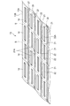
- FIG. 1 is a perspective view showing an air filter according to an embodiment of the present invention.
- the air filter 10 includes an air filter insert 12 for filtering air and an air filter frame 11 for holding the air filter insert 12.
- the air filter insert 12 is inserted into the air filter frame 11. Configured.
- the air filter frame 11 is formed in a square frame shape using a metal such as wood or aluminum.
- the air filter insert 12 is a filter medium in which a filter medium sheet 13 is folded into a pleat shape into a block shape.
- the filter medium sheet 13 is folded in a pleat shape (zigzag) at a constant folding height along the fold S extending along the width direction of the sheet 13.
- the air filter insert 12 has a structure in which a large number of planar folding walls 14 are stacked by folding the filter medium sheet 13 into a pleat shape.
- the direction in which the folding walls 14 are overlapped is defined as the X direction.
- air passes from the front surface 13 ⁇ / b> A to the back surface 13 ⁇ / b> B side of the filter medium sheet 13. That is, the ventilation direction is from the upper side to the lower side in FIG.
- the filter material sheet 13 may be any filter material as long as it can filter suspended particles in the air and can be molded into the air filter insert 12.
- filter paper made of glass fiber, polyolefin-based, or polyester-based non-woven fabric is used as the filter media sheet 13, but is not particularly limited as long as it is a filter media sheet that satisfies the filtration performance.
- the filter sheet 13 is provided with a large number of first and second protrusions 21 and 22 formed by embossing.
- the filter medium sheet 13 is, for example, sent in the longitudinal direction between two rollers provided with irregularities on the outer peripheral surface, and is embossed between these rollers.
- the first and second projecting portions 21 and 22 are recessed from one surface side (the front surface 13A or the back surface 13B side) of the sheet 13 and project to the other surface side (the back surface 13B or the front surface 13A side). To do.
- the first protrusions 21 and the second protrusions 22 are alternately arranged along the fold direction (the width direction of the sheet 13) in each fold wall 14.
- the interval between the first protrusions 21 in the fold direction is preferably 25 to 75 mm, and more preferably about 50 mm.
- the interval in the fold direction of the second protrusion 22 is preferably 25 to 75 mm, and more preferably about 50 mm.
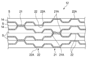
- Each of the first and second protrusions 21 and 22 provided on each folding wall 14 is in the same position as the first and second protrusions 21 and 22 provided on the other folding wall 14 in the fold direction. Placed in. That is, in the filter medium sheet 13, as shown in FIG. 2, the first protrusions 21 and the second protrusions 22 arranged in a line in the longitudinal direction of the sheet 13 are alternately arranged in the crease direction. .
- a plurality of first projecting portions 21 are arranged in the fold direction so as to project alternately to the front surface 13A side and the back surface 13B side in each folding wall 14.
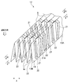
- the plurality of first protrusions 21 provided at the same position in the fold direction protrudes on the same surface side (the front surface 13A side or the back surface 13B side) of the filter material sheet 13. . Therefore, the plurality of first projecting portions 21 provided at the same position in the fold direction alternately project in one direction along the X direction and the opposite direction when folded in a pleat shape as shown in FIG. To do.
- the first projecting portion 21 projects so as to approach each other at the pair of adjacent folding walls 14 and 14, and the front end surfaces 21A and 21A are abutted with each other.
- the abutted tip surfaces 21A and 21A are fixed by an adhesive (not shown) applied therebetween, whereby the adjacent folded walls 14 and 14 are held apart.
- the 1st protrusion part 21 which protruded to the surface 13A side is between the surfaces 13A and 13A of the folding walls 14 and 14, and the 1st protrusion part 21 which protruded to the back surface 13B side is the back surface 13B of the folding walls 14 and 14. 13B is held apart.
- the plurality of second protrusions 22 arranged at the same position in the fold direction are alternately arranged on the front surface 13A side and the back surface 13B side along the longitudinal direction of the sheet 13. Protruding. Therefore, the second protrusions 22 arranged at the same position in the crease direction protrude in the same direction along the X direction when folded in a pleat shape, and are abutted against each other in the air filter insert 12. Absent.
- the second protrusions 22 are arranged in the fold direction so as to protrude alternately on the front surface 13A side and the back surface 13B side on each folding wall 14. Therefore, as shown in FIG. 3, in the air filter insert 12, the second projecting portion 22 projects in one direction along the X direction and in the opposite direction. They are arranged alternately.
- the first and second protrusions 21 and 22 have a shape that extends perpendicularly to the fold S in each fold wall 14. That is, the protrusions 21 and 22 extend in the longitudinal direction of the filter medium sheet 13 and extend slightly inclined with respect to the ventilation direction in the air filter insert 12.
- the first protrusions 21 are connected to the adjacent first protrusions 21 at the crease S, and a plurality of the first protrusions 21 are continuously arranged in the longitudinal direction of the sheet 13. That is, the length of the first protrusion 21 is the same as the width of the folding wall 14 (that is, the folding height).
- the second protrusion 22 is not formed near the fold S and is not connected to the adjacent second protrusion 22 at the fold S. That is, a plurality of the second protrusions 22 are arranged discontinuously in the longitudinal direction of the sheet 13, and the length of the second protrusions 22 is 1 ⁇ 2 to 2/3 of the folding height.
- the protrusion height of the first protrusion 21 increases along its longitudinal direction.
- the first protrusion 21 protruding toward the front surface 13A gradually decreases in height along the ventilation direction
- the first protrusion 21 protruding toward the back surface 13B gradually increases along the ventilation direction. Height increases. Therefore, the distance between the front surfaces 13A and 13A of the adjacent folded walls 14 and 14 gradually decreases along the ventilation direction, while the distance between the rear surfaces 13B and 13B gradually increases along the ventilation direction.
- the first projecting portion 21 has a trapezoidal cross-sectional shape, and its width gradually decreases from the proximal end toward the distal end. Becomes a plane. Note that the width at the base end of the first protrusion 21 is substantially constant in the longitudinal direction of the protrusion 21.
- the second protrusion 22 has a trapezoidal shape in cross section and vertical section, and its width and length gradually decrease from the base end to the tip end.
- the tip surface 22A is a plane parallel to the folding wall 14.
- the width of the second protrusion 22 (for example, the width of the distal end and the base end) is substantially constant in the longitudinal direction of the protrusion 22.
- the width at the base end of the protrusion 22 is preferably 5 to 15 mm, and more preferably about 10 mm.
- the protrusion height of the second protrusion 22 is constant in the direction perpendicular to the crease S.
- the protrusion height of the second protrusion 22 is a height between the height of the highest portion of the first protrusion 21 and the height of the lowest portion, specifically about 3 to 5 mm. Preferably there is. This is because if the height is less than 3 mm, the filtration area of the air filter insert 12 cannot be sufficiently increased, and if it is higher than 5 mm, the filter medium sheet may be damaged during embossing.
- the distal end side of the second protrusion 22 is disposed beyond the fold S when viewed from above as shown in FIG. Become.
- the plurality of second protrusions 22 arranged at the same position in the crease direction protrude in the same direction in the X direction, and the tip side of the second protrusion 22 is The width and length are smaller than the proximal side. Therefore, as shown in FIGS. 5 and 6, a part of the distal end side of the second protrusion 22 beyond the crease S is partly inside the proximal end of the adjacent second protrusion 22 (inside the recess). ) And the second protrusions 22 do not come into contact with each other.
- the plurality of second protrusions 22 arranged at the same position in the crease direction has one end in the longitudinal direction inside the other end of the other protrusion 22. And one end of the other protrusion 22 is arranged inside the other end, and this is repeated.
- the area of the air filter insert 12 is increased. Can do. Since the 2nd protrusion part 22 is not faced
- the second protrusions 22 arranged at the same position in the fold direction protrude in the same direction, and a part of each of the second protrusions 22 is another second protrusion 22. Placed inside. Therefore, it becomes possible to make each protrusion height of the 2nd protrusion part 22 comparatively large, and it becomes easy to increase an effective filtration area. Moreover, since the front end surface 22A is flat and the second projecting portion 22 has a trapezoidal cross section and longitudinal section, it is possible to improve the rigidity of each folding wall 14 while efficiently improving the filter medium area. it can. Furthermore, since the second protrusion 22 has a substantially constant width and height in the longitudinal direction, it is easy to pass air in the ventilation direction.
- the second protrusions 22 are alternately arranged in the fold direction in the crease direction and in the fold direction. Therefore, the rigidity of the folded wall 14 can be further improved, and air can be easily passed through the air filter insert 12.
Landscapes
- Chemical & Material Sciences (AREA)
- Chemical Kinetics & Catalysis (AREA)
- Filtering Of Dispersed Particles In Gases (AREA)
- Filtering Materials (AREA)
Abstract
Description
13 濾材シート
14 折り壁
21 第1の突出部
22 第2の突出部
図1は、本発明の一実施形態に係るエアフィルタを示す斜視図である。
エアフィルタ10は、空気を濾過するためのエアフィルタ挿入体12と、エアフィルタ挿入体12を保持するためのエアフィルタ枠11とを備え、エアフィルタ挿入体12がエアフィルタ枠11の内部に挿入されて構成される。エアフィルタ枠11は、木材、アルミニウム等の金属等で四角枠状に形成される。エアフィルタ挿入体12は、濾材シート13がひだ状に折られてブロック状にされた濾材である。
Claims (12)
- 濾材シートがひだ状に折られて、ブロック状の構造を有し、空気を濾過するためのエアフィルタ挿入体において、
前記濾材シートは折られることにより複数の折り壁が形成され、前記折り壁それぞれにエンボス加工によって成形された第1の突出部と第2の突出部とが折目方向に並べられ、
隣接する一対の前記折り壁に設けられた前記第1の突出部は、互いに近づくように突出し、先端同士が突き合わされるとともに、
前記第2の突出部は、互いに突き合わされないように突出することを特徴とするエアフィルタ挿入体。 - 前記第2の突出部は、互いに折目方向における同一位置に配置され、かつ同一方向に突出することを特徴とする請求項1に記載のエアフィルタ挿入体。
- 前記折り壁それぞれに設けられた前記第2の突出部それぞれはその一部が、その折り壁に隣接する折り壁に設けられた前記第2の突出部の内部に配置されることを特徴とする請求項2に記載のエアフィルタ挿入体。
- 前記第2の突出部は、一方向に突出するものと、その反対方向に突出するものが、折目方向において交互に並べられることを特徴とする請求項2に記載のエアフィルタ挿入体。
- 前記第2の突出部は、互いに接触しないように突出することを特徴とする請求項1に記載のエアフィルタ挿入体。
- 前記第2の突出部は、各折り壁において、折目に対して垂直に延びる形状を有することを特徴とする請求項1に記載のエアフィルタ挿入体。
- 前記第2の突出部は、その横断面形状及び縦断面形状の少なくとも一方が台形であることを特徴とする請求項6に記載のエアフィルタ挿入体。
- 前記第2の突出部は、その横断面形状及び縦断面形状のいずれもが台形であることを特徴とする請求項7に記載のエアフィルタ挿入体。
- 前記第2の突出部の突出高さが、その長手方向に沿って略一定であることを特徴とする請求項6に記載のエアフィルタ挿入体。
- 前記第2の突出部の先端面は、前記折り壁に平行な平面であることを特徴とする請求項1に記載のエアフィルタ挿入体。
- 前記第1の突出部は、各折り壁において、折目に対して垂直に延び、かつその長手方向に沿って突出高さが増大することを特徴とする請求項1に記載のエアフィルタ挿入体。
- 前記第1及び第2の突出部は、折目方向に交互に並べられることを特徴とする請求項1に記載のエアフィルタ挿入体。
Priority Applications (3)
| Application Number | Priority Date | Filing Date | Title |
|---|---|---|---|
| KR1020127033774A KR101803855B1 (ko) | 2010-07-02 | 2011-06-20 | 에어 필터 삽입체 |
| SG2012096376A SG186482A1 (en) | 2010-07-02 | 2011-06-20 | Air filter insert |
| CN201180032699.4A CN102958582B (zh) | 2010-07-02 | 2011-06-20 | 空气过滤器插入体 |
Applications Claiming Priority (2)
| Application Number | Priority Date | Filing Date | Title |
|---|---|---|---|
| JP2010-151874 | 2010-07-02 | ||
| JP2010151874A JP5602521B2 (ja) | 2010-07-02 | 2010-07-02 | エアフィルタ挿入体 |
Publications (1)
| Publication Number | Publication Date |
|---|---|
| WO2012002187A1 true WO2012002187A1 (ja) | 2012-01-05 |
Family
ID=45401908
Family Applications (1)
| Application Number | Title | Priority Date | Filing Date |
|---|---|---|---|
| PCT/JP2011/064008 Ceased WO2012002187A1 (ja) | 2010-07-02 | 2011-06-20 | エアフィルタ挿入体 |
Country Status (7)
| Country | Link |
|---|---|
| JP (1) | JP5602521B2 (ja) |
| KR (1) | KR101803855B1 (ja) |
| CN (1) | CN102958582B (ja) |
| MY (1) | MY157537A (ja) |
| SG (1) | SG186482A1 (ja) |
| TW (1) | TWI520767B (ja) |
| WO (1) | WO2012002187A1 (ja) |
Families Citing this family (10)
| Publication number | Priority date | Publication date | Assignee | Title |
|---|---|---|---|---|
| JP2014064995A (ja) * | 2012-09-26 | 2014-04-17 | Japan Vilene Co Ltd | フィルタエレメント |
| JP2014113532A (ja) * | 2012-12-07 | 2014-06-26 | Nitto Denko Corp | フィルタ濾材およびフィルタ濾材の製造方法 |
| EP2803310A1 (de) | 2013-05-17 | 2014-11-19 | HILTI Aktiengesellschaft | Staubabsaugvorrichtung für eine Handwerkzeugmaschine |
| CN106488794B (zh) * | 2014-05-22 | 2019-07-19 | 酷思滤清系统有限公司 | 形成用于维持通过滤袋式过滤器的流动通道的过滤介质 |
| WO2020067486A1 (ja) * | 2018-09-28 | 2020-04-02 | ダイキン工業株式会社 | エアフィルタ濾材、フィルタパック、エアフィルタユニット、およびこれらの製造方法 |
| US10773198B2 (en) * | 2018-10-24 | 2020-09-15 | Pall Corporation | Support and drainage material, filter, and method of use |
| CN110448973B (zh) * | 2019-08-07 | 2021-09-17 | 九江七所精密机电科技有限公司 | 一种锥形筒式空气滤芯及其制作工艺 |
| JP7688019B2 (ja) | 2019-08-26 | 2025-06-03 | パーカー-ハネフィン コーポレーション | 構造的エンボス加工を使用する燃料水分離の強化 |
| JP2021154278A (ja) * | 2020-03-26 | 2021-10-07 | ニッタ株式会社 | エアフィルタ及び製造方法 |
| TWI873565B (zh) * | 2022-03-15 | 2025-02-21 | 日商大金工業股份有限公司 | 空氣過濾器濾材、空氣過濾器件及空氣過濾器單元 |
Citations (9)
| Publication number | Priority date | Publication date | Assignee | Title |
|---|---|---|---|---|
| JPS5518293A (en) * | 1978-05-31 | 1980-02-08 | Engineering Components Ltd | Filter element with gradient of paper with pleat and air filter provided with said element |
| JPS596916A (ja) * | 1982-06-18 | 1984-01-14 | ダナルドスン・カムパニ・インコ−パレイテイド | ひだスペ−シング手段 |
| JPS6355971B2 (ja) * | 1980-05-02 | 1988-11-07 | Taikisha Kk | |
| JPS6467213A (en) * | 1987-05-14 | 1989-03-13 | Aisan Ind | Fluid filter |
| JPH0291604U (ja) * | 1988-12-27 | 1990-07-20 | ||
| JPH0319507U (ja) * | 1989-07-05 | 1991-02-26 | ||
| JPH05504092A (ja) * | 1990-02-08 | 1993-07-01 | ニッタ株式会社 | フィルタ挿入体 |
| JP2000000488A (ja) * | 1998-04-15 | 2000-01-07 | Matsushita Seiko Co Ltd | 電気集塵フィルタとその製造方法 |
| JP2009011887A (ja) * | 2007-06-29 | 2009-01-22 | Nippon Muki Co Ltd | プリーツ型エアフィルタパック及びそれを用いたエアフィルタ |
Family Cites Families (2)
| Publication number | Priority date | Publication date | Assignee | Title |
|---|---|---|---|---|
| US3531920A (en) * | 1968-09-16 | 1970-10-06 | Cambridge Filter Corp | Filter |
| WO1995017943A2 (de) * | 1993-12-30 | 1995-07-06 | Detroit Holding Limited | Filtereinsatz und verfahren zu dessen herstellung |
-
2010
- 2010-07-02 JP JP2010151874A patent/JP5602521B2/ja active Active
-
2011
- 2011-06-20 KR KR1020127033774A patent/KR101803855B1/ko active Active
- 2011-06-20 WO PCT/JP2011/064008 patent/WO2012002187A1/ja not_active Ceased
- 2011-06-20 SG SG2012096376A patent/SG186482A1/en unknown
- 2011-06-20 CN CN201180032699.4A patent/CN102958582B/zh active Active
- 2011-06-20 MY MYPI2012005615A patent/MY157537A/en unknown
- 2011-06-28 TW TW100122667A patent/TWI520767B/zh active
Patent Citations (9)
| Publication number | Priority date | Publication date | Assignee | Title |
|---|---|---|---|---|
| JPS5518293A (en) * | 1978-05-31 | 1980-02-08 | Engineering Components Ltd | Filter element with gradient of paper with pleat and air filter provided with said element |
| JPS6355971B2 (ja) * | 1980-05-02 | 1988-11-07 | Taikisha Kk | |
| JPS596916A (ja) * | 1982-06-18 | 1984-01-14 | ダナルドスン・カムパニ・インコ−パレイテイド | ひだスペ−シング手段 |
| JPS6467213A (en) * | 1987-05-14 | 1989-03-13 | Aisan Ind | Fluid filter |
| JPH0291604U (ja) * | 1988-12-27 | 1990-07-20 | ||
| JPH0319507U (ja) * | 1989-07-05 | 1991-02-26 | ||
| JPH05504092A (ja) * | 1990-02-08 | 1993-07-01 | ニッタ株式会社 | フィルタ挿入体 |
| JP2000000488A (ja) * | 1998-04-15 | 2000-01-07 | Matsushita Seiko Co Ltd | 電気集塵フィルタとその製造方法 |
| JP2009011887A (ja) * | 2007-06-29 | 2009-01-22 | Nippon Muki Co Ltd | プリーツ型エアフィルタパック及びそれを用いたエアフィルタ |
Also Published As
| Publication number | Publication date |
|---|---|
| CN102958582A (zh) | 2013-03-06 |
| JP2012011345A (ja) | 2012-01-19 |
| KR101803855B1 (ko) | 2017-12-04 |
| KR20130124173A (ko) | 2013-11-13 |
| TWI520767B (zh) | 2016-02-11 |
| MY157537A (en) | 2016-06-15 |
| SG186482A1 (en) | 2013-02-28 |
| JP5602521B2 (ja) | 2014-10-08 |
| CN102958582B (zh) | 2014-12-17 |
| TW201206540A (en) | 2012-02-16 |
Similar Documents
| Publication | Publication Date | Title |
|---|---|---|
| JP5602521B2 (ja) | エアフィルタ挿入体 | |
| ES2911332T3 (es) | Filtro de aire con miembro de soporte de tracción | |
| ES2401472T3 (es) | Conjunto de medios para filtración de aire | |
| WO2009156911A2 (en) | Air filter with integral inter-filter gap filler | |
| WO2014003011A1 (ja) | エアフィルタユニット | |
| JP7075190B2 (ja) | エアフィルタ、及びフィルタパック | |
| KR102284703B1 (ko) | 공기정화용 에어필터모듈 | |
| TWI846701B (zh) | 過濾器組件及空氣過濾器 | |
| JP7858630B2 (ja) | フィルタパックおよびそれを備えるエアフィルタ | |
| KR20200137668A (ko) | 에어 필터 팩 및 그를 포함하는 에어 필터 | |
| JP7507590B2 (ja) | エアフィルタ、及びフィルタパック | |
| JP2015208701A (ja) | フィルタ枠およびエアフィルタ | |
| JP2008188499A (ja) | 空気浄化用フィルタ | |
| HK1178481A (en) | Air filter insert | |
| JP6262622B2 (ja) | フィルタ枠およびエアフィルタ | |
| JP2021098161A (ja) | フィルタパック、及びエアフィルタ | |
| JP2012139651A (ja) | フィルタエレメント | |
| JP2009297666A (ja) | プリーツ状エアフィルター及びその製法 | |
| JP2018051510A (ja) | エアフィルタ、およびエアフィルタの製造方法 | |
| JP5047033B2 (ja) | エアフィルタ | |
| JP7748244B2 (ja) | エアフィルタ | |
| US11071936B2 (en) | Filter with perforated separator plates | |
| JP7221643B2 (ja) | フィルタ枠、およびエアフィルタ | |
| JP2007289907A (ja) | 空調フィルタのセパレータ | |
| JP2025151717A (ja) | フィルタパックおよびそれを備えるエアフィルタ |
Legal Events
| Date | Code | Title | Description |
|---|---|---|---|
| WWE | Wipo information: entry into national phase |
Ref document number: 201180032699.4 Country of ref document: CN |
|
| 121 | Ep: the epo has been informed by wipo that ep was designated in this application |
Ref document number: 11800652 Country of ref document: EP Kind code of ref document: A1 |
|
| DPE1 | Request for preliminary examination filed after expiration of 19th month from priority date (pct application filed from 20040101) | ||
| ENP | Entry into the national phase |
Ref document number: 20127033774 Country of ref document: KR Kind code of ref document: A |
|
| NENP | Non-entry into the national phase |
Ref country code: DE |
|
| WWE | Wipo information: entry into national phase |
Ref document number: 1201006865 Country of ref document: TH |
|
| 122 | Ep: pct application non-entry in european phase |
Ref document number: 11800652 Country of ref document: EP Kind code of ref document: A1 |