WO2011161887A1 - 端末装置及びその通信方法 - Google Patents
端末装置及びその通信方法 Download PDFInfo
- Publication number
- WO2011161887A1 WO2011161887A1 PCT/JP2011/003198 JP2011003198W WO2011161887A1 WO 2011161887 A1 WO2011161887 A1 WO 2011161887A1 JP 2011003198 W JP2011003198 W JP 2011003198W WO 2011161887 A1 WO2011161887 A1 WO 2011161887A1
- Authority
- WO
- WIPO (PCT)
- Prior art keywords
- indicates
- control information
- layers
- initial
- resource amount
- Prior art date
Links
- 238000000034 method Methods 0.000 title claims description 72
- 238000004891 communication Methods 0.000 title claims description 15
- 230000005540 biological transmission Effects 0.000 claims abstract description 197
- 238000012937 correction Methods 0.000 claims description 104
- 230000007274 generation of a signal involved in cell-cell signaling Effects 0.000 claims description 25
- 238000011144 upstream manufacturing Methods 0.000 claims 2
- 230000015556 catabolic process Effects 0.000 abstract 1
- 238000006731 degradation reaction Methods 0.000 abstract 1
- 239000010410 layer Substances 0.000 description 224
- 101000741965 Homo sapiens Inactive tyrosine-protein kinase PRAG1 Proteins 0.000 description 88
- 102100038659 Inactive tyrosine-protein kinase PRAG1 Human genes 0.000 description 88
- 102100036409 Activated CDC42 kinase 1 Human genes 0.000 description 85
- 238000012545 processing Methods 0.000 description 49
- 230000011664 signaling Effects 0.000 description 17
- 238000006243 chemical reaction Methods 0.000 description 13
- 230000007423 decrease Effects 0.000 description 10
- 230000006866 deterioration Effects 0.000 description 10
- 239000011229 interlayer Substances 0.000 description 10
- 238000010586 diagram Methods 0.000 description 8
- 238000013468 resource allocation Methods 0.000 description 8
- 239000011159 matrix material Substances 0.000 description 5
- 239000002131 composite material Substances 0.000 description 4
- 238000005516 engineering process Methods 0.000 description 4
- 230000003247 decreasing effect Effects 0.000 description 3
- 238000001514 detection method Methods 0.000 description 3
- 230000010354 integration Effects 0.000 description 3
- 108010076504 Protein Sorting Signals Proteins 0.000 description 2
- 125000004122 cyclic group Chemical group 0.000 description 2
- 238000013459 approach Methods 0.000 description 1
- 230000007812 deficiency Effects 0.000 description 1
- 230000001934 delay Effects 0.000 description 1
- 230000001419 dependent effect Effects 0.000 description 1
- 238000013461 design Methods 0.000 description 1
- GVVPGTZRZFNKDS-JXMROGBWSA-N geranyl diphosphate Chemical compound CC(C)=CCC\C(C)=C\CO[P@](O)(=O)OP(O)(O)=O GVVPGTZRZFNKDS-JXMROGBWSA-N 0.000 description 1
- 230000007774 longterm Effects 0.000 description 1
- 238000013507 mapping Methods 0.000 description 1
- 239000000203 mixture Substances 0.000 description 1
- 238000010295 mobile communication Methods 0.000 description 1
- 239000004065 semiconductor Substances 0.000 description 1
- 238000000926 separation method Methods 0.000 description 1
- 238000004260 weight control Methods 0.000 description 1
Images


Classifications
-
- H—ELECTRICITY
- H04—ELECTRIC COMMUNICATION TECHNIQUE
- H04W—WIRELESS COMMUNICATION NETWORKS
- H04W28/00—Network traffic management; Network resource management
- H04W28/02—Traffic management, e.g. flow control or congestion control
- H04W28/06—Optimizing the usage of the radio link, e.g. header compression, information sizing, discarding information
-
- H—ELECTRICITY
- H04—ELECTRIC COMMUNICATION TECHNIQUE
- H04L—TRANSMISSION OF DIGITAL INFORMATION, e.g. TELEGRAPHIC COMMUNICATION
- H04L5/00—Arrangements affording multiple use of the transmission path
- H04L5/003—Arrangements for allocating sub-channels of the transmission path
- H04L5/0053—Allocation of signaling, i.e. of overhead other than pilot signals
-
- H—ELECTRICITY
- H04—ELECTRIC COMMUNICATION TECHNIQUE
- H04B—TRANSMISSION
- H04B7/00—Radio transmission systems, i.e. using radiation field
- H04B7/02—Diversity systems; Multi-antenna system, i.e. transmission or reception using multiple antennas
- H04B7/04—Diversity systems; Multi-antenna system, i.e. transmission or reception using multiple antennas using two or more spaced independent antennas
- H04B7/0413—MIMO systems
- H04B7/0452—Multi-user MIMO systems
-
- H—ELECTRICITY
- H04—ELECTRIC COMMUNICATION TECHNIQUE
- H04B—TRANSMISSION
- H04B7/00—Radio transmission systems, i.e. using radiation field
- H04B7/02—Diversity systems; Multi-antenna system, i.e. transmission or reception using multiple antennas
- H04B7/04—Diversity systems; Multi-antenna system, i.e. transmission or reception using multiple antennas using two or more spaced independent antennas
- H04B7/06—Diversity systems; Multi-antenna system, i.e. transmission or reception using multiple antennas using two or more spaced independent antennas at the transmitting station
- H04B7/0613—Diversity systems; Multi-antenna system, i.e. transmission or reception using multiple antennas using two or more spaced independent antennas at the transmitting station using simultaneous transmission
- H04B7/0615—Diversity systems; Multi-antenna system, i.e. transmission or reception using multiple antennas using two or more spaced independent antennas at the transmitting station using simultaneous transmission of weighted versions of same signal
- H04B7/0619—Diversity systems; Multi-antenna system, i.e. transmission or reception using multiple antennas using two or more spaced independent antennas at the transmitting station using simultaneous transmission of weighted versions of same signal using feedback from receiving side
- H04B7/0621—Feedback content
- H04B7/0623—Auxiliary parameters, e.g. power control [PCB] or not acknowledged commands [NACK], used as feedback information
-
- H—ELECTRICITY
- H04—ELECTRIC COMMUNICATION TECHNIQUE
- H04J—MULTIPLEX COMMUNICATION
- H04J11/00—Orthogonal multiplex systems, e.g. using WALSH codes
-
- H—ELECTRICITY
- H04—ELECTRIC COMMUNICATION TECHNIQUE
- H04L—TRANSMISSION OF DIGITAL INFORMATION, e.g. TELEGRAPHIC COMMUNICATION
- H04L1/00—Arrangements for detecting or preventing errors in the information received
- H04L1/12—Arrangements for detecting or preventing errors in the information received by using return channel
- H04L1/16—Arrangements for detecting or preventing errors in the information received by using return channel in which the return channel carries supervisory signals, e.g. repetition request signals
- H04L1/1607—Details of the supervisory signal
- H04L1/1671—Details of the supervisory signal the supervisory signal being transmitted together with control information
-
- H—ELECTRICITY
- H04—ELECTRIC COMMUNICATION TECHNIQUE
- H04L—TRANSMISSION OF DIGITAL INFORMATION, e.g. TELEGRAPHIC COMMUNICATION
- H04L1/00—Arrangements for detecting or preventing errors in the information received
- H04L1/12—Arrangements for detecting or preventing errors in the information received by using return channel
- H04L1/16—Arrangements for detecting or preventing errors in the information received by using return channel in which the return channel carries supervisory signals, e.g. repetition request signals
- H04L1/18—Automatic repetition systems, e.g. Van Duuren systems
- H04L1/1829—Arrangements specially adapted for the receiver end
- H04L1/1861—Physical mapping arrangements
-
- H—ELECTRICITY
- H04—ELECTRIC COMMUNICATION TECHNIQUE
- H04L—TRANSMISSION OF DIGITAL INFORMATION, e.g. TELEGRAPHIC COMMUNICATION
- H04L5/00—Arrangements affording multiple use of the transmission path
- H04L5/0001—Arrangements for dividing the transmission path
- H04L5/0014—Three-dimensional division
- H04L5/0023—Time-frequency-space
-
- H—ELECTRICITY
- H04—ELECTRIC COMMUNICATION TECHNIQUE
- H04L—TRANSMISSION OF DIGITAL INFORMATION, e.g. TELEGRAPHIC COMMUNICATION
- H04L5/00—Arrangements affording multiple use of the transmission path
- H04L5/003—Arrangements for allocating sub-channels of the transmission path
- H04L5/0053—Allocation of signaling, i.e. of overhead other than pilot signals
- H04L5/0055—Physical resource allocation for ACK/NACK
-
- H—ELECTRICITY
- H04—ELECTRIC COMMUNICATION TECHNIQUE
- H04L—TRANSMISSION OF DIGITAL INFORMATION, e.g. TELEGRAPHIC COMMUNICATION
- H04L5/00—Arrangements affording multiple use of the transmission path
- H04L5/003—Arrangements for allocating sub-channels of the transmission path
- H04L5/0053—Allocation of signaling, i.e. of overhead other than pilot signals
- H04L5/0057—Physical resource allocation for CQI
-
- H—ELECTRICITY
- H04—ELECTRIC COMMUNICATION TECHNIQUE
- H04W—WIRELESS COMMUNICATION NETWORKS
- H04W28/00—Network traffic management; Network resource management
- H04W28/02—Traffic management, e.g. flow control or congestion control
-
- H—ELECTRICITY
- H04—ELECTRIC COMMUNICATION TECHNIQUE
- H04W—WIRELESS COMMUNICATION NETWORKS
- H04W72/00—Local resource management
- H04W72/20—Control channels or signalling for resource management
-
- H—ELECTRICITY
- H04—ELECTRIC COMMUNICATION TECHNIQUE
- H04W—WIRELESS COMMUNICATION NETWORKS
- H04W72/00—Local resource management
- H04W72/20—Control channels or signalling for resource management
- H04W72/21—Control channels or signalling for resource management in the uplink direction of a wireless link, i.e. towards the network
-
- H—ELECTRICITY
- H04—ELECTRIC COMMUNICATION TECHNIQUE
- H04W—WIRELESS COMMUNICATION NETWORKS
- H04W88/00—Devices specially adapted for wireless communication networks, e.g. terminals, base stations or access point devices
- H04W88/02—Terminal devices
-
- H—ELECTRICITY
- H04—ELECTRIC COMMUNICATION TECHNIQUE
- H04W—WIRELESS COMMUNICATION NETWORKS
- H04W88/00—Devices specially adapted for wireless communication networks, e.g. terminals, base stations or access point devices
- H04W88/08—Access point devices
-
- H—ELECTRICITY
- H04—ELECTRIC COMMUNICATION TECHNIQUE
- H04L—TRANSMISSION OF DIGITAL INFORMATION, e.g. TELEGRAPHIC COMMUNICATION
- H04L27/00—Modulated-carrier systems
- H04L27/26—Systems using multi-frequency codes
- H04L27/2601—Multicarrier modulation systems
- H04L27/2626—Arrangements specific to the transmitter only
- H04L27/2627—Modulators
- H04L27/2634—Inverse fast Fourier transform [IFFT] or inverse discrete Fourier transform [IDFT] modulators in combination with other circuits for modulation
- H04L27/2636—Inverse fast Fourier transform [IFFT] or inverse discrete Fourier transform [IDFT] modulators in combination with other circuits for modulation with FFT or DFT modulators, e.g. standard single-carrier frequency-division multiple access [SC-FDMA] transmitter or DFT spread orthogonal frequency division multiplexing [DFT-SOFDM]
Definitions
- the present invention relates to a terminal device and a communication method thereof.
- CM Cubic Metric
- ACK / NACK Physical Uplink Shared CHannel
- CQI channel quality indicator
- the data signal is divided into several code blocks (CB: Code Blocks), and a cyclic redundancy check (CRC) for error correction is added on a code block basis.
- Allocation methods differ between these ACK / NACK signals and CQIs (see, for example, Non-Patent Documents 1 and 2).
- the ACK / NACK signal punctures a part of the data signal (4 symbols) mapped to the resource adjacent to the pilot signal (Reference Signal, RS) (overwrites the data signal with the ACK / NACK signal).
- RS Reference Signal
- CQIs are allocated over the entire subframe (two slots). At this time, since the data signal is allocated to resources other than the resource to which the CQI is allocated, it is not punctured by the CQI (see FIG. 1).
- the presence or absence of allocation of the ACK / NACK signal is determined according to the presence or absence of the downlink data signal. That is, since it is more difficult to predict the occurrence of an ACK / NACK signal in advance compared to CQI, puncturing that allows resource allocation even if an ACK / NACK signal suddenly occurs in mapping of the ACK / NACK signal is possible. Used. On the other hand, since CQI transmission timing (subframe) is determined in advance by notification information, resources of data signals and CQI can be determined. Since the ACK / NACK signal is important information, the ACK / NACK signal is assigned to a symbol close to the pilot signal, which has high channel estimation accuracy. This can reduce errors in the ACK / NACK signal.
- MCS Modulation and Coding Rate Scheme
- base station a base station apparatus
- eNB base station apparatus
- the MCS for uplink control information is determined by adding an offset to the MCS of the data signal (for example, see Non-Patent Document 1).
- the control information is more important information than the data signal
- an MCS having a transmission rate lower than that of the data signal is set as the control information MCS. Thereby, control information is transmitted with high quality.
- the amount of resources allocated to the control information is determined based on the coding rate indicated in the MCS of the data signal. Specifically, as shown in the following equation (1), the resource amount Q allocated to the control information is derived by multiplying the reciprocal of the coding rate of the data signal by the offset.
- O indicates the number of bits of control information (ACK / NACK signal or CQI)
- P indicates the number of bits added to control information for error correction (for example, the number of bits of CRC, where P is the number).
- O indicates the number of bits of CRC (CRC)
- P indicates the number of bits of UCI (Uplink Control Information).
- M SC PUSCH-initial indicates the transmission bandwidth of PUSCH
- N Symb PUSCH-initial indicates the number of transmission symbols of PUSCH per unit transmission bandwidth
- C indicates the number of divisions when the data signal is divided into code blocks.
- K r indicates the number of bits in each code block.
- UCI (control information) includes ACK / NACK, CQI, RI (Rank Indicator, information on rank), PMI (Precoding Matrix Indicator, information on precoding), and the like.
- Equation (1) (M SC PUSCH -initial ⁇ N Symb PUSCH-initial) represents transmission resource amount of the data signal, .sigma.k r is divided into the number of bits (number of one data signal Indicates the total number of bits of each code block). Therefore, KK r / (M SC PUSCH -initial ⁇ N Symb PUSCH -initial ) represents a value dependent on the coding rate of the data signal (hereinafter also referred to as the coding rate).
- Equation (1) is the reciprocal of the coding rate of the data signal (ie, RE (Resource Element, 1 symbol used for transmission of 1 bit) And the number of resources configured by one subcarrier).
- ⁇ offset PUSCH indicates an offset amount to be multiplied by the reciprocal of the coding rate of the data signal described above, and from the base station via the upper layer to each terminal apparatus (hereinafter referred to as “terminal” or UE). May be notified).
- terminal terminal apparatus
- the base station selects one offset amount ⁇ offset PUSCH from a table (see, eg, FIG. 2) indicating offset amount ⁇ offset PUSCH candidates defined for the ACK / NACK signal, and responds to the selected offset amount.
- the notification index to be notified to the terminal.
- (M SC PUSCH-initial ⁇ N Symb PUSCH-initial) as can be judged from the statement that PUSCH-initial, a transmission resource amount of the data signal at the time of initial transmission.
- LTE-A system 3GPP LTE-Advanced system
- LTE system 3GPP LTE system
- SU-MIMO Single User Multiple Input Multiple Output
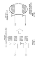
- a data signal is generated by a plurality of codewords (CWs), and each CW is transmitted in a different layer.
- CW # 0 is transmitted on layer # 0 and layer # 1
- CW # 1 is transmitted on layer # 2 and layer # 3.
- the data signal is divided into several code blocks, and a CRC for error correction is added in code block units.
- the data signal of CW # 0 is divided into five code blocks, and the data signal of CW # 1 is divided into eight code blocks.
- the "codeword” can be regarded as a unit for retransmitting a data signal.
- layer is synonymous with stream.
- Non-MIMO transmission is assumed. In this Non-MIMO transmission, only one layer is used at each terminal.
- control information is transmitted in multiple layers and that control information is transmitted in one of the multiple layers.
- control information is transmitted in one of the multiple layers.
- it is considered to allocate ACK / NACK signals to a plurality of CWs and to allocate CQIs to one CW.
- the ACK / NACK signal is one of the most important information in the control information, the same signal is allocated to all CWs (that is, transmission in which the same information is allocated to all layers (Rank 1 transmission) To reduce inter-layer interference.
- the ACK / NACK signal (spatial multiplexed ACK / NACK signal) transmitted by a plurality of CWs is combined with the ACK / NACK signal transmitted by a plurality of CWs at the receiving side (base station side).
- the control information is an ACK / NACK signal and the control information is arranged in two CWs (CW # 0 and CW # 1).
- TS 36.212 v8.7.0 “3GPP TSG RAN; Evolved Universal Terrestrial Radio Access (E-UTRA); Multiplexing and channel coding TS 36.213 v8.8.0, “3GPP TSG RAN; Evolved Universal Terrestrial Radio Access (E-UTRA); Physical Layer Procedure
- control information (ACK / A) is transmitted based on an arbitrary CW coding rate of two CWs in the same manner as in the LTE system (eg, Non-Patent Document 1). It is conceivable to determine the amount of resources required to allocate the NACK signal. For example, as shown in the following equation (2), the amount of resources required for allocation of control information in each layer based on the coding rate r CW # 0 of CW # 0 among two CW # 0 and CW # 1 Q Determine CW # 0 .
- Equation (2) L indicates the total number of layers (the total number of layers to which CW # 0 and CW # 1 are allocated). That is, in the equation (2), the result of multiplying the reciprocal of the coding rate r CW # 0 (1 / r CW # 0 ) by the offset amount ⁇ offset PUSCH in the same manner as the equation (1) is By dividing, the amount of resources required to allocate control information is determined in each layer. Then, the terminal transmits CW # 0 and CW # 1 respectively allocated to each layer (L layers) using the resource amount Q CW # 0 determined according to Equation (2).
- CW # 0 is transmitted using a resource amount Q CW # 0 determined based on the coding rate r CW # 0 of CW # 0 , that is, an appropriate resource amount for CW # 0.
- CW # 1 is transmitted using the resource amount Q CW # 0 determined based on the coding rate r CW # 0 of CW # 0 (that is, other CWs)
- CW # 1 is allocated. If the selected layer is in a poor propagation path environment, there is a possibility that the reception quality for control information allocated to CW # 1 may be degraded.
- the reception quality required for each CW (reception quality / number of CWs required for control information in LTE system) It can be secured.
- the resource amount determined based on the CW # 0 is used for the control information arranged in the CW # 1, so that the required reception quality can be satisfied. Due to lack of resources, it becomes impossible to secure the reception quality required for each CW. Therefore, even if the control information allocated to each of CW # 0 and CW # 1 is synthesized, the reception quality required for all CWs (the reception quality required for control information in the LTE system) is lower There is.
- An object of the present invention is to provide a terminal capable of preventing deterioration of reception quality of control information and a communication method thereof even when the SU-MIMO transmission method is adopted.
- the terminal device is a terminal device that transmits two code words in which control information is arranged in different layers, and the resource amount of the control information in each of the plurality of layers is And a transmission signal generation unit configured to generate a transmission signal by arranging the control information modulated using the resource amount in the two codewords, the determination unit comprising: The resource amount is determined based on the lower coding rate of the coding rates of the two codewords or the average value of the reciprocal of the coding rates of the two codewords.
- a communication method determines the resource amount of the control information in each of a plurality of different layers to which two codewords in which the control information is arranged is transmitted, and uses the resource amount.
- the present invention even when the SU-MIMO transmission method is adopted, it is possible to prevent the deterioration of the reception quality of control information.
- Block diagram showing configuration of terminal according to Embodiment 1 of the present invention The figure which shows an example of the correction coefficient which concerns on Embodiment 1 of this invention.
- a communication system including a base station 100 and a terminal 200 described later is, for example, an LTE-A system
- the base station 100 is, for example, an LTE-A base station
- the terminal 200 is, for example, an LTE -A terminal.
- this communication system assumes a frequency division duplex (FDD) system.
- terminal 200 (LTE-A terminal) has a configuration capable of switching between Non-MIMO transmission mode and SU-MIMO transmission mode.
- FIG. 4 is a block diagram showing a configuration of base station 100 according to the present embodiment.
- configuration section 101 performs uplink data channel uplink in communication with the setting target terminal based on the terminal transmission / reception capability (UE Capability) of the setting target terminal or the propagation path status ( Control parameters related to resource allocation of control information (including at least an ACK / NACK signal or CQI) transmitted on PUSCH) are set.
- a control parameter for example, an offset amount (for example, an offset amount ⁇ offset PUSCH shown in equation (2)) used at the time of resource allocation of control information transmitted by the setting target terminal can be mentioned.
- setting section 101 outputs setting information including the set control parameter to coding / modulation section 102 and ACK / NACK / CQI reception section 111.
- setting section 101 generates allocation control information including MCS information for one CW (or transport block) and resource (RB (Resource Block)) allocation information for a terminal that performs non-MIMO transmission. Do. Further, setting section 101 generates allocation control information including MCS information and the like for two CWs (or transport blocks) for a terminal that performs SU-MIMO transmission.
- uplink assignment control information indicating uplink resources (for example, PUSCH (Physical Uplink Shared Channel)) to which uplink data of the terminal is assigned, and to the terminal Downlink allocation control information indicating downlink resources (for example, PDSCH (Physical Downlink Shared Channel)) to which downlink data are to be allocated is included.
- the downlink allocation control information includes information (ACK / NACK information) indicating the number of bits of an ACK / NACK signal for downlink data.
- setting section 101 outputs uplink allocation control information to coding / modulation section 102, each reception processing section 109 of reception sections 107-1 to 107-N, and ACK / NACK / CQI reception section 111.
- the downlink allocation control information is output to transmission signal generation section 104 and ACK / NACK / CQI reception section 111.
- Encoding / modulation section 102 modulates the setting information and uplink allocation control information input from setting section 101 after encoding, and outputs the modulated signal to transmission signal generation section 104.
- Encoding / modulation section 103 modulates the input transmission data after modulation, and outputs the modulated data signal (for example, PDSCH signal) to transmission signal generation section 104.
- the modulated data signal for example, PDSCH signal
- Transmission signal generation section 104 receives a signal input from encoding / modulation section 102 and a data signal input from encoding / modulation section 103 based on the downlink allocation control information input from setting section 101. , Assign to frequency resources to generate signals in the frequency domain. Then, the transmission signal generation unit 104 performs IFFT (Inverse Fast Fourier Transform) processing on the signal in the frequency domain to convert it into a time waveform, and adds a CP (Cyclic Prefix) to the time waveform to generate OFDM (Orthogonal). Obtain a Frequency Division Multiplexing) signal.
- IFFT Inverse Fast Fourier Transform
- Transmission section 105 performs transmission radio processing (up-conversion, digital-analog (D / A) conversion, etc.) on the OFDM signal input from transmission signal generation section 104, and transmits it via antenna 106-1.
- transmission radio processing up-conversion, digital-analog (D / A) conversion, etc.
- each reception unit 107 includes a wireless processing unit 108 and a reception processing unit 109.
- the wireless processing units 108 of the receiving units 107-1 to 107-N perform reception wireless processing (down conversion, analog digital (A) on received wireless signals received via the corresponding antennas 106, respectively). / D) conversion etc., and the received signal obtained is output to the reception processing unit 109.
- the reception processing unit 109 removes the CP from the received signal, and performs FFT (Fast Fourier Transform) processing on the received signal after CP removal to convert it into a frequency domain signal. Further, based on the uplink allocation control information input from setting section 101, reception processing section 109 uses uplink signals of each terminal from the frequency domain signal (including data signal and control signal (ACK / NACK signal and CQI)). Extract Reception processing section 109 also separates and combines each CW when the reception signal is spatially multiplexed (that is, when a plurality of CWs are used (SU-MIMO transmission)) carry out.
- FFT Fast Fourier Transform
- the reception processing unit 109 performs IDFT (Inverse Discrete Fourier Transform) processing on the extracted (or extracted and separated) signal to convert it into a time domain signal. Then, the reception processing unit 109 outputs the time domain signal to the data reception unit 110 and the ACK / NACK / CQI reception unit 111.
- IDFT Inverse Discrete Fourier Transform
- the data receiving unit 110 decodes the time domain signal input from the reception processing unit 109. Then, the data receiving unit 110 outputs the decoded uplink data as received data.
- the ACK / NACK / CQI reception unit 111 receives setting information (control parameter), MCS information of uplink data signal (in the case of SU-MIMO transmission, MCS information of each CW) input from the setting unit 101, and Based on downlink allocation control information (for example, ACK / NACK information indicating the number of bits of the ACK / NACK signal for downlink data), the resource amount of uplink resources to which the ACK / NACK signal is allocated is calculated.
- the ACK / NACK / CQI reception unit 111 further calculates the resource amount of the uplink resource (PUSCH) to which the CQI is allocated, by further using information regarding the CQI bit number set in advance for the CQI.
- ACK / NACK / CQI reception section 111 ACKs each terminal for downlink data (PDSCH signal) from a channel (for example, PUSCH) to which uplink data signals are allocated. / NACK or CQI is extracted.
- a control parameter eg, offset amount ⁇ offset
- the PUSCH is notified in the upper layer (RRC signaling) with a long notification interval.
- the amount of resources required for the notification can be further reduced by notifying part or all of these control parameters as broadcast information.
- some or all of these control parameters should be notified by PDCCH with a short notification interval. Is preferred.
- FIG. 5 is a block diagram showing a configuration of terminal 200 according to the present embodiment.
- the terminal 200 is an LTE-A terminal, receives a data signal (downlink data), and transmits an ACK / NACK signal to the data signal to the base station 100 using PUCCH (Physical Uplink Control Channel) or PUSCH. Also, the terminal 200 transmits the CQI to the base station 100 in accordance with the instruction information notified by PDCCH (Physical Downlink Control Channel).
- PUCCH Physical Uplink Control Channel
- PUSCH Physical Uplink Control Channel
- reception section 202 performs reception radio processing (down conversion, analog-to-digital (A / D) conversion, etc. on a radio signal (here, OFDM signal) received via antenna 201-1. ), And the obtained reception signal is output to the reception processing unit 203.
- the received signal includes a data signal (for example, a PDSCH signal), assignment control information, and control information of an upper layer including setting information.
- the reception processing unit 203 removes the CP from the received signal, performs FFT processing on the received signal after CP removal, and converts the received signal after CP removal into a frequency domain signal. Then, the reception processing unit 203 separates the frequency domain signal into a control signal (for example, RRC signaling etc.) in the upper layer including setting information, allocation control information, and a data signal (that is, PDSCH signal), and separates the signal. Demodulation and decoding are performed on each of the received signals. Further, the reception processing unit 203 performs error detection processing on the data signal, and as a result of the error detection, when there is an error in the received data, while generating NACK as an ACK / NACK signal, the received data has an error.
- a control signal for example, RRC signaling etc.
- a data signal that is, PDSCH signal
- an ACK is generated as an ACK / NACK signal. Then, the reception processing unit 203 outputs the ACK / NACK signal, the ACK / NACK information included in the allocation control information, and the MCS information included in the allocation control information to the resource amount determination unit 204 and the transmission signal generation unit 205,
- the configuration information (for example, control parameter (offset amount)) is output to the resource amount determination unit 204, and uplink allocation control information (for example, uplink resource allocation result) included in the allocation control information is transmitted to the transmission units 206-1 to 206. It outputs to each transmission processing unit 207 of -M.
- the resource amount determination unit 204 is a control parameter (offset) of resource allocation of ACK / NACK information (number of bits of ACK / NACK signal), MCS information, and control information (ACK / NACK signal) input from the reception processing unit 203. Based on the amount etc.), the amount of resources required for allocation of the ACK / NACK signal is determined.
- the resource amount determination unit 204 sets, for CQI, the number of CQI bits set in advance, MCS information input from the reception processing unit 203, and control parameters (offset for resource allocation of control information (CQI)) Based on the amount etc.), determine the amount of resources required for CQI allocation.
- the resource amount determining unit 204 when performing SU-MIMO transmission (here, when transmitting two CWs (CW # 0 and CW # 1) in different layers), performs two CWs (CW #). A resource amount for each of a plurality of layers to be allocated to control information (ACK / NACK signal) allocated to 0 and CW # 1) is determined. Specifically, the resource amount determination unit 204 determines the resource amount of control information based on the lower coding rate of the two CW coding rates or the average value of the reciprocals of the two CW coding rates. Decide. The details of the method of determining the amount of resources required for allocation of control information (ACK / NACK or CQI) in the resource amount determination unit 204 will be described later. Then, the resource amount determination unit 204 outputs the determined resource amount to the transmission signal generation unit 205.
- the transmission signal generation unit 205 uses the ACK / NACK information (the number of bits of the ACK / NACK signal) and the MCS information input from the reception processing unit 203 to generate an ACK / NACK signal (downlink data error detection result), data.
- a transmission signal is generated by arranging a signal (uplink data) and a CQI (downlink quality information) in CWs respectively allocated to one or more layers.
- the transmission signal generation unit 205 first modulates the ACK / NACK signal according to the resource amount (resource amount of the ACK / NACK signal) input from the resource amount determination unit 204. Further, the transmission signal generation unit 205 modulates the CQI in accordance with the resource amount (the resource amount of CQI) input from the resource amount determination unit 204. Also, the transmission signal generation unit 205 determines the resource amount specified using the resource amount (resource amount of CQI) input from the resource amount determination unit 204 (resource amount obtained by removing the CQI resource amount from the resource amount of each slot) Modulate transmission data according to.
- the transmission signal generation unit 205 when non-MIMO transmission is performed, performs transmission by arranging the ACK / NACK signal, data signal and CQI modulated using the above resource amount in one CW. Generate a signal. In addition, when performing SU-MIMO transmission, the transmission signal generation unit 205 arranges the ACK / NACK signal and data signal modulated using the above resource amount into two CWs, and transmits two CQIs. The transmission signal is generated by arranging in some of the CWs. Further, the transmission signal generation unit 205 allocates one CW to one layer when performing non-MIMO transmission, and allocates two CWs to multiple layers when performing SU-MIMO transmission. For example, when performing SU-MIMO transmission, the transmission signal generation unit 205 assigns CW # 0 to layer # 0 and layer # 1 for two CW # 0 and CW # 1, and CW # 1 to layer # 2 and Assign to layer # 3.
- the transmission signal generation unit 205 uses rate matching in one CW among a plurality of CWs, as shown in FIG. Allocate to uplink data channel (PUSCH) by time multiplexing and frequency multiplexing.
- the transmission signal generation unit 205 overwrites (punctures) a part of the data signal with the ACK / NACK signal in all of the plurality of layers. That is, the ACK / NACK signal is transmitted in all layers.
- the transmission signal generation unit 205 allocates a CQI and an ACK / NACK signal to the uplink control channel (for example, PUCCH). Then, transmission signal generation section 205 outputs the generated transmission signal (including an ACK / NACK signal, data signal or CQI) to transmission sections 206-1 to 206-M.
- the uplink control channel for example, PUCCH
- each transmission unit 206 includes a transmission processing unit 207 and a wireless processing unit 208.
- each transmission processing unit 207 of transmission units 206-1 to 206-M performs DFT (Discrete Fourier Transform) processing on the transmission signal (signal corresponding to each layer) input from transmission signal generation unit 205. And convert the data signal, the ACK / NACK signal, and the CQI into the frequency domain. Then, based on the uplink resource allocation information input from reception processing section 203, transmission processing section 207 obtains a plurality of frequency components obtained by DFT processing (including ACK / NACK signal and CQI transmitted on PUSCH) Are mapped to the uplink data channel (PUSCH). Then, the transmission processing unit 207 converts a plurality of frequency components mapped to the PUSCH into a time domain waveform, and adds a CP to the time domain waveform.
- DFT Discrete Fourier Transform
- the wireless processing unit 208 performs transmission wireless processing (up conversion, digital analog (D / A) conversion, etc.) on the signal to which the CP is added, and transmits the signal via each of the antennas 201-1 to 201-M.
- transmission wireless processing up conversion, digital analog (D / A) conversion, etc.
- the terminal 200 (transmission signal generation unit 205) arranges the ACK / NACK signal, which is control information, in two CWs (CW # 0 and CW # 1).
- the resource amount determination unit 204 determines the resource amount necessary for allocation of control information in each layer based on the lower coding rate of the coding rates of the two CWs in which the control information is allocated. decide. Specifically, according to the following equation (3), resource amount determination section 204 determines the lower CW coding rate (coding rate r lowMCS) among the coding rate of CW # 0 and the coding rate of CW # 1. Based on the above, the resource amount Q CW # 0 + CW # 1 required for allocation of control information is determined in each layer.
- L indicates the total number of layers (the total number of layers in which each CW is arranged).
- the resource amount determining unit 204 multiplies the reciprocal of the coding rate r lowMCS (1 / r lowMCS ) by the offset amount ⁇ offset PUSCH as in equation (1) Is divided by the total number of layers L to determine the resource amount of control information in each layer.
- the resource amount Q determined based on the coding rate r lowMCS that is, the coding rate of the other CWs
- the required reception quality is sufficiently satisfied for control information allocated to the CW. be able to.
- the resource amount determination unit 204 determines the resource amount of control information in each layer based on the CW with a lower coding rate among the plurality of CWs. In other words, the resource amount determination unit 204 determines the resource amount of control information in each layer based on the CW allocated to the layer of the poor propagation path environment among the plurality of CWs. As a result, it is possible to ensure the required reception quality for all CWs including the CWs assigned to the layer of poor propagation path environment. That is, in the base station 100, the reception quality required for all CWs (the reception quality required by the control information in the LTE system) can be satisfied. Therefore, in the base station 100, by combining CW # 0 and CW # 1, the required reception quality can be reliably satisfied in the combined control information, and deterioration of the control information reception quality can be prevented. it can.
- the resource amount determination unit 204 determines the resource amount of control information in each layer based on the average value of the reciprocals of the coding rates of the two CWs. Specifically, the resource amount determination unit 204 determines the resource amount Q CW # 0 + CW # 1 of control information in each layer according to the following equation (4).
- Equation (4) r CW # 0 indicates the coding rate of CW # 0, and r CW # 1 indicates the coding rate of CW # 1.
- the resource amount determining unit 204 as shown in equation (4), the reciprocal (1 / r CW # 0) of a coding rate of r CW # 0 in the same manner as equation (1) and the coding rate r CW #
- the amount of resources of control information in each layer is determined by dividing the multiplication result obtained by multiplying the average value of the reciprocal of 1 (1 / r CW # 1 ) by the offset amount ⁇ offset PUSCH by the total number of layers L.
- one control information bit allocated to CW # 0 is encoded into (1 / r CW # 0 ) bits.
- one control information bit allocated to CW # 1 is encoded into (1 / r CW # 1 ) bits. That is, the average value ((1 / r CW # 0 ) + (1 / r CW # 1 ) / 2) of the number of bits after encoding of control information 1 bit allocated to each CW is CW # 0 and CW It corresponds to the average value of the number of bits suitable for composition of # 1.
- the average value ((1 / r CW # 0 ) + (1 / r CW # 1 ) / 2) of the reciprocals of the coding rate of each CW is the code of the composite CW obtained by combining CW # 0 and CW # 1. It corresponds to the reciprocal of the conversion rate.
- the resource amount is determined based on the coding rate (lower coding rate) of one of the two CWs. Therefore, although an appropriate resource amount is determined for a layer in which one CW (CW with a lower coding rate) is allocated among CW # 0 and CW # 1, the other CW (coding rate is For a layer in which a higher CW is allocated, the amount of resources is determined more than the appropriate amount of resources, and wasteful use of resources will occur.
- the resource amount determination unit 204 is based on the reciprocal of the coding rate of the combined CW obtained by combining CW # 0 and CW # 1 (average value of the reciprocals of the coding rates of the respective CWs). Then, the resource amount of control information in each layer is determined.
- a smaller amount of resources than in the case of determination method 1 is determined for the layer placed in CW with a higher coding rate among CW # 0 and CW # 1. That is, for the layer arranged in CW with a higher coding rate, the amount of resources used wastefully can be reduced compared to the case of the determination method 1.
- a resource amount smaller than an appropriate resource amount is determined for a layer arranged in CW with a lower coding rate.
- the resource amount determining unit 204 determines the resource amount for satisfying the required reception quality after combining all CWs, the base station 100 sets CW # 0 and CW # 1. By combining, required reception quality can be satisfied in the combined control information.
- the resource amount determination unit 204 determines the resource amount necessary for allocation of control information in each layer based on the average value of the reciprocals of the coding rates of a plurality of CWs. As a result, it is possible to reduce wasteful use of resources while preventing deterioration in the reception quality of control information.
- the resource amount determination unit 204 determines the resource amount of control information in each layer based on the reciprocal of the coding rate of one of the two CWs and the correction coefficient notified from the base station 100. Decide. Specifically, the resource amount determination unit 204 determines the resource amount Q CW # 0 + CW # 1 of control information in each layer according to the following equation (5).
- r CW # 0 indicates the coding rate of CW # 0
- ⁇ offset indicates a correction coefficient notified from the base station 100 as a control parameter.
- the resource amount determining unit 204 uses the offset amount ⁇ offset PUSCH to be the reciprocal (1 / r CW # 0 ) of the coding rate r CW # 0 in the same manner as equation (1), as shown in equation (5) .
- the resource amount of control information in each layer is determined by dividing the multiplication result obtained by multiplying the resource amount calculated by multiplication by the correction coefficient ⁇ offset by the total number L of layers.
- Base station 100 selects correction coefficient ⁇ offset according to the coding rate difference (difference in reception quality) or coding rate ratio (ratio of reception quality) of two CW # 0 and CW # 1.
- base station 100 uses the coding rate of one CW (here, the coding rate r CW # 0 of CW # 0 ) of the other CW, which is used to determine the resource amount of control information. If it is lower than the rate (here, the code rate r CW # 1 of CW # 1 ), the correction factor ⁇ offset (the correction factor for signaling #A to #C shown in FIG. 6) having a value smaller than 1.0 is selected Do.
- base station 100 uses the coding rate of one CW (here, coding rate r CW # 0 of CW # 0 ) used for determining the resource amount of control information to the coding rate of the other CW (here). Then, if the coding rate r CW # 1 ) of CW # 0 is higher, a correction coefficient ⁇ offset (correction coefficients of signaling #E and #F shown in FIG. 6) larger than 1.0 is selected.
- coding rate r CW # 0 of CW # 0 used for determining the resource amount of control information to the coding rate of the other CW (here). Then, if the coding rate r CW # 1 ) of CW # 0 is higher, a correction coefficient ⁇ offset (correction coefficients of signaling #E and #F shown in FIG. 6) larger than 1.0 is selected.
- the base station 100 corrects the correction coefficient ⁇ offset closer to 1.0 as the CW coding rate difference (reception quality difference) is smaller (when there is no CW coding rate difference (in the same case)). Selects the correction factor (1.0) of the signaling #D shown in FIG.
- base station 100 notifies terminal 200 of configuration information including a control parameter including the selected correction coefficient ⁇ offset (the signaling number of correction coefficient ⁇ offset ) via the upper layer.
- the resource amount determination unit 204 uses one of the two CWs to code one CW using the correction coefficient ⁇ offset that is set according to the coding rate difference (the difference in reception quality) between the two CWs.
- the amount of resources determined based on the rate (reciprocal) is corrected.
- the resource amount determination unit 204 multiplies the resource amount determined based on the reciprocal of the lower code rate (here, the code rate r CW # 0 of CW # 0 ) of the two CW code rates.
- An excessive amount of resources is set for the other CW (here, CW # 1). Therefore, the resource amount determination unit 204 multiplies the resource amount determined based on the reciprocal of the lower coding rate by the correction coefficient ⁇ offset having a value smaller than 1.0 to obtain the other CW (here, CW).
- the use of excess resources for # 1) can be reduced.
- the resource amount determination unit 204 multiplies the resource amount determined for the other CW by multiplying the resource amount determined based on the reciprocal of the higher coding rate by the correction coefficient ⁇ offset having a value larger than 1.0. It can be increased.
- the resource amount determined only by the coding rate of one CW (here, the coding rate r CW # 0 of CW # 0 ) is the difference between the coding rates of the two CWs. It is possible to obtain the resource amount based on two CWs (required reception quality after combining two CWs) by performing correction using the correction coefficient ⁇ offset that is set accordingly.
- the resource amount determination unit 204 corrects the coding rate (reciprocal number) of one of the two CWs according to the coding rate difference of the two CWs. Specifically, the resource amount determination unit 204 makes the correction amount ( ⁇ offset ) of the coding rate (reciprocal number) of one of the two CWs larger as the coding rate difference between the two CWs is larger. Thus, the coding rate after correction is adjusted to be a value that approximates the average value of the coding rates of the two CWs.
- the reciprocal of the coding rate after correction corresponds to the average value (approximated value) of the reciprocals of the coding rates of the two CWs. Then, based on the average value of the reciprocals of the coding rates of the two CWs (the reciprocal of the coding rate after correction ( ⁇ offset / r CW # 0 in FIG. 5)), the resource amount determination unit 204 Determine the resource amount of control information.
- the resource amount determination unit 204 determines each of the reciprocals of the coding rate of one CW and the correction coefficient set according to the coding rate difference of the two CWs.
- the layer determines the amount of resources required to allocate control information.
- the resource amount calculated based on the coding rate r CW # 0 is multiplied by the correction coefficient offset set according to the coding rate difference between the two CWs.
- the resource amount Q CW # 0 + CW # may be obtained by using a coding rate lower than the coding rates of the two CWs. If it is determined in advance that 1 is determined, only a value of 1.0 or less may be set as a candidate for the correction coefficient ⁇ offset . For example, among the correction coefficient ⁇ offset candidates shown in FIG. 6, only the correction coefficients ⁇ offset of the signalings #A to #D may be set. This makes it possible to reduce the amount of signaling for notifying the correction coefficient ⁇ offset .
- the resource amount Q CW # 0 + CW may be obtained using a higher coding rate of the two CW coding rates. If it is determined in advance that # 1 will be determined, only a value of 1.0 or more may be set as a candidate for the correction coefficient ⁇ offset . For example, among the correction coefficient ⁇ offset candidates shown in FIG. 6, only the correction coefficients ⁇ offset of the signalings #D to #F may be set. This makes it possible to reduce the amount of signaling for notifying the correction coefficient ⁇ offset .
- the candidate table of ⁇ offset may be switched and used. For example, in the case where the coding rate r CW # 0 of CW # 0 shown in the equation (5) is the low coding rate among the coding rates of the two CWs, in the signalings #A to #D shown in FIG.
- the candidate table in which the correction coefficient ⁇ offset is set may be used, and the coding rate r CW # 0 of CW # 0 shown in the equation (5) is a high coding rate among the coding rates of the two CWs.
- a candidate table in which correction coefficients ⁇ offset of the signalings #D to #F shown in FIG. 6 may be used.
- reception quality of synthesized CW is reception quality obtained when two CWs are synthesized.
- Reception quality "/" reception quality of synthesized CW may be set.
- the “coding rate of combined CW” is the coding rate of combined CW when two CWs are combined.
- the resource amount determination unit 204 (“one CW coding rate (r CW # 0 )” / “combined CW coding rate (r CW # 0 + CW # 1 ) Set the correction coefficient ⁇ offset represented by In Equation (6), the coding rate r CW # 0 of CW # 0 among CW # 0 and CW # 1 is used as the “coding rate of one CW”.
- M CW # 0 SC PUSCH-initial indicates the transmission bandwidth at PUSCH of CW # 0
- M CW # 1 SC PUSCH-initial indicates the transmission bandwidth at PUSCH of CW # 1
- N CW # 0 Symb PUSCH-initial indicates the number of transmission symbols of PUSCH per unit transmission bandwidth in PUSCH of CW # 0
- N CW # 1 Symb PUSCH-initial indicates the number of transmission symbols of PUSCH per unit transmission bandwidth in PUSCH of CW # 1 Show.
- C CW # 0 indicates the number of divisions when dividing a data signal arranged in CW # 0 into code blocks
- C CW # 1 divides a data signal arranged in CW # 1 into code blocks
- K r CW # 0 indicates the number of bits in each code block of CW # 0
- K r CW # 1 indicates the number of bits in each code block of CW # 1. For example, if CW # 0 is allocated to two layers, and 12 transmission symbols and 12 subcarriers are allocated to each layer, the resource amount of CW # 0 (M CW # 0 SC PUSCH-initial ⁇ N CW # 0 Symb PUSCH-initial ) becomes 288 (RE).
- M CW # 0 SC PUSCH-initial , M CW # 1 SC PUSCH-initial , N CW # 0 Symb PUSCH-initial , N CW # 1 Sym PUSCH-initial is a numerical value at the time of initial transmission.
- Equation (6) (M CW # 0 SC PUSCH-initial ⁇ N CW # 0 Symb PUSCH-initial + M CW # 1 SC PUSCH-initial ⁇ N CW # 1 Symb PUSCH-initial ) shown in Equation (6) is CW # 0 and CW # 1 of the total of the transmission resources of each of the data signals, ( ⁇ K r CW # 0 + ⁇ K r CW # 1) is the PUSCH to CW # 0 and CW # 1 of each data signal (all code blocks) are allocated Indicates the total number of transmission symbols (or the total number of bits of CW # 0 and CW # 1).
- the resource amount determination unit 204 substitutes, for example, the correction coefficient ⁇ offset shown in Expression (6) into Expression (5). That is, the resource amount determination unit 204 determines the resource amount Q CW # 0 + CW # 1 of control information in each layer according to the following equation (7).
- the resource amount determining unit 204 uses the offset amount ⁇ offset PUSCH to be the reciprocal (1 / r CW # 0 ) of the coding rate r CW # 0 in the same manner as equation (1), as shown in equation (7) .
- the resource amount of control information in each layer is determined by dividing the resource amount calculated by multiplication by the correction coefficient ⁇ offset by the total number L of layers.
- the correction coefficient ⁇ offset (“one CW” shown in the equation (6) is added to the reciprocal (1 / r CW # 0 ) of “the coding rate of one CW (r CW # 0 )” in the equation (5)
- the result of multiplication of the coding rate (r CW # 0 ) / “coding rate of composite CW (r CW # 0 + CW # 1 )” is the result of combining CW # 0 and CW # 1.
- the reciprocal of the coding rate (1 / (coding rate of composite CW (r CW # 0 + CW # 1 ))) is obtained.
- the resource amount determination unit 204 determines the resource amount of control information in each layer by using the reciprocal of the coding rate of the combined CW as an average value of the reciprocals of the coding rates of the two CWs.
- the resource amount determination unit 204 is based on the reciprocal of the coding rate of one CW and the correction coefficient calculated by the reception quality ratio (coding rate ratio) of the two CWs. Then, each layer determines the amount of resources required to allocate control information. That is, the resource amount determination unit 204 uses the correction coefficient as a ratio of the coding rate (reception quality) of one CW to the coding rate (reception quality) of two CWs, that is, the code of two CWs. Use the conversion ratio (reception quality ratio). As a result, the resource amount determination unit 204 can secure the reception quality necessary to maintain the reception quality required for each CW in which the control information is arranged, with the minimum resource amount necessary. As described above, according to the determination method 4, since the resource amount can be determined in consideration of both of the two CWs, wasteful use of resources can be reduced while preventing deterioration of the reception quality of control information. .
- the correction coefficient can be calculated on the terminal 200 side based on the coding rate (reception quality) of two CWs, correction from the base station 100 to the terminal 200 as in the determination method 3 Notification of coefficients is not necessary. That is, according to determination method 4, the amount of signaling from base station 100 to terminal 200 can be reduced compared to determination method 3.
- the denominator of the correction coefficient ⁇ offset shown in the equation (6) represents the sum of the number of bits of each of CW # 0 and CW # 1. Therefore, even when the coding rate of one of CW # 0 and CW # 1 is extremely low (the data size is extremely small), the correction factor ⁇ offset is also considered in the coding rate of the other CW. Is set, so that the amount of resources of control information can be prevented from becoming huge.
- the resource amount determining unit 204 determines the resource amount of control information in each layer based on the number of bits that can be transmitted by the same resource amount in each layer (for example, a certain RE (for example, 1 RE)). Is preferred.
- the coding rate r CW # 0 of CW # 0 represents the number of bits of CW # 0 that can be transmitted using 1 RE
- the coding rate r CW # 1 of CW # 1 can be transmitted using 1 RE Represents the number of bits of CW # 1.
- all layers that is, (L CW # 0 + L CW # 1 )
- the number of bits W RE that can be transmitted using one RE each in the layers 1 is as in the following equation (8).
- each layer can transmit a data signal of (W RE / (L CW # 0 + L CW # 1 )) on average using 1 RE .
- (W RE / (L CW # 0 + L CW # 1 )) may be used as the average value of the CW coding rate (the number of bits that can be transmitted using 1 RE ) allocated to each layer.
- the reception quality necessary to maintain the reception quality required by each CW in which control information is arranged is reduced to the necessary amount of resources. It can be secured.
- the resource amount determination unit 204 calculates the average value of the coding rate of CWs allocated to each layer according to the following equation (9) ((r CW # 0 ⁇ L CW # 0 + r CW # 1 ⁇ L CW # 1 )
- the resource amount Q CW # 0 + CW # 1 of control information in each layer is determined based on the reciprocal of () / (L CW # 0 + L CW # 1 )).
- resource amount determining section 204 calculates the reciprocal of the average value of the coding rates of CWs allocated to each layer in the same manner as equation (1) ((L CW # 0 + L CW # 1 ) / (r CW # 0 ⁇ L CW # 0 + r CW # 1 ⁇ L CW # 1 )) by the offset amount ⁇ offset PUSCH is multiplied by the total number of layers L to obtain each product Determine the resource amount of control information in the layer.
- the average value of the coding rates of the CWs assigned to the respective layers shown in equation (9) ((r CW # 0 x L CW # 0 + r CW # 1 x L CW # 1 ) / (L CW # 0 + L CW # 1 )) is r CW # 0 ⁇ (L CW # 0 / (L CW # 0 + L CW # 1 )) + r CW # 1 ⁇ (L CW # 1 / (L CW # 0 +) It can be expressed as L CW # 1 )).
- the resource amount determination unit 204 weights the coding rate of each CW in accordance with the ratio of the number of layers to which each CW is allocated to all layers to which a plurality of CWs are allocated. Specifically, for all layers to which a plurality of CWs are assigned, the larger the ratio of the number of layers to which CWs are assigned, the larger the weight given to the coding rate of that CW. For example, in the determination method 2 (equation (4)), the average value of the coding rates of two CWs is simply obtained, and the number of layers to which each CW is allocated is not considered. On the other hand, in the determination method 5 (equation (9)), the average value of the coding rates of the CWs in all layers in which the CWs are arranged can be accurately obtained.
- the resource amount determination unit 204 determines the average value of the number of bits that can be transmitted in the same resource amount (for example, 1 RE) in each layer, the average of the coding rate of CWs allocated to each layer Used as a value, the resource amount of control information in each layer is determined.
- the amount of resources can be determined in consideration of both of the two CWs allocated to a plurality of layers, so wasteful use of resources can be reduced while preventing deterioration in reception quality of control information. .
- the resource amount is the same in each layer, but transmission modes other than Rank 1 transmission may be used for data signals. In this case, the resource amount in each layer is It will be different.
- the determination method 5 is a method that can be applied even when the transmission bandwidths of data signals are different. For example, CW # 0 in the first transmission (subframe 0) becomes ACK, CW # 1 becomes NACK, new packet is allocated by CW # 0 in retransmission (subframe 8), and retransmission packet is CW # 1.
- the transmission bandwidth of the new packet and the retransmission packet may differ.
- information on CW # 0 transmitted first in subframe 8 as CW # 0 information information on CW # 1 transmitted initially in subframe 0 as CW # 1 information is expressed by equation (9).
- the resource amount of control information is calculated by substituting each of the control information and so on.
- the method is calculated on the assumption that control information is transmitted using the same resource amount in each layer, and in the case where the same control information is transmitted in the same time and the same frequency in a plurality of layers, That is, this is an effective method when performing Rank 1 transmission.
- the correction coefficient can be calculated on the terminal 200 side based on the coding rate (reception quality) of the two CWs, so that the correction from the base station 100 to the terminal 200 as in the determination method 3 Notification of coefficients is not necessary. That is, according to determination method 5, the amount of signaling from base station 100 to terminal 200 can be reduced compared to determination method 3.
- the denominator of ⁇ L CW # 1 )) represents the total number of bits that can be transmitted using 1 RE in all layers to which CW # 0 and CW # 1 are respectively assigned. For this reason, even when the coding rate of one CW of CW # 0 or CW # 1 is extremely low (the data size is extremely small), the coding rate of the other CW is also considered, so the control information Can prevent the resource amount of the resource from becoming huge.
- M SC PUSCH-initial (0) and N Symb PUSCH-initial (0) represent the resource amount at the time of the first transmission of the data signal in each layer in each layer to which CW # 0 is assigned
- N Symb PUSCH-initial (1) represents the resource amount at the time of the first transmission of the data signal per layer in each layer to which CW # 1 is assigned.
- equation (9) is expressed as in the following equation (12) .
- equation (10) can be converted into the following equation (14) by simple conversion.
- the ACK / NACK / CQI reception unit 111 of the base station 100 uses the resource amount of control information (ACK / NACK signal or CQI) included in the received signal, as in the determination methods 1 to 5 of the resource amount determination unit 204. Decide. Then, based on the determined resource amount, ACK / NACK / CQI reception section 111 receives an ACK from each terminal for downlink data (PDSCH signal) from a channel (for example, PUSCH) to which uplink data signals are allocated. / NACK or CQI is extracted.
- PDSCH signal downlink data
- a channel for example, PUSCH
- the resource amount of control information is determined based on the lower coding rate of the coding rates of two CWs (codewords) or the average value of the reciprocals of the coding rates of the two CWs. did.
- the resource amount of control information is determined in consideration of the difference in the inter-layer interference present in the data signal and the control information.
- the basic configurations of the base station and terminal according to the second embodiment are the same as those of the first embodiment, and therefore, will be described with reference to FIGS.
- setting section 101 (FIG. 4) of base station 100 according to Embodiment 2 sets a correction coefficient ( ⁇ offset (L)).
- ACK / NACK / CQI reception section 111 determines the resource amount using the correction coefficient ( ⁇ offset (L)) input from setting section 101.
- resource amount determining section 204 of terminal station 200 according to Embodiment 2 determines the resource amount using the correction coefficient ( ⁇ offset (L)) notified from base station 100.
- ⁇ Decision method 6> When the number of layers of control information or the number of ranks is the same as the number of layers of the data signal or the number of ranks, the same inter-layer interference occurs between the data signal and the control information. For example, when CW # 0 in which control information is allocated is allocated to layer # 0 and CW # 1 in which data signals are allocated is allocated to layer # 1 for spatial multiplexing, the data signal and control information are Rank2 and the like. It is an inter-layer interference.
- the resource amount determination unit 204 increases or decreases the resource amount calculated by the above formula (for example, equation (1)) according to the number of ranks or the number of layers of the data signal and the control information.
- the resource amount determination unit 204 encodes the resource amount of the control information of each layer as one CW (CW # 0 or CW # 1) or both CWs, as shown in the following equation (15)
- the determined resource amount is determined from the rate using equation (1) above, multiplied by the correction coefficient ⁇ offset (L) depending on the number of ranks or the number of layers, and the multiplication result is divided by the total number of layers L,
- the resource amount Q CW # 0 + CW # 1 is calculated.
- ⁇ offset (L) represents a correction coefficient depending on the number of layers of the data signal and control information or the number of Ranks.
- the correction coefficient ⁇ offset (L) is the Rank between the data signal and the control information as shown in FIG. It decreases implicitly as the difference in number or layer number increases.
- the correction coefficient approaches 1.0 as the difference between the number of ranks or the number of layers between the data signal and the control information decreases.
- the correction coefficient ⁇ offset (L) is a rank between the data signal and the control information as shown in FIG. It implicitly increases as the difference in number or layer number increases.
- a plurality of correction coefficients ⁇ offset to be shared between the base station 100 and the terminal 200 are prepared in each layer, and the base station 100 selects one from the plurality of setting values, and the terminal 200 is selected in the upper layer or PDCCH. It may be notified.
- the terminal 200 receives the correction coefficient ⁇ offset from the base station 100, and calculates the resource amount using the correction coefficient ⁇ offset in the same manner as the determination method 6. Furthermore, the base station 100 may notify the offset amount ⁇ offset PUSCH to each layer (or each Rank number).
- the resource amount can be set in consideration of the difference in inter-layer interference between the data signal and the control information, wasteful use of the resource can be reduced while preventing deterioration of the reception quality of the control information.
- the inter-layer interference depends on propagation path fluctuation (channel matrix) or the like, it can not be frequently changed in the upper layer. Therefore, in order to cope with the propagation path fluctuation that changes frequently, the presence or absence of the correction coefficient may be notified by one bit of PDCCH (Physical Downlink Control Channel) whose notification interval is shorter than that of the upper layer. Since the PDCCH is notified in each subframe, flexible switching is possible. Moreover, the amount of signaling can also be reduced by instructing only switching of the presence or absence of the correction coefficient using one bit of PDCCH.
- PDCCH Physical Downlink Control Channel
- the correction coefficient has different setting values for each control information (ACK / NACK signal and CQI etc.)
- a common notification common setting value
- the terminal selects a correction coefficient corresponding to the setting value 1 for the ACK / NACK signal, and selects a correction coefficient corresponding to the setting value 1 for the CQI.
- the correction coefficient is increased or decreased according to the number of ranks or the number of layers of the data signal and the control information, but the number of layers and the number of ranks are closely related to CW.
- the correction coefficient may be increased or decreased according to the number of CWs. Further, the correction coefficient may be increased or decreased depending on whether the number of ranks, the number of layers, or the number of CWs of the data signal and the control information is one or more than one.
- the resource amount of control information is determined in consideration of the difference in the number of layers at the time of initial transmission and at the time of retransmission.
- the basic configurations of the base station and terminal according to the third embodiment are the same as those of the first embodiment, and therefore, will be described with reference to FIGS.
- the ACK / NACK / CQI receiver unit 111 (FIG. 4) of the base station 100 according to the third embodiment performs almost the same processing as the first embodiment, and performs control based on the number of layers at the time of initial transmission and retransmission. Calculate the amount of resources required to allocate information. That is, it differs from Embodiment 1 in that the formula for calculating the resource amount of control information is expanded in ACK / NACK / CQI receiving section 111.
- the resource amount determination unit 204 (FIG. 5) of the terminal station 200 according to the third embodiment performs almost the same processing as that of the first embodiment, and controls information based on the number of layers at the time of initial transmission and retransmission. Calculate the amount of resources required for the allocation of That is, the resource amount determination unit 204 is different from the first embodiment in that the formula for calculating the resource amount of control information is expanded.
- ⁇ Decision method 7> In the determination methods 1 to 6, it is assumed that the number of layers is the same at the time of initial transmission and retransmission. In addition, at the time of initial transmission, by setting the resource amount of control information according to, for example, equation (9) (determination method 5), it is possible to satisfy the control information with a predetermined reception quality (required reception quality).
- the resource amount of control information in each layer is the same both at the time of initial transmission and at the time of retransmission.
- the number of layers is reduced, the total resource amount in all layers of control information is also reduced. Therefore, at the time of retransmission, the reception quality of control information is lower than at the time of initial transmission (for example, see FIG. 9).
- the number of layers is changed from 4 (during initial transmission) to 2 (during retransmission) using allocation notification information (UL grant)
- the resource amount of data signal decreases.
- the total resource amount in all layers for control information eg, ACK / NACK signal
- the resource amount determination unit 204 resets the resource amount of control information at the time of retransmission according to the number of layers in which each CW is allocated at the time of retransmission. Specifically, at the time of retransmission, the resource amount determining unit 204 substitutes the number of layers in which each CW is allocated at the time of retransmission (currently) into Equation (9) without using the amount of resources per layer calculated at the time of initial transmission. Then recalculate the amount of resources per layer at the time of retransmission (currently).
- L CW # 0 current and L CW # 1 current indicate the number of layers at retransmission (current) to which CW # 0 and CW # 1 are allocated, and L CW # 0 initial and L CW # 1 initial is CW # 0, CW # 1 is allocated. Indicates the number of layers at the time of initial transmission. In determination methods 1 to 6, the same number of layers is assumed at the time of initial transmission and retransmission, so the number of layers is not distinguished between initial transmission and retransmission. The number of layers used in 6 represents information at the time of initial transmission, as with the number of bits of each CW, the amount of resources, and the like.
- equation (16) is the ratio of the number of layers at the time of initial transmission and at the time of retransmission (L CW # 0 current / L CW # 0 initial , L CW # 1 current / L CW # 1 initial ) is multiplied, and it becomes Formula (17) when it matches with Formula (11).
- the resource amount of control information per layer increases. That is, the total resource amount of each layer in which control information is arranged is approximately the same at the time of initial transmission and retransmission (that is, ((number of layers in which control information is arranged x resource amount of control information per layer)) is approximately the same.
- a predetermined reception quality reception quality
- control information see FIG. 10
- the resource amount of control information can be set in consideration of the number of layers at retransmission (currently), so reception of control information Wasteful use of resources can be reduced while preventing quality deterioration.
- the ratio between the number of layers at initial transmission and the number of layers at retransmission (the number of layers at retransmission / the number of layers at first transmission) is 1 / A (A: integer) for both CW # 0 and CW # 1.
- A integer
- the following equation (18) may be used instead of the equation (17).
- L initial and L current indicate the total number of layers at the time of initial transmission and retransmission, respectively.
- the resource amount of control information is excessive or insufficient, so the resource amount is wasted or low quality There is a case.
- the resource amount determining unit 204 may calculate the resource amount of control information using Equation (18).
- the resource amount determining unit 204 suppresses excess resource amount of control information.
- Formula (16), Formula (17) or Formula (18) may be applied.
- the number of layers may be replaced with the number of antenna ports.
- the number of layers at initial transmission (4 in FIG. 10) in the above description is replaced with the number of antenna ports at initial transmission (4 in FIG. 10), and the number of layers at retransmission (currently) is 2 (in FIG. 10)
- the number of antenna ports at retransmission (currently) is replaced with the number of antenna ports (two in FIG. 10), and the total number of layers is replaced with the total number of antenna ports. That is, the resource amount determination unit 204 calculates the resource amount of control information by replacing the number of layers in equation (16), (17) or (18) with the number of antenna ports.
- the number of layers is defined as the number of antenna ports at which different signal sequences are transmitted
- the number of layers and the number of antenna ports are not necessarily the same.
- rank 1 transmission is performed on four antenna ports
- the same signal sequence is transmitted to the four antenna ports, so the number of layers is one.
- the four-layer transmission is performed at four antenna ports at the time of initial transmission, when transmitting at one antenna port (one layer) at the time of retransmission, it is necessary to correct the resource amount of control information.
- the transmission power per antenna port is increased by 3 dB (that is, twice), and when the number of antenna ports decreases from 4 to 1, transmission per antenna port The power may be increased by 6 dB (ie, four times).
- equation (11) or equation (14) may be used.
- equation (14) may be used when a precoding vector (or matrix) is used such that the number of antenna ports used at the time of retransmission is different from at the time of initial transmission.
- the number of layers of equation (16), equation (17) or equation (18) It may be used in place of numbers.
- Equations (16) and (17) can also be applied to the case where one CW is an ACK, the other CW is a NACK, and the number of CWs decreases.
- CW # 0 of the initial transmission is ACK
- CW # 1 is NACK
- L CW # 0 current in Equation (16) or Equation (17).
- Equation (19) represents the case where only CW1 is NACK, but conversely, when only CW0 is NACK, the CW1 information in equation (19) may be replaced with CW0 information.
- Expression (11) or Expression (14) when transmission is performed by two CWs, Expression (11) or Expression (14) may be used, and when retransmission is performed by one CW, Expression (19) may be used as exception processing.
- equation (19) when the first transmission is four antenna port transmission using 2 CW and the retransmission is one CW two antenna port transmission, equation (19) is used at the time of retransmission.
- equation (19) there may be cases in which one antenna port transmission at retransmission is 1 CW at the time of retransmission in Fallback mode or the like used when reception quality is extremely degraded, etc., and in that case, equation (19) may be used as exception processing.
- the equation (19) may be a formula using a correction value as shown in the equation (20).
- W in equation (20) represents a correction value.
- the correction value W may be determined based on the number of CW0 or CW1 layers (or the number of antenna ports) at the time of initial transmission and retransmission.
- the correction value W in Equation (20) is a ratio of the number of antenna ports at retransmission to the number of antenna ports to which CW0 or CW1 is assigned at the time of initial transmission.
- the correction value W may be included in the offset amount ⁇ offset PUSCH .
- the offset amount ⁇ offset PUSCH is determined based on the number of CW0 or CW1 layers (or the number of antenna ports) at the time of initial transmission and retransmission.
- the base station may allocate resources to each terminal so that the error rate of the data signal is 10% at the time of the first transmission, but it is sufficient if the error of the first data signal can be improved at the time of retransmission. Even less resources are likely to be assigned to data signals.
- the resource amount of the data signal at the time of retransmission (M SC PUSCH- retransmission ⁇ N Symb PUSCH-retransmission) is reduced, also reduces the amount of resources the control information, the reception of the control information The quality will be reduced. Therefore, by determining the resource amount using the information at the time of the first transmission, reception quality (required reception quality) of a certain level or more for control information is maintained.
- reception quality (required reception quality) of a certain level or more for control information is maintained.
- KK r, ⁇ K r CW # 0 , and ⁇ K r CW # 1 are the same at the time of initial transmission and retransmission.
- the error rate of the data signal may be separated from 10% due to time delay at the time of retransmission (there is a possibility that the error rate may increase further). is there). Therefore, it is preferable to multiply the correction value (K) when determining the resource amount at the time of retransmission.
- Equation (21) the number of layers at the time of initial transmission in each CW (L CW # 0 initial , L CW # 1 initial ) and the number of layers at the time of retransmission (L CW # 0 current , L CW # 1 current
- the term generated in each CW may be multiplied by a different correction value (K CW # 0 , K CW # 1 ) with respect to the ratio of.
- the correction value (K) may be multiplied to the ratio between the number of layers at the time of initial transmission (L initial ) and the number of layers at the time of retransmission (L current ).
- the present invention is not limited to these, and correction values for one or more time delays may be multiplied.
- a restriction may be added that the same number of layers as at the time of initial transmission is always used.
- the number of layers of each CW at the time of retransmission may be prohibited from being changed by assignment information (UL grant) or the like.
- ACK / NACK may be transmitted with the same number of layers as at the time of initial transmission.
- the MIMO transmission mode in the above embodiment is transmission mode in which transmission of transmission mode 3 or 4 defined in LTE, that is, 2 CW is supported, and the non-MIMO transmission mode is other transmission mode, that is, It may be a transmission mode in which only one CW is transmitted. Further, in the above embodiment, the MIMO transmission mode in which transmission is performed by a plurality of CWs and the non-MIMO transmission mode in which transmission is performed by one CW are described. Specifically, as described above, in MIMO transmission mode, it is assumed that signals are transmitted in multiple layers (or multiple ranks), and in non-MIMO signals are transmitted in one layer (or one rank). Explained. However, it is not necessary to limit to this, and in MIMO transmission mode (for example, SU-MIMO transmission), a signal may be transmitted on a plurality of antenna ports, and in Non-MIMO, a signal may be transmitted on one antenna port.
- MIMO transmission mode for example, SU-MIMO transmission
- a signal may be transmitted on a plurality of antenna ports
- codeword in the above embodiment may be replaced with a transport block (TB: Transport Block).
- Transport Block Transport Block
- ACK / NACK and CQI are taken as control information
- the present invention is not limited to these, and it is information (control information) that requires higher reception quality than the data signal. It is applicable.
- CQI or ACK / NACK may be replaced with PMI (information on precoding) or RI (information on rank).
- the “layer” in the above embodiment refers to a virtual propagation path in space.
- data signals generated in each CW are transmitted by different virtual propagation paths (different layers) in space at the same time and the same frequency.
- the "layer” may be called a stream.
- the resource amount of control information is determined based on the difference (or the ratio of the coding rates) of the coding rates of two CWs in which the terminal arranges control information.
- the difference (or the ratio of coding rates) of the coding rates of the two CWs the difference (or the ratio of MCS) of the MCSs of the two CWs may be used.
- a combination of a coding rate and a modulation scheme may be used as the coding rate.
- the above offset amount may be referred to as a correction coefficient, and the correction coefficient may be referred to as an offset amount. Also, any two or three of the correction coefficient and the offset amount ( ⁇ offset (L), ⁇ offset PUSCH , ⁇ offset ) used in the above embodiment are combined and used as one correction coefficient or offset amount. It is also good.
- the antenna port refers to a logical antenna composed of one or more physical antennas. That is, the antenna port does not necessarily refer to one physical antenna, but may refer to an array antenna or the like configured of a plurality of antennas.
- 3GPP LTE it is not defined how many physical antennas an antenna port is configured, but is defined as a minimum unit in which a base station can transmit different reference signals.
- the antenna port may be defined as the smallest unit by which the weighting of the precoding vector is multiplied.
- the number of layers may be defined as the number of different data signals simultaneously transmitted in space.
- the layer may be a signal (or a communication channel in the space) transmitted from an antenna port associated with a data signal or a pilot signal.
- the layer and the precoding vector correspond one to one.
- each functional block employed in the description of the aforementioned embodiment may typically be implemented as an LSI constituted by an integrated circuit. These may be individually made into one chip, or may be made into one chip so as to include some or all. Although an LSI is used here, it may be called an IC, a system LSI, a super LSI, or an ultra LSI depending on the degree of integration.
- the method of circuit integration is not limited to LSI's, and implementation using dedicated circuitry or general purpose processors is also possible.
- a programmable field programmable gate array FPGA
- a reconfigurable processor may be used which can reconfigure connection and setting of circuit cells in the LSI.
- the present invention is useful for mobile communication systems and the like.
Landscapes
- Engineering & Computer Science (AREA)
- Signal Processing (AREA)
- Computer Networks & Wireless Communication (AREA)
- Mathematical Physics (AREA)
- Discrete Mathematics (AREA)
- General Physics & Mathematics (AREA)
- Physics & Mathematics (AREA)
- Mobile Radio Communication Systems (AREA)
- Radio Transmission System (AREA)
- Communication Control (AREA)
- Telephone Function (AREA)
- Measuring And Recording Apparatus For Diagnosis (AREA)
- Measurement And Recording Of Electrical Phenomena And Electrical Characteristics Of The Living Body (AREA)
Abstract
Description

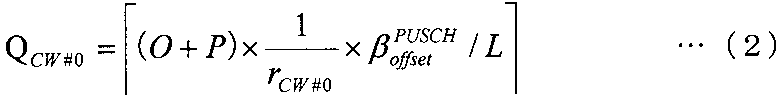
[通信システムの概要]
以下の説明では、後述する基地局100及び端末200を含む通信システムは、例えば、LTE-Aシステムであり、基地局100は、例えば、LTE-A基地局であり、端末200は、例えば、LTE-A端末である。また、この通信システムは、FDD(Frequency Division Duplex)システムを想定する。また、端末200(LTE-A端末)はNon-MIMO送信モード及びSU-MIMO送信モードの切替が可能な構成を備える。
図4は、本実施の形態に係る基地局100の構成を示すブロック図である。
図5は、本実施の形態に係る端末200の構成を示すブロック図である。端末200はLTE-A端末であり、データ信号(下り回線データ)を受信し、そのデータ信号に対するACK/NACK信号をPUCCH(Physical Uplink Control Channel)又はPUSCHを用いて基地局100へ送信する。また、端末200は、PDCCH(Physical Downlink Control Channel)で通知される指示情報に従って、CQIを基地局100へ送信する。
以上の構成を有する基地局100および端末200の動作について説明する。ここでは、主に、端末200のリソース量決定部204における制御情報(ACK/NACK又はCQI)の割当に必要なリソース量の決定方法の詳細について説明する。なお、以下の説明では、SU-MIMO送信を行う場合、すなわち、制御情報が配置された複数のCWを異なる複数のレイヤで送信する場合におけるリソース量の決定方法について説明する。
決定方法1では、リソース量決定部204は、制御情報が配置される2つのCWの符号化率のうちのより低い符号化率に基づいて、各レイヤで制御情報の割当に必要なリソース量を決定する。具体的には、リソース量決定部204は、次式(3)に従って、CW#0の符号化率及びCW#1の符号化率のうち、より低いCWの符号化率(符号化率rlowMCS)に基づいて、各レイヤで制御情報の割当に必要なリソース量QCW#0+CW#1を決定する。

決定方法2では、リソース量決定部204は、2つのCWの符号化率の逆数の平均値に基づいて、各レイヤにおける制御情報のリソース量を決定する。具体的には、リソース量決定部204は、次式(4)に従って、各レイヤにおける制御情報のリソース量QCW#0+CW#1を決定する。
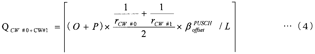
決定方法3では、リソース量決定部204は、2つのCWのうち一方のCWの符号化率の逆数、及び、基地局100から通知される補正係数に基づいて、各レイヤにおける制御情報のリソース量を決定する。具体的には、リソース量決定部204は、次式(5)に従って、各レイヤにおける制御情報のリソース量QCW#0+CW#1を決定する。
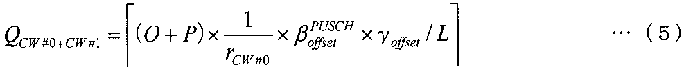
決定方法4において、2つのCWのうち一方のCWの符号化率(逆数)に基づいて算出される制御情報のリソース量に補正係数を乗算する点は決定方法3(式(5))と同様である。ただし、決定方法4では、補正係数の算出方法が決定方法3と異なる。


複数のレイヤで同一の制御情報が同一時間・同一周波数で送信される場合、つまり、Rank1送信の場合、複数のレイヤで送信される制御情報に割り当てられるリソース量は全てのレイヤで同一となる。


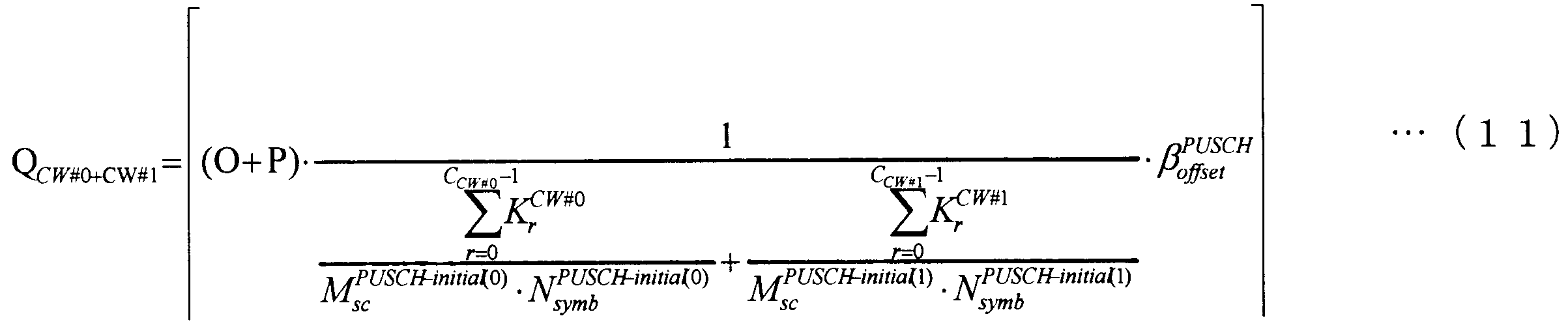


実施の形態1では、2つのCW(コードワード)の符号化率の内のより低い符号化率、又は、2つのCWの符号化率の逆数の平均値に基づいて制御情報のリソース量を決定した。これに対して、実施の形態2では、実施の形態1の処理に加え、データ信号と制御情報とに存在するレイヤ間干渉の違いを考慮して制御情報のリソース量を決定する。
以上の構成を有する基地局100および端末200の動作について説明する。
制御情報のレイヤ数又はRank数と、データ信号のレイヤ数又はRank数とが同一である場合、データ信号と制御情報との間では同一のレイヤ間干渉が発生する。例えば、制御情報が配置されるCW#0をレイヤ#0に割り当て、データ信号が配置されるCW#1をレイヤ#1に割り当てて空間多重する場合、データ信号と制御情報はRank2となり同程度のレイヤ間干渉となる。

実施の形態1では、初回送信時と再送時とでレイヤ数が同じになる場合を想定した。これに対して、実施の形態3では、実施の形態1の処理において、初回送信時と再送時とのレイヤ数の違いを考慮して制御情報のリソース量を決定する。
以上の構成を有する基地局100および端末200の動作について説明する。
決定方法1~6では、初回送信と再送時とでレイヤ数が同一である場合を想定した。また、初回送信時には制御情報のリソース量を、例えば式(9)(決定方法5)で設定することにより、制御情報に対して一定以上の受信品質(所要の受信品質)を満たすことができる。


(1)上記実施の形態におけるMIMO送信モードは、LTEで規定されるTransmission mode 3、 4、つまり2CWの送信がサポートされる送信モードとし、non-MIMO送信モードは、それ以外のTransmission mode、つまり1CWのみが送信される送信モードとしても良い。また、上記実施の形態では、複数のCWで送信するMIMO送信モード、および、1つのCWで送信するNon-MIMO送信モードを想定して説明した。詳細には、上述したように、MIMO送信モードでは信号が複数のレイヤ(または複数のRank)で送信され、Non-MIMOでは信号が1つのレイヤ(または1つのRank)で送信されることを想定して説明した。しかしながら、これに限定する必要はなく、MIMO送信モード(例えばSU-MIMO送信)では信号が複数のアンテナポートで送信され、Non-MIMOでは信号が1つのアンテナポートで送信されるとしてもよい。
200 端末
101 設定部
102,103 符号化・変調部
104,205 送信信号生成部
105,206 送信部
106,201 アンテナ
107,202 受信部
108,208 無線処理部
109,203 受信処理部
110 データ受信部
111 ACK/NACK・CQI受信部
204 リソース量決定部
207 送信処理部
Claims (10)
- 制御情報が配置された2つのコードワードを異なる複数のレイヤで送信する端末装置であって、
前記複数のレイヤそれぞれにおける前記制御情報のリソース量を決定する決定手段と、
前記リソース量を用いて変調された前記制御情報を、前記2つのコードワードに配置することにより、送信信号を生成する送信信号生成手段と、
を具備し、
前記決定手段は、前記2つのコードワードの符号化率の内のより低い符号化率、又は、前記2つのコードワードの符号化率の逆数の平均値に基づいて前記リソース量を決定する、
端末装置。 - 前記決定手段は、前記2つのコードワードのうち、第1のコードワードの符号化率rCW#0の逆数と第2のコードワードの符号化率rCW#1の逆数との平均を、前記平均値として用いて、式(1)に示す前記リソース量QCW#0+CW#1を決定する、
請求項1記載の端末装置。

- 前記決定手段は、前記2つのコードワードのうち、いずれか一方のコードワードの符号化率rCW#0の逆数に、補正係数γoffsetを乗算した乗算結果(γoffset/rCW#0)を、前記平均値として用いて、式(2)に示す前記リソース量QCW#0+CW#1を決定する、
請求項1記載の端末装置。

- 前記決定手段は、前記2つのコードワードの符号化率の差に応じて設定される前記補正係数γoffsetを前記符号化率rCW#0の逆数に乗算して得られる前記乗算結果(γoffset/rCW#0)を、前記平均値として用いて、前記式(2)に示す前記リソース量QCW#0+CW#1を決定する、
請求項3記載の端末装置。 - 前記決定手段は、式(3)に示す前記補正係数γoffsetを前記符号化率rCW#0の逆数に乗算して得られる前記乗算結果(γoffset/rCW#0)を、前記平均値として用いて、前記式(1)に示す前記リソース量QCW#0+CW#1を決定する、
請求項3記載の端末装置。

- 前記決定手段は、式(4)に示す前記平均値を用いて、式(5)に示す前記リソース量QCW#0+CW#1を決定する、
請求項1記載の端末装置。


- 前記決定手段は、前記複数のレイヤのそれぞれに割り当てられるコードワードの符号化率の平均値((rCW#0×LCW#0+rCW#1×LCW#1)/(LCW#0+LCW#1))の逆数を、前記平均値として用いて、式(6)に示す前記リソース量QCW#0+CW#1を決定する、
請求項1記載の端末装置。

- 前記決定手段は、再送時に各コードワードが配置されるレイヤ数に応じて、式(7)に示す、前記再送時における前記リソース量QCW#0+CW#1を再設定する、
請求項1記載の端末装置。

- 前記決定手段は、初回送信時に各コードワードが配置されたレイヤ数と、再送時に各コードワードが配置されるレイヤ数との比に基づいて、式(8)に示す、前記再送時における前記リソース量QCW#0+CW#1を決定する、
請求項1記載の端末装置。

- 制御情報が配置された2つのコードワードが送信される異なる複数のレイヤそれぞれにおける、前記制御情報のリソース量を決定し、
前記リソース量を用いて変調された前記制御情報を、前記2つのコードワードに配置することにより、送信信号を生成する通信方法であって、
前記2つのコードワードの符号化率のうちのより低い符号化率、又は、前記2つのコードワードの符号化率の逆数の平均値に基づいて前記リソース量を決定する、
通信方法。
Priority Applications (27)
| Application Number | Priority Date | Filing Date | Title |
|---|---|---|---|
| AU2011270584A AU2011270584B2 (en) | 2010-06-21 | 2011-06-07 | Terminal apparatus and communication method thereof |
| EP11797776.9A EP2584827B1 (en) | 2010-06-21 | 2011-06-07 | Terminal apparatus and communication method thereof |
| JP2012521285A JP5715129B2 (ja) | 2010-06-21 | 2011-06-07 | 端末装置及びその通信方法 |
| BR112012031268-5A BR112012031268B1 (pt) | 2010-06-21 | 2011-06-07 | aparelho terminal e método de comunicação do mesmo |
| SI201131486T SI2584827T1 (en) | 2010-06-21 | 2011-06-07 | Terminal apparatus and communication procedure thereof |
| SG2012090320A SG186233A1 (en) | 2010-06-21 | 2011-06-07 | Terminal apparatus and communication method thereof |
| LTEP11797776.9T LT2584827T (lt) | 2010-06-21 | 2011-06-07 | Terminalo įranga ir jos ryšio būdas |
| EP18152437.2A EP3340675B1 (en) | 2010-06-21 | 2011-06-07 | Terminal apparatus and communication method thereof |
| ES11797776.9T ES2668811T3 (es) | 2010-06-21 | 2011-06-07 | Aparato terminal y método de comunicación del mismo |
| KR1020127031949A KR101747480B1 (ko) | 2010-06-21 | 2011-06-07 | 단말 장치 및 그 통신 방법 |
| EP19216981.1A EP3694250B1 (en) | 2010-06-21 | 2011-06-07 | Apparatus and communication method thereof |
| US13/699,557 US8830911B2 (en) | 2010-06-21 | 2011-06-07 | Terminal apparatus and communication method thereof |
| RS20180694A RS57335B1 (sr) | 2010-06-21 | 2011-06-07 | Terminalni uređaji i komunikaciona metoda koja se pri tome koristi |
| CN201180026631.5A CN102934482B (zh) | 2010-06-21 | 2011-06-07 | 终端装置以及其通信方法 |
| DK11797776.9T DK2584827T3 (en) | 2010-06-21 | 2011-06-07 | TERMINAL DEVICE AND COMMUNICATION PROCEDURE |
| KR1020177015368A KR101833695B1 (ko) | 2010-06-21 | 2011-06-07 | 단말 장치, 기지국 장치, 송신 방법, 수신 방법 및 집적 회로 |
| RU2012152641/07A RU2556877C2 (ru) | 2010-06-21 | 2011-06-07 | Терминальное устройство и его способ связи |
| PL11797776T PL2584827T3 (pl) | 2010-06-21 | 2011-06-07 | Urządzenie końcowe i wykorzystywany w nim sposób komunikowania się |
| US14/447,259 US9509477B2 (en) | 2010-06-21 | 2014-07-30 | Terminal apparatus and communication method thereof |
| US15/294,301 US9755805B2 (en) | 2010-06-21 | 2016-10-14 | Communication apparatus and communication method thereof |
| US15/664,689 US10057035B2 (en) | 2010-06-21 | 2017-07-31 | Communication apparatus and communication method thereof |
| CY20181100562T CY1120539T1 (el) | 2010-06-21 | 2018-05-25 | Τελικη συσκευη και μεθοδος επικοινωνιας για αυτην |
| HRP20180949TT HRP20180949T1 (hr) | 2010-06-21 | 2018-06-19 | Terminalni uređaj i postupak komunikacije istog |
| US16/040,304 US10419189B2 (en) | 2010-06-21 | 2018-07-19 | Communication apparatus and communication method thereof |
| US16/532,242 US10826666B2 (en) | 2010-06-21 | 2019-08-05 | Communication apparatus and communication method thereof |
| US17/031,079 US11533147B2 (en) | 2010-06-21 | 2020-09-24 | Communication apparatus and communication method thereof |
| US18/054,852 US11949624B2 (en) | 2010-06-21 | 2022-11-11 | Communication apparatus and communication method thereof |
Applications Claiming Priority (4)
| Application Number | Priority Date | Filing Date | Title |
|---|---|---|---|
| JP2010140751 | 2010-06-21 | ||
| JP2010-140751 | 2010-06-21 | ||
| JP2010-221392 | 2010-09-30 | ||
| JP2010221392 | 2010-09-30 |
Related Child Applications (2)
| Application Number | Title | Priority Date | Filing Date |
|---|---|---|---|
| US13/699,557 A-371-Of-International US8830911B2 (en) | 2010-06-21 | 2011-06-07 | Terminal apparatus and communication method thereof |
| US14/447,259 Continuation US9509477B2 (en) | 2010-06-21 | 2014-07-30 | Terminal apparatus and communication method thereof |
Publications (1)
| Publication Number | Publication Date |
|---|---|
| WO2011161887A1 true WO2011161887A1 (ja) | 2011-12-29 |
Family
ID=45371094
Family Applications (1)
| Application Number | Title | Priority Date | Filing Date |
|---|---|---|---|
| PCT/JP2011/003198 WO2011161887A1 (ja) | 2010-06-21 | 2011-06-07 | 端末装置及びその通信方法 |
Country Status (21)
| Country | Link |
|---|---|
| US (8) | US8830911B2 (ja) |
| EP (3) | EP3694250B1 (ja) |
| JP (2) | JP5715129B2 (ja) |
| KR (2) | KR101747480B1 (ja) |
| CN (2) | CN105554814B (ja) |
| AU (1) | AU2011270584B2 (ja) |
| BR (1) | BR112012031268B1 (ja) |
| CY (1) | CY1120539T1 (ja) |
| DK (1) | DK2584827T3 (ja) |
| ES (1) | ES2668811T3 (ja) |
| HR (1) | HRP20180949T1 (ja) |
| HU (1) | HUE038240T2 (ja) |
| LT (1) | LT2584827T (ja) |
| PL (1) | PL2584827T3 (ja) |
| PT (1) | PT2584827T (ja) |
| RS (1) | RS57335B1 (ja) |
| RU (2) | RU2556877C2 (ja) |
| SG (2) | SG186233A1 (ja) |
| SI (1) | SI2584827T1 (ja) |
| TW (2) | TWI584608B (ja) |
| WO (1) | WO2011161887A1 (ja) |
Cited By (4)
| Publication number | Priority date | Publication date | Assignee | Title |
|---|---|---|---|---|
| JP5482898B2 (ja) * | 2010-07-09 | 2014-05-07 | 日本電気株式会社 | 通信装置およびリソース導出方法 |
| JPWO2015008830A1 (ja) * | 2013-07-19 | 2017-03-02 | シャープ株式会社 | 端末装置、基地局装置、集積回路、および無線通信方法 |
| WO2018163431A1 (ja) * | 2017-03-10 | 2018-09-13 | 株式会社Nttドコモ | ユーザ端末及び無線通信方法 |
| WO2019187146A1 (ja) * | 2018-03-30 | 2019-10-03 | 富士通株式会社 | 基地局、無線通信端末、無線通信システム、及び無線通信方法 |
Families Citing this family (13)
| Publication number | Priority date | Publication date | Assignee | Title |
|---|---|---|---|---|
| US8848557B2 (en) * | 2010-08-25 | 2014-09-30 | Samsung Electronics Co., Ltd. | Multiplexing of control and data in UL MIMO system based on SC-FDM |
| CN103477583B (zh) * | 2011-04-19 | 2016-11-09 | 太阳专利托管公司 | 预编码方法、预编码装置 |
| WO2017026972A1 (en) * | 2015-08-07 | 2017-02-16 | Intel IP Corporation | Uci for carrier aggregation |
| MY191869A (en) | 2015-12-01 | 2022-07-18 | Ericsson Telefon Ab L M | Predictive acknowledgment feedback mechanism |
| CN109417448B (zh) | 2016-05-11 | 2021-08-20 | Idac控股公司 | 支持在同一信道内使用混合参数配置的物理(phy)层方案 |
| WO2017193382A1 (zh) * | 2016-05-13 | 2017-11-16 | 华为技术有限公司 | 控制信息发送、接收方法和设备 |
| KR20190116293A (ko) * | 2017-02-06 | 2019-10-14 | 모토로라 모빌리티 엘엘씨 | 짧은 pdcch 동작을 위한 방법 및 장치 |
| CN110476386B (zh) * | 2017-03-20 | 2022-03-15 | Lg电子株式会社 | 在下一代通信系统中映射码字和层的方法及其装置 |
| CA3032798C (en) | 2017-03-25 | 2022-07-19 | Lg Electronics Inc. | Method and device for receiving ptrs for cancelling phase noise in wireless communication system |
| CN109644094B (zh) | 2017-08-04 | 2020-07-31 | Oppo广东移动通信有限公司 | 信息处理方法、通信设备和计算机存储介质 |
| US11601223B2 (en) * | 2017-08-18 | 2023-03-07 | Qualcomm Incorporated | Systems and methods for HARQ transmission and retransmission using multiple code words |
| US11516834B2 (en) * | 2017-11-13 | 2022-11-29 | Qualcomm Incorporated | Uplink control information transmission |
| WO2019097696A1 (ja) * | 2017-11-17 | 2019-05-23 | 株式会社Nttドコモ | ユーザ端末及び無線通信方法 |
Citations (4)
| Publication number | Priority date | Publication date | Assignee | Title |
|---|---|---|---|---|
| JP2009189007A (ja) * | 2008-02-04 | 2009-08-20 | Samsung Electronics Co Ltd | 通信システムにおける制御及びデータ多重化 |
| WO2010064407A1 (ja) * | 2008-12-02 | 2010-06-10 | パナソニック株式会社 | 符号化率設定方法及び無線通信装置 |
| JP2010140751A (ja) | 2008-12-11 | 2010-06-24 | Nsk Ltd | 発電素子 |
| JP2010221392A (ja) | 2009-02-25 | 2010-10-07 | Kyocera Corp | 光通信用スリーブの内径研磨ピン並びにこれを用いた内径研磨装置および製造方法 |
Family Cites Families (26)
| Publication number | Priority date | Publication date | Assignee | Title |
|---|---|---|---|---|
| US7130587B2 (en) * | 2001-08-22 | 2006-10-31 | National Institute of Information and Communications Technology Incorporated, Administrative Agency | Communication quality estimation method, communication quality estimation apparatus, and communication system |
| JP4675167B2 (ja) * | 2005-06-14 | 2011-04-20 | 株式会社エヌ・ティ・ティ・ドコモ | チャネル割り当て方法、無線通信システム、基地局装置、ユーザ端末 |
| JP4668843B2 (ja) | 2006-05-26 | 2011-04-13 | 富士通株式会社 | 無線基地局受信装置及びプログラム |
| CN101132608A (zh) * | 2006-08-22 | 2008-02-27 | 北京三星通信技术研究有限公司 | 指示信道资源分配信息的设备和方法 |
| AU2007316403B2 (en) | 2006-11-06 | 2011-02-03 | Qualcomm Incorporated | MIMO transmission with layer permutation in a wireless communication system |
| EP1944896A1 (en) | 2007-01-09 | 2008-07-16 | Matsushita Electric Industrial Co., Ltd. | Configuration of control channels in a mobile communication system |
| JP4671982B2 (ja) * | 2007-01-09 | 2011-04-20 | 株式会社エヌ・ティ・ティ・ドコモ | 基地局、送信方法及び移動通信システム |
| CN101595763B (zh) * | 2007-01-31 | 2012-01-25 | 富士通株式会社 | 无线通信控制方法、无线基站和无线终端 |
| CN101296207B (zh) * | 2007-04-28 | 2011-08-10 | 华为技术有限公司 | 控制信令的传输方法、网络侧设备以及终端 |
| US8243673B2 (en) | 2007-06-15 | 2012-08-14 | Panasonic Corporation | Radio communication apparatus, radio communication system, and radio communication method |
| ES2377540T5 (es) * | 2008-02-06 | 2018-09-25 | Telefonaktiebolaget Lm Ericsson (Publ) | Métodos y dispositivos relativos a asignaciones de enlace descendente |
| RU2480963C2 (ru) * | 2008-04-28 | 2013-04-27 | Нокиа Сименс Нетуоркс Ой | Способ и устройство для связывания схемы модуляции и кодирования с объемом ресурсов |
| KR101591086B1 (ko) * | 2008-05-21 | 2016-02-03 | 엘지전자 주식회사 | 다중 안테나 시스템에서 harq 수행 방법 |
| KR100925444B1 (ko) * | 2008-05-27 | 2009-11-06 | 엘지전자 주식회사 | 상향링크 채널을 통해 데이터와 제어 정보를 포함하는 상향링크 신호를 전송하는 방법 |
| WO2010000743A2 (en) * | 2008-06-30 | 2010-01-07 | Nokia Siemens Networks Oy | Selecting between normal and virtual dual layer ack/nack |
| ES2760570T3 (es) * | 2008-07-22 | 2020-05-14 | Lg Electronics Inc | Método para asignar un PHICH y generar una señal de referencia en un sistema que usa MIMO de usuario único basado en múltiples palabras de código en una transmisión de enlace ascendente |
| US8625554B2 (en) * | 2009-01-30 | 2014-01-07 | Samsung Electronics Co., Ltd. | System and method for uplink data and control signal transmission in MIMO wireless systems |
| JP5077485B2 (ja) * | 2009-04-28 | 2012-11-21 | 日本電気株式会社 | 基地局装置、無線通信システム、基地局の制御方法、および無線通信システムの制御方法 |
| CN101695017A (zh) * | 2009-10-27 | 2010-04-14 | 中兴通讯股份有限公司 | 物理上行共享信道传输上行控制信令的方法与装置 |
| CN101702631A (zh) * | 2009-11-04 | 2010-05-05 | 中兴通讯股份有限公司 | 上行控制信令传输方法和装置 |
| US8958380B2 (en) * | 2010-03-22 | 2015-02-17 | Lg Electronics Inc. | Method and device for transmitting control information |
| US9100155B2 (en) * | 2010-05-03 | 2015-08-04 | Qualcomm Incorporated | Method and apparatus for control and data multiplexing in wireless communication |
| US8989156B2 (en) * | 2010-06-18 | 2015-03-24 | Sharp Kabushiki Kaisha | Selecting a codeword and determining a symbol length for uplink control information |
| KR101317975B1 (ko) * | 2010-08-13 | 2013-10-14 | 제트티이 (유에스에이) 잉크. | 물리적 업링크 공유 채널상에서 업링크 제어 정보를 다중화하기 위한 방법 |
| US8848557B2 (en) * | 2010-08-25 | 2014-09-30 | Samsung Electronics Co., Ltd. | Multiplexing of control and data in UL MIMO system based on SC-FDM |
| US8990656B2 (en) * | 2010-11-17 | 2015-03-24 | Lg Electronics Inc. | Method for transmitting uplink control information in a wireless access system and terminal for same |
-
2011
- 2011-06-07 KR KR1020127031949A patent/KR101747480B1/ko active IP Right Grant
- 2011-06-07 PL PL11797776T patent/PL2584827T3/pl unknown
- 2011-06-07 EP EP19216981.1A patent/EP3694250B1/en active Active
- 2011-06-07 RU RU2012152641/07A patent/RU2556877C2/ru active
- 2011-06-07 PT PT117977769T patent/PT2584827T/pt unknown
- 2011-06-07 HU HUE11797776A patent/HUE038240T2/hu unknown
- 2011-06-07 JP JP2012521285A patent/JP5715129B2/ja active Active
- 2011-06-07 LT LTEP11797776.9T patent/LT2584827T/lt unknown
- 2011-06-07 EP EP11797776.9A patent/EP2584827B1/en active Active
- 2011-06-07 DK DK11797776.9T patent/DK2584827T3/en active
- 2011-06-07 US US13/699,557 patent/US8830911B2/en active Active
- 2011-06-07 CN CN201511009969.6A patent/CN105554814B/zh active Active
- 2011-06-07 SG SG2012090320A patent/SG186233A1/en unknown
- 2011-06-07 EP EP18152437.2A patent/EP3340675B1/en active Active
- 2011-06-07 CN CN201180026631.5A patent/CN102934482B/zh active Active
- 2011-06-07 AU AU2011270584A patent/AU2011270584B2/en active Active
- 2011-06-07 SI SI201131486T patent/SI2584827T1/en unknown
- 2011-06-07 SG SG10201404644VA patent/SG10201404644VA/en unknown
- 2011-06-07 ES ES11797776.9T patent/ES2668811T3/es active Active
- 2011-06-07 BR BR112012031268-5A patent/BR112012031268B1/pt active IP Right Grant
- 2011-06-07 WO PCT/JP2011/003198 patent/WO2011161887A1/ja active Application Filing
- 2011-06-07 RS RS20180694A patent/RS57335B1/sr unknown
- 2011-06-07 KR KR1020177015368A patent/KR101833695B1/ko active IP Right Grant
- 2011-06-20 TW TW104137384A patent/TWI584608B/zh active
- 2011-06-20 TW TW100121401A patent/TWI514803B/zh active
-
2014
- 2014-07-30 US US14/447,259 patent/US9509477B2/en active Active
-
2015
- 2015-03-11 JP JP2015048385A patent/JP5883523B2/ja active Active
- 2015-05-28 RU RU2015120327A patent/RU2659232C2/ru active
-
2016
- 2016-10-14 US US15/294,301 patent/US9755805B2/en active Active
-
2017
- 2017-07-31 US US15/664,689 patent/US10057035B2/en active Active
-
2018
- 2018-05-25 CY CY20181100562T patent/CY1120539T1/el unknown
- 2018-06-19 HR HRP20180949TT patent/HRP20180949T1/hr unknown
- 2018-07-19 US US16/040,304 patent/US10419189B2/en active Active
-
2019
- 2019-08-05 US US16/532,242 patent/US10826666B2/en active Active
-
2020
- 2020-09-24 US US17/031,079 patent/US11533147B2/en active Active
-
2022
- 2022-11-11 US US18/054,852 patent/US11949624B2/en active Active
Patent Citations (4)
| Publication number | Priority date | Publication date | Assignee | Title |
|---|---|---|---|---|
| JP2009189007A (ja) * | 2008-02-04 | 2009-08-20 | Samsung Electronics Co Ltd | 通信システムにおける制御及びデータ多重化 |
| WO2010064407A1 (ja) * | 2008-12-02 | 2010-06-10 | パナソニック株式会社 | 符号化率設定方法及び無線通信装置 |
| JP2010140751A (ja) | 2008-12-11 | 2010-06-24 | Nsk Ltd | 発電素子 |
| JP2010221392A (ja) | 2009-02-25 | 2010-10-07 | Kyocera Corp | 光通信用スリーブの内径研磨ピン並びにこれを用いた内径研磨装置および製造方法 |
Non-Patent Citations (2)
| Title |
|---|
| 3GPP TS36.212 V9.2.0, 3GPP, 14 June 2010 (2010-06-14), pages 20 - 34, XP050441487 * |
| See also references of EP2584827A4 |
Cited By (6)
| Publication number | Priority date | Publication date | Assignee | Title |
|---|---|---|---|---|
| JP5482898B2 (ja) * | 2010-07-09 | 2014-05-07 | 日本電気株式会社 | 通信装置およびリソース導出方法 |
| US9312932B2 (en) | 2010-07-09 | 2016-04-12 | Nec Corporation | Communication apparatus and resource derivation method |
| JPWO2015008830A1 (ja) * | 2013-07-19 | 2017-03-02 | シャープ株式会社 | 端末装置、基地局装置、集積回路、および無線通信方法 |
| WO2018163431A1 (ja) * | 2017-03-10 | 2018-09-13 | 株式会社Nttドコモ | ユーザ端末及び無線通信方法 |
| JPWO2018163431A1 (ja) * | 2017-03-10 | 2020-01-09 | 株式会社Nttドコモ | ユーザ端末及び無線通信方法 |
| WO2019187146A1 (ja) * | 2018-03-30 | 2019-10-03 | 富士通株式会社 | 基地局、無線通信端末、無線通信システム、及び無線通信方法 |
Also Published As
Similar Documents
| Publication | Publication Date | Title |
|---|---|---|
| JP5883523B2 (ja) | 端末装置、基地局装置、送信方法、受信方法及び集積回路 | |
| US9036739B2 (en) | Multiplexing control and data information from a user equipment in MIMO transmission mode | |
| US20100278109A1 (en) | Multiplexing large payloads of control information from user equipments | |
| JP5957743B2 (ja) | 端末装置、送信方法及び集積回路 | |
| KR101674960B1 (ko) | 분산 안테나 기술을 지원하는 무선 접속 시스템에서 제한된 피드백을 최적화하기 위한 방법 및 장치 |
Legal Events
| Date | Code | Title | Description |
|---|---|---|---|
| WWE | Wipo information: entry into national phase |
Ref document number: 201180026631.5 Country of ref document: CN |
|
| 121 | Ep: the epo has been informed by wipo that ep was designated in this application |
Ref document number: 11797776 Country of ref document: EP Kind code of ref document: A1 |
|
| WWE | Wipo information: entry into national phase |
Ref document number: 2012521285 Country of ref document: JP |
|
| WWE | Wipo information: entry into national phase |
Ref document number: 13699557 Country of ref document: US Ref document number: 2601/MUMNP/2012 Country of ref document: IN |
|
| ENP | Entry into the national phase |
Ref document number: 2011270584 Country of ref document: AU Date of ref document: 20110607 Kind code of ref document: A Ref document number: 20127031949 Country of ref document: KR Kind code of ref document: A |
|
| WWE | Wipo information: entry into national phase |
Ref document number: 2011797776 Country of ref document: EP |
|
| NENP | Non-entry into the national phase |
Ref country code: DE |
|
| ENP | Entry into the national phase |
Ref document number: 2012152641 Country of ref document: RU Kind code of ref document: A |
|
| REG | Reference to national code |
Ref country code: BR Ref legal event code: B01A Ref document number: 112012031268 Country of ref document: BR |
|
| ENP | Entry into the national phase |
Ref document number: 112012031268 Country of ref document: BR Kind code of ref document: A2 Effective date: 20121207 |