WO2011155431A1 - 磁石フィルタ及びそれを用いた不純物回収方法 - Google Patents
磁石フィルタ及びそれを用いた不純物回収方法 Download PDFInfo
- Publication number
- WO2011155431A1 WO2011155431A1 PCT/JP2011/062913 JP2011062913W WO2011155431A1 WO 2011155431 A1 WO2011155431 A1 WO 2011155431A1 JP 2011062913 W JP2011062913 W JP 2011062913W WO 2011155431 A1 WO2011155431 A1 WO 2011155431A1
- Authority
- WO
- WIPO (PCT)
- Prior art keywords
- magnet
- layer
- layers
- filter
- nonwoven fabric
- Prior art date
- Legal status (The legal status is an assumption and is not a legal conclusion. Google has not performed a legal analysis and makes no representation as to the accuracy of the status listed.)
- Ceased
Links
Images



Classifications
-
- B—PERFORMING OPERATIONS; TRANSPORTING
- B03—SEPARATION OF SOLID MATERIALS USING LIQUIDS OR USING PNEUMATIC TABLES OR JIGS; MAGNETIC OR ELECTROSTATIC SEPARATION OF SOLID MATERIALS FROM SOLID MATERIALS OR FLUIDS; SEPARATION BY HIGH-VOLTAGE ELECTRIC FIELDS
- B03C—MAGNETIC OR ELECTROSTATIC SEPARATION OF SOLID MATERIALS FROM SOLID MATERIALS OR FLUIDS; SEPARATION BY HIGH-VOLTAGE ELECTRIC FIELDS
- B03C1/00—Magnetic separation
- B03C1/02—Magnetic separation acting directly on the substance being separated
- B03C1/28—Magnetic plugs and dipsticks
- B03C1/286—Magnetic plugs and dipsticks disposed at the inner circumference of a recipient, e.g. magnetic drain bolt
-
- B—PERFORMING OPERATIONS; TRANSPORTING
- B03—SEPARATION OF SOLID MATERIALS USING LIQUIDS OR USING PNEUMATIC TABLES OR JIGS; MAGNETIC OR ELECTROSTATIC SEPARATION OF SOLID MATERIALS FROM SOLID MATERIALS OR FLUIDS; SEPARATION BY HIGH-VOLTAGE ELECTRIC FIELDS
- B03C—MAGNETIC OR ELECTROSTATIC SEPARATION OF SOLID MATERIALS FROM SOLID MATERIALS OR FLUIDS; SEPARATION BY HIGH-VOLTAGE ELECTRIC FIELDS
- B03C1/00—Magnetic separation
- B03C1/02—Magnetic separation acting directly on the substance being separated
- B03C1/025—High gradient magnetic separators
- B03C1/031—Component parts; Auxiliary operations
- B03C1/033—Component parts; Auxiliary operations characterised by the magnetic circuit
- B03C1/0332—Component parts; Auxiliary operations characterised by the magnetic circuit using permanent magnets
-
- B—PERFORMING OPERATIONS; TRANSPORTING
- B01—PHYSICAL OR CHEMICAL PROCESSES OR APPARATUS IN GENERAL
- B01D—SEPARATION
- B01D2239/00—Aspects relating to filtering material for liquid or gaseous fluids
- B01D2239/04—Additives and treatments of the filtering material
-
- B—PERFORMING OPERATIONS; TRANSPORTING
- B01—PHYSICAL OR CHEMICAL PROCESSES OR APPARATUS IN GENERAL
- B01D—SEPARATION
- B01D2239/00—Aspects relating to filtering material for liquid or gaseous fluids
- B01D2239/06—Filter cloth, e.g. knitted, woven non-woven; self-supported material
- B01D2239/0604—Arrangement of the fibres in the filtering material
- B01D2239/0618—Non-woven
-
- B—PERFORMING OPERATIONS; TRANSPORTING
- B03—SEPARATION OF SOLID MATERIALS USING LIQUIDS OR USING PNEUMATIC TABLES OR JIGS; MAGNETIC OR ELECTROSTATIC SEPARATION OF SOLID MATERIALS FROM SOLID MATERIALS OR FLUIDS; SEPARATION BY HIGH-VOLTAGE ELECTRIC FIELDS
- B03C—MAGNETIC OR ELECTROSTATIC SEPARATION OF SOLID MATERIALS FROM SOLID MATERIALS OR FLUIDS; SEPARATION BY HIGH-VOLTAGE ELECTRIC FIELDS
- B03C2201/00—Details of magnetic or electrostatic separation
- B03C2201/18—Magnetic separation whereby the particles are suspended in a liquid
Definitions
- the present invention relates to a magnet filter for recovering magnetic impurities contained in a fluid and an impurity recovery method using the magnet filter.
- Patent Document 1 discloses a filter characterized by arranging a filter and a magnet in a fluid flow path. And according to this, it describes that the ultrafine particles etc. which could not be removed with the conventional filter can be removed.
- Patent Document 2 discloses a filter having a permanent magnet fiber that does not require an external magnetic field as at least a part of its constituent elements. And it is described that according to this, the filter which can remove magnetic particles, such as iron powder contained in a fluid, simply and efficiently can be provided.
- Patent Document 3 in an oil filter device provided with a filter paper folded into a waveform in which peaks and valleys are alternately continued inside a casing, permanent magnets are inserted into the valleys formed on the filter paper.
- An oil filter device characterized by being provided is disclosed. And according to this, it describes that the magnetic metal powder in lubricating oil can be removed efficiently.
- this invention makes it a subject to provide the magnetic filter which can collect
- the inventor uses a magnet filter configured to sandwich a nonwoven fabric layer with a magnet layer in which a plurality of holes penetrating in the thickness direction is used, so that the magnet layer against magnetic impurities in the fluid
- the magnetic material impurities in the fluid can be efficiently recovered by passing the plurality of holes and forming a flow path by the nonwoven fabric layer provided between the magnet layers to retain the magnetic material impurities in the fluid. I found it.
- the present invention completed on the basis of the above knowledge is provided in one aspect between at least a pair of flexible magnet layers each having a plurality of holes penetrating in the thickness direction, and the pair of magnet layers. And a non-woven fabric layer.
- the hole has a circular cross-sectional shape perpendicular to the thickness direction of the magnet layer.
- the holes are arranged at substantially equal intervals.
- the plurality of holes of the magnet layer are formed at positions that do not overlap with the plurality of holes of the magnet layer facing each other.
- the total area of the holes is not more than half of the total area of the magnet layer.
- the magnet layer is formed of an anisotropic magnetized double-sided magnet.
- the at least one pair of magnet layers are each formed in a cylindrical shape and provided on one outer peripheral side or inner peripheral side, and the nonwoven fabric layer is It is formed in a cylindrical shape and is provided between the pair of magnet layers.
- the at least one pair of cylindrical magnet layers and a cylindrical nonwoven fabric layer provided between the pair of magnet layers constitute a unit filter.
- the unit filter is provided so as to overlap in a direction perpendicular to the thickness direction of the cylindrical magnet layer via a nonwoven fabric layer.
- the thickness of the nonwoven fabric layer provided between the pair of magnet layers is equal to or less than the thickness of the magnet layer.
- the present invention is a method for recovering the magnetic impurities from a fluid containing the magnetic impurities using the magnet filter according to the present invention.
- the present invention is a combination of a magnet layer that forms a plurality of holes penetrating in the thickness direction and generates a magnetic field around the plurality of holes, and a nonwoven fabric layer that has fine holes and serves as a fluid flow path. is there.
- a magnet layer that forms a plurality of holes penetrating in the thickness direction and generates a magnetic field around the plurality of holes
- a nonwoven fabric layer that has fine holes and serves as a fluid flow path.
- FIG. 1 (Embodiment 1) (Configuration of the magnet filter 10)
- FIG. 2 the schematic diagram of each structural member of the magnet filter 10 which concerns on Embodiment 1 of this invention is shown.
- FIG. 2 sectional drawing of the magnetic filter 10 which concerns on Embodiment 1 of this invention is shown.
- the magnet filter 10 includes at least a pair of flexible magnet layers (11a and 11b, 11b and 11c, 11c and 11d, 11d and 11e), and nonwoven fabric layers 12a and 12a ′ provided between the pair of magnet layers. 12b, 12b ′, 12c, 12c ′, 12d, and 12d ′.
- the magnet layers 11a, 11b, 11c, 11d, and 11e are formed of a flexible material, for example, a bonded magnet formed by mixing magnetic powder with a binder material such as rubber or plastic.
- the magnet layers 11a, 11b, 11c, 11d, and 11e may be anisotropically magnetized or isotropically magnetized, and may be single-sided magnetized or double-sided magnetized. It is preferably formed of an anisotropic magnetized double-sided magnet.
- Anisotropic magnetism has a stronger attracting force than isotropic magnetism, and double-sided magnetism forms a magnetic field in a larger range than single-sided magnetism, so if an anisotropic magnetized double-sided magnet is used, more impurities can be recovered.
- the magnet layers 11a, 11b, 11c, 11d, and 11e are formed in a disk shape having a predetermined thickness.
- the shape of the magnet layers 11a, 11b, 11c, 11d, and 11e is not limited thereto, and may be formed in a polygonal plate shape such as a triangle or a quadrangle.
- a plurality of holes 13a, 13b, 13c, 13d, and 13e penetrating in the thickness direction are formed in the magnet layers 11a, 11b, 11c, 11d, and 11e.
- the plurality of holes 13a, 13b, 13c, 13d, and 13e of the magnet layers 11a, 11b, 11c, 11d, and 11e are each formed in a columnar shape.
- the plurality of holes 13a, 13b, 13c, 13d, and 13e are not limited thereto, and may be formed in a prismatic shape such as a triangular prism or a quadrangular prism.
- the plurality of holes 13a, 13b, 13c, 13d, and 13e may be regularly arranged or irregularly arranged. Further, the plurality of holes 13a, 13b, 13c, 13d, and 13e may be arranged at substantially equal intervals.
- the total area of the plurality of holes 13a, 13b, 13c, 13d, and 13e is preferably less than or equal to half of the total area of the magnet layer.
- the nonwoven fabric layers 12a, 12a ′, 12b, 12b ′, 12c, 12c ′, 12d, 12d ′ are made of fibers by physical / chemical means (appropriate heat, adhesive, etc.) or mechanical means (high pressure water flow, etc.). It is a cloth-like sheet formed by tangling or adhering fibers, and has fine holes.
- the nonwoven fabric layers 12a, 12a ', 12b, 12b', 12c, 12c ', 12d, 12d' are formed in a shape corresponding to the magnet layers 11a, 11b, 11c, 11d, 11e.
- the nonwoven fabric layers 12a, 12a ′, 12b, 12b ′, 12c, 12c ′, 12d, and 12d ′ are formed in a disk shape corresponding to the magnet layers 11a, 11b, 11c, 11d, and 11e.
- the material of the nonwoven fabric layers 12a, 12a ′, 12b, 12b ′, 12c, 12c ′, 12d, 12d ′ is not particularly limited.
- cotton, wool, pulp, polypropylene fiber, polyethylene fiber, nylon fiber, vinylon fiber, polyester A fiber, a viscose rayon fiber, or a cupra rayon fiber may be used, and two or more of these may be included.
- the minimum structural unit of the magnet filter 10 according to Embodiment 1 is a total of three layers including a pair of magnet layers (for example, 11a and 11b) and a nonwoven fabric layer (for example, 12a) provided therebetween.
- the magnetic filter 10 has a five-layer structure in which a non-woven fabric layer (for example, 12b) and a magnet layer (for example, 11c) are provided in this order on the outside of the magnet layer (for example, 11b) in addition to the three layers that are the minimum constituent units. Further, a non-woven fabric layer (for example, 12c) and a magnet layer (for example, 11d) may be newly provided in this order on the outside of the magnet layer (for example, 11c) to form a seven-layer structure.
- the nonwoven fabric layer provided between the pair of magnet layers may be two layers.
- the magnet filter 10 shown in FIG. 1 is provided with two nonwoven fabric layers (12a and 12a ′, 12b and 12b ′) between a pair of magnet layers (11a and 11b, 11b and 11c), and a total of seven layers.
- the magnet filter 10 shown in FIG. 2 has a 13-layer structure. Any number of non-woven fabric layers may be provided as described above. However, if the total thickness is too large, the magnetic force from the magnet layer is difficult to reach and it is difficult to collect magnetic impurities.
- the magnetic force from the magnet layer is easy to reach, and the total thickness of the nonwoven fabric layer is the thickness of one magnet layer from the viewpoint of recovering impurities well. It is preferable that:
- the plurality of holes 13a, 13b, 13c, 13d, and 13e of the magnet layers 11a, 11b, 11c, 11d, and 11e constituting the magnet filter 10 are formed at positions that do not overlap with the plurality of holes of the opposing magnet layers, respectively. Is preferred.
- the positions where the plurality of holes 13 a, 13 b, 13 c, 13 d, and 13 e of the magnet layers 11 a, 11 b, 11 c, 11 d, and 11 e overlap with the plurality of holes of the opposing magnet layers, respectively.
- the nonwoven fabric layers 12a, 12a ′, 12b, 12b ′, 12c, 12c ′, 12d Move in 12d '.
- the time for which the fluid 14 stays in the nonwoven fabric layers 12a, 12a ', 12b, 12b', 12c, 12c ', 12d, and 12d' is lengthened, and impurities can be recovered more favorably.
- the magnet filter 10 is installed in a housing (not shown), and includes a magnetic substance such as metal powder as impurities in a state where a predetermined pressure is applied to the housing using, for example, a pressure regulator (not shown).
- the fluid 14 is supplied. As shown in FIG. 2, the supplied fluid 14 enters the magnet filter 10 from the magnet layer 11 a side that is the outermost layer of the magnet filter 10.
- the fluid 14 passes through the plurality of holes 13a of the magnet layer 11a which is the outermost layer, and soaks into the adjacent nonwoven fabric layers 12a and 12a ′.
- the fluid 14 soaked into the nonwoven fabric layers 12a and 12a ' The inside of the nonwoven fabric layers 12a and 12a ′ is moved until reaching the hole 13b through which the magnet layer 11b can pass. In this way, the fluid 14 does not pass between the pair of magnet layers 11a and 11b at a stretch, but moves in the nonwoven fabric layers 12a and 12a ′ so that the fluid 14 is retained and retained in the nonwoven fabric layers 12a and 12a ′.
- the fluid 14 that has moved in the nonwoven fabric layers 12a and 12a ' reaches the hole 13b of the opposing magnet layer 11b and passes through the hole 13b.
- the fluid 14 that has passed through the hole 13b soaks into the nonwoven fabric layers 12b and 12b ′ provided outside the magnet layer 11b, and moves through the nonwoven fabric layers 12b and 12b ′ to reach the holes 13c of the opposing magnet layer 11c. In the meantime, it is adsorbed by the fine holes of the nonwoven fabric layers 12b and 12b ′ and the magnetic fields of the magnet layers 11b and 11c.
- the fluid 14 passes through the magnet layer and the nonwoven fabric layer one after another, and each time, the impurities are adsorbed by the magnetic field of the magnet layer and finally flow out from the hole of the magnet layer which is the outermost layer. As a result, the magnetic impurities in the fluid 14 are efficiently recovered.
- FIG. 3 the schematic diagram of each structural member of the magnet filter 20 which concerns on Embodiment 2 of this invention is shown.
- the magnet filter 20 is provided between at least a pair of flexible magnet layers (25a and 25b, 25b and 25c, 25c and 25d, 28a and 28b, 28b and 28c, 28c and 28d) and a pair of magnet layers.
- the nonwoven fabric layers 26a, 26a ′, 26b, 26b ′, 26c, 26c ′, 29a, 29a ′, 29b, 29b ′, 29c, 29c ′ are provided.
- the magnet layers 25a, 25b, 25c, 25d, 28a, 28b, 28c, and 28d are formed of a flexible material, such as a bonded magnet formed by mixing magnetic powder with a binder material such as rubber or plastic. It is formed with.
- the magnet layers 25a, 25b, 25c, 25d, 28a, 28b, 28c, and 28d may be anisotropically magnetized or isotropically magnetized, and may be single-sided magnetized or double-sided magnetized. However, in particular, it is preferably formed of an anisotropic magnetized double-sided magnet.
- the magnet layers 25a, 25b, 25c, 25d, 28a, 28b, 28c, and 28d are each formed in a cylindrical shape having a predetermined thickness, and are provided on one outer peripheral side or inner peripheral side.
- the magnet layers 25a, 25b, 25c, 25d, 28a, 28b, 28c and 28d are formed with a plurality of holes 27a and 30a penetrating in the thickness direction.
- the plurality of holes 27a, 30a of the magnet layers 25a, 25b, 25c, 25d, 28a, 28b, 28c, 28d are each formed in a columnar shape (that is, a circular cross section).
- the plurality of holes 27a and 30a are not limited thereto, and may be formed in a prismatic shape such as a triangular prism or a quadrangular prism.
- the plurality of holes 27a and 30a may be regularly arranged, or may be irregularly arranged. Further, the plurality of holes 27a and 30a may be arranged at substantially equal intervals. In the cross section perpendicular to the thickness direction of the magnet layer, the total area of the plurality of holes 27a and 30a is preferably less than or equal to half the area of the magnet layer.
- the nonwoven fabric layers 26a, 26a ′, 26b, 26b ′, 26c, 26c ′, 29a, 29a ′, 29b, 29b ′, 29c, 29c ′ are formed in a cylindrical shape and provided between a pair of magnet layers. Yes.
- the material of the non-woven fabric layer 26a, 26a ′, 26b, 26b ′, 26c, 26c ′, 29a, 29a ′, 29b, 29b ′, 29c, 29c ′ is not particularly limited.
- cotton, wool, pulp, polypropylene fiber, Polyethylene fiber, nylon fiber, vinylon fiber, polyester fiber, viscose rayon fiber, or cupra rayon fiber may be used, and two or more of these may be included.
- the minimum structural unit of the magnet filter 20 according to the second embodiment includes a total of three layers including a pair of cylindrical magnet layers (for example, 25c and 25d) and a cylindrical nonwoven fabric layer (for example, 26c) provided therebetween.
- a unit filter has a five-layer structure in which a non-woven fabric layer (for example, 26b) and a magnet layer (for example, 25b) are provided in this order on the outer side of the magnet layer (for example, 25c) in addition to the three layers that are the minimum structural unit.
- a non-woven fabric layer (for example, 26a) and a magnet layer (for example, 25a) may be newly provided in this order on the outside of the magnet layer (for example, 25b) to form a 7-layer structure. It is good.
- the unit filters 21a and 21b are provided so as to overlap in a direction perpendicular to the thickness direction of the cylindrical magnet layer via the nonwoven fabric layers 22a and 22a '.
- the nonwoven fabric layer provided between the pair of magnet layers may be two layers. The magnet filter 20 shown in FIG.
- 3 includes two nonwoven fabric layers (26a) between a pair of magnet layers (25a and 25b, 25b and 25c, 25c and 25d, 28a and 28b, 28b and 28c, 28c and 28d). And 26a ′, 26b and 26b ′, 26c and 26c ′, 29a and 29a ′, 29b and 29b ′, 29c and 29c ′), and unit filters 21a and 21b having a 10-layer structure, The unit filters 21a and 21b and the two non-woven fabric layers 22a and 22a ′, 22b and 22b ′ in this order in total in the direction perpendicular to the thickness direction of the cylindrical magnet layer (two unit filters 21a and 21b 21b and four non-woven fabric layers 22a and 22a ', 22b and 22b').
- any number of non-woven fabric layers may be provided as described above.
- the total thickness is too large, the magnetic force from the magnet layer is difficult to reach and it is difficult to collect magnetic impurities. Therefore, when the fluid containing magnetic impurities passes through the nonwoven fabric layer, the magnetic force from the magnet layer is easy to reach, and the total thickness of the nonwoven fabric layer is the thickness of one magnet layer from the viewpoint of recovering impurities well. It is preferable that:
- the plurality of holes 27a and 30a of the magnet layer constituting the unit filters 21a and 21b of the magnet filter 20 are preferably formed at positions that do not overlap with the plurality of holes 27a and 30a of the facing magnet layer, respectively.
- the flow rate is small, when the fluid 24 containing impurities passes through the magnet filter 20, if the plurality of holes 27 a and 30 a overlap with the plurality of holes 27 a and 30 a of the opposing magnet layer, the fluid 24 is one magnet. After passing through the layer, it becomes easy to pass through the holes 27a, 30a of the other magnet layer on the path as it is, but if the plurality of holes 27a, 30a are in positions where they do not overlap, the fluid 24 is in one magnet layer.
- the magnetic filter 20 is installed in a housing (not shown), and includes a magnetic substance such as metal powder as impurities in a state where a predetermined pressure is applied to the housing using, for example, a pressure regulator (not shown).
- the fluid 24 is supplied from the upper surface side of the unit filter 21a. As shown in FIG. 3, the supplied fluid 24 enters the magnet filter 20 from the one unit filter 21 a side of the magnet filter 20 toward the thickness direction in the housing.
- the fluid 24 first soaks into the nonwoven fabric layers 26a, 26a ′, 26b, 26b ′, 26c, 26c ′. Moreover, although it is very few, the some hole 27a of the magnet layers 25a, 25b, 25c, and 25d also passes. While the nonwoven fabric layer 26a, 26a ′, 26b, 26b ′, 26c, and 26c ′ passes through the nonwoven fabric layer, the fluid penetrates into the nonwoven fabric layer 26a by the fine holes and the magnetic layers 25a, 25b, 25c, and 25d. , 26a ′, 26b, 26b ′, 26c, and 26c ′, the magnetic impurities are adsorbed.
- the fluid 24 that has moved in the unit filter 21a in this way soaks into the nonwoven fabric layers 22a and 22a 'provided adjacent to the unit filter 21a. Again, impurities are recovered in the micropores of the nonwoven fabric layers 22a, 22a '. Subsequently, the fluid 24 enters the opposing unit filter 21b from the nonwoven fabric layers 22a and 22a '. Here too, the fluid 24 first soaks into the nonwoven fabric layers 29a, 29a ′, 29b, 29b ′, 29c, 29c ′ and is negligible, but also passes through the plurality of holes 30a of the magnet layers 28a, 28b, 28c, 28d. To do.
- the nonwoven fabric layer 29a, 29a ', 29b, 29b', 29c, 29c 'passes through the nonwoven fabric layer the fluid penetrates into the nonwoven fabric layer 29a by the fine holes and the magnetic layers 28a, 28b, 28c, 28d. , 29a ′, 29b, 29b ′, 29c, 29c ′, the magnetic impurity is adsorbed. Further, since impurities are adsorbed mainly by a magnetic field generated in the vicinity of the hole 30a of the magnet layers 28a, 28b, 28c, and 28d, a plurality of holes 30a are formed in the magnet layers 28a, 28b, 28c, and 28d. More impurities can be adsorbed efficiently.
- the fluid 24 moving in the unit filter 21b in this way soaks into the nonwoven fabric layers 22b and 22b ′ provided adjacent to the unit filter 21b, and impurities are collected in the micropores of the nonwoven fabric layers 22b and 22b ′. Finally, it flows out from the nonwoven fabric layers 22b and 22b ′. Thereby, the magnetic impurities in the fluid are efficiently recovered.
- the fluid 24 is supplied to the magnet filter 20 from the upper surface side of the unit filter 21a.
- the present invention is not limited to this, and the fluid may be supplied from the side surface side of the unit filter 21a.
- the supplied fluid 24 ′ enters the magnet filter 20 from the magnet layer 25 a side which is the outermost layer of the unit filter 21 a. After the fluid 24 'passes through the plurality of holes 27a of the outermost magnet layer 25a and soaks into the adjacent non-woven fabric layers 26a, 26a', the adjacent magnet layer 25b and non-woven fabric layers 26b, 26b ', and Then, it penetrates into the lower nonwoven fabric layers 22a and 22a ′.
- a polyvinyl alcohol aqueous solution in which iron oxide powder was dispersed was filtered, and the removal rate of the iron oxide powder was measured. Test conditions and test results are shown below.
- the magnet filter used in this example is of the type shown in the first embodiment.
- a rubber magnet EPDM manufactured by Ono Rubber Industrial Co., Ltd.
- the magnet layer (1) is formed of a disk-shaped EPDM anisotropic magnetized double-sided magnet (32 mm diameter, 1 mm thickness, 1.5 mm diameter hole, 75 holes).
- a rubber magnet (EPDM manufactured by Ono Rubber Industrial Co., Ltd.) was used as the magnet layer (2).
- the magnet layer (2) is formed of a disk-shaped EPDM anisotropic magnetized double-sided magnet (32 mm diameter, 1 mm thickness, 1.5 mm diameter hole, 61 holes).
- As the non-woven fabric layer a disc-shaped non-woven fabric having a diameter of 0.5 mm and made by Nippon Vilene Co., Ltd. was used.
- the magnet filter described above was installed in a housing formed of SUS304 stainless steel.
- Test solution A powder of Fe 3 O 4 (manufactured by Kanto Chemical Co., Ltd .: deer grade 1) was dispersed in a PVA aqueous solution and stirred, and the viscosity was adjusted to 30 mPa ⁇ s to prepare a test solution. Three types of test solutions were prepared depending on the Fe 3 O 4 concentration. Test solution 1 (Fe 3 O 4 concentration: 3.33 g / l), test solution 2 (Fe 3 O 4 concentration: 1.67 g / l), and test, respectively. Liquid 3 (Fe 3 O 4 concentration: 0.33 g / l) was used.
- Test procedure The test liquid was supplied from the magnet layer (1) side, which is the uppermost layer of the magnet filter in the housing, and subjected to constant pressure filtration at a pressure of 10 kPa. Subsequently, 200 ml of the filtrate flowing out from the magnet layer (2) which is the lowermost layer of the magnet filter was collected. Next, 50 ml of each filtrate was filtered with an iron oxide powder capturing filter paper (Millipore AN25 [pore size 2.5 ⁇ m, diameter 25 mm]) that had been previously weighed, followed by iron oxide powder capturing filter paper and Filtration with 500 ml of ultrapure water was performed, and the PVA residue adhering to the filter paper was thoroughly washed away.
- an iron oxide powder capturing filter paper (Millipore AN25 [pore size 2.5 ⁇ m, diameter 25 mm]) that had been previously weighed, followed by iron oxide powder capturing filter paper and Filtration with 500 ml of ultrapure water was performed, and the PVA residue adhering to the filter
- the filter paper was air-dried, it was weighed and the amount of captured iron oxide powder was measured. Moreover, the iron oxide density
- FIG. 4 the graph showing the relationship between the removal rate (%) of the iron oxide powder which concerns on the said Example, and test solution filtration amount (ml) is shown.
- FIG. 5 the graph showing the relationship between the removal rate (%) of the iron oxide powder which concerns on the said Example, and the iron oxide powder capture
- FIG. 6 is a graph showing the relationship between the test solution filtration flow rate (ml / min) and the test solution filtration rate (ml) according to the above example.
- FIG. 7 is a graph showing the relationship between the test solution filtration flow rate (ml / min) and the iron oxide powder trapping amount (mg) according to the above example.
- the magnetic filter showed a removal rate of 90% or more of Fe 3 O 4 powder in any of the test solutions. (FIGS. 4 and 5). Further, it is considered that the removal rate can be further improved by increasing the number of magnet layers stacked or increasing the diameter of the magnet layers. Further, as the filtration amount of the test liquid increases, the filtration flow rate of the magnetic filter gradually decreases (FIGS. 6 and 7), but it can be seen that there is no great variation in the removal rate of the Fe 3 O 4 powder (FIG. 4). And 5). This result suggests that, by performing constant pressure filtration, the removal capability of Fe 3 O 4 powder does not decrease until the magnet filter is clogged, and functions stably.
Landscapes
- Filtering Materials (AREA)
Abstract
流体中の磁性体不純物を効率良く回収することができる磁石フィルタ及びそれを用いた不純物回収方法を提供する。 磁石フィルタ10は、それぞれ厚さ方向に貫通する複数の孔13aが形成された、少なくとも一対の可撓性の磁石層(11a及び11b、11b及び11c)と、一対の磁石層(11a及び11b、11b及び11c)の間に設けられた不織布層(12a及び12a'、12b及び12b')とを備える。
Description
本発明は、流体中に含まれる磁性体不純物を回収するための磁石フィルタ及びそれを用いた不純物回収方法に関する。
本願は、2010年6月8日に、日本に出願された特願2010-131265号に基づき優先権を主張し、その内容をここに援用する。
本願は、2010年6月8日に、日本に出願された特願2010-131265号に基づき優先権を主張し、その内容をここに援用する。
従来、金属等の磁性体の不純物を含む流体から、不純物を回収するための特殊なフィルタが研究・開発されている。このようなフィルタに関する技術として、例えば、特許文献1には、流体の流通経路にフィルタ及び磁石を配置したことを特徴とする濾過器が開示されている。そして、これによれば、従来の濾過器では除去することのできなかった極微粒子等を除去することができると記載されている。
また、特許文献2には、外部磁界が不用な永久磁石繊維を少なくとも構成要素の一部とするフィルタが開示されている。そして、これによれば、流体中に含まれる鉄粉等の磁性粒子を簡単に効率よく除去できるフィルタを提供することができると記載されている。
また、特許文献3には、ケーシングの内部に、山部と谷部とが交互に連続する波形に折り畳まれた濾紙を備えたオイルフィルタ装置において、濾紙に形成された谷部に永久磁石を挿設したことを特徴とするオイルフィルタ装置が開示されている。そして、これによれば、潤滑油中の磁性金属粉を効率良く除去することができると記載されている。
しかしながら、近年、上述のような、流体中の鉄分等の磁性体を捕捉する部材からなるフィルタのさらなる高性能化、高機能化が望まれる中、いまだ改善の余地がある。そこで、本発明は、流体中の磁性体不純物を効率良く回収することができる磁石フィルタ及びそれを用いた不純物回収方法を提供することを課題とする。
本発明者は、鋭意検討の結果、厚さ方向に貫通する複数の孔を形成した磁石層で不織布層を挟み込む構成にした磁石フィルタを用いることで、流体中の磁性体不純物に対して磁石層の複数の孔を通過させ、さらに磁石層間に設けた不織布層により流路を形成して流体中の磁性体不純物を保持させることで、流体中の磁性体不純物を効率良く回収することができることを見出した。
以上の知見を基礎として完成した本発明は一側面において、それぞれ厚さ方向に貫通する複数の孔が形成された、少なくとも一対の可撓性の磁石層と、前記一対の磁石層の間に設けられた不織布層とを備えた磁石フィルタである。
本発明に係る磁石フィルタの一実施形態においては、前記孔の、前記磁石層の厚さ方向に垂直な断面形状は円形である。
本発明に係る磁石フィルタの一実施形態においては、前記孔が略等間隔に配置されている。
本発明に係る磁石フィルタの一実施形態においては、前記磁石層の複数の孔は、それぞれ対向する前記磁石層の複数の孔と重なり合わない位置に形成されている。
本発明に係る磁石フィルタの一実施形態においては、前記磁石層の厚さ方向に垂直な断面において、前記孔の面積の総計が、前記磁石層の全面積の半分以下である。
本発明に係る磁石フィルタの別の一実施形態においては、前記磁石層が、異方着磁両面磁石で形成されている。
本発明に係る磁石フィルタの更に別の一実施形態においては、前記少なくとも一対の磁石層は、それぞれ円筒状に形成されて、互いに一方の外周側又は内周側に設けられ、前記不織布層は、円筒状に形成されて、前記一対の磁石層の間に設けられている。
本発明に係る磁石フィルタの更に別の一実施形態においては、前記少なくとも一対の円筒状の磁石層と、前記一対の磁石層の間に設けられた円筒状の不織布層とが単位フィルタを構成し、前記単位フィルタが、不織布層を介して、前記円筒状の磁石層の厚さ方向と垂直な方向に重ねて設けられている。
本発明に係る磁石フィルタの更に別の一実施形態においては、前記一対の磁石層の間に設けられた不織布層の厚さが該磁石層の厚さ以下である。
本発明は別の一側面において、磁性体不純物を含む流体から、本発明に係る磁石フィルタを用いて前記磁性体不純物を回収する方法である。
本発明は、厚さ方向に貫通する複数の孔を形成し、該複数の孔周辺で磁界を生じる磁石層と、微細孔を有し、流体の流路となる不織布層とを組み合わせたものである。このような構成により、不織布層では磁性体不純物を含む流体を移動させ、その間に不織布層を挟むように設けられた磁石層の磁界により磁性体不純物を効果的に回収することができる。すなわち、本発明によれば、流体中の磁性体不純物を効率良く回収することができる磁石フィルタ及びそれを用いた不純物回収方法を提供することができる。
(実施形態1)
(磁石フィルタ10の構成)
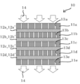
図1に、本発明の実施形態1に係る磁石フィルタ10の各構成部材の模式図を示す。図2に、本発明の実施形態1に係る磁石フィルタ10の断面図を示す。
磁石フィルタ10は、少なくとも一対の可撓性の磁石層(11a及び11b、11b及び11c、11c及び11d、11d及び11e)と、一対の磁石層の間に設けられた不織布層12a、12a’、12b、12b’、12c、12c’、12d、12d’とを備えている。
(磁石フィルタ10の構成)
図1に、本発明の実施形態1に係る磁石フィルタ10の各構成部材の模式図を示す。図2に、本発明の実施形態1に係る磁石フィルタ10の断面図を示す。
磁石フィルタ10は、少なくとも一対の可撓性の磁石層(11a及び11b、11b及び11c、11c及び11d、11d及び11e)と、一対の磁石層の間に設けられた不織布層12a、12a’、12b、12b’、12c、12c’、12d、12d’とを備えている。
磁石層11a、11b、11c、11d、11eは、可撓性材料で形成されており、例えば、磁性粉末をゴムやプラスチックなどのバインダー材と混ぜ合わせて成形したボンド磁石等で形成されている。磁石層11a、11b、11c、11d、11eは、異方着磁性であっても等方着磁性であってもよく、片面着磁性であっても両面着磁性であってもよいが、特に、異方着磁両面磁石で形成されているのが好ましい。異方着磁性は等方着磁性よりも吸着力が強く、両面着磁性は片面着磁性よりも大きい範囲で磁界を形成するため、異方着磁両面磁石を用いれば、不純物をより多く回収できる。磁石層11a、11b、11c、11d、11eは、所定の厚さを有する円板状に形成されている。磁石層11a、11b、11c、11d、11eの形状は、これに限定されず、例えば、三角形、四角形等の多角形の板状等に形成してもよい。磁石層11a、11b、11c、11d、11eは、厚さ方向に貫通する複数の孔13a、13b、13c、13d、13eが形成されている。磁石層11a、11b、11c、11d、11eの複数の孔13a、13b、13c、13d、13eは、それぞれ、円柱状に形成されている。ただし、複数の孔13a、13b、13c、13d、13eは、これに限定されず、例えば、三角柱や四角柱等の角柱状等に形成してもよい。複数の孔13a、13b、13c、13d、13eは、それぞれ規則的に配置されていてもよく、不規則に配置されていてもよい。また、複数の孔13a、13b、13c、13d、13eは略等間隔に配置されていてもよい。前記磁石層の厚さ方向に垂直な断面において、複数の孔13a、13b、13c、13d、13eの面積の総計が、前記磁石層の全面積の半分以下であることが好ましい。
不織布層12a、12a’、12b、12b’、12c、12c’、12d、12d’は、物理的・化学的手段(適当な熱や接着剤など)や機械的手段(高圧水流など)で繊維と繊維とを絡ませたり接着したりして形成された布状シートであり、微細孔を有している。不織布層12a、12a’、12b、12b’、12c、12c’、12d、12d’は、磁石層11a、11b、11c、11d、11eに対応する形状に形成されている。すなわち、本実施形態では、不織布層12a、12a’、12b、12b’、12c、12c’、12d、12d’は、磁石層11a、11b、11c、11d、11eに対応して円板状に形成されている。不織布層12a、12a’、12b、12b’、12c、12c’、12d、12d’の材質は特に限定されないが、例えば、綿、羊毛、パルプ、ポリプロピレン繊維、ポリエチレン繊維、ナイロン繊維、ビニロン繊維、ポリエステル繊維、ビスコースレーヨン繊維、又は、キュプラレーヨン繊維等であってもよく、これらの中の二種以上を包含してもよい。
実施形態1に係る磁石フィルタ10の最小構成単位は、一対の磁石層(例えば、11a及び11b)及びそれらの間に設けられた不織布層(例えば12a)の合計3層である。磁石フィルタ10は、この最小構成単位である3層に加えて、磁石層(例えば11b)の外側に不織布層(例えば12b)及び磁石層(例えば11c)をこの順で設けて5層構造にしてもよく、さらに磁石層(例えば11c)の外側に新たに不織布層(例えば12c)及び磁石層(例えば11d)をこの順で設けて7層構造にしてもよく、必要であればそれ以上の多層構造としてもよい。また、一対の磁石層の間に設けられた不織布層は2層であってもよい。図1に示した磁石フィルタ10は、一対の磁石層(11a及び11b、11b及び11c)間に2層の不織布層(12a及び12a’、12b及び12b’)を設けており、全体で7層構造であり、図2に示した磁石フィルタ10は、13層構造となっている。不織布層はこのように何層設けても良いが、その合計の厚さがあまりに厚いと、磁石層からの磁力が届き難く、磁性体不純物を回収し難くなる。従って、磁性体不純物を含んだ流体が不織布層を通るときに磁石層からの磁力が届き易く、不純物を良好に回収するという観点から、不織布層の合計の厚さは1つの磁石層の厚さ以下であるのが好ましい。
磁石フィルタ10を構成する磁石層11a、11b、11c、11d、11eの複数の孔13a、13b、13c、13d、13eは、それぞれ対向する磁石層の複数の孔と重なり合わない位置に形成するのが好ましい。不純物を含む流体14が磁石フィルタ10を通る際、磁石層11a、11b、11c、11d、11eの複数の孔13a、13b、13c、13d、13eがそれぞれ対向する磁石層の複数の孔と重なり合う位置にあれば、流体14が一方の磁石層を通過した後、その経路上にある他方の磁石層の孔をそのまま通過し易くなるが、複数の孔が重なり合わない位置にあれば、流体14が一方の磁石層を通過した後、その経路上に対向する他方の磁石層の孔がないため、通過できる孔に至るまで不織布層12a、12a’、12b、12b’、12c、12c’、12d、12d’内を移動する。これにより、不織布層12a、12a’、12b、12b’、12c、12c’、12d、12d’に流体14が留まる時間が長くなり、より良好に不純物を回収することができる。
(磁石フィルタ10を用いた磁性体不純物の回収方法)
次に、本発明の実施形態1に係る磁石フィルタ10を用いた磁性体不純物の回収方法について説明する。まず、磁石フィルタ10をハウジング(不図示)内に設置し、例えば圧力調整器(不図示)を用いてハウジング内に所定の圧力をかけた状態で、不純物である金属粉等の磁性体を含んだ流体14を供給する。供給された流体14は、ハウジング内において、図2に示すように、磁石フィルタ10の最外層である磁石層11a側から磁石フィルタ10内へ浸入する。流体14は、最外層である磁石層11aの複数の孔13aを通過し、隣接する不織布層12a、12a’に染み込む。ここで、磁石フィルタ10を構成する磁石層の複数の孔が、それぞれ対向する磁石層の複数の孔と重なり合わない位置に形成されているため、不織布層12a、12a’に染み込んだ流体14は、対向する磁石層11b内の通過できる孔13bに至るまで、不織布層12a、12a’内を移動する。このように、流体14が一対の磁石層11a、11b間を一気に通過するのではなく、不織布層12a、12a’内を移動することにより不織布層12a、12a’内で保持されて留まる時間が生じるため、不織布層12a、12a’の微細孔や磁石層11a、11bの磁界によって不織布層12a、12a’内でより多くの不純物磁性体が吸着される。また、不純物は、主に磁石層11a、11bの孔付近で生じる磁界によって吸着されるため、磁石層11a、11bに複数の孔13a、13bが形成されていることで、より多くの不純物を効率良く吸着することができる。
次に、本発明の実施形態1に係る磁石フィルタ10を用いた磁性体不純物の回収方法について説明する。まず、磁石フィルタ10をハウジング(不図示)内に設置し、例えば圧力調整器(不図示)を用いてハウジング内に所定の圧力をかけた状態で、不純物である金属粉等の磁性体を含んだ流体14を供給する。供給された流体14は、ハウジング内において、図2に示すように、磁石フィルタ10の最外層である磁石層11a側から磁石フィルタ10内へ浸入する。流体14は、最外層である磁石層11aの複数の孔13aを通過し、隣接する不織布層12a、12a’に染み込む。ここで、磁石フィルタ10を構成する磁石層の複数の孔が、それぞれ対向する磁石層の複数の孔と重なり合わない位置に形成されているため、不織布層12a、12a’に染み込んだ流体14は、対向する磁石層11b内の通過できる孔13bに至るまで、不織布層12a、12a’内を移動する。このように、流体14が一対の磁石層11a、11b間を一気に通過するのではなく、不織布層12a、12a’内を移動することにより不織布層12a、12a’内で保持されて留まる時間が生じるため、不織布層12a、12a’の微細孔や磁石層11a、11bの磁界によって不織布層12a、12a’内でより多くの不純物磁性体が吸着される。また、不純物は、主に磁石層11a、11bの孔付近で生じる磁界によって吸着されるため、磁石層11a、11bに複数の孔13a、13bが形成されていることで、より多くの不純物を効率良く吸着することができる。
続いて、不織布層12a、12a’内を移動していた流体14は、対向する磁石層11bの孔13bに至り、その孔13bを通過する。該孔13bを通過した流体14は、磁石層11bの外側に設けられている不織布層12b、12b’内へ染み込み、対向する磁石層11cの孔13cに至るまで不織布層12b、12b’内を移動し、その間に不織布層12b、12b’の微細孔や磁石層11b、11cの磁界によって吸着される。このようにして流体14が次々と磁石層及び不織布層を通過し、その都度、不純物が磁石層の磁界によって吸着され、最終的に最外層である磁石層の孔から流出する。これによって、流体14中の磁性体不純物が効率良く回収される。
(実施形態2)
(磁石フィルタ20の構成)
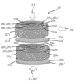
図3に、本発明の実施形態2に係る磁石フィルタ20の各構成部材の模式図を示す。
磁石フィルタ20は、少なくとも一対の可撓性の磁石層(25a及び25b、25b及び25c、25c及び25d、28a及び28b、28b及び28c、28c及び28d)と、一対の磁石層の間に設けられた不織布層26a、26a’、26b、26b’、26c、26c’、29a、29a’、29b、29b’、29c、29c’とを備えている。
(磁石フィルタ20の構成)
図3に、本発明の実施形態2に係る磁石フィルタ20の各構成部材の模式図を示す。
磁石フィルタ20は、少なくとも一対の可撓性の磁石層(25a及び25b、25b及び25c、25c及び25d、28a及び28b、28b及び28c、28c及び28d)と、一対の磁石層の間に設けられた不織布層26a、26a’、26b、26b’、26c、26c’、29a、29a’、29b、29b’、29c、29c’とを備えている。
磁石層25a、25b、25c、25d、28a、28b、28c、28dは、可撓性材料で形成されており、例えば、磁性粉末をゴムやプラスチックなどのバインダー材と混ぜ合わせて成形したボンド磁石等で形成されている。磁石層25a、25b、25c、25d、28a、28b、28c、28dは、異方着磁性であっても等方着磁性であってもよく、片面着磁性であっても両面着磁性であってもよいが、特に、異方着磁両面磁石で形成されているのが好ましい。磁石層25a、25b、25c、25d、28a、28b、28c、28dは、それぞれ所定の厚さを有する円筒状に形成されて、互いに一方の外周側又は内周側に設けられている。磁石層25a、25b、25c、25d、28a、28b、28c、28dは、厚さ方向に貫通する複数の孔27a、30aが形成されている。磁石層25a、25b、25c、25d、28a、28b、28c、28dの複数の孔27a、30aは、それぞれ、円柱状(すなわち、断面円形)に形成されている。複数の孔27a、30aは、これに限定されず、例えば、三角柱や四角柱等の角柱状等に形成してもよい。複数の孔27a、30aは、それぞれ規則的に配置されていてもよく、不規則に配置されていてもよい。また、複数の孔27a、30aは略等間隔に配置されていてもよい。前記磁石層の厚さ方向に垂直な断面において、複数の孔27a、30aの面積の総計が、前記磁石層の面積の半分以下であることが好ましい。
不織布層26a、26a’、26b、26b’、26c、26c’、29a、29a’、29b、29b’、29c、29c’は、円筒状に形成されて、一対の磁石層の間に設けられている。不織布層26a、26a’、26b、26b’、26c、26c’、29a、29a’、29b、29b’、29c、29c’の材質は特に限定されないが、例えば、綿、羊毛、パルプ、ポリプロピレン繊維、ポリエチレン繊維、ナイロン繊維、ビニロン繊維、ポリエステル繊維、ビスコースレーヨン繊維、又は、キュプラレーヨン繊維等であってもよく、これらの中の二種以上を包含してもよい。
実施形態2に係る磁石フィルタ20の最小構成単位は、一対の円筒状の磁石層(例えば25c及び25d)及びそれらの間に設けられた円筒状の不織布層(例えば26c)の合計3層で構成される単位フィルタである。単位フィルタは、この最小構成単位である3層に加えて、磁石層(例えば25c)の外側に不織布層(例えば26b)及び磁石層(例えば25b)をこの順で設けて5層構造にしてもよく、さらに磁石層(例えば25b)の外側に新たに不織布層(例えば26a)及び磁石層(例えば25a)をこの順で設けて7層構造にしてもよく、必要であればそれ以上の多層構造としてもよい。また、実施形態2に係る磁石フィルタ20は、単位フィルタ21a、21bが、不織布層22a、22a’を介して、円筒状の磁石層の厚さ方向と垂直な方向に重ねて設けられている。また、一対の磁石層の間に設けられた不織布層は2層であってもよい。図3に示した磁石フィルタ20は、一対の磁石層(25a及び25b、25b及び25c、25c及び25d、28a及び28b、28b及び28c、28c及び28d)間に、それぞれ2層の不織布層(26a及び26a’、26b及び26b’、26c及び26c’、29a及び29a’、29b及び29b’、29c及び29c’)を設けており、10層構造の単位フィルタ21a、21bを有し、さらに、この単位フィルタ21a、21bと2層の不織布層22a及び22a’、22b及び22b’とがこの順で円筒状の磁石層の厚さ方向と垂直な方向に合計で6層(2つの単位フィルタ21a及び21b、及び、4つの不織布層22a及び22a’、22b及び22b’)重ねて設けられている。不織布層はこのように何層設けても良いが、その合計の厚さがあまりに厚いと、磁石層からの磁力が届き難く、磁性体不純物を回収し難くなる。従って、磁性体不純物を含んだ流体が不織布層を通るときに磁石層からの磁力が届き易く、不純物を良好に回収するという観点から、不織布層の合計の厚さは1つの磁石層の厚さ以下であるのが好ましい。
磁石フィルタ20の単位フィルタ21a及び21bを構成する磁石層の複数の孔27a、30aは、それぞれ対向する磁石層の複数の孔27a、30aと重なり合わない位置に形成するのが好ましい。流量としては少ないが、不純物を含む流体24が磁石フィルタ20を通る場合、複数の孔27a、30aが対向する磁石層の複数の孔27a、30aと重なり合う位置にあれば、流体24が一方の磁石層を通過した後、その経路上にある他方の磁石層の孔27a、30aをそのまま通過し易くなるが、複数の孔27a、30aが重なり合わない位置にあれば、流体24が一方の磁石層を通過した後、その経路上に対向する他方の磁石層の孔27a、30aがないため、通過できる孔27a、30aに至るまで不織布層26a、26a’、26b、26b’、26c、26c’、29a、29a’、29b、29b’、29c、29c’内を移動する。これにより、不織布層26a、26a’、26b、26b’、26c、26c’、29a、29a’、29b、29b’、29c、29c’に流体が留まる時間が長くなり、より良好に不純物を回収することができる。
(磁石フィルタ20を用いた磁性体不純物の回収方法)
次に、本発明の実施形態2に係る磁石フィルタ20を用いた磁性体不純物の回収方法について説明する。まず、磁石フィルタ20をハウジング(不図示)内に設置し、例えば圧力調整器(不図示)を用いてハウジング内に所定の圧力をかけた状態で、不純物である金属粉等の磁性体を含んだ流体24を単位フィルタ21aの上面側から供給する。供給された流体24は、図3に示すように、ハウジング内において、磁石フィルタ20の一方の単位フィルタ21a側から厚さ方向へ向かって磁石フィルタ20内へ浸入する。流体24は、まず、不織布層26a、26a’、26b、26b’、26c、26c’に染み込む。また、ごくわずかであるが、磁石層25a、25b、25c、25dの複数の孔27aも通過する。不織布層26a、26a’、26b、26b’、26c、26c’に染み込んだ流体は、不織布層内を通過する間に、その微細孔や磁石層25a、25b、25c、25dの磁界によって不織布層26a、26a’、26b、26b’、26c、26c’内で不純物磁性体が吸着される。また、不純物は、主に磁石層25a、25b、25c、25dの孔27a付近で生じる磁界によって吸着されるため、磁石層25a、25b、25c、25dに複数の孔27aが形成されていることで、より多くの不純物を効率良く吸着することができる。
次に、本発明の実施形態2に係る磁石フィルタ20を用いた磁性体不純物の回収方法について説明する。まず、磁石フィルタ20をハウジング(不図示)内に設置し、例えば圧力調整器(不図示)を用いてハウジング内に所定の圧力をかけた状態で、不純物である金属粉等の磁性体を含んだ流体24を単位フィルタ21aの上面側から供給する。供給された流体24は、図3に示すように、ハウジング内において、磁石フィルタ20の一方の単位フィルタ21a側から厚さ方向へ向かって磁石フィルタ20内へ浸入する。流体24は、まず、不織布層26a、26a’、26b、26b’、26c、26c’に染み込む。また、ごくわずかであるが、磁石層25a、25b、25c、25dの複数の孔27aも通過する。不織布層26a、26a’、26b、26b’、26c、26c’に染み込んだ流体は、不織布層内を通過する間に、その微細孔や磁石層25a、25b、25c、25dの磁界によって不織布層26a、26a’、26b、26b’、26c、26c’内で不純物磁性体が吸着される。また、不純物は、主に磁石層25a、25b、25c、25dの孔27a付近で生じる磁界によって吸着されるため、磁石層25a、25b、25c、25dに複数の孔27aが形成されていることで、より多くの不純物を効率良く吸着することができる。
このようにして単位フィルタ21a内を移動していた流体24は、単位フィルタ21aに隣接して設けられた不織布層22a、22a’へ染み込む。ここでも、不織布層22a、22a’の微細孔で不純物が回収される。続いて、流体24は、不織布層22a、22a’から対向する単位フィルタ21bへ浸入する。ここでも、流体24は、まず、不織布層29a、29a’、29b、29b’、29c、29c’に染み込み、ごくわずかであるが、磁石層28a、28b、28c、28dの複数の孔30aも通過する。不織布層29a、29a’、29b、29b’、29c、29c’に染み込んだ流体は、不織布層内を通過する間に、その微細孔や磁石層28a、28b、28c、28dの磁界によって不織布層29a、29a’、29b、29b’、29c、29c’内で不純物磁性体が吸着される。また、不純物は、主に磁石層28a、28b、28c、28dの孔30a付近で生じる磁界によって吸着されるため、磁石層28a、28b、28c、28dに複数の孔30aが形成されていることで、より多くの不純物を効率良く吸着することができる。このようにして単位フィルタ21b内を移動していた流体24は、単位フィルタ21bに隣接して設けられた不織布層22b、22b’へ染み込み、不織布層22b、22b’の微細孔で不純物が回収され、最終的に不織布層22b、22b’から外部へ流出する。これによって、流体中の磁性体不純物が効率良く回収される。
なお、上述の回収方法では、磁石フィルタ20に対して単位フィルタ21aの上面側から流体24を供給したが、これに限らず、単位フィルタ21aの側面側から供給してもよい。この場合、供給された流体24’は、単位フィルタ21aの最外層である磁石層25a側から磁石フィルタ20内へ浸入する。流体24’は、最外層である磁石層25aの複数の孔27aを通過し、隣接する不織布層26a、26a’に染み込んだ後は、さらに隣接する磁石層25b及び不織布層26b、26b’、及び、下方の不織布層22a、22a’へと浸入していく。
以下、本発明の実施例を示すが、これらは本発明をより良く理解するために提供するものであり、本発明が限定されることを意図するものではない。
本発明に係る磁石フィルタを用いて、酸化鉄粉末を分散されたポリビニルアルコール水溶液(PVA水溶液)の濾過を行い、酸化鉄粉末の除去率を測定した。試験条件及び試験結果を以下に示す。
(試験サンプル)
磁石フィルタとして、以下の磁石層(1)及び磁石層(2)をこの順で交互に設け、それらの間に不織布層を2枚重ねて設けた。磁石層(1)及び磁石層(2)の合計を15層とした。また、互いに対向する磁石層(1)及び磁石層(2)の複数の孔は、互いに重ならない位置に設けた。すなわち、本実施例で用いた磁石フィルタは、上述の実施形態1で示したタイプのものである。
磁石層(1)としてゴム磁石(小野ゴム工業社製EPDM)を用いた。磁石層(1)は、円板状のEPDM異方着磁両面磁石(32mm径、厚さ1mm、孔は1.5mm径、75孔)で形成されている。
磁石層(2)としてゴム磁石(小野ゴム工業社製EPDM)を用いた。磁石層(2)は、円板状のEPDM異方着磁両面磁石(32mm径、厚さ1mm、孔は1.5mm径、61孔)で形成されている。 不織布層として、厚さ0.5mm以下の日本バイリーン社製の32mm径の円板状の不織布を用いた。
上述の磁石フィルタを、SUS304ステンレス鋼で形成されたハウジング内に設置した。
磁石フィルタとして、以下の磁石層(1)及び磁石層(2)をこの順で交互に設け、それらの間に不織布層を2枚重ねて設けた。磁石層(1)及び磁石層(2)の合計を15層とした。また、互いに対向する磁石層(1)及び磁石層(2)の複数の孔は、互いに重ならない位置に設けた。すなわち、本実施例で用いた磁石フィルタは、上述の実施形態1で示したタイプのものである。
磁石層(1)としてゴム磁石(小野ゴム工業社製EPDM)を用いた。磁石層(1)は、円板状のEPDM異方着磁両面磁石(32mm径、厚さ1mm、孔は1.5mm径、75孔)で形成されている。
磁石層(2)としてゴム磁石(小野ゴム工業社製EPDM)を用いた。磁石層(2)は、円板状のEPDM異方着磁両面磁石(32mm径、厚さ1mm、孔は1.5mm径、61孔)で形成されている。 不織布層として、厚さ0.5mm以下の日本バイリーン社製の32mm径の円板状の不織布を用いた。
上述の磁石フィルタを、SUS304ステンレス鋼で形成されたハウジング内に設置した。
(試験液)
Fe3O4(関東化学社製:鹿1級)の粉末をPVA水溶液に分散させて撹拌し、粘度を30mPa・sに調整して試験液とした。試験液はFe3O4濃度によって3種類準備し、それぞれ試験液1(Fe3O4濃度:3.33g/l)、試験液2(Fe3O4濃度:1.67g/l)、試験液3(Fe3O4濃度:0.33g/l)とした。
Fe3O4(関東化学社製:鹿1級)の粉末をPVA水溶液に分散させて撹拌し、粘度を30mPa・sに調整して試験液とした。試験液はFe3O4濃度によって3種類準備し、それぞれ試験液1(Fe3O4濃度:3.33g/l)、試験液2(Fe3O4濃度:1.67g/l)、試験液3(Fe3O4濃度:0.33g/l)とした。
(試験手順)
試験液を、ハウジング内の磁石フィルタの最上層である磁石層(1)側から供給し、圧力10kPaにて定圧濾過を行った。
続いて、磁石フィルタの最下層である磁石層(2)から流出する濾過液を、200mlずつ採取した。
次に、各濾過液50mlを、あらかじめ重量を測定した酸化鉄粉捕捉用濾紙(ミリポア社製AN25〔孔径2.5μm、直径25mm〕)にて濾過し、続いて、酸化鉄粉捕捉用濾紙及び超純水500mlによる濾過を行い、濾紙に付着したPVA残渣を十分に洗い流した。
次に、濾紙を風乾した後、秤量し、酸化鉄粉の捕捉量を測定した。また、酸化鉄粉の捕捉量と試験液濾過量とにより、磁石フィルタ濾過液中の酸化鉄濃度を算出した。
試験液を、ハウジング内の磁石フィルタの最上層である磁石層(1)側から供給し、圧力10kPaにて定圧濾過を行った。
続いて、磁石フィルタの最下層である磁石層(2)から流出する濾過液を、200mlずつ採取した。
次に、各濾過液50mlを、あらかじめ重量を測定した酸化鉄粉捕捉用濾紙(ミリポア社製AN25〔孔径2.5μm、直径25mm〕)にて濾過し、続いて、酸化鉄粉捕捉用濾紙及び超純水500mlによる濾過を行い、濾紙に付着したPVA残渣を十分に洗い流した。
次に、濾紙を風乾した後、秤量し、酸化鉄粉の捕捉量を測定した。また、酸化鉄粉の捕捉量と試験液濾過量とにより、磁石フィルタ濾過液中の酸化鉄濃度を算出した。
(試験結果)
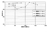
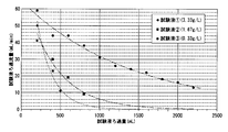
図4に、上記実施例に係る酸化鉄粉の除去率(%)と試験液濾過量(ml)との関係を表すグラフを示す。図5に、上記実施例に係る酸化鉄粉の除去率(%)と酸化鉄粉捕捉量(mg)との関係を表すグラフを示す。図6に、上記実施例に係る試験液濾過流量(ml/min)と試験液濾過量(ml)との関係を表すグラフを示す。図7に、上記実施例に係る試験液濾過流量(ml/min)と酸化鉄粉捕捉量(mg)との関係を表すグラフを示す。
Fe3O4濃度0.33~3.33g/lの3種類の試験液を濾過したとき、いずれの試験液においても磁石フィルタが90%以上のFe3O4粉の除去率を示している(図4及び5)。また、磁石層の重ね枚数を増やす、又は、磁石層の直径を大きくする等によって更なる除去率の向上を図ることが可能であると考えられる。
また、試験液の濾過量が増すと磁石フィルタの濾過流量が徐々に低下する(図6及び7)が、Fe3O4粉の除去率には大きな変動は生じていないことがわかる(図4及び5)。この結果は、定圧濾過を行うことにより、磁石フィルタが目詰まりを生じるまでFe3O4粉の除去能力が低下せず、安定的に機能することを示唆している。
図4に、上記実施例に係る酸化鉄粉の除去率(%)と試験液濾過量(ml)との関係を表すグラフを示す。図5に、上記実施例に係る酸化鉄粉の除去率(%)と酸化鉄粉捕捉量(mg)との関係を表すグラフを示す。図6に、上記実施例に係る試験液濾過流量(ml/min)と試験液濾過量(ml)との関係を表すグラフを示す。図7に、上記実施例に係る試験液濾過流量(ml/min)と酸化鉄粉捕捉量(mg)との関係を表すグラフを示す。
Fe3O4濃度0.33~3.33g/lの3種類の試験液を濾過したとき、いずれの試験液においても磁石フィルタが90%以上のFe3O4粉の除去率を示している(図4及び5)。また、磁石層の重ね枚数を増やす、又は、磁石層の直径を大きくする等によって更なる除去率の向上を図ることが可能であると考えられる。
また、試験液の濾過量が増すと磁石フィルタの濾過流量が徐々に低下する(図6及び7)が、Fe3O4粉の除去率には大きな変動は生じていないことがわかる(図4及び5)。この結果は、定圧濾過を行うことにより、磁石フィルタが目詰まりを生じるまでFe3O4粉の除去能力が低下せず、安定的に機能することを示唆している。
10、20 磁石フィルタ
11a、11b、11c、11d、11e、25a、25b、25c、25d、28a、28b、28c、28d 磁石層
13a、13b、13c、13d、13e、27a、30a 孔
12a、12a’、12b、12b’、12c、12c’、12d、12d’、26a、26a’、26b、26b’、26c、26c’、29a、29a’、29b、29b’、29c、29c’ 不織布層
21a、21b 単位フィルタ
11a、11b、11c、11d、11e、25a、25b、25c、25d、28a、28b、28c、28d 磁石層
13a、13b、13c、13d、13e、27a、30a 孔
12a、12a’、12b、12b’、12c、12c’、12d、12d’、26a、26a’、26b、26b’、26c、26c’、29a、29a’、29b、29b’、29c、29c’ 不織布層
21a、21b 単位フィルタ
Claims (10)
- それぞれ厚さ方向に貫通する複数の孔が形成された、少なくとも一対の可撓性の磁石層と、
前記一対の磁石層の間に設けられた不織布層と、
を備えた磁石フィルタ。 - 前記孔の、前記磁石層の厚さ方向に垂直な断面形状が円形である、請求項1に記載の磁石フィルタ。
- 前記孔が略等間隔に配置されている、請求項1又は2に記載の磁石フィルタ。
- 前記磁石層の複数の孔は、それぞれ対向する前記磁石層の複数の孔と重なり合わない位置に形成されている請求項1ないし3のいずれか一項に記載の磁石フィルタ。
- 前記磁石層の厚さ方向に垂直な断面において、前記孔の面積の総計が、前記磁石層の全面積の半分以下である請求項1ないし4のいずれか一項に記載の磁石フィルタ。
- 前記磁石層が、異方着磁両面磁石で形成されている請求項1~5のいずれか一項に記載の磁石フィルタ。
- 前記少なくとも一対の磁石層は、それぞれ円筒状に形成されて、互いに一方の外周側又は内周側に設けられ、
前記不織布層は、円筒状に形成されて、前記一対の磁石層の間に設けられている請求項1~6のいずれか一項に記載の磁石フィルタ。 - 前記少なくとも一対の円筒状の磁石層と、前記一対の磁石層の間に設けられた円筒状の不織布層とが単位フィルタを構成し、
前記単位フィルタが、不織布層を介して、前記円筒状の磁石層の厚さ方向と垂直な方向に重ねて設けられている請求項7に記載の磁石フィルタ。 - 前記一対の磁石層の間に設けられた不織布層の厚さが該磁石層の厚さ以下である請求項1~8のいずれか一項に記載の磁石フィルタ。
- 磁性体不純物を含む流体から、請求項1~9のいずれか一項に記載の磁石フィルタを用いて前記磁性体不純物を回収する方法。
Applications Claiming Priority (2)
| Application Number | Priority Date | Filing Date | Title |
|---|---|---|---|
| JP2010131265 | 2010-06-08 | ||
| JP2010-131265 | 2010-06-08 |
Publications (1)
| Publication Number | Publication Date |
|---|---|
| WO2011155431A1 true WO2011155431A1 (ja) | 2011-12-15 |
Family
ID=45098038
Family Applications (1)
| Application Number | Title | Priority Date | Filing Date |
|---|---|---|---|
| PCT/JP2011/062913 Ceased WO2011155431A1 (ja) | 2010-06-08 | 2011-06-06 | 磁石フィルタ及びそれを用いた不純物回収方法 |
Country Status (1)
| Country | Link |
|---|---|
| WO (1) | WO2011155431A1 (ja) |
Citations (4)
| Publication number | Priority date | Publication date | Assignee | Title |
|---|---|---|---|---|
| JPS5250067A (en) * | 1975-10-16 | 1977-04-21 | Caterpillar Tractor Co | Magnetic filter element |
| JPH09253631A (ja) * | 1996-03-27 | 1997-09-30 | Kanegafuchi Chem Ind Co Ltd | 水処理装置 |
| JPH10118634A (ja) * | 1996-10-16 | 1998-05-12 | Minamimachi Sangyo Kk | 濾過装置 |
| JP2000317443A (ja) * | 1999-05-12 | 2000-11-21 | Dedo Suisen Kk | 浄水器の濾材仕切り構造 |
-
2011
- 2011-06-06 WO PCT/JP2011/062913 patent/WO2011155431A1/ja not_active Ceased
Patent Citations (4)
| Publication number | Priority date | Publication date | Assignee | Title |
|---|---|---|---|---|
| JPS5250067A (en) * | 1975-10-16 | 1977-04-21 | Caterpillar Tractor Co | Magnetic filter element |
| JPH09253631A (ja) * | 1996-03-27 | 1997-09-30 | Kanegafuchi Chem Ind Co Ltd | 水処理装置 |
| JPH10118634A (ja) * | 1996-10-16 | 1998-05-12 | Minamimachi Sangyo Kk | 濾過装置 |
| JP2000317443A (ja) * | 1999-05-12 | 2000-11-21 | Dedo Suisen Kk | 浄水器の濾材仕切り構造 |
Similar Documents
| Publication | Publication Date | Title |
|---|---|---|
| US20200122069A1 (en) | Elastomeric depth filter | |
| CN105644085B (zh) | 多层复合纳米纤维膜及其应用 | |
| EP4382187A2 (en) | Biocide-loaded electrospun nanofibers supported by adhesive-free thin fabric for pathogen removal filtration | |
| KR102138010B1 (ko) | 수처리 장치의 복합 필터 | |
| JP2009148748A (ja) | フィルターおよびフィルターユニット | |
| US7938276B2 (en) | Filtration architecture for optimized performance | |
| KR20160031978A (ko) | 필터 | |
| CN107635637B (zh) | 吸附式液体过滤器 | |
| JP2007296484A (ja) | 水処理用フィルター | |
| CN108778460A (zh) | 用于燃料过滤器的滤芯的过滤材料、滤芯和燃料过滤器 | |
| JP2009112887A (ja) | 濾過材およびその製造方法、並びにカートリッジフィルター | |
| KR101377477B1 (ko) | 절곡형 심층필터 | |
| CN210915612U (zh) | 复合滤芯及净水系统 | |
| WO2011155431A1 (ja) | 磁石フィルタ及びそれを用いた不純物回収方法 | |
| JP6150279B2 (ja) | 放射性物質のモニタリングに用いられる、液体試料中の放射性物質収集装置 | |
| KR101385947B1 (ko) | Cmp 공정의 슬러리 여과용 심층필터 | |
| CN210915611U (zh) | 复合滤芯及净水系统 | |
| JPH09220417A (ja) | 磁気フィルターおよび磁気マスク | |
| WO2014025689A1 (en) | Filter for a water purifier, and a water purifier including the same | |
| JP6560945B2 (ja) | エアフィルター | |
| JP3195923U (ja) | フィルター | |
| CN204338024U (zh) | 用于对流体进行过滤的正渗透膜组 | |
| JP2011251249A (ja) | 液体用フィルター材 | |
| JP3677367B2 (ja) | 筒状フィルタ | |
| JP2004305857A (ja) | フィルタエレメント |
Legal Events
| Date | Code | Title | Description |
|---|---|---|---|
| 121 | Ep: the epo has been informed by wipo that ep was designated in this application |
Ref document number: 11792388 Country of ref document: EP Kind code of ref document: A1 |
|
| NENP | Non-entry into the national phase |
Ref country code: DE |
|
| 122 | Ep: pct application non-entry in european phase |
Ref document number: 11792388 Country of ref document: EP Kind code of ref document: A1 |