WO2011155361A1 - 無線通信システム、基地局装置、移動局装置、無線通信方法および集積回路 - Google Patents
無線通信システム、基地局装置、移動局装置、無線通信方法および集積回路 Download PDFInfo
- Publication number
- WO2011155361A1 WO2011155361A1 PCT/JP2011/062380 JP2011062380W WO2011155361A1 WO 2011155361 A1 WO2011155361 A1 WO 2011155361A1 JP 2011062380 W JP2011062380 W JP 2011062380W WO 2011155361 A1 WO2011155361 A1 WO 2011155361A1
- Authority
- WO
- WIPO (PCT)
- Prior art keywords
- reference signal
- station apparatus
- base station
- mobile station
- sounding reference
- Prior art date
- Legal status (The legal status is an assumption and is not a legal conclusion. Google has not performed a legal analysis and makes no representation as to the accuracy of the status listed.)
- Ceased
Links
Images


Classifications
-
- H—ELECTRICITY
- H04—ELECTRIC COMMUNICATION TECHNIQUE
- H04L—TRANSMISSION OF DIGITAL INFORMATION, e.g. TELEGRAPHIC COMMUNICATION
- H04L5/00—Arrangements affording multiple use of the transmission path
- H04L5/003—Arrangements for allocating sub-channels of the transmission path
- H04L5/0048—Allocation of pilot signals, i.e. of signals known to the receiver
-
- H—ELECTRICITY
- H04—ELECTRIC COMMUNICATION TECHNIQUE
- H04B—TRANSMISSION
- H04B7/00—Radio transmission systems, i.e. using radiation field
- H04B7/14—Relay systems
- H04B7/15—Active relay systems
- H04B7/204—Multiple access
- H04B7/208—Frequency-division multiple access [FDMA]
-
- H—ELECTRICITY
- H04—ELECTRIC COMMUNICATION TECHNIQUE
- H04L—TRANSMISSION OF DIGITAL INFORMATION, e.g. TELEGRAPHIC COMMUNICATION
- H04L25/00—Baseband systems
- H04L25/02—Details ; arrangements for supplying electrical power along data transmission lines
- H04L25/0202—Channel estimation
- H04L25/0224—Channel estimation using sounding signals
-
- H—ELECTRICITY
- H04—ELECTRIC COMMUNICATION TECHNIQUE
- H04W—WIRELESS COMMUNICATION NETWORKS
- H04W72/00—Local resource management
- H04W72/20—Control channels or signalling for resource management
- H04W72/23—Control channels or signalling for resource management in the downlink direction of a wireless link, i.e. towards a terminal
-
- H—ELECTRICITY
- H04—ELECTRIC COMMUNICATION TECHNIQUE
- H04L—TRANSMISSION OF DIGITAL INFORMATION, e.g. TELEGRAPHIC COMMUNICATION
- H04L1/00—Arrangements for detecting or preventing errors in the information received
- H04L1/12—Arrangements for detecting or preventing errors in the information received by using return channel
- H04L1/16—Arrangements for detecting or preventing errors in the information received by using return channel in which the return channel carries supervisory signals, e.g. repetition request signals
- H04L1/1607—Details of the supervisory signal
- H04L1/1671—Details of the supervisory signal the supervisory signal being transmitted together with control information
-
- H—ELECTRICITY
- H04—ELECTRIC COMMUNICATION TECHNIQUE
- H04L—TRANSMISSION OF DIGITAL INFORMATION, e.g. TELEGRAPHIC COMMUNICATION
- H04L25/00—Baseband systems
- H04L25/02—Details ; arrangements for supplying electrical power along data transmission lines
- H04L25/0202—Channel estimation
- H04L25/0204—Channel estimation of multiple channels
-
- H—ELECTRICITY
- H04—ELECTRIC COMMUNICATION TECHNIQUE
- H04L—TRANSMISSION OF DIGITAL INFORMATION, e.g. TELEGRAPHIC COMMUNICATION
- H04L5/00—Arrangements affording multiple use of the transmission path
- H04L5/0001—Arrangements for dividing the transmission path
- H04L5/0003—Two-dimensional division
- H04L5/0005—Time-frequency
- H04L5/0007—Time-frequency the frequencies being orthogonal, e.g. OFDM(A) or DMT
- H04L5/001—Time-frequency the frequencies being orthogonal, e.g. OFDM(A) or DMT the frequencies being arranged in component carriers
-
- H—ELECTRICITY
- H04—ELECTRIC COMMUNICATION TECHNIQUE
- H04L—TRANSMISSION OF DIGITAL INFORMATION, e.g. TELEGRAPHIC COMMUNICATION
- H04L5/00—Arrangements affording multiple use of the transmission path
- H04L5/003—Arrangements for allocating sub-channels of the transmission path
- H04L5/0044—Allocation of payload; Allocation of data channels, e.g. PDSCH or PUSCH
-
- H—ELECTRICITY
- H04—ELECTRIC COMMUNICATION TECHNIQUE
- H04L—TRANSMISSION OF DIGITAL INFORMATION, e.g. TELEGRAPHIC COMMUNICATION
- H04L5/00—Arrangements affording multiple use of the transmission path
- H04L5/003—Arrangements for allocating sub-channels of the transmission path
- H04L5/0053—Allocation of signalling, i.e. of overhead other than pilot signals
Definitions
- the present invention relates to a radio communication system composed of a mobile station apparatus and a base station apparatus, and more particularly to a transmission control method for a reference signal for channel measurement of the mobile station apparatus.
- LTE Long Term Evolution
- EUTRA Advanced Universal Terrestrial Radio Access
- LTE-A Long Term Evolution-Advanced
- A- EUTRA Advanced Evolved Universal Terrestrial Radio Access
- OFDMA Orthogonal Frequency Division Multiple Access
- SC-FDMA Single Carrier-Frequency Division Multiple Access
- the OFDMA method is used in the downlink, and in the uplink, in addition to the SC-FDMA method, Clustered-SC-FDMA (Clustered-Single Carrier-Frequency Division Multiple Access -OFDM with Spectrum Division Control (also called DFT-precoded OFDM) is being considered.
- the SC-FDMA system and the Clustered-SC-FDMA system proposed as uplink communication systems are based on the characteristics of the single carrier communication system (depending on the single carrier characteristics), and data (information ) Is transmitted at a low PAPR (Peak to Average Power Ratio: peak power to average power ratio, transmission power).
- a frequency band used in a general wireless communication system is continuous, a plurality of continuous and / or discontinuous frequency bands (hereinafter referred to as “component carrier (CC)”)
- component carrier CC
- CC composite frequency band
- UE User Equipment
- asymmetric frequency band aggregation Asymmetric carrier aggregation
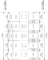
- FIG. 6 is a diagram for explaining a radio communication system in which frequency bands are aggregated in the conventional technology. It is symmetric that the frequency band used for downlink (DL: Down Link) communication and the frequency band used for uplink (UL: ⁇ ⁇ Up Link) communication as shown in FIG. It is also called frequency band aggregation (Symmetric carrier aggregation). As shown in FIG. 6, the base station apparatus and the mobile station apparatus can use a wide band composed of a plurality of component carriers by using a plurality of component carriers that are continuous and / or discontinuous frequency bands. Communication can be performed in the frequency band.
- DL Down Link
- UL ⁇ ⁇ Up Link
- Symmetric carrier aggregation Symmetric carrier aggregation
- the frequency band (DL system band (width) may be used) for downlink communication having a bandwidth of 100 MHz is five downlink component carriers having a bandwidth of 20 MHz ( DCC1: “Downlink” Component “Carrier1, DCC2, DCC3, DCC4, DCC5)”.
- the frequency band (UL system band (width) may be used) for uplink communication having a bandwidth of 100 MHz is five uplink component carriers (UCC1: Uplink Component Carrier1, UCC2, UCC3, UCC4, UCC5).
- downlink channels such as a physical downlink control channel (PDCCH: Physical Downlink Control Channel) and a physical downlink shared channel (PDSCH: Physical Downlink Shared Channel) are arranged in each downlink component carrier.
- PDCCH Physical Downlink Control Channel
- PDSCH Physical Downlink Shared Channel
- the base station apparatus allocates (schedules) downlink control information (DCI: Downlink Control Information) for transmitting a downlink transport block transmitted using the PDSCH to the mobile station device using the PDCCH. .
- DCI Downlink Control Information
- the base station apparatus transmits the downlink transport block to the mobile station apparatus using PDSCH.
- the base station apparatus can transmit up to five downlink transport blocks (or PDSCH) to the mobile station apparatus in the same subframe.
- uplink channels such as a physical uplink control channel (PUCCH: “Physical” Uplink “Control” Channel) and a physical uplink shared channel (PUSCH): “Physical” Uplink “Shared” Channel) are arranged in each uplink component carrier.
- PUCCH Physical Uplink control channel
- PUSCH physical uplink shared channel
- the mobile station apparatus uses PUCCH and / or PUSCH to indicate channel state information (CSI: Channel Statement information) indicating downlink channel state and ACK / NACK (acknowledgment: Positive) in HARQ for the downlink transport block.
- CSI Channel Statement information
- ACK / NACK acknowledgenowledgment: Positive
- Information indicating Acknowledgment / Negative Acknowledgment (NegativeUCAcknowledgement) and uplink control information (UCI: Uplink Control Information) such as scheduling request (SR: Scheduling Request) are transmitted to the base station apparatus.
- SR Scheduling Request
- the mobile station apparatus can transmit up to five uplink transport blocks (or PUSCH) to the base station apparatus in the same subframe.
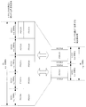
- FIG. 7 is a diagram for explaining a wireless communication system in which asymmetric frequency bands are aggregated in the prior art.
- the base station apparatus and the mobile station apparatus have different frequency bands used for downlink communication and frequency bands used for uplink communication, and configure these frequency bands. It is possible to perform communication in a wide frequency band by using a component carrier that is a continuous and / or discontinuous frequency band.
- each downlink component carrier DCC1, DCC2, DCC3, DCC4, DCC5
- the frequency band used for uplink communication having a bandwidth of 40 MHz is configured by two uplink component carriers (UCC1, UCC2) having a bandwidth of 20 MHz. ing.
- downlink / uplink channels are allocated to downlink / uplink component carriers, respectively.
- the base station apparatus allocates (schedules) the PDSCH to the mobile station apparatus using the PDCCH, and transmits the downlink transport block to the mobile station apparatus using the PDSCH.
- the base station apparatus can transmit up to five downlink transport blocks (or PDSCH) to the mobile station apparatus in the same subframe.
- the mobile station apparatus uses PUCCH and / or PUSCH to transmit channel state information, information indicating ACK / NACK in HARQ for the downlink transport block, and uplink control information such as a scheduling request to the base station apparatus. Send to.
- the mobile station apparatus can transmit up to two uplink transport blocks (or PUSCH) to the base station apparatus in the same subframe.
- LTE-A proposes a sounding reference signal (A-SRS: “Aperiodic” Sounding “Reference” Signal) that is transmitted only when a transmission request is notified from the base station apparatus through the PDCCH.
- A-SRS sounding reference signal
- DCI Downlink Control Information
- the mobile station apparatus can It is possible to determine whether or not SRS transmission is requested, and to dynamically control A-SRS transmission.
- the base station apparatus uses the downlink control information format for the downlink (DCI format, downlink grant: Downlink ⁇ grant, downlink assignment: also called Downlink assignment) for the mobile station device, and A -Instructing transmission of SRS and transmitting A-SRS using downlink control information format for uplink (DCI format, uplink grant: UL grant, uplink assignment: also called Uplink assignment) It has been proposed to direct. Further, it has been proposed that an A-SRS transmission instruction is indicated by one bit (multi-bit) of an uplink grant or downlink assignment or a predetermined code point (Non-patent Document 2).
- the mobile station apparatus instructed to transmit A-SRS by the base station apparatus transmits A-SRS to the base station apparatus without switching the parameter used for A-SRS transmission. That is, the mobile station apparatus arranges the A-SRS in the PUSCH resource (a part of the PUSCH resource) scheduled by the base station apparatus and transmits it to the base station apparatus (in-band A-SRS transmission). For example, the mobile station apparatus transmits A-SRS to the base station apparatus with the same transmission bandwidth as the PUSCH resource scheduled by the base station apparatus.
- the mobile station apparatus transmits the A-SRS to the base station apparatus by setting the A-SRS in the resource set by the base station apparatus with the setting information different from the setting information for the PUSCH resource (outbound A-SRS transmission). .
- the mobile station apparatus transmits A-SRS to the base station apparatus with a wide transmission bandwidth set by the base station apparatus.
- the mobile station device when the mobile station device communicates with the base station device in an environment with good communication quality, even if the A-SRS is transmitted in-band, the base station device is within the range of PUSCH resources scheduled for the mobile station device.
- efficient communication cannot be performed.
- the mobile station device communicates with the base station device in an environment with poor communication quality, even if the A-SRS is transmitted out-of-band, the channel measurement accuracy by the base station device deteriorates, and efficient communication is performed. I can't do it.
- the mobile station apparatus instructed to transmit A-SRS by the base station apparatus transmits A-SRS to the base station apparatus without switching the parameter used for A-SRS transmission.
- efficient communication cannot be performed between the base station apparatus and the mobile station apparatus.
- the present invention has been made in view of the above points, and can perform efficient communication between a base station apparatus and a mobile station apparatus based on an A-SRS transmitted from the mobile station apparatus.
- An object is to provide a radio communication system, a base station apparatus, a mobile station apparatus, a radio communication method, and an integrated circuit.
- the radio communication system of the present invention is a radio communication system in which a base station apparatus and a mobile station apparatus perform radio communication, and the base station apparatus is arranged in a physical uplink shared channel resource.
- Radio resource control including transmission control information for setting whether to transmit a sounding reference signal or to transmit a second sounding reference signal arranged in a resource different from the physical uplink shared channel resource
- a signal is transmitted to the mobile station device, and the mobile station device is notified of the uplink grant including a sounding reference signal transmission instruction, and the mobile station device transmits the sounding reference signal included in the uplink grant.
- transmission of the first sounding reference signal is set by the transmission control information.
- the first sounding reference signal is transmitted to the base station apparatus, and when the transmission of the second sounding reference signal is set by the transmission control information, the second sounding reference signal is transmitted.
- a sounding reference signal is transmitted to the base station apparatus.
- the radio communication system of the present invention is a radio communication system in which a base station apparatus and a mobile station apparatus perform radio communication, and the base station apparatus is arranged in a physical uplink shared channel resource.
- An uplink grant including control information indicating whether a second sounding reference signal to be transmitted or a second sounding reference signal arranged in a resource different from the physical uplink shared channel resource is transmitted to the mobile station apparatus
- the mobile station apparatus transmits the first sounding reference signal or the second sounding reference signal to the base station apparatus based on control information included in the uplink grant.
- the radio communication system of the present invention is a radio communication system in which a base station apparatus and a mobile station apparatus perform radio communication, and the base station apparatus is arranged in a physical uplink shared channel resource.
- the transmission instruction information included in the uplink grant is set as the first value and is arranged in a resource different from the physical uplink shared channel resource.
- the transmission instruction information is set as a second value, and the transmission instruction information set to the first value or the second value is set.
- the mobile station apparatus notifies the mobile station apparatus of the uplink grant including the transmission instruction information included in the uplink grant.
- the first sounding reference signal is transmitted to the base station apparatus, and when the transmission instruction information included in the uplink grant is the second value, the second sounding reference signal is transmitted.
- a reference signal is transmitted to the base station apparatus.
- the radio communication system of the present invention is a radio communication system in which a base station apparatus and a mobile station apparatus perform radio communication, and the base station apparatus is arranged in a physical uplink shared channel resource.
- a base station apparatus and a mobile station apparatus perform radio communication
- the base station apparatus is arranged in a physical uplink shared channel resource.
- 1-bit transmission instruction information included in the uplink grant is set to a predetermined value and arranged in a resource different from the physical uplink shared channel resource.
- the first control information included in the uplink grant is set to a predetermined code point, and the transmission instruction of the sounding reference signal is transmitted. Set with the instruction information or the first control information, and the transmission instruction information set with the predetermined value or the predetermined control information.
- the mobile station apparatus notifies the mobile station apparatus of an uplink grant including the first control information set at a point, and notifies the mobile station apparatus of an uplink grant including an instruction to transmit the sounding reference signal. Transmits the first sounding reference signal to the base station apparatus when the transmission instruction information included in the uplink grant indicates a transmission instruction of the sounding reference signal, and transmits the first sounding reference signal to the uplink grant.
- the first control information included is a predetermined code point
- the second sounding reference signal is transmitted to the base station apparatus.
- a radio communication system is the radio communication system according to (1), wherein the base station apparatus transmits a transmission instruction of the sounding reference signal using 1-bit transmission instruction information or a predetermined code point. It is characterized by being set with some first control information.
- the radio communication system according to the present invention is the radio communication system according to (1), wherein the base station apparatus sets the transmission control information for each uplink component carrier.
- the radio communication system according to the present invention is the radio communication system according to (4), wherein the base station apparatus includes an uplink including the parameter of the second sounding reference signal and the first control information.
- the mobile station apparatus notifies the mobile station apparatus of the grant, and when the first control information is a predetermined code point according to the uplink grant, the mobile station apparatus sets the parameter included in the uplink grant.
- the set second sounding reference signal is transmitted to the base station apparatus.
- a base station apparatus is a base station apparatus that performs radio communication with a mobile station apparatus, and transmits a first sounding reference signal arranged in a physical uplink shared channel resource, Means for notifying the mobile station apparatus of a radio resource control signal including transmission control information for setting in the mobile station apparatus whether to transmit a second sounding reference signal arranged in a resource different from the uplink shared channel resource And at least means for notifying the mobile station apparatus of an uplink grant including a sounding reference signal transmission instruction.
- a base station apparatus is a base station apparatus that performs radio communication with a mobile station apparatus, and transmits a first sounding reference signal arranged in a physical uplink shared channel resource, It has at least means for notifying the mobile station apparatus of an uplink grant including control information indicating whether to transmit a second sounding reference signal arranged in a resource different from an uplink shared channel resource. .
- a base station apparatus is a base station apparatus that performs radio communication with a mobile station apparatus, and transmits the first sounding reference signal arranged in a physical uplink shared channel resource.
- the means for setting the transmission instruction information as a second value and the uplink grant including the transmission instruction information set to the first value or the second value as the mobile And at least means for notifying the station apparatus.
- a base station apparatus is a base station apparatus that performs radio communication with a mobile station apparatus, and transmits the first sounding reference signal arranged in a physical uplink shared channel resource.
- the second sounding reference signal is arranged in a resource different from the physical uplink shared channel resource, and means for setting the 1-bit transmission instruction information included in the uplink grant to a predetermined value.
- a means for setting the first control information included in the uplink grant to a predetermined code point, and a transmission instruction of a sounding reference signal as the transmission instruction information or the first Means for setting with control information, and transmission instruction information set to the predetermined value or set to the predetermined code point Means for notifying the mobile station apparatus of an uplink grant including the first control information, and means for notifying the mobile station apparatus of an uplink grant including an instruction to transmit the sounding reference signal. It is characterized by.
- a mobile station apparatus is a mobile station apparatus that performs radio communication with a base station apparatus, wherein the mobile station apparatus receives transmission control information notified from the base station apparatus, and is notified from the base station apparatus.
- the transmission of the first sounding reference signal is set by the transmission control information when the means for receiving the uplink grant and the transmission instruction of the sounding reference signal included in the uplink grant are received
- the second sounding reference signal is set to be transmitted by the means for transmitting the first sounding reference signal to the base station apparatus and the transmission control information
- the second sounding reference signal is And means for transmitting to the base station apparatus.
- a mobile station apparatus is a mobile station apparatus that performs radio communication with a base station apparatus, and includes means for receiving an uplink grant notified from the base station apparatus, and is included in the uplink grant And at least means for transmitting the first sounding reference signal or the second sounding reference signal to the base station apparatus based on the control information.
- a mobile station apparatus is a mobile station apparatus that performs radio communication with a base station apparatus, and includes means for receiving an uplink grant notified from the base station apparatus, and is included in the uplink grant
- the transmission instruction information is the first value
- the means for transmitting the first sounding reference signal to the base station apparatus, and the transmission instruction information included in the uplink grant is the second value
- a mobile station apparatus is a mobile station apparatus that performs radio communication with a base station apparatus, and includes means for receiving an uplink grant notified from the base station apparatus, and is included in the uplink grant
- the transmission instruction information indicates an instruction to transmit a sounding reference signal
- means for transmitting the first sounding reference signal to the base station apparatus and first control information included in the uplink grant are predetermined.
- it has at least means for transmitting a second sounding reference signal to the base station apparatus.
- a radio communication method of the present invention is a radio communication method in which a base station apparatus and a mobile station apparatus perform radio communication, and the base station apparatus is arranged in a physical uplink shared channel resource. Transmission control information for setting to the mobile station apparatus whether to transmit a second sounding reference signal to be transmitted or a second sounding reference signal arranged in a resource different from the physical uplink shared channel resource.
- a step of notifying a device a step of notifying the mobile station device including a sounding reference signal transmission instruction in an uplink grant, and the mobile station device transmitting a sounding reference signal included in the uplink grant When the first sounding reference signal is set to be transmitted by the transmission control information.
- the second sounding reference signal when the transmission of the second sounding reference signal is set by the step of transmitting the first sounding reference signal to the base station apparatus and the transmission control information, the second sounding reference signal is set. And a step of transmitting a reference signal to the base station apparatus.
- a radio communication method is a radio communication method in which a base station apparatus and a mobile station apparatus perform radio communication, and the base station apparatus is arranged in a physical uplink shared channel resource.
- An uplink grant including control information indicating whether a second sounding reference signal to be transmitted or a second sounding reference signal arranged in a resource different from the physical uplink shared channel resource is transmitted to the mobile station apparatus Notifying, and the mobile station apparatus, based on control information included in the uplink grant, transmitting the first sounding reference signal or the second sounding reference signal to the base station apparatus; It is characterized by including at least.
- a radio communication method is a radio communication method in which a base station apparatus and a mobile station apparatus perform radio communication, wherein the base station apparatus is arranged in a physical uplink shared channel resource.
- the transmission instruction information included in the uplink grant is set as a first value
- the physical uplink shared channel resource is arranged in a different resource.
- the step of transmitting the first sounding reference signal to the base station apparatus, and the transmission instruction information included in the uplink grant is the second value. If it is a value, it includes at least a step of transmitting the second sounding reference signal to the base station apparatus.
- a radio communication method of the present invention is a radio communication method in which a base station apparatus and a mobile station apparatus perform radio communication, wherein the base station apparatus is arranged in a physical uplink shared channel resource.
- a step of setting 1-bit transmission instruction information included in the uplink grant to a predetermined value and a resource different from the physical uplink shared channel resource When instructing the mobile station apparatus to transmit the second sounding reference signal arranged in the base station, a step of setting the first control information included in the uplink grant to a predetermined code point, and transmission of the sounding reference signal Setting an instruction with the transmission instruction information or the first control information, and setting the instruction to the predetermined value Notification of uplink grant including transmission instruction information or first control information set at the predetermined code point to the mobile station apparatus, and uplink grant including an instruction to transmit the sounding reference signal to the mobile station A step of notifying a device, and when the transmission instruction information included in the uplink grant indicates a transmission instruction of the sounding reference signal
- An integrated circuit according to the present invention is an integrated circuit that is mounted on a base station device, and causes the base station device to perform a plurality of functions, and is arranged in a physical uplink shared channel resource.
- the mobile station apparatus transmits transmission control information for setting whether to transmit the sounding reference signal of the mobile station apparatus or to transmit a second sounding reference signal arranged in a resource different from the physical uplink shared channel resource. And a function of notifying the mobile station apparatus of the uplink grant including a sounding reference signal transmission instruction in the uplink grant.
- An integrated circuit according to the present invention is an integrated circuit that causes a plurality of functions to be exhibited by the base station device by being mounted on the base station device, and is arranged in a physical uplink shared channel resource.
- An uplink grant including control information indicating whether a second sounding reference signal to be transmitted or a second sounding reference signal arranged in a resource different from the physical uplink shared channel resource is transmitted to the mobile station apparatus It is characterized in that the base station apparatus exerts the function to perform.
- An integrated circuit is an integrated circuit that causes a base station device to perform a plurality of functions by being mounted on a base station device, and is arranged in a physical uplink shared channel resource.
- the transmission instruction information included in the uplink grant is set as a first value
- the physical uplink shared channel resource is arranged in a different resource.
- a function of notifying the mobile station apparatus of an uplink grant including instruction information is provided to the base station apparatus.
- An integrated circuit according to the present invention is an integrated circuit that causes a plurality of functions to be exhibited by the base station device by being mounted on the base station device, and is arranged in a physical uplink shared channel resource.
- a function for setting transmission instruction information of 1 bit included in the uplink grant to a predetermined value and a resource different from the physical uplink shared channel resource are included.
- a function of notifying the mobile station apparatus of an uplink grant including the first control information set at the predetermined code point and an uplink grant including an instruction to transmit the sounding reference signal to the mobile station apparatus The base station apparatus is allowed to exhibit the function of notifying.
- An integrated circuit according to the present invention is an integrated circuit that allows a mobile station apparatus to perform a plurality of functions by being mounted on a mobile station apparatus, and receives transmission control information notified from a base station apparatus.
- the transmission of the second sounding reference signal is set by the function of transmitting the first sounding reference signal to the base station apparatus and the transmission control information.
- An integrated circuit according to the present invention is an integrated circuit that allows a mobile station apparatus to perform a plurality of functions by being mounted on a mobile station apparatus, and receives an uplink grant notified from a base station apparatus.
- An integrated circuit is an integrated circuit that, when mounted on a mobile station apparatus, causes the mobile station apparatus to perform a plurality of functions, and receives an uplink grant notified from the base station apparatus.
- a function a function of transmitting a first sounding reference signal to the base station apparatus when the transmission instruction information included in the uplink grant is a first value, and the transmission included in the uplink grant.
- the instruction information is a second value
- the mobile station apparatus is caused to exhibit a function of transmitting a second sounding reference signal to the base station apparatus.
- An integrated circuit is an integrated circuit that allows a mobile station apparatus to perform a plurality of functions by being mounted on a mobile station apparatus, and receives an uplink grant notified from a base station apparatus.
- the mobile station apparatus is allowed to exhibit a function of transmitting a second sounding reference signal to the base station apparatus.
- a base station apparatus of the present invention is a base station apparatus that performs radio communication with a mobile station apparatus, and transmits a first sounding reference signal arranged in a physical uplink shared channel resource, A radio resource control signal including transmission control information for setting whether to transmit a second sounding reference signal arranged in a resource different from an uplink shared channel resource to the mobile station apparatus, and a sounding reference signal transmission instruction It is characterized by having at least a base station side transmitting unit for notifying the mobile station apparatus of the included uplink grant.
- a base station apparatus is a base station apparatus that performs radio communication with a mobile station apparatus, and transmits a first sounding reference signal arranged in a physical uplink shared channel resource, It has at least a base station side transmitter that notifies the mobile station apparatus of an uplink grant including control information indicating whether to transmit a second sounding reference signal arranged in a resource different from the uplink shared channel resource. It is characterized by.
- a base station apparatus is a base station apparatus that performs radio communication with a mobile station apparatus, and transmits the first sounding reference signal arranged in a physical uplink shared channel resource.
- the transmission instruction information included in the uplink grant is set as the first value, and the transmission of the second sounding reference signal arranged in a resource different from the physical uplink shared channel resource is moved.
- a base station side scheduling unit that sets the transmission instruction information as a second value, and an uplink grant including the transmission instruction information set to the first value or the second value
- a base station side transmitting unit that notifies the mobile station apparatus.
- a base station apparatus is a base station apparatus that performs radio communication with a mobile station apparatus, and transmits the first sounding reference signal arranged in a physical uplink shared channel resource.
- 1 bit transmission instruction information included in the uplink grant is set to a predetermined value, and transmission of the second sounding reference signal arranged in a resource different from the physical uplink shared channel resource is performed.
- the first control information included in the uplink grant is set at a predetermined code point, and the transmission instruction of the sounding reference signal is set with the transmission instruction information or the first control information.
- the base station side scheduling unit to transmit, the transmission instruction information set to the predetermined value or the predetermined code point
- a mobile station apparatus is a mobile station apparatus that performs radio communication with a base station apparatus, and that receives transmission control information and an uplink grant notified from the base station apparatus.
- the first sounding reference signal is set.
- a mobile station that transmits a reference signal to the base station apparatus, and transmits the second sounding reference signal to the base station apparatus when transmission of the second sounding reference signal is set by the transmission control information And a side transmission unit.
- a mobile station apparatus is a mobile station apparatus that performs radio communication with a base station apparatus, the mobile station side receiving unit that receives an uplink grant notified from the base station apparatus, and the uplink
- the mobile station side transmitting unit transmits at least a first sounding reference signal or a second sounding reference signal to the base station apparatus based on control information included in the grant.
- the mobile station apparatus of the present invention is a mobile station apparatus that performs radio communication with a base station apparatus, the mobile station side receiving unit that receives an uplink grant notified from the base station apparatus, and the uplink
- the transmission instruction information included in the grant is the first value
- the first sounding reference signal is transmitted to the base station apparatus
- the transmission instruction information included in the uplink grant is the second value.
- the mobile station side transmitting unit transmits at least a second sounding reference signal to the base station apparatus.
- a mobile station apparatus is a mobile station apparatus that performs radio communication with a base station apparatus, the mobile station side receiving unit receiving an uplink grant notified from the base station apparatus, and the uplink
- the transmission instruction information included in the grant indicates the transmission instruction of the sounding reference signal
- the first sounding reference signal is transmitted to the base station apparatus
- the first control information included in the uplink grant is In the case of a predetermined code point
- the mobile station side transmitting unit transmits at least a second sounding reference signal to the base station apparatus.
- a mobile station apparatus based on A-SRS transmitted from a mobile station apparatus, a mobile station apparatus, a base station apparatus, and wireless communication capable of performing efficient communication between the base station apparatus and the mobile station apparatus
- a system based on A-SRS transmitted from a mobile station apparatus, a mobile station apparatus, a base station apparatus, and wireless communication capable of performing efficient communication between the base station apparatus and the mobile station apparatus
- a system a wireless communication method, and an integrated circuit can be provided.
- the physical channel used in the present invention includes a physical broadcast channel (PBCH), a physical downlink shared channel (PDSCH), a physical downlink control channel (PDCCH), DL-RS (Downlink Reference Signal or Cell-specific Reference Signal), Physical Uplink Shared Channel (PUSCH), Physical Uplink Control Channel (PUCCH), Physical A random access channel (PRACH: Physical Random Access Channel), an uplink reference signal (UL-RS), and the like are included.
- PBCH physical broadcast channel
- PDSCH physical downlink shared channel
- PDCCH physical downlink control channel
- DL-RS Downlink Reference Signal or Cell-specific Reference Signal
- PUSCH Physical Uplink Shared Channel
- PUCCH Physical Uplink Control Channel
- PRACH Physical Random Access Channel
- UL-RS uplink reference signal
- the physical broadcast channel is transmitted for the purpose of reporting control parameters (broadcast information) that are commonly used to mobile station apparatuses in the cell. Broadcast information not notified by PBCH is notified of resources by PDCCH and is transmitted using a physical downlink shared channel. As broadcast information, a cell global ID indicating an individual ID (Identity) of the cell is notified.
- a broadcast channel (BCH: “Broadcast” Channel) is mapped at intervals of 40 milliseconds. The timing of 40 milliseconds is blind-detected in the mobile station apparatus. That is, explicit signaling is not transmitted to the mobile station apparatus for presenting the PBCH timing. Also, a subframe including PBCH can be decoded only by that subframe (self-decodable: self-decodable).
- the physical downlink control channel is a downlink channel transmitted from the base station apparatus to the mobile station apparatus, and is a hybrid automatic for PDSCH resource allocation and downlink data (DL-SCH: Downlink-Shared Channel, downlink shared channel).
- Downlink assignment consisting of retransmission request (HARQ: Hybrid Automatic Repeat reQuest) information, physical uplink shared channel (PUSCH: Physical Uplink Shared Channel) resource allocation, uplink data (UL-SCH) : Channel used to notify the mobile station apparatus of downlink control information (DCI) such as uplink transmission permission (uplink grant: Uplink Grant) which is HARQ information for Uplink-Shared Channel (uplink shared channel) It is.
- DCI downlink control information
- PDCCH is comprised from several control channel element (CCE: (Control) Channel (Channel) Element), and a mobile station apparatus receives PDCCH from a base station apparatus by detecting PDCCH comprised from CCE.
- CCE Control channel element
- the CCE is composed of a plurality of resource element groups (REG: “Resource Element Group”, also referred to as mini-CCE) distributed in the frequency and time domains.
- REG Resource Element Group
- mini-CCE resource element groups
- the resource element is a unit resource composed of one OFDM symbol (time component) and one subcarrier (frequency component).
- DCI Downlink Control Information
- DCI format The format of downlink control information (DCI: Downlink Control Information) is called a DCI format (DCI format).
- DCI format of the uplink grant is a DCI format 0 that is used when the mobile station device 3 transmits the PUSCH through one transmission antenna port, and the mobile station device 3 uses the PUSCH for MIMO (Multiple Input Multiple Output).
- MIMO Multiple Input Multiple Output
- a DCI format 0A and the like used for transmission by multiplexing (SM: Spatial Multiplexing) are prepared.
- the DCI format of the downlink assignment is more than DCI format 1 and DCI format 1 used when the base station apparatus transmits PDSCH using one transmission antenna port or a plurality of transmission antenna ports using the transmission diversity scheme.
- DCI format 1A having a smaller number of bits
- DCI format 1C having a smaller number of bits than DCI format 1A used for radio resource allocation such as paging information, and the case where the base station apparatus transmits PDSCH by SM using MIMO.
- DCI format 2 and the like are prepared.
- DCI format 0 and DCI format 1A a flag for identifying the format (Flag for format ⁇ 0 / format 1A ⁇ ⁇ differentiation) by inserting bits into the smaller number of bits to make the sizes of the two DCI formats the same. Include.
- the DCI format 0 that is an uplink grant includes PDCCH format identification (Flag for format 0 / format 1A differentiation) information, frequency hopping flag (Frequency hopping flag), resource block allocation and hopping resource assignment (Resource block assignment and hopping (resource) allocation) information, modulation coding scheme and redundancy version (Modulation and coding scheme and redundancy redundancy) information, NDI (New Data Indicator) information, transmission power control command (TPC command for forched scheduled PUSCH) information for scheduled PUSCH, Control information such as cyclic shift (Cyclic redundancy Check) information of cyclic shift (Cyclic Redundancy Check) information of cyclic shift (Cyclic shift for DM-RS) information, CQI transmission instruction (CQI request) information, padding bit (0 padding) information, and DM-RS field Control information field, information field, and bit field).
- PDCCH format identification Flag for format 0 / format 1A differentiation
- frequency hopping flag Frequency hopping
- the PDCCH format identification information is information indicating the type of the DCI format of the downlink control information, that is, the DCI format 0 or the DCI format 1A.
- Resource block allocation and hopping resource allocation information are information indicating resource allocation in the case of hopping and resource block allocation of PUSCH.
- the modulation coding scheme and redundancy version information are information indicating the PUSCH modulation scheme, coding rate, and redundancy version.
- the NDI information is information indicating whether the PUSCH is an initial transmission or a retransmission.
- the PUSCH transmission power control command information is information used for PUSCH transmission power control.
- the DM-RS cyclic shift information is information indicating the cyclic shift of the DM-RS.
- Padding bit (0 padding) information is a bit inserted to make the sizes of DCI format 0 and DCI format 1A the same, and the value is set to “0”.
- the CQI transmission instruction information can instruct the mobile station apparatus to allocate the CQI using the PUSCH resource and dynamically transmit to the base station apparatus when the base station apparatus requests the CQI.
- the CQI at this time is also referred to as an aperiodic CQI (A-CQI: AperiodicICQI).
- DCI format 1A which is a downlink assignment, includes PDCCH format identification (Flag for format 0 / format 1A differentiation) information, centralized / distributed arrangement identification of virtual resource blocks (VRB: ⁇ Virtual ⁇ Resource Block) (Localized / Distributed VRB assignment flag) information, resource block allocation (Resource Block assignment) information, modulation and coding scheme (MCS: ⁇ Modulation and Coding Scheme) information, HARQ process number (HARQ process number) information, NDI (New Data Indicator) information, redundancy Control information such as version (RV: Redundancy Version) information, PUCCH transmission power control (TPC: Transmission Power Control) command information, padding bit (0 padding) information, cyclic redundancy check (CRC: Cyclic Redundancy Check) information, etc. Control information field, information field Composed of bit fields also referred to).
- PDCCH format identification Flag for format 0 / format 1A differentiation
- VRB ⁇ Virtual ⁇ Resource Block
- MCS modulation and coding scheme
- the PDCCH format identification information is information indicating the type of the DCI format of the downlink control information, that is, the DCI format 0 or the DCI format 1A.
- the virtual resource block centralized / distributed layout identification information is information indicating a method (centralized layout or distributed layout) for associating the virtual resource block indicated by the resource block layout information with the actual resource block.
- the resource block arrangement information is information indicating a virtual resource block assigned to the PDSCH.
- the modulation and coding scheme information is information relating to the PDSCH modulation scheme and coding rate, and the amount of downlink data transmitted on the PDSCH.
- the HARQ process number (HARQ process number) information is information indicating which number of the HARQ process the downlink data transmitted on the PDSCH corresponding to the DCI format 1A corresponds to.
- the NDI information is information indicating whether the PDSCH is an initial transmission or a retransmission.
- the redundancy version information is information indicating which part of the bit sequence is transmitted among the bit sequences in which the downlink data is encoded.
- the PUCCH transmission power control command is information used for PUCCH transmission power control.
- Padding bit (0 padding) information is a bit inserted to make the sizes of DCI format 0 and DCI format 1A the same, and the value is set to “0”.
- a PDCCH addressed to a certain mobile station device is arranged in a mobile station device specific search region (USS: “User” equipment “specific” Search “Space) and a common search region where a certain mobile station device attempts to search (detect) the PDCCH.
- USS mobile station device specific search region
- the base station apparatus assigns a sequence obtained by scrambling the CRC code generated based on DCI with RNTI (Radio Network Temporary Identity) to DCI, and transmits the DCI to the mobile station apparatus.
- the mobile station apparatus changes the interpretation of DCI depending on whether the CRC code is scrambled with any RNTI. For example, if the DCI is scrambled with the CRC code by C-RNTI (Cell-RNTI) or SPS (Semi-Persistent-Scheduling) C-RNTI assigned from the base station apparatus, the mobile station apparatus It is judged that it is DCI.
- C-RNTI Cell-RNTI
- SPS Semi-Persistent-Scheduling
- the PDCCH is encoded (Separate-Coding) separately for each mobile station apparatus and for each type. That is, the mobile station apparatus detects a plurality of PDCCHs, and acquires downlink resource allocation, uplink resource allocation, and other control information.
- Each PDCCH is assigned a CRC value scrambled by RNTI, and the mobile station apparatus descrambles a CRC scrambled by RNTI for each set of CCEs that may constitute PDCCH. (Descramble) is performed, and the CRC value is acquired. Then, CRC is performed using the acquired CRC value, and the PDCCH in which the CRC is successful is acquired as the PDCCH destined for the own apparatus.
- the scrambled CRC is scrambled with the RNTI assigned to the other device using the RNTI assigned to the own device, the correct CRC value cannot be obtained, so that it is recognized as the PDCCH addressed to the own device. do not do.
- This is also referred to as blind detection, and the range of CCE sets in which the mobile station apparatus may perform blind detection is referred to as a search area (Search Space). That is, the mobile station apparatus performs blind detection on the CCE in the search area and detects the PDCCH addressed to itself.
- the physical downlink shared channel is a channel used for transmitting downlink data (also referred to as DL-SCH: Downlink-Shared Channel or downlink shared channel) or paging information.
- DL-SCH Downlink-Shared Channel or downlink shared channel
- the downlink reference signal is transmitted from the base station apparatus to the mobile station apparatus using the downlink.
- the mobile station apparatus determines downlink reception quality by measuring a downlink reference signal.
- the reception quality is reported to the base station apparatus using PUCCH or PUSCH as a channel quality index (CQI: “Channel Quality” Indicator) that is a quality information index.
- CQI Channel Quality
- the base station apparatus performs downlink communication scheduling for the mobile station apparatus based on the CQI notified from the mobile station apparatus.
- the reception quality includes signal-to-interference power ratio (SIR: Signal-to-Interference Ratio), signal-to-interference noise power ratio (SINR: Signal-to-Interference plus Noise Ratio), signal-to-noise power ratio (SNR: Signal-to-Noise (Ratio), carrier-to-interference power ratio (CIR: Carrier-to-Interference Ratio), block error rate (BLER: Block Error), path loss (PL: Pathloss), etc. can be used.
- SIR Signal-to-Interference Power ratio
- SINR Signal-to-Interference plus Noise Ratio
- SNR Signal-to-Noise
- CIR Carrier-to-Interference Ratio
- BLER Block Error
- path loss PL: Pathloss
- the physical uplink shared channel is a channel mainly used for transmitting uplink data (UL-SCH: Uplink Shared Channel, uplink shared channel).
- UL-SCH Uplink Shared Channel, uplink shared channel.
- channel state information downlink channel quality indicator (CQI: Channel Quality Indicator), precoding matrix indicator (PMI: Precoding Matrix Indicator), rank indicator (RI: Rank Indicator)
- HARQ acknowledgment ACK: Acknowledgement
- NACK Negative Acknowledgement
- uplink data indicates transmission of user data, for example, and UL-SCH is a transport channel.
- HARQ and dynamic adaptive radio link control are supported, and beamforming can be used.
- UL-SCH supports dynamic resource allocation and semi-static resource allocation.
- the physical uplink control channel is a channel used for transmitting uplink control information (UCI: Uplink Control Information).
- UCI also referred to as control data
- CQI, PMI, RI channel state information
- a scheduling request for requesting allocation of resources for transmission (requesting transmission on UL-SCH), HARQ ACK / NACK for downlink transmission, and the like are included.
- the uplink reference signal is transmitted from the mobile station device to the base station device.
- UL-RS includes a sounding reference signal (SRS: Sounding Reference Signal) and a demodulation reference signal (DM-RS: Demodulation Reference Signal).
- SRS Sounding Reference Signal
- DM-RS Demodulation Reference Signal
- the SRS which is a channel measurement reference signal, is measured by the base station apparatus to determine the reception quality of the uplink radio transmission signal of the mobile station apparatus, and uplink scheduling and uplink timing synchronization based on the reception quality are performed. Used for adjustment.
- DM-RS is transmitted together with PUSCH or PUCCH, calculates a fluctuation amount of amplitude, phase and frequency of PUSCH or PUCCH signal, and a reference signal for demodulating the signal transmitted using PUSCH or PUCCH Also used as
- the transmission bandwidth of DM-RS matches the transmission bandwidth of PUSCH or PUCCH, but the transmission bandwidth of SRS is set independently of DM-RS. That is, the SRS transmission bandwidth does not necessarily match the PUSCH or PUCCH transmission bandwidth, and is preset by the base station apparatus.
- frequency hopping is applied to the SRS in the time axis direction. SRS can obtain a frequency diversity effect and an interference averaging effect by using frequency hopping.
- radio resources are distributed and arranged in the frequency axis direction (comb arrangement: also referred to as Transmission-Comb).
- radio resources can be arranged every other subcarrier in the frequency axis direction, and a plurality of mobile station apparatuses can be arranged at the same transmission timing by changing the positions of combs (for example, comb 0 and comb 1).
- the frequency division multiple access (FDMA: “Frequency” Division “Multiple” Access) can be performed on the SRS.
- A-SRS is a reference signal for channel measurement transmitted when the base station apparatus requests transmission, and a subframe for transmitting A-SRS may be set by the base station apparatus using PDCCH. It may be set using a radio resource control signal. Also, a subframe for transmitting A-SRS may be set by using a broadcast channel by the base station apparatus.
- the radio resource control signal is transmitted at intervals of, for example, about 100 milliseconds to 200 milliseconds.
- the P-SRS is a channel measurement reference signal transmitted according to a transmission cycle preset by the base station apparatus, and a subframe for transmitting the P-SRS is a radio resource control signal transmitted by the base station apparatus. It may be set using a broadcast channel or may be set using a broadcast channel.
- setting information SRS configuration
- SRS parameters such as the transmission period and transmission bandwidth of each of A-SRS and P-SRS is included in the radio resource control signal after being set in advance by the base station apparatus. It may be transmitted to the device.
- SRS subframes (subframes for transmitting A-SRS and P-SRS), which are subframes for transmitting SRS, may be set for each cell or for each mobile station apparatus. .
- the subframes for transmitting A-SRS and P-SRS may be transmitted using the same subframe or may be transmitted using different subframes.
- the base station apparatus may set a subframe for transmitting A-SRS for each mobile station apparatus and set a subframe for transmitting P-SRS for each cell.
- the SRS subframe set for each cell is called a cell-specific SRS subframe
- the SRS subframe set for each mobile station device is called a mobile station device-specific SRS subframe.
- the base station apparatus sets a subframe for transmitting P-SRS for each cell, and sets a part of the subframe for transmitting P-SRS as a subframe for transmitting A-SRS for each cell or You may set for every mobile station apparatus.
- parameters such as a transmission bandwidth are set independently of the in-band A-SRS (Inband A-SRS) and PUSCH that are arranged using the PUSCH resource (that is, the above-described SRS).
- the in-band A-SRS is also referred to as a first A-SRS.
- the uplink grant includes a transmission instruction for the first A-SRS
- the in-band A-SRS is always transmitted to the base station apparatus together with the PUSCH.
- the That is, the first A-SRS is always transmitted in the same subframe as PUSCH.
- the first A-SRS can improve communication characteristics at a cell edge where the communication environment is poor.
- the base station apparatus transmits an uplink grant including resource allocation information for the PUSCH and a first A-SRS transmission instruction to the mobile station apparatus, and the mobile station apparatus includes the PUSCH resource allocated by the base station apparatus.
- the first A-SRS is arranged in the base station apparatus and transmitted to the base station apparatus.
- Out-band A-SRS is also referred to as second A-SRS, and parameters such as transmission bandwidth are set independently of PUSCH like P-SRS, and are always transmitted to the base station apparatus with PUSCH. There is no need. Since the second A-SRS can be transmitted independently of the PUSCH, the second A-SRS can be arranged in a frequency band different from the frequency band in which the PUSCH is arranged, and dynamic frequency selective scheduling. Can be used.
- the base station apparatus sets parameters (for example, transmission bandwidth, resources, etc.) for the mobile station apparatus to transmit the second A-SRS to the mobile station apparatus.
- the base station apparatus transmits an uplink grant including a second A-SRS transmission instruction to the mobile station apparatus, and the mobile station apparatus arranges the second A-SRS in the resource set by the base station apparatus. And transmit to the base station apparatus. That is, the mobile station apparatus arranges the second A-SRS in a resource different from the PUSCH resource allocated by the uplink grant from the base station apparatus, and transmits the second A-SRS to the base station apparatus.
- the mobile station apparatus sets a resource for arranging the second A-SRS independently of the PUSCH resource.
- FIG. 8 is a diagram showing a schematic configuration of an in-band A-SRS (first A-SRS) and an out-band A-SRS (second A-SRS).
- FIG. 2A shows a schematic configuration of the first A-SRS.
- the first A-SRS is set, for example, with the same transmission bandwidth as the PUSCH, and is included in the PUSCH resource. Also, the first A-SRS is always transmitted to the base station apparatus along with the PUSCH.
- the first A-SRS and the P-SRS may be set in advance so as to be transmitted at the same timing in different combs. May be transmitted at different timings.
- the symbol in which the first A-SRS is arranged does not necessarily need to be an SRS symbol, and the symbol in which the first A-SRS is arranged may be any of the symbols in which PUSCH is arranged.
- the symbol in which the first A-SRS is arranged may be uniquely determined in advance by the system, may be notified from the base station apparatus to the mobile station apparatus all at once as broadcast information, or the base station The notification may be sent from the apparatus to the individual mobile station apparatus.
- FIG. 4B shows a schematic configuration of the second A-SRS.
- the parameters of the second A-SRS are set independently of the PUSCH. Therefore, a wide transmission bandwidth necessary for performing frequency selective scheduling can be set.
- the second A-SRS can be arranged independently of PUSCH (in a different resource), it is not always necessary to transmit in the same subframe as PUSCH. That is, since the mobile station apparatus 3 may transmit the second A-SRS to the base station apparatus without PUSCH (UL-SCH data), the base station apparatus assigns the PUSCH resource to the second SCSCH by scheduling. It can be assigned to other mobile station apparatuses that do not transmit A-SRS, and the frequency utilization efficiency can be improved in the entire system.
- the second A-SRS may be set to be transmitted, or the P-SRS may be set to be transmitted. good.
- different combs may be set so that the P-SRS and the second A-SRS are transmitted at the same timing.
- the same timing indicates that the transmission timing is the same for each symbol.
- the physical random access channel is a physical channel used for transmitting a random access preamble and has a guard time.
- the PRACH is mainly used for the mobile station apparatus to synchronize with the base station apparatus, and is used for initial access, handover, reconnection request, and scheduling request.
- the scheduling request is information that the mobile station apparatus requests the base station apparatus to allocate PUSCH resources.
- the mobile station apparatus transmits SR when information data to be transmitted accumulates in its own buffer and requests resource allocation for PUSCH. Also, the mobile station apparatus transmits the SR to the base station apparatus using the PUCCH allocated in advance from the base station apparatus. Note that the base station apparatus allocates periodic resources for the mobile station apparatus to arrange the SR when communication connection with the mobile station apparatus starts.
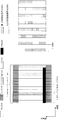
- FIG. 9 is a diagram illustrating a schematic configuration of SRS resource allocation and frequency hopping (FH).
- the horizontal axis is time, and the vertical axis is frequency.
- the left side of the figure shows an example of SRS resource allocation.
- 14 symbols are arranged in the time axis direction. Seven symbols correspond to one slot, and the length of one slot is 0.5 milliseconds (ms). Further, 14 symbols (corresponding to 2 slots) correspond to 1 subframe, and the length of 1 subframe is 1 millisecond.
- the SRS is arranged in the 14th symbol (also referred to as an SRS symbol).
- the SRS resource (bandwidth in the frequency axis direction) arranged in the 14th symbol is set in the base station apparatus according to the uplink system bandwidth and the transmission power of the mobile station apparatus. Further, the PRACH can be allocated with the bandwidth and the time symbol length being changed according to the type and format of the message to be transmitted.
- DM-RSs are arranged in the 4th and 11th symbols (also referred to as DM-RS symbols) when one subframe is composed of 14 symbols, and the DM-RS transmission bandwidth is the PUSCH transmission bandwidth. Matches the width.
- frequency hopping that changes the frequency position every time transmission is applied.
- the right side of the figure shows an example of SRS frequency hopping.
- SRS is transmitted every transmission period T.
- hopping is performed in the frequency direction every period T (that is, every time SRS is transmitted).
- the mobile station apparatus can apply frequency hopping when the hopping bandwidth, which is one of the SRS setting information, is set to a bandwidth wider than the SRS transmission bandwidth.
- FIG. 1 is a block diagram showing a schematic functional configuration of a base station apparatus 1 according to the present invention.
- the base station device 1 includes a transmission unit 101, a reception unit 103, a scheduling unit (base station side scheduling unit) 105, an upper layer 107, a channel estimation unit 108, and an antenna 109.
- the transmission unit 101 includes a data control unit 1011, a modulation unit 1013, and a wireless transmission unit 1015.
- the reception unit 103 includes a wireless reception unit 1031, a demodulation unit 1033, and a data extraction unit 1035.
- the data control unit 1011 inputs user data and control data, arranges control data on the PDCCH according to an instruction from the scheduling unit 105, and arranges transmission data and control data for the mobile station apparatus 3 on the PDSCH.
- the modulation unit 1013 performs signal processing such as data modulation, serial / parallel conversion of input signals, IFFT, CP insertion, and filtering, and generates a transmission signal.
- the radio transmission unit 1015 transmits the modulated data to the mobile station apparatus 3 via the antenna 109 after up-converting the modulated data to a radio frequency. Further, the transmission unit 101 includes the first to third control information in the PDCCH and transmits it to the mobile station apparatus 3 according to the instruction of the scheduling unit 105.
- the radio reception unit 1031 receives an uplink signal from the mobile station apparatus 3, down-converts it to a baseband signal, and outputs received data to the demodulation unit 1033.
- the data extraction unit 1035 confirms the correctness of the received data and notifies the scheduling unit 105 of the confirmation result. If the received data is correct, the data extraction unit 1035 separates the received data into user data and control data.
- the data extraction unit 1035 outputs the control data of the second layer such as downlink channel quality indication information and the success / failure of the downlink data (ACK / NACK) in the control data to the scheduling unit 105, and the other data
- the control data and user data of the third layer and the like are output to the upper layer 107. If the received data is in error, the data extraction unit 1035 stores the received data for combining with the retransmitted data, and performs a combining process when the retransmitted data is received.
- the scheduling unit 105 performs scheduling for arranging user data and control data on the PDSCH and PDCCH. In addition, the scheduling unit 105 instructs the transmission unit 101 to transmit an A-SRS transmission instruction included in the PDCCH (DCI format) according to an instruction from the upper layer 107.
- A-SRS transmission instruction included in the PDCCH DCI format
- the upper layer 107 includes a medium access control (MAC: Medium Access Control) layer, a radio link control (RLC: Radio Link Control) layer, a packet data convergence protocol (PDCP: Packet Data Convergence Protocol) layer, and a radio resource control (RRC: Radio). Resource (Control) layer processing. Since the upper layer 107 controls the processing units of the lower layer in an integrated manner, there is an interface between the upper layer 107, the scheduling unit 105, the channel estimation unit 108, the antenna 109, the transmission unit 101, and the reception unit 103. (However, not shown).
- MAC Medium Access Control
- RLC Radio Link Control
- PDCP Packet Data Convergence Protocol
- RRC Radio Resource Control
- the upper layer 107 has a radio resource control unit 1071 (also referred to as a control unit).
- the radio resource control unit 1071 manages various setting information, system information, paging control, communication state management of each mobile station device, mobility management such as handover, buffer status management for each mobile station device, Management of connection settings of cast and multicast bearers, management of mobile station identifiers (also referred to as UEID or RNTI (Radio Network Temporary Identifier)), and the like are performed. Further, the upper layer 107 transmits / receives information to another base station apparatus 1 and information to an upper node.
- UEID Radio Network Temporary Identifier
- the upper layer 107 sets and manages parameters such as SRS transmission bandwidth as SRS setting information, and notifies the scheduling unit 105 to notify the mobile station apparatus 3 of the SRS setting information included in the radio resource control signal. Instruct. Further, the SRS setting information may be notified by including not only the parameters of P-SRS but also the parameters of A-SRS (first A-SRS and second A-SRS, respectively). Further, the upper layer 107 instructs the scheduling unit 105 to transmit an A-SRS when it is desired to perform uplink channel measurement as necessary. Further, upper layer 107 determines the communication environment of mobile station apparatus 3 based on the channel estimation value of the uplink signal obtained from channel estimation section 108, and performs optimal resource allocation for PUSCH.
- parameters such as SRS transmission bandwidth as SRS setting information
- the SRS setting information may be notified by including not only the parameters of P-SRS but also the parameters of A-SRS (first A-SRS and second A-SRS, respectively).
- the upper layer 107 instructs the scheduling unit
- the upper layer 107 can instruct the mobile station apparatus 3 to perform optimal A-SRS transmission in consideration of the communication environment of the mobile station apparatus 3.
- -Outputs the scheduling information including information instructing transmission switching between the SRS and the second A-SRS.
- the scheduling unit 105 estimates the uplink channel state (wireless channel state) output from the channel estimation unit 108, requests for resource allocation from the mobile station device 3, Uplink transport format (transmission form, ie, physical resource block allocation and modulation scheme and code) for modulating each data based on usable PRB information, scheduling information input from higher layer 107, etc. Scheduling information used for uplink scheduling and generation of scheduling information.
- the scheduling information used for the uplink scheduling is output to the data control unit 1011. When the upper layer 107 is instructed to transmit the first or second A-SRS, the scheduling information is reset and output to the data control unit 1011.
- the scheduling unit 105 maps the downlink logical channel input from the higher layer 107 to the transport channel, and outputs it to the data control unit 1011. In addition, the scheduling unit 105 processes the control data and the transport channel acquired in the uplink input from the data extraction unit 1035 as necessary, maps them to the uplink logical channel, and outputs them to the upper layer 107. To do.
- the channel estimation unit 108 estimates an uplink channel state from the demodulation reference signal for demodulation of uplink data, and outputs the estimation result to the demodulation unit 1033. Further, in order to perform uplink scheduling, an uplink channel state is estimated from the sounding reference signal, and the estimation result is output to scheduling section 105.
- FIG. 2 is a block diagram showing a schematic functional configuration of the mobile station apparatus 3 of the present invention.
- the mobile station apparatus 3 includes a transmission unit 201, a reception unit 203, a scheduling unit 205, a reference signal generation unit 206, an upper layer 207, and an antenna 209.
- the transmission unit 201 includes a data control unit 2011, a modulation unit 2013, and a wireless transmission unit 2015.
- the reception unit 203 includes a wireless reception unit 2031, a demodulation unit 2033, and a data extraction unit 2035.
- User data and control data are input from the upper layer 207 to the data control unit 2011.
- the data control unit 2011 arranges the input data on the PUSCH or PUCCH according to an instruction from the scheduling unit 205.
- the modulation unit 2013 performs data modulation on PUSCH and PUCCH and outputs the data to the radio transmission unit 2015.
- the wireless transmission unit 2015 inserts the modulated data and the uplink reference signal into a discrete Fourier transform (DFT: Discrete Fourier Transform), subcarrier mapping, inverse fast Fourier transform (IFFT: Inverse Fast Fourier Transform), and CP (Cyclic Prefix).
- DFT discrete Fourier transform
- IFFT inverse fast Fourier transform
- CP Cyclic Prefix
- the radio reception unit 2031 receives the downlink signal from the base station apparatus 1, down-converts it to a baseband signal, and outputs the received signal to the demodulation unit 2033.
- the demodulator 2033 demodulates the received data.
- the data extraction unit 2035 separates the received data into user data and control data. Further, the data extraction unit 2035 outputs scheduling information, random access response messages, control data related to intermittent reception control, and other second layer control data to the scheduling unit 205, and outputs user data to the upper layer 207.
- the data extraction unit 2035 detects the code point of the control information included in the PDCCH (DCI format) and outputs it to the upper layer 207.
- the scheduling unit 205 analyzes the control data input from the data extraction unit 2035, generates uplink scheduling information, and performs data control to allocate user data and control data to PUSCH and PUCCH based on the scheduling information. Section 2011 is instructed.
- the scheduling unit 205 includes a reference signal control unit 2051.
- the reference signal control unit 2051 extracts SRS setting information based on the scheduling information transmitted from the base station apparatus 1. Also, transmission control is performed when SRS and PUSCH or PUCCH occur at the same timing, and SRS transmission control information is generated.
- the reference signal control unit 2051 outputs the SRS setting information and the SRS transmission control information to the reference signal generation unit 206.
- the SRS setting information is information for setting parameters such as SRS transmission bandwidth and transmission cycle.
- the SRS transmission control information is information indicating an SRS transmission control method when the SRS and other uplink channels (PUSCH, PUCCH) are allocated to the same subframe. For example, when SRS and PUCCH occur in the same subframe, this is information for instructing the mobile station apparatus 3 to perform a process of not transmitting SRS.
- the scheduling unit 205 determines the uplink buffer status input from the higher layer 207 and uplink scheduling information (transport format and HARQ retransmission) from the base station apparatus 1 input from the data extraction unit 2035. Information), and scheduling information for mapping the uplink logical channel input from the upper layer 207 to the transport channel and the uplink scheduling based on the scheduling information input from the upper layer 207, etc. Scheduling information to be generated is generated. Note that the information notified from the base station apparatus 1 is used for the uplink transport format. The scheduling information is output to the data control unit 2011.
- uplink scheduling information transport format and HARQ retransmission
- the scheduling unit 205 maps the uplink logical channel input from the higher layer 207 to the transport channel, and outputs it to the data control unit 2011.
- the scheduling unit 205 also outputs the CSI, CQI, PMI, RI, and CRC check confirmation results input from the data extraction unit 2035 input from the channel estimation unit 208 to the data control unit 2011.
- the scheduling unit 205 processes the control data and the transport channel acquired in the downlink input from the data extraction unit 2035 as necessary, maps them to the downlink logical channel, and outputs them to the upper layer 207. To do.
- the channel estimation unit 208 estimates the downlink channel state from the DL-RS to demodulate the downlink data, and outputs the estimation result to the demodulation unit 2033. Also, the channel estimation unit 208 notifies the base station apparatus 1 of the downlink channel state (radio channel state, CSI, CQI, PMI, RI) estimation result from the downlink reference signal to the downlink channel. The state is estimated, and the estimation result is output to the scheduling unit 205 as, for example, CSI, CQI, PMI, or RI.
- the reference signal generation unit 206 generates SRS (A-SRS, P-SRS) based on the SRS setting information and SRS transmission control information input from the reference signal control unit 2051, and outputs the SRS to the wireless transmission unit 2015.
- the upper layer 207 includes a medium access control (MAC: Medium Access Control) layer, a radio link control (RLC: Radio Link Control) layer, a packet data convergence protocol (PDCP: Packet Data Convergence Protocol) layer, and a radio resource control (RRC: Radio) Resource (Control) layer processing. Since the upper layer 207 controls the processing units of the lower layer in an integrated manner, there is an interface between the upper layer 207, the scheduling unit 205, the channel estimation unit 208, the antenna 209, the transmission unit 201, and the reception unit 203. (However, not shown).
- MAC Medium Access Control
- RLC Radio Link Control
- PDCP Packet Data Convergence Protocol
- RRC Radio Resource Control
- the upper layer 207 has a radio resource control unit 2071 (also referred to as a control unit).
- the radio resource control unit 2071 manages various setting information, system information, paging control, communication status management of the local station, mobility management such as handover, buffer status management, unicast and multicast bearer connection setting management
- the mobile station identifier (UEID) is managed.
- the upper layer 207 extracts SRS setting information from the radio resource control signal transmitted from the base station apparatus 1 and sets SRS parameters. Further, when an A-SRS transmission instruction is included from the received DCI format, scheduling information considering A-SRS transmission is reset and output to the scheduling section 205. Further, upper layer 207 sets the first A-SRS or the second A-SRS in accordance with the A-SRS transmission instruction from base station apparatus 1 and outputs the first A-SRS to scheduling section 205 as scheduling information.
- the base station apparatus 1 transmits the first sounding reference signal arranged in the physical uplink shared channel resource or is arranged in a resource different from the physical uplink shared channel resource.
- the mobile station apparatus 3 is notified of transmission control information for setting the mobile station apparatus 3 to transmit the second sounding reference signal, and the mobile station apparatus 3 is notified of the uplink grant including a sounding reference signal transmission instruction.
- the mobile station apparatus 3 receives the transmission instruction of the sounding reference signal included in the uplink grant and the transmission of the first sounding reference signal is set by the transmission control information
- the mobile station apparatus 3 receives the first sounding reference signal.
- the second sounding reference signal is transmitted to the base station apparatus 1.
- the base station apparatus 1 determines (controls) a radio resource where the A-SRS is arranged by a radio resource control signal (RRC signaling). That is, the base station apparatus 1 instructs the mobile station apparatus 3 to arrange and transmit the first A-SRS in the PUSCH resource allocated by the uplink grant using RRC signaling. be able to. Further, the base station device 1 arranges the second A-SRS for the mobile station device 3 in the set resource (independent of the PUSCH resource) and transmits it to the base station device 1.
- RRC signaling can be used to indicate. That is, the base station apparatus 1 transmits the A-SRS to the mobile station apparatus 3 by arranging it in the PUSCH resource or by arranging it in the set resource (independent of the PUSCH resource). Can be indicated using RRC signaling.
- the base station apparatus 1 determines (controls) a radio resource in which the A-SRS is arranged by a radio resource control signal (RRC signaling) according to a change in the communication environment of the mobile station apparatus 3. For example, when the base station apparatus 1 determines that the communication environment of the mobile station apparatus 3 has deteriorated, the base station apparatus 1 instructs the mobile station apparatus 3 to transmit the first A-SRS arranged using the PUSCH resource. When it is determined that the communication environment of the mobile station apparatus 3 has improved, the mobile station apparatus 3 is configured to transmit the second A-SRS having a wide transmission bandwidth in which parameters are set independently of the PUSCH. Can be directed to.
- RRC signaling radio resource control signal
- the base station apparatus 1 determines that the mobile station apparatus 3 is at the cell edge, the base station apparatus 1 instructs the mobile station apparatus 3 to transmit the first A-SRS arranged in the PUSCH resource.
- a parameter is set independently of PUSCH (located in a resource different from PUSCH).
- the mobile station apparatus 3 can be instructed to transmit SRS.
- the base station apparatus 1 determines in advance which A-SRS is used for transmission for each uplink component carrier for the mobile station apparatus 3 that performs communication using a plurality of uplink component carriers.
- the same A-SRS (either one of the first A-SRS or the second A-SRS) may be set for each mobile station apparatus 3.
- FIG. 3 is a diagram illustrating an example of a DCI format including an A-SRS transmission instruction in the first embodiment.
- DCI format uplink grant
- PDCCH format identification Flag for format 0 / format 1A differentiation
- frequency hopping flag Frequency hopping flag
- resource block allocation and hopping resource allocation Resource block assignment and hopping
- modulation and coding scheme and redundancy version Modulation and coding scheme and redundancy version
- NDI New Data Indicator
- TPC transmission power control command
- TPC transmission power control command
- TPC transmission power control command
- CQI transmission instruction CQI request: also called CQI request
- the mobile station device 3 when the A-SRS transmission instruction is included in the uplink grant, the mobile station device 3 performs the first A according to the radio resource control signal notified from the base station device 1. -Send the SRS or the second A-SRS to the base station apparatus 1. That is, when the field defined for the A-SRS transmission instruction included in the uplink grant is set to a predetermined value (for example, “1”), the mobile station device 3 The A-SRS is transmitted to the base station apparatus 1.
- a predetermined value for example, “1”.
- FIG. 4B shows an A-SRS transmission instruction method when the A-SRS transmission instruction information is not included in the DCI format.
- the mobile station apparatus 3 recognizes that an A-SRS transmission instruction has been notified, and A-SRS is transmitted to the station apparatus 1.
- CQI and A-SRS are set in the same subframe. Transmit to the base station apparatus 1.
- the mobile station apparatus 3 arranges CQI and UL-SCH data (Uplink Shared Channel data, transport block for UL-SCH) in the PUSCH, and sends it to the base station device 1 in the same subframe together with the A-SRS. Send.
- CQI and UL-SCH data Uplink Shared Channel data, transport block for UL-SCH
- the cyclic shift applied to the A-SRS may be the same as the P-SRS, or the cyclic shift of the DM-RS
- the information may be defined in association with each other, may be uniquely determined in advance by the system, may be notified from the base station apparatus 1 to the mobile station apparatus 3 all at once as broadcast information, or individually from the base station apparatus 1 The mobile station apparatus 3 may be notified.
- the number of transmissions of A-SRS (first A-SRS and second A-SRS, respectively) and a transmission timer are set in advance from the base station apparatus 1 and are transmitted to the mobile station apparatus 3 using a radio resource control signal or the like. When notified, the mobile station apparatus 3 transmits A-SRS to the base station apparatus 1 until the number of transmissions and the transmission timer expire.
- the parameters of the second A-SRS may be the same as those of the P-SRS, may be uniquely determined in advance by the system, or are transmitted from the base station apparatus 1 to the mobile station apparatus 3 as broadcast information. It may be notified all at once, or may be notified from the base station apparatus 1 to the individual mobile station apparatus 3. Different cyclic shifts may be applied to the first A-SRS and the second A-SRS. For example, the cyclic shift of the first A-SRS is set to the same cyclic shift as that of the DM-RS transmitted in the same subframe, and the cyclic shift of the second A-SRS is changed from the base station apparatus 1. You may notify with the radio
- the cyclic shifts of the first A-SRS and the second A-SRS are parameters applied to the cyclic shift of the DM-RS (for example, the cyclic shift index of the DM-RS, the cyclic shift index of the DM-RS, etc.). Different values may be applied individually in association with the click shift information), or the same value may be applied. That is, the base station apparatus 1 can set the cyclic shift of the first A-SRS and the cyclic shift of the second A-SRS in association with the parameters applied to the cyclic shift of the DM-RS.
- the mobile station apparatus 3 can uniformly (mechanically) set the cyclic shift applied to the first A-SRS and the second A-SRS from the parameters applied to the DM-RS. .
- the base station apparatus 1 when the base station apparatus 1 instructs the mobile station apparatus 3 to transmit the first sounding reference signal arranged in the physical uplink shared channel resource, the base station apparatus 1 includes a transmission instruction included in the uplink grant.
- the transmission instruction information is set to the second value. Set as a value.
- the base station apparatus 1 notifies the mobile station apparatus 3 of the uplink grant including the transmission instruction information set to the first value or the second value.
- the mobile station apparatus 3 transmits the first sounding reference signal to the base station apparatus 1, and the transmission instruction information included in the uplink grant.
- the second sounding reference signal is transmitted to the base station apparatus 1.
- the base station apparatus 1 can dynamically control the A-SRS transmission method of the mobile station apparatus 3 as necessary, and can perform optimal channel measurement. Efficient communication can be performed with the station apparatus 3.
- the base station apparatus 1 uses the A-SRS transmission instruction information to transmit to the mobile station apparatus 3 the first A-SRS arranged in the PUSCH resource allocated by the uplink grant. Can be instructed. Further, the base station device 1 arranges the second A-SRS for the mobile station device 3 in the set resource (independent of the PUSCH resource) and transmits it to the base station device 1.
- the A-SRS transmission instruction information can be used for instruction. That is, the base station apparatus 1 transmits the A-SRS to the mobile station apparatus 3 by arranging it in the PUSCH resource or by arranging it in the set resource (independent of the PUSCH resource). Can be instructed using the A-SRS transmission instruction information.
- FIG. 4 is an example of a DCI format including an A-SRS transmission instruction in the second embodiment.
- the DCI format shown in FIG. 6A has the same configuration as the DCI format shown in FIG. 3A, but the A-SRS transmission instruction information is composed of a plurality of bits of 2 bits or more. By configuring the A-SRS transmission instruction information with a plurality of bits, it is possible to dynamically switch the transmission instruction between the first A-SRS and the second A-SRS.
- (A) in the figure shows the configuration of control information when A-SRS transmission instruction (SRS activation) information is added to the DCI format.
- SRS activation A-SRS transmission instruction
- the A-SRS transmission instruction information is composed of 2 bits
- “00” is the A-SRS transmission stop
- “01” is the first A-SRS transmission
- “10” is the second A-SRS.
- the control information included in the DCI format is control information different from the control information shown in FIG. Recognize that there is.
- the control information other than the A-SRS transmission instruction information is the setting information (SRS configurations ⁇ ⁇ ⁇ ⁇ ⁇ for 2nd A-SRS) for instructing the second A-SRS parameters such as the transmission bandwidth and cyclic shift of the second A-SRS. Recognize that Thereby, it can be set to transmit the second A-SRS in which the parameter based on the setting information is set.
- the mobile station apparatus 3 can perform A-SRS transmission by dynamically switching between the first A-SRS and the second A-SRS.
- the second A-SRS parameter (SRS configurations for 2nd A-SRS) included in the setting information includes a transmission bandwidth (SRS transmission) when the mobile station device 3 transmits the second A-SRS. Bandwidth).
- the second A-SRS parameter includes a cyclic shift used to maintain orthogonality between the mobile station apparatuses 3 or between signals.
- the parameter of the second A-SRS includes information indicating the frequency position where the second A-SRS is arranged.
- the second A-SRS parameter includes the number of transmissions or the transmission stop time for completing the transmission of the second A-SRS.
- the second A-SRS parameter includes an antenna port (antenna index) for transmitting the second A-SRS.
- the second A-SRS parameter includes a multi-antenna simultaneous transmission flag indicating whether or not A-SRS transmission is performed using a plurality of antennas simultaneously as in MIMO.
- the second A-SRS parameter includes a TPC command (transmission power control information) for the second A-SRS. Also, which of these second A-SRS parameters is used may be uniquely determined in advance by the system, or from the base station apparatus 1 to the mobile station apparatus 3 as broadcast information. May be notified all at once, or may be notified from the base station apparatus 1 to the individual mobile station apparatuses 3.
- the base station apparatus 1 instructs the mobile station apparatus 3 to transmit the first sounding reference signal arranged in the physical uplink shared channel resource
- 1 bit included in the uplink grant When the mobile station apparatus 3 is instructed to transmit the second sounding reference signal arranged in a resource different from the physical uplink shared channel resource, the transmission grant information is set to a predetermined value.
- the included first control information is set at a predetermined code point.
- the base station apparatus 1 sets the transmission instruction of the sounding reference signal using the transmission instruction information or the first control information, and the transmission instruction information set to a predetermined value or the first code point set to a predetermined code point.
- the mobile station apparatus 3 By notifying the mobile station apparatus 3 of the uplink grant including the control information 1, the mobile station apparatus 3 is notified of the uplink grant including the transmission instruction of the sounding reference signal.
- the transmission instruction information included in the uplink grant indicates a sounding reference signal transmission instruction
- the mobile station apparatus 3 transmits the first sounding reference signal to the base station apparatus 1 and is included in the uplink grant.
- the first control information to be transmitted is a predetermined code point
- a second sounding reference signal is transmitted to the base station apparatus 1.
- the base station apparatus 1 notifies the mobile station apparatus 3 of the transmission instruction of the first A-SRS with 1-bit transmission instruction information (SRS activation for 1st A-SRS), and the second A-SRS transmission instruction is notified by the first control information which is a predetermined code point. That is, the base station device 1 uses the 1-bit transmission instruction information to transmit to the mobile station device 3 the first A-SRS arranged in the PUSCH resource allocated by the uplink grant. Can be instructed. Further, the base station device 1 arranges the second A-SRS for the mobile station device 3 in the set resource (independent of the PUSCH resource) and transmits it to the base station device 1.
- SRS activation for 1st A-SRS 1-bit transmission instruction information
- the first control information that is a predetermined code point can be used for the instruction.
- predetermined control information set to a predetermined value can be used for the instruction.
- predetermined control information first control information
- the base station apparatus Whether or not transmission of the second A-SRS is instructed by 1 is defined in advance by specifications or the like.
- the control information field other than the first control information may be used to indicate other control information.
- the base station apparatus 1 can assign the mobile station apparatus 3 as a second A-SRS parameter to a control information field other than the first control information.
- the second A-SRS parameter (SRS configurations for 2nd A-SRS) includes a transmission bandwidth (SRS transmission bandwidth) when the mobile station device 3 transmits the second A-SRS.
- the second A-SRS parameter includes a cyclic shift used to maintain orthogonality between the mobile station apparatuses 3 or between signals.
- the parameter of the second A-SRS includes information indicating the frequency position where the second A-SRS is arranged.
- the second A-SRS parameter includes the number of transmissions or the transmission stop time for completing the transmission of the second A-SRS.
- the second A-SRS parameter includes an antenna port (antenna index) for transmitting the second A-SRS.
- the second A-SRS parameter includes a multi-antenna simultaneous transmission flag indicating whether or not A-SRS transmission is performed using a plurality of antennas simultaneously as in MIMO.
- the second A-SRS parameter includes a TPC command (transmission power control information) for the second A-SRS.
- which of these second A-SRS parameters is used may be uniquely determined in advance by the system, or from the base station apparatus 1 to the mobile station apparatus 3 as broadcast information. May be notified all at once, or may be notified from the base station apparatus 1 to the individual mobile station apparatuses 3.
- the base station apparatus 1 dynamically changes parameters such as the transmission bandwidth, transmission timing, and cyclic shift of the second A-SRS according to the communication environment of the mobile station apparatus 3, Interference with other mobile station apparatuses 3 can be reduced, flexible SRS arrangement can be performed, and communication quality can be improved.
- unnecessary transmission of the second A-SRS can be reduced by controlling the transmission instruction of the second A-SRS using the first control information that is a predetermined code point with few false detections. It is possible to reduce the influence of interference on the SRS of another mobile station apparatus 3 due to the erroneous transmission of the second A-SRS.
- FIG. 5 is a diagram illustrating an example of a DCI format including an A-SRS transmission instruction according to the third embodiment.
- DCI format uplink grant
- PDCCH format identification Flag for format 0 / format 1A differentiation
- frequency hopping flag Frequency hopping flag
- resource block allocation and hopping resource allocation Resource block assignment and hopping
- modulation and coding scheme and redundancy version Modulation and coding scheme and redundancy version
- NDI New Data Indicator
- the mobile station device 3 when an A-SRS transmission instruction is set, the mobile station device 3 transmits PUSCH and A-SRS to the base station device 1 in the same subframe. That is, when the field defined for the A-SRS transmission instruction included in the uplink grant is set to “1”, for example, the mobile station device 3 uses the PUSCH and the ASCH in a certain subframe. -Both SRS are transmitted to the base station apparatus 1. At this time, if the CQI transmission instruction included in the uplink grant is also set (for example, the CQI request is set to “1”), the CQI and the A-SRS are transmitted in the same subframe. Transmit to the station apparatus 1.
- the mobile station apparatus 3 arranges CQI and UL-SCH data (Uplink Shared Channel data, transport block for UL-SCH) in the PUSCH, and sends it to the base station device 1 in the same subframe together with the A-SRS. Send.
- CQI and UL-SCH data Uplink Shared Channel data, transport block for UL-SCH
- the base station apparatus 1 can instruct the mobile station apparatus 3 to transmit only CQI (transmission of CQI without UL-SCH data, transmission of only uplink control information).
- the base station apparatus 1 instructs the mobile station apparatus 3 to transmit only CQI by setting predetermined information of the uplink grant to a predetermined value (setting a predetermined code point).
- the base station apparatus 1 sets the resource block arrangement, the MCS information, and the CQI request included in the uplink grant to predetermined values and notifies the mobile station apparatus 3 to the mobile station apparatus 3 with respect to the CQI. Can only instruct transmission.
- (B) of the figure shows a case where the frequency hopping flag, the resource block arrangement, and the hopping resource allocation information are set as predetermined code points as an example. That is, a case is shown where the first control information (predetermined information) is composed of a frequency hopping flag, a resource block arrangement, and hopping resource allocation information.
- the first control information is a predetermined code point
- the mobile station apparatus 3 transmits an A-SRS to the base station apparatus 1 without PUSCH. That is, when the frequency hopping flag, the resource block arrangement, and the hopping resource allocation information (first control information) defined in advance as the predetermined information are set to predetermined values, the mobile station device 3 In the frame, only the A-SRS is transmitted to the base station apparatus 1 without PUSCH.
- A-SRS transmission instruction information is defined in advance as control information included in the DCI format (uplink grant). Further, it is possible to issue an A-SRS transmission instruction using control information other than the A-SRS transmission instruction information.
- the first control information is a predetermined code point (predetermined value)
- the mobile station apparatus 3 recognizes that the transmission of the second A-SRS is instructed.
- the base station apparatus 1 can also reuse the A-SRS transmission instruction information as a field for indicating other control information.
- the mobile station device 3 can replace the control information that is not used in the first control information as other control information (for example, A-SRS setting information).
- the base station apparatus 1 when the base station apparatus 1 instructs the transmission of A-SRS by 1-bit transmission instruction information, the base station apparatus 1 transmits information (A-SRS) that instructs the transmission of the A-SRS included in the uplink grant.
- A-SRS information that instructs the transmission of the A-SRS included in the uplink grant.
- the base station apparatus 1 sets the information instructing transmission of A-SRS included in the uplink grant to “1” and notifies the mobile station apparatus 3 to the mobile station apparatus 3 with respect to A -It can instruct the transmission of SRS.
- the base station apparatus 1 sets the control information defined for instructing transmission of A-SRS to a predetermined value (for example, “1”) and notifies the mobile station apparatus 3 by The station apparatus 3 can be instructed to transmit A-SRS.
- a predetermined value for example, “1”
- the base station apparatus 1 does not transmit the A-SRS to the mobile station apparatus 3
- the information instructing the transmission of the A-SRS included in the uplink grant is set to “0”, for example. Then, the mobile station apparatus 3 is notified.
- the base station apparatus 1 indicates that the A-SRS transmission is instructed by control information (first control information) that is a predetermined code point (predetermined value).
- the base station apparatus 1 is included in the uplink grant.
- the base station apparatus 1 sets the frequency hopping flag, the resource block arrangement, and the hopping resource allocation information included in the uplink grant to predetermined values (for example, all fields are set to “1”), and then to the mobile station apparatus 3. By notifying, it is possible to instruct the mobile station apparatus 3 to transmit A-SRS.
- the base station apparatus 1 instructs the mobile station apparatus 3 to transmit A-SRS. Etc., and is known between the base station apparatus 1 and the mobile station apparatus 3 in advance. That is, for example, the base station apparatus 1 uses control information defined for a purpose other than instructing transmission of A-SRS (for example, frequency hopping flag, resource block arrangement, hopping resource allocation) as a predetermined value (for example, it is possible to instruct the mobile station apparatus 3 to transmit A-SRS by setting all fields to “1”) and notifying the mobile station apparatus 3.
- the base station apparatus 1 described above (for example, represented by 1 bit) in the predetermined information set to a predetermined value to instruct the mobile station apparatus 3 to transmit A-SRS. Control information defined for instructing transmission of A-SRS may be included.
- the base station apparatus 1 By instructing transmission of A-SRS with control information that is a predetermined code point, the base station apparatus 1 does not depend on the value set in the A-SRS transmission instruction information included in the uplink grant.
- the mobile station device 3 can be instructed to transmit only A-SRS.
- the mobile station apparatus 3 when the A-SRS transmission instruction is indicated by the 1-bit transmission instruction information in the uplink grant, the mobile station apparatus 3 bases the PUSCH and the first A-SRS in the same subframe. Transmit to the station apparatus 1.
- the mobile station device 3 receives, for example, the uplink grant. After 4 subframes from the subframe, the PUSCH is transmitted to the base station apparatus 1, and the second A-SRS is transmitted in the first cell-specific SRS subframe or mobile station apparatus-specific SRS subframe after the 4th subframe. Also good.
- the subframe for transmitting the second A-SRS may be uniquely determined in advance by the system, or may be notified from the base station apparatus 1 to the mobile station apparatus 3 all at once as broadcast information. Notification may be made from the base station apparatus 1 to the individual mobile station apparatus 3.
- the mobile station apparatus 3 indicates the A-SRS transmission instruction included in the uplink grant by using 1-bit transmission instruction information or first control information that is a predetermined code point. Regardless of the presence or absence of transmission, the first A-SRS and the second A-SRS can be dynamically switched and transmitted to the base station apparatus 1, and channel measurement in accordance with the communication environment can be performed.
- A-SRS when PUSCH transmission is not required, A-SRS can be transmitted without PUSCH, thereby reducing the influence of interference on other mobile station apparatuses 3.
- the mobile station apparatus 3 uses the CQI and the A-SRS. May be transmitted to the base station apparatus 1 in the same subframe, or may be transmitted in different subframes.
- the second A-SRS parameter when communication is performed using a plurality of uplink component carriers, the second A-SRS parameter may be set for each uplink component carrier. It may be set for each mobile station apparatus 3.
- the base station apparatus 1 can communicate with the communication environment (including communication quality, channel quality, communication state, channel state, and radio propagation path state) Or cell edge (cell edge)), and instructing the mobile station apparatus 3 to switch between the first A-SRS and the second A-SRS for transmission according to the number of mobile station apparatuses 3 in the cell. it can. For example, if the first A-SRS (in-band A-SRS) arranged in the PUSCH resource is transmitted in an environment with poor communication quality such as a cell edge, the channel measurement accuracy is improved.
- the communication environment including communication quality, channel quality, communication state, channel state, and radio propagation path state
- cell edge cell edge
- a second A-SRS (out-band A-SRS) having a wide transmission bandwidth arranged in a resource different from PUSCH is transmitted in an environment with good communication quality such as a cell center
- frequency selection scheduling is used. Communication quality can be improved. That is, efficient communication between the base station apparatus 1 and the mobile station apparatus 3 can be realized by dynamically switching the first A-SRS and the second A-SRS according to the communication environment or the like. .
- the program for realizing the control function may be recorded on a computer-readable recording medium, and the program recorded on the recording medium may be read by a computer system and executed.
- the “computer system” includes an OS and hardware such as peripheral devices.
- the “computer-readable recording medium” refers to a storage device such as a flexible medium, a magneto-optical disk, a portable medium such as a ROM or a CD-ROM, and a hard disk incorporated in a computer system.
- “computer-readable recording medium” means that a program is held dynamically for a short time, like a communication line when a program is transmitted via a network such as the Internet or a communication line such as a telephone line. It is also possible to include one that holds a program for a certain period of time, such as a volatile memory inside a computer system that becomes a server or client in that case.
- the program may be a program for realizing a part of the functions described above, and may be a program capable of realizing the functions described above in combination with a program already recorded in a computer system.
- part or all of the mobile station device 3 and the base station device 1 in the above-described embodiment may be realized as an LSI (Large Scale Integration) that is typically an integrated circuit.
- LSI Large Scale Integration
- Each functional block of the mobile station device 3 and the base station device 1 may be individually chipped, or a part or all of them may be integrated into a chip.
- the method of circuit integration is not limited to LSI, and may be realized by a dedicated circuit or a general-purpose processor.
- an integrated circuit based on the technology can also be used.
- Base station apparatus 3 Mobile station apparatus 101 Transmitter (base station side transmitter) 103 Receiver (base station side receiver) 105 Scheduling unit (base station side scheduling unit) 107 Upper layer 108 Channel estimation unit 109 Antenna 201 Transmitter (mobile station side transmitter) 203 Receiving unit (receiving unit on the mobile station side) 205 Scheduling unit 206 Reference signal generation unit 207 Upper layer 208 Channel estimation unit 209 Antenna 1011 Data control unit 1013 Modulation unit 1015 Radio transmission unit 1031 Radio reception unit 1033 Demodulation unit 1035 Data extraction unit 1071 Radio resource control unit 2011 Data control unit 2013 Modulation Unit 2015 wireless transmission unit 2031 wireless reception unit 2033 demodulation unit 2035 data extraction unit 2051 reference signal control unit 2071 radio resource control unit
Landscapes
- Engineering & Computer Science (AREA)
- Signal Processing (AREA)
- Computer Networks & Wireless Communication (AREA)
- Power Engineering (AREA)
- Mobile Radio Communication Systems (AREA)
Priority Applications (5)
| Application Number | Priority Date | Filing Date | Title |
|---|---|---|---|
| CN201180028595.6A CN102934506B (zh) | 2010-06-10 | 2011-05-30 | 无线通信系统、基站装置、移动站装置、无线通信方法及集成电路 |
| EP11792318.5A EP2582195B1 (en) | 2010-06-10 | 2011-05-30 | Wireless communication system, base station apparatus, mobile station apparatus, wireless communication method and integrated circuit |
| US13/702,620 US9232535B2 (en) | 2010-06-10 | 2011-05-30 | Wireless communication system, base station apparatus, mobile station apparatus, wireless communication method and integrated circuit |
| CA2801696A CA2801696C (en) | 2010-06-10 | 2011-05-30 | Wireless communication system, base station apparatus, mobile station apparatus, wireless communication method and integrated circuit |
| US14/958,595 US9876617B2 (en) | 2010-06-10 | 2015-12-03 | Wireless communication system, base station apparatus, mobile station apparatus, wireless communication method and integrated circuit |
Applications Claiming Priority (2)
| Application Number | Priority Date | Filing Date | Title |
|---|---|---|---|
| JP2010132630A JP5610861B2 (ja) | 2010-06-10 | 2010-06-10 | 移動局装置、基地局装置、無線通信システム、無線通信方法および集積回路 |
| JP2010-132630 | 2010-06-10 |
Related Child Applications (2)
| Application Number | Title | Priority Date | Filing Date |
|---|---|---|---|
| US13/702,620 A-371-Of-International US9232535B2 (en) | 2010-06-10 | 2011-05-30 | Wireless communication system, base station apparatus, mobile station apparatus, wireless communication method and integrated circuit |
| US14/958,595 Continuation US9876617B2 (en) | 2010-06-10 | 2015-12-03 | Wireless communication system, base station apparatus, mobile station apparatus, wireless communication method and integrated circuit |
Publications (1)
| Publication Number | Publication Date |
|---|---|
| WO2011155361A1 true WO2011155361A1 (ja) | 2011-12-15 |
Family
ID=45097969
Family Applications (1)
| Application Number | Title | Priority Date | Filing Date |
|---|---|---|---|
| PCT/JP2011/062380 Ceased WO2011155361A1 (ja) | 2010-06-10 | 2011-05-30 | 無線通信システム、基地局装置、移動局装置、無線通信方法および集積回路 |
Country Status (6)
| Country | Link |
|---|---|
| US (2) | US9232535B2 (enExample) |
| EP (1) | EP2582195B1 (enExample) |
| JP (1) | JP5610861B2 (enExample) |
| CN (1) | CN102934506B (enExample) |
| CA (1) | CA2801696C (enExample) |
| WO (1) | WO2011155361A1 (enExample) |
Cited By (4)
| Publication number | Priority date | Publication date | Assignee | Title |
|---|---|---|---|---|
| WO2013133193A1 (ja) * | 2012-03-09 | 2013-09-12 | シャープ株式会社 | 基地局、端末、通信方法および集積回路 |
| JP2013539268A (ja) * | 2010-08-13 | 2013-10-17 | 富士通株式会社 | 下り制御情報送信方法、受信方法及び装置、並びに端末、基地局及び通信システム |
| CN104685948A (zh) * | 2012-09-27 | 2015-06-03 | 夏普株式会社 | 终端、通信方法以及集成电路 |
| WO2021147088A1 (en) * | 2020-01-23 | 2021-07-29 | Qualcomm Incorporated | Scheduling reference signals for multiple carriers |
Families Citing this family (50)
| Publication number | Priority date | Publication date | Assignee | Title |
|---|---|---|---|---|
| KR101294815B1 (ko) * | 2009-05-15 | 2013-08-08 | 엘지전자 주식회사 | 무선 통신 시스템에서 사운딩 참조 신호 송신 방법 및 이를 위한 장치 |
| US10135595B2 (en) * | 2010-06-21 | 2018-11-20 | Telefonaktiebolaget L M Ericsson (Publ) | Uplink control information (UCI) mapping indicator for long term evolution (LTE) carrier aggregation |
| JP5009410B2 (ja) * | 2010-10-29 | 2012-08-22 | シャープ株式会社 | 移動局装置、無線通信方法および集積回路 |
| MX2014000958A (es) | 2011-07-27 | 2014-02-27 | Lg Electronics Inc | Metodo para transmitir una señal de referencia de enlace ascendente en un sistema multi - nodo y terminal que utiliza el mismo. |
| JP5783062B2 (ja) * | 2012-01-24 | 2015-09-24 | 富士通株式会社 | 無線装置、無線制御方法、及び無線制御プログラム |
| EP2819457B1 (en) * | 2012-02-20 | 2018-09-05 | Fujitsu Limited | Wireless station and communication control method |
| EP3651401B1 (en) | 2012-09-28 | 2021-06-09 | Huawei Technologies Co., Ltd. | Method and device for processing common search area |
| US9210670B2 (en) * | 2013-03-18 | 2015-12-08 | Samsung Electronics Co., Ltd. | Uplink power control in adaptively configured TDD communication systems |
| KR102364695B1 (ko) * | 2013-08-17 | 2022-02-18 | 엘지전자 주식회사 | 무선 통신 시스템에서 사운딩 참조 신호의 전송 전력 제어 방법 및 이를 위한 장치 |
| KR20150022476A (ko) | 2013-08-23 | 2015-03-04 | 삼성전자주식회사 | 디스플레이장치 및 그 제어방법 |
| US20150139001A1 (en) * | 2013-11-20 | 2015-05-21 | Feng Xue | Method and apparatus for beam identification in multi-antenna systems |
| EP3105878B1 (en) * | 2014-02-16 | 2019-04-03 | LG Electronics Inc. | Method and apparatus for transmitting uplink data in a wireless communication system |
| CN106576255B (zh) * | 2014-08-06 | 2021-03-23 | 三菱电机株式会社 | 通信系统 |
| CN111641485B (zh) | 2014-09-25 | 2023-06-02 | 株式会社Ntt都科摩 | 用户装置和发送方法 |
| EP4221377A1 (en) * | 2015-03-20 | 2023-08-02 | Ntt Docomo, Inc. | Terminal, base station, and communication method |
| EP3661107B1 (en) * | 2015-06-23 | 2021-07-28 | LG Electronics Inc. | Method and apparatus for transmitting a signal in a wireless communication system |
| US10390363B2 (en) | 2015-09-15 | 2019-08-20 | Telefonaktiebolaget Lm Ericsson (Publ) | Uplink scheduling in wireless communication networks |
| EP3375233B1 (en) * | 2015-09-24 | 2020-02-05 | Telefonaktiebolaget LM Ericsson (PUBL) | Technique for downlink control |
| KR102192250B1 (ko) * | 2016-03-27 | 2020-12-17 | 엘지전자 주식회사 | 무선 통신 시스템에서 상향링크 복조 참조 신호 송수신 방법 및 이를 위한 장치 |
| CN111740812B (zh) * | 2016-04-01 | 2022-09-20 | 中兴通讯股份有限公司 | 探测参考信号发送方法 |
| WO2017179859A1 (ko) * | 2016-04-10 | 2017-10-19 | 엘지전자 주식회사 | 무선 통신 시스템에서 상향링크 참조 신호를 전송하는 방법 및 장치 |
| EP3451774B1 (en) * | 2016-05-13 | 2020-11-04 | Huawei Technologies Co., Ltd. | Service data transmission method and user equipment |
| JP2019134199A (ja) * | 2016-06-03 | 2019-08-08 | シャープ株式会社 | 端末装置、基地局装置、通信方法、および、集積回路 |
| US10952210B2 (en) * | 2016-06-10 | 2021-03-16 | Qualcomm Incorporated | Reference signal presence and/or bandwidth determination in narrowband systems |
| US10314037B2 (en) * | 2016-07-08 | 2019-06-04 | Qualcomm Incorporated | Latency reduction techniques in wireless communications |
| US11140715B2 (en) | 2016-10-26 | 2021-10-05 | Qualcomm Incorporated | Waveform-dependent random access channel procedure |
| KR102402873B1 (ko) * | 2017-03-16 | 2022-05-30 | 베이징 시아오미 모바일 소프트웨어 컴퍼니 리미티드 | 절삭된 버퍼 상태 보고 |
| WO2018170673A1 (zh) * | 2017-03-20 | 2018-09-27 | Oppo广东移动通信有限公司 | 传输数据的方法、终端设备和网络设备 |
| CN108633036B (zh) * | 2017-03-24 | 2023-09-01 | 中兴通讯股份有限公司 | 一种控制信息传输方法及装置 |
| KR102247028B1 (ko) | 2017-05-04 | 2021-04-29 | 엘지전자 주식회사 | 무선 통신 시스템에서 상향링크 송수신 방법 및 이를 위한 장치 |
| CA3063213C (en) | 2017-05-04 | 2022-03-01 | Guangdong Oppo Mobile Telecommunications Corp., Ltd. | Method for determining transmission parameters of uplink signal, terminal and network device |
| JP2019004320A (ja) * | 2017-06-15 | 2019-01-10 | シャープ株式会社 | 基地局装置、端末装置およびその通信方法 |
| HUE063480T2 (hu) * | 2017-07-31 | 2024-01-28 | Ntt Docomo Inc | Terminál, rádiókommunikációs eljárás, bázisállomás és rendszer |
| US11233676B2 (en) * | 2017-08-11 | 2022-01-25 | Apple Inc. | Control signaling for sounding reference signal (SRS) |
| JP2021502009A (ja) * | 2017-09-29 | 2021-01-21 | オッポ広東移動通信有限公司Guangdong Oppo Mobile Telecommunications Corp., Ltd. | 無線通信方法及び装置 |
| KR102109412B1 (ko) * | 2018-02-14 | 2020-05-12 | 엘지전자 주식회사 | 무선 통신 시스템에서 무선 신호 송수신 방법 및 장치 |
| CN108260217B (zh) * | 2018-03-05 | 2024-06-04 | 中兴通讯股份有限公司 | 一种信息传输的方法、装置和通信节点 |
| US11323169B2 (en) * | 2018-03-08 | 2022-05-03 | Qualcomm Incorporated | Simultaneous uplink transmissions using spatial multiplexing |
| US11089582B2 (en) * | 2018-04-05 | 2021-08-10 | Huawei Technologies Co., Ltd. | Method and system for downlink control information payload size determination |
| BR112020020298A2 (pt) * | 2018-04-05 | 2021-01-12 | Ntt Docomo, Inc. | Terminal, estação base e método de radiocomunicação |
| US11490363B2 (en) * | 2018-04-18 | 2022-11-01 | Google Llc | User device-initiated bandwidth request |
| JP7366889B2 (ja) * | 2018-05-21 | 2023-10-23 | 株式会社Nttドコモ | 端末、無線通信方法、基地局及びシステム |
| US12021662B2 (en) * | 2018-09-28 | 2024-06-25 | Qualcomm Incorporated | Aperiodic sounding reference signal (A-SRS) configuration |
| KR102437503B1 (ko) * | 2019-02-08 | 2022-08-29 | 엘지전자 주식회사 | 무선 통신 시스템에서 사운딩 참조 신호를 전송하는 방법 및 이를 위한 장치 |
| EP3952472A4 (en) * | 2019-03-28 | 2022-11-23 | Ntt Docomo, Inc. | Base station device and user equipment |
| WO2020230863A1 (ja) * | 2019-05-15 | 2020-11-19 | 株式会社Nttドコモ | ユーザ端末及び無線通信方法 |
| CN114731257B (zh) * | 2020-01-10 | 2024-06-11 | 华为技术有限公司 | 上行信道解调方法和上行信道解调装置 |
| WO2021158025A1 (ko) | 2020-02-04 | 2021-08-12 | 엘지전자 주식회사 | 무선 통신 시스템에서 상향링크 채널 반복 전송 방법 및 장치 |
| WO2021159472A1 (en) * | 2020-02-14 | 2021-08-19 | Qualcomm Incorporated | Beyond-bandwidth part (bwp) sounding reference signal (srs) transmissions |
| WO2024046563A1 (en) * | 2022-08-31 | 2024-03-07 | Telefonaktiebolaget Lm Ericsson (Publ) | Phase shifted srs and pusch transmission across prb |
Family Cites Families (11)
| Publication number | Priority date | Publication date | Assignee | Title |
|---|---|---|---|---|
| MX2010007510A (es) * | 2008-01-08 | 2010-10-25 | Nokia Siemens Networks Oy | Arreglo de señal de referencia sonora. |
| US20090316676A1 (en) * | 2008-06-18 | 2009-12-24 | Nokia Corporation | Method and Apparatus for Coupled Sounding |
| CN101651469B (zh) * | 2008-08-15 | 2013-07-24 | 三星电子株式会社 | 用于lte系统中发送上行监测参考符号的跳频方法 |
| CN101662764B (zh) * | 2008-08-29 | 2011-12-28 | 联想(北京)有限公司 | 发射侦听参考信号的方法和系统 |
| EP2335360B1 (en) | 2008-09-26 | 2017-11-08 | Samsung Electronics Co., Ltd. | Apparatus and methods for supporting transmission of sounding reference signals with multiple antennas |
| KR101306735B1 (ko) * | 2008-10-15 | 2013-09-11 | 엘지전자 주식회사 | 복수개의 안테나를 이용한 사운딩 기준 신호 시퀀스 전송 방법 |
| CN101404817B (zh) * | 2008-11-24 | 2010-09-29 | 华为技术有限公司 | Srs带宽配置的方法、系统及装置 |
| JP5555763B2 (ja) * | 2009-03-17 | 2014-07-23 | インターデイジタル パテント ホールディングス インコーポレイテッド | サウンディング参照信号(srs)送信の電力制御のための方法および機器 |
| ES2903248T3 (es) * | 2009-11-02 | 2022-03-31 | Nokia Solutions & Networks Oy | Configuración de señal de referencia de sondeo |
| EP2793420B1 (en) * | 2010-01-07 | 2019-05-29 | Samsung Electronics Co., Ltd | User equipment, base station, and method for enhancing features of uplink reference signals |
| US8848520B2 (en) * | 2010-02-10 | 2014-09-30 | Qualcomm Incorporated | Aperiodic sounding reference signal transmission method and apparatus |
-
2010
- 2010-06-10 JP JP2010132630A patent/JP5610861B2/ja not_active Expired - Fee Related
-
2011
- 2011-05-30 CA CA2801696A patent/CA2801696C/en active Active
- 2011-05-30 US US13/702,620 patent/US9232535B2/en not_active Expired - Fee Related
- 2011-05-30 CN CN201180028595.6A patent/CN102934506B/zh active Active
- 2011-05-30 EP EP11792318.5A patent/EP2582195B1/en active Active
- 2011-05-30 WO PCT/JP2011/062380 patent/WO2011155361A1/ja not_active Ceased
-
2015
- 2015-12-03 US US14/958,595 patent/US9876617B2/en active Active
Non-Patent Citations (3)
| Title |
|---|
| CATT: "SRS enhancements for LTE-A UL transmission", 3GPP TSG RAN WG1 MEETING #59BIS, RL-100075, 22 January 2010 (2010-01-22), pages 1 - 6, XP050417818 * |
| MOTOROLA: "LTE-A Dynamic Aperiodic SRS - Triggering, Duration, Timing, and Carrier Aggregation", 3GPP TSG RAN WG1 MEETING #61, R1-103187, 10 May 2010 (2010-05-10) - 14 May 2010 (2010-05-14), pages 1 - 4, XP050420236 * |
| See also references of EP2582195A4 * |
Cited By (7)
| Publication number | Priority date | Publication date | Assignee | Title |
|---|---|---|---|---|
| JP2013539268A (ja) * | 2010-08-13 | 2013-10-17 | 富士通株式会社 | 下り制御情報送信方法、受信方法及び装置、並びに端末、基地局及び通信システム |
| KR101450486B1 (ko) | 2010-08-13 | 2014-10-13 | 후지쯔 가부시끼가이샤 | 다운링크 제어 정보 전송 방법 및 장치, 다운링크 제어 정보 수신 방법 및 장치, 단말기, 기지국 및 통신 시스템 |
| WO2013133193A1 (ja) * | 2012-03-09 | 2013-09-12 | シャープ株式会社 | 基地局、端末、通信方法および集積回路 |
| CN104685948A (zh) * | 2012-09-27 | 2015-06-03 | 夏普株式会社 | 终端、通信方法以及集成电路 |
| EP2903374A4 (en) * | 2012-09-27 | 2016-06-08 | Sharp Kk | END DEVICE, COMMUNICATION PROCESS AND INTEGRATED CIRCUIT |
| WO2021147088A1 (en) * | 2020-01-23 | 2021-07-29 | Qualcomm Incorporated | Scheduling reference signals for multiple carriers |
| US12438672B2 (en) | 2020-01-23 | 2025-10-07 | Qualcomm Incorporated | Scheduling reference signals for multiple carriers |
Also Published As
| Publication number | Publication date |
|---|---|
| JP5610861B2 (ja) | 2014-10-22 |
| CN102934506B (zh) | 2017-04-12 |
| US9876617B2 (en) | 2018-01-23 |
| CN102934506A (zh) | 2013-02-13 |
| JP2011259258A (ja) | 2011-12-22 |
| US9232535B2 (en) | 2016-01-05 |
| CA2801696C (en) | 2018-10-02 |
| CA2801696A1 (en) | 2011-12-15 |
| US20160156442A1 (en) | 2016-06-02 |
| EP2582195B1 (en) | 2018-05-16 |
| US20130121280A1 (en) | 2013-05-16 |
| EP2582195A4 (en) | 2016-03-09 |
| EP2582195A1 (en) | 2013-04-17 |
Similar Documents
| Publication | Publication Date | Title |
|---|---|---|
| JP5610861B2 (ja) | 移動局装置、基地局装置、無線通信システム、無線通信方法および集積回路 | |
| JP5538930B2 (ja) | 移動局装置、基地局装置、無線通信システムおよび無線通信方法 | |
| CN102860074B (zh) | 移动通信系统、基站装置、移动站装置以及通信方法 | |
| JP7100969B2 (ja) | 端末装置および基地局装置 | |
| JP6677642B2 (ja) | 端末装置、通信方法、および、集積回路 | |
| JP2017085188A (ja) | 端末装置、基地局装置および通信方法 | |
| JP2019054305A (ja) | 基地局装置、端末装置および通信方法 | |
| JPWO2015060433A1 (ja) | 端末装置、基地局装置、端末装置における方法、及び基地局装置における方法 | |
| JP6635267B2 (ja) | 端末装置、および、通信方法 | |
| JP6639395B2 (ja) | 端末装置、通信方法、および、集積回路 | |
| JP6541008B2 (ja) | 端末装置、および、通信方法 | |
| JP2012034145A (ja) | 移動通信システム、基地局装置、移動局装置、および、通信方法 | |
| JP2012080328A (ja) | 移動局装置、無線通信システムおよび無線通信方法 | |
| EP3021631B1 (en) | Terminal apparatus, base station apparatus, integrated circuit, and communication method | |
| JP5530254B2 (ja) | 移動局装置、基地局装置、無線通信システム、無線通信方法および集積回路 | |
| JP2012005035A (ja) | 移動局装置、基地局装置、無線通信システム、無線通信方法および集積回路 | |
| JP6128692B2 (ja) | 移動局装置、基地局装置および通信方法 | |
| WO2011102181A1 (ja) | 無線通信システム、基地局装置、移動局装置および無線通信方法 | |
| JP5756546B2 (ja) | 移動局装置、基地局装置および通信方法 | |
| JP2015095668A (ja) | 端末装置、基地局装置および通信方法 | |
| JP2019054304A (ja) | 基地局装置、端末装置および通信方法 | |
| WO2019167785A1 (ja) | 通信装置および通信方法 | |
| JP2014180053A (ja) | 移動局装置、および通信方法 |
Legal Events
| Date | Code | Title | Description |
|---|---|---|---|
| WWE | Wipo information: entry into national phase |
Ref document number: 201180028595.6 Country of ref document: CN |
|
| 121 | Ep: the epo has been informed by wipo that ep was designated in this application |
Ref document number: 11792318 Country of ref document: EP Kind code of ref document: A1 |
|
| DPE1 | Request for preliminary examination filed after expiration of 19th month from priority date (pct application filed from 20040101) | ||
| WWE | Wipo information: entry into national phase |
Ref document number: 2011792318 Country of ref document: EP |
|
| ENP | Entry into the national phase |
Ref document number: 2801696 Country of ref document: CA |
|
| NENP | Non-entry into the national phase |
Ref country code: DE |
|
| WWE | Wipo information: entry into national phase |
Ref document number: 13702620 Country of ref document: US |