WO2011155045A1 - 情報処理装置 - Google Patents
情報処理装置 Download PDFInfo
- Publication number
- WO2011155045A1 WO2011155045A1 PCT/JP2010/059865 JP2010059865W WO2011155045A1 WO 2011155045 A1 WO2011155045 A1 WO 2011155045A1 JP 2010059865 W JP2010059865 W JP 2010059865W WO 2011155045 A1 WO2011155045 A1 WO 2011155045A1
- Authority
- WO
- WIPO (PCT)
- Prior art keywords
- packet
- information processing
- control unit
- processing apparatus
- arbitration
- Prior art date
- Legal status (The legal status is an assumption and is not a legal conclusion. Google has not performed a legal analysis and makes no representation as to the accuracy of the status listed.)
- Ceased
Links
Images







Classifications
-
- H—ELECTRICITY
- H04—ELECTRIC COMMUNICATION TECHNIQUE
- H04L—TRANSMISSION OF DIGITAL INFORMATION, e.g. TELEGRAPHIC COMMUNICATION
- H04L12/00—Data switching networks
- H04L12/28—Data switching networks characterised by path configuration, e.g. LAN [Local Area Networks] or WAN [Wide Area Networks]
- H04L12/40—Bus networks
Definitions
- the present invention relates to a body-mounted device such as a power assist suit.
- a body-mounted device such as a power assist suit performs a desired operation from a state outside the device, a sensor that senses a state outside the device such as the wearer's body and the environment where the device is placed, an actuator that moves a joint, and the like. It comprises a control unit for determining and determining a method for controlling the actuator and assisting the wearer's physical function, and a packet router for communicating them.
- Patent Document 1 as a specific example of a layered network, a priority is given to a packet to be transferred, and different routing is performed on packets having the same network address according to the priority.
- a technique for providing a line or a detour and controlling a bandwidth and a delay time for data transfer is disclosed.
- the transfer route that requires real-time characteristics changes at short intervals in the wearer's series of actions.
- packet transfer that requires real-time performance must be performed between the right arm and left foot when the left foot is moved forward and between the left arm and right foot when the right foot is moved forward.
- some functions can be performed in the event of a sudden emergency such as when the wearer or device falls or collides with an obstacle. Even at the expense, you need to be passive with your left and right hands. Therefore, it is necessary to set the synchronization between the left and right arm devices with the highest priority, and accordingly, communication between them must be performed with the highest priority.
- the network arbitration method cannot be dynamically changed according to the state outside the apparatus.
- the network address to be preferentially transferred (a pair of a transmission side address and a reception side address) could not be changed.
- the control command for switching the arbitration table is also transferred through the normal transfer route.
- the packet router did not accept this control command and was unable to switch with the highest priority. For this reason, when an emergency situation occurs and the route for which real-time property is to be guaranteed changes suddenly, the network arbitration method cannot be switched in time, and real-time property cannot be guaranteed.
- a global packet router having a local packet router, a plurality of packet transmission units, and a plurality of packet reception units, mediating communication between the plurality of packet transmission units and the plurality of packet communication units, and controlling the global packet router
- a control unit that connects the global packet router and the control unit without going through the packet receiver, and each of the plurality of packet transmitters and each of the plurality of packet receivers includes a plurality of paths.
- the control unit is configured to determine whether the information processing device is in the first state or the information processing device is different from the first state based on information outside the information processing device obtained through the plurality of actuators.
- the control unit switches the setting of the global packet router via a route.
- FIG. 1 shows an overall view of a body-mounted device that is worn on the body and assists the movement according to the intention of the wearer.
- the body-mounted device includes a left foot device 101, a right foot device 102, a left arm device 103, a right arm device 104, a torso device 105, and a head device 106.
- Fig. 2 shows a network of body-worn devices.
- the network of the body wearing device includes a left foot local network 201, a right foot local network 202, a left arm local network 203, a right arm local network 204, a torso local network 205, a head local network 206, a global control unit 207, It consists of a packet router 208 that connects them. Further, a path 209 different from a normal communication path is provided between the global control unit and the packet router.
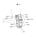
- FIG. 3 shows a foot device
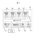
- FIG. 4 shows a foot local network.
- the local network other than the foot is omitted, for example, other local networks such as the arm device and the arm local network 300, the head device and the head local network have the same configuration. It can be implemented.
- the left foot device 101 and the right foot device 102 are symmetrical, and each has a thigh outer frame 301 that is in close contact with the thigh outer side, a thigh inner frame 302 that is in close contact with the thigh inner side, and a shin part that is in close contact with the thigh outer side.
- the foot has a foot packet router 313 for connecting the knee joint motor unit, knee joint angle sensor unit, acceleration sensor unit, and foot local control unit.
- each local network has a plurality of sensor units, a plurality of actuator units (for example, motor units), and a local packet router to which these are connected.
- the local packet router mediates communication from a plurality of sensors or communication to a plurality of actuators.
- FIG. 5 shows the body part device
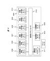
- FIG. 6 shows the body part network 600.
- the torso device has a chest frame 601 that is in close contact with the chest and a back frame 602 that is in close contact with the back, and further connects the chest frame, the back frame, the left thigh inner frame, and the left thigh outer frame.
- a left hip joint motor unit 603 having a movable range in the direction of bending the left hip joint, and a left hip joint angle sensor unit 604 for detecting a bent angle of the joint, and further, a chest frame, a back frame, and an inner right thigh
- the frame includes a right hip joint motor unit 605 that connects the frame and the right thigh outer frame and has a movable range in the direction of bending the right hip joint, and a right hip joint angle sensor unit 606 that detects a bent angle of the joint.
- the torso device further includes a chest acceleration sensor unit 607 and a chest infrared sensor unit 608 attached to the chest frame, and a back acceleration sensor unit 609 and a back infrared sensor unit 610 attached to the back frame.
- the trunk unit apparatus includes a trunk unit local control unit 611 that controls the trunk unit.
- the torso device includes the left hip joint motor unit, the left hip joint angle sensor unit, the right hip joint motor unit, the right hip joint angle sensor unit, the left shoulder joint motor unit, the left shoulder joint angle sensor unit, and the right shoulder joint.
- a body packet router 612 for connecting a motor unit, a right shoulder joint angle sensor unit, a chest acceleration sensor unit, a chest infrared sensor unit, a back acceleration sensor unit, a back infrared sensor unit, and a body local control unit is provided. Have.
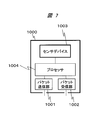
- FIG. 7 shows the configuration of a sensor unit, which is one of the above-described components.
- the sensor unit 1000 includes a packet transmission unit 1001 that transmits a packet to the packet router, a packet reception unit 1002 that receives the packet, a sensor device 1003, and a processor 1004 that controls the operation thereof.
- FIG. 8 shows the configuration of a motor unit, which is one of the above-described components.
- the motor unit 1100 includes a packet transmission unit 1101 that transmits a packet to the packet router, a packet reception unit 1102 that receives the packet, a motor 1103, and a processor 1104 that controls the operation thereof.
- FIG. 9 shows the configuration of the local control unit, which is one of the components.
- the local control unit 1200 includes a packet transmission unit 1201 that transmits packets to the packet router, a packet reception unit 1202 that receives packets, a processor 1203 that controls them, and a ROM 1204 and a RAM 1205 that are accessed by the processor through an internal bus.
- the packet transmission unit 1201 that transmits packets to the packet router
- a packet reception unit 1202 that receives packets
- a processor 1203 that controls them
- ROM 1204 and a RAM 1205 that are accessed by the processor through an internal bus.
- FIG. 10 shows the configuration of the global control unit, which is one of the components.
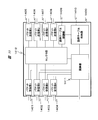
- the global control unit 1300 includes a packet transmission unit 1301 that transmits packets to the packet router, a packet reception unit 1302 that receives packets, a processor 1303 that controls them, a ROM 1304 and a RAM 1305 that the processor accesses via an internal bus, and a hard disk drive 1306, a status register 1307, and a basic operation table 1308.
- the status register 1307 can assert an arbitration table selection signal to the arbitration unit via the path 1309 (and the path 1507 in FIG. 12 described later) according to the value stored in the status register.
- the route from the status register 1307 of the global control unit to the arbitration unit of the global packet router via the route 1309 and the route 1507 indicates the “route 209 different from the normal route” described in FIG.
- the control unit in the present embodiment determines that the apparatus is in the second state (abnormal state) different from the first state (normal state)
- this “path 209 different from the normal path” By this, it becomes possible to switch the setting of the global packet router.
- Whether the sensor is normal or abnormal is determined by comparing external information from the sensor with a predetermined threshold value.
- the global control unit has a status register connected to the path, and writes a first value (for example, 1) to the status register when an abnormality is determined.
- a first value for example, 1
- the different paths described above are further characterized in that they have a smaller bit width and are not subject to arbitration for normal communication performed via the packet transmission unit 1301 and the packet reception unit 1302. This is because when an abnormality occurs, it is necessary to promptly notify the mediation unit to that effect, and the configuration concerned is the best for that purpose.
- FIG. 11 shows the configuration of a global packet router, which is one of the components.
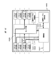
- the global packet router 1400 includes a plurality of packet receiving units 1401 to 1404, a plurality of packet transmitting units 1405 to 1408, an arbitration table control unit 1409, an arbitration table storage unit 1410, and a plurality of packet receiving units receiving packets simultaneously. And a selector 1412 that selects a packet transferred from the packet receiver to the packet transmitter or the arbitration table controller based on the arbitration performed by the arbitrator. .
- the packet receiving unit and the packet transmitting unit make a packet transfer in pairs.
- the packet receiver of the global packet router is connected to the packet transmitters of other local packet routers, sensor units, motor units, or control units.
- the connection relationship is fixed, and the transfer from an arbitrary packet transmission unit to the packet reception unit is realized by a global packet router.
- the packet receiving unit When the packet receiving unit receives a packet from the connected opposite device, the packet receiving unit transmits a transmission request and a pair of the source address and the destination address of the packet toward the arbitration unit (1501, 1502).
- the arbitration unit selects the packet transmitting unit to which the packet is to be transferred from the destination address, and the selector A selection signal is output to the unit (1504).
- the arbitration unit checks whether the address pair is registered in the arbitration table. In order to confirm, the address pair is output to the arbitration table storage unit.
- the arbitration table storage unit sets the priority registered in the table when the received address pair is registered in the arbitration table, and the initial value of priority 2 when not registered in the arbitration unit. Output (1503).
- the arbitration unit reads all the priorities for a plurality of the address pairs, and gives a bus right to the packet having the address pair with the highest read priority.
- a bus right is given to the packet by a round robin method in which a packet to be transferred is selected so that a packet that has been transferred immediately before is not transferred.
- the arbitration unit outputs a selection signal to the selector unit so that the packet having the bus right is transferred (1504). For example, if the packet having the address pair is stored in the packet receiver 1 and is to be routed to the packet transmitter 3, the packet is transferred from the packet receiver 1 to the packet transmitter 3. (1505) A select signal is output so as to switch the selector. At this time, the packets stored in the remaining packet receivers that have requested transfer at the same time are not transferred and are in a waiting state (1506).
- the arbitration unit When the arbitration unit performs arbitration during the period when the arbitration table selection signal is not asserted, it reads the arbitration table 1 in the arbitration table storage unit, and when performing arbitration during the period when the arbitration table selection signal is asserted, stores the arbitration table.
- the mediation table 2 of the department is read (1507).
- the case where the arbitration table selection signal is asserted is a case where an abnormality determination is made by the global control unit.
- the arbitration table 2 it is possible to instantaneously realize synchronous communication corresponding to the abnormal state.
- FIG. 12 also shows that the path 1507 is not subject to arbitration by the arbitration unit and the selector, and when an abnormality determination is made by the global control unit, it is possible to instantaneously shift to communication corresponding to the abnormal state.
- the global control unit When the global control unit tries to set the arbitration method of the packet router, the global control unit transmits a packet describing the arbitration table to the arbitration table control unit through a normal packet transfer path (1601). The arbitration table control unit that has received the packet rewrites the arbitration table storage unit based on the received packet (1602).
- the arbitration table entry consists of a source address, destination address, and priority.
- the source address and the destination address are each 12 bits, and are uniquely given to each network node connected to the network.
- the first 4 bits of the address of each network node are made common to each subnetwork.
- the upper 4 bits of the global control unit are 0000
- the foot network is 1XXX (X is 0 or 1)
- the right arm network is 0100
- the left arm network is 0101.
- the control unit sets the lower 2 bits of the address to 00
- the actuator sets the lower 2 bits of the address to 01
- the sensor sets the lower 2 bits of the address to 10.
- each entry of the arbitration table 1 in FIG. 14 is (1) packet transfer (control) from the global control unit has a priority of 5, and (2) global control from the left and right foot network. Transfer to the unit indicates priority 4, and (3) Transfer from the left and right arm network to the global control unit indicates priority 3.
- entries in the arbitration table 2 (arbitration table in an abnormal state) have (1) transfer priority from the left arm sensor to the right arm actuator is 7, and (2) transfer from the right arm sensor to the left arm actuator, respectively. (3) The priority of the communication between the left and right arm networks is 6, and (4) the transfer from the global control unit is the priority 5.
- the communication from the global control unit to each network node is prioritized in the arbitration table in the normal state. This is to directly control each unit. However, in the arbitration table in the abnormal state, the communication between the left and right arms is prioritized over the transfer from the global control unit to each network node. This is to realize cooperation between the left and right arm networks and direct operation without the control of the global control unit.
- the global packet router has the arbitration table 1 and the arbitration table 2, and selects the arbitration table 2 when an abnormality is notified from the global control unit via the path 1507.
- the arbitration table 1 is a communication mode that prioritizes control from the global control unit to each local control unit, that is, prioritizes centralized control during normal times.
- the arbitration table 2 is an emergency communication mode in which synchronous communication between local packet routers is given priority over control from the center.
- the global control unit starts a basic motion determination task at regular intervals.
- Each sensor transmits a packet storing the sensor value to the global control unit when the sensor value changes for a certain time or exceeds a preset value.
- the global control unit receives each sensor information (S001), and uses the sensor information to refer to the basic motion determination table to determine the current motion of the body wearing device and the wearer (S002). For example, basic operations such as sitting, standing, walking, raising arms are discriminated. Furthermore, in the case of walking, it is possible to subdivide the operation into the operation of raising the right foot, the operation of raising the right foot forward, the operation of raising the left foot, and the operation of raising the left foot forward.
- the global control unit changes various settings corresponding to the determined basic operation in the following procedure (S003).
- the arbitration table is rewritten (S004). For example, in the basic motion determination, if it is determined that the left foot moves forward, it is necessary to coordinate the motion of the left foot and the right hand, so that the packets communicated between the left foot network and the right arm network The global control unit rewrites the arbitration table of the packet router so that the priority becomes higher.
- a threshold value of sensor information is set (S005).
- the acceleration or the tilt of the sensor device, or the variation per unit time of the acceleration or the tilt is set as the threshold value of the sensor alone.
- the global control unit determines that the state outside the apparatus is a normal state.
- the abnormal condition routine when the sensor information received by the global control unit exceeds the threshold in the combination specified in advance.
- the abnormal state refers to a case where each sensor in a combination including a single sensor or a plurality of sensors designated in advance exceeds a set threshold value.
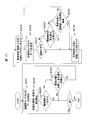
- the abnormal state routine is shown in FIG.
- 1 is set in the status register (S101).
- S102 a set threshold value
- S103 a predetermined time elapses after transition to the abnormal state
- S104 a predetermined time elapses after transition to the abnormal state
- an arbitration table switching instruction is transmitted to the global packet router through the second path (arbitration table selection signal), and the arbitration unit of the global packet router instantaneously uses it for arbitration.
- the arbitration table is switched from the arbitration table 1 (normal state) to the arbitration table 2 (abnormal state) and used for arbitration.
- FIG. 17 is a flowchart in the case of detecting a backward fall during a walking motion as an abnormal state.
- the global control unit receives information from each acceleration sensor (S201), and calculates the inclination of the chest and legs (S202). At this time, when the inclination of the chest is greater than or equal to a certain value (threshold set in the basic motion determination) and the variation from the previous measurement value is equal to or greater than a certain value (threshold set in the basic motion determination)
- the body wearing device and the wearer determine that the body is falling and set 1 in the status register (S205).
- the arbitration unit of the global packet router instantaneously switches the arbitration table to be used to the arbitration table 2.
- the arbitration table 2 is set so that transfer between the left and right arm devices has the highest priority, it is possible to take a passive hand such as holding hands while synchronizing both hands when falling down. Become.
- the apparatus determines that the apparatus is in a normal state and clears the state register (S210). As a result, the arbitration unit continues the arbitration using the arbitration table 1 again.
- the present invention has been particularly limited based on a body-mounted device, but the object of implementing the present invention is not limited to this.
- the state is determined based on information external to the device obtained from a sensor or the like, and if it is determined to be a predetermined state (for example, an abnormal state), the router setting is switched using a route different from the normal communication route.
- the present invention can be applied to such information processing apparatuses in general.
- a body-worn device has been described as an example.
Landscapes
- Engineering & Computer Science (AREA)
- Computer Networks & Wireless Communication (AREA)
- Signal Processing (AREA)
- Small-Scale Networks (AREA)
Abstract
身体装着式装置等の機器は、転送経路が短い時間間隔で変化する。そのため、優先度に基づいて転送経路を切り替える調停方式では、リアルタイム性が保証できない場合があった。これを解決するため、パケットルータとコントロールユニットの間に、調停対象とはならない経路を設ける。そして、異常事態においては、当該経路を介して調停テーブルを切り替える。係る構成により、異常事態に対応した調停方式へ瞬時に移行可能となる。
Description
本発明は、パワーアシストスーツ等の身体装着式装置に関する。
パワーアシストスーツ等の身体装着式装置は、装着者の身体および装置の置かれる環境などの装置外の状態をセンシングするセンサと、関節を動かしたりするアクチュエータと、装置外の状態から所望の動作を判定し、アクチュエータを制御し装着者の身体機能をアシストする方法を決定するコントロールユニットと、それらを通信させるパケットルータから構成される。
パワーアシストスーツや自動車等の装置において、定められたデッドライン内に処理が終了しなかった場合は、システムに致命的なダメージが生じる。これらの装置は、装置の置かれる環境(ユーザ(装着者、運転手等)を含む)に対し影響を与えるためである。従って、これらの装置においては、デッドライン内に処理を完遂する必要性が極めて高い。これを踏まえ、装置にデッドライン内に処理を完遂させるための技術、すなわち、リアルタイム性を保証するための技術について検討する。
リアルタイム性を保証するために、装置内通信方法として、各通信ノード間を一対一に接続する方法が存在するが、ノード数が増加した場合に配線数が著しく増大し現実的でない。したがって、装置内を階層化されたネットワークとすることが一般的である。
特許文献1においては、階層化されたネットワークの具体例として、転送されるパケットに優先度を付与し、優先度に応じて同一のネットワークアドレスを持つパケットに対して異なるルーティングを行うことで、専用回線や迂回路を設け、データ転送のための帯域や遅延時間を制御する技術が開示されている。
パワーアシストスーツにおいては、装着者の一連の動作において、リアルタイム性を要求する転送経路が短い間隔で変化する。
たとえば、歩行動作の場合にも、左足を前に出すときには右腕と左足が、右足を前に出すときには左腕と右足の間で、リアルタイム性を要求するようなパケット転送が行われなければならない。
また、装着者および装置が転倒したり、障害物に衝突したりする場合などの、突発的な緊急事態が発生した際には、一部の機能(例えば、足部関節の滑らかな制御)を犠牲にしてでも、左右の手をついて受身をとる必要がある。そのために、左右の腕部装置間で同期を最優先でとる必要があり、それに伴い、それらの間の通信は最優先で行われなければならない。
これに対し従来技術では、優先度にもとづいてデータ転送経路を切り替えているだけであって、装置外の状態に応じて、動的にネットワークの調停方式を変更することはできなかった。つまり、優先的に転送すべきネットワークアドレス(送信側アドレスと受信側アドレスの組)を変更することが出来なかった。
また、調停方式の変更を制御する手段についても通常のパケット転送経路とは異なる経路が存在しなかったため、調停テーブルを切り替える制御コマンドも通常の転送経路で転送されるため、より優先度の高いパケットが転送されている間、パケットルータではこの制御コマンドが受理されず、最優先で切り替えるなどを行うことが出来なかった。このため、緊急事態が発生し、リアルタイム性を保証すべき経路が急激に変化した場合に、ネットワークの調停方式の切換えが間に合わず、リアルタイム性の保証が出来ないことがあった。
複数の機器を有し、複数の機器間で通信を行う情報処理装置において、複数のセンサと複数のアクチュエータとを具備し、複数のセンサからの通信又は複数のアクチュエータへの通信を調停する複数のローカルパケットルータと、複数のパケット送信部及び複数のパケット受信部を具備し、前記複数のパケット送信部と前記複数のパケット通信部の間の通信を調停するグローバルパケットルータと、グローバルパケットルータを制御するコントロールユニットと、グローバルパケットルータとコントロールユニットとを、前記パケット受信部を介さずに接続する経路とを有し、複数のパケット送信部のそれぞれ及び複数のパケット受信部のそれぞれには、複数のローカルパケットルータのいずれか1つ、又はコントロールユニットが接続され、コントロールユニットは、複数のアクチュエータを介して得られた情報処理装置の外部の情報に基づいて、情報処理装置が第1の状態であるか、又は情報処理装置が第1の状態とは異なる第2の状態であるかを判定し、コントロールユニットは、情報処理装置が第2の状態であると判定した場合は、経路を介して前記グローバルパケットルータの設定を切り替えることを特徴とする。
本願によって開示される発明のうち、代表的なものによって得られる効果を簡単に説明すれば、装置のリアルタイム性の保証を、より的確に行うことが可能となる。
以下、図面と共に本発明の一実施例について説明する。
図1は身体に装着し装着者の意思に応じて動作を補助する身体装着式装置の全体図について示す。
身体装着式装置は、左足部装置101、右足部装置102、左腕部装置103、右腕部装置104、胴体部装置105、頭部装置106から構成される。
図2は身体装着装置のネットワークについて示したものである。身体装着装置のネットワークは、左足部ローカルネットワーク201、右足部ローカルネットワーク202、左腕部ローカルネットワーク203、右腕部ローカルネットワーク204、胴体部ローカルネットワーク205、頭部ローカルネットワーク206と、グローバルコントロールユニット207と、それらを接続するパケットルータ208から構成される。さらに、グローバルコントロールユニットと前記パケットルータの間には、通常の通信経路とは異なる経路209が設けられている。
以下、ローカルネットワークの具体例として、図3に足部装置、図4に足部ローカルネットワークについて示す。ここでは、足部以外のローカルネットワークについては省略するが、例えば、腕部装置および腕部ローカルネットワーク300、頭部装置および頭部ローカルネットワーク等の、他のローカルネットワークについても、同様の構成にて実施可能である。左足部装置101、右足部装置102はそれぞれ対称であり、それぞれ腿部外側に密着させる腿部外側フレーム301と、腿部内側に密着させる腿部内側フレーム302と、脛部外側に密着させる脛部外側に密着させる腿部外側フレーム303と、脛部内側に密着させる脛部内側フレーム304と、前記フレームに貼付される加速度センサユニット305~308と、前記フレームをつなぎ膝関節を曲げる方向に可動域を持つ膝関節モータユニット309と、関節の曲げた角度を検出する膝関節角度センサユニット310と、踵部モータユニット311と、足部を制御する足部ローカルコントロールユニット312とから構成される。さらに足部は前記膝関節モータユニット、膝関節角度センサユニット、加速度センサユニット、足部ローカルコントロールユニットを接続する足部パケットルータ313を有する。
すなわち、各ローカルネットワークは、複数のセンサユニットと、複数のアクチュエータユニット(例えば、モータユニット)と、これらが接続されるローカルパケットルータとを有することを特徴とする。係る構成により、多数のセンサやアクチュエータが実装される装置において階層的なネットワークを実現するためである。ローカルパケットルータは、複数のセンサからの通信、又は複数のアクチュエータへの通信を調停する。
図5は胴体部装置、図6は胴体部ネットワーク600について示したものである。胴体部装置は、胸部に密着させる胸部フレーム601と、背部に密着させる背部フレーム602とを有し、さらに胸部フレームと、背部フレームと、左腿部内側フレームと、左腿部外側フレームとをつなぎ、左股関節を曲げる方向に可動域を持つ左股関節モータユニット603と、関節の曲げた角度を検出する左股関節角度センサユニット604とを有し、さらに胸部フレームと、背部フレームと、右腿部内側フレームと、右腿部外側フレームとをつなぎ、右股関節を曲げる方向に可動域を持つ右股関節モータユニット605と、関節の曲げた角度を検出する右股関節角度センサユニット606とを有する。さらに、胴体部装置は、胸部フレームに貼付された胸部加速度センサユニット607と胸部赤外線センサユニット608と、背部フレームに添付された背部加速度センサユニット609と背部赤外線センサユニット610と、を有する。さらに、胴体部装置は、胴体部を制御する胴体部ローカルコントロールユニット611を有する。さらに、胴体部装置は、前記左股関節モータユニットと、左股関節角度センサユニットと、右股関節モータユニットと、右股関節角度センサユニットと、左肩関節モータユニットと、左肩関節角度センサユニットと、右肩関節モータユニットと、右肩関節角度センサユニットと、胸部加速度センサユニットと、胸部赤外線センサユニットと、背部加速度センサユニットと、背部赤外線センサユニットと、胴体部ローカルコントロールユニットを接続する胴体部パケットルータ612を有する。
次にネットワークに接続される各構成要素について説明する。
図7に前記構成要素の1つである、センサユニットの構成を示す。センサユニット1000は、パケットルータにパケットを送信するパケット送信部1001とパケットを受信するパケット受信部1002と、センサデバイス1003と、それらの動作を制御するプロセッサ1004から構成される。
図8に前記構成要素の1つである、モータユニットの構成を示す。モータユニット1100は、パケットルータにパケットを送信するパケット送信部1101とパケットを受信するパケット受信部1102と、モータ1103と、それらの動作を制御するプロセッサ1104から構成される。
図9に前記構成要素の1つである、ローカルコントロールユニットの構成を示す。ローカルコントロールユニット1200は、パケットルータにパケットを送信するパケット送信部1201とパケットを受信するパケット受信部1202と、それらを制御するプロセッサ1203と、内部バスを通じてプロセッサがアクセスするROM1204とRAM1205とから構成される。
図10に前記構成要素の1つである、グローバルコントロールユニットの構成を示す。グローバルコントロールユニット1300は、パケットルータにパケットを送信するパケット送信部1301とパケットを受信するパケット受信部1302と、それらを制御するプロセッサ1303と、内部バスを通じてプロセッサがアクセスするROM1304とRAM1305と、ハードディスクドライブ1306と、状態レジスタ1307と基本動作テーブル1308から構成される。状態レジスタ1307は、当該状態レジスタに格納された値に応じて、経路1309(及び、後述する図12の経路1507)を介して調停部に調停テーブル選択信号をアサートすることが可能である。この、グローバルコントロールユニットの状態レジスタ1307から経路1309及び経路1507を介してグローバルパケットルータの調停部に至る経路が、図2で説明した「通常の経路とは異なる経路209」を示すものである。本実施の形態におけるコントロールユニットは、装置が第1の状態(通常の状態)とは異なる第2の状態(異常状態)であると判定した場合は、この「通常の経路とは異なる経路209」によって、グローバルパケットルータの設定を切り替えることが可能となる。正常か異常かの判定は、センサからの外部情報と所定のしきい値との対比により行う。
係る構成によって、異常状態が発生した場合に、異常状態に対応した通信へと瞬間的に切り替えることが可能となる。この切り替えを、もし上述の「通常の経路とは異なる経路209」を用いずに行おうとすると、グローバルコントロールユニットからグローバルパケットルータへの通信も、調停の対象となってしまうため、例えば転倒時のような緊急時において、同期通信が間に合わない恐れがある。これに対し本実施の形態に係る発明は、当該経路を有することで、通信の切り替えを高速に行い、すみやかな異常状態への移行を実現するものである。
また、本実施の形態におけるグローバルコントロールユニットは、前記経路と接続される状態レジスタを有し、異常を判定した場合には当該状態レジスタに第1の値(例えば、1)を書き込むことをさらなる特徴とする。係る構成が、上述の瞬間的な移行を実現する最も簡潔な手段となるためである。
また、上述の異なる経路は、パケット送信部1301及びパケット受信部1302を介して行う通常の通信に対し、ビット幅を小さくしており、かつ調停の対象ではないことをさらなる特徴とする。異常が生じた場合には、その旨を速やかに調停部に通知する必要があり、そのためには係る構成が最善となるためである。
この観点からは、専用線でグローバルパケットルータとグローバルコントロールユニットとを接続するのが最も簡明である。
図11に前記構成要素の1つである、グローバルパケットルータの構成を示す。グローバルパケットルータ1400は、複数のパケット受信部1401~1404と、複数のパケット送信部1405~1408と、調停テーブル制御部1409と、調停テーブル格納部1410と、複数のパケット受信部が同時にパケットを受信した場合にパケットの調停を行う調停部1411と、調停部が行った調停に基づいてパケット受信部からパケット送信部あるいは調停テーブル制御部に転送されるパケットをセレクトするセレクタ部1412とから構成される。
パケット受信部とパケット送信部は対をなしてパケット転送を行う。グローバルパケットルータのパケット受信部は、他のローカルパケットルータ、またはセンサユニット、またはモータユニット、またはコントロールユニットのパケット送信部と接続される。接続関係は固定されており、任意のパケット送信部からパケット受信部への転送は、グローバルパケットルータによって実現される。
グローバルパケットルータの調停方式について図12を用いて説明する。
パケット受信部は、接続されている対向デバイスからパケットを受信すると、調停部に向かって、送信要求と、パケットのソースアドレスとデスティネーションアドレスの対を送信する(1501、1502)。
送信要求が1つのパケット受信部からのみ(例えば、1502のみ)であり送信要求の競合が生じていない場合は、調停部はデスティネーションアドレスからパケットが転送されるべきパケット送信部を選択し、セレクタ部に選択信号を出力する(1504)。
複数のパケット受信部から同時に送信要求を受信し(例えば、1501と1502を同時に受信したとき)送信要求の競合が生じた場合は、調停部は、前記アドレスの対が調停テーブルに登録されているか確認するために、前記アドレスの対を調停テーブル格納部に出力する。
調停テーブル格納部は、受信した前記アドレス対が調停テーブルに登録されている場合には、テーブルに登録されている優先度を、登録されていない場合には優先度の初期値2を調停部に出力する(1503)。
調停部は、複数の前記アドレス対について優先度をすべて読み出し、読み出した優先度がもっとも高い前記アドレス対を持つパケットにバス権を与える。同一の優先度を複数のパケットが持つ場合には、直前に転送が成立したパケットが転送されないように転送するパケットを選択するラウンドロビン方式で、パケットにバス権を与える。
調停部は、バス権を得たパケットが転送されるように、セレクタ部に選択信号を出力する(1504)。例えば、前記アドレス対を持つパケットはパケット受信部1に格納されていて、パケット送信部3にルーティングされるべきパケットである場合には、パケット受信部1からパケット送信部3に転送されるように(1505)、セレクタを切り替えるようにセレクト信号を出力する。 このとき、同時に転送要求をしていた残りのパケット受信部に格納されたパケットは、転送されず待ち状態になる(1506)。
次にパケットルータの調停テーブル選択機能について説明する。
調停テーブル選択信号がアサートされていない期間に、調停部が調停を行うときには、調停テーブル格納部の調停テーブル1を読み、調停テーブル選択信号がアサートされている期間に調停を行うときには、調停テーブル格納部の調停テーブル2を読む(1507)。 ここで、調停テーブル選択信号がアサートされている場合とは、グローバルコントロールユニットによって異常判定がなされている場合である。この場合には、調停テーブル2を参照することで、異常状態に対応した同期通信を瞬間的に実現することが可能である。この図12からも、経路1507は調停部及びセレクタの調停の対象ではなく、グローバルコントロールユニットによって異常判定をした場合には、瞬間的に異常状態に対応した通信に移行可能となることが分かる。
次に調停方式の設定方法について図13を用いて説明する。グローバルコントロールユニットがパケットルータの調停方式を設定しようとするとき、グローバルコントロールユニットは通常のパケット転送を行う経路で、調停テーブル制御部に調停テーブルを記述したパケットを送信する(1601)。パケットを受信した調停テーブル制御部は、受信したパケットに基づいて調停テーブル格納部を書き換える(1602)。
次に調停テーブルについて、図14を用いて説明する。
調停テーブルのエントリはソースアドレスと、デスティネーションアドレスと、優先度から構成される。ソースアドレスとデスティネーションアドレスはそれぞれ12ビットであり、ネットワークに接続される各ネットワークノードごとに一意に与えられている。ここでは、ネットワークにおけるパケットのルーティングを容易にするために、サブネットワークごとに各ネットワークノードのアドレスの先頭の4ビットを共通にする。たとえば、グローバルコントロールユニットは上位4ビットが0000、足部ネットワークは1XXX(Xは0または1任意)、右腕部ネットワークは0100、左腕部ネットワークは0101とする。また、コントロールユニットはアドレスの下位2ビットを00、アクチュエータはアドレスの下位2ビットを01、センサはアドレスの下位2ビットを10とする。
このとき、図14の調停テーブル1(正常状態時の調停テーブル)の各エントリは、(1)グローバルコントロールユニットからのパケット転送(制御)は優先度5、(2)左右足部ネットワークからグローバルコントロールユニットへの転送は優先度4、(3)左右腕部ネットワークからグローバルコントロールユニットへの転送は優先度3を示している。
一方、調停テーブル2(異常状態時の調停テーブル)のエントリは、それぞれ(1)左腕部センサから右腕部アクチュエータへの転送の優先度が7、(2)右腕部センサから左腕部アクチュエータへの転送の優先度が7、(3)左右腕部ネットワーク間通信の優先度が6、(4)グローバルコントロールユニットからの転送が優先度5となることを示している。
正常状態時の調停テーブルでは、グローバルコントロールユニットから各ネットワークノードへの通信が優先されている。これは各ユニットを直接制御するためである。しかし、異常状態時の調停テーブルでは、グローバルコントロールユニットから各ネットワークノードへの転送よりも、左右腕部間の通信が優先されている。これは、左右腕部ネットワーク間で連携し、グローバルコントロールユニットの制御を介さずに直接動作することを実現するためである。
このように、本実施の形態におけるグローバルパケットルータは、調停テーブル1と調停テーブル2を有し、グローバルコントロールユニットから経路1507を介して異常が通知された場合に、調停テーブル2を選択する。そして、調停テーブル1とは、グローバルコントロールユニットから各ローカルコントロールユニットへの制御を優先する、すなわち、通常時の中央集権的な制御を優先する通信態様である。これに対し調停テーブル2とは、ローカルパケットルータ間の同期通信を中央からの制御よりも優先する、緊急時の通信態様である。経路1507を介して、この調停テーブル1から2へ瞬間的に切り替えることで、ローカル間の同期通信に速やかに移行することが可能となり、より装置のリアルタイム性を確保することが可能となる。
図15を用いながら、グローバルコントロールユニットの動作について説明する。グローバルコントロールユニットは一定時間ごとに基本動作判定タスクを起動する。各センサは一定時間またはセンサ値の変化が予め設定された値を超えたとき、グローバルコントロールユニットに対してセンサ値を格納したパケットを送信する。グローバルコントロールユニットは各センサ情報を受信し(S001)、センサ情報を用いて、基本動作判定テーブルを参照することで、現在の身体装着装置および装着者の動作を判定する(S002)。たとえば、着席、起立、歩行、腕を上げるなどの基本的な動作を判別している。さらに、歩行であれば、右足を上げる動作と、右足を前へ出す動作と、左足を上げる動作と、左足を前へ出す動作と、に細かく動作を分解することも可能である。
ここで、基本動作判定に前回の判定から変化がある場合には、グローバルコントロールユニットは、次にあげる手順で、判定した基本動作に対応して各種設定を変更する(S003)。
パケットルータの調停テーブル制御部に対して新しい調停テーブルの内容を送信することで、調停テーブルの書き換えを行う(S004)。たとえば、基本動作判定において、左足を前へ出す動作と判定された場合には、左足と右手の動作の連携が必要になるため、左足部ネットワークと右腕部ネットワークとの間で通信されるパケットの優先度が高くなるように、グローバルコントロールユニットはパケットルータの調停テーブルを書き換える。
さらに、センサ情報の閾値を設定する(S005)。たとえば、加速度センサの場合には、加速度またはセンサデバイスの傾き、または加速度または傾きの単位時間当たりの変分をセンサ単体の閾値として設定する。また、設定した閾値を超えない範囲で装置が動作している期間は、グローバルコントロールユニットは装置外の状態を正常状態と判断している。
さらに、各ローカルコントロールユニットに基本動作に対応する動作指示パケットを送信する(S006)。
グローバルコントロールユニットが受信したセンサ情報が、予め指定した組み合わせで閾値を超えた場合に、異常状態ルーチンを実行する。ここで異常状態とは、予め指定した単一、または複数のセンサから構成される組み合わせの各センサが、設定された閾値を越えているときのことを言う。
異常状態ルーチンを図16に示す。異常状態とグローバルコントロールユニットが判定すると、状態レジスタに1をセットする(S101)。その後、異常状態と判定した際に使われた組み合わせの各センサの値が設定した閾値以下となるか(S102)、または異常状態に遷移後予め定める一定時間を経過したとき(S103)、グローバルコントロールユニットは装置外が正常状態になったと判定し、状態レジスタをクリアする(例えば、0を書き込む)(S104)。係る構成により、例えば異常状態を既に脱しているにも関わらず緊急時の動作を続けてしまうような不具合を解消しうる。
状態レジスタに1がセットされている間、第二の経路(調停テーブル選択信号)を通じて、調停テーブル切換え指示がグローバルパケットルータに対して送信され、グローバルパケットルータの調停部は瞬間的に調停に用いる調停テーブルを調停テーブル1(通常状態)から調停テーブル2(異常状態)に切り替えて、調停に使用する。
図17に示したのは、異常状態として歩行動作中の後方転倒を検出する場合のフローチャートである。
基本動作判定で歩行中と判定されているときに、各加速度センサからの情報をグローバルコントロールユニットが受信し(S201)、胸部および脚部の傾きを算出する(S202)。このとき、胸部の傾きが一定(基本動作判定の中で設定された閾値)以上であり、かつ前回測定値からの変分が一定(基本動作判定の中で設定された閾値)以上であるとき、身体装着装置および装着者は転倒しつつあると判定して状態レジスタに1をセットする(S205)。状態レジスタに1がセットされたことで、グローバルパケットルータの調停部は使用する調停テーブルを瞬間的に調停テーブル2に切り替える。ここで、調停テーブル2には、左右腕部装置間の転送が最優先となるように設定されているため、転倒する際に両手を同期させながら手をつくなどの受身をとることが可能になる。
さらに、加速度センサからの情報を受信しつづけ(S206)、胸部が水平であるか、胸部傾きの変分が一定値以下になるか(S207)、異常状態と判定してから一定時間を経過した(S209)かのいずれかが成立した場合、装置は正常状態になったと判定して、状態レジスタをクリアする(S210)。これにより、調停部は再び調停テーブル1を使用して調停を続ける。
以上の説明においては、特に身体装着式装置に基づいて限定してきたが、本願発明の実施の対象はこれに限られるものではない。センサ等から得られる当該装置の外部の情報に基づいて状態を判定し、所定の状態(例えば異常状態)であると判断した場合には通常の通信経路と異なる経路を用いてルータの設定を切り替えるような情報処理装置一般に適用しうるものである。身体装着式装置とは、その一例として説明してきたものである。
以上、本発明者によってなされた発明を実施の形態に基づき具体的に説明したが、本発明は前記実施の形態に限定されるものではなく、その要旨を逸脱しない範囲で種々変更可能である。
101:左足部装置、102:右足部装置、103:左腕部装置、104:右腕部装置、105:胴体部装置、106:頭部装置、201:左足部ローカルネットワーク、202:左足部ローカルネットワーク、203:左腕部ローカルネットワーク、204:右腕部ローカルネットワーク、205:胴体部ローカルネットワーク、206:頭部ローカルネットワーク、207:グローバルコントロールユニット、208:パケットルータ、209:異なる経路、301:腿部外側フレーム、302:腿部内側フレーム、303:脛部外側フレーム、304:脛部内側フレーム、305~308:加速度センサユニット、309:膝関節モータユニット、310:膝関節角度センサユニット、312:足部ローカルコントロールユニット、313:足部パケットルータ、600:胴体部ネットワーク、601:胸部フレーム、602:背部フレーム、603:左股関節モータユニット、604:左股関節角度センサユニット、605:右股関節モータユニット、606:右股関節角度センサユニット、607:胸部加速度センサユニット、608:胸部赤外線センサユニット、609:背部加速度センサユニット、610:背部赤外線センサユニット、611:胴体部ローカルコントロールユニット、612:胴体部パケットルータ、1000:センサユニット、1001:パケット送信部、1002:パケット受信部、1003:センサデバイス、1004:プロセッサ、1100:モータユニット、1101:パケット送信部、1102:パケット受信部、1103:モータ、1104:プロセッサ、1200:ローカルコントロールユニット、1201:パケット送信部、1202:パケット受信部、1203:プロセッサ、1204:ROM、1205:RAM、1300:グローバルコントロールユニット、1301:パケット送信部、1302:パケット受信部、1303:プロセッサ、1304:ROM、1305:RAM、1306:ハードディスクドライブ、1307:状態レジスタ、1308:基本動作テーブル、1309:経路、1400:グローバルパケットルータ、1401~1404:パケット受信部、1405~1408:パケット送信部、1409:調停テーブル制御部、1410:調停テーブル格納部、1411:調停部、1412:セレクタ部、1501~1503:ソースアドレスとデスティネーションアドレスの対、1504:選択信号、1505:パケットの転送経路、1506:待ち状態のパケット、1507:経路、1601:パケットの転送経路、1602:調停テーブルの書き換え、S001:センサ情報の受信、S002:動作判定、S003:設定変更、S004:調停テーブル書き換え、S005:閾値設定、S006:動作指示パケット送信、S101:レジスタセット、S102~S103:条件分岐、S104:レジスタクリア、S201:センサ情報の受信、S202:傾き算出、S203~S204:条件分岐、S205:レジスタセット、S206:センサ情報受信、S207~S209:条件分岐、S210:レジスタクリア。
Claims (8)
- 複数の機器を有し、前記複数の機器間で通信を行う情報処理装置において、
複数のセンサと複数のアクチュエータとを具備し、前記複数のセンサからの通信又は前記複数のアクチュエータへの通信を調停する複数のローカルパケットルータと、
複数のパケット送信部及び複数のパケット受信部を具備し、前記複数のパケット送信部と前記複数のパケット通信部の間の通信を調停するグローバルパケットルータと、
前記グローバルパケットルータを制御するコントロールユニットと、
前記グローバルパケットルータと前記コントロールユニットとを、前記パケット受信部を介さずに接続する経路とを有し、
前記複数のパケット送信部のそれぞれ及び前記複数のパケット受信部のそれぞれには、前記複数のローカルパケットルータのいずれか1つ、又は前記コントロールユニットが接続され、
前記コントロールユニットは、前記複数のセンサを介して得られた前記情報処理装置の外部の情報に基づいて、前記情報処理装置が第1の状態であるか、又は前記情報処理装置が前記第1の状態とは異なる第2の状態であるかを判定し、
前記コントロールユニットは、前記情報処理装置が前記第2の状態であると判定した場合は、前記経路を介して前記グローバルパケットルータの設定を切り替えることを特徴とする情報処理装置。 - 請求項1記載の情報処理装置において、
前記コントロールユニットは、前記複数のセンサと前記複数のアクチュエータを制御するローカルコントロールユニットのそれぞれの制御をさらに行い、
前記グローバルパケットルータは、第1の調停テーブルと、前記コントロールユニットが前記経路を介して前記グローバルパケットルータの設定を切り替えた際に用いる第2の調停テーブルとをさらに具備し、
前記第1の調停テーブルは、前記コントロールユニットから前記ローカルパケットルータのいずれかへの通信を、前記ローカルパケットルータ間の通信よりも優先させるテーブルであり、
前記第2の調停テーブルは、前記ローカルパケットルータ間の通信を、前記コントロールユニットから前記ローカルパケットルータへの通信よりも優先させるテーブルであることを特徴とする情報処理装置。 - 請求項1記載の情報処理装置において、
前記コントロールユニットは、前記経路に接続される状態レジスタを有し、
前記コントロールユニットは、前記情報処理装置の外部の情報が所定のしきい値を超えている場合に、前記情報処理装置が前記第2の状態であると判定し、前記状態レジスタに第1の値を書き込むことを特徴とする情報処理装置。 - 請求項3記載の情報処理装置において、
前記コントロールユニットは、前記情報処理装置の外部の情報が、前記所定のしきい値よりも小さい場合、又は前記所定のしきい値を超えてから所定の時間を経過した場合に、前記情報処理装置が第1の状態であると判定し、前記状態レジスタに前記第1の値とは異なる第2の値を書き込むことを特徴とする情報処理装置。 - 請求項4記載の情報処理装置において、
前記コントロールユニットは、基本動作テーブルを有し、
前記基本動作テーブルには、前記情報処理装置の行っている動作が、第1の動作か、又は前記第1の動作とは異なる第2の動作かを判定する情報が含まれ、
前記コントロールユニットは、前記情報処理装置が第1の動作から第2の動作へと移行したと判定した場合は、前記所定のしきい値を更新し、かつ前記複数のパケット送信部のいずれかを介して、前記第1の調停テーブルを更新することを特徴とする情報処理装置。 - 請求項1記載の情報処理装置において、
前記経路は、前記複数のパケット送信部及び前記複数のパケット受信部のどれよりもビット幅の小さい経路であり、
前記経路は、前記グローバルパケットルータの調停の対象とならない経路であることを特徴とする情報処理装置。 - 請求項6記載の情報処理装置において、
前記経路は、前記グローバルパケットルータと前記コントロールユニット間を直接接続する専用線であることを特徴とする情報処理装置。 - 請求項1記載の情報処理装置において、
前記情報処理装置は、生物の体に装着して用いる装置であることを特徴とする情報処理装置。
Priority Applications (1)
| Application Number | Priority Date | Filing Date | Title |
|---|---|---|---|
| PCT/JP2010/059865 WO2011155045A1 (ja) | 2010-06-10 | 2010-06-10 | 情報処理装置 |
Applications Claiming Priority (1)
| Application Number | Priority Date | Filing Date | Title |
|---|---|---|---|
| PCT/JP2010/059865 WO2011155045A1 (ja) | 2010-06-10 | 2010-06-10 | 情報処理装置 |
Publications (1)
| Publication Number | Publication Date |
|---|---|
| WO2011155045A1 true WO2011155045A1 (ja) | 2011-12-15 |
Family
ID=45097675
Family Applications (1)
| Application Number | Title | Priority Date | Filing Date |
|---|---|---|---|
| PCT/JP2010/059865 Ceased WO2011155045A1 (ja) | 2010-06-10 | 2010-06-10 | 情報処理装置 |
Country Status (1)
| Country | Link |
|---|---|
| WO (1) | WO2011155045A1 (ja) |
Cited By (1)
| Publication number | Priority date | Publication date | Assignee | Title |
|---|---|---|---|---|
| WO2019131386A1 (ja) * | 2017-12-27 | 2019-07-04 | 日本電産シンポ株式会社 | パワー・アシスト・スーツ |
Citations (4)
| Publication number | Priority date | Publication date | Assignee | Title |
|---|---|---|---|---|
| JP2004167666A (ja) * | 2002-08-30 | 2004-06-17 | Sony Corp | ロボット装置及びその動作制御方法 |
| WO2007043308A1 (ja) * | 2005-10-11 | 2007-04-19 | Matsushita Electric Industrial Co., Ltd. | 動作支援装置および動作支援方法 |
| JP2007288615A (ja) * | 2006-04-18 | 2007-11-01 | Hitachi Ltd | 経路設定方法、情報処理システム、サーバ及びプログラム |
| JP2010017390A (ja) * | 2008-07-11 | 2010-01-28 | Univ Of Tsukuba | 装着式動作補助装置、基準パラメータデータベース構築装置、装着式動作補助装置における駆動制御方法、基準パラメータデータベース構築方法、及びそのプログラム |
-
2010
- 2010-06-10 WO PCT/JP2010/059865 patent/WO2011155045A1/ja not_active Ceased
Patent Citations (4)
| Publication number | Priority date | Publication date | Assignee | Title |
|---|---|---|---|---|
| JP2004167666A (ja) * | 2002-08-30 | 2004-06-17 | Sony Corp | ロボット装置及びその動作制御方法 |
| WO2007043308A1 (ja) * | 2005-10-11 | 2007-04-19 | Matsushita Electric Industrial Co., Ltd. | 動作支援装置および動作支援方法 |
| JP2007288615A (ja) * | 2006-04-18 | 2007-11-01 | Hitachi Ltd | 経路設定方法、情報処理システム、サーバ及びプログラム |
| JP2010017390A (ja) * | 2008-07-11 | 2010-01-28 | Univ Of Tsukuba | 装着式動作補助装置、基準パラメータデータベース構築装置、装着式動作補助装置における駆動制御方法、基準パラメータデータベース構築方法、及びそのプログラム |
Cited By (3)
| Publication number | Priority date | Publication date | Assignee | Title |
|---|---|---|---|---|
| WO2019131386A1 (ja) * | 2017-12-27 | 2019-07-04 | 日本電産シンポ株式会社 | パワー・アシスト・スーツ |
| JPWO2019131386A1 (ja) * | 2017-12-27 | 2021-01-14 | 日本電産シンポ株式会社 | パワー・アシスト・スーツ |
| JP7188702B2 (ja) | 2017-12-27 | 2022-12-13 | 日本電産シンポ株式会社 | パワー・アシスト・スーツ |
Similar Documents
| Publication | Publication Date | Title |
|---|---|---|
| JP6075416B2 (ja) | 通信システム、制御装置、ノードの制御方法 | |
| JP4290556B2 (ja) | マルチプロセッサ・コンピュータ・システムにおける接続のためのスイッチングi/oノード | |
| KR101025529B1 (ko) | Rstp 처리 방식 | |
| TWI227616B (en) | Packet communication device, packet communication system, packet communication module, data processor and data transmission system | |
| WO2016112186A1 (en) | Procedures, apparatuses, systems, and computer program products for adaptive tunnel bandwidth by using software defined networking | |
| JP6012908B2 (ja) | 中継装置 | |
| US7620745B2 (en) | Transferring data between a memory and peripheral units employing direct memory access control | |
| JP2014103656A (ja) | ネットワークシステム及びルーティング方法 | |
| JP6536677B2 (ja) | Cpuおよびマルチcpuシステム管理方法 | |
| TW201929501A (zh) | 資料處理裝置、及資料處理裝置之控制方法 | |
| US9860841B2 (en) | Communications fabric with split paths for control and data packets | |
| CN102347885B (zh) | 一种路由切换的方法和装置 | |
| JP4831473B2 (ja) | ネットワーク管理方法、プログラム及びシステム | |
| JP3492852B2 (ja) | ネットワークメッセージルート指定装置のための待ち時間短縮及びルート裁定方法 | |
| JP2016010138A (ja) | 通信装置、通信システム及び通信方法 | |
| JP2008131346A (ja) | Ipネットワークシステム | |
| JP5821624B2 (ja) | 通信制御装置、並列計算機システム及び通信制御方法 | |
| WO2011155045A1 (ja) | 情報処理装置 | |
| JP6569547B2 (ja) | 通信方法 | |
| JP2005505855A (ja) | コンピュータ・システムの入出力ノード | |
| JP6946991B2 (ja) | 中継装置 | |
| JP2006109258A (ja) | 通信方法及び通信装置 | |
| JPWO2002065709A1 (ja) | ネットワーク・スイッチング装置 | |
| WO2020027181A1 (ja) | スイッチ、制御装置、通信システム、通信制御方法及びプログラム | |
| JP5006526B2 (ja) | 割り込み分配装置 |
Legal Events
| Date | Code | Title | Description |
|---|---|---|---|
| 121 | Ep: the epo has been informed by wipo that ep was designated in this application |
Ref document number: 10852884 Country of ref document: EP Kind code of ref document: A1 |
|
| NENP | Non-entry into the national phase |
Ref country code: DE |
|
| 122 | Ep: pct application non-entry in european phase |
Ref document number: 10852884 Country of ref document: EP Kind code of ref document: A1 |
|
| NENP | Non-entry into the national phase |
Ref country code: JP |