WO2011149005A1 - 固定式等速自在継手 - Google Patents
固定式等速自在継手 Download PDFInfo
- Publication number
- WO2011149005A1 WO2011149005A1 PCT/JP2011/062055 JP2011062055W WO2011149005A1 WO 2011149005 A1 WO2011149005 A1 WO 2011149005A1 JP 2011062055 W JP2011062055 W JP 2011062055W WO 2011149005 A1 WO2011149005 A1 WO 2011149005A1
- Authority
- WO
- WIPO (PCT)
- Prior art keywords
- joint member
- cage
- ball
- joint
- constant velocity
- Prior art date
- Legal status (The legal status is an assumption and is not a legal conclusion. Google has not performed a legal analysis and makes no representation as to the accuracy of the status listed.)
- Ceased
Links
Images






















Classifications
-
- F—MECHANICAL ENGINEERING; LIGHTING; HEATING; WEAPONS; BLASTING
- F16—ENGINEERING ELEMENTS AND UNITS; GENERAL MEASURES FOR PRODUCING AND MAINTAINING EFFECTIVE FUNCTIONING OF MACHINES OR INSTALLATIONS; THERMAL INSULATION IN GENERAL
- F16D—COUPLINGS FOR TRANSMITTING ROTATION; CLUTCHES; BRAKES
- F16D3/00—Yielding couplings, i.e. with means permitting movement between the connected parts during the drive
- F16D3/16—Universal joints in which flexibility is produced by means of pivots or sliding or rolling connecting parts
- F16D3/20—Universal joints in which flexibility is produced by means of pivots or sliding or rolling connecting parts one coupling part entering a sleeve of the other coupling part and connected thereto by sliding or rolling members
- F16D3/22—Universal joints in which flexibility is produced by means of pivots or sliding or rolling connecting parts one coupling part entering a sleeve of the other coupling part and connected thereto by sliding or rolling members the rolling members being balls, rollers, or the like, guided in grooves or sockets in both coupling parts
- F16D3/223—Universal joints in which flexibility is produced by means of pivots or sliding or rolling connecting parts one coupling part entering a sleeve of the other coupling part and connected thereto by sliding or rolling members the rolling members being balls, rollers, or the like, guided in grooves or sockets in both coupling parts the rolling members being guided in grooves in both coupling parts
- F16D3/2237—Universal joints in which flexibility is produced by means of pivots or sliding or rolling connecting parts one coupling part entering a sleeve of the other coupling part and connected thereto by sliding or rolling members the rolling members being balls, rollers, or the like, guided in grooves or sockets in both coupling parts the rolling members being guided in grooves in both coupling parts where the grooves are composed of radii and adjoining straight lines, i.e. undercut free [UF] type joints
-
- F—MECHANICAL ENGINEERING; LIGHTING; HEATING; WEAPONS; BLASTING
- F16—ENGINEERING ELEMENTS AND UNITS; GENERAL MEASURES FOR PRODUCING AND MAINTAINING EFFECTIVE FUNCTIONING OF MACHINES OR INSTALLATIONS; THERMAL INSULATION IN GENERAL
- F16D—COUPLINGS FOR TRANSMITTING ROTATION; CLUTCHES; BRAKES
- F16D3/00—Yielding couplings, i.e. with means permitting movement between the connected parts during the drive
- F16D3/16—Universal joints in which flexibility is produced by means of pivots or sliding or rolling connecting parts
- F16D3/20—Universal joints in which flexibility is produced by means of pivots or sliding or rolling connecting parts one coupling part entering a sleeve of the other coupling part and connected thereto by sliding or rolling members
- F16D3/22—Universal joints in which flexibility is produced by means of pivots or sliding or rolling connecting parts one coupling part entering a sleeve of the other coupling part and connected thereto by sliding or rolling members the rolling members being balls, rollers, or the like, guided in grooves or sockets in both coupling parts
- F16D3/223—Universal joints in which flexibility is produced by means of pivots or sliding or rolling connecting parts one coupling part entering a sleeve of the other coupling part and connected thereto by sliding or rolling members the rolling members being balls, rollers, or the like, guided in grooves or sockets in both coupling parts the rolling members being guided in grooves in both coupling parts
-
- F—MECHANICAL ENGINEERING; LIGHTING; HEATING; WEAPONS; BLASTING
- F16—ENGINEERING ELEMENTS AND UNITS; GENERAL MEASURES FOR PRODUCING AND MAINTAINING EFFECTIVE FUNCTIONING OF MACHINES OR INSTALLATIONS; THERMAL INSULATION IN GENERAL
- F16D—COUPLINGS FOR TRANSMITTING ROTATION; CLUTCHES; BRAKES
- F16D3/00—Yielding couplings, i.e. with means permitting movement between the connected parts during the drive
- F16D3/16—Universal joints in which flexibility is produced by means of pivots or sliding or rolling connecting parts
- F16D3/20—Universal joints in which flexibility is produced by means of pivots or sliding or rolling connecting parts one coupling part entering a sleeve of the other coupling part and connected thereto by sliding or rolling members
- F16D3/22—Universal joints in which flexibility is produced by means of pivots or sliding or rolling connecting parts one coupling part entering a sleeve of the other coupling part and connected thereto by sliding or rolling members the rolling members being balls, rollers, or the like, guided in grooves or sockets in both coupling parts
- F16D3/223—Universal joints in which flexibility is produced by means of pivots or sliding or rolling connecting parts one coupling part entering a sleeve of the other coupling part and connected thereto by sliding or rolling members the rolling members being balls, rollers, or the like, guided in grooves or sockets in both coupling parts the rolling members being guided in grooves in both coupling parts
- F16D3/224—Universal joints in which flexibility is produced by means of pivots or sliding or rolling connecting parts one coupling part entering a sleeve of the other coupling part and connected thereto by sliding or rolling members the rolling members being balls, rollers, or the like, guided in grooves or sockets in both coupling parts the rolling members being guided in grooves in both coupling parts the groove centre-lines in each coupling part lying on a sphere
- F16D3/2245—Universal joints in which flexibility is produced by means of pivots or sliding or rolling connecting parts one coupling part entering a sleeve of the other coupling part and connected thereto by sliding or rolling members the rolling members being balls, rollers, or the like, guided in grooves or sockets in both coupling parts the rolling members being guided in grooves in both coupling parts the groove centre-lines in each coupling part lying on a sphere where the groove centres are offset from the joint centre
-
- F—MECHANICAL ENGINEERING; LIGHTING; HEATING; WEAPONS; BLASTING
- F16—ENGINEERING ELEMENTS AND UNITS; GENERAL MEASURES FOR PRODUCING AND MAINTAINING EFFECTIVE FUNCTIONING OF MACHINES OR INSTALLATIONS; THERMAL INSULATION IN GENERAL
- F16D—COUPLINGS FOR TRANSMITTING ROTATION; CLUTCHES; BRAKES
- F16D3/00—Yielding couplings, i.e. with means permitting movement between the connected parts during the drive
- F16D3/16—Universal joints in which flexibility is produced by means of pivots or sliding or rolling connecting parts
- F16D3/20—Universal joints in which flexibility is produced by means of pivots or sliding or rolling connecting parts one coupling part entering a sleeve of the other coupling part and connected thereto by sliding or rolling members
- F16D3/22—Universal joints in which flexibility is produced by means of pivots or sliding or rolling connecting parts one coupling part entering a sleeve of the other coupling part and connected thereto by sliding or rolling members the rolling members being balls, rollers, or the like, guided in grooves or sockets in both coupling parts
- F16D3/223—Universal joints in which flexibility is produced by means of pivots or sliding or rolling connecting parts one coupling part entering a sleeve of the other coupling part and connected thereto by sliding or rolling members the rolling members being balls, rollers, or the like, guided in grooves or sockets in both coupling parts the rolling members being guided in grooves in both coupling parts
- F16D2003/22303—Details of ball cages
-
- F—MECHANICAL ENGINEERING; LIGHTING; HEATING; WEAPONS; BLASTING
- F16—ENGINEERING ELEMENTS AND UNITS; GENERAL MEASURES FOR PRODUCING AND MAINTAINING EFFECTIVE FUNCTIONING OF MACHINES OR INSTALLATIONS; THERMAL INSULATION IN GENERAL
- F16D—COUPLINGS FOR TRANSMITTING ROTATION; CLUTCHES; BRAKES
- F16D2250/00—Manufacturing; Assembly
-
- F—MECHANICAL ENGINEERING; LIGHTING; HEATING; WEAPONS; BLASTING
- F16—ENGINEERING ELEMENTS AND UNITS; GENERAL MEASURES FOR PRODUCING AND MAINTAINING EFFECTIVE FUNCTIONING OF MACHINES OR INSTALLATIONS; THERMAL INSULATION IN GENERAL
- F16D—COUPLINGS FOR TRANSMITTING ROTATION; CLUTCHES; BRAKES
- F16D2300/00—Special features for couplings or clutches
- F16D2300/10—Surface characteristics; Details related to material surfaces
Definitions
- the present invention relates to a fixed type constant velocity universal joint that is used in a power transmission system of an automobile or various industrial machines and transmits rotational torque while allowing an operating angular displacement between two axes of a driving side and a driven side. .
- the constant velocity universal joint includes a fixed constant velocity universal joint that does not perform plunging motion (axial displacement) and a sliding constant velocity universal joint that performs plunging motion.
- a fixed type constant velocity universal joint a bar field type (BJ) and an undercut free type (UJ) are widely known.
- an outer joint member 3 in which a plurality of track grooves 2 are formed on the inner spherical surface 1 along the axial direction at equal intervals in the circumferential direction.
- an inner joint member 6 in which a plurality of track grooves 5 paired with the track grooves 2 of the outer joint member 3 are formed on the outer spherical surface 4 along the axial direction at equal intervals in the circumferential direction, and the track of the outer joint member 3
- a plurality of balls 7 which are interposed between the groove 2 and the track groove 5 of the inner joint member 6 and transmit torque, and are interposed between the inner spherical surface 1 of the outer joint member 3 and the outer spherical surface 4 of the inner joint member 6.
- the cage 8 is provided with a plurality of pockets 9 for accommodating the balls 7 along the circumferential direction.
- the track groove 2 of the outer joint member 3 has an arcuate portion 2a on the back side and a straight portion 2b on the opening side.
- the track groove 5 of the inner joint member 6 has a straight portion 5a on the back side and an arc portion 5b on the opening side.
- the center of curvature O1 of the track groove 5 of the inner joint member 6 and the center of curvature O2 of the track groove 2 of the outer joint member 3 are offset in the axial direction by an equal distance F with respect to the joint center O.
- the cage wall thickness at the center of the pocket of the cage is t CAGE
- the pitch circle radius of the ball when the operating angle is 0 ° is PCR BALL
- the ratio t CAGE / PCR BALL is 0.11. About 0.19.
- a straight line connecting the centers of curvature O1 and O2 of the track grooves 2 and 5 and the center Q of the torque transmission ball 7 is provided to reduce the size and weight.
- the track groove offset angle ⁇ TRACK formed by the straight line connecting the center Q of the torque transmitting ball 7 and the joint center O is set in a range of 4 ° ⁇ ⁇ TRACK ⁇ 6 °.
- the center of curvature O10 of the inner spherical surface 1 of the outer joint member 3 (the center of curvature of the outer spherical surface 8a of the cage 8) and the center of curvature O20 of the outer spherical surface 4 of the inner joint member 6 (of the inner spherical surface 8b of the cage 8).
- the center of curvature is also offset by an equal distance in the axial direction across the joint center O.
- the offset of the cage 8 formed by a straight line connecting the curvature centers O10, O20 of the inner and outer spherical surfaces 8a, 8b of the cage 8 and the center Q of the torque transmission ball 7 and a straight line connecting the center Q of the torque transmission ball 7 and the joint center O.
- the angle ⁇ CAGE is set in a range of 0 ° ⁇ CAGE ⁇ 1 °.
- the cage 8 is formed to have a substantially uniform thickness because the offset angle ⁇ CAGE is set to be very small.
- the cage 8 is set to be thin, the cage 8 is uniformly thinned, so that the strength of the end portion on the joint opening side of the cage 8 is sufficiently ensured. It was difficult. Further, the reduction in strength of the end portion on the joint opening side due to the reduction in size and weight of the cage 8 is conspicuously observed in a small-sized fixed type constant velocity universal joint applied particularly to small cars and light cars.
- Patent Document 1 a six-ball type has been proposed as a new type of fixed type constant velocity universal joint that is compact.
- the constant velocity universal joint can be made compact.
- a large ball is placed on a small pitch circle diameter (PCD)
- the strength balance of internal parts is different from conventional constant velocity universal joints.
- a female serration 10 is formed on the inner diameter surface of the inner joint member 6, and the male serration 12 formed on the shaft 11 is fitted into the female serration 10.
- the wall thickness (in particular, the joint opening side) of the inner joint member 6 is reduced by forming the female serration 10.
- the strength of the inner joint member 6 is inferior in balance as compared with the outer joint member 3 and the cage 8 which are other parts. That is, when a ball having a small pitch circle diameter (PCD) is arranged and the same shaft as the conventional one is used, the wall thickness T in the range H (the range surrounded by a circle in FIG. 34) on the joint opening side end 13 side is small. Become. Thus, when the wall thickness T is small, the stress generated in the range H increases.
- a circumferential groove 15 is formed at the end of the male serration 12, and a retaining ring 16 is attached to the circumferential groove 15.
- the retaining ring 16 engages with the notch 17 at the end (joint back side end) of the hole inner diameter surface of the inner joint member 6, and the shaft is prevented from coming off.
- the present invention can achieve a reduction in size and weight while securing the strength of the inner joint member and the cage, and can improve the high angle strength and durability.
- a constant velocity universal joint is to be provided.
- the first fixed type constant velocity universal joint of the present invention includes an outer joint member in which a plurality of track grooves extending in the axial direction is formed on the inner spherical surface, and an inner side in which a plurality of track grooves extending in the axial direction are formed on the outer spherical surface.
- the carbon content of the diameter portion is 0.5% or more
- the surface hardness of the inner diameter portion is HV (Vickers hardness) 130 to HV (Vickers hardness) 650
- the surface hardness of the track groove bottom and outer spherical surface is HV (Vickers). Hardness) 650 or
- the surface hardness of the inner diameter portion is set to HV130 to HV650, and the surface hardness of the track groove bottom and the outer spherical surface is set to HV650 or more.
- the strength of the inner joint member can be improved while ensuring the durability performance.
- the carbon content of steel increases, the grain boundary cementite increases and the grain boundary strength decreases during heat treatment.
- the hardened layer hardness increases, the grain boundary cracks are likely to propagate, resulting in a decrease in strength.
- the inner joint member strength can be improved by reducing the joint member inner diameter hardness.
- the second fixed type constant velocity universal joint of the present invention includes an outer joint member in which a plurality of track grooves extending in the axial direction is formed on the inner spherical surface, and an inner side in which a plurality of track grooves extending in the axial direction are formed on the outer spherical surface.
- the carbon content of the diameter is less than 0.5%, the surface hardness of the inner diameter portion and HV130 or more, the surface hardness of the track groove bottom and the outer spherical surface is obtained by the HV650 or more.
- the surface hardness of the inner diameter portion is set to HV130 or more, and the surface hardness of the track groove bottom and the outer spherical surface is set to HV650 or higher.
- the strength of the inner joint member can be improved while ensuring the durability performance.
- the carbon content of the inner diameter portion is less than 0.5% after the heat treatment, the above-described strength reduction is not caused. Therefore, the strength of the inner diameter joint member can be sufficiently ensured by setting it to HV130 or more.
- the surface hardness of the end face on the joint opening side of the inner joint member can be HV650 or higher, or the surface hardness of the end face on the inner joint side of the inner joint member can be HV650 or higher.
- the inner joint member has a core hardness of HV130 or more, and the inner surface has a surface hardness of HV250 to HV650.
- the inner joint member has a core hardness of HV440 to HV650, and the inner surface has a surface hardness of HV250 to HV650. You can do it.
- Protrusions projecting to the joint back side are provided on the end face on the joint back side of the inner joint member, and a plurality of inner joint members are provided on the end face on the joint back side of one inner joint member. It arrange
- the surface hardening treatment may be induction hardening and tempering treatment.
- the induction hardening and tempering process is a process of making a hardened hardened layer on the surface layer by rapidly heating the surface of the object to be heated to the quenching temperature using high frequency induction heating and further rapidly cooling the surface. Abrasion resistance can be improved and mechanical properties can be enhanced.
- the carburizing and quenching process is a process in which carbon is infiltrated / diffused from the surface of the low carbon material and then quenched.
- the vicinity of the surface with a high carbon concentration is hard and has a compressive residual stress, and the inside with a low carbon concentration becomes low carbon martensite with high toughness. As a result, it is possible to provide a tough and wear-resistant characteristic. By performing such a quenching process, it is possible to improve the durability of the formed inner joint member.
- Cage offset angle formed by a straight line connecting the center of curvature of the inner and outer spherical surfaces of the cage and the center of the torque transmission ball and a straight line connecting the center of the torque transmission ball and the center of the joint when the joint operating angle is 0 ° ⁇ CAGE can be set in a range of 2.7 ° ⁇ ⁇ CAGE ⁇ 5.7 °.
- the thickness of the end of the cage on the joint opening side is larger than that of other portions. Molded thick.
- the offset angle of the cage is less than 2.7 °, the end portion on the joint opening side of the cage becomes thin, and sufficient strength cannot be secured. If the angle exceeds 5.7 °, the thickness of the end of the cage on the back side becomes extremely thin.
- Heat treatment is generally performed in the cage manufacturing process. However, if the cage thickness becomes extremely thin, the uncured layer due to the heat treatment decreases in the thin portion, and the toughness decreases and sufficient strength cannot be secured. . Moreover, if the thickness difference between the end portion on the joint opening side of the cage and the end portion on the back side of the joint is large, the workability may be deteriorated.
- the cage wall thickness at the pocket center position of the cage is t CAGE, and the pitch circle radius of the ball when the operating angle is 0 ° is PCR BALL, and this ratio t CAGE / PCR BALL is 0.20 or more. 23 or less. If t CAGE / PCR BALL is less than 0.20, the outer diameter will increase, making it difficult to reduce the size of the cage, reducing the wall thickness of the cage, and securing the required joint strength at large angles. Become. On the other hand, when t CAGE / PCR BALL exceeds 0.23, the thickness of the inner joint member (inner joint member) in the inner diameter serration portion (shaft fitting portion) becomes thin, and at a large angle (at a high operating angle).
- the center of curvature of the track groove of the outer joint member and the center of curvature of the track groove of the inner joint member are offset in the axial direction by an equal distance from the joint center, and the center of curvature of the outer spherical surface of the cage and the cage
- the center of curvature of the inner sphere can be offset in the axial direction by an equal distance with respect to the joint center, and the offset amount of the cage can be made substantially the same as the offset amount of the track groove.
- the phase of two pitches is set to 60 ° or less, and the phase of the remaining four pitches is set to 60 ° or more, so Can be improved. That is, when the cage is incorporated into the outer joint member, the cage pocket is incorporated so as to oppose the inner spherical surface of the outer joint member disposed within a small phase pitch.
- the circumferential length of the opening side end portion of the inner spherical surface arranged in a small pitch is set to be smaller than the width of the opposing pocket of the cage, and the inner spherical surface becomes the outer circumferential surface of the cage.
- the cage can be easily incorporated into the outer joint member without interference.
- the fixed type constant velocity universal joint of the present invention can achieve downsizing and can secure the strength of the inner joint member even if the downsizing is achieved. For this reason, it is possible to apply a shaft having the same specifications as the conventional one, and it is possible to share the existing shaft with a conventional product, thereby achieving cost reduction.
- the ratio between the outer diameter of the outer joint member and the diameter of the ball is set to 4.6 or more and 4.8 or less, further strength and durability can be secured.
- the cage offset angle is set to 2.7 ° or more and 5.7 ° or less, the thickness of the end of the cage on the joint opening side can be made thicker than other parts. Even if the cage is thinly formed in order to reduce the size and weight, the end portion on the joint opening side of the cage can ensure the strength to withstand the load applied when the joint is rotated at a high operating angle.
- the cage is incorporated into the outer joint member (outer joint member) of the cage.
- a long window is inevitably formed, and the long window width is larger than the inner joint member width, so that the cage of the inner joint member can be easily assembled.
- the cage can be assembled without interference.
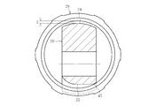
- FIG. 12 is a side view showing an assembled state of the inner joint member in the cage of the fixed type constant velocity universal joint shown in FIG. 11.
- FIG. 6 is a side view of the cage of FIG. 5, showing a cage of a fixed type constant velocity universal joint. It is a side view which shows the 1st modification of a cage. It is a side view which shows the 2nd modification of a cage. It is a side view which shows the 3rd modification of a cage. It is a side view which shows the 4th modification of a cage. It is a side view which shows the 5th modification of a cage.
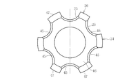
- FIG. 20 is a front view of the inner joint member shown in FIG. 19.
- FIG. 20 is a cross-sectional view of the inner joint member shown in FIG. 19.
- FIG. 20 is a cross-sectional view showing a method of incorporating the cage into the cage using the inner joint member shown in FIG. 19. It is explanatory drawing of the clearance gap formed at the time of incorporating in a cage. It is a perspective view which shows the other modification of an inner side coupling member.
- FIG. 25 is a front view of the inner joint member shown in FIG. 24.
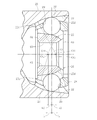
- the fixed type constant velocity universal joint includes an outer joint member 23 in which a plurality (six) of track grooves 22 are formed on the inner spherical surface 21 along the axial direction, and an outer spherical surface 24.
- An inner joint member 26 in which a plurality of (six) track grooves 25 paired with the track groove 22 of the outer joint member 23 are formed along the axial direction, and the track groove 22 and the inner joint member 26 of the outer joint member 23 are formed.
- a plurality of (six) balls 27 which are interposed between the track grooves 25 and transmit torque, and are interposed between the inner spherical surface 21 of the outer joint member 23 and the outer spherical surface 24 of the inner joint member 26.
- a cage 28 having a pocket (pocket) 29 for holding the. In this case, as shown in FIG. 2, six pockets 29 are arranged at an equal pitch (60 ° pitch) along the circumferential direction.
- the track groove 22 of the outer joint member 23 includes a back side track groove 22a in which the track groove bottom is an arc portion, and an opening side track groove 22b in which the track groove bottom is a straight portion parallel to the axis of the outer joint member.
- the back side track groove 22a is shifted from the joint center O in the axial direction to the opening side of the outer joint member 23 in the axial direction.
- the track groove 25 of the inner joint member 26 includes a back side track groove 25a in which the track groove bottom is a straight portion parallel to the inner joint member axis, and an opening side track groove 25b in which the track groove bottom is an arc portion. .
- the center of curvature O2 of the opening side track groove 25b is provided at an equal distance k away from the joint center O in the axial direction on the back side opposite to the center of curvature O1 of the back side track groove 22a of the outer joint member 23.
- a female serration (female spline) 61 that is a torque transmitting portion is formed on the inner diameter surface of the hole 60 of the inner joint member 26. That is, a shaft (not shown) is inserted into the hole 60 of the inner joint member 26, and the male serration provided on the shaft is engaged with the female serration 61 of the inner joint member 26. Thereby, the torque between the shaft and the inner joint member 26 is transmitted.
- the center of curvature O3 of the outer spherical surface 28a and the center of curvature O4 of the inner spherical surface 28b are offset in the axial direction by an equal distance k2 with respect to the joint center (cage center) O.
- the amount is made substantially the same as the offset amount of the track groove.
- the outer spherical surface 28a of the cage 28 can form a substantially concentric arc (a concentric arc having different curvature radii) with the groove bottom of the inner track groove 22a of the outer joint member 23.
- the depth can be prevented from becoming shallow, and the thickness (diameter thickness) on the opening side of the cage 28 can be increased.
- the cage wall thickness at the pocket center position of the cage 28 is t CAGE
- the pitch circle radius of the ball 27 when the operating angle is 0 ° is PCR BALL
- this ratio t CAGE / PCR BALL is set to 0.20 or more and 0.23 or less.
- the ratio r1 between the pitch circle diameter PCD BALL of the ball 27 and the diameter D BALL of the ball 27 is set to 3.0 or more and 3.3 or less. That is, 3.0 ⁇ r1 ⁇ 3.3.
- the ratio r2 between the outer diameter D OUTER of the outer joint member 23 and the diameter PCD BALL of the ball 27 is set to 4.6 or more and 4.8 or less. That is, 4.6 ⁇ r2 ⁇ 4.8.
- the pitch circle radius PCR BALL is the radius of the locus of the circle drawn by the ball center
- the center of curvature O1 of the track groove 22 of the outer joint member 23 is disposed closer to the center of the joint than the center of curvature O3 of the outer spherical surface 28a of the cage 28, and the center of curvature of the track groove 25 of the inner joint member 26 is.
- O2 is disposed on the anti-joint center side of the center of curvature O4 of the inner spherical surface 28b of the cage 28.
- the track offset angle ( ⁇ TRACK ) is set slightly larger than the cage offset angle ( ⁇ CAGE ).
- the inner joint member serration PCD dimension is a dimension that is fixed depending on the size, the inner joint member serration PCD dimension can be used to represent the degree of reduction in the outer diameter of the outer joint member 23. That is, the fact that the ratio r5 between the outer diameter of the outer joint member 23 and the inner joint member serration PCD dimension is small means that the outer diameter of the outer joint member 23 is small. For this reason, by setting in this way, this fixed type constant velocity universal joint contributes to downsizing.
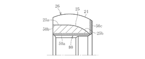
- the inner joint member 26 is provided with an uncured portion 80 (range indicated by cross-hatching) as shown in FIGS. 7A to 7D.
- the uncured portion 80 is formed only on the inner diameter portion 50a
- the uncured portion 80 is formed on the inner diameter portion 50a, the joint back side end surface 50b, and the joint opening side end surface 50c.
- the uncured portion 80 is formed on the inner diameter portion 50a and the joint back side end surface 50b.
- FIG. 7D the uncured portion 80 is formed on the inner diameter portion 50a and the joint opening side end surface 50c.
- the uncured portion 80 is an uncured portion, an uncarburized portion, or a low-cured portion (tempered portion).
- the carbon content is 0.5% or more and the surface hardness (uncured portion 80) is HV130 to HV650.
- the surface hardness of the joint back side end surface 50b (50C) which is the uncured portion 80 is HV250 to HV650, and the surface hardness of the joint back side end surface 50b (50C) which is not the uncured portion 80 is HV650 or more.
- the thermosetting treatment unit 50 may be carburizing, quenching, and tempering, or the surface hardening may be induction hardening, tempering.
- the induction hardening and tempering process is a process of making a hardened hardened layer on the surface layer by rapidly heating the surface of the object to be heated to the quenching temperature using high frequency induction heating and further rapidly cooling the surface. Abrasion resistance can be improved and mechanical properties can be enhanced.
- the carburizing and quenching process is a process in which carbon is infiltrated / diffused from the surface of the low carbon material and then quenched.
- the vicinity of the surface with a high carbon concentration is hard and has a compressive residual stress, and the inside with a low carbon concentration becomes low carbon martensite with high toughness. As a result, it is possible to provide a tough and wear-resistant characteristic. By performing such a quenching process, it is possible to improve the durability of the outer joint member to be formed.
- the inner joint member 26 is also subjected to a hardening process on the outer spherical surface 24 and the track groove bottom.
- the surface hardness of the outer spherical surface 24 and the track groove bottom is set to HV650 or more.
- the surface hardening process may be an induction hardening tempering process.
- the core hardness of the inner joint member 26 is set to HV130 or more.
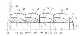
- a plurality (four in the illustrated example) of the inner joint members 26 are arranged along the axial direction.
- a thermosetting process for example, carburizing, quenching, and tempering process, is performed in a state of being disposed (in a state of being overlapped in a so-called dumpling shape). That is, the jig J provided with the shaft member 52 and the stopper member 53 is used.
- Each inner joint member 26 is externally fitted to a shaft member 52 protruding from the reference surface 51, and a stopper member 53 is mounted on the end surface of the shaft member on the side opposite to the reference surface.
- the plurality of inner joint members 26 are sandwiched between the reference surface 51 and the stopper member 53.
- the inner joint member 26 on the reference surface 51 side has an end surface 50b on the joint back side in contact with the reference surface 51, and each inner joint member 26 has an end surface 50b on the joint back side facing the joint surface and a joint opening side.
- the end surface 50c contacts.
- the end surface 50 c on the joint opening side of the inner joint member 26 on the stopper member 53 side contacts the stopper member 53.
- positioned along the circumferential direction is formed in the internal diameter part of each end surface 50b of the inner side coupling member 26.
- the protrusion amount W of the convex portion 55 is, for example, about 0.2 mm.
- the stopper member 53 of the jig J in this case is provided with a circumferential cutout 57 on the outer peripheral side of the end surface 56 a on the reference surface side of the pressing plate 56.
- the depth dimension W1 of the circumferential cutout 57 is, for example, about 0.2 mm.
- a gap 58 is formed between the end surfaces 50b and 50c facing each other.
- a gap 58 is formed between the end surface 50 b of the inner joint member 26 on the reference surface side and the reference surface 51, and between the end surface 50 c of the inner joint member 26 on the stopper member side and the pressing plate 56 of the stopper member 53.
- a gap 58 is formed in the gap.
- each end face 50b, 50c can be subjected to a surface hardening treatment (carburizing quenching and tempering), and a hardened portion 85 having a surface hardness of HV650 or more can be formed.
- a surface hardening treatment carburizing quenching and tempering
- a hardened portion 85 having a surface hardness of HV650 or more can be formed.
- the number of balls is six, a relatively large ball can be used. For this reason, an allowable torque capacity of one ball can be secured, and the ball can be arranged in a small PCD, that is, the outer diameter can be made compact. Since the thickness of the column portion between the pockets of the cage 28 can also be increased, the strength at a high operating angle can be ensured.
- the ratio of the pitch circle diameter PCD BALL of the ball 27 to the diameter of the ball 27 is 3.0 or more and 3.3 or less, the strength and durability as a constant velocity universal joint can be secured, A highly accurate constant velocity universal joint can be provided.
- the ratio between the pitch circle diameter PCD BALL and the diameter of the ball 27 is r1, if r1 ⁇ 3.0, if the ball 27 has a large diameter, the inner joint member 26 is too thin.
- the pitch diameter of the ball 27 is small, the surface pressure between the inner joint member / outer joint member 26, 23 and the ball increases, and there is a concern about durability.
- the ratio of the outer diameter of the outer joint member 23 to the diameter of the ball 27 is 4.6 or more and 4.8 or less. Thereby, further strength and durability can be secured.
- the ratio r2 between the outer diameter of the outer joint member 23 and the diameter of the ball 27 is r2
- r2 ⁇ 4.6 the thickness of the outer joint member 23 becomes too thin when the diameter of the ball 27 is large.
- the outer diameter of the outer joint member 23 is small, the surface pressure between the inner joint member / outer joint member 26, 23 and the ball 27 increases, and there is a concern about durability.
- r2> 4.8 the load capacity of the ball is reduced when the diameter of the ball 27 is small, and there is a concern in terms of durability, and the outer joint member 23 is compact when the outer diameter is large. Cannot be achieved.
- the thickness of the end portion on the joint opening side of the cage 28 can be formed thicker than other portions. Even if the cage 28 is thinly formed in order to reduce the size and weight of the joint, the joint opening side end of the cage 28 has a strength that can withstand the load applied when the joint is rotated at a high operating angle. Can do.
- the angles (offset angles) ⁇ 3 and ⁇ 4 of the cage 28 are set to 2.7 ° or more and 5.7 ° or less, the thickness of the end portion on the joint opening side of the cage 28 is thicker than other portions. Molded.
- the offset angles ⁇ 3 and ⁇ 4 of the cage 28 are less than 2.7 °, the end portion on the joint opening side of the cage 28 becomes thin, and sufficient strength cannot be ensured. If the angle exceeds 5.7 °, the thickness of the end of the cage 28 on the back side of the joint becomes extremely thin. Heat treatment is generally performed in the cage manufacturing process. However, when the thickness of the cage 28 becomes extremely thin, an uncured layer due to the heat treatment is reduced in the thin portion, and the toughness is lowered and sufficient strength can be secured. Disappear. Further, if the thickness difference between the end portion on the joint opening side of the cage 28 and the end portion on the back side of the joint is large, the workability may be deteriorated.
- the surface hardness of the inner diameter portion 50a is set to HV130 to HV650, and the surface hardness of the track groove bottom and the outer spherical surface is set to HV650 or more, thereby improving the strength of the inner joint member 26 while ensuring the durability of the track groove bottom and the outer spherical surface.
- the carbon content of steel increases, the grain boundary cementite increases and the grain boundary strength decreases during heat treatment. Further, since the hardness of the hardened layer increases and the intergranular crack easily propagates, the strength is lowered. Therefore, when the carbon content of the inner diameter portion 50a is 0.5% or more after the heat treatment, the inner joint member By reducing the inner diameter hardness of the inner joint member 26, the strength of the inner joint member 26 can be improved.
- the fixed type constant velocity universal joint of the present invention can achieve downsizing and can secure the strength of the inner joint member even if the downsizing is achieved. For this reason, it is possible to apply a shaft having the same specifications as the conventional one, and it is possible to share the existing shaft with a conventional product, thereby achieving cost reduction.
- the offset amount k of the cage 28 is made substantially the same as the offset amount k2 of the track grooves 22 and 25. For this reason, it is possible to prevent the depth of the track groove on the back side of the joint from becoming shallow, and to increase the thickness (diameter thickness) of the cage 28 on the opening side. For this reason, it is possible to prevent the ball 27 at a high angle from riding on the track edge, and an excessive stress does not act on the edge. That is, it is possible to prevent a decrease in torsional torque load capacity at high angles, to improve (improve) high angle endurance life, and to increase the strength of breakage caused by plastic deformation of the track grooves 25 and 22 of the inner joint member 26 and the outer joint member 23 at high angles. Improvement (improvement) can be achieved.
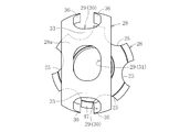
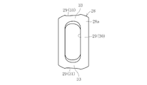
- FIG. 11 shows another embodiment, and the cage 28 in this case has four pairs of a pair of long pockets 30 having a large circumferential interval and a pair of short pockets 31 having a small circumferential interval. . Then, the pair of long pockets 30 are shifted 180 degrees along the circumferential direction, and the pair of short pockets 31 are shifted 180 degrees along the circumferential direction so that the long pockets 30 and the short pockets 31 are alternately positioned along the circumferential direction. Is arranged. For this reason, there are four column portions (cage column portions) 33 provided between the pockets.
- the long pocket 30 accommodates two balls 27 and the short pocket 31 accommodates one ball 27.
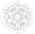
- the pitch angle e on the PCD of the two balls 27 accommodated in the long pocket 30 is made smaller than 60 degrees, and the pitch angle d of the other balls 27 is made larger than 60 degrees.
- the shoulder width dimension f between the two track grooves of the outer joint member 23 corresponding to the long pocket 30 of the cage 28 is set smaller than the pocket width g in the cage axial direction. That is, the track grooves 25 and 22 of the inner joint member 26 and the outer joint member 23 are arranged at unequal pitches in the circumferential direction, and a plurality of inner spherical surfaces arranged between the track grooves of the outer joint member 23 are arranged.
- the circumferential length (shoulder width dimension between track grooves) f of the opening side end portion of the inner spherical surface disposed within the minimum pitch is set to be smaller than the pocket width g of the cage 28. Furthermore, as shown in FIG. 13, the axial length i of the inner joint member 26 is shorter than the circumferential interval h of the long pocket 30.
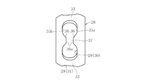
- the long pocket 30 has a bulging portion 36 projecting inwardly of the long pocket at the center in the longitudinal direction of the long sides 35 a and 35 b facing the long pocket 30.
- 36 is provided to form two ball accommodating portions 38, 38 connected to the long pocket 30 through the slit 37.
- the bulging portions 36, 36 are continuous spherical surfaces having the same curvature radius as the outer spherical surface 28 a of the cage 28, and the inner surfaces are continuous spherical surfaces having the same curvature radius as the inner spherical surface 28 b of the cage 28.
- the bulging portion 36 has a trapezoidal shape in which the side is an arcuate surface when viewed from the cage outer peripheral side. For this reason, the projecting end surface 36a of each bulging portion 36 is a plane extending along the circumferential direction of the cage, and is opposed (facing) with a predetermined interval M.
- the predetermined interval M is a dimension that does not interfere with the shoulder 47 (protrusion between adjacent track grooves) of the inner joint member 26 during assembly.
- the size and shape of the bulging portion 36 must be such that the movement of the ball 27 accommodated in the ball accommodating portion 38 is not hindered when rotating with an operating angle.
- the bulging portion 36 can be formed by machining or plastic working when the long pocket 30 is formed.
- the pair of long pockets 30 having a large circumferential interval and the pair of short pockets 31 having a small circumferential interval, and the pair of long pockets 30 are shifted by 180 degrees along the circumferential direction.
- the pair of short pockets 31 are shifted 180 degrees along the circumferential direction, and the long pockets 30 and the short pockets 31 are alternately arranged along the circumferential direction.
- the number can be four, and the circumferential length of one pillar 33 can be increased.
- each cage post 33 can be increased, so that a large ball 27 can be arranged on a small PCD, and the fixed constant velocity universal joint can be made compact without reducing the load capacity.
- the cage 28 can be reduced in size, and the cage 28 can be prevented from being damaged by a torsional torque load at a high angle.
- the inner joint member 26 can be easily assembled into the cage 28. That is, when the inner joint member 26 is incorporated into the cage 28, as shown in FIGS. 13 and 14, one shoulder 47 of the inner joint member 26 is dropped into one long pocket 30. By using the long pocket 30 for the pocket 29 into which the water is dropped, the workability can be improved.
- the rigidity of the frame (window frame) for constituting the long pocket 30 can be improved.
- deformation of the cage 28 due to insufficient rigidity of the window frame can be prevented, and the operability of the joint can be maintained, and stable operability can be exhibited over a long period of time.
- an inlay edge portion of the opening (inlet) of the outer joint member 23 and a pocket edge portion on the cage outer spherical surface 28a side are provided.
- Interference can be delayed or eliminated, and by the bulging portion 36 of the long side 35b on the joint back side, the back edge portion of the outer spherical surface 24 of the inner joint member 26 and the pocket edge portion on the cage inner spherical surface 28b side Interference can be delayed or eliminated.
- the track grooves 25 and 22 of the inner joint member 26 and the outer joint member 23 are arranged at unequal pitches in the circumferential direction, and the outer joint member 23.
- the circumferential length f of the opening side end portion of the inner spherical surface disposed within the minimum pitch is determined from the width g of the pocket 29 of the cage 28. It is set small.
- the pockets 29 of the cage 28 are incorporated so as to face the inner spherical surface disposed within the minimum pitch of the outer joint member 23.
- the inner spherical surface is the outer periphery of the cage 28. The cage 28 can be easily incorporated into the outer joint member 23 without interfering with the surface.
- the phases of two pitches positioned symmetrically with respect to the joint center are set smaller than 60 °, and the remaining four pitches
- the circumferential length f of the opening side end portion of the inner spherical surface of the outer joint member 23 disposed within the pitch of the phase smaller than 60 ° is set to the pocket 29 of the cage 28. It is set to be smaller than the width of.
- the cage 28 can be easily incorporated into the outer joint member 23. Further, since the inner spherical surface (opening side end portion) having a circumferential length smaller than the width of the pocket 29 is arranged symmetrically with respect to the joint center, it becomes easier to incorporate.
- the bulging portions 36 and 36 have a so-called trapezoidal shape, but may have shapes as shown in FIGS. 15B, 15C, and 15D. That is, the bulging portions 36 and 36 in FIG. 15B have rounded corners on the protruding end surface 36a of the bulging portion 36, and the bulging portions 36 and 36 in FIG. 15C have trapezoidal shapes in which the base corner portion is not gentle. And the bulging parts 36 and 36 of FIG. 15D are made into the rectangular shape.
- either one of the pair of bulging portions 36, 36 may be omitted.
- the bulging part 36 is provided only on the long side 35a side on the joint opening side
- the bulging part 36 is provided only on the long side 35b side on the joint opening side.
- interference between the inlay edge portion of the opening (inlet) of the outer joint member 23 and the pocket edge portion on the cage outer spherical surface 28a side can be delayed or eliminated, as shown in FIG. 16B. Then, the interference between the back edge portion of the outer spherical surface 24 of the inner joint member 26 and the pocket edge portion on the cage inner spherical surface 28b side can be delayed or eliminated.
- a long circular hole in which the bulging portion 36 is not provided in the long pocket 30 may be used.
- the pillar portion between the pockets adjacent in the circumferential direction may be removed. That is, the pair of pillars in the opposite direction with respect to the cage center may be removed.
- this removal method it can carry out by press work, milling, etc., for example.
- a part of the pillar portion to be removed remains, but in the cage 28 shown in FIGS. 17 and 18, the whole (all) of the pillar portion to be removed is removed. Yes.
- the pillar portion disposed in the large pitch may be removed.
- the pillar portion disposed in the small pitch is not provided. It is desirable to remove and leave the thick pillars arranged in the large pitch.
- the cage 28 can be easily formed by removing the pillar portion in the existing cage, and the removal of the pillar portion can be performed by milling even if it is press working. It may be, and can be stably formed by these various plastic workings.
- the long pocket 30 capable of holding the two torque transmitting balls 27 is formed in the cage 28 and the circumferential length h of the long pocket 30 is set larger than the width i of the inner joint member 26, It is possible to improve the assemblability when the inner joint member 26 is assembled into the cage 28.
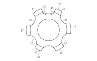
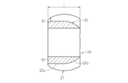
- a notch 45 may be provided at the back end of one track groove 25 (25A) of the inner joint member 26 (terminal edge on the joint back side).
- the notch 45 in this case is configured by a tapered surface formed at a corner portion between the back side end and the inner joint member end surface 46.
- this notch part 45 is comprised from the inclination part. In this case, it may be molding by machining or molding by plastic working.
- the track groove 25A in which the notch 45 is formed is fitted to the side frame portion 48 on the thinner side than the pocket 30, and the protrusion 47A on the counterclockwise side from the track groove 25A is connected to the pocket 30 of the cage 28.
- the inner joint member 26 is rotated in the direction of the arrow X around the bottom of the notch 45.
- the rotation radius C can be made smaller than the rotation radius B without the notch 45 (the rotation radius of the conventional product).
- the rotation radius C is a dimension between the bottom center portion of the notch portion 45 and one opening edge 49 of the track groove 25B opposite to the track groove 25A by 180 degrees.
- the inner joint member 26 After the inner joint member 26 is fitted into the cage 28, the inner joint member 26 is rotated by 90 ° with respect to the cage 28, and the axis of the inner joint member 26 is aligned with the axis of the cage 28 and placed in a normal posture. To do. As a result, the inner joint member 26 can be incorporated into the cage 28.
- the inner joint member 26 can be rotated with the notch 45 as a starting point when assembled in the cage 28, and the radius of rotation of the inner joint member 26 is increased. Can be reduced. Therefore, a larger space can be secured between the inner diameter of the cage 28 and the inner joint member 26, and accordingly, the inner diameter A of the cage 28 can be set smaller. That is, in the state where the track groove 25 of the inner joint member 26 in which the notch 45 is formed is straddled over the inlet of the cage 28, the notch 45 approaches the inlet (inlay) as shown in FIG. Or touching.
- the inner joint member 26 having the notch 45 can be further lowered and inserted as compared with the conventional inner joint member not having the notch 45. Thereby, since the clearance gap S between the upper end surface of the inner joint member 26 and an inlet part can be ensured large, an assembly
- the cross-sectional area on the inlay side of the cage 28 can be increased, the rigidity of the thin side frame portion 48 of the cage 28 can be improved, and a spherical contact area can be ensured.
- An increase in surface pressure can be prevented, heat generation and a decrease in durability can be avoided, and further, deformation of the cage 28 and a decrease in strength can also be avoided. That is, the rigidity of the cage 28 can be improved without reducing the load capacity or the spherical surface area of the inner joint member 26.
- the area of the inner spherical surface 28b of the cage 28 can be enlarged, the contact area of the inner joint member 26 with the outer spherical surface 24 can be enlarged, and there is an advantage that the durability is stabilized in addition to the improvement in rigidity.
- the size of the notch 45 can be changed within a range in which the radius of rotation of the inner joint member 26 when the inner joint member 26 is assembled into the cage 28 can be reduced, but if it is too large, the inner joint member 26 will have insufficient strength. Or the ball rolling range of the track groove 25 becomes small, and if it is too small, the turning radius cannot be made too small.
- FIGS. 24 to 26 a notch 45 is formed at the end on the back side of all the track grooves 25.
- FIG. 24 to 26 a notch 45 is formed at the end on the back side of all the track grooves 25.
- the inner joint member 26 can be rotated from the notch 45 as a starting point when assembled, similarly to the inner joint member 26 shown in FIGS. 19 to 21.
- the turning radius of the inner joint member 26 can be reduced. Therefore, the inner joint member 26 shown in FIGS. 24 to 26 has the same effect as the inner joint member 26 shown in FIGS. 19 to 21.
- FIG. 27A has a concave round shape
- the cutout 45 shown in FIG. 27B has a convex round shape.
- the inner joint member 26 can be rotated from the cutout 45 as a starting point, and the rotation radius of the inner joint member 26 can be reduced. Can do. Further, as shown in FIGS. 28A and 28B, the notch 45 may be formed at a part of the track groove end (the bottom in the example).
- the notch 45 may be configured by a stepped portion or the like other than the one shown in FIGS. 19 to 21, the one shown in FIGS. 27A and 27B, or the one shown in FIGS. 28A and 28B. . Even the cutout 45 such as the stepped portion exhibits the function as the cutout 45.
- FIG. 29 shows another embodiment, in which the track groove bottoms of the inner joint member 26 and the outer joint member 23 are provided with an arc portion and a tapered portion.
- the track groove bottom 22c includes an inner side track groove 22c having a circular arc portion as a track groove bottom, and an opening side track groove 22d in which the track groove bottom is inclined from the back side toward the opening side toward the outer diameter side.
- the back side track groove 22c has its center of curvature O1 shifted from the joint center O in the axial direction toward the opening side of the outer joint member 23.
- the track groove 25 of the inner joint member 26 includes a back-side track groove 25c in which the track groove bottom is inclined from the opening side toward the back side toward the outer diameter side, and an opening-side track groove 25d in which the track groove bottom is an arc portion. It consists of.
- the center of curvature O2 of the opening side track groove 25b is provided at an equal distance k away from the joint center O in the axial direction on the back side opposite to the center of curvature O1 of the back side track groove 22a of the outer joint member 23.
- the center of curvature O3 of the outer spherical surface 28a of the cage 28 and the center of curvature O4 of the inner spherical surface 28b of the cage 28 are offset in the axial direction by an equal distance with respect to the joint center O.
- the offset amount k is substantially the same as the offset amount k2 of the track grooves 22 and 25.
- the carbon content of the inner diameter portion 50a is set to 0.5% or more, the surface hardness of the inner diameter portion 50a is set to HV130 to HV650, and the surface hardness of the track groove bottom and the outer spherical surface is set to HV650 or more. Etc.
- the fixed type constant velocity universal joint shown in FIG. 29 has the same effects as the fixed type constant velocity universal joint shown in FIG. In FIG. 1, by adopting an undercut free type in which the track groove bottoms of the inner joint member 26 and the outer joint member 23 are provided with an arc portion and a straight portion, the joint operating angle can be increased. On the other hand, if the track groove bottom has an arc portion and a tapered portion as in the fixed type constant velocity universal joint shown in FIG. 33, the angle can be further increased.
- the track groove is an undercut free type having an arc portion and a straight portion, but as shown in FIG. It may be a mold (BJ).
- An outer joint member 73 in which a plurality of track grooves 72 are formed in the BJ type inner spherical surface 71 along the axial direction at equal intervals in the circumferential direction, and a plurality of pairs that form a pair with the track grooves 72 of the outer joint member 73 on the outer spherical surface 74.
- a cage 78 that is interposed between the inner spherical surface 71 of the outer joint member 73 and the outer spherical surface 74 of the inner joint member 76 and holds the ball 77.
- the cage 78 is provided with a plurality of pockets 79 for accommodating the balls 77 along the circumferential direction.
- the cage 78 is in spherical contact with the inner spherical surface of the outer joint member 73 and the outer spherical surface of the inner joint member 76, respectively.
- the centers of curvature (O1, O2) of the ball center locus lines of the track grooves 72, 75 are at positions symmetrical to the joint center O, respectively.
- the center of curvature O1 and the center of curvature O2 are offset from the joint center O by an equal distance in the opposite direction and offset in the axial direction.
- the track formed by the track groove 72 of the outer joint member 73 and the track groove 75 of the inner joint member 76 has a wedge shape that gradually expands from one to the other in the axial direction.
- Each ball 77 is accommodated in this wedge-shaped track, and transmits torque between the outer joint member 73 and the inner joint member 76.
- a cage 78 is incorporated to hold all the balls 77 in the joint plane (plane perpendicular to the bisector of the operating angle).
- the range of 0 ⁇ r1 ⁇ 3.3 is set, or in the inner joint member 76 after heat treatment, the carbon content of the inner diameter portion is 0.5% or more, the surface hardness of the inner diameter portion is HV130 to HV650, and the track groove The surface hardness of the bottom and outer spherical surface is set to HV650 or more.
- the curvature center O1 and the curvature center O3 are slightly different.
- the center of curvature O2 and the center of curvature O4 are disposed at positions slightly deviated from each other, the center of curvature O2 is provided even if the center of curvature O1 and the center of curvature O3 are the same position.
- the center of curvature O4 may be at the same position.
- the shift amount can be arbitrarily set, but the offset amount k and the shift amount (k ⁇ k2). Is preferably set to (k ⁇ k2) /k ⁇ 0.3.
- (k ⁇ k2) / k> 0.3 there is no difference from the conventional fixed type constant velocity universal joint shown in FIG. 31, the track groove depth on the inner side of the joint becomes shallower, and the cage 28 on the opening side becomes smaller. It becomes impossible to increase the wall thickness of the joint, which is less than the required strength of the joint.
- the circumferential interval h of the long pockets 30 can be variously set within the range in which the cage 28 can be easily incorporated into the inner joint member 26 and the rigidity of the column portion 33 is not lowered.
- the track groove shoulder width dimension f, the pocket width g of the cage 28 in the cage axial direction, and the like can also be set in consideration of the ease of incorporation of the cage 28 into the outer joint member 23 and the like.
- the protruding end surface 36a of the bulging portion 36 may be a curved surface without being a flat surface.
- the cages 28 and 78 having the long pockets 30 as shown in FIGS. 15 to 18 may be used. Moreover, you may use the inner side coupling member 26 which has the notch part 45 as shown to FIG. 19 and FIG.
- the balls 27 are arranged at unequal pitches in the circumferential direction. Will be disposed.
- two balls arranged at less than 60 ° are accommodated in one long pocket 30. That is, it has a shape in which a column portion between two balls disposed at less than 60 ° is omitted.
- this pillar part may not be omitted. In this case, as shown in FIG. 1, six pillar parts are formed, and the strength of the entire cage is improved. Increases rigidity.
- the track groove may be an undercut free type having an arc portion and a straight portion, or the track groove may be a bar field type having only the arc portion.
Landscapes
- Engineering & Computer Science (AREA)
- General Engineering & Computer Science (AREA)
- Mechanical Engineering (AREA)
- Rolling Contact Bearings (AREA)
- Heat Treatment Of Articles (AREA)
Abstract
内側継手部材やケージの強度を確保しつつ、小型軽量化を図り得ることが可能であり、また高角度強度および耐久性を向上させることができる固定式等速自在継手を提供する。 トルク伝達ボールのピッチ円直径(PCDBALL)と前記トルク伝達ボールの直径(DBALL)との比r1(=PCDBALL/DBALL)を、3.0≦r1≦3.3の範囲に設定する。熱処理後の内側継手部材において、内径部の炭素含有量を0.5%以上とし、内径部の表面硬度をHV130~HV650とし、トラック溝底及び外球面の表面硬度をHV650以上とした。
Description
本発明は、本発明は、自動車や各種産業機械の動力伝達系において使用され、駆動側と従動側の二軸間で作動角変位を許容しながら回転トルクを伝達する固定式等速自在継手に関する。
自動車及びこれに準ずる各種車両においては、エンジンからの駆動力をホイールに伝達する動力伝達経路に、二軸間で角度変位や軸方向変位があった場合でも等速で回転動力を伝達することが可能な等速自在継手を配設することが行われている。等速自在継手には、プランジング運動(軸方向変位)を行わない固定式等速自在継手とプランジング運動を行う摺動式等速自在継手がある。固定式等速自在継手としては、バーフィールド型(BJ)やアンダーカットフリー型(UJ)が広く知られている。
例えば、UJタイプの固定式等速自在継手は、図31と図32に示すように内球面1に複数のトラック溝2が円周方向等間隔に軸方向に沿って形成された外側継手部材3と、外球面4に外側継手部材3のトラック溝2と対をなす複数のトラック溝5が円周方向等間隔に軸方向に沿って形成された内側継手部材6と、外側継手部材3のトラック溝2と内側継手部材6のトラック溝5との間に介在してトルクを伝達する複数のボール7と、外側継手部材3の内球面1と内側継手部材6の外球面4との間に介在してボール7を保持するケージ8とを備えている。ケージ8には、ボール7が収容されるポケット9が周方向に沿って複数配設されている。
また、外側継手部材3のトラック溝2は、奥側が円弧部2aとされ、開口側が直線部2bとされる。内側継手部材6のトラック溝5は、奥側が直線部5aとされ、開口側が円弧部5bとされる。内側継手部材6のトラック溝5の曲率中心O1および外側継手部材3のトラック溝2の曲率中心O2は、継手中心Oに対して等距離Fだけ軸方向に逆向きにオフセットされている。
近年においては、コンパクト化を図るために、図32に示すようにボールを8個としたものがある。この場合、ケージのポケット中心位置におけるケージ肉厚をtCAGEとするとともに、作動角が0°のときのボールのピッチ円半径をPCRBALLとし、この比であるtCAGE/PCRBALLを0.11~0.19程度とされる。
また、従来のUJ型等速自在継手には、図33に示すように、小型軽量化のために、各トラック溝2,5の曲率中心O1,O2とトルク伝達ボール7の中心Qを結ぶ直線と、トルク伝達ボール7の中心Qと継手中心Oを結ぶ直線とが成すトラック溝のオフセット角θTRACKを、4°≦θTRACK≦6°の範囲に設定するものがある。
このようなものでは、外側継手部材3の内球面1の曲率中心O10(ケージ8の外球面8aの曲率中心)及び内側継手部材6の外球面4の曲率中心O20(ケージ8の内球面8bの曲率中心)も、それぞれ継手中心Oを挟んで軸方向に等距離だけオフセットされている。そして、ケージ8の内外球面8a,8bの曲率中心O10,O20とトルク伝達ボール7の中心Qを結ぶ直線と、トルク伝達ボール7の中心Qと継手中心Oを結ぶ直線とが成すケージ8のオフセット角θCAGEを、0°<θCAGE<1°の範囲に設定している。このように、ケージ8は、そのオフセット角θCAGEが非常に小さく設定されているため、略均一な厚さに成形される。
近年、固定式等速自在継手の更なる小型軽量化のため、ケージ8の厚さを更に薄くすることが試みられている。図32に示す等速自在継手において、tCAGE/PCRBALLを0.11~0.19に保ったまま、更なるコンパクト化、つまりピッチ円半径を小さくしようとすれば、ケージ8の肉厚が必然的に薄くなる。このように薄くなれば、ポケット9間の柱部、及びポケット9の側枠(軸方向に対面する窓枠)の剛性が低下する。すなわち、継手が高作動角をとった状態で回転する場合、ケージ8の継手開口側の端部に大きな負荷がかかるため、その部分の強度は確保しなければならない。しかしながら、高作動角時において、等速自在継手としての強度を確保することが困難である。
また、前記図32に示す継手の構成において、ケージ8の厚さを薄く設定すると、ケージ8が均一に薄く成形されるため、ケージ8の継手開口側の端部の強度を十分に確保することが困難であった。また、このケージ8の小型軽量化に伴う継手開口側の端部の強度低下は、特に小型車・軽自動車用等に適用する小サイズの固定式等速自在継手に顕著に認められる。
そこで、コンパクト化を図った新しいタイプの固定式等速自在継手として、特許文献1に記載のように、6個ボールタイプのものが提案されている。
特許文献1に記載のような構造とすることによって、等速自在継手のコンパクト化を実現できる。しかしながら、小さいピッチ円直径(PCD)に大きなボールを配置することになり、内部部品(内側継手部材、ボール、ケージ等からなる組立体)の強度バランスが今までの等速自在継手と異なることになる。
ところで、このようなものであっても、図34に示すように、内側継手部材6の内径面に雌セレーション10が形成され、この雌セレーション10に、シャフト11に形成された雄セレーション12が嵌合する。
このため、従来と同じシャフト11を適用した場合、雌セレーション10を形成したことによって、内側継手部材6の肉厚(特に、継手開口側)が薄くなる。このため、他部品である外側継手部材3やケージ8に比べて内側継手部材6の強度がバランス的に劣ることになる。すなわち、小さくピッチ円径(PCD)に大きなボールを配置し、従来と同じシャフトを使用すると、この継手開口側端13側の範囲H(図34における円で囲む範囲)での肉厚Tが小さくなる。このように肉厚Tが小さいと、範囲Hに発生する応力が大きくなる。なお、雄セレーション12の端部には周方向溝15が形成され、この周方向溝15に止め輪16が装着される。これによって、止め輪16が内側継手部材6の孔部内径面の端部(継手奥側端部)の切欠部17に係合して、シャフトの抜け止めが構成される。
そこで、本発明は斯かる実情に鑑み、内側継手部材やケージの強度を確保しつつ、小型軽量化を図り得ることが可能であり、また高角度強度および耐久性を向上させることができる固定式等速自在継手を提供しようとするものである。
本発明の第1の固定式等速自在継手は、内球面に軸方向に延びた複数のトラック溝を形成した外側継手部材と、外球面に軸方向に延びた複数のトラック溝を形成した内側継手部材と、前記外側継手部材のトラック溝と前記内側継手部材のトラック溝との対で形成されるボールトラックに1個ずつ配置した複数のトルク伝達ボールと、前記外側継手部材の内球面と前記内側継手部材の外球面との間に介在すると共に前記トルク伝達ボールを保持するケージを備えた固定式等速自在継手であって、前記トルク伝達ボールのピッチ円直径(PCDBALL)と前記トルク伝達ボールの直径(DBALL)との比r1(=PCDBALL/DBALL)を、3.0≦r1≦3.3の範囲に設定するとともに、熱処理後の内側継手部材において、内径部の炭素含有量を0.5%以上とし、内径部の表面硬度をHV(ビッカース硬さ)130~HV(ビッカース硬さ)650とし、トラック溝底及び外球面の表面硬度をHV(ビッカース硬さ)650以上としたものである。
本発明の第1の固定式等速自在継手によれば、内径部の表面硬度をHV130~HV650とし、トラック溝底及び外球面の表面硬度をHV650以上とすることによって、トラック溝底及び外球面の耐久性能を確保しながら内側継手部材の強度を向上させることができる。鋼は炭素量が多くなると、熱処理時に粒界セメンタイトが増加し、粒界強度が低下する。また、硬化層硬さが増加するために、粒界き裂が伝播しやすくなることで、強度低下が生じるため、熱処理後に内径部の炭素含有量を0.5%以上となる場合は、内側継手部材内径硬度を低下させることで内側継手部材強度を向上することができる。
3.0≦r1≦3.3の範囲に設定することによって、等速自在継手としての強度・耐久性を確保できる。
本発明の第2の固定式等速自在継手は、内球面に軸方向に延びた複数のトラック溝を形成した外側継手部材と、外球面に軸方向に延びた複数のトラック溝を形成した内側継手部材と、前記外側継手部材のトラック溝と前記内側継手部材のトラック溝との対で形成されるボールトラックに1個ずつ配置した複数のトルク伝達ボールと、前記外側継手部材の内球面と前記内側継手部材の外球面との間に介在すると共に前記トルク伝達ボールを保持するケージを備えた固定式等速自在継手であって、前記トルク伝達ボールのピッチ円直径(PCDBALL)と前記トルク伝達ボールの直径(DBALL)との比r1(=PCDBALL/DBALL)を、3.0≦r1≦3.3の範囲に設定するとともに、熱処理後の内側継手部材において、内径部の炭素含有量を0.5%未満とし、内径部の表面硬度をHV130以上とし、トラック溝底及び外球面の表面硬度をHV650以上としたものである。
本発明の第2の固定式等速自在継手によれば、内径部の表面硬度をHV130以上とし、トラック溝底及び外球面の表面硬度をHV650以上とすることによって、トラック溝底及び外球面の耐久性能を確保しながら内側継手部材の強度を向上させることができる。熱処理後に内径部の炭素含有量0.5%未満となる場合は、上記のような強度低下をまねかないため、HV130以上とすることで、内径継手部材強度を十分確保することができる。
内側継手部材の継手開口側の端面の表面硬度をHV650以上としたり、内側継手部材の継手奥側の端面の表面硬度をHV650以上としたりできる。また、前記内側継手部材の芯部硬度をHV130以上とし、内径部の表面硬度をHV250~HV650としたり、前記内側継手部材の芯部硬度をHV440~HV650とし、内径部の表面硬度をHV250~HV650としたりできる。
内側継手部材の継手奥側の端面に継手奥側に突出する凸部を設け、複数個の内側継手部材が、一の内側継手部材の継手奥側の端面の凸部が他の内側継手部材の開口側の端面に当接するように軸方向に沿って配設され、この状態で熱処理(浸炭焼入れ焼戻し処理)が施されてなるものである。
このように設定することによって、軸方向に沿って配設された内側継手部材の相対面する端面間に隙間が生じる。このため、これらの端面に熱処理(浸炭焼入れ焼戻し処理)を施すことができる。これに対して、軸方向に沿って配設された内側継手部材の相対面する端面間に隙間が無ければ、これらの端面に熱処理(浸炭焼入れ焼戻し処理)を施すことができない。
表面硬化処理が浸炭焼入焼戻し処理であっても、表面硬化処理が高周波焼入焼戻し処理であってもよい。高周波焼入れ焼戻し処理は、高周波誘導加熱を利用して被加熱物の表面を焼入れ温度まで急速加熱し、さらに急速冷却することにより表面層に焼入れ硬化層を作る処理である。耐摩耗性を向上させ、機械的性質を高めることができる。また、浸炭焼入処理とは、低炭素材料の表面から炭素を浸入/拡散させ、その後に焼入れを行う処理である。鋼の場合、炭素濃度の高い表面付近は硬くて圧縮の残留応力をもち、また炭素濃度の低い内部は、じん性の高い低炭素マルテンサイトとなる。これにより、強靭で耐摩耗の高い特性を与えることができる。このような焼入処理を行うことによって、形成される内側継手部材の耐久性の向上を図ることができる。
外側継手部材の外径(DOUTER)と前記トルク伝達ボールの直径(DBALL)との比r2(=DOUTER/DBALL)を、4.6≦r2≦4.8の範囲に設定することができる。外側継手部材の外径とボールの直径との比が4.6未満であると、ボールの直径が大きい場合は外側継手部材の肉厚が薄くなりすぎて、強度の点で懸念が生じ、外側継手部材の外径が小さい場合は内側継手部材・外側継手部材とボール間の面圧が大きくなり、耐久性の点で懸念が生じる。逆に、4.8を越えると、ボールの直径が小さい場合はボールの負荷容量が小さくなり、耐久性の点で懸念が生じ、外側継手部材の外径が大きい場合はコンパクト化が達成できない。
継手作動角が0°の状態における、前記ケージの内外球面の曲率中心と前記トルク伝達ボールの中心を結ぶ直線と、前記トルク伝達ボールの中心と継手中心とを結ぶ直線とが成すケージのオフセット角θCAGEを、2.7°≦θCAGE≦5.7°の範囲に設定することができる。
ケージのオフセット角θCAGEを、従来のケージのオフセット角(0°<θCAGE<1°)より大きく設定することによって、ケージの継手開口側の端部の肉厚が、他の部分に比べて厚く成形される。ケージのオフセット角が、2.7°未満であると、ケージの継手開口側の端部が薄くなり、十分な強度が確保できない。また、5.7°を越えると、ケージの継手奥側の端部の肉厚が極端に薄くなる。ケージの製造工程において一般的に熱処理を施すが、ケージの肉厚が極端に薄くなると、その肉厚の薄い部分では熱処理による未硬化層が少なくなり、靱性が低下し十分な強度が確保できなくなる。また、ケージの継手開口側の端部と継手奥側の端部とで、肉厚差が大きいと加工性の悪化も懸念される。
ケージのポケット中心位置におけるケージ肉厚をtCAGEとするとともに、作動角が0°のときのボールのピッチ円半径をPCRBALLとし、この比であるtCAGE/PCRBALLを0.20以上0.23以下とすることができる。tCAGE/PCRBALLが0.20未満となると、外径が大きくなり、コンパクト化が困難になったり、ケージの肉厚が薄くなったり、大角度時の必要継手強度が確保することが困難となる。一方、tCAGE/PCRBALLが0.23を越えると、内径セレーション部(シャフト嵌合部)における内側継手部材(内側継手部材)の肉厚が薄くなり、大角度時(高作動角時)の必要継手強度の確保が困難になったり、内側継手部材及び外側継手部材の球面が小さくなることにより、許容可能なトルクレベルが低下したりする。この結果、ボールが内側継手部材及び外側継手部材のトラック溝のエッジ部に乗り上げ易くなり、耐久性が著しく低下してしまうおそれがある。
外側継手部材のトラック溝の曲率中心と内側継手部材のトラック溝の曲率中心とを、継手中心に対して等距離だけ軸方向に逆向きにオフセットさせるとともに、ケージの外球面の曲率中心とケージの内球面の曲率中心とを、継手中心に対して等距離だけ軸方向に逆向きにオフセットさせ、このケージのオフセット量をトラック溝のオフセット量と略同一とすることができる。これによって、継手奥側のトラック溝深さが浅くなるのを防止できるとともに、開口側のケージの肉厚(径方向厚さ)を大きくすることができる。
ところで、内側継手部材をケージに組み込む際は、内側継手部材のトラック溝相互間に配設された外球面の一つを、ケージのポケットに挿入して、内側継手部材をケージ内に収納することになる。このため、内外継手部材の各トラック溝を、周方向不等ピッチに配設すると共に、狭いピッチ内に配設されたケージの柱部を除去したものとすれば、柱部を除去することによって、この除去部に内側継手部材の外球面を落とし込むことができる。
また、等速自在継手を組み立てる場合、外側継手部材にケージを組み込むことになる。このため、内外継手部材の各トラック溝相互間のピッチのうち、2つのピッチの位相を60°以下に設定すると共に、残りの4つのピッチの位相を60°以上に設定することによって、組み込み性の向上を図ることができる。すなわち、外側継手部材にケージを組み込む際は、ケージのポケットを、小さい位相のピッチ内に配設された外側継手部材の内球面に対向させて組み込むことになる。この際、小さいピッチ内に配設された内球面の開口側端部の周方向長さが、対向するケージのポケットの幅より小さく設定されることになり、前記内球面がケージの外周面に干渉することなく、ケージを外側継手部材に容易に組み込むことができる。
本発明の固定式等速自在継手は、小型化を達成でき、しかも小型化を図ったとしても、内側継手部材の強度を確保できる。このため、従来と同じ緒元のシャフトを適用することができ、従来の既存品との共用化を図ることができ、低コスト化を達成できる。
3.0≦r1≦3.3の範囲に設定することによって、等速自在継手としての強度・耐久性を確保することができ、高精度の等速自在継手を提供することができる。
また、外側継手部材の外径とボールの直径との比を、4.6以上4.8以下とすることによって、一層強度・耐久性を確保することができる。ケージのオフセット角度を、2.7°以上5.7°以下に設定することによって、ケージの継手開口側の端部の肉厚を、他の部分に比べて厚く成形することができ、継手の小型軽量化を図るためにケージを薄く成形しても、ケージの継手開口側の端部は、継手の高作動角回転時に付与される負荷に耐え得る強度を確保することができる。
0.20≦tCAGE/PCRBALL≦0.23とすることによって、小型化及びケージ強度の向上を図ることができ、しかも、ボールのトラック溝のエッジ部への乗り上げを防止できる。すなわち、本発明によれば、コンパクト化(小型化)を可能とするとともに、小型化してもケージの強度を確保でき、さらには、高角捩りトルク負荷時のケージ損傷を防止できて、高角強度の向上を図ることができる。このため、よりコンパクトなフォルムにて継手強度耐久性を従来品(8個ボールの固定式ジョイント)と同等以上に確保することができる。
ケージのオフセット量をトラック溝のオフセット量と略同一として大きくすることによって、継手奥側のトラック溝深さが浅くなるのを防止できるとともに、開口側のケージの肉厚(径方向厚さ)を大きくすることができる。このため、高角時のボールがトラックエッジに乗り上げるのを防止でき、エッジに過大な応力が作用することがなくなる。すなわち、高角時の捩りトルク負荷容量の低下を防ぎ、高角耐久寿命の向上(改善)や高角時の内側継手部材と外側継手部材のトラック溝の塑性変形に起因する破損強度の向上(改善)を図ることができる。
内側継手部材のトラック溝及び外側継手部材のトラック溝を円周方向に不等ピッチで配設し、狭いピッチのケージの柱を除去すれば、ケージの外側継手部材(外側継手部材)への組込みが容易となり、しかも、長窓が必然的に形成され、長窓幅が内側継手部材幅より大きくなって、内側継手部材のケージの組込みが容易となる。また、外側継手部材のトラック溝において、2つのピッチの位相を60°以下に設定すると共に、残りの4つのピッチの位相を60°以上に設定することによって、干渉なくケージの組込みができる。
以下本発明の実施の形態を図1~図30に基づいて説明する。
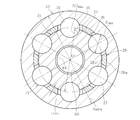
この固定式等速自在継手は、図1と図2に示すように内球面21に複数(6個)のトラック溝22が軸方向に沿って形成された外側継手部材23と、外球面24に外側継手部材23のトラック溝22と対をなす複数(6個)のトラック溝25が軸方向に沿って形成された内側継手部材26と、外側継手部材23のトラック溝22と内側継手部材26のトラック溝25との間に介在してトルクを伝達する複数(6個)のボール27と、外側継手部材23の内球面21と内側継手部材26の外球面24との間に介在してボール27を保持するポケット(ポケット)29を有するケージ28とを備えている。この場合、図2に示すように、ポケット29は円周方向に沿って等ピッチ(60°ピッチ)で6個配設されている。
前記外側継手部材23のトラック溝22は、トラック溝底が円弧部となる奥側トラック溝22aと、トラック溝底が外側継手部材軸線と平行なストレート部となる開口側トラック溝22bとからなる。奥側トラック溝22aは、その曲率中心O1を継手中心Oから軸方向に外側継手部材23の開口側にずらしている。また、内側継手部材26のトラック溝25は、トラック溝底が内側継手部材軸線と平行なストレート部となる奥側トラック溝25aと、トラック溝底が円弧部となる開口側トラック溝25bとからなる。開口側トラック溝25bの曲率中心O2を継手中心Oから軸方向に外側継手部材23の奥側トラック溝22aの曲率中心O1と反対側の奥側に等距離kだけ離して設けている。
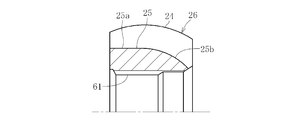
内側継手部材26の孔部60の内径面には、トルク伝達部位である雌セレーション(雌スプライン)61が形成されている。すなわち、内側継手部材26の孔部60にシャフト(図示省略)が嵌入され、このシャフトに設けられた雄セレーションが、内側継手部材26の雌セレーション61に嵌合する。これによって、シャフトと内側継手部材26間のトルクが伝達される。
ケージ28は、外球面28aの曲率中心O3と内球面28bの曲率中心O4とを、継手中心(ケージ中心)Oに対して等距離k2だけ軸方向に逆向きにオフセットさせ、このケージ28のオフセット量をトラック溝のオフセット量と略同一として大きくしている。
このため、ケージ28の外球面28aは、外側継手部材23の奥側トラック溝22aの溝底とほぼ同心円弧(曲率半径は相違する同心円弧)を形成することができ、継手奥側のトラック溝深さが浅くなるのを防止できるとともに、ケージ28の開口側の肉厚(径方向厚さ)を大きくすることができる。
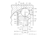
図3に示すように、ケージ28のポケット中心位置におけるケージ肉厚をtCAGEとするとともに、作動角が0°のときのボール27のピッチ円半径をPCRBALLとし、この比であるtCAGE/PCRBALLを0.20以上0.23以下とする。
また、図3に示すように、ボール27のピッチ円直径PCDBALLとボール27の直径DBALLとの比r1を、3.0以上3.3以下とする。すなわち、3.0≦r1≦3.3としている。外側継手部材23の外径DOUTERとボール27の直径PCDBALLとの比r2を、4.6以上4.8以下とする。すなわち、4.6≦r2≦4.8としている。
ここで、ピッチ円半径PCRBALLとは、ボール中心が描く円の軌跡の半径であり、ピッチ円直径PCDBALLとは、ボール中心が描く円の軌跡の直径である。すなわち、ピッチ円直径PCDBALLは、外側継手部材23のトラック溝22の曲率中心O1、又は、内側継手部材26のトラック溝25の曲率中心O2と、トルク伝達ボール7の中心Qとを結ぶ線分の長さPCRの2倍と定義する(PCDBALL=PCR×2)。
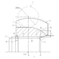
図4に示すように、作動角が0°のときにおいて、ケージ28の外球面28aの曲率中心O3とボール中心Qとを結んだ直線L3と、継手中心Oとボール中心Qとを結んだ直線Lとの成す角度θ3、及びケージ28の内球面28bの曲率中心O4とボール中心Qとを結んだ直線L4と、継手中心Oとボール中心Qとを結んだ直線Lとの成す角度θ4をそれぞれ2.7°以上5.7°以下に設定している。なお、角度θ3及びθ4は、ケージオフセット角(θCAGE)と呼ぶ。また、作動角が0°とは、外側継手部材23の軸線と内側継手部材の軸線とが一致する状態である。すなわち、2.7°≦θCAGE≦5.7°に設定される。
また、作動角が0°のときにおいて、外側継手部材23のトラック溝22の曲率中心O1とボール中心Qとを結んだ直線L1と、継手中心Oとボール中心Qとを結んだ直線Lとの成す角度θ1、及び内側継手部材26のトラック溝25の曲率中心O2とボール中心Qとを結んだ直線L2と、継手中心Oとボール中心Qとを結んだ直線Lとの成す角度θ2をそれぞれ前記オフセット角(θCAGE)と略同一に設定される。なお、角度θ1及び角度θ2は、トラックオフセット角(θTRACK)と呼ぶ。この実施形態では、外側継手部材23のトラック溝22の曲率中心O1をケージ28の外球面28aの曲率中心O3よりも反継手中心側に配置するとともに、内側継手部材26のトラック溝25の曲率中心O2を、ケージ28の内球面28bの曲率中心O4よりも反継手中心側に配置している。このため、この実施形態では、トラックオフセット角(θTRACK)がケージオフセット角(θCAGE)よりも僅かに大きく設定されている。
また、外側継手部材23の外径をDOUTREとし、内側継手部材セレーションPCD寸法をDOUTERとしたときに、3.0<r5(DOUTRE/DOUTER)<3.5とする。内側継手部材セレーションPCD寸法は、サイズによって固定される寸法であるため、外側継手部材23の外径の縮小度合いを表すために利用できる。つまり、外側継手部材23の外径と内側継手部材セレーションPCD寸法の比r5の値が小さいということは、外側継手部材23の外径が小さいことになる。このため、このように設定することによって、この固定式等速自在継手にコンパクト化に寄与する。
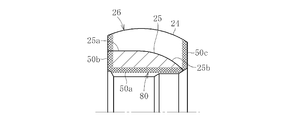
ところで、この内側継手部材26は、図7Aから図7Dに示すように、未硬化部80(クロスハッチングで示す範囲)が設けられる。図7Aでは、未硬化部80が内径部50aのみに形成され、図7Bでは、未硬化部80が内径部50aと継手奥側端面50bと継手開口側端面50cとに形成され、図7Cでは、未硬化部80が内径部50aと継手奥側端面50bとに形成され、図7Dでは、未硬化部80が内径部50aと継手開口側端面50cとに形成されている。ここで、未硬化部80とは、未硬化部、未浸炭、もしくは、低硬化部(テンパー部)である。
この際、内径部50aにおいては、熱処理後において、炭素含有量を0.5%以上であって、表面硬度(未硬化部80)をHV130~HV650としている。未硬化部80である継手奥側端面50b(50C)の表面硬度をHV250~HV650とし、未硬化部80でない継手奥側端面50b(50C)の表面硬度をHV650以上とする。
熱硬化処理部50は、浸炭焼入焼戻し処理であっても、表面硬化処理が高周波焼入焼戻し処理であってもよい。高周波焼入れ焼戻し処理は、高周波誘導加熱を利用して被加熱物の表面を焼入れ温度まで急速加熱し、さらに急速冷却することにより表面層に焼入れ硬化層を作る処理である。耐摩耗性を向上させ、機械的性質を高めることができる。また、浸炭焼入処理とは、低炭素材料の表面から炭素を浸入/拡散させ、その後に焼入れを行う処理である。鋼の場合、炭素濃度の高い表面付近は硬くて圧縮の残留応力をもち、また炭素濃度の低い内部は、じん性の高い低炭素マルテンサイトとなる。これにより、強靭で耐摩耗の高い特性を与えることができる。このような焼入処理を行うことによって、形成される外側継手部材の耐久性の向上を図ることができる。
また、内側継手部材26は、その外球面24及びトラック溝底に対しても硬化処理が施される。そして、外球面24及びトラック溝底の表面硬度をHV650以上としている。この硬化処理としても、浸炭焼入焼戻し処理であっても、表面硬化処理が高周波焼入焼戻し処理であってもよい。さらに、内側継手部材26の芯部硬度をHV130以上とする。
ところで、内径部を未浸炭とする場合(未硬化部80を形成する場合)に、図9に示すように、複数個(図例では4個)の内側継手部材26を軸心方向に沿って配設した状態(いわゆる団子状に重ね合わせた状態)で、熱硬化処理、例えば、浸炭焼入焼戻し処理を行う。すなわち、軸部材52とストッパ部材53とを備えた冶具Jを用いる。基準面51から突設される軸部材52に各内側継手部材26を外嵌し、反基準面側の軸部材端面にストッパ部材53を装着する。これによって、複数の内側継手部材26が基準面51とストッパ部材53との間に挟持される。このため、基準面51側の内側継手部材26は、その継手奥側の端面50bが基準面51に当接し、各内側継手部材26は、相対面する継手奥側の端面50bと継手開口側の端面50cが当接する。また、ストッパ部材53側の内側継手部材26の継手開口側の端面50cがストッパ部材53に当接する。
このため、各内側継手部材26の各端面50b、50cに対して、熱硬化処理(浸炭焼入焼戻し処理)を施すことができない。そこで、内側継手部材26において、端面50bに継手奥側へ突出する凸部55を形成し、相対面する端面50b、50c間等に隙間58が設けられるようにするのが好ましい。
すなわち、内側継手部材26の各端面50bの内径部に、周方向に沿って配設される凸部55を形成する。この凸部55の突出量Wとしては、例えば、0.2mm程度とする。また、この場合の冶具Jのストッパ部材53は、その押さえ板56の基準面側の端面56aの外周側に周方向切欠部57が設けられている。この周方向切欠部57の深さ寸法W1としても、例えば、0.2mm程度とする。
このように、内側継手部材26の端面50bに凸部55を設けることによって、図10に示すように、冶具Jに内側継手部材にセットすれば、相対面する端面50b、50c間に隙間58が形成され、基準面側の内側継手部材26の端面50bと基準面51との間に隙間58が形成され、ストッパ部材側の内側継手部材26の端面50cとストッパ部材53の押さえ板56との間に隙間58が形成される。
このため、図8に示すように、各端面50b、50cに対して表面硬化処理(浸炭焼入れ焼戻し)を施すことができ、表面硬度がHV650以上である硬化部85を形成することができる。これによって、周方向に沿って隣合うトラック溝間の強度向上を達成できて、この部位の変形を防止できる。
このように、内側継手部材26において、熱処理が高周波焼入れ焼戻しの場合には、外球面24及びトラック溝底のみがHV650以上となり、熱処理が浸炭焼入れ焼戻しの場合には、内径部50a以外がHV650以上となる。
本発明では、ボールの数が6個であるので、比較的大きなボールを使用することができる。このため、ボール1個の許容できるトルク容量が確保でき、小さいPCDに配置、つまり外径をコンパクトにすることができる。ケージ28のポケット間の柱部の肉厚も厚くすることができるので、高作動角時の強度を確保できる。
ところで、tCAGE/PCRBALLが0.20未満となると、外径が大きくなり、コンパクト化が困難になったり、ケージの肉厚が薄くなったり、大角度時の必要継手強度が確保することが困難となる。一方、tCAGE/PCRBALLが0.23を越えると、内径セレーション部(シャフト嵌合部)における内側継手部材(内側継手部材)の肉厚が薄くなり、大角度時(高作動角時)の必要継手強度の確保が困難になったり、内側継手部材26及び外側継手部材23の球面が小さくなることにより、許容可能なトルクレベルが低下したりする。この結果、ボール27が内側継手部材26及び外側継手部材23のトラック溝25、22のエッジ部に乗り上げ易くなり、耐久性が著しく低下してしまうおそれがある。
このため、0.20≦tCAGE/PCRBALL≦0.23とすることによって、小型化及びケージ強度の向上を図ることができ、しかも、ボール27のトラック溝のエッジ部への乗り上げを防止できる。すなわち、本発明によれば、コンパクト化(小型化)を可能とするとともに、小型化してもケージ28の強度を確保でき、さらには、高角捩りトルク負荷時のケージ損傷を防止できて、高角強度の向上を図ることができる。このため、よりコンパクトなフォルムにて継手強度耐久性を従来品(8個ボールの固定式ジョイント)と同等以上に確保することができる。
また、ボール27のピッチ円直径PCDBALLとボール27の直径との比を、3.0以上3.3以下としたことによって、等速自在継手としての強度・耐久性を確保することができ、高精度の等速自在継手を提供できる。ピッチ円直径PCDBALLとボール27の直径との比をr1としたときに、r1<3.0であると、ボール27の直径が大きい場合は内側継手部材26の肉厚が薄くなりすぎて、強度の点で懸念が生じ、ボール27のピッチ円直径が小さい場合は内側継手部材・外側継手部材26、23とボール間の面圧が大きくなり、耐久性の点で懸念が生じる。逆に、r1>3.3であると、ボール27の直径が小さい場合はボール27の負荷容量が小さくなり、耐久性の点で懸念が生じ、ボール27のピッチ円直径が大きい場合は、外側継手部材23の肉厚が薄くなりすぎて、強度の点で懸念が生じたり、或いは外側継手部材外径が大きくなり、コンパクト化が達成できない。
外側継手部材23の外径とボール27の直径との比を、4.6以上4.8以下とするのが好ましい。これによって、一層強度・耐久性を確保できる。外側継手部材23の外径とボール27の直径との比r2としたときに、r2<4.6であると、ボール27の直径が大きい場合は外側継手部材23の肉厚が薄くなりすぎて、強度の点で懸念が生じ、外側継手部材23の外径が小さい場合は内側継手部材・外側継手部材26、23とボール27間の面圧が大きくなり、耐久性の点で懸念が生じる。逆に、r2>4.8であると、ボール27の直径が小さい場合はボールの負荷容量が小さくなり、耐久性の点で懸念が生じ、外側継手部材23の外径が大きい場合は、コンパクト化が達成できない。
ケージ28の角度θ3及びθ4を、2.7°以上5.7°以下に設定することによって、ケージ28の継手開口側の端部の肉厚を、他の部分に比べて厚く成形することができ、継手の小型軽量化を図るためにケージ28を薄く成形しても、ケージ28の継手開口側の端部は、継手の高作動角回転時に付与される負荷に耐え得る強度を確保することができる。ケージ28の角度(オフセット角)θ3及びθ4を、2.7°以上5.7°以下に設定することによって、ケージ28の継手開口側の端部の肉厚が、他の部分に比べて厚く成形される。ケージ28のオフセット角θ3、θ4が、2.7°未満であると、ケージ28の継手開口側の端部が薄くなり、十分な強度が確保できない。また、5.7°を越えると、ケージ28の継手奥側の端部の肉厚が極端に薄くなる。ケージの製造工程において一般的に熱処理を施すが、ケージ28の肉厚が極端に薄くなると、その肉厚の薄い部分では熱処理による未硬化層が少なくなり、靱性が低下し十分な強度が確保できなくなる。また、ケージ28の継手開口側の端部と継手奥側の端部とで、肉厚差が大きいと加工性の悪化も懸念される。
内径部50aの表面硬度をHV130~HV650とし、トラック溝底及び外球面の表面硬度をHV650以上とすることによって、トラック溝底及び外球面の耐久性能を確保しながら内側継手部材26の強度を向上させることができる。鋼は炭素量が多くなると、熱処理時に粒界セメンタイトが増加し、粒界強度が低下する。また、硬化層硬さが増加するために、粒界き裂が伝播しやすくなることで、強度低下が生じるため、熱処理後に内径部50aの炭素含有量0.5%以上となる場合は、内側継手部材26の内径硬度を低下させることで内側継手部材26の強度を向上することができる。
熱処理後に内径部の炭素含有量0.5%未満となる場合は、上記のような強度低下をまねかないため、HV130以上とすることで、内径継手部材強度を十分確保することができる。
このように、本発明の固定式等速自在継手は、小型化を達成でき、しかも小型化を図ったとしても、内側継手部材の強度を確保できる。このため、従来と同じ緒元のシャフトを適用することができ、従来の既存品との共用化を図ることができ、低コスト化を達成できる。
また、本発明では、ケージ28のオフセット量kをトラック溝22、25のオフセット量k2と略同一として大きくしている。このため、継手奥側のトラック溝深さが浅くなるのを防止できるとともに、開口側のケージ28の肉厚(径方向厚さ)を大きくすることができる。このため、高角時のボール27がトラックエッジに乗り上げるのを防止でき、エッジに過大な応力が作用することがなくなる。すなわち、高角時の捩りトルク負荷容量の低下を防ぎ、高角耐久寿命の向上(改善)や高角時の内側継手部材26と外側継手部材23のトラック溝25、22の塑性変形に起因する破損強度の向上(改善)を図ることができる。
図11は他の実施形態を示し、この場合のケージ28は、周方向間隔が大の一対の長ポケット30と、周方向間隔が小の一対の短ポケット31との4個を有している。そして、一対の長ポケット30を周方向に沿って180度ずらせるとともに、一対の短ポケット31を周方向に沿って180度ずらせて、長ポケット30と短ポケット31とを周方向に沿って交互に配置している。このため、ポケット間に設けられる柱部(ケージ柱部)33が4個となる。そして、長ポケット30には2個のボール27を収容するとともに、短ポケット31には1個のボール27を収容する。
長ポケット30に収容される2個のボール27のPCD上のピッチ角eを60度よりも小さくするとともに、その他のボール27のピッチ角dを60度よりも大きくしている。このため、図12に示すように、ケージ28の長ポケット30に対応する外側継手部材23の2つのトラック溝間肩幅寸法fを、ケージ軸方向におけるポケット幅gよりも小さく設定している。すなわち、内側継手部材26及び外側継手部材23の各トラック溝25、22を、周方向不等ピッチに配設すると共に、外側継手部材23のトラック溝相互間に配設された複数の内球面のうち、最小の前記ピッチ内に配設された内球面の開口側端部の周方向長さ(トラック溝間肩幅寸法)fを、ケージ28のポケット幅gより小さく設定している。さらに、図13に示すように、長ポケット30の周方向間隔hよりも内側継手部材26の軸方向長さiを短くしている。
ところで、長ポケット30には、図12と図13に示すように、長ポケット30の相対面する長辺35a、35bの長手方向中央部に、長ポケット内方側へ張り出す膨出部36、36を設けて、長ポケット30にスリット37を介して連設される2つのボール収容部38、38を形成している。また、膨出部36、36は、その外面がケージ28の外球面28aと同一曲率半径の連続した球面であり、内面がケージ28の内球面28bと同一曲率半径の連続した球面である。なお、この実施形態では、膨出部36の形状がケージ外周側からみて側辺が円弧面とされた台形状である。このため、各膨出部36の突出端面36aは、ケージ周方向に沿って延びる平面であり、所定間隔Mをもって対向(対面)している。
所定間隔Mとしては、図13に示すように、組立時に内側継手部材26の肩部47(隣合うトラック溝間の突部)に干渉しない寸法とする。また、膨出部36の大きさや形状としても、作動角を付けて回転したとき等において、ボール収容部38に収容されるボール27の動きを阻害しないようにする必要がある。なお、膨出部36としては、長ポケット30を形成する際に、機械加工や塑性加工で形成することができる。
このように、周方向間隔が大の一対の長ポケット30と、周方向間隔が小の一対の短ポケット31との4個を有し、一対の長ポケット30を周方向に沿って180度ずらせるとともに、一対の短ポケット31を周方向に沿って180度ずらせて、長ポケット30と短ポケット31とを周方向に沿って交互に配置したことによって、ケージ28のポケット間の柱部33の数を4つとすることができ、1本あたりの柱部33の周方向長さを長くすることができる。
これにより、各ケージ柱部33の剛性を大きくすることができるので、小さなPCDに大きなボール27を配置することができ、負荷容量を低下させずにコンパクト化が可能となる固定式等速自在継手として小型化を図ることができ、しかも、高角度時の捩りトルク負荷に対して、ケージ28の破損を防止できる。また、長ポケット30を有することによって、内側継手部材26のケージ28への組込みが容易となる。すなわち、内側継手部材26のケージ28への組み込みは、図13と図14に示すように、内側継手部材26の一の肩部47を一の長ポケット30に落とし込むことになるから、肩部47を落とし込むポケット29に、長ポケット30を用いることによって、その作業性の向上を図ることができる。
長ポケット30に膨出部36、36を設けることによって、この長ポケット30を構成するための枠(窓枠)の剛性を向上できる。これによって、窓枠の剛性不足によるケージ28の変形を防止でき、この継手の作動性を損なわずに済み、長期に亘って安定した作動性を発揮することができる。
さらに、継手開口側の長辺35a側の膨出部36によって、作動角をとる際に、外側継手部材23の開口(入口)のインローエッジ部と、ケージ外球面28a側のポケットエッジ部との干渉を遅らせたり、無くしたりすることができ、継手奥側の長辺35bの膨出部36によって、内側継手部材26の外球面24の奥側エッジ部とケージ内球面28b側のポケットエッジ部との干渉を遅らせたり、無くしたりすることができる。このため、ケージ28の外側継手部材の内球面21や内側継手部材の外球面24に案内しやすくなり、継手の作動性が悪化するのを防止でき、窓枠の剛性向上による継手の作動性の悪化防止と相俟って、ケージ28の欠けや割れを有効に防止できる。
このように前記図11等に示す固定式等速自在継手では、内側継手部材26及び外側継手部材23の各トラック溝25,22を、周方向不等ピッチに配設すると共に、外側継手部材23のトラック溝相互間に配設された複数の内球面のうち、最小のピッチ内に配設された内球面の開口側端部の周方向長さfを、ケージ28のポケット29の幅gより小さく設定している。
このように構成することによって、外側継手部材23にケージ28を組み込む際は、ケージ28のポケット29を、外側継手部材23の最小のピッチ内に配設された内球面に対向させて組み込むことになる。この場合、最小のピッチ内に配設された内球面の開口側端部の周方向長さが、対向するケージ28のポケット29の幅より小さく設定されているので、内球面がケージ28の外周面に干渉することなく、ケージ28を外側継手部材23に容易に組み込むことができる。
また、内側継手部材26及び外側継手部材23の各トラック溝相互間のピッチのうち、継手中心に対して対称に位置する2つのピッチの位相を60°より小さく設定すると共に、残りの4つのピッチの位相を60°より大きく設定し、前記60°より小さい位相のピッチ内に配設された外側継手部材23の内球面の開口側端部の周方向長さfを、前記ケージ28のポケット29の幅より小さく設定していることになる。
このような場合、ケージ28を外側継手部材23に容易に組み込むことができる。また、ポケット29の幅より小さい周方向長さの内球面(開口側端部)が、継手中心に対して対称に配置されるので、一層組み込みやすいものとなる。
前記実施形態の長ポケット30は図15Aに記載のように、膨出部36、36がいわゆる台形形状であったが、図15B、図15C、図15Dのような形状であってもよい。すなわち、図15Bの膨出部36、36は、膨出部36の突出端面36aのコーナ部がアール状とされ、図15Cの膨出部36、36は、基部コーナ部がなだらかでない台形状とされ、図15Dの膨出部36、36は矩形状とされている。
この図15B、図15C、図15Dのような形状の長ポケット30を有するケージ28であっても、図15Aのケージ28と同様の作用効果を奏する。
また、図16Aと図16Bに示すように、一対の膨出部36、36のうちいずれか一方を省略してもよい。図16Aでは膨出部36を継手開口部側の長辺35a側にのみ設け、図16Bでは膨出部36を継手開口部側の長辺35b側にのみ設けている。
図16Aに示すものでは、外側継手部材23の開口(入口)のインローエッジ部と、ケージ外球面28a側のポケットエッジ部との干渉を遅らせたり、無くしたりすることができ、図16Bに示すものでは、内側継手部材26の外球面24の奥側エッジ部とケージ内球面28b側のポケットエッジ部との干渉を遅らせたり、無くしたりすることができる。
また、図17と図18に示すように、長ポケット30に膨出部36を設けない長円孔としてもよい。このようなものでは、膨出部36に基づく作用効果を享受できないが、内側継手部材26のケージ28への組込性向上や軽量性向上を達成できる。
ところで、長ポケット30を有するケージ28を製造する場合、周方向に沿って60°ピッチでポケットが形成された既存のケージにおいて、周方向に隣合うポケット間の柱部を除去すればよい。すなわち、ケージ中心に関して180°反対方向の一対の柱部を除去すればよい。この除去方法としては、例えば、プレス加工やミーリング加工等で行うことができる。図15や図16に示すケージ28の場合、除去すべき柱部の一部を残しているが、図17と図18に示すケージ28では除去すべき柱部の全体(全部)を除去している。なお、長ポケット30を形成する場合、大ピッチ内に配設された柱部を除去してもよいが、ケージ28の強度を確保するためには、小ピッチ内に配設される柱部を除去して、大ピッチ内に配設された太い柱部を残す方が望ましい。
このように、このケージ28としては、既存のケージにおいて、柱部を除去することによって簡単に成形することができ、しかも、この柱部の除去としては、プレス加工であっても、ミーリング加工であってもよく、これらの種々の塑性加工にて安定して成形することができる。
ケージ28に2個の前記トルク伝達ボール27を保持可能な長ポケット30を形成すると共に、長ポケット30の周方向長さhを、内側継手部材26の幅iより大きく設定したものであれば、内側継手部材26をケージ28に組み込む際の組み込み性の向上を図ることができる。
図19~図21に示すように、内側継手部材26の一つのトラック溝25(25A)の奥側端部(継手奥側の末端縁部)に切欠部45を設けてもよい。この場合の切欠部45は、奥側端と内側継手部材端面46とのコーナ部に形成されるテーパ面にて構成される。なお、この切欠部45は傾斜部から構成されている。この場合、機械加工による成形であっても、塑性加工による成形であってもよい。
ところで、内側継手部材26をケージ28に組み込むに際しては、ケージ28の軸線に対して内側継手部材26をその軸線が垂直になるように配置した状態(ケージ28に対して内側継手部材26を90°回転させた状態)とする。その状態で、図22に示すように、その内側継手部材26の外球面24の一部(周方向に隣合うトラック溝25間の突部47A)をケージ28のポケット29(長ポケット30)に落とし込む。すなわち、切欠部45が形成されたトラック溝25Aを、ポケット30よりも薄肉側の側枠部48に嵌合させて、トラック溝25Aよりも反時計廻り側の突部47Aをケージ28のポケット30に落とし込んで、切欠部45の底を中心に矢印X方向に内側継手部材26を回転させることになる。この際、この回転半径Cを、切欠部45を有さない回転半径B(従来品の回転半径)よりも小さくすることができる。ここで、この回転半径Cは、切欠部45の底中心部と、このトラック溝25Aと180度反対のトラック溝25Bの一方の開口縁49との間の寸法である。
このため、図22にケージ28のインロー径をAとし、内側継手部材26の回転半径を従来品をBとし、本発明品をCとしたときには、B>Cであるので、(A-B)<(A-C)となる。これにより、従来品よりも本発明品のインロー径Aを小さくすることができ、薄肉側の側枠部48の厚さを大きくすることができる。
内側継手部材26がケージ28に嵌入された後は、内側継手部材26をケージ28に対して90°回転させて、ケージ28の軸線に内側継手部材26の軸線を一致させて正規の姿勢に配置する。これによって、内側継手部材26をケージ28内に組み込むことができる。
トラック溝25の奥側端部に切欠部45を設けたので、ケージ28に組み込む際に、この切欠部45を起点として、内側継手部材26を回転させることができ、内側継手部材26の回転半径を小さくすることができる。このためケージ28のインロー内径と、内側継手部材26との間でより大きなスペースを確保することができ、その分、ケージ28のインロー径Aを小さく設定できる。すなわち、切欠部45を形成した内側継手部材26のトラック溝25を、ケージ28の入口部に跨がせた状態では、図23に示すように、切欠部45が入口部(インロー部)に接近ないし接触している。つまり、切欠部45を有さない従来の内側継手部材に比べて、切欠部45を有する内側継手部材26は、さらに下方に落とし込んで挿入することができる。これにより、内側継手部材26の上端面と、入口部との間の隙間Sを大きく確保することができるので、組み付けが容易となる。
これによって、ケージ28のインロー側の断面積を拡大させることができ、ケージ28の薄肉の側枠部48の剛性の向上を図ることができると共に、球面接触面積を確保することができるので、接触面圧の増加を防止し、発熱や耐久性の低下を回避することができ、さらにはケージ28の変形や強度の低下も回避できる。すなわち、内側継手部材26の負荷容量や球面面積を減少させることなく、ケージ28の剛性を向上させることができる。また、ケージ28の内球面28bの面積も拡大できるので、内側継手部材26の外球面24との接触面積を拡大でき、剛性向上に加え、耐久性の安定化という利点もある。
切欠部45の大きさとしては、ケージ28への内側継手部材26の組み込み時における内側継手部材26の回転半径を小さくできる範囲で変更できるが、大きすぎると、内側継手部材26が強度不足となったり、トラック溝25のボール転動範囲が小さくなったりし、また、小さすぎると、回転半径をあまり小さくできない。
次に図24から図26は、全トラック溝25の奥側端部に切欠部45を形成したものである。このため、この内側継手部材26であっても、前記図19から図21に示す内側継手部材26と同様、組み込む際に、この切欠部45を起点として、内側継手部材26を回転させることができ、内側継手部材26の回転半径を小さくすることができる。このため、この図24から図26に示す内側継手部材26は、図19から図21に示す内側継手部材26と同様の作用効果を奏する。
特に、全トラック溝25の奥側端部に切欠部45を形成しているので、この内側継手部材26をケージ28に組み込む際に、いずれの突部(肩部)47をポケット30に挿入してもよい。このため、組み込み性の向上を図ることができる利点がある。
ところで、前記各実施形態では、切欠部45を、開口側トラック溝25b側から内側継手部材端面46側に向かって順次縮径するテーパ面にて形成していたが、切欠部45としては図27Aおよび図27Bに示す形状であってもよい。図27Aに示す切欠部45は凹アール状とされ、図27Bに示す切欠部45は凸アール状とされている。
この図27Aおよび図27Bに示す切欠部45であっても、組み込む際に、この切欠部45を起点として、内側継手部材26を回転させることができ、内側継手部材26の回転半径を小さくすることができる。また、図28Aおよび図28Bに示すように、この切欠部45はトラック溝端の一部(図例では底部)に形成されていても良い。
切欠部45としては、図示省略するが、図19から図21に示すもの、図27Aおよび図27Bに示すもの、又は図28Aおよび図28Bに示すもの以外、例えば段差部等で構成してもよい。このような段差部等の切欠部45であっても、切欠部45としての機能を発揮する。
次に、図29は別の実施形態を示し、この場合、内側継手部材26および外側継手部材23のトラック溝底が円弧部とテーパ部とを備えたものである。すなわち、トラック溝底が円弧部となる奥側トラック溝22cと、トラック溝底が奥側から開口側に向かって外径側へ傾斜する開口側トラック溝22dとからなる。奥側トラック溝22cは、その曲率中心O1を継手中心Oから軸方向に外側継手部材23の開口側にずらしている。また、内側継手部材26のトラック溝25は、トラック溝底が開口側から奥側に向かって外径側へ傾斜する奥側トラック溝25cと、トラック溝底が円弧部となる開口側トラック溝25dとからなる。開口側トラック溝25bの曲率中心O2を継手中心Oから軸方向に外側継手部材23の奥側トラック溝22aの曲率中心O1と反対側の奥側に等距離kだけ離して設けている。
この場合も、ケージ28の外球面28aの曲率中心O3とケージ28の内球面28bの曲率中心O4とを、継手中心Oに対して等距離だけ軸方向に逆向きにオフセットさせ、このケージ28のオフセット量kをトラック溝22、25のオフセット量k2と略同一としている。
図29の固定式等速自在継手の他の構成は前記図1に示す固定式等速自在継手と同様であり、同一部材には図1と同一の符号を付してそれらの説明を省略する。すなわち、この場合であっても、トルク伝達ボールのピッチ円直径(PCDBALL)と前記トルク伝達ボールの直径(DBALL)との比r1(=PCDBALL/DBALL)を、3.0≦r1≦3.3の範囲に設定する。また、熱処理後の内側継手部材26において、内径部50aの炭素含有量を0.5%以上とし、内径部50aの表面硬度をHV130~HV650とし、トラック溝底及び外球面の表面硬度をHV650以上等としている。
このため、図29に示す固定式等速自在継手においても、図1に示す固定式等速自在継手と同様の作用効果を奏する。図1においては、内側継手部材26および外側継手部材23のトラック溝底が円弧部とストレート部とを備えたアンダーカットフリー型を採用することによって、継手作動角の高角化を図ることができる。これに対して、図33に示す固定式等速自在継手のように、トラック溝底が円弧部とテーパ部とを備えたものであれば、より一層の高角化が可能である。
前記実施形態の固定式等速自在継手では、トラック溝が円弧部とストレート部とを備えたアンダーカットフリー型等であったが、図30に示すように、トラック溝が円弧部のみのバーフィールド型(BJ)であってもよい。
BJタイプの内球面71に複数のトラック溝72が円周方向等間隔に軸方向に沿って形成された外側継手部材73と、外球面74に外側継手部材73のトラック溝72と対をなす複数のトラック溝5が円周方向等間隔に軸方向に沿って形成された内側継手部材76と、外側継手部材73のトラック溝72と内側継手部材76のトラック溝75との間に介在してトルクを伝達する複数のボール77と、外側継手部材73の内球面71と内側継手部材76の外球面74との間に介在してボール77を保持するケージ78とを備えている。ケージ78には、ボール77が収容されるポケット79が周方向に沿って複数配設されている。
ケージ78は外側継手部材73の内球面及び内側継手部材76の外球面とそれぞれ球面接触している。トラック溝72,75のボール中心軌跡線の曲率中心(O1,O2)はそれぞれ継手中心Oに対して対称な位置にある。言い換えれば、曲率中心O1と曲率中心O2は継手中心Oから互いに逆方向に等距離、軸方向にオフセットしている。このため、外側継手部材73のトラック溝72と内側継手部材76のトラック溝75とで形成されるトラックは、軸方向の一方から他方へ向かって徐々に広がったくさび形状を呈する。各ボール77はこのくさび状のトラック内に収容され、外側継手部材73と内側継手部材76との間でトルクを伝達する。すべてのボール77を継手平面(作動角の二等分線に垂直な平面)に保持するためケージ78が組み込まれている。
この固定式等速自在継手であっても、トルク伝達ボールのピッチ円直径(PCDBALL)と前記トルク伝達ボールの直径(DBALL)との比r1(=PCDBALL/DBALL)を、3.0≦r1≦3.3の範囲に設定したり、熱処理後の内側継手部材76において、内径部の炭素含有量を0.5%以上とし、内径部の表面硬度をHV130~HV650とし、トラック溝底及び外球面の表面硬度をHV650以上としたりすることになる。
以上、本発明の実施形態につき説明したが、本発明は前記実施形態に限定されることなく種々の変形が可能であって、例えば、前記実施形態では、曲率中心O1と曲率中心O3とは僅かにずれた位置に配置されるとともに、曲率中心O2と曲率中心O4とは僅かにずれた位置に配置されているが、曲率中心O1と曲率中心O3とが同一位置であっても、曲率中心O2と曲率中心O4とが同一位置であってもよい。また、曲率中心O1と曲率中心O3とがずれたり、曲率中心O2と曲率中心O4とがずれたりする場合、そのずれ量は、任意に設定できるが、オフセット量kとずれ量(k-k2)との比は(k-k2)/k≦0.3と設定するのが好ましい。(k-k2)/k>0.3になると、図31に示す従来の固定式等速自在継手と差異が無くなって、継手奥側のトラック溝深さが浅くなるとともに、開口側のケージ28の肉厚を大きくできなくなり、ジョイントの必要強度を下回る。
また、長ポケット30の周方向間隔hとしても、内側継手部材26へのケージ28の組込み性の向上が図れて、しかも、柱部33の剛性が低下しない範囲で種々設定できる。さらに、トラック溝間肩幅寸法fやケージ28のケージ軸方向におけるポケット幅g等も、ケージ28の外側継手部材23への組込み性等を考慮して設定できる。なお、膨出部36の突出端面36aを平面とすることなく、曲面であってもよい。
図29や図30に示す固定式等速自在継手において、ケージ28、78に図15~図18に示すような長ポケット30を有するものを用いてもよい。また、内側継手部材26に図19や図24に示すような切欠部45を有する内側継手部材26を用いてもよい。
図6等に示すように、内側継手部材26のトラック溝25及び外側継手部材23のトラック溝22を円周方向に不等ピッチで配設する場合、ボール27の円周方向に不等ピッチで配設されることになる。このため、前記実施形態では、60°未満で配設される2個のボールを一つの長ポケット30に収容させていた。すなわち、60°未満で配設される2個のボール間の柱部を省略した形状となっている。これに対して、この柱部を省略しないようなものであってもよく、この場合、図1に示すように柱部が6個形成されることになり、ケージ全体の強度が向上するとともに、剛性が大となる。
軸方向変位を行わない固定式等速自在継手である。固定式等速自在継手として、トラック溝が円弧部とストレート部とを備えたアンダーカットフリー型であっても、トラック溝が円弧部のみのバーフィールド型であってもよい。
21、71 内球面
22、25、72,75 トラック溝
23、73 外側継手部材
24、74 外球面
26、76 内側継手部材
27、77 トルク伝達ボール
28、78 ケージ
28a 外球面
28b 内球面
29、79 ポケット
50 熱硬化処理部
50a 内径部
50b 継手奥側端面
50c 継手開口側端面
55 凸部
22、25、72,75 トラック溝
23、73 外側継手部材
24、74 外球面
26、76 内側継手部材
27、77 トルク伝達ボール
28、78 ケージ
28a 外球面
28b 内球面
29、79 ポケット
50 熱硬化処理部
50a 内径部
50b 継手奥側端面
50c 継手開口側端面
55 凸部
Claims (15)
- 内球面に軸方向に延びた複数のトラック溝を形成した外側継手部材と、外球面に軸方向に延びた複数のトラック溝を形成した内側継手部材と、前記外側継手部材のトラック溝と前記内側継手部材のトラック溝との対で形成されるボールトラックに1個ずつ配置した複数のトルク伝達ボールと、前記外側継手部材の内球面と前記内側継手部材の外球面との間に介在すると共に前記トルク伝達ボールを保持するケージを備えた固定式等速自在継手であって、
前記トルク伝達ボールのピッチ円直径(PCDBALL)と前記トルク伝達ボールの直径(DBALL)との比r1(=PCDBALL/DBALL)を、3.0≦r1≦3.3の範囲に設定するとともに、熱処理後の内側継手部材において、内径部の炭素含有量を0.5%以上とし、内径部の表面硬度をHV130~HV650とし、トラック溝底及び外球面の表面硬度をHV650以上としたことを特徴とする固定式等速自在継手。 - 内球面に軸方向に延びた複数のトラック溝を形成した外側継手部材と、外球面に軸方向に延びた複数のトラック溝を形成した内側継手部材と、前記外側継手部材のトラック溝と前記内側継手部材のトラック溝との対で形成されるボールトラックに1個ずつ配置した複数のトルク伝達ボールと、前記外側継手部材の内球面と前記内側継手部材の外球面との間に介在すると共に前記トルク伝達ボールを保持するケージを備えた固定式等速自在継手であって、
前記トルク伝達ボールのピッチ円直径(PCDBALL)と前記トルク伝達ボールの直径(DBALL)との比r1(=PCDBALL/DBALL)を、3.0≦r1≦3.3の範囲に設定するとともに、熱処理後の内側継手部材において、内径部の炭素含有量を0.5%未満とし、内径部の表面硬度をHV130以上とし、トラック溝底及び外球面の表面硬度をHV650以上としたことを特徴とする固定式等速自在継手。 - 内側継手部材の継手開口側の端面の表面硬度をHV650以上としたことを特徴とする請求項1又は請求項2に記載の固定式等速自在継手。
- 内側継手部材の継手奥側の端面の表面硬度をHV650以上としたことを特徴とする請求項1又は請求項2に記載の固定式等速自在継手。
- 前記内側継手部材の芯部硬度をHV130以上とし、内径部の表面硬度をHV250~HV650としたことを特徴とする請求項1又は請求項2に記載の固定式等速自在継手。
- 前記内側継手部材の芯部硬度をHV440~HV650とし、内径部の表面硬度をHV250~HV650としたことを特徴とする請求項1又は請求項2に記載の固定式等速自在継手。
- 内側継手部材の継手奥側の端面に継手奥側に突出する凸部を設け、複数個の内側継手部材が、一の内側継手部材の継手奥側の端面の凸部が他の内側継手部材の開口側の端面に当接するように軸方向に沿って配設され、この状態で表面硬化処理が施されてなることを特徴とする請求項1~請求項6のいずれか1項に記載の固定式等速自在継手。
- 表面硬化処理が浸炭焼入焼戻し処理であることを特徴とする請求項1~請求項7のいずれか1項に記載の固定式等速自在継手。
- 表面硬化処理が高周波焼入焼戻し処理であることを特徴とする請求項1~請求項7のいずれか1項に記載の固定式等速自在継手。
- 前記外側継手部材の外径(DOUTER)と前記トルク伝達ボールの直径(DBALL)との比r2(=DOUTER/DBALL)を、4.6≦r2≦4.8の範囲に設定したことを特徴とする請求項1~請求項9のいずれか1項に記載の固定式等速自在継手。
- 継手作動角が0°の状態における、前記ケージの内外球面の曲率中心と前記トルク伝達ボールの中心を結ぶ直線と、前記トルク伝達ボールの中心と継手中心とを結ぶ直線とが成すケージのオフセット角θCAGEを、2.7°≦θCAGE≦5.7°の範囲に設定したことを特徴とする請求項1~請求項10のいずれか1項に記載の固定式等速自在継手。
- ケージのポケット中心位置におけるケージ肉厚をtCAGEとするとともに、作動角が0°のときのボールのピッチ円半径をPCRBALLとし、この比であるtCAGE/PCRBALLを0.20以上0.23以下としたことを特徴とする請求項1~請求項11のいずれか1項に記載の固定式等速自在継手。
- 外側継手部材のトラック溝の曲率中心と内側継手部材のトラック溝の曲率中心とを、継手中心に対して等距離だけ軸方向に逆向きにオフセットさせるとともに、ケージの外球面の曲率中心とケージの内球面の曲率中心とを、継手中心に対して等距離だけ軸方向に逆向きにオフセットさせ、このケージのオフセット量をトラック溝のオフセット量と略同一としたことを特徴とする請求項1~請求項12のいずれか1項に記載の固定式等速自在継手。
- 内外継手部材の各トラック溝を、周方向不等ピッチに配設すると共に、狭いピッチ内に配設されたケージの柱部を除去したことを特徴とする請求項1~請求項13のいずれか1項に記載の固定式等速自在継手。
- 前記内外継手部材の各トラック溝相互間のピッチのうち、2つのピッチの位相を60°以下に設定すると共に、残りの4つのピッチの位相を60°以上に設定したことを特徴とする請求項14に記載の固定式等速自在継手。
Applications Claiming Priority (2)
| Application Number | Priority Date | Filing Date | Title |
|---|---|---|---|
| JP2010121576A JP5602497B2 (ja) | 2010-05-27 | 2010-05-27 | 固定式等速自在継手 |
| JP2010-121576 | 2010-05-27 |
Publications (1)
| Publication Number | Publication Date |
|---|---|
| WO2011149005A1 true WO2011149005A1 (ja) | 2011-12-01 |
Family
ID=45003991
Family Applications (1)
| Application Number | Title | Priority Date | Filing Date |
|---|---|---|---|
| PCT/JP2011/062055 Ceased WO2011149005A1 (ja) | 2010-05-27 | 2011-05-26 | 固定式等速自在継手 |
Country Status (2)
| Country | Link |
|---|---|
| JP (1) | JP5602497B2 (ja) |
| WO (1) | WO2011149005A1 (ja) |
Cited By (3)
| Publication number | Priority date | Publication date | Assignee | Title |
|---|---|---|---|---|
| CN105593549A (zh) * | 2013-09-11 | 2016-05-18 | 怡来汽车零部件系统株式会社 | 恒速万向接头 |
| EP3067582A4 (en) * | 2013-11-05 | 2017-08-09 | NTN Corporation | Stationary constant velocity universal joint |
| WO2018168625A1 (ja) * | 2017-03-17 | 2018-09-20 | Ntn株式会社 | 後輪用ドライブシャフトに用いられる固定式等速自在継手 |
Families Citing this family (1)
| Publication number | Priority date | Publication date | Assignee | Title |
|---|---|---|---|---|
| JP7599456B2 (ja) * | 2022-06-16 | 2024-12-13 | Ntn株式会社 | 摺動式等速自在継手 |
Citations (1)
| Publication number | Priority date | Publication date | Assignee | Title |
|---|---|---|---|---|
| JP2010106890A (ja) * | 2008-10-28 | 2010-05-13 | Ntn Corp | 固定式等速自在継手 |
-
2010
- 2010-05-27 JP JP2010121576A patent/JP5602497B2/ja active Active
-
2011
- 2011-05-26 WO PCT/JP2011/062055 patent/WO2011149005A1/ja not_active Ceased
Patent Citations (1)
| Publication number | Priority date | Publication date | Assignee | Title |
|---|---|---|---|---|
| JP2010106890A (ja) * | 2008-10-28 | 2010-05-13 | Ntn Corp | 固定式等速自在継手 |
Cited By (6)
| Publication number | Priority date | Publication date | Assignee | Title |
|---|---|---|---|---|
| CN105593549A (zh) * | 2013-09-11 | 2016-05-18 | 怡来汽车零部件系统株式会社 | 恒速万向接头 |
| EP3045754A4 (en) * | 2013-09-11 | 2017-06-14 | erae Automotive Systems Co., Ltd. | Constant-velocity universal joint |
| US10082182B2 (en) | 2013-09-11 | 2018-09-25 | Erae Ams Co., Ltd. | Constant-velocity universal joint |
| EP3067582A4 (en) * | 2013-11-05 | 2017-08-09 | NTN Corporation | Stationary constant velocity universal joint |
| WO2018168625A1 (ja) * | 2017-03-17 | 2018-09-20 | Ntn株式会社 | 後輪用ドライブシャフトに用いられる固定式等速自在継手 |
| JP2018155319A (ja) * | 2017-03-17 | 2018-10-04 | Ntn株式会社 | 後輪用ドライブシャフトに用いられる固定式等速自在継手 |
Also Published As
| Publication number | Publication date |
|---|---|
| JP2011247360A (ja) | 2011-12-08 |
| JP5602497B2 (ja) | 2014-10-08 |
Similar Documents
| Publication | Publication Date | Title |
|---|---|---|
| CN101809306B (zh) | 固定式等速万向接头 | |
| JP3909992B2 (ja) | 固定式等速自在継手のケージおよびその製造方法並びに固定式等速自在継手 | |
| EP2000689B1 (en) | Fixed constant velocity universal joint | |
| JP5602497B2 (ja) | 固定式等速自在継手 | |
| WO2008032600A1 (en) | Fixed constant velocity universal joint | |
| CN1834490B (zh) | 固定等速万向节 | |
| EP2149719B1 (en) | Fixed uniform-motion universal coupling | |
| JP5355876B2 (ja) | 等速自在継手 | |
| JP5111816B2 (ja) | 固定式等速自在継手 | |
| JP2010106890A (ja) | 固定式等速自在継手 | |
| JP2009085326A (ja) | 等速自在継手 | |
| JP2010276049A (ja) | 固定式等速自在継手 | |
| JP5138423B2 (ja) | 固定式等速自在継手 | |
| JP2010101339A (ja) | 固定式等速自在継手 | |
| JP5143493B2 (ja) | 固定式等速自在継手 | |
| WO2010137481A1 (ja) | 固定式等速自在継手 | |
| JP5111817B2 (ja) | 固定式等速自在継手 | |
| JP3931020B2 (ja) | 等速自在継手 | |
| JP2008069889A (ja) | 固定式等速自在継手 | |
| JP2010281378A (ja) | 固定式等速自在継手 | |
| JP2009204062A (ja) | 固定式等速自在継手 | |
| JP5143460B2 (ja) | 固定式等速自在継手 | |
| JP5398968B2 (ja) | 固定式等速自在継手 | |
| JP2008274973A (ja) | 固定式等速自在継手 | |
| JP2008051273A (ja) | 固定式等速自在継手およびその外輪の製造方法 |
Legal Events
| Date | Code | Title | Description |
|---|---|---|---|
| 121 | Ep: the epo has been informed by wipo that ep was designated in this application |
Ref document number: 11786704 Country of ref document: EP Kind code of ref document: A1 |
|
| NENP | Non-entry into the national phase |
Ref country code: DE |
|
| 122 | Ep: pct application non-entry in european phase |
Ref document number: 11786704 Country of ref document: EP Kind code of ref document: A1 |