WO2011148752A1 - 電池並列接続回路の制御装置 - Google Patents
電池並列接続回路の制御装置 Download PDFInfo
- Publication number
- WO2011148752A1 WO2011148752A1 PCT/JP2011/060223 JP2011060223W WO2011148752A1 WO 2011148752 A1 WO2011148752 A1 WO 2011148752A1 JP 2011060223 W JP2011060223 W JP 2011060223W WO 2011148752 A1 WO2011148752 A1 WO 2011148752A1
- Authority
- WO
- WIPO (PCT)
- Prior art keywords
- secondary battery
- current
- control circuit
- circuit
- state detection
- Prior art date
- Legal status (The legal status is an assumption and is not a legal conclusion. Google has not performed a legal analysis and makes no representation as to the accuracy of the status listed.)
- Ceased
Links
Images



Classifications
-
- B—PERFORMING OPERATIONS; TRANSPORTING
- B60—VEHICLES IN GENERAL
- B60L—PROPULSION OF ELECTRICALLY-PROPELLED VEHICLES; SUPPLYING ELECTRIC POWER FOR AUXILIARY EQUIPMENT OF ELECTRICALLY-PROPELLED VEHICLES; ELECTRODYNAMIC BRAKE SYSTEMS FOR VEHICLES IN GENERAL; MAGNETIC SUSPENSION OR LEVITATION FOR VEHICLES; MONITORING OPERATING VARIABLES OF ELECTRICALLY-PROPELLED VEHICLES; ELECTRIC SAFETY DEVICES FOR ELECTRICALLY-PROPELLED VEHICLES
- B60L3/00—Electric devices on electrically-propelled vehicles for safety purposes; Monitoring operating variables, e.g. speed, deceleration or energy consumption
- B60L3/0023—Detecting, eliminating, remedying or compensating for drive train abnormalities, e.g. failures within the drive train
- B60L3/0046—Detecting, eliminating, remedying or compensating for drive train abnormalities, e.g. failures within the drive train relating to electric energy storage systems, e.g. batteries or capacitors
-
- B—PERFORMING OPERATIONS; TRANSPORTING
- B60—VEHICLES IN GENERAL
- B60L—PROPULSION OF ELECTRICALLY-PROPELLED VEHICLES; SUPPLYING ELECTRIC POWER FOR AUXILIARY EQUIPMENT OF ELECTRICALLY-PROPELLED VEHICLES; ELECTRODYNAMIC BRAKE SYSTEMS FOR VEHICLES IN GENERAL; MAGNETIC SUSPENSION OR LEVITATION FOR VEHICLES; MONITORING OPERATING VARIABLES OF ELECTRICALLY-PROPELLED VEHICLES; ELECTRIC SAFETY DEVICES FOR ELECTRICALLY-PROPELLED VEHICLES
- B60L1/00—Supplying electric power to auxiliary equipment of vehicles
- B60L1/003—Supplying electric power to auxiliary equipment of vehicles to auxiliary motors, e.g. for pumps, compressors
-
- B—PERFORMING OPERATIONS; TRANSPORTING
- B60—VEHICLES IN GENERAL
- B60L—PROPULSION OF ELECTRICALLY-PROPELLED VEHICLES; SUPPLYING ELECTRIC POWER FOR AUXILIARY EQUIPMENT OF ELECTRICALLY-PROPELLED VEHICLES; ELECTRODYNAMIC BRAKE SYSTEMS FOR VEHICLES IN GENERAL; MAGNETIC SUSPENSION OR LEVITATION FOR VEHICLES; MONITORING OPERATING VARIABLES OF ELECTRICALLY-PROPELLED VEHICLES; ELECTRIC SAFETY DEVICES FOR ELECTRICALLY-PROPELLED VEHICLES
- B60L1/00—Supplying electric power to auxiliary equipment of vehicles
- B60L1/02—Supplying electric power to auxiliary equipment of vehicles to electric heating circuits
-
- B—PERFORMING OPERATIONS; TRANSPORTING
- B60—VEHICLES IN GENERAL
- B60L—PROPULSION OF ELECTRICALLY-PROPELLED VEHICLES; SUPPLYING ELECTRIC POWER FOR AUXILIARY EQUIPMENT OF ELECTRICALLY-PROPELLED VEHICLES; ELECTRODYNAMIC BRAKE SYSTEMS FOR VEHICLES IN GENERAL; MAGNETIC SUSPENSION OR LEVITATION FOR VEHICLES; MONITORING OPERATING VARIABLES OF ELECTRICALLY-PROPELLED VEHICLES; ELECTRIC SAFETY DEVICES FOR ELECTRICALLY-PROPELLED VEHICLES
- B60L3/00—Electric devices on electrically-propelled vehicles for safety purposes; Monitoring operating variables, e.g. speed, deceleration or energy consumption
- B60L3/0023—Detecting, eliminating, remedying or compensating for drive train abnormalities, e.g. failures within the drive train
- B60L3/0069—Detecting, eliminating, remedying or compensating for drive train abnormalities, e.g. failures within the drive train relating to the isolation, e.g. ground fault or leak current
-
- B—PERFORMING OPERATIONS; TRANSPORTING
- B60—VEHICLES IN GENERAL
- B60L—PROPULSION OF ELECTRICALLY-PROPELLED VEHICLES; SUPPLYING ELECTRIC POWER FOR AUXILIARY EQUIPMENT OF ELECTRICALLY-PROPELLED VEHICLES; ELECTRODYNAMIC BRAKE SYSTEMS FOR VEHICLES IN GENERAL; MAGNETIC SUSPENSION OR LEVITATION FOR VEHICLES; MONITORING OPERATING VARIABLES OF ELECTRICALLY-PROPELLED VEHICLES; ELECTRIC SAFETY DEVICES FOR ELECTRICALLY-PROPELLED VEHICLES
- B60L50/00—Electric propulsion with power supplied within the vehicle
- B60L50/50—Electric propulsion with power supplied within the vehicle using propulsion power supplied by batteries or fuel cells
- B60L50/51—Electric propulsion with power supplied within the vehicle using propulsion power supplied by batteries or fuel cells characterised by AC-motors
-
- B—PERFORMING OPERATIONS; TRANSPORTING
- B60—VEHICLES IN GENERAL
- B60L—PROPULSION OF ELECTRICALLY-PROPELLED VEHICLES; SUPPLYING ELECTRIC POWER FOR AUXILIARY EQUIPMENT OF ELECTRICALLY-PROPELLED VEHICLES; ELECTRODYNAMIC BRAKE SYSTEMS FOR VEHICLES IN GENERAL; MAGNETIC SUSPENSION OR LEVITATION FOR VEHICLES; MONITORING OPERATING VARIABLES OF ELECTRICALLY-PROPELLED VEHICLES; ELECTRIC SAFETY DEVICES FOR ELECTRICALLY-PROPELLED VEHICLES
- B60L58/00—Methods or circuit arrangements for monitoring or controlling batteries or fuel cells, specially adapted for electric vehicles
- B60L58/10—Methods or circuit arrangements for monitoring or controlling batteries or fuel cells, specially adapted for electric vehicles for monitoring or controlling batteries
- B60L58/12—Methods or circuit arrangements for monitoring or controlling batteries or fuel cells, specially adapted for electric vehicles for monitoring or controlling batteries responding to state of charge [SoC]
- B60L58/14—Preventing excessive discharging
-
- B—PERFORMING OPERATIONS; TRANSPORTING
- B60—VEHICLES IN GENERAL
- B60L—PROPULSION OF ELECTRICALLY-PROPELLED VEHICLES; SUPPLYING ELECTRIC POWER FOR AUXILIARY EQUIPMENT OF ELECTRICALLY-PROPELLED VEHICLES; ELECTRODYNAMIC BRAKE SYSTEMS FOR VEHICLES IN GENERAL; MAGNETIC SUSPENSION OR LEVITATION FOR VEHICLES; MONITORING OPERATING VARIABLES OF ELECTRICALLY-PROPELLED VEHICLES; ELECTRIC SAFETY DEVICES FOR ELECTRICALLY-PROPELLED VEHICLES
- B60L58/00—Methods or circuit arrangements for monitoring or controlling batteries or fuel cells, specially adapted for electric vehicles
- B60L58/10—Methods or circuit arrangements for monitoring or controlling batteries or fuel cells, specially adapted for electric vehicles for monitoring or controlling batteries
- B60L58/12—Methods or circuit arrangements for monitoring or controlling batteries or fuel cells, specially adapted for electric vehicles for monitoring or controlling batteries responding to state of charge [SoC]
- B60L58/15—Preventing overcharging
-
- B—PERFORMING OPERATIONS; TRANSPORTING
- B60—VEHICLES IN GENERAL
- B60L—PROPULSION OF ELECTRICALLY-PROPELLED VEHICLES; SUPPLYING ELECTRIC POWER FOR AUXILIARY EQUIPMENT OF ELECTRICALLY-PROPELLED VEHICLES; ELECTRODYNAMIC BRAKE SYSTEMS FOR VEHICLES IN GENERAL; MAGNETIC SUSPENSION OR LEVITATION FOR VEHICLES; MONITORING OPERATING VARIABLES OF ELECTRICALLY-PROPELLED VEHICLES; ELECTRIC SAFETY DEVICES FOR ELECTRICALLY-PROPELLED VEHICLES
- B60L58/00—Methods or circuit arrangements for monitoring or controlling batteries or fuel cells, specially adapted for electric vehicles
- B60L58/10—Methods or circuit arrangements for monitoring or controlling batteries or fuel cells, specially adapted for electric vehicles for monitoring or controlling batteries
- B60L58/18—Methods or circuit arrangements for monitoring or controlling batteries or fuel cells, specially adapted for electric vehicles for monitoring or controlling batteries of two or more battery modules
-
- B—PERFORMING OPERATIONS; TRANSPORTING
- B60—VEHICLES IN GENERAL
- B60L—PROPULSION OF ELECTRICALLY-PROPELLED VEHICLES; SUPPLYING ELECTRIC POWER FOR AUXILIARY EQUIPMENT OF ELECTRICALLY-PROPELLED VEHICLES; ELECTRODYNAMIC BRAKE SYSTEMS FOR VEHICLES IN GENERAL; MAGNETIC SUSPENSION OR LEVITATION FOR VEHICLES; MONITORING OPERATING VARIABLES OF ELECTRICALLY-PROPELLED VEHICLES; ELECTRIC SAFETY DEVICES FOR ELECTRICALLY-PROPELLED VEHICLES
- B60L58/00—Methods or circuit arrangements for monitoring or controlling batteries or fuel cells, specially adapted for electric vehicles
- B60L58/10—Methods or circuit arrangements for monitoring or controlling batteries or fuel cells, specially adapted for electric vehicles for monitoring or controlling batteries
- B60L58/18—Methods or circuit arrangements for monitoring or controlling batteries or fuel cells, specially adapted for electric vehicles for monitoring or controlling batteries of two or more battery modules
- B60L58/21—Methods or circuit arrangements for monitoring or controlling batteries or fuel cells, specially adapted for electric vehicles for monitoring or controlling batteries of two or more battery modules having the same nominal voltage
-
- B—PERFORMING OPERATIONS; TRANSPORTING
- B60—VEHICLES IN GENERAL
- B60L—PROPULSION OF ELECTRICALLY-PROPELLED VEHICLES; SUPPLYING ELECTRIC POWER FOR AUXILIARY EQUIPMENT OF ELECTRICALLY-PROPELLED VEHICLES; ELECTRODYNAMIC BRAKE SYSTEMS FOR VEHICLES IN GENERAL; MAGNETIC SUSPENSION OR LEVITATION FOR VEHICLES; MONITORING OPERATING VARIABLES OF ELECTRICALLY-PROPELLED VEHICLES; ELECTRIC SAFETY DEVICES FOR ELECTRICALLY-PROPELLED VEHICLES
- B60L58/00—Methods or circuit arrangements for monitoring or controlling batteries or fuel cells, specially adapted for electric vehicles
- B60L58/10—Methods or circuit arrangements for monitoring or controlling batteries or fuel cells, specially adapted for electric vehicles for monitoring or controlling batteries
- B60L58/24—Methods or circuit arrangements for monitoring or controlling batteries or fuel cells, specially adapted for electric vehicles for monitoring or controlling batteries for controlling the temperature of batteries
- B60L58/26—Methods or circuit arrangements for monitoring or controlling batteries or fuel cells, specially adapted for electric vehicles for monitoring or controlling batteries for controlling the temperature of batteries by cooling
-
- H—ELECTRICITY
- H01—ELECTRIC ELEMENTS
- H01M—PROCESSES OR MEANS, e.g. BATTERIES, FOR THE DIRECT CONVERSION OF CHEMICAL ENERGY INTO ELECTRICAL ENERGY
- H01M10/00—Secondary cells; Manufacture thereof
- H01M10/42—Methods or arrangements for servicing or maintenance of secondary cells or secondary half-cells
- H01M10/4207—Methods or arrangements for servicing or maintenance of secondary cells or secondary half-cells for several batteries or cells simultaneously or sequentially
-
- H—ELECTRICITY
- H01—ELECTRIC ELEMENTS
- H01M—PROCESSES OR MEANS, e.g. BATTERIES, FOR THE DIRECT CONVERSION OF CHEMICAL ENERGY INTO ELECTRICAL ENERGY
- H01M10/00—Secondary cells; Manufacture thereof
- H01M10/42—Methods or arrangements for servicing or maintenance of secondary cells or secondary half-cells
- H01M10/48—Accumulators combined with arrangements for measuring, testing or indicating the condition of cells, e.g. the level or density of the electrolyte
- H01M10/482—Accumulators combined with arrangements for measuring, testing or indicating the condition of cells, e.g. the level or density of the electrolyte for several batteries or cells simultaneously or sequentially
-
- H—ELECTRICITY
- H01—ELECTRIC ELEMENTS
- H01M—PROCESSES OR MEANS, e.g. BATTERIES, FOR THE DIRECT CONVERSION OF CHEMICAL ENERGY INTO ELECTRICAL ENERGY
- H01M10/00—Secondary cells; Manufacture thereof
- H01M10/42—Methods or arrangements for servicing or maintenance of secondary cells or secondary half-cells
- H01M10/48—Accumulators combined with arrangements for measuring, testing or indicating the condition of cells, e.g. the level or density of the electrolyte
- H01M10/486—Accumulators combined with arrangements for measuring, testing or indicating the condition of cells, e.g. the level or density of the electrolyte for measuring temperature
-
- H—ELECTRICITY
- H01—ELECTRIC ELEMENTS
- H01M—PROCESSES OR MEANS, e.g. BATTERIES, FOR THE DIRECT CONVERSION OF CHEMICAL ENERGY INTO ELECTRICAL ENERGY
- H01M10/00—Secondary cells; Manufacture thereof
- H01M10/60—Heating or cooling; Temperature control
- H01M10/61—Types of temperature control
- H01M10/613—Cooling or keeping cold
-
- H—ELECTRICITY
- H01—ELECTRIC ELEMENTS
- H01M—PROCESSES OR MEANS, e.g. BATTERIES, FOR THE DIRECT CONVERSION OF CHEMICAL ENERGY INTO ELECTRICAL ENERGY
- H01M10/00—Secondary cells; Manufacture thereof
- H01M10/60—Heating or cooling; Temperature control
- H01M10/62—Heating or cooling; Temperature control specially adapted for specific applications
- H01M10/625—Vehicles
-
- H—ELECTRICITY
- H01—ELECTRIC ELEMENTS
- H01M—PROCESSES OR MEANS, e.g. BATTERIES, FOR THE DIRECT CONVERSION OF CHEMICAL ENERGY INTO ELECTRICAL ENERGY
- H01M10/00—Secondary cells; Manufacture thereof
- H01M10/60—Heating or cooling; Temperature control
- H01M10/65—Means for temperature control structurally associated with the cells
- H01M10/656—Means for temperature control structurally associated with the cells characterised by the type of heat-exchange fluid
- H01M10/6561—Gases
- H01M10/6563—Gases with forced flow, e.g. by blowers
-
- H—ELECTRICITY
- H02—GENERATION; CONVERSION OR DISTRIBUTION OF ELECTRIC POWER
- H02J—ELECTRIC POWER NETWORKS; CIRCUIT ARRANGEMENTS OR SYSTEMS FOR SUPPLYING OR DISTRIBUTING ELECTRIC POWER; SYSTEMS FOR STORING ELECTRIC ENERGY
- H02J7/00—Circuit arrangements for charging or discharging batteries or for supplying loads from batteries
- H02J7/50—Circuit arrangements for charging or discharging batteries or for supplying loads from batteries acting upon multiple batteries simultaneously or sequentially
- H02J7/585—Sequential battery discharge in systems with a plurality of batteries
-
- H—ELECTRICITY
- H02—GENERATION; CONVERSION OR DISTRIBUTION OF ELECTRIC POWER
- H02J—ELECTRIC POWER NETWORKS; CIRCUIT ARRANGEMENTS OR SYSTEMS FOR SUPPLYING OR DISTRIBUTING ELECTRIC POWER; SYSTEMS FOR STORING ELECTRIC ENERGY
- H02J7/00—Circuit arrangements for charging or discharging batteries or for supplying loads from batteries
- H02J7/855—Circuit arrangements for charging or discharging batteries or for supplying loads from batteries with circuits adapted for supplying loads from the battery
-
- B—PERFORMING OPERATIONS; TRANSPORTING
- B60—VEHICLES IN GENERAL
- B60L—PROPULSION OF ELECTRICALLY-PROPELLED VEHICLES; SUPPLYING ELECTRIC POWER FOR AUXILIARY EQUIPMENT OF ELECTRICALLY-PROPELLED VEHICLES; ELECTRODYNAMIC BRAKE SYSTEMS FOR VEHICLES IN GENERAL; MAGNETIC SUSPENSION OR LEVITATION FOR VEHICLES; MONITORING OPERATING VARIABLES OF ELECTRICALLY-PROPELLED VEHICLES; ELECTRIC SAFETY DEVICES FOR ELECTRICALLY-PROPELLED VEHICLES
- B60L2210/00—Converter types
- B60L2210/40—DC to AC converters
-
- B—PERFORMING OPERATIONS; TRANSPORTING
- B60—VEHICLES IN GENERAL
- B60L—PROPULSION OF ELECTRICALLY-PROPELLED VEHICLES; SUPPLYING ELECTRIC POWER FOR AUXILIARY EQUIPMENT OF ELECTRICALLY-PROPELLED VEHICLES; ELECTRODYNAMIC BRAKE SYSTEMS FOR VEHICLES IN GENERAL; MAGNETIC SUSPENSION OR LEVITATION FOR VEHICLES; MONITORING OPERATING VARIABLES OF ELECTRICALLY-PROPELLED VEHICLES; ELECTRIC SAFETY DEVICES FOR ELECTRICALLY-PROPELLED VEHICLES
- B60L2240/00—Control parameters of input or output; Target parameters
- B60L2240/10—Vehicle control parameters
- B60L2240/36—Temperature of vehicle components or parts
-
- B—PERFORMING OPERATIONS; TRANSPORTING
- B60—VEHICLES IN GENERAL
- B60L—PROPULSION OF ELECTRICALLY-PROPELLED VEHICLES; SUPPLYING ELECTRIC POWER FOR AUXILIARY EQUIPMENT OF ELECTRICALLY-PROPELLED VEHICLES; ELECTRODYNAMIC BRAKE SYSTEMS FOR VEHICLES IN GENERAL; MAGNETIC SUSPENSION OR LEVITATION FOR VEHICLES; MONITORING OPERATING VARIABLES OF ELECTRICALLY-PROPELLED VEHICLES; ELECTRIC SAFETY DEVICES FOR ELECTRICALLY-PROPELLED VEHICLES
- B60L2240/00—Control parameters of input or output; Target parameters
- B60L2240/40—Drive Train control parameters
- B60L2240/52—Drive Train control parameters related to converters
- B60L2240/529—Current
-
- B—PERFORMING OPERATIONS; TRANSPORTING
- B60—VEHICLES IN GENERAL
- B60L—PROPULSION OF ELECTRICALLY-PROPELLED VEHICLES; SUPPLYING ELECTRIC POWER FOR AUXILIARY EQUIPMENT OF ELECTRICALLY-PROPELLED VEHICLES; ELECTRODYNAMIC BRAKE SYSTEMS FOR VEHICLES IN GENERAL; MAGNETIC SUSPENSION OR LEVITATION FOR VEHICLES; MONITORING OPERATING VARIABLES OF ELECTRICALLY-PROPELLED VEHICLES; ELECTRIC SAFETY DEVICES FOR ELECTRICALLY-PROPELLED VEHICLES
- B60L2240/00—Control parameters of input or output; Target parameters
- B60L2240/40—Drive Train control parameters
- B60L2240/54—Drive Train control parameters related to batteries
- B60L2240/545—Temperature
-
- B—PERFORMING OPERATIONS; TRANSPORTING
- B60—VEHICLES IN GENERAL
- B60L—PROPULSION OF ELECTRICALLY-PROPELLED VEHICLES; SUPPLYING ELECTRIC POWER FOR AUXILIARY EQUIPMENT OF ELECTRICALLY-PROPELLED VEHICLES; ELECTRODYNAMIC BRAKE SYSTEMS FOR VEHICLES IN GENERAL; MAGNETIC SUSPENSION OR LEVITATION FOR VEHICLES; MONITORING OPERATING VARIABLES OF ELECTRICALLY-PROPELLED VEHICLES; ELECTRIC SAFETY DEVICES FOR ELECTRICALLY-PROPELLED VEHICLES
- B60L2240/00—Control parameters of input or output; Target parameters
- B60L2240/40—Drive Train control parameters
- B60L2240/54—Drive Train control parameters related to batteries
- B60L2240/549—Current
-
- H—ELECTRICITY
- H01—ELECTRIC ELEMENTS
- H01M—PROCESSES OR MEANS, e.g. BATTERIES, FOR THE DIRECT CONVERSION OF CHEMICAL ENERGY INTO ELECTRICAL ENERGY
- H01M10/00—Secondary cells; Manufacture thereof
- H01M10/42—Methods or arrangements for servicing or maintenance of secondary cells or secondary half-cells
- H01M10/425—Structural combination with electronic components, e.g. electronic circuits integrated to the outside of the casing
- H01M2010/4271—Battery management systems including electronic circuits, e.g. control of current or voltage to keep battery in healthy state, cell balancing
-
- H—ELECTRICITY
- H01—ELECTRIC ELEMENTS
- H01M—PROCESSES OR MEANS, e.g. BATTERIES, FOR THE DIRECT CONVERSION OF CHEMICAL ENERGY INTO ELECTRICAL ENERGY
- H01M2220/00—Batteries for particular applications
- H01M2220/20—Batteries in motive systems, e.g. vehicle, ship, plane
-
- H—ELECTRICITY
- H02—GENERATION; CONVERSION OR DISTRIBUTION OF ELECTRIC POWER
- H02J—ELECTRIC POWER NETWORKS; CIRCUIT ARRANGEMENTS OR SYSTEMS FOR SUPPLYING OR DISTRIBUTING ELECTRIC POWER; SYSTEMS FOR STORING ELECTRIC ENERGY
- H02J7/00—Circuit arrangements for charging or discharging batteries or for supplying loads from batteries
- H02J7/60—Circuit arrangements for charging or discharging batteries or for supplying loads from batteries including safety or protection arrangements
- H02J7/61—Circuit arrangements for charging or discharging batteries or for supplying loads from batteries including safety or protection arrangements against overcharge
-
- H—ELECTRICITY
- H02—GENERATION; CONVERSION OR DISTRIBUTION OF ELECTRIC POWER
- H02J—ELECTRIC POWER NETWORKS; CIRCUIT ARRANGEMENTS OR SYSTEMS FOR SUPPLYING OR DISTRIBUTING ELECTRIC POWER; SYSTEMS FOR STORING ELECTRIC ENERGY
- H02J7/00—Circuit arrangements for charging or discharging batteries or for supplying loads from batteries
- H02J7/60—Circuit arrangements for charging or discharging batteries or for supplying loads from batteries including safety or protection arrangements
- H02J7/63—Circuit arrangements for charging or discharging batteries or for supplying loads from batteries including safety or protection arrangements against overdischarge
-
- Y—GENERAL TAGGING OF NEW TECHNOLOGICAL DEVELOPMENTS; GENERAL TAGGING OF CROSS-SECTIONAL TECHNOLOGIES SPANNING OVER SEVERAL SECTIONS OF THE IPC; TECHNICAL SUBJECTS COVERED BY FORMER USPC CROSS-REFERENCE ART COLLECTIONS [XRACs] AND DIGESTS
- Y02—TECHNOLOGIES OR APPLICATIONS FOR MITIGATION OR ADAPTATION AGAINST CLIMATE CHANGE
- Y02E—REDUCTION OF GREENHOUSE GAS [GHG] EMISSIONS, RELATED TO ENERGY GENERATION, TRANSMISSION OR DISTRIBUTION
- Y02E60/00—Enabling technologies; Technologies with a potential or indirect contribution to GHG emissions mitigation
- Y02E60/10—Energy storage using batteries
-
- Y—GENERAL TAGGING OF NEW TECHNOLOGICAL DEVELOPMENTS; GENERAL TAGGING OF CROSS-SECTIONAL TECHNOLOGIES SPANNING OVER SEVERAL SECTIONS OF THE IPC; TECHNICAL SUBJECTS COVERED BY FORMER USPC CROSS-REFERENCE ART COLLECTIONS [XRACs] AND DIGESTS
- Y02—TECHNOLOGIES OR APPLICATIONS FOR MITIGATION OR ADAPTATION AGAINST CLIMATE CHANGE
- Y02T—CLIMATE CHANGE MITIGATION TECHNOLOGIES RELATED TO TRANSPORTATION
- Y02T10/00—Road transport of goods or passengers
- Y02T10/60—Other road transportation technologies with climate change mitigation effect
- Y02T10/70—Energy storage systems for electromobility, e.g. batteries
-
- Y—GENERAL TAGGING OF NEW TECHNOLOGICAL DEVELOPMENTS; GENERAL TAGGING OF CROSS-SECTIONAL TECHNOLOGIES SPANNING OVER SEVERAL SECTIONS OF THE IPC; TECHNICAL SUBJECTS COVERED BY FORMER USPC CROSS-REFERENCE ART COLLECTIONS [XRACs] AND DIGESTS
- Y02—TECHNOLOGIES OR APPLICATIONS FOR MITIGATION OR ADAPTATION AGAINST CLIMATE CHANGE
- Y02T—CLIMATE CHANGE MITIGATION TECHNOLOGIES RELATED TO TRANSPORTATION
- Y02T10/00—Road transport of goods or passengers
- Y02T10/60—Other road transportation technologies with climate change mitigation effect
- Y02T10/72—Electric energy management in electromobility
Definitions
- This invention relates to a control device for a battery parallel connection circuit.
- the present invention relates to an electric vehicle having a battery as a drive energy source, such as an electric vehicle (also referred to as “EV”), a hybrid vehicle (also referred to as “HEV”), and a plug-in hybrid vehicle (also referred to as “PHEV”).
- EV electric vehicle
- HEV hybrid vehicle
- PHEV plug-in hybrid vehicle
- the present invention also relates to a battery abnormality detection method and a control circuit for performing the method.
- a battery in an electric vehicle, a hybrid vehicle, and a plug-in hybrid vehicle, a battery, a state detection circuit that is a circuit for detecting the state of the battery, an inverter, a drive motor, and the power and driving force of these devices are controlled.
- the control circuit generates current generated by the inverter and the drive motor for the battery and / or the inverter and the drive motor for the battery according to a current limit value output from the state detection circuit to the control circuit. Control was performed to prevent overcharging and overdischarging of the battery by limiting the current.
- An object of the present invention is to prevent overdischarge and overcharge, and to accurately determine abnormality including deterioration and internal short circuit.
- the present invention connects a plurality of secondary battery packs that are combined with a small battery and are provided approximately equivalent to each other so as to be parallel to each other, and detects the state of these secondary battery packs.
- a control device for a battery parallel connection circuit that performs an abnormality detection by performing a comparison, wherein each secondary battery pack is provided with a state detection circuit that detects current or temperature, and the control circuit of the control device includes the state detection circuit The deviation in at least one of the comparisons between the currents detected corresponding to the secondary battery packs or the temperatures detected corresponding to the secondary battery packs by the state detection circuit and a predetermined Current limiting is performed based on the magnitude of deviation from the determination value.
- a battery parallel connection circuit that combines a plurality of secondary battery packs that are combined with small batteries and that are provided substantially in parallel with each other so as to be parallel to each other, and detects and compares the state of these secondary battery packs to detect an abnormality.
- Each of the secondary battery packs is provided with a state detection circuit for detecting current and temperature, and the control circuit of the control device is detected by the state detection circuit corresponding to the secondary battery pack.
- the current ratio is calculated from the currents, the temperature deviation in the comparison between the temperatures detected corresponding to the secondary battery pack by the state detection circuit is calculated, and the calculated current ratio and the calculated temperature deviation are calculated.
- the current limit is performed by comparing the current ratio determination value determined by
- a plurality of secondary battery packs which are combined with small batteries and provided approximately equivalent to each other, are connected in parallel to each other, and the state of these secondary battery packs is detected and compared.
- a battery parallel connection circuit control device that performs abnormality detection by performing a state detection circuit for detecting current or temperature in each secondary battery pack, and the control circuit is configured to detect the secondary battery pack by the state detection circuit. Of a difference between at least one of a comparison between currents detected corresponding to each other or a comparison between temperatures detected corresponding to the secondary battery pack by the state detection circuit and a predetermined judgment value The current is limited based on the size.
- a battery parallel connection circuit that combines a plurality of secondary battery packs that are combined with small batteries and that are provided substantially in parallel with each other so as to be parallel to each other, and detects and compares the state of these secondary battery packs to detect an abnormality.
- Each of the secondary battery packs is provided with a state detection circuit for detecting current and temperature, and the control circuit is configured to detect currents detected by the state detection circuit corresponding to the secondary battery packs.
- the current ratio is calculated, the temperature deviation in the comparison between the temperatures detected corresponding to the secondary battery pack by the state detection circuit is calculated, and the calculated current ratio and the current ratio determined from the calculated temperature deviation
- the current limit is performed by comparing the determination value. Therefore, it is possible to prevent overdischarge and overcharge by detecting an abnormality from the temperature difference and the current ratio. Moreover, the presence or absence of abnormality can be detected with respect to overdischarge, overcharge, deterioration, and internal short circuit of the secondary battery pack, and the secondary battery pack with abnormality can be identified.
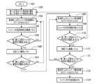
- FIG. 1 is a control flowchart of the control device for the battery parallel connection circuit according to the first embodiment (first embodiment).
- FIG. 2 is a system configuration diagram of a control device for a battery parallel connection circuit (Example 1).
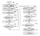
- FIG. 3 is a flowchart for control of the control device for the battery parallel connection circuit according to the second embodiment (second embodiment).
- FIG. 4 is a control flowchart of the control device for the battery parallel connection circuit according to the third embodiment (third embodiment).
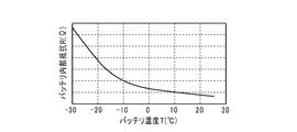
- FIG. 5 is a diagram illustrating the relationship between the battery temperature and the battery internal resistance (Example 3).
- FIG. 6 is a schematic circuit diagram of a parallel battery (Example 3).
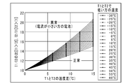
- FIG. 7 is a diagram illustrating determination criteria based on battery temperature difference and current ratio (Example 3).
- FIG. 2 shows a first embodiment of the present invention.
- 1 is a vehicle
- 2 is a control device for a battery parallel connection circuit mounted on the vehicle 1.
- the control device 2 of this battery parallel connection circuit is configured such that a plurality of, for example, two first and second secondary battery packs 3 and 4, which are provided in a substantially equivalent manner by combining small batteries, are connected in parallel with each other.
- Abnormality detection is performed by detecting and comparing the states of the first and second secondary battery packs 3 and 4. That is, as shown in FIG. 2, two first and second secondary battery packs 3 and 4 are provided by combining small batteries (also referred to as “small battery cells”) and connecting them in series.
- the second secondary battery packs 3 and 4 are connected in parallel to form the battery unit 5.
- the first secondary battery pack 3 is provided with a first state detection circuit 6 for detecting current or temperature (current in this first embodiment) and a first relay 7.
- the second secondary battery pack 4 is provided with a second state detection circuit 8 for detecting current or temperature (current in this first embodiment) and a second relay 9. That is, the battery unit 5 of the control device 2 of the battery parallel connection circuit connects the small batteries in series and mounts the first and second state detection circuits 6 and 8 and the first and second relays 7 and 9.
- the first and second secondary battery packs 3 and 4 are respectively configured.
- These two first and second secondary battery packs 3 and 4 and an air cooling fan (not shown) are collectively referred to as “battery unit 5”.
- the control apparatus 2 of the said battery parallel connection circuit is the 1st, 2nd state detection circuits 6 and 8 which detect the electric current of the said battery unit 5, and the said 1st, 2nd secondary battery packs 3 and 4,
- An inverter 10, a drive motor 11, and a control circuit (also referred to as “EV controller”) 12 that controls electric power and driving force of these devices are provided.
- the battery unit 5 is disposed between the rear wheels 1b and 1b of the vehicle 1 as shown in FIG.
- an inverter 10 and a control circuit 12 that are respectively connected to the battery unit 5 are disposed on the vehicle front side of the battery unit 5.
- the drive motor 11 connected to the inverter 10 is disposed between the front wheels 1 a and 1 a of the vehicle 1.
- control circuit 12 has a predetermined deviation and a predetermined value in the comparison between the currents detected corresponding to the first and second secondary battery packs 3 and 4 by the first and second state detection circuits 6 and 8. It has the structure which performs an electric current limitation based on the magnitude
- the control device 2 of the battery parallel connection circuit is provided with a blower fan 13 for cooling the first and second secondary battery packs 3 and 4.
- the control circuit 12 drives the blower fan 13 in accordance with the determination of the magnitude of the deviation. That is, the blower fan 13 mainly cools a large number of small batteries from the outside of the first and second secondary battery packs 3 and 4.
- one blower fan 13 is provided in common for the first and second secondary battery packs 3 and 4 and is distributed / joined by a blower duct (not shown).
- the first and second secondary battery packs 3 and 4 can be uniformly cooled. Therefore, in the control device 2 of the battery parallel connection circuit, the influence of the environmental temperature that easily causes a difference due to the mounting structure and arrangement of the first and second secondary battery packs 3 and 4 is reduced. Can be prevented.
- a status level is set for the current limit, and the control circuit 12 changes the drive level of the blower fan 13 in accordance with the current limit status level.
- the status level “0” indicates a state in the normal normal range
- the status level “1” indicates the weak abnormality state
- the status level “2” indicates the strong abnormality state. It shows that the state is getting worse as the number goes up (in other words, “depth increases”).
- the current limit also changes according to the status level number. The larger the number, the larger the limit width. Therefore, the accuracy can be gradually increased according to the depth of the status.
- the limit range of the current limit is gradually increased, so it is possible to travel for a while while receiving the current limit, and retreat travel (limp home travel) is performed.
- the battery unit 5 can be protected at the same time.
- control circuit 12 receives the current detected by the first and second state detection circuits 6 and 8 of the first and second secondary battery packs 3 and 4 during traveling. Then, the control circuit 12 calculates a current difference between the first and second secondary battery packs 3 and 4, and when the current difference exceeds a predetermined determination value, the control circuit 12 is traveling as shown in [Table 1] below. In accordance with the inverter current limit map according to the battery current difference, the status for limiting the drive current of the inverter 10 is incremented, and the control circuit 12 limits the current of the inverter 10 according to the limit.
- “According to battery 1 current limit and battery 2 current limit” described in Table 1 means that the control circuit 12 sets a predetermined limit value set in advance.
- control circuit 12 receives error information from the first and second state detection circuits 6 and 8 of the first and second secondary battery packs 3 and 4. When the control circuit 12 determines that one of the secondary battery packs has failed, only the relay of the normal secondary battery pack is turned ON to enable limp home travel.
- the control device 2 of the battery parallel connection circuit starts the current measurement of the first and second secondary battery packs 3 and 4 after the start of the current limit, and initially sets the inverter current limit at the status level “0”. Set the value (maximum) (see Table 1). And the control apparatus 2 of the said battery parallel connection circuit calculates the measured current difference, and compares whether this current difference exceeds predetermined determination value, for example, threshold value a. In this comparison, when the current difference does not exceed the threshold value a, the control device 2 of the battery parallel connection circuit maintains the status level at “0” while the current difference exceeds the threshold value a. Drives the blower fan 13 at the drive level “1” (weak).
- the control device 2 of the battery parallel connection circuit again compares the current difference with the threshold value a. If the current difference exceeds the threshold value a, the status level is set to “1” and the inverter current limit is set to the initial value. Half of Then, the control device 2 of the battery parallel connection circuit calculates the current difference measured by the first and second secondary battery packs 3 and 4 and compares whether the current difference exceeds the threshold value b. In this comparison, the control device 2 of the battery parallel connection circuit returns the status level to “0” when the current difference does not exceed the threshold value b, and when the current difference exceeds the threshold value b, The blower fan 13 is driven at a drive level “2” (strong). The control device 2 of the battery parallel connection circuit again compares the current difference with the threshold value b, and when the current difference exceeds the threshold value b, sets the status level to “2” and completely limits the current. (0A).
- control circuit 12 of the control device 2 of the battery parallel connection circuit executes a control program
- the control flowchart is started (101), and current limitation is started.
- the control circuit 12 starts the current detection of the first secondary battery pack 3 and the current detection of the second secondary battery pack 4 via the first and second state detection circuits 6 and 8. (102).
- the control circuit 12 sets the status level of the inverter current limit due to the current difference to “0” (103).
- the control circuit 12 sets the current limit of the inverter 10 to an initial value (104).
- the control circuit 12 determines whether or not the current difference between the first and second secondary battery packs 3 and 4 exceeds a predetermined determination value, for example, a threshold value a (105).
- control circuit 12 If this determination (105) is NO, the control circuit 12 returns to the above-described process (103), and sets the status level of the inverter current limit due to the current difference to “0” (103). On the other hand, if the determination (105) is YES, the control circuit 12 sets the drive level of the blower fan 13 to “1” (106).
- the control circuit 12 After the process (106) of setting the drive level of the blower fan 13 to “1”, the control circuit 12 causes the current difference between the first and second secondary battery packs 3 and 4 to exceed a predetermined determination value, for example, the threshold value a. It is judged whether or not (107). If this determination (107) is NO, the control circuit 12 returns to the above-described process (103), and sets the status level of the inverter current limit due to the current difference to “0” (103). On the other hand, if the determination (107) is YES, the control circuit 12 sets the status level of the inverter current limit due to the current difference to “1” (108). Next, the control circuit 12 halves the current limit of the inverter 10 (109).
- a predetermined determination value for example, the threshold value a.
- the control circuit 12 determines whether or not the current difference between the first and second secondary battery packs 3 and 4 exceeds a predetermined determination value, for example, a threshold value b (110). If this determination (110) is NO, the control circuit 12 returns to the above-described processing (102), and the first and second secondary battery packs 3 via the first and second state detection circuits 6 and 8. 4 starts current detection (102). On the other hand, if the determination (110) is YES, the control circuit 12 sets the drive level of the blower fan 13 to “2” (111).
- a predetermined determination value for example, a threshold value b (110).
- the control circuit 12 determines that the current difference between the first and second secondary battery packs 3 and 4 exceeds a predetermined determination value, for example, the threshold value b. It is determined whether or not (112). If this determination (112) is NO, the control circuit 12 returns to the above-described process (108), and sets the status level of the inverter current limit due to the current difference to “1” (108). On the other hand, if the determination (112) is YES, the control circuit 12 sets the status level of the inverter current limit due to the current difference to “2” (113). Next, the control circuit 12 sets the current limit of the inverter 10 to “0 A” (114).
- a predetermined determination value for example, the threshold value b.
- FIG. 3 shows a second embodiment of the present invention.
- portions that perform the same functions as those of the first embodiment will be described with the same reference numerals.
- control circuit 12 detects the first and second secondary battery packs 3 and 4 by the first and second state detection circuits 6 and 8.
- the current limit is based on the magnitude of the deviation between the difference between the two temperatures and the predetermined judgment value.
- control circuit 12 receives the temperatures detected by the first and second state detection circuits 6 and 8 of the first and second secondary battery packs 3 and 4 during traveling.
- the control circuit 12 calculates the temperature difference between the first and second secondary battery packs 3 and 4, and when the temperature difference exceeds a predetermined determination value, the battery in running shown in [Table 2] below
- the control circuit 12 increments the status for limiting the drive current of the inverter 10 according to the inverter current limit map according to the temperature difference, and the current of the inverter 10 is limited according to the limit.
- “According to battery 1 current limit and battery 2 current limit” described in Table 2 means that the control circuit 12 sets a predetermined limit value set in advance. Accordingly, the control circuit 12 detects an abnormality from the temperature difference between the first and second secondary battery packs 3 and 4 to prevent overdischarge and overcharge. In order not to be affected by the environmental temperature, the battery (3, 4) may be cooled by a certain amount of refrigerant.
- the blower fan 13 for cooling the first and second secondary battery packs 3 and 4 is provided in the control device 2 of the battery parallel connection circuit as in the first embodiment.
- the control circuit 12 drives the blower fan 13 in accordance with the determination of the magnitude of the deviation. Therefore, in the control device 2 of the battery parallel connection circuit, the influence of the environmental temperature that easily causes a difference due to the mounting structure and arrangement of the first and second secondary battery packs 3 and 4 is reduced. Can be prevented.
- a status level is set for the current limit, and the control circuit 12 changes the drive level of the blower fan 13 according to the current limit status level. . Therefore, the control circuit 12 can gradually increase the accuracy in accordance with the depth of the status.
- the control device 2 of the battery parallel connection circuit starts the temperature measurement of the first and second secondary battery packs 3 and 4 after starting the current limit, and initially sets the inverter current limit at the status level “0”. Set to value (maximum) (see Table 2). And the control apparatus 2 of the said battery parallel connection circuit calculates the measured temperature difference, and compares whether this temperature difference exceeds predetermined determination value, for example, threshold value a '. In this comparison, the control device 2 of the battery parallel connection circuit maintains the status level at “0” when the temperature difference does not exceed the threshold value a ′, while the temperature difference exceeds the threshold value a ′. In this case, the blower fan 13 is driven at the drive level “1” (weak).
- the control device 2 of the battery parallel connection circuit again compares the temperature difference with the threshold value a ′, and when the temperature difference exceeds the threshold value a ′, sets the status level to “1” and limits the inverter current. Set to half of the initial value.
- the control device 2 of the battery parallel connection circuit then calculates the measured temperature difference and compares whether the temperature difference exceeds the threshold value b ′. In this comparison, the control device 2 of the battery parallel connection circuit returns the status level to “0” when the temperature difference does not exceed the threshold value b ′, and when the temperature difference exceeds the threshold value b ′. Drives the blower fan 13 at the drive level “2” (strong).
- the control device 2 of the battery parallel connection circuit again compares the temperature difference with the threshold value b ′, and when the temperature difference exceeds the threshold value b ′, sets the status level to “2” and completely supplies the current. Limit (0A).
- control circuit 12 of the control device 2 of the battery parallel connection circuit executes the control program
- the control flowchart is started (201), and current limitation is started.
- the control circuit 12 starts temperature detection of the first secondary battery pack 3 via the first and second state detection circuits 6 and 8 and starts temperature detection of the second secondary battery pack 4. (202).
- the control circuit 12 sets the status level of the inverter current limit due to the temperature difference to “0” (203).
- the control circuit 12 sets the current limit of the inverter 10 to an initial value (204).
- the control circuit 12 determines whether or not the temperature difference between the first and second secondary battery packs 3 and 4 exceeds a predetermined determination value, for example, a threshold value a ′ (205).
- control circuit 12 When this determination (205) is NO, the control circuit 12 returns to the above-described processing (203), and sets the status level of the inverter current limit due to the temperature difference to “0” (203). On the other hand, if the determination (205) is YES, the control circuit 12 sets the drive level of the blower fan 13 to “1” (206).
- the control circuit 12 sets the temperature difference between the first and second secondary battery packs 3 and 4 to a predetermined determination value, for example, the threshold value a ′. It is judged whether or not it exceeds (207). If this determination (207) is NO, the control circuit 12 returns to the above-described processing (203), and sets the status level of the inverter current limit due to the temperature difference to “0” (203). On the other hand, when the determination (207) is YES, the control circuit 12 sets the status level of the inverter current limit due to the temperature difference to “1” (208). Next, the control circuit 12 halves the current limit of the inverter (209).
- a predetermined determination value for example, the threshold value a ′. It is judged whether or not it exceeds (207). If this determination (207) is NO, the control circuit 12 returns to the above-described processing (203), and sets the status level of the inverter current limit due to the temperature difference to “0” (203). On the other hand, when the determination (207) is YES, the
- the control circuit 12 determines whether or not the temperature difference between the first and second secondary battery packs 3 and 4 exceeds a predetermined determination value, for example, a threshold value b ′ (210).
- a predetermined determination value for example, a threshold value b ′ (210).
- the control circuit 12 returns to the above-described process (202), and the first and second secondary battery packs 3 are passed through the first and second state detection circuits 6 and 8. 4 starts temperature detection (202).
- the control circuit 12 sets the drive level of the blower fan 13 to “2” (211).
- the control circuit 12 sets the temperature difference between the first and second secondary battery packs 3 and 4 to a predetermined determination value, for example, the threshold value b ′. It is determined whether or not it exceeds (212). If this determination (212) is NO, the control circuit 12 returns to the above-described processing (208), and sets the status level of the inverter current limit due to the temperature difference to “1” (208). On the other hand, if the determination (212) is YES, the control circuit 12 sets the status level of the inverter current limit due to the temperature difference to “2” (213). Next, the control circuit 12 sets the current limit of the inverter 10 to “0 A” (214).
- a predetermined determination value for example, the threshold value b ′. It is determined whether or not it exceeds (212). If this determination (212) is NO, the control circuit 12 returns to the above-described processing (208), and sets the status level of the inverter current limit due to the temperature difference to “1” (208). On the other hand, if the determination
- the feature of the third embodiment is that the first and second state detection circuits 6 and 8 limit the current based on the current and temperature detected from the first and second secondary battery packs 3 and 4. It is in the point.
- the control circuit 12 determines the current ratio from the currents detected corresponding to the secondary battery packs 3 and 4 by the first and second state detection circuits 6 and 8. And the temperature deviation in the comparison between the temperatures detected corresponding to the secondary battery packs 3 and 4 by the first and second state detection circuits 6 and 8, and the calculated current ratio and the calculation The current is limited by comparing the current ratio determined from the temperature deviation. Therefore, the control circuit 12 detects an abnormality from the temperature difference and the current ratio to prevent overdischarge and overcharge. Further, the control circuit 12 can detect the presence / absence of abnormality in the overdischarge, overcharge, deterioration, and internal short circuit of the secondary battery pack, and can identify the secondary battery pack having the abnormality. That is, the control circuit 12 can cope with complex factors such as a factor caused by an abnormality in the secondary battery pack and an environmental factor caused by the secondary battery pack receiving heat from the outside.
- the blower fan 13 for cooling the secondary battery packs 3 and 4 is provided in the control device 2 of the battery parallel connection circuit.
- the control circuit 12 drives the blower fan 13 when determining the magnitude of the deviation.
- the control circuit 12 drives the blower fan 13
- the temperature difference between the first and second secondary battery packs 3 and 4 becomes smaller, and the temperature difference on the horizontal axis shown in FIG. Therefore, the influence of the temperature of the first and second secondary battery packs 3 and 4 itself can be reduced, and the accuracy can be ensured while suppressing the number of status levels. Therefore, the control device 2 of the battery parallel connection circuit improves the accuracy by reducing the influence of the environmental temperature that easily causes a difference depending on the mounting structure and arrangement of the first and second secondary battery packs 3 and 4. be able to.
- a status level is set for the current limit, and the control circuit 12 controls the drive level of the blower fan 13 according to the current limit status level. To change. Therefore, the control circuit 12 can gradually increase the accuracy in accordance with the depth of the status.
- FIG. 5 is a diagram showing the relationship between the battery temperature and the battery internal resistance.
- the internal resistance R can be expressed by Equation 1 below.
- I1 + I2 Relationship between current and internal resistance: I1 / I2 R2 / R1.
- I1 + I2 Relationship between current and internal resistance: I1 / I2 R2 / R1.
- the current flowing through the first and second secondary battery packs 3 and 4 is inversely proportional to the internal resistance.
- the control circuit 12 determines an abnormality based on a determination criterion for a current ratio (I1 / I2) obtained from a battery temperature difference (T1-T2).
- a determination line for each temperature which is a determination criterion based on the battery temperature difference and the current ratio, is disclosed in FIG.
- the horizontal axis is the temperature difference
- the horizontal axis is the current ratio
- a plurality of determination lines are shown. The determination line is set according to the lower temperature of the first and second secondary battery packs 3 and 4.
- the control circuit 12 of the control device 2 of the battery parallel connection circuit executes the control program
- the control flowchart is started (301) and the current limitation is started.
- the control circuit 12 starts to detect the current and temperature of the first secondary battery pack 3 via the first and second state detection circuits 6 and 8, and also detects the current and temperature of the second secondary battery pack 4. Temperature detection is started (302).
- the control circuit 12 sets the status level of the inverter current limit to “0” (303).
- the control circuit 12 sets the current limit of the inverter 10 to an initial value (304).
- the control circuit 12 calculates a temperature difference and a current ratio (305).
- the control circuit 12 determines whether or not the current ratio exceeds the determination line disclosed in FIG. 7 (306).
- control circuit 12 If this determination (306) is NO, the control circuit 12 returns to the above-described process (303) and sets the status level of the inverter current limit to “0” (303). On the other hand, if the determination (306) is YES, the control circuit 12 sets the drive level of the blower fan 13 to “1” (307).
- the control circuit 12 calculates the temperature difference and the current ratio again (308), and the current ratio is disclosed in the determination line disclosed in FIG. It is determined whether or not it exceeds (309). If this determination (309) is NO, the control circuit 12 returns to the above-described processing (303) and sets the status level of the inverter current limit to “0” (303). On the other hand, if the determination (309) is YES, the control circuit 12 sets the status level of the inverter current limit to “1” (310). Next, the control circuit 12 halves the current limit of the inverter 10 (311).
- the control circuit 12 again calculates the temperature difference and the current ratio (312), and determines whether or not the current ratio exceeds the determination line disclosed in FIG. 7 (313).
- this determination (313) is NO
- the control circuit 12 returns to the above-described process (302), and the first and second secondary battery packs 3 are connected via the first and second state detection circuits 6 and 8. 4 starts current and temperature detection (302).
- the control circuit 12 sets the drive level of the blower fan 13 to “2” (314).
- the control circuit 12 calculates the temperature difference and the current ratio again (315), and the current ratio is disclosed in the determination line disclosed in FIG. It is determined whether or not it exceeds (316). If this determination (316) is NO, the control circuit 12 returns to the above-described processing (310) and sets the status level of the inverter current limit to “1” (310). On the other hand, if the determination (316) is YES, the control circuit 12 sets the status level of the inverter current limit due to the temperature difference to “2” (317). Next, the control circuit 12 sets the current limit of the inverter to “0 A” (318).
- the control circuit 12 when the control circuit 12 calculates the current difference between the first and second secondary battery packs 3 and 4 and the current difference exceeds a predetermined determination value, According to the current limit map of [Table 1], the status for limiting the drive current of the inverter 10 is incremented, and the current of the inverter 10 is limited according to the limit.
- the control circuit 12 when the control circuit 12 calculates the temperature difference between the first and second secondary battery packs 3 and 4 and the temperature difference exceeds a predetermined determination value, [Table 2 ], The status for limiting the drive current of the inverter 10 is incremented according to the current limit map, and the inverter current is limited according to the limit.
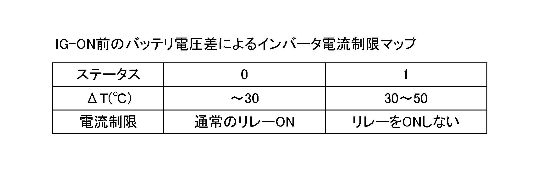
- control circuit 12 may have a special configuration that takes into account the voltage difference between the first and second secondary battery packs 3 and 4. That is, when a difference occurs between the voltages of the first and second secondary battery packs 3 and 4 before the ignition is turned on, the control circuit 12 is an inverter based on a battery voltage difference before the ignition is turned on as shown in [Table 3] below. Control the relay according to the current limit map. For example, if the temperature difference between the first and second secondary battery packs 3 and 4 is 30 (° C.) or less, the control circuit 12 turns on the relays 7 and 9 as usual. If the temperature difference is larger than 30 (° C.) and 50 (° C.) or less, the control circuit 12 does not turn on the relays 7 and 9. The control circuit 12 may turn on only the relays 7 and 9 corresponding to the first and second secondary battery packs 3 and 4 having a smaller voltage.
- the current limit according to [Table 1] in the first embodiment and the current limit according to [Table 2] in the second embodiment have a predetermined limit value set in advance. As a percentage change to the current limit. For example, in the status “0”, the predetermined limit value becomes the current limit as it is, whereas in the status “1”, half of the predetermined limit value becomes the current limit. Stopping means setting the current limit to “0”.
- blower fan 13 may be individually provided in the plurality of secondary battery packs 3 and 4, and when provided individually, drive control is performed so that the plurality of secondary battery packs can be uniformly cooled. You can do it.
- the inverter current limit status level is set in three stages from “0” to “2”, but this status level is subdivided to increase the number of levels.
- a special configuration is also possible. By increasing the number of levels, the inverter current limit can be finely performed according to the subdivided status level, which can contribute to the improvement of the current limit accuracy.
- the state detection circuits 6 and 8 and the relays 7 and 9 are stored in the secondary battery packs 3 and 4.
- the state detection circuit and the relay are separately arranged. It is also possible to adopt a configuration. Although detailed description is omitted, it is possible to adopt a configuration in which the state detection circuit and the relay are housed in a DC / DC converter, a junction box, or the like provided in the battery unit.
- the first embodiment using the current difference and the second embodiment using the temperature difference have been described as separate embodiments.
- the temperature difference between the first embodiment using the current difference and the first embodiment is described. It is also possible to use both the second embodiment to be used in combination, and to make a new embodiment by adding changes such as combining one with priority.
- the present invention is an electric vehicle having a battery as a drive energy source, such as an electric vehicle (also referred to as “EV”), a hybrid vehicle (also referred to as “HEV”), and a plug-in hybrid vehicle (also referred to as “PHEV”). Can be used.
- a battery as a drive energy source
- EV electric vehicle
- HEV hybrid vehicle
- PHEV plug-in hybrid vehicle
Landscapes
- Engineering & Computer Science (AREA)
- Power Engineering (AREA)
- Mechanical Engineering (AREA)
- Transportation (AREA)
- Life Sciences & Earth Sciences (AREA)
- Sustainable Energy (AREA)
- Sustainable Development (AREA)
- Chemical & Material Sciences (AREA)
- General Chemical & Material Sciences (AREA)
- Electrochemistry (AREA)
- Chemical Kinetics & Catalysis (AREA)
- Manufacturing & Machinery (AREA)
- Secondary Cells (AREA)
- Charge And Discharge Circuits For Batteries Or The Like (AREA)
- Electric Propulsion And Braking For Vehicles (AREA)
Abstract
Description
近時、小型のバッテリセルの普及が進み、小型のバッテリセルの組み電流パックを組み合わせ、複数並列接続することで容量を確保しつつ、搭載する際の構造ではバッテリユニットの設計自由度を拡大させている。
しかし、複数並列接続された電池パックの内部短絡や劣化、過放電、過充電の異常判定は、環境温度の影響を受け、確実な異常判定が難しいという不都合がある。
例えば、上記の特許文献1に開示されるものにおいては、電池温度を比較することで過放電、過充電を判定しているが、内部短絡と劣化の異常を判定することは難しいものである。
また、小型バッテリを組み合わせ互いにほぼ等価に設けた複数の二次電池パックを互いに並列となるように接続し、これら二次電池パックの状態について検知および比較を行って異常検出を行う電池並列接続回路の制御装置であって、それぞれの二次電池パックに電流および温度を検出する状態検出回路を設け、前記制御装置の制御回路は、前記状態検出回路により前記二次電池パックに対応して検出された電流どうしからその電流比を算出するとともに、前記状態検出回路により前記二次電池パックに対応して検出された温度どうしの比較における温度偏差を算出し、算出した電流比と、算出した温度偏差から定まる電流比の判定値と、を比較することにより電流制限を行うことを特徴とする。
従って、二次電池パックどうしの温度差や電流差から異常を検出して、過放電、過充電を防止できる。
また、小型バッテリを組み合わせ互いにほぼ等価に設けた複数の二次電池パックを互いに並列となるように接続し、これら二次電池パックの状態について検知および比較を行って異常検出を行う電池並列接続回路の制御装置であって、それぞれの二次電池パックに電流および温度を検出する状態検出回路を設け、制御回路は、前記状態検出回路により前記二次電池パックに対応して検出された電流どうしからその電流比を算出するとともに、前記状態検出回路により前記二次電池パックに対応して検出された温度どうしの比較における温度偏差を算出し、算出した電流比と、算出した温度偏差から定まる電流比の判定値と、を比較することにより電流制限を行う。
従って、温度差および電流比から異常を検出して、過放電、過充電を防止できる。
また、二次電池パックの過放電、過充電、劣化、内部短絡について異常の有無を検出でき、異常のある二次電池パックを特定できる。
図2において、1は車両、2は車両1に搭載される電池並列接続回路の制御装置である。
この電池並列接続回路の制御装置2は、小型バッテリを組み合わせ互いにほぼ等価に設けた複数、例えば2個の第1、第2二次電池パック3、4を互いに並列となるように接続され、これら第1、第2二次電池パック3、4の状態について検知および比較を行って異常検出を行うものである。
つまり、図2に示す如く、小型バッテリ(「小型バッテリセル」ともいう。)を組み合わせて直列接続して2個の第1、第2二次電池パック3、4を設け、これらの第1、第2二次電池パック3、4を並列接続してバッテリユニット5を形成している。
このとき、第1二次電池パック3に、電流又は温度(この第1実施例においては電流)を検出する第1状態検出回路6と、第1リレー7とを設ける。
また、第2二次電池パック4には、電流又は温度(この第1実施例においては電流)を検出する第2状態検出回路8と、第2リレー9とを設ける。
つまり、前記電池並列接続回路の制御装置2のバッテリユニット5は、小型バッテリを直列に接続し、前記第1、第2状態検出回路6、8と第1、第2リレー7、9とを実装して第1、第2二次電池パック3、4を夫々構成している。
これらの2個の第1、第2二次電池パック3、4と空冷ファン(図示せず)などを総称して、「バッテリユニット5」とする。
そして、前記電池並列接続回路の制御装置2は、前記バッテリユニット5と、前記第1、第2二次電池パック3、4の電流を検出する第1、第2状態検出回路6、8と、インバータ10と、駆動用モータ11と、これらのデバイスの電力と駆動力を制御する制御回路(「EVコントローラ」ともいう。)12を備えている。
このとき、前記バッテリユニット5は、図2に示す如く、車両1の後輪1b、1b間に配設される。また、このバッテリユニット5の車両前側には、バッテリユニット5に夫々接続するインバータ10と制御回路12とが配設される。更に、前記車両1の前輪1a、1a間には、インバータ10に接続する前記駆動用モータ11が配設される。
詳述すれば、前記制御回路12は、前記バッテリユニット5に対する前記インバータ10及び前記駆動用モータ11が消費する電流を制限する。
そして、前記制御回路12は、前記バッテリユニット5に対する前記インバータ10及び前記駆動用モータ11が発電する電流を制限する。
従って、前記制御回路12は、前記第1、第2二次電池パック3、4どうしの電流差から異常を検出して、過放電、過充電を防止する。
つまり、送風ファン13は、前記第1、第2二次電池パック3、4に対し、その外部から、主に多数の小型バッテリを冷却するものである。
このとき、詳細には図示しないが、送風ファン13は、第1、第2二次電池パック3、4に共通して1つ設けてあり、送風ダクト(図示せず)によって分配/合流させて第1、第2二次電池パック3、4を均等に冷却することができる。
従って、前記電池並列接続回路の制御装置2では、前記第1、第2二次電池パック3、4の搭載構造や配置などによって差を生み易い環境温度の影響を低減し、過放電、過充電を防止できる。
このとき、ステータスレベルにおいて、ステータスレベル「0」が通常の正常範囲内にある状態を示し、ステータスレベル「1」が弱異常状態、ステータスレベル「2」が強異常状態のように、ステータスレベルの数字が上がる(「深度が大きくなる」とも換言できる。)に連れて状態が悪化していることを示す。
そして、ステータスレベルの数字に応じて、電流制限も変わり、数字が大きくなる程、制限幅も大きくなる。
従って、ステータスの深度に応じて徐々に精度を高めることができる。
なお、異常判定のステータスレベルが進むに従い、徐々に電流制限の制限幅が大きくなるようにしているので、電流制限を受けつつも暫くの間は走行が可能となり、退避走行(リンプホーム走行)が可能となる一方、前記バッテリユニット5の保護との両立ができる。
そして、制御回路12は、前記第1、第2二次電池パック3、4の電流差を算出し、電流差が所定の判定値を超えた場合に、以下の[表1]に示す走行中のバッテリ電流差によるインバータ電流制限マップに従って前記インバータ10の駆動電流を制限するステータスをインクリメントし、前記制御回路12はその制限に従い、インバータ10の電流を制限する。

例えば、a=50(A)、b=75(A)、c=100(A)等とする。表1に記載の「バッテリ1電流制限およびバッテリ2電流制限に従う」とは、制御回路12が予め設定した所定の制限値にすることを意味する。
そして、前記電池並列接続回路の制御装置2は、計測した電流差を計算し、この電流差が所定の判定値、例えば閾値aを超えているかを比較する。
前記電池並列接続回路の制御装置2は、この比較において、電流差が閾値aを超えていない場合には、ステータスレベルを「0」に維持する一方、電流差が閾値aを超えている場合には、前記送風ファン13を駆動レベル「1」(弱)で駆動する。
前記電池並列接続回路の制御装置2は、再度、電流差と閾値aとを比較し、電流差が閾値aを超えている場合には、ステータスレベルを「1」とし、インバータ電流制限を初期値の半分とする。
前記電池並列接続回路の制御装置2は、その後、前記第1、第2二次電池パック3、4の計測した電流差を計算し、この電流差が閾値bを超えているかを比較する。
前記電池並列接続回路の制御装置2は、この比較において、電流差が閾値bを超えていない場合には、ステータスレベルを「0」へ戻し、電流差が閾値bを超えている場合には、前記送風ファン13を駆動レベル「2」(強)で駆動する。
前記電池並列接続回路の制御装置2は、再度、電流差と閾値bとを比較し、電流差が閾値bを超えている場合には、ステータスレベルを「2」とし、電流を完全に制限する(0A)。
まず、制御回路12は、第1、第2状態検出回路6、8を介して前記第1二次電池パック3の電流検出を開始するとともに、前記第2二次電池パック4の電流検出を開始する(102)。
次に、制御回路12は、電流差によるインバータ電流制限のステータスレベルを「0」にセットする(103)。
次に、制御回路12は、前記インバータ10の電流制限を初期値にする(104)。
次に、制御回路12は、前記第1、第2二次電池パック3、4の電流差が所定の判定値、例えば閾値aを超えているか否かを判断する(105)。
この判断(105)がNOの場合には、制御回路12は、上述した処理(103)に戻り、電流差によるインバータ電流制限のステータスレベルを「0」にセットする(103)。
一方、判断(105)がYESの場合には、制御回路12は、前記送風ファン13の駆動レベルを「1」とする(106)。
この判断(107)がNOの場合には、制御回路12は、上述した処理(103)に戻り、電流差によるインバータ電流制限のステータスレベルを「0」にセットする(103)。
一方、判断(107)がYESの場合には、制御回路12は、電流差によるインバータ電流制限のステータスレベルを「1」にセットする(108)。
次に、制御回路12は、前記インバータ10の電流制限を半分にする(109)。
次に、制御回路12は、前記第1、第2二次電池パック3、4の電流差が所定の判定値、例えば閾値bを超えているか否かを判断する(110)。
この判断(110)がNOの場合には、制御回路12は、上述した処理(102)に戻り、第1、第2状態検出回路6、8を介して第1、第2二次電池パック3、4の電流検出を開始する(102)。
一方、判断(110)がYESの場合には、制御回路12は、前記送風ファン13の駆動レベルを「2」とする(111)。
この判断(112)がNOの場合には、制御回路12は、上述した処理(108)に戻り、電流差によるインバータ電流制限のステータスレベルを「1」にセットする(108)。
一方、判断(112)がYESの場合には、制御回路12は、電流差によるインバータ電流制限のステータスレベルを「2」にセットする(113)。
次に、制御回路12は、前記インバータ10の電流制限を「0A」にする(114)。
この第2実施例において、上述第1実施例のものと同一機能を果たす箇所には、同一符号を付して説明する。
制御回路12は、前記第1、第2二次電池パック3、4の温度差を算出し、温度差が所定の判定値を超えた場合に、以下の[表2]に示す走行中のバッテリ温度差によるインバータ電流制限マップに従って前記インバータ10の駆動電流を制限するステータスをインクリメントし、前記制御回路12はその制限に従い、インバータ10の電流を制限する。
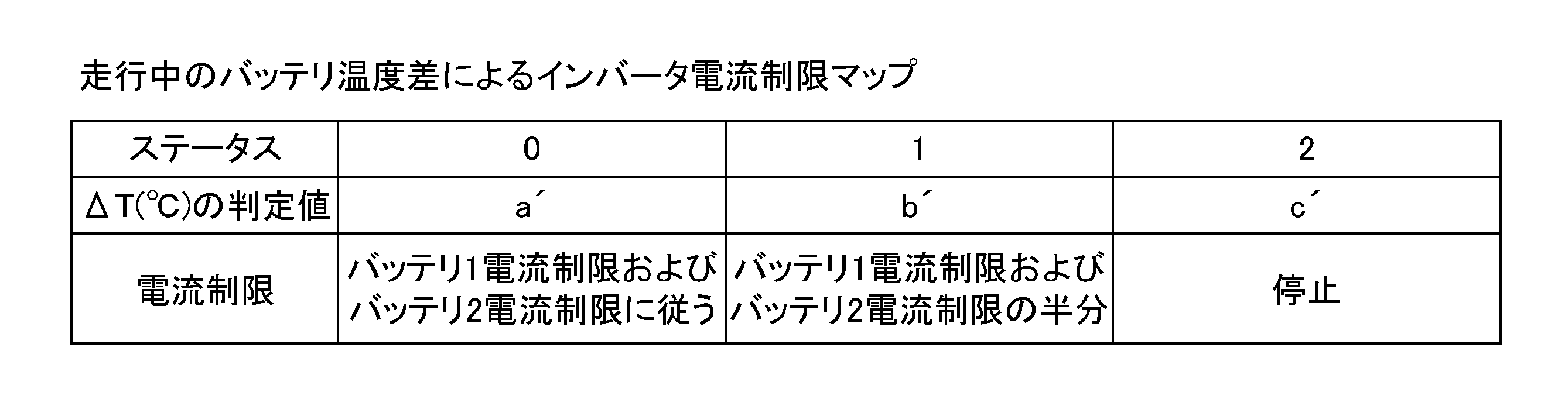
例えば、a’=10(℃)、b’=15(℃)、c’=20(℃)等とする。表2に記載の「バッテリ1電流制限およびバッテリ2電流制限に従う」とは、制御回路12が予め設定した所定の制限値にすることを意味する。
従って、前記制御回路12は、前記第1、第2二次電池パック3、4どうしの温度差から異常を検出して、過放電、過充電を防止する。
なお、環境温度の影響を受けないようにするために、一定量の冷媒によってバッテリ(3、4)を冷却する構成とすることも可能である。
従って、前記電池並列接続回路の制御装置2では、前記第1、第2二次電池パック3、4の搭載構造や配置などによって差を生み易い環境温度の影響を低減し、過放電、過充電を防止できる。
従って、前記制御回路12は、ステータスの深度に応じて徐々に精度を高めることができる。
そして、前記電池並列接続回路の制御装置2は、計測した温度差を計算し、この温度差が所定の判定値、例えば閾値a’を超えているかを比較する。
前記電池並列接続回路の制御装置2は、この比較において、温度差が閾値a’を超えていない場合には、ステータスレベルを「0」に維持する一方、温度差が閾値a’を超えている場合には、前記送風ファン13を駆動レベル「1」(弱)で駆動する。
前記電池並列接続回路の制御装置2は、再度、温度差と閾値a’とを比較し、温度差が閾値a’を超えている場合には、ステータスレベルを「1」とし、インバータ電流制限を初期値の半分とする。
前記電池並列接続回路の制御装置2は、その後、計測した温度差を計算し、この温度差が閾値b’を超えているかを比較する。
前記電池並列接続回路の制御装置2は、この比較において、温度差が閾値b’を超えていない場合には、ステータスレベルを「0」へ戻し、温度差が閾値b’を超えている場合には、前記送風ファン13を駆動レベル「2」(強)で駆動する。
前記電池並列接続回路の制御装置2は、再度、温度差と閾値b’とを比較し、温度差が閾値b’を超えている場合には、ステータスレベルを「2」とし、電流を完全に制限する(0A)。
まず、制御回路12は、第1、第2状態検出回路6、8を介して前記第1二次電池パック3の温度検出を開始するとともに、前記第2二次電池パック4の温度検出を開始する(202)。
次に、制御回路12は、温度差によるインバータ電流制限のステータスレベルを「0」にセットする(203)。
次に、制御回路12は、前記インバータ10の電流制限を初期値にする(204)。
次に、制御回路12は、前記第1、第2二次電池パック3、4の温度差が所定の判定値、例えば閾値a’を超えているか否かを判断する(205)。
この判断(205)がNOの場合には、制御回路12は、上述した処理(203)に戻り、温度差によるインバータ電流制限のステータスレベルを「0」にセットする(203)。
一方、判断(205)がYESの場合には、制御回路12は、前記送風ファン13の駆動レベルを「1」とする(206)。
この判断(207)がNOの場合には、制御回路12は、上述した処理(203)に戻り、温度差によるインバータ電流制限のステータスレベルを「0」にセットする(203)。
一方、判断(207)がYESの場合には、制御回路12は、温度差によるインバータ電流制限のステータスレベルを「1」にセットする(208)。
次に、制御回路12は、前記インバータの電流制限を半分にする(209)。
次に、制御回路12は、前記第1、第2二次電池パック3、4の温度差が所定の判定値、例えば閾値b’を超えているか否かを判断する(210)。
この判断(210)がNOの場合には、制御回路12は、上述した処理(202)に戻り、第1、第2状態検出回路6、8を介して第1、第2二次電池パック3、4の温度検出を開始する(202)。
一方、判断(210)がYESの場合には、制御回路12は、前記送風ファン13の駆動レベルを「2」とする(211)。
この判断(212)がNOの場合には、制御回路12は、上述した処理(208)に戻り、温度差によるインバータ電流制限のステータスレベルを「1」にセットする(208)。
一方、判断(212)がYESの場合には、制御回路12は、温度差によるインバータ電流制限のステータスレベルを「2」にセットする(213)。
次に、制御回路12は、前記インバータ10の電流制限を「0A」にする(214)。
従って、前記制御回路12は、温度差および電流比から異常を検出して、過放電、過充電を防止する。また、前記制御回路12は、二次電池パックの過放電、過充電、劣化、内部短絡について異常の有無を検出でき、異常のある二次電池パックを特定できる。すなわち、前記制御回路12は、二次電池パックが異常による要因および二次電池パックが外部から熱を受けることによる環境要因等の複合要因に対応することができる。
そして、前記制御回路12が送風ファン13を駆動すると、前記第1、第2二次電池パック3、4どうしの温度差が小さくなり、後述する図7に示す横軸の温度差が向かって左側に寄ることになり、前記第1、第2二次電池パック3、4自体の温度の影響を小さくでき、ステータスレベルの数を抑制しつつ、精度を確保することができる。
従って、前記電池並列接続回路の制御装置2では、前記第1、第2二次電池パック3、4の搭載構造や配置などによって差を生み易い環境温度の影響を低減して、精度を向上することができる。
従って、前記制御回路12は、ステータスの深度に応じて徐々に精度を高めることができる。
このとき、内部抵抗Rは、以下の式1にて示すことができる。
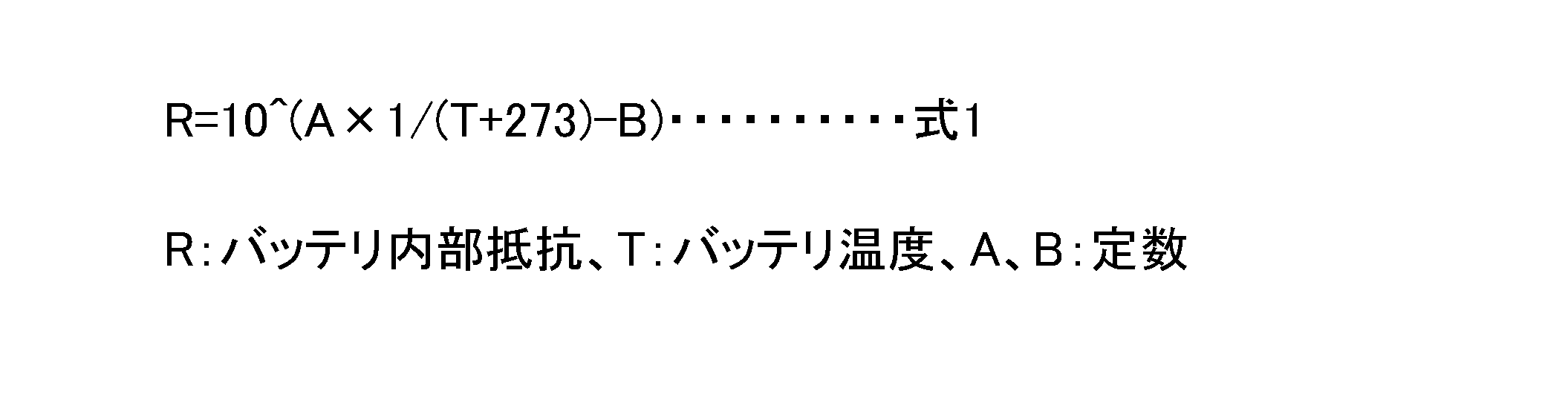
図6では、
I:インバータ電流
I1:第1バッテリ電流
I2:第2バッテリ電流
R1:第1バッテリ内部抵抗
R2:第2バッテリ内部抵抗
T1:第1バッテリ温度
T2:第2バッテリ温度
このとき、電流の関係:I=I1+I2
電流と内部抵抗の関係:I1/I2=R2/R1である。
この図6の概略回路図において、第1、第2二次電池パック3、4に流れる電流は、内部抵抗に反比例する。このことを利用して、前記制御回路12は、電池の温度差(T1-T2)から求められる電流比(I1/I2)の判定基準に基づいて異常を判定する。
このとき、バッテリ温度差と電流比での判定基準である温度毎での判定ラインを図7に開示する。図7では、横軸が温度差であり、横軸が電流比であり、複数の判定ラインが示されている。判定ラインは第1、第2二次電池パック3、4のうち低い方の温度に応じて設定されている。
まず、制御回路12は、第1、第2状態検出回路6、8を介して前記第1二次電池パック3の電流及び温度検出を開始するとともに、前記第2二次電池パック4の電流及び温度検出を開始する(302)。
次に、制御回路12は、インバータ電流制限のステータスレベルを「0」にセットする(303)。
次に、制御回路12は、前記インバータ10の電流制限を初期値にする(304)。
次に、制御回路12は、温度差と電流比とを算出する(305)。
次に、制御回路12は、電流比が図7に開示される判定ラインを超えているか否かを判断する(306)。
この判断(306)がNOの場合には、制御回路12は、上述した処理(303)に戻り、インバータ電流制限のステータスレベルを「0」にセットする(303)。
一方、判断(306)がYESの場合には、制御回路12は、前記送風ファン13の駆動レベルを「1」とする(307)。
この判断(309)がNOの場合には、制御回路12は、上述した処理(303)に戻り、インバータ電流制限のステータスレベルを「0」にセットする(303)。
一方、判断(309)がYESの場合には、制御回路12は、インバータ電流制限のステータスレベルを「1」にセットする(310)。
次に、制御回路12は、前記インバータ10の電流制限を半分にする(311)。
次に、制御回路12は、再度、温度差と電流比とを算出し(312)、電流比が図7に開示される判定ラインを超えているか否かを判断する(313)。
この判断(313)がNOの場合には、制御回路12は、上述した処理(302)に戻り、第1、第2状態検出回路6、8を介して第1、第2二次電池パック3、4の電流及び温度検出を開始する(302)。
一方、判断(313)がYESの場合には、制御回路12は、前記送風ファン13の駆動レベルを「2」とする(314)。
この判断(316)がNOの場合には、制御回路12は、上述した処理(310)に戻り、インバータ電流制限のステータスレベルを「1」にセットする(310)。
一方、判断(316)がYESの場合には、制御回路12は、温度差によるインバータ電流制限のステータスレベルを「2」にセットする(317)。
次に、制御回路12は、前記インバータの電流制限を「0A」にする(318)。
すなわち、前記制御回路12はイグニッションON前に前記第1、第2二次電池パック3、4の電圧に差が発生する場合、以下の[表3]に示すイグニッションON前のバッテリ電圧差によるインバータ電流制限マップに従ってリレーを制御する。例えば、第1、第2二次電池パック3、4の温度差が30(℃)以下であれば、前記制御回路12は通常通りリレー7、9をONにする。また、温度差が30(℃)よりも大きく、50(℃)以下であれば、前記制御回路12はリレー7、9をONにしない。なお、前記制御回路12は電圧が小さい方の前記第1、第2二次電池パック3、4に対応するリレー7、9のみをONにしてもよい。
例えば、ステータス「0」で所定の制限値がそのまま電流制限となるのに対し、ステータス「1」では所定の制限値の半分が電流制限となる。
停止とは電流制限を「0」とすることである。
レベル数を増加させることで、細分化されたステータスレベルによってインバータ電流制限を細かく行うことができ、電流制限精度の向上に寄与し得る。
なお、詳細説明は省略するが、バッテリユニットに併設するDC/DCコンバータやジャンクションボックスなどに前記状態検出回路やリレーを収める構成とすることも可能である。
Claims (6)
- 小型バッテリを組み合わせ互いにほぼ等価に設けた複数の二次電池パックを互いに並列となるように接続し、これら二次電池パックの状態について検知および比較を行って異常検出を行う電池並列接続回路の制御装置であって、
それぞれの二次電池パックに電流又は温度を検出する状態検出回路を設け、
制御回路は、前記状態検出回路により前記二次電池パックに対応して検出された電流どうしの比較又は前記状態検出回路により前記二次電池パックに対応して検出された温度どうしの比較のうち少なくとも一方の比較における偏差と所定の判定値との偏差の大きさに基づいて電流制限を行うことを特徴とする電池並列接続回路の制御装置。 - 前記二次電池パックを冷却する送風ファンが設けられ、
前記制御回路は、偏差の大きさの判定に伴って前記送風ファンを駆動することを特徴とする請求項1に記載の電池並列接続回路の制御装置。 - 前記制御回路は、電流制限にステータスレベルを設定し、電流制限のステータスレベルに応じて前記送風ファンの駆動レベルを変更することを特徴とする請求項2に記載の電池並列接続回路の制御装置。
- 小型バッテリを組み合わせ互いにほぼ等価に設けた複数の二次電池パックを互いに並列となるように接続し、これら二次電池パックの状態について検知および比較を行って異常検出を行う電池並列接続回路の制御装置であって、
それぞれの二次電池パックに電流および温度を検出する状態検出回路を設け、
制御回路は、前記状態検出回路により前記二次電池パックに対応して検出された電流どうしからその電流比を算出するとともに、前記状態検出回路により前記二次電池パックに対応して検出された温度どうしの比較における温度偏差を算出し、算出した電流比と、算出した温度偏差から定まる電流比の判定値と、を比較することにより電流制限を行うことを特徴とする電池並列接続回路の制御装置。 - 前記二次電池パックを冷却する送風ファンが設けられ、
前記制御回路は、前記算出した電流比と前記判定値との比較結果に伴って前記送風ファンを駆動することを特徴とする請求項4に記載の電池並列接続回路の制御装置。 - 前記制御回路は、電流制限にステータスレベルを設定し、電流制限のステータスレベルに応じて前記送風ファンの駆動レベルを変更することを特徴とする請求項5に記載の電池並列接続回路の制御装置。
Priority Applications (3)
| Application Number | Priority Date | Filing Date | Title |
|---|---|---|---|
| DE201111101823 DE112011101823T5 (de) | 2010-05-28 | 2011-04-27 | Kontrollsystem für eine parallele Batterieanschlussschaltung |
| CN201180026182.4A CN102934318B (zh) | 2010-05-28 | 2011-04-27 | 电池并联连接电路的控制系统 |
| US13/700,212 US20130140886A1 (en) | 2010-05-28 | 2011-04-27 | Control system for parallel battery connection circuit |
Applications Claiming Priority (2)
| Application Number | Priority Date | Filing Date | Title |
|---|---|---|---|
| JP2010122578A JP5477778B2 (ja) | 2010-05-28 | 2010-05-28 | 電池並列接続回路の制御装置 |
| JP2010-122578 | 2010-05-28 |
Publications (1)
| Publication Number | Publication Date |
|---|---|
| WO2011148752A1 true WO2011148752A1 (ja) | 2011-12-01 |
Family
ID=45003744
Family Applications (1)
| Application Number | Title | Priority Date | Filing Date |
|---|---|---|---|
| PCT/JP2011/060223 Ceased WO2011148752A1 (ja) | 2010-05-28 | 2011-04-27 | 電池並列接続回路の制御装置 |
Country Status (5)
| Country | Link |
|---|---|
| US (1) | US20130140886A1 (ja) |
| JP (1) | JP5477778B2 (ja) |
| CN (1) | CN102934318B (ja) |
| DE (1) | DE112011101823T5 (ja) |
| WO (1) | WO2011148752A1 (ja) |
Cited By (3)
| Publication number | Priority date | Publication date | Assignee | Title |
|---|---|---|---|---|
| FR2992928A1 (fr) * | 2012-07-06 | 2014-01-10 | Renault Sa | Dispositif de gestion de batterie modulaire. |
| CN104681892A (zh) * | 2015-02-09 | 2015-06-03 | 清华大学 | 电池微短路的识别方法 |
| JP2019517102A (ja) * | 2016-09-09 | 2019-06-20 | エルジー・ケム・リミテッド | バッテリーパック故障検出装置および方法 |
Families Citing this family (32)
| Publication number | Priority date | Publication date | Assignee | Title |
|---|---|---|---|---|
| JP5626195B2 (ja) * | 2011-12-16 | 2014-11-19 | トヨタ自動車株式会社 | 蓄電システム |
| JP2013183524A (ja) * | 2012-03-01 | 2013-09-12 | Toyota Motor Corp | 電動車両およびその制御方法 |
| US9318901B2 (en) | 2012-11-30 | 2016-04-19 | Tesla Motors, Inc. | Response to detection of an overdischarge event in a series connected battery element |
| US9153990B2 (en) * | 2012-11-30 | 2015-10-06 | Tesla Motors, Inc. | Steady state detection of an exceptional charge event in a series connected battery element |
| US9343911B2 (en) | 2012-11-30 | 2016-05-17 | Tesla Motors, Inc. | Response to detection of an overcharge event in a series connected battery element |
| EP2821276A1 (de) * | 2013-07-02 | 2015-01-07 | Xtronic Gmbh | Energieversorgungsvorrichtung mit parallel geschalteten Batterie Modulen, Elektromotor und Fahrzeug |
| RU2627239C1 (ru) | 2013-08-09 | 2017-08-04 | Хитачи Аутомотив Системс, Лтд. | Система управления аккумуляторной батареей и система управления транспортным средством |
| US9287726B2 (en) * | 2013-11-06 | 2016-03-15 | The Boeing Company | Virtual cell for battery thermal management |
| US10116158B2 (en) * | 2013-12-23 | 2018-10-30 | Cameron International Corporation | Power management system with selective source depletion |
| FR3029639B1 (fr) * | 2014-12-08 | 2018-11-30 | Dcns | Procede et dispositif de detection d'une surcharge d'un accumulateur d'une batterie |
| DE102015200406A1 (de) | 2015-01-14 | 2016-07-14 | Robert Bosch Gmbh | Prognose interner Kurzschlüsse eines Batteriemoduls |
| DE102015110183A1 (de) * | 2015-06-24 | 2016-12-29 | Phoenix Contact Gmbh & Co. Kg | Messanordnung zum Erkennen einer Fehlfunktion in einer Energiespeicheranordnung |
| CN105207290B (zh) * | 2015-09-15 | 2017-08-22 | 浙江超威创元实业有限公司 | 并联电池的控制装置及控制方法 |
| CN108432081A (zh) * | 2015-12-31 | 2018-08-21 | 深圳市大疆创新科技有限公司 | 用于管理电池组件的方法和系统 |
| KR102523045B1 (ko) * | 2016-01-12 | 2023-04-17 | 삼성전자주식회사 | 고장 셀 검출 장치 및 방법 |
| CN106114249A (zh) * | 2016-05-19 | 2016-11-16 | 杭州伯坦科技工程有限公司 | 电动汽车并联电池箱上下电控制系统及控制方法 |
| JP6565940B2 (ja) * | 2017-01-17 | 2019-08-28 | トヨタ自動車株式会社 | 車両 |
| DE102017204065A1 (de) * | 2017-03-13 | 2018-09-13 | Robert Bosch Gmbh | Antriebssystem für ein Fahrzeug und Verfahren zum Betrieb eines Antriebssystems |
| US10992144B2 (en) * | 2017-05-17 | 2021-04-27 | Galley Power LLC | Battery balancing and current control with bypass circuit for load switch |
| JP6546617B2 (ja) * | 2017-05-18 | 2019-07-17 | 矢崎総業株式会社 | 電力分配システム |
| CN107799848B (zh) * | 2017-11-13 | 2023-11-21 | 河南森源电气股份有限公司 | 一种电池储能设备及其热管理系统 |
| DE102018200145A1 (de) * | 2018-01-08 | 2019-07-11 | Robert Bosch Gmbh | Verfahren zur Erkennung eines internen Kurzschlusses in einer ersten elektrischen Energiespeichereinheit eines elektrischen Energiespeichers |
| JP6962826B2 (ja) * | 2018-01-16 | 2021-11-05 | トヨタ自動車株式会社 | 電池システム |
| KR102606004B1 (ko) * | 2018-07-26 | 2023-11-27 | 삼성전자주식회사 | 전자 장치 및 그 배터리 관리 방법 |
| DE102019200032A1 (de) * | 2019-01-04 | 2020-07-09 | Robert Bosch Gmbh | Verfahren zum Betreiben eines Batteriesystems und Batteriesystem |
| KR102710752B1 (ko) * | 2019-01-31 | 2024-09-27 | 삼성전자주식회사 | 복수의 배터리들의 충전을 제어하는 방법 및 그 방법을 적용한 전자 장치 |
| JP7120062B2 (ja) * | 2019-02-07 | 2022-08-17 | トヨタ自動車株式会社 | 組電池の充放電制御装置および組電池の充放電制御方法 |
| CN113655396B (zh) * | 2020-05-12 | 2022-10-18 | 比亚迪股份有限公司 | 诊断电池包动力回路连接状态的方法和系统及管理系统 |
| JP7528552B2 (ja) * | 2020-06-12 | 2024-08-06 | トヨタ自動車株式会社 | 電池システム |
| JP2022045569A (ja) * | 2020-09-09 | 2022-03-22 | ヤマハ発動機株式会社 | 船舶推進システムおよび舶用電源システム |
| JPWO2022249916A1 (ja) * | 2021-05-28 | 2022-12-01 | ||
| FR3131779B1 (fr) * | 2022-01-13 | 2023-12-29 | Psa Automobiles Sa | Surveillance de l’isolement électrique d’une ligne de recharge d’une batterie principale d’un véhicule |
Citations (4)
| Publication number | Priority date | Publication date | Assignee | Title |
|---|---|---|---|---|
| JPH06283210A (ja) * | 1993-01-29 | 1994-10-07 | Canon Inc | 蓄電装置及び電力システム |
| JP2001185228A (ja) * | 1999-12-24 | 2001-07-06 | Sanyo Electric Co Ltd | 電池を備える電源装置 |
| JP2008099541A (ja) * | 2006-10-16 | 2008-04-24 | Samsung Sdi Co Ltd | バッテリー管理システム、およびバッテリー管理システムの駆動方法 |
| JP2008118790A (ja) * | 2006-11-06 | 2008-05-22 | Hitachi Ltd | 電源制御装置 |
Family Cites Families (16)
| Publication number | Priority date | Publication date | Assignee | Title |
|---|---|---|---|---|
| US2965830A (en) * | 1956-12-17 | 1960-12-20 | Thomas G Isel | Temperature responsive control for battery charging circuit |
| JP2756611B2 (ja) | 1990-06-26 | 1998-05-25 | 松下電工 株式会社 | ワイヤレス防犯システム |
| US5266792A (en) * | 1991-10-28 | 1993-11-30 | Simmonds Precision Products, Inc. | Temperature compensated optical detector |
| US5263050A (en) * | 1992-09-09 | 1993-11-16 | Echelon Corporation | Adaptive threshold in a spread spectrum communications system |
| EP0609101B1 (en) * | 1993-01-29 | 2002-06-26 | Canon Kabushiki Kaisha | Electric power accumulating apparatus and electric power system |
| JPH08140206A (ja) * | 1994-11-09 | 1996-05-31 | Fuji Heavy Ind Ltd | 電気自動車のバッテリ管理方法 |
| JP2704133B2 (ja) * | 1995-05-22 | 1998-01-26 | 日本電気テレコムシステム株式会社 | レーザダイオード駆動回路 |
| JP3378189B2 (ja) * | 1998-02-28 | 2003-02-17 | 株式会社マキタ | 充電装置及び充電方法 |
| JP4053289B2 (ja) * | 2001-12-12 | 2008-02-27 | 本田技研工業株式会社 | 蓄電池の温度制御装置、及びそれを用いた車両装置 |
| CA2567944A1 (en) * | 2004-07-12 | 2006-01-19 | Hydrogenics Corporation | Adaptive current controller for a fuel-cell system |
| TWI238039B (en) * | 2004-09-10 | 2005-08-11 | Compal Electronics Inc | The method for controlling the fan speed by detecting different power sources of the mobile electronics device |
| JP4254783B2 (ja) * | 2006-01-27 | 2009-04-15 | トヨタ自動車株式会社 | ハイブリッド制御装置 |
| WO2008095313A1 (en) * | 2007-02-09 | 2008-08-14 | Advanced Lithium Power Inc. | Battery thermal management system |
| US7746613B1 (en) * | 2007-02-28 | 2010-06-29 | Maxim Integrated Products, Inc. | Method and apparatus for providing an adaptive current limiter |
| US20090153100A1 (en) * | 2007-12-14 | 2009-06-18 | Fujitsu Limited | Charging control apparatus controlling charging current and control method therefore |
| US9093847B2 (en) * | 2010-02-12 | 2015-07-28 | Nec Energy Solutions, Inc. | Temperature controlled parallel balancing |
-
2010
- 2010-05-28 JP JP2010122578A patent/JP5477778B2/ja active Active
-
2011
- 2011-04-27 WO PCT/JP2011/060223 patent/WO2011148752A1/ja not_active Ceased
- 2011-04-27 DE DE201111101823 patent/DE112011101823T5/de active Pending
- 2011-04-27 US US13/700,212 patent/US20130140886A1/en not_active Abandoned
- 2011-04-27 CN CN201180026182.4A patent/CN102934318B/zh active Active
Patent Citations (4)
| Publication number | Priority date | Publication date | Assignee | Title |
|---|---|---|---|---|
| JPH06283210A (ja) * | 1993-01-29 | 1994-10-07 | Canon Inc | 蓄電装置及び電力システム |
| JP2001185228A (ja) * | 1999-12-24 | 2001-07-06 | Sanyo Electric Co Ltd | 電池を備える電源装置 |
| JP2008099541A (ja) * | 2006-10-16 | 2008-04-24 | Samsung Sdi Co Ltd | バッテリー管理システム、およびバッテリー管理システムの駆動方法 |
| JP2008118790A (ja) * | 2006-11-06 | 2008-05-22 | Hitachi Ltd | 電源制御装置 |
Cited By (4)
| Publication number | Priority date | Publication date | Assignee | Title |
|---|---|---|---|---|
| FR2992928A1 (fr) * | 2012-07-06 | 2014-01-10 | Renault Sa | Dispositif de gestion de batterie modulaire. |
| CN104681892A (zh) * | 2015-02-09 | 2015-06-03 | 清华大学 | 电池微短路的识别方法 |
| JP2019517102A (ja) * | 2016-09-09 | 2019-06-20 | エルジー・ケム・リミテッド | バッテリーパック故障検出装置および方法 |
| US10892527B2 (en) | 2016-09-09 | 2021-01-12 | Lg Chem, Ltd. | Apparatus and method for detecting failure of battery pack |
Also Published As
| Publication number | Publication date |
|---|---|
| US20130140886A1 (en) | 2013-06-06 |
| CN102934318B (zh) | 2015-03-04 |
| JP2011250622A (ja) | 2011-12-08 |
| JP5477778B2 (ja) | 2014-04-23 |
| CN102934318A (zh) | 2013-02-13 |
| DE112011101823T5 (de) | 2013-03-14 |
Similar Documents
| Publication | Publication Date | Title |
|---|---|---|
| JP5477778B2 (ja) | 電池並列接続回路の制御装置 | |
| JP6540781B2 (ja) | 蓄電装置 | |
| US7830126B2 (en) | Hybrid vehicle control system and method | |
| US7492129B2 (en) | Temperature abnormality detecting apparatus and method for secondary battery | |
| US11554687B2 (en) | Power supply system and management device capable of determining current upper limit for supressing cell deterioration and ensuring safety | |
| US11532841B2 (en) | Storage battery control device | |
| US9573580B2 (en) | Charge control device for hybrid vehicle | |
| JP6802723B2 (ja) | 蓄電装置および蓄電制御方法 | |
| JP2008099541A (ja) | バッテリー管理システム、およびバッテリー管理システムの駆動方法 | |
| JP6800758B2 (ja) | 二次電池の制御装置及び二次電池の制御方法 | |
| JP5974914B2 (ja) | 電池システム及び電池の状態判定の設定変更方法 | |
| JP2015076958A (ja) | 蓄電システム | |
| WO2016147572A1 (ja) | 電池管理装置、および電源装置 | |
| JP2008062913A (ja) | バッテリー管理システム及びバッテリー管理システムの駆動方法 | |
| KR101316186B1 (ko) | 절연파괴 검출에 따른 주행제어방법 | |
| CN103813928A (zh) | 电池的处理装置、车辆、电池的处理方法及电池的处理程序 | |
| JP5477304B2 (ja) | 電源システムおよびそれを搭載する車両、ならびに電源システムの制御方法 | |
| JP2012011896A (ja) | ハイブリッドカーの電源装置 | |
| CN113752840B (zh) | 电池系统 | |
| JP6312474B2 (ja) | 車両用電源システム | |
| US12388271B2 (en) | Cell equalization system | |
| JP2020061823A (ja) | 二次電池制御装置 | |
| JP2013137935A (ja) | 非水二次電池の制御装置および制御方法 | |
| JP2012221927A (ja) | 蓄電池温度調節装置の制御装置 | |
| JP5978144B2 (ja) | 蓄電池システム |
Legal Events
| Date | Code | Title | Description |
|---|---|---|---|
| WWE | Wipo information: entry into national phase |
Ref document number: 201180026182.4 Country of ref document: CN |
|
| 121 | Ep: the epo has been informed by wipo that ep was designated in this application |
Ref document number: 11786452 Country of ref document: EP Kind code of ref document: A1 |
|
| WWE | Wipo information: entry into national phase |
Ref document number: 9144/DELNP/2012 Country of ref document: IN |
|
| WWE | Wipo information: entry into national phase |
Ref document number: 112011101823 Country of ref document: DE Ref document number: 1120111018231 Country of ref document: DE |
|
| WWE | Wipo information: entry into national phase |
Ref document number: 13700212 Country of ref document: US |
|
| 122 | Ep: pct application non-entry in european phase |
Ref document number: 11786452 Country of ref document: EP Kind code of ref document: A1 |