WO2011145593A1 - 固体撮像素子用の撮像レンズ - Google Patents
固体撮像素子用の撮像レンズ Download PDFInfo
- Publication number
- WO2011145593A1 WO2011145593A1 PCT/JP2011/061264 JP2011061264W WO2011145593A1 WO 2011145593 A1 WO2011145593 A1 WO 2011145593A1 JP 2011061264 W JP2011061264 W JP 2011061264W WO 2011145593 A1 WO2011145593 A1 WO 2011145593A1
- Authority
- WO
- WIPO (PCT)
- Prior art keywords
- lens
- object side
- focal length
- imaging
- imaging lens
- Prior art date
- Legal status (The legal status is an assumption and is not a legal conclusion. Google has not performed a legal analysis and makes no representation as to the accuracy of the status listed.)
- Ceased
Links
Images


Classifications
-
- G—PHYSICS
- G02—OPTICS
- G02B—OPTICAL ELEMENTS, SYSTEMS OR APPARATUS
- G02B9/00—Optical objectives characterised both by the number of the components and their arrangements according to their sign, i.e. + or -
- G02B9/34—Optical objectives characterised both by the number of the components and their arrangements according to their sign, i.e. + or - having four components only
-
- G—PHYSICS
- G02—OPTICS
- G02B—OPTICAL ELEMENTS, SYSTEMS OR APPARATUS
- G02B13/00—Optical objectives specially designed for the purposes specified below
- G02B13/001—Miniaturised objectives for electronic devices, e.g. portable telephones, webcams, PDAs, small digital cameras
- G02B13/0015—Miniaturised objectives for electronic devices, e.g. portable telephones, webcams, PDAs, small digital cameras characterised by the lens design
- G02B13/002—Miniaturised objectives for electronic devices, e.g. portable telephones, webcams, PDAs, small digital cameras characterised by the lens design having at least one aspherical surface
- G02B13/004—Miniaturised objectives for electronic devices, e.g. portable telephones, webcams, PDAs, small digital cameras characterised by the lens design having at least one aspherical surface having four lenses
-
- G—PHYSICS
- G02—OPTICS
- G02B—OPTICAL ELEMENTS, SYSTEMS OR APPARATUS
- G02B13/00—Optical objectives specially designed for the purposes specified below
- G02B13/001—Miniaturised objectives for electronic devices, e.g. portable telephones, webcams, PDAs, small digital cameras
- G02B13/0015—Miniaturised objectives for electronic devices, e.g. portable telephones, webcams, PDAs, small digital cameras characterised by the lens design
Definitions
- the present invention relates to an imaging lens for a solid-state imaging device used in a small imaging device used in a small and thin electronic device.
- the present invention relates to an imaging lens for a solid-state imaging device used in a compact imaging device used in a small and thin electronic device such as a portable terminal or PDA (Personal Digital Assistance).
- a portable terminal or PDA Personal Digital Assistance
- the image pickup lens is also required to have higher performance in terms of resolution and image quality.
- imaging lenses composed of a plurality of lenses are becoming common.
- an imaging lens having a four-lens configuration that can achieve higher performance than a two- to three-lens configuration has been proposed.
- an aperture stop in order from the object side, an aperture stop, a first lens having a positive refractive power, a second lens having a negative refractive power, and a third lens having a positive refractive power.
- an imaging lens which has a configuration of a fourth lens having at least one aspherical surface and having negative refractive power, aiming at high performance.
- Patent Document 4 discloses, in order from the object side, an aperture stop, a biconvex first lens having a positive refractive power, and a second meniscus shape having a negative refractive power with a convex surface facing the object side.
- a lens By disposing a lens, a meniscus third lens having a positive refractive power with a convex surface facing the image side, and a meniscus fourth lens having a negative refractive power with a convex surface facing the object side, An imaging lens aiming at high performance is disclosed.
- Patent Documents 1 to 4 aim for high performance by adopting a four-lens configuration, it is sufficient to cope with downsizing and thinning, or correction of various aberrations. I can not say.
- the present invention has been made in view of the circumstances described above, and an object of the present invention is to obtain an imaging lens that has a short optical length, can be miniaturized, corrects various aberrations, has high performance, and can cope with cost reduction. .
- the present invention has been supplemented with specific embodiments since the invention of the basic idea, and has been filed as an invention summarized here.
- An imaging lens for a solid-state imaging device includes, in order from the object side, a first lens having a positive refractive power with a convex surface facing the object side in the vicinity of the optical axis, and a concave surface on the object side and the image side in the vicinity of the optical axis.
- a fourth lens having a biconcave lens shape, and satisfying the following conditional expressions (1) and (2).
- an aperture stop is disposed on the object side of the first lens.
- the image side surface of the second lens does not have an inflection point from the center to the periphery of the lens, and has an aspherical shape that changes uniformly. It is characterized by.
- the object side surface of the fourth lens does not have an inflection point from the center to the periphery of the lens and has an aspherical shape that changes uniformly. It is characterized by.
- the second lens satisfies the following conditional expression (3). -2.05 ⁇ f2 / f ⁇ -0.5 (3)
- f total focal length of the entire imaging lens
- f2 focal length of the second lens
- the fourth lens satisfies the following conditional expression (4). -1.2 ⁇ f4 / f ⁇ -0.35 (4)
- f total focal length of the entire imaging lens
- f4 focal length of the fourth lens
- the second lens and the fourth lens further satisfy both of the following conditional expressions (3) and (4). -2.05 ⁇ f2 / f ⁇ -0.5 (3) -1.2 ⁇ f4 / f ⁇ -0.35 (4)
- f total focal length of the entire imaging lens
- f2 focal length of the second lens
- f4 focal length of the fourth lens
- the fourth lens satisfies the following conditional expression (5) with respect to the curvature radii on the object side and the image side. -0.61 ⁇ r8 / r7 ⁇ 0.0 (5)
- r7 radius of curvature of the fourth lens object side surface
- r8 radius of curvature of the fourth lens image side surface
- the first lens satisfies the following conditional expression (6). 0.4 ⁇ f1 / f ⁇ 0.8 (6)
- f Composite focal length of the entire imaging lens
- f1 Focal length of the first lens
- the third lens satisfies the following conditional expression (7). 0.35 ⁇ f3 / f ⁇ 0.9 (7)
- f Composite focal length of the entire imaging lens
- f3 Focal length of the third lens
- the first lens and the third lens satisfy both of the following conditional expressions (6) and (7).
- f Composite focal length f1 of the entire imaging lens
- f1 Focal length f3 of the first lens: Focal length of the third lens
- the second lens satisfies the following conditional expression (8) with respect to the radius of curvature of the object side and the image side. -2.0 ⁇ r4 / r3 ⁇ 0.0 (8)
- r3 radius of curvature of the second lens object side surface
- r4 radius of curvature of the second lens image side surface
- the imaging lens for a solid-state imaging device is characterized in that the following conditional expression (9) is satisfied with respect to the optical length and focal length of the imaging optical system. 1.03 ⁇ L / f ⁇ 1.4 (9)
- L Distance on the optical axis from the side surface of the first lens object to the image plane (air equivalent distance excluding parallel plane glass)
- f Composite focal length of the entire imaging lens system
- a first lens having a positive refractive power with a convex surface facing the object side in the vicinity of the optical axis, and the object side and the image in the vicinity of the optical axis.
- a bi-concave lens-shaped second lens having a concave surface facing the side, a meniscus third lens having a positive refractive power facing the image side near the optical axis, and an object side and an image side near the optical axis
- a fourth lens having a biconcave lens shape with a concave surface, and satisfies the following conditional expressions (10) and (2a).
- At least one of the first lens, the second lens, the third lens, and the fourth lens has an aspherical shape, and is made of a synthetic resin material. It is a so-called plastic lens.
- the present invention it is easy to ensure off-axis performance by disposing the aperture stop on the most object side and giving the fourth lens with a four-lens configuration a role that was not in the conventional three-lens configuration. Yes.
- the present invention by arranging a negative power lens in the fourth lens, it becomes easy to correct lateral chromatic aberration, which was insufficiently corrected with the conventional three-lens lens, and high performance can be achieved. .
- the present invention provides a first lens having a positive refractive power with a convex surface facing the object side in the vicinity of the optical axis, and a second lens having a biconcave lens shape with a concave surface facing the object side and the image side in the vicinity of the optical axis.
- a third meniscus lens having a positive refractive power with the convex surface facing the image side in the vicinity of the optical axis, and a fourth lens having a biconcave lens shape with the concave surface facing the object side and the image side near the optical axis In addition, by optimizing the distribution of the refractive power of each lens, various aberrations can be corrected well, and the performance and size of the lens can be improved. Further, the cost can be reduced by using a resin material.
- the negative power of the second lens and the fourth lens is increased, and the positive power of the first lens and the third lens is increased according to the negative power of the second lens and the fourth lens.
- FIG. 1 It is an aberration diagram which the imaging lens for solid-state image sensors of the 3rd Example of this invention tends to achieve. It is sectional drawing of the imaging lens for solid-state image sensors of Example 4 (a) and Example 4 (b) as a 4th Example. It is an aberration diagram which the imaging lens for solid-state image sensors of the 4th Example of this invention tends to achieve. It is the schematic which shows the positional relationship of the aperture stop and the 1st lens in Example 3 (a) and Example 3 (b). It is the schematic which shows the positional relationship of the aperture stop and Example 1 in Example 4 (a) and Example 4 (b). It is sectional drawing of the imaging lens for solid-state image sensors of Example 1 (c) as a 1st Example. FIG.
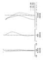
- Example 6 is a diagram illustrating various aberrations to be achieved by the imaging lens for the solid-state imaging element according to Example 1 (c) of the present invention. It is sectional drawing of the imaging lens for solid-state image sensors of Example 2 (c) as a 2nd Example. It is an aberration diagram which the imaging lens for solid-state image sensors of Example 2 (c) of the present invention intends to achieve. It is sectional drawing of the imaging lens for solid-state image sensors of Example 3 (c) as a 3rd Example. It is various aberration diagrams which the imaging lens for solid-state image sensors of Example 3 (c) of the present invention tries to achieve. It is sectional drawing of the imaging lens for solid-state image sensors of Example 4 (c) as a 4th Example. It is various aberration diagrams which the imaging lens for solid-state image sensors of Example 4 (c) of the present invention intends to achieve.
- the present invention for solving the problems described above can solve the problems by configuring the imaging lens as follows.
- the present invention is a photographing lens for a solid-state imaging device, and in order from the object side, a first lens having a positive refractive power with a convex surface facing the object side near the optical axis, and an object side and an image side near the optical axis.
- a second lens in the shape of a biconcave lens with a concave surface facing the lens, a third meniscus lens having a positive refractive power facing the image side near the optical axis, and a concave surface on the object side and the image side near the optical axis And satisfies the following conditional expressions (1) and (2).
- the conditional expression (1) defines the lens shape of the first lens. If the lower limit of conditional expression (1) is exceeded, the positive power of the image side surface of the first lens becomes too strong, and spherical aberration occurs on this surface, making it difficult to ensure sufficient on-axis performance. Conversely, if the upper limit is exceeded, the first lens becomes a meniscus shape, but if it is within the range of conditional expression (1), the positive power of the object side surface becomes too strong, and this surface has a high error sensitivity. The problem of becoming is less likely to occur.
- conditional expression (1) it was found that by replenishing the examples, more reliable effects can be expected if the examples are in the range of the following conditional expression (1a). -1.0 ⁇ r1 / r2 ⁇ 0.0 (1a)
- conditional expression (2) defines the lens shape of the third lens.
- the positive power of the third lens becomes strong, so that the optical length cannot be shortened, and the imaging lens, which is one of the objects of the present invention, is reduced in size and thickness. Contrary.
- the positive power of the third lens becomes too weak, and the balance between on-axis performance and off-axis performance is lost, making it difficult to ensure performance.
- conditional expression (2) it has been found that, by replenishing the embodiment, more reliable effects can be expected if the embodiment is in the range of the following conditional expression (2a). 0.12 ⁇ r6 / r5 ⁇ 1.0 (2a)
- the aperture stop is disposed on the object side of the first lens.
- CRA Choef Ray Angle
- the image side surface of the second lens has an aspherical shape that does not have an inflection point from the center to the periphery of the lens and changes uniformly.
- the object side surface of the fourth lens has an aspherical shape that does not have an inflection point from the center to the periphery of the lens and changes uniformly.
- the second lens satisfies the following conditional expression (3). -2.05 ⁇ f2 / f ⁇ -0.5 (3)
- f total focal length of the entire imaging lens
- f2 focal length of the second lens
- conditional expression (3) it has been found that, by replenishing the embodiment, a more reliable effect can be expected if the embodiment is in the range of the following conditional expression (3a). -1.3 ⁇ f2 / f ⁇ -0.5 (3a)
- the fourth lens satisfies the following conditional expression (4). -1.2 ⁇ f4 / f ⁇ -0.35 (4)
- f total focal length of the entire imaging lens
- f4 focal length of the fourth lens
- conditional expression (4) it has been found that, by replenishing the embodiment, a more reliable effect can be expected if the embodiment is in the range of the following conditional expression (4a). ⁇ 0.95 ⁇ f4 / f ⁇ 0.35 (4a)
- the second lens and the fourth lens satisfy both the following conditional expressions (3) and (4) simultaneously. -2.05 ⁇ f2 / f ⁇ -0.5 (3) -1.2 ⁇ f4 / f ⁇ -0.35 (4)
- f total focal length of the entire imaging lens
- f2 focal length of the second lens
- f4 focal length of the fourth lens
- conditional expression (3) defines the focal length range of the second lens with respect to the focal length of the entire system.
- the focal length of the second lens becomes too long, making it difficult to correct axial chromatic aberration.
- the focal length of the second lens becomes too short, making it difficult to correct spherical aberration and coma, and in either case, desired optical performance cannot be obtained.
- conditional expression (4) defines the focal length range of the fourth lens with respect to the focal length of the entire system.
- the optical length becomes long, which is contrary to the reduction in size and thickness of the imaging lens that is the object of the present invention.
- the focal length of the fourth lens becomes too short, making it difficult to ensure off-axis performance, and the error sensitivity characteristics at low image heights deteriorate.
- conditional expressions (3) and (4) by replenishing the embodiment, if the embodiment is in the range of the following conditional expressions (3a) and (4a), a more reliable effect can be expected. I understood. -1.3 ⁇ f2 / f ⁇ -0.5 (3a) ⁇ 0.95 ⁇ f4 / f ⁇ 0.35 (4a)
- the fourth lens satisfies the following conditional expression (5) regarding the curvature radii of the object side and the image side. -0.61 ⁇ r8 / r7 ⁇ 0.0 (5)
- r7 radius of curvature of the fourth lens object side surface
- r8 radius of curvature of the fourth lens image side surface
- the conditional expression (5) defines the lens shape of the fourth lens.
- the lower limit of conditional expression (5) is exceeded, the negative power on the object side surface of the fourth lens becomes too strong, and the balance between on-axis performance and off-axis performance is lost, making it difficult to ensure performance.
- the upper limit is exceeded, the fourth lens shape becomes a meniscus shape, and there remains a problem with the lens configuration that has existed in the past, and there is a lens shape that can realize cost reduction while maintaining the high performance intended by the present invention. It will not be achieved.
- conditional expression (5) it was found that, by replenishing the example, a more reliable effect can be expected if the example is in the range of the following conditional expression (5a). -0.2 ⁇ r8 / r7 ⁇ 0.0 (5a)
- the first lens satisfies the following conditional expression (6). 0.4 ⁇ f1 / f ⁇ 0.8 (6)
- f Composite focal length of the entire imaging lens
- f1 Focal length of the first lens
- conditional expression (6) it was found that by replenishing the example, a more reliable effect can be expected if the example is in the range of the following conditional expression (6a). 0.4 ⁇ f1 / f ⁇ 0.75 (6a)
- the third lens satisfies the following conditional expression (7). 0.35 ⁇ f3 / f ⁇ 0.9 (7)
- f Composite focal length of the entire imaging lens
- f3 Focal length of the third lens
- conditional expression (7) it was found that by replenishing the example, a more certain effect can be expected if the example is in the range of the following conditional expression (7a). 0.4 ⁇ f3 / f ⁇ 0.85 (7a)
- the first lens and the third lens satisfy both of the following conditional expressions (6) and (7).
- f Composite focal length f1 of the entire imaging lens
- f1 Focal length f3 of the first lens: Focal length of the third lens
- conditional expression (6) defines the focal length range of the first lens with respect to the focal length of the entire system.
- the focal length of the first lens becomes too short, making it difficult to correct spherical aberration and coma.
- the optical length becomes too long, which is contrary to the downsizing / thinning of the imaging lens that is the object of the present invention.
- conditional expression (7) defines the focal length range of the third lens with respect to the focal length of the entire system. If the lower limit of conditional expression (7) is exceeded, the focal length of the third lens will be too short, it will be difficult to correct coma and astigmatism, the error sensitivity will be large, and very high accuracy will be required during production. The Conversely, if the upper limit is exceeded, the power of the third lens will be insufficient, and the correction of off-axis aberration will be insufficient.
- conditional expressions (6) and (7) by replenishing the embodiment, if the embodiment falls within the following conditional expressions (6a) and (7a), a more reliable effect can be expected. I understood. 0.4 ⁇ f1 / f ⁇ 0.75 (6a) 0.4 ⁇ f3 / f ⁇ 0.85 (7a)
- the second lens satisfies the following conditional expression (8) regarding the curvature radii of the object side and the image side. -2.0 ⁇ r4 / r3 ⁇ 0.0 (8)
- r3 radius of curvature of the second lens object side surface
- r4 radius of curvature of the second lens image side surface
- the conditional expression (8) defines the lens shape of the second lens.
- the lower limit of conditional expression (8) is exceeded, the negative power on the object side surface of the second lens becomes too strong, and the error sensitivity becomes severe, resulting in a lens with poor productivity.
- the upper limit is exceeded, the second lens shape becomes a meniscus shape, and there remains a problem of the lens configuration that has existed in the past, and a lens shape that can realize cost reduction while maintaining the high performance intended by the present invention. It will not be achieved.
- conditional expression (9) defines the optical length in relation to the focal length.
- the optical length becomes too short, making it difficult to correct various aberrations, and the error sensitivity at the time of manufacture becomes too severe.
- the optical length becomes too long, which is contrary to the downsizing and thinning of the imaging lens that is the object of the present invention.
- conditional expression (9a) 1.03 ⁇ L / f ⁇ 1.25
- the imaging lens for a solid-state imaging device includes, in order from the object side, a first lens having a positive refractive power with a convex surface facing the object side near the optical axis, and an object side and an image side near the optical axis.
- the present invention is a so-called plastic lens in which at least one of the first lens, the second lens, the third lens, and the fourth lens has an aspherical shape and is made of a resin material.
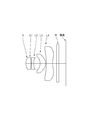
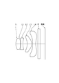
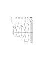
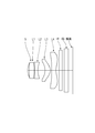
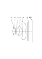
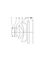
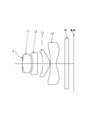
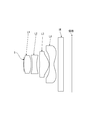
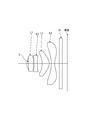
- the aperture stop S, the first lens L1, the second lens L2, the third lens L3, and the fourth lens from the object side. L4, parallel plane glass IR, and an image plane are arranged in this order.
- the aperture stop S of the first and second embodiments is set on the object side surface of the first lens (FIG. 9), and the aperture stop S of the third and fourth embodiments is It is set at a position closer to the image side than the object side surface of the first lens (FIG. 10).
- the aspherical shape in each embodiment is expressed by the following aspherical expression, where the apex of the surface is the origin, the Z axis is taken in the optical axis direction, and the height in the direction perpendicular to the optical axis is h.
- Numerical data are shown in Table 1 for the imaging lens of Example 1 (a) of the first example. 1 is a sectional view of the imaging lens, and FIG. 2 is a diagram showing various aberrations.
- Table 5 shows numerical data of the imaging lens of Example 1 (b) of the first example. 1 is a sectional view of the imaging lens, and FIG. 2 is a diagram showing various aberrations.
- FIG. 11 is a sectional view of the imaging lens
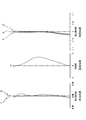
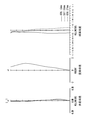
- FIG. 12 is a diagram showing various aberrations.
- Table 2 shows numerical data of the imaging lens of Example 2 (a) of the second example.
- 3 is a sectional view of the imaging lens
- FIG. 4 is a diagram showing various aberrations.
- Numerical data are shown in Table 6 for the imaging lens of Example 2 (b) of the second example.
- 3 is a sectional view of the imaging lens
- FIG. 4 is a diagram showing various aberrations.
- Table 10 shows numerical data of the imaging lens of Example 2 (c) of the second example.
- FIG. 13 is a sectional view of the imaging lens
- FIG. 14 is a diagram showing various aberrations.
- Table 3 shows numerical data of the imaging lens of Example 3 (a) of the third example. 5 is a sectional view of the imaging lens, and FIG. 6 is a diagram showing various aberrations.
- Table 7 shows numerical data of the imaging lens of Example 3 (b) of the third example. 5 is a sectional view of the imaging lens, and FIG. 6 is a diagram showing various aberrations.
- Table 11 shows numerical data of the imaging lens of Example 3 (c) of the third example.
- FIG. 15 is a sectional view of the imaging lens
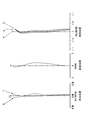
- FIG. 16 is a diagram showing various aberrations.
- Table 4 shows numerical data of the imaging lens of Example 4 (a) of the fourth example.
- FIG. 7 is a sectional view of the imaging lens
- FIG. 8 is a diagram showing various aberrations.
- FIG. 7 is a sectional view of the imaging lens
- FIG. 8 is a diagram showing various aberrations.
- Table 12 shows numerical data of the imaging lens of Example 4 (c) of the fourth example.
- FIG. 17 is a sectional view of the imaging lens
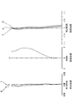
- FIG. 18 is a diagram showing various aberrations.
Landscapes
- Physics & Mathematics (AREA)
- General Physics & Mathematics (AREA)
- Optics & Photonics (AREA)
- Lenses (AREA)
Priority Applications (2)
| Application Number | Priority Date | Filing Date | Title |
|---|---|---|---|
| CN201190000497.7U CN203191626U (zh) | 2010-05-17 | 2011-05-17 | 固体摄像元件用的摄像镜头 |
| US13/677,484 US8730594B2 (en) | 2010-05-17 | 2012-11-15 | Image pickup lens for solid-state image pickup element |
Applications Claiming Priority (4)
| Application Number | Priority Date | Filing Date | Title |
|---|---|---|---|
| JP2010-112980 | 2010-05-17 | ||
| JP2010112980 | 2010-05-17 | ||
| JP2011-107602 | 2011-05-12 | ||
| JP2011107602A JP5797007B2 (ja) | 2010-05-17 | 2011-05-12 | 固体撮像素子用の撮像レンズ |
Related Child Applications (1)
| Application Number | Title | Priority Date | Filing Date |
|---|---|---|---|
| US13/677,484 Continuation US8730594B2 (en) | 2010-05-17 | 2012-11-15 | Image pickup lens for solid-state image pickup element |
Publications (1)
| Publication Number | Publication Date |
|---|---|
| WO2011145593A1 true WO2011145593A1 (ja) | 2011-11-24 |
Family
ID=44991695
Family Applications (1)
| Application Number | Title | Priority Date | Filing Date |
|---|---|---|---|
| PCT/JP2011/061264 Ceased WO2011145593A1 (ja) | 2010-05-17 | 2011-05-17 | 固体撮像素子用の撮像レンズ |
Country Status (4)
| Country | Link |
|---|---|
| US (1) | US8730594B2 (enExample) |
| JP (1) | JP5797007B2 (enExample) |
| CN (1) | CN203191626U (enExample) |
| WO (1) | WO2011145593A1 (enExample) |
Families Citing this family (10)
| Publication number | Priority date | Publication date | Assignee | Title |
|---|---|---|---|---|
| KR101218999B1 (ko) * | 2010-06-17 | 2013-01-04 | 삼성전기주식회사 | 촬상 광학계 |
| JP2015111174A (ja) * | 2012-03-28 | 2015-06-18 | 富士フイルム株式会社 | 撮像レンズ |
| TWI461777B (zh) * | 2012-07-13 | 2014-11-21 | Largan Precision Co Ltd | 拾像光學系統鏡組 |
| CN103631001B (zh) | 2013-08-02 | 2016-09-28 | 玉晶光电(厦门)有限公司 | 可携式电子装置与其光学成像镜头 |
| JP2015102849A (ja) | 2013-11-28 | 2015-06-04 | カンタツ株式会社 | 撮像レンズ |
| CN110441200B (zh) * | 2018-05-04 | 2022-07-15 | 长沙青波光电科技有限公司 | 一种激光测量装置 |
| KR102776277B1 (ko) | 2018-11-19 | 2025-03-07 | 삼성전기주식회사 | 촬상 광학계 |
| CN117666078B (zh) * | 2019-05-30 | 2025-10-17 | 浙江舜宇光学有限公司 | 光学成像镜头 |
| KR102388071B1 (ko) * | 2019-08-01 | 2022-04-19 | 주식회사 제이투씨 | 렌즈 광학계 |
| TWI717161B (zh) * | 2019-12-20 | 2021-01-21 | 大立光電股份有限公司 | 光學鏡頭組、取像裝置及電子裝置 |
Citations (7)
| Publication number | Priority date | Publication date | Assignee | Title |
|---|---|---|---|---|
| JP2008185880A (ja) * | 2007-01-31 | 2008-08-14 | Enplas Corp | 撮像レンズおよびこれを備えた撮像装置 |
| JP2009069195A (ja) * | 2007-09-10 | 2009-04-02 | Fujinon Corp | 撮像レンズ、およびカメラモジュールならびに撮像機器 |
| JP2009069194A (ja) * | 2007-09-10 | 2009-04-02 | Fujinon Corp | 撮像レンズ、およびカメラモジュールならびに撮像機器 |
| JP2009069196A (ja) * | 2007-09-10 | 2009-04-02 | Fujinon Corp | 撮像レンズ、およびカメラモジュールならびに撮像機器 |
| JP2009151113A (ja) * | 2007-12-20 | 2009-07-09 | Olympus Corp | 撮像光学系 |
| JP2010079296A (ja) * | 2008-08-28 | 2010-04-08 | Konica Minolta Opto Inc | 撮像レンズ及び小型撮像装置 |
| JP2010102162A (ja) * | 2008-10-24 | 2010-05-06 | Fujinon Corp | 撮像レンズ、およびカメラモジュールならびに撮像機器 |
Family Cites Families (4)
| Publication number | Priority date | Publication date | Assignee | Title |
|---|---|---|---|---|
| JP4940740B2 (ja) | 2006-04-13 | 2012-05-30 | コニカミノルタオプト株式会社 | 撮像レンズ、撮像レンズを備えた撮像装置及び撮像装置を備えた携帯端末 |
| JP4977869B2 (ja) | 2006-08-21 | 2012-07-18 | コニカミノルタアドバンストレイヤー株式会社 | 撮像レンズ、撮像装置及び携帯端末 |
| JP4924141B2 (ja) | 2007-03-28 | 2012-04-25 | コニカミノルタオプト株式会社 | 撮像レンズ、撮像装置及び携帯端末 |
| JP4071819B1 (ja) | 2007-07-03 | 2008-04-02 | 株式会社小松ライト製作所 | 撮像レンズ |
-
2011
- 2011-05-12 JP JP2011107602A patent/JP5797007B2/ja active Active
- 2011-05-17 CN CN201190000497.7U patent/CN203191626U/zh not_active Expired - Lifetime
- 2011-05-17 WO PCT/JP2011/061264 patent/WO2011145593A1/ja not_active Ceased
-
2012
- 2012-11-15 US US13/677,484 patent/US8730594B2/en active Active
Patent Citations (7)
| Publication number | Priority date | Publication date | Assignee | Title |
|---|---|---|---|---|
| JP2008185880A (ja) * | 2007-01-31 | 2008-08-14 | Enplas Corp | 撮像レンズおよびこれを備えた撮像装置 |
| JP2009069195A (ja) * | 2007-09-10 | 2009-04-02 | Fujinon Corp | 撮像レンズ、およびカメラモジュールならびに撮像機器 |
| JP2009069194A (ja) * | 2007-09-10 | 2009-04-02 | Fujinon Corp | 撮像レンズ、およびカメラモジュールならびに撮像機器 |
| JP2009069196A (ja) * | 2007-09-10 | 2009-04-02 | Fujinon Corp | 撮像レンズ、およびカメラモジュールならびに撮像機器 |
| JP2009151113A (ja) * | 2007-12-20 | 2009-07-09 | Olympus Corp | 撮像光学系 |
| JP2010079296A (ja) * | 2008-08-28 | 2010-04-08 | Konica Minolta Opto Inc | 撮像レンズ及び小型撮像装置 |
| JP2010102162A (ja) * | 2008-10-24 | 2010-05-06 | Fujinon Corp | 撮像レンズ、およびカメラモジュールならびに撮像機器 |
Also Published As
| Publication number | Publication date |
|---|---|
| US8730594B2 (en) | 2014-05-20 |
| US20130070348A1 (en) | 2013-03-21 |
| JP5797007B2 (ja) | 2015-10-21 |
| JP2012003248A (ja) | 2012-01-05 |
| CN203191626U (zh) | 2013-09-11 |
Similar Documents
| Publication | Publication Date | Title |
|---|---|---|
| JP5095662B2 (ja) | 固体撮像素子用撮像レンズ | |
| JP5665229B2 (ja) | 撮像レンズ | |
| JP5334688B2 (ja) | 固体撮像素子用撮像レンズ | |
| CN112596204B (zh) | 摄像镜头 | |
| JP5654384B2 (ja) | 撮像レンズ | |
| JP5992868B2 (ja) | 撮像装置 | |
| JP5797007B2 (ja) | 固体撮像素子用の撮像レンズ | |
| JP5317480B2 (ja) | 撮像レンズ | |
| CN113219627B (zh) | 摄像镜头 | |
| JP6226369B2 (ja) | 広角撮像レンズ | |
| JP5513641B1 (ja) | 撮像レンズ | |
| CN204178038U (zh) | 摄像镜头 | |
| JP4887507B1 (ja) | 撮像レンズ | |
| JP4781487B1 (ja) | 撮像レンズ | |
| JP5069554B2 (ja) | 撮像レンズ | |
| JP2005345919A (ja) | 撮像レンズ | |
| CN208334754U (zh) | 摄像镜头 | |
| JP2013167903A (ja) | 固体撮像素子用撮像レンズ | |
| JP2013011906A (ja) | 固体撮像素子用撮像レンズ | |
| JP2013011907A (ja) | 固体撮像素子用撮像レンズ | |
| JP2012247807A (ja) | 固体撮像素子用撮像レンズ | |
| JP5318297B2 (ja) | 固体撮像素子用撮像レンズ |
Legal Events
| Date | Code | Title | Description |
|---|---|---|---|
| WWE | Wipo information: entry into national phase |
Ref document number: 201190000497.7 Country of ref document: CN |
|
| 121 | Ep: the epo has been informed by wipo that ep was designated in this application |
Ref document number: 11783527 Country of ref document: EP Kind code of ref document: A1 |
|
| NENP | Non-entry into the national phase |
Ref country code: DE |
|
| 122 | Ep: pct application non-entry in european phase |
Ref document number: 11783527 Country of ref document: EP Kind code of ref document: A1 |