WO2011141989A1 - Control device for internal combustion engine - Google Patents
Control device for internal combustion engine Download PDFInfo
- Publication number
- WO2011141989A1 WO2011141989A1 PCT/JP2010/057900 JP2010057900W WO2011141989A1 WO 2011141989 A1 WO2011141989 A1 WO 2011141989A1 JP 2010057900 W JP2010057900 W JP 2010057900W WO 2011141989 A1 WO2011141989 A1 WO 2011141989A1
- Authority
- WO
- WIPO (PCT)
- Prior art keywords
- heat generation
- generation amount
- ratio
- target
- actual
- Prior art date
Links
Images


Classifications
-
- F—MECHANICAL ENGINEERING; LIGHTING; HEATING; WEAPONS; BLASTING
- F02—COMBUSTION ENGINES; HOT-GAS OR COMBUSTION-PRODUCT ENGINE PLANTS
- F02D—CONTROLLING COMBUSTION ENGINES
- F02D35/00—Controlling engines, dependent on conditions exterior or interior to engines, not otherwise provided for
- F02D35/02—Controlling engines, dependent on conditions exterior or interior to engines, not otherwise provided for on interior conditions
- F02D35/023—Controlling engines, dependent on conditions exterior or interior to engines, not otherwise provided for on interior conditions by determining the cylinder pressure
-
- F—MECHANICAL ENGINEERING; LIGHTING; HEATING; WEAPONS; BLASTING
- F02—COMBUSTION ENGINES; HOT-GAS OR COMBUSTION-PRODUCT ENGINE PLANTS
- F02D—CONTROLLING COMBUSTION ENGINES
- F02D19/00—Controlling engines characterised by their use of non-liquid fuels, pluralities of fuels, or non-fuel substances added to the combustible mixtures
- F02D19/06—Controlling engines characterised by their use of non-liquid fuels, pluralities of fuels, or non-fuel substances added to the combustible mixtures peculiar to engines working with pluralities of fuels, e.g. alternatively with light and heavy fuel oil, other than engines indifferent to the fuel consumed
- F02D19/08—Controlling engines characterised by their use of non-liquid fuels, pluralities of fuels, or non-fuel substances added to the combustible mixtures peculiar to engines working with pluralities of fuels, e.g. alternatively with light and heavy fuel oil, other than engines indifferent to the fuel consumed simultaneously using pluralities of fuels
- F02D19/082—Premixed fuels, i.e. emulsions or blends
- F02D19/084—Blends of gasoline and alcohols, e.g. E85
-
- F—MECHANICAL ENGINEERING; LIGHTING; HEATING; WEAPONS; BLASTING
- F02—COMBUSTION ENGINES; HOT-GAS OR COMBUSTION-PRODUCT ENGINE PLANTS
- F02D—CONTROLLING COMBUSTION ENGINES
- F02D35/00—Controlling engines, dependent on conditions exterior or interior to engines, not otherwise provided for
- F02D35/02—Controlling engines, dependent on conditions exterior or interior to engines, not otherwise provided for on interior conditions
- F02D35/028—Controlling engines, dependent on conditions exterior or interior to engines, not otherwise provided for on interior conditions by determining the combustion timing or phasing
-
- F—MECHANICAL ENGINEERING; LIGHTING; HEATING; WEAPONS; BLASTING
- F02—COMBUSTION ENGINES; HOT-GAS OR COMBUSTION-PRODUCT ENGINE PLANTS
- F02D—CONTROLLING COMBUSTION ENGINES
- F02D41/00—Electrical control of supply of combustible mixture or its constituents
- F02D41/0025—Controlling engines characterised by use of non-liquid fuels, pluralities of fuels, or non-fuel substances added to the combustible mixtures
-
- F—MECHANICAL ENGINEERING; LIGHTING; HEATING; WEAPONS; BLASTING
- F02—COMBUSTION ENGINES; HOT-GAS OR COMBUSTION-PRODUCT ENGINE PLANTS
- F02D—CONTROLLING COMBUSTION ENGINES
- F02D41/00—Electrical control of supply of combustible mixture or its constituents
- F02D41/02—Circuit arrangements for generating control signals
- F02D41/18—Circuit arrangements for generating control signals by measuring intake air flow
- F02D41/182—Circuit arrangements for generating control signals by measuring intake air flow for the control of a fuel injection device
-
- F—MECHANICAL ENGINEERING; LIGHTING; HEATING; WEAPONS; BLASTING
- F02—COMBUSTION ENGINES; HOT-GAS OR COMBUSTION-PRODUCT ENGINE PLANTS
- F02B—INTERNAL-COMBUSTION PISTON ENGINES; COMBUSTION ENGINES IN GENERAL
- F02B75/00—Other engines
- F02B75/12—Other methods of operation
- F02B2075/125—Direct injection in the combustion chamber for spark ignition engines, i.e. not in pre-combustion chamber
-
- F—MECHANICAL ENGINEERING; LIGHTING; HEATING; WEAPONS; BLASTING
- F02—COMBUSTION ENGINES; HOT-GAS OR COMBUSTION-PRODUCT ENGINE PLANTS
- F02B—INTERNAL-COMBUSTION PISTON ENGINES; COMBUSTION ENGINES IN GENERAL
- F02B23/00—Other engines characterised by special shape or construction of combustion chambers to improve operation
- F02B23/08—Other engines characterised by special shape or construction of combustion chambers to improve operation with positive ignition
- F02B23/10—Other engines characterised by special shape or construction of combustion chambers to improve operation with positive ignition with separate admission of air and fuel into cylinder
- F02B23/101—Other engines characterised by special shape or construction of combustion chambers to improve operation with positive ignition with separate admission of air and fuel into cylinder the injector being placed on or close to the cylinder centre axis, e.g. with mixture formation using spray guided concepts
-
- F—MECHANICAL ENGINEERING; LIGHTING; HEATING; WEAPONS; BLASTING
- F02—COMBUSTION ENGINES; HOT-GAS OR COMBUSTION-PRODUCT ENGINE PLANTS
- F02D—CONTROLLING COMBUSTION ENGINES
- F02D19/00—Controlling engines characterised by their use of non-liquid fuels, pluralities of fuels, or non-fuel substances added to the combustible mixtures
- F02D19/06—Controlling engines characterised by their use of non-liquid fuels, pluralities of fuels, or non-fuel substances added to the combustible mixtures peculiar to engines working with pluralities of fuels, e.g. alternatively with light and heavy fuel oil, other than engines indifferent to the fuel consumed
- F02D19/0663—Details on the fuel supply system, e.g. tanks, valves, pipes, pumps, rails, injectors or mixers
- F02D19/0686—Injectors
- F02D19/0689—Injectors for in-cylinder direct injection
-
- F—MECHANICAL ENGINEERING; LIGHTING; HEATING; WEAPONS; BLASTING
- F02—COMBUSTION ENGINES; HOT-GAS OR COMBUSTION-PRODUCT ENGINE PLANTS
- F02D—CONTROLLING COMBUSTION ENGINES
- F02D2200/00—Input parameters for engine control
- F02D2200/02—Input parameters for engine control the parameters being related to the engine
- F02D2200/021—Engine temperature
-
- F—MECHANICAL ENGINEERING; LIGHTING; HEATING; WEAPONS; BLASTING
- F02—COMBUSTION ENGINES; HOT-GAS OR COMBUSTION-PRODUCT ENGINE PLANTS
- F02D—CONTROLLING COMBUSTION ENGINES
- F02D2200/00—Input parameters for engine control
- F02D2200/02—Input parameters for engine control the parameters being related to the engine
- F02D2200/04—Engine intake system parameters
- F02D2200/0402—Engine intake system parameters the parameter being determined by using a model of the engine intake or its components
-
- F—MECHANICAL ENGINEERING; LIGHTING; HEATING; WEAPONS; BLASTING
- F02—COMBUSTION ENGINES; HOT-GAS OR COMBUSTION-PRODUCT ENGINE PLANTS
- F02D—CONTROLLING COMBUSTION ENGINES
- F02D2200/00—Input parameters for engine control
- F02D2200/02—Input parameters for engine control the parameters being related to the engine
- F02D2200/06—Fuel or fuel supply system parameters
- F02D2200/0611—Fuel type, fuel composition or fuel quality
- F02D2200/0612—Fuel type, fuel composition or fuel quality determined by estimation
-
- F—MECHANICAL ENGINEERING; LIGHTING; HEATING; WEAPONS; BLASTING
- F02—COMBUSTION ENGINES; HOT-GAS OR COMBUSTION-PRODUCT ENGINE PLANTS
- F02D—CONTROLLING COMBUSTION ENGINES
- F02D37/00—Non-electrical conjoint control of two or more functions of engines, not otherwise provided for
- F02D37/02—Non-electrical conjoint control of two or more functions of engines, not otherwise provided for one of the functions being ignition
-
- F—MECHANICAL ENGINEERING; LIGHTING; HEATING; WEAPONS; BLASTING
- F02—COMBUSTION ENGINES; HOT-GAS OR COMBUSTION-PRODUCT ENGINE PLANTS
- F02D—CONTROLLING COMBUSTION ENGINES
- F02D41/00—Electrical control of supply of combustible mixture or its constituents
- F02D41/0025—Controlling engines characterised by use of non-liquid fuels, pluralities of fuels, or non-fuel substances added to the combustible mixtures
- F02D41/0047—Controlling exhaust gas recirculation [EGR]
- F02D41/006—Controlling exhaust gas recirculation [EGR] using internal EGR
- F02D41/0062—Estimating, calculating or determining the internal EGR rate, amount or flow
-
- F—MECHANICAL ENGINEERING; LIGHTING; HEATING; WEAPONS; BLASTING
- F02—COMBUSTION ENGINES; HOT-GAS OR COMBUSTION-PRODUCT ENGINE PLANTS
- F02D—CONTROLLING COMBUSTION ENGINES
- F02D41/00—Electrical control of supply of combustible mixture or its constituents
- F02D41/0025—Controlling engines characterised by use of non-liquid fuels, pluralities of fuels, or non-fuel substances added to the combustible mixtures
- F02D41/0047—Controlling exhaust gas recirculation [EGR]
- F02D41/0065—Specific aspects of external EGR control
- F02D41/0072—Estimating, calculating or determining the EGR rate, amount or flow
-
- F—MECHANICAL ENGINEERING; LIGHTING; HEATING; WEAPONS; BLASTING
- F02—COMBUSTION ENGINES; HOT-GAS OR COMBUSTION-PRODUCT ENGINE PLANTS
- F02M—SUPPLYING COMBUSTION ENGINES IN GENERAL WITH COMBUSTIBLE MIXTURES OR CONSTITUENTS THEREOF
- F02M26/00—Engine-pertinent apparatus for adding exhaust gases to combustion-air, main fuel or fuel-air mixture, e.g. by exhaust gas recirculation [EGR] systems
- F02M26/13—Arrangement or layout of EGR passages, e.g. in relation to specific engine parts or for incorporation of accessories
- F02M26/22—Arrangement or layout of EGR passages, e.g. in relation to specific engine parts or for incorporation of accessories with coolers in the recirculation passage
- F02M26/23—Layout, e.g. schematics
-
- Y—GENERAL TAGGING OF NEW TECHNOLOGICAL DEVELOPMENTS; GENERAL TAGGING OF CROSS-SECTIONAL TECHNOLOGIES SPANNING OVER SEVERAL SECTIONS OF THE IPC; TECHNICAL SUBJECTS COVERED BY FORMER USPC CROSS-REFERENCE ART COLLECTIONS [XRACs] AND DIGESTS
- Y02—TECHNOLOGIES OR APPLICATIONS FOR MITIGATION OR ADAPTATION AGAINST CLIMATE CHANGE
- Y02T—CLIMATE CHANGE MITIGATION TECHNOLOGIES RELATED TO TRANSPORTATION
- Y02T10/00—Road transport of goods or passengers
- Y02T10/10—Internal combustion engine [ICE] based vehicles
- Y02T10/12—Improving ICE efficiencies
-
- Y—GENERAL TAGGING OF NEW TECHNOLOGICAL DEVELOPMENTS; GENERAL TAGGING OF CROSS-SECTIONAL TECHNOLOGIES SPANNING OVER SEVERAL SECTIONS OF THE IPC; TECHNICAL SUBJECTS COVERED BY FORMER USPC CROSS-REFERENCE ART COLLECTIONS [XRACs] AND DIGESTS
- Y02—TECHNOLOGIES OR APPLICATIONS FOR MITIGATION OR ADAPTATION AGAINST CLIMATE CHANGE
- Y02T—CLIMATE CHANGE MITIGATION TECHNOLOGIES RELATED TO TRANSPORTATION
- Y02T10/00—Road transport of goods or passengers
- Y02T10/10—Internal combustion engine [ICE] based vehicles
- Y02T10/30—Use of alternative fuels, e.g. biofuels
Definitions
- the present invention relates to a control device for an internal combustion engine, and more particularly, to a control device for an internal combustion engine suitable for executing control of an internal combustion engine mounted on a vehicle.
- Patent Document 1 an internal combustion engine including an in-cylinder pressure sensor is known. Further, this publication discloses a method for detecting the amount of heat generation from the output value of the in-cylinder pressure sensor and calculating the air-fuel ratio from the detected amount of heat generation in order to replace the air-fuel ratio sensor. Specifically, it is disclosed that the air-fuel ratio is calculated from the heat generation amount / injection time in the rich region, and the air-fuel ratio is calculated from the heat generation amount / air amount in the lean region. According to such a method, the injection amount feedback control for correcting the fuel injection amount based on the difference between the calculated air-fuel ratio and the target air-fuel ratio can be performed so that the air-fuel ratio matches the target air-fuel ratio. .
- FIG. 21 is a diagram showing the relationship between the calorific value / injection amount and the excess air ratio ⁇ for each ethanol concentration in the fuel.
- Heat generation amount / injection amount means heat generation efficiency, and the injection amount is proportional to the injection time. As shown in FIG. 21, the heat generation amount / injection amount decreases as the rich side increases. Therefore, in the conventional injection amount feedback control based on the air-fuel ratio, if the heat generation amount / injection amount decreases, it is determined that the air-fuel ratio has become rich, and the fuel injection amount is reduced.
- the conventional injection amount feedback control has the following problems. As shown in FIG. 21, the heat generation amount / injection amount (heat generation efficiency) decreases as the ethanol concentration in the fuel increases (E85) compared to gasoline fuel (E0). That is, the calorific value / injection amount decreases as the ethanol concentration increases, even if the air-fuel ratio is not rich.
- the conventional injection amount feedback control does not take into consideration that the heat generation amount / injection amount (heat generation efficiency) varies depending on the fuel properties such as ethanol concentration. For this reason, when an ethanol mixed fuel having a concentration higher than the set value is supplied, the calorific value / injection amount decreases and it is erroneously determined that the air-fuel ratio has become rich. As a result, the fuel injection amount is continuously reduced by the injection amount feedback control, resulting in a lean misfire. In order to avoid this problem in the above-described conventional internal combustion engine, an ethanol concentration sensor is separately required. However, an increase in cost is unavoidable.
- the present invention has been made to solve the above-described problems, and an object of the present invention is to provide a control device for an internal combustion engine that can perform suitable injection amount feedback control without depending on fuel properties. .
- a first invention is a control device for an internal combustion engine, An in-cylinder pressure sensor for detecting the in-cylinder pressure; In-cylinder fresh air amount calculating means for calculating the in-cylinder fresh air amount based on the in-cylinder pressure detected by the in-cylinder pressure sensor; Actual calorific value calculation means for calculating an actual calorific value based on the in-cylinder pressure detected by the in-cylinder pressure sensor; Target heat generation amount calculation means for calculating a target heat generation amount at a predetermined excess air ratio from the in-cylinder fresh air amount calculated by the in-cylinder fresh air amount calculation means; Feedback means for feeding back a comparison value between the actual heat generation amount and the target heat generation amount to the fuel injection amount so that the actual heat generation amount calculated by the actual heat generation amount calculation unit coincides with the target heat generation amount. It is characterized by that.
- the second invention is the first invention, wherein
- the actual heat generation amount is a maximum value within a period from the start of combustion to the opening of the exhaust valve.
- the third invention is the first or second invention, wherein A target excess air ratio setting means for setting a target excess air ratio based on the operation request; And a correction unit that corrects the target heat generation amount based on a heat generation ratio between a heat generation amount at the predetermined excess air ratio and a heat generation amount at the target air excess ratio.
- Water temperature detecting means for detecting the water temperature; And a correction unit that corrects a decrease in the target heat generation amount as the water temperature detected by the water temperature detection unit decreases.
- Target combustion point setting means for setting a target combustion point at which the combustion ratio becomes a predetermined ratio based on the ignition timing;
- the target calorific value is corrected based on a calorific value ratio between a calorific value at a combustion point (hereinafter referred to as an MBT combustion point) at which the combustion rate in MBT becomes the predetermined rate and a calorific value at the target combustion point.
- a correcting means for performing.
- Alcohol concentration acquisition means for acquiring the alcohol concentration in the fuel based on the fuel injection amount required to obtain the actual heat generation amount calculated by the actual heat generation amount calculation means, and the actual heat generation amount; Correction means for correcting the decrease in the target calorific value as the alcohol concentration acquired by the alcohol concentration acquisition means increases.
- EGR rate acquisition means for acquiring an EGR rate
- Correction means for correcting the target heat generation amount to increase as the EGR rate acquired by the EGR rate acquisition unit increases.
- Target combustion point setting means for setting a target combustion point at which the combustion ratio becomes the predetermined ratio based on the ignition timing;
- An actual combustion point calculating means for calculating an actual combustion point at which the combustion ratio at the ignition timing becomes the predetermined ratio;
- An actual heating value correction means for correcting the actual heating value based on a difference between a heating value ratio of the target combustion point with respect to the MBT combustion point and a heating value ratio of the actual combustion point with respect to the MBT combustion point; It is characterized by.
- the comparison value between the actual heat generation amount and the target heat generation amount can be fed back to the fuel injection amount so that the actual heat generation amount matches the target heat generation amount at a predetermined excess air ratio.
- the maximum value in the period from the start of combustion to the opening of the exhaust valve is set as the actual calorific value. Therefore, according to the present invention, the actual heat generation amount can be detected with high accuracy.
- the target heat generation amount is corrected based on a heat generation amount ratio between a heat generation amount at a predetermined excess air ratio and a heat generation amount at the target air excess ratio. Therefore, according to the present invention, the target heat generation amount can be corrected with higher accuracy, and the accuracy of the injection amount control in accordance with the catalyst purification window can be increased. Moreover, since it is not influenced by operating conditions based on the calorific value ratio, it is possible to significantly reduce the number of man-hours and ROM capacity.
- the target heat generation amount is corrected to decrease as the water temperature decreases. Therefore, according to the present invention, the target heat generation amount can be corrected with higher accuracy according to the change in the heat generation amount due to the cooling loss, and the accuracy of the injection amount control in accordance with the catalyst purification window can be improved.
- the target heat generation amount is corrected based on the heat generation amount ratio between the heat generation amount at the MBT combustion point and the heat generation amount at the target combustion point. Therefore, according to the present invention, the target heat generation amount can be corrected with higher accuracy according to the change in the heat generation amount caused by the ignition timing, and the accuracy of the injection amount control in accordance with the catalyst purification window can be improved. Moreover, since it is not influenced by operating conditions based on the calorific value ratio, it is possible to significantly reduce the number of man-hours and ROM capacity.
- the target calorific value is corrected to decrease as the alcohol concentration increases. Therefore, according to the present invention, the target heat generation amount can be corrected with higher accuracy in accordance with the amount of change in the heat generation amount caused by the alcohol concentration, and the accuracy of the injection amount control in accordance with the catalyst purification window can be improved.
- the target heat generation amount is corrected to increase as the EGR rate increases. Therefore, according to the present invention, the target heat generation amount can be corrected with higher accuracy in accordance with the amount of change in the heat generation amount caused by the EGR rate, and the injection amount control accuracy matched to the catalyst purification window can be improved.
- the actual heat generation amount is corrected based on the difference between the heat generation amount ratio of the target combustion point with respect to the MBT combustion point and the heat generation amount ratio of the actual combustion point with respect to the MBT combustion point. Therefore, according to the present invention, the actual heat generation amount can be corrected with high accuracy in accordance with the change in the heat generation amount caused by the control error, and the accuracy of the injection amount control in accordance with the catalyst purification window can be improved.
- Embodiment 1 of this invention It is a schematic block diagram for demonstrating the system configuration
- FIG. 7 is a diagram showing the relationship between the excess air ratio ⁇ and the heat generation ratio under the same operating conditions as in FIG. 6. It is a flowchart of the subroutine which ECU50 performs in Embodiment 2 of this invention. It is a figure showing the relationship between the deviation from ATDC8CA of 50% combustion points other than MBT in Embodiment 3 of this invention, and calorific value ratio. It is a flowchart of the subroutine which ECU50 performs in Embodiment 3 of this invention.
- FIG. 1 is a schematic configuration diagram for explaining a system configuration according to the first embodiment of the present invention.
- the system shown in FIG. 1 includes an internal combustion engine (hereinafter simply referred to as an engine) 10.
- An engine 10 shown in FIG. 1 is a spark ignition type four-stroke reciprocating engine provided with a spark plug 12.
- the engine 10 is also an in-cylinder direct injection engine including an injector 14 that directly injects fuel into the cylinder.
- fuel gasoline or alcohol (for example, ethanol) mixed fuel is used.
- FIG. 1 shows only one cylinder, but the vehicle engine 10 is generally composed of a plurality of cylinders. Each cylinder is provided with an in-cylinder pressure sensor 16 for detecting the in-cylinder pressure. The engine 10 is also provided with a crank angle sensor 18 that outputs a signal CA according to the rotation angle of the crankshaft.
- the intake system of the engine 10 is provided with an intake passage 20 connected to each cylinder.
- An air cleaner 22 is provided at the inlet of the intake passage 20.
- An air flow meter 24 that outputs a signal GA corresponding to the flow rate of air sucked into the intake passage 20 is attached downstream of the air cleaner 22.
- An electronically controlled throttle valve 26 is provided downstream of the air flow meter 24. In the vicinity of the throttle valve 26, a throttle opening sensor 27 for outputting a signal TA corresponding to the opening of the throttle valve 26 is attached.
- a surge tank 28 is provided downstream of the throttle valve 26.
- An intake pressure sensor 30 for measuring intake pressure is attached in the vicinity of the surge tank 28.
- the exhaust system of the engine 10 is provided with an exhaust passage 32 connected to each cylinder.
- a catalyst 34 is provided in the exhaust passage 32.
- As the catalyst for example, a three-way catalyst, a NOx catalyst, or the like is used.
- the exhaust passage 32 is provided with an EGR passage 36 connected to the intake passage 20.
- An EGR cooler 38 and an EGR valve 40 are provided in the EGR passage 36.
- an ECU 50 Electronic Control Unit 50 is provided.
- Various sensors such as the in-cylinder pressure sensor 16, the crank angle sensor 18, the air flow meter 24, the throttle opening sensor 27, and the intake pressure sensor 30 are connected to the input unit of the ECU 50.
- various actuators such as the spark plug 12, the injector 14, the throttle valve 26, the EGR valve 40 and the like described above are connected to the output portion of the ECU 50.
- the ECU 50 controls the operating state of the engine 10 based on various input information. Further, the ECU 50 can calculate the in-cylinder volume V determined by the engine rotational speed NE (the rotational speed per unit time) and the position of the piston from the signal CA of the crank angle sensor 18.
- the theoretical air-fuel ratio differs in value from about 14.6 at E0 and about 9.0 at E100. That is, in stoichiometry, more fuel is injected in E100 than in E0 (about 1.5 times). As shown in FIG.
- the difference in the calorific value ratio in stoichiometry is slight. According to the knowledge of the inventor, the difference is about 2.3% between E0 and E100. Moreover, substantially the same result as in the case of stoichiometry is obtained even at a predetermined excess air ratio. According to such a result, the injection amount feedback control that is not affected by the ethanol concentration can be performed by setting the target control amount as the calorific value.
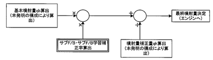
- a correction amount corresponding to the difference between the heat generation amount and the ideal heat generation amount is fed back to the fuel injection amount so that the heat generation amount matches the ideal heat generation amount at a predetermined excess air ratio. did.
- FIG. 3 is a flowchart of a control routine executed by the ECU 50 in order to realize the above-described operation. This control routine is executed every cycle, for example.
- the in-cylinder fresh air amount KL and the EGR rate introduced into the cylinder are calculated (step 100).
- FIG. 4 is a diagram showing the relationship between the combustion mass ratio change rate and the EGR rate for each engine speed NE.
- the ECU 50 stores a relationship map shown in FIG. 4 in advance.
- the ECU 50 calculates the engine speed NE from the signal CA of the crank angle sensor 18. Further, the ECU 50 calculates a combustion mass ratio change rate (combustion speed) from the combustion pressure detected by the in-cylinder pressure sensor 16 synchronized with the crank angle.
- the ECU 50 acquires an EGR rate (internal EGR + external EGR) corresponding to the engine speed NE and the combustion mass ratio change rate from the relationship map shown in FIG. Further, the ECU 50 calculates the total amount of fresh air and EGR gas from the compression pressure in the compression stroke, and calculates the in-cylinder fresh air amount KL from the total amount and the EGR rate.
- EGR rate internal EGR + external EGR
- the basic injection amount qb is calculated based on the engine speed NE, the in-cylinder fresh air amount KL, and the target excess air ratio (step 110).
- the cumulative heat generation amount after the start of combustion is calculated for each crank angle (step 120).
- the accumulated calorific value is the cylinder pressure P ( ⁇ 1 ) and cylinder volume V ( ⁇ 1 ) at the crank angle ⁇ 1 before combustion, and the cylinder pressure P ( ⁇ 2 ) and cylinder volume at the crank angle ⁇ 2 after starting combustion. It is calculated from the equation (1) based on V ( ⁇ 2 ), an experimentally determined constant ⁇ A , and a specific heat ratio ⁇ .
- the formula (1) is described in detail in Japanese Patent Application Laid-Open No. 2006-144463. Therefore, the description thereof is omitted in the description of the present embodiment.
- the calorific value detected after the end of combustion is greatly affected by an output error due to a cooling loss and distortion inside the sensor due to heat received by the in-cylinder pressure sensor 16.
- the value of the in-cylinder volume V becomes large, so that there is a possibility that the heat generation amount may not be accurately detected due to noise or the like.
- the maximum value within the period until the exhaust valve is opened in the cumulative heat generation amount calculated by the equation (1) is determined as the actual heat generation amount Qd.
- the timing for opening the exhaust valve is calculated from the signal CA of the crank angle sensor 18. According to such a configuration, the actual calorific value Qd can be accurately detected without affecting the above-described problem.
- step 120 it is determined whether or not misfiring will occur by comparing the actual calorific value Qd with the threshold value ⁇ (step 130).
- the ECU 50 stores a threshold value ⁇ by which an amount of generated heat that does not cause misfire is determined by experiments or the like. When the actual calorific value Qd is larger than the threshold value ⁇ , it is determined that no misfire occurs.
- injection amount feedback control based on the heat generation amount described in detail in steps 150 to 170 is started (step 140).
- the injection amount correction according to the difference between the actual heat generation amount Qd and the ideal heat generation amount Qt so that the actual heat generation amount Qd matches the target heat generation amount (ideal heat generation amount Qt described later).
- the amount is corrected to increase or decrease to the basic injection amount qb.
- an ideal heating value Qt at the time of previous combustion is calculated (step 150). Specifically, it is calculated how much heat is generated if an appropriate injection amount is injected in the previous cycle in which combustion has already been completed.
- the ECU 50 stores, for each target excess air ratio, a map that defines an ideal heat generation amount Qt according to the engine speed NE and the in-cylinder fresh air amount KL.
- the ideal heat generation amount Qt tends to increase linearly as the in-cylinder fresh air amount KL increases.
- the ECU 50 acquires an ideal heat generation amount Qt corresponding to the engine speed NE and the in-cylinder fresh air amount KL in the previous cycle from the map.
- the injection amount correction amount qh is calculated based on the deviation between the ideal heat generation amount Qt and the actual heat generation amount Qd (step 160).
- the ECU 50 has an injection amount correction map that defines an injection amount correction amount qh that increases as a positive value as the actual heat generation amount Qd is smaller than the ideal heat generation amount Qt and increases as a negative value as the actual heat generation amount Qd is larger than the ideal heat generation amount Qt. It is remembered.
- the ECU 50 acquires an injection amount correction amount qh corresponding to the deviation between the ideal heat generation amount Qt and the actual heat generation amount Qd from the injection amount correction map.
- the final injection amount is calculated by adding the injection amount correction amount qh to the basic injection amount qb calculated in step 110 (step 170).
- the ECU 50 causes the injector 14 to inject fuel according to the final injection amount.
- the injection amount feedback control is performed so that the actual heat generation amount Qd matches the ideal heat generation amount Qt. Thereafter, this routine is terminated.
- step 130 If it is determined in step 130 that a misfire has occurred, the value of the injection amount correction amount qh is set to zero. Therefore, in step 170, the basic injection amount qb is calculated as the final injection amount.
- the injection amount correction according to the difference between the actual heat generation amount Qd and the ideal heat generation amount Qt so that the actual heat generation amount Qd matches the ideal heat generation amount Qt in the stoichiometry.
- the quantity qh can be fed back to the basic injection quantity qb.
- the EGR rate is calculated by the processing of step 100, but the method of calculating the EGR rate is not limited to this.
- the external EGR rate is acquired from a map that defines the estimated value of the external EGR rate according to the output values of the air flow meter 24, the intake pressure sensor 30, and the throttle opening sensor 27, and the valve overlap amount is calculated. It is good also as acquiring an internal EGR rate from the map which defined the estimated value of the internal EGR rate according to a setting value. This point is the same in the following embodiments.
- the cumulative heat generation amount is calculated based on Equation (1), but the method of calculating the cumulative heat generation amount is not limited to this. For example, it is good also as calculating in step 120 based on following Formula (2). This point is the same in the following embodiments.
- FIG. 5 is a diagram showing an outline of sub-feedback control.
- the injection amount correction amount qh calculated in step 160 is further corrected so that the output of the sub O2 sensor 42 attached downstream of the catalyst 34 becomes a stoichiometric output. This point is the same in the following embodiments.
- the in-cylinder pressure sensor 16 corresponds to the “in-cylinder pressure sensor” in the first invention.
- the ECU 50 executes the process of step 100, so that the “in-cylinder pressure fresh air amount calculating means” in the first invention executes the process of step 120.
- the “actual heat generation amount calculation means” in step 1 executes the process of step 150
- the “target heat generation amount calculation means” in the first aspect of the invention executes the processing of steps 160 to 170.
- the “feedback means” in the first aspect of the invention is realized.
- the actual calorific value Qd calculated in step 120 is the “actual calorific value” in the first and second inventions
- the ideal calorific value Qt calculated in step 150 is the above-mentioned actual calorific value Qt. Each corresponds to the “target heat generation amount” in the first invention.
- FIG. 2 System Configuration of Embodiment 2
- FIG. 3 and 8 System Configuration of Embodiment 2
- the system of the present embodiment can be realized by causing the ECU 50 to execute the routines of FIGS. 3 and 8 described later in the configuration shown in FIG.
- a rich request or a lean request is made in order to keep drivability, emission, etc. suitably, and operation in the rich region or the lean region may be required temporarily.
- FIG. 6 is a diagram showing experimental results obtained by examining the relationship between the excess air ratio ⁇ and the heat generation for each operating condition.
- the calorific value tends to increase as the excess air ratio ⁇ becomes richer than stoichiometric under the same operating conditions, and decrease as it becomes leaner.
- the amount of heat generation tends to increase as the air-fuel ratio becomes close to 11, as the fuel becomes richer.
- the practical range of air-fuel ratio control is about 12 to 18.
- the calorific value varies greatly depending on the operating conditions such as the engine speed NE and the injection amount per unit time (FIG. 6). Therefore, if the ideal heat generation amount Qt is corrected using the relationship shown in FIG. 6 as it is, it is necessary to adapt the correction amount for each operating condition. Moreover, the subject that the ROM capacity of ECU50 is also required arises.
- FIG. 7 is a graph showing the relationship between the excess air ratio ⁇ and the heat generation ratio (heat generation amount other than stoichiometry / heat generation amount at stoichiometry) under the same operating conditions as in FIG.
- the calorific value ratio is expressed by a quadratic function of the excess air ratio ⁇ . As shown in FIG. 7, the calorific value ratio corresponding to the excess air ratio ⁇ is uniquely determined regardless of the operating conditions.
- the calorific value ratio tends to increase as the excess air ratio ⁇ becomes richer than stoichiometric, and decreases as it becomes leaner.
- the ideal heat generation amount Qt is corrected based on the relationship between the excess air ratio ⁇ and the heat generation amount ratio shown in FIG.
- FIG. 8 is a flowchart of a subroutine executed by the ECU 50 in order to realize the above function.
- This routine is a subroutine executed in place of the processing of step 150 in FIG.
- the control routine of the present embodiment is the same as the routine shown in FIG. 3 except that the processing in step 150 in FIG. 3 is replaced with the subroutine in FIG.
- the description of the same steps as those shown in FIG. 3 is omitted or simplified.
- an ideal heat generation amount Qt at the previous combustion is calculated (step 200). Specifically, it is calculated how much heat is generated if an appropriate injection amount is injected in the previous cycle in which combustion has already been completed.
- the ECU 50 stores, for each target excess air ratio, a map that defines an ideal heat generation amount Qt according to the engine speed NE and the in-cylinder fresh air amount KL.
- the ideal heat generation amount Qt increases linearly as the in-cylinder fresh air amount KL increases.
- the ECU 50 acquires an ideal heat generation amount Qt corresponding to the engine speed NE and the in-cylinder fresh air amount KL in the previous cycle from the map.
- the ideal heat generation amount Qt is corrected based on the target excess air ratio (step 210).
- step 210 After the process of step 210, the process after step 160 of FIG. 3 is executed based on the new ideal heat generation amount Qt.
- the ideal heat generation amount Qt can be corrected based on the relationship between the target excess air ratio and the heat generation amount ratio. Therefore, according to the system of the present embodiment, it is possible to improve the accuracy of the injection amount control in accordance with the catalyst purification window. Further, according to the relationship between the target excess air ratio and the calorific value ratio, it is possible to realize a highly robust system that is not affected by the fuel properties and operating conditions. Furthermore, according to the system of the present embodiment, the ideal heat generation amount Qt can be corrected based on the single relationship map shown in FIG. it can. In addition, the ROM capacity of the ECU 50 can be greatly reduced.
- the “target air excess ratio setting means” and the “correction means” in the third aspect of the present invention are realized by the ECU 50 executing the processing of step 210 described above. .
- Embodiment 3 FIG. [System Configuration of Embodiment 3] Next, a third embodiment of the present invention will be described with reference to FIGS.
- the system of this embodiment can be realized by causing the ECU 50 to execute the routines of FIGS. 3 and 10 described later in the configuration shown in FIG.
- ignition timing control for advancing / retarding the ignition timing of the spark plug 12 from MBT (Minimum Advance for Best Torque) according to the driving request is also performed. Is called.
- the total calorific value decreases when the ignition timing is advanced from MBT. Further, when the ignition timing is retarded from MBT, the total heat generation amount increases. For this reason, the amount of heat generated at the combustion time when the combustion ratio is 50% (hereinafter simply referred to as the 50% combustion point) becomes higher on the retard side and lower on the advance side.
- the heat generation amount is affected by the ignition timing in this way is considered to be because the amount of HC afterburning varies depending on the position of the center of gravity of combustion.
- the calorific value varies greatly depending on the operating conditions such as the engine speed NE and the in-cylinder fresh air amount KL. Therefore, if the ideal heat generation amount Qt is to be corrected for each operating condition, it is necessary to adapt the correction amount for each operating condition. Moreover, the subject that the ROM capacity of ECU50 is also required arises.
- FIG. 9 is a diagram showing the relationship between the deviation of the 50% combustion point other than MBT from ATDC8CA and the heat generation amount ratio (heat generation amount of 50% combustion point other than MBT / heat generation amount of MBT 50% combustion point). .
- the relationship between the deviation and the heat generation ratio is uniquely determined regardless of the operating conditions.
- the calorific value ratio tends to increase as the angle is retarded from the MBT and to decrease as the angle is advanced from the MBT.
- the ideal heat generation amount Qt is corrected based on the relationship between the deviation from the ATDC8CA of the 50% combustion point shown in FIG. 9 and the heat generation amount ratio.
- FIG. 10 is a flowchart of a subroutine executed by the ECU 50 in order to realize the above function.
- This routine is a subroutine executed in place of the processing of step 150 in FIG.
- the control routine of this embodiment is the same as the routine shown in FIGS. 3 and 8 except that step 230 is added after the process of step 210 of FIG.
- the same steps as those shown in FIGS. 3 and 8 are denoted by the same reference numerals, and the description thereof is omitted or simplified.
- the ideal heat generation amount Qt is corrected based on the relationship between the deviation from the ATDC 8CA of the 50% combustion point shown in FIG. 9 and the heat generation amount ratio (step 230).
- the ECU 50 stores in advance a map that defines a target value of a 50% combustion point (hereinafter referred to as a target 50% combustion point) in accordance with an operation request (request regarding fuel consumption, emission, etc.) in another routine.
- a 50% combustion point corresponding to the operating condition is acquired from this map and set as a target 50% combustion point.
- a deviation between the MBT 50% combustion point and the target 50% combustion point is calculated.
- the ECU 50 stores in advance the relationship map shown in FIG. A calorific value ratio corresponding to the deviation is acquired from this relationship map.
- the ECU 50 multiplies the acquired heat generation amount ratio as a correction coefficient by the ideal heat generation amount Qt to obtain a new ideal heat generation amount Qt.
- step 230 After the processing of step 230, the processing after step 160 in FIG. 3 is executed based on the new ideal heat generation amount Qt.
- the ideal heat generation amount Qt can be corrected based on the relationship between the deviation of the target 50% combustion point from the ATDC 8CA and the heat generation amount ratio. Therefore, according to the system of the present embodiment, it is possible to improve the accuracy of the injection amount control in accordance with the catalyst purification window. Further, according to the relationship between the deviation of the target 50% combustion point from the ATDC8CA and the calorific value ratio, a highly robust system that is not affected by the fuel properties and the operating conditions can be realized. Furthermore, according to the system of the present embodiment, the ideal heat generation amount Qt can be corrected with higher accuracy and adjusted to the catalyst purification window by further considering the influence factor on the heat generation amount as compared with the above-described embodiment. Appropriate injection amount control can be realized.
- the ideal heat generation amount Qt can be corrected based on the single relationship map shown in FIG. 9, so that the number of adaptation man-hours corresponding to operating conditions can be greatly reduced. it can. Furthermore, the ROM capacity of the ECU 50 can be greatly reduced.
- the correction of the ideal heat generation amount Qt in step 230 is used together with the correction of the ideal heat generation amount Qt in step 210.
- the present invention is not limited to this. Only the process of step 230 may be performed without performing the process of step 210. This also applies to the following embodiments.
- the relationship map shown in FIG. 9 is determined based on the 50% combustion point, but the reference of the combustion point is not limited to this. It is good also as a combustion point in arbitrary combustion ratios.
- the 50% combustion point in MBT is ATDC8CA, but this value varies depending on the system and is not limited to ATDC8CA.
- the “target combustion point setting means” and the “correction means” in the fifth aspect of the present invention are realized by the ECU 50 executing the processing of step 230 described above.
- Embodiment 4 FIG. [System Configuration of Embodiment 4] Next, a fourth embodiment of the present invention will be described with reference to FIGS.
- the system of the present embodiment can be realized by causing the ECU 50 to execute the routines of FIGS. 3 and 11 described later in the configuration shown in FIG.
- the ignition timing control is performed by determining the target 50% combustion point according to the operation request.
- a control error occurs in the process of ignition timing control. If a control error occurs, the amount of heat generation also changes.
- the calorific value varies greatly depending on the operating conditions such as the engine speed NE and the in-cylinder fresh air amount KL. Therefore, if the actual calorific value Qd is to be corrected for each operating condition, the correction amount needs to be adapted for each operating condition. Moreover, the subject that the ROM capacity of ECU50 is also required arises.
- FIG. 11 is a diagram showing the relationship between the deviation from the ATDC8CA of the 50% combustion point other than MBT and the heat generation amount ratio (heat generation amount of 50% combustion point other than MBT / heat generation amount of MBT 50% combustion point). .
- the relationship between the deviation and the heat generation ratio is uniquely determined regardless of the operating conditions.
- the calorific value ratio tends to increase as the angle is retarded from the MBT and to decrease as the angle is advanced from the MBT.
- a in FIG. 11 indicates a target 50% combustion point.
- B shown in FIG. 11 shows an actual 50% combustion point (hereinafter referred to as an actual 50% combustion point), which is a result of performing the ignition timing control according to the target 50% combustion point.
- an actual 50% combustion point hereinafter referred to as an actual 50% combustion point
- the actual heating value Qd is based on the difference between the heating value ratio of the target 50% combustion point with respect to the MBT 50% combustion point and the heating value ratio of the actual 50% combustion point with respect to the MBT 50% combustion point. It was decided to correct.
- FIG. 12 is a flowchart of a subroutine executed by the ECU 50 in order to realize the above function.
- This routine is a subroutine executed in place of the processing of step 150 in FIG.
- the control routine of this embodiment is the same as the routine shown in FIGS. 3 and 10 except that step 260 is added after the process of step 230 of FIG.
- step 260 is added after the process of step 230 of FIG.
- the actual heat generation amount Qd is corrected based on the relationship between the deviation from the target 50% combustion point and the actual 50% combustion point shown in FIG. (Step 260). This will be specifically described. First, a crank angle that is half of the total calorific value in the previous cycle is calculated as an actual 50% combustion point. Then, a deviation between the MBT 50% combustion point and the actual 50% combustion point is calculated.
- the ECU 50 stores the relationship map shown in FIG. 11 described above in advance. A calorific value ratio corresponding to the deviation (hereinafter referred to as an actual 50% combustion point calorific value ratio) is acquired from this relationship map.
- the ECU 50 stores in advance a map that defines a target 50% combustion point according to an operation request in another routine. From this map, a target 50% combustion point corresponding to the operating condition of the previous cycle is set. Next, the deviation between the MBT 50% combustion point and the target 50% combustion point is calculated. Thereafter, a heat value ratio corresponding to the deviation (hereinafter referred to as a target 50% combustion point heat value ratio) is acquired from the relationship map shown in FIG.
- the ECU 50 multiplies the actual heat generation amount Qd by using the calculated heat generation amount ratio as a correction coefficient to obtain a new actual heat generation amount Qd.
- step 260 After the process of step 260, the process after step 160 of FIG. 3 is executed based on the new actual heat generation amount Qd.
- the actual calorific value Qd can be corrected based on the relationship between the deviation of the target 50% combustion point and the actual 50% combustion point from the ATDC 8CA and the calorific value ratio. it can. Therefore, according to the system of the present embodiment, it is possible to improve the accuracy of the injection amount control in accordance with the catalyst purification window. Further, according to the relationship with the calorific value ratio, it is possible to realize a highly robust system that is not affected by fuel properties and operating conditions. Furthermore, according to the system of the present embodiment, the actual heat generation amount Qd can be accurately corrected according to the amount of change in the heat generation amount caused by the control error, and appropriate injection amount control in accordance with the catalyst purification window can be realized. it can.
- the actual calorific value Qd can be corrected based on the single relation map shown in FIG. 12, so that the number of man-hours for adaptation according to the operating conditions can be greatly reduced. it can. Furthermore, the ROM capacity of the ECU 50 can be greatly reduced.
- the correction of the actual heat generation amount Qd in step 260 is used together with the correction of the ideal heat generation amount Qt in steps 210 and 230.
- the present invention is not limited to this. Absent. It is good also as combining only the process of step 260, or the process of each step. This point is the same in the following embodiments.
- the ECU 50 executes the processing of step 260 to thereby perform the “target combustion point setting means”, “actual combustion point calculation means”, and “actual heat generation amount” in the eighth invention. "Correction means” is realized respectively.
- Embodiment 5 FIG. [System Configuration of Embodiment 5] Next, a fifth embodiment of the present invention will be described with reference to FIGS.
- a water temperature sensor 44 that detects the water temperature of the engine 10 is added to the configuration of FIG. 1 described above.
- the water temperature sensor 44 is connected to the input unit of the ECU 50.
- the system of this embodiment is realizable by making ECU50 implement the routine of FIG.3 and FIG.14 mentioned later.
- the calorific value also changes depending on the difference in cooling loss due to the water temperature (cylinder wall temperature).
- FIG. 13 is a diagram showing the relationship between the water temperature and the calorific value correction coefficient.
- the calorific value correction coefficient in a completely warm-up state (for example, 80 ° C.) is 1. Further, the calorific value correction coefficient is not changed depending on the operating conditions, but is determined only by the water temperature. Further, the heat generation amount correction coefficient tends to be smaller as the water temperature is lower than the complete warm-up state, and to be greater as the water temperature is higher than the complete warm-up state.
- the ideal heat generation amount Qt is corrected based on the relationship between the water temperature and the heat generation amount correction coefficient shown in FIG. Specifically, the ideal heating value Qt is corrected to decrease as the water temperature decreases.
- FIG. 14 is a flowchart of a subroutine executed by the ECU 50 in order to realize the above function.
- This routine is a subroutine executed in place of the processing of step 150 in FIG.
- the control routine of this embodiment is the same as the routine shown in FIGS. 3 and 12 except that step 220 is added after the process of step 210 of FIG.
- step 220 is added after the process of step 210 of FIG.
- the same steps as those shown in FIGS. 3 and 12 are denoted by the same reference numerals, and the description thereof is omitted or simplified.
- the ideal heat generation amount Qt is corrected based on the relationship between the water temperature and the heat generation amount correction coefficient shown in FIG. 13 (step 220).
- the water temperature is detected by the water temperature sensor 44.
- the ECU 50 stores in advance the relationship map shown in FIG. From this relationship map, a heat generation amount correction coefficient corresponding to the water temperature is acquired.
- the ECU 50 multiplies the acquired heat generation amount correction coefficient by the ideal heat generation amount Qt to obtain a new ideal heat generation amount Qt.
- step 260 After the process of step 260, the process after step 160 of FIG. 3 is executed based on the new ideal heat generation amount Qt.
- the ideal heat generation amount Qt can be corrected based on the relationship between the water temperature and the heat generation amount correction coefficient. Therefore, according to the system of the present embodiment, it is possible to improve the accuracy of the injection amount control in accordance with the catalyst purification window. Moreover, since the calorific value correction coefficient is determined by using only the water temperature as a parameter, it is possible to significantly reduce the number of man-hours for adaptation according to the operating conditions. Furthermore, the ROM capacity of the ECU 50 can be greatly reduced.
- the correction of the ideal heat generation amount Qt in step 220 is used in combination with the correction of the ideal heat generation amount Qt in steps 210 and 230 and the correction of the actual heat generation amount Qd in step 260.
- it is not limited to this. It is good also as combining only the process of step 220, or the process of each step. This point is the same in the following embodiments.
- the water temperature sensor 44 corresponds to the “water temperature detecting means” in the fourth invention.
- the “correction means” in the fourth aspect of the present invention is realized by the ECU 50 executing the processing of step 220 described above.
- Embodiment 6 FIG. [System Configuration of Embodiment 6] Next, a sixth embodiment of the present invention will be described with reference to FIGS.
- the system of the present embodiment can be realized by causing the ECU 50 to execute the routines of FIGS. 3 and 15 described later in the configuration shown in FIG.
- FIG. 15 is a flowchart of a subroutine executed by the ECU 50 in order to realize the above-described function.
- This routine is a subroutine executed in place of the processing of step 150 in FIG.
- the control routine of this embodiment is the same as the routine shown in FIGS. 3 and 14 except that step 240 is added after the process of step 230 of FIG.
- step 240 is added after the process of step 230 of FIG.
- the same steps as those shown in FIGS. 3 and 14 are denoted by the same reference numerals, and description thereof is omitted or simplified.
- step 240 the ideal heat generation amount Qt is corrected by the fuel property (step 240).
- the process in step 240 will be described in three stages.
- FIG. 16 is a graph showing the relationship between the excess air ratio ⁇ and the stoichiometric ratio of the calorific value / injection amount.
- the ECU 50 stores a relationship map shown in FIG. As described above, the heat generation amount / injection amount (heat generation efficiency) tends to decrease as the richer side (FIG. 21). Further, the stoichiometric ratio is not affected by the operating conditions. From this relationship map, the stoichiometric ratio of the heat generation amount / injection amount corresponding to the target excess air ratio is acquired. The calorific value is corrected by multiplying the calorific value by the reciprocal of the acquired stoichiometric ratio. By this process, the change in the lower heating value can be corrected in advance.
- FIG. 17 is a diagram showing the relationship between the injection time / heat generation amount and the ethanol concentration.
- the ECU 50 stores a relationship map shown in FIG.
- the injection time corresponds to the injection amount and is calculated from the control value of the injector 14. From this relationship map, the ethanol concentration corresponding to the calorific value / injection time is acquired based on the calorific value corrected in the first stage. In addition, it is desirable to be based on the heat generation amount and the injection amount in the past predetermined number of cycles.
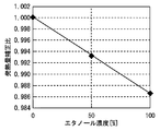
- FIG. 18 is a diagram showing the relationship between the ethanol concentration and the calorific value correction ratio.
- the calorific value correction ratio corresponds to the calorific value ratio at stoichiometry in FIG. Since FIG. 18 has the same tendency as FIG. 2 described above, description thereof is omitted.
- the ECU 50 stores a relationship map shown in FIG. From this relationship map, the calorific value correction value corresponding to the ethanol concentration acquired in the second stage is acquired. Thereafter, the ECU 50 multiplies the ideal heat generation amount Qt by the heat generation amount correction value to obtain a new ideal heat generation amount Qt.
- step 260 After the process of step 260, the process after step 160 of FIG. 3 is executed based on the new ideal heat generation amount Qt.
- the fuel property is judged more accurately by correcting the change in the lower calorific value in accordance with the change in the target excess air ratio and determining the fuel property.
- the correction of the ideal heat generation amount Qt in step 240 is used in combination with the correction of the ideal heat generation amount Qt in steps 210 to 230 and the correction of the actual heat generation amount Qd in step 260.
- it is not limited to this. It is good also as combining only the process of step 240, or the process of each step. This point is the same in the following embodiments.
- the “alcohol concentration acquisition means” and the “correction means” according to the sixth aspect of the present invention are realized by the ECU 50 executing the process of step 240 described above.
- Embodiment 7 FIG. [System Configuration of Embodiment 7] Next, a sixth embodiment of the present invention will be described with reference to FIGS.
- the system of the present embodiment can be realized by causing the ECU 50 to execute the routines of FIGS. 3 and 20 described later in the configuration shown in FIG.
- the calorific value also changes when the specific heat ratio increases and the cooling loss decreases due to the increase in EGR gas.
- FIG. 19 is a diagram showing the relationship between the EGR rate and the calorific value change ratio.
- the heating value change increasing rate tends to increase linearly as the EGR rate increases regardless of the operating conditions.
- the calorific value increases by 4% for an EGR rate of 20%. Therefore, in the system of this embodiment, the ideal heat generation amount Qt is corrected based on the relationship between the EGR rate and the heat generation amount change ratio shown in FIG. Specifically, the ideal heating value Qt is increased and corrected as the EGR rate is higher.
- FIG. 20 is a flowchart of a subroutine executed by the ECU 50 in order to realize the above function.
- This routine is a subroutine executed in place of the processing of step 150 in FIG.
- the control routine of this embodiment is the same as the routine shown in FIGS. 3 and 15 except that step 250 is added after the process of step 240 of FIG.
- step 250 is added after the process of step 240 of FIG.
- the same steps as those shown in FIGS. 3 and 15 are denoted by the same reference numerals, and the description thereof is omitted or simplified.
- the ideal heat generation amount Qt is corrected based on the relationship between the EGR rate and the heat generation amount change ratio shown in FIG. 19 (step 250).
- the ECU 50 stores in advance the relationship map shown in FIG. In step 210, a heat generation amount change ratio corresponding to the EGR rate calculated in step 100 is acquired from this relationship map.
- the ECU 50 multiplies the acquired heat generation amount change ratio by the ideal heat generation amount Qt to obtain a new ideal heat generation amount Qt.
- step 260 After the process of step 260, the process after step 160 of FIG. 3 is executed based on the new ideal heat generation amount Qt.
- the ideal heat generation amount Qt can be corrected based on the relationship between the EGR rate and the injection amount change ratio. Since the calorific value change ratio is determined using only the EGR rate as a parameter, a highly robust system that is not affected by the operating conditions can be realized. Further, according to the system of the present embodiment, it is possible to realize appropriate injection amount control in accordance with the catalyst purification window by assuming all influencing factors on the calorific value.
- the correction of the ideal heat generation amount Qt in step 250 is used in combination with the correction of the ideal heat generation amount Qt in steps 210 to 240 and the correction of the actual heat generation amount Qd in step 260.
- it is not limited to this. It is good also as combining only the process of step 250, or the process of each step. This point is the same in the following embodiments.
- the ECU 50 executes the process of step 100, so that the “EGR rate acquisition means” in the seventh invention executes the process of step 250.
- the “correction means” in the seventh aspect of the invention is realized.
Abstract
Description
筒内圧を検出する筒内圧センサと、
前記筒内圧センサにより検出された筒内圧に基づいて筒内新気量を算出する筒内新気量算出手段と、
前記筒内圧センサにより検出された筒内圧に基づいて実発熱量を算出する実発熱量算出手段と、
前記筒内新気量算出手段により算出された筒内新気量から所定の空気過剰率における目標発熱量を算出する目標発熱量算出手段と、
前記実発熱量算出手段により算出された実発熱量が前記目標発熱量と一致するように、該実発熱量と前記目標発熱量との比較値を燃料噴射量にフィードバックするフィードバック手段と、を備えることを特徴とする。 In order to achieve the above object, a first invention is a control device for an internal combustion engine,
An in-cylinder pressure sensor for detecting the in-cylinder pressure;
In-cylinder fresh air amount calculating means for calculating the in-cylinder fresh air amount based on the in-cylinder pressure detected by the in-cylinder pressure sensor;
Actual calorific value calculation means for calculating an actual calorific value based on the in-cylinder pressure detected by the in-cylinder pressure sensor;
Target heat generation amount calculation means for calculating a target heat generation amount at a predetermined excess air ratio from the in-cylinder fresh air amount calculated by the in-cylinder fresh air amount calculation means;
Feedback means for feeding back a comparison value between the actual heat generation amount and the target heat generation amount to the fuel injection amount so that the actual heat generation amount calculated by the actual heat generation amount calculation unit coincides with the target heat generation amount. It is characterized by that.
前記実発熱量は、燃焼開始から排気バルブが開くまでの期間内における最大値であることを特徴とする。 The second invention is the first invention, wherein
The actual heat generation amount is a maximum value within a period from the start of combustion to the opening of the exhaust valve.
運転要求に基づいて目標空気過剰率を設定する目標空気過剰率設定手段と、
前記目標発熱量を、前記所定の空気過剰率における発熱量と前記目標空気過剰率における発熱量との発熱量比に基づいて補正する補正手段と、を備えることを特徴とする。 The third invention is the first or second invention, wherein
A target excess air ratio setting means for setting a target excess air ratio based on the operation request;
And a correction unit that corrects the target heat generation amount based on a heat generation ratio between a heat generation amount at the predetermined excess air ratio and a heat generation amount at the target air excess ratio.
水温を検出する水温検出手段と、
前記目標発熱量を、前記水温検出手段により検出された水温が低いほど減少補正する補正手段と、を備えることを特徴とする。 According to a fourth invention, in any one of the first to third inventions,
Water temperature detecting means for detecting the water temperature;
And a correction unit that corrects a decrease in the target heat generation amount as the water temperature detected by the water temperature detection unit decreases.
点火時期に基づいて燃焼割合が所定割合となる目標燃焼点を設定する目標燃焼点設定手段と、
前記目標発熱量を、MBTでの燃焼割合が前記所定割合となる燃焼点(以下、MBT燃焼点と記す。)における発熱量と、前記目標燃焼点における発熱量との発熱量比に基づいて補正する補正手段と、を備えることを特徴とする。 According to a fifth invention, in any one of the first to fourth inventions,
Target combustion point setting means for setting a target combustion point at which the combustion ratio becomes a predetermined ratio based on the ignition timing;
The target calorific value is corrected based on a calorific value ratio between a calorific value at a combustion point (hereinafter referred to as an MBT combustion point) at which the combustion rate in MBT becomes the predetermined rate and a calorific value at the target combustion point. And a correcting means for performing.
前記実発熱量算出手段により算出された実発熱量を得るために要した燃料噴射量と、該実発熱量とに基づいて燃料中のアルコール濃度を取得するアルコール濃度取得手段と、
前記目標発熱量を、前記アルコール濃度取得手段により取得されたアルコール濃度が高いほど減少補正する補正手段と、を備えることを特徴とする。 According to a sixth invention, in any one of the first to fifth inventions,
Alcohol concentration acquisition means for acquiring the alcohol concentration in the fuel based on the fuel injection amount required to obtain the actual heat generation amount calculated by the actual heat generation amount calculation means, and the actual heat generation amount;
Correction means for correcting the decrease in the target calorific value as the alcohol concentration acquired by the alcohol concentration acquisition means increases.
EGR率を取得するEGR率取得手段と、
前記目標発熱量を、前記EGR率取得手段により取得されたEGR率が高いほど増大補正する補正手段と、を備えることを特徴とする。 According to a seventh invention, in any one of the first to sixth inventions,
EGR rate acquisition means for acquiring an EGR rate;
Correction means for correcting the target heat generation amount to increase as the EGR rate acquired by the EGR rate acquisition unit increases.
点火時期に基づいて燃焼割合が前記所定割合となる目標燃焼点を設定する目標燃焼点設定手段と、
前記点火時期における燃焼割合が前記所定割合となる実燃焼点を算出する実燃焼点算出手段と、
前記実発熱量を、MBT燃焼点に対する前記目標燃焼点の発熱量比と、MBT燃焼点に対する前記実燃焼点の発熱量比との差に基づいて補正する実発熱量補正手段と、を備えることを特徴とする。 According to an eighth invention, in any one of the first to seventh inventions,
Target combustion point setting means for setting a target combustion point at which the combustion ratio becomes the predetermined ratio based on the ignition timing;
An actual combustion point calculating means for calculating an actual combustion point at which the combustion ratio at the ignition timing becomes the predetermined ratio;
An actual heating value correction means for correcting the actual heating value based on a difference between a heating value ratio of the target combustion point with respect to the MBT combustion point and a heating value ratio of the actual combustion point with respect to the MBT combustion point; It is characterized by.
Qt 理想発熱量
qb 基本噴射量
qh 噴射量補正量
α 閾値
λ 空気過剰率
10 エンジン
12 スパークプラグ
14 インジェクタ
16 筒内圧センサ
18 クランク角度センサ
24 エアフローメータ
26 スロットルバルブ
27 スロットル開度センサ
30 吸気圧センサ
34 触媒
36 EGR通路
42 サブO2センサ
44 水温センサ
50 ECU(Electronic Control Unit) Qd Actual heat generation amount Qt Ideal heat generation amount qb Basic injection amount qh Injection amount correction amount α Threshold value λ Air
[実施の形態1のシステム構成]
図1は、本発明の実施の形態1のシステム構成を説明するための概略構成図である。図1に示すシステムは、内燃機関(以下、単にエンジンという。)10を備えている。図1に示すエンジン10は、スパークプラグ12を備えた火花点火式の4ストロークレシプロエンジンである。また、エンジン10は、筒内に燃料を直接噴射するインジェクタ14を備えた筒内直噴エンジンでもある。燃料には、ガソリンやアルコール(例えば、エタノール)混合燃料が用いられる。
[System Configuration of Embodiment 1]
FIG. 1 is a schematic configuration diagram for explaining a system configuration according to the first embodiment of the present invention. The system shown in FIG. 1 includes an internal combustion engine (hereinafter simply referred to as an engine) 10. An
上述したシステム構成においては、エミッション等を好適に保つため、噴射量フィードバック制御(PID制御)を実施することが望まれる。ところが、上述したシステムでは、コスト低減のため、触媒34の上流に空燃比センサが取り付けられていない。そこで、例えば日本特開2006-144643号公報に開示されているように、空燃比センサを代替するために、筒内圧センサの出力値から検出される発熱量から空燃比を算出し、空燃比を理論空燃比に一致させるように、空燃比と理論空燃比との差に応じた補正量を燃料噴射量にフィードバックすることが考えられる。 [Characteristic Control in Embodiment 1]
In the above-described system configuration, it is desired to perform injection amount feedback control (PID control) in order to keep emissions and the like appropriately. However, in the system described above, an air-fuel ratio sensor is not attached upstream of the
図3は、上述の動作を実現するために、ECU50が実行する制御ルーチンのフローチャートである。この制御ルーチンは、例えば1サイクル毎に実行される。図3に示すルーチンでは、まず、筒内に導入された筒内新気量KLとEGR率とが算出される(ステップ100)。図4は、燃焼質量割合変化率とEGR率との関係をエンジン回転数NE毎に示した図である。ECU50には、図4に示す関係マップが予め記憶されている。ECU50は、クランク角度センサ18の信号CAからエンジン回転数NEを算出する。また、ECU50は、クランク角に同期した筒内圧センサ16によって検出された燃焼圧から燃焼質量割合変化率(燃焼速度)を算出する。そして、ECU50は、図4に示す関係マップからエンジン回転数NEと燃焼質量割合変化率とに応じたEGR率(内部EGR+外部EGR)を取得する。さらに、ECU50は、圧縮行程における圧縮圧から新気とEGRガスとの総量を算出し、この総量とEGR率とから筒内新気量KLを算出する。 (Control routine)
FIG. 3 is a flowchart of a control routine executed by the

[実施の形態2のシステム構成]
次に、図6~図8を参照して本発明の実施の形態2について説明する。本実施形態のシステムは図1に示す構成において、ECU50に後述する図3及び図8のルーチンを実施させることで実現することができる。 Embodiment 2. FIG.
[System Configuration of Embodiment 2]
Next, a second embodiment of the present invention will be described with reference to FIGS. The system of the present embodiment can be realized by causing the
上述した実施の形態1では、燃料性状によらないで、実発熱量Qdをストイキ(空気過剰率λ=1)における理想発熱量Qtに一致させる噴射量フィードバック制御を実施している。ところで、エンジン10の制御においては、ドライバビリティやエミッション等を好適に保つためにリッチ要求やリーン要求がなされ、一時的にリッチ域やリーン域での運転が求められる場合もある。 [Characteristic Control in Embodiment 2]
In the first embodiment described above, the injection amount feedback control is performed to match the actual heat generation amount Qd with the ideal heat generation amount Qt at the stoichiometric (excess air ratio λ = 1) regardless of the fuel properties. By the way, in the control of the
図8は、上述の機能を実現するために、ECU50が実行するサブルーチンのフローチャートである。このルーチンは、図3のステップ150の処理に換えて実行されるサブルーチンである。換言すれば、本実施形態の制御ルーチンは、図3のステップ150の処理が、図8のサブルーチンに置き換えられている点を除き、図3に示すルーチンと同様である。以下、本実施形態の制御ルーチンのうち、図3に示すステップと同一のステップについては、その説明を省略または簡略する。 (Control routine)
FIG. 8 is a flowchart of a subroutine executed by the
[実施の形態3のシステム構成]
次に、図9~図10を参照して本発明の実施の形態3について説明する。本実施形態のシステムは図1に示す構成において、ECU50に後述する図3及び図10のルーチンを実施させることで実現することができる。 Embodiment 3 FIG.
[System Configuration of Embodiment 3]
Next, a third embodiment of the present invention will be described with reference to FIGS. The system of this embodiment can be realized by causing the
上述した実施の形態1では、燃料性状によらないで、実発熱量Qdをストイキ(空気過剰率λ=1)における理想発熱量Qtに一致させる噴射量フィードバック制御を実施している。ところで、エンジン10の制御においては、運転要求(燃費やエミッション等に関する要求)に応じて、スパークプラグ12の点火時期をMBT(Minimum Advance for Best Torque)から進角・遅角させる点火時期制御も行われる。 [Characteristic Control in Embodiment 3]
In the first embodiment described above, the injection amount feedback control is performed to match the actual heat generation amount Qd with the ideal heat generation amount Qt at the stoichiometric (excess air ratio λ = 1) regardless of the fuel properties. By the way, in the control of the
図10は、上述の機能を実現するために、ECU50が実行するサブルーチンのフローチャートである。このルーチンは、図3のステップ150の処理に換えて実行されるサブルーチンである。本実施形態の制御ルーチンは、図8のステップ210の処理後に、ステップ230が追加されている点を除き、図3及び図8に示すルーチンと同様である。以下、本実施形態の制御ルーチンのうち、図3及び図8に示すステップと同一のステップについては、同一の符号を付してその説明を省略または簡略する。 (Control routine)
FIG. 10 is a flowchart of a subroutine executed by the
[実施の形態4のシステム構成]
次に、図11~図12を参照して本発明の実施の形態4について説明する。本実施形態のシステムは図1に示す構成において、ECU50に後述する図3及び図11のルーチンを実施させることで実現することができる。 Embodiment 4 FIG.
[System Configuration of Embodiment 4]
Next, a fourth embodiment of the present invention will be described with reference to FIGS. The system of the present embodiment can be realized by causing the
上述した実施の形態3では、運転要求に応じた目標50%燃焼点を定めて点火時期制御が行われる。しかしながら、点火時期制御の過程においては制御誤差が生じる。制御誤差が生じれば発熱量も変化することとなる。噴射量フィードバック制御の精度を高めるためには、このような制御誤差による発熱量への影響に鑑み、発熱量の変化分に応じて実発熱量Qdを補正することが望ましい。 [Characteristic Control in Embodiment 4]
In the third embodiment described above, the ignition timing control is performed by determining the
図12は、上述の機能を実現するために、ECU50が実行するサブルーチンのフローチャートである。このルーチンは、図3のステップ150の処理に換えて実行されるサブルーチンである。本実施形態の制御ルーチンは、図10のステップ230の処理後に、ステップ260が追加されている点を除き、図3及び図10に示すルーチンと同様である。以下、本実施形態の制御ルーチンのうち、図3及び図10に示すステップと同一のステップについては、同一の符号を付してその説明を省略または簡略する。 (Control routine)
FIG. 12 is a flowchart of a subroutine executed by the
[実施の形態5のシステム構成]
次に、図13~図14を参照して本発明の実施の形態5について説明する。本実施形態のシステムには、上述した図1の構成に、エンジン10の水温を検出する水温センサ44が加えられている。水温センサ44は、ECU50の入力部に接続されている。そして、本実施形態のシステムは、ECU50に後述する図3及び図14のルーチンを実施させることで実現することができる。
[System Configuration of Embodiment 5]
Next, a fifth embodiment of the present invention will be described with reference to FIGS. In the system of the present embodiment, a
上述した実施の形態1では、燃料性状によらないで、実発熱量Qdをストイキ(空気過剰率λ=1)における理想発熱量Qtに一致させる噴射量フィードバック制御を実施している。ところで、発熱量は、水温(シリンダ壁温)による冷却損失の違いによっても変化する。噴射量フィードバック制御の精度を高めるためには、このような影響を鑑みて理想発熱量Qtを補正することが望ましい。 [Characteristic Control in Embodiment 5]
In the first embodiment described above, the injection amount feedback control is performed to match the actual heat generation amount Qd with the ideal heat generation amount Qt at the stoichiometric (excess air ratio λ = 1) regardless of the fuel properties. By the way, the calorific value also changes depending on the difference in cooling loss due to the water temperature (cylinder wall temperature). In order to improve the accuracy of the injection amount feedback control, it is desirable to correct the ideal heat generation amount Qt in view of such influence.
図14は、上述の機能を実現するために、ECU50が実行するサブルーチンのフローチャートである。このルーチンは、図3のステップ150の処理に換えて実行されるサブルーチンである。本実施形態の制御ルーチンは、図12のステップ210の処理後に、ステップ220が追加されている点を除き、図3及び図12に示すルーチンと同様である。以下、本実施形態の制御ルーチンのうち、図3及び図12に示すステップと同一のステップについては、同一の符号を付してその説明を省略または簡略する。 (Control routine)
FIG. 14 is a flowchart of a subroutine executed by the
[実施の形態6のシステム構成]
次に、図15~図18を参照して本発明の実施の形態6について説明する。本実施形態のシステムは図1に示す構成において、ECU50に後述する図3及び図15のルーチンを実施させることで実現することができる。 Embodiment 6 FIG.
[System Configuration of Embodiment 6]
Next, a sixth embodiment of the present invention will be described with reference to FIGS. The system of the present embodiment can be realized by causing the
上述した実施の形態1では、燃料性状が異なってもストイキにおける発熱量比の違いは僅かである点に着目して(図2)、実発熱量Qdをストイキにおける理想発熱量Qtに一致させる噴射量フィードバック制御を実施している。ここで、燃料性状による気化潜熱の違い等に起因する発熱量比の違いも踏まえて、理想発熱量Qtを補正できれば更に望ましい。そこで、本実施形態のシステムでは、燃料性状による発熱量比の違いに基づいて理想発熱量Qtを補正することとした。 [Characteristic Control in Embodiment 6]
In the first embodiment described above, paying attention to the fact that the difference in the calorific value ratio in stoichiometry is small even if the fuel properties are different (FIG. 2), the injection that matches the actual calorific value Qd with the ideal calorific value Qt in stoichiometry. Quantity feedback control is implemented. Here, it is more desirable if the ideal heat generation amount Qt can be corrected in consideration of the difference in heat generation amount ratio caused by the difference in latent heat of vaporization due to the fuel properties. Therefore, in the system of the present embodiment, the ideal heat generation amount Qt is corrected based on the difference in the heat generation amount ratio depending on the fuel properties.
図15は、上述の機能を実現するために、ECU50が実行するサブルーチンのフローチャートである。このルーチンは、図3のステップ150の処理に換えて実行されるサブルーチンである。本実施形態の制御ルーチンは、図14のステップ230の処理後に、ステップ240が追加されている点を除き、図3及び図14に示すルーチンと同様である。以下、本実施形態の制御ルーチンのうち、図3及び図14に示すステップと同一のステップについては、同一の符号を付してその説明を省略または簡略する。 (Control routine)
FIG. 15 is a flowchart of a subroutine executed by the
[実施の形態7のシステム構成]
次に、図19~図20を参照して本発明の実施の形態6について説明する。本実施形態のシステムは図1に示す構成において、ECU50に後述する図3及び図20のルーチンを実施させることで実現することができる。 Embodiment 7 FIG.
[System Configuration of Embodiment 7]
Next, a sixth embodiment of the present invention will be described with reference to FIGS. The system of the present embodiment can be realized by causing the
上述した実施の形態1では、燃料性状によらないで、実発熱量Qdをストイキ(空気過剰率λ=1)における理想発熱量Qtに一致させる噴射量フィードバック制御を実施している。ところで、発熱量は、EGRガスの増加により比熱比が上昇し冷却損失が低下することによっても変化する。噴射量フィードバック制御の精度を高めるためには、このような影響を鑑みて理想発熱量Qtを補正することが望ましい。 [Characteristic Control in Embodiment 7]
In the first embodiment described above, the injection amount feedback control is performed to match the actual heat generation amount Qd with the ideal heat generation amount Qt at the stoichiometric (excess air ratio λ = 1) regardless of the fuel properties. By the way, the calorific value also changes when the specific heat ratio increases and the cooling loss decreases due to the increase in EGR gas. In order to improve the accuracy of the injection amount feedback control, it is desirable to correct the ideal heat generation amount Qt in view of such influence.
図20は、上述の機能を実現するために、ECU50が実行するサブルーチンのフローチャートである。このルーチンは、図3のステップ150の処理に換えて実行されるサブルーチンである。本実施形態の制御ルーチンは、図15のステップ240の処理後に、ステップ250が追加されている点を除き、図3及び図15に示すルーチンと同様である。以下、本実施形態の制御ルーチンのうち、図3及び図15に示すステップと同一のステップについては、同一の符号を付してその説明を省略または簡略する。 (Control routine)
FIG. 20 is a flowchart of a subroutine executed by the
Claims (8)
- 筒内圧を検出する筒内圧センサと、
前記筒内圧センサにより検出された筒内圧に基づいて筒内新気量を算出する筒内新気量算出手段と、
前記筒内圧センサにより検出された筒内圧に基づいて実発熱量を算出する実発熱量算出手段と、
前記筒内新気量算出手段により算出された筒内新気量から所定の空気過剰率における目標発熱量を算出する目標発熱量算出手段と、
前記実発熱量算出手段により算出された実発熱量が前記目標発熱量と一致するように、該実発熱量と前記目標発熱量との比較値を燃料噴射量にフィードバックするフィードバック手段と、
を備えることを特徴とする内燃機関の制御装置。 An in-cylinder pressure sensor for detecting the in-cylinder pressure;
In-cylinder fresh air amount calculating means for calculating the in-cylinder fresh air amount based on the in-cylinder pressure detected by the in-cylinder pressure sensor;
Actual calorific value calculation means for calculating an actual calorific value based on the in-cylinder pressure detected by the in-cylinder pressure sensor;
Target heat generation amount calculation means for calculating a target heat generation amount at a predetermined excess air ratio from the in-cylinder fresh air amount calculated by the in-cylinder fresh air amount calculation means;
Feedback means for feeding back a comparison value between the actual heat generation amount and the target heat generation amount to the fuel injection amount so that the actual heat generation amount calculated by the actual heat generation amount calculation unit matches the target heat generation amount;
A control device for an internal combustion engine, comprising: - 前記実発熱量は、燃焼開始から排気バルブが開くまでの期間内における最大値であること、を特徴とする請求項1記載の内燃機関の制御装置。 2. The control apparatus for an internal combustion engine according to claim 1, wherein the actual heat generation amount is a maximum value in a period from the start of combustion to the opening of the exhaust valve.
- 運転要求に基づいて目標空気過剰率を設定する目標空気過剰率設定手段と、
前記目標発熱量を、前記所定の空気過剰率における発熱量と前記目標空気過剰率における発熱量との発熱量比に基づいて補正する補正手段と、
を備えることを特徴とする請求項1又は2記載の内燃機関の制御装置。 A target excess air ratio setting means for setting a target excess air ratio based on the operation request;
Correction means for correcting the target heat generation amount based on a heat generation amount ratio between a heat generation amount at the predetermined excess air ratio and a heat generation amount at the target excess air ratio;
The control apparatus for an internal combustion engine according to claim 1, further comprising: - 水温を検出する水温検出手段と、
前記目標発熱量を、前記水温検出手段により検出された水温が低いほど減少補正する補正手段と、
を備えることを特徴とする請求項1乃至3のいずれか1項記載の内燃機関の制御装置。 Water temperature detecting means for detecting the water temperature;
Correction means for correcting and decreasing the target heat generation amount as the water temperature detected by the water temperature detection means decreases;
The control apparatus for an internal combustion engine according to any one of claims 1 to 3, further comprising: - 点火時期に基づいて燃焼割合が所定割合となる目標燃焼点を設定する目標燃焼点設定手段と、
前記目標発熱量を、MBTでの燃焼割合が前記所定割合となる燃焼点(以下、MBT燃焼点と記す。)における発熱量と、前記目標燃焼点における発熱量との発熱量比に基づいて補正する補正手段と、
を備えることを特徴とする請求項1乃至4のいずれか1項記載の内燃機関の制御装置。 Target combustion point setting means for setting a target combustion point at which the combustion ratio becomes a predetermined ratio based on the ignition timing;
The target calorific value is corrected based on a calorific value ratio between a calorific value at a combustion point (hereinafter referred to as an MBT combustion point) at which the combustion rate in MBT becomes the predetermined rate and a calorific value at the target combustion point. Correction means to
The control apparatus for an internal combustion engine according to any one of claims 1 to 4, further comprising: - 前記実発熱量算出手段により算出された実発熱量を得るために要した燃料噴射量と、該実発熱量とに基づいて燃料中のアルコール濃度を取得するアルコール濃度取得手段と、
前記目標発熱量を、前記アルコール濃度取得手段により取得されたアルコール濃度が高いほど減少補正する補正手段と、
を備えることを特徴とする請求項1乃至5のいずれか1項記載の内燃機関の制御装置。 Alcohol concentration acquisition means for acquiring the alcohol concentration in the fuel based on the fuel injection amount required to obtain the actual heat generation amount calculated by the actual heat generation amount calculation means, and the actual heat generation amount;
Correction means for correcting the decrease in the target calorific value as the alcohol concentration acquired by the alcohol concentration acquisition means increases;
The control apparatus for an internal combustion engine according to any one of claims 1 to 5, further comprising: - EGR率を取得するEGR率取得手段と、
前記目標発熱量を、前記EGR率取得手段により取得されたEGR率が高いほど増大補正する補正手段と、
を備えることを特徴とする請求項1乃至6のいずれか1項記載の内燃機関の制御装置。 EGR rate acquisition means for acquiring an EGR rate;
Correction means for correcting and increasing the target heat generation amount as the EGR rate acquired by the EGR rate acquisition means increases;
The control apparatus for an internal combustion engine according to any one of claims 1 to 6, further comprising: - 点火時期に基づいて燃焼割合が前記所定割合となる目標燃焼点を設定する目標燃焼点設定手段と、
前記点火時期における燃焼割合が前記所定割合となる実燃焼点を算出する実燃焼点算出手段と、
前記実発熱量を、MBT燃焼点に対する前記目標燃焼点の発熱量比と、MBT燃焼点に対する前記実燃焼点の発熱量比との差に基づいて補正する実発熱量補正手段と、
を備えることを特徴とする請求項1乃至7のいずれか1項記載の内燃機関の制御装置。 Target combustion point setting means for setting a target combustion point at which the combustion ratio becomes the predetermined ratio based on the ignition timing;
An actual combustion point calculating means for calculating an actual combustion point at which the combustion ratio at the ignition timing becomes the predetermined ratio;
Actual heating value correction means for correcting the actual heating value based on the difference between the heating value ratio of the target combustion point with respect to the MBT combustion point and the heating value ratio of the actual combustion point with respect to the MBT combustion point;
The control device for an internal combustion engine according to any one of claims 1 to 7, further comprising:
Priority Applications (5)
| Application Number | Priority Date | Filing Date | Title |
|---|---|---|---|
| PCT/JP2010/057900 WO2011141989A1 (en) | 2010-05-10 | 2010-05-10 | Control device for internal combustion engine |
| EP10851372.2A EP2570639B1 (en) | 2010-05-10 | 2010-05-10 | Control device for an internal combustion engine |
| JP2012514621A JP5282849B2 (en) | 2010-05-10 | 2010-05-10 | Control device for internal combustion engine |
| CN201080066752.8A CN102893002B (en) | 2010-05-10 | 2010-05-10 | Control device for internal combustion engine |
| US13/640,600 US9416738B2 (en) | 2010-05-10 | 2010-05-10 | Internal combustion engine control device for carrying out injection amount feedback control |
Applications Claiming Priority (1)
| Application Number | Priority Date | Filing Date | Title |
|---|---|---|---|
| PCT/JP2010/057900 WO2011141989A1 (en) | 2010-05-10 | 2010-05-10 | Control device for internal combustion engine |
Publications (1)
| Publication Number | Publication Date |
|---|---|
| WO2011141989A1 true WO2011141989A1 (en) | 2011-11-17 |
Family
ID=44914058
Family Applications (1)
| Application Number | Title | Priority Date | Filing Date |
|---|---|---|---|
| PCT/JP2010/057900 WO2011141989A1 (en) | 2010-05-10 | 2010-05-10 | Control device for internal combustion engine |
Country Status (5)
| Country | Link |
|---|---|
| US (1) | US9416738B2 (en) |
| EP (1) | EP2570639B1 (en) |
| JP (1) | JP5282849B2 (en) |
| CN (1) | CN102893002B (en) |
| WO (1) | WO2011141989A1 (en) |
Cited By (2)
| Publication number | Priority date | Publication date | Assignee | Title |
|---|---|---|---|---|
| WO2014060071A1 (en) * | 2012-10-15 | 2014-04-24 | Mtu Friedrichshafen Gmbh | Method for operating a reciprocating-piston internal combustion engine |
| JP2017219005A (en) * | 2016-06-09 | 2017-12-14 | トヨタ自動車株式会社 | Control device of internal combustion engine |
Families Citing this family (10)
| Publication number | Priority date | Publication date | Assignee | Title |
|---|---|---|---|---|
| JP5548114B2 (en) * | 2010-12-24 | 2014-07-16 | 川崎重工業株式会社 | Air-fuel ratio control device and air-fuel ratio control method for internal combustion engine |
| DE102013202038B3 (en) * | 2013-02-07 | 2013-07-25 | Mtu Friedrichshafen Gmbh | Method for correction of amount of fuel injected by fuel injector in operation of combustion engine, involves calculating engine supplied fuel mass from one of air and exhaust heat characteristics, and heat distribution factors |
| JP5861666B2 (en) * | 2013-05-30 | 2016-02-16 | トヨタ自動車株式会社 | Control device for internal combustion engine |
| JP6488113B2 (en) * | 2014-11-28 | 2019-03-20 | 日立オートモティブシステムズ株式会社 | Control device for internal combustion engine |
| US10087863B2 (en) * | 2014-12-24 | 2018-10-02 | Keihin Corporation | Internal combustion engine control device |
| JP6237659B2 (en) * | 2015-01-21 | 2017-11-29 | トヨタ自動車株式会社 | Control device for spark ignition internal combustion engine |
| US9593629B2 (en) | 2015-03-05 | 2017-03-14 | Caterpillar Inc. | Method and system for controlling an air-fuel ratio in an engine using a fuel source with an unknown composition |
| CN106401759B (en) * | 2015-07-27 | 2019-04-02 | 长城汽车股份有限公司 | Control method, system and the vehicle with the system of dual fuel engine |
| US10584653B2 (en) * | 2017-11-27 | 2020-03-10 | Innio Jenbacher Gmbh & Co Og | Systems and methods for spark timing retardation |
| CN114458458B (en) * | 2022-03-10 | 2023-01-24 | 潍柴动力股份有限公司 | Engine control method and device |
Citations (10)
| Publication number | Priority date | Publication date | Assignee | Title |
|---|---|---|---|---|
| JPS62228642A (en) * | 1986-03-31 | 1987-10-07 | Toyota Motor Corp | In-cylinder direct injection type internal combustion engine |
| JPH09291825A (en) * | 1996-02-26 | 1997-11-11 | Hiroyasu Tanigawa | Piston cycle energy converting method and device |
| JP2000265873A (en) * | 1999-03-12 | 2000-09-26 | Nissan Motor Co Ltd | Combustion control device for internal combustion engine |
| JP2005023850A (en) | 2003-07-02 | 2005-01-27 | Toyota Motor Corp | Air-fuel ratio proportional control system of internal combustion engine |
| JP2005207407A (en) * | 2003-12-25 | 2005-08-04 | Toyota Motor Corp | Control device and control method for internal combustion engine |
| JP2006097588A (en) | 2004-09-29 | 2006-04-13 | Toyota Motor Corp | Control device for internal combustion engine and method for calculating air fuel ratio |
| JP2006144643A (en) | 2004-11-18 | 2006-06-08 | Toyota Motor Corp | Controller for internal combustion engine and air-fuel ratio calculating method |
| JP2008169717A (en) * | 2007-01-10 | 2008-07-24 | Denso Corp | Engine control device |
| JP2009013922A (en) * | 2007-07-06 | 2009-01-22 | Mitsubishi Electric Corp | Control device of internal-combustion engine |
| JP2009138556A (en) * | 2007-12-04 | 2009-06-25 | Toyota Motor Corp | Estimating device and estimating method of fuel concentration of flexible fuel engine |
Family Cites Families (15)
| Publication number | Priority date | Publication date | Assignee | Title |
|---|---|---|---|---|
| JPH03164555A (en) * | 1989-11-21 | 1991-07-16 | Mitsubishi Electric Corp | Internal combustion engine control device |
| JP3237316B2 (en) * | 1993-06-28 | 2001-12-10 | 三菱電機株式会社 | Engine control device |
| CN1077212C (en) * | 1996-07-02 | 2002-01-02 | 三菱自动车工业株式会社 | Exhaust gas heating system for in-cylinder injection internal combustion engine |
| ES2430164T3 (en) * | 2002-09-09 | 2013-11-19 | Toyota Jidosha Kabushiki Kaisha | Control device for an internal combustion engine |
| JP4353078B2 (en) * | 2004-11-18 | 2009-10-28 | トヨタ自動車株式会社 | Control device and control method for internal combustion engine |
| JP2007113396A (en) * | 2005-10-18 | 2007-05-10 | Denso Corp | Combustion state determination device for internal combustion engine |
| US7159568B1 (en) * | 2005-11-30 | 2007-01-09 | Ford Global Technologies, Llc | System and method for engine starting |
| JP2007297992A (en) * | 2006-05-01 | 2007-11-15 | Toyota Motor Corp | Control device for internal combustion engine |
| JP4314585B2 (en) * | 2006-06-16 | 2009-08-19 | 株式会社デンソー | Control device for internal combustion engine |
| JP4315196B2 (en) * | 2006-12-21 | 2009-08-19 | トヨタ自動車株式会社 | Control device for internal combustion engine |
| US7788017B2 (en) * | 2006-12-27 | 2010-08-31 | Denso Corporation | Engine control, fuel property detection and determination apparatus, and method for the same |
| JP4882787B2 (en) * | 2007-02-19 | 2012-02-22 | トヨタ自動車株式会社 | Control device for internal combustion engine |
| JP4784868B2 (en) * | 2007-03-02 | 2011-10-05 | トヨタ自動車株式会社 | Control device for internal combustion engine |
| JP2008274883A (en) * | 2007-05-01 | 2008-11-13 | Toyota Motor Corp | Control device of internal combustion engine |
| JP2009091944A (en) * | 2007-10-05 | 2009-04-30 | Denso Corp | Device and system for controlling internal combustion engine |
-
2010
- 2010-05-10 CN CN201080066752.8A patent/CN102893002B/en not_active Expired - Fee Related
- 2010-05-10 EP EP10851372.2A patent/EP2570639B1/en not_active Not-in-force
- 2010-05-10 US US13/640,600 patent/US9416738B2/en not_active Expired - Fee Related
- 2010-05-10 JP JP2012514621A patent/JP5282849B2/en not_active Expired - Fee Related
- 2010-05-10 WO PCT/JP2010/057900 patent/WO2011141989A1/en active Application Filing
Patent Citations (10)
| Publication number | Priority date | Publication date | Assignee | Title |
|---|---|---|---|---|
| JPS62228642A (en) * | 1986-03-31 | 1987-10-07 | Toyota Motor Corp | In-cylinder direct injection type internal combustion engine |
| JPH09291825A (en) * | 1996-02-26 | 1997-11-11 | Hiroyasu Tanigawa | Piston cycle energy converting method and device |
| JP2000265873A (en) * | 1999-03-12 | 2000-09-26 | Nissan Motor Co Ltd | Combustion control device for internal combustion engine |
| JP2005023850A (en) | 2003-07-02 | 2005-01-27 | Toyota Motor Corp | Air-fuel ratio proportional control system of internal combustion engine |
| JP2005207407A (en) * | 2003-12-25 | 2005-08-04 | Toyota Motor Corp | Control device and control method for internal combustion engine |
| JP2006097588A (en) | 2004-09-29 | 2006-04-13 | Toyota Motor Corp | Control device for internal combustion engine and method for calculating air fuel ratio |
| JP2006144643A (en) | 2004-11-18 | 2006-06-08 | Toyota Motor Corp | Controller for internal combustion engine and air-fuel ratio calculating method |
| JP2008169717A (en) * | 2007-01-10 | 2008-07-24 | Denso Corp | Engine control device |
| JP2009013922A (en) * | 2007-07-06 | 2009-01-22 | Mitsubishi Electric Corp | Control device of internal-combustion engine |
| JP2009138556A (en) * | 2007-12-04 | 2009-06-25 | Toyota Motor Corp | Estimating device and estimating method of fuel concentration of flexible fuel engine |
Cited By (2)
| Publication number | Priority date | Publication date | Assignee | Title |
|---|---|---|---|---|
| WO2014060071A1 (en) * | 2012-10-15 | 2014-04-24 | Mtu Friedrichshafen Gmbh | Method for operating a reciprocating-piston internal combustion engine |
| JP2017219005A (en) * | 2016-06-09 | 2017-12-14 | トヨタ自動車株式会社 | Control device of internal combustion engine |
Also Published As
| Publication number | Publication date |
|---|---|
| EP2570639A1 (en) | 2013-03-20 |
| JPWO2011141989A1 (en) | 2013-07-22 |
| CN102893002B (en) | 2015-07-22 |
| US9416738B2 (en) | 2016-08-16 |
| EP2570639B1 (en) | 2019-04-17 |
| JP5282849B2 (en) | 2013-09-04 |
| US20130046451A1 (en) | 2013-02-21 |
| EP2570639A4 (en) | 2015-06-17 |
| CN102893002A (en) | 2013-01-23 |
Similar Documents
| Publication | Publication Date | Title |
|---|---|---|
| JP5282849B2 (en) | Control device for internal combustion engine | |
| US10196999B2 (en) | Method and system for pre-ignition control | |
| JP4484085B2 (en) | Engine control device | |
| JP2007120392A (en) | Air fuel ratio control device for internal combustion engine | |
| US8695568B2 (en) | Inter-cylinder air-fuel ratio imbalance abnormality determination device | |
| US10876484B2 (en) | Methods and systems for engine fuel and torque control | |
| US20130197786A1 (en) | Control apparatus and control method for multi-cylinder internal combustion engine | |
| US9279377B2 (en) | Air-fuel ratio imbalance determination apparatus and air-fuel ratio imbalance determination method | |
| US7178494B2 (en) | Variable valve timing controller for internal combustion engine | |
| JP4605060B2 (en) | Control device for internal combustion engine | |
| US20110213544A1 (en) | Fuel injection controller for internal combustion engine | |
| JP2007231883A (en) | Air fuel ratio control device for internal combustion engine | |
| WO2010113331A1 (en) | Device for obtaining a value corresponding to the alcohol concentration of internal combustion engine fuel | |
| JP4475207B2 (en) | Control device for internal combustion engine | |
| US20110100344A1 (en) | Vehicle and vehicle control method | |
| JP5910651B2 (en) | Air-fuel ratio detection device for internal combustion engine | |
| JP4792453B2 (en) | Intake air amount detection device | |
| JP5187537B2 (en) | Fuel injection control device for internal combustion engine | |
| US8239117B2 (en) | Method and device for operating an internal combustion engine | |
| JP5310102B2 (en) | Control device for internal combustion engine | |
| US20090105931A1 (en) | Controller for internal combustion engine | |
| JP2007092645A (en) | Control device for internal combustion engine | |
| JP2012180817A (en) | Device for calculating air-fuel ratio of internal combustion engine | |
| CN109899169B (en) | Fuel injection control device for internal combustion engine and control method for internal combustion engine | |
| JP4888397B2 (en) | Air-fuel ratio control device for internal combustion engine |
Legal Events
| Date | Code | Title | Description |
|---|---|---|---|
| WWE | Wipo information: entry into national phase |
Ref document number: 201080066752.8 Country of ref document: CN |
|
| 121 | Ep: the epo has been informed by wipo that ep was designated in this application |
Ref document number: 10851372 Country of ref document: EP Kind code of ref document: A1 |
|
| DPE1 | Request for preliminary examination filed after expiration of 19th month from priority date (pct application filed from 20040101) | ||
| WWE | Wipo information: entry into national phase |
Ref document number: 2012514621 Country of ref document: JP |
|
| WWE | Wipo information: entry into national phase |
Ref document number: 13640600 Country of ref document: US |
|
| WWE | Wipo information: entry into national phase |
Ref document number: 2010851372 Country of ref document: EP |
|
| NENP | Non-entry into the national phase |
Ref country code: DE |