WO2011135907A1 - バックライトユニットおよび液晶表示装置 - Google Patents
バックライトユニットおよび液晶表示装置 Download PDFInfo
- Publication number
- WO2011135907A1 WO2011135907A1 PCT/JP2011/054022 JP2011054022W WO2011135907A1 WO 2011135907 A1 WO2011135907 A1 WO 2011135907A1 JP 2011054022 W JP2011054022 W JP 2011054022W WO 2011135907 A1 WO2011135907 A1 WO 2011135907A1
- Authority
- WO
- WIPO (PCT)
- Prior art keywords
- light
- guide plate
- end surface
- light guide
- opposite end
- Prior art date
- Legal status (The legal status is an assumption and is not a legal conclusion. Google has not performed a legal analysis and makes no representation as to the accuracy of the status listed.)
- Ceased
Links
Images





Classifications
-
- G—PHYSICS
- G02—OPTICS
- G02F—OPTICAL DEVICES OR ARRANGEMENTS FOR THE CONTROL OF LIGHT BY MODIFICATION OF THE OPTICAL PROPERTIES OF THE MEDIA OF THE ELEMENTS INVOLVED THEREIN; NON-LINEAR OPTICS; FREQUENCY-CHANGING OF LIGHT; OPTICAL LOGIC ELEMENTS; OPTICAL ANALOGUE/DIGITAL CONVERTERS
- G02F1/00—Devices or arrangements for the control of the intensity, colour, phase, polarisation or direction of light arriving from an independent light source, e.g. switching, gating or modulating; Non-linear optics
- G02F1/01—Devices or arrangements for the control of the intensity, colour, phase, polarisation or direction of light arriving from an independent light source, e.g. switching, gating or modulating; Non-linear optics for the control of the intensity, phase, polarisation or colour
- G02F1/13—Devices or arrangements for the control of the intensity, colour, phase, polarisation or direction of light arriving from an independent light source, e.g. switching, gating or modulating; Non-linear optics for the control of the intensity, phase, polarisation or colour based on liquid crystals, e.g. single liquid crystal display cells
- G02F1/133—Constructional arrangements; Operation of liquid crystal cells; Circuit arrangements
- G02F1/1333—Constructional arrangements; Manufacturing methods
- G02F1/1335—Structural association of cells with optical devices, e.g. polarisers or reflectors
- G02F1/1336—Illuminating devices
- G02F1/133602—Direct backlight
- G02F1/133605—Direct backlight including specially adapted reflectors
-
- G—PHYSICS
- G02—OPTICS
- G02B—OPTICAL ELEMENTS, SYSTEMS OR APPARATUS
- G02B6/00—Light guides; Structural details of arrangements comprising light guides and other optical elements, e.g. couplings
- G02B6/0001—Light guides; Structural details of arrangements comprising light guides and other optical elements, e.g. couplings specially adapted for lighting devices or systems
- G02B6/0011—Light guides; Structural details of arrangements comprising light guides and other optical elements, e.g. couplings specially adapted for lighting devices or systems the light guides being planar or of plate-like form
- G02B6/0033—Means for improving the coupling-out of light from the light guide
- G02B6/0035—Means for improving the coupling-out of light from the light guide provided on the surface of the light guide or in the bulk of it
- G02B6/0045—Means for improving the coupling-out of light from the light guide provided on the surface of the light guide or in the bulk of it by shaping at least a portion of the light guide
Definitions
- the present invention relates to an edge light type backlight unit and a liquid crystal display device including the same.
- liquid crystal display devices have a built-in backlight unit for applying illumination light from behind the panel in order to realize a bright display screen.
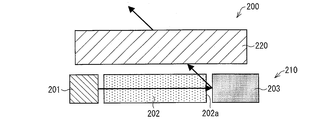
- FIG. 6 is a cross-sectional view showing a liquid crystal display device 200 including the backlight unit 210.
- the backlight unit 210 includes a light guide plate 202 disposed to face the liquid crystal panel 220, a light source 201 such as an LED disposed on the side of the light guide plate 202, and a frame 203 that holds these. Light incident on the light guide plate 202 from the light source 201 propagates through the light guide plate 202 and is emitted from the upper surface to illuminate the liquid crystal panel 220.
- the backlight unit 210 shown in FIG. 6 there is a problem that light energy is lost in the light incident on the light guide plate 202.
- the light reaching the end surface 202a opposite to the light incident surface of the light guide plate 202 is scattered by the unevenness of the end surface 202a, or the light leaking from the end surface 202a is scattered by the frame 203, The light from the light source 201 cannot be fully utilized.
- the liquid crystal panel 230 it is displayed as a bright line, which causes a problem that the display quality of the liquid crystal display device 200 is deteriorated.
- Patent Document 1 discloses a technique for suppressing scattered light in a light guide plate.
- FIG. 7 is a diagram showing the backlight unit 310 described in Patent Document 1.
- the reflection diffraction element 303 is disposed on the end surface 302 a of the light guide plate 302 opposite to the light source 301.
- the light that has passed through the end surface 302 a so far is diffracted by the reflection diffraction element 303 and is emitted from the upper surface of the light guide plate 302. Thereby, the light use efficiency in the backlight unit 310 is improved.
- Japanese Patent Publication Japanese Patent Laid-Open No. 2006-294361 (published on October 26, 2006)”
- the present invention has been made in view of the above problems, and an object of the present invention is to provide a backlight unit and a liquid crystal display device with improved light utilization efficiency with a simple configuration.
- a backlight unit includes a light guide plate and a light source disposed to face one end surface of the light guide plate, and the light guide plate from the light source through the one end surface.
- the opposite end surface of the light guide plate located on the side opposite to the one end surface has one or more convex shapes toward the peak direction of light emitted from the light source, and the convex surface is the main surface. It is characterized by being comprised from two or more inclined surfaces inclined with respect to the direction perpendicular
- the traveling direction of light showing a luminance peak among the light emitted from the light source is referred to as a peak direction.
- the light parallel to the peak direction reaches the opposite end located on the opposite side of the light source.
- the opposite end surface of the light guide plate is inclined or curved with respect to the peak direction. For this reason, the light that has reached the opposite end is reflected by the opposite end surface and returns into the light guide plate. As a result, light scattering and reflection in the vicinity of the opposite end are suppressed, and loss of light energy is suppressed.
- the opposite end surface becomes two or more convex shapes in the peak direction, it can be paraphrased that the reflection end surface becomes uneven in the peak direction.
- the opposite end surface has a simple shape such as an inclined surface or a curved surface, it can be easily formed by injection molding of a light guide plate or the like.
- a liquid crystal display device includes the above-described backlight unit and a liquid crystal panel.
- the backlight unit according to the present invention includes a light guide plate and a light source disposed to face one end surface of the light guide plate, and transmits light incident on the light guide plate from the light source through the one end surface.
- An edge light type backlight unit that emits a surface from one main surface of the light guide plate, wherein an opposite end surface of the light guide plate that is opposite to the one end surface is directed toward a peak direction of light emitted from the light source. It comprises one or more convex shapes and two or more slopes inclined with respect to a direction perpendicular to the main surface, or one or more curved surfaces curved with respect to the perpendicular direction. . For this reason, the planar light source unit which improved the brightness
- FIG. 1 is a cross-sectional view schematically showing the configuration of the liquid crystal display device 100 of the present embodiment.
- the liquid crystal display device 100 includes a backlight unit 10 and a liquid crystal panel 20 disposed above the backlight unit 10.
- the liquid crystal panel 20 may be a known liquid crystal panel, and is not particularly limited.
- the backlight unit 10 includes a light source 1, a light guide plate 2, a frame 3, a reflection sheet 4, and an optical sheet 5.
- the backlight unit 10 is an edge light type backlight unit that emits light that has entered the light incident end surface 2 a of the light guide plate 2 from the light source 1 from one main surface of the light guide plate 2.
- the main surface on the light emitting side of the light guide plate 2 will be described as the upper surface, and the main surface on the opposite side will be described as the lower surface.
- the light source 1 is disposed to face a light incident end surface (one end surface) 2a which is at least one end surface of the light guide plate 2, and irradiates light toward the light incident end surface 2a.
- a light emitting diode Light Emitting Diode: LED
- LED Light Emitting Diode
- the light emitted from the light source 1 has a certain degree of directivity, and in the following description, the traveling direction of light having the highest luminance among the light emitted from the light source 1 is referred to as a peak direction.
- the peak direction is indicated by an arrow extending rightward from the light source 1.
- FIG. 1 shall show the cross section which passes along the direction (thickness direction of the light-guide plate 2) perpendicular
- the light guide plate 2 is a transparent plate disposed to face the liquid crystal panel 20, and the light source 1 is disposed on the light incident end surface 2a side.
- the light incident end surface 2 a of the light guide plate 2 and the opposite end surface 2 b on the opposite side thereof are located on the peak direction of the light emitted from the light source 1.
- the opposite end surface 2b of the light guide plate 2 is formed in a convex shape toward the peak direction.
- the opposite end surface 2 b is composed of two inclined surfaces that are inclined with respect to the thickness direction of the light guide plate 2.
- the opposite end surface 2b corresponds to a triangular isosceles side in FIG.
- the inclination angle of the opposite end surface 2b with respect to the thickness direction of the light guide plate 2 is not particularly limited, and may be set as appropriate so as to reflect light parallel to the peak direction in consideration of the refractive index and the like. Is possible.
- the light guide plate 2 having the above-described configuration can be suitably formed from a resin or the like by injection (injection formation).
- the frame 3 houses the light source 1 and the light guide plate 2 and holds them.
- the part facing the opposite end surface 2b of the light guide plate 2 has an uneven shape combined with the shape of the opposite end surface 2b. Thereby, the light that has reached the opposite end face 2b can be reflected more suitably.
- the reflection sheet 4 is provided so as to face the lower surface of the light guide plate 2, and has light reflectivity so that light emitted from the lower surface of the light guide plate 2 is reflected inside the light guide plate 2.
- the optical sheet 5 is provided so as to face the upper surface of the light guide plate 2, and has a configuration in which the light emitted from the upper surface of the light guide plate 2 is uniformed and condensed to irradiate the liquid crystal panel 20.
- the light emitted from the light source 1 enters the light guide plate 2 through the light incident end surface 2a and propagates while reflecting the inside thereof.
- Light propagating in the light guide plate 2 is reflected by the reflection sheet 4 in the process, emitted from the upper surface of the light guide plate 2, and irradiated (surface emission) toward the liquid crystal panel 20 through the optical sheet 5.
- the light having the strongest brightness travels straight from the light incident end surface 2a and reaches the opposite end surface 2b. Since the opposite end surface 2b has a slope inclined with respect to the peak direction which is the traveling direction of the light, the light reaching the opposite end surface 2b is reflected by the slope and returns into the light guide plate 2. In particular, when the opposite end face 2b corresponds to a triangular isosceles side in FIG. 1, the light can be reflected more suitably.
- the light reaching the opposite end surface 2b is reflected between one inclined surface on the opposite end surface 2b and the other one inclined surface, and then into the light guide plate 2. You may return.
- the light reflected by the opposite end surface 2 b and returned into the light guide plate 2 is finally emitted from the upper surface of the light guide plate 2 toward the liquid crystal panel 20.
- the backlight unit 10 in the backlight unit 10 according to the present embodiment, scattering and reflection of light in the vicinity of the opposite end surface 2b is suppressed, and light utilization efficiency can be increased. Thereby, the luminance of the backlight unit 10 can be improved by about 3%. Furthermore, since the power consumption of the backlight unit 10 can be reduced by this brightness improvement, the power consumption of the liquid crystal display device 100 can be reduced.
- the display quality of the liquid crystal display device 100 can be improved by suppressing the light scattering and reflection in the backlight unit 10.
- Modification of light guide plate 2 In the light guide plate 2, the shape of the opposite end surface 2b is not limited to the shape shown in FIG. Hereinafter, modified examples of the light guide plate 2 will be described.
- the opposite end surface 2 b of the light guide plate 2 may be formed of a curved surface that is curved with respect to the thickness direction of the light guide plate 2.
- FIG. 2 is a view showing a light guide plate 6 according to a modification.
- the opposite end face 6b preferably corresponds to a semicircular arc.
- the degree of curvature of the opposite end face 6b with respect to the thickness direction of the light guide plate 6 is not particularly limited, and can be appropriately set so as to reflect light parallel to the peak direction in consideration of the refractive index and the like.
- the light that has reached the opposite end surface 6 b is reflected by the curved surface and returns into the light guide plate 2, so that the light near the opposite end surface 6 b is similar to the embodiment shown in FIG. 1. Scattered reflection can be suppressed.
- the opposite end surface 2b of the light guide plate 2 may be composed of two or more slopes or two or more curved surfaces so as to form two or more convex shapes toward the peak direction.
- the opposite end surface 12b of the light guide plate 12 according to the modification may be configured by four inclined surfaces so as to form two convex shapes toward the peak direction.
- FIG. 3 is a cross-sectional view showing a light guide plate 12 according to a modification.
- the opposite end surface 12b preferably corresponds to the isosceles sides of each of the two triangular shapes in FIG.
- the opposite end surface 16b of the light guide plate 16 according to the modification may be formed of two curved surfaces so as to form two convex shapes toward the peak direction.
- FIG. 4 is a cross-sectional view showing a light guide plate 16 according to a modification.
- the opposite end face 16b preferably corresponds to each of the two semicircular arcs in FIG.
- the number of the convex shapes formed by the opposite end surface 2b of the light guide plate 2 is not limited to the above example, and can be increased.
- the frame 3 has an uneven shape combined with the shape of the opposite end surface of the light guide plate.
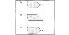
- the backlight unit 10 according to the present embodiment has an advantage in terms of reducing the outer size. This advantage will be described with reference to FIG.
- a light guide plate having an opposite end surface composed of one inclined surface is used as a comparative example.
- FIG. 5 is a schematic view showing opposite end faces of various light guide plates, (a) showing the opposite end face 2b according to the present embodiment, (b) showing the opposite end face according to the comparative example, and (c).
- the opposite end surface 6b which concerns on the other example of this embodiment is shown.
- 5A to 5C show cross sections passing through the thickness direction and the peak direction of the light guide plate, respectively.
- the opposite end surfaces shown in FIGS. 5A to 5C are all set so as to optimally reflect the light parallel to the peak direction.
- the opposite end face 2b shown in FIG. 5A and the opposite end face shown in FIG. 5B have an inclination angle of 45 degrees with respect to the peak direction.
- the opposite end surface 6b has drawn the arc of a semicircle.
- the length from the inner side of the opposite end surface (intersection of the upper surface of the light guide plate to the inclined surface or curved surface) to the outer side (the end portion of the light guide plate) is the same as that of the present embodiment (FIG. 5).
- (A) and (c)) are shorter than the comparative example (FIG. 5B). That is, according to the present embodiment, the light use efficiency in the backlight unit 10 can be increased without increasing the outer shape of the light guide plate 2 to the outside.
- the outer shape of the light guide plate 2 can be further reduced in size.
- the opposite end surface 2b which comprises one convex shape is shown with the dotted line.
- the opposite end face having two convex shapes can be made smaller in size than the opposite end face 12 b having one convex shape.
- the opposite end face 6b having one convex shape is shown by a dotted line.
- the opposite end surface having two convex shapes can reduce the outer shape of the light guide plate 2 rather than the opposite end surface having one convex shape. I understand that I can do it.
- a backlight unit includes a light guide plate and a light source disposed to face one end surface of the light guide plate, and the light guide plate from the light source through the one end surface.
- the opposite end surface of the light guide plate that is opposite to the one end surface has one or more convex shapes toward the peak direction of the light emitted from the light source, and is perpendicular to the main surface. It is characterized by being composed of two or more inclined surfaces that are inclined with respect to each other, or two or more curved surfaces that are curved with respect to the perpendicular direction.
- the light parallel to the peak direction reaches the opposite end located on the opposite side of the light source.
- the opposite end surface of the light guide plate is inclined or curved with respect to the peak direction. For this reason, the light that has reached the opposite end is reflected by the opposite end surface and returns into the light guide plate. Thereby, scattering reflection of light in the vicinity of the opposite end is suppressed, and loss of light energy is suppressed.
- the opposite end surface becomes two or more convex shapes in the peak direction, it can be paraphrased that the reflection end surface becomes uneven in the peak direction.
- the opposite end surface has a simple shape such as an inclined surface or a curved surface, it can be easily formed by injection molding of a light guide plate or the like.
- the opposite end surface of the light guide plate is composed of the two or more inclined surfaces, and the opposite end surface passes through a direction perpendicular to the main surface and the peak direction.
- the cross section preferably corresponds to one or more triangular isosceles sides.
- the light utilization efficiency can be further increased.
- the opposite end surface of the light guide plate is configured by the one or more curved surfaces, and the opposite end surface passes through a direction perpendicular to the main surface and the peak direction.
- the cross section preferably corresponds to one or more semicircular arcs.
- the light utilization efficiency can be further increased.
- the backlight unit according to the present invention preferably further includes a frame for holding the light guide plate and the light source, and a portion of the frame facing the opposite end surface is preferably combined with the opposite end surface.
- the light utilization efficiency can be further increased.
- a liquid crystal display device includes the above-described backlight unit and a liquid crystal panel.
- the power consumption of the planar light source unit can be reduced, so that the power consumption of the liquid crystal display device can be reduced.
- the present invention can be widely used as an energy-saving backlight unit and a liquid crystal display device.
Landscapes
- Physics & Mathematics (AREA)
- Nonlinear Science (AREA)
- General Physics & Mathematics (AREA)
- Optics & Photonics (AREA)
- Mathematical Physics (AREA)
- Chemical & Material Sciences (AREA)
- Crystallography & Structural Chemistry (AREA)
- Planar Illumination Modules (AREA)
- Engineering & Computer Science (AREA)
- General Engineering & Computer Science (AREA)
- Illuminated Signs And Luminous Advertising (AREA)
- Light Guides In General And Applications Therefor (AREA)
Abstract
Description
上記導光板における上記一端面とは反対側に位置する反対端面は、上記光源から出射する光のピーク方向に向かって1つ以上の凸状を成すと共に、当該凸状の表面は、上記主面に対して垂直な方向に対して傾斜する2つ以上の斜面、または、当該垂直な方向に対して湾曲した1つ以上の曲面から構成されることを特徴としている。
液晶表示装置100の概略的な構成について図1を参照して以下に説明する。図1は、本実施形態の液晶表示装置100の構成を概略的に示す断面図である。
導光板2において、反対端面2bの形状は図1に示す形状に限られない。以下、導光板2の変形例について説明する。
本実施形態に係るバックライトユニット10は、その外形サイズの小型化に関しても有利な点を有する。この利点について、図5を参照して説明する。
本発明に係るバックライトユニットは、上記課題を解決するために、導光板と、導光板の一端面に対向して配置された光源とを備え、上記光源から上記一端面を介して上記導光板に入射した光を当該導光板の一方の主面から面放射させるエッジライト型のバックライトユニットであって、
上記導光板における上記一端面とは反対側に位置する反対端面は、上記光源から出射する光のピーク方向に向かって1つ以上の凸状を成すと共に、上記主面に対して垂直な方向に対して傾斜する2つ以上の斜面、または、当該垂直な方向に対して湾曲した2つ以上曲面から構成されることを特徴としている。
2、6、12、16 導光板
2a、6a、12a、16a 入光端面
2b、6b、12b、16b 反対端部
3 フレーム
4 反射シート
5 光学シート
10 バックライトユニット
20 液晶パネル
100 液晶表示装置
Claims (5)
- 導光板と、導光板の一端面に対向して配置された光源とを備え、上記光源から上記一端面を介して上記導光板に入射した光を当該導光板の一方の主面から面放射させるエッジライト型のバックライトユニットであって、
上記導光板における上記一端面とは反対側に位置する反対端面は、上記光源から出射する光のピーク方向に向かって1つ以上の凸状を成すと共に、当該凸状の表面は、上記主面に対して垂直な方向に対して傾斜する2つ以上の斜面、または、当該垂直な方向に対して湾曲した1つ以上の曲面から構成されることを特徴とするバックライトユニット。 - 上記導光板の上記反対端面は、上記2つ以上の斜面から構成され、
上記反対端面は、上記主面に対して垂直な方向および上記ピーク方向を通る断面において、1つ以上の三角形状の二等辺に対応することを特徴とする請求項1に記載のバックライトユニット。 - 上記導光板の上記反対端面は、上記1つ以上の曲面から構成され、
上記反対端面は、上記主面に対して垂直な方向および上記ピーク方向を通る断面において、1つ以上の半円形状の弧に対応することを特徴とする請求項1に記載のバックライトユニット。 - 上記導光板および上記光源を保持するフレームをさらに備え、
上記フレームにおいて上記反対端面に対向する部位は、当該反対端面と組み合わさる形状であることを特徴とする請求項1から3のいずれか1項に記載のバックライトユニット。 - 請求項1から4のいずれか1項に記載のバックライトユニットと液晶パネルとを備えることを特徴とする液晶表示装置。
Priority Applications (4)
| Application Number | Priority Date | Filing Date | Title |
|---|---|---|---|
| SG2012079042A SG185030A1 (en) | 2010-04-27 | 2011-02-23 | Backlight unit and liquid crystal display device |
| US13/642,893 US8891040B2 (en) | 2010-04-27 | 2011-02-23 | Backlight unit and liquid crystal display device |
| AU2011246457A AU2011246457A1 (en) | 2010-04-27 | 2011-02-23 | Backlight unit and liquid crystal display device |
| JP2012512698A JPWO2011135907A1 (ja) | 2010-04-27 | 2011-02-23 | バックライトユニットおよび液晶表示装置 |
Applications Claiming Priority (2)
| Application Number | Priority Date | Filing Date | Title |
|---|---|---|---|
| JP2010102489 | 2010-04-27 | ||
| JP2010-102489 | 2010-04-27 |
Publications (1)
| Publication Number | Publication Date |
|---|---|
| WO2011135907A1 true WO2011135907A1 (ja) | 2011-11-03 |
Family
ID=44861228
Family Applications (1)
| Application Number | Title | Priority Date | Filing Date |
|---|---|---|---|
| PCT/JP2011/054022 Ceased WO2011135907A1 (ja) | 2010-04-27 | 2011-02-23 | バックライトユニットおよび液晶表示装置 |
Country Status (5)
| Country | Link |
|---|---|
| US (1) | US8891040B2 (ja) |
| JP (1) | JPWO2011135907A1 (ja) |
| AU (1) | AU2011246457A1 (ja) |
| SG (1) | SG185030A1 (ja) |
| WO (1) | WO2011135907A1 (ja) |
Cited By (3)
| Publication number | Priority date | Publication date | Assignee | Title |
|---|---|---|---|---|
| JP2013156293A (ja) * | 2012-01-26 | 2013-08-15 | Sharp Corp | 液晶表示装置 |
| US20140043559A1 (en) * | 2012-08-08 | 2014-02-13 | Joo Young Lee | Light guide plate, backlight unit including the same and liquid crystal display including the backlight unit |
| WO2017183661A1 (ja) * | 2016-04-22 | 2017-10-26 | 川崎重工業株式会社 | 導光板及び面照明装置 |
Families Citing this family (5)
| Publication number | Priority date | Publication date | Assignee | Title |
|---|---|---|---|---|
| CN203025371U (zh) * | 2011-05-19 | 2013-06-26 | 深圳市华星光电技术有限公司 | 导光板及背光显示模块 |
| CN105204229B (zh) * | 2015-10-20 | 2018-09-04 | 武汉华星光电技术有限公司 | 具非平面侧向结构的背光模块及液晶显示装置 |
| JP2019123426A (ja) * | 2018-01-18 | 2019-07-25 | ダイキョーニシカワ株式会社 | 車両用内装品 |
| DE102020201644A1 (de) | 2020-02-11 | 2021-08-12 | Volkswagen Aktiengesellschaft | Beleuchtungsvorrichtung für ein Kraftfahrzeug |
| JP2025049878A (ja) * | 2023-09-22 | 2025-04-04 | シャープディスプレイテクノロジー株式会社 | 液晶モジュール、及び、ヘッドマウントディスプレイ |
Citations (6)
| Publication number | Priority date | Publication date | Assignee | Title |
|---|---|---|---|---|
| JPH0519255A (ja) * | 1991-07-09 | 1993-01-29 | Hitachi Ltd | 面光源装置 |
| JPH05142538A (ja) * | 1991-11-21 | 1993-06-11 | Hitachi Ltd | 液晶表示装置 |
| JPH11242122A (ja) * | 1997-12-22 | 1999-09-07 | Sanyo Electric Co Ltd | 導光板、その導光板を用いた面光源及び表示装置 |
| JP2001014923A (ja) * | 1999-06-29 | 2001-01-19 | Seiko Epson Corp | 面光源ユニットならびにそれを備える表示装置および電子機器 |
| WO2004055429A1 (ja) * | 2002-12-18 | 2004-07-01 | Sharp Kabushiki Kaisha | 導光板およびそれを備えた照明装置、平面光源装置ならびに表示装置 |
| JP2004296300A (ja) * | 2003-03-27 | 2004-10-21 | Fujitsu Ltd | 両面発光光源 |
Family Cites Families (7)
| Publication number | Priority date | Publication date | Assignee | Title |
|---|---|---|---|---|
| US20100302479A1 (en) * | 1996-03-21 | 2010-12-02 | Aronson Joseph T | Optical article |
| JP4556749B2 (ja) * | 2005-04-08 | 2010-10-06 | 凸版印刷株式会社 | 導光板および表示装置 |
| WO2010004801A1 (ja) * | 2008-07-07 | 2010-01-14 | シャープ株式会社 | 照明装置および液晶表示装置 |
| JP2010026280A (ja) * | 2008-07-22 | 2010-02-04 | Hitachi Maxell Ltd | 液晶表示装置 |
| US7980748B2 (en) | 2008-08-28 | 2011-07-19 | Sharp Kabushiki Kaisha | Lighting system including light guide with reflective micro structures on edge surfaces |
| BRPI0918817A2 (pt) * | 2008-08-29 | 2015-12-01 | Sharp Kk | sensor de coordenadas, dispositivo eletrônico, dispositivo de exibição, unidade de recepção de luz |
| KR101676870B1 (ko) * | 2009-07-31 | 2016-11-16 | 엘지전자 주식회사 | 백라이트 유닛 및 그를 이용한 디스플레이 장치 |
-
2011
- 2011-02-23 AU AU2011246457A patent/AU2011246457A1/en not_active Abandoned
- 2011-02-23 JP JP2012512698A patent/JPWO2011135907A1/ja active Pending
- 2011-02-23 US US13/642,893 patent/US8891040B2/en not_active Expired - Fee Related
- 2011-02-23 SG SG2012079042A patent/SG185030A1/en unknown
- 2011-02-23 WO PCT/JP2011/054022 patent/WO2011135907A1/ja not_active Ceased
Patent Citations (6)
| Publication number | Priority date | Publication date | Assignee | Title |
|---|---|---|---|---|
| JPH0519255A (ja) * | 1991-07-09 | 1993-01-29 | Hitachi Ltd | 面光源装置 |
| JPH05142538A (ja) * | 1991-11-21 | 1993-06-11 | Hitachi Ltd | 液晶表示装置 |
| JPH11242122A (ja) * | 1997-12-22 | 1999-09-07 | Sanyo Electric Co Ltd | 導光板、その導光板を用いた面光源及び表示装置 |
| JP2001014923A (ja) * | 1999-06-29 | 2001-01-19 | Seiko Epson Corp | 面光源ユニットならびにそれを備える表示装置および電子機器 |
| WO2004055429A1 (ja) * | 2002-12-18 | 2004-07-01 | Sharp Kabushiki Kaisha | 導光板およびそれを備えた照明装置、平面光源装置ならびに表示装置 |
| JP2004296300A (ja) * | 2003-03-27 | 2004-10-21 | Fujitsu Ltd | 両面発光光源 |
Cited By (9)
| Publication number | Priority date | Publication date | Assignee | Title |
|---|---|---|---|---|
| JP2013156293A (ja) * | 2012-01-26 | 2013-08-15 | Sharp Corp | 液晶表示装置 |
| US20140043559A1 (en) * | 2012-08-08 | 2014-02-13 | Joo Young Lee | Light guide plate, backlight unit including the same and liquid crystal display including the backlight unit |
| KR20140021146A (ko) * | 2012-08-08 | 2014-02-20 | 삼성디스플레이 주식회사 | 도광판, 이를 포함하는 백라이트 유닛 및 액정 표시 장치 |
| US9632234B2 (en) * | 2012-08-08 | 2017-04-25 | Samsung Display Co., Ltd. | Light guide plate, backlight unit including the same and liquid crystal display including the backlight unit |
| KR102031686B1 (ko) * | 2012-08-08 | 2019-10-15 | 삼성디스플레이 주식회사 | 도광판, 이를 포함하는 백라이트 유닛 및 액정 표시 장치 |
| WO2017183661A1 (ja) * | 2016-04-22 | 2017-10-26 | 川崎重工業株式会社 | 導光板及び面照明装置 |
| JP2017195163A (ja) * | 2016-04-22 | 2017-10-26 | 川崎重工業株式会社 | 導光板及び面照明装置 |
| CN109073171A (zh) * | 2016-04-22 | 2018-12-21 | 川崎重工业株式会社 | 导光板及面照明装置 |
| US10677979B2 (en) | 2016-04-22 | 2020-06-09 | Kawasaki Jukogyo Kabushiki Kaisha | Light guide plate and surface-lighting device |
Also Published As
| Publication number | Publication date |
|---|---|
| JPWO2011135907A1 (ja) | 2013-07-18 |
| US20130038817A1 (en) | 2013-02-14 |
| SG185030A1 (en) | 2012-11-29 |
| US8891040B2 (en) | 2014-11-18 |
| AU2011246457A1 (en) | 2012-11-29 |
Similar Documents
| Publication | Publication Date | Title |
|---|---|---|
| WO2011135907A1 (ja) | バックライトユニットおよび液晶表示装置 | |
| CN100555037C (zh) | 背光模组 | |
| US8136955B2 (en) | Illumination system and display including same | |
| JP7017473B2 (ja) | 面光源装置 | |
| WO2013008569A1 (ja) | 照明装置及び表示装置 | |
| KR20090034608A (ko) | 일체형 도광판과 이를 구비하는 백라이트장치 | |
| WO2004055429A1 (ja) | 導光板およびそれを備えた照明装置、平面光源装置ならびに表示装置 | |
| CN102640039A (zh) | 液晶显示装置 | |
| JP2006294361A (ja) | 導光板および表示装置 | |
| CN101630037A (zh) | 背光模组及其导光板 | |
| WO2013005559A1 (ja) | 照明装置および表示装置 | |
| US20160187556A1 (en) | Super directional light guide film and thin film type back light unit for flat panel display using the same | |
| JP2014130748A (ja) | 導光板及び面光源装置 | |
| JP4849335B2 (ja) | ライトガイド、バックライト装置及び光源装置 | |
| CN102691936A (zh) | 背光模组及液晶显示装置 | |
| JP2014132557A (ja) | バックライトアセンブリとそれを利用した表示装置 | |
| CN108885302B (zh) | 照明装置和显示装置 | |
| TW201305630A (zh) | 具有橢圓底片段之對稱鋸齒邊緣光導膜 | |
| JP5306029B2 (ja) | バックライトおよびそれを備えた表示装置 | |
| WO2010001653A1 (ja) | 導光体ユニット、面光源装置、および液晶表示装置 | |
| WO2012144409A1 (ja) | 照明装置および表示装置 | |
| JP2005228718A (ja) | 導光板 | |
| WO2016082249A1 (zh) | 导光板、背光模组及显示器 | |
| WO2012165474A1 (ja) | 発光素子、調光素子、表示装置および照明装置 | |
| WO2013154038A1 (ja) | 照明装置及びそれを備えた表示装置 |
Legal Events
| Date | Code | Title | Description |
|---|---|---|---|
| 121 | Ep: the epo has been informed by wipo that ep was designated in this application |
Ref document number: 11774691 Country of ref document: EP Kind code of ref document: A1 |
|
| WWE | Wipo information: entry into national phase |
Ref document number: 2012512698 Country of ref document: JP |
|
| WWE | Wipo information: entry into national phase |
Ref document number: 13642893 Country of ref document: US |
|
| NENP | Non-entry into the national phase |
Ref country code: DE |
|
| ENP | Entry into the national phase |
Ref document number: 2011246457 Country of ref document: AU Date of ref document: 20110223 Kind code of ref document: A |
|
| 122 | Ep: pct application non-entry in european phase |
Ref document number: 11774691 Country of ref document: EP Kind code of ref document: A1 |