WO2011132279A1 - 画像処理装置、方法、及び記録媒体 - Google Patents
画像処理装置、方法、及び記録媒体 Download PDFInfo
- Publication number
- WO2011132279A1 WO2011132279A1 PCT/JP2010/057083 JP2010057083W WO2011132279A1 WO 2011132279 A1 WO2011132279 A1 WO 2011132279A1 JP 2010057083 W JP2010057083 W JP 2010057083W WO 2011132279 A1 WO2011132279 A1 WO 2011132279A1
- Authority
- WO
- WIPO (PCT)
- Prior art keywords
- image
- colors
- correction
- blur
- raw
- Prior art date
- Legal status (The legal status is an assumption and is not a legal conclusion. Google has not performed a legal analysis and makes no representation as to the accuracy of the status listed.)
- Ceased
Links
Images


Classifications
-
- H—ELECTRICITY
- H04—ELECTRIC COMMUNICATION TECHNIQUE
- H04N—PICTORIAL COMMUNICATION, e.g. TELEVISION
- H04N25/00—Circuitry of solid-state image sensors [SSIS]; Control thereof
- H04N25/60—Noise processing, e.g. detecting, correcting, reducing or removing noise
- H04N25/61—Noise processing, e.g. detecting, correcting, reducing or removing noise the noise originating only from the lens unit, e.g. flare, shading, vignetting or "cos4"
- H04N25/611—Correction of chromatic aberration
-
- H—ELECTRICITY
- H04—ELECTRIC COMMUNICATION TECHNIQUE
- H04N—PICTORIAL COMMUNICATION, e.g. TELEVISION
- H04N23/00—Cameras or camera modules comprising electronic image sensors; Control thereof
- H04N23/10—Cameras or camera modules comprising electronic image sensors; Control thereof for generating image signals from different wavelengths
- H04N23/12—Cameras or camera modules comprising electronic image sensors; Control thereof for generating image signals from different wavelengths with one sensor only
-
- H—ELECTRICITY
- H04—ELECTRIC COMMUNICATION TECHNIQUE
- H04N—PICTORIAL COMMUNICATION, e.g. TELEVISION
- H04N23/00—Cameras or camera modules comprising electronic image sensors; Control thereof
- H04N23/80—Camera processing pipelines; Components thereof
- H04N23/84—Camera processing pipelines; Components thereof for processing colour signals
- H04N23/843—Demosaicing, e.g. interpolating colour pixel values
-
- H—ELECTRICITY
- H04—ELECTRIC COMMUNICATION TECHNIQUE
- H04N—PICTORIAL COMMUNICATION, e.g. TELEVISION
- H04N2209/00—Details of colour television systems
- H04N2209/04—Picture signal generators
- H04N2209/041—Picture signal generators using solid-state devices
- H04N2209/042—Picture signal generators using solid-state devices having a single pick-up sensor
- H04N2209/045—Picture signal generators using solid-state devices having a single pick-up sensor using mosaic colour filter
- H04N2209/046—Colour interpolation to calculate the missing colour values
-
- H—ELECTRICITY
- H04—ELECTRIC COMMUNICATION TECHNIQUE
- H04N—PICTORIAL COMMUNICATION, e.g. TELEVISION
- H04N25/00—Circuitry of solid-state image sensors [SSIS]; Control thereof
- H04N25/10—Circuitry of solid-state image sensors [SSIS]; Control thereof for transforming different wavelengths into image signals
- H04N25/11—Arrangement of colour filter arrays [CFA]; Filter mosaics
- H04N25/13—Arrangement of colour filter arrays [CFA]; Filter mosaics characterised by the spectral characteristics of the filter elements
- H04N25/134—Arrangement of colour filter arrays [CFA]; Filter mosaics characterised by the spectral characteristics of the filter elements based on three different wavelength filter elements
Definitions
- the present invention relates to an image restoration process for correcting blurring of a captured image.
- an imaging apparatus such as a digital camera or a digital video camera
- light from a subject is incident on a sensor having a plurality of elements such as a CCD and a CMOS through an imaging optical system including lenses.
- the sensor In the sensor, light passing through the imaging optical system is converted into an electrical signal.
- a captured image can be obtained by performing processing necessary for imaging such as A / D conversion processing and demosaic processing on the electric signal.
- the image quality of this captured image is affected by the imaging optical system.
- a clear image with small blur can be obtained.
- the captured image obtained when using a lens with poor performance is blurred.
- an image shot using a lens with a small blur is like a point where each star is clear.
- the stars are blurred with a spread rather than a single point.
- PSF Point Spread Function
- the PSF is one point, and in an imaging optical system with large blur, the PSF is not a small point but has a certain extent.
- a captured image captured using an ideal imaging optical system that does not cause blur is defined as f (x, y).
- x and y are variables indicating the two-dimensional position of the captured image, and f (x, y) represents the pixel value at the position x and y.
- g (x, y) a photographed image photographed with an imaging optical system that causes blurring
- the PSF of the imaging optical system that causes the blur is h (x, y).
- h (x, y) is determined by, for example, lens characteristics, photographing parameters (diaphragm diameter, object position, zoom position, etc.), transmittance of a color filter of the sensor, and the like.
- h (x, y) may be determined by measuring a two-dimensional light distribution on the sensor surface when a point light source is imaged. The following relationship holds for f (x, y), g (x, y), and h (x, y).
- g (x, y) h (x, y) * f (x, y) (1) * Means convolution (convolution integration).
- the correction of blur is an ideal imaging optical system based on a captured image g (x, y) captured by the imaging optical system that causes blur and h (x, y) that is a PSF of the imaging optical system.
- f (x, y) obtained in (1) can be estimated.
- G (u, v) H (u, v) ⁇ F (u, v) (2)
- H (u, v) is a Fourier transform of h (x, y), which is a PSF, and is called an optical transfer function (OTF: Optical Transfer Function).
- u and v represent coordinates on a two-dimensional frequency plane, that is, frequencies.
- G (u, v) is a Fourier transform of g (x, y) (Fourier display), and F (u, v) is a Fourier transform of f (x, y).
- both sides may be divided by H as follows.
- G (u, v) / H (u, v) F (u, v) (3)
- An ideal image f (x, y) without blur can be obtained as a restored image by performing inverse Fourier transform on this F (u, v) and returning it to the actual surface.
- the inverse filter R (x, y), which is the reciprocal thereof, increases as the frequency increases. Therefore, when a convolution process is performed on a blurred photographed image using an inverse filter, the high frequency component of the photographed image is enhanced. In an actual captured image, noise is also included, and since noise is generally high frequency, the inverse filter may emphasize noise.
- a Wiener filter in which the inverse filter R (x, y) is modified so as not to eliminate the inability to calculate due to the occurrence of division by zero as described above or to emphasize high-frequency noise too much.
- a filter used for blur correction such as an inverse filter or a Wiener filter is referred to as an image restoration filter.
- Many imaging devices such as digital cameras and digital video cameras acquire color information by arranging a color filter composed of a plurality of specific colors in front of a sensor having a plurality of elements such as a CCD and a CMOS. .
- This method is called a single plate type.
- signals of other colors cannot be obtained from elements corresponding to a color filter of a specific color. Therefore, signals of other colors are obtained by interpolation from signals from neighboring elements.
- This interpolation processing is called demosaicing processing (demosaicing processing).
- RAW data an image before demosaic processing is referred to as RAW data.
- the OTF varies depending on the shooting conditions such as aperture diameter and zoom position. Therefore, the image restoration filter used for the image restoration process also needs to be changed according to the shooting state.
- Various image processing such as gamma processing and color conversion processing is performed on the image data acquired by the imaging device in order to improve image quality.
- image recovery processing The effect may be reduced.
- the blur characteristics of the input image substantially change.
- the images are mixed between the channels, and the G and B channel images other than the R channel are also blurred.
- the image restoration process is performed based on the amount of blur assumed from the optical characteristics for the G and B channels, the restoration is insufficient.
- the imaging optical system tends to have a low response at high frequencies. In other words, the more detailed the subject, the more blurred.
- the high frequency response included in the captured image may become high. This phenomenon is called a moire phenomenon. That is, the blur characteristic of the imaging optical system is substantially changed after demosaicing.
- the blur correction is performed on the image after demosaicing using the blur characteristic of the imaging optical system without considering these phenomena, the high-frequency component already having high response is further increased in the image after demosaking. As a result, a wave-like pattern is generated around the edge in the corrected image after blur correction (artifact such as ringing).
- Patent Document 1 assumes that an effective image restoration process can be performed by applying the image restoration process before the color conversion process. However, the image restoration process (image deterioration correction process) according to Patent Document 1 is performed on the demosaiced image.
- the problem to be solved by the present invention is that the blur characteristic of the captured image is changed by the demosaic at the time of blur correction of the imaging optical system, and as a result, good blur correction cannot be performed.
- the image processing apparatus of the present invention samples light incident on an imaging device including a color filter having a plurality of colors and a sensor with the sensor via the color filter.
- Input means for inputting RAW data corresponding to each of the plurality of colors obtained based on the data obtained by the above, and correcting blur of the RAW image indicated by the RAW data for each of the plurality of colors
- An acquisition means for acquiring a correction coefficient for correcting the blur of the RAW image indicated by the RAW data based on the correction coefficient acquired by the acquisition means for each of the plurality of colors
- FIG. 1 is a configuration diagram of an image pickup apparatus according to a first embodiment.
- Flow chart of processing according to embodiment 1 Example of sensor color filter array in Example 1
- FIG. 10 is a diagram illustrating an example of color plane division and zero insertion according to the first embodiment.
- Flow chart of blur correction processing according to embodiment 1 An example of a device configuration for realizing the functions of the first embodiment The figure showing the frequency characteristic concerning Example 1. The figure showing the frequency characteristic in two dimensions concerning Example 1 Example of filter used for demosaic of embodiment 1 The figure explaining the demosaic of Example 1
- Example 1 Hereinafter, an imaging apparatus that corrects blurring of a captured image caused by the imaging optical system according to the first embodiment will be described.
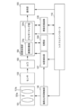
- FIG. 1 shows a basic configuration of the imaging apparatus of the present embodiment.
- Light that enters the imaging apparatus from a subject is imaged by the sensor 102 via the imaging optical system 101.
- Light (image) imaged by the sensor 102 is converted into an electric signal, and converted into a digital signal by the A / D converter 103.
- This digital signal is input to the image processing unit 104 as RAW data.
- the sensor 102 includes a photoelectric conversion element that converts an optical signal based on an image formed on the light receiving surface into an electrical signal for each pixel corresponding to the position.
- the sensor 102 has a function of performing color separation on the pixels on the light receiving surface using an RGB filter arranged in a checkered pattern arrangement shown in FIG.
- the RGB filter arrangement method and color separation in FIG. 3 are merely examples, and it goes without saying that the present invention can be applied to, for example, CMY and other filters that perform color separation.
- the image processing unit 104 includes an image restoration unit 104a that performs blur correction on the RAW data, and a demosaic unit 104b that performs demosaicing on the RAW data that has been subjected to blur correction.
- the state detection unit 107 obtains the image pickup state information (the state of the zoom position and the state of the aperture diameter) of the image pickup apparatus at the time of shooting (when the sensor 102 samples incident light). obtain.
- the state detection unit 107 may obtain shooting state information from the system controller 110 or may be obtained from the imaging optical system control unit 106.
- a correction coefficient corresponding to the imaging state information is acquired from the storage unit 108, and blur correction processing is performed on the RAW image indicated by the RAW data input to the image processing unit 104.
- the storage unit 108 stores the correction coefficient of the image restoration filter corresponding to each of the imaging state information.
- the correction coefficient corresponding to each imaging state stored in the storage unit 108 is determined by the optical characteristics of the imaging optical system of the imaging apparatus.
- an image restoration filter may be modeled and the model parameters may be stored as coefficients. In this case, an image restoration filter is appropriately generated based on the coefficient of the model parameter at the time of image restoration processing described later.
- Demosaking unit 104b performs demosaic processing on the RAW data indicating the RAW image subjected to the blur correction.
- the details of the configuration method of the image restoration filter and the processing contents of the image processing unit 104 will be described later.
- the corrected image data in which the blur of the imaging optical system 101 is corrected by the image processing unit 104 is stored in the image recording medium 109 or displayed on the display unit 105.
- FIG. 2 shows a processing flow relating to the image processing unit 104.
- step S101 the RAW data converted into a digital signal by the A / D converter 103 is acquired.
- the RAW data is desirably linear with respect to luminance so as to faithfully reflect the characteristics of the imaging optical system 101.
- RAW data having a non-linear value with respect to luminance is acquired, such as when the sensor 102 or the A / D converter 103 has non-linear characteristics.
- some non-linear processing may be performed within a range in which image characteristics such as missing pixel compensation are not significantly changed.
- step S102 the coefficient of the image restoration filter (or the coefficient of the model parameter) corresponding to the shooting state information is acquired from the storage unit.
- the coefficient of the image restoration filter is different for each color of RGB. This is because the blur characteristics are different for each RGB color plane. This point will be described later.
- step S103 for each of the RGB color planes, processing for correcting blur of the imaging optical system is performed on the RAW data using an image restoration filter. Details of the blur correction process will be described later.
- step S104 demosaic processing is performed on the RAW data that has undergone blur correction. Details of the demosaic process will be described later.
- step S201 the input raw data is divided into independent raw data for each color filter (independent color plane for each color filter) in accordance with the color filter arrangement shown in FIG.
- independent color plane for each color filter there is a pixel having no value in each color plane.
- the value of R at the pixel positions corresponding to G and B in the R plane image is unknown. Therefore, in step S202, zero is assigned to pixels having no value as shown in FIG.
- step S203 a corrected image is acquired by applying an image restoration filter for each color plane. Specifically, a convolution operation is performed between the raw data of each color plane with zero insertion and the image restoration filter of each color plane.
- the image restoration filter is different for each color plane as will be described later.
- step S204 zero insertion is performed on the RAW data of each color plane after convolution in the same manner as in step S202.
- the pixel in which zero insertion is performed in step S202 may have a value different from 0 after convolution, zero insertion is performed again in this step.
- step S205 the RAW data of each color plane zero-inserted in step S104 is synthesized as single plane output image data.
- the image data at the time when the color plane synthesis in step S205 is performed is in the RAW data format in which the demosaic is not performed as shown in FIG.
- ⁇ Image recovery filter configuration method> A configuration method of the image restoration filter used in the image restoration unit 104a will be described.
- the configuration method of the image restoration filter will be described with respect to the R plane, taking a Bayer array as an example.
- the R plane and the B plane are sampled every other pixel in the vertical and horizontal directions, and the same argument holds for the B plane.
- the color plane divided R plane image g R is expressed by the following equation.
- g R m R ⁇ (h R * f R) ⁇ (5)
- f R is an R component of the subject image f
- h R is a PSF corresponding to the R plane
- m R is a mask function (a function that becomes 1 at the R filter position and 0 at the G and B filter positions). is there.
- step S203 the image g R ′ after application of the image restoration filter for the R plane is expressed by the following equation.
- g R ′ R R * ⁇ m R ⁇ (h R * f R ) ⁇ (6)
- R R is an image restoration filter for the R plane.
- step S204 represented by image G R "the following equation after the mask processing.
- the R- plane image restoration filter RR is mathematically calculated so that the difference between R ′′ and m R ⁇ f R is minimized.
- the image restoration filters R B and R G for the B plane can be obtained for the B plane and the G plane. A configuration method of the image restoration filter will be described with reference to FIG.
- FIG. 7A is an OTF of the imaging optical system when the color filter arrangement is not taken into consideration. This is easy to understand if it is considered to mean the frequency characteristics of the imaging optical system when all the color filters are removed. Since sampling is performed by the sensor, there is no frequency higher than the Nyquist frequency.
- the inverse of this FIG. 7 (a) is taken to constitute a recovery filter as shown in FIG. 7 (b).
- the recovery filter since the OTF of the imaging optical system is smaller as the frequency is higher, the recovery filter has an effect of enhancing the higher frequency.
- sampling is performed every other pixel by the color filter array. Then, the OTF of the imaging optical system after sampling has a shape in which the OTF of the imaging optical system is folded with respect to the Nyquist frequency of R as shown in FIG. Since the frequency characteristic of the recovery filter is the reciprocal of FIG. 7C, it has a peak at the Nyquist of R as shown in FIG. 7D.
- the recovery filter of FIG. 7B is applied to the OTF of FIG. 7C, which is an actual blur characteristic, without considering sampling by the color filter array. Then, the obtained image becomes an image in which the high frequency is excessively emphasized as shown in FIG. That is, when blur correction is performed before demosaicing, it is necessary to use a recovery filter that takes into account the Nyquist frequency of each color derived from the color filter array.
- FIG. 8A shows the OTF when the color filter arrangement is not taken into consideration.
- the vertical axis and the horizontal axis mean the frequency in the vertical direction and the horizontal direction, respectively.
- the frequency response is displayed with contour lines.
- the frequency response is assumed to be equal on the contour lines. Since sampling is performed by the sensor, there is no frequency higher than the Nyquist frequency in both the vertical and horizontal directions.
- the inverse filter can be obtained by taking the inverse of OTF for each frequency in FIG. 8A and performing inverse Fourier transform.
- FIG. 8B shows a frequency response when turning back in the R plane is considered. Then, compared with the case where the filter arrangement of FIG. 8A is not considered, it can be seen that the response of high frequency is increased by folding in FIG. 8B.
- the image restoration filter construction method of this embodiment is characterized in that a restoration filter is obtained by performing Fourier transform by taking the reciprocal of the frequency characteristic of FIG. Since the frequency characteristic of R after being sampled by the filter array is FIG. 8 (b), if the inverse of FIG. 8 (a) is multiplied by FIG. 8 (b) without considering the filter array, the high frequency becomes excessive. It will be emphasized. The high frequency emphasized too much by the conventional method becomes a cause of occurrence of artifacts such as ringing. Since the present invention takes the reciprocal of the frequency characteristic after sampling, the high frequency is not overemphasized. It will be described that it is necessary to change the construction method of the image restoration filter depending on the filter arrangement. FIG.
- FIG. 8C shows the frequency characteristic of the G plane after sampling with the Bayer array. Comparing the G plane frequency characteristics of FIG. 8C and the R plane frequency characteristics of FIG. 8B, it can be seen that the folding is different. In other words, the R plane is folded in the form of a central square on the frequency plane, whereas the G plane is folded in the form of a rhombus. Therefore, when obtaining a recovery filter in consideration of aliasing in the present invention, since the aliasing method varies depending on the arrangement of each filter, it is necessary to change the configuration method of the recovery filter depending on the filter arrangement.
- demosaic by simple linear calculation Details of performing demosaicing on the RAW data after blur correction will be described.
- demosaic by simple linear calculation will be described. Take Bayer array as an example for illustration.
- the RAW data in each of the RGB color planes has pixels that have no value.
- FIG. 4 shows the state of each color plane after zero insertion has been performed on a pixel having no value.
- the convolution process may be performed for each filter shown in FIG. 9 on each color plane.
- the filter shown in FIG. 9A may be used for the R and B planes
- the filter shown in FIG. 9B may be used for the G plane.
- FIG. 10 shows how pixels are interpolated by this processing.
- FIG. 10A shows an example of the state of the G plane before demosaic processing. Since the center of FIG. 10A is an unknown pixel, 0 insertion is performed.
- FIG. 10B shows a state after convolution. It can be seen that the average of the upper, lower, left, and right pixels is assigned to the pixels that are unknown in FIG. Similarly, for the R and B planes, unknown pixels after convolution are interpolated by surrounding pixels.
- adaptive demosaic processing will be described as an example of demosaic processing including nonlinear processing.
- adaptive demosaic processing instead of simply taking the average of the surroundings as described above, the difference between the surrounding pixel values is taken in the vertical, horizontal, and diagonal directions, and the unknown pixels are used using the pixels in the direction with little change. Calculate the value. This is because more reliable interpolation can be performed by using pixel values in a direction in which the change is gentle.
- blur correction is performed before demosaicing, but the following problems arise when considering blur correction after adaptive processing.
- the lens characteristics are blurred in the horizontal direction
- the result of the direction determination may be in the vertical direction. Therefore, even if the process of sharpening only the part blurred by the demosaic by another process is performed later, it is necessary to switch the process depending on what direction determination is performed for each location of the image.
- blurring is corrected before demosaicing, so that the above complicated problems can be avoided.
- demosaic including non-linear processing
- demosaic using correlation between colors will be described.
- the number of G pixels is larger than that of R and B pixels.
- the resolution of the G plane is higher, and finer image information can be acquired compared to the R and B planes.
- the G plane has a high correlation with the R and B planes.
- G-plane information is actively used to interpolate unknown pixels in the R and B planes. For example, in order to interpolate an unknown R value, an unknown R pixel value is determined using not only the neighboring R value but also the neighboring G pixel value. Therefore, the blur characteristic of the G plane image is mixed with the blur characteristic of the R plane image.
- the imaging optical system has a characteristic that the R plane is more blurred than the G and B planes. Then, it can be seen that the blur is reduced to some extent by using the image information of the G plane with little blur for the image of the R plane that is essentially blurry. That is, the blur characteristic of the image after demosaicing does not necessarily reflect the blur characteristic of the imaging optical system.
- the blur correction is performed by the recovery filter obtained from the PSF of the photographing optical system without considering this point, an undesirable artifact is generated in the corrected image.
- the R plane is not as blurry as expected from the blur characteristics of the imaging optical system. Therefore, when blur correction is performed, overcorrection occurs, causing artifacts such as ringing.
- the above-described problem is avoided by performing blur correction on the RAW data before demosaicing.
- the blur caused by the imaging optical system can be corrected before the blur characteristic of the image is affected by demosaking.
- An object of the present invention is to supply a recording medium on which a program code of software for realizing the functions of the above-described embodiments is recorded to a system or apparatus, and that is executed by a computer (or CPU or MPU) of the system or apparatus. Is also achieved.
- An example of the apparatus configuration is shown in FIG. In this case, the program code itself read from the storage medium realizes the functions of the above-described embodiment, and the storage medium storing the program code constitutes the present invention.
- the system or computer described above acquires RAW data in step S101 shown in FIG. 2 via an input device or a network.
- the correction coefficient of the optical imaging system corresponding to S102 is provided to the computer via a recording medium or a network. Then, image restoration processing, demosaic processing, and other processing may be performed by the above-described system or computer arithmetic device.
- Examples of computer-readable storage media for supplying the program code include flexible disks, hard disks, optical disks, magneto-optical disks, CD-ROMs, CD-Rs, magnetic tapes, nonvolatile memory cards, ROMs, DVDs, etc. Can be used.
- the functions of the above-described embodiments are not only realized by executing the program code read by the computer.
- the operating system (OS) running on the computer performs part or all of the actual processing based on the instruction of the program code, and the functions of the above-described embodiments may be realized by the processing. included.
Landscapes
- Engineering & Computer Science (AREA)
- Multimedia (AREA)
- Signal Processing (AREA)
- Color Television Image Signal Generators (AREA)
Abstract
Description
g(x,y)=h(x,y)*f(x,y) ・・・(1)
*はコンボリューション(畳込積分)を意味している。ぼけを補正することは、ぼけを生じさせる撮像光学系で撮影した撮像画像g(x、y)と、かかる撮像光学系のPSFであるh(x、y)とから、理想的な撮像光学系で取得したf(x、y)を推定することと言い換えることもできる。
G(u,v)=H(u,v)・F(u,v) ・・・(2)
H(u,v)はPSFであるh(x、y)をフーリエ変換したものであり、光学伝達関数(OTF:Optical Transfer Function)と呼ばれている。u,vは2次元周波数面での座標、即ち周波数を示す。G(u,v)はg(x、y)のフーリエ変換したもの(フーリエ表示)であり、F(u,v)はf(x、y)のフーリエ変換したものである。
G(u,v)/H(u,v)=F(u,v) ・・・(3)
このF(u,v)を逆フーリエ変換して実面に戻すことで、ぼけのない理想的な画像f(x,y)を回復画像として得ることができる。
g(x,y)*R(x,y)=f(x,y) ・・・(4)
このR(x,y)を逆フィルタと呼ぶ。実際には、H(u,v)が0になる周波数(u,v)が存在する場合がある。H(u,v)が0となる周波数においては、式(3)においてゼロでの除算が発生し、計算が不能となる。
以下、実施例1の撮像光学系により生ずる撮像画像のぼけを補正する撮像装置を説明する。
RAWデータに対するぼけ補正処理では、まず状態検知部107から、撮影時(入射された光をセンサ102がサンプリングした際)における撮像装置の撮像状態情報(ズーム位置の状態や、絞り径の状態)を得る。
図2に画像処理部104に関する処理のフローを示す。
ステップS101ではA/Dコンバータ103でデジタル信号化されたRAWデータを取得する。RAWデータは撮像光学系101の特性を忠実に反映するよう、輝度に対して線形である事が望ましい。しかし、センサ102やA/Dコンバータ103が非線形特性を有する場合など輝度に対して非線形な値を有するRAWデータが取得される場合がある。その際はハードウェアの非線形特性をキャンセルして、輝度に対して線形となるような処理がステップS101でデータ取得に伴って施される事が望ましい。また、欠落画素の補償など画像特性を大きく変更しない範囲で多少の非線形処理が施されてもよい。
ぼけ補正処理の詳細を図5のフローチャートを用いて説明する。
ステップS201では、図4に示すカラーフィルターの配列に従い、入力されたRAWデータを各色フィルタ毎に独立したRAWデータ(各色フィルタ毎に独立したカラープレーン)に分割する。単版式の場合、各カラープレーンで値を持たない画素が存在する。例えば、Rプレーン画像においてG、Bに相当する画素位置でのRの値は不明である。そこで、ステップS202では、図4に示すように値を持たない画素にゼロを割り当てる。
画像回復部104aにおいて用いられる画像回復フィルタの構成法を説明する。説明のためベイヤー配列を例にとり、画像回復フィルタの構成法をRプレーンについて述べる。配列としてはRプレーンもBプレーンも垂直水平方向で一画素おきにサンプリングするため同様の議論はBプレーンについても成立する。ステップS201において、カラープレーン分割されたRプレーンの画像gRは次式で表される。
gR=mR×(hR*fR) ・・・(5)
ここで、fRは被写体像fのR成分、hRはRプレーンに対応するPSF、mRは、マスク関数(Rフィルタの位置で1、G及びBフィルタの位置で0となる関数)である。
gR’=RR*{mR×(hR*fR)} ・・・(6)
ここで、RRは、Rプレーン用の画像回復フィルタである。
ステップS204において、マスク処理後の画像GR”次式で表される。
GR”=mR×[RR*{mR×(hR*fR)}] ・・・(7)
画像GR”が、被写体像fをマスク関数mRでマスクした画像mR×fRに一致すれば、撮像光学系101によるぼけ(画像劣化)が回復していることとなる。そこで、gR”とmR×fRの差分が最小になるように、Rプレーンの画像回復フィルタRRを数学的に計算する。Bプレーン、Gプレーンについても同様に、Bプレーン用の画像回復フィルタRB,RGを求めることができる。図7を用いて、画像回復フィルタの構成方法を説明する。
ぼけ補正後のRAWデータに対してデモザイクを行う詳細を述べる。
まずは簡単な線形演算によるデモザイクを説明する。説明のためベイヤー配列を例にとる。RGBカラープレーンのそれぞれにおけるRAWデータは、値を持たない画素を有する。値を持たない画素に対して0挿入を行った後の各カラープレーンの状態を図4に示す。線形演算によるデモザイクでは図9に示す各フィルタを各カラープレーンにコンボリューション処理を行えば良い。具体的にはR、Bプレーンについては図9(a)に示すフィルタ、Gプレーンについては図9(b)に示すフィルタを用いればよい。
本発明の目的は前述した実施例の機能を実現するソフトウエアのプログラムコードを記録した記録媒体を、システムあるいは装置に供給し、そのシステムあるいは装置のコンピュータ(またはCPUまたはMPU)が実行することによっても、達成される。装置構成の一例を図6に示す。この場合、記憶媒体から読み出されたプログラムコード自体が前述した実施形態の機能を実現することとなり、そのプログラムコードを記憶した記憶媒体は本発明を構成することになる。
Claims (8)
- 複数の色を有するカラーフィルターとセンサとからなる撮像装置に入射される光を、前記カラーフィルターを介して前記センサでサンプリングすることにより得られるデータに基づいて取得される、前記複数の色それぞれに対応するRAWデータを入力する入力手段と、
前記複数の色それぞれに対して、前記RAWデータで示されるRAW画像のぼけを補正するための補正係数を取得する取得手段と、
前記複数の色それぞれに対して、前記取得手段で取得された補正係数に基づいて、前記RAWデータで示されるRAW画像のぼけを補正し、補正画像を取得する補正手段と、
前記補正手段により取得された複数の補正画像をデモザイク処理し、出力画像データを生成するデモザイク手段と、
を有することを特徴とする画像処理装置。 - 前記補正手段は、前記複数の色それぞれに対して、前記取得手段で取得された補正係数と前記カラーフィルターの配列とに基づいて、前記RAWデータで示されるRAW画像のぼけを補正し、補正画像を取得することを特徴とする請求項1に記載の画像処理装置。
- 前記補正手段は、前記補正係数により生成される画像回復フィルタによりRAW画像のぼけを補正し、補正画像を取得することを特徴とする請求項1又は2に記載の画像処理装置。
- 前記デモザイク手段は、前記複数の補正画像に対して線形、又は非線形のデモザイク処理することを特徴とする請求項1乃至3のいずれか1項に記載の画像処理装置。
- 前記補正手段は、前記複数の色それぞれに対して、前記RAWデータで示されるRAW画像のナイキスト周波数における周波数応答を高めることを特徴とする請求項1乃至4のいずれか1項に記載の画像処理装置。
- 前記補正係数は、前記撮像装置の光学特性に基づいて決定されることを特徴とする請求項1乃至5のいずれか1項に記載の画像処理装置。
- 複数の色を有するカラーフィルターとセンサとからなる撮像装置に入射される光を、前記カラーフィルターを介して前記センサでサンプリングすることにより得られるデータに基づいて取得される、前記複数の色それぞれに対応するRAWデータを入力する入力手段と、
前記複数の色それぞれに対して、前記RAWデータで示されるRAW画像のぼけを補正するための補正係数を取得する取得工程と、
前記複数の色それぞれに対して、前記取得工程で取得された補正係数に基づいて、前記RAWデータで示されるRAW画像のぼけを補正し、補正画像を取得する補正工程と、
前記補正工程で取得された複数の補正画像をデモザイク処理し、出力画像データを生成するデモザイク工程と、
を有することを特徴とする画像処理方法。 - コンピュータを、
複数の色を有するカラーフィルターとセンサとからなる撮像装置に入射される光を、前記カラーフィルターを介して前記センサでサンプリングすることにより得られるデータに基づいて取得される、前記複数の色それぞれに対応するRAWデータを入力する入力手段と、
前記複数の色それぞれに対して、前記RAWデータで示されるRAW画像のぼけを補正するための補正係数を取得する取得手段と、
前記複数の色それぞれに対して、前記取得手段で取得された補正係数に基づいて、前記RAWデータで示されるRAW画像のぼけを補正し、補正画像を取得する補正手段と、
前記補正手段により取得された複数の補正画像をデモザイク処理し、出力画像データを生成するデモザイク手段と、
として機能させるためのプログラムを記録したコンピュータ読取可能な記録媒体。
Priority Applications (4)
| Application Number | Priority Date | Filing Date | Title |
|---|---|---|---|
| CN201080066268.5A CN102860012B (zh) | 2010-04-21 | 2010-04-21 | 图像处理装置及图像处理方法 |
| JP2012511453A JPWO2011132279A1 (ja) | 2010-04-21 | 2010-04-21 | 画像処理装置、方法、及び記録媒体 |
| PCT/JP2010/057083 WO2011132279A1 (ja) | 2010-04-21 | 2010-04-21 | 画像処理装置、方法、及び記録媒体 |
| US13/086,289 US8629917B2 (en) | 2010-04-21 | 2011-04-13 | Image processing apparatus, method, and recording medium |
Applications Claiming Priority (1)
| Application Number | Priority Date | Filing Date | Title |
|---|---|---|---|
| PCT/JP2010/057083 WO2011132279A1 (ja) | 2010-04-21 | 2010-04-21 | 画像処理装置、方法、及び記録媒体 |
Publications (1)
| Publication Number | Publication Date |
|---|---|
| WO2011132279A1 true WO2011132279A1 (ja) | 2011-10-27 |
Family
ID=44815511
Family Applications (1)
| Application Number | Title | Priority Date | Filing Date |
|---|---|---|---|
| PCT/JP2010/057083 Ceased WO2011132279A1 (ja) | 2010-04-21 | 2010-04-21 | 画像処理装置、方法、及び記録媒体 |
Country Status (4)
| Country | Link |
|---|---|
| US (1) | US8629917B2 (ja) |
| JP (1) | JPWO2011132279A1 (ja) |
| CN (1) | CN102860012B (ja) |
| WO (1) | WO2011132279A1 (ja) |
Families Citing this family (7)
| Publication number | Priority date | Publication date | Assignee | Title |
|---|---|---|---|---|
| JP6363889B2 (ja) * | 2014-07-01 | 2018-07-25 | キヤノン株式会社 | 撮像素子、撮像装置およびその制御方法 |
| CN105578160A (zh) * | 2015-12-23 | 2016-05-11 | 天津天地伟业数码科技有限公司 | 一种基于fpga平台的高清晰度去马赛克插值方法 |
| KR20190049197A (ko) * | 2017-11-01 | 2019-05-09 | 한국전자통신연구원 | 고해상도 영상을 이용한 업샘플링 및 rgb 합성 방법, 및 이를 수행하는 장치 |
| JP2019169000A (ja) * | 2018-03-23 | 2019-10-03 | キヤノン株式会社 | 画像処理装置、画像処理方法、およびプログラム |
| CN113918990A (zh) * | 2021-09-30 | 2022-01-11 | 北京地平线信息技术有限公司 | 数据脱敏的处理方法和装置 |
| US12470835B2 (en) * | 2023-02-06 | 2025-11-11 | Motorola Solutions, Inc. | Method and apparatus for analyzing a dirty camera lens to determine if the dirty camera lens causes a failure to detect various events |
| CN119762818B (zh) * | 2024-12-24 | 2026-01-02 | 爱泊车科技有限公司 | 一种相机raw图像数据处理匹配方法及系统 |
Citations (2)
| Publication number | Priority date | Publication date | Assignee | Title |
|---|---|---|---|---|
| JP2008211679A (ja) * | 2007-02-27 | 2008-09-11 | Kyocera Corp | 撮像装置およびその方法 |
| JP2010087614A (ja) * | 2008-09-29 | 2010-04-15 | Toshiba Corp | 画像処理装置、画像処理方法、及び、プログラム |
Family Cites Families (9)
| Publication number | Priority date | Publication date | Assignee | Title |
|---|---|---|---|---|
| US7133569B1 (en) * | 2000-07-31 | 2006-11-07 | Polaroid Corporation | Aliasing artifact attenuation system |
| JP2002199410A (ja) | 2000-12-25 | 2002-07-12 | Canon Inc | 撮像装置、画像劣化補正処理方法及び記憶媒体 |
| JP2006005477A (ja) * | 2004-06-15 | 2006-01-05 | Canon Inc | 撮像装置及び撮像方法及びプログラム |
| US7728844B2 (en) * | 2004-07-09 | 2010-06-01 | Nokia Corporation | Restoration of color components in an image model |
| JP4700445B2 (ja) * | 2005-09-01 | 2011-06-15 | オリンパス株式会社 | 画像処理装置および画像処理プログラム |
| KR101292458B1 (ko) * | 2005-11-10 | 2013-07-31 | 테세라 인터내셔널, 인크 | 모자이크 도메인에서의 이미지 개선 |
| JP2009089082A (ja) * | 2007-09-28 | 2009-04-23 | Kyocera Corp | 画像復元装置およびその方法 |
| JP4661922B2 (ja) * | 2008-09-03 | 2011-03-30 | ソニー株式会社 | 画像処理装置、撮像装置、固体撮像素子、画像処理方法およびプログラム |
| JP2010199650A (ja) * | 2009-02-23 | 2010-09-09 | Fujitsu Semiconductor Ltd | 画像処理装置および画像処理方法 |
-
2010
- 2010-04-21 CN CN201080066268.5A patent/CN102860012B/zh not_active Expired - Fee Related
- 2010-04-21 JP JP2012511453A patent/JPWO2011132279A1/ja active Pending
- 2010-04-21 WO PCT/JP2010/057083 patent/WO2011132279A1/ja not_active Ceased
-
2011
- 2011-04-13 US US13/086,289 patent/US8629917B2/en not_active Expired - Fee Related
Patent Citations (2)
| Publication number | Priority date | Publication date | Assignee | Title |
|---|---|---|---|---|
| JP2008211679A (ja) * | 2007-02-27 | 2008-09-11 | Kyocera Corp | 撮像装置およびその方法 |
| JP2010087614A (ja) * | 2008-09-29 | 2010-04-15 | Toshiba Corp | 画像処理装置、画像処理方法、及び、プログラム |
Also Published As
| Publication number | Publication date |
|---|---|
| JPWO2011132279A1 (ja) | 2013-07-18 |
| US20110261236A1 (en) | 2011-10-27 |
| US8629917B2 (en) | 2014-01-14 |
| CN102860012A (zh) | 2013-01-02 |
| CN102860012B (zh) | 2015-06-03 |
Similar Documents
| Publication | Publication Date | Title |
|---|---|---|
| JP5326943B2 (ja) | 画像処理装置、および画像処理方法、並びにプログラム | |
| US8537239B2 (en) | Image processing method, image processing apparatus and image processing program | |
| JP5284537B2 (ja) | 画像処理装置、画像処理方法、画像処理プログラム、およびそれを用いた撮像装置 | |
| US8837853B2 (en) | Image processing apparatus, image processing method, information recording medium, and program providing image blur correction | |
| JP2011055038A5 (ja) | ||
| WO2011122284A1 (ja) | 画像処理装置、およびそれを用いた撮像装置 | |
| KR20110029001A (ko) | 베이어 영상에서의 이미지 처리 방법 및 장치 | |
| US8982234B2 (en) | Information processing apparatus and method | |
| WO2011132279A1 (ja) | 画像処理装置、方法、及び記録媒体 | |
| JP6045767B1 (ja) | 撮像装置、画像取得方法、画像取得プログラムおよび記憶媒体 | |
| JP2013055623A (ja) | 画像処理装置、および画像処理方法、情報記録媒体、並びにプログラム | |
| JP5398750B2 (ja) | カメラモジュール | |
| JP5535099B2 (ja) | カメラモジュール及び画像記録方法 | |
| JP2010141661A (ja) | 画像処理装置 | |
| JP2012204856A (ja) | 画像処理方法及びカメラモジュール | |
| JP7337555B2 (ja) | 画像処理装置、撮像装置、画像処理方法、プログラム、および、記憶媒体 | |
| US20080012964A1 (en) | Image processing apparatus, image restoration method and program | |
| JP2013055622A (ja) | 画像処理装置、および画像処理方法、情報記録媒体、並びにプログラム | |
| JP4478981B2 (ja) | 色雑音低減手法およびカラー撮像装置 | |
| JP2012156714A (ja) | プログラム、画像処理装置、画像処理方法および撮像装置。 | |
| EP4332834A1 (en) | Method and camera device for generating a moiré-corrected image file | |
| JP4708180B2 (ja) | 画像処理装置 | |
| JP2015109562A (ja) | 画像処理装置、撮像装置、制御方法、及びプログラム | |
| JP2016005246A (ja) | 画像処理装置、画像表示装置、画像処理方法、プログラム、記憶媒体 | |
| JPWO2008090858A1 (ja) | 画像処理装置および画像処理方法 |
Legal Events
| Date | Code | Title | Description |
|---|---|---|---|
| WWE | Wipo information: entry into national phase |
Ref document number: 201080066268.5 Country of ref document: CN |
|
| 121 | Ep: the epo has been informed by wipo that ep was designated in this application |
Ref document number: 10850221 Country of ref document: EP Kind code of ref document: A1 |
|
| WWE | Wipo information: entry into national phase |
Ref document number: 2012511453 Country of ref document: JP |
|
| NENP | Non-entry into the national phase |
Ref country code: DE |
|
| 122 | Ep: pct application non-entry in european phase |
Ref document number: 10850221 Country of ref document: EP Kind code of ref document: A1 |