WO2011129326A1 - Ultrasonic diagnostic device - Google Patents
Ultrasonic diagnostic device Download PDFInfo
- Publication number
- WO2011129326A1 WO2011129326A1 PCT/JP2011/059080 JP2011059080W WO2011129326A1 WO 2011129326 A1 WO2011129326 A1 WO 2011129326A1 JP 2011059080 W JP2011059080 W JP 2011059080W WO 2011129326 A1 WO2011129326 A1 WO 2011129326A1
- Authority
- WO
- WIPO (PCT)
- Prior art keywords
- bias voltage
- ultrasonic
- unit
- signal
- transmission signal
- Prior art date
Links
Images


Classifications
-
- B—PERFORMING OPERATIONS; TRANSPORTING
- B06—GENERATING OR TRANSMITTING MECHANICAL VIBRATIONS IN GENERAL
- B06B—METHODS OR APPARATUS FOR GENERATING OR TRANSMITTING MECHANICAL VIBRATIONS OF INFRASONIC, SONIC, OR ULTRASONIC FREQUENCY, e.g. FOR PERFORMING MECHANICAL WORK IN GENERAL
- B06B1/00—Methods or apparatus for generating mechanical vibrations of infrasonic, sonic, or ultrasonic frequency
- B06B1/02—Methods or apparatus for generating mechanical vibrations of infrasonic, sonic, or ultrasonic frequency making use of electrical energy
- B06B1/0292—Electrostatic transducers, e.g. electret-type
-
- A—HUMAN NECESSITIES
- A61—MEDICAL OR VETERINARY SCIENCE; HYGIENE
- A61B—DIAGNOSIS; SURGERY; IDENTIFICATION
- A61B8/00—Diagnosis using ultrasonic, sonic or infrasonic waves
- A61B8/44—Constructional features of the ultrasonic, sonic or infrasonic diagnostic device
- A61B8/4444—Constructional features of the ultrasonic, sonic or infrasonic diagnostic device related to the probe
-
- A—HUMAN NECESSITIES
- A61—MEDICAL OR VETERINARY SCIENCE; HYGIENE
- A61B—DIAGNOSIS; SURGERY; IDENTIFICATION
- A61B8/00—Diagnosis using ultrasonic, sonic or infrasonic waves
- A61B8/44—Constructional features of the ultrasonic, sonic or infrasonic diagnostic device
- A61B8/4483—Constructional features of the ultrasonic, sonic or infrasonic diagnostic device characterised by features of the ultrasound transducer
-
- A—HUMAN NECESSITIES
- A61—MEDICAL OR VETERINARY SCIENCE; HYGIENE
- A61B—DIAGNOSIS; SURGERY; IDENTIFICATION
- A61B8/00—Diagnosis using ultrasonic, sonic or infrasonic waves
- A61B8/54—Control of the diagnostic device
-
- A—HUMAN NECESSITIES
- A61—MEDICAL OR VETERINARY SCIENCE; HYGIENE
- A61B—DIAGNOSIS; SURGERY; IDENTIFICATION
- A61B8/00—Diagnosis using ultrasonic, sonic or infrasonic waves
- A61B8/56—Details of data transmission or power supply
-
- A—HUMAN NECESSITIES
- A61—MEDICAL OR VETERINARY SCIENCE; HYGIENE
- A61B—DIAGNOSIS; SURGERY; IDENTIFICATION
- A61B8/00—Diagnosis using ultrasonic, sonic or infrasonic waves
Definitions
- the present invention relates to an ultrasonic diagnostic apparatus to which an ultrasonic probe having a capacitive ultrasonic transducer can be connected.
- a ceramic piezoelectric material PZT lead zirconate titanate
- PZT lead zirconate titanate
- a silicon semiconductor substrate is processed using silicon micromachining technology.
- Capacitive ultrasonic transducers Capacitive Micro-Machined Ultrasonic Transducer (hereinafter referred to as c-MUT element)) are attracting attention.
- a planar first electrode is provided on a silicon substrate, and a planar second electrode is provided with a predetermined cavity (cavity) so as to face the first electrode. Configured.
- the c-MUT element applies a bias voltage between the two electrodes while one electrode
- the membrane at the top of the cavity (the membrane that constitutes the second electrode) is swayed and ultrasonic waves are transmitted, and the echo signal that is returned is detected by the membrane at the top of the cavity.
- the c-MUT element is required not only for a drive signal which is an RF signal for generating an ultrasonic wave but also for a bias voltage when transmitting and receiving. Therefore, the sensitivity of the c-MUT element can be controlled by changing the applied bias level.
- an overvoltage detection means is provided between the electrode on the c-MUT element side and the bias power supply, and the overvoltage detection means causes an excessive bias voltage.
- application of the bias is detected, application of the bias voltage is stopped (see, for example, Japanese Patent Application Laid-Open No. 2007-29259).
- the drum-shaped sacrificial layer sandwiched between the electrodes enters a collapsed state, that is, a Collapse state.
- a DC bias voltage is detected, and when the detected DC bias voltage exceeds a threshold value, the switch causes the DC bias circuit and the ultrasonic transducer to be
- an ultrasonic transducer and an ultrasonic diagnostic apparatus having a protection circuit configured to cut off the electrical connection (see, for example, JP-A-2008-136725).
- an RF signal that is, a drive signal is transmitted from a DC bias generation circuit to an ultrasonic transducer of a detachable ultrasonic probe at the time of transmission.
- an ultrasonic probe device that superimposes on an output DC bias voltage.
- the present invention has been made in view of the above problems, and an object thereof is to provide an ultrasonic diagnostic apparatus capable of preventing the c-MUT element from being damaged.
- the ultrasonic diagnostic apparatus of the present invention is an ultrasonic diagnostic apparatus capable of connecting an ultrasonic probe having a capacitive ultrasonic transducer capable of controlling sensitivity in accordance with an applied bias voltage.
- a bias voltage output unit capable of changing the bias voltage applied to the ultrasonic transducer; a transmission signal output unit that outputs an ultrasonic transmission signal to the capacitive ultrasonic transducer; the bias voltage output unit;
- the bias voltage is outputted so that the ultrasonic signal is outputted after the bias voltage is outputted, or the output of the bias voltage is stopped after the output of the ultrasonic signal is stopped.
- FIG. 1 is a block diagram showing an overall configuration of an ultrasonic diagnostic apparatus according to a first embodiment of the present invention.
- the flowchart which shows the control example of the control part of FIG.
- the block diagram which shows the whole structure of the ultrasonic diagnosing device which concerns on the 2nd Embodiment of this invention.
- the time chart which shows the change of the bias voltage and transmission signal after the power supply starting of the ultrasonic diagnosing device which concerns on 2nd Embodiment.
- the time chart which shows the change of a bias voltage and a transmission signal when there exists a freeze request
- the block diagram which shows the whole structure of the ultrasonic diagnosing device which concerns on the 3rd Embodiment of this invention.
- the flowchart which shows the control example of the control part of FIG.
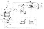
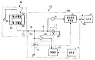
- FIG. 1 is a block diagram showing the overall configuration of the ultrasonic diagnostic apparatus of the present embodiment.
- the ultrasonic diagnostic apparatus 1 is connectable with an ultrasonic probe 2X having a capacitive ultrasonic transducer (c-MUT element) 2 and this ultrasonic probe 2X.
- the ultrasonic observation apparatus 3 that drives the c-MUT element 2 and receives the echo signal obtained by the c-MUT element 2, and the ultrasonic image data output from the ultrasonic observation apparatus 3 are
- the monitor 4 is configured to display an ultrasonic tomographic image of a subject scanned with an ultrasonic beam by the c-MUT element 2 by being input.
- the c-MUT element 2 of the ultrasonic probe 2X is provided with a planar first electrode 2B on a silicon substrate 2A, and a predetermined cavity (cavity) 2C is formed so as to face the first electrode 2B.
- a planar second electrode 2 ⁇ / b> D is provided at a distance.
- the second electrode 2D has a membrane for transmitting an ultrasonic wave and detecting an echo signal.
- a DC bias voltage (hereinafter simply referred to as a bias voltage) from the ultrasonic observation device 3 and driving of an RF signal are applied to one first electrode 2B of the c-MUT element 2.
- a transmission signal as a signal is applied.
- the first electrode 2B is connected to the connection terminal 3a of the ultrasonic observation apparatus 3 by the signal line 12.
- the second electrode 2D is grounded.
- at least the c-MUT element 2 and the signal line 12 are provided in an insertion portion of the ultrasonic probe 2X having a bending portion and a flexible tube portion.
- the ultrasonic observation apparatus 3 includes a connection terminal 3a, a DC bias output unit 5, a bias component cut capacitor 6, a transmission signal output unit 7, a reception signal amplifier 8, a reception signal processing unit 9, and a control.
- the unit 10 and the operation unit 11 are included.
- connection terminal 3 a is connected to the DC bias output unit 5 through the signal line 13 and the transmission signal output unit 7 through the bias component cutting capacitor 6.
- the DC bias output unit 5 generates a bias voltage necessary for driving the c-MUT element 2, and the generated bias voltage is transmitted to the c-MUT element 2 via the signal line 13, the connection terminal 3 a, and the signal line 12. Output to the first electrode 2B.
- the DC bias output unit 5 is configured to be able to change the bias voltage applied to the c-MUT element 2. The other end of the DC bias output unit 5 is grounded.
- the transmission signal output unit 7 generates an RF signal necessary for driving the c-MUT element 2, that is, a transmission signal which is a drive signal, and the generated transmission signal is transmitted to the signal line 13, the connection terminal 3a, the signal Output to the first electrode 2 B of the c-MUT element 2 via the line 12.
- the other end of the transmission signal output unit 7 is grounded. Therefore, in the configuration shown in FIG. 1, the bias voltage and the transmission signal are applied to the first electrode 2B of the c-MUT element 2, and in this case, the bias voltage is superimposed on the transmission signal. It is applied in the form.
- the midpoint of the signal line 13 between the bias component cutting capacitor 6 and the transmission signal output unit 7 is connected to the reception signal processing unit 9 through the reception signal amplifier 8 by the signal line 13. .
- the bias component cutting capacitor 6 is provided between the DC bias output unit 5 and the transmission signal output unit 7.
- the bias component cutting capacitor 6 prevents the DC component of the bias voltage from entering the transmission / reception circuit system including the transmission signal output unit 7 and the reception signal processing unit 9.
- the received signal (echo signal) obtained by driving the c-MUT element 2 by applying the bias voltage and the transmission signal passes through the bias component cut capacitor 6 and is amplified by the reception signal amplifier 8 to be subjected to the reception signal processing. Input to the unit 9.
- the reception signal processing unit 9 performs signal processing on the input reception signal to generate ultrasonic image data, and outputs the generated ultrasonic data to the output terminal 3b.
- a monitor 4 is connected to the output terminal 3b via a signal line 14, and the ultrasonic image data output to the output terminal 3b is displayed on the monitor 4.
- an operation unit 11 is connected to the control unit 10.
- the operation unit 11 includes various operation keys including a freeze release key, a freeze key, and a transmission start / transmission stop key.
- the operation unit 11 is supplied with an instruction signal that is an operation signal generated by an operation using various operation keys of the operation unit 11.
- the operation unit 11 outputs to the control unit 10 an instruction signal for instructing release of freeze or start of freezing, an instruction signal for instructing start of transmission, an instruction signal for instructing stop of transmission, and the like.
- the control unit 10 can control the DC bias output unit 5, the transmission signal output unit 7, and the reception signal processing unit 9 based on the supplied instruction signal. That is, the control unit 10 controls the bias voltage applied to the c-MUT element 2 and the output (transmission) timing of the transmission signal and the processing timing of the reception signal obtained by the c-MUT element 2.
- the control unit 10 when an instruction signal instructing transmission start is input from the operation unit 11, the control unit 10 outputs a bias voltage, and then outputs a transmission signal.
- the DC bias output unit 5 and the transmission signal output unit stop the output of the bias voltage after stopping the output of the transmission signal when an instruction signal instructing the transmission stop is input from the operation unit 11. 7 is controlled.
- the control unit 10 controls the DC bias output unit 5 so as not to apply the bias voltage when the ultrasonic diagnostic apparatus 1 is turned on.
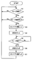
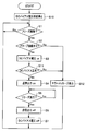
- FIG. 2 is a flowchart showing a specific control example of the control unit 10 when the apparatus is started.
- a power switch (not shown) is turned on and turned on in order to diagnose and examine a subject using the ultrasonic diagnostic apparatus of the present embodiment.
- control unit 10 of the ultrasonic diagnostic apparatus 1 reads out and executes a program for performing the processing shown in FIG. 2 from a memory (not shown) by the control unit 10 after power activation, and simultaneously executes the freeze mode. Control.
- the control unit 10 controls the DC bias output unit 5 so that a bias voltage is not applied to the c-MUT element 2 when the ultrasonic diagnostic apparatus 1 is powered on.
- the freeze release key of the operation unit 11 is determined based on the instruction signal supplied from the operation unit 11 in the determination process of step S1. It is determined whether or not the freeze mode is canceled by an operation (or a freeze key operation).
- control unit 10 When the freeze mode is instructed by the operation of the operation unit 11, the control unit 10 confirms that the c-MUT element 2 is connected in the subsequent step S2, and then performs the c-MUT element 2 in the process of step S3. Then, the DC bias output unit 5 is controlled so as to output the bias voltage, and then the transmission signal output unit 7 is controlled so as to output the transmission signal in the process of step S4.
- the determination of whether or not the c-MUT element 2 is connected in the step S2 is performed by, for example, detecting a current value flowing through the c-MUT element 2 and determining the presence or absence of connection based on the detection result, or c-MUT
- the element 2 may be assembled in the form of an ultrasonic probe, and a connector pin for connecting to the device may be provided on the probe, and a known technique or the like that determines the presence or absence of connection based on the open / short state of this pin may be used.
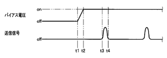
- Fig. 3 shows changes in bias voltage and transmission signal after such power-on.
- the bias voltage shown in FIG. 3 indicates the bias voltage that is the output of the DC bias output unit 5
- the transmission signal shown in FIG. 3 indicates the transmission signal that is the output of the transmission signal output unit 7
- FIG. A signal line 12 shown in FIG. 2 indicates a superimposed signal applied via the signal line 12 connected to the c-MUT element 2.
- the control unit 10 turns on the DC bias output unit 5. Then, as shown in the bias voltage of FIG. 3, the DC bias output unit 5 gradually increases the bias voltage value from time t1 to time t2, and reaches a predetermined value set in advance at time t2. The bias voltage is output so that
- the level change of the signal applied via the signal line 12 connected to the first electrode 2B of the c-MUT element 2 is as shown by the signal line 12 in FIG. Further, the voltage rises from the zero line to the bias voltage BV that is increased by the same voltage as the increase of the bias voltage (see the bias voltage in FIG. 3).
- the transmission signal output unit 7 outputs the transmission signal at a timing such that it rises at time t3 and falls at time t4, as shown in the transmission signal of FIG. To do.
- the received echo signal which is a received signal, is converted into ultrasonic image data by being processed by the received signal processing unit 9 of the ultrasonic observation device 3 and then displayed on the monitor 4.
- control unit 10 performs the determination process in the subsequent step S5 while the output of the transmission signal in the process in the step S4 is continued.
- determination process of step S5 based on the instruction signal supplied from the operation unit 11, it is determined whether a freeze mode execution request has been made by operating the freeze key of the operation unit 11.
- control unit 10 controls the transmission signal output unit 7 to stop outputting the transmission signal in the subsequent step S6, and then in step S7.
- the DC bias output unit 5 is controlled to stop the output of the bias voltage output to the c-MUT element 2 in the process.
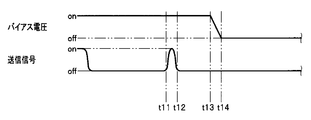
- Fig. 4 shows changes in bias voltage and transmission signal after execution of such freeze mode.
- the bias voltage shown in FIG. 4 indicates the bias voltage that is the output of the DC bias output unit 5
- the transmission signal shown in FIG. 4 indicates the transmission signal that is the output of the transmission signal output unit 7
- FIG. A signal line 12 shown in FIG. 2 indicates a superimposed signal applied via the signal line 12 connected to the c-MUT element 2.
- the transmission signal output unit 7 is controlled to stop the output of the output transmission signal by the process of step S6. The Then, after this time t13, as shown in the transmission signal of FIG. 4, the transmission signal is not output.
- the DC bias output unit 5 is turned off at time t13 by the process of step S7. Then, as shown in the bias voltage of FIG. 4, the DC bias output unit 5 gradually decreases the bias voltage BV from time t13 to time t14 and becomes zero at time t14. Stops (turns off) voltage output.
- the level change of the signal applied via the signal line 12 connected to the first electrode 2B of the c-MUT element 2 is as shown by the signal line 12 in FIG.
- the transmission signal (see the transmission signal in FIG. 4) superimposed on the bias voltage disappears, and the bias voltage disappears such that the superimposed bias voltage drops by BV to zero.
- control unit 10 executes the freeze mode, and thereafter, returns the process to step S1 and continues the determination process of step S1 again.
- the control unit 10 when the freeze mode is released, the control unit 10 outputs a transmission signal after applying a bias voltage, and when the freeze mode is executed, the reverse of the release of the freeze mode is performed. In the procedure, stop the transmission signal and then stop the output of the bias voltage. In other words, such a processing procedure by the control unit 10 can prevent a transmission signal from being output without applying a DC bias voltage to the c-MUT element 2.
- a transmission signal having both positive and negative polarities is not transmitted to the c-MUT element 2 without applying a bias voltage. Damage to the c-MUT element 2 can be prevented.
- FIG. 5 is a block diagram showing the overall configuration of an ultrasonic diagnostic apparatus according to the second embodiment of the present invention.
- the same components as those of the ultrasonic diagnostic apparatus according to the first embodiment are denoted by the same reference numerals, description thereof is omitted, and only different portions are described.
- the bias voltage and the transmission signal are applied to one electrode of the c-MUT element 2, that is, the first electrode 2B.
- the ultrasonic diagnostic apparatus 1A according to the embodiment is configured to supply a bias voltage to the first electrode 2B of the c-MUT element 2 and supply a transmission signal to the second electrode 2D.
- the configuration in which the electrode for supplying the bias voltage to the c-MUT element 2 and the electrode for supplying the transmission signal are different can be applied as in the first embodiment.
- An ultrasonic diagnostic apparatus 1A includes the same components as those in the first embodiment, that is, an ultrasonic probe 2X having a c-MUT element 2, an ultrasonic observation apparatus 3A, However, the connection configuration between the c-MUT element 2 of the ultrasonic probe 2X and the ultrasonic observation device 3A is different from the internal configuration of the ultrasonic observation device 3A.
- a bias voltage from the ultrasonic observation device 3 is applied to one first electrode 2B of the c-MUT element 2, and the other second electrode 2D is applied to the other second electrode 2D.
- the transmission signal is applied.
- the first electrode 2B is connected to the connection terminal 3a of the ultrasonic observation apparatus 3 by the signal line 12.
- the second electrode 2D is connected to the connection terminal 3c of the ultrasonic observation device 3 by a newly provided signal line 15.
- the ultrasonic observation apparatus 3A is configured to include the same components as those of the first embodiment, but is configured by newly providing the connection terminal 3c as described above.
- connection terminal 3 a is connected to the DC bias output unit 5 through the signal line 13.
- connection terminal 3c is connected to the reception signal processing unit 9 and the transmission signal output unit 7 via the signal line 13A and the reception signal amplifier 8.
- the DC bias output unit 5 generates a bias voltage necessary for driving the c-MUT element 2, and the generated bias voltage is transmitted to the c-MUT element 2 via the signal line 13, the connection terminal 3 a, and the signal line 12. Output to the first electrode 2B.
- the transmission signal output unit 7 generates an RF signal necessary for driving the c-MUT element 2, that is, a transmission signal as a drive signal, and the generated transmission signal is transmitted to the signal line 13A, the connection terminal 3c, the signal This is output to the second electrode 2D of the c-MUT element 2 via the line 15.
- a transmission signal is applied to the second electrode 2D side while a bias voltage is applied from the first electrode 2B side of the c-MUT element 2.
- the obtained echo signal (reception signal) is amplified by the reception signal amplifier 8 and input to the reception signal processing unit 9.
- the reception signal processing unit 9 performs signal processing on the input reception signal to generate ultrasonic image data, and outputs the generated ultrasonic image data to the output terminal 3b.
- a monitor 4 is connected to the output terminal 3b via a signal line 14, and the ultrasonic image data output to the output terminal 3b is displayed on the monitor 4.
- the bias voltage applied to the c-MUT element 2 and the output timing of the transmission signal are controlled by the control unit 10.
- the control unit 10 is connected to the operation unit 11 as in the first embodiment.
- the control unit 10 is configured to output the DC bias output unit 5 and the transmission signal based on the supplied instruction signal.
- the output unit 7 and the received signal processing unit 9 are controlled.
- control unit 10 transmits the bias voltage applied to the c-MUT element 2 and the transmission timing of the transmission signal and the received signal obtained by the c-MUT element 2. Control processing timing.
- the bias voltage applied to the c-MUT element 2 and the transmission timing of the transmission signal are controlled by the control unit 10 as in the first embodiment.
- FIG. 6 shows changes in bias voltage and transmission signal after power-on in FIG.
- the waveform of the bias voltage supply signal line 12 supplied to the first electrode 2B of the c-MUT element 2 is set to the bias voltage of FIG. 6, while the transmission / reception signal supplied to the second electrode 2D of the c-MUT element 2
- the waveform of the signal line 15 is shown in the transmission signal of FIG.
- the control unit 10 turns on the DC bias output unit 5 in step S3.
- the output is performed so that a predetermined bias voltage set in advance from time t1 to time t2 is obtained.
- a transmission signal that rises at time t3 and falls at time t4 is output.
- the first electrode 2B of the c-MUT element 2 even when the bias voltage is supplied to the first electrode 2B of the c-MUT element 2 and the transmission signal is supplied to the second electrode 2D, the first electrode Similarly to the embodiment, since no transmission signal is transmitted to the c-MUT element 2 without applying a bias voltage, the c-MUT element 2 can be prevented from being damaged.
- FIG. 8 and 9 relate to a third embodiment of the present invention
- FIG. 8 is a block diagram showing the overall configuration of an ultrasonic diagnostic apparatus according to the third embodiment
- FIG. 9 is a control of FIG. It is a flowchart which shows the example of control of a part.
- the same components and the same processes as those of the ultrasonic diagnostic apparatus of the first embodiment are denoted by the same reference numerals and step S numbers. Therefore, only the different parts will be described.
- the bias voltage is applied regardless of the operation state of the c-MUT element 2 that is the supply destination. There is a possibility that a load is applied to the circuit side of the observation devices 3 and 3A.
- the ultrasonic diagnostic apparatus 1B monitors the bias voltage applied to the c-MUT element 2 in order to prevent a load from being applied to the circuit side of the ultrasonic observation apparatus 3B.
- the detection unit 20 is provided and configured.
- the ultrasonic diagnostic apparatus 1B of the present embodiment shown in FIG. 8 includes the same components as the first embodiment, that is, an ultrasonic probe 2X having a c-MUT element 2, an ultrasonic observation apparatus 3A,
- the bias voltage detector 20 is provided inside the ultrasonic observation apparatus 3A.
- the configuration other than the bias voltage detection unit 20 is the same as that of the first embodiment. That is, the c-MUT element 2 and the ultrasonic observation apparatus 3B are configured in the same manner as the first embodiment and are connected in the same manner.
- the input terminal of the bias voltage detection unit 20 is connected to the output terminal of the DC bias output unit 5 as shown in FIG. 8, and the output terminal of the bias voltage detection unit 20 is connected to the output terminal. Connected to the control unit 10.
- the bias voltage detection unit 20 detects a bias voltage value that is an output of the DC bias output unit 5 and outputs the detected bias voltage value to the control unit 10.
- control unit 10 controls the bias voltage applied to the c-MUT element 2 and the output timing of the transmission signal to be the same timing as in the first embodiment. Be controlled.
- the control unit 10 has a memory (not shown) therein, and a preset DC bias voltage specified value (threshold value) is stored in the memory.
- This DC bias voltage specified value is a voltage value suitable for the normal operation of the c-MUT element 2.
- the DC bias voltage prescribed value can be freely set and changed according to the type of the c-MUT element 2 to be used.
- control unit 10 applies the detection result from the bias voltage detection unit 20 and the bias voltage for normal operation while applying a DC bias voltage to the c-MUT element 2.
- a comparison with a specified value is performed, and when the detection result from the bias voltage detection unit 20 exceeds the specified bias voltage value, control is performed such that an error message indicating this is displayed on the monitor 4. In this way, it is monitored that a normal DC bias voltage is output to the c-MUT element 2.
- FIG. 9 is a flowchart showing a specific control example of the control unit 10 at the time of starting the apparatus in the present embodiment.
- the control unit 10 of the ultrasonic diagnostic apparatus 1B reads and executes a program for performing the processing shown in FIG. 9 from a memory (not shown) by the control unit 10 after the power is turned on, and simultaneously executes the freeze mode. Control.
- the control unit 10 controls the DC bias output unit 5 so that the bias voltage is not applied to the c-MUT element 2 by the process of step S10 when the ultrasonic diagnostic apparatus 1 is powered on.
- control unit 10 operates the freeze release key (or freeze) of the operation unit 11 based on the instruction signal supplied from the operation unit 11 in the determination process of step S1. It is determined whether the freeze mode is canceled by the key operation).
- control unit 10 When the freeze mode is instructed by the operation of the operation unit 11, the control unit 10 confirms that the c-MUT element 2 is connected in the subsequent step S2, and then performs the c-MUT element 2 in the process of step S3.
- the DC bias output unit 5 is controlled so as to output the bias voltage at the same time, and then the process proceeds to the determination process of step S11.
- step S2 If it is determined in step S2 that the c-MUT element 2 is not connected, the control unit 10 displays a display indicating that the c-MUT element 2 is not connected in the subsequent step S12. After the display on the screen of the monitor 4, the process returns to step S1.
- the ultrasonic diagnostic apparatus can also connect a piezoelectric ultrasonic transducer other than the c-MUT element 2. Therefore, it is detected whether the c-MUT element 2 or the piezoelectric ultrasonic transducer is connected in the process of step S2, and any ultrasonic transducer is detected in the process of step S12.
- a connection state indicating whether it is connected may be displayed on the screen of the monitor 4.
- control unit 10 compares the detection result from the bias voltage detection unit 20 with the specified bias voltage value for normal operation, and detects from the bias voltage detection unit 20. Determine whether the result is normal.
- the detection result from the bias voltage detector 20 is equal to or less than the specified bias voltage value, it is determined to be normal, and conversely, if it exceeds, it is determined to be not normal.
- the control unit 10 determines that the DC bias voltage is larger than the specified bias voltage and is normal in the process of step S12. After controlling to display an error message or the like indicating that the value is not a value on the screen of the monitor 4, the process returns to step S1.
- control unit 10 controls the transmission signal output unit 7 so as to output the transmission signal in the process of step S4. .
- control part 10 performs the judgment process by following step S5, while the output of the transmission signal by the process of the said step S4 is continued.
- determination process of step S5 based on the instruction signal supplied from the operation unit 11, it is determined whether a freeze mode execution request has been made by operating the freeze key of the operation unit 11.
- control unit 10 controls the transmission signal output unit 7 to stop outputting the transmission signal in the subsequent step S6, and then in step S7.
- the DC bias output unit 5 is controlled to stop the output of the bias voltage output to the c-MUT element 2 in the process.
- bias voltage applied to the c-MUT element 2 and the output timing of the transmission signal are controlled in the same manner as in the first embodiment.
- control unit 10 executes the freeze mode, and thereafter, returns the process to step S1 and continues the determination process of step S1 again.
- the DC bias voltage detection unit 20 generates ultrasonic waves by the c-MUT element 2 in addition to applying the bias voltage to the c-MUT element 2. It may be operated during (scanning). As a result, when the DC bias voltage exceeds the specified bias voltage or becomes different from the set value, an error message is displayed on the screen of the monitor 4 and, similar to the freeze mode request, after the transmission output is stopped, the DC bias is displayed.
- the freeze mode may be executed by a control procedure in which the voltage is lowered and stopped.
- an error message or the like is displayed on the screen of the monitor 4 based on the comparison result between the detection result from the DC bias voltage detection unit 20 and the specified bias voltage value. It is not limited to.
- the control unit 10 controls the output state of the bias voltage by the DC bias output unit 5 to always be displayed on the screen of the monitor 4 based on the detection result from the DC bias voltage detection unit 20, The bias voltage applied to the c-MUT element 2 may be monitored.
- the bias voltage detection unit 20 for monitoring the bias voltage applied to the c-MUT element 2 is provided. With the configuration, it is possible to prevent a load from being applied to the circuit side of the ultrasonic observation apparatus 3B due to the application of the bias voltage.
Landscapes
- Health & Medical Sciences (AREA)
- Life Sciences & Earth Sciences (AREA)
- Engineering & Computer Science (AREA)
- Medical Informatics (AREA)
- Surgery (AREA)
- Pathology (AREA)
- Radiology & Medical Imaging (AREA)
- Biophysics (AREA)
- Biomedical Technology (AREA)
- Heart & Thoracic Surgery (AREA)
- Physics & Mathematics (AREA)
- Molecular Biology (AREA)
- Nuclear Medicine, Radiotherapy & Molecular Imaging (AREA)
- Animal Behavior & Ethology (AREA)
- General Health & Medical Sciences (AREA)
- Public Health (AREA)
- Veterinary Medicine (AREA)
- Mechanical Engineering (AREA)
- Gynecology & Obstetrics (AREA)
- Computer Networks & Wireless Communication (AREA)
- Ultra Sonic Daignosis Equipment (AREA)
Abstract
Disclosed is an ultrasonic diagnostic device (1) which can be connected to an ultrasonic probe (2X) having a c-MUT element (2), the sensitivity of which can be controlled in correspondence with the bias voltage applied. The ultrasonic diagnostic device (1) has a DC bias output unit (5), a transmission signal output unit (7), an operation unit (11), and a control unit (10). The control unit (10) controls the DC bias output unit (5) and the transmission signal output unit (7) so that when a command signal which commands transmission initiation is input from the operation unit (11), an ultrasonic transmission signal is output after the application of a bias voltage, and when a command signal which commands transmission cessation is input from the operation unit (11), the application of the bias voltage is stopped after the output of the ultrasonic transmission signal is stopped.
Description
本発明は、静電容量型超音波振動子を有する超音波プローブを接続可能な超音波診断装置に関する。
The present invention relates to an ultrasonic diagnostic apparatus to which an ultrasonic probe having a capacitive ultrasonic transducer can be connected.
従来、超音波振動子では、電気信号を超音波に変換させる圧電素子としてセラミック圧電材PZT(ジルコン酸チタン酸鉛)が使用されてきたが、シリコンマイクロマシーニング技術を用いてシリコン半導体基板を加工した静電容量型超音波振動子(Capacitive Micro-Machined Ultrasonic Transducer(以下、c-MUT素子と称す))が注目を集めている。
Conventionally, in an ultrasonic transducer, a ceramic piezoelectric material PZT (lead zirconate titanate) has been used as a piezoelectric element for converting an electrical signal into an ultrasonic wave, but a silicon semiconductor substrate is processed using silicon micromachining technology. Capacitive ultrasonic transducers (Capacitive Micro-Machined Ultrasonic Transducer (hereinafter referred to as c-MUT element)) are attracting attention.
このc-MUT素子は、シリコン基板上に平面状の第1の電極を設けるとともに、この第1の電極に対向するように所定の空洞(キャビティ)を隔てて平面状の第2の電極を設けて構成されている。
In this c-MUT element, a planar first electrode is provided on a silicon substrate, and a planar second electrode is provided with a predetermined cavity (cavity) so as to face the first electrode. Configured.
前記c-MUT素子を有する超音波プローブを用いて超音波診断画像を生成する超音波診断装置においては、前記c-MUT素子は、前記2つの電極間にバイアス電圧を印加しつつ、一方の電極に駆動信号を印加することで、空洞上部の膜(第2の電極を構成するメンブレン)をゆらせて超音波を送信し、帰ってきたエコー信号を、前記空洞上部の膜で検出するようにして超音波の送受信を行っている。
In an ultrasonic diagnostic apparatus that generates an ultrasonic diagnostic image using an ultrasonic probe having the c-MUT element, the c-MUT element applies a bias voltage between the two electrodes while one electrode By applying a drive signal to the membrane, the membrane at the top of the cavity (the membrane that constitutes the second electrode) is swayed and ultrasonic waves are transmitted, and the echo signal that is returned is detected by the membrane at the top of the cavity. To send and receive ultrasound.
つまり、前記c-MUT素子は、超音波を発生するためのRF信号である駆動信号だけでなくてバイアス電圧が送信時、受信時ともに必要とされている。そのため、前記c-MUT素子は、印加するバイアスレベルを変化させることで感度を制御できる。
That is, the c-MUT element is required not only for a drive signal which is an RF signal for generating an ultrasonic wave but also for a bias voltage when transmitting and receiving. Therefore, the sensitivity of the c-MUT element can be controlled by changing the applied bias level.
しかしながら、c-MUT素子への過度のバイアス電圧の印加は、該c-MUT素子において短絡状態を引き起こし、結果として過電流状態となりc-MUT素子の破損につながってしまう。
However, application of an excessive bias voltage to the c-MUT element causes a short circuit state in the c-MUT element, resulting in an overcurrent state and leading to damage of the c-MUT element.
このような、過度のバイアス電圧の印加によるc-MUT素子の破損を防ぐために、過電圧検出手段をc-MUT素子側の電極とバイアス電源との間に設け、該過電圧検出手段により過度のバイアス電圧の印加を検出したときにはバイアス電圧の印加を停止するようにしている(例えば、特開2007-29259号公報参照)。
In order to prevent such damage to the c-MUT element due to application of an excessive bias voltage, an overvoltage detection means is provided between the electrode on the c-MUT element side and the bias power supply, and the overvoltage detection means causes an excessive bias voltage. When application of the bias is detected, application of the bias voltage is stopped (see, for example, Japanese Patent Application Laid-Open No. 2007-29259).
また、c-MUT素子の電極間に印加するバイアス電圧の大きさが所定の範囲を超えると、電極間に挟み込まれた太鼓状の犠牲層が潰れた状態、すなわち、Collapse状態となる。このCollapse状態時に、被検体に超音波の過大出力を防止するために、DCバイアス電圧を検出し、検出されたDCバイアス電圧が閾値を超えると、スイッチによって、DCバイアス回路と超音波振動子との電気的接続を遮断するように構成した保護回路を有する超音波振動子及び超音波診断装置がある(例えば、特開2008-136725号公報参照)。
In addition, when the magnitude of the bias voltage applied between the electrodes of the c-MUT element exceeds a predetermined range, the drum-shaped sacrificial layer sandwiched between the electrodes enters a collapsed state, that is, a Collapse state. In this Collapse state, in order to prevent an excessive output of ultrasonic waves to the subject, a DC bias voltage is detected, and when the detected DC bias voltage exceeds a threshold value, the switch causes the DC bias circuit and the ultrasonic transducer to be There is an ultrasonic transducer and an ultrasonic diagnostic apparatus having a protection circuit configured to cut off the electrical connection (see, for example, JP-A-2008-136725).
また、他の従来技術としては、例えば、国際公開第2005/120130号に示すように、送信時に、着脱式超音波プローブの超音波振動子に、RF信号、つまり駆動信号をDCバイアス発生回路から出力されるDCバイアス電圧に重畳する超音波プローブ装置がある。
As another conventional technique, for example, as shown in International Publication No. 2005/120130, an RF signal, that is, a drive signal is transmitted from a DC bias generation circuit to an ultrasonic transducer of a detachable ultrasonic probe at the time of transmission. There is an ultrasonic probe device that superimposes on an output DC bias voltage.
しかしながら、特開2007-29259号公報及び特開2008-136725号公報の従来技術では、c-MUT素子に、バイアス電圧を印加しない状態で、正負の両極性の駆動信号を送信した場合、過電圧検出手段及び保護回路等の保護手段を設けているにも拘わらず、c-MUT素子が破損してしまう虞れがある。
However, in the prior art disclosed in Japanese Patent Application Laid-Open No. 2007-29259 and Japanese Patent Application Laid-Open No. 2008-136725, when a positive and negative drive signal is transmitted to the c-MUT element without applying a bias voltage, overvoltage detection is performed. In spite of the provision of protection means such as the protection means and the protection circuit, the c-MUT element may be damaged.
また、国際公開第2005/120130号に記載の超音波プローブにおいても、このような問題が生じてしまう虞れがある。
Also, the ultrasonic probe described in International Publication No. 2005/120130 may cause such a problem.
そこで、本発明は前記問題点に鑑みてなされたもので、c-MUT素子の破損を防止することができる超音波診断装置を提供することを目的とする。
Therefore, the present invention has been made in view of the above problems, and an object thereof is to provide an ultrasonic diagnostic apparatus capable of preventing the c-MUT element from being damaged.
本発明の超音波診断装置は、印加するバイアス電圧に応じて感度の制御が可能な静電容量型超音波振動子を有する超音波プローブを接続可能な超音波診断装置において、前記静電容量型超音波振動子に印加する前記バイアス電圧を可変可能なバイアス電圧出力部と、前記静電容量型超音波振動子に超音波送信信号を出力する送信信号出力部と、前記バイアス電圧出力部と前記送信信号出力部とを含む前記超音波診断装置を指示する指示信号を出力する操作部と、前記操作部からの指示信号に基づいて、前記バイアス電圧及び前記送信信号の出力タイミングを制御するもので、前記バイアス電圧を出力してから前記超音波信号を出力し、或いは前記超音波信号の出力を停止してから前記バイアス電圧の出力を停止するように前記バイアス電圧出力部と前記送信信号出力部とを制御する制御部と、を具備したことを特徴とする。
The ultrasonic diagnostic apparatus of the present invention is an ultrasonic diagnostic apparatus capable of connecting an ultrasonic probe having a capacitive ultrasonic transducer capable of controlling sensitivity in accordance with an applied bias voltage. A bias voltage output unit capable of changing the bias voltage applied to the ultrasonic transducer; a transmission signal output unit that outputs an ultrasonic transmission signal to the capacitive ultrasonic transducer; the bias voltage output unit; An operation unit for outputting an instruction signal for instructing the ultrasonic diagnostic apparatus including a transmission signal output unit; and an output timing of the bias voltage and the transmission signal based on the instruction signal from the operation unit. The bias voltage is outputted so that the ultrasonic signal is outputted after the bias voltage is outputted, or the output of the bias voltage is stopped after the output of the ultrasonic signal is stopped. Characterized by comprising a control unit for controlling the force unit and the transmission signal output portion.
以下、図面を参照しながら本発明の実施の形態について詳細に説明する。
Hereinafter, embodiments of the present invention will be described in detail with reference to the drawings.
(第1の実施の形態)
図1から図4は本発明の第1の実施の形態に係り、図1は本実施の形態の超音波診断装置の全体構成を示すブロック図である。 (First embodiment)
1 to 4 relate to the first embodiment of the present invention, and FIG. 1 is a block diagram showing the overall configuration of the ultrasonic diagnostic apparatus of the present embodiment.
図1から図4は本発明の第1の実施の形態に係り、図1は本実施の形態の超音波診断装置の全体構成を示すブロック図である。 (First embodiment)
1 to 4 relate to the first embodiment of the present invention, and FIG. 1 is a block diagram showing the overall configuration of the ultrasonic diagnostic apparatus of the present embodiment.
図1に示す本実施の形態に係る超音波診断装置1は、静電容量型超音波振動子(c-MUT素子)2を有する超音波プローブ2Xと、この超音波プローブ2Xが接続可能であり、前記c-MUT素子2を駆動するとともにこのc-MUT素子2により得られたエコー信号の受信処理を行う超音波観測装置3と、この超音波観測装置3から出力される超音波画像データが入力されることにより、c-MUT素子2により超音波ビームで走査した被検体の超音波断層像を表示するモニタ4とを有して構成される。
The ultrasonic diagnostic apparatus 1 according to the present embodiment shown in FIG. 1 is connectable with an ultrasonic probe 2X having a capacitive ultrasonic transducer (c-MUT element) 2 and this ultrasonic probe 2X. The ultrasonic observation apparatus 3 that drives the c-MUT element 2 and receives the echo signal obtained by the c-MUT element 2, and the ultrasonic image data output from the ultrasonic observation apparatus 3 are The monitor 4 is configured to display an ultrasonic tomographic image of a subject scanned with an ultrasonic beam by the c-MUT element 2 by being input.
前記超音波プローブ2Xのc-MUT素子2は、シリコン基板2A上に平面状の第1の電極2Bを設けるとともに、この第1の電極2Bに対向するように、所定の空洞(キャビティ)2Cを隔てて平面状の第2の電極2Dを設けて構成されている。なお、図示はしないが、前記第2の電極2Dは、超音波を送信するとともにエコー信号を検出するためのメンブレンを有して構成されている。
The c-MUT element 2 of the ultrasonic probe 2X is provided with a planar first electrode 2B on a silicon substrate 2A, and a predetermined cavity (cavity) 2C is formed so as to face the first electrode 2B. A planar second electrode 2 </ b> D is provided at a distance. Although not shown, the second electrode 2D has a membrane for transmitting an ultrasonic wave and detecting an echo signal.
そして、図1に示す構成では、前記c-MUT素子2の一方の第1の電極2Bに、前記超音波観測装置3からのDCバイアス電圧(以下、単にバイアス電圧と称す)とRF信号の駆動信号である送信信号とが印加されるようになっている。
In the configuration shown in FIG. 1, a DC bias voltage (hereinafter simply referred to as a bias voltage) from the ultrasonic observation device 3 and driving of an RF signal are applied to one first electrode 2B of the c-MUT element 2. A transmission signal as a signal is applied.
つまり、前記第1の電極2Bは、信号線12によって前記超音波観測装置3の接続端子3aに接続されている。また、前記第2の電極2Dは、接地している。なお、少なくとも前記c-MUT素子2及び信号線12は、図示はしないが前記超音波プローブ2Xの、湾曲部及び可撓管部を有する挿入部内に設けられている。
That is, the first electrode 2B is connected to the connection terminal 3a of the ultrasonic observation apparatus 3 by the signal line 12. The second electrode 2D is grounded. Although not shown, at least the c-MUT element 2 and the signal line 12 are provided in an insertion portion of the ultrasonic probe 2X having a bending portion and a flexible tube portion.
超音波観測装置3は、前記接続端子3aと、DCバイアス出力部5と、バイアス成分カット用コンデンサ6と、送信信号出力部7と、受信信号用アンプ8と、受信信号処理部9と、制御部10と、操作部11と、を有して構成されている。
The ultrasonic observation apparatus 3 includes a connection terminal 3a, a DC bias output unit 5, a bias component cut capacitor 6, a transmission signal output unit 7, a reception signal amplifier 8, a reception signal processing unit 9, and a control. The unit 10 and the operation unit 11 are included.
前記超音波観測装置3の内部において、前記接続端子3aは、信号線13を介してDCバイアス出力部5と、バイアス成分カット用コンデンサ6を介して送信信号出力部7とに接続される。
In the ultrasonic observation apparatus 3, the connection terminal 3 a is connected to the DC bias output unit 5 through the signal line 13 and the transmission signal output unit 7 through the bias component cutting capacitor 6.
DCバイアス出力部5は、前記c-MUT素子2の駆動に必要なバイアス電圧を生成し、この生成したバイアス電圧を、信号線13、接続端子3a、信号線12を介してc-MUT素子2の第1の電極2Bに出力する。このDCバイアス出力部5は、c-MUT素子2に印加する前記バイアス電圧を可変可能に構成される。なお、DCバイアス出力部5の他端は接地している。
The DC bias output unit 5 generates a bias voltage necessary for driving the c-MUT element 2, and the generated bias voltage is transmitted to the c-MUT element 2 via the signal line 13, the connection terminal 3 a, and the signal line 12. Output to the first electrode 2B. The DC bias output unit 5 is configured to be able to change the bias voltage applied to the c-MUT element 2. The other end of the DC bias output unit 5 is grounded.
また、送信信号出力部7は、前記c-MUT素子2の駆動に必要なRF信号、つまり駆動信号である送信信号を生成し、この生成した送信信号を、信号線13、接続端子3a、信号線12を介してc-MUT素子2の第1の電極2Bに出力する。なお、送信信号出力部7の他端は接地している。
従って、図1に示す構成では、c-MUT素子2の第1の電極2Bに、バイアス電圧と送信信号とが印加されるようになっており、またこの場合、バイアス電圧が送信信号に重畳された形で印加されるようになっている。 The transmissionsignal output unit 7 generates an RF signal necessary for driving the c-MUT element 2, that is, a transmission signal which is a drive signal, and the generated transmission signal is transmitted to the signal line 13, the connection terminal 3a, the signal Output to the first electrode 2 B of the c-MUT element 2 via the line 12. The other end of the transmission signal output unit 7 is grounded.
Therefore, in the configuration shown in FIG. 1, the bias voltage and the transmission signal are applied to thefirst electrode 2B of the c-MUT element 2, and in this case, the bias voltage is superimposed on the transmission signal. It is applied in the form.
従って、図1に示す構成では、c-MUT素子2の第1の電極2Bに、バイアス電圧と送信信号とが印加されるようになっており、またこの場合、バイアス電圧が送信信号に重畳された形で印加されるようになっている。 The transmission
Therefore, in the configuration shown in FIG. 1, the bias voltage and the transmission signal are applied to the
また、前記バイアス成分カット用コンデンサ6と送信信号出力部7との間の信号線13の中点は、該信号線13により、受信信号用アンプ8を介して受信信号処理部9に接続される。
The midpoint of the signal line 13 between the bias component cutting capacitor 6 and the transmission signal output unit 7 is connected to the reception signal processing unit 9 through the reception signal amplifier 8 by the signal line 13. .
バイアス成分カット用コンデンサ6は、前記DCバイアス出力部5と前記送信信号出力部7との間に設けられている。そして、このバイアス成分カット用コンデンサ6は、バイアス電圧のDC成分が前記送信信号出力部7及び受信信号処理部9を含む送受信回路系に侵入しないようにする。
The bias component cutting capacitor 6 is provided between the DC bias output unit 5 and the transmission signal output unit 7. The bias component cutting capacitor 6 prevents the DC component of the bias voltage from entering the transmission / reception circuit system including the transmission signal output unit 7 and the reception signal processing unit 9.
バイアス電圧及び送信信号の印加によるc-MUT素子2の駆動によって得られた受信号(エコー信号)は、バイアス成分カット用コンデンサ6を通り、受信信号用アンプ8によって増幅された後、受信信号処理部9に入力される。
The received signal (echo signal) obtained by driving the c-MUT element 2 by applying the bias voltage and the transmission signal passes through the bias component cut capacitor 6 and is amplified by the reception signal amplifier 8 to be subjected to the reception signal processing. Input to the unit 9.
受信信号処理部9は、入力された受信信号に信号処理を施して超音波画像データを生成し、生成した超音波データを出力端子3bに出力する。この出力端子3bには、信号線14を介してモニタ4が接続されており、出力端子3bに出力された超音波画像データは、該モニタ4によって表示される。
The reception signal processing unit 9 performs signal processing on the input reception signal to generate ultrasonic image data, and outputs the generated ultrasonic data to the output terminal 3b. A monitor 4 is connected to the output terminal 3b via a signal line 14, and the ultrasonic image data output to the output terminal 3b is displayed on the monitor 4.
また、前記制御部10には、操作部11が接続される。この操作部11は、例えば、フリーズ解除キーやフリーズキー、送信開始/送信停止キーを含む各種操作キーを有して構成される。そしてこの操作部11は、この操作部11の各種操作キーによる操作により生成された操作信号である指示信号が供給される。例えば、操作部11は、フリーズ解除又はフリーズ開始を指示する指示信号、送信開始を指示する指示信号、及び送信停止を指示する指示信号等を前記制御部10に出力する。
Further, an operation unit 11 is connected to the control unit 10. For example, the operation unit 11 includes various operation keys including a freeze release key, a freeze key, and a transmission start / transmission stop key. The operation unit 11 is supplied with an instruction signal that is an operation signal generated by an operation using various operation keys of the operation unit 11. For example, the operation unit 11 outputs to the control unit 10 an instruction signal for instructing release of freeze or start of freezing, an instruction signal for instructing start of transmission, an instruction signal for instructing stop of transmission, and the like.
前記制御部10は、この供給された指示信号に基づき、前記DCバイアス出力部5と、前記送信信号出力部7と、前記受信信号処理部9とを制御が可能である。つまり、制御部10は、c-MUT素子2に印加するバイアス電圧及び送信信号の出力(送信)タイミングと、該c-MUT素子2により得られた受信信号の処理のタイミングとを制御する。
The control unit 10 can control the DC bias output unit 5, the transmission signal output unit 7, and the reception signal processing unit 9 based on the supplied instruction signal. That is, the control unit 10 controls the bias voltage applied to the c-MUT element 2 and the output (transmission) timing of the transmission signal and the processing timing of the reception signal obtained by the c-MUT element 2.
次に、本実施の形態の超音波診断装置の作用について図2から図4を用いて説明する。
Next, the operation of the ultrasonic diagnostic apparatus according to the present embodiment will be described with reference to FIGS.
本実施の形態の超音波診断装置1では、前記制御部10は、前記操作部11から送信開始を指示する指示信号が入力された場合、バイアス電圧を出力した後、送信信号を出力し、前記操作部11から送信停止を指示する指示信号が入力された場合、前記送信信号の出力を停止してから、前記バイアス電圧の出力を停止するように前記DCバイアス出力部5及び前記送信信号出力部7を制御する。
In the ultrasonic diagnostic apparatus 1 according to the present embodiment, when an instruction signal instructing transmission start is input from the operation unit 11, the control unit 10 outputs a bias voltage, and then outputs a transmission signal. The DC bias output unit 5 and the transmission signal output unit stop the output of the bias voltage after stopping the output of the transmission signal when an instruction signal instructing the transmission stop is input from the operation unit 11. 7 is controlled.
また、前記制御部10は、超音波診断装置1の電源投入時に、前記バイアス電圧を印加しないように前記DCバイアス出力部5を制御する。
The control unit 10 controls the DC bias output unit 5 so as not to apply the bias voltage when the ultrasonic diagnostic apparatus 1 is turned on.
このような制御部10の装置起動時からの具体的な制御例を示すフローチャートを図2に示す。
FIG. 2 is a flowchart showing a specific control example of the control unit 10 when the apparatus is started.
いま、本実施の形態の超音波診断装置を用いて被検体の診断・診察を行うために図示しない電源スイッチをオンして電源を投入したとする。
Now, assume that a power switch (not shown) is turned on and turned on in order to diagnose and examine a subject using the ultrasonic diagnostic apparatus of the present embodiment.
すると、該超音波診断装置1の制御部10は、電源起動後、制御部10により図示しないメモリから図2に示す処理を行うためのプログラムを読み出して実行し、同時にフリーズモードを実行するように制御する。
Then, the control unit 10 of the ultrasonic diagnostic apparatus 1 reads out and executes a program for performing the processing shown in FIG. 2 from a memory (not shown) by the control unit 10 after power activation, and simultaneously executes the freeze mode. Control.
このとき、超音波観測装置3は、電源起動後、フリーズモードが実行されるので、DCバイアス出力部5からのバイアス電圧がc-MUT素子2に供給されない状態となる。すなわち、制御部10は、前記超音波診断装置1の電源投入時に、バイアス電圧をc-MUT素子2に印加しないようにDCバイアス出力部5を制御する。
At this time, since the ultrasound observation apparatus 3 is in the freeze mode after the power is turned on, the bias voltage from the DC bias output unit 5 is not supplied to the c-MUT element 2. That is, the control unit 10 controls the DC bias output unit 5 so that a bias voltage is not applied to the c-MUT element 2 when the ultrasonic diagnostic apparatus 1 is powered on.
そして、制御部10は、図2に示す処理を行うためのプログラムを実行すると、ステップS1の判断処理にて、操作部11から供給される指示信号に基づき、該操作部11のフリーズ解除キーの操作(或いはフリーズキーの操作であっても良い)によってフリーズモードが解除されたか否かを判断する。
Then, when the control unit 10 executes the program for performing the processing shown in FIG. 2, the freeze release key of the operation unit 11 is determined based on the instruction signal supplied from the operation unit 11 in the determination process of step S1. It is determined whether or not the freeze mode is canceled by an operation (or a freeze key operation).
操作部11の操作によってフリーズモード解除が指示された場合、制御部10は、続くステップS2でc-MUT素子2が接続されていることを確認した後、ステップS3の処理でc-MUT素子2にバイアス電圧を出力するようにDCバイアス出力部5を制御し、その後、ステップS4の処理で、送信信号を出力するように送信信号出力部7を制御する。
When the freeze mode is instructed by the operation of the operation unit 11, the control unit 10 confirms that the c-MUT element 2 is connected in the subsequent step S2, and then performs the c-MUT element 2 in the process of step S3. Then, the DC bias output unit 5 is controlled so as to output the bias voltage, and then the transmission signal output unit 7 is controlled so as to output the transmission signal in the process of step S4.
なお、前記ステップS2のc-MUT素子2の接続の有無の判断は、例えば、c-MUT素子2に流れる電流値を検出し、検出結果に基づき接続の有無を判断する、または、c-MUT素子2を超音波プローブ形状に組み付け、このプローブに装置と接続するコネクタピンを設け、このピンのオープン/ショート状態により接続の有無を判断するような公知の技術等を用いて行えば良い。
The determination of whether or not the c-MUT element 2 is connected in the step S2 is performed by, for example, detecting a current value flowing through the c-MUT element 2 and determining the presence or absence of connection based on the detection result, or c-MUT The element 2 may be assembled in the form of an ultrasonic probe, and a connector pin for connecting to the device may be provided on the probe, and a known technique or the like that determines the presence or absence of connection based on the open / short state of this pin may be used.
このような電源起動時以降のバイアス電圧、送信信号の変化を図3に示す。なお、図3において、図3に示すバイアス電圧はDCバイアス出力部5の出力であるバイアス電圧を示し、図3に示す送信信号は送信信号出力部7の出力である送信信号を示し、図3に示す信号線12はc-MUT素子2に接続した信号線12を介して印加する重畳信号を示している。
Fig. 3 shows changes in bias voltage and transmission signal after such power-on. 3, the bias voltage shown in FIG. 3 indicates the bias voltage that is the output of the DC bias output unit 5, the transmission signal shown in FIG. 3 indicates the transmission signal that is the output of the transmission signal output unit 7, and FIG. A signal line 12 shown in FIG. 2 indicates a superimposed signal applied via the signal line 12 connected to the c-MUT element 2.
図3に示すように、例えば時刻t1にてフリーズ解除がなされたとすると、制御部10により、DCバイアス出力部5がオンされる。すると、このDCバイアス出力部5は、図3のバイアス電圧に示すように、時刻t1から時刻t2までの間で、徐々にバイアス電圧値を上昇させ、時刻t2にて予め設定された所定値となるようにバイアス電圧を出力する。
As shown in FIG. 3, for example, if the freeze is released at time t1, the control unit 10 turns on the DC bias output unit 5. Then, as shown in the bias voltage of FIG. 3, the DC bias output unit 5 gradually increases the bias voltage value from time t1 to time t2, and reaches a predetermined value set in advance at time t2. The bias voltage is output so that
この時刻t1から時刻t2までの期間において、c-MUT素子2の第1の電極2Bに接続される信号線12を介して印加される信号のレベル変化は、図3の信号線12に示すように、ゼロのラインから、前記バイアス電圧の上昇分(図3のバイアス電圧参照)と同じ電圧分上昇したバイアス電圧分BVまで上昇する。
During the period from time t1 to time t2, the level change of the signal applied via the signal line 12 connected to the first electrode 2B of the c-MUT element 2 is as shown by the signal line 12 in FIG. Further, the voltage rises from the zero line to the bias voltage BV that is increased by the same voltage as the increase of the bias voltage (see the bias voltage in FIG. 3).
その後、前記ステップS4により送信信号を出力する場合、送信信号出力部7は、図3の送信信号に示すように、時刻t3にて立ち上がり、時刻t4にて立ち下がるようなタイミングで送信信号を出力する。
Thereafter, when the transmission signal is output in step S4, the transmission signal output unit 7 outputs the transmission signal at a timing such that it rises at time t3 and falls at time t4, as shown in the transmission signal of FIG. To do.
すると、このようなタイミングで送信信号を出力すると、前記信号線12には、図3の信号線12に示すように、時刻t3と時刻t4との間でバイアス電圧分BVに前記送信信号を重畳した形の送信信号が出力される。
Then, when the transmission signal is output at such timing, the transmission signal is superimposed on the bias voltage component BV between the time t3 and the time t4 on the signal line 12 as shown by the signal line 12 in FIG. A transmission signal of the form is output.
以降、このような図3の信号線12に示す送信信号が信号線12を介してc-MUT素子2に出力することにより、該c-MUT素子2は第2の電極2Dのメンブレンにより超音波を発生し、そして帰ってきたエコー信号を前記第2の電極2Dのメンブレンにより検出し、前記超音波観測装置3へと出力する。これにより、入力された受信信号であるエコー信号は、超音波観測装置3の受信信号処理部9によって処理されることにより超音波画像データに変換され、その後モニタ4によって表示される。
3 is output to the c-MUT element 2 via the signal line 12, so that the c-MUT element 2 is ultrasonicated by the membrane of the second electrode 2D. And the echo signal that has returned is detected by the membrane of the second electrode 2D and output to the ultrasonic observation apparatus 3. As a result, the received echo signal, which is a received signal, is converted into ultrasonic image data by being processed by the received signal processing unit 9 of the ultrasonic observation device 3 and then displayed on the monitor 4.
再び、図2に戻り、制御部10は、前記ステップS4の処理での送信信号の出力の継続中に、続くステップS5による判断処理を行う。このステップS5の判断処理では、操作部11から供給される指示信号に基づき、該操作部11のフリーズキーの操作によってフリーズモード実行の要求があったか否かを判断する。
2 again, the control unit 10 performs the determination process in the subsequent step S5 while the output of the transmission signal in the process in the step S4 is continued. In the determination process of step S5, based on the instruction signal supplied from the operation unit 11, it is determined whether a freeze mode execution request has been made by operating the freeze key of the operation unit 11.
操作部11の操作によってフリーズモード実行の要求の指示があった場合、制御部10は、続くステップS6で送信信号の出力を停止するように送信信号出力部7を制御し、その後、ステップS7の処理でc-MUT素子2に出力しているバイアス電圧の出力を停止するようにDCバイアス出力部5を制御する。
When there is an instruction to execute the freeze mode by operating the operation unit 11, the control unit 10 controls the transmission signal output unit 7 to stop outputting the transmission signal in the subsequent step S6, and then in step S7. The DC bias output unit 5 is controlled to stop the output of the bias voltage output to the c-MUT element 2 in the process.
このようなフリーズモード実行時以降のバイアス電圧、送信信号の変化を図4に示す。なお、図4において、図4に示すバイアス電圧はDCバイアス出力部5の出力であるバイアス電圧を示し、図4に示す送信信号は送信信号出力部7の出力である送信信号を示し、図4に示す信号線12はc-MUT素子2に接続した信号線12を介して印加する重畳信号を示している。
Fig. 4 shows changes in bias voltage and transmission signal after execution of such freeze mode. 4, the bias voltage shown in FIG. 4 indicates the bias voltage that is the output of the DC bias output unit 5, the transmission signal shown in FIG. 4 indicates the transmission signal that is the output of the transmission signal output unit 7, and FIG. A signal line 12 shown in FIG. 2 indicates a superimposed signal applied via the signal line 12 connected to the c-MUT element 2.
図4に示すように、例えば、時刻t13より前にフリーズモードが実行されたとすると、前記ステップS6の処理により、出力していた送信信号の出力を停止するように送信信号出力部7が制御される。すると、この時刻t13以降、図4の送信信号に示すように、送信信号は出力されない。
As shown in FIG. 4, for example, if the freeze mode is executed before time t13, the transmission signal output unit 7 is controlled to stop the output of the output transmission signal by the process of step S6. The Then, after this time t13, as shown in the transmission signal of FIG. 4, the transmission signal is not output.
その後、ステップS7の処理により、時刻t13にて、DCバイアス出力部5がオフされる。すると、このDCバイアス出力部5は、図4のバイアス電圧に示すように、時刻t13から時刻t14までの間で、徐々にバイアス電圧分BVを下降させ、時刻t14にてゼロとなるようにバイアス電圧の出力を停止(オフ)させる。
Thereafter, the DC bias output unit 5 is turned off at time t13 by the process of step S7. Then, as shown in the bias voltage of FIG. 4, the DC bias output unit 5 gradually decreases the bias voltage BV from time t13 to time t14 and becomes zero at time t14. Stops (turns off) voltage output.
この時刻t13から時刻t14までの期間において、c-MUT素子2の第1の電極2Bに接続される信号線12を介して印加される信号のレベル変化は、図4の信号線12に示すように、バイアス電圧に重畳されていた送信信号(図4の送信信号参照)が無くなり、そして、重畳されていたバイアス電圧分BV下降してゼロとなるようにバイアス電圧が無くなるという信号変化となる。
In the period from time t13 to time t14, the level change of the signal applied via the signal line 12 connected to the first electrode 2B of the c-MUT element 2 is as shown by the signal line 12 in FIG. In addition, the transmission signal (see the transmission signal in FIG. 4) superimposed on the bias voltage disappears, and the bias voltage disappears such that the superimposed bias voltage drops by BV to zero.
このようにして制御部10はフリーズモードを実行し、以降、処理をステップS1に戻して再度、前記ステップS1の判断処理を継続する。
In this way, the control unit 10 executes the freeze mode, and thereafter, returns the process to step S1 and continues the determination process of step S1 again.
以上説明したように制御部10は、フリーズモードが解除されると、バイアス電圧を印加してから、送信信号を出力し、そしてフリーズモードが実行されると、前記フリーズモードの解除とは逆の手順で、送信信号を停止してから、バイアス電圧の出力を停止する。すなわち、このような制御部10による処理手順により、c-MUT素子2に対しDCバイアス電圧を印加しない状態で送信信号が出力されることを防止することができる。
As described above, when the freeze mode is released, the control unit 10 outputs a transmission signal after applying a bias voltage, and when the freeze mode is executed, the reverse of the release of the freeze mode is performed. In the procedure, stop the transmission signal and then stop the output of the bias voltage. In other words, such a processing procedure by the control unit 10 can prevent a transmission signal from being output without applying a DC bias voltage to the c-MUT element 2.
従って、本実施の形態によれば、c-MUT素子2に、バイアス電圧を印加しない状態では、正負の両極性の送信信号が送信されることはないので、上記したような簡単な制御により、c-MUT素子2の破損を防止することができる。
Therefore, according to the present embodiment, a transmission signal having both positive and negative polarities is not transmitted to the c-MUT element 2 without applying a bias voltage. Damage to the c-MUT element 2 can be prevented.
(第2の実施の形態)
図5は本発明の第2の実施の形態に係る超音波診断装置の全体構成を示すブロック図である。なお、図5に示す超音波診断装置は、前記第1の実施の形態の超音波診断装置と同様の構成要素については同一の符号を付して説明を省略し、異なる部分のみを説明する。 前記第1の実施の形態の超音波診断装置1では、c-MUT素子2の一方の電極、つまり第1の電極2Bにバイアス電圧と送信信号とを印加するように構成したが、第2の実施の形態の超音波診断装置1Aは、c-MUT素子2の第1の電極2Bにバイアス電圧を供給し、第2の電極2Dに送信信号を供給するように構成している。つまり、c-MUT素子2にバイアス電圧を供給する電極と送信信号を供給する電極とが別の場合の構成でも、前記第1の実施の形態と同様に適用できる。 (Second Embodiment)
FIG. 5 is a block diagram showing the overall configuration of an ultrasonic diagnostic apparatus according to the second embodiment of the present invention. In the ultrasonic diagnostic apparatus shown in FIG. 5, the same components as those of the ultrasonic diagnostic apparatus according to the first embodiment are denoted by the same reference numerals, description thereof is omitted, and only different portions are described. In the ultrasonicdiagnostic apparatus 1 of the first embodiment, the bias voltage and the transmission signal are applied to one electrode of the c-MUT element 2, that is, the first electrode 2B. The ultrasonic diagnostic apparatus 1A according to the embodiment is configured to supply a bias voltage to the first electrode 2B of the c-MUT element 2 and supply a transmission signal to the second electrode 2D. In other words, the configuration in which the electrode for supplying the bias voltage to the c-MUT element 2 and the electrode for supplying the transmission signal are different can be applied as in the first embodiment.
図5は本発明の第2の実施の形態に係る超音波診断装置の全体構成を示すブロック図である。なお、図5に示す超音波診断装置は、前記第1の実施の形態の超音波診断装置と同様の構成要素については同一の符号を付して説明を省略し、異なる部分のみを説明する。 前記第1の実施の形態の超音波診断装置1では、c-MUT素子2の一方の電極、つまり第1の電極2Bにバイアス電圧と送信信号とを印加するように構成したが、第2の実施の形態の超音波診断装置1Aは、c-MUT素子2の第1の電極2Bにバイアス電圧を供給し、第2の電極2Dに送信信号を供給するように構成している。つまり、c-MUT素子2にバイアス電圧を供給する電極と送信信号を供給する電極とが別の場合の構成でも、前記第1の実施の形態と同様に適用できる。 (Second Embodiment)
FIG. 5 is a block diagram showing the overall configuration of an ultrasonic diagnostic apparatus according to the second embodiment of the present invention. In the ultrasonic diagnostic apparatus shown in FIG. 5, the same components as those of the ultrasonic diagnostic apparatus according to the first embodiment are denoted by the same reference numerals, description thereof is omitted, and only different portions are described. In the ultrasonic
具体的な構成を図5に示す。
Specific configuration is shown in FIG.
図5に示す本実施の形態の超音波診断装置1Aは、前記第1の実施の形態と同様の構成要素、すなわち、c-MUT素子2を有する超音波プローブ2Xと、超音波観測装置3Aと、モニタ4とを有しているが、前記超音波プローブ2Xの前記c-MUT素子2と超音波観測装置3Aとの接続構成と、該超音波観測装置3Aの内部構成が異なっている。
An ultrasonic diagnostic apparatus 1A according to the present embodiment shown in FIG. 5 includes the same components as those in the first embodiment, that is, an ultrasonic probe 2X having a c-MUT element 2, an ultrasonic observation apparatus 3A, However, the connection configuration between the c-MUT element 2 of the ultrasonic probe 2X and the ultrasonic observation device 3A is different from the internal configuration of the ultrasonic observation device 3A.
具体的には、図5に示すように、前記c-MUT素子2の一方の第1の電極2Bに、前記超音波観測装置3からのバイアス電圧が印加され、他方の第2の電極2Dには、送信信号が印加されるようになっている。
Specifically, as shown in FIG. 5, a bias voltage from the ultrasonic observation device 3 is applied to one first electrode 2B of the c-MUT element 2, and the other second electrode 2D is applied to the other second electrode 2D. The transmission signal is applied.
つまり、前記第1の電極2Bは、信号線12によって前記超音波観測装置3の接続端子3aに接続されている。また、前記第2の電極2Dは、新たに設けられた信号線15によって前記超音波観測装置3の接続端子3cに接続されている。
That is, the first electrode 2B is connected to the connection terminal 3a of the ultrasonic observation apparatus 3 by the signal line 12. The second electrode 2D is connected to the connection terminal 3c of the ultrasonic observation device 3 by a newly provided signal line 15.
また、超音波観測装置3Aは、前記第1の実施の形態と同様の構成要素を有して構成されているが、前記したように新たに接続端子3cを設けて構成されている。
Further, the ultrasonic observation apparatus 3A is configured to include the same components as those of the first embodiment, but is configured by newly providing the connection terminal 3c as described above.
前記超音波観測装置3Aの内部において、前記接続端子3aは、信号線13を介してDCバイアス出力部5に接続される。また、前記接続端子3cは、信号線13A、受信信号用アンプ8を介して受信信号処理部9と、送信信号出力部7とに接続される。
In the ultrasonic observation apparatus 3 A, the connection terminal 3 a is connected to the DC bias output unit 5 through the signal line 13. The connection terminal 3c is connected to the reception signal processing unit 9 and the transmission signal output unit 7 via the signal line 13A and the reception signal amplifier 8.
DCバイアス出力部5は、前記c-MUT素子2の駆動に必要なバイアス電圧を生成し、この生成したバイアス電圧を、信号線13、接続端子3a、信号線12を介してc-MUT素子2の第1の電極2Bに出力する。
The DC bias output unit 5 generates a bias voltage necessary for driving the c-MUT element 2, and the generated bias voltage is transmitted to the c-MUT element 2 via the signal line 13, the connection terminal 3 a, and the signal line 12. Output to the first electrode 2B.
また、送信信号出力部7は、前記c-MUT素子2の駆動に必要なRF信号、つまり駆動信号である送信信号を生成し、この生成した送信信号を、信号線13A、接続端子3c、信号線15を介してc-MUT素子2の第2の電極2Dに出力する。
The transmission signal output unit 7 generates an RF signal necessary for driving the c-MUT element 2, that is, a transmission signal as a drive signal, and the generated transmission signal is transmitted to the signal line 13A, the connection terminal 3c, the signal This is output to the second electrode 2D of the c-MUT element 2 via the line 15.
このような構成において、c-MUT素子2の第1の電極2B側からバイアス電圧を印加した状態で、第2の電極2D側に送信信号を印加する。そして、得られたエコー信号(受信信号)は、受信信号用アンプ8により増幅されて、受信信号処理部9に入力される。
In such a configuration, a transmission signal is applied to the second electrode 2D side while a bias voltage is applied from the first electrode 2B side of the c-MUT element 2. The obtained echo signal (reception signal) is amplified by the reception signal amplifier 8 and input to the reception signal processing unit 9.
受信信号処理部9は、入力された受信信号に信号処理を施して超音波画像データを生成し、この生成した超音波画像データを出力端子3bに出力する。この出力端子3bには、信号線14を介してモニタ4が接続されており、出力端子3bに出力された超音波画像データは、該モニタ4によって表示される。
The reception signal processing unit 9 performs signal processing on the input reception signal to generate ultrasonic image data, and outputs the generated ultrasonic image data to the output terminal 3b. A monitor 4 is connected to the output terminal 3b via a signal line 14, and the ultrasonic image data output to the output terminal 3b is displayed on the monitor 4.
本実施の形態の超音波診断装置1Aにおいても、c-MUT素子2に印加するバイアス電圧及び送信信号の出力タイミングは、制御部10によって制御される。
Also in the ultrasonic diagnostic apparatus 1A of the present embodiment, the bias voltage applied to the c-MUT element 2 and the output timing of the transmission signal are controlled by the control unit 10.
前記制御部10には、前記第1の実施の形態と同様に操作部11が接続され、該制御部10は、この供給された指示信号に基づき、前記DCバイアス出力部5と、前記送信信号出力部7と、前記受信信号処理部9とを制御する。
The control unit 10 is connected to the operation unit 11 as in the first embodiment. The control unit 10 is configured to output the DC bias output unit 5 and the transmission signal based on the supplied instruction signal. The output unit 7 and the received signal processing unit 9 are controlled.
そして、前記制御部10は、前記第1の実施の形態と同様に、c-MUT素子2に印加するバイアス電圧及び送信信号の送信タイミングと、該c-MUT素子2により得られた受信信号の処理のタイミングとを制御する。
Then, as in the first embodiment, the control unit 10 transmits the bias voltage applied to the c-MUT element 2 and the transmission timing of the transmission signal and the received signal obtained by the c-MUT element 2. Control processing timing.
すなわち、本実施の形態においても、c-MUT素子2に印加するバイアス電圧及び送信信号の送信タイミングは、前記第1の実施の形態と同様に、前記制御部10によって制御される。
That is, also in the present embodiment, the bias voltage applied to the c-MUT element 2 and the transmission timing of the transmission signal are controlled by the control unit 10 as in the first embodiment.
図5における電源起動時以降のバイアス電圧と送信信号の変化を図6に示す。c-MUT素子2の第1電極2Bに供給されるバイアス電圧供給用の信号線12の波形を図6のバイアス電圧に、一方、c-MUT素子2の第2電極2Dに供給される送受信信号用の信号線15の波形を図6の送信信号に示す。操作部11により図2のステップS1でフリーズ解除され、ステップS2でc-MUT素子2が接続されていることを認識すると、ステップS3で、制御部10より、DCバイアス出力部5がオンされ、図6のバイアス電圧に示すように、時刻t1から時刻t2にてあらかじめ設定した所定のバイアス電圧になるように出力する。そして、図2のステップS4で送信信号を出力することで、図6の送信信号に示すように、時刻t3で立ち上がり、時刻t4で立ち下がるような送信信号を出力する。
FIG. 6 shows changes in bias voltage and transmission signal after power-on in FIG. The waveform of the bias voltage supply signal line 12 supplied to the first electrode 2B of the c-MUT element 2 is set to the bias voltage of FIG. 6, while the transmission / reception signal supplied to the second electrode 2D of the c-MUT element 2 The waveform of the signal line 15 is shown in the transmission signal of FIG. When the operation unit 11 releases the freeze in step S1 of FIG. 2 and recognizes that the c-MUT element 2 is connected in step S2, the control unit 10 turns on the DC bias output unit 5 in step S3. As shown in the bias voltage of FIG. 6, the output is performed so that a predetermined bias voltage set in advance from time t1 to time t2 is obtained. Then, by outputting the transmission signal in step S4 in FIG. 2, as shown in the transmission signal in FIG. 6, a transmission signal that rises at time t3 and falls at time t4 is output.
一方、フリーズ要求があった場合のバイアス電圧と送信信号の変化を図7に示す。図2のステップS6で送信信号を停止することで、図7の送信信号に示すように、送信信号がt12以降は出力されなくなる。そして図2のステップS7のバイアス出力停止を図7のバイアス電圧に示すように、時刻t13から時刻t14までの間で、バイアス電圧を下降させ、時刻t14でゼロになるようにバイアス電圧の出力を停止する。
On the other hand, changes in bias voltage and transmission signal when there is a freeze request are shown in FIG. By stopping the transmission signal in step S6 in FIG. 2, the transmission signal is not output after t12 as shown in the transmission signal in FIG. Then, as shown in the bias voltage of FIG. 7 at step S7 in FIG. 2, the bias voltage is lowered from time t13 to time t14, and the bias voltage output is set to zero at time t14. Stop.
その他の構成・作用は、前記第1の実施の形態と同様である。
Other configurations and operations are the same as those in the first embodiment.
従って、本実施の形態によれば、c-MUT素子2の第1の電極2Bにバイアス電圧を供給し、第2の電極2Dに送信信号を供給するように構成した場合でも、前記第1の実施の形態と同様に、c-MUT素子2に、バイアス電圧を印加しない状態で、送信信号が送信されることはないので、c-MUT素子2の破損を防止することができる。
Therefore, according to the present embodiment, even when the bias voltage is supplied to the first electrode 2B of the c-MUT element 2 and the transmission signal is supplied to the second electrode 2D, the first electrode Similarly to the embodiment, since no transmission signal is transmitted to the c-MUT element 2 without applying a bias voltage, the c-MUT element 2 can be prevented from being damaged.
(第3の実施の形態)
図8及び図9は、本発明の第3の実施の形態に係り、図8は第3の実施の形態に係る超音波診断装置の全体構成を示すブロック図、図9は、図8の制御部の制御例を示すフローチャートである。なお、図8に示す超音波診断装置及び図9に示すフローチャートは、前記第1の実施の形態の超音波診断装置と同様の構成要素及び同一処理については同一の符号及びステップS番号を付して説明を省略し、異なる部分のみを説明する。 (Third embodiment)
8 and 9 relate to a third embodiment of the present invention, FIG. 8 is a block diagram showing the overall configuration of an ultrasonic diagnostic apparatus according to the third embodiment, and FIG. 9 is a control of FIG. It is a flowchart which shows the example of control of a part. In the ultrasonic diagnostic apparatus shown in FIG. 8 and the flowchart shown in FIG. 9, the same components and the same processes as those of the ultrasonic diagnostic apparatus of the first embodiment are denoted by the same reference numerals and step S numbers. Therefore, only the different parts will be described.
前記第1及び第2の実施の形態の超音波診断装置1、1Aでは、供給先であるc-MUT素子2の動作状況に拘わらず、バイアス電圧を印加するために、状況によっては、超音波観測装置3、3Aの回路側に負荷がかかる可能性がある。
In the ultrasonic diagnostic apparatuses 1 and 1A according to the first and second embodiments, the bias voltage is applied regardless of the operation state of the c-MUT element 2 that is the supply destination. There is a possibility that a load is applied to the circuit side of the observation devices 3 and 3A.
そこで、本実施の形態の超音波診断装置1Bは、超音波観測装置3Bの回路側に負荷がかかるのを防止するために、c-MUT素子2に印加するバイアス電圧を監視するためのバイアス電圧検出部20を設けて構成している。
Therefore, the ultrasonic diagnostic apparatus 1B according to the present embodiment monitors the bias voltage applied to the c-MUT element 2 in order to prevent a load from being applied to the circuit side of the ultrasonic observation apparatus 3B. The detection unit 20 is provided and configured.
具体的な構成を図8に示す。
The specific configuration is shown in FIG.
図8に示す本実施の形態の超音波診断装置1Bは、前記第1の実施の形態と同様の構成要素、すなわち、c-MUT素子2を有する超音波プローブ2Xと、超音波観測装置3Aと、モニタ4とを有しているが、前記超音波観測装置3Aの内部に前記バイアス電圧検出部20が設けられている。
なお、前記バイアス電圧検出部20以外の構成は、前記第1の実施の形態と同様である。すなわち、c-MUT素子2及び前記超音波観測装置3Bは、前記第1の実施の形態と同様に構成され、また同様に接続されている。 The ultrasonicdiagnostic apparatus 1B of the present embodiment shown in FIG. 8 includes the same components as the first embodiment, that is, an ultrasonic probe 2X having a c-MUT element 2, an ultrasonic observation apparatus 3A, The bias voltage detector 20 is provided inside the ultrasonic observation apparatus 3A.
The configuration other than the biasvoltage detection unit 20 is the same as that of the first embodiment. That is, the c-MUT element 2 and the ultrasonic observation apparatus 3B are configured in the same manner as the first embodiment and are connected in the same manner.
なお、前記バイアス電圧検出部20以外の構成は、前記第1の実施の形態と同様である。すなわち、c-MUT素子2及び前記超音波観測装置3Bは、前記第1の実施の形態と同様に構成され、また同様に接続されている。 The ultrasonic
The configuration other than the bias
そして、本実施の形態では、前記バイアス電圧検出部20入力端が、図8に示すように、DCバイアス出力部5の出力端に接続されるとともに、該バイアス電圧検出部20の出力端が前記制御部10に接続される。
In the present embodiment, the input terminal of the bias voltage detection unit 20 is connected to the output terminal of the DC bias output unit 5 as shown in FIG. 8, and the output terminal of the bias voltage detection unit 20 is connected to the output terminal. Connected to the control unit 10.
このバイアス電圧検出部20は、前記DCバイアス出力部5の出力であるバイアス電圧値を検出し、検出したバイアス電圧値を前記制御部10に出力する。
The bias voltage detection unit 20 detects a bias voltage value that is an output of the DC bias output unit 5 and outputs the detected bias voltage value to the control unit 10.
本実施の形態の超音波診断装置1Bにおいても、c-MUT素子2に印加するバイアス電圧及び送信信号の出力タイミングは、前記第1の実施の形態と同様のタイミングとなるように制御部10によって制御される。
Also in the ultrasonic diagnostic apparatus 1B of the present embodiment, the control unit 10 controls the bias voltage applied to the c-MUT element 2 and the output timing of the transmission signal to be the same timing as in the first embodiment. Be controlled.
また、制御部10は、内部に図示はしないがメモリを有し、このメモリには、予め設定されたDCバイアス電圧規定値(閾値)が記憶されている。このDCバイアス電圧規定値は、c-MUT素子2が正常に動作するのに好適な電圧値である。勿論、使用するc-MUT素子2の種類に応じて、前記DCバイアス電圧規定値を自在に設定変更可能である。
The control unit 10 has a memory (not shown) therein, and a preset DC bias voltage specified value (threshold value) is stored in the memory. This DC bias voltage specified value is a voltage value suitable for the normal operation of the c-MUT element 2. Of course, the DC bias voltage prescribed value can be freely set and changed according to the type of the c-MUT element 2 to be used.
本実施の形態において、前記制御部10は、前記c-MUT素子2にDCバイアス電圧を印加している間、前記バイアス電圧検出部20からの検出結果と、正常に動作させるための前記バイアス電圧規定値との比較を行い、前記バイアス電圧検出部20からの検出結果が前記バイアス電圧規定値を超えた場合にはこの旨を示すエラーメッセージ等の表示をモニタ4に表示させるように制御する。
このようにして、c-MUT素子2に正常なDCバイアス電圧が出力されていることを監視するようにしている。 In the present embodiment, thecontrol unit 10 applies the detection result from the bias voltage detection unit 20 and the bias voltage for normal operation while applying a DC bias voltage to the c-MUT element 2. A comparison with a specified value is performed, and when the detection result from the bias voltage detection unit 20 exceeds the specified bias voltage value, control is performed such that an error message indicating this is displayed on the monitor 4.
In this way, it is monitored that a normal DC bias voltage is output to the c-MUT element 2.
このようにして、c-MUT素子2に正常なDCバイアス電圧が出力されていることを監視するようにしている。 In the present embodiment, the
In this way, it is monitored that a normal DC bias voltage is output to the c-MUT element 2.
次に、本実施の形態超音波診断装置の作用について図9を用いて説明する。
Next, the operation of the ultrasonic diagnostic apparatus according to the present embodiment will be described with reference to FIG.
本実施の形態における制御部10の装置起動時からの具体的な制御例を示すフローチャートを図9に示す。
FIG. 9 is a flowchart showing a specific control example of the control unit 10 at the time of starting the apparatus in the present embodiment.
いま、本実施の形態の超音波診断装置1Bを用いて被検体の診断・診察を行うために図示しない電源スイッチをオンして電源を投入したとする。
すると、該超音波診断装置1Bの制御部10は、電源起動後、制御部10により図示しないメモリから図9に示す処理を行うためのプログラムを読み出して実行し、同時にフリーズモードを実行するように制御する。 Assume that a power switch (not shown) is turned on to turn on the power to perform diagnosis / diagnosis of a subject using the ultrasonicdiagnostic apparatus 1B of the present embodiment.
Then, thecontrol unit 10 of the ultrasonic diagnostic apparatus 1B reads and executes a program for performing the processing shown in FIG. 9 from a memory (not shown) by the control unit 10 after the power is turned on, and simultaneously executes the freeze mode. Control.
すると、該超音波診断装置1Bの制御部10は、電源起動後、制御部10により図示しないメモリから図9に示す処理を行うためのプログラムを読み出して実行し、同時にフリーズモードを実行するように制御する。 Assume that a power switch (not shown) is turned on to turn on the power to perform diagnosis / diagnosis of a subject using the ultrasonic
Then, the
このとき、超音波観測装置3は、電源起動後、フリーズモードが実行されるので、DCバイアス出力部5からのバイアス電圧がc-MUT素子2に供給されない状態となる。すなわち、制御部10は、前記超音波診断装置1の電源投入時に、ステップS10の処理により、バイアス電圧をc-MUT素子2に印加しないようにDCバイアス出力部5を制御する。
At this time, since the ultrasound observation apparatus 3 is in the freeze mode after the power is turned on, the bias voltage from the DC bias output unit 5 is not supplied to the c-MUT element 2. That is, the control unit 10 controls the DC bias output unit 5 so that the bias voltage is not applied to the c-MUT element 2 by the process of step S10 when the ultrasonic diagnostic apparatus 1 is powered on.
そして、制御部10は、前記第1の実施の形態と同様にステップS1の判断処理にて、操作部11から供給される指示信号に基づき、該操作部11のフリーズ解除キーの操作(或いはフリーズキーの操作であっても良い)によってフリーズモードが解除されたか否かを判断する。
Then, similarly to the first embodiment, the control unit 10 operates the freeze release key (or freeze) of the operation unit 11 based on the instruction signal supplied from the operation unit 11 in the determination process of step S1. It is determined whether the freeze mode is canceled by the key operation).
操作部11の操作によってフリーズモード解除が指示された場合、制御部10は、続くステップS2でc-MUT素子2が接続されていることを確認した後、ステップS3の処理でc-MUT素子2にバイアス電圧を出力するようにDCバイアス出力部5を制御し、その後、処理をステップS11の判断処理に移行する。
When the freeze mode is instructed by the operation of the operation unit 11, the control unit 10 confirms that the c-MUT element 2 is connected in the subsequent step S2, and then performs the c-MUT element 2 in the process of step S3. The DC bias output unit 5 is controlled so as to output the bias voltage at the same time, and then the process proceeds to the determination process of step S11.
前記ステップS2の判断処理で、c-MUT素子2が接続されてないと判断した場合、制御部10は、続くステップS12の処理で、c-MUT素子2が接続されてない旨を示す表示をモニタ4の画面に表示した後、処理を前記ステップS1に戻す。
If it is determined in step S2 that the c-MUT element 2 is not connected, the control unit 10 displays a display indicating that the c-MUT element 2 is not connected in the subsequent step S12. After the display on the screen of the monitor 4, the process returns to step S1.
なお、本実施の形態の超音波診断装置は、c-MUT素子2以外の圧電型超音波振動子の接続も可能である。このため、前記ステップS2の処理でc-MUT素子2と圧電型超音波振動子とのどちらかが接続されているのかを検出し、前記ステップS12の処理で、いずれかの超音波振動子が接続されているのかを示す接続状態を前記モニタ4の画面に表示させても良い。
Note that the ultrasonic diagnostic apparatus according to the present embodiment can also connect a piezoelectric ultrasonic transducer other than the c-MUT element 2. Therefore, it is detected whether the c-MUT element 2 or the piezoelectric ultrasonic transducer is connected in the process of step S2, and any ultrasonic transducer is detected in the process of step S12. A connection state indicating whether it is connected may be displayed on the screen of the monitor 4.
ステップS11の判断処理では、制御部10は、前記バイアス電圧検出部20からの検出結果と、正常に動作させるための前記バイアス電圧規定値との比較を行い、前記バイアス電圧検出部20からの検出結果が正常であるか否かを判断する。
In the determination process of step S11, the control unit 10 compares the detection result from the bias voltage detection unit 20 with the specified bias voltage value for normal operation, and detects from the bias voltage detection unit 20. Determine whether the result is normal.
この場合、前記バイアス電圧検出部20からの検出結果が前記バイアス電圧規定値と同じあるいは以下である場合には正常であると判断し、逆に、超えた場合には正常でないものと判断する。
In this case, if the detection result from the bias voltage detector 20 is equal to or less than the specified bias voltage value, it is determined to be normal, and conversely, if it exceeds, it is determined to be not normal.
この場合、前記バイアス電圧検出部20からの検出結果が正常でないものと判断した場合には、制御部10は、前記ステップS12の処理にて、DCバイアス電圧が前記バイアス電圧規定値よりも大きく正常でない値であることを示すエラーメッセージ等の表示をモニタ4の画面に表示させるように制御した後、処理を前記ステップS1に戻す。
In this case, when it is determined that the detection result from the bias voltage detection unit 20 is not normal, the control unit 10 determines that the DC bias voltage is larger than the specified bias voltage and is normal in the process of step S12. After controlling to display an error message or the like indicating that the value is not a value on the screen of the monitor 4, the process returns to step S1.
一方、前記バイアス電圧検出部20からの検出結果が正常であると判断した場合には、制御部10は、続きステップS4の処理で、送信信号を出力するように送信信号出力部7を制御する。
On the other hand, when determining that the detection result from the bias voltage detection unit 20 is normal, the control unit 10 controls the transmission signal output unit 7 so as to output the transmission signal in the process of step S4. .
そして、制御部10は、前記ステップS4の処理での送信信号の出力の継続中に、続くステップS5による判断処理を行う。このステップS5の判断処理では、操作部11から供給される指示信号に基づき、該操作部11のフリーズキーの操作によってフリーズモード実行の要求があったか否かを判断する。
And the control part 10 performs the judgment process by following step S5, while the output of the transmission signal by the process of the said step S4 is continued. In the determination process of step S5, based on the instruction signal supplied from the operation unit 11, it is determined whether a freeze mode execution request has been made by operating the freeze key of the operation unit 11.
操作部11の操作によってフリーズモード実行の要求の指示があった場合、制御部10は、続くステップS6で送信信号の出力を停止するように送信信号出力部7を制御し、その後、ステップS7の処理でc-MUT素子2に出力しているバイアス電圧の出力を停止するようにDCバイアス出力部5を制御する。
When there is an instruction to execute the freeze mode by operating the operation unit 11, the control unit 10 controls the transmission signal output unit 7 to stop outputting the transmission signal in the subsequent step S6, and then in step S7. The DC bias output unit 5 is controlled to stop the output of the bias voltage output to the c-MUT element 2 in the process.
なお、c-MUT素子2に印加するバイアス電圧及び送信信号の出力タイミングは、前記第1の実施の形態と同様に制御される。
Note that the bias voltage applied to the c-MUT element 2 and the output timing of the transmission signal are controlled in the same manner as in the first embodiment.
このようにして制御部10はフリーズモードを実行し、以降、処理をステップS1に戻して再度、前記ステップS1の判断処理を継続する。
In this way, the control unit 10 executes the freeze mode, and thereafter, returns the process to step S1 and continues the determination process of step S1 again.
なお、このフローチャートには示してないが、DCバイアス電圧検出部20は、c-MUT素子2にバイアス電圧を印加している間の他に、c-MUT素子2により超音波を発生している間(走査中)に動作させても良い。それによって、バイアス電圧規定値を超えるまたは設定値とは異なるDCバイアス電圧となった場合は、モニタ4の画面にエラーメッセージを表示し、フリーズモード要求と同様に、送信出力の停止後、DCバイアス電圧を下げて停止させるという制御手順で、フリーズモードを実行しても良い。
Although not shown in this flowchart, the DC bias voltage detection unit 20 generates ultrasonic waves by the c-MUT element 2 in addition to applying the bias voltage to the c-MUT element 2. It may be operated during (scanning). As a result, when the DC bias voltage exceeds the specified bias voltage or becomes different from the set value, an error message is displayed on the screen of the monitor 4 and, similar to the freeze mode request, after the transmission output is stopped, the DC bias is displayed. The freeze mode may be executed by a control procedure in which the voltage is lowered and stopped.
また、前記制御部10の制御によって、DCバイアス電圧検出部20からの検出結果とバイアス電圧規定値との比較結果に基づき、エラーメッセージなどの表示をモニタ4の画面に表示させていたが、これに限定されることはない。
例えば、制御部10は、前記DCバイアス電圧検出部20からの検出結果に基づき、前記DCバイアス出力部5によるバイアス電圧の出力状態を、常に前記モニタ4の画面に表示させるように制御して、c-MUT素子2に印加するバイアス電圧の監視を行うようにしても良い。 Further, under the control of thecontrol unit 10, an error message or the like is displayed on the screen of the monitor 4 based on the comparison result between the detection result from the DC bias voltage detection unit 20 and the specified bias voltage value. It is not limited to.
For example, thecontrol unit 10 controls the output state of the bias voltage by the DC bias output unit 5 to always be displayed on the screen of the monitor 4 based on the detection result from the DC bias voltage detection unit 20, The bias voltage applied to the c-MUT element 2 may be monitored.
例えば、制御部10は、前記DCバイアス電圧検出部20からの検出結果に基づき、前記DCバイアス出力部5によるバイアス電圧の出力状態を、常に前記モニタ4の画面に表示させるように制御して、c-MUT素子2に印加するバイアス電圧の監視を行うようにしても良い。 Further, under the control of the
For example, the
従って、本実施の形態によれば、前記第1の実施の形態と同様の効果が得られる他に、c-MUT素子2に印加するバイアス電圧を監視するためのバイアス電圧検出部20を設けて構成したことにより、バイアス電圧の印加により、超音波観測装置3Bの回路側に負担がかかるのを防止することができる。
Therefore, according to the present embodiment, in addition to the same effects as those of the first embodiment, the bias voltage detection unit 20 for monitoring the bias voltage applied to the c-MUT element 2 is provided. With the configuration, it is possible to prevent a load from being applied to the circuit side of the ultrasonic observation apparatus 3B due to the application of the bias voltage.
本発明は、上述した実施の形態及び変形例に限定されるものではなく、本発明の要旨を変えない範囲において、種々の変更、改変等が可能である。
The present invention is not limited to the above-described embodiments and modifications, and various changes and modifications can be made without departing from the scope of the present invention.
本出願は、2010年4月12日に日本国に出願された特願2010-91672号を優先権主張の基礎として出願するものであり、上記の開示内容は、本願明細書、請求の範囲、図面に引用されたものとする。
This application is filed on the basis of the priority claim of Japanese Patent Application No. 2010-91672 filed in Japan on April 12, 2010, and the above disclosure is disclosed in the present specification, claims, It shall be cited in the drawing.
Claims (7)
- 印加するバイアス電圧に応じて感度の制御が可能な静電容量型超音波振動子を有する超音波プローブを接続可能な超音波診断装置において、
前記静電容量型超音波振動子に印加する前記バイアス電圧を可変可能なバイアス電圧出力部と、
前記静電容量型超音波振動子に超音波送信信号を出力する送信信号出力部と、
前記バイアス電圧出力部と前記送信信号出力部とを含む前記超音波診断装置を指示する指示信号を出力する操作部と、
前記操作部からの指示信号に基づいて、前記バイアス電圧及び前記送信信号の出力タイミングを制御するもので、前記バイアス電圧を出力してから前記超音波信号を出力し、或いは前記超音波信号の出力を停止してから前記バイアス電圧の出力を停止するように前記バイアス電圧出力部と前記送信信号出力部とを制御する制御部と、
を具備したことを特徴とする超音波診断装置 In an ultrasonic diagnostic apparatus capable of connecting an ultrasonic probe having a capacitive ultrasonic transducer capable of controlling sensitivity in accordance with an applied bias voltage,
A bias voltage output unit capable of varying the bias voltage applied to the capacitive ultrasonic transducer;
A transmission signal output unit that outputs an ultrasonic transmission signal to the capacitive ultrasonic transducer;
An operation unit for outputting an instruction signal for instructing the ultrasonic diagnostic apparatus including the bias voltage output unit and the transmission signal output unit;
Controls the output timing of the bias voltage and the transmission signal based on the instruction signal from the operation unit, outputs the ultrasonic signal after outputting the bias voltage, or outputs the ultrasonic signal A control unit for controlling the bias voltage output unit and the transmission signal output unit so as to stop the output of the bias voltage after stopping,
An ultrasonic diagnostic apparatus comprising: - 前記操作部は、少なくとも前記送信信号出力部による前記超音波送信信号の送信開始及び送信停止を指示する指示信号を出力するものであって、
前記制御部は、前記操作部から送信開始を指示する指示信号が入力された場合、前記バイアス電圧を出力した後、前記超音波送信信号を出力し、前記操作部から送信停止を指示する指示信号が入力された場合、前記超音波送信信号の出力を停止してから、前記バイアス電圧の出力を停止するように前記バイアス電圧出力部と前記送信信号出力部とを制御することを特徴とする請求項1に記載の超音波診断装置。 The operation unit outputs an instruction signal instructing at least transmission start and transmission stop of the ultrasonic transmission signal by the transmission signal output unit,
When an instruction signal for instructing transmission start is input from the operation unit, the control unit outputs the bias voltage, and then outputs the ultrasonic transmission signal and instructs the operation unit to stop transmission. When the signal is input, the bias voltage output unit and the transmission signal output unit are controlled to stop the output of the bias voltage after stopping the output of the ultrasonic transmission signal. Item 2. The ultrasonic diagnostic apparatus according to Item 1. - 前記制御部は、前記超音波診断装置の電源投入時に、前記バイアス電圧を印加しないように前記バイアス電圧出力部を制御することを特徴とする請求項1に記載の超音波診断装置。 The ultrasonic diagnostic apparatus according to claim 1, wherein the control unit controls the bias voltage output unit so that the bias voltage is not applied when the ultrasonic diagnostic apparatus is powered on.
- 前記制御部は、前記操作部から送信開始を指示する指示信号が入力されたときに、前記静電容量型超音波振動子が接続されていない場合には、前記バイアス電圧を印加しないように前記バイアス電圧出力部を制御することを特徴とする請求項1に記載の超音波診断装置。 The control unit is configured not to apply the bias voltage when the instruction signal instructing transmission start is input from the operation unit when the capacitive ultrasonic transducer is not connected. The ultrasonic diagnostic apparatus according to claim 1, wherein the bias voltage output unit is controlled.
- 前記超音波診断装置は、バイアス電圧制御を必要としない圧電型超音波振動子の接続が可能であって、前記静電容量型超音波振動子により受信した受信信号に基づく超音波画像を表示する表示部を有し、
前記制御部は、前記圧電型超音波振動子と前記静電要領型超音波振動子とのどちらかが接続されているのかを示す接続状態を前記表示部に表示させることを特徴とする請求項1に記載の超音波診断装置。 The ultrasonic diagnostic apparatus can connect a piezoelectric ultrasonic transducer that does not require bias voltage control, and displays an ultrasonic image based on a received signal received by the capacitive ultrasonic transducer. Having a display,
The control unit causes the display unit to display a connection state indicating which of the piezoelectric ultrasonic transducer and the electrostatic point ultrasonic transducer is connected. The ultrasonic diagnostic apparatus according to 1. - 前記静電容量型超音波振動子から超音波を送信している間、前記静電容量型超音波振動子に印加しているバイアス電圧が規定値であることを監視するためのバイアス電圧検出部を設けたことを特徴とする請求項1に記載の超音波診断装置。 Bias voltage detection unit for monitoring that the bias voltage applied to the capacitive ultrasonic transducer is a specified value while transmitting ultrasonic waves from the capacitive ultrasonic transducer The ultrasonic diagnostic apparatus according to claim 1, wherein:
- 前記制御部は、前記バイアス電圧出力部による前記バイアス電圧の出力状態を前記表示部に表示させることを特徴とする請求項5の超音波診断装置。 The ultrasonic diagnostic apparatus according to claim 5, wherein the control unit causes the display unit to display an output state of the bias voltage by the bias voltage output unit.
Priority Applications (4)
| Application Number | Priority Date | Filing Date | Title |
|---|---|---|---|
| JP2011535830A JP4855558B2 (en) | 2010-04-12 | 2011-04-12 | Ultrasonic diagnostic equipment |
| EP11768847A EP2420189A4 (en) | 2010-04-12 | 2011-04-12 | Ultrasonic diagnostic device |
| CN2011800027583A CN102469983B (en) | 2010-04-12 | 2011-04-12 | Ultrasonic diagnostic device |
| US13/218,630 US8248889B2 (en) | 2010-04-12 | 2011-08-26 | Ultrasound diagnostic apparatus |
Applications Claiming Priority (2)
| Application Number | Priority Date | Filing Date | Title |
|---|---|---|---|
| JP2010091672 | 2010-04-12 | ||
| JP2010-091672 | 2010-04-12 |
Related Child Applications (1)
| Application Number | Title | Priority Date | Filing Date |
|---|---|---|---|
| US13/218,630 Continuation US8248889B2 (en) | 2010-04-12 | 2011-08-26 | Ultrasound diagnostic apparatus |
Publications (1)
| Publication Number | Publication Date |
|---|---|
| WO2011129326A1 true WO2011129326A1 (en) | 2011-10-20 |
Family
ID=44798698
Family Applications (1)
| Application Number | Title | Priority Date | Filing Date |
|---|---|---|---|
| PCT/JP2011/059080 WO2011129326A1 (en) | 2010-04-12 | 2011-04-12 | Ultrasonic diagnostic device |
Country Status (5)
| Country | Link |
|---|---|
| US (1) | US8248889B2 (en) |
| EP (1) | EP2420189A4 (en) |
| JP (1) | JP4855558B2 (en) |
| CN (1) | CN102469983B (en) |
| WO (1) | WO2011129326A1 (en) |
Cited By (3)
| Publication number | Priority date | Publication date | Assignee | Title |
|---|---|---|---|---|
| US20120069715A1 (en) * | 2010-04-12 | 2012-03-22 | Olympus Medical Systems Corp. | Ultrasound diagnostic apparatus |
| JP2016539666A (en) * | 2013-09-27 | 2016-12-22 | コーニンクレッカ フィリップス エヌ ヴェKoninklijke Philips N.V. | Ultrasonic transducer assembly and method for transmitting and receiving ultrasonic waves |
| CN111329513A (en) * | 2018-12-18 | 2020-06-26 | 无锡触典科技有限公司 | Ultrasonic voltage matching method and system |
Families Citing this family (3)
| Publication number | Priority date | Publication date | Assignee | Title |
|---|---|---|---|---|
| EP2839784B1 (en) * | 2012-11-16 | 2017-03-22 | Olympus Corporation | Bias-voltage generation device, and ultrasound diagnostic system |
| EP4071589A1 (en) * | 2013-12-12 | 2022-10-12 | QUALCOMM Incorporated | Micromechanical ultrasonic transducers and display |
| US11117165B2 (en) * | 2015-08-11 | 2021-09-14 | Koninklijke Philips N.V. | Capacitive micromachined ultrasonic transducers with overcurrent protection |
Citations (6)
| Publication number | Priority date | Publication date | Assignee | Title |
|---|---|---|---|---|
| WO2005120130A1 (en) | 2004-06-03 | 2005-12-15 | Olympus Corporation | Electrostatic capacity type ultrasonic vibrator, manufacturing method thereof, and electrostatic capacity type ultrasonic probe |
| JP2006319713A (en) * | 2005-05-13 | 2006-11-24 | Olympus Medical Systems Corp | Ultrasonic probe and body cavity insertion-type ultrasonic diagnostic device mounted with the same |
| JP2007029259A (en) | 2005-07-25 | 2007-02-08 | Hitachi Medical Corp | Ultrasonic probe |
| JP2008136725A (en) | 2006-12-04 | 2008-06-19 | Hitachi Medical Corp | Ultrasonic probe and ultrasonic diagnostic system |
| JP2009279033A (en) * | 2008-05-19 | 2009-12-03 | Konica Minolta Medical & Graphic Inc | Ultrasonic diagnostic device |
| JP2010091672A (en) | 2008-10-06 | 2010-04-22 | Canon Inc | Optical equipment and control method thereof |
Family Cites Families (4)
| Publication number | Priority date | Publication date | Assignee | Title |
|---|---|---|---|---|
| JP5179058B2 (en) * | 2004-10-15 | 2013-04-10 | 株式会社日立メディコ | Ultrasonic diagnostic equipment |
| JP4822453B2 (en) * | 2005-11-11 | 2011-11-24 | 株式会社日立メディコ | Ultrasonic probe and ultrasonic diagnostic apparatus |
| EP3270607A1 (en) * | 2006-11-08 | 2018-01-17 | Hitachi, Ltd. | Ultrasonic probe and ultrasonic diagnostic apparatus using the same |
| CN102469983B (en) * | 2010-04-12 | 2013-04-24 | 奥林巴斯医疗株式会社 | Ultrasonic diagnostic device |
-
2011
- 2011-04-12 CN CN2011800027583A patent/CN102469983B/en not_active Expired - Fee Related
- 2011-04-12 JP JP2011535830A patent/JP4855558B2/en not_active Expired - Fee Related
- 2011-04-12 WO PCT/JP2011/059080 patent/WO2011129326A1/en active Application Filing
- 2011-04-12 EP EP11768847A patent/EP2420189A4/en not_active Withdrawn
- 2011-08-26 US US13/218,630 patent/US8248889B2/en active Active
Patent Citations (6)
| Publication number | Priority date | Publication date | Assignee | Title |
|---|---|---|---|---|
| WO2005120130A1 (en) | 2004-06-03 | 2005-12-15 | Olympus Corporation | Electrostatic capacity type ultrasonic vibrator, manufacturing method thereof, and electrostatic capacity type ultrasonic probe |
| JP2006319713A (en) * | 2005-05-13 | 2006-11-24 | Olympus Medical Systems Corp | Ultrasonic probe and body cavity insertion-type ultrasonic diagnostic device mounted with the same |
| JP2007029259A (en) | 2005-07-25 | 2007-02-08 | Hitachi Medical Corp | Ultrasonic probe |
| JP2008136725A (en) | 2006-12-04 | 2008-06-19 | Hitachi Medical Corp | Ultrasonic probe and ultrasonic diagnostic system |
| JP2009279033A (en) * | 2008-05-19 | 2009-12-03 | Konica Minolta Medical & Graphic Inc | Ultrasonic diagnostic device |
| JP2010091672A (en) | 2008-10-06 | 2010-04-22 | Canon Inc | Optical equipment and control method thereof |
Non-Patent Citations (1)
| Title |
|---|
| See also references of EP2420189A4 * |
Cited By (4)
| Publication number | Priority date | Publication date | Assignee | Title |
|---|---|---|---|---|
| US20120069715A1 (en) * | 2010-04-12 | 2012-03-22 | Olympus Medical Systems Corp. | Ultrasound diagnostic apparatus |
| US8248889B2 (en) * | 2010-04-12 | 2012-08-21 | Olympus Medical Systems Corp. | Ultrasound diagnostic apparatus |
| JP2016539666A (en) * | 2013-09-27 | 2016-12-22 | コーニンクレッカ フィリップス エヌ ヴェKoninklijke Philips N.V. | Ultrasonic transducer assembly and method for transmitting and receiving ultrasonic waves |
| CN111329513A (en) * | 2018-12-18 | 2020-06-26 | 无锡触典科技有限公司 | Ultrasonic voltage matching method and system |
Also Published As
| Publication number | Publication date |
|---|---|
| EP2420189A1 (en) | 2012-02-22 |
| US8248889B2 (en) | 2012-08-21 |
| CN102469983A (en) | 2012-05-23 |
| US20120069715A1 (en) | 2012-03-22 |
| JP4855558B2 (en) | 2012-01-18 |
| JPWO2011129326A1 (en) | 2013-07-18 |
| CN102469983B (en) | 2013-04-24 |
| EP2420189A4 (en) | 2012-04-04 |
Similar Documents
| Publication | Publication Date | Title |
|---|---|---|
| JP4855558B2 (en) | Ultrasonic diagnostic equipment | |
| JP5465203B2 (en) | Ultrasonic diagnostic apparatus and ultrasonic image generation method | |
| JP4642935B2 (en) | Ultrasonic treatment device and ultrasonic surgical system | |
| JP5874208B2 (en) | Piezoelectric sensor device, ultrasonic sensor, and driving method of piezoelectric sensor device | |
| JP6150458B2 (en) | Ultrasonic device | |
| JP6158017B2 (en) | Ultrasonic device | |
| EP2452627B1 (en) | Ultrasound diagnostic system | |
| JP5620620B1 (en) | Bias voltage generator and ultrasonic diagnostic system | |
| JP5592119B2 (en) | Ultrasonic system with transmission / reception switching device | |
| WO2012043468A1 (en) | Endoscope device and method for controlling operation thereof | |
| JP5754872B2 (en) | Ultrasonic diagnostic equipment | |
| JP5722191B2 (en) | Ultrasonic diagnostic apparatus and ultrasonic image generation method | |
| JP2012220434A (en) | Object detecting device | |
| JP4859647B2 (en) | Ultrasonic probe and ultrasonic diagnostic apparatus | |
| JP5711647B2 (en) | Ultrasonic diagnostic apparatus and ultrasonic image generation method | |
| JP2010172411A (en) | Ultrasonic diagnostic apparatus | |
| JP2011083362A (en) | Ultrasonic probe and ultrasonograph | |
| JPH06125901A (en) | Ultrasonic probe, ultrasonic couplant and ultrasonic diagnostic device | |
| JP2011115352A (en) | Ultrasonograph | |
| JP2023147735A (en) | Ultrasound diagnostic apparatus and ultrasound diagnostic apparatus control method | |
| JP2013188412A (en) | Ultrasonic probe and ultrasonic diagnostic apparatus | |
| JP3359561B2 (en) | Ultrasound diagnostic equipment | |
| JP2004159770A (en) | Ultrasonic diagnostic equipment | |
| WO2013145452A1 (en) | Diagnostic ultrasound apparatus | |
| JP2006087676A (en) | Ultrasonic diagnostic equipment |
Legal Events
| Date | Code | Title | Description |
|---|---|---|---|
| WWE | Wipo information: entry into national phase |
Ref document number: 201180002758.3 Country of ref document: CN |
|
| WWE | Wipo information: entry into national phase |
Ref document number: 2011535830 Country of ref document: JP |
|
| WWE | Wipo information: entry into national phase |
Ref document number: 2011768847 Country of ref document: EP |
|
| 121 | Ep: the epo has been informed by wipo that ep was designated in this application |
Ref document number: 11768847 Country of ref document: EP Kind code of ref document: A1 |
|
| NENP | Non-entry into the national phase |
Ref country code: DE |