WO2011129239A1 - 車両の駆動力制御装置及び駆動力制御方法 - Google Patents
車両の駆動力制御装置及び駆動力制御方法 Download PDFInfo
- Publication number
- WO2011129239A1 WO2011129239A1 PCT/JP2011/058699 JP2011058699W WO2011129239A1 WO 2011129239 A1 WO2011129239 A1 WO 2011129239A1 JP 2011058699 W JP2011058699 W JP 2011058699W WO 2011129239 A1 WO2011129239 A1 WO 2011129239A1
- Authority
- WO
- WIPO (PCT)
- Prior art keywords
- control
- operation amount
- accelerator operation
- failsafe
- fail
- Prior art date
- Legal status (The legal status is an assumption and is not a legal conclusion. Google has not performed a legal analysis and makes no representation as to the accuracy of the status listed.)
- Ceased
Links
Images


Classifications
-
- B—PERFORMING OPERATIONS; TRANSPORTING
- B60—VEHICLES IN GENERAL
- B60W—CONJOINT CONTROL OF VEHICLE SUB-UNITS OF DIFFERENT TYPE OR DIFFERENT FUNCTION; CONTROL SYSTEMS SPECIALLY ADAPTED FOR HYBRID VEHICLES; ROAD VEHICLE DRIVE CONTROL SYSTEMS FOR PURPOSES NOT RELATED TO THE CONTROL OF A PARTICULAR SUB-UNIT
- B60W30/00—Purposes of road vehicle drive control systems not related to the control of a particular sub-unit, e.g. of systems using conjoint control of vehicle sub-units
- B60W30/18—Propelling the vehicle
-
- F—MECHANICAL ENGINEERING; LIGHTING; HEATING; WEAPONS; BLASTING
- F16—ENGINEERING ELEMENTS AND UNITS; GENERAL MEASURES FOR PRODUCING AND MAINTAINING EFFECTIVE FUNCTIONING OF MACHINES OR INSTALLATIONS; THERMAL INSULATION IN GENERAL
- F16H—GEARING
- F16H61/00—Control functions within control units of change-speed- or reversing-gearings for conveying rotary motion ; Control of exclusively fluid gearing, friction gearing, gearings with endless flexible members or other particular types of gearing
- F16H61/12—Detecting malfunction or potential malfunction, e.g. fail safe ; Circumventing or fixing failures
-
- B—PERFORMING OPERATIONS; TRANSPORTING
- B60—VEHICLES IN GENERAL
- B60W—CONJOINT CONTROL OF VEHICLE SUB-UNITS OF DIFFERENT TYPE OR DIFFERENT FUNCTION; CONTROL SYSTEMS SPECIALLY ADAPTED FOR HYBRID VEHICLES; ROAD VEHICLE DRIVE CONTROL SYSTEMS FOR PURPOSES NOT RELATED TO THE CONTROL OF A PARTICULAR SUB-UNIT
- B60W2540/00—Input parameters relating to occupants
- B60W2540/10—Accelerator pedal position
-
- B—PERFORMING OPERATIONS; TRANSPORTING
- B60—VEHICLES IN GENERAL
- B60W—CONJOINT CONTROL OF VEHICLE SUB-UNITS OF DIFFERENT TYPE OR DIFFERENT FUNCTION; CONTROL SYSTEMS SPECIALLY ADAPTED FOR HYBRID VEHICLES; ROAD VEHICLE DRIVE CONTROL SYSTEMS FOR PURPOSES NOT RELATED TO THE CONTROL OF A PARTICULAR SUB-UNIT
- B60W2710/00—Output or target parameters relating to a particular sub-units
- B60W2710/06—Combustion engines, Gas turbines
- B60W2710/0605—Throttle position
-
- B—PERFORMING OPERATIONS; TRANSPORTING
- B60—VEHICLES IN GENERAL
- B60W—CONJOINT CONTROL OF VEHICLE SUB-UNITS OF DIFFERENT TYPE OR DIFFERENT FUNCTION; CONTROL SYSTEMS SPECIALLY ADAPTED FOR HYBRID VEHICLES; ROAD VEHICLE DRIVE CONTROL SYSTEMS FOR PURPOSES NOT RELATED TO THE CONTROL OF A PARTICULAR SUB-UNIT
- B60W2710/00—Output or target parameters relating to a particular sub-units
- B60W2710/06—Combustion engines, Gas turbines
- B60W2710/0666—Engine torque
-
- F—MECHANICAL ENGINEERING; LIGHTING; HEATING; WEAPONS; BLASTING
- F16—ENGINEERING ELEMENTS AND UNITS; GENERAL MEASURES FOR PRODUCING AND MAINTAINING EFFECTIVE FUNCTIONING OF MACHINES OR INSTALLATIONS; THERMAL INSULATION IN GENERAL
- F16H—GEARING
- F16H59/00—Control inputs to control units of change-speed- or reversing-gearings for conveying rotary motion
- F16H59/14—Inputs being a function of torque or torque demand
- F16H59/18—Inputs being a function of torque or torque demand dependent on the position of the accelerator pedal
Definitions
- the present invention relates to an apparatus and method for controlling the driving force of a vehicle.
- a so-called drive-by-wire system which converts the operation amount of the accelerator pedal into an electric signal and drives the actuator based on this signal to adjust the opening of the throttle valve. ing.
- JPH 04-50551A the transmission is immediately controlled to the minimum gear ratio if the brake pedal is depressed even if it is detected that the accelerator pedal is depressed even in preparation for the case where the throttle valve is stuck.
- An object of the present invention is to provide a driving force control device and a driving force control method of a vehicle that can be controlled.
- a failsafe determination unit that determines whether failsafe control is necessary based on depression of a brake pedal, and an accelerator that is restricted when it is determined that failsafe control is necessary.
- the shift control is performed based on the operation amount to perform failsafe control, and when it is determined that the failsafe control is unnecessary, the shift control is performed based on the actual accelerator operation amount, and when canceling the failsafe control, the restricted accelerator operation amount.
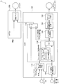
- FIG. 1 is a functional block diagram showing an embodiment of a driving force control device for a vehicle according to the present invention.
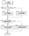
- FIG. 2 is a diagram for explaining a control routine of the failsafe control determination unit 110.
- FIG. 3 is a diagram for explaining a control routine of the engine control accelerator operation amount output unit 130.
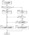
- FIG. 4 is a diagram for explaining a control routine of the transmission control accelerator operation amount output unit 170.
- FIG. 5 is a diagram showing an example of a shift map.
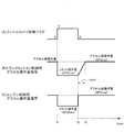
- FIG. 6 is a time chart showing changes in the amount of accelerator operation for transmission control input to the transmission when the embodiment is executed and changes in the amount of accelerator operation for engine control input to the engine.
- FIG. 1 is a functional block diagram showing an embodiment of a driving force control device for a vehicle according to the present invention.
- the driving force control device for a vehicle in some abnormal situation, for example, the driver newly installs a floor mat, and the accelerator pedal is released from the accelerator pedal by being hooked on the newly installed floor mat. Is a driving force control device that enables the vehicle to be safely stopped when the brake pedal is depressed even if it does not return.
- the driving force control device 1 of the vehicle includes an engine control module (hereinafter referred to as "ECM”) 100 and an automatic transmission control unit (hereinafter referred to as "ATCU”) 200.
- ECM engine control module
- ATCU automatic transmission control unit
- the driving force control device 1 of the vehicle repeatedly executes the following control every minute time (for example, several milliseconds).
- the ECM 100 and the ATCU 200 are separately illustrated, but a single controller may be used.
- the ECM 100 includes a failsafe control determination unit 110, an A / D conversion unit 120, an accelerator operation amount output unit 130 for engine control, various torque conversion correction units 140, a throttle target opening degree conversion unit 150, and throttle motor control.
- a unit 160 and an accelerator operation amount output unit 170 for transmission control are included.
- the failsafe control determination unit 110 determines whether failsafe control is necessary based on the neutral switch signal, the vehicle speed signal, the brake switch signal, and the actual accelerator operation amount. Details will be described later.
- the neutral switch signal is a signal that is turned on when the shift lever is in the N range or the P range and when the shift lever is in the other range.
- the brake switch signal is a signal which is turned on if the brake is depressed and turned off if the brake is not depressed.
- the accelerator operation amount sensor detects an actual operation amount of the accelerator pedal and outputs it as a voltage.
- the A / D conversion unit 120 converts an accelerator operation amount sensor signal output as a voltage into an accelerator actual operation amount.
- the engine control accelerator operation amount output unit 130 outputs an accelerator operation amount for controlling the engine. Details will be described later.
- the transmission control accelerator operation amount output unit 170 outputs an accelerator operation amount for controlling the automatic transmission. Details will be described later.
- the torque conversion correction unit 140 calculates the required engine torque based on the amount of operation of the engine control accelerator. Then, the target torque is calculated by correcting the engine torque with a required torque from the vehicle side such as vehicle dynamic control, traction control, and cruise control.
- the throttle target opening conversion unit 150 calculates a target opening of the intake throttle based on the calculated target torque.
- the throttle motor control unit 160 controls the throttle motor so as to achieve the calculated target opening.
- the ATCU 200 controls an automatic transmission. Details will be described later.
- FIG. 2 is a diagram for explaining a control routine of the failsafe control determination unit 110. As shown in FIG.
- step S111 the ECM 100 determines whether or not failsafe control is in progress. Specifically, if the failsafe control flag is "1", it is determined that failsafe control is being performed. If the failsafe control flag is "0", it is determined that failsafe control is not being performed. If not in control, the ECM 100 shifts the process to step S112. If in control, the ECM 100 shifts the process to step S117.
- step S112 the ECM 100 determines whether the neutral switch is on. If it is off, the ECM 100 shifts the process to step S113. If it is on, the ECM 100 temporarily exits the process.
- step S113 the ECM 100 determines whether the accelerator operation amount is larger than the reference value. If it is larger, the ECM 100 shifts the processing to step S114. If it is not large, the ECM 100 temporarily exits the process.
- step S114 the ECM 100 determines whether the brake switch is on. If it is off, the ECM 100 temporarily exits the process. If it is on, the ECM 100 shifts the process to step S115.
- step S115 the ECM 100 determines whether the vehicle speed is larger than a reference value. If it is not large, the ECM 100 temporarily exits the process. If so, the ECM 100 shifts the process to step S116.
- step S116 the ECM 100 sets the failsafe control flag to "1".
- step S117 the ECM 100 determines whether the brake switch is off. If it is on, the ECM 100 temporarily exits the process. If it is off, the ECM 100 shifts the process to step S118.
- step S118 the ECM 100 sets the failsafe control flag to "0".
- FIG. 3 is a diagram for explaining a control routine of the engine control accelerator operation amount output unit 130. As shown in FIG.
- step S131 the ECM 100 determines whether the failsafe control flag is "1". If “0”, the ECM 100 shifts the process to step S132. If “1”, the ECM 100 shifts the process to step S133.
- step S132 the ECM 100 sets a full open value as the accelerator operation amount limit value. Therefore, the accelerator operation amount is not substantially limited.
- step S133 the ECM 100 sets a predetermined limit value (APOlimit) as the accelerator operation amount limit value.
- APOlimit a predetermined limit value
- the predetermined limit value is determined in advance according to the specification of the vehicle.
- step S134 the ECM 100 determines whether the actual accelerator operation amount exceeds the accelerator operation amount limit value. If not exceeded, the ECM 100 shifts the process to step S135. If exceeded, the ECM 100 shifts the process to step S136.
- step S135 the ECM 100 outputs an accelerator actual operation amount (APOreal) as the engine control accelerator operation amount.
- APOreal accelerator actual operation amount
- step S136 the ECM 100 outputs an accelerator operation amount limit value as the engine control accelerator operation amount.
- FIG. 4 is a diagram for explaining a control routine of the transmission control accelerator operation amount output unit 170. As shown in FIG. 4
- step S171 the ECM 100 determines whether the failsafe control flag is "1". If “1”, the ECM 100 shifts the process to step S172. If it is "0”, the ECM 100 shifts the process to step S173.
- step S172 the ECM 100 resets the failsafe cancellation counter.
- step S173 the ECM 100 increments the failsafe cancellation counter.
- step S174 the ECM 100 determines whether or not the transition is completed based on the fail-safe cancellation counter and a predetermined time has elapsed. As described above, since this process is executed at fixed time intervals, the incremented failsafe cancellation counter indicates the elapsed time (ttrans) since the failsafe control is canceled. Based on this elapsed time, it is determined whether the transition is completed. A reference time (tend) for determining whether or not the transition is completed is set in advance according to the specification of the vehicle. The ECM 100 transfers the process to step S175 until the transition is completed. When the migration is completed, the ECM 100 transfers the process to step S176.
- step S175 the ECM 100 determines whether the actual accelerator operation amount output from the A / D conversion unit 120 exceeds a predetermined limit value.
- the predetermined limit value is the same as the limit value in step S133. If the predetermined limit value is not exceeded, the ECM 100 shifts the process to step S176. If the predetermined limit value is exceeded, the ECM 100 shifts the process to step S177.
- step S176 the ECM 100 outputs the engine control accelerator operation amount output from the engine control accelerator operation amount output unit 130 as the transmission control accelerator operation amount.
- step S177 the ECM 100 outputs the accelerator operation amount during transition as the transmission control accelerator operation amount.
- the accelerator operation amount is set based on the following equation (1).
- the ATCU 200 performs shift control by applying the vehicle speed and the accelerator operation amount for transmission control to the shift map.
- FIG. 5 is a diagram showing an example of a shift map.
- the horizontal axis is the vehicle speed, and the vertical axis is the accelerator operation amount.
- the thick line in the figure is the shift line used for upshifting.
- the thin line in the figure is a shift line used for downshifting.
- the control of this embodiment is as follows.
- the failsafe control determination unit 110 performs steps S111 ⁇ S112 ⁇ S113 ⁇ S114 ⁇ S115 if the brake pedal is depressed. Process S116 and set the fail safe control flag to "1".
- the engine control accelerator operation amount output unit 130 processes steps S131 ⁇ S133 ⁇ S134 ⁇ S136 and outputs an accelerator operation amount restriction value smaller than the actual accelerator operation amount as the engine control accelerator operation amount.
- the torque conversion correction unit 140 calculates the target torque
- the throttle target opening degree conversion unit 150 calculates the target opening degree of the intake throttle
- the throttle motor control unit 160 controls the throttle motor.
- the throttle opening degree is reduced and the engine output is reduced.
- the negative pressure of the master back increases and the brake becomes more effective.
- the transmission control accelerator operation amount output unit 170 performs the shift control based on the accelerator operation amount for engine control, that is, the accelerator operation amount limited by the limit value, by processing step S171 ⁇ S172 ⁇ S176.
- the timing at this time is time t1 in FIG. Since the limited accelerator operation amount is employed as the transmission control accelerator operation amount, the transmission is upshifted. That is, for example, when traveling at the third speed at point D in FIG. 5, if the limited accelerator operation amount is adopted as the transmission control accelerator operation amount, the accelerator operation amount is at point A as indicated by the downward arrow. Up to 6 speeds are limited.
- the fail-safe control determination unit 110 sets “0” to the fail-safe control flag by processing steps S111 ⁇ S117 ⁇ S118.
- the engine control accelerator operation amount output unit 130 processes step S131 ⁇ S132 ⁇ S134 ⁇ S135 to release the restriction of the accelerator operation amount, and outputs the actual accelerator operation amount as the engine control accelerator operation amount.
- the torque conversion correction unit 140 calculates the target torque
- the throttle target opening degree conversion unit 150 calculates the target opening degree of the intake throttle
- the throttle motor control unit 160 controls the throttle motor. As a result, the throttle opening increases and the engine output increases.
- the transmission control accelerator operation amount output unit 170 performs the process of steps S171 ⁇ S173 ⁇ S174 ⁇ S175 ⁇ S177, and performs shift control based on the accelerator operation amount during transition.
- the timing at this time is time t2 in FIG.
- the transmission control accelerator operation amount output unit 170 performs the process from step S174 to step S176, and performs shift control based on the engine control accelerator operation amount. Since the limitation of the accelerator operation amount is released at time t2, the engine control accelerator operation amount is the actual accelerator operation amount. That is, when the shift control of the accelerator operation amount is canceled at the sixth speed of point A in FIG. 5 due to the restriction of the accelerator operation amount, if the restriction of the accelerator operation amount is released, as shown by the upward arrow, Shift down and shift down to 4th gear at point C and return to point D.
- the restriction when canceling the fail-safe control, the restriction is canceled by taking a predetermined time from the restricted engine control accelerator operation amount. That is, when the fail safe control is released, the shift control based on the limited accelerator operation amount is shifted to the shift control based on the actual accelerator operation amount taking a predetermined time. Then, since it is gradually shifted (shifted down), sudden acceleration can be avoided.
- the shift control is performed based on the accelerator operation amount for engine control whose restriction has been released after the engine control unit releases the restriction on the intake throttle opening degree. It was made to do.
- the engine control unit releases the restriction on the intake throttle opening degree, and performs shift control using the engine control accelerator operation amount that is delayed after that. Then, the restriction is canceled by taking a predetermined time from the restricted amount of acceleration for engine control. Then, since it is gradually shifted (shifted down), sudden acceleration can be avoided.
- the opening degree of the intake throttle is reduced in order to limit the engine output in the above embodiment, the present invention is not limited to this.
- the fuel injection amount may be reduced.
- the shift control is performed after the engine output is limited and a predetermined time has elapsed.
- the present invention is not limited to this, and the shift control is performed after traveling the predetermined distance by limiting the engine output. May be
- the failsafe control is determined based on the neutral switch, the accelerator operation amount, the brake switch, and the vehicle speed, but may be determined only by the brake switch.
Landscapes
- Engineering & Computer Science (AREA)
- Mechanical Engineering (AREA)
- General Engineering & Computer Science (AREA)
- Automation & Control Theory (AREA)
- Transportation (AREA)
- Control Of Driving Devices And Active Controlling Of Vehicle (AREA)
- Control Of Transmission Device (AREA)
- Auxiliary Drives, Propulsion Controls, And Safety Devices (AREA)
Abstract
車両の駆動力制御装置は、ブレーキペダルの踏み込みに基づいて、フェールセーフ制御が必要であるか否かを判定するフェールセーフ判定部と、フェールセーフ制御が必要と判定されたときには制限されたアクセル操作量に基づいて変速制御してフェールセーフ制御し、フェールセーフ制御が不要と判定されたときにはアクセル実操作量に基づいて変速制御するとともに、フェールセーフ制御を解除するときには、制限されたアクセル操作量に基づく変速制御から所定時間をかけてアクセル実操作量に基づく変速制御に移行するトランスミッション制御部と、を備える。
Description
この発明は、車両の駆動力を制御する装置及び方法に関する。
アクセルペダルの操作量を電気信号に変換して、この信号に基づいてアクチュエーターを駆動してスロットルバルブの開度を調整する、いわゆるドライブ・バイ・ワイヤ(drive-by-wire)システムが広く採用されている。
そして、JPH04-50551Aでは、スロットルバルブが固着した場合に備えて、アクセルペダルがたとえ踏まれていると検知したときでも、ブレーキペダルが踏まれたら、即時にトランスミッションを最小変速比に制御する。
しかしながら、前述した従来の方法では、ブレーキペダルが踏まれてトランスミッションが最小変速比に制御された後に、ブレーキペダルが踏まれなくなると、元の変速比に戻される。すると、シフトダウンが発生して唐突な加速となってしまい、ドライバーは違和感を感じてしまう。
本発明は、このような従来の問題点に着目してなされたものであり、一旦変速比を小さくした場合であっても、ドライバーに違和感を感じさせることなく元の変速比に戻すために変速制御することができる車両の駆動力制御装置及び駆動力制御方法を提供することを目的とする。
本発明のある態様によれば、ブレーキペダルの踏み込みに基づいて、フェールセーフ制御が必要であるか否かを判定するフェールセーフ判定部と、フェールセーフ制御が必要と判定されたときには制限されたアクセル操作量に基づいて変速制御してフェールセーフ制御し、フェールセーフ制御が不要と判定されたときにはアクセル実操作量に基づいて変速制御するとともに、フェールセーフ制御を解除するときには、制限されたアクセル操作量に基づく変速制御から所定時間をかけてアクセル実操作量に基づく変速制御に移行するトランスミッション制御部と、を備える車両の駆動力を制御する装置が提供される。
本発明の実施形態及び利点については、添付された図面とともに以下に詳細に説明される。
図1は、本発明による車両の駆動力制御装置の一実施形態を示す機能ブロック図である。
本発明による車両の駆動力制御装置は、何らかの異状事態、たとえば、ドライバーがフロアマットを新たに設置し、アクセルペダルがこの新たに設置したフロアマットに引っかかることによってアクセルペダルから足を離してアクセルペダルが戻らなくなっても、ブレーキペダルが踏まれると、車両を安全に停止可能にする駆動力制御装置である。
車両の駆動力制御装置1は、エンジンコントロールモジュール(Engine Control Module;以下「ECM」と称す)100と、オートマチックトランスミッションコントロールユニット(Automatic Transmission Control Unit;以下「ATCU」と称す)200と、を含む。車両の駆動力制御装置1は、スタートスイッチがオンされると、微小時間(たとえば数ミリ秒)ごとに以下の制御を繰り返し実行する。
なお本実施形態では、ECM100とATCU200とを分けて図示しているが、単一のコントローラーであってもよい。
以下では実施形態の理解を容易にするために、各コントローラーの機能を仮想的なユニットとして説明する。
ECM100は、フェールセーフ制御判定ユニット110と、A/D変換ユニット120と、エンジン制御用アクセル操作量出力ユニット130と、トルク変換各種補正ユニット140と、スロットル目標開度変換ユニット150と、スロットルモーター制御ユニット160と、トランスミッション制御用アクセル操作量出力ユニット170と、を含む。
フェールセーフ制御判定ユニット110は、ニュートラルスイッチ信号、車速信号、ブレーキスイッチ信号、アクセル実操作量に基づいてフェールセーフ制御が必要であるか否かを判定する。詳細は、後述する。なおニュートラルスイッチ信号は、シフトレバーがNレンジ又はPレンジのときにオン/それ以外のレンジのときにオフとなる信号である。ブレーキスイッチ信号は、ブレーキが踏まれていればオン/踏まれていなければオフとなる信号である。アクセル操作量センサーは、アクセルペダルの実操作量を検出して電圧として出力する。
A/D変換ユニット120は、電圧として出力されたアクセル操作量センサー信号をアクセル実操作量に換算する。
エンジン制御用アクセル操作量出力ユニット130は、エンジンを制御するためのアクセル操作量を出力する。詳細は、後述する。トランスミッション制御用アクセル操作量出力ユニット170は、オートマチックトランスミッションを制御するためのアクセル操作量を出力する。詳細は、後述する。
トルク変換各種補正ユニット140は、エンジン制御用アクセル操作量に基づいて必要なエンジントルクを演算する。そして、そのエンジントルクを、ビークルダイナミックコントロール(Vehicle Dynamic Control)、トラクションコントロール(Traction Control)、クルーズコントロール(Cruise Control)のような、車両側からの要求トルクで補正して、目標トルクを算出する。
スロットル目標開度変換ユニット150は、算出された目標トルクに基づいて、吸気スロットルの目標開度を算出する。
スロットルモーター制御ユニット160は、算出された目標開度になるように、スロットルモーターを制御する。
ATCU200は、オートマチックトランスミッションをコントロールする。詳細は、後述する。
図2は、フェールセーフ制御判定ユニット110の制御ルーチンを説明する図である。
ステップS111においてECM100は、フェールセーフ制御中であるか否かを判定する。具体的にはフェールセーフ制御フラグが「1」であればフェールセーフ制御中であると判定する。フェールセーフ制御フラグが「0」であればフェールセーフ制御中ではないと判定する。制御中でなければECM100はステップS112に処理を移行する。制御中であればECM100はステップS117に処理を移行する。
ステップS112においてECM100は、ニュートラルスイッチがオンであるか否かを判定する。オフであればECM100はステップS113に処理を移行する。オンであればECM100は一旦処理を抜ける。
ステップS113においてECM100は、アクセル操作量が基準値よりも大きいか否かを判定する。大きければECM100はステップS114に処理を移行する。大きくなければECM100は一旦処理を抜ける。
ステップS114においてECM100は、ブレーキスイッチがオンであるか否かを判定する。オフであればECM100は一旦処理を抜ける。オンであればECM100はステップS115に処理を移行する。
ステップS115においてECM100は、車速が基準値よりも大きいか否かを判定する。大きくなければECM100は一旦処理を抜ける。大きければECM100はステップS116に処理を移行する。
ステップS116においてECM100は、フェールセーフ制御フラグに「1」をセットする。
ステップS117においてECM100は、ブレーキスイッチがオフであるか否かを判定する。オンであればECM100は一旦処理を抜ける。オフであればECM100はステップS118に処理を移行する。
ステップS118においてECM100は、フェールセーフ制御フラグに「0」をセットする。
図3は、エンジン制御用アクセル操作量出力ユニット130の制御ルーチンを説明する図である。
ステップS131においてECM100は、フェールセーフ制御フラグが「1」であるか否かを判定する。「0」であればECM100はステップS132に処理を移行する。「1」であればECM100はステップS133に処理を移行する。
ステップS132においてECM100は、アクセル操作量制限値としてフルオープン値を設定する。したがって実質的にはアクセル操作量を制限しない。
ステップS133においてECM100は、アクセル操作量制限値として所定リミット値(APOlimit)を設定する。この所定リミット値は、車両の仕様に応じて予め決められている。
ステップS134においてECM100は、アクセル実操作量がアクセル操作量制限値を超えるか否かを判定する。超えなければECM100はステップS135に処理を移行する。超えればECM100はステップS136に処理を移行する。
ステップS135においてECM100は、エンジン制御用アクセル操作量としてアクセル実操作量(APOreal)を出力する。
ステップS136においてECM100は、エンジン制御用アクセル操作量としてアクセル操作量制限値を出力する。
図4は、トランスミッション制御用アクセル操作量出力ユニット170の制御ルーチンを説明する図である。
ステップS171においてECM100は、フェールセーフ制御フラグが「1」であるか否かを判定する。「1」であればECM100はステップS172に処理を移行する。「0」であればECM100はステップS173に処理を移行する。
ステップS172においてECM100は、フェールセーフ解除カウンターをリセットする。
ステップS173においてECM100は、フェールセーフ解除カウンターをインクリメントする。
ステップS174においてECM100は、フェールセーフ解除カウンターに基づいて所定時間が経過して移行が完了したか否かを判定する。上述のように、この処理は一定時間ごとに実行されるので、インクリメントされたフェールセーフ解除カウンターによってフェールセーフ制御が解除されてからの経過時間(ttrans)が判る。この経過時間に基づいて移行が完了したか否かを判定する。なお移行が完了したか否かを判定するための基準時間(tend)は予め車両の仕様に応じて設定されている。移行が完了するまではECM100はステップS175に処理を移行する。移行が完了したらECM100は、ステップS176に処理を移行する。
ステップS175においてECM100は、A/D変換ユニット120から出力されるアクセル実操作量が所定リミット値を超えるか否かを判定する。なおこの所定リミット値はステップS133のリミット値と同じである。所定リミット値を超えなければECM100はステップS176に処理を移行する。所定リミット値を超えればECM100は、ステップS177に処理を移行する。
ステップS176においてECM100は、エンジン制御用アクセル操作量出力ユニット130から出力されるエンジン制御用アクセル操作量を
トランスミッション制御用アクセル操作量として出力する。
トランスミッション制御用アクセル操作量として出力する。
ステップS177においてECM100は、移行中アクセル操作量をトランスミッション制御用アクセル操作量として出力する。なお移行中アクセル操作量は次式(1)に基づいて設定される。

そしてATCU200は、車速とトランスミッション制御用アクセル操作量とを変速マップに適用して変速制御する。
図5は、変速マップの一例を示す図である。
横軸が車速であり、縦軸がアクセル操作量である。図中太線がシフトアップで使用される変速ラインである。図中細線がシフトダウンで使用される変速ラインである。
本実施形態の制御を実行すると以下のようになる。
すなわち走行中に、何らかの異状事態によってアクセルペダルから足を離してもアクセルペダルが戻らなくなっても、ブレーキペダルが踏まれると、フェールセーフ制御判定ユニット110は、ステップS111→S112→S113→S114→S115→S116と処理して、フェールセーフ制御フラグに「1」をセットする。
そして、エンジン制御用アクセル操作量出力ユニット130は、ステップS131→S133→S134→S136と処理して、エンジン制御用アクセル操作量として、アクセル実操作量よりも小さいアクセル操作量制限値を出力する。そして、トルク変換各種補正ユニット140が目標トルクを算出し、スロットル目標開度変換ユニット150が吸気スロットルの目標開度を算出し、スロットルモーター制御ユニット160がスロットルモーターを制御する。これによってスロットル開度が絞られてエンジン出力が低下する。またスロットル開度が絞られると吸気負圧が上昇するので、マスターバックの負圧が大きくなりブレーキが効きやすくなる。
一方、トランスミッション制御用アクセル操作量出力ユニット170は、ステップS171→S172→S176と処理して、エンジン制御用アクセル操作量、すなわちリミット値で制限されたアクセル操作量に基づいて、変速制御する。なおこのときのタイミングが図6の時刻t1である。トランスミッション制御用アクセル操作量として制限されたアクセル操作量が採用されるので、トランスミッションはシフトアップする。すなわち、たとえば図5のD点の3速で走行しているときに、トランスミッション制御用アクセル操作量として制限されたアクセル操作量が採用されると、下向き矢印のように、アクセル操作量がA点まで制限されて6速までシフトアップする。
フェールセーフ制御中にブレーキペダルが踏まれなくなると、フェールセーフ制御判定ユニット110は、ステップS111→S117→S118と処理して、フェールセーフ制御フラグに「0」をセットする。
そして、エンジン制御用アクセル操作量出力ユニット130は、ステップS131→S132→S134→S135と処理して、アクセル操作量の制限を解除し、エンジン制御用アクセル操作量としてアクセル実操作量を出力する。そして、トルク変換各種補正ユニット140が目標トルクを算出し、スロットル目標開度変換ユニット150が吸気スロットルの目標開度を算出し、スロットルモーター制御ユニット160がスロットルモーターを制御する。これによってスロットル開度が大きくなってエンジン出力が上昇する。
一方、トランスミッション制御用アクセル操作量出力ユニット170は、ステップS171→S173→S174→S175→S177と処理して、移行中アクセル操作量に基づいて変速制御する。なおこのときのタイミングが図6の時刻t2である。
図6の時刻t3になって移行が完了すると、トランスミッション制御用アクセル操作量出力ユニット170は、ステップS174→S176と処理して、エンジン制御用アクセル操作量に基づいて変速制御する。なお時刻t2でアクセル操作量の制限を解除されているので、エンジン制御用アクセル操作量はアクセル実操作量である。すなわち、アクセル操作量の制限によって図5のA点の6速で変速制御しているときに、アクセル操作量の制限が解除されると、上向き矢印のように、途中でB点で5速にシフトダウンされ、さらにC点で4速にシフトダウンされてD点に戻る。
本実施形態では、フェールセーフ制御を解除するときに、制限されたエンジン制御用アクセル操作量から所定時間をかけて制限を解除する。すなわち、フェールセーフ制御を解除するときには、制限されたアクセル操作量に基づく変速制御から所定時間をかけてアクセル実操作量に基づく変速制御に移行する。すると徐々に変速(シフトダウン)されるので、唐突な加速を回避できるのである。
また、本実施形態では、フェールセーフ制御を解除するときに、エンジン制御部が吸気スロットル開度を制限を解除するのに遅れて、制限が解除されたエンジン制御用アクセル操作量に基づいて変速制御するようにした。
仮にエンジン制御部が吸気スロットル開度を制限を解除するのと同じタイミングで、制限が解除されたエンジン制御用アクセル操作量に基づいて変速制御すると、エンジントルクが回復するのと同時にシフトダウンが発生して、唐突な加速となってしまい、ドライバーは違和感を感じてしまう。
これに対して本実施形態は、ますエンジン制御部が吸気スロットル開度を制限を解除して、それに遅れて制限されたエンジン制御用アクセル操作量を用いて変速制御する。そして、制限されたエンジン制御用アクセル操作量から所定時間をかけて制限を解除する。すると徐々に変速(シフトダウン)されるので、唐突な加速を回避できるのである。
以上、本発明の実施形態について説明したが、上記実施形態は本発明の適用例の一部を示したに過ぎず、本発明の技術的範囲を上記実施形態の具体的構成に限定する趣旨ではない。
上記実施形態ではエンジン出力を制限するために吸気スロットルの開度を小さくしたが、これに限られるものではなく、たとえば燃料噴射量を減量させてもよい。
また、上記実施形態では、エンジン出力を制限して所定時間が経過してから変速制御したが、これに限られるものではなく、エンジン出力を制限して所定の距離を走行してから変速制御してもよい。
また上記実施形態ではフェールセーフ制御は、ニュートラルスイッチと、アクセル操作量と、ブレーキスイッチと、車速とに基づいて判定したが、ブレーキスイッチだけで判定してもよい。
本願は2010年4月13日に日本国特許庁に出願された特願2010-92173に基づく優先権を主張し、この出願の全ての内容は参照により本明細書に組み込まれる。
Claims (4)
- ブレーキペダルの踏み込みに基づいて、フェールセーフ制御が必要であるか否かを判定するフェールセーフ判定部(110)と、
フェールセーフ制御が必要と判定されたときには制限されたアクセル操作量に基づいて変速制御してフェールセーフ制御し、フェールセーフ制御が不要と判定されたときにはアクセル実操作量に基づいて変速制御するとともに、前記フェールセーフ制御を解除するときには、前記制限されたアクセル操作量に基づく変速制御から所定時間をかけて前記アクセル実操作量に基づく変速制御に移行するトランスミッション制御部(170,200)と、
を備える車両の駆動力制御装置。 - 請求項1に記載の車両の駆動力制御装置において、
フェールセーフ制御が必要と判定されたときには制限されたアクセル操作量に基づいてエンジン出力を制限してフェールセーフ制御するとともに、フェールセーフ制御が不要と判定されたときにはアクセル実操作量に基づいてエンジン出力を制御するエンジン制御部(130,140,150,160)をさらに備え、
前記トランスミッション制御部(170,200)は、前記フェールセーフ制御を解除するときには、前記エンジン制御部(130,140,150,160)がアクセル実操作量に基づいてエンジン出力を制御するのに遅れて、前記アクセル実操作量に基づいて変速制御する、
ことを特徴とする車両の駆動力制御装置。 - 請求項1又は請求項2に記載の車両の駆動力制御装置において、
前記トランスミッション制御部(170,200)は、フェールセーフ制御が必要であるときにはシフトアップするとともに、フェールセーフ制御が不要になったときにはシフトダウンする、
ことを特徴とする車両の駆動力制御装置。 - ブレーキペダルの踏み込みに基づいて、フェールセーフ制御が必要であるか否かを判定するフェールセーフ判定工程(S110)と、
フェールセーフ制御が必要であるときにはシフトアップするとともに、フェールセーフ制御が不要になったときには所定時間をかけてシフトダウンするトランスミッション制御工程(S170)と、
を備える車両の駆動力制御方法。
Applications Claiming Priority (2)
| Application Number | Priority Date | Filing Date | Title |
|---|---|---|---|
| JP2010092173A JP2011219022A (ja) | 2010-04-13 | 2010-04-13 | 車両の駆動力制御装置及び駆動力制御方法 |
| JP2010-092173 | 2010-04-13 |
Publications (1)
| Publication Number | Publication Date |
|---|---|
| WO2011129239A1 true WO2011129239A1 (ja) | 2011-10-20 |
Family
ID=44798615
Family Applications (1)
| Application Number | Title | Priority Date | Filing Date |
|---|---|---|---|
| PCT/JP2011/058699 Ceased WO2011129239A1 (ja) | 2010-04-13 | 2011-04-06 | 車両の駆動力制御装置及び駆動力制御方法 |
Country Status (2)
| Country | Link |
|---|---|
| JP (1) | JP2011219022A (ja) |
| WO (1) | WO2011129239A1 (ja) |
Citations (2)
| Publication number | Priority date | Publication date | Assignee | Title |
|---|---|---|---|---|
| JPH0450551A (ja) * | 1990-06-19 | 1992-02-19 | Mitsubishi Motors Corp | 無段変速機の変速比制御装置 |
| JP2010048323A (ja) * | 2008-08-21 | 2010-03-04 | Nissan Motor Co Ltd | 車速制限解除時における自動変速機の変速制御装置 |
-
2010
- 2010-04-13 JP JP2010092173A patent/JP2011219022A/ja active Pending
-
2011
- 2011-04-06 WO PCT/JP2011/058699 patent/WO2011129239A1/ja not_active Ceased
Patent Citations (2)
| Publication number | Priority date | Publication date | Assignee | Title |
|---|---|---|---|---|
| JPH0450551A (ja) * | 1990-06-19 | 1992-02-19 | Mitsubishi Motors Corp | 無段変速機の変速比制御装置 |
| JP2010048323A (ja) * | 2008-08-21 | 2010-03-04 | Nissan Motor Co Ltd | 車速制限解除時における自動変速機の変速制御装置 |
Also Published As
| Publication number | Publication date |
|---|---|
| JP2011219022A (ja) | 2011-11-04 |
Similar Documents
| Publication | Publication Date | Title |
|---|---|---|
| EP2017152B1 (en) | Vehicle engine control apparatus | |
| CN103597189B (zh) | 车辆的控制装置 | |
| US20080306668A1 (en) | CRUISE CONTROL INTERACTION WITH DRIVER ComMANDED SPEED RESET | |
| JP5261306B2 (ja) | 内燃機関の制御装置 | |
| US9434373B2 (en) | Automatic transmission control device | |
| US8485942B2 (en) | Vehicle control system and vehicle control method | |
| JP6274148B2 (ja) | 車両の制御装置 | |
| CN106143489A (zh) | 定速巡航控制方法及系统 | |
| JP4941357B2 (ja) | エンジン制御装置 | |
| JP2002192979A (ja) | 車両の走行制御装置 | |
| JP2006233870A (ja) | エンジン出力制御装置、エンジン出力制御方法およびエンジン出力制御プログラム | |
| WO2014045901A1 (ja) | 車両の制御装置 | |
| JP2011163535A (ja) | 機械式自動変速機の制御装置 | |
| JP6011352B2 (ja) | 車両の惰性走行制御装置 | |
| EP2754925B1 (en) | Control device for continuously variable transmission | |
| WO2018168459A1 (ja) | 車両の変速機制御装置 | |
| CN107923523A (zh) | 自动变速器的控制装置 | |
| JP2011219021A (ja) | 車両の駆動力制御装置及び駆動力制御方法 | |
| CN103518083A (zh) | 车辆的控制装置 | |
| US11318840B2 (en) | Vehicle travel control method and vehicle travel control device | |
| JP2006142963A (ja) | 車両の駆動力制御装置 | |
| JP2011219022A (ja) | 車両の駆動力制御装置及び駆動力制御方法 | |
| JP3147741B2 (ja) | 無段変速機の変速制御装置 | |
| JP5355164B2 (ja) | 自動変速機の制御装置 | |
| JP4120617B2 (ja) | 車両の減速制御装置 |
Legal Events
| Date | Code | Title | Description |
|---|---|---|---|
| 121 | Ep: the epo has been informed by wipo that ep was designated in this application |
Ref document number: 11768760 Country of ref document: EP Kind code of ref document: A1 |
|
| NENP | Non-entry into the national phase |
Ref country code: DE |
|
| 122 | Ep: pct application non-entry in european phase |
Ref document number: 11768760 Country of ref document: EP Kind code of ref document: A1 |