WO2011129188A1 - 太陽光発電システム、電力変換装置および集電箱 - Google Patents
太陽光発電システム、電力変換装置および集電箱 Download PDFInfo
- Publication number
- WO2011129188A1 WO2011129188A1 PCT/JP2011/057312 JP2011057312W WO2011129188A1 WO 2011129188 A1 WO2011129188 A1 WO 2011129188A1 JP 2011057312 W JP2011057312 W JP 2011057312W WO 2011129188 A1 WO2011129188 A1 WO 2011129188A1
- Authority
- WO
- WIPO (PCT)
- Prior art keywords
- power
- power conversion
- connection terminal
- conversion device
- terminal
- Prior art date
- Legal status (The legal status is an assumption and is not a legal conclusion. Google has not performed a legal analysis and makes no representation as to the accuracy of the status listed.)
- Ceased
Links
Images


Classifications
-
- H—ELECTRICITY
- H10—SEMICONDUCTOR DEVICES; ELECTRIC SOLID-STATE DEVICES NOT OTHERWISE PROVIDED FOR
- H10F—INORGANIC SEMICONDUCTOR DEVICES SENSITIVE TO INFRARED RADIATION, LIGHT, ELECTROMAGNETIC RADIATION OF SHORTER WAVELENGTH OR CORPUSCULAR RADIATION
- H10F77/00—Constructional details of devices covered by this subclass
- H10F77/95—Circuit arrangements
- H10F77/953—Circuit arrangements for devices having potential barriers
- H10F77/955—Circuit arrangements for devices having potential barriers for photovoltaic devices
-
- H—ELECTRICITY
- H02—GENERATION; CONVERSION OR DISTRIBUTION OF ELECTRIC POWER
- H02J—CIRCUIT ARRANGEMENTS OR SYSTEMS FOR SUPPLYING OR DISTRIBUTING ELECTRIC POWER; SYSTEMS FOR STORING ELECTRIC ENERGY
- H02J3/00—Circuit arrangements for AC mains or AC distribution networks
- H02J3/38—Arrangements for parallely feeding a single network by two or more generators, converters or transformers
- H02J3/381—Dispersed generators
-
- H—ELECTRICITY
- H02—GENERATION; CONVERSION OR DISTRIBUTION OF ELECTRIC POWER
- H02J—CIRCUIT ARRANGEMENTS OR SYSTEMS FOR SUPPLYING OR DISTRIBUTING ELECTRIC POWER; SYSTEMS FOR STORING ELECTRIC ENERGY
- H02J2300/00—Systems for supplying or distributing electric power characterised by decentralized, dispersed, or local generation
- H02J2300/20—The dispersed energy generation being of renewable origin
- H02J2300/22—The renewable source being solar energy
- H02J2300/24—The renewable source being solar energy of photovoltaic origin
-
- Y—GENERAL TAGGING OF NEW TECHNOLOGICAL DEVELOPMENTS; GENERAL TAGGING OF CROSS-SECTIONAL TECHNOLOGIES SPANNING OVER SEVERAL SECTIONS OF THE IPC; TECHNICAL SUBJECTS COVERED BY FORMER USPC CROSS-REFERENCE ART COLLECTIONS [XRACs] AND DIGESTS
- Y02—TECHNOLOGIES OR APPLICATIONS FOR MITIGATION OR ADAPTATION AGAINST CLIMATE CHANGE
- Y02B—CLIMATE CHANGE MITIGATION TECHNOLOGIES RELATED TO BUILDINGS, e.g. HOUSING, HOUSE APPLIANCES OR RELATED END-USER APPLICATIONS
- Y02B10/00—Integration of renewable energy sources in buildings
- Y02B10/10—Photovoltaic [PV]
-
- Y—GENERAL TAGGING OF NEW TECHNOLOGICAL DEVELOPMENTS; GENERAL TAGGING OF CROSS-SECTIONAL TECHNOLOGIES SPANNING OVER SEVERAL SECTIONS OF THE IPC; TECHNICAL SUBJECTS COVERED BY FORMER USPC CROSS-REFERENCE ART COLLECTIONS [XRACs] AND DIGESTS
- Y02—TECHNOLOGIES OR APPLICATIONS FOR MITIGATION OR ADAPTATION AGAINST CLIMATE CHANGE
- Y02E—REDUCTION OF GREENHOUSE GAS [GHG] EMISSIONS, RELATED TO ENERGY GENERATION, TRANSMISSION OR DISTRIBUTION
- Y02E10/00—Energy generation through renewable energy sources
- Y02E10/50—Photovoltaic [PV] energy
- Y02E10/56—Power conversion systems, e.g. maximum power point trackers
-
- Y—GENERAL TAGGING OF NEW TECHNOLOGICAL DEVELOPMENTS; GENERAL TAGGING OF CROSS-SECTIONAL TECHNOLOGIES SPANNING OVER SEVERAL SECTIONS OF THE IPC; TECHNICAL SUBJECTS COVERED BY FORMER USPC CROSS-REFERENCE ART COLLECTIONS [XRACs] AND DIGESTS
- Y02—TECHNOLOGIES OR APPLICATIONS FOR MITIGATION OR ADAPTATION AGAINST CLIMATE CHANGE
- Y02P—CLIMATE CHANGE MITIGATION TECHNOLOGIES IN THE PRODUCTION OR PROCESSING OF GOODS
- Y02P80/00—Climate change mitigation technologies for sector-wide applications
- Y02P80/20—Climate change mitigation technologies for sector-wide applications using renewable energy
Definitions
- the present invention relates to a solar power generation system, a power conversion device, and a current collection box.
- a power conversion device that converts the DC power into AC power is provided. .
- the above power conversion device has a rated output that varies depending on the application.
- a power conversion device having a rated output of about 3 kW is used in a general household solar power generation system.
- a power converter having a rated output of about 3 kW for example, the one described in Patent Document 1 is known.
- a power converter having a rated output of 100 kW or 250 kW is used for industrial use.
- power converters with rated outputs of 100 kW and 250 kW have come to the market.
- the lifetime of a solar cell module is generally said to be 20 years or longer, but the nominal life of a power converter as a peripheral device is about 10 years. For this reason, when it exceeds 10 years, the maintenance of a power converter device may be needed. That is, there is a high possibility that maintenance of the power conversion device will come after the solar power generation system is constructed and before the solar cell module is replaced.
- the power converter for home use has a rated output of about 3 kW and a weight of about 30 kg, so it can be moved by about two workers. For this reason, when maintenance becomes large, it becomes possible to exchange with a new power converter.
- power converters for industrial and solar power plants have a rated output of 100 kW or 250 kW and a weight of about 1 t or more. For this reason, it is very difficult to replace the device itself. Moreover, since such a power converter has a large rated output, the cable around the power converter becomes as thick as about 150 sq, and the work of connecting and disconnecting the cable is physically difficult. Further, since a direct current voltage is applied to the cable for a long time, it may be difficult to remove the cable due to aging.
- the present invention has been made to solve the above-described problems, and one object of the present invention is to provide a photovoltaic power generation system excellent in maintainability, a power conversion device used in the photovoltaic power generation system, and a collector. It is to provide an electric box.
- a photovoltaic power generation system includes a solar cell array including a plurality of solar cell modules, a current collection box for collecting power from the solar cell array, From the solar cell array, a power conversion device that is connected to the electrical box and includes a power conversion unit that converts DC power from the solar cell array into AC power, a first electrical wiring that connects the current collection box and the power conversion device, and The first connection terminal to which the direct current power is supplied and the first switch for cutting off the output from the solar cell array to the power converter are connected to the first power terminal.
- the first switch by opening the first switch, the output from the solar cell array to the power conversion unit Can be cut off.
- the first connection terminal by connecting the alternative power conversion device to the first connection terminal, the path of the DC power from the solar cell array can be switched to the alternative power conversion device. That is, the power conversion that should be performed by the power conversion device can be performed by the alternative power conversion device. Thereby, the maintenance operation
- maintenance work can be performed without removing the first electrical wiring connecting the current collection box and the power converter.
- a power converter having a large rated output is used in a photovoltaic power generation system for industrial use or photovoltaic power plant.
- a power converter having a large rated output has a weight of about 1 ton or more. Therefore, it is very difficult to replace the device itself.
- maintenance work can be performed without replacing the device itself and without removing the first electrical wiring that connects the current collection box and the power conversion device. Since it can be performed, maintainability can be improved.
- the solar power generation system according to the first aspect is used for industrial use or for a solar power plant, in particular, it is possible to improve maintainability, but even when used for general home use, Maintainability can be improved.
- the current collection box and the power conversion device each include a first terminal to which the first electric wiring is connected, and the first connection terminal.
- the first switch is preferably provided in at least one of the current collection box and the power converter.
- the power conversion device includes a first connection terminal, a first terminal, and a first switch. If comprised in this way, the maintainability of a solar power generation system can be improved easily.
- the first terminal in the power conversion device is connected to the first connection terminal, and the first connection terminal is the first connection terminal. It is preferable to be connected to the power conversion unit via a switch.
- the current collection box and the power conversion device can each be configured to include a first terminal to which the first electrical wiring is connected.
- the first terminal may be configured to also serve as the first connection terminal.
- the current collection box includes a first connection terminal
- the power conversion device includes a first switch that blocks output from the solar cell array to the power conversion unit. It may be configured.
- the current collection box includes a first terminal to which the first electric wiring is connected, a first connection terminal, and a first switch, and the first connection terminal is the first opening / closing. It can also be set as the structure connected with the 1st terminal through the container.
- the first connection terminal is provided between the current collection box and the power conversion device, and is connected to the power conversion unit via the first switch. Also good.
- the first switch can be configured by a changeover switch that switches a supply destination of DC power from the solar cell array to the power conversion unit or the first connection terminal. If comprised in this way, in the state to which the solar cell array and the power converter part were connected, since the direct-current power from a solar cell array is not supplied to the 1st connection terminal, it is to a 1st connection terminal. An alternative power converter can be safely connected. And by switching the switch unit, it is possible to shut off the output from the solar cell array to the power conversion unit and to supply DC power to the first connection terminal, so that the power conversion that the power conversion device should carry out It can be carried by an alternative power converter.
- the power conversion device is preferably configured to include a second terminal as an AC output terminal connected to the output side of the power conversion unit.
- the photovoltaic power generation system according to the first aspect further includes a second connection terminal connected to the second terminal. If comprised in this way, a maintenance operation
- work of a power converter device can be easily performed, without stopping the electric power generation in a solar power generation system by connecting an alternative power converter device also to this 2nd connection terminal.
- the power converter of a power converter device can be reliably electrically disconnected from a solar cell array by making a 2nd switch into an open state. Thereby, maintenance work can be performed more safely.
- the power conversion device may be configured to include the second connection terminal.
- the second terminal is connected to the power conversion unit via the second connection terminal.
- the power conversion device can be configured to include a second connection terminal and a second switch connected to the second terminal.
- the second terminal is connected to the second connection terminal, and the second connection terminal is connected to the power conversion unit via the second switch.
- the second connection terminal is connected via the second electrical wiring, It can also be set as the structure connected with the 2nd terminal.
- the second terminal may be configured to also serve as the second connection terminal.
- the second connection terminal is preferably a dedicated connector. If comprised in this way, safety
- the first connection terminal includes a dedicated connector. If comprised in this way, safety
- the alternative power conversion device may be mounted on the moving means. If comprised in this way, an alternative power converter device can be easily arrange
- the moving means for example, a vehicle such as a truck can be used.
- the alternative power conversion device preferably has a function of diagnosing the state of the power conversion device.
- a power conversion device is a power conversion device used in the solar power generation system according to the first aspect.
- a power converter is connected to a power converter that converts DC power from a solar cell array into AC power and a current collection box that collects power from the solar cell array.
- maintainability can be improved by configuring the power conversion device as described above.
- the power conversion device preferably further includes a first connection terminal having the same potential as the electric wiring. If comprised in this way, a maintainability can be improved easily.
- the first terminal is connected to the first connection terminal, and the first connection terminal is connected to the power conversion unit via the first switch.
- the first connection terminal is composed of a dedicated connector.
- the first terminal may be configured to also serve as the first connection terminal.
- the power conversion device further includes a second terminal as an AC output terminal connected to the output side of the power conversion unit, and a second connection terminal having the same potential as the second terminal. Is preferred.
- the second terminal can be configured to be connected to the power conversion unit via the second connection terminal.
- the configuration including the second terminal and the second connection terminal further includes a second switch capable of separating the second terminal and the power conversion unit, and the second terminal is connected to the second connection terminal,
- the second connection terminal may be connected to the power conversion unit via the second switch.
- the second connection terminal is composed of a dedicated connector.
- the second terminal may be configured to also serve as the second connection terminal.
- a current collection box according to a fourth aspect of the present invention is a current collection box used in the solar power generation system according to the first aspect.
- the current collection box by the 5th aspect of this invention is a current collection box which collects the electric power from a solar cell array, Comprising: The 1st terminal to which the electrical wiring for connecting with a power converter device is connected, And a first connection terminal to which power from the solar cell array is supplied.
- the maintainability of the power conversion device in the solar power generation system can be improved.
- a first switch that cuts off the output from the solar cell array to the power converter, the first connection terminal via the first switch, Connected to the first terminal. If comprised in this way, a maintainability can be improved easily.
- the first connection terminal is constituted by a dedicated connector.
- the current collection box according to the fifth aspect may be configured such that the first terminal also serves as the first connection terminal.
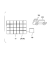
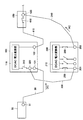
- FIG. 1 is a block diagram for explaining the configuration of the photovoltaic power generation system according to the first embodiment of the present invention.
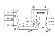
- 2 and 3 are block diagrams for explaining the configuration of the power converter used in the solar power generation system according to the first embodiment of the present invention.
- the photovoltaic power generation system includes a plurality of solar cell arrays 10, a connection box 20 that combines wirings from the solar cell array 10, and wirings from the connection box 20.
- the current collecting box 50, the power converter 100 that converts the DC power output from the solar cell array 10 into AC power and outputs the AC power, and the AC power output from the power converter 100 are combined.
- a step-up transformer 150 for boosting the voltage Note that the AC power boosted by the step-up transformer 150 is sent to the substation 160.
- the solar cell array 10 includes a plurality of solar cell modules that are electrically connected to each other. Each of the plurality of solar cell modules is configured by connecting a plurality of solar cells that are photoelectric conversion elements.
- connection box 20 is connected to a plurality of solar cell arrays 10, and has a function of collecting the output from the solar cell array 10 and outputting it to the current collection box 50.
- the current collection box 50 is connected to a plurality of connection boxes 20, and has a function of collecting the output from the connection box 20 and outputting it to the power converter 100. As shown in FIG. 2, the current collection box 50 is connected to the power conversion apparatus 100 via the DC cable 30. The current collection box 50 is provided with a connection terminal 51 to which the DC cable 30 is connected.
- a thick cable of about 150 sq is used for the DC cable 30 that connects the current collection box 50 and the power converter 100.
- the power conversion device 100 is composed of a power conversion device with a rated output of 250 kW used for industrial or solar power plants. Since generally 1 to 3 current collection boxes are connected to a power converter having a rated output of 250 kW, in the first embodiment, the power converter 100 includes three current collection boxes 50. It is assumed that it can be connected.
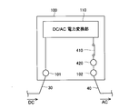
- the power conversion apparatus 100 includes a connection terminal 101 to which the DC cable 30 is connected and an inverter that converts DC power from the solar cell array 10 (see FIG. 1) into AC power.
- the power converter 110 includes an AC output terminal 102 for outputting AC power converted by the power converter 110.
- the DC cable 30 is an example of the “first electric wiring” and the “electric wiring” in the present invention.
- the connection terminals 51 and 101 are examples of the “first terminal” in the present invention, and the AC output terminal 102 is an example of the “second terminal” in the present invention.
- the three power collection boxes 50 are connected to the power conversion device 100 via the DC cable 30.
- the power converter 100 is provided with the three connection terminals 101 to which the DC cable 30 is connected.
- an AC cable 40 is connected to the AC output terminal 102 of the power converter 100, and the power converter 100 and the step-up transformer 150 are connected to each other via the AC cable 40.
- the AC cable 40 is an example of the “second electrical wiring” in the present invention.
- each of the connection boxes 20 can normally connect 10 or more solar cell arrays 10
- each of the current collection boxes 50 can normally connect 10 or more connection boxes. Is possible.
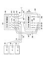
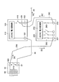
- the said power converter device 100 can isolate
- the switch 410 and maintenance connection terminals 320 and 420 are further provided.
- the switches 310 and 410 are examples of the “first switch” and the “second switch” of the present invention, respectively, and the connection terminals 320 and 420 for maintenance are respectively the “first switch” of the present invention. It is an example of a “connection terminal” and a “second connection terminal”.
- the maintenance connection terminal 320 and the switch 310 are provided three by three so as to correspond to the connection terminal 101 to which the DC cable 30 is connected.
- the maintenance connection terminal 420 and the switch 410 Is provided so as to correspond to the AC output terminal 102.
- the maintenance connection terminals 320 are configured to have the same potential as the DC cable 30 by being electrically connected to the connection terminals 101, respectively. Further, the three connection terminals 320 for maintenance are respectively connected to the input side of the power conversion unit 110 via the switch 310. On the other hand, the connection terminal 420 for maintenance is electrically connected to the AC output terminal 102 and is connected to the output side of the power conversion unit 110 via the switch 410.
- the maintenance connection terminals 320 and 420 in the power conversion apparatus 100 are connected to alternative power conversion apparatuses described later.
- the connection terminals 320 and 420 are preferably dedicated connectors, and more preferably have a shape that can be connected only to a dedicated plug. Further, it is more preferable that the dedicated connector and the dedicated plug are completely insulated and configured so that a person cannot directly touch the terminal.
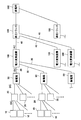
- FIG. 4 and 5 are diagrams for explaining a maintenance method (work procedure at the time of maintenance) of the power conversion device in the photovoltaic power generation system according to the first embodiment of the present invention.
- a maintenance method work procedure at the time of maintenance
- FIG. 1 FIG. 1
- FIG. 4 and FIG. 5 the operation procedure (failure recovery method) at the time of maintenance of the power conversion device in the photovoltaic power generation system according to the first embodiment of the present invention will be described.
- a 4-ton truck (moving means) 700 is loaded with an alternative power converter 200 with a rated output of 250 kW and a power plant (power requiring maintenance). Go near the converter 100).
- the alternative power conversion device 200 in addition to the connection terminal 201 to which the DC cable 230 is connected and the AC output terminal 202 to which the AC cable 240 is connected, the solar power to the power conversion unit 210 A switch 250 that cuts off the output from the battery array 10 (see FIG. 1) and a switch 260 that can disconnect the power conversion unit 110 and the AC output terminal 102 may be provided.
- the switches 310 and 410 are opened, so that the output of the solar cell array 10 (see FIG. 1) is output from the power conversion unit 110 inside the power conversion device 100. Separate.
- the DC cable 230 from the alternative power conversion device 200 is connected to the maintenance connection terminal 320 provided in the power conversion device 100, and the maintenance connection terminal 420 provided in the power conversion device 100 is substituted.
- the AC cable 240 from the power converter 200 is connected.
- the connection terminal 320 is preferably a dedicated connector that can be connected only to the DC cable 230 from the alternative power converter 200, and the connection terminal 420 is connected from the alternative power converter 200.
- a dedicated connector that can be connected only to the AC cable 240 is preferable.
- the alternative power conversion device 200 preferably has a function of diagnosing the state of the power conversion device 100 (power conversion unit 110).
- the alternative power conversion device 200 is disconnected. Then, by closing the switches 310 and 410 of the power conversion device 100, power is sent to the power conversion unit 110 in the power conversion device 100 to perform power conversion.
- the solar cell array 10 to the power converter 110 is provided.
- the output from can be cut off.
- the connection terminals 320 and 420 for maintenance in the power converter 100 by connecting the alternative power converter 200 to the connection terminals 320 and 420, the path of the DC power from the solar cell array 10 is Switching to the alternative power conversion device 200 is possible. Thereby, the maintenance operation
- maintenance work can be performed without removing the DC cable 30 that connects the current collection box 50 and the power conversion device 100.
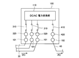
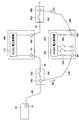
- FIG. 6 is a block diagram for explaining a photovoltaic power generation system according to the second embodiment of the present invention.
- FIG. 7 is a block diagram of a power converter used in the solar power generation system according to the second embodiment of the present invention.
- FIG. 8 is a block diagram of a current collection box used in the solar power generation system according to the second embodiment of the present invention.
- a photovoltaic power generation system according to a second embodiment of the present invention will be described with reference to FIGS.
- 2nd Embodiment demonstrates the case where the power converter device of rated output 100kW is used.
- symbol is attached
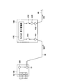
- a switch 310 that cuts off the output from the solar cell array to the power converter 110 is provided in the power converter 100, and is used for maintenance.
- a connection terminal 320 is provided in the current collection box 50. That is, in the second embodiment, the power conversion device 100 is not provided with the connection terminal 320 for maintenance, and the connection terminal 320 for maintenance is provided in the current collection box 50.
- the power conversion device 100 connects one current collection box 50. It is assumed that it can be configured. For this reason, one power collection box 50 is connected to the power converter 100 via the DC cable 30.
- the current collection box 50 is provided with one connection terminal 51 to which the DC cable 30 is connected, and the power converter 100 is provided with one connection terminal 101 to which the DC cable 30 is connected. It has been.
- the connection terminal 101 is connected to the power conversion unit 110 via the switch 310.
- the power conversion device 100 according to the second embodiment is similar to the first embodiment in that the AC output terminal 102, the switch 410 that can disconnect the power conversion unit 110 and the AC output terminal 102, and the connection for maintenance are provided.
- the terminal 420 is also provided.
- the AC output terminal 102 is electrically connected to the maintenance connection terminal 420, and the maintenance connection terminal 420 is connected to the output side of the power conversion unit 110 via the switch 410. It is connected to the.
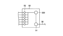
- connection terminal 320 for maintenance provided in the current collection box 50 is electrically connected to the connection terminal 51, as shown in FIG. 8, whereby the connection terminal 320 for maintenance is connected to the DC cable. 30 and the same potential.
- the current collection box 50 is provided with a connection terminal 52 for connecting a plurality of connection boxes 20 (see FIG. 1), and the connection terminal 51 and the connection terminal are connected via the connection terminal 320 for maintenance. 52 is connected.
- FIG. 9 is a block diagram for explaining a maintenance method (work procedure at the time of maintenance) of the power conversion device in the photovoltaic power generation system according to the second embodiment of the present invention.
- a maintenance method work procedure at the time of maintenance
- FIG. 4 and FIG. 9 the work procedure at the time of the maintenance of the power converter device in the photovoltaic power generation system by 2nd Embodiment of this invention is demonstrated.
- the 4-ton truck 700 is loaded with the alternative power converter 200 with a rated output of 250 kW and goes to the power plant.
- the alternative power conversion device 200 an alternative power conversion device with a rated output of 100 kW may be used.
- the switches 310 and 410 are opened, so that the output of the solar cell array is converted into the power conversion unit 110 inside the power conversion device 100. Disconnect from.
- the DC cable 230 from the alternative power conversion device 200 is connected to the maintenance connection terminal 320 provided in the current collection box 50, and the maintenance connection terminal 420 provided in the power conversion device 100 is substituted.
- the AC cable 240 from the power converter 200 is connected.
- the alternative power conversion device 200 is disconnected. Then, by closing the switches 310 and 410 of the power conversion device 100, power is sent to the power conversion unit 110 in the power conversion device 100 to perform power conversion.
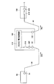
- FIG. 10 is a block diagram for explaining a photovoltaic power generation system according to the third embodiment of the present invention.
- FIG. 11 is a block diagram of a power converter used in the solar power generation system according to the third embodiment of the present invention.
- FIG. 12 is a block diagram of a current collection box used in the solar power generation system according to the third embodiment of the present invention.
- a solar power generation system according to a third embodiment of the present invention will be described with reference to FIGS.
- a case where a power conversion device with a rated output of 100 kW is used will be described.
- symbol is attached
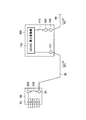
- a switch 310 that shuts off the output from the solar cell array to the power converter 110 and a connection terminal 320 for maintenance are provided in the current collecting box 50. Is provided. That is, in the third embodiment, the power conversion device 100 is configured such that the maintenance connection terminal 320 and the switch 310 are not provided.
- the power conversion device 100 includes an AC output terminal 102, a switch 410 that can disconnect the power conversion unit 110 and the AC output terminal 102, and maintenance.
- the connection terminal 420 is also provided.
- the switch 310 is disposed between the connection terminal 320 for maintenance and the connection terminal 51 to which the DC cable 30 is connected. That is, the connection terminal 320 for maintenance is connected to the connection terminal 51 to which the DC cable 30 is connected via the switch 310.
- FIG. 13 is a block diagram for explaining a maintenance method (work procedure at the time of maintenance) of the power conversion device in the photovoltaic power generation system according to the third embodiment of the present invention.
- a maintenance method work procedure at the time of maintenance
- FIG. 4 and FIG. 13 the work procedure at the time of the maintenance of the power converter device in the solar power generation system according to the third embodiment of the present invention will be described.
- the 4-ton truck 700 is loaded with the alternative power converter 200 with a rated output of 250 kW and goes to the power plant.
- the alternative power conversion device 200 an alternative power conversion device with a rated output of 100 kW may be used.
- the switch 310 of the current collection box 50 is opened, and the switch 410 of the power converter 100 that requires maintenance is opened so that the output of the solar cell array can be obtained. Is disconnected from the power converter 110 inside the power converter 100.
- the DC cable 230 from the alternative power conversion device 200 is connected to the maintenance connection terminal 320 provided in the current collection box 50, and the maintenance connection terminal 420 provided in the power conversion device 100 is substituted.
- the AC cable 240 from the power converter 200 is connected.
- the alternative power conversion device 200 is disconnected. Then, by closing the switch 310 of the current collection box 50 and the switch 410 of the power converter 100, power is sent to the power converter 110 in the power converter 100 to perform power conversion.
- the effect of the third embodiment is the same as that of the first embodiment.
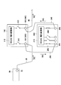
- FIG. 14 is a block diagram for explaining a photovoltaic power generation system according to the fourth embodiment of the present invention.
- the photovoltaic power generation system by 4th Embodiment of this invention is demonstrated.
- the fourth embodiment as in the second and third embodiments, a case where a power converter having a rated output of 100 kW is used will be described.
- symbol is attached
- a first terminal box 350 having a connection terminal 320 for maintenance is connected between the current collection box 50 and the power converter 100.
- the first terminal box 350 is provided with a switch 310 that cuts off the output from the solar cell array to the power converter 110 together with the connection terminal 320.
- the maintenance connection terminal 320 is connected to the power conversion unit 110 of the power conversion device 100 via the switch 310.
- a connection box (second terminal box 450) similar to the first terminal box 350 is also connected between the power converter 100 and the step-up transformer 150.
- the second terminal box 450 is provided with a connection terminal 420 and a switch 410 for maintenance.
- the maintenance connection terminal 420 is connected to the power conversion unit 110 of the power conversion device 100 via the switch 410.
- neither the power conversion device 100 nor the current collection box 50 is provided with a maintenance connection terminal and a switch.
- FIG. 15 is a block diagram for explaining a maintenance method (work procedure at the time of maintenance) of the power conversion device in the photovoltaic power generation system according to the fourth embodiment of the present invention.
- a maintenance method work procedure at the time of maintenance
- FIG. 4 and FIG. 15 the work procedure at the time of the maintenance of the power converter device in the solar power generation system by 4th Embodiment of this invention is demonstrated.
- the 4-ton truck 700 is loaded with the alternative power converter 200 with a rated output of 250 kW and goes to the power plant.
- the alternative power conversion device 200 an alternative power conversion device with a rated output of 100 kW may be used.
- the output of the solar cell array is set inside the power converter 100. Disconnect from the power converter 110.
- the DC cable 230 from the alternative power converter 200 is connected to the maintenance connection terminal 320 provided in the first terminal box 350, and the maintenance connection terminal 420 provided in the second terminal box 450 is connected.
- the AC cable 240 from the alternative power conversion device 200 is connected.
- the alternative power conversion device 200 is disconnected. And by making the switch 310 of the 1st terminal box 350 and the switch 410 of the 2nd terminal box 450 into a closed state, electric power is sent to the power conversion part 110 in the power converter device 100, and power conversion is performed.
- the effect of the fourth embodiment is the same as that of the first embodiment.
- FIG. 16 is a block diagram for explaining a photovoltaic power generation system according to a fifth embodiment of the present invention.
- the photovoltaic power generation system by 5th Embodiment of this invention is demonstrated.
- symbol is attached
- a maintenance connection terminal 420 and a switch 410 are provided in a step-up transformer 150 that steps up AC power output from the power converter 100. ing.
- the switch 410 is disposed between the power conversion unit 110 and the maintenance connection terminal 420 so that the power conversion unit 110 and the maintenance connection terminal 420 can be disconnected.
- the fifth embodiment since the step-up transformer 150 connected to the output side of the power converter 100 is provided with the switch 410 and the connection terminal 420 for maintenance, the fifth embodiment is different from the first to third embodiments. In contrast, a switch and a connection terminal for maintenance are not provided between the power conversion unit 110 and the AC output terminal 102 in the power conversion device 100.
- FIG. 17 is a block diagram for explaining a maintenance method (work procedure at the time of maintenance) of the power conversion device in the photovoltaic power generation system according to the fifth embodiment of the present invention.
- a maintenance method work procedure at the time of maintenance
- FIG. 4 and FIG. 17 the work procedure at the time of the maintenance of the power converter device in the solar power generation system according to the fifth embodiment of the present invention will be described.
- the 4-ton truck 700 is loaded with the alternative power converter 200 with a rated output of 250 kW and goes to the power plant.
- the alternative power conversion device 200 an alternative power conversion device with a rated output of 100 kW may be used.
- the switch 310 of the power conversion device 100 requiring maintenance is opened, and the switch 410 of the step-up transformer 150 is opened so that the output of the solar cell array is Disconnect from the power converter 110 inside the power converter 100.
- the DC cable 230 from the alternative power converter 200 is connected to the maintenance connection terminal 320 provided in the power converter 100, and the alternative power is connected to the maintenance connection terminal 420 provided in the step-up transformer 150.
- the AC cable 240 from the conversion device 200 is connected.
- the alternative power conversion device 200 is disconnected. Then, by closing the switch 310 of the power converter 100 and the switch 410 of the step-up transformer 150, power is sent to the power converter 110 in the power converter 100 to perform power conversion.
- the effect of the fifth embodiment is the same as that of the first embodiment.
- FIG. 18 is a block diagram for explaining a photovoltaic power generation system according to a sixth embodiment of the present invention.
- the photovoltaic power generation system by 6th Embodiment of this invention is demonstrated.
- symbol is attached
- connection terminal 101 to which the DC cable 30 is connected and the connection terminal (the AC output terminal 102) to which the AC cable 40 is connected are respectively It also serves as the connection terminals 320 and 420 for maintenance.
- the power conversion device 100 is provided with a switch 310 that cuts off the output from the solar cell array to the power conversion unit 110, and a switch 410 that can disconnect the power conversion unit 110 and the AC output terminal 102. It has been. Thereby, it becomes possible to isolate
- FIG. 19 is a block diagram for explaining a maintenance method (work procedure at the time of maintenance) of the power conversion device in the photovoltaic power generation system according to the sixth embodiment of the present invention.
- a maintenance method work procedure at the time of maintenance
- FIG. 4 and FIG. 19 the work procedure at the time of the maintenance of the power converter device in the solar power generation system according to the sixth embodiment of the present invention will be described.
- the 4-ton truck 700 is loaded with the alternative power converter 200 with a rated output of 250 kW and goes to the power plant.
- the alternative power conversion device 200 an alternative power conversion device with a rated output of 100 kW may be used.
- the DC cable 230 from the alternative power converter 200 is connected to the connection terminal 101 (320) provided in the power converter 100, and the AC output terminal 102 (420) provided in the power converter 100 is connected.
- the AC cable 240 from the alternative power conversion device 200 is connected.
- the alternative power conversion device 200 is disconnected. Then, by closing the switches 310 and 410 of the power conversion device 100, power is sent to the power conversion unit 110 in the power conversion device 100 to perform power conversion.
- the effect of the sixth embodiment is the same as that of the first embodiment.
- FIG. 20 is a block diagram for explaining a photovoltaic power generation system according to a seventh embodiment of the present invention.
- the photovoltaic power generation system by 7th Embodiment of this invention is demonstrated.
- the seventh embodiment as in the second to sixth embodiments, a case where a power converter having a rated output of 100 kW is used will be described.
- symbol is attached
- connection terminal 51 of the current collection box 50 also serves as the connection terminal 320 for maintenance. Therefore, during the maintenance of the power conversion device 100, the DC cable 230 from the alternative power conversion device 200 is connected to the connection terminal 51 (320) of the current collection box 50.
- the effect of the seventh embodiment is the same as that of the first and sixth embodiments.
- FIG. 21 is a block diagram for explaining a photovoltaic power generation system according to an eighth embodiment of the present invention.
- the solar power generation system by 8th Embodiment of this invention is demonstrated.
- a case where a power converter with a rated output of 100 kW is used as in the second to seventh embodiments will be described.
- symbol is attached
- the power converter 100 is provided with a connection terminal 320 for maintenance.
- the switch 310 includes a changeover switch.
- the changeover switch 310 has a function of switching the connection destination of the connection terminal 101 to which the DC cable 30 is connected to the power conversion unit 110 or the connection terminal 320 for maintenance. For this reason, the changeover switch 310 switches the supply destination of the DC power from the solar cell array to the power conversion unit 100 or the connection terminal 320 for maintenance.
- the changeover switch 310 when the changeover switch 310 is connected to the power conversion unit 110, power from the solar cell array is supplied to the power conversion unit 110 and is not supplied to the connection terminal 320 for maintenance. ing.
- the connection of the changeover switch 310 is switched to the connection terminal 320 for maintenance, the output from the solar cell array to the power conversion unit 110 is cut off, and the DC power from the solar cell array is supplied to the connection terminal 320 for maintenance. Supplied.
- the DC cable 230 from the alternative power conversion device 200 is connected to the maintenance connection terminal 320 in a state where the changeover switch 310 is connected to the power conversion unit 110, a solar cell is connected to the maintenance connection terminal 320. Since power from the array is not supplied, the DC cable 230 can be connected safely. If the changeover switch 310 is switched to the maintenance connection terminal 320 after the connection of the DC cable 230, the output from the solar cell array to the power conversion unit 110 is cut off, and the DC power from the solar cell array is substituted. It is supplied to the power converter 200. Thereby, the power conversion which the power converter device 100 should bear can be made to bear the alternative power converter device 200.
- the present invention is applied to the solar power generation system for the solar power plant.
- the present invention is not limited to this, and the present invention is not limited to this.
- the present invention can also be applied to other solar power generation systems and household solar power generation systems.
- the alternative power conversion device is mounted on a 4-ton truck and transported to the vicinity of the power conversion device requiring maintenance.
- the moving means for mounting the alternative power conversion device may be a truck vehicle other than the 4-ton truck. Further, it may be a moving means other than a truck vehicle. For example, a configuration in which an alternative power conversion device is mounted on a cart and towed by a motorcycle may be used.
- connection terminals may be provided. By comprising in this way, an additional member can be reduced.
- a switch may not be provided on the output side of the power conversion unit in the power converter.
- the present invention is not limited thereto, and the power conversion device used in the solar power generation system is used. May be a power converter other than the rated output of 100 kW (for example, a power converter having a rated output of 250 kW).
- the capacity of the power converter is increased, the size of the power converter inevitably increases, and the shadow of the power converter affects the solar cell array. For this reason, the capacity of the power conversion device is not so large, and is about 100 kW to 1 MW.
- breakers which are safety parts used in power converters
- rated output of 100 kW and 250 kW are widely used for industrial use as power converters.
- power converters for industrial or solar power plants rated outputs of 100 kW and 250 kW are generally used, but the present invention is effectively applied even when power converters other than these are used. can do.
- the alternative power conversion device can be appropriately selected according to the power conversion device requiring maintenance.
- a terminal box may be provided between the current collection box and the power converter and between the power converter and the step-up transformer.
- connection terminal for maintenance is provided in the step-up transformer.
- the present invention is not limited to this, and the connection terminal originally provided in the step-up transformer is used as the connection terminal for maintenance. You may also use as.
- the step-up transformer is provided with a switch together with a connection terminal for maintenance.
- the present invention is not limited to this, and the step-up transformer is not provided with a switch. Also good.
- the switch which consists of a change switch in the said 8th Embodiment in the power converter device
- this invention is not limited to this,
- the said switch is provided in locations other than a power converter device.
- the changeover switch may be provided in a current collection box, or when the terminal box (first terminal box) is provided between a power converter and a current collection box, It may be provided.
- connection terminal (AC output terminal) to which the AC cable is connected serves as a maintenance connection terminal.
- the AC output terminal and the maintenance connection terminal are separately provided. It can also be provided.
- a switch (second switch) capable of separating the power conversion unit and the AC output terminal can also be a changeover switch similar to the above. That is, not only the switch on the input side of the power conversion unit (first switch) but also the switch on the output side of the power conversion unit (second switch) can be the same changeover switch.
Landscapes
- Engineering & Computer Science (AREA)
- Power Engineering (AREA)
- Photovoltaic Devices (AREA)
- Inverter Devices (AREA)
- Supply And Distribution Of Alternating Current (AREA)
Priority Applications (1)
| Application Number | Priority Date | Filing Date | Title |
|---|---|---|---|
| US13/640,898 US20130026844A1 (en) | 2010-04-12 | 2011-03-25 | Photovoltaic generation system, power conversion device, and collector box |
Applications Claiming Priority (2)
| Application Number | Priority Date | Filing Date | Title |
|---|---|---|---|
| JP2010091454A JP5453158B2 (ja) | 2010-04-12 | 2010-04-12 | 太陽光発電システム、電力変換装置および集電箱 |
| JP2010-091454 | 2010-04-12 |
Publications (1)
| Publication Number | Publication Date |
|---|---|
| WO2011129188A1 true WO2011129188A1 (ja) | 2011-10-20 |
Family
ID=44798566
Family Applications (1)
| Application Number | Title | Priority Date | Filing Date |
|---|---|---|---|
| PCT/JP2011/057312 Ceased WO2011129188A1 (ja) | 2010-04-12 | 2011-03-25 | 太陽光発電システム、電力変換装置および集電箱 |
Country Status (3)
| Country | Link |
|---|---|
| US (1) | US20130026844A1 (enExample) |
| JP (1) | JP5453158B2 (enExample) |
| WO (1) | WO2011129188A1 (enExample) |
Cited By (1)
| Publication number | Priority date | Publication date | Assignee | Title |
|---|---|---|---|---|
| WO2012098392A1 (en) * | 2011-01-18 | 2012-07-26 | Enecsys Limited | Solar photovoltaic systems |
Families Citing this family (5)
| Publication number | Priority date | Publication date | Assignee | Title |
|---|---|---|---|---|
| JP5897974B2 (ja) * | 2012-04-24 | 2016-04-06 | 三菱電機株式会社 | 電力変換器 |
| JP2014107370A (ja) * | 2012-11-27 | 2014-06-09 | Sumiden Asahi Industries Ltd | グリーン電力システムの送電線路 |
| JP6271306B2 (ja) * | 2014-03-17 | 2018-01-31 | シャープ株式会社 | 太陽光発電システム |
| US9444304B2 (en) * | 2014-07-21 | 2016-09-13 | Caterpillar Inc. | Generator set having adjustable terminal box |
| US10417628B2 (en) * | 2016-06-29 | 2019-09-17 | Square, Inc. | Multi-interface processing of electronic payment transactions |
Citations (3)
| Publication number | Priority date | Publication date | Assignee | Title |
|---|---|---|---|---|
| JP2000112545A (ja) * | 1998-09-30 | 2000-04-21 | Daihen Corp | 太陽光発電システム |
| WO2008144554A2 (en) * | 2007-05-17 | 2008-11-27 | Larankelo, Inc. | Photovoltaic ac inverter mount and interconnect |
| JP2010279234A (ja) * | 2009-06-01 | 2010-12-09 | Sumitomo Electric Ind Ltd | 太陽光発電装置 |
Family Cites Families (6)
| Publication number | Priority date | Publication date | Assignee | Title |
|---|---|---|---|---|
| WO2004100344A2 (en) * | 2003-05-02 | 2004-11-18 | Ballard Power Systems Corporation | Method and apparatus for tracking maximum power point for inverters in photovoltaic applications |
| US20100109601A1 (en) * | 2008-11-03 | 2010-05-06 | Coyle Eugene M | Portable solar electrical generator and water filtration and desalination system |
| US20100188042A1 (en) * | 2009-01-29 | 2010-07-29 | Ming-Hsiang Yeh | Electrical power transmission apparatus |
| US20110090607A1 (en) * | 2009-10-20 | 2011-04-21 | Luebke Charles J | String and system employing direct current electrical generating modules and a number of string protectors |
| DE202009016164U1 (de) * | 2009-11-26 | 2010-03-04 | Carlo Gavazzi Services Ag | Steuerungsvorrichtung für Fotovoltaikmodule |
| US8218274B2 (en) * | 2009-12-15 | 2012-07-10 | Eaton Corporation | Direct current arc fault circuit interrupter, direct current arc fault detector, noise blanking circuit for a direct current arc fault circuit interrupter, and method of detecting arc faults |
-
2010
- 2010-04-12 JP JP2010091454A patent/JP5453158B2/ja active Active
-
2011
- 2011-03-25 US US13/640,898 patent/US20130026844A1/en not_active Abandoned
- 2011-03-25 WO PCT/JP2011/057312 patent/WO2011129188A1/ja not_active Ceased
Patent Citations (3)
| Publication number | Priority date | Publication date | Assignee | Title |
|---|---|---|---|---|
| JP2000112545A (ja) * | 1998-09-30 | 2000-04-21 | Daihen Corp | 太陽光発電システム |
| WO2008144554A2 (en) * | 2007-05-17 | 2008-11-27 | Larankelo, Inc. | Photovoltaic ac inverter mount and interconnect |
| JP2010279234A (ja) * | 2009-06-01 | 2010-12-09 | Sumitomo Electric Ind Ltd | 太陽光発電装置 |
Cited By (3)
| Publication number | Priority date | Publication date | Assignee | Title |
|---|---|---|---|---|
| WO2012098392A1 (en) * | 2011-01-18 | 2012-07-26 | Enecsys Limited | Solar photovoltaic systems |
| US9276409B2 (en) | 2011-01-18 | 2016-03-01 | Solarcity Corporation | Solar photovoltaic systems |
| US10418818B2 (en) | 2011-01-18 | 2019-09-17 | Tesla, Inc. | Solar photovoltaic systems |
Also Published As
| Publication number | Publication date |
|---|---|
| JP5453158B2 (ja) | 2014-03-26 |
| JP2011222820A (ja) | 2011-11-04 |
| US20130026844A1 (en) | 2013-01-31 |
Similar Documents
| Publication | Publication Date | Title |
|---|---|---|
| Saeedifard et al. | DC power systems: Challenges and opportunities | |
| US8642879B2 (en) | System for coupling photovoltaic arrays | |
| CN1902808B (zh) | 分散型发电系统及其操作方法 | |
| CN100521471C (zh) | Dc/dc转换器和包括dc/dc转换器的分散型发电系统 | |
| US8901773B2 (en) | Power supply system and photovoltaic device therefor | |
| JPWO2012046331A1 (ja) | 故障検出装置 | |
| JP5453158B2 (ja) | 太陽光発電システム、電力変換装置および集電箱 | |
| JP5377018B2 (ja) | 太陽光発電システム | |
| US8648498B1 (en) | Photovoltaic power system with distributed photovoltaic string to polyphase AC power converters | |
| US20140117770A1 (en) | Power converter | |
| Komilov | Power of network photoelectric power stations | |
| KR20170053033A (ko) | 하이브리드 배전망 시스템 | |
| KR20110074370A (ko) | 발전량에 따른 전력제어방법 및 그 전력변환장치 | |
| KR101742600B1 (ko) | 무정전 기능을 가진 수배전반 | |
| KR20240134295A (ko) | 전력 공급 조절 가능한 분산형 확장 가능한 태양광 발전 시스템 | |
| CN102780233A (zh) | 一种大规模分布式光伏电站用户侧并网防逆流系统 | |
| CN217183035U (zh) | 一种级联式储能系统 | |
| KR20150007138A (ko) | 계통 연계형 태양광 발전 시스템의 배터리 충전 장치 | |
| CN214280955U (zh) | 一种中压光伏逆变系统及光伏发电系统 | |
| CN211930585U (zh) | 一种集中式光伏逆变系统 | |
| KR101737970B1 (ko) | 하이브리드 수배전반 | |
| JP2012222973A (ja) | 無停電電源システム | |
| CN202678969U (zh) | 一种风力发电机微网供电电源系统 | |
| CN108173518B (zh) | 一种光伏发电监控装置及方法 | |
| CN202488382U (zh) | 应用建模的太阳能光伏电站 |
Legal Events
| Date | Code | Title | Description |
|---|---|---|---|
| 121 | Ep: the epo has been informed by wipo that ep was designated in this application |
Ref document number: 11768709 Country of ref document: EP Kind code of ref document: A1 |
|
| NENP | Non-entry into the national phase |
Ref country code: DE |
|
| WWE | Wipo information: entry into national phase |
Ref document number: 13640898 Country of ref document: US |
|
| 122 | Ep: pct application non-entry in european phase |
Ref document number: 11768709 Country of ref document: EP Kind code of ref document: A1 |