WO2011129163A1 - イントラ予測処理方法、及びイントラ予測処理プログラム - Google Patents
イントラ予測処理方法、及びイントラ予測処理プログラム Download PDFInfo
- Publication number
- WO2011129163A1 WO2011129163A1 PCT/JP2011/055327 JP2011055327W WO2011129163A1 WO 2011129163 A1 WO2011129163 A1 WO 2011129163A1 JP 2011055327 W JP2011055327 W JP 2011055327W WO 2011129163 A1 WO2011129163 A1 WO 2011129163A1
- Authority
- WO
- WIPO (PCT)
- Prior art keywords
- prediction mode
- prediction
- processing
- image
- intra
- Prior art date
- Legal status (The legal status is an assumption and is not a legal conclusion. Google has not performed a legal analysis and makes no representation as to the accuracy of the status listed.)
- Ceased
Links
Images








Classifications
-
- H—ELECTRICITY
- H04—ELECTRIC COMMUNICATION TECHNIQUE
- H04N—PICTORIAL COMMUNICATION, e.g. TELEVISION
- H04N19/00—Methods or arrangements for coding, decoding, compressing or decompressing digital video signals
- H04N19/10—Methods or arrangements for coding, decoding, compressing or decompressing digital video signals using adaptive coding
- H04N19/102—Methods or arrangements for coding, decoding, compressing or decompressing digital video signals using adaptive coding characterised by the element, parameter or selection affected or controlled by the adaptive coding
- H04N19/103—Selection of coding mode or of prediction mode
- H04N19/11—Selection of coding mode or of prediction mode among a plurality of spatial predictive coding modes
-
- H—ELECTRICITY
- H04—ELECTRIC COMMUNICATION TECHNIQUE
- H04N—PICTORIAL COMMUNICATION, e.g. TELEVISION
- H04N19/00—Methods or arrangements for coding, decoding, compressing or decompressing digital video signals
- H04N19/10—Methods or arrangements for coding, decoding, compressing or decompressing digital video signals using adaptive coding
- H04N19/134—Methods or arrangements for coding, decoding, compressing or decompressing digital video signals using adaptive coding characterised by the element, parameter or criterion affecting or controlling the adaptive coding
- H04N19/136—Incoming video signal characteristics or properties
-
- H—ELECTRICITY
- H04—ELECTRIC COMMUNICATION TECHNIQUE
- H04N—PICTORIAL COMMUNICATION, e.g. TELEVISION
- H04N19/00—Methods or arrangements for coding, decoding, compressing or decompressing digital video signals
- H04N19/10—Methods or arrangements for coding, decoding, compressing or decompressing digital video signals using adaptive coding
- H04N19/134—Methods or arrangements for coding, decoding, compressing or decompressing digital video signals using adaptive coding characterised by the element, parameter or criterion affecting or controlling the adaptive coding
- H04N19/146—Data rate or code amount at the encoder output
- H04N19/147—Data rate or code amount at the encoder output according to rate distortion criteria
-
- H—ELECTRICITY
- H04—ELECTRIC COMMUNICATION TECHNIQUE
- H04N—PICTORIAL COMMUNICATION, e.g. TELEVISION
- H04N19/00—Methods or arrangements for coding, decoding, compressing or decompressing digital video signals
- H04N19/10—Methods or arrangements for coding, decoding, compressing or decompressing digital video signals using adaptive coding
- H04N19/169—Methods or arrangements for coding, decoding, compressing or decompressing digital video signals using adaptive coding characterised by the coding unit, i.e. the structural portion or semantic portion of the video signal being the object or the subject of the adaptive coding
- H04N19/17—Methods or arrangements for coding, decoding, compressing or decompressing digital video signals using adaptive coding characterised by the coding unit, i.e. the structural portion or semantic portion of the video signal being the object or the subject of the adaptive coding the unit being an image region, e.g. an object
- H04N19/176—Methods or arrangements for coding, decoding, compressing or decompressing digital video signals using adaptive coding characterised by the coding unit, i.e. the structural portion or semantic portion of the video signal being the object or the subject of the adaptive coding the unit being an image region, e.g. an object the region being a block, e.g. a macroblock
-
- H—ELECTRICITY
- H04—ELECTRIC COMMUNICATION TECHNIQUE
- H04N—PICTORIAL COMMUNICATION, e.g. TELEVISION
- H04N19/00—Methods or arrangements for coding, decoding, compressing or decompressing digital video signals
- H04N19/50—Methods or arrangements for coding, decoding, compressing or decompressing digital video signals using predictive coding
- H04N19/593—Methods or arrangements for coding, decoding, compressing or decompressing digital video signals using predictive coding involving spatial prediction techniques
Definitions
- the present invention relates to an intra prediction processing method and an intra prediction processing program for predicting a corresponding prediction block from an adjacent block according to a prediction mode for a processing target block composed of a plurality of pixels for use in predictive encoding of an input image.
- prediction encoding techniques such as encoding by intra prediction processing for performing prediction within the same frame and inter prediction encoding for performing prediction between temporally continuous frames are known.
- H.264 H.264/ MPEG-4 AVC (hereinafter referred to as H.264) encoder is configured as shown in FIG.
- intra prediction processing unit 2 of the H.264 encoder 1 intra prediction processing for determining a prediction pattern from adjacent blocks is executed.
- a processing target block composed of a plurality of pixels is set in an input image, and a corresponding prediction block is predicted from an adjacent block, and a prediction encoding process is performed based on this prediction.
- the image of the processing target block is estimated to be close to the image of the adjacent block, and is predicted from the adjacent block.
- the plurality of prediction modes mainly indicate in which direction the adjacent block is closer, but it is not known in advance which prediction mode (prediction direction) will improve the prediction accuracy.
- the intra prediction processing method is known as a process with a large amount of calculation, and therefore, reduction of the calculation amount for determining the prediction mode in the intra prediction processing method has been studied as an important technical problem.
- Patent Document 1 proposes a method of narrowing down the prediction mode with reference to the prediction mode of an adjacent block that has been encoded by intra prediction processing.
- the number of prediction mode candidates is limited according to the spatial position of the target block or the position on the time axis, and the amount of calculation for evaluating the prediction mode is reduced.
- a block that limits the number of prediction mode candidates in a certain block in an image is determined by external input.
- the number of modes to be limited is also given as an external input and is variable for each block.
- the candidate prediction mode is determined from the prediction modes of the encoded neighboring blocks with priorities.
- the intra prediction process for predictive coding has a large amount of calculation, and a method for reducing the process has been proposed.
- Patent Document 1 and Patent Document 2 have been studied in order to reduce the amount of calculation by narrowing down the number of prediction mode candidates.
- Patent Documents 1 and 2 have the following problems.
- the prediction mode itself of the encoded neighboring block that is referred to in order to limit prediction mode candidates is also the prediction mode determined in a limited manner as described above. For this reason, it is not known whether the optimum prediction mode has been determined.
- the method for limiting the prediction mode candidates depends on the processing contents in the encoded region or the characteristics specific to the input image to be processed. It could not be said that it could narrow down to the optimal prediction mode candidates.
- the present invention has been made in view of the above technical problems.
- the object of the present invention is to narrow down the prediction mode candidates to the optimal prediction mode easily and quickly without depending on the prediction mode of the encoded region and the characteristics specific to the processing target image in the predictive encoding process of the input image.
- the present invention has the following features.
- the intra prediction processing method includes: a processing block setting step for setting a processing processing block for encoding composed of a plurality of pixels of an input image; and a target block from which adjacent block in which direction.
- Prediction mode candidates for narrowing down a predetermined number of prediction mode candidates, which are interpolation patterns indicating whether to create a predicted image by interpolation, to a plurality of prediction mode candidates smaller than the predetermined number based on the resolution information of the processing target block From the prediction mode candidates limited in the limiting step and the prediction mode candidate limiting step, the prediction mode that minimizes the cost of prediction encoding is determined as the prediction mode used for prediction encoding, and the prediction encoding process is performed.
- the prediction image of the processing target block is After form, the intra prediction processing method is characterized in that and a predictive coding step of coding the current block using the predictive image.
- the intra prediction processing method in the prediction mode candidate limiting step, for the plurality of predetermined prediction mode candidates, based on the direction component of the resolution information corresponding to the direction indicated by each prediction mode candidate.
- the intra prediction processing method wherein the priority of the prediction mode candidates is determined to narrow down to limited prediction mode candidates.
- an optical characteristic of an imaging device that captures the input image is used as the resolution information.
- the intra prediction processing method according to the fourth aspect is the intra prediction processing method according to the third aspect, wherein the optical characteristic of the imaging device is MTF.
- the resolution information determined by the image processing content in the preprocessing of the input image is used.
- the intra prediction processing method which concerns on the aspect.
- the intra prediction processing method which concerns on a 6th aspect hold
- a prediction mode candidate holding step, and in the prediction mode determination step, the limited prediction mode candidates are set based on information of the prediction mode candidate table held for the same imaging system.
- An intra prediction processing program includes: a processing block setting step for setting a processing processing block for encoding composed of a plurality of pixels of an input image in a computer; and the processing target block as a neighboring block in any direction From this, the predetermined number of prediction mode candidates, which are interpolation patterns representing how to create a predicted image by interpolation, are narrowed down to a plurality of prediction mode candidates smaller than the predetermined number based on the resolution information of the processing target block.
- the prediction mode candidate prediction step and the prediction mode candidate limited in the prediction mode candidate limitation step is determined as a prediction mode to be used for prediction encoding, and the prediction mode with the lowest prediction encoding cost is determined, and the prediction code In the prediction mode determination step used for the conversion processing and the prediction mode determined in the prediction mode determination step.
- the intra prediction processing program is characterized in that and a predictive coding step of coding the current block using the predictive image.
- the intra prediction processing program according to the eighth aspect is based on the direction component of the resolution information corresponding to the direction indicated by each prediction mode candidate for the plurality of predetermined prediction mode candidates.
- the intra prediction processing program according to the seventh aspect is characterized by narrowing down to limited prediction mode candidates by determining the priority of the prediction mode candidates.
- An intra prediction processing program uses, in the prediction mode candidate limiting step, an optical characteristic of an imaging device that captures the input image as the resolution information.
- An intra prediction processing program uses, in the prediction mode candidate limiting step, an optical characteristic of an imaging device that captures the input image as the resolution information.
- the intra prediction processing program according to the tenth aspect is the intra prediction processing program according to the ninth aspect, wherein the optical characteristic of the imaging device is MTF.
- An intra prediction processing program uses the resolution information determined by the image processing content in the preprocessing of the input image in the prediction mode candidate limiting step.
- An intra prediction processing program according to the above aspect.
- An intra prediction processing program relates to a prediction mode in which the processing target block position and the prediction mode candidates limited in the prediction mode candidate limiting step are associated with the computer in the input image imaging system.
- a prediction mode candidate holding step for holding a candidate table is executed, and in the prediction mode determination step, the limited prediction mode candidates are set based on information in the prediction mode candidate table held for the same imaging system.
- An intra prediction processing program according to any one of the seventh to tenth aspects.
- the intra prediction processing method and the intra prediction processing program in predictive encoding processing of an input image, based on resolution information at the position of a processing target block in the input image, a plurality of predetermined prediction mode candidates are used. Narrow down to limited prediction mode candidates, and predict prediction blocks corresponding to the processing target block from neighboring blocks.
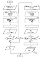
- FIG. 1 is a flowchart illustrating an example of a processing procedure of the intra prediction processing method according to the present embodiment.
- FIG. 2 is a block diagram illustrating a functional configuration example of an encoder that performs intra prediction processing.
- FIG. 3 is an explanatory view showing a target image example for explaining the intra prediction process.
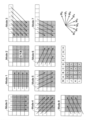
- FIG. 4 is a pattern diagram of the luminance signal intra 4 ⁇ 4 prediction mode.
- FIG. 5 is a pattern diagram of a luminance signal intra 16 ⁇ 16 prediction mode.
- FIG. 6 is a pattern diagram of an intra 8 ⁇ 8 prediction mode for color difference signals.
- FIG. 7 is a flowchart illustrating an example of a prediction mode determination procedure in the intra prediction process.
- FIG. 8 is a graph showing a typical example of the relationship between MTF and image height.
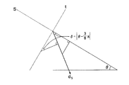
- FIG. 9 is a diagram illustrating the frequencies in the sagittal direction and the tangential direction when the arbitrary angle ⁇ is the frequency k.
- FIG. 10 is a diagram for explaining the outline of the prediction mode candidate limiting step in the form using an optical system (lens) for imaging.
- FIG. 11 is a diagram for illustrating the position of the processing target block in the target image.
- FIG. 12 is a diagram illustrating the directionality of the intra 4 ⁇ 4 prediction mode at the point (i, j).
- FIG. 13 is a diagram for explaining the calculation of the MTF in the d 0 direction.
- FIG. 14 is a diagram for explaining the calculation of the MTF in the d 1 direction.
- FIG. 15 is a diagram for explaining the calculation of the MTF in the d 5 direction.
- FIG. 16 is a diagram illustrating an example in which distortion is corrected by image processing.
- FIG. 1 is a flowchart illustrating an example of a schematic processing procedure of the intra prediction processing method according to the present embodiment. An example of a schematic processing procedure of the intra prediction processing method according to the present embodiment will be described with reference to FIG.
- the processing procedure of the intra prediction processing method described below is executed by applying an intra prediction processing program programmed to execute them to an information processing apparatus such as a computer.
- step S1 sets a processing target block composed of a plurality of pixels in the target image as a block to be subjected to predictive encoding processing by intra prediction of the input image.
- Step S2 calculates or acquires the direction component of resolution information (for example, MTF) at the set position of the processing target block in the input image.
- MTF is a Module Transfer Function, details of which will be described later.
- Step S3 is a prediction mode candidate limiting step, and a prediction mode candidate of a processing target block is determined according to the direction component of the resolution information (hereinafter referred to as MTF) obtained in step S2 from a plurality of predetermined prediction mode candidates. Limit.
- the prediction mode indicates a pattern for predicting a processing target block from an adjacent block, and a plurality of modes having different pattern directions are set as candidates. Details will be described later.
- the limited number of prediction mode candidates may be one or plural. In the present embodiment, description will be made assuming that the number of candidates is limited.
- Steps S4 to S6 are prediction mode determination steps, and for the prediction mode candidates limited in step S3, the prediction mode candidate that minimizes the cost of predictive coding is determined as the prediction mode.
- step S4 to step S6 the cost of predictive coding for each prediction mode candidate is evaluated.
- Step S4 calculates a prediction block by referring to an adjacent block according to the prediction mode for each prediction mode candidate limited in step S3 with respect to the set processing target block.
- Step S5 performs a cost calculation process of the processing target block using the prediction block calculated for each limited prediction mode candidate. This is for comparing the cost evaluation of prediction encoding for each prediction mode candidate.
- step S6 one prediction mode for the set processing target block is determined based on the cost evaluation result of the prediction encoding in step S5. That is, among the prediction mode candidates, the prediction mode candidate with the lowest coding cost is determined as the prediction mode.
- step S4 Details of the prediction mode determination process from step S4 to step S6 will be described later with a specific example.
- Step S7 is a predictive encoding step, and the predictive encoding process in the prediction mode determined in step S6 is performed on the set processing target block.
- the predictive encoding in the determined prediction mode may be executed up to the predictive encoding process at the time of cost evaluation in step S5, and the processing result may be referred to.
- step S8 all the processing target blocks are set for the processing target image, and it is determined whether or not the intra prediction processing according to the above procedure is finished.
- step S8 the intra prediction process for the target image ends.
- step S8 If the determination in step S8 is No, the process returns to step S1, sets the next block to be processed, and repeats up to step S8.
- step S1 The repetition from step S1 to step S8 continues until the determination in step S8 is Yes and the intra prediction process for the target image is completed.
- the prediction mode determination process and the characteristic specific to the prediction mode of the encoded region and the processing target image are performed before the prediction mode determination step.
- a prediction mode candidate limiting step based on resolution information that does not depend on or the like is executed.
- the details of the prediction mode determination step as the prior art of the intra prediction process will be described first, and then the calculation of the MTF and its direction component as optical characteristics will be described, and the prediction mode candidate limiting step based on the resolution and direction component An example of the process will be described.
- the prediction mode determination step a process for determining a prediction mode used for predictive encoding is performed from a plurality of prediction mode candidates set in the intra prediction process.
- a known technique International Standard for Image Coding, H.264 / MPEG-4 AVC
- the intra prediction process is a predictive encoding method that is also applied to a conventional image encoding apparatus, and is a predictive encoding process that performs prediction within a frame.
- a processing target block consisting of a plurality of pixels is set, and a corresponding prediction block is predicted from an adjacent block, and a predictive encoding process is performed based on this prediction.
- the configuration of the H.264 / MPEG-4 AVC encoder has already been shown in FIG. H. of FIG.
- intra prediction processing unit 2 of the H.264 encoder 1 intra prediction processing for determining a prediction pattern from adjacent blocks is executed.
- FIG. 3 is an explanatory diagram showing an example of a target image for explaining the intra prediction process.
- the intra prediction process performed in the intra prediction process part 2 is demonstrated using FIG.
- the subjects in the image are usually distributed in a certain area, and pixel values (luminance and color) are similar in adjacent pixels. Often doing. Using this, the pixel value of the encoding target block 4 is estimated from the pixels of the adjacent block 5 in the vicinity, which is the intra prediction process.
- the upper, left, upper right, and upper left blocks included in the encoded area 6 are defined as adjacent blocks 5 with respect to the encoding target block 4.
- a plurality of prediction modes are set as patterns for how to predict from which adjacent block.
- H. H.264 defines an intra 4 ⁇ 4 (pixel) prediction mode using a luminance signal, an intra 16 ⁇ 16 (pixel) prediction mode, and an intra 8 ⁇ 8 (pixel) prediction mode using a color difference signal. .
- each prediction mode a number called a mode representing an average value and a pixel prediction direction is defined.
- FIG. 4 shows a pattern diagram of the luminance signal intra 4 ⁇ 4 prediction mode.
- ModeX M X
- M 0 an average value
- an intra 16 ⁇ 16 prediction mode in which the pixel unit is a 16 ⁇ 16 pixel size is defined by four types of prediction modes as shown in FIG.
- FIG. 5 shows a pattern diagram of the luminance signal intra 16 ⁇ 16 prediction mode.
- FIG. 6 shows a pattern diagram of the color difference signal intra 8 ⁇ 8 prediction mode.
- FIG. 7 is a flowchart illustrating an example of a prediction mode determination procedure in the intra prediction process.
- Step S11 Prediction is performed in the intra 16 ⁇ 16 prediction mode. Since there are four types of prediction modes (see FIG. 5), the encoding cost calculation process is repeated four times to determine M ⁇ i that minimizes the cost.
- Step S12 It is determined whether or not an edge is included in the macroblock. If no edge is included, the prediction mode of the macroblock is determined as M ⁇ i of the intra 16 ⁇ 16 prediction mode.
- Step S13 When an edge is included in the macroblock, the macroblock is divided into 16 sub-macroblocks of 4 ⁇ 4 pixels, and nine types of intra 4 ⁇ 4 prediction modes (see FIG. 4) are provided for each macroblock. To consider. That is, the encoding cost calculation process is repeated up to 9 ⁇ 16 times.
- m.alpha i If is smaller coding cost of m.alpha i discontinue calculation at sub-macroblock, it determines the m.alpha i as the prediction mode of the macroblock. If the cumulative coding cost of the sub macroblock is smaller, 16 prediction modes M ⁇ bj (0 ⁇ b ⁇ 15) are determined for the macroblock.
- these methods are intended to reduce the amount of calculation by limiting and narrowing down prediction mode candidates, but the method of limiting prediction mode candidates is the processing content in the encoded region. It cannot be said that the prediction mode candidates can be narrowed down to the optimum prediction mode easily and quickly by depending on the characteristics inherent to the input image to be processed.
- a prediction mode candidate limiting step is provided prior to the prediction mode determination step, in which the prediction mode candidate limiting step is limited from a plurality of predetermined prediction mode candidates based on resolution information at the position of the processing target block in the input image. Processing to narrow down to prediction mode candidates.
- MTF Module Transfer Function
- MTF expresses how faithfully the contrast of a subject can be reproduced as a spatial frequency characteristic.
- the spatial frequency indicates the number of patterns (such as a sine wave) included per 1 [mm].
- the MTF generally has a fixed frequency (60 lines / mm, 100 lines / mm, etc.), and a radial direction (Sagittal) from the image center in a graph in which the horizontal axis indicates the distance (image height) from the image center. ) And a concentric direction (Tangential).
- FIG. 8 is a graph showing a typical example of the relationship between MTF and image height.
- the MTF tends to decrease as the image height increases, and may take different values in the radial direction (Sagital) and the concentric direction (Tangential). The difference appears remarkably in a wide-angle optical system.
- the captured image may be subjected to image processing before intra prediction processing.
- resolution information as a result of image processing may be used.
- the generated image resolution is constant in each area of the screen while applying the same image processing.
- the MTF in the vertical and horizontal directions at each coordinate on the image can be obtained by simulation using design data of the optical system.
- X k the coordinates of N points of a spot diagram at a given point on the image (a group of points formed on the image by rays passing through N lattice points on the pupil plane from a point light source).
- y k the angle between the Sagittal direction and the horizontal plane of the image is ⁇ and the frequency in that direction is w lines / mm, the frequency s in the Sagittal direction and the frequency t in the Tangential direction are shown in FIG. )become that way.
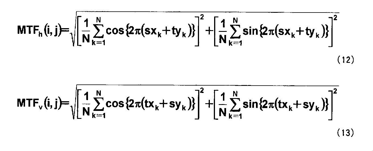
- Equation (12) Equation (12) and Equation (13), respectively, and can be calculated from the spot diagram.
- Prediction mode candidate limited process Details of the prediction mode candidate limiting step in step S3 in the intra prediction processing procedure of FIG. 1 described above will be described.
- the prediction mode candidates of the processing target block are limited according to the direction component of the resolution information (MTF) obtained in step S2 from a plurality of predetermined prediction mode candidates.
- MTF direction component of the resolution information
- This step in the present embodiment is for narrowing down prediction mode candidates using resolution information and reducing the amount of calculation processing of intra prediction processing in steps S4 to S6. Since the resolution information of the input image is used, there is no need to perform image analysis in advance or generate a pattern assuming the input image.
- the outline of the prediction mode candidate limiting step in the present embodiment will be described with reference to FIG. 10, taking an example of using an optical system (lens) for imaging.
- the resolving power varies depending on the distance from the center position of the lens.
- the resolution distribution is a parameter that varies depending on the lens.
- the prediction mode evaluation process can be greatly reduced.
- the resolving power of such a lens is information that varies depending on the distance (image height) from the center of the lens and the direction at that position. For this reason, each lens determines the resolving power in consideration of the position in the image and the direction of the prediction mode, and selects the prediction mode candidates in light of the directionality, thereby reducing the optimal amount of calculation processing. Do.
- FIG. 11 is a diagram for illustrating the position of the processing target block 4 in the target image 3.
- the center of the image is (C X , C Y )
- the angle ⁇ formed by the image center and the target pixel, and the distance (image height) 1 between the image center and the target pixel are expressed as follows. .
- the direction d X is a direction representing M X.
- s and t shown in the figure represent the S (Sagittal) direction and the T (Tangential) direction
- the MTF at the point (i, j) is a function of the image height l in the S direction and the T direction, respectively. Defined as S (l) and T (l).
- MTF (d X ) ⁇ H 2-5
- the prediction mode M 1 is deleted from the prediction mode candidates.
- the prediction mode M 4 is deleted from the prediction mode candidates.
- the threshold value H is determined by the pixel pitch of the image sensor and the frequency of the MTF data.
- the number of prediction modes can be reduced based on the point image reproducibility of the lens, so that the amount of calculation processing can be reduced without causing deterioration in image quality.
- the prediction mode of the block can be determined as M 2. The amount of calculation processing can be greatly reduced.
- the present invention can also be applied to other intra prediction modes such as the intra 16 ⁇ 16 prediction mode.
- resolution directionality depending on the position in the image such as image distortion caused by the image processing, may be used.
- FIG. 16 There is a conventional technique for correcting an image photographed with a wide-angle lens or a lens that generates distortion using image processing. For example, as shown in FIG. 16, this is a technique for correcting a distorted image.
- a distorted image before image processing and (b) a corrected image after image processing are represented as a grid-like image.
- this resolution information can be handled in the same manner as the above-described MTF, it can be used to select a prediction mode candidate and can be prioritized.
- the second embodiment may dynamically fluctuate unlike static data. For example, in an in-vehicle camera viewpoint conversion application, image processing is performed as time passes.
- FIG. 17 shows an example of an encoder incorporating this image processing in its configuration.
- image processing 8 is first performed on the input signal acquired from the imaging device.
- the image processing 8 includes various processing such as processing for viewpoint conversion, zoom processing, pan processing, color correction processing, and the like.
- the resolution is similarly calculated, and the intra prediction is performed according to the characteristics of the image processed in the image processing 8. Processing can be performed.
- the present invention that can assign priorities to a plurality of prediction mode candidates can be applied both statically and dynamically.
- the present invention relates to the H.264 standard.
- the present invention can be applied not only to H.264 intra prediction processing but also to general intra prediction processing for predicting a processing target block from adjacent blocks. Prediction using a weighted average or prediction processing involving some conversion can also be applied.
- a prediction mode candidate holding step is provided during or before or after the prediction mode determination step of steps S4 to S6 after the prediction mode candidate limiting step of step S3 ends. May be.
- the prediction mode candidate holding step the result of the prediction mode candidate limiting step relating to the input image imaging system, that is, a prediction mode candidate table in which the processing target block position is associated with the limited prediction mode candidate is held.
- step S2 for input images of the same imaging system, a step of setting prediction mode candidates based on the information of the prediction mode candidate table held as described above is provided, so that step S2 and step of FIG.
- the step of S3 can be omitted.
- the resolution information used for limiting the prediction mode candidates does not depend on the input image, it can be applied as it is when the prediction mode candidate limitation results obtained once are the same system.
- the intra-prediction processing method and the intra-prediction processing program when predictive encoding processing of an input image, a plurality of information are obtained based on resolution information at the position of the processing target block in the input image.
- the prediction mode candidates are narrowed down to the limited prediction mode candidates, and the prediction block corresponding to the processing target block is predicted from the adjacent block.
Landscapes
- Engineering & Computer Science (AREA)
- Multimedia (AREA)
- Signal Processing (AREA)
- Compression Or Coding Systems Of Tv Signals (AREA)
Abstract
本発明に係るイントラ予測処理方法は、入力画像の複数画素で構成される符号化の処理対象ブロックを設定する処理ブロック設定工程と、前記処理対象ブロックを何れの方向の近接ブロックから、どの様に補間して予測画像を作るかを表す補間パターンである所定数の予測モードの候補を、前記処理対象ブロックの解像度情報に基づき、前記所定数より少ない複数の予測モードの候補に絞り込む予測モード候補限定工程と、前記予測モード候補限定工程において限定された前記予測モード候補の中から、予測符号化のコストが最小となる予測モードを予測符号化に用いる予測モードとして決定し、予測符号化処理に用いる予測モード決定工程と、前記予測モード決定工程で決定された予測モードにて、前記処理対象ブロックの予測画像を作成した後に、前記予測画像を用いて前記処理対象ブロックを符号化する予測符号化工程と、を備えたことを特徴とする。
Description
本発明は、入力画像の予測符号化に用いるため、複数画素からなる処理対象ブロックについて、対応する予測ブロックを、予測モードに従って隣接ブロックから予測するイントラ予測処理方法、及びイントラ予測処理プログラムに関する。
動画圧縮処理等において、同じフレーム内で予測を行うイントラ予測処理による符号化や、時間的に連続するフレーム間で予測を行うインター予測符号化などの予測符号化技術が知られている。
これらは、画像符号化方式の国際標準・規格にも採用されており、例えば、H.264/MPEG-4 AVC(以降、H.264と呼称する)方式のエンコーダは、図2に示すように構成されている。
図2のH.264エンコーダ1のイントラ予測処理部2において、隣接ブロックから予測パターンを決定するイントラ予測処理が実行される。
イントラ予測処理方法は、入力画像において、複数画素からなる処理対象ブロックを設定し、対応する予測ブロックを隣接ブロックから予測するものであり、この予測に基づき予測符号化処理を行う。
予測ブロックが処理対象ブロックに近ければ近いほど、予測符号化のコストは小さくなる。すなわち、情報量としてより圧縮することができる。処理対象ブロックの画像は隣接するブロックの画像に近いと推定し、隣接ブロックから予測するのである。
詳細は後述するが、どの隣接ブロックの画素からどのように予測するかによって、複数の予測モードが設定されている(図4に具体例を示す)。
複数の予測モードは主にどの方向の隣接ブロックがより近いかを示すものであるが、どの予測モード(予測方向)を用いると予測精度がよくなるかは予め分からない。
従って、すべての予測モードを実行してみて、最も予測精度のよい、すなわち符号化コストの最小となる予測モードを探索することが一般的に行われている。
しかしながら、すべての予測モードを実行し、さらに符号化コストを算出し評価する段階まで処理を進めなければならないため、その演算量は膨大となる。
このようにイントラ予測処理方法は、非常に計算量の多い処理として知られており、そのため、イントラ予測処理方法における予測モード決定のための計算量の削減が重要な技術課題として研究されてきた。
例えば、特許文献1では、イントラ予測処理によって符号化済みの隣接ブロックの予測モードを参考にして、予測モードを絞り込む手法が提案されている。
図4を参照して具体例を示すと、対象ブロックの上の隣接ブロックがモードM1、左の隣接ブロックがモードM5の場合には、M1、M5に加えて、それらの間の角度となるM4、M6(図4右下参照)との4つの予測モードを候補として限定している。
また、特許文献2では、対象ブロックの空間的な位置、あるいは時間軸上の位置に応じて、予測モード候補数を限定し、予測モードを評価する演算量を削減している。
特許文献2によれば、画像内のあるブロックにおいて、予測モードの候補数を限定するブロックを外部入力により決定している。限定するモード数も外部入力として与えられ、ブロックごとに可変である。
このようにして、各ブロックにおいて決定された予測モードの候補数に基づき、優先順位が付けられた符号化済み近隣ブロックの予測モードから候補の予測モードを決定している。
上に述べてきたように、予測符号化のためのイントラ予測処理は計算量が非常に多く、その処理を削減する方法が提案されてきた。
特に予測モード候補の数を絞り込むことで計算量を抑制しようと、上記特許文献1や特許文献2に記載されたような技術が研究されてきた。
しかしながら、絞り込んだ予測モード候補による予測の精度という点から考慮すると、例えば特許文献1や2に記載の従来の方法では、以下のような問題がある。
第1に、予測モード候補を限定するために参照する符号化済み近隣ブロックの予測モード自体も、上述したように限定して決定した予測モードである。そのため、本当に最適な予測モードに決定できたかどうかは分からない。
第2に、符号化済みの近隣ブロックしか参考にできない。そのため、未処理領域に似たような予測モードの傾向を示す領域が存在し、符号化処理済み領域には存在しない場合には、符号化処理済み領域の予測モードを用いて予測モードを限定することが最適とは言えない。
第3に、イントラ予測処理を行うブロックの度に符号化済み近隣ブロックの予測モードを参照するようなこれらの手法は、リアルタイムでの処理に不向きである。例えば、超広角系のように常に一定の特徴が含まれる場合には、イントラ予測処理ブロックごとに近隣ブロックを参照する処理は冗長になってしまう。
すなわち、上記のような従来手法では、予測モード候補の限定方法が、符号化処理済み領域での処理内容に依存したり、処理する入力画像に固有の特徴に依存したりして、簡単迅速に最適な予測モード候補に絞り込めるものとは言えなかった。
本発明は、上記の技術的課題に鑑みてなされたものである。
本発明の目的は、入力画像の予測符号化処理に際して、符号化処理済み領域の予測モードや処理対象画像に固有の特徴等に依存せずに、簡単迅速に最適な予測モード候補に絞り込み、予測モード決定のための計算量を削減することができるイントラ予測処理方法、及びイントラ予測処理プログラムを提供することである。
上記の課題を解決するために、本発明は以下の特徴を有するものである。
第1の態様に係るイントラ予測処理方法は、入力画像の複数画素で構成される符号化の処理対処ブロックを設定する処理ブロック設定工程と、前記処理対象ブロックを何れの方向の近接ブロックから、どの様に補間して予測画像を作るかを表す補間パターンである所定数の予測モードの候補を、前記処理対象ブロックの解像度情報に基づき、前記所定数より少ない複数の予測モード候補に絞り込む予測モード候補限定工程と、前記予測モード候補限定工程において限定された前記予測モード候補の中から、予測符号化のコストが最小となる予測モードを予想符号化に用いる予測モードとして決定し、予測符号化処理に用いる予測モード決定工程と、前記予測モード決定工程で決定された予測モードにて、前記処理対象ブロックの予測画像を作成した後に、前記予測画像を用いて前記処理対象ブロックを符号化する予測符号化工程と、を備えたことを特徴とするイントラ予測処理方法。
第2の態様に係るイントラ予測処理方法は、前記予測モード候補限定工程においては、前記複数の所定の予測モード候補について、それぞれの予測モード候補の示す方向と対応する前記解像度情報の方向成分に基づき、当該予測モード候補の優先度を判定することにより、限定された予測モード候補に絞り込むことを特徴とする第1の態様に係るイントラ予測処理方法。
第3の態様に係るイントラ予測処理方法は、前記予測モード候補限定工程においては、前記入力画像を撮像した撮像装置の光学特性を、前記解像度情報として用いることを特徴とする第1または第2の態様に係るイントラ予測処理方法。
第4の態様に係るイントラ予測処理方法は、前記撮像装置の光学特性は、MTFであることを特徴とする第3の態様に係るイントラ予測処理方法。
第5の態様に係るイントラ予測処理方法は、前記予測モード候補限定工程においては、前記入力画像の前処理における画像処理内容により決定される前記解像度情報を用いることを特徴とする第1または第2の態様に係るイントラ予測処理方法。
第6の態様に係るイントラ予測処理方法は、前記入力画像の撮像システムに関して、処理対象ブロック位置と前記予測モード候補限定工程において限定された前記予測モード候補とを対応づけた予測モード候補テーブルを保持する予測モード候補保持工程を有し、前記予測モード決定工程においては、同じ撮像システムについて保持されている前記予測モード候補テーブルの情報に基づいて前記限定された予測モード候補を設定することを特徴とする第1から第3の何れか1項の態様に係るイントラ予測処理方法。
第7の態様に係るイントラ予測処理プログラムは、コンピュータに、入力画像の複数画素で構成される符号化の処理対処ブロックを設定する処理ブロック設定工程と、前記処理対象ブロックを何れの方向の近接ブロックから、どの様に補間して予測画像を作るかを表す補間パターンである所定数の予測モードの候補を、前記処理対象ブロックの解像度情報に基づき、前記所定数より少ない複数の予測モード候補に絞り込む予測モード候補限定工程と、前記予測モード候補限定工程において限定された前記予測モード候補の中から、予測符号化のコストが最小となる予測モードを予想符号化に用いる予測モードとして決定し、予測符号化処理に用いる予測モード決定工程と、前記予測モード決定工程で決定された予測モードにて、前記処理対象ブロックの予測画像を作成した後に、前記予測画像を用いて前記処理対象ブロックを符号化する予測符号化工程と、を備えたことを特徴とするイントラ予測処理プログラム。
第8の態様に係るイントラ予測処理プログラムは、前記予測モード候補限定工程においては、前記複数の所定の予測モード候補について、それぞれの予測モード候補の示す方向と対応する前記解像度情報の方向成分に基づき、当該予測モード候補の優先度を判定することにより、限定された予測モード候補に絞り込むことを特徴とする第7の態様に係るイントラ予測処理プログラム。
第9の態様に係るイントラ予測処理プログラムは、前記予測モード候補限定工程においては、前記入力画像を撮像した撮像装置の光学特性を、前記解像度情報として用いることを特徴とする第7または第8の態様に係るイントラ予測処理プログラム。
第10の態様に係るイントラ予測処理プログラムは、前記撮像装置の光学特性は、MTFであることを特徴とする第9の態様に係るイントラ予測処理プログラム。
第11の態様に係るイントラ予測処理プログラムは、前記予測モード候補限定工程においては、前記入力画像の前処理における画像処理内容により決定される前記解像度情報を用いることを特徴とする第7または第8の態様に係るイントラ予測処理プログラム。
第12の態様に係るイントラ予測処理プログラムは、前記コンピュータに、前記入力画像の撮像システムに関して、処理対象ブロック位置と前記予測モード候補限定工程において限定された前記予測モード候補とを対応づけた予測モード候補テーブルを保持する予測モード候補保持工程を実行させ、前記予測モード決定工程においては、同じ撮像システムについて保持されている前記予測モード候補テーブルの情報に基づいて前記限定された予測モード候補を設定することを特徴とする第7から第10の何れか1項の態様に係るイントラ予測処理プログラム。
本発明に係るイントラ予測処理方法、及びイントラ予測処理プログラムによれば、入力画像の予測符号化処理に際して、入力画像における処理対象ブロックの位置での解像度情報に基づき、複数の所定の予測モード候補から限定された予測モード候補に絞り込み、処理対象ブロックに対応する予測ブロックを、隣接ブロックから予測する。
これにより、符号化処理済み領域の予測モードや処理対象画像に固有の特徴等に依存せずに、簡単迅速に最適な予測モード候補に絞り込み、予測モード決定のための計算量を削減することができる。
(第1の実施形態)
本発明に係るイントラ予測処理方法、及びイントラ予測処理プログラムの一実施形態を、以下に図を用いて説明する。
本発明に係るイントラ予測処理方法、及びイントラ予測処理プログラムの一実施形態を、以下に図を用いて説明する。
(イントラ予測処理の手順例)
図1は、本実施形態に係るイントラ予測処理方法の概略処理手順例を示すフローチャートである。図1を用いて、本実施形態に係るイントラ予測処理方法の概略処理手順例を説明する。
図1は、本実施形態に係るイントラ予測処理方法の概略処理手順例を示すフローチャートである。図1を用いて、本実施形態に係るイントラ予測処理方法の概略処理手順例を説明する。
なお、以下に述べるイントラ予測処理方法の処理手順は、それらを実行するようにプログラムされたイントラ予測処理プログラムをコンピュータ等の情報処理装置に適用することにより実行される。
図1において、ステップS1は、入力画像のイントラ予測による予測符号化処理実行の対象となるブロックとして、対象画像に複数画素からなる処理対象ブロックを設定する。
ステップS2は、入力画像における、設定した処理対象ブロックの位置での解像度情報(例えばMTF)の方向成分を算出する、あるいは取得する。MTFは、Moduler Transfer Functionであり、詳細は後述する。
ステップS3は、予測モード候補限定工程であり、複数の所定の予測モード候補から、ステップS2で求められた解像度情報(以降、MTFとする)の方向成分に応じて、処理対象ブロックの予測モード候補を限定する。
なお予測モードとは、処理対象のブロックを隣接ブロックから予測するためのパターンを示すものであり、パターンの方向性の異なる複数のモードが候補として設定されている。詳細は後述する。
予測モード候補の限定数は、1つであっても複数であってもよい。本実施形態では、複数の候補に限定されたとして説明する。
ステップS3の解像度情報に基づく予測モード候補限定工程の詳細については、具体例を後述して、説明する。
ステップS4からステップS6は、予測モード決定工程であり、ステップS3で限定された予測モード候補について、予測符号化のコストが最小となる予測モード候補を予測モードとして決定する。
またそのために、ステップS4からステップS6では、それぞれの予測モード候補での予測符号化のコスト評価を行っている。
ステップS4は、設定した処理対象ブロックに対して、ステップS3で限定された予測モード候補ごとに、当該予測モードに従い隣接ブロックを参照し、予測ブロックを算出する。
ステップS5は、限定された予測モード候補ごとに算出された予測ブロックを用いて、処理対象ブロックのコスト計算処理を行う。予測モード候補ごとの予測符号化のコスト評価を比較するためである。
ステップS6は、ステップS5の予測符号化のコスト評価結果により、設定した処理対象ブロックに対する予測モードを1つに決定する。すなわち、予測モード候補のうち、符号化コストが最小となる予測モード候補を予測モードとして決定する。
ステップS4からステップS6の予測モード決定工程の詳細については、具体例を後述して、説明する。
ステップS7は、予測符号化工程であり、設定した処理対象ブロックについて、ステップS6で決定された予測モードでの予測符号化処理を行う。
なお、決定された予測モードでの予測符号化は、ステップS5で、コスト評価の際に予測符号化処理まで実行しておき、その処理結果を参照するようにしてもよい。
ステップS8は、処理対象の画像に対して、すべての処理対象ブロックを設定し、上記手順によるイントラ予測処理を終えたかどうかを判定する。
ステップS8で判定がYesの場合は、対象画像に対するイントラ予測処理は終了する。
ステップS8で判定がNoの場合は、ステップS1へ戻り、次の処理対象ブロックを設定し、ステップS8までを繰り返す。
ステップS1からステップS8の反復は、ステップS8で判定がYesとなり、対象画像に対するイントラ予測処理が終了するまで継続する。
本実施形態に係るイントラ予測処理方法とそれを実行するためのイントラ予測処理プログラムでは、このようにして予測モード決定工程の前に、符号化処理済み領域の予測モードや処理対象画像に固有の特徴等に依存しない解像度情報に基づく予測モード候補限定工程を実行する。
これにより、予測モードを決定するための符号化コスト評価の計算量を削減し、簡単迅速に最適な予測モード候補に絞り込めるよう図っている。
以下にまず、イントラ予測処理の従来技術としての予測モード決定工程について詳細を述べ、その後で光学特性としてのMTFとその方向成分の算出について述べ、その解像度と方向成分に基づいた予測モード候補限定工程の処理例を説明する。
(予測モード決定工程)
上述したステップS4からステップS6の予測モード決定工程について詳細を説明する。
上述したステップS4からステップS6の予測モード決定工程について詳細を説明する。
予測モード決定工程では、イントラ予測処理において設定されている複数の予測モード候補から、予測符号化に用いる予測モードを決定する処理が行われる。この工程は、従来の公知技術(画像符号化方式の国際標準・H.264/MPEG-4 AVC)を用いる例を説明する。
イントラ予測処理は、従来の画像符号化装置においても適用されている予測符号化方法であり、フレーム内で予測を行う予測符号化処理である。
入力画像において、複数画素からなる処理対象ブロックを設定し、対応する予測ブロックを隣接ブロックから予測するものであり、この予測に基づき予測符号化処理を行う。
例えば、H.264/MPEG-4 AVC方式のエンコーダの構成を、既に図2に示した。図2のH.264エンコーダ1のイントラ予測処理部2において、隣接ブロックから予測パターンを決定するイントラ予測処理が実行される。
図3は、イントラ予測処理について説明するための対象画像例を示した説明図である。イントラ予測処理部2で行われるイントラ予測処理について、図3を用いて説明する。
動画像(入力画像)から1枚のフレーム(対象画像)3を抽出したとき、通常は画像内の被写体はある程度の領域で分布しており、隣り合う画素において画素値(輝度や色)が類似していることが多い。このことを利用して、近傍にある隣接ブロック5の画素から、符号化の処理対象ブロック4の画素値の推定を行うのがイントラ予測処理である。
H.264では、符号化の処理対象ブロック4に対して、符号化済み領域6に含まれる上、左、右上、左上のブロックが隣接ブロック5として定義されている。
次に、具体的なイントラ予測処理について述べる。
<予測モードについて>
どの隣接ブロックからどのように予測するかについては、複数の予測モードがパターンとして設定されている。
どの隣接ブロックからどのように予測するかについては、複数の予測モードがパターンとして設定されている。
H.264では、輝度信号を用いる
・イントラ4×4(画素)予測モード
・イントラ16×16(画素)予測モード
と、色差信号を用いる
・イントラ8×8(画素)予測モード
と、が定義されている。
・イントラ4×4(画素)予測モード
・イントラ16×16(画素)予測モード
と、色差信号を用いる
・イントラ8×8(画素)予測モード
と、が定義されている。
それぞれの予測モードには、平均値と画素の予測方向とを表すモードと呼ばれる番号が定義されている。
例えば、図4に輝度信号のイントラ4×4予測モードのパターン図を示す。イントラ4×4予測モードでは、図4に示すように、平均値を表すMode2(以降はModeX=MXと表記する)と、方向を表すM0、M1、M3、M4、・・・、M8との9種類の予測モードが定義されている。
さらに輝度信号においては、画素単位を16×16画素サイズにしたイントラ16×16予測モードが図5のように4種類の予測モードで定義されている。図5に輝度信号のイントラ16×16予測モードのパターン図を示す。
同様にして、色差信号においても8×8画素のイントラ8×8予測モードが図6のように定義されている。図6に色差信号のイントラ8×8予測モードのパターン図を示す。
これらの予測モード番号と、そのモードで実際に予測した結果からの差分値とを符号化することで、画像そのものを符号化するよりも遥かに高い圧縮率を実現している。
図4のアルファベット記号を用いてより具体的に示す。
例えばイントラ4×4予測モードのM0のとき、隣接画素A~Dが符号化済みであれば、符号化の処理対象ブロックa~pは、
a,e,i,m=A (1)
b,f,j,n=B (2)
c,g,k,o=C (3)
d,h,l,p=D (4)
と予測され、イントラ4×4予測モードのM1の場合、隣接画素I~Lが符号化済みであれば、
a,b,c,d=I (5)
e,f,g,h=J (6)
i,j,k,l=K (7)
m,n,o,p=L (8)
と予測される。イントラ4×4予測モードのM2の場合は、
a~p=(A+B+C+D+I+J+K+L+4)>>3
(A~D,I~Lが符号化済みのとき)
a~p=(I+J+K+L+2)>>2
(A~Dのどれかが参照不可で、I~Lがすべて符号化済みのとき)
a~p=(A+B+C+D+2)>>2
(A~Dがすべて符号化済みで、I~Lのどれかが参照不可のとき)
a~p=128
(A~DとI~Lとに参照不可が含まれるとき)
(9)
と予測される。同様にしてM3、M4、・・・、M8も図4で示されている方向に従って予測される。
a,e,i,m=A (1)
b,f,j,n=B (2)
c,g,k,o=C (3)
d,h,l,p=D (4)
と予測され、イントラ4×4予測モードのM1の場合、隣接画素I~Lが符号化済みであれば、
a,b,c,d=I (5)
e,f,g,h=J (6)
i,j,k,l=K (7)
m,n,o,p=L (8)
と予測される。イントラ4×4予測モードのM2の場合は、
a~p=(A+B+C+D+I+J+K+L+4)>>3
(A~D,I~Lが符号化済みのとき)
a~p=(I+J+K+L+2)>>2
(A~Dのどれかが参照不可で、I~Lがすべて符号化済みのとき)
a~p=(A+B+C+D+2)>>2
(A~Dがすべて符号化済みで、I~Lのどれかが参照不可のとき)
a~p=128
(A~DとI~Lとに参照不可が含まれるとき)
(9)
と予測される。同様にしてM3、M4、・・・、M8も図4で示されている方向に従って予測される。
<予測モードの決定と計算量>
H.264のイントラ予測処理は画素単位での予測を行うため、きめ細かい予測が可能となり、高画質で高圧縮な符号化を実現している。しかしながら、その一方で予測に要する演算処理量は激増している。
H.264のイントラ予測処理は画素単位での予測を行うため、きめ細かい予測が可能となり、高画質で高圧縮な符号化を実現している。しかしながら、その一方で予測に要する演算処理量は激増している。
例えば、16×16画素の輝度信号マクロブロックの予測モードを決定する処理の例を、図7を用いて説明する。図7は、イントラ予測処理における予測モード決定手順の一例を示すフローチャートである。
図7の重要なステップのみ以下に述べる。
ステップS11:イントラ16×16予測モードで予測を行う。予測モードは4種類(図5参照)あるため、符号化コスト算出処理を4回繰り返し、コストが最小となるMαiを決定する。
ステップS12:マクロブロック内にエッジが含まれるかどうかを判定する。エッジが含まれていなければ、当該マクロブロックの予測モードはイントラ16×16予測モードのMαiとして決定する。
ステップS13:マクロブロック内にエッジが含まれている場合は、4×4画素単位のサブマクロブロック16個に分割し、各々のマクロブロックで9種類(図4参照)のイントラ4×4予測モードを検討する。つまり符号化コスト算出処理を最大9×16回繰り返す。
ステップS14:あるサブマクロブロックにおけるイントラ4×4予測モードが決まる度に、当該マクロブロックにおける現時点での累積符号化コスト(ΣCost(Mβbj))(Σはb=0~15)と、ステップS11で得られたMαiの符号化コストとを比較する。
Mαiの符号化コストの方が小さければサブマクロブロックでの計算を中止し、Mαiを当該マクロブロックの予測モードとして決定する。サブマクロブロックの累積符号化コストの方が小さければ、当該マクロブロックで16個の予測モードMβbj(0≦b≦15)を決定する。
以上のように、各ブロックですべての予測方向(予測モード)に対して符号化コストを評価する必要がある。符号化コストを評価するためには、その予測モードで符号化した場合にどれだけの符号量になるのかを判断するため、イントラ予測処理の次のステップまで処理を進める必要があり、その演算量は膨大になる。
そこで、この演算処理量を削減するために、従来から様々な手法が提案されている(例えば、特許文献2、3参照)。
これらは、既に述べたように、予測モード候補を限定して絞り込むことで、演算量を削減しようとするものであるが、予測モード候補の限定方法が、符号化処理済み領域での処理内容に依存したり、処理する入力画像に固有の特徴に依存したりして、簡単迅速に最適な予測モード候補に絞り込めるものとは言えない。
本実施形態は、予測モード決定工程に先立ち、予測モード候補限定工程を設け、その中で、入力画像における処理対象ブロックの位置での解像度情報に基づき、複数の所定の予測モード候補から限定された予測モード候補に絞り込む処理を行っている。
これにより、撮像時の光学特性(MTF)等、入力画像に依存しない、すなわち符号化処理済み領域の予測モードや処理対象画像に固有の特徴等に依存しない解像度情報に基づくことで、簡単迅速に最適な予測モード候補に絞り込み、予測モードを決定するための符号化コスト評価の計算量を削減している。
また入力画像に依存しない解像度情報に基づくため、限定された予測モード候補をテーブルにして保持しておけば、絞り込みのための評価も、その都度演算する必要がなくなり、リアルタイムでの予測符号化処理も可能となる。
以下に、まず光学特性による解像度(方向成分)の低下について述べる。MTFを例に採っているが、光学特性(解像度情報)としては、OTF、PSFなど、他の特性を用いてもよい。
<MTF>
カメラなどの撮像装置における光学系の性能を表す指標の1つにMTF(Moduler Transfer Function)がある。
カメラなどの撮像装置における光学系の性能を表す指標の1つにMTF(Moduler Transfer Function)がある。
MTFは、被写体の持つコントラストをどの程度忠実に再現できるかを空間周波数特性として表現したものである。空間周波数は、1[mm]当たりに含まれるパターン(正弦波など)数を示す。
MTFは一般的に、周波数を固定(60本/mm、100本/mmなど)して、横軸に画像中心からの距離(像高)をとったグラフにおいて、画像中心から放射状の方向(Sagittal)と同心円方向(Tangential)の2方向についてプロットしたものとして表現される。
図8は、MTFと像高の関係の代表的な例を示すグラフである。
一般に、MTFは像高が高くなるに従って低下する傾向があり、また、放射状の方向(Sagittal)と同心円方向(Tangential)で異なる値をとることがある。その差異は、広角な光学系においては、顕著に現れる。
また、MTFを計測する方法として、特許文献(特開2001-324413号公報)のような方法が開示されている。
<画像処理>
一方、撮像された画像をイントラ予測処理の前に画像処理する場合がある。そのような場合には、画像処理の結果としての解像度情報を用いてもよい。
一方、撮像された画像をイントラ予測処理の前に画像処理する場合がある。そのような場合には、画像処理の結果としての解像度情報を用いてもよい。
例えば、特許文献(特開2009-284421号公報)では、広角な車載カメラで撮影した画像を歪み補正及び視点変換した画像を表示している。
このような画像では、元の撮像系で撮影された画像に対して画像処理による拡大・縮小処理が行われており、特に拡大処理が行われている部分では解像度が低下している。
生成される画像解像度は、同じ画像処理を適用している間は、画面のそれぞれの領域で一定である。
(MTFの方向成分の算出)
ここでは、画像の解像度特性として撮像系のMTFを用いる場合を説明する。MTFの方向成分に応じて予測モード候補を取捨選択するために、まず光学系の設計データから水平・垂直方向のMTF成分を算出する方法について述べる。
ここでは、画像の解像度特性として撮像系のMTFを用いる場合を説明する。MTFの方向成分に応じて予測モード候補を取捨選択するために、まず光学系の設計データから水平・垂直方向のMTF成分を算出する方法について述べる。
<光学系の設計データからの算出>
画像上の各座標における垂直及び水平方向のMTFは、光学系の設計データを用いてシミュレーションによって求めることができる。
画像上の各座標における垂直及び水平方向のMTFは、光学系の設計データを用いてシミュレーションによって求めることができる。
画像上の任意の点におけるスポットダイヤグラム(点光源から瞳面上のN個の格子点を通る光線が画像上に作る点群。光線追跡によって求められる)のN個の点の座標をxk、ykとする。Sagittal方向と画像の水平面のなす角をαとし、その方向の周波数をw本/mmとすると、Sagittal方向の周波数sとTangential方向の周波数tは、図9からそれぞれ式(10)及び式(11)のようになる。
s=wcosα (10)
t=wsinα (11)
MTFの水平及び垂直方向の値、MTFh(i,j)及びMTFv(i,j)は、それぞれ式(12)及び式(13)のように表すことができ、スポットダイヤグラムから計算できる。
t=wsinα (11)
MTFの水平及び垂直方向の値、MTFh(i,j)及びMTFv(i,j)は、それぞれ式(12)及び式(13)のように表すことができ、スポットダイヤグラムから計算できる。
<像高に対するMTF値からの算出>
MTFの水平及び垂直方向成分の値が算出されれば、説明は略すが、任意の方向の成分を求めることができる。
MTFの水平及び垂直方向成分の値が算出されれば、説明は略すが、任意の方向の成分を求めることができる。
<像高に対するMTF値からの算出>
図8のようなSagittal方向及びTangential方向のMTF値のみが得られるときの、MTFの任意の方向の成分を求める求め方については後で述べる。
図8のようなSagittal方向及びTangential方向のMTF値のみが得られるときの、MTFの任意の方向の成分を求める求め方については後で述べる。
(予測モード候補限定工程)
既述した図1のイントラ予測処理手順における、ステップS3の予測モード候補限定工程について詳細を説明する。
既述した図1のイントラ予測処理手順における、ステップS3の予測モード候補限定工程について詳細を説明する。
<解像度情報の方向成分による予測モード候補の限定>
予測モード候補限定工程では、複数の所定の予測モード候補から、ステップS2で求められた解像度情報(MTF)の方向成分に応じて、処理対象ブロックの予測モード候補を限定する。
予測モード候補限定工程では、複数の所定の予測モード候補から、ステップS2で求められた解像度情報(MTF)の方向成分に応じて、処理対象ブロックの予測モード候補を限定する。
本実施形態におけるこの工程は、解像度情報を利用して予測モード候補を絞り込み、ステップS4からステップS6の工程でのイントラ予測処理の演算処理量を削減するためのものである。入力画像の解像度情報を利用するため、事前に画像解析を行ったり、入力画像を想定したパターンを生成したりする必要はない。
本実施形態における予測モード候補限定工程の概要を、撮像に光学系(レンズ)を用いた形態を例にとって、図10を用いて説明する。
撮像対象の物体を光学系としてレンズを介して結像させると、レンズの中心位置からの距離によってその解像力が異なる。また、その解像力の分布は、レンズによって異なるパラメータである。
この解像力情報を利用して、画質の劣化を招かないように演算処理量の削減を行う。
図10に示すように、レンズの解像力が高ければ(図10上)一画素ずつ処理を行い、高画質、高圧縮を狙った予測を行う。
一方で、レンズの解像力がそもそも低いのであれば(図10下)、演算コストが高い一画素単位の処理を行う必要はない。方向を表す予測モードは考慮せずに、演算コストが低い予測モード候補、例えばM2(図4参照)と限定すれば、予測モードの評価処理を大幅に削減することができる。
ところで、このようなレンズの解像力は、レンズの中心からの距離(像高)、またその位置での方向によっても異なる情報である。このため、各レンズによって、画像中の位置と、予測モードの方向とを加味して解像力を判断し、予測モード候補をその方向性と照らして取捨選択することにより、最適な演算処理量削減を行う。
例えば、設定した処理対象ブロックの位置において、複数の所定の予測モード候補について、それぞれの予測モード候補の方向性と対応する解像度情報の方向成分に基づき、当該予測モード候補を取捨選択することにより、限定された予測モード候補に絞り込む。
解像度の方向成分に応じて予測モード候補を限定する具体的な処理について、以下に説明する。
<像高に対するMTF値からの方向成分算出>
図11は、対象画像3における処理対象ブロック4の位置を示すための図である。
図11は、対象画像3における処理対象ブロック4の位置を示すための図である。
図11に示す画素f(i,j)を左上にした4×4画素の処理対象ブロック4のイントラ予測処理を行うとする。
このとき、画像の中心を(CX,CY)とすれば、画像中心と対象画素とがなす角度θ、画像中心と対象画素との距離(像高)lは、それぞれ以下で表される。
θ=arctan(|j-CY|/|i-CX|) (14)
l=|(i,j)-(CX,CY)| (15)
さらに、画素f(i,j)を左上にしたブロックを処理対象ブロック4とすると、点(i,j)におけるイントラ4×4予測モードの方向性を図12のように表す。
l=|(i,j)-(CX,CY)| (15)
さらに、画素f(i,j)を左上にしたブロックを処理対象ブロック4とすると、点(i,j)におけるイントラ4×4予測モードの方向性を図12のように表す。
ここで方向dXは、MXを表す方向であるとする。また、図に示しているs、tはS(Sagittal)方向、T(Tangential)方向を表しており、点(i,j)におけるMTFを、像高lの関数としてS方向、T方向でそれぞれS(l)、T(l)として定義する。
これらを用いて、点(i,j)におけるdX(X={0,1,3,4,・・・,8})方向のMTFを以下のように定義する。
MTF(dX)=|S(l)cosδ|+|T(l)sinδ| (16)
ここで、δは以下の通りである。
ここで、δは以下の通りである。
δ=|θ-(1/2)π| (d0のとき) (17)
δ= θ (d1のとき) (18)
δ=|θ-(3/4)π| (d3のとき) (19)
δ=|θ-(1/4)π| (d4のとき) (20)
δ=|θ-(3/8)π| (d5のとき) (21)
δ=|θ-(1/8)π| (d6のとき) (22)
δ=|θ-(5/8)π| (d7のとき) (23)
δ=|θ+(1/8)π| (d8のとき) (24)
例えば、d0方向のMTFは、図13のように捉えることができる。また同様に、d1、d5方向についても図14、15のように表すことができる。
δ= θ (d1のとき) (18)
δ=|θ-(3/4)π| (d3のとき) (19)
δ=|θ-(1/4)π| (d4のとき) (20)
δ=|θ-(3/8)π| (d5のとき) (21)
δ=|θ-(1/8)π| (d6のとき) (22)
δ=|θ-(5/8)π| (d7のとき) (23)
δ=|θ+(1/8)π| (d8のとき) (24)
例えば、d0方向のMTFは、図13のように捉えることができる。また同様に、d1、d5方向についても図14、15のように表すことができる。
<予測モード候補の限定>
上記のようにして求めた解像度(MTF)のdX方向成分に応じて、対応する方向性を有する予測モード候補を選別する処理例を説明する。
上記のようにして求めた解像度(MTF)のdX方向成分に応じて、対応する方向性を有する予測モード候補を選別する処理例を説明する。
例えば、求めたdX(X={0,1,3,4,・・・,8})方向のMTFを、所定の閾値Hと比較して、
MTF(dX)<H (25)
となるとき、dX方向に対応する(例えば垂直な)方向性を有する予測モードMYは、予測モードの候補から削除するものとする。
MTF(dX)<H (25)
となるとき、dX方向に対応する(例えば垂直な)方向性を有する予測モードMYは、予測モードの候補から削除するものとする。
例えば、d0方向のMTFが閾値Hを下回るときは、予測モードM1は予測モードの候補から削除する。d3方向のMTFが閾値Hを下回るときは、予測モードM4は、予測モードの候補から削除する。
ここで閾値Hは、撮像素子の画素ピッチ、及びMTFデータの周波数により決定する。
本実施形態の予測モード候補限定方法によれば、レンズの点像再現性に基づいて予測モードの候補を減らすことができるため、画質の劣化を招くことなく、演算処理量を削減することができる。
もし、MTF(dX)(X={0,1,3,4,・・・,8})のすべてが閾値H以下であれば、当該ブロックの予測モードをM2に決定することができ、演算処理量を大幅に削減することができる。
上述の予測モード候補限定の処理では、イントラ4×4予測モードに関してのみ述べたが、イントラ16×16予測モードなど他のイントラ予測モードにも適用できる。
例えば、16×16画素のマクロブロックにおいて、平均値予測のM2に決定することができれば、図7で例示して説明したように4×4画素単位で処理をする必要はなく、演算処理量を抑えることができる。
<予測モード候補の優先度>
また、予測モードの候補数を決定するだけでなく、上述のMTF(dX)を降順に並べれば、優先順位として決定することができる。すなわち、解像力の低い方向に対応する方向性を有するモードから優先的に候補から削除する処理を行うこともできる。
また、予測モードの候補数を決定するだけでなく、上述のMTF(dX)を降順に並べれば、優先順位として決定することができる。すなわち、解像力の低い方向に対応する方向性を有するモードから優先的に候補から削除する処理を行うこともできる。
処理系によっては、予測モードの処理数に限界があり、すべての予測モード候補を計算できない可能性もあり、そのような場合には、適正な処理数になるまで、対応する解像力の方向成分に応じた優先度判定に従って、予測モード候補を候補から外していくようにしてもよい。
(第2の実施形態)
上述の実施形態は、光学特性として撮像系のMTFを用いて説明した。
上述の実施形態は、光学特性として撮像系のMTFを用いて説明した。
イントラ予測処理の前に画像処理が行われるような場合には、その画像処理に起因する画像のひずみ等、画像内の位置に依存する解像度の方向性を使用してもよい。
例として以下に、本発明の第2の実施形態について述べる。
広角系のレンズや歪曲収差を生じるレンズなどで撮影された画像を、画像処理を用いて補正する従来技術がある。例えば、図16に示すように、歪曲している画像を補正する技術である。図16では、画像処理前の(a)歪曲画像と、画像処理後の(b)補正後画像を、格子状の画像として表している。
このような画像処理は何らかの補間が行われるため、図中の格子形状からも分かるように、方向によって解像度の違いが生じる。
この解像度情報は上述したMTFと同じように扱うことができるため、同様に予測モード候補の選択に用いて優先順位付けを行うことができる。
なお、第2の実施形態はMTFのように静的なデータとは異なり、動的に変動する場合もある。例えば、車載カメラの視点変換の用途などでは、時間の経過に伴い画像処理が行われる。
この画像処理を構成に取り入れたエンコーダの例を図17に示す。
図17に示したエンコード処理では、撮像装置から取得した入力信号に対して、最初に画像処理8が行われる。画像処理8は、視点変換のための処理であったり、ズーム処理、パン処理、色補正処理などであったり、様々な処理がある。
このときに生じたパラメータ情報を、第2の実施形態におけるイントラ予測処理部9に入力すれば、同様に解像度(方向成分)を算出し、画像処理8で処理した画像の特性に合わせてイントラ予測処理を行うことができる。
以上のように、複数の予測モード候補に対して優先順位を付けることができる本発明は、静的にも動的にも適用することができる。
なお本発明は、H.264のイントラ予測処理だけに限らず、処理対象ブロックを隣接ブロックから予測するイントラ予測処理一般に適用することができる。加重平均を用いた予測や何らかの変換を伴うような予測処理でも適用できる。
<予測モード候補限定の結果保持及び活用>
入力画像における解像度情報の処理対象ブロックの位置での方向成分に基づき、複数の所定の予測モード候補から限定された予測モード候補に絞り込んだ結果は、保存しておくことで、上記、イントラ予測処理の計算量削減に有効に活用することもできる。
入力画像における解像度情報の処理対象ブロックの位置での方向成分に基づき、複数の所定の予測モード候補から限定された予測モード候補に絞り込んだ結果は、保存しておくことで、上記、イントラ予測処理の計算量削減に有効に活用することもできる。
例えば、図1のイントラ予測処理の手順において、ステップS3の予測モード候補限定工程の終わった後、ステップS4からステップS6の予測モード決定工程の間、あるいはその前後において、予測モード候補保持工程を設けてもよい。
予測モード候補保持工程では、入力画像の撮像システムに関しての予測モード候補限定工程の結果、すなわち、処理対象ブロック位置と限定された予測モード候補とを対応づけた予測モード候補テーブルを保持する。
これにより、同じ撮像システムの入力画像に対しては、上記のように保持されている予測モード候補テーブルの情報に基づいて予測モード候補を設定する工程を設けることで、図1のステップS2及びステップS3の工程を省略することができる。
このように、予測モード候補限定のために用いる解像度情報が入力画像に依存しないことで、一度求めた予測モード候補限定の結果が同じシステムの場合はそのまま適用できるのである。
上述してきたように、本実施形態に係るイントラ予測処理方法、及びイントラ予測処理プログラムによれば、入力画像の予測符号化処理に際して、入力画像における処理対象ブロックの位置での解像度情報に基づき、複数の所定の予測モード候補から限定された予測モード候補に絞り込み、処理対象ブロックに対応する予測ブロックを、隣接ブロックから予測する。
これにより、符号化処理済み領域の予測モードや処理対象画像に固有の特徴等に依存せずに、簡単迅速に最適な予測モード候補に絞り込み、予測モード決定のための計算量を削減することができる。
なお、上述の実施形態は、すべての点で例示であって制限的なものではない。本発明の範囲は上記した説明ではなく特許請求の範囲によって示され、特許請求の範囲と均等の意味及び範囲内でのすべての変更が含まれることが意図される。
1 H.264エンコーダ
2 イントラ予測処理部
3 フレーム(イントラ予測処理の対象画像)
4 処理対象ブロック
5 隣接ブロック
6 符号化済み領域
7 未処理領域
8 画像処理部
9 イントラ予測処理部(第2の実施形態)
2 イントラ予測処理部
3 フレーム(イントラ予測処理の対象画像)
4 処理対象ブロック
5 隣接ブロック
6 符号化済み領域
7 未処理領域
8 画像処理部
9 イントラ予測処理部(第2の実施形態)
Claims (12)
- 入力画像の複数画素で構成される符号化の処理対処ブロックを設定する処理ブロック設定工程と、
前記処理対象ブロックを何れの方向の近接ブロックから、どの様に補間して予測画像を作るかを表す補間パターンである所定数の予測モードの候補を、前記処理対象ブロックの解像度情報に基づき、前記所定数より少ない複数の予測モード候補に絞り込む予測モード候補限定工程と、
前記予測モード候補限定工程において限定された前記予測モード候補の中から、予測符号化のコストが最小となる予測モードを予想符号化に用いる予測モードとして決定し、予測符号化処理に用いる予測モード決定工程と、
前記予測モード決定工程で決定された予測モードにて、前記処理対象ブロックの予測画像を作成した後に、前記予測画像を用いて前記処理対象ブロックを符号化する予測符号化工程と、
を備えたことを特徴とするイントラ予測処理方法。 - 前記予測モード候補限定工程においては、
前記複数の所定の予測モード候補について、それぞれの予測モード候補の示す方向と対応する前記解像度情報の方向成分に基づき、当該予測モード候補の優先度を判定することにより、限定された予測モード候補に絞り込むことを特徴とする請求項1に記載のイントラ予測処理方法。 - 前記予測モード候補限定工程においては、
前記入力画像を撮像した撮像装置の光学特性を、前記解像度情報として用いることを特徴とする請求項1に記載のイントラ予測処理方法。 - 前記撮像装置の光学特性は、MTFであることを特徴とする請求項3に記載のイントラ予測処理方法。
- 前記予測モード候補限定工程においては、
前記入力画像の前処理における画像処理内容により決定される前記解像度情報を用いることを特徴とする請求項1に記載のイントラ予測処理方法。 - 前記入力画像の撮像システムに関して、処理対象ブロック位置と前記予測モード候補限定工程において限定された前記予測モード候補とを対応づけた予測モード候補テーブルを保持する予測モード候補保持工程を有し、
前記予測モード決定工程においては、
同じ撮像システムについて保持されている前記予測モード候補テーブルの情報に基づいて前記限定された予測モード候補を設定することを特徴とする請求項1に記載のイントラ予測処理方法。 - コンピュータに、
入力画像の複数画素で構成される符号化の処理対処ブロックを設定する処理ブロック設定工程と、
前記処理対象ブロックを何れの方向の近接ブロックから、どの様に補間して予測画像を作るかを表す補間パターンである所定数の予測モードの候補を、前記処理対象ブロックの解像度情報に基づき、前記所定数より少ない複数の予測モード候補に絞り込む予測モード候補限定工程と、
前記予測モード候補限定工程において限定された前記予測モード候補の中から、予測符号化のコストが最小となる予測モードを予想符号化に用いる予測モードとして決定し、予測符号化処理に用いる予測モード決定工程と、
前記予測モード決定工程で決定された予測モードにて、前記処理対象ブロックの予測画像を作成した後に、前記予測画像を用いて前記処理対象ブロックを符号化する予測符号化工程と、
を備えたことを特徴とするイントラ予測処理プログラム。 - 前記予測モード候補限定工程においては、
前記複数の所定の予測モード候補について、それぞれの予測モード候補の示す方向と対応する前記解像度情報の方向成分に基づき、当該予測モード候補の優先度を判定することにより、限定された予測モード候補に絞り込むことを特徴とする請求項7に記載のイントラ予測処理プログラム。 - 前記予測モード候補限定工程においては、
前記入力画像を撮像した撮像装置の光学特性を、前記解像度情報として用いることを特徴とする請求項7に記載のイントラ予測処理プログラム。 - 前記撮像装置の光学特性は、MTFであることを特徴とする請求項9に記載のイントラ予測処理プログラム。
- 前記予測モード候補限定工程においては、
前記入力画像の前処理における画像処理内容により決定される前記解像度情報を用いることを特徴とする請求項7に記載のイントラ予測処理プログラム。 - 前記コンピュータに、
前記入力画像の撮像システムに関して、処理対象ブロック位置と前記予測モード候補限定工程において限定された前記予測モード候補とを対応づけた予測モード候補テーブルを保持する予測モード候補保持工程を実行させ、
前記予測モード決定工程においては、
同じ撮像システムについて保持されている前記予測モード候補テーブルの情報に基づいて前記限定された予測モード候補を設定することを特徴とする請求項7に記載のイントラ予測処理プログラム。
Priority Applications (1)
| Application Number | Priority Date | Filing Date | Title |
|---|---|---|---|
| JP2012510601A JP5376049B2 (ja) | 2010-04-16 | 2011-03-08 | イントラ予測処理方法、及びイントラ予測処理プログラム |
Applications Claiming Priority (2)
| Application Number | Priority Date | Filing Date | Title |
|---|---|---|---|
| JP2010-094826 | 2010-04-16 | ||
| JP2010094826 | 2010-04-16 |
Publications (1)
| Publication Number | Publication Date |
|---|---|
| WO2011129163A1 true WO2011129163A1 (ja) | 2011-10-20 |
Family
ID=44798542
Family Applications (1)
| Application Number | Title | Priority Date | Filing Date |
|---|---|---|---|
| PCT/JP2011/055327 Ceased WO2011129163A1 (ja) | 2010-04-16 | 2011-03-08 | イントラ予測処理方法、及びイントラ予測処理プログラム |
Country Status (2)
| Country | Link |
|---|---|
| JP (1) | JP5376049B2 (ja) |
| WO (1) | WO2011129163A1 (ja) |
Cited By (4)
| Publication number | Priority date | Publication date | Assignee | Title |
|---|---|---|---|---|
| WO2016157924A1 (ja) * | 2015-03-27 | 2016-10-06 | ソニー株式会社 | 画像処理装置、画像処理方法、プログラム及び記録媒体 |
| WO2017204185A1 (ja) * | 2016-05-27 | 2017-11-30 | パナソニック インテレクチュアル プロパティ コーポレーション オブ アメリカ | 符号化装置、復号装置、符号化方法、および復号方法 |
| WO2019065917A1 (ja) * | 2017-09-29 | 2019-04-04 | 株式会社ニコン | 動画圧縮装置、電子機器、および動画圧縮プログラム |
| JP2024539603A (ja) * | 2021-10-05 | 2024-10-29 | ソニーグループ株式会社 | ポイントクラウド圧縮のための適応モード選択 |
Citations (3)
| Publication number | Priority date | Publication date | Assignee | Title |
|---|---|---|---|---|
| JP2005151017A (ja) * | 2003-11-13 | 2005-06-09 | Sharp Corp | 画像符号化装置 |
| JP2007024889A (ja) * | 2005-07-12 | 2007-02-01 | Canon Inc | Otf測定システム |
| JP2008193458A (ja) * | 2007-02-06 | 2008-08-21 | Victor Co Of Japan Ltd | カメラ画像圧縮処理装置及び圧縮処理方法 |
-
2011
- 2011-03-08 WO PCT/JP2011/055327 patent/WO2011129163A1/ja not_active Ceased
- 2011-03-08 JP JP2012510601A patent/JP5376049B2/ja not_active Expired - Fee Related
Patent Citations (3)
| Publication number | Priority date | Publication date | Assignee | Title |
|---|---|---|---|---|
| JP2005151017A (ja) * | 2003-11-13 | 2005-06-09 | Sharp Corp | 画像符号化装置 |
| JP2007024889A (ja) * | 2005-07-12 | 2007-02-01 | Canon Inc | Otf測定システム |
| JP2008193458A (ja) * | 2007-02-06 | 2008-08-21 | Victor Co Of Japan Ltd | カメラ画像圧縮処理装置及び圧縮処理方法 |
Cited By (27)
| Publication number | Priority date | Publication date | Assignee | Title |
|---|---|---|---|---|
| US10362305B2 (en) | 2015-03-27 | 2019-07-23 | Sony Corporation | Image processing device, image processing method, and recording medium |
| WO2016157924A1 (ja) * | 2015-03-27 | 2016-10-06 | ソニー株式会社 | 画像処理装置、画像処理方法、プログラム及び記録媒体 |
| JPWO2016157924A1 (ja) * | 2015-03-27 | 2018-01-18 | ソニー株式会社 | 画像処理装置、画像処理方法、プログラム及び記録媒体 |
| CN115150630A (zh) * | 2016-05-27 | 2022-10-04 | 松下电器(美国)知识产权公司 | 编码装置及解码装置 |
| CN114979647B (zh) * | 2016-05-27 | 2024-02-13 | 松下电器(美国)知识产权公司 | 编码装置及解码装置 |
| US12069303B2 (en) | 2016-05-27 | 2024-08-20 | Panasonic Intellectual Property Corporation Of America | Encoder, decoder, encoding method, and decoding method |
| CN109155854A (zh) * | 2016-05-27 | 2019-01-04 | 松下电器(美国)知识产权公司 | 编码装置、解码装置、编码方法及解码方法 |
| US11134270B2 (en) | 2016-05-27 | 2021-09-28 | Panasonic Intellectual Property Corporation Of America | Encoder, decoder, encoding method, and decoding method |
| CN114979650A (zh) * | 2016-05-27 | 2022-08-30 | 松下电器(美国)知识产权公司 | 编码装置及解码装置 |
| CN114979647A (zh) * | 2016-05-27 | 2022-08-30 | 松下电器(美国)知识产权公司 | 编码装置及解码装置 |
| CN114979648A (zh) * | 2016-05-27 | 2022-08-30 | 松下电器(美国)知识产权公司 | 编码方法、解码方法、及编码和解码方法 |
| CN115037939A (zh) * | 2016-05-27 | 2022-09-09 | 松下电器(美国)知识产权公司 | 编码装置及解码装置 |
| WO2017204185A1 (ja) * | 2016-05-27 | 2017-11-30 | パナソニック インテレクチュアル プロパティ コーポレーション オブ アメリカ | 符号化装置、復号装置、符号化方法、および復号方法 |
| CN115150619A (zh) * | 2016-05-27 | 2022-10-04 | 松下电器(美国)知识产权公司 | 编码装置及解码装置 |
| JPWO2017204185A1 (ja) * | 2016-05-27 | 2019-03-22 | パナソニック インテレクチュアル プロパティ コーポレーション オブ アメリカPanasonic Intellectual Property Corporation of America | 符号化装置、復号装置、符号化方法、および復号方法 |
| CN114979648B (zh) * | 2016-05-27 | 2024-02-13 | 松下电器(美国)知识产权公司 | 编码方法、解码方法、及编码和解码方法 |
| CN115150619B (zh) * | 2016-05-27 | 2024-02-13 | 松下电器(美国)知识产权公司 | 编码装置及解码装置 |
| CN115037939B (zh) * | 2016-05-27 | 2024-02-13 | 松下电器(美国)知识产权公司 | 编码装置及解码装置 |
| CN114979650B (zh) * | 2016-05-27 | 2024-02-13 | 松下电器(美国)知识产权公司 | 编码装置及解码装置 |
| CN115150630B (zh) * | 2016-05-27 | 2024-02-20 | 松下电器(美国)知识产权公司 | 编码装置及解码装置 |
| US11962804B2 (en) | 2016-05-27 | 2024-04-16 | Panasonic Intellectual Property Corporation Of America | Encoder, decoder, encoding method, and decoding method |
| US11985349B2 (en) | 2016-05-27 | 2024-05-14 | Panasonic Intellectual Property Corporation Of America | Encoder, decoder, encoding method, and decoding method |
| US11985350B2 (en) | 2016-05-27 | 2024-05-14 | Panasonic Intellectual Property Corporation Of America | Encoder, decoder, encoding method, and decoding method |
| US12063390B2 (en) | 2016-05-27 | 2024-08-13 | Panasonic Intellectual Property Corporation Of America | Encoder, decoder, encoding method, and decoding method |
| WO2019065917A1 (ja) * | 2017-09-29 | 2019-04-04 | 株式会社ニコン | 動画圧縮装置、電子機器、および動画圧縮プログラム |
| JP2024539603A (ja) * | 2021-10-05 | 2024-10-29 | ソニーグループ株式会社 | ポイントクラウド圧縮のための適応モード選択 |
| JP7797633B2 (ja) | 2021-10-05 | 2026-01-13 | ソニーグループ株式会社 | ポイントクラウド圧縮のための適応モード選択 |
Also Published As
| Publication number | Publication date |
|---|---|
| JP5376049B2 (ja) | 2013-12-25 |
| JPWO2011129163A1 (ja) | 2013-07-11 |
Similar Documents
| Publication | Publication Date | Title |
|---|---|---|
| CN110839155B (zh) | 运动估计的方法、装置、电子设备及计算机可读存储介质 | |
| US9020281B2 (en) | Ghost detection device and imaging device using the same, ghost detection method and ghost removal method | |
| CA2702165C (en) | Image generation method and apparatus, program therefor, and storage medium which stores the program | |
| KR20040028911A (ko) | 비디오 프레임간 움직임 추정용 방법 및 장치 | |
| CN103167218A (zh) | 一种基于非局部性的超分辨率重建方法和设备 | |
| JP5376049B2 (ja) | イントラ予測処理方法、及びイントラ予測処理プログラム | |
| US8818089B2 (en) | Device and method of removing chromatic aberration in image | |
| WO2010050412A1 (ja) | 校正指標決定装置、校正装置、校正性能評価装置、システム、方法、及びプログラム | |
| CN111445435A (zh) | 一种基于多区块小波变换的无参考图像质量评价方法 | |
| JP2013117409A (ja) | ひび割れ検出方法 | |
| CN1956547A (zh) | 运动矢量检测装置及运动矢量检测方法 | |
| US20050078884A1 (en) | Method and apparatus for interpolating a digital image | |
| WO2016152446A1 (ja) | 動画像符号化装置 | |
| EP2903263A1 (en) | Image processing device and image processing method | |
| JP5446285B2 (ja) | 画像処理装置及び画像処理方法 | |
| KR100986607B1 (ko) | 영상 보간 방법 및 그 방법이 기록된 컴퓨터로 읽을 수 있는 기록매체 | |
| JP4083159B2 (ja) | デジタル動画像のモーションベクトル設定方法 | |
| KR100882085B1 (ko) | 영상의 컨트라스트 향상 방법 | |
| CN100364337C (zh) | 图像处理方法及图像处理装置 | |
| US20090147022A1 (en) | Method and apparatus for processing images, and image display apparatus | |
| JP4426930B2 (ja) | 映像修復装置、映像修復方法及び映像修復プログラム | |
| CN113992911A (zh) | 全景视频h264编码的帧内预测模式确定方法和设备 | |
| JP3959547B2 (ja) | 画像処理装置、画像処理方法、及び情報端末装置 | |
| CN115496670B (zh) | 图像处理方法、装置、计算机设备和存储介质 | |
| JP5804801B2 (ja) | 画像処理装置、撮像装置、制御方法、及びプログラム |
Legal Events
| Date | Code | Title | Description |
|---|---|---|---|
| 121 | Ep: the epo has been informed by wipo that ep was designated in this application |
Ref document number: 11768684 Country of ref document: EP Kind code of ref document: A1 |
|
| WWE | Wipo information: entry into national phase |
Ref document number: 2012510601 Country of ref document: JP |
|
| NENP | Non-entry into the national phase |
Ref country code: DE |
|
| 122 | Ep: pct application non-entry in european phase |
Ref document number: 11768684 Country of ref document: EP Kind code of ref document: A1 |